WO2021059368A1 - Animation production system - Google Patents
Animation production system Download PDFInfo
- Publication number
- WO2021059368A1 WO2021059368A1 PCT/JP2019/037420 JP2019037420W WO2021059368A1 WO 2021059368 A1 WO2021059368 A1 WO 2021059368A1 JP 2019037420 W JP2019037420 W JP 2019037420W WO 2021059368 A1 WO2021059368 A1 WO 2021059368A1
- Authority
- WO
- WIPO (PCT)
- Prior art keywords
- user
- character
- controller
- movement
- track
- Prior art date
Links
Images

Classifications
-
- G—PHYSICS
- G06—COMPUTING; CALCULATING OR COUNTING
- G06T—IMAGE DATA PROCESSING OR GENERATION, IN GENERAL
- G06T13/00—Animation
- G06T13/20—3D [Three Dimensional] animation
- G06T13/40—3D [Three Dimensional] animation of characters, e.g. humans, animals or virtual beings
-
- G—PHYSICS
- G02—OPTICS
- G02B—OPTICAL ELEMENTS, SYSTEMS OR APPARATUS
- G02B27/00—Optical systems or apparatus not provided for by any of the groups G02B1/00 - G02B26/00, G02B30/00
- G02B27/0093—Optical systems or apparatus not provided for by any of the groups G02B1/00 - G02B26/00, G02B30/00 with means for monitoring data relating to the user, e.g. head-tracking, eye-tracking
-
- G—PHYSICS
- G02—OPTICS
- G02B—OPTICAL ELEMENTS, SYSTEMS OR APPARATUS
- G02B27/00—Optical systems or apparatus not provided for by any of the groups G02B1/00 - G02B26/00, G02B30/00
- G02B27/01—Head-up displays
- G02B27/017—Head mounted
-
- G—PHYSICS
- G02—OPTICS
- G02B—OPTICAL ELEMENTS, SYSTEMS OR APPARATUS
- G02B27/00—Optical systems or apparatus not provided for by any of the groups G02B1/00 - G02B26/00, G02B30/00
- G02B27/01—Head-up displays
- G02B27/0179—Display position adjusting means not related to the information to be displayed
-
- G—PHYSICS
- G06—COMPUTING; CALCULATING OR COUNTING
- G06F—ELECTRIC DIGITAL DATA PROCESSING
- G06F3/00—Input arrangements for transferring data to be processed into a form capable of being handled by the computer; Output arrangements for transferring data from processing unit to output unit, e.g. interface arrangements
- G06F3/01—Input arrangements or combined input and output arrangements for interaction between user and computer
- G06F3/011—Arrangements for interaction with the human body, e.g. for user immersion in virtual reality
- G06F3/012—Head tracking input arrangements
-
- G—PHYSICS
- G06—COMPUTING; CALCULATING OR COUNTING
- G06F—ELECTRIC DIGITAL DATA PROCESSING
- G06F3/00—Input arrangements for transferring data to be processed into a form capable of being handled by the computer; Output arrangements for transferring data from processing unit to output unit, e.g. interface arrangements
- G06F3/01—Input arrangements or combined input and output arrangements for interaction between user and computer
- G06F3/011—Arrangements for interaction with the human body, e.g. for user immersion in virtual reality
- G06F3/013—Eye tracking input arrangements
-
- G—PHYSICS
- G06—COMPUTING; CALCULATING OR COUNTING
- G06F—ELECTRIC DIGITAL DATA PROCESSING
- G06F3/00—Input arrangements for transferring data to be processed into a form capable of being handled by the computer; Output arrangements for transferring data from processing unit to output unit, e.g. interface arrangements
- G06F3/01—Input arrangements or combined input and output arrangements for interaction between user and computer
- G06F3/016—Input arrangements with force or tactile feedback as computer generated output to the user
-
- G—PHYSICS
- G06—COMPUTING; CALCULATING OR COUNTING
- G06T—IMAGE DATA PROCESSING OR GENERATION, IN GENERAL
- G06T13/00—Animation
- G06T13/20—3D [Three Dimensional] animation
- G06T13/60—3D [Three Dimensional] animation of natural phenomena, e.g. rain, snow, water or plants
-
- G—PHYSICS
- G02—OPTICS
- G02B—OPTICAL ELEMENTS, SYSTEMS OR APPARATUS
- G02B27/00—Optical systems or apparatus not provided for by any of the groups G02B1/00 - G02B26/00, G02B30/00
- G02B27/01—Head-up displays
- G02B27/0101—Head-up displays characterised by optical features
- G02B2027/0138—Head-up displays characterised by optical features comprising image capture systems, e.g. camera
-
- G—PHYSICS
- G02—OPTICS
- G02B—OPTICAL ELEMENTS, SYSTEMS OR APPARATUS
- G02B27/00—Optical systems or apparatus not provided for by any of the groups G02B1/00 - G02B26/00, G02B30/00
- G02B27/01—Head-up displays
- G02B27/0101—Head-up displays characterised by optical features
- G02B2027/014—Head-up displays characterised by optical features comprising information/image processing systems
-
- G—PHYSICS
- G02—OPTICS
- G02B—OPTICAL ELEMENTS, SYSTEMS OR APPARATUS
- G02B27/00—Optical systems or apparatus not provided for by any of the groups G02B1/00 - G02B26/00, G02B30/00
- G02B27/01—Head-up displays
- G02B27/0179—Display position adjusting means not related to the information to be displayed
- G02B2027/0187—Display position adjusting means not related to the information to be displayed slaved to motion of at least a part of the body of the user, e.g. head, eye
-
- G—PHYSICS
- G06—COMPUTING; CALCULATING OR COUNTING
- G06T—IMAGE DATA PROCESSING OR GENERATION, IN GENERAL
- G06T2213/00—Indexing scheme for animation
- G06T2213/08—Animation software package
Definitions
- the present invention relates to an animation production system.
- a virtual camera is placed in the virtual space (see Patent Document 1).
- the present invention has been made in view of such a background, and an object of the present invention is to provide a technique capable of shooting an animation in a virtual space.
- the main invention of the present invention for solving the above problems is an animation production method that provides a virtual space in which a predetermined object is arranged, and detects the movement of a user wearing a head-mounted display, and detects the movement of the user. Based on the user's motion, the motion of the object is controlled, the motion of the object is photographed, an image including the motion of the photographed object is stored in a predetermined track, and the motion of the object stored in the predetermined track is stored. Includes changing facial expressions.
- HMD head-mounted display
- FIG. 1 A schematic view of the appearance of the head-mounted display (hereinafter referred to as HMD) 110 according to the present embodiment is shown.
- the schematic diagram of the appearance of the controller 210 which concerns on this embodiment is shown.
- the functional block diagram of the HMD 110 which concerns on this embodiment is shown.
- the functional block diagram of the controller 210 which concerns on this embodiment is shown.
- the functional block diagram of the image generation apparatus 310 which concerns on this embodiment is shown.
- the animation production method according to the embodiment of the present invention has the following configurations.
- [Item 1] An animation production method that provides a virtual space in which a given object is placed. Detects the movement of the user wearing the head-mounted display and detects Control the behavior of the object based on the detected user behavior Take a picture of the movement of the object Action data related to the movement of the photographed object is stored in a predetermined track, and A method comprising changing the behavior of the hair of an object stored in the predetermined track. [Item 2] The method of item 1, wherein action data relating to the behavior of the hair of the modified object is stored in the track.
- FIG. 1 is a diagram showing an example of a virtual space displayed on a head-mounted display (HMD) worn by a user in the animation production system of the present embodiment.
- the character 4 and the camera 3 are arranged in the virtual space 1, and the character 4 is photographed by using the camera 3.
- a cameraman 2 is arranged in the virtual space 1, and the cameraman 2 virtually operates the camera 3.
- the user can arrange the character 4 and the camera 3 while looking down at the virtual space 1 from a TPV (Third Person View), or can use the FPV (3rd person view) as the cameraman 2.
- TPV Transmissiond Person View
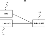
- FIG. 2 is a diagram showing an overall configuration example of the animation production system 300 according to the embodiment of the present invention.
- the animation production system 300 can include, for example, an HMD 110, a controller 210, and an image generation device 310 that functions as a host computer.
- An infrared camera (not shown) or the like for detecting the position, orientation, tilt, etc. of the HMD 110 or the controller 210 can be added to the animation production system 300.
- These devices can be connected to each other by wired or wireless means.
- each device is equipped with a USB port, and communication can be established by connecting with a cable.
- HDMI, wired LAN, infrared rays, Bluetooth (registered trademark), WiFi (registered trademark), etc. are wired.
- communication can be established wirelessly.
- the image generation device 310 may be any device having a calculation processing function, such as a PC, a game machine, or a mobile communication terminal.
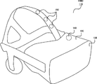
- FIG. 3 shows a schematic view of the appearance of the head-mounted display (hereinafter referred to as HMD) 110 according to the present embodiment.
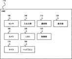
- FIG. 5 shows a functional configuration diagram of the HMD 110 according to the present embodiment.
- the HMD 110 is attached to the user's head and includes a display panel 120 so as to be arranged in front of the user's left and right eyes.
- As the display panel an optical transmissive type and a non-transmissive type display can be considered, but in the present embodiment, a non-transmissive type display panel capable of providing a more immersive feeling is exemplified.
- An image for the left eye and an image for the right eye are displayed on the display panel 120, and an image having a stereoscopic effect can be provided to the user by utilizing the parallax of both eyes. If the image for the left eye and the image for the right eye can be displayed, the display for the left eye and the display for the right eye can be provided separately, or an integrated display for the left eye and the right eye can be provided. is there.
- the housing 130 of the HMD 110 includes a sensor 140.
- the sensor 140 may include, for example, a magnetic sensor, an acceleration sensor, or a gyro sensor, or a combination thereof, in order to detect movements such as the orientation and tilt of the user's head.
- the vertical direction of the user's head is the Y-axis, and of the axes orthogonal to the Y-axis, the axis that connects the center of the display panel 120 and the user and corresponds to the front-back direction of the user is the Z-axis, and the Y-axis and the Z-axis.
- the senor 140 When the axis corresponding to the user's left-right direction is the X-axis, the sensor 140 has a rotation angle around the X-axis (so-called pitch angle), a rotation angle around the Y-axis (so-called yaw angle), and Z. The rotation angle around the axis (so-called roll angle) can be detected.
- the housing 130 of the HMD 110 may include a plurality of light sources 150 (for example, infrared light LED, visible light LED).
- a camera for example, an infrared light camera, a visible light camera
- the HMD 110 may be provided with a camera for detecting a light source installed in the housing 130 of the HMD 110.
- the housing 130 of the HMD 110 may also include an eye tracking sensor.
- Eye tracking sensors are used to detect the gaze direction and gaze point of the user's left and right eyes.
- Various types of eye tracking sensors can be considered. For example, the position of the reflected light on the cornea formed by irradiating the left eye and the right eye with weak infrared light is used as a reference point, and the position of the pupil with respect to the position of the reflected light is used as a reference point.
- a method of detecting the line-of-sight direction and detecting the intersection of the line-of-sight directions of the left eye and the right eye as the gazing point can be considered.
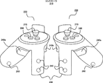
- FIG. 4 shows a schematic view of the appearance of the controller 210 according to the present embodiment.
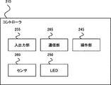
- FIG. 6 shows a functional configuration diagram of the controller 210 according to the present embodiment.
- the controller 210 can support the user to make a predetermined input in the virtual space.
- the controller 210 can be configured as a set of controllers for the left hand 220 and the right hand 230.
- the left-hand controller 220 and the right-hand controller 230 can each have an operation trigger button 240, an infrared LED 250, a sensor 260, a joystick 270, and a menu button 280.
- the operation trigger button 240 is arranged as 240a and 240b at positions assuming that when the grip 235 of the controller 210 is gripped, an operation such as pulling the trigger with the middle finger and the index finger is performed.
- a plurality of infrared LEDs 250 are provided on the frame 245 formed in a ring shape downward from both side surfaces of the controller 210, and the positions of these infrared LEDs are detected by a camera (not shown) provided outside the controller. The position, orientation and tilt of the controller 210 in a specific space can be detected.
- the controller 210 can incorporate a sensor 260 in order to detect an operation such as the orientation or tilt of the controller 210.
- the sensor 260 may include, for example, a magnetic sensor, an acceleration sensor, a gyro sensor, or a combination thereof.
- a joystick 270 and a menu button 280 can be provided on the upper surface of the controller 210. The joystick 270 can be moved in the 360-degree direction about the reference point, and it is assumed that the joystick 270 is operated by the thumb when the grip 235 of the controller 210 is gripped. It is assumed that the menu button 280 is also operated with the thumb.
- the controller 210 may also include a vibrator (not shown) for giving vibration to the hand of the user who operates the controller 210.
- the controller 210 inputs and outputs in order to output information such as the user's input contents via a button or a joystick and the position, orientation and tilt of the controller 210 via a sensor or the like, and to receive information from the host computer. It has a unit and a communication unit.
- the system determines the movement and posture of the user's hand based on whether or not the user holds the controller 210 and operates various buttons and joysticks, and the information detected by the infrared LED and the sensor, and pseudo in the virtual space.
- the user's hand can be displayed and operated.
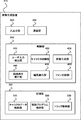
- FIG. 7 shows a functional configuration diagram of the image generation device 310 according to the present embodiment.
- the image generator 310 stores user input information transmitted from the HMD 110 or the controller 210, information on the user's head movement or controller movement or operation acquired by a sensor or the like, and performs a predetermined calculation process.
- Devices such as PCs, game consoles, mobile communication terminals, etc., which have a function for generating images, can be used.
- the image generation device 310 can include, for example, an input / output unit 320 for establishing a wired connection with peripheral devices such as the HMD 110 and the controller 210, and includes infrared rays, Bluetooth (registered trademark), WiFi (registered trademark), and the like.
- a communication unit 330 for establishing a wireless connection can be provided.
- Information regarding the operation of the user's head and the operation or operation of the controller received from the HMD 110 and / or the controller 210 via the input / output unit 320 and / or the communication unit 330 is transmitted in the control unit 340 to the position of the user. It is detected as input content including movements such as line of sight and posture, utterance, operation, etc., and the character is controlled by executing the control program stored in the storage unit 350 according to the input content of the user, and the image is displayed. Is performed.
- the control unit 340 can be configured by a CPU, but by further providing a GPU specialized for image processing, information processing and image processing can be dispersed and overall processing efficiency can be improved.
- the image generation device 310 can also communicate with another calculation processing device and have the other calculation processing device share information processing and image processing.
- the control unit 340 includes a user input detection unit 410 that detects information about the user's head movement, user's speech, and controller operation and operation received from the HMD 110 and / or the controller 210, and a storage unit 350 in advance. It has a character control unit 420 that executes a control program stored in the control program storage unit for a character stored in the character data storage unit 440, and an image generation unit 430 that generates an image based on the character control.
- information such as the orientation and tilt of the user's head and the movement of the hand detected via the HMD 110 and the controller 210 is created according to the movement and restrictions of the joints of the human body.
- control unit 340 has a recording / reproducing execution unit 440 that records and reproduces the image-generated character on the track, and an editing execution unit 450 that edits each track and generates the final content. Further, the control unit 340 has a fan control unit 460 for controlling the arrangement position, the air volume, and the wind direction of the fan 6 in the virtual space 1.
- the storage unit 350 has a character data storage unit 510 that stores information related to the character such as character attributes in addition to the character image data. Further, the control program storage unit 520 stores a program for controlling the movement and facial expression of the character in the virtual space. Further, the storage unit 350 has a track storage unit 530 that stores action data composed of parameters that control the movement of the character (including the movement of the paper) in the moving image generated by the image generation unit 630.
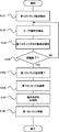
- FIG. 8 is a flowchart illustrating an example of track generation and editing processing according to the embodiment of the present invention.
- the recording / playback execution unit 440 of the control unit 340 of the image generation device 310 stores the action data of the moving image related to the operation by the first character in the virtual space in the first track of the track storage unit 530.
- the position of the camera that shoots the character and the viewpoint of the camera (for example, FPV, TPV, etc.) can be set.
- the position where the cameraman 2 is arranged and the angle of the camera 3 can be set with respect to the character 4 corresponding to the first character.
- the recording start operation may be instructed by a remote controller such as the controller 210, or may be instructed by another terminal.
- this operation may be performed by a user who plays the character who wears the HMD 110 and operates the controller 210, or may be performed by a user other than the user who plays the character. Further, the recording process may be automatically started based on the detection of the operation by the user who plays the character described later.
- the user input detection unit 410 of the control unit 340 detects information regarding the operation of the user's head, the user's utterance, and the operation and operation of the controller received from the HMD 110 and / or the controller 210 (S102). ). For example, when the user wearing the HMD 110 tilts his / her head, the sensor 140 provided in the HMD 110 detects the tilt and transmits information about the tilt to the image generation device 310. The image generation device 310 receives information about the user's movement via the communication unit 330, and the user input detection unit 410 detects the movement of the user's head based on the received information.
- the sensor 260 provided in the controller performs the operation and / or operation. It detects and transmits information about the operation and / or operation to the image generator 310.
- the image generation device 310 receives information on the user's controller operation and operation via the communication unit 330, and the user input detection unit 410 detects the user's controller operation and operation based on the received information.
- the character control unit 420 of the control unit 340 controls the operation of the first character in the virtual space based on the detected operation of the user (S103). For example, the character control unit 420 controls to tilt the head of the first character based on the detection of the action of the user tilting the head. Further, based on the detection that the user lifts the controller and presses a predetermined button on the controller, the character control unit 420 controls to grasp something while extending the arm of the first character upward. To do. In this way, the character control unit 420 controls the user input detection unit 410 to perform the corresponding operation each time the user input detection unit 410 detects an operation by the user transmitted from the HMD 110 or the controller 210.
- the operation and / or the parameter related to the operation detected by the user input detection unit 410 is stored in the first track of the track storage unit 530. Further, it is possible to control the character to perform a predetermined performance movement without relying on user input, and it is possible to store action data related to the predetermined performance movement in the first track, or the user. It is also possible to store both the action by the operation and the action data related to the predetermined operation.
- the recording / playback execution unit 440 confirms whether the instruction to end the recording has been received from the user (S104), and when the instruction to end the recording is received, the recording of the first track related to the first character is completed. (S105).
- the recording / playback execution unit 440 continues the recording process unless it receives an instruction to end recording from the user.
- the recording / playback execution unit 440 can also perform a process of automatically completing the recording when the operation by the user who plays the character is no longer detected. It is also possible to execute the recording end process at a predetermined time by activating a timer instead of receiving an instruction from the user.
- the editing execution unit 450 edits the first track stored in the track storage unit 530 (S106).
- the user edits the first track (T1) associated with the first character via the track editing user interface as shown in FIG. 9A.
- the user interface displays an area in which the first track is stored in chronological order.
- a moving image of a character for example, character 4
- the user interface for track editing is not limited to the above display, and for example, a method of displaying the track name and title (for example, "first character") in a list format can be considered.
- the fan control unit 460 controls the air volume and direction of the fan in order to control the movement of the hair of the first character stored in the first track (S107).
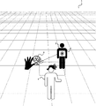
- the user input detection unit 410 of the control unit 310 detects an operation signal by the user pressing an operation button of the controller 420, and the fan control unit 460 detects an operation signal as shown in FIG.
- the fan 6 is arranged at a position facing the character 4, and the air volume and direction of the fan are adjusted.
- the character control unit 420 controls that the wind generated by the fan 6 changes its movement according to the character 4, including the direction of the hair of the character 4.
- the object whose movement is controlled can be a desired part of the character such as the character's clothes, accessories, and an object (letter, etc.) held in the hand.
- the object whose movement is controlled can be a desired part of the character such as the character's clothes, accessories, and an object (letter, etc.) held in the hand.
- the object whose movement is controlled can be a desired part of the character such as the character's clothes, accessories, and an object (letter, etc.) held in the hand.
- a plurality of fans in the virtual space it is possible to adjust the strength and direction of the movement by the wind within the same character, such as weakening the movement of clothes while strengthening the movement of hair.
- the editing execution unit 450 performs a process of updating the first track in response to a user's request or by automatically saving the edited content (S108).
- FIG. 10 (b) in addition to the form of overwriting the motion parameters related to the character's hair movement updated in the first track as action data, as shown in FIG. 9 (c), the original A new track (T2) is generated while leaving the track (T1) of the character, and the action data related to the character's movement is stored in the generated track (T2) together with the updated action data related to the character's hair movement. You can also do it. As a result, the user can more flexibly edit each track.
- the character movement linked to the user movement is stored in the track, and the character stored in the track is compared with the character.
- the character stored in the track is compared with the character.
- the track generation method and the editing method have been described by taking a character as an example, but the present embodiment includes not only characters but also objects (vehicles, structures, articles, etc.) including characters.
- the disclosed method can also be applied.
- the image generation device 310 is described as being separate from the HMD 110, but the HMD 110 may be provided with all or a part of the configurations and functions provided by the image generation device 310.
Abstract
[Problem] To make it possible to shoot animation in a virtual space. [Solution] Provided is an animation production method for providing a virtual space in which a predetermined object is disposed. The animation production method includes: detecting a motion of a user who wears a head mounted display; controlling a motion of the object on the basis of the detected motion of the user; shooting the motion of the object; storing an image including the shot motion of the object in a predetermined track; and changing a motion of hair of the object stored in the predetermined track.
Description
本発明は、アニメーション制作システムに関する。
The present invention relates to an animation production system.
仮想空間内に仮想カメラを配置することが行われている(特許文献1参照)。
A virtual camera is placed in the virtual space (see Patent Document 1).
仮想空間内でアニメーションを撮影しようとする取り組みが行われてこなかった。
No efforts have been made to shoot animation in the virtual space.
本発明はこのような背景を鑑みてなされたものであり、仮想空間内でアニメーションを撮影することのできる技術を提供することを目的とする。
The present invention has been made in view of such a background, and an object of the present invention is to provide a technique capable of shooting an animation in a virtual space.
上記課題を解決するための本発明の主たる発明は、所定のオブジェクトが配置される仮想空間を提供する、アニメーション制作方法であって、ヘッドマウントディスプレイを装着するユーザの動作を検出し、前記検出したユーザの動作に基づいて、オブジェクトの動作を制御し、前記オブジェクトの動作を撮影し、前記撮影されたオブジェクトの動作を含む画像を所定のトラックに格納し、前記所定のトラックに格納されたオブジェクトの表情を変更すること、を含む。
The main invention of the present invention for solving the above problems is an animation production method that provides a virtual space in which a predetermined object is arranged, and detects the movement of a user wearing a head-mounted display, and detects the movement of the user. Based on the user's motion, the motion of the object is controlled, the motion of the object is photographed, an image including the motion of the photographed object is stored in a predetermined track, and the motion of the object stored in the predetermined track is stored. Includes changing facial expressions.
その他本願が開示する課題やその解決方法については、発明の実施形態の欄及び図面により明らかにされる。
Other problems disclosed in the present application and solutions thereof will be clarified in the columns and drawings of the embodiments of the invention.
本発明によれば、仮想空間内でアニメーションを撮影することができる。
According to the present invention, it is possible to shoot an animation in a virtual space.
本発明の実施形態の内容を列記して説明する。本発明の実施の形態によるアニメーション制作方法は、以下のような構成を備える。
The contents of the embodiments of the present invention will be listed and described. The animation production method according to the embodiment of the present invention has the following configurations.
[項目1]
所定のオブジェクトが配置される仮想空間を提供する、アニメーション制作方法であって、
ヘッドマウントディスプレイを装着するユーザの動作を検出し、
前記検出したユーザの動作に基づいて、オブジェクトの動作を制御し、
前記オブジェクトの動作を撮影し、
前記撮影されたオブジェクトの動作に関するアクションデータを所定のトラックに格納し、
前記所定のトラックに格納されたオブジェクトの髪の動作を変更すること、を含む方法。
[項目2]
前記変更されたオブジェクトの髪の動作に関するアクションデータを前記トラックに保存することを含む、項目1に記載の方法。 [Item 1]
An animation production method that provides a virtual space in which a given object is placed.
Detects the movement of the user wearing the head-mounted display and detects
Control the behavior of the object based on the detected user behavior
Take a picture of the movement of the object
Action data related to the movement of the photographed object is stored in a predetermined track, and
A method comprising changing the behavior of the hair of an object stored in the predetermined track.
[Item 2]
The method of item 1, wherein action data relating to the behavior of the hair of the modified object is stored in the track.
本発明の一実施形態に係るアニメーション制作システムの具体例を、以下に図面を参照しつつ説明する。なお、本発明はこれらの例示に限定されるものではなく、特許請求の範囲によって示され、特許請求の範囲と均等の意味及び範囲内でのすべての変更が含まれることが意図される。以下の説明では、図面の説明において同一の要素には同一の符号を付し、重複する説明を省略する。
A specific example of the animation production system according to the embodiment of the present invention will be described below with reference to the drawings. It should be noted that the present invention is not limited to these examples, and is indicated by the scope of claims, and is intended to include all modifications within the meaning and scope equivalent to the scope of claims. In the following description, the same elements are designated by the same reference numerals in the description of the drawings, and duplicate description will be omitted.
<概要>
図1は、本実施形態のアニメーション制作システムにおいてユーザが装着するヘッドマウントディスプレイ(HMD)に表示される仮想空間の一例を示す図である。本実施形態のアニメーション制作システムでは、仮想空間1にキャラクタ4とカメラ3とを配置し、カメラ3を用いてキャラクタ4を撮影する。また、仮想空間1にはカメラマン2が配置され、カメラマン2によりカメラ3が仮想的に操作される。本実施形態のアニメーション制作システムでは、ユーザは、図1に示すように仮想空間1をTPV(Third Person View;三人称視点)で俯瞰しながらキャラクタ4やカメラ3を配置したり、カメラマン2としてFPV(First Person View;一人称支援)でキャラクタ4を撮影したり、FPVでキャラクタ4の演技を行ったりしながら、アニメーションを制作していく。また、仮想空間1内には複数のキャラクタ(図1の例では、キャラクタ4およびキャラクタ5)を配置することができ、ユーザは、キャラクタ4とキャラクタ5とにそれぞれ憑依しながら演技を行うことができる。すなわち、本実施形態のアニメーション制作システムでは、一人が何役もの役割(ロール)を果たすことができる。また、カメラマン2としてカメラ2を仮想的に操作しながら撮影を行うことができるので、自然なカメラワークを実現することが可能となり、撮影される動画の表現を豊かにすることができる。また、仮想空間内のファン6から、キャラクタ4とキャラクタ5に対して風を当てることで、これらのキャラクタの髪や衣服を靡かせる、といった演出を作り出すこともできる。ファン6は現実世界のファンと同じく、風量は風向きの調整といった機能を有することができる。 <Overview>
FIG. 1 is a diagram showing an example of a virtual space displayed on a head-mounted display (HMD) worn by a user in the animation production system of the present embodiment. In the animation production system of the present embodiment, the character 4 and thecamera 3 are arranged in the virtual space 1, and the character 4 is photographed by using the camera 3. Further, a cameraman 2 is arranged in the virtual space 1, and the cameraman 2 virtually operates the camera 3. In the animation production system of the present embodiment, as shown in FIG. 1, the user can arrange the character 4 and the camera 3 while looking down at the virtual space 1 from a TPV (Third Person View), or can use the FPV (3rd person view) as the cameraman 2. While shooting character 4 with First Person View (first person support) and acting character 4 with FPV, we will create animation. Further, a plurality of characters (characters 4 and 5 in the example of FIG. 1) can be arranged in the virtual space 1, and the user can perform acting while possessing the characters 4 and 5, respectively. it can. That is, in the animation production system of the present embodiment, one person can play many roles. Further, since the cameraman 2 can perform shooting while virtually operating the camera 2, it is possible to realize natural camera work and enrich the expression of the moving image to be shot. In addition, by blowing wind on the characters 4 and 5 from the fan 6 in the virtual space, it is possible to create an effect such as making the hair and clothes of these characters lie. Like a fan in the real world, the fan 6 can have a function of adjusting the air volume and the wind direction.
図1は、本実施形態のアニメーション制作システムにおいてユーザが装着するヘッドマウントディスプレイ(HMD)に表示される仮想空間の一例を示す図である。本実施形態のアニメーション制作システムでは、仮想空間1にキャラクタ4とカメラ3とを配置し、カメラ3を用いてキャラクタ4を撮影する。また、仮想空間1にはカメラマン2が配置され、カメラマン2によりカメラ3が仮想的に操作される。本実施形態のアニメーション制作システムでは、ユーザは、図1に示すように仮想空間1をTPV(Third Person View;三人称視点)で俯瞰しながらキャラクタ4やカメラ3を配置したり、カメラマン2としてFPV(First Person View;一人称支援)でキャラクタ4を撮影したり、FPVでキャラクタ4の演技を行ったりしながら、アニメーションを制作していく。また、仮想空間1内には複数のキャラクタ(図1の例では、キャラクタ4およびキャラクタ5)を配置することができ、ユーザは、キャラクタ4とキャラクタ5とにそれぞれ憑依しながら演技を行うことができる。すなわち、本実施形態のアニメーション制作システムでは、一人が何役もの役割(ロール)を果たすことができる。また、カメラマン2としてカメラ2を仮想的に操作しながら撮影を行うことができるので、自然なカメラワークを実現することが可能となり、撮影される動画の表現を豊かにすることができる。また、仮想空間内のファン6から、キャラクタ4とキャラクタ5に対して風を当てることで、これらのキャラクタの髪や衣服を靡かせる、といった演出を作り出すこともできる。ファン6は現実世界のファンと同じく、風量は風向きの調整といった機能を有することができる。 <Overview>
FIG. 1 is a diagram showing an example of a virtual space displayed on a head-mounted display (HMD) worn by a user in the animation production system of the present embodiment. In the animation production system of the present embodiment, the character 4 and the
<全体構成>
図2は、本発明の一実施形態に係るアニメーション制作システム300の全体構成例を示す図である。アニメーション制作システム300は、例えば、HMD110、コントローラ210及びホストコンピュータとして機能する画像生成装置310を含んで構成することができる。アニメーション制作システム300には、HMD110やコントローラ210の位置、向き及び傾き等を検出するための赤外線カメラ(図示せず)等を追加することもできる。これらの装置は、相互に、有線又は無線手段により接続することができる。例えば、各々の装置にUSBポートを備え、ケーブルで接続することで通信を確立することもできるし、他に、HDMI、有線LAN、赤外線、Bluetooth(登録商標)、WiFi(登録商標)等の有線又は無線により通信を確立することもできる。画像生成装置310は、PC、ゲーム機、携帯通信端末等、計算処理機能を有する装置であればよい。 <Overall configuration>
FIG. 2 is a diagram showing an overall configuration example of theanimation production system 300 according to the embodiment of the present invention. The animation production system 300 can include, for example, an HMD 110, a controller 210, and an image generation device 310 that functions as a host computer. An infrared camera (not shown) or the like for detecting the position, orientation, tilt, etc. of the HMD 110 or the controller 210 can be added to the animation production system 300. These devices can be connected to each other by wired or wireless means. For example, each device is equipped with a USB port, and communication can be established by connecting with a cable. In addition, HDMI, wired LAN, infrared rays, Bluetooth (registered trademark), WiFi (registered trademark), etc. are wired. Alternatively, communication can be established wirelessly. The image generation device 310 may be any device having a calculation processing function, such as a PC, a game machine, or a mobile communication terminal.
図2は、本発明の一実施形態に係るアニメーション制作システム300の全体構成例を示す図である。アニメーション制作システム300は、例えば、HMD110、コントローラ210及びホストコンピュータとして機能する画像生成装置310を含んで構成することができる。アニメーション制作システム300には、HMD110やコントローラ210の位置、向き及び傾き等を検出するための赤外線カメラ(図示せず)等を追加することもできる。これらの装置は、相互に、有線又は無線手段により接続することができる。例えば、各々の装置にUSBポートを備え、ケーブルで接続することで通信を確立することもできるし、他に、HDMI、有線LAN、赤外線、Bluetooth(登録商標)、WiFi(登録商標)等の有線又は無線により通信を確立することもできる。画像生成装置310は、PC、ゲーム機、携帯通信端末等、計算処理機能を有する装置であればよい。 <Overall configuration>
FIG. 2 is a diagram showing an overall configuration example of the
<HMD110>
図3は、本実施形態に係るヘッドマウントディスプレイ(以下:HMD)110の外観の模式図を示す。図5は、本実施形態に係るHMD110の機能構成図を示す。HMD110はユーザの頭部に装着され、ユーザの左右の眼前に配置されるよう表示パネル120を備える。表示パネルとしては、光学透過型と非透過型のディスプレイが考えられるが、本実施形態では、より没入感を提供可能な非透過型の表示パネルを例示する。表示パネル120には、左目用画像と右目用画像とが表示され、両目の視差を利用することにより立体感のある画像をユーザに提供することができる。左目用画像と右目用画像とを表示することができれば、左目用ディスプレイと右目用ディスプレイとを個別に備えることも可能であるし、左目用及び右目用の一体型のディスプレイを備えることも可能である。 <HMD110>
FIG. 3 shows a schematic view of the appearance of the head-mounted display (hereinafter referred to as HMD) 110 according to the present embodiment. FIG. 5 shows a functional configuration diagram of the HMD 110 according to the present embodiment. The HMD 110 is attached to the user's head and includes adisplay panel 120 so as to be arranged in front of the user's left and right eyes. As the display panel, an optical transmissive type and a non-transmissive type display can be considered, but in the present embodiment, a non-transmissive type display panel capable of providing a more immersive feeling is exemplified. An image for the left eye and an image for the right eye are displayed on the display panel 120, and an image having a stereoscopic effect can be provided to the user by utilizing the parallax of both eyes. If the image for the left eye and the image for the right eye can be displayed, the display for the left eye and the display for the right eye can be provided separately, or an integrated display for the left eye and the right eye can be provided. is there.
図3は、本実施形態に係るヘッドマウントディスプレイ(以下:HMD)110の外観の模式図を示す。図5は、本実施形態に係るHMD110の機能構成図を示す。HMD110はユーザの頭部に装着され、ユーザの左右の眼前に配置されるよう表示パネル120を備える。表示パネルとしては、光学透過型と非透過型のディスプレイが考えられるが、本実施形態では、より没入感を提供可能な非透過型の表示パネルを例示する。表示パネル120には、左目用画像と右目用画像とが表示され、両目の視差を利用することにより立体感のある画像をユーザに提供することができる。左目用画像と右目用画像とを表示することができれば、左目用ディスプレイと右目用ディスプレイとを個別に備えることも可能であるし、左目用及び右目用の一体型のディスプレイを備えることも可能である。 <HMD110>
FIG. 3 shows a schematic view of the appearance of the head-mounted display (hereinafter referred to as HMD) 110 according to the present embodiment. FIG. 5 shows a functional configuration diagram of the HMD 110 according to the present embodiment. The HMD 110 is attached to the user's head and includes a
HMD110の筐体部130は、センサ140を備える。センサ140は、ユーザの頭部の向きや傾きといった動作を検出するために、図示しないが、例えば、磁気センサ、加速度センサ、もしくはジャイロセンサのいずれか、またはこれらの組み合わせを備えることができる。ユーザの頭部の垂直方向をY軸とし、Y軸と直交する軸のうち、表示パネル120の中心とユーザとを結ぶ、ユーザの前後方向に相当する軸をZ軸とし、Y軸及びZ軸と直交し、ユーザの左右方向に相当する軸をX軸とするとき、センサ140は、X軸まわりの回転角(いわゆる、ピッチ角)、Y軸まわりの回転角(いわゆる、ヨー角)、Z軸まわりの回転角(いわゆる、ロール角)を検出することができる。
The housing 130 of the HMD 110 includes a sensor 140. Although not shown, the sensor 140 may include, for example, a magnetic sensor, an acceleration sensor, or a gyro sensor, or a combination thereof, in order to detect movements such as the orientation and tilt of the user's head. The vertical direction of the user's head is the Y-axis, and of the axes orthogonal to the Y-axis, the axis that connects the center of the display panel 120 and the user and corresponds to the front-back direction of the user is the Z-axis, and the Y-axis and the Z-axis. When the axis corresponding to the user's left-right direction is the X-axis, the sensor 140 has a rotation angle around the X-axis (so-called pitch angle), a rotation angle around the Y-axis (so-called yaw angle), and Z. The rotation angle around the axis (so-called roll angle) can be detected.
センサ140に代えて、またはセンサ140に加えて、HMD110の筐体部130は、複数の光源150(例えば、赤外光LED、可視光LED)を備えることもできる。HMD110の外部(例えば、室内等)に設置されたカメラ(例えば、赤外光カメラ、可視光カメラ)がこれらの光源を検出することで、特定の空間におけるHMD110の位置、向き、傾きを検出することができる。または、同じ目的で、HMD110に、HMD110の筐体部130に設置された光源を検出するためのカメラを備えることもできる。
Instead of the sensor 140, or in addition to the sensor 140, the housing 130 of the HMD 110 may include a plurality of light sources 150 (for example, infrared light LED, visible light LED). A camera (for example, an infrared light camera, a visible light camera) installed outside the HMD 110 (for example, indoors) detects these light sources to detect the position, orientation, and inclination of the HMD 110 in a specific space. be able to. Alternatively, for the same purpose, the HMD 110 may be provided with a camera for detecting a light source installed in the housing 130 of the HMD 110.
HMD110の筐体部130は、アイトラッキング・センサを備えることもできる。アイトラッキング・センサは、ユーザの左目及び右目の視線方向及び注視点を検出するために用いられる。アイトラッキング・センサとしては様々な方式が考えられるが、例えば、左目および右目に弱い赤外光を照射してできる角膜上の反射光の位置を基準点とし、反射光の位置に対する瞳孔の位置により視線方向を検出し、左目及び右目の視線方向の交点を注視点として検出する方法などが考えられる。
The housing 130 of the HMD 110 may also include an eye tracking sensor. Eye tracking sensors are used to detect the gaze direction and gaze point of the user's left and right eyes. Various types of eye tracking sensors can be considered. For example, the position of the reflected light on the cornea formed by irradiating the left eye and the right eye with weak infrared light is used as a reference point, and the position of the pupil with respect to the position of the reflected light is used as a reference point. A method of detecting the line-of-sight direction and detecting the intersection of the line-of-sight directions of the left eye and the right eye as the gazing point can be considered.
<コントローラ210>
図4は、本実施形態に係るコントローラ210の外観の模式図を示す。図6は、本実施形態に係るコントローラ210の機能構成図を示す。コントローラ210により、仮想空間内において、ユーザが所定の入力を行うことをサポートすることができる。コントローラ210は、左手用220及び右手用230のコントローラのセットとして構成することができる。左手用コントローラ220及び右手用コントローラ230は、各々操作用トリガーボタン240、赤外線LED250、センサ260、ジョイスティック270、メニューボタン280を有することができる。 <Controller 210>
FIG. 4 shows a schematic view of the appearance of thecontroller 210 according to the present embodiment. FIG. 6 shows a functional configuration diagram of the controller 210 according to the present embodiment. The controller 210 can support the user to make a predetermined input in the virtual space. The controller 210 can be configured as a set of controllers for the left hand 220 and the right hand 230. The left-hand controller 220 and the right-hand controller 230 can each have an operation trigger button 240, an infrared LED 250, a sensor 260, a joystick 270, and a menu button 280.
図4は、本実施形態に係るコントローラ210の外観の模式図を示す。図6は、本実施形態に係るコントローラ210の機能構成図を示す。コントローラ210により、仮想空間内において、ユーザが所定の入力を行うことをサポートすることができる。コントローラ210は、左手用220及び右手用230のコントローラのセットとして構成することができる。左手用コントローラ220及び右手用コントローラ230は、各々操作用トリガーボタン240、赤外線LED250、センサ260、ジョイスティック270、メニューボタン280を有することができる。 <
FIG. 4 shows a schematic view of the appearance of the
操作用トリガーボタン240は、コントローラ210のグリップ235を把持したときに、中指及び人差し指でトリガーを引くような操作を行うことを想定した位置に240a、240bとして配置される。コントローラ210の両側面から下方にリング状に形成されるフレーム245には、複数の赤外線LED250が備えられ、コントローラ外部に備えられるカメラ(図示せず)により、これらの赤外線LEDの位置を検出することで、特定の空間におけるコントローラ210の位置、向き及び傾きを検出することができる。
The operation trigger button 240 is arranged as 240a and 240b at positions assuming that when the grip 235 of the controller 210 is gripped, an operation such as pulling the trigger with the middle finger and the index finger is performed. A plurality of infrared LEDs 250 are provided on the frame 245 formed in a ring shape downward from both side surfaces of the controller 210, and the positions of these infrared LEDs are detected by a camera (not shown) provided outside the controller. The position, orientation and tilt of the controller 210 in a specific space can be detected.
また、コントローラ210は、コントローラ210の向きや傾きといった動作を検出するために、センサ260を内蔵することができる。センサ260として、図示しないが、例えば、磁気センサ、加速度センサ、もしくはジャイロセンサのいずれか、またはこれらの組み合わせを備えることができる。さらに、コントローラ210の上面には、ジョイスティック270及びメニューボタン280を備えることができる。ジョイスティック270は、基準点を中心に360度方向に動かすことができ、コントローラ210のグリップ235を把持したときに、親指で操作されることが想定される。メニューボタン280もまた同様に、親指で操作されることが想定される。さらに、コントローラ210は、コントローラ210を操作するユーザの手に振動を与えるためのバイブレータ(図示せず)を内蔵することもできる。ボタンやジョイスティックを介したユーザの入力内容やセンサ等を介したコントローラ210の位置、向き及び傾きといった情報を出力するため、また、ホストコンピュータからの情報を受信するために、コントローラ210は、入出力部及び通信部を有する。
Further, the controller 210 can incorporate a sensor 260 in order to detect an operation such as the orientation or tilt of the controller 210. Although not shown, the sensor 260 may include, for example, a magnetic sensor, an acceleration sensor, a gyro sensor, or a combination thereof. Further, a joystick 270 and a menu button 280 can be provided on the upper surface of the controller 210. The joystick 270 can be moved in the 360-degree direction about the reference point, and it is assumed that the joystick 270 is operated by the thumb when the grip 235 of the controller 210 is gripped. It is assumed that the menu button 280 is also operated with the thumb. Further, the controller 210 may also include a vibrator (not shown) for giving vibration to the hand of the user who operates the controller 210. The controller 210 inputs and outputs in order to output information such as the user's input contents via a button or a joystick and the position, orientation and tilt of the controller 210 via a sensor or the like, and to receive information from the host computer. It has a unit and a communication unit.
ユーザがコントローラ210を把持し、各種ボタンやジョイスティックを操作することの有無、及び赤外線LEDやセンサにより検出される情報によって、システムはユーザの手の動作や姿勢を決定し、仮想空間内において擬似的にユーザの手を表示させ、動作させることができる。
The system determines the movement and posture of the user's hand based on whether or not the user holds the controller 210 and operates various buttons and joysticks, and the information detected by the infrared LED and the sensor, and pseudo in the virtual space. The user's hand can be displayed and operated.
<画像生成装置310>
図7は、本実施形態に係る画像生成装置310の機能構成図を示す。画像生成装置310としては、HMD110やコントローラ210から送信された、ユーザ入力情報やセンサ等により取得されたユーザの頭部動作やコントローラの動作や操作に関する情報を記憶し、所定の計算処理を行い、画像を生成するための機能を有する、PC、ゲーム機及び携帯通信端末等といった装置を使用することができる。画像生成装置310は、例えば、HMD110やコントローラ210等の周辺装置との有線による接続を確立するための入出力部320を備えることができ、赤外線、Bluetooth(登録商標)やWiFi(登録商標)等無線による接続を確立するための通信部330を備えることができる。入出力部320及び/又は通信部330を介して、HMD110及び/又はコントローラ210から受信された、ユーザの頭部の動作やコントローラの動作や操作に関する情報は、制御部340において、ユーザの位置、視線、姿勢等の動作、発話、操作等を含めた入力内容として検出され、ユーザの入力内容に応じて、記憶部350に格納された制御プログラムを実行することで、キャラクタの制御を行い、画像を生成するといった処理がなされる。制御部340は、CPUで構成することもできるが、画像処理に特化したGPUをさらに設けることで、情報処理と画像処理を分散化し、全体の処理の効率化を図ることもできる。画像生成装置310はまた、他の計算処理装置と通信を行い、他の計算処理装置に情報処理や画像処理を分担させることもできる。 <Image generator 310>
FIG. 7 shows a functional configuration diagram of theimage generation device 310 according to the present embodiment. The image generator 310 stores user input information transmitted from the HMD 110 or the controller 210, information on the user's head movement or controller movement or operation acquired by a sensor or the like, and performs a predetermined calculation process. Devices such as PCs, game consoles, mobile communication terminals, etc., which have a function for generating images, can be used. The image generation device 310 can include, for example, an input / output unit 320 for establishing a wired connection with peripheral devices such as the HMD 110 and the controller 210, and includes infrared rays, Bluetooth (registered trademark), WiFi (registered trademark), and the like. A communication unit 330 for establishing a wireless connection can be provided. Information regarding the operation of the user's head and the operation or operation of the controller received from the HMD 110 and / or the controller 210 via the input / output unit 320 and / or the communication unit 330 is transmitted in the control unit 340 to the position of the user. It is detected as input content including movements such as line of sight and posture, utterance, operation, etc., and the character is controlled by executing the control program stored in the storage unit 350 according to the input content of the user, and the image is displayed. Is performed. The control unit 340 can be configured by a CPU, but by further providing a GPU specialized for image processing, information processing and image processing can be dispersed and overall processing efficiency can be improved. The image generation device 310 can also communicate with another calculation processing device and have the other calculation processing device share information processing and image processing.
図7は、本実施形態に係る画像生成装置310の機能構成図を示す。画像生成装置310としては、HMD110やコントローラ210から送信された、ユーザ入力情報やセンサ等により取得されたユーザの頭部動作やコントローラの動作や操作に関する情報を記憶し、所定の計算処理を行い、画像を生成するための機能を有する、PC、ゲーム機及び携帯通信端末等といった装置を使用することができる。画像生成装置310は、例えば、HMD110やコントローラ210等の周辺装置との有線による接続を確立するための入出力部320を備えることができ、赤外線、Bluetooth(登録商標)やWiFi(登録商標)等無線による接続を確立するための通信部330を備えることができる。入出力部320及び/又は通信部330を介して、HMD110及び/又はコントローラ210から受信された、ユーザの頭部の動作やコントローラの動作や操作に関する情報は、制御部340において、ユーザの位置、視線、姿勢等の動作、発話、操作等を含めた入力内容として検出され、ユーザの入力内容に応じて、記憶部350に格納された制御プログラムを実行することで、キャラクタの制御を行い、画像を生成するといった処理がなされる。制御部340は、CPUで構成することもできるが、画像処理に特化したGPUをさらに設けることで、情報処理と画像処理を分散化し、全体の処理の効率化を図ることもできる。画像生成装置310はまた、他の計算処理装置と通信を行い、他の計算処理装置に情報処理や画像処理を分担させることもできる。 <
FIG. 7 shows a functional configuration diagram of the
制御部340は、HMD110及び/又はコントローラ210から受信された、ユーザの頭部の動作やユーザの発話、また、コントローラの動作や操作に関する情報を検出するユーザ入力検出部410と、予め記憶部350のキャラクタデータ格納部440に格納されたキャラクタに対して、制御プログラム格納部に格納された制御プログラムを実行するキャラクタ制御部420と、キャラクタ制御に基づいて画像を生成する画像生成部430を有する。ここでキャラクタの動作の制御については、HMD110やコントローラ210を介して検出されたユーザ頭部の向きや傾き、手の動作といった情報を、人間の身体の関節の動作や制約に則って作成されたボーン構造の各部の動作に変換し、予め格納されたキャラクタデータに対して、ボーン構造を関連付けることで、ボーン構造の動作を適用させることで実現される。さらに、制御部340は、画像生成されたキャラクタをトラックに録画し、再生する録画再生実行部440と、各トラックを編集し、最終コンテンツを生成する編集実行部450とを有する。また、制御部340は、仮想空間1内のファン6の配置位置、風量及び風向きを制御するためのファン制御部460を有する。
The control unit 340 includes a user input detection unit 410 that detects information about the user's head movement, user's speech, and controller operation and operation received from the HMD 110 and / or the controller 210, and a storage unit 350 in advance. It has a character control unit 420 that executes a control program stored in the control program storage unit for a character stored in the character data storage unit 440, and an image generation unit 430 that generates an image based on the character control. Here, regarding the control of the character's movement, information such as the orientation and tilt of the user's head and the movement of the hand detected via the HMD 110 and the controller 210 is created according to the movement and restrictions of the joints of the human body. It is realized by applying the operation of the bone structure by converting it into the operation of each part of the bone structure and associating the bone structure with the character data stored in advance. Further, the control unit 340 has a recording / reproducing execution unit 440 that records and reproduces the image-generated character on the track, and an editing execution unit 450 that edits each track and generates the final content. Further, the control unit 340 has a fan control unit 460 for controlling the arrangement position, the air volume, and the wind direction of the fan 6 in the virtual space 1.
記憶部350は、キャラクタのイメージデータのほか、キャラクタの属性等キャラクタに関連する情報を格納するキャラクタデータ格納部510を有する。また、制御プログラム格納部520は、仮想空間におけるキャラクタの動作や表情を制御するためのプログラムを格納する。また、記憶部350は、画像生成部630で生成される動画像におけるキャラクタの動き(紙の動きを含む)を制御するパラメータで構成されるアクションデータを格納するトラック格納部530を有する。
The storage unit 350 has a character data storage unit 510 that stores information related to the character such as character attributes in addition to the character image data. Further, the control program storage unit 520 stores a program for controlling the movement and facial expression of the character in the virtual space. Further, the storage unit 350 has a track storage unit 530 that stores action data composed of parameters that control the movement of the character (including the movement of the paper) in the moving image generated by the image generation unit 630.
図8は、本発明の実施形態に係る、トラック生成及び編集処理の一例を説明するフローチャートである。
FIG. 8 is a flowchart illustrating an example of track generation and editing processing according to the embodiment of the present invention.
まず、画像生成装置310の制御部340の録画再生実行部440は、仮想空間における、第1のキャラクタによる動作に関連する動画像のアクションデータを、トラック格納部530の第1のトラックに格納するための録画を開始する(S101)。ここで、キャラクタを撮影するカメラの位置、カメラの視点(例えば、FPV、TPV等)を設定することもできる。例えば、図1に示す仮想空間1において、第1のキャラクタに対応するキャラクタ4に対し、カメラマン2が配置される位置、また、カメラ3のアングルを設定することができる。録画開始操作は、コントローラ210等のリモートコントローラによって指示されてもよく、他の端末によって指示されてもよい。また、本操作は、HMD110を装着し、コントローラ210を操作する、キャラクタを演じるユーザによって行われてもよく、または、キャラクタを演じるユーザ以外のユーザによって行われてもよい。また、後述のキャラクタを演じるユーザによる動作を検出することに基づいて録画処理を自動的に開始してもよい。
First, the recording / playback execution unit 440 of the control unit 340 of the image generation device 310 stores the action data of the moving image related to the operation by the first character in the virtual space in the first track of the track storage unit 530. (S101). Here, the position of the camera that shoots the character and the viewpoint of the camera (for example, FPV, TPV, etc.) can be set. For example, in the virtual space 1 shown in FIG. 1, the position where the cameraman 2 is arranged and the angle of the camera 3 can be set with respect to the character 4 corresponding to the first character. The recording start operation may be instructed by a remote controller such as the controller 210, or may be instructed by another terminal. Further, this operation may be performed by a user who plays the character who wears the HMD 110 and operates the controller 210, or may be performed by a user other than the user who plays the character. Further, the recording process may be automatically started based on the detection of the operation by the user who plays the character described later.
続いて、制御部340のユーザ入力検出部410は、HMD110及び/又はコントローラ210から受信された、ユーザの頭部の動作やユーザの発話、また、コントローラの動作や操作に関する情報を検出する(S102)。例えば、HMD110を装着するユーザが、頭部を傾けるとHMD110に備えられるセンサ140が、その傾きを検出し、傾きに関する情報を画像生成装置310に送信する。画像生成装置310は、通信部330を介して、ユーザの動作に関する情報を受信し、ユーザ入力検出部410は、受信した情報を基にユーザの頭部の動作を検出する。また、ユーザが、コントローラ210を使って、コントローラ210を持ち上げたり、ボタンを押下したりする等の所定の動作や操作を行ったとき、コントローラに備えられたセンサ260がその動作及び/または操作を検出し、動作及び/または操作に関する情報を画像生成装置310に送信する。画像生成装置310は、通信部330を介して、ユーザのコントローラ動作や操作に関する情報を受信し、ユーザ入力検出部410は、受信した情報を基にユーザのコントローラ動作や操作を検出する。
Subsequently, the user input detection unit 410 of the control unit 340 detects information regarding the operation of the user's head, the user's utterance, and the operation and operation of the controller received from the HMD 110 and / or the controller 210 (S102). ). For example, when the user wearing the HMD 110 tilts his / her head, the sensor 140 provided in the HMD 110 detects the tilt and transmits information about the tilt to the image generation device 310. The image generation device 310 receives information about the user's movement via the communication unit 330, and the user input detection unit 410 detects the movement of the user's head based on the received information. Further, when the user performs a predetermined operation or operation such as lifting the controller 210 or pressing a button using the controller 210, the sensor 260 provided in the controller performs the operation and / or operation. It detects and transmits information about the operation and / or operation to the image generator 310. The image generation device 310 receives information on the user's controller operation and operation via the communication unit 330, and the user input detection unit 410 detects the user's controller operation and operation based on the received information.
続いて、制御部340のキャラクタ制御部420は、検出したユーザの動作に基づいて仮想空間内における第1のキャラクタの動作を制御する(S103)。例えば、ユーザが頭部を傾ける動作を検出したことに基づいて、キャラクタ制御部420は、第1のキャラクタの頭部を傾けるよう制御する。また、ユーザがコントローラを持ち上げ、コントローラの所定のボタンを押下したことを検出したことに基づいて、キャラクタ制御部420は、第1のキャラクタの腕を上方向に伸ばしながら、何かを掴むよう制御する。このように、キャラクタ制御部420は、ユーザ入力検出部410が、HMD110またはコントローラ210から送信されたユーザによる動作を検出する度に、第1のキャラクタが対応する動作を行うよう制御する。ユーザ入力検出部410によって検出された操作及び/または操作に関するパラメータを、トラック格納部530の第1のトラックに格納する格納する。また、ユーザ入力によらずに、キャラクタが所定の演技の動きを実行するよう制御することもでき、この所定の演技の動きに関するアクションデータを第1のトラックに格納することもでき、または、ユーザによる動作と所定の動作に関するアクションデータを両方格納することもできる。
Subsequently, the character control unit 420 of the control unit 340 controls the operation of the first character in the virtual space based on the detected operation of the user (S103). For example, the character control unit 420 controls to tilt the head of the first character based on the detection of the action of the user tilting the head. Further, based on the detection that the user lifts the controller and presses a predetermined button on the controller, the character control unit 420 controls to grasp something while extending the arm of the first character upward. To do. In this way, the character control unit 420 controls the user input detection unit 410 to perform the corresponding operation each time the user input detection unit 410 detects an operation by the user transmitted from the HMD 110 or the controller 210. The operation and / or the parameter related to the operation detected by the user input detection unit 410 is stored in the first track of the track storage unit 530. Further, it is possible to control the character to perform a predetermined performance movement without relying on user input, and it is possible to store action data related to the predetermined performance movement in the first track, or the user. It is also possible to store both the action by the operation and the action data related to the predetermined operation.
続いて、録画再生実行部440は、ユーザから録画終了の指示を受け付けたかを確認し(S104)、録画終了の指示を受け付けたときには、第1のキャラクタに関連する第1のトラックの録画を完了する(S105)。録画再生実行部440は、ユーザから録画終了の指示を受け付けない限り、録画処理を継続する。ここで、録画再生実行部440は、キャラクタを演じるユーザによる動作を検出しなくなったときに、自動的に録画を完了する処理を行うこともできる。また、ユーザによる指示を受けつけるのではなく、タイマーを作動させることで所定の時間に録画終了の処理を実行することもできる。
Subsequently, the recording / playback execution unit 440 confirms whether the instruction to end the recording has been received from the user (S104), and when the instruction to end the recording is received, the recording of the first track related to the first character is completed. (S105). The recording / playback execution unit 440 continues the recording process unless it receives an instruction to end recording from the user. Here, the recording / playback execution unit 440 can also perform a process of automatically completing the recording when the operation by the user who plays the character is no longer detected. It is also possible to execute the recording end process at a predetermined time by activating a timer instead of receiving an instruction from the user.
続いて、編集実行部450は、トラック格納部530に格納された第1のトラックに対し、編集を行う(S106)。例えば、ユーザは、図9(a)に示すような、トラック編集用のユーザインターフェースを介して、第1のキャラクタに関連する第1のトラック(T1)を編集する。例えば、ユーザインターフェースには、時系列に沿って、第1のトラックが格納された領域が表示される。ユーザが、所望のバーを選択することで、図1に示すような仮想空間内に配置されたキャラクタ(例えば、キャラクタ4)の動画像が再生される。なお、トラック編集用のユーザインターフェースとして、上記のような表示に限らず、例えば、トラック名とタイトル(例えば、「第1のキャラクタ」)をリスト形式で表示する方法も考えられる。
Subsequently, the editing execution unit 450 edits the first track stored in the track storage unit 530 (S106). For example, the user edits the first track (T1) associated with the first character via the track editing user interface as shown in FIG. 9A. For example, the user interface displays an area in which the first track is stored in chronological order. When the user selects a desired bar, a moving image of a character (for example, character 4) arranged in the virtual space as shown in FIG. 1 is reproduced. The user interface for track editing is not limited to the above display, and for example, a method of displaying the track name and title (for example, "first character") in a list format can be considered.
続いて、ファン制御部460は、第1のトラックに格納される第1のキャラクタの髪の動きの制御を行うため、ファンの風量、風向きを制御する(S107)。キャラクタの髪の動きの調整方法として、制御部310のユーザ入力検出部410が、ユーザによる、コントローラ420の操作ボタンの押下等による操作信号を検出し、ファン制御部460は、図9に示すようなコントロール画面上の仮想空間1において、キャラクタ4に相対する位置にファン6を配置し、ファンの風量、風向きを調整する。そして、キャラクタ制御部420は、ファン6により生じた風がキャラクタ4に応じてキャラクタ4の髪の向きを含め、動きが変化するよう制御する。ここで、ファンの位置を調整することで、動きを制御する対象を、キャラクタの衣服、アクセサリ、手に持っているオブジェクト(手紙等)といったキャラクタの所望の部位とすることができる。また、仮想空間内でファンを複数設置することで、髪の動きを強くする一方で、衣服の動きを弱くする等同じキャラクタ内で風による動きの強弱や向きを調整することもできる。
Subsequently, the fan control unit 460 controls the air volume and direction of the fan in order to control the movement of the hair of the first character stored in the first track (S107). As a method of adjusting the movement of the character's hair, the user input detection unit 410 of the control unit 310 detects an operation signal by the user pressing an operation button of the controller 420, and the fan control unit 460 detects an operation signal as shown in FIG. In the virtual space 1 on the control screen, the fan 6 is arranged at a position facing the character 4, and the air volume and direction of the fan are adjusted. Then, the character control unit 420 controls that the wind generated by the fan 6 changes its movement according to the character 4, including the direction of the hair of the character 4. Here, by adjusting the position of the fan, the object whose movement is controlled can be a desired part of the character such as the character's clothes, accessories, and an object (letter, etc.) held in the hand. In addition, by installing a plurality of fans in the virtual space, it is possible to adjust the strength and direction of the movement by the wind within the same character, such as weakening the movement of clothes while strengthening the movement of hair.
続いて、編集実行部450は、ユーザの要求に応じて、または、自動的に編集内容を保存することで、第1のトラックを更新する処理を行う(S108)。ここで、図10(b)に示すように、第1のトラックにおいて更新されたキャラクタの髪の動きに関する動作パラメータをアクションデータとして上書きする形態のほか、図9(c)に示すように、元のトラック(T1)は残しつつ、新規に別トラック(T2)を生成し、更新されたキャラクタの髪の動きに関するアクションデータとともに、キャラクタの動作に関するアクションデータを、生成されたトラック(T2)に格納することもできる。これにより、ユーザは、各トラックの編集作業をより柔軟に行うことができる。
Subsequently, the editing execution unit 450 performs a process of updating the first track in response to a user's request or by automatically saving the edited content (S108). Here, as shown in FIG. 10 (b), in addition to the form of overwriting the motion parameters related to the character's hair movement updated in the first track as action data, as shown in FIG. 9 (c), the original A new track (T2) is generated while leaving the track (T1) of the character, and the action data related to the character's movement is stored in the generated track (T2) together with the updated action data related to the character's hair movement. You can also do it. As a result, the user can more flexibly edit each track.
以上のように、本実施形態により、マルチトラックレコーディング(MTR)の方式をアニメーション制作に適用することで、ユーザ動作に連動したキャラクタ動作をトラックに格納し、トラックに格納されたキャラクタ対し、キャラクタの髪の動きの更新処理を行うことで、簡易かつ効率的なアニメーション制作を実現することができる。
As described above, according to the present embodiment, by applying the multi-track recording (MTR) method to animation production, the character movement linked to the user movement is stored in the track, and the character stored in the track is compared with the character. By updating the movement of the hair, it is possible to realize simple and efficient animation production.
以上、本実施形態について説明したが、上記実施形態は本発明の理解を容易にするためのものであり、本発明を限定して解釈するためのものではない。本発明は、その趣旨を逸脱することなく、変更、改良され得ると共に、本発明にはその等価物も含まれる。
Although the present embodiment has been described above, the above embodiment is for facilitating the understanding of the present invention, and is not for limiting and interpreting the present invention. The present invention can be modified and improved without departing from the spirit thereof, and the present invention also includes an equivalent thereof.
例えば、本実施形態において、トラック生成方法及び編集方法につき、キャラクタを例に説明したが、キャラクタに限らず、キャラクタを含む、動作を伴うオブジェクト(乗り物、構造物、物品等)に本実施形態に開示される方法を適用することもできる。
For example, in the present embodiment, the track generation method and the editing method have been described by taking a character as an example, but the present embodiment includes not only characters but also objects (vehicles, structures, articles, etc.) including characters. The disclosed method can also be applied.
また、例えば、本実施形態において、画像生成装置310をHMD110とは別個のものとして記載したが、画像生成装置310によって提供される、全部または一部の構成及び機能をHMD110に備えることもできる。
Further, for example, in the present embodiment, the image generation device 310 is described as being separate from the HMD 110, but the HMD 110 may be provided with all or a part of the configurations and functions provided by the image generation device 310.
1 仮想空間
2 カメラマン
3 カメラ
4 キャラクタ
5 キャラクタ
110 HMD
210 コントローラ
310 画像生成装置 1Virtual space 2 Photographer 3 Camera 4 Character 5 Character 110 HMD
210controller 310 image generator
2 カメラマン
3 カメラ
4 キャラクタ
5 キャラクタ
110 HMD
210 コントローラ
310 画像生成装置 1
210
Claims (2)
- 所定のオブジェクトが配置される仮想空間を提供する、アニメーション制作方法であって、
ヘッドマウントディスプレイを装着するユーザの動作を検出し、
前記検出したユーザの動作に基づいて、オブジェクトの動作を制御し、
前記オブジェクトの動作を撮影し、
前記撮影されたオブジェクトの動作を含む画像を所定のトラックに格納し、
前記所定のトラックに格納されたオブジェクトの髪の動作を変更すること、を含む方法。 An animation production method that provides a virtual space in which a given object is placed.
Detects the movement of the user wearing the head-mounted display and detects
Control the behavior of the object based on the detected user behavior
Take a picture of the movement of the object
An image including the movement of the captured object is stored in a predetermined track, and the image is stored in a predetermined track.
A method comprising changing the behavior of the hair of an object stored in the predetermined track. - 前記変更されたオブジェクトの髪の動作に関するアクションパラメータを前記トラックに保存することを含む、請求項1に記載の方法。 The method of claim 1, wherein action parameters relating to the hair movement of the modified object are stored in the track.
Priority Applications (4)
| Application Number | Priority Date | Filing Date | Title |
|---|---|---|---|
| PCT/JP2019/037420 WO2021059368A1 (en) | 2019-09-24 | 2019-09-24 | Animation production system |
| JP2020541613A JP7115697B2 (en) | 2019-09-24 | 2019-09-24 | animation production system |
| US16/977,076 US20220351449A1 (en) | 2019-09-24 | 2019-09-24 | Animation production system |
| JP2022113484A JP7470346B2 (en) | 2019-09-24 | 2022-07-14 | Animation Production System |
Applications Claiming Priority (1)
| Application Number | Priority Date | Filing Date | Title |
|---|---|---|---|
| PCT/JP2019/037420 WO2021059368A1 (en) | 2019-09-24 | 2019-09-24 | Animation production system |
Publications (1)
| Publication Number | Publication Date |
|---|---|
| WO2021059368A1 true WO2021059368A1 (en) | 2021-04-01 |
Family
ID=75165187
Family Applications (1)
| Application Number | Title | Priority Date | Filing Date |
|---|---|---|---|
| PCT/JP2019/037420 WO2021059368A1 (en) | 2019-09-24 | 2019-09-24 | Animation production system |
Country Status (3)
| Country | Link |
|---|---|
| US (1) | US20220351449A1 (en) |
| JP (2) | JP7115697B2 (en) |
| WO (1) | WO2021059368A1 (en) |
Families Citing this family (1)
| Publication number | Priority date | Publication date | Assignee | Title |
|---|---|---|---|---|
| US20220351449A1 (en) | 2019-09-24 | 2022-11-03 | XVI Inc. | Animation production system |
Citations (2)
| Publication number | Priority date | Publication date | Assignee | Title |
|---|---|---|---|---|
| JPH0226898B2 (en) * | 1983-02-21 | 1990-06-13 | Nippon Electric Co | |
| WO2016121921A1 (en) * | 2015-01-30 | 2016-08-04 | 株式会社電通 | Data structure for computer graphics, information processing device, information processing method, and information processing system |
Family Cites Families (4)
| Publication number | Priority date | Publication date | Assignee | Title |
|---|---|---|---|---|
| US10198846B2 (en) * | 2016-08-22 | 2019-02-05 | Adobe Inc. | Digital Image Animation |
| GB201714349D0 (en) * | 2017-09-06 | 2017-10-18 | Xyz Reality Ltd | A method and equipment for setting out a construction site |
| JP6526898B1 (en) | 2018-11-20 | 2019-06-05 | グリー株式会社 | Video distribution system, video distribution method, and video distribution program |
| US20220351449A1 (en) | 2019-09-24 | 2022-11-03 | XVI Inc. | Animation production system |
-
2019
- 2019-09-24 US US16/977,076 patent/US20220351449A1/en not_active Abandoned
- 2019-09-24 WO PCT/JP2019/037420 patent/WO2021059368A1/en active Application Filing
- 2019-09-24 JP JP2020541613A patent/JP7115697B2/en active Active
-
2022
- 2022-07-14 JP JP2022113484A patent/JP7470346B2/en active Active
Patent Citations (2)
| Publication number | Priority date | Publication date | Assignee | Title |
|---|---|---|---|---|
| JPH0226898B2 (en) * | 1983-02-21 | 1990-06-13 | Nippon Electric Co | |
| WO2016121921A1 (en) * | 2015-01-30 | 2016-08-04 | 株式会社電通 | Data structure for computer graphics, information processing device, information processing method, and information processing system |
Also Published As
| Publication number | Publication date |
|---|---|
| JP2022153479A (en) | 2022-10-12 |
| JPWO2021059368A1 (en) | 2021-10-07 |
| US20220351449A1 (en) | 2022-11-03 |
| JP7115697B2 (en) | 2022-08-09 |
| JP7470346B2 (en) | 2024-04-18 |
Similar Documents
| Publication | Publication Date | Title |
|---|---|---|
| JP7470346B2 (en) | Animation Production System | |
| JP7470345B2 (en) | Animation Production System | |
| JP7470344B2 (en) | Animation Production System | |
| WO2021059359A1 (en) | Animation production system | |
| US11321898B2 (en) | Animation production system | |
| JP6964302B2 (en) | Animation production method | |
| JP2022025471A (en) | Animation creation system | |
| WO2021059360A1 (en) | Animation production system | |
| JP7218874B6 (en) | Animation production system | |
| JP7390540B2 (en) | Animation production system | |
| JP7218875B6 (en) | Animation production system | |
| JP7218873B2 (en) | animation production system | |
| WO2021059356A1 (en) | Animation production system | |
| WO2021059372A1 (en) | Animation creation system | |
| JP2022025464A (en) | Animation creation system |
Legal Events
| Date | Code | Title | Description |
|---|---|---|---|
| ENP | Entry into the national phase |
Ref document number: 2020541613 Country of ref document: JP Kind code of ref document: A |
|
| 121 | Ep: the epo has been informed by wipo that ep was designated in this application |
Ref document number: 19946823 Country of ref document: EP Kind code of ref document: A1 |
|
| NENP | Non-entry into the national phase |
Ref country code: DE |
|
| 122 | Ep: pct application non-entry in european phase |
Ref document number: 19946823 Country of ref document: EP Kind code of ref document: A1 |