WO2021054011A1 - Image encoding device, image encoding method and program, image decoding device, image decoding method, and program - Google Patents
Image encoding device, image encoding method and program, image decoding device, image decoding method, and program Download PDFInfo
- Publication number
- WO2021054011A1 WO2021054011A1 PCT/JP2020/030903 JP2020030903W WO2021054011A1 WO 2021054011 A1 WO2021054011 A1 WO 2021054011A1 JP 2020030903 W JP2020030903 W JP 2020030903W WO 2021054011 A1 WO2021054011 A1 WO 2021054011A1
- Authority
- WO
- WIPO (PCT)
- Prior art keywords
- block
- quantization parameter
- decoded
- coded
- encoded
- Prior art date
Links
- 238000000034 method Methods 0.000 title claims abstract description 81
- 238000013139 quantization Methods 0.000 claims abstract description 297
- 230000008569 process Effects 0.000 claims abstract description 40
- 238000006243 chemical reaction Methods 0.000 claims description 138
- 230000006870 function Effects 0.000 claims description 19
- 238000009795 derivation Methods 0.000 claims 2
- 238000012937 correction Methods 0.000 description 55
- 238000004590 computer program Methods 0.000 description 8
- 230000009466 transformation Effects 0.000 description 8
- 238000000926 separation method Methods 0.000 description 7
- 238000010586 diagram Methods 0.000 description 6
- 230000006835 compression Effects 0.000 description 5
- 238000007906 compression Methods 0.000 description 5
- 238000004364 calculation method Methods 0.000 description 3
- 230000000694 effects Effects 0.000 description 3
- 230000003044 adaptive effect Effects 0.000 description 2
- 230000008859 change Effects 0.000 description 2
- 239000003086 colorant Substances 0.000 description 2
- 238000012986 modification Methods 0.000 description 2
- 230000004048 modification Effects 0.000 description 2
- 230000006866 deterioration Effects 0.000 description 1
- 239000004973 liquid crystal related substance Substances 0.000 description 1
- 230000000007 visual effect Effects 0.000 description 1
Images


Classifications
-
- H—ELECTRICITY
- H04—ELECTRIC COMMUNICATION TECHNIQUE
- H04N—PICTORIAL COMMUNICATION, e.g. TELEVISION
- H04N19/00—Methods or arrangements for coding, decoding, compressing or decompressing digital video signals
- H04N19/10—Methods or arrangements for coding, decoding, compressing or decompressing digital video signals using adaptive coding
- H04N19/102—Methods or arrangements for coding, decoding, compressing or decompressing digital video signals using adaptive coding characterised by the element, parameter or selection affected or controlled by the adaptive coding
- H04N19/103—Selection of coding mode or of prediction mode
- H04N19/105—Selection of the reference unit for prediction within a chosen coding or prediction mode, e.g. adaptive choice of position and number of pixels used for prediction
-
- H—ELECTRICITY
- H04—ELECTRIC COMMUNICATION TECHNIQUE
- H04N—PICTORIAL COMMUNICATION, e.g. TELEVISION
- H04N19/00—Methods or arrangements for coding, decoding, compressing or decompressing digital video signals
- H04N19/50—Methods or arrangements for coding, decoding, compressing or decompressing digital video signals using predictive coding
- H04N19/593—Methods or arrangements for coding, decoding, compressing or decompressing digital video signals using predictive coding involving spatial prediction techniques
-
- H—ELECTRICITY
- H04—ELECTRIC COMMUNICATION TECHNIQUE
- H04N—PICTORIAL COMMUNICATION, e.g. TELEVISION
- H04N19/00—Methods or arrangements for coding, decoding, compressing or decompressing digital video signals
- H04N19/10—Methods or arrangements for coding, decoding, compressing or decompressing digital video signals using adaptive coding
- H04N19/134—Methods or arrangements for coding, decoding, compressing or decompressing digital video signals using adaptive coding characterised by the element, parameter or criterion affecting or controlling the adaptive coding
- H04N19/157—Assigned coding mode, i.e. the coding mode being predefined or preselected to be further used for selection of another element or parameter
-
- H—ELECTRICITY
- H04—ELECTRIC COMMUNICATION TECHNIQUE
- H04N—PICTORIAL COMMUNICATION, e.g. TELEVISION
- H04N19/00—Methods or arrangements for coding, decoding, compressing or decompressing digital video signals
- H04N19/10—Methods or arrangements for coding, decoding, compressing or decompressing digital video signals using adaptive coding
- H04N19/102—Methods or arrangements for coding, decoding, compressing or decompressing digital video signals using adaptive coding characterised by the element, parameter or selection affected or controlled by the adaptive coding
- H04N19/12—Selection from among a plurality of transforms or standards, e.g. selection between discrete cosine transform [DCT] and sub-band transform or selection between H.263 and H.264
-
- H—ELECTRICITY
- H04—ELECTRIC COMMUNICATION TECHNIQUE
- H04N—PICTORIAL COMMUNICATION, e.g. TELEVISION
- H04N19/00—Methods or arrangements for coding, decoding, compressing or decompressing digital video signals
- H04N19/10—Methods or arrangements for coding, decoding, compressing or decompressing digital video signals using adaptive coding
- H04N19/102—Methods or arrangements for coding, decoding, compressing or decompressing digital video signals using adaptive coding characterised by the element, parameter or selection affected or controlled by the adaptive coding
- H04N19/124—Quantisation
- H04N19/126—Details of normalisation or weighting functions, e.g. normalisation matrices or variable uniform quantisers
-
- H—ELECTRICITY
- H04—ELECTRIC COMMUNICATION TECHNIQUE
- H04N—PICTORIAL COMMUNICATION, e.g. TELEVISION
- H04N19/00—Methods or arrangements for coding, decoding, compressing or decompressing digital video signals
- H04N19/10—Methods or arrangements for coding, decoding, compressing or decompressing digital video signals using adaptive coding
- H04N19/169—Methods or arrangements for coding, decoding, compressing or decompressing digital video signals using adaptive coding characterised by the coding unit, i.e. the structural portion or semantic portion of the video signal being the object or the subject of the adaptive coding
- H04N19/17—Methods or arrangements for coding, decoding, compressing or decompressing digital video signals using adaptive coding characterised by the coding unit, i.e. the structural portion or semantic portion of the video signal being the object or the subject of the adaptive coding the unit being an image region, e.g. an object
- H04N19/176—Methods or arrangements for coding, decoding, compressing or decompressing digital video signals using adaptive coding characterised by the coding unit, i.e. the structural portion or semantic portion of the video signal being the object or the subject of the adaptive coding the unit being an image region, e.g. an object the region being a block, e.g. a macroblock
-
- H—ELECTRICITY
- H04—ELECTRIC COMMUNICATION TECHNIQUE
- H04N—PICTORIAL COMMUNICATION, e.g. TELEVISION
- H04N19/00—Methods or arrangements for coding, decoding, compressing or decompressing digital video signals
- H04N19/10—Methods or arrangements for coding, decoding, compressing or decompressing digital video signals using adaptive coding
- H04N19/169—Methods or arrangements for coding, decoding, compressing or decompressing digital video signals using adaptive coding characterised by the coding unit, i.e. the structural portion or semantic portion of the video signal being the object or the subject of the adaptive coding
- H04N19/186—Methods or arrangements for coding, decoding, compressing or decompressing digital video signals using adaptive coding characterised by the coding unit, i.e. the structural portion or semantic portion of the video signal being the object or the subject of the adaptive coding the unit being a colour or a chrominance component
-
- H—ELECTRICITY
- H04—ELECTRIC COMMUNICATION TECHNIQUE
- H04N—PICTORIAL COMMUNICATION, e.g. TELEVISION
- H04N19/00—Methods or arrangements for coding, decoding, compressing or decompressing digital video signals
- H04N19/46—Embedding additional information in the video signal during the compression process
-
- H—ELECTRICITY
- H04—ELECTRIC COMMUNICATION TECHNIQUE
- H04N—PICTORIAL COMMUNICATION, e.g. TELEVISION
- H04N19/00—Methods or arrangements for coding, decoding, compressing or decompressing digital video signals
- H04N19/60—Methods or arrangements for coding, decoding, compressing or decompressing digital video signals using transform coding
- H04N19/61—Methods or arrangements for coding, decoding, compressing or decompressing digital video signals using transform coding in combination with predictive coding
-
- H—ELECTRICITY
- H04—ELECTRIC COMMUNICATION TECHNIQUE
- H04N—PICTORIAL COMMUNICATION, e.g. TELEVISION
- H04N19/00—Methods or arrangements for coding, decoding, compressing or decompressing digital video signals
- H04N19/70—Methods or arrangements for coding, decoding, compressing or decompressing digital video signals characterised by syntax aspects related to video coding, e.g. related to compression standards
Definitions
- the present invention relates to an image coding device, an image coding method, and a program, an image decoding device, an image decoding method, and a program.
- HEVC High Efficiency Video Coding
- VVC Very Video Coding
- Patent Document 1 discloses a technique for correcting the quantization parameter used for this palette coding.
- the quantization step (scaling factor) is designed to be 1. That is, when the quantization parameter is 4, the value does not change before and after the quantization. In other words, if the quantization parameter is greater than 4, the quantization step will be greater than 1 and the quantized value will be smaller than the original value. On the contrary, when the quantization parameter is smaller than 4, the quantization step becomes a decimal value smaller than 1, and the value after quantization becomes larger than the original value, and as a result, there is an effect of improving the gradation.
- the present invention has been made to solve the above-mentioned problems, and provides a technique for suppressing an unnecessary increase in the amount of code by adaptively correcting the quantization parameter.
- the image coding apparatus of the present invention has the following configuration. That is, in an image coding apparatus that divides an image into a plurality of blocks and encodes each divided block to generate a bit stream, whether the block to be encoded is predictively encoded or palette-encoded is determined.
- the first determination means for determination and the first determination means determine that the block to be encoded is pallet-encoded, whether or not to escape-encode the pixels in the block to be encoded is determined.
- the orthogonal conversion process is performed on the coefficients of each color component of the block to be coded.
- the coding target is determined by the third determination means.
- the third determination means When it is determined that the orthogonal conversion process is performed on the coefficient of each color component of the block, the block to be coded is coded using the first quantization parameter corresponding to the coefficient of each color component of the block to be coded.
- the third determination means performs orthogonal conversion processing on the coefficients of each color component of the block to be encoded.
- the block to be encoded is encoded by using the second quantization parameter obtained by correcting the first quantization parameter, and the first determination means is used to encode the block.
- the second quantization is performed. It has a coding means that encodes the block to be coded using parameters, and the coding means makes a predetermined determination based on the first quantization parameter and a predetermined value, and the predetermined value.
- the second quantization parameter is derived by correcting the first quantization parameter according to the determination result of the determination.
- the image decoding device of the present invention has the following configuration. That is, it is an image decoding device that decodes a bit stream generated by encoding an image, and is an image decoding device that decodes the coded data included in the bit stream and corresponding to the block to be decoded in the image. Therefore, the block to be decoded is pallet-encoded by the first determining means for determining whether the block to be decoded is predictively encoded or pallet-encoded, and the first determining means. When it is determined that the data is present, the second determination means for determining whether or not the pixels in the block to be decoded are escape-encoded, and the first determination means predict the block to be decoded.
- a third determination means for determining whether the residual coefficient of each color component of the block to be decoded is subjected to orthogonal conversion processing or not subjected to orthogonal conversion processing when it is determined that the data is quantized.
- the residual coefficient of each color component of the block to be decoded is orthogonal by the third determination means.
- the first quantization parameter corresponding to the residual coefficient of each color component of the block to be decoded is derived based on the information decoded from the bit stream, and the quantization parameter is derived.
- the third determination is made.
- the first unit corresponding to the block to be decoded is based on the information decoded from the bit stream.
- the block to be decoded is decoded using the second quantization parameter obtained by deriving the quantization parameter of the above and correcting the first quantization parameter, and the decoding is performed by the first determination means.
- the above-mentioned It has a decoding means that decodes the block to be decoded using the second quantization parameter, and the decoding means makes a predetermined determination based on the first quantization parameter and a predetermined value, and the predetermined value. By correcting the first quantization parameter according to the judgment result of the judgment of , The second quantization parameter is derived.
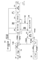
- FIG. 1 It is a block diagram which shows the structure of the image coding apparatus in Embodiment 1.
- FIG. 2 It is a block diagram which shows the structure of the image decoding apparatus in Embodiment 2.
- FIG. 1 is a block diagram showing an image coding apparatus of this embodiment.
- 101 is a terminal into which image data is input.
- 102 is a block division unit, which divides an input image into a plurality of basic blocks and outputs an image in units of basic blocks to the subsequent stage.
- a block having 128 ⁇ 128 pixels may be used as a basic block, or a block having 32 ⁇ 32 pixels may be used as a basic block.
- Reference numeral 103 denotes a quantization value correction information generation unit, which generates and outputs quantization value correction information, which is information about the correction processing of the quantization parameter that defines the quantization step.
- the method of generating the quantization value correction information is not particularly limited, but the user may input the quantization value correction information, or the image coding device may calculate from the characteristics of the input image.
- a preset value may be used as the initial value.
- the quantization parameter does not directly indicate the quantization step. For example, when the quantization parameter is 4, the quantization step (scaling factor) is designed to be 1. The larger the value of the quantization parameter, the larger the quantization step.
- the 104 is a prediction unit, which determines a method of dividing the image data in basic block units into sub-blocks. Then, the basic block is divided into subblocks having the determined shape and size. Then, intra-frame prediction, which is intra-frame prediction, inter-frame prediction, which is inter-frame prediction, and the like are performed in sub-block units to generate prediction image data. For example, the prediction unit 104 selects a prediction method to be performed for one subblock from intra-prediction, inter-prediction, and prediction coding that combines intra-prediction and inter-prediction, and performs the selected prediction. To generate predicted image data for the subblock. The prediction unit 104 also functions as a determination means for determining what kind of coding is to be performed based on a flag or the like.
- the prediction unit 104 calculates and outputs a prediction error from the input image data and the predicted image data. For example, the prediction unit 104 calculates the difference between each pixel value of the sub-block and each pixel value of the predicted image data generated by the prediction for the sub-block, and calculates it as a prediction error.
- the prediction unit 104 outputs information necessary for prediction together with a prediction error.
- the information required for prediction is, for example, information indicating a division state of a subblock, a prediction mode indicating a prediction method of the subblock, motion vector, and the like.
- the information necessary for this prediction is referred to as prediction information.
- prediction information when there are few types of colors (pixel values) used in the sub-block, it can be determined that compression can be performed more efficiently by using palette coding using a palette. This determination may be made by the image coding device or the user. When it is determined in this way, palette coding can be selected as a method for generating the predicted image data.
- a palette has one or more entries in which information indicating a color and an index for identifying the information indicating the color are associated with each other.
- palette flag a flag indicating that palette coding is used
- index indicating which color in the palette is used by each pixel is also output as prediction information.
- information indicating a color that does not exist in the palette (there is no corresponding entry) (hereinafter referred to as an escape value) is also output as prediction information.
- the prediction unit 104 can code a specific pixel in a subblock to be coded using palette coding using an escape value. That is, the prediction unit 104 can determine whether or not to use the escape value for each pixel. Coding with escape values is also called escape coding.
- Reference numeral 105 denotes a conversion / inverse quantization unit that performs orthogonal conversion (orthogonal conversion processing) of the prediction error in sub-block units to obtain a conversion coefficient representing each frequency component of the prediction error.
- the conversion / inverse quantization unit 105 is a conversion / quantization unit that further quantizes the conversion coefficient to obtain a residual coefficient (quantized conversion coefficient).
- Orthogonal conversion processing is not performed when conversion skip or palette coding is used.
- the function of performing orthogonal conversion and the function of performing quantization may be configured separately.
- the residual coefficient output from the conversion / quantization unit 105 is inversely quantized, the conversion coefficient is reproduced, and then inverse orthogonal conversion (inverse orthogonal conversion processing) is performed to reproduce the prediction error. It is a conversion unit. When conversion skip or palette coding is used, the inverse orthogonal conversion process is not performed. The process of reproducing (deriving) the orthogonal conversion coefficient in this way is referred to as inverse quantization.
- the function of performing inverse quantization and the function of performing inverse orthogonal conversion processing may be configured separately.
- 108 is a frame memory for storing the reproduced image data.
- the frame memory 108 is appropriately referred to to generate the prediction image data, and the reproduction image data is generated and output from the predicted image data and the input prediction error. ..
- the reproduced image is subjected to in-loop filter processing such as a deblocking filter and sample adaptive offset, and the filtered image is output.
- in-loop filter processing such as a deblocking filter and sample adaptive offset
- the residual coefficient output from the conversion / quantization unit 105 and the prediction information output from the prediction unit 104 are encoded to generate and output code data.
- the 111 is an integrated coding unit.
- the output from the quantization value correction information generation unit 103 is encoded to generate header code data. Further, a bit stream is generated and output together with the code data output from the coding unit 110.
- the information indicating the quantization parameter is also encoded in the bit stream.
- the information indicating the quantization parameter is information indicating the difference value between the quantization parameter to be encoded and another quantization parameter (for example, the quantization parameter of the previous subblock).
- the 112 is a terminal and outputs the bit stream generated by the integrated coding unit 111 to the outside.
- the moving image data is input in frame units (picture units), but a still image data for one frame may be input.
- the quantization value correction information generation unit 103 Prior to image coding, the quantization value correction information generation unit 103 generates the quantization value correction information used when correcting the quantization parameter in the subsequent stage when conversion skip or palette coding is used. ..
- the quantization value correction information generation unit 103 may generate the quantization value correction information at least when either conversion skip or palette coding is used. However, in any case, the amount of code can be further reduced by generating the quantization correction information.
- the quantization value correction information includes, for example, information indicating QPmin indicating the minimum quantization value (minimum QP value) when correcting the quantization parameter. For example, if the quantization parameter is smaller than this QPmin, it is corrected to be QPmin. A detailed explanation of how this quantization value correction information is used will be described later.
- the method of generating the quantization value correction information is not particularly limited, but the user may input (specify) the quantization value correction information, or the image coding device calculates the quantization value correction information from the characteristics of the input image.
- a predetermined initial value may be used.
- the initial value a value (for example, 4) indicating that the quantization step is 1 can be used.
- conversion skip or palette coding is used, even if the quantization step is less than 1, the image quality is the same as when the quantization step is 1, so setting QPmin to 4 uses conversion skip or palette coding. Suitable for cases.
- QPmin is used as the initial value, the quantization value correction information may be omitted. Further, as described later, when QPmin is set to a value other than the initial value, the difference value from the initial value may be used as the quantization value correction information.
- the quantization value correction information may be determined based on the implementation limitation when the prediction unit 104 determines whether or not to perform palette coding. Further, the quantization value correction information may be determined based on the implementation limitation when the conversion quantization unit 105 determines whether or not to perform orthogonal conversion.
- the generated quantization value correction information is input to the conversion / quantization unit 105, the inverse quantization / inverse conversion unit 106, and the integrated coding unit 111.
- the image data for one frame input from the terminal 101 is input to the block division unit 102.
- the block division unit 102 divides the input image data into a plurality of basic blocks, and outputs an image in basic block units to the prediction unit 104.
- the prediction unit 104 executes prediction processing on the image data input from the block division unit 102. Specifically, first, the subblock division that divides the basic block into smaller subblocks is determined.
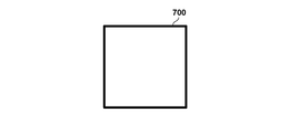
- FIGS. 7A to 7F show an example of the subblock division method.
- the 700 in the thick frame represents a basic block, and for the sake of simplicity, a 32 ⁇ 32 pixel configuration is used, and each quadrangle in the thick frame represents a subblock.
- FIG. 7B shows an example of a conventional square subblock division, in which a 32 ⁇ 32 pixel basic block is divided into four subblocks having a size of 16 ⁇ 16 pixels.
- FIGS. 7C to 7F show an example of rectangular subblock division.
- the basic block shows an example of division into two vertically long sub-blocks having a size of 16 ⁇ 32 pixels.
- FIG. 7C the basic block shows an example of division into two vertically long sub-blocks having a size of 16 ⁇ 32 pixels.
- the basic block is divided into two horizontally long rectangular sub-blocks having a size of 32 ⁇ 16 pixels. Further, in FIGS. 7E and 7F, the blocks are divided into three rectangular sub-blocks at a ratio of 1: 2: 1. In this way, not only the square but also the rectangular sub-block is used for the coding process.
- FIG. 7A which does not divide the basic block of 32 ⁇ 32 pixels, is used, but the sub-block division method is not limited to this.
- a quadtree division as shown in FIG. 7B, a ternary tree division as shown in FIGS. 7E and 7F, or a binary tree division as shown in FIGS. 7C and 7D may be used.
- the prediction unit 104 determines the prediction mode for each subblock to be processed (block to be encoded). Specifically, the prediction unit 104 sub-predicts intra-prediction using pixels encoded in the same frame as the frame including the sub-block to be processed, inter-prediction using pixels in different encoded frames, and the like. Determine as the prediction mode to use for each block.
- the prediction unit 104 generates prediction image data from the determined prediction mode and the encoded pixels, further generates a prediction error from the input image data and the predicted image data, and converts / quantizes the prediction error. It is output to unit 105.
- the prediction unit 104 outputs information such as subblock division and prediction mode as prediction information to the coding unit 110 and the image reproduction unit 107.
- palette coding can be selected instead of the prediction mode such as intra prediction or inter prediction.
- a palette flag indicating whether to use palette coding is output as prediction information.
- an index or escape value indicating color information included in the palette corresponding to each pixel is also output as prediction information.
- palette coding is not selected in the subblock, that is, if a prediction mode such as intra-prediction or inter-prediction is selected (for example, the value of the palette flag is 0), the palette flag is followed by other prediction information. Output the prediction error.
- a prediction mode such as intra-prediction or inter-prediction
- the conversion / quantization unit 105 performs orthogonal conversion processing and quantization processing on the prediction error output from the prediction unit 104. Specifically, first, it is determined whether or not orthogonal conversion processing is performed on the prediction error of the subblock using the prediction mode other than palette coding such as intra prediction and inter prediction.
- the prediction mode other than palette coding such as intra prediction and inter prediction.
- image coding for a natural image that is generated by capturing a landscape, a person, or the like with a camera.
- the prediction error is orthogonally converted, decomposed into frequency components, and quantized according to the human visual characteristics, so that the deterioration of image quality is not noticeable. It is possible to reduce the amount of data.
- the conversion / quantization unit 105 determines whether or not to perform orthogonal conversion for each color component (Y, Cb, Cr) of the subblock, and generates the determination result as conversion skip information. That is, the conversion skip information can be generated for each color component (Y, Cb, Cr). That is, it may be decided whether or not to skip the conversion for each color component. For example, conversion skip information for the luminance component (Y) and conversion skip information for the color difference components (Cb and Cr) may be generated.
- the orthogonal conversion process is performed on the prediction error corresponding to the color component and the orthogonal conversion coefficient is calculated. Generate. Then, the quantization process using the quantization parameter is performed to generate the residual coefficient.
- the method for determining the value of the quantization parameter itself used here is not particularly limited, but the user may input the quantization parameter, or an image coding device based on the characteristics of the input image (image complexity, etc.). May be calculated. Moreover, you may use the thing specified in advance as an initial value.
- the quantization parameter QP is calculated by the quantization parameter calculation unit (not shown) and input to the conversion / quantization unit 105.
- the orthogonal conversion coefficient of the luminance component (Y) of the subblock is quantized using this quantization parameter QP, and a residual coefficient is generated.
- the orthogonal conversion coefficient of the Cb component of the subblock is quantized using the quantization parameter QPcb in which the quantization parameter QP is adjusted for the Cb component, and a residual coefficient is generated.
- the orthogonal conversion coefficient of the Cr component of the subblock is quantized using the quantization parameter QPcr adjusted for the Cr component, and a residual coefficient is generated.
- the method for calculating QPcb and QPcr from this QP is not particularly limited, but a table for calculation may be prepared in advance. Further, the table used for calculating QPcb and QPcr may be separately encoded so that the same QPcb and QPcr can be calculated on the decoding side as well. When the table used for the calculation is separately encoded, it is encoded in the header portion of the bitstream sequence or the picture in the integrated coding unit 111 in the subsequent stage.
- the prediction is made using the corrected quantization parameter obtained by correcting the quantization parameter QP. Quantize the error and generate the residual coefficient. Specifically, the prediction error of the luminance component (Y) of the subblock is quantized using the QP'corrected by the above-mentioned QP, and a residual coefficient is generated. On the other hand, the prediction error of the Cb component of the subblock is quantized using the QPcb'corrected by the QPcb described above, and a residual coefficient is generated. Similarly, the prediction error of the Cr component of the subblock is quantized using QPcr'corrected by the above-mentioned QPcr to generate a residual coefficient.
- the residual coefficient and conversion skip information generated in this way are input to the inverse quantization / inverse conversion unit 106 and the coding unit 110.
- the escape value itself is quantized in order to limit the increase in the code amount for the pixel for which the escape value is set.
- the corrected quantization parameters QP', QPcb', QPcr'
- QP, QPcb, QPcr the quantization parameters
- the quantized escape value is input to the inverse quantization / inverse conversion unit 106 and the coding unit 110 in the same manner as the residual coefficient.
- the inverse quantization / inverse conversion unit 106 performs inverse quantization processing and inverse orthogonal conversion processing on the input residual coefficient.
- the inverse quantization process is performed on the residual coefficient of the subblock using the prediction mode other than palette coding such as intra prediction and inter prediction, and the orthogonal conversion coefficient is reproduced.
- Whether or not orthogonal conversion is applied to each color component of each subblock is determined based on the conversion skip flag input from the conversion / quantization unit 105.
- the conversion skip flag is 0, it indicates that the conversion skip is not used.
- the quantization parameter used at this time is the same as that of the conversion / quantization unit 105, and for the residual coefficient generated by performing the orthogonal conversion process, the above-mentioned quantization parameter (for each color component) QP, QPcb, QPcr) is used.
- the conversion skip flag is 1
- the above-mentioned correction quantization parameters QP', QPcb', QPcr' ) Is used.
- the residual coefficient generated by the orthogonal conversion process is inversely quantized using the quantization parameters (QP, QPcb, QPcr), and the prediction error is reproduced by further performing the inverse orthogonal transformation. ..
- the residual coefficient generated by skipping the conversion is inversely quantized using the corrected quantization parameters (QP', QPcb', QPcr'), and the prediction error is reproduced.
- the prediction error reproduced in this way is output to the image reproduction unit 107.
- the quantized escape value is dequantized using the corrected quantization parameters (QP', QPcb', QPcr'), and the escape value is reproduced.
- the reproduced escape value is output to the image reproduction unit 107.
- the image reproduction unit 107 when the palette flag input from the prediction unit 104 indicates that the subblock is not palette-encoded, the image reproduction unit 107 appropriately refers to the frame memory 108 based on other prediction information and predicts the image. To play. Then, the image data is reproduced from the reproduced predicted image and the reproduced predicted error input from the inverse quantization / inverse conversion unit 106, input to the frame memory 108, and stored. On the other hand, when it is shown that the subblock is palette-encoded, the image data is reproduced using an index or an escape value indicating which color in the palette each pixel input as prediction information uses. Then, it is input to the frame memory 108 and stored.
- the in-loop filter unit 109 reads the reproduced image from the frame memory 108 and performs in-loop filter processing such as a deblocking filter.
- in-loop filter processing the prediction mode of the prediction unit 104, the value of the quantization parameter used by the conversion / quantization unit 105, and the non-zero value in the processing subblock after quantization (hereinafter referred to as a significance coefficient). It is performed based on whether or not there exists and the subblock division information. Then, the filtered image is input to the frame memory 108 again and stored again.
- the coding unit 110 entropy-encodes the residual coefficient generated by the conversion / quantization unit 105 and the prediction information input from the prediction unit 104 in sub-block units to generate code data. Specifically, first, a palette flag indicating whether or not the subblock is palette-coded is encoded. When the subblock is not palette-encoded, 0 is entropy-encoded as a palette flag input as prediction information, and then other prediction information and residual coefficients are entropy-encoded to generate code data. On the other hand, when the subblock is palette-encoded, 1 is entropy-encoded as a palette flag, and then an index or escape value indicating which color in the palette is used by each pixel is encoded to obtain code data. Generate. The method of entropy coding is not particularly specified, but Golomb coding, arithmetic coding, Huffman coding, etc. can be used. The generated code data is output to the integrated coding unit 111.
- the integrated coding unit 111 encodes the quantization value correction information input from the quantization value correction information generation unit 103 and generates a quantization value correction information code.
- the coding method is not particularly specified, Golomb coding, arithmetic coding, Huffman coding, or the like can be used.
- 4 indicating the quantization step 1 is used as a reference (initial value), and the difference value between the reference 4 and the minimum QP value QPmin which is the quantization value correction information is Golomb-coded. To do. Since QPmin is set to 4 in this embodiment, the 1-bit code “0” obtained by Golomb coding 0, which is the difference value from the reference 4, is used as the quantization value correction information code.
- the code amount of the quantization value correction information can be minimized.
- the table is also encoded here. Further, these codes, code data input from the coding unit 110, and the like are multiplexed to form a bit stream. Eventually, the bitstream is output from terminal 112 to the outside.
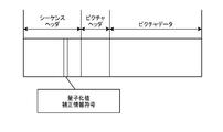
- FIG. 6A shows an example of a bit stream including the encoded quantization value correction information.
- the quantization control size information is included in any of the headers such as sequences and pictures as the quantization control size information code. In the present embodiment, as shown in FIG. B, it is included in the header portion of the sequence. However, the encoded position is not limited to this, and may be included in the header portion of the picture as shown in FIG. 6A.
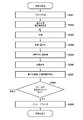
- FIG. 3 is a flowchart showing a coding process in the image coding apparatus according to the first embodiment.
- step S301 the block division unit 102 divides the input image for each frame into basic block units.
- step S302 the quantization value correction information generation unit 103 determines the quantization value correction information which is information about the correction processing of the quantization parameter.
- the quantized value correction information is encoded by the integrated coding unit 111.
- step S303 the prediction unit 104 performs prediction processing on the image data of the basic block unit generated in step S301, and generates prediction information such as subblock division and prediction mode, and prediction image data. Further, the prediction error is calculated from the input image data and the predicted image data. However, if there are few types of colors (pixel values) used in the sub-block and it is judged that compression can be performed more efficiently by using palette coding, palette coding can also be selected. The prediction unit 104 also generates a palette flag indicating whether or not the subblock is palette-coded.
- the conversion / quantization unit 105 first determines each color component (Y, Cb, Cr) of the prediction error calculated in step S303. It is determined whether or not the orthogonal conversion process is applied to the product. Then, conversion skip information is generated as the determination result. When it is determined that the orthogonal conversion process is performed on the color component, the orthogonal conversion is performed on the prediction error corresponding to the color component to generate the orthogonal conversion coefficient. Then, quantization is performed using the quantization parameters (QP, QPcb, QPcr) to generate a residual coefficient.
- the prediction error corresponding to the color component is quantized using the corrected quantization parameters (QP', QPcb', QPcr'). And generate a residual coefficient.
- the conversion / quantization unit 105 performs quantization using the corrected quantization parameters (QP', QPcb', QPcr') on the escape value, and quantizes the escape value. Generate a quantized escape value.
- step S305 the inverse quantization / inverse conversion unit 106 performs inverse quantization processing and inverse orthogonal conversion processing on the residual coefficient generated in step S304. Specifically, when a prediction mode other than palette coding is used, the inverse quantization / inverse conversion unit 106 first determines whether or not each color component of each subblock is orthogonally transformed in step S304. Judgment is made based on the conversion skip information generated in. Then, based on the determination result, the residual coefficient is subjected to inverse quantization processing.
- the quantization parameter used at this time is the same as that in step S304, and for the residual coefficient generated by performing the orthogonal conversion process, the above-mentioned quantization parameter (QP, QPcb, QPcr) is applied to each color component. ) Is used.
- the above-mentioned correction quantization parameters (QP', QPcb', QPcr') are used for each color component. That is, the residual coefficient generated by the orthogonal conversion process is inversely quantized using the quantization parameters (QP, QPcb, QPcr), and the prediction error is reproduced by further performing the inverse orthogonal transformation. ..
- the residual coefficient generated by skipping the conversion is inversely quantized using the corrected quantization parameters (QP', QPcb', QPcr'), and the prediction error is reproduced.
- the escape value quantized in step S304 is dequantized using the corrected quantization parameters (QP', QPcb', QPcr'), and the escape value is set. Reproduce.
- step S306 when the palette flag generated in step S303 indicates that the subblock is not palette-coded, the image reproduction unit 107 makes a prediction based on the prediction information generated in step S303. Play the image. Further, the image data is reproduced from the reproduced predicted image and the predicted error generated in step S305. On the other hand, when the palette flag indicates that the subblock is palette-coded, the image reproduction unit 107 uses an index or an escape value indicating which color in the palette each pixel uses in the image. Play the data.
- step S307 the coding unit 110 encodes the prediction information generated in step S303 and the residual coefficient generated in step S304 to generate code data. Specifically, first, a palette flag indicating whether or not the subblock is palette-coded is encoded. When the subblock is not palette-encoded, 0 is entropy-encoded as a palette flag input as prediction information, and then other prediction information and residual coefficients are entropy-encoded to generate code data.
- 1 is entropy-encoded as a palette flag, and then an index or escape value indicating which color in the palette is used by each pixel is encoded to obtain code data. Generate. A bit stream is generated including other code data.
- step S308 the image coding apparatus determines whether or not the coding of all the basic blocks in the frame is completed, and if so, proceeds to step S309, and if not, the next basic block. Return to step S303.
- step S309 the in-loop filter unit 109 performs in-loop filter processing on the image data reproduced in step S306, generates a filtered image, and ends the processing.
- the quantization value correction information is generated particularly in step S302, and in steps S304 and S305, the quantization parameter corrected based on the quantization value correction information is used, so that an unnecessary code amount is used. Can be prevented from increasing. As a result, the amount of data in the entire generated bit stream can be suppressed and the coding efficiency can be improved.
- the quantization parameters corresponding to each color component such as Y, Cb, and Cr are corrected, but the present invention is not limited to this.
- another quantization parameter QPcbcr is used for the color difference residual coefficient common coding that collectively encodes the residual coefficients of Cb and Cr examined in VVC, but it may be applied to this.
- the prediction error in which the conversion is skipped and the color difference residual coefficient is commonly coded may be quantized by using the corrected quantization parameter QPcbcr'.
- the quantization step is not unnecessarily reduced, the processing load can be reduced.
- the quantization value is uniformly corrected based on a single quantization value correction information, but the quantization is performed separately for each color component or for conversion skip and palette coding.
- the configuration may use value correction information.
- QPmin, QPminY for luminance, QPmincb for Cb, and QPmincr for Cr may be individually defined, and individual quantization value corrections may be performed according to color components. This makes it possible to correct the optimum quantization parameter according to the bit depth, especially when the bit depth differs depending on the color component.
- QPmin QPminTS for conversion skip and QPminPLT for palette coding may be individually defined, and different quantization value corrections may be performed according to each case. This makes it possible to correct the optimum quantization parameter according to each case, especially when the bit depth of the input pixel value and the bit depth used in the palette coding are different.
- the quantization parameter may be corrected when either conversion skip or palette coding is used. Even so, the possibility that the code amount is unnecessarily increased can be reduced. However, in any case, if the quantization parameter is corrected, the possibility that the code amount is unnecessarily increased can be further reduced.
- FIG. 2 is a block diagram showing a configuration of an image decoding device according to a second embodiment of the present invention.
- decoding of the coded data generated in the first embodiment will be described as an example.
- the image decoding device basically performs the reverse operation of the image coding device of the first embodiment.
- 201 is a terminal for inputting an encoded bit stream.
- the separation / decoding unit 202 is a separation / decoding unit, which separates information related to decoding processing and code data related to coefficients from the bit stream and decodes it. Further, the separation / decoding unit 202 decodes the code data existing in the header unit of the bit stream. In the present embodiment, the quantized value correction information is reproduced (decoded) and output to the subsequent stage.
- the separation / decoding unit 202 performs the reverse operation of the integrated coding unit 111 of FIG.
- Reference numeral 203 denotes a decoding unit, which decodes the code data output from the separation decoding unit 202 and reproduces the residual coefficient and the prediction information.
- Reference numeral 204 denotes an inverse quantization / inverse conversion unit. Similar to the reference reference numeral 106 in FIG. 1, a residual coefficient is input in subblock units, inverse quantization is performed to obtain a conversion coefficient, and inverse orthogonal conversion is further performed. Reproduce the prediction error. However, when conversion skip or palette coding is used, the inverse orthogonal conversion process is not performed. Further, the function of performing inverse quantization and the function of performing inverse orthogonal transformation may be configured separately.
- the inverse quantization / inverse conversion unit 204 also functions as a determination means for determining what kind of coding is to be performed based on a flag or the like.
- the information indicating the quantization parameter is also decoded from the bit stream by the decoding unit 203.
- the information indicating the quantization parameter is information indicating the difference value between the target quantization parameter and another quantization parameter (for example, the quantization parameter of the previous subblock).
- the other quantization parameter may be information indicating the difference value between the average value of the plurality of quantization parameters of the plurality of other subblocks and the target quantization parameter.
- the inverse quantization / inverse conversion unit 204 derives the target quantization parameter by, for example, adding this difference value to another quantization parameter.
- the quantization parameter may be derived by adding the difference value to the separately decoded initial value. By correcting the quantization parameter derived in this way, the above-mentioned corrected quantization parameter can be derived.
- 206 is a frame memory. Stores the image data of the reproduced picture.
- the frame memory 206 is appropriately referred to to generate the prediction image data.
- a prediction method such as intra-prediction or inter-prediction is used as in the prediction unit 104 of the first embodiment. Further, as described above, a prediction method that combines intra-prediction and inter-prediction may be used. Further, as in the first embodiment, the prediction process is performed in sub-block units. Then, the reproduced image data is generated and output from the predicted image data and the predicted error reproduced by the inverse quantization / inverse conversion unit 204.
- 207 is an in-loop filter unit. Similar to reference numeral 109 in FIG. 1, the reproduced image is subjected to in-loop filter processing such as a deblocking filter, and the filtered image is output.
- in-loop filter processing such as a deblocking filter
- the 208 is a terminal and outputs the reproduced image data to the outside.
- the reproduced image is output to, for example, an external display device or the like.
- the image decoding operation in the image decoding device will be described below.
- the bitstream generated in the first embodiment is decoded.
- the bit stream input from the terminal 201 is input to the separation / decoding unit 202.
- the decoding unit 202 separates the information related to the decoding process and the code data related to the coefficient from the bit stream, and decodes the code data. Further, the separation / decoding unit 202 decodes the code data existing in the header unit of the bit stream. Specifically, the quantization value correction information is reproduced (decoded).
- the quantization value correction information code is extracted from the sequence header of the bit stream shown in FIG. 6B and decoded. Specifically, the Golomb-coded 1-bit code "0" in the first embodiment is Golomb-coded to obtain 0, and the reference 4 is added to 0 to obtain 4, which is the quantization value correction information.
- the quantization value correction information obtained in this way is output to the inverse quantization / inverse conversion unit 204. Subsequently, the code data of the basic block unit of the picture data is reproduced, and this is also output to the decoding unit 203.
- the decoding unit 203 decodes the code data and reproduces the residual coefficient, the prediction information, and the quantization parameter.
- the reproduced residual coefficient and quantization parameter are output to the inverse quantization / inverse conversion unit 204, and the reproduced prediction information is output to the image reproduction unit 205.
- the reproduced prediction information includes information on subblock division in the basic block, palette flags, conversion skip information, and the like.
- the inverse quantization / inverse conversion unit 204 performs inverse quantization and inverse orthogonal conversion on the input residual coefficient. Specifically, first, it is determined whether or not the subblock to be decoded is palette-encoded based on the palette flag input from the decoding unit 203.
- the residual coefficient of the subblock is subjected to inverse quantization processing to reproduce the orthogonal conversion coefficient.
- the quantization parameter used for the inverse quantization processing varies depending on whether or not the residual coefficient corresponding to each color component is subjected to the orthogonal conversion processing, but whether or not the orthogonal conversion processing is performed. Determines based on the conversion skip information input from the decoding unit 203.
- the quantization parameters used for this inverse quantization processing are the same as those of the inverse quantization / inverse conversion unit 106 of the first embodiment, and for the residual coefficient generated by the orthogonal transformation processing, each color component is charged.
- the above-mentioned quantization parameters QP, QPcb, QPcr
- the above-mentioned correction quantization parameters (QP', QPcb', QPcr') are used for each color component. That is, the residual coefficient generated by the orthogonal conversion process is inversely quantized using the quantization parameters (QP, QPcb, QPcr), and further subjected to the inverse orthogonal transformation to reproduce the prediction error.
- the prediction information reproduced in this way is output to the image reproduction unit 205.
- the corrected quantization parameters QP', QPcb', QPcr'
- the corrected quantization parameters (QP', QPcb', QPcr') are used for the quantized escape value input from the decoding unit 203. Dequantize and regenerate the escape value.
- the reproduced escape value is output to the image reproduction unit 205.
- the values reproduced using other than the escape values (color values included in the palette indicated by the index) in the subblock are also output to the image reproduction unit 205 together with the escape values.
- the predicted image is composed of the values output to the image reproduction unit 205.
- the image reproduction unit 205 when the palette flag input from the decoding unit 203 indicates that the subblock is not palette-encoded, the image reproduction unit 205 appropriately refers to the frame memory 206 based on other prediction information and predicts the image. To play.
- the image data is reproduced from the predicted image and the prediction error input from the inverse quantization / inverse conversion unit 204, input to the frame memory 206, and stored. Specifically, the image reproduction unit 205 reproduces the image data by adding the predicted image and the prediction error.
- the palette flag indicates that the subblock is palette-coded
- an index indicating which color in the palette is used by each pixel input as prediction information, a reproduced escape value, etc.
- the image data is reproduced using. Then, it is input to the frame memory 206 and stored.
- the stored image data is used as a reference when making a prediction.
- the in-loop filter unit 207 reads the reproduced image from the frame memory 206 and performs in-loop filter processing such as a deblocking filter and a sample adaptive offset. Then, the filtered image is again frame memory 20. It is input to 6.
- the reproduced image stored in the frame memory 206 is finally output from the terminal 208 to the outside.
- FIG. 4 is a flowchart showing an image decoding process in the image decoding apparatus according to the second embodiment.
- step S401 the separation / decoding unit 202 separates the bitstream into information related to decoding processing and code data related to coefficients, decodes the code data of the header portion, and reproduces the quantization value correction information.
- step S402 the decoding unit 203 decodes the code data separated in step S401 and reproduces the residual coefficient, the prediction information, and the quantization parameter. More specifically, first, a palette flag indicating whether or not the subblock to be decoded is palette-coded is reproduced. When the reproduced palette flag indicates 0, that is, when the subblock is not palette-coded, other prediction information, the residual coefficient, and the conversion skip information are subsequently reproduced. On the other hand, when the reproduced palette flag indicates 1, that is, when the subblock is palette-coded, an index indicating which color in the palette each pixel uses, a quantized escape value, etc. To play.
- step S403 when the subblock to be decoded is not palette-coded, the inverse quantization / inverse conversion unit 204 first determines whether or not each color component of the subblock is orthogonally transformed. The determination is made based on the conversion skip information reproduced in S402. Then, based on the determination result, the residual coefficient is subjected to inverse quantization processing.
- the quantization parameter used at this time is the same as that of step S305 of the first embodiment, and for the residual coefficient generated by performing the orthogonal conversion process, the above-mentioned quantization parameter (QP) is applied to each color component. , QPcb, QPcr).
- the above-mentioned correction quantization parameters (QP', QPcb', QPcr') are used for each color component. That is, the residual coefficient generated by the orthogonal conversion process is inversely quantized using the quantization parameters (QP, QPcb, QPcr), and the prediction error is reproduced by further performing the inverse orthogonal transformation. ..
- the residual coefficient generated by skipping the conversion is inversely quantized using the corrected quantization parameters (QP', QPcb', QPcr'), and the prediction error is reproduced.
- the quantized escape value reproduced in step S402 is dequantized using the corrected quantization parameters (QP', QPcb', QPcr'). Play the escape value.
- step S404 when the palette flag reproduced in step S402 indicates that the subblock is not palette-coded, the image reproduction unit 205 reproduces the predicted image based on the prediction information generated in step S402. To do. Further, the image data is reproduced from the reproduced predicted image and the predicted error generated in step S403.
- the image reproduction unit 205 uses an index, an escape value, or the like indicating which color in the palette each pixel uses in the image. Play the data.
- step S405 the image decoding device determines whether or not all the basic blocks in the frame have been decoded, and if so, proceeds to step S406, otherwise the next basic block is targeted. Return to step S402.
- step S406 the in-loop filter unit 207 performs in-loop filter processing on the image data reproduced in step S404, generates a filtered image, and ends the processing.
- the bit stream in which the unnecessary increase in the code amount is suppressed is decoded. Can be done.
- the bit stream in which the quantization control size information is included in the sequence header portion is decoded, but the coding position of the information is not limited to this. As shown in FIG. 6A, it may be encoded at the picture header portion of the image, or it may be encoded at another position.
- the quantization parameters corresponding to each color component such as Y, Cb, and Cr are corrected, but the present invention is not limited to this.
- the conversion is skipped and the color difference residual coefficient is commonly encoded.
- the residual coefficient is inversely quantized using the corrected quantization parameter QPcbcr'calculated by the above equation (4). May be good.
- QPcbcr'calculated by the above equation (4) May be good.
- it is possible to correct the appropriate quantization parameter even for the residual coefficient that is skipped and commonly coded for the color difference residual coefficient, and decodes the bit stream that prevents an unnecessary increase in the amount of code. can do.
- the quantization step is not unnecessarily reduced, the processing load can be reduced.
- the quantization value is uniformly corrected based on a single quantization value correction information, but the quantization is performed separately for each color component or for conversion skip and palette coding.
- the configuration may use value correction information.
- QPmin, QPminY for luminance, QPmincb for Cb, and QPmincr for Cr may be individually defined, and individual quantization value corrections may be performed according to color components. This makes it possible to correct the optimum quantization parameter according to the bit depth, especially when the bit depth differs depending on the color component.
- QPmin QPminTS for conversion skip and QPminPLT for palette coding may be individually defined, and different quantization value corrections may be performed according to each case. This makes it possible to correct the optimum quantization parameter according to each case, especially when the bit depth of the output pixel value and the bit depth used in the palette coding are different.
- the quantization parameter may be corrected when either conversion skip or palette coding is used. Even so, the possibility that the code amount is unnecessarily increased can be reduced. However, in any case, if the quantization parameter is corrected, the possibility that the code amount is unnecessarily increased can be further reduced.
- FIGS. 1 and 2 Each of the processing units shown in FIGS. 1 and 2 has been described in the above embodiment as being configured by hardware. However, the processing performed by each processing unit shown in these figures may be configured by a computer program.
- FIG. 5 is a block diagram showing a configuration example of computer hardware applicable to the image coding device and the image decoding device according to each of the above embodiments.
- the CPU 501 controls the entire computer using computer programs and data stored in the RAM 502 and ROM 503, and executes each of the above-described processes as performed by the image processing device according to each of the above embodiments. That is, the CPU 501 functions as each processing unit shown in FIGS. 1 and 2. It should be noted that various hardware processors other than the CPU can also be used.
- the RAM 502 has an area for temporarily storing computer programs and data loaded from the external storage device 506, data acquired from the outside via the I / F (interface) 507, and the like. Further, the RAM 502 has a work area used by the CPU 501 when executing various processes. That is, the RAM 502 can be allocated as a frame memory, for example, or various other areas can be provided as appropriate.
- the ROM 503 stores the setting data of this computer, the boot program, and the like.
- the operation unit 504 is composed of a keyboard, a mouse, and the like, and can be operated by a user of the computer to input various instructions to the CPU 501.
- the display unit 505 displays the processing result by the CPU 501.
- the output unit 505 is composed of, for example, a liquid crystal display.
- the external storage device 506 is a large-capacity information storage device typified by a hard disk drive device.
- the external storage device 506 stores an OS (operating system) and a computer program for realizing the functions of the respective parts shown in FIGS. 1 and 2 in the CPU 501. Further, each image data as a processing target may be stored in the external storage device 506.
- the computer programs and data stored in the external storage device 506 are appropriately loaded into the RAM 502 according to the control by the CPU 501, and are processed by the CPU 501.
- a network such as a LAN or the Internet, or other devices such as a projection device or a display device can be connected to the I / F 507, and the computer acquires and sends various information via the I / F 507. Can be done.
- Reference numeral 508 is a bus connecting the above-mentioned parts.
- the operation having the above configuration is controlled by the CPU 501 playing a central role in the operation described in the above flowchart.
- the present invention supplies a program that realizes one or more functions of the above-described embodiment to a system or device via a network or storage medium, and one or more processors in the computer of the system or device reads and executes the program. It is also possible to realize the processing. It can also be realized by a circuit (for example, ASIC) that realizes one or more functions.
- a circuit for example, ASIC
- the computer program code read from the storage medium is written to the memory provided in the function expansion card inserted in the computer or the function expansion unit connected to the computer. Then, based on the instruction of the code of the computer program, the function expansion card, the CPU provided in the function expansion unit, or the like performs a part or all of the actual processing to realize the above-mentioned function.
Landscapes
- Engineering & Computer Science (AREA)
- Multimedia (AREA)
- Signal Processing (AREA)
- Physics & Mathematics (AREA)
- Discrete Mathematics (AREA)
- General Physics & Mathematics (AREA)
- Compression Or Coding Systems Of Tv Signals (AREA)
Abstract
The purpose of the present invention is to adaptively correct a quantization parameter used for a quantization process and reduce the possibility of unnecessary increasing of a code amount. To this end, an image encoding device according to the present invention: encodes a block to be encoded by using a second quantization parameter obtained by correcting a first quantization parameter, when the block to be encoded is determined to be predictively encoded and the coefficient of each color component of the block to be encoded is not determined to be orthogonally transformed; and encodes the block to be encoded by using the second quantization parameter, when the block to be encoded is determined to be palette-encoded and pixels inside the block to be encoded are determined to be escape-encoded. Here, the present invention derives the second quantization parameter by performing prescribed determination on the basis of the first quantization parameter and a prescribed value, and correcting the first quantization parameter according to the result of the prescribed determination.
Description
本発明は画像符号化装置、画像符号化方法、及びプログラム、画像復号装置、画像復号方法、及びプログラムに関する。
The present invention relates to an image coding device, an image coding method, and a program, an image decoding device, an image decoding method, and a program.
動画像の圧縮符号化方式として、HEVC(High Efficiency Video Coding)符号化方式(以下、HEVCと記す)が知られている。
As a compression coding method for moving images, a HEVC (High Efficiency Video Coding) coding method (hereinafter referred to as HEVC) is known.
また、近年、HEVCの後継として、さらに高効率な符号化方式の国際標準化を行う活動が開始され、JVET(Joint Video Experts Team)がISO・IECとITU-Tの間で設立された。このJVETにて、HEVCの後継の符号化方式であるVVC(Versatile Video Coding)符号化方式(以下、VVC)の標準化が進められている。
In recent years, as a successor to HEVC, activities to carry out international standardization of more efficient coding methods have been started, and JVET (Joint Video Experts Team) has been established between ISO / IEC and ITU-T. In this JVET, the standardization of the VVC (Versatile Video Coding) coding method (hereinafter referred to as VVC), which is the successor coding method of HEVC, is being promoted.
これらの符号化方式では、自然画ではない人工的に作成された画像に対する符号化効率向上のため、パレット符号化と呼ばれる方式が検討されている。これは、画像を表す代表的な色を予め決定し、入力された画素の値をこの代表色を示すインデックスを用いて符号化する技術となっている。特開2016-103804(特許文献1)では、このパレット符号化に用いられる量子化パラメータを補正する技術が開示されている。
In these coding methods, a method called palette coding is being studied in order to improve the coding efficiency of artificially created images that are not natural images. This is a technique in which a representative color representing an image is determined in advance, and the value of the input pixel is encoded by using an index indicating the representative color. Japanese Patent Application Laid-Open No. 2016-103804 (Patent Document 1) discloses a technique for correcting the quantization parameter used for this palette coding.
ここで、HEVCやVVCにおいては、量子化処理に用いられる量子化パラメータが4の時、量子化ステップ(Scaling factor)が1となるように設計されている。すなわち量子化パラメータが4の時に量子化の前と後とで値が変化しないように設計されている。言い換えると、量子化パラメータが4よりも大きい場合、量子化ステップが1よりも大きくなり、量子化後の値は元の値より小さくなる。反対に量子化パラメータが4よりも小さい場合、量子化ステップが1よりも小さい小数の値となり、量子化後の値は元の値より大きくなり、結果として階調性を高める効果がある。通常の直交変換を用いた符号化処理の場合、量子化パラメータを4より小さくすると、階調性が高まるため、量子化パラメータが4の時よりも圧縮後の画質を向上させる効果がある。一方で、直交変換を用いない符号化処理の場合には、階調性を高めても圧縮後の画質は向上せず、符号量が増大するといった問題が生じている。
Here, in HEVC and VVC, when the quantization parameter used for the quantization process is 4, the quantization step (scaling factor) is designed to be 1. That is, when the quantization parameter is 4, the value does not change before and after the quantization. In other words, if the quantization parameter is greater than 4, the quantization step will be greater than 1 and the quantized value will be smaller than the original value. On the contrary, when the quantization parameter is smaller than 4, the quantization step becomes a decimal value smaller than 1, and the value after quantization becomes larger than the original value, and as a result, there is an effect of improving the gradation. In the case of coding processing using ordinary orthogonal transformation, if the quantization parameter is smaller than 4, the gradation property is improved, so that there is an effect of improving the image quality after compression as compared with the case where the quantization parameter is 4. On the other hand, in the case of coding processing that does not use orthogonal conversion, there is a problem that the image quality after compression does not improve even if the gradation property is improved, and the amount of code increases.
本発明は上述した課題を解決するためになされたものであり、量子化パラメータを適応的に補正することで不必要に符号量が増加することを抑制する技術を提供する。
The present invention has been made to solve the above-mentioned problems, and provides a technique for suppressing an unnecessary increase in the amount of code by adaptively correcting the quantization parameter.
前述の問題点を解決するため、本発明の画像符号化装置は以下の構成を有する。すなわち、画像を複数のブロックに分割し、分割されたブロックごとに符号化してビットストリームを生成する画像符号化装置において、前記符号化対象のブロックを予測符号化するか、パレット符号化するかを判定する第1の判定手段と、前記第1の判定手段によって前記符号化対象のブロックをパレット符号化すると判定した場合に、前記符号化対象のブロック内の画素をエスケープ符号化するか否かを判定する第2の判定手段と、前記第1の判定手段によって前記符号化対象のブロックを予測符号化すると判定した場合に、前記符号化対象のブロックの各色成分の係数に対し、直交変換処理を施すか否かを判定する第3の判定手段と、前記第1の判定手段によって前記符号化対象のブロックを予測符号化すると判定した場合であって、前記第3の判定手段によって前記符号化対象のブロックの各色成分の係数に対し直交変換処理を施すと判定した場合、前記符号化対象のブロックの各色成分の係数に対応する第1の量子化パラメータを用いて前記符号化対象のブロックを符号化し、前記第1の判定手段によって前記符号化対象のブロックを予測符号化すると判定した場合であって、前記第3の判定手段によって前記符号化対象のブロックの各色成分の係数に対し直交変換処理を施さないと判定した場合、前記第1の量子化パラメータを補正することで得られる第2の量子化パラメータを用いて、前記符号化対象のブロックを符号化し、前記第1の判定手段によって前記符号化対象のブロックをパレット符号化すると判定した場合であって、前記第2の判定手段によって前記符号化対象のブロックのブロック内の画素をエスケープ符号化すると判定した場合、前記第2の量子化パラメータを用いて前記符号化対象のブロックを符号化する符号化手段とを有し、前記符号化手段は、前記第1の量子化パラメータと所定の値に基づく所定の判定を行い、当該所定の判定の判定結果に応じて前記第1の量子化パラメータを補正することで、前記第2の量子化パラメータを導出する。
In order to solve the above-mentioned problems, the image coding apparatus of the present invention has the following configuration. That is, in an image coding apparatus that divides an image into a plurality of blocks and encodes each divided block to generate a bit stream, whether the block to be encoded is predictively encoded or palette-encoded is determined. When the first determination means for determination and the first determination means determine that the block to be encoded is pallet-encoded, whether or not to escape-encode the pixels in the block to be encoded is determined. When it is determined by the second determination means for determination and the first determination means that the block to be coded is to be predictively coded, the orthogonal conversion process is performed on the coefficients of each color component of the block to be coded. When it is determined by the third determination means for determining whether or not to apply and the first determination means that the block to be encoded is to be predictively encoded, the coding target is determined by the third determination means. When it is determined that the orthogonal conversion process is performed on the coefficient of each color component of the block, the block to be coded is coded using the first quantization parameter corresponding to the coefficient of each color component of the block to be coded. In the case where it is determined by the first determination means that the block to be encoded is to be predicted and encoded, the third determination means performs orthogonal conversion processing on the coefficients of each color component of the block to be encoded. When it is determined that the above-mentioned is not performed, the block to be encoded is encoded by using the second quantization parameter obtained by correcting the first quantization parameter, and the first determination means is used to encode the block. When it is determined that the block to be encoded is pallet-encoded, and when it is determined by the second determination means that the pixels in the block to be encoded are escape-coded, the second quantization is performed. It has a coding means that encodes the block to be coded using parameters, and the coding means makes a predetermined determination based on the first quantization parameter and a predetermined value, and the predetermined value. The second quantization parameter is derived by correcting the first quantization parameter according to the determination result of the determination.
また、本発明の画像復号装置は以下の構成を有する。すなわち、画像を符号化して生成されたビットストリームを復号する画像復号装置であって、当該ビットストリームに含まれる、前記画像内の復号対象のブロックに対応する符号化データを復号する画像復号装置であって、前記復号対象のブロックが予測符号化されているか、パレット符号化されているかを判定する第1の判定手段と、前記第1の判定手段によって前記復号対象のブロックがパレット符号化されていると判定された場合に、前記復号対象のブロック内の画素がエスケープ符号化されているか否かを判定する第2の判定手段と、前記第1の判定手段によって前記復号対象のブロックが予測符号化されていると判定された場合に、前記復号対象のブロックの各色成分の残差係数が直交変換処理を施されているか、直交変換処理を施されていないかを判定する第3の判定手段と、前記第1の判定手段によって前記復号対象のブロックが予測符号化されていると判定した場合であって、前記第3の判定手段によって前記復号対象のブロックの各色成分の残差係数が直交変換処理を施されていると判定された場合、前記ビットストリームから復号される情報に基づいて前記復号対象のブロックの各色成分の残差係数に対応する第1の量子化パラメータを導出し、その第1の量子化パラメータを用いて前記復号対象のブロックを復号し、前記第1の判定手段によって前記復号対象のブロックが予測符号化されていると判定した場合であって、前記第3の判定手段によって前記復号対象のブロックの各色成分の残差係数が直交変換処理を施されていないと判定された場合、前記ビットストリームから復号される情報に基づいて前記復号対象のブロックに対応する第1の量子化パラメータを導出し、その第1の量子化パラメータを補正することで得られる第2の量子化パラメータを用いて、前記復号対象のブロックを復号し、前記第1の判定手段によって前記復号対象のブロックがパレット符号化されていると判定された場合であって、前記第2の判定手段によって前記復号対象のブロックのブロック内の画素がエスケープ符号化されていると判定された場合、前記第2の量子化パラメータを用いて前記復号対象のブロックを復号する復号手段とを有し、前記復号手段は、前記第1の量子化パラメータと所定の値に基づく所定の判定を行い、当該所定の判定の判定結果に応じて前記第1の量子化パラメータを補正することで、前記第2の量子化パラメータを導出する。
Further, the image decoding device of the present invention has the following configuration. That is, it is an image decoding device that decodes a bit stream generated by encoding an image, and is an image decoding device that decodes the coded data included in the bit stream and corresponding to the block to be decoded in the image. Therefore, the block to be decoded is pallet-encoded by the first determining means for determining whether the block to be decoded is predictively encoded or pallet-encoded, and the first determining means. When it is determined that the data is present, the second determination means for determining whether or not the pixels in the block to be decoded are escape-encoded, and the first determination means predict the block to be decoded. A third determination means for determining whether the residual coefficient of each color component of the block to be decoded is subjected to orthogonal conversion processing or not subjected to orthogonal conversion processing when it is determined that the data is quantized. When it is determined by the first determination means that the block to be decoded is predictively encoded, the residual coefficient of each color component of the block to be decoded is orthogonal by the third determination means. When it is determined that the conversion process has been performed, the first quantization parameter corresponding to the residual coefficient of each color component of the block to be decoded is derived based on the information decoded from the bit stream, and the quantization parameter is derived. When the block to be decoded is decoded using the first quantization parameter and it is determined by the first determination means that the block to be decoded is predictively encoded, the third determination is made. When it is determined by the means that the residual coefficient of each color component of the block to be decoded has not been subjected to the orthogonal conversion process, the first unit corresponding to the block to be decoded is based on the information decoded from the bit stream. The block to be decoded is decoded using the second quantization parameter obtained by deriving the quantization parameter of the above and correcting the first quantization parameter, and the decoding is performed by the first determination means. When it is determined that the target block is palette-encoded and the pixels in the block of the decoding target block are determined to be escape-encoded by the second determination means, the above-mentioned It has a decoding means that decodes the block to be decoded using the second quantization parameter, and the decoding means makes a predetermined determination based on the first quantization parameter and a predetermined value, and the predetermined value. By correcting the first quantization parameter according to the judgment result of the judgment of , The second quantization parameter is derived.
本発明のその他の特徴及び利点は、添付図面を参照とした以下の説明により明らかになるであろう。なお、添付図面においては、同じ若しくは同様の構成には、同じ参照番号を付す。
Other features and advantages of the present invention will be clarified by the following description with reference to the accompanying drawings. In the attached drawings, the same or similar configurations are designated by the same reference numbers.
本発明により、量子化パラメータを適応的に補正することで不必要に符号量が増加してしまう可能性を低減することができる。
According to the present invention, it is possible to reduce the possibility that the code amount is unnecessarily increased by adaptively correcting the quantization parameter.
添付図面は明細書に含まれ、その一部を構成し、本発明の実施の形態を示し、その記述と共に本発明の原理を説明するために用いられる。
実施形態1における画像符号化装置の構成を示すブロック図である。
実施形態2における画像復号装置の構成を示すブロック図である。
実施形態1に係る画像符号化装置における画像符号化処理を示すフローチャートである。
実施形態2に係る画像復号装置における画像復号処理を示すフローチャートである。
各実施形態における画像符号化装置及び画像復号装置に適用可能なコンピュータのハードウェア構成例を示すブロック図である。
実施形態1によって生成され、実施形態2によって復号されるビットストリーム構造の一例を示す図である。
実施形態1によって生成され、実施形態2によって復号されるビットストリーム構造の一例を示す図である。
実施形態で用いられるサブブロック分割の一例を示す図である。
実施形態で用いられるサブブロック分割の一例を示す図である。
実施形態で用いられるサブブロック分割の一例を示す図である。
実施形態で用いられるサブブロック分割の一例を示す図である。
実施形態で用いられるサブブロック分割の一例を示す図である。
実施形態で用いられるサブブロック分割の一例を示す図である。
The accompanying drawings are included in the specification and are used to form a part thereof, show embodiments of the present invention, and explain the principles of the present invention together with the description thereof.
It is a block diagram which shows the structure of the image coding apparatus in Embodiment 1. FIG. It is a block diagram which shows the structure of the image decoding apparatus in Embodiment 2. It is a flowchart which shows the image coding process in the image coding apparatus which concerns on Embodiment 1. It is a flowchart which shows the image decoding process in the image decoding apparatus which concerns on Embodiment 2. It is a block diagram which shows the hardware configuration example of the computer applicable to the image coding apparatus and the image decoding apparatus in each embodiment. It is a figure which shows an example of the bit stream structure generated by Embodiment 1 and decoded by Embodiment 2. It is a figure which shows an example of the bit stream structure generated by Embodiment 1 and decoded by Embodiment 2. It is a figure which shows an example of the sub-block division used in an embodiment. It is a figure which shows an example of the sub-block division used in an embodiment. It is a figure which shows an example of the sub-block division used in an embodiment. It is a figure which shows an example of the sub-block division used in an embodiment. It is a figure which shows an example of the sub-block division used in an embodiment. It is a figure which shows an example of the sub-block division used in an embodiment.
本発明の実施の形態を、添付の図面に基づいて説明する。なお、以下の実施形態において示す構成は一例であり、本発明は以下の実施形態で説明する構成に限定されるものではない。なお、基本ブロックやサブブロックといった呼称は、各実施形態において便宜的に用いている呼称であり、その意味が変わらない範囲で、適宜、他の呼称を用いてもよい。例えば、基本ブロックやサブブロックは、基本ユニットやサブユニットと称されてもよいし、単にブロックやユニットと称されてもよい。
An embodiment of the present invention will be described with reference to the accompanying drawings. The configuration shown in the following embodiments is an example, and the present invention is not limited to the configurations described in the following embodiments. It should be noted that the names such as basic block and sub-block are names used for convenience in each embodiment, and other names may be used as appropriate as long as their meanings do not change. For example, a basic block or subunit may be referred to as a basic unit or subunit, or may simply be referred to as a block or unit.
<実施形態1>
以下、本発明の実施形態を、図面を用いて説明する。 <Embodiment 1>
Hereinafter, embodiments of the present invention will be described with reference to the drawings.
以下、本発明の実施形態を、図面を用いて説明する。 <Embodiment 1>
Hereinafter, embodiments of the present invention will be described with reference to the drawings.
図1は本実施形態の画像符号化装置を示すブロック図である。図1において、101は画像データが入力される端子である。
FIG. 1 is a block diagram showing an image coding apparatus of this embodiment. In FIG. 1, 101 is a terminal into which image data is input.
102はブロック分割部であり、入力画像を複数の基本ブロックに分割し、基本ブロック単位の画像を後段に出力する。例えば、128×128画素のブロックを基本ブロックとしてもよいし、32×32画素のブロックを基本ブロックとしてもよい。
102 is a block division unit, which divides an input image into a plurality of basic blocks and outputs an image in units of basic blocks to the subsequent stage. For example, a block having 128 × 128 pixels may be used as a basic block, or a block having 32 × 32 pixels may be used as a basic block.
103は量子化値補正情報生成部であり、量子化ステップを規定する量子化パラメータの補正処理についての情報である、量子化値補正情報を生成し、出力する。量子化値補正情報の生成方法については特に限定しないが、ユーザが量子化値補正情報を指定する入力を行ってもよいし、入力画像の特性から画像符号化装置が算出してもよいし、初期値としてあらかじめ指定されたものを使用してもよい。なお、量子化パラメータは量子化ステップを直接的に示すのではなく、例えば、量子化パラメータが4の時、量子化ステップ(Scaling factor)が1となるように設計されている。量子化パラメータの値が大きければ、量子化ステップも大きくなる。
Reference numeral 103 denotes a quantization value correction information generation unit, which generates and outputs quantization value correction information, which is information about the correction processing of the quantization parameter that defines the quantization step. The method of generating the quantization value correction information is not particularly limited, but the user may input the quantization value correction information, or the image coding device may calculate from the characteristics of the input image. A preset value may be used as the initial value. The quantization parameter does not directly indicate the quantization step. For example, when the quantization parameter is 4, the quantization step (scaling factor) is designed to be 1. The larger the value of the quantization parameter, the larger the quantization step.
104は予測部であり、基本ブロック単位の画像データに対し、サブブロックへの分割方法を決定する。そして、決定した形状及び大きさのサブブロックへと基本ブロックを分割する。そして、サブブロック単位でフレーム内予測であるイントラ予測やフレーム間予測であるインター予測などを行い、予測画像データを生成する。例えば、予測部104は、1つのサブブロックに対して行う予測方法を、イントラ予測、インター予測、及び、イントラ予測とインター予測とを組み合わせた予測符号化の中から選択し、選択した予測を行って、当該サブブロックのための予測画像データを生成する。なお、予測部104は、どのような符号化を行うかをフラグ等に基づいて判定する判定手段としても機能する。
104 is a prediction unit, which determines a method of dividing the image data in basic block units into sub-blocks. Then, the basic block is divided into subblocks having the determined shape and size. Then, intra-frame prediction, which is intra-frame prediction, inter-frame prediction, which is inter-frame prediction, and the like are performed in sub-block units to generate prediction image data. For example, the prediction unit 104 selects a prediction method to be performed for one subblock from intra-prediction, inter-prediction, and prediction coding that combines intra-prediction and inter-prediction, and performs the selected prediction. To generate predicted image data for the subblock. The prediction unit 104 also functions as a determination means for determining what kind of coding is to be performed based on a flag or the like.
さらに、予測部104は、入力された画像データと前記予測画像データから予測誤差を算出し、出力する。例えば、予測部104は、サブブロックの各画素値と、当該サブブロックに対する予測によって生成された予測画像データの各画素値との差分を算出し、それを予測誤差として算出する。
Further, the prediction unit 104 calculates and outputs a prediction error from the input image data and the predicted image data. For example, the prediction unit 104 calculates the difference between each pixel value of the sub-block and each pixel value of the predicted image data generated by the prediction for the sub-block, and calculates it as a prediction error.
また、予測部104は、予測に必要な情報を、予測誤差と併せて出力する。予測に必要な情報とは、例えばサブブロックの分割状態を示す情報や、当該サブブロックの予測方法を示す予測モード、動きベクトル等の情報である。以下ではこの予測に必要な情報を予測情報と呼称する。また、当該サブブロックで用いられている色(画素値)の種類が少ない場合などは、パレットを用いたパレット符号化を用いた方が効率良く圧縮できると判断できる。この判断は、画像符号化装置又はユーザによって行ってもよい。このように判断された場合には、予測画像データを生成する方法としてパレット符号化を選択することもできる。パレットとは、色を示す情報と、その色を示す情報を特定するためのインデックスとが関連付けられたエントリーを1又は複数有する。
In addition, the prediction unit 104 outputs information necessary for prediction together with a prediction error. The information required for prediction is, for example, information indicating a division state of a subblock, a prediction mode indicating a prediction method of the subblock, motion vector, and the like. Hereinafter, the information necessary for this prediction is referred to as prediction information. Further, when there are few types of colors (pixel values) used in the sub-block, it can be determined that compression can be performed more efficiently by using palette coding using a palette. This determination may be made by the image coding device or the user. When it is determined in this way, palette coding can be selected as a method for generating the predicted image data. A palette has one or more entries in which information indicating a color and an index for identifying the information indicating the color are associated with each other.
パレット符号化が選択された場合、パレット符号化を使用することを示すフラグ(以下パレットフラグと記す)が予測情報として出力される。また、各画素がパレット中のどの色を用いるかを示すインデックスも予測情報として出力される。さらには、パレット中には存在しない(対応するエントリーがない)色を示す情報(以下、エスケープ値と記す)なども予測情報として出力される。このように、パレット符号化では、パレット中に存在しない色については、エスケープ値として、パレットを用いずに、その色を示す値を直接的に示す情報を用いて符号化することが可能である。例えば、予測部104は、パレット符号化を用いて符号化するサブブロック中の特定の画素について、エスケープ値を用いて符号化することができる。つまり、予測部104は、画素単位にエスケープ値を用いるかどうかを決めることができる。エスケープ値を用いた符号化はエスケープ符号化とも呼ばれる。
When palette coding is selected, a flag indicating that palette coding is used (hereinafter referred to as palette flag) is output as prediction information. In addition, an index indicating which color in the palette is used by each pixel is also output as prediction information. Furthermore, information indicating a color that does not exist in the palette (there is no corresponding entry) (hereinafter referred to as an escape value) is also output as prediction information. In this way, in palette coding, it is possible to encode a color that does not exist in the palette by using information that directly indicates the value indicating the color as an escape value without using the palette. .. For example, the prediction unit 104 can code a specific pixel in a subblock to be coded using palette coding using an escape value. That is, the prediction unit 104 can determine whether or not to use the escape value for each pixel. Coding with escape values is also called escape coding.
105は前記予測誤差をサブブロック単位で直交変換(直交変換処理)して、予測誤差の各周波数成分を表す変換係数を得る変換・逆量子化部である。変換・逆量子化部105は、さらに変換係数に対して量子化を行い、残差係数(量子化された変換係数)を得る変換・量子化部である。変換スキップやパレット符号化が用いられる場合には直交変換処理は実施されない。なお、直交変換を行う機能と、量子化を行う機能とは別々の構成にしてもよい。
Reference numeral 105 denotes a conversion / inverse quantization unit that performs orthogonal conversion (orthogonal conversion processing) of the prediction error in sub-block units to obtain a conversion coefficient representing each frequency component of the prediction error. The conversion / inverse quantization unit 105 is a conversion / quantization unit that further quantizes the conversion coefficient to obtain a residual coefficient (quantized conversion coefficient). Orthogonal conversion processing is not performed when conversion skip or palette coding is used. The function of performing orthogonal conversion and the function of performing quantization may be configured separately.
106は変換・量子化部105から出力された残差係数を逆量子化して、変換係数を再生し、さらに逆直交変換(逆直交変換処理)して、予測誤差を再生する逆量子化・逆変換部である。変換スキップやパレット符号化が用いられる場合には逆直交変換処理は実施されない。なお、このように、直交変換係数を再生(導出)する処理を逆量子化と称するものとする。なお、逆量子化を行う機能と、逆直交変換処理を行う機能とは別々の構成にしてもよい。 108は再生された画像データを格納しておくフレームメモリである。
In 106, the residual coefficient output from the conversion / quantization unit 105 is inversely quantized, the conversion coefficient is reproduced, and then inverse orthogonal conversion (inverse orthogonal conversion processing) is performed to reproduce the prediction error. It is a conversion unit. When conversion skip or palette coding is used, the inverse orthogonal conversion process is not performed. The process of reproducing (deriving) the orthogonal conversion coefficient in this way is referred to as inverse quantization. The function of performing inverse quantization and the function of performing inverse orthogonal conversion processing may be configured separately. 108 is a frame memory for storing the reproduced image data.
107は画像再生部である。予測部104から出力された予測情報に基づいて、フレームメモリ108を適宜参照して予測画像データを生成し、この予測画像データと、入力された予測誤差とから再生画像データを生成し、出力する。
107 is an image reproduction unit. Based on the prediction information output from the prediction unit 104, the frame memory 108 is appropriately referred to to generate the prediction image data, and the reproduction image data is generated and output from the predicted image data and the input prediction error. ..
109はインループフィルタ部である。再生画像に対し、デブロッキングフィルタやサンプルアダプティブオフセットなどのインループフィルタ処理を行い、フィルタ処理された画像を出力する。
109 is an in-loop filter unit. The reproduced image is subjected to in-loop filter processing such as a deblocking filter and sample adaptive offset, and the filtered image is output.
110は符号化部である。変換・量子化部105から出力された残差係数、及び、予測部104から出力された予測情報を符号化して、符号データを生成し出力する。
110 is a coding unit. The residual coefficient output from the conversion / quantization unit 105 and the prediction information output from the prediction unit 104 are encoded to generate and output code data.
111は統合符号化部である。量子化値補正情報生成部103からの出力を符号化して、ヘッダ符号データを生成する。さらに符号化部110から出力された符号データと合わせて、ビットストリームを生成して出力する。なお、量子化パラメータを示す情報についてもビットストリームに符号化される。例えば、量子化パラメータを示す情報は、符号化対象の量子化パラメータと、他の量子化パラメータ(例えば前のサブブロックの量子化パラメータ)との差分値を示す情報である。
111 is an integrated coding unit. The output from the quantization value correction information generation unit 103 is encoded to generate header code data. Further, a bit stream is generated and output together with the code data output from the coding unit 110. The information indicating the quantization parameter is also encoded in the bit stream. For example, the information indicating the quantization parameter is information indicating the difference value between the quantization parameter to be encoded and another quantization parameter (for example, the quantization parameter of the previous subblock).
112は端子であり、統合符号化部111で生成されたビットストリームを外部に出力する。
112 is a terminal and outputs the bit stream generated by the integrated coding unit 111 to the outside.
上記画像符号化装置における画像の符号化動作を以下に説明する。本実施形態では動画像データをフレーム単位(ピクチャ単位)に入力する構成とするが、1フレーム分の静止画像データを入力する構成としても構わない。
The image coding operation in the image coding device will be described below. In the present embodiment, the moving image data is input in frame units (picture units), but a still image data for one frame may be input.
画像の符号化に先立ち、量子化値補正情報生成部103は、変換スキップやパレット符号化が用いられた場合に、後段で量子化パラメータを補正する際に用いられる量子化値補正情報を生成する。量子化値補正情報生成部103は、少なくとも、変換スキップ及びパレット符号化のいずれかが用いられた場合に、量子化値補正情報を生成するようにすればよい。ただし、いずれの場合でも量子化補正情報を生成するとさらに符号量を低減することができる。本実施形態では、量子化値補正情報は、例えば、量子化パラメータを補正する際の最小の量子化値(最小QP値)を示すQPminを示す情報を含むものとする。例えば、量子化パラメータがこのQPminよりも小さい場合は、QPminとなるように補正される。この量子化値補正情報がどのように用いられるかの詳細な説明は後述する。量子化値補正情報の生成方法については特に限定しないが、ユーザが量子化値補正情報を入力(指定)してもよいし、入力画像の特性から画像符号化装置が量子化値補正情報を算出してもよいし、予め指定された初期値を使用してもよい。初期値としては、量子化ステップが1であることを示す値(例えば4)を用いることができる。変換スキップやパレット符号化を用いる場合、量子化ステップを1未満にしても、量子化ステップが1のときと画質が変わらないため、QPminを4とすることは、変換スキップやパレット符号化を用いる場合に適している。なお、QPminを初期値とする場合は、量子化値補正情報を省略することもできる。また、後述のように、QPminを初期値以外の値とする場合は、初期値との差分値を量子化値補正情報としてもよい。
Prior to image coding, the quantization value correction information generation unit 103 generates the quantization value correction information used when correcting the quantization parameter in the subsequent stage when conversion skip or palette coding is used. .. The quantization value correction information generation unit 103 may generate the quantization value correction information at least when either conversion skip or palette coding is used. However, in any case, the amount of code can be further reduced by generating the quantization correction information. In the present embodiment, the quantization value correction information includes, for example, information indicating QPmin indicating the minimum quantization value (minimum QP value) when correcting the quantization parameter. For example, if the quantization parameter is smaller than this QPmin, it is corrected to be QPmin. A detailed explanation of how this quantization value correction information is used will be described later. The method of generating the quantization value correction information is not particularly limited, but the user may input (specify) the quantization value correction information, or the image coding device calculates the quantization value correction information from the characteristics of the input image. Alternatively, a predetermined initial value may be used. As the initial value, a value (for example, 4) indicating that the quantization step is 1 can be used. When conversion skip or palette coding is used, even if the quantization step is less than 1, the image quality is the same as when the quantization step is 1, so setting QPmin to 4 uses conversion skip or palette coding. Suitable for cases. When QPmin is used as the initial value, the quantization value correction information may be omitted. Further, as described later, when QPmin is set to a value other than the initial value, the difference value from the initial value may be used as the quantization value correction information.
また、予測部104においてパレット符号化するか否かを判断する際の実装上の制限に基づいて量子化値補正情報を決定してもよい。また、変換量子化部105において直交変換するか否かを判断する際の実装上の制限に基づいて量子化値補正情報を決定してもよい。
Further, the quantization value correction information may be determined based on the implementation limitation when the prediction unit 104 determines whether or not to perform palette coding. Further, the quantization value correction information may be determined based on the implementation limitation when the conversion quantization unit 105 determines whether or not to perform orthogonal conversion.
そして、生成された量子化値補正情報は変換・量子化部105、逆量子化・逆変換部106及び統合符号化部111に入力される。
Then, the generated quantization value correction information is input to the conversion / quantization unit 105, the inverse quantization / inverse conversion unit 106, and the integrated coding unit 111.
端子101から入力された1フレーム分の画像データはブロック分割部102に入力される。
The image data for one frame input from the terminal 101 is input to the block division unit 102.
ブロック分割部102では、入力された画像データを複数の基本ブロックに分割し、基本ブロック単位の画像を予測部104に出力する。
The block division unit 102 divides the input image data into a plurality of basic blocks, and outputs an image in basic block units to the prediction unit 104.
予測部104では、ブロック分割部102から入力された画像データに対し、予測処理を実行する。具体的には、まず、基本ブロックをさらに細かいサブブロックに分割するサブブロック分割を決定する。
The prediction unit 104 executes prediction processing on the image data input from the block division unit 102. Specifically, first, the subblock division that divides the basic block into smaller subblocks is determined.
図7A~7Fにサブブロック分割方法の一例を示す。太枠の700は基本ブロックを表しており、説明を簡易にするため、32×32画素の構成とし、太枠内の各四角形はサブブロックを表すものとする。図7Bは従来の正方形サブブロック分割の一例を表しており、32×32画素の基本ブロックは16×16画素のサイズを有する4つのサブブロックに分割されている。一方、図7C~7Fは長方形サブブロック分割の一例を表している。図7Cでは基本ブロックは16×32画素のサイズを持つ縦長の2つのサブブロックへの分割例を示している。図7Dでは基本ブロックが32×16画素のサイズを持つ横長の長方形の2つのサブブロックに分割されている。また、図7E,7Fでは、1:2:1の比で長方形の3つのサブブロックに分割されている。このように正方形だけではなく、長方形のサブブロックも用いて符号化処理を行っている。
Figures 7A to 7F show an example of the subblock division method. The 700 in the thick frame represents a basic block, and for the sake of simplicity, a 32 × 32 pixel configuration is used, and each quadrangle in the thick frame represents a subblock. FIG. 7B shows an example of a conventional square subblock division, in which a 32 × 32 pixel basic block is divided into four subblocks having a size of 16 × 16 pixels. On the other hand, FIGS. 7C to 7F show an example of rectangular subblock division. In FIG. 7C, the basic block shows an example of division into two vertically long sub-blocks having a size of 16 × 32 pixels. In FIG. 7D, the basic block is divided into two horizontally long rectangular sub-blocks having a size of 32 × 16 pixels. Further, in FIGS. 7E and 7F, the blocks are divided into three rectangular sub-blocks at a ratio of 1: 2: 1. In this way, not only the square but also the rectangular sub-block is used for the coding process.
本実施形態では、32×32画素の基本ブロックを、分割しない図7Aのみが用いられるものとするが、サブブロック分割方法はこれに限定されない。図7Bのような四分木分割や、図7E,7Fのような三分木分割または図7Cや図7Dのような二分木分割を用いても構わない。
In the present embodiment, it is assumed that only FIG. 7A, which does not divide the basic block of 32 × 32 pixels, is used, but the sub-block division method is not limited to this. A quadtree division as shown in FIG. 7B, a ternary tree division as shown in FIGS. 7E and 7F, or a binary tree division as shown in FIGS. 7C and 7D may be used.
そして、予測部104は、処理対象の各サブブロック(符号化対象のブロック)に対し、予測モードを決定する。具体的には、予測部104は、処理対象のサブブロックを含むフレームと同一フレームで符号化済の画素を用いるイントラ予測、あるいは、符号化済みの異なるフレームの画素を用いるインター予測などを、サブブロック単位に、使用する予測モードとして決定する。
Then, the prediction unit 104 determines the prediction mode for each subblock to be processed (block to be encoded). Specifically, the prediction unit 104 sub-predicts intra-prediction using pixels encoded in the same frame as the frame including the sub-block to be processed, inter-prediction using pixels in different encoded frames, and the like. Determine as the prediction mode to use for each block.
そして、予測部104は、決定した予測モードと符号化済の画素とから予測画像データを生成し、さらに入力された画像データと前記予測画像データとから、予測誤差を生成し、変換・量子化部105に出力される。
Then, the prediction unit 104 generates prediction image data from the determined prediction mode and the encoded pixels, further generates a prediction error from the input image data and the predicted image data, and converts / quantizes the prediction error. It is output to unit 105.
また、予測部104は、サブブロック分割や予測モードなどの情報を、予測情報として、符号化部110及び画像再生部107に出力する。ただし、処理対象の各サブブロックにおいては、イントラ予測やインター予測といった予測モードの代わりにパレット符号化を選択することもできる。その場合、パレット符号化を使用するかを示すパレットフラグを予測情報として出力する。そして、当該サブブロックでパレット符号化を選択した場合(例えば、パレットフラグが1)、各画素に対応するパレットに含まれる色情報を示すインデックスやエスケープ値も予測情報として出力する。
Further, the prediction unit 104 outputs information such as subblock division and prediction mode as prediction information to the coding unit 110 and the image reproduction unit 107. However, in each subblock to be processed, palette coding can be selected instead of the prediction mode such as intra prediction or inter prediction. In that case, a palette flag indicating whether to use palette coding is output as prediction information. Then, when palette coding is selected in the subblock (for example, the palette flag is 1), an index or escape value indicating color information included in the palette corresponding to each pixel is also output as prediction information.
一方、当該サブブロックでパレット符号化を選択しなかった場合、すなわちイントラ予測やインター予測といった予測モードを選択した場合(例えば、パレットフラグの値が0)、パレットフラグに続いて他の予測情報や予測誤差を出力する。
On the other hand, if palette coding is not selected in the subblock, that is, if a prediction mode such as intra-prediction or inter-prediction is selected (for example, the value of the palette flag is 0), the palette flag is followed by other prediction information. Output the prediction error.
変換・量子化部105は、予測部104から出力された予測誤差に対して直交変換処理や量子化処理を行う。具体的にはまず、イントラ予測やインター予測など、パレット符号化以外の予測モードを用いたサブブロックの予測誤差に対して直交変換処理を施すか否かの判定を行う。ここで、風景や人物等をカメラで撮像して生成されるような自然画を対象とする画像符号化について考える。一般的に、このような画像符号化においては、予測誤差に対して直交変換を施し周波数成分に分解し、人間の視覚特性に合わせた量子化処理を行うことで、画質劣化を目立たせずにデータ量の削減を行うことが可能である。一方、画像内の物体の境界が際立っている人工的な画像(例えばコンピュータグラフィックス)においては、高周波成分が大きい。そのため、直交変換を用いるとかえってデータ量が増えてしまうケースがある。このため変換・量子化部105は、当該サブブロックの各色成分(Y、Cb、Cr)に対し、それぞれ直交変換を行うか否かを判定し、判定結果を変換スキップ情報として生成する。つまり、変換スキップ情報は、色成分(Y、Cb、Cr)ごとに生成することができる。つまり、色成分ごとに変換スキップを行うか否かを決定するようにしてもよい。例えば、輝度成分(Y)のための変換スキップ情報と、色差成分(Cb及びCr)のための変換スキップ情報の2つを生成するようにしてもよい。
The conversion / quantization unit 105 performs orthogonal conversion processing and quantization processing on the prediction error output from the prediction unit 104. Specifically, first, it is determined whether or not orthogonal conversion processing is performed on the prediction error of the subblock using the prediction mode other than palette coding such as intra prediction and inter prediction. Here, let us consider image coding for a natural image that is generated by capturing a landscape, a person, or the like with a camera. Generally, in such image coding, the prediction error is orthogonally converted, decomposed into frequency components, and quantized according to the human visual characteristics, so that the deterioration of image quality is not noticeable. It is possible to reduce the amount of data. On the other hand, in an artificial image (for example, computer graphics) in which the boundary of an object in the image is conspicuous, the high frequency component is large. Therefore, there are cases where the amount of data increases when orthogonal transformation is used. Therefore, the conversion / quantization unit 105 determines whether or not to perform orthogonal conversion for each color component (Y, Cb, Cr) of the subblock, and generates the determination result as conversion skip information. That is, the conversion skip information can be generated for each color component (Y, Cb, Cr). That is, it may be decided whether or not to skip the conversion for each color component. For example, conversion skip information for the luminance component (Y) and conversion skip information for the color difference components (Cb and Cr) may be generated.
当該サブブロックの当該色成分(Y、CbもしくはCr)に対し、直交変換処理を施すと判定した場合には、当該色成分に対応する予測誤差に対して直交変換処理を行い、直交変換係数を生成する。そして、量子化パラメータを用いた量子化処理を行い、残差係数を生成する。ここで使用される量子化パラメータの値自体の決定方法については特に限定しないが、ユーザが量子化パラメータを入力してもよいし、入力画像の特性(画像の複雑度等)から画像符号化装置が算出してもよい。また、初期値として予め指定されたものを使用してもよい。本実施形態では、不図示の量子化パラメータ算出部によって量子化パラメータQPが算出され、変換・量子化部105に入力されるものとする。当該サブブロックの輝度成分(Y)の直交変換係数はこの量子化パラメータQPを用いて量子化され、残差係数が生成される。一方、当該サブブロックのCb成分の直交変換係数は、この量子化パラメータQPをCb成分向けに調整された量子化パラメータQPcbを用いて量子化され、残差係数が生成される。同様に、当該サブブロックのCr成分の直交変換係数は、この量子化パラメータQPをCr成分向けに調整された量子化パラメータQPcrを用いて量子化され、残差係数が生成される。このQPから、QPcb及びQPcrを算出する方法については特に限定しないが、算出のためのテーブルを予め用意しておいてもよい。また、QPcb及びQPcrの算出に用いたテーブルも別途符号化し、復号側でも同一のQPcb及びQPcrが算出できるようにしてもよい。算出に用いたテーブルを別途符号化する場合は、後段の統合符号化部111において、ビットストリームのシーケンスまたはピクチャのヘッダ部に符号化することとなる。
When it is determined that the color component (Y, Cb or Cr) of the subblock is subjected to the orthogonal conversion process, the orthogonal conversion process is performed on the prediction error corresponding to the color component and the orthogonal conversion coefficient is calculated. Generate. Then, the quantization process using the quantization parameter is performed to generate the residual coefficient. The method for determining the value of the quantization parameter itself used here is not particularly limited, but the user may input the quantization parameter, or an image coding device based on the characteristics of the input image (image complexity, etc.). May be calculated. Moreover, you may use the thing specified in advance as an initial value. In the present embodiment, it is assumed that the quantization parameter QP is calculated by the quantization parameter calculation unit (not shown) and input to the conversion / quantization unit 105. The orthogonal conversion coefficient of the luminance component (Y) of the subblock is quantized using this quantization parameter QP, and a residual coefficient is generated. On the other hand, the orthogonal conversion coefficient of the Cb component of the subblock is quantized using the quantization parameter QPcb in which the quantization parameter QP is adjusted for the Cb component, and a residual coefficient is generated. Similarly, the orthogonal conversion coefficient of the Cr component of the subblock is quantized using the quantization parameter QPcr adjusted for the Cr component, and a residual coefficient is generated. The method for calculating QPcb and QPcr from this QP is not particularly limited, but a table for calculation may be prepared in advance. Further, the table used for calculating QPcb and QPcr may be separately encoded so that the same QPcb and QPcr can be calculated on the decoding side as well. When the table used for the calculation is separately encoded, it is encoded in the header portion of the bitstream sequence or the picture in the integrated coding unit 111 in the subsequent stage.
一方、当該サブブロックの当該色成分に対し、直交変換処理を行わないと判定した場合、すなわち変換スキップを行うと判定した場合には、量子化パラメータQPを補正した補正量子化パラメータを用いて予測誤差を量子化し、残差係数を生成する。具体的には、当該サブブロックの輝度成分(Y)の予測誤差は前述のQPを補正したQP’を用いて量子化され、残差係数が生成される。一方、当該サブブロックのCb成分の予測誤差は前述のQPcbを補正したQPcb’を用いて量子化され、残差係数が生成される。同様に当該サブブロックのCr成分の予測誤差は前述のQPcrを補正したQPcr’を用いて量子化され残差係数が生成される。
On the other hand, when it is determined that the orthogonal conversion process is not performed on the color component of the subblock, that is, when it is determined that the conversion is skipped, the prediction is made using the corrected quantization parameter obtained by correcting the quantization parameter QP. Quantize the error and generate the residual coefficient. Specifically, the prediction error of the luminance component (Y) of the subblock is quantized using the QP'corrected by the above-mentioned QP, and a residual coefficient is generated. On the other hand, the prediction error of the Cb component of the subblock is quantized using the QPcb'corrected by the QPcb described above, and a residual coefficient is generated. Similarly, the prediction error of the Cr component of the subblock is quantized using QPcr'corrected by the above-mentioned QPcr to generate a residual coefficient.
ここで量子化パラメータ(QP、QPcb、QPcr)から補正量子化パラメータ(QP’、QPcb’、QPcr’)を算出する具体的な方法を説明する。下記の所定の判定を示す式(1)~(3)は、量子化パラメータ(QP、QPcb、QPcr)から補正量子化パラメータ(QP’、QPcb’、QPcr’)を算出する式である。QPminは量子化値補正情報生成部103から入力された補正処理に用いられる最小QP値(最小値)である。
Here, a specific method for calculating the corrected quantization parameters (QP', QPcb', QPcr') from the quantization parameters (QP, QPcb, QPcr) will be described. The following equations (1) to (3) indicating a predetermined determination are equations for calculating the corrected quantization parameters (QP', QPcb', QPcr') from the quantization parameters (QP, QPcb, QPcr). QPmin is the minimum QP value (minimum value) used for the correction process input from the quantization value correction information generation unit 103.
QP’ =Max(QPmin,QP) …(1)
QPcb’=Max(QPmin,QPcb) …(2)
QPcr’=Max(QPmin,QPcr) …(3)
(ただし、Max(A,B)はAとBの内の大きい方を表すものとする。)
例えば上式(1)~(3)において、最小QP値であるQPminが4であれば、補正量子化パラメータ(QP’、QPcb’、QPcr’)は4を下回ることがなくなる。すなわち量子化ステップが1を下回ることが無くなり、変換スキップを用いた場合に不必要な符号量の増大を防止することができる。また、Y、Cb、Crの各色成分に対して異なる最小QP値を設定する構成としてもよいが、本実施形態では同一の最小QP値QPminを全ての色成分に適用することとする。 QP'= Max (QPmin, QP) ... (1)
QPcb'= Max (QPmin, QPcb) ... (2)
QPcr'= Max (QPmin, QPcr) ... (3)
(However, Max (A, B) shall represent the larger of A and B.)
For example, in the above equations (1) to (3), if the minimum QP value, QPmin, is 4, the corrected quantization parameters (QP', QPcb', QPcr') will not be less than 4. That is, the quantization step does not fall below 1, and it is possible to prevent an unnecessary increase in the amount of code when the conversion skip is used. Further, although different minimum QP values may be set for each color component of Y, Cb, and Cr, in the present embodiment, the same minimum QP value QPmin is applied to all the color components.
このようにして生成された残差係数及び変換スキップ情報は、逆量子化・逆変換部106及び符号化部110に入力される。
The residual coefficient and conversion skip information generated in this way are input to the inverse quantization / inverse conversion unit 106 and the coding unit 110.
次に、当該サブブロックがパレット符号化される場合の処理について、以下に説明する。パレット符号化においてはそもそも予測誤差が発生しないため、直交変換処理は行われない。またパレットに含まれる色を示すインデックスが設定された画素に対しては量子化処理も実施されない。
Next, the processing when the sub-block is pallet-encoded will be described below. In the palette coding, no prediction error occurs in the first place, so the orthogonal conversion process is not performed. In addition, the quantization process is not performed on the pixels for which the index indicating the color included in the palette is set.
一方で、パレット中に存在しない色を符号化するために、エスケープ値が設定された画素に対しては、符号量の増大を制限するため、エスケープ値自体に量子化処理を実施する。エスケープ値に対する量子化処理では、前述の量子化パラメータ(QP、QPcb、QPcr)ではなく、補正量子化パラメータ(QP’、QPcb’、QPcr’)を用いる。これにより、変換スキップを用いた場合と同様に、パレット符号化を用いた場合においても不必要な符号量の増大を防止することができる。量子化されたエスケープ値は残差係数と同様に逆量子化・逆変換部106及び符号化部110に入力される。
On the other hand, in order to encode a color that does not exist in the palette, the escape value itself is quantized in order to limit the increase in the code amount for the pixel for which the escape value is set. In the quantization process for the escape value, the corrected quantization parameters (QP', QPcb', QPcr') are used instead of the above-mentioned quantization parameters (QP, QPcb, QPcr). As a result, it is possible to prevent an unnecessary increase in the amount of code even when palette coding is used as in the case where conversion skip is used. The quantized escape value is input to the inverse quantization / inverse conversion unit 106 and the coding unit 110 in the same manner as the residual coefficient.
次に、逆量子化・逆変換部106は、入力された残差係数に対して逆量子化処理や逆直交変換処理を行う。
Next, the inverse quantization / inverse conversion unit 106 performs inverse quantization processing and inverse orthogonal conversion processing on the input residual coefficient.
具体的にはまず、イントラ予測やインター予測など、パレット符号化以外の予測モードを用いたサブブロックの残差係数に対して逆量子化処理を実施し、直交変換係数を再生する。
Specifically, first, the inverse quantization process is performed on the residual coefficient of the subblock using the prediction mode other than palette coding such as intra prediction and inter prediction, and the orthogonal conversion coefficient is reproduced.
各サブブロックの各色成分に対し、直交変換が施されているか否かは変換・量子化部105から入力された変換スキップフラグに基づいて判定する。変換スキップフラグが0の場合は変換スキップが用いられないことを示す。この際に用いられる量子化パラメータは変換・量子化部105と同様であり、直交変換処理を施されて生成された残差係数に対しては、各色成分に対して、前述の量子化パラメータ(QP、QPcb、QPcr)が用いられる。
Whether or not orthogonal conversion is applied to each color component of each subblock is determined based on the conversion skip flag input from the conversion / quantization unit 105. When the conversion skip flag is 0, it indicates that the conversion skip is not used. The quantization parameter used at this time is the same as that of the conversion / quantization unit 105, and for the residual coefficient generated by performing the orthogonal conversion process, the above-mentioned quantization parameter (for each color component) QP, QPcb, QPcr) is used.
一方で変換スキップを用いて生成された場合(例えば、変換スキップフラグが1)、残差係数に対しては、各色成分に対して、前述の補正量子化パラメータ(QP’、QPcb’、QPcr’)が用いられる。
On the other hand, when it is generated by using conversion skip (for example, the conversion skip flag is 1), for the residual coefficient, for each color component, the above-mentioned correction quantization parameters (QP', QPcb', QPcr' ) Is used.
すなわち、直交変換処理を施されて生成された残差係数に対しては、量子化パラメータ(QP、QPcb、QPcr)を用いて逆量子化し、さらに逆直交変換を施すことで予測誤差を再生する。一方で変換スキップされて生成された残差係数に対しては、補正量子化パラメータ(QP’、QPcb’、QPcr’)を用いて逆量子化し、予測誤差を再生する。こうして再生された予測誤差は、画像再生部107に出力される。
That is, the residual coefficient generated by the orthogonal conversion process is inversely quantized using the quantization parameters (QP, QPcb, QPcr), and the prediction error is reproduced by further performing the inverse orthogonal transformation. .. On the other hand, the residual coefficient generated by skipping the conversion is inversely quantized using the corrected quantization parameters (QP', QPcb', QPcr'), and the prediction error is reproduced. The prediction error reproduced in this way is output to the image reproduction unit 107.
また、当該サブブロックがパレット符号化されている場合、量子化されたエスケープ値に対し補正量子化パラメータ(QP’、QPcb’、QPcr’)を用いて逆量子化し、エスケープ値を再生する。再生されたエスケープ値は画像再生部107に出力される。
When the sub-block is palette-coded, the quantized escape value is dequantized using the corrected quantization parameters (QP', QPcb', QPcr'), and the escape value is reproduced. The reproduced escape value is output to the image reproduction unit 107.
画像再生部107では、予測部104から入力されるパレットフラグによって、当該サブブロックがパレット符号化されていないことを示す場合、他の予測情報に基づいて、フレームメモリ108を適宜参照し、予測画像を再生する。そして再生された予測画像と逆量子化・逆変換部106から入力された再生された予測誤差から画像データを再生し、フレームメモリ108に入力し、格納する。一方、当該サブブロックがパレット符号化されていることを示す場合には、予測情報として入力された各画素がパレット中のどの色を用いるかを示すインデックスやエスケープ値などを用いて画像データを再生し、フレームメモリ108に入力し、格納する。
In the image reproduction unit 107, when the palette flag input from the prediction unit 104 indicates that the subblock is not palette-encoded, the image reproduction unit 107 appropriately refers to the frame memory 108 based on other prediction information and predicts the image. To play. Then, the image data is reproduced from the reproduced predicted image and the reproduced predicted error input from the inverse quantization / inverse conversion unit 106, input to the frame memory 108, and stored. On the other hand, when it is shown that the subblock is palette-encoded, the image data is reproduced using an index or an escape value indicating which color in the palette each pixel input as prediction information uses. Then, it is input to the frame memory 108 and stored.
インループフィルタ部109では、フレームメモリ108から再生画像を読み出しデブロッキングフィルタなどのインループフィルタ処理を行う。インループフィルタ処理は、予測部104の予測モードや変換・量子化部105で利用される量子化パラメータの値、さらに量子化後の処理サブブロックに非ゼロの値(以下、有意係数とする)が存在するか否かやサブブロック分割情報に基づいて行われる。そして、フィルタ処理された画像を再びフレームメモリ108に入力し、再格納する。
The in-loop filter unit 109 reads the reproduced image from the frame memory 108 and performs in-loop filter processing such as a deblocking filter. In the in-loop filter processing, the prediction mode of the prediction unit 104, the value of the quantization parameter used by the conversion / quantization unit 105, and the non-zero value in the processing subblock after quantization (hereinafter referred to as a significance coefficient). It is performed based on whether or not there exists and the subblock division information. Then, the filtered image is input to the frame memory 108 again and stored again.
符号化部110では、サブブロック単位で、変換・量子化部105で生成された残差係数、予測部104から入力された予測情報をエントロピー符号化し、符号データを生成する。具体的にはまず、当該サブブロックがパレット符号化されているか否かを示すパレットフラグを符号化する。当該サブブロックがパレット符号化されていない場合には、予測情報として入力されたパレットフラグとして0をエントロピー符号化し、続いて他の予測情報や残差係数をエントロピー符号化し、符号データを生成する。一方、当該サブブロックがパレット符号化されている場合、パレットフラグとして1をエントロピー符号化し、続いて各画素がパレット中のどの色を用いるかを示すインデックスやエスケープ値などを符号化し、符号データを生成する。エントロピー符号化の方法は特に指定しないが、ゴロム符号化や、算術符号化、ハフマン符号化などを用いることができる。生成された符号データは統合符号化部111に出力される。
The coding unit 110 entropy-encodes the residual coefficient generated by the conversion / quantization unit 105 and the prediction information input from the prediction unit 104 in sub-block units to generate code data. Specifically, first, a palette flag indicating whether or not the subblock is palette-coded is encoded. When the subblock is not palette-encoded, 0 is entropy-encoded as a palette flag input as prediction information, and then other prediction information and residual coefficients are entropy-encoded to generate code data. On the other hand, when the subblock is palette-encoded, 1 is entropy-encoded as a palette flag, and then an index or escape value indicating which color in the palette is used by each pixel is encoded to obtain code data. Generate. The method of entropy coding is not particularly specified, but Golomb coding, arithmetic coding, Huffman coding, etc. can be used. The generated code data is output to the integrated coding unit 111.
統合符号化部111では、量子化値補正情報生成部103から入力された量子化値補正情報を符号化し、量子化値補正情報符号を生成する。符号化の方法は特に指定しないが、ゴロム符号化、算術符号化、ハフマン符号化などを用いることができる。本実施形態では、一例として、量子化ステップ1を示す4を基準(初期値)とし、基準の4と、量子化値補正情報である最小QP値QPminとの差分値をゴロム符号化するものとする。本実施形態ではQPminを4としていたので、基準の4との差分値である0をゴロム符号化した1ビットの符号「0」を量子化値補正情報符号とする。これにより量子化値補正情報の符号量を最低限にすることができる。さらに、前述の量子化パラメータQPから、QPcb及びQPcrを算出するテーブルを符号化する場合、ここで当該のテーブルも符号化する。また、これらの符号や符号化部110から入力された符号データなどを多重化してビットストリームを形成する。最終的には、ビットストリームは端子112から外部に出力される。
The integrated coding unit 111 encodes the quantization value correction information input from the quantization value correction information generation unit 103 and generates a quantization value correction information code. Although the coding method is not particularly specified, Golomb coding, arithmetic coding, Huffman coding, or the like can be used. In the present embodiment, as an example, 4 indicating the quantization step 1 is used as a reference (initial value), and the difference value between the reference 4 and the minimum QP value QPmin which is the quantization value correction information is Golomb-coded. To do. Since QPmin is set to 4 in this embodiment, the 1-bit code “0” obtained by Golomb coding 0, which is the difference value from the reference 4, is used as the quantization value correction information code. As a result, the code amount of the quantization value correction information can be minimized. Further, when encoding a table for calculating QPcb and QPcr from the above-mentioned quantization parameter QP, the table is also encoded here. Further, these codes, code data input from the coding unit 110, and the like are multiplexed to form a bit stream. Eventually, the bitstream is output from terminal 112 to the outside.
図6Aに符号化された量子化値補正情報を含んだビットストリームの例を示す。量子化制御サイズ情報は量子化制御サイズ情報符号としてシーケンス、ピクチャ等のヘッダのいずれかに含まれる。本実施形態では図Bに示されるようにシーケンスのヘッダ部分に含まれるものとする。ただし、符号化される位置はこれに限られず、図6Aに示されるように、ピクチャのヘッダ部分に含まれても構わない。
FIG. 6A shows an example of a bit stream including the encoded quantization value correction information. The quantization control size information is included in any of the headers such as sequences and pictures as the quantization control size information code. In the present embodiment, as shown in FIG. B, it is included in the header portion of the sequence. However, the encoded position is not limited to this, and may be included in the header portion of the picture as shown in FIG. 6A.
図3は、実施形態1に係る画像符号化装置における符号化処理を示すフローチャートである。
FIG. 3 is a flowchart showing a coding process in the image coding apparatus according to the first embodiment.
まず、ステップS301にて、ブロック分割部102はフレーム単位の入力画像を基本ブロック単位に分割する。
First, in step S301, the block division unit 102 divides the input image for each frame into basic block units.
ステップS302にて、量子化値補正情報生成部103は、量子化パラメータの補正処理についての情報である量子化値補正情報を決定する。量子化値補正情報は統合符号化部111によって符号化される。
In step S302, the quantization value correction information generation unit 103 determines the quantization value correction information which is information about the correction processing of the quantization parameter. The quantized value correction information is encoded by the integrated coding unit 111.
ステップS303にて、予測部104はステップS301にて生成された基本ブロック単位の画像データに対して予測処理を行い、サブブロック分割や予測モードなどの予測情報と、予測画像データとを生成する。さらに入力された画像データと前記予測画像データから予測誤差を算出する。ただし、当該サブブロックで用いられている色(画素値)の種類が少なく、パレット符号化を用いた方が効率良く圧縮できると判断された場合には、パレット符号化を選択することもできる。予測部104は当該サブブロックがパレット符号化されているか否かを示すパレットフラグも生成する。
In step S303, the prediction unit 104 performs prediction processing on the image data of the basic block unit generated in step S301, and generates prediction information such as subblock division and prediction mode, and prediction image data. Further, the prediction error is calculated from the input image data and the predicted image data. However, if there are few types of colors (pixel values) used in the sub-block and it is judged that compression can be performed more efficiently by using palette coding, palette coding can also be selected. The prediction unit 104 also generates a palette flag indicating whether or not the subblock is palette-coded.
ステップS304にて、当該サブブロックにパレット符号化以外の予測モードが用いられている場合、変換・量子化部105はまず、ステップS303で算出された予測誤差の各色成分(Y、Cb、Cr)に対して直交変換処理を施すか否かの判定を行う。そして、その判定結果として変換スキップ情報を生成する。当該色成分に対して直交変換処理を施すと判定した場合には、当該色成分に対応する予測誤差に対して直交変換を行い、直交変換係数を生成する。そして量子化パラメータ(QP、QPcb、QPcr)を用いて量子化を行い、残差係数を生成する。一方、当該色成分に対して直交変換処理をスキップすると判定した場合は、当該色成分に対応する予測誤差に対して補正量子化パラメータ(QP ’、QPcb’、QPcr’)を用いて量子化を行い、残差係数を生成する。また、当該サブブロックがパレット符号化されている場合、変換・量子化部105は、エスケープ値に対して補正量子化パラメータ(QP’、QPcb’、QPcr’)を用いた量子化を行い、量子化されたエスケープ値を生成する。
When a prediction mode other than palette coding is used for the subblock in step S304, the conversion / quantization unit 105 first determines each color component (Y, Cb, Cr) of the prediction error calculated in step S303. It is determined whether or not the orthogonal conversion process is applied to the product. Then, conversion skip information is generated as the determination result. When it is determined that the orthogonal conversion process is performed on the color component, the orthogonal conversion is performed on the prediction error corresponding to the color component to generate the orthogonal conversion coefficient. Then, quantization is performed using the quantization parameters (QP, QPcb, QPcr) to generate a residual coefficient. On the other hand, when it is determined that the orthogonal conversion process is skipped for the color component, the prediction error corresponding to the color component is quantized using the corrected quantization parameters (QP', QPcb', QPcr'). And generate a residual coefficient. Further, when the sub-block is palette-coded, the conversion / quantization unit 105 performs quantization using the corrected quantization parameters (QP', QPcb', QPcr') on the escape value, and quantizes the escape value. Generate a quantized escape value.
ステップS305にて、逆量子化・逆変換部106はステップS304で生成された残差係数に対して逆量子化処理や逆直交変換処理を行う。具体的には、パレット符号化以外の予測モードが用いられている場合、逆量子化・逆変換部106はまず、各サブブロックの各色成分に対し直交変換が施されているか否かをステップS304で生成された変換スキップ情報に基づいて判定する。そして判定結果に基づいて、残差係数に逆量子化処理を施す。
In step S305, the inverse quantization / inverse conversion unit 106 performs inverse quantization processing and inverse orthogonal conversion processing on the residual coefficient generated in step S304. Specifically, when a prediction mode other than palette coding is used, the inverse quantization / inverse conversion unit 106 first determines whether or not each color component of each subblock is orthogonally transformed in step S304. Judgment is made based on the conversion skip information generated in. Then, based on the determination result, the residual coefficient is subjected to inverse quantization processing.
この際用いられる量子化パラメータはステップS304と同様であり、直交変換処理を施されて生成された残差係数に対しては、各色成分に対して、前述の量子化パラメータ(QP、QPcb、QPcr)が用いられる。
The quantization parameter used at this time is the same as that in step S304, and for the residual coefficient generated by performing the orthogonal conversion process, the above-mentioned quantization parameter (QP, QPcb, QPcr) is applied to each color component. ) Is used.
一方で変換スキップされて生成された残差係数に対しては、各色成分に対して、前述の補正量子化パラメータ(QP’、QPcb’、QPcr’)が用いられる。すなわち、直交変換処理を施されて生成された残差係数に対しては、量子化パラメータ(QP、QPcb、QPcr)を用いて逆量子化し、さらに逆直交変換を施すことで予測誤差を再生する。一方で変換スキップされて生成された残差係数に対しては、補正量子化パラメータ(QP’、QPcb’、QPcr’)を用いて逆量子化し、予測誤差を再生する。
On the other hand, for the residual coefficient generated by skipping the conversion, the above-mentioned correction quantization parameters (QP', QPcb', QPcr') are used for each color component. That is, the residual coefficient generated by the orthogonal conversion process is inversely quantized using the quantization parameters (QP, QPcb, QPcr), and the prediction error is reproduced by further performing the inverse orthogonal transformation. .. On the other hand, the residual coefficient generated by skipping the conversion is inversely quantized using the corrected quantization parameters (QP', QPcb', QPcr'), and the prediction error is reproduced.
また、当該サブブロックがパレット符号化されている場合、ステップS304で量子化されたエスケープ値に対して補正量子化パラメータ(QP’、QPcb’、QPcr’)を用いて逆量子化し、エスケープ値を再生する。
When the sub-block is palette-coded, the escape value quantized in step S304 is dequantized using the corrected quantization parameters (QP', QPcb', QPcr'), and the escape value is set. Reproduce.
ステップS306にて、ステップS303で生成されたパレットフラグによって、当該サブブロックがパレット符号化されていないことが示されている場合、画像再生部107はステップS303で生成された予測情報に基づいて予測画像を再生する。さらに再生された予測画像とステップS305で生成された予測誤差から画像データを再生する。一方、パレットフラグによって、当該サブブロックがパレット符号化されていることを示す場合には、画像再生部107は各画素がパレット中のどの色を用いるかを示すインデックスやエスケープ値などを用いて画像データを再生する。
In step S306, when the palette flag generated in step S303 indicates that the subblock is not palette-coded, the image reproduction unit 107 makes a prediction based on the prediction information generated in step S303. Play the image. Further, the image data is reproduced from the reproduced predicted image and the predicted error generated in step S305. On the other hand, when the palette flag indicates that the subblock is palette-coded, the image reproduction unit 107 uses an index or an escape value indicating which color in the palette each pixel uses in the image. Play the data.
ステップS307にて、符号化部110は、ステップS303で生成された予測情報、及び、ステップS304で生成された残差係数を符号化し、符号データを生成する。具体的には、まず、当該サブブロックがパレット符号化されているか否かを示すパレットフラグを符号化する。当該サブブロックがパレット符号化されていない場合には、予測情報として入力されたパレットフラグとして0をエントロピー符号化し、続いて他の予測情報や残差係数をエントロピー符号化し、符号データを生成する。
In step S307, the coding unit 110 encodes the prediction information generated in step S303 and the residual coefficient generated in step S304 to generate code data. Specifically, first, a palette flag indicating whether or not the subblock is palette-coded is encoded. When the subblock is not palette-encoded, 0 is entropy-encoded as a palette flag input as prediction information, and then other prediction information and residual coefficients are entropy-encoded to generate code data.
一方、当該サブブロックがパレット符号化されている場合、パレットフラグとして1をエントロピー符号化し、続いて各画素がパレット中のどの色を用いるかを示すインデックスやエスケープ値などを符号化し、符号データを生成する。さらに他の符号データも含め、ビットストリームを生成する。
On the other hand, when the subblock is palette-encoded, 1 is entropy-encoded as a palette flag, and then an index or escape value indicating which color in the palette is used by each pixel is encoded to obtain code data. Generate. A bit stream is generated including other code data.
ステップS308にて、画像符号化装置は、フレーム内の全ての基本ブロックの符号化が終了したか否かの判定を行い、終了していればステップS309に進み、そうでなければ次の基本ブロックを対象として、ステップS303に戻る。
In step S308, the image coding apparatus determines whether or not the coding of all the basic blocks in the frame is completed, and if so, proceeds to step S309, and if not, the next basic block. Return to step S303.
ステップS309にて、インループフィルタ部109はステップS306で再生された画像データに対し、インループフィルタ処理を行い、フィルタ処理された画像を生成し、処理を終了する。
In step S309, the in-loop filter unit 109 performs in-loop filter processing on the image data reproduced in step S306, generates a filtered image, and ends the processing.
以上の構成と動作により、特にステップS302において量子化値補正情報を生成し、ステップS304及びS305において、量子化値補正情報に基づいて補正された量子化パラメータを用いることで、不必要な符号量の増加を防止することができる。結果として、生成されるビットストリーム全体のデータ量を抑え、符号化効率を向上させることができる。
With the above configuration and operation, the quantization value correction information is generated particularly in step S302, and in steps S304 and S305, the quantization parameter corrected based on the quantization value correction information is used, so that an unnecessary code amount is used. Can be prevented from increasing. As a result, the amount of data in the entire generated bit stream can be suppressed and the coding efficiency can be improved.
なお、本実施形態では、Y、Cb、Crといった各色成分に対応する量子化パラメータを補正する構成としたが、本発明はこれに限定されない。例えば、VVCで検討されているCbとCrの残差係数をまとめて符号化する色差残差係数共通符号化には別の量子化パラメータQPcbcrが用いられるが、これに適用してもよい。
In the present embodiment, the quantization parameters corresponding to each color component such as Y, Cb, and Cr are corrected, but the present invention is not limited to this. For example, another quantization parameter QPcbcr is used for the color difference residual coefficient common coding that collectively encodes the residual coefficients of Cb and Cr examined in VVC, but it may be applied to this.
QPcbcr’=Max(QPmin,QPcbcr) …(4)
すなわち、上記の式(4)のように、変換スキップされ色差残差係数共通符号化される予測誤差に対して、補正された量子化パラメータQPcbcr’を用いて量子化する構成としてもよい。これにより、変換スキップされ色差残差係数共通符号化される予測誤差に対しても適切な量子化パラメータの補正を行うことが可能となり、不必要な符号量の増加を防止することができる。また、不必要に量子化ステップを小さくすることもないため、処理負荷も低減することができる。 QPcbcr'= Max (QPmin, QPcbcr) ... (4)
That is, as in the above equation (4), the prediction error in which the conversion is skipped and the color difference residual coefficient is commonly coded may be quantized by using the corrected quantization parameter QPcbcr'. As a result, it is possible to appropriately correct the quantization parameter even for the prediction error in which the conversion is skipped and the color difference residual coefficient is commonly coded, and it is possible to prevent an unnecessary increase in the code amount. Moreover, since the quantization step is not unnecessarily reduced, the processing load can be reduced.
また、本実施形態では、単一の量子化値補正情報に基づいて一律に量子化値の補正を行う構成としたが、各色成分によって、あるいは変換スキップとパレット符号化に対して別々の量子化値補正情報を用いる構成としてもよい。具体的には、QPminの代わりに、輝度用のQPminY、Cb用のQPmincb、Cr用のQPmincrを個別に定義し、色成分によって個別の量子化値補正を行う構成としてもよい。これは特に色成分によってビット深度が異なる場合、ビット深度に応じて最適な量子化パラメータの補正を行うことができる。また、同様にQPminの代わりに変換スキップ用のQPminTSとパレット符号化用のQPminPLTを個別に定義し、それぞれのケースに応じて異なる量子化値補正を行う構成としてもよい。これは特に入力された画素値のビット深度とパレット符号化で用いられるビット深度が異なる場合、それぞれのケースに応じて最適な量子化パラメータの補正を行うことができる。
Further, in the present embodiment, the quantization value is uniformly corrected based on a single quantization value correction information, but the quantization is performed separately for each color component or for conversion skip and palette coding. The configuration may use value correction information. Specifically, instead of QPmin, QPminY for luminance, QPmincb for Cb, and QPmincr for Cr may be individually defined, and individual quantization value corrections may be performed according to color components. This makes it possible to correct the optimum quantization parameter according to the bit depth, especially when the bit depth differs depending on the color component. Similarly, instead of QPmin, QPminTS for conversion skip and QPminPLT for palette coding may be individually defined, and different quantization value corrections may be performed according to each case. This makes it possible to correct the optimum quantization parameter according to each case, especially when the bit depth of the input pixel value and the bit depth used in the palette coding are different.
なお、変換スキップ及びパレット符号化のいずれかが用いられた場合に量子化パラメータを補正するようにしてもよい。そのようにしても、不必要に符号量が増加してしまう可能性を低減することができる。ただし、いずれの場合でも量子化パラメータを補正すると不必要に符号量が増加してしまう可能性をさらに低減することができる。
Note that the quantization parameter may be corrected when either conversion skip or palette coding is used. Even so, the possibility that the code amount is unnecessarily increased can be reduced. However, in any case, if the quantization parameter is corrected, the possibility that the code amount is unnecessarily increased can be further reduced.
<実施形態2>
図2は、本発明の実施形態2に係る画像復号装置の構成を示すブロック図である。本実施形態では、実施形態1で生成された符号化データの復号を例にとって説明する。画像復号装置は、基本的に、実施形態1の画像符号化装置の逆の動作を行うこととなる。 <Embodiment 2>
FIG. 2 is a block diagram showing a configuration of an image decoding device according to a second embodiment of the present invention. In this embodiment, decoding of the coded data generated in the first embodiment will be described as an example. The image decoding device basically performs the reverse operation of the image coding device of the first embodiment.
201は符号化されたビットストリームを入力する端子である。
201 is a terminal for inputting an encoded bit stream.
202は分離復号部であり、ビットストリームから、復号処理に関する情報や、係数に関する符号データを分離し、それを復号する。また、分離復号部202は、ビットストリームのヘッダ部に存在する符号データを復号する。本実施形態では、量子化値補正情報を再生(復号)し、後段に出力する。分離復号部202は図1の統合符号化部111と逆の動作を行う。
202 is a separation / decoding unit, which separates information related to decoding processing and code data related to coefficients from the bit stream and decodes it. Further, the separation / decoding unit 202 decodes the code data existing in the header unit of the bit stream. In the present embodiment, the quantized value correction information is reproduced (decoded) and output to the subsequent stage. The separation / decoding unit 202 performs the reverse operation of the integrated coding unit 111 of FIG.
203は復号部であり、分離復号部202から出力された符号データを復号し、残差係数及び予測情報を再生する。
Reference numeral 203 denotes a decoding unit, which decodes the code data output from the separation decoding unit 202 and reproduces the residual coefficient and the prediction information.
204は逆量子化・逆変換部であり、図1の参照符号106と同様、サブブロック単位で残差係数を入力し、逆量子化を行って変換係数を得、さらに逆直交変換を行い、予測誤差を再生する。ただし、変換スキップやパレット符号化が用いられる場合には、逆直交変換処理は実施されない。また、逆量子化を行う機能と、逆直交変換を行う機能とは別々の構成にしてもよい。なお、逆量子化・逆変換部204は、どのような符号化を行うかをフラグ等に基づいて判定する判定手段としても機能する。
Reference numeral 204 denotes an inverse quantization / inverse conversion unit. Similar to the reference reference numeral 106 in FIG. 1, a residual coefficient is input in subblock units, inverse quantization is performed to obtain a conversion coefficient, and inverse orthogonal conversion is further performed. Reproduce the prediction error. However, when conversion skip or palette coding is used, the inverse orthogonal conversion process is not performed. Further, the function of performing inverse quantization and the function of performing inverse orthogonal transformation may be configured separately. The inverse quantization / inverse conversion unit 204 also functions as a determination means for determining what kind of coding is to be performed based on a flag or the like.
なお、量子化パラメータを示す情報も復号部203によってビットストリームから復号される。例えば、量子化パラメータを示す情報は、対象の量子化パラメータと、他の量子化パラメータ(例えば前のサブブロックの量子化パラメータ)との差分値を示す情報である。他の量子化パラメータは、複数の他のサブブロックの複数の量子化パラメータの平均値と、対象量子化パラメータとの差分値を示す情報であってもよい。逆量子化・逆変換部204は、例えば、他の量子化パラメータにこの差分値を加算することによって、対象の量子化パラメータを導出する。最初の量子化パラメータについては、別途復号される初期値に差分値を加算して量子化パラメータを導出すればよい。このようにして導出された量子化パラメータを補正することによって、前述の補正量子化パラメータを導出することとなる。
The information indicating the quantization parameter is also decoded from the bit stream by the decoding unit 203. For example, the information indicating the quantization parameter is information indicating the difference value between the target quantization parameter and another quantization parameter (for example, the quantization parameter of the previous subblock). The other quantization parameter may be information indicating the difference value between the average value of the plurality of quantization parameters of the plurality of other subblocks and the target quantization parameter. The inverse quantization / inverse conversion unit 204 derives the target quantization parameter by, for example, adding this difference value to another quantization parameter. For the first quantization parameter, the quantization parameter may be derived by adding the difference value to the separately decoded initial value. By correcting the quantization parameter derived in this way, the above-mentioned corrected quantization parameter can be derived.
206はフレームメモリである。再生されたピクチャの画像データを格納しておく。
206 is a frame memory. Stores the image data of the reproduced picture.
205は画像再生部である。入力された予測情報に基づいてフレームメモリ206を適宜参照して予測画像データを生成する。ここでの予測画像データの生成方法は、実施形態1の予測部104と同様に、イントラ予測やインター予測等の予測方法が用いられる。また、前述のようにイントラ予測とインター予測とを組み合わせた予測方法が用いられてもよい。また、実施形態1と同様に予測処理はサブブロック単位に行われる。そして、この予測画像データと逆量子化・逆変換部204で再生された予測誤差から再生画像データを生成し、出力する。
205 is an image reproduction unit. Based on the input prediction information, the frame memory 206 is appropriately referred to to generate the prediction image data. As the method for generating the predicted image data here, a prediction method such as intra-prediction or inter-prediction is used as in the prediction unit 104 of the first embodiment. Further, as described above, a prediction method that combines intra-prediction and inter-prediction may be used. Further, as in the first embodiment, the prediction process is performed in sub-block units. Then, the reproduced image data is generated and output from the predicted image data and the predicted error reproduced by the inverse quantization / inverse conversion unit 204.
207はインループフィルタ部である。図1の参照符号109と同様、再生画像に対し、デブロッキングフィルタなどのインループフィルタ処理を行い、フィルタ処理された画像を出力する。
207 is an in-loop filter unit. Similar to reference numeral 109 in FIG. 1, the reproduced image is subjected to in-loop filter processing such as a deblocking filter, and the filtered image is output.
208は端子であり、再生された画像データを外部に出力する。再生画像は、例えば、外部の表示装置等に出力される。
208 is a terminal and outputs the reproduced image data to the outside. The reproduced image is output to, for example, an external display device or the like.
上記画像復号装置における画像の復号動作を以下に説明する。本実施形態では、実施形態1で生成されたビットストリームを復号する。
The image decoding operation in the image decoding device will be described below. In this embodiment, the bitstream generated in the first embodiment is decoded.
図2において、端子201から入力されたビットストリームは分離復号部202に入力される。復号部202では、ビットストリームから復号処理に関する情報や、係数に関する符号データを分離し、それを復号する。また、分離復号部202は、ビットストリームのヘッダ部に存在する符号データを復号する。具体的には、量子化値補正情報を再生(復号)する。本実施形態では、まず、図6Bに示されるビットストリームのシーケンスヘッダから量子化値補正情報符号を抽出して復号する。具体的には、実施形態1でゴロム符号化された1ビットの符号「0」をゴロム複号して0を取得し、さらに基準の4を0に加算した4を量子化値補正情報であるQPminに設定する。このようにして得られた量子化値補正情報は逆量子化・逆変換部204に出力される。続いて、ピクチャデータの基本ブロック単位の符号データを再生し、これも復号部203に出力する。
In FIG. 2, the bit stream input from the terminal 201 is input to the separation / decoding unit 202. The decoding unit 202 separates the information related to the decoding process and the code data related to the coefficient from the bit stream, and decodes the code data. Further, the separation / decoding unit 202 decodes the code data existing in the header unit of the bit stream. Specifically, the quantization value correction information is reproduced (decoded). In the present embodiment, first, the quantization value correction information code is extracted from the sequence header of the bit stream shown in FIG. 6B and decoded. Specifically, the Golomb-coded 1-bit code "0" in the first embodiment is Golomb-coded to obtain 0, and the reference 4 is added to 0 to obtain 4, which is the quantization value correction information. Set to QPmin. The quantization value correction information obtained in this way is output to the inverse quantization / inverse conversion unit 204. Subsequently, the code data of the basic block unit of the picture data is reproduced, and this is also output to the decoding unit 203.
復号部203では、符号データを復号し、残差係数、予測情報、及び量子化パラメータを再生する。再生された残差係数や量子化パラメータは逆量子化・逆変換部204に出力され、再生された予測情報は画像再生部205に出力される。再生された予測情報には、基本ブロック内のサブブロック分割に関する情報や、パレットフラグ、変換スキップ情報なども含まれる。
The decoding unit 203 decodes the code data and reproduces the residual coefficient, the prediction information, and the quantization parameter. The reproduced residual coefficient and quantization parameter are output to the inverse quantization / inverse conversion unit 204, and the reproduced prediction information is output to the image reproduction unit 205. The reproduced prediction information includes information on subblock division in the basic block, palette flags, conversion skip information, and the like.
逆量子化・逆変換部204では、入力された残差係数に対して、逆量子化や逆直交変換を行う。具体的にはまず、復号部203から入力されたパレットフラグに基づいて、復号対象のサブブロックがパレット符号化されているか否かを判定する。
The inverse quantization / inverse conversion unit 204 performs inverse quantization and inverse orthogonal conversion on the input residual coefficient. Specifically, first, it is determined whether or not the subblock to be decoded is palette-encoded based on the palette flag input from the decoding unit 203.
パレット符号化されていない場合には、当該サブブロックの残差係数に対して逆量子化処理を施し、直交変換係数を再生する。この際、逆量子化処理に用いられる量子化パラメータは、各色成分に対応する残差係数が直交変換処理を施されているか否かによって変わってくるが、直交変換処理が施されているか否かは復号部203から入力された変換スキップ情報に基づいて判定する。この逆量子化処理に用いられる量子化パラメータは実施形態1の逆量子化・逆変換部106と同様であり、直交変換処理を施されて生成された残差係数に対しては、各色成分に対して、前述の量子化パラメータ(QP、QPcb、QPcr)が用いられる。
If it is not pallet-coded, the residual coefficient of the subblock is subjected to inverse quantization processing to reproduce the orthogonal conversion coefficient. At this time, the quantization parameter used for the inverse quantization processing varies depending on whether or not the residual coefficient corresponding to each color component is subjected to the orthogonal conversion processing, but whether or not the orthogonal conversion processing is performed. Determines based on the conversion skip information input from the decoding unit 203. The quantization parameters used for this inverse quantization processing are the same as those of the inverse quantization / inverse conversion unit 106 of the first embodiment, and for the residual coefficient generated by the orthogonal transformation processing, each color component is charged. On the other hand, the above-mentioned quantization parameters (QP, QPcb, QPcr) are used.
一方で、変換スキップされて生成された残差係数に対しては、各色成分に対して、前述の補正量子化パラメータ(QP’、QPcb’、QPcr’)が用いられる。すなわち、直交変換処理を施されて生成された残差係数に対しては、量子化パラメータ(QP、QPcb、QPcr)を用いて逆量子化し、さらに逆直交変換を施して予測誤差を再生する。
こうして再生された予測情報は画像再生部205に出力される。
また、復号対象のサブブロックがパレット符号化されている場合には、復号部203から入力された量子化されたエスケープ値に対し補正量子化パラメータ(QP’、QPcb ’、QPcr’)を用いて逆量子化し、エスケープ値を再生する。再生されたエスケープ値は画像再生部205に出力される。なお、当該サブブロックにおける、エスケープ値以外を用いて再生された値(インデックスで示されるパレットに含まれる色の値)も、エスケープ値と合わせて画像再生部205に出力される。これらの画像再生部205に出力される値によって予測画像が構成される。 On the other hand, for the residual coefficient generated by skipping the conversion, the above-mentioned correction quantization parameters (QP', QPcb', QPcr') are used for each color component. That is, the residual coefficient generated by the orthogonal conversion process is inversely quantized using the quantization parameters (QP, QPcb, QPcr), and further subjected to the inverse orthogonal transformation to reproduce the prediction error.
The prediction information reproduced in this way is output to theimage reproduction unit 205.
When the subblock to be decoded is palette-coded, the corrected quantization parameters (QP', QPcb', QPcr') are used for the quantized escape value input from thedecoding unit 203. Dequantize and regenerate the escape value. The reproduced escape value is output to the image reproduction unit 205. The values reproduced using other than the escape values (color values included in the palette indicated by the index) in the subblock are also output to the image reproduction unit 205 together with the escape values. The predicted image is composed of the values output to the image reproduction unit 205.
こうして再生された予測情報は画像再生部205に出力される。
また、復号対象のサブブロックがパレット符号化されている場合には、復号部203から入力された量子化されたエスケープ値に対し補正量子化パラメータ(QP’、QPcb ’、QPcr’)を用いて逆量子化し、エスケープ値を再生する。再生されたエスケープ値は画像再生部205に出力される。なお、当該サブブロックにおける、エスケープ値以外を用いて再生された値(インデックスで示されるパレットに含まれる色の値)も、エスケープ値と合わせて画像再生部205に出力される。これらの画像再生部205に出力される値によって予測画像が構成される。 On the other hand, for the residual coefficient generated by skipping the conversion, the above-mentioned correction quantization parameters (QP', QPcb', QPcr') are used for each color component. That is, the residual coefficient generated by the orthogonal conversion process is inversely quantized using the quantization parameters (QP, QPcb, QPcr), and further subjected to the inverse orthogonal transformation to reproduce the prediction error.
The prediction information reproduced in this way is output to the
When the subblock to be decoded is palette-coded, the corrected quantization parameters (QP', QPcb', QPcr') are used for the quantized escape value input from the
画像再生部205では、復号部203から入力されたパレットフラグによって、当該サブブロックがパレット符号化されていないことを示す場合、他の予測情報に基づいて、フレームメモリ206を適宜参照し、予測画像を再生する。この予測画像と逆量子化・逆変換部204から入力された予測誤差から画像データを再生し、フレームメモリ206に入力し、格納する。具体的には、画像再生部205は、予測画像と予測誤差とを加算することによって画像データを再生する。
In the image reproduction unit 205, when the palette flag input from the decoding unit 203 indicates that the subblock is not palette-encoded, the image reproduction unit 205 appropriately refers to the frame memory 206 based on other prediction information and predicts the image. To play. The image data is reproduced from the predicted image and the prediction error input from the inverse quantization / inverse conversion unit 204, input to the frame memory 206, and stored. Specifically, the image reproduction unit 205 reproduces the image data by adding the predicted image and the prediction error.
一方、パレットフラグによって、当該サブブロックがパレット符号化されていることを示す場合には、予測情報として入力された各画素がパレット中のどの色を用いるかを示すインデックスや再生されたエスケープ値などを用いて画像データを再生する。そして、フレームメモリ206に入力し、格納する。格納された画像データは予測の際の参照に用いられる。
On the other hand, when the palette flag indicates that the subblock is palette-coded, an index indicating which color in the palette is used by each pixel input as prediction information, a reproduced escape value, etc. The image data is reproduced using. Then, it is input to the frame memory 206 and stored. The stored image data is used as a reference when making a prediction.
インループフィルタ部207では、図1の参照符号109と同様、フレームメモリ206から再生画像を読み出し、デブロッキングフィルタやサンプルアダプティブオフセットなどのインループフィルタ処理を行う。そして、フィルタ処理された画像は再びフレームメモリ20
6に入力される。 Similar to thereference reference numeral 109 in FIG. 1, the in-loop filter unit 207 reads the reproduced image from the frame memory 206 and performs in-loop filter processing such as a deblocking filter and a sample adaptive offset. Then, the filtered image is again frame memory 20.
It is input to 6.
6に入力される。 Similar to the
It is input to 6.
フレームメモリ206に格納された再生画像は、最終的には端子208から外部に出力される。
The reproduced image stored in the frame memory 206 is finally output from the terminal 208 to the outside.
図4は、実施形態2に係る画像復号装置における画像の復号処理を示すフローチャートである。
FIG. 4 is a flowchart showing an image decoding process in the image decoding apparatus according to the second embodiment.
まず、ステップS401にて、分離復号部202はビットストリームから復号処理に関する情報や係数に関する符号データに分離して、ヘッダ部分の符号データを復号し、量子化値補正情報を再生する。
First, in step S401, the separation / decoding unit 202 separates the bitstream into information related to decoding processing and code data related to coefficients, decodes the code data of the header portion, and reproduces the quantization value correction information.
ステップS402にて、復号部203はステップS401で分離された符号データを復号し、残差係数、予測情報、及び量子化パラメータを再生する。より具体的には、まず、復号対象のサブブロックがパレット符号化されているか否かを示すパレットフラグを再生する。再生されたパレットフラグが0を示している場合、すなわち当該サブブロックがパレット符号化されていない場合、続いて他の予測情報や残差係数、変換スキップ情報を再生する。一方、再生されたパレットフラグが1を示している場合、すなわち当該サブブロックがパレット符号化されている場合、各画素がパレット中のどの色を用いるかを示すインデックスや量子化されたエスケープ値などを再生する。
In step S402, the decoding unit 203 decodes the code data separated in step S401 and reproduces the residual coefficient, the prediction information, and the quantization parameter. More specifically, first, a palette flag indicating whether or not the subblock to be decoded is palette-coded is reproduced. When the reproduced palette flag indicates 0, that is, when the subblock is not palette-coded, other prediction information, the residual coefficient, and the conversion skip information are subsequently reproduced. On the other hand, when the reproduced palette flag indicates 1, that is, when the subblock is palette-coded, an index indicating which color in the palette each pixel uses, a quantized escape value, etc. To play.
ステップS403にて、復号対象のサブブロックがパレット符号化されていない場合、逆量子化・逆変換部204はまず、当該サブブロックの各色成分に対し直交変換が施されているか否かを、ステップS402で再生された変換スキップ情報に基づいて判定する。
そして判定結果に基づいて、残差係数に逆量子化処理を施す。
この際用いられる量子化パラメータは実施形態1のステップS305と同様であり、直交変換処理を施されて生成された残差係数に対しては、各色成分に対して、前述の量子化パラメータ(QP、QPcb、QPcr)が用いられる。 In step S403, when the subblock to be decoded is not palette-coded, the inverse quantization /inverse conversion unit 204 first determines whether or not each color component of the subblock is orthogonally transformed. The determination is made based on the conversion skip information reproduced in S402.
Then, based on the determination result, the residual coefficient is subjected to inverse quantization processing.
The quantization parameter used at this time is the same as that of step S305 of the first embodiment, and for the residual coefficient generated by performing the orthogonal conversion process, the above-mentioned quantization parameter (QP) is applied to each color component. , QPcb, QPcr).
そして判定結果に基づいて、残差係数に逆量子化処理を施す。
この際用いられる量子化パラメータは実施形態1のステップS305と同様であり、直交変換処理を施されて生成された残差係数に対しては、各色成分に対して、前述の量子化パラメータ(QP、QPcb、QPcr)が用いられる。 In step S403, when the subblock to be decoded is not palette-coded, the inverse quantization /
Then, based on the determination result, the residual coefficient is subjected to inverse quantization processing.
The quantization parameter used at this time is the same as that of step S305 of the first embodiment, and for the residual coefficient generated by performing the orthogonal conversion process, the above-mentioned quantization parameter (QP) is applied to each color component. , QPcb, QPcr).
一方で変換スキップされて生成された残差係数に対しては、各色成分に対して、前述の補正量子化パラメータ(QP’、QPcb’、QPcr’)が用いられる。すなわち、直交変換処理を施されて生成された残差係数に対しては、量子化パラメータ(QP、QPcb、QPcr)を用いて逆量子化し、さらに逆直交変換を施すことで予測誤差を再生する。一方で変換スキップされて生成された残差係数に対しては、補正量子化パラメータ(QP’、QPcb’、QPcr’)を用いて逆量子化し、予測誤差を再生する。
On the other hand, for the residual coefficient generated by skipping the conversion, the above-mentioned correction quantization parameters (QP', QPcb', QPcr') are used for each color component. That is, the residual coefficient generated by the orthogonal conversion process is inversely quantized using the quantization parameters (QP, QPcb, QPcr), and the prediction error is reproduced by further performing the inverse orthogonal transformation. .. On the other hand, the residual coefficient generated by skipping the conversion is inversely quantized using the corrected quantization parameters (QP', QPcb', QPcr'), and the prediction error is reproduced.
また、当該サブブロックがパレット符号化されている場合、ステップS402で再生された量子化されたエスケープ値に対して補正量子化パラメータ(QP’、QPcb’、QPcr’)を用いて逆量子化し、エスケープ値を再生する。
When the subblock is palette-coded, the quantized escape value reproduced in step S402 is dequantized using the corrected quantization parameters (QP', QPcb', QPcr'). Play the escape value.
ステップS404にて、ステップS402で再生されたパレットフラグによって、当該サブブロックがパレット符号化されていないことを示す場合、画像再生部205はステップS402で生成された予測情報に基づいて予測画像を再生する。さらに再生された予測画像とステップS403で生成された予測誤差から画像データを再生する。
In step S404, when the palette flag reproduced in step S402 indicates that the subblock is not palette-coded, the image reproduction unit 205 reproduces the predicted image based on the prediction information generated in step S402. To do. Further, the image data is reproduced from the reproduced predicted image and the predicted error generated in step S403.
また、パレットフラグによって、当該サブブロックがパレット符号化されていることを示す場合には、画像再生部205は各画素がパレット中のどの色を用いるかを示すインデックスやエスケープ値などを用いて画像データを再生する。
When the palette flag indicates that the subblock is palette-encoded, the image reproduction unit 205 uses an index, an escape value, or the like indicating which color in the palette each pixel uses in the image. Play the data.
ステップS405にて、画像復号装置はフレーム内の全ての基本ブロックの復号が終了したか否かの判定を行い、終了していればステップS406に進み、そうでなければ次の基本ブロックを対象としてステップS402に戻る。
In step S405, the image decoding device determines whether or not all the basic blocks in the frame have been decoded, and if so, proceeds to step S406, otherwise the next basic block is targeted. Return to step S402.
ステップS406にて、インループフィルタ部207はステップS404で再生された画像データに対し、インループフィルタ処理を行い、フィルタ処理された画像を生成し、処理を終了する。
In step S406, the in-loop filter unit 207 performs in-loop filter processing on the image data reproduced in step S404, generates a filtered image, and ends the processing.
以上の構成と動作により、実施形態1で生成された、量子化値補正情報に基づいて補正された量子化パラメータを用いることで、不必要な符号量の増加を抑えたビットストリームを復号することができる。
With the above configuration and operation, by using the quantization parameter corrected based on the quantization value correction information generated in the first embodiment, the bit stream in which the unnecessary increase in the code amount is suppressed is decoded. Can be done.
なお、本実施形態では図6Bに示すように、量子化制御サイズ情報がシーケンスヘッダ部分に含まれているビットストリームを復号するものとしたが、情報の符号化位置はこれに限定されない。図6Aに示されるように画像のピクチャヘッダ部分で符号化されていてもよいし、他の位置で符号化されていても構わない。
In the present embodiment, as shown in FIG. 6B, the bit stream in which the quantization control size information is included in the sequence header portion is decoded, but the coding position of the information is not limited to this. As shown in FIG. 6A, it may be encoded at the picture header portion of the image, or it may be encoded at another position.
なお、本実施形態では、Y、Cb、Crといった各色成分に対応する量子化パラメータを補正する構成としたが、本発明はこれに限定されない。変換スキップされ、色差残差係数共通符号化された残差係数に対しては、前述の式(4)で算出された補正された量子化パラメータであるQPcbcr’を用いて逆量子化する構成としてもよい。これにより、変換スキップされ色差残差係数共通符号化された残差係数に対しても適切な量子化パラメータの補正を行うことが可能となり、不必要な符号量の増加を防止したビットストリームを復号することができる。また、不必要に量子化ステップを小さくすることもないため、処理負荷も低減することができる。
また、本実施形態では、単一の量子化値補正情報に基づいて一律に量子化値の補正を行う構成としたが、各色成分によって、あるいは変換スキップとパレット符号化に対して別々の量子化値補正情報を用いる構成としてもよい。具体的には、QPminの代わりに、輝度用のQPminY、Cb用のQPmincb、Cr用のQPmincrを個別に定義し、色成分によって個別の量子化値補正を行う構成としてもよい。これは特に色成分によってビット深度が異なる場合、ビット深度に応じて最適な量子化パラメータの補正を行うことができる。また、同様にQPminの代わりに変換スキップ用のQPminTSとパレット符号化用のQPminPLTを個別に定義し、それぞれのケースに応じて異なる量子化値補正を行う構成としてもよい。これは特に出力され画素値のビット深度とパレット符号化で用いられるビット深度が異なる場合、それぞれのケースに応じて最適な量子化パラメータの補正を行うことができる。 In the present embodiment, the quantization parameters corresponding to each color component such as Y, Cb, and Cr are corrected, but the present invention is not limited to this. The conversion is skipped and the color difference residual coefficient is commonly encoded. The residual coefficient is inversely quantized using the corrected quantization parameter QPcbcr'calculated by the above equation (4). May be good. As a result, it is possible to correct the appropriate quantization parameter even for the residual coefficient that is skipped and commonly coded for the color difference residual coefficient, and decodes the bit stream that prevents an unnecessary increase in the amount of code. can do. Moreover, since the quantization step is not unnecessarily reduced, the processing load can be reduced.
Further, in the present embodiment, the quantization value is uniformly corrected based on a single quantization value correction information, but the quantization is performed separately for each color component or for conversion skip and palette coding. The configuration may use value correction information. Specifically, instead of QPmin, QPminY for luminance, QPmincb for Cb, and QPmincr for Cr may be individually defined, and individual quantization value corrections may be performed according to color components. This makes it possible to correct the optimum quantization parameter according to the bit depth, especially when the bit depth differs depending on the color component. Similarly, instead of QPmin, QPminTS for conversion skip and QPminPLT for palette coding may be individually defined, and different quantization value corrections may be performed according to each case. This makes it possible to correct the optimum quantization parameter according to each case, especially when the bit depth of the output pixel value and the bit depth used in the palette coding are different.
なお、変換スキップ及びパレット符号化のいずれかが用いられた場合に量子化パラメータを補正するようにしてもよい。そのようにしても、不必要に符号量が増加してしまう可能性を低減することができる。ただし、いずれの場合でも量子化パラメータを補正すると不必要に符号量が増加してしまう可能性をさらに低減することができる。
Note that the quantization parameter may be corrected when either conversion skip or palette coding is used. Even so, the possibility that the code amount is unnecessarily increased can be reduced. However, in any case, if the quantization parameter is corrected, the possibility that the code amount is unnecessarily increased can be further reduced.
<実施形態3>
図1、図2に示した各処理部はハードウェアでもって構成しているものとして上記実施形態では説明した。しかし、これらの図に示した各処理部で行う処理をコンピュータプログラムでもって構成してもよい。 <Embodiment 3>
Each of the processing units shown in FIGS. 1 and 2 has been described in the above embodiment as being configured by hardware. However, the processing performed by each processing unit shown in these figures may be configured by a computer program.
図5は、上記各実施形態に係る画像符号化装置や画像復号装置に適用可能なコンピュータのハードウェアの構成例を示すブロック図である。
FIG. 5 is a block diagram showing a configuration example of computer hardware applicable to the image coding device and the image decoding device according to each of the above embodiments.
CPU501は、RAM502やROM503に格納されているコンピュータプログラムやデータを用いてコンピュータ全体の制御を行うと共に、上記各実施形態に係る画像処理装置が行うものとして上述した各処理を実行する。即ち、CPU501は、図1、図2に示した各処理部として機能することになる。なお、CPU以外の種々のハードウェアプロセッサを用いることもできる。
The CPU 501 controls the entire computer using computer programs and data stored in the RAM 502 and ROM 503, and executes each of the above-described processes as performed by the image processing device according to each of the above embodiments. That is, the CPU 501 functions as each processing unit shown in FIGS. 1 and 2. It should be noted that various hardware processors other than the CPU can also be used.
RAM502は、外部記憶装置506からロードされたコンピュータプログラムやデータ、I/F(インターフェース)507を介して外部から取得したデータなどを一時的に記憶するためのエリアを有する。更に、RAM502は、CPU501が各種の処理を実行する際に用いるワークエリアを有する。即ち、RAM502は、例えば、フレームメモリとして割り当てたり、その他の各種のエリアを適宜提供したりすることができる。
The RAM 502 has an area for temporarily storing computer programs and data loaded from the external storage device 506, data acquired from the outside via the I / F (interface) 507, and the like. Further, the RAM 502 has a work area used by the CPU 501 when executing various processes. That is, the RAM 502 can be allocated as a frame memory, for example, or various other areas can be provided as appropriate.
ROM503には、本コンピュータの設定データや、ブートプログラムなどが格納されている。操作部504は、キーボードやマウスなどにより構成されており、本コンピュータのユーザが操作することで、各種の指示をCPU501に対して入力することができる。表示部505は、CPU501による処理結果を表示する。また出力部505は例えば液晶ディスプレイで構成される。
The ROM 503 stores the setting data of this computer, the boot program, and the like. The operation unit 504 is composed of a keyboard, a mouse, and the like, and can be operated by a user of the computer to input various instructions to the CPU 501. The display unit 505 displays the processing result by the CPU 501. The output unit 505 is composed of, for example, a liquid crystal display.
外部記憶装置506は、ハードディスクドライブ装置に代表される、大容量情報記憶装置である。外部記憶装置506には、OS(オペレーティングシステム)や、図1、図2に示した各部の機能をCPU501に実現させるためのコンピュータプログラムが保存されている。更には、外部記憶装置506には、処理対象としての各画像データが保存されていてもよい。
外部記憶装置506に保存されているコンピュータプログラムやデータは、CPU501による制御に従って適宜、RAM502にロードされ、CPU501による処理対象となる。I/F507には、LANやインターネット等のネットワーク、投影装置や表示装置などの他の機器を接続することができ、本コンピュータはこのI/F507を介して様々な情報を取得したり、送出したりすることができる。508は上述の各部を繋ぐバスである。 Theexternal storage device 506 is a large-capacity information storage device typified by a hard disk drive device. The external storage device 506 stores an OS (operating system) and a computer program for realizing the functions of the respective parts shown in FIGS. 1 and 2 in the CPU 501. Further, each image data as a processing target may be stored in the external storage device 506.
The computer programs and data stored in theexternal storage device 506 are appropriately loaded into the RAM 502 according to the control by the CPU 501, and are processed by the CPU 501. A network such as a LAN or the Internet, or other devices such as a projection device or a display device can be connected to the I / F 507, and the computer acquires and sends various information via the I / F 507. Can be done. Reference numeral 508 is a bus connecting the above-mentioned parts.
外部記憶装置506に保存されているコンピュータプログラムやデータは、CPU501による制御に従って適宜、RAM502にロードされ、CPU501による処理対象となる。I/F507には、LANやインターネット等のネットワーク、投影装置や表示装置などの他の機器を接続することができ、本コンピュータはこのI/F507を介して様々な情報を取得したり、送出したりすることができる。508は上述の各部を繋ぐバスである。 The
The computer programs and data stored in the
上述の構成からなる作動は前述のフローチャートで説明した作動をCPU501が中心となってその制御を行う。
The operation having the above configuration is controlled by the CPU 501 playing a central role in the operation described in the above flowchart.
(その他の実施例)
本発明は、上述の実施形態の1以上の機能を実現するプログラムを、ネットワーク又は記憶媒体を介してシステム又は装置に供給し、そのシステム又は装置のコンピュータにおける1つ以上のプロセッサーがプログラムを読出し実行する処理でも実現可能である。また、1以上の機能を実現する回路(例えば、ASIC)によっても実現可能である。 (Other Examples)
The present invention supplies a program that realizes one or more functions of the above-described embodiment to a system or device via a network or storage medium, and one or more processors in the computer of the system or device reads and executes the program. It is also possible to realize the processing. It can also be realized by a circuit (for example, ASIC) that realizes one or more functions.
さらに、以下の形態で実現しても構わない。すなわち、記憶媒体から読み出されたコンピュータプログラムコードを、コンピュータに挿入された機能拡張カードやコンピュータに接続された機能拡張ユニットに備わるメモリに書込む。そして、そのコンピュータプログラムのコードの指示に基づき、その機能拡張カードや機能拡張ユニットに備わるCPUなどが実際の処理の一部または全部を行って、前述した機能が実現される場合も含まれる。
Furthermore, it may be realized in the following form. That is, the computer program code read from the storage medium is written to the memory provided in the function expansion card inserted in the computer or the function expansion unit connected to the computer. Then, based on the instruction of the code of the computer program, the function expansion card, the CPU provided in the function expansion unit, or the like performs a part or all of the actual processing to realize the above-mentioned function.
本発明を上記記憶媒体に適用する場合、その記憶媒体には、先に説明したフローチャートに対応するコンピュータプログラムのコードが格納されることになる。
When the present invention is applied to the above storage medium, the code of the computer program corresponding to the flowchart described above will be stored in the storage medium.
本発明は上記実施の形態に制限されるものではなく、本発明の精神及び範囲から離脱することなく、様々な変更及び変形が可能である。従って、本発明の範囲を公にするために、以下の請求項を添付する。
The present invention is not limited to the above embodiments, and various modifications and modifications can be made without departing from the spirit and scope of the present invention. Therefore, in order to make the scope of the present invention public, the following claims are attached.
本願は、2019年9月17日提出の日本国特許出願特願2019-168859を基礎として優先権を主張するものであり、その記載内容の全てを、ここに援用する。
This application claims priority based on Japanese Patent Application No. 2019-168859 submitted on September 17, 2019, and all the contents thereof are incorporated herein by reference.
Claims (14)
- 画像を複数のブロックに分割し、分割されたブロックごとに符号化してビットストリームを生成する画像符号化装置において、
符号化対象のブロックを予測符号化するか、パレット符号化するかを判定する第1の判定手段と、
前記第1の判定手段によって前記符号化対象のブロックをパレット符号化すると判定した場合に、前記符号化対象のブロック内の画素をエスケープ符号化するか否かを判定する第2の判定手段と、
前記第1の判定手段によって前記符号化対象のブロックを予測符号化すると判定した場合に、前記符号化対象のブロックの各色成分の係数に対し、直交変換処理を施すか否かを判定する第3の判定手段と、
前記第1の判定手段によって前記符号化対象のブロックを予測符号化すると判定した場合であって、前記第3の判定手段によって前記符号化対象のブロックの各色成分の係数に対し直交変換処理を施すと判定した場合、前記符号化対象のブロックの各色成分の係数に対応する第1の量子化パラメータを用いて前記符号化対象のブロックを符号化し、
前記第1の判定手段によって前記符号化対象のブロックを予測符号化すると判定した場合であって、前記第3の判定手段によって前記符号化対象のブロックの各色成分の係数に対し直交変換処理を施さないと判定した場合、前記第1の量子化パラメータを補正することで得られる第2の量子化パラメータを用いて、前記符号化対象のブロックを符号化し、 前記第1の判定手段によって前記符号化対象のブロックをパレット符号化すると判定した場合であって、前記第2の判定手段によって前記符号化対象のブロックのブロック内の画素をエスケープ符号化すると判定した場合、前記第2の量子化パラメータを用いて前記符号化対象のブロックを符号化する符号化手段と
を有し、
前記符号化手段は、前記第1の量子化パラメータと所定の値に基づく所定の判定を行い、当該所定の判定の判定結果に応じて前記第1の量子化パラメータを補正することで、前記第2の量子化パラメータを導出する
ことを特徴とする画像符号化装置。 In an image coding device that divides an image into a plurality of blocks and encodes each divided block to generate a bit stream.
A first determination means for determining whether the block to be encoded is predictively coded or palette-coded, and
When the first determination means determines that the block to be encoded is pallet-encoded, the second determination means for determining whether to escape-code the pixels in the block to be encoded, and the second determination means.
When it is determined by the first determination means that the block to be coded is predictively coded, it is determined whether or not the coefficient of each color component of the block to be coded is subjected to the orthogonal conversion process. Judgment means and
When the first determination means determines that the block to be coded is predictively coded, the third determination means performs orthogonal conversion processing on the coefficients of each color component of the block to be encoded. When it is determined, the block to be coded is encoded using the first quantization parameter corresponding to the coefficient of each color component of the block to be coded.
When it is determined by the first determination means that the block to be coded is to be predictively coded, the third determination means performs orthogonal conversion processing on the coefficients of each color component of the block to be encoded. If it is determined that there is no such, the block to be coded is encoded by using the second quantization parameter obtained by correcting the first quantization parameter, and the coding by the first determination means. When it is determined that the target block is pallet-encoded and the pixels in the block of the coded target block are determined to be escape-coded by the second determination means, the second quantization parameter is set. It has a coding means for coding the block to be coded by using the code.
The coding means makes a predetermined determination based on the first quantization parameter and a predetermined value, and corrects the first quantization parameter according to the determination result of the predetermined determination. Derivation of 2 quantization parameters
An image coding device characterized in that. - 前記所定の値は、量子化パラメータの最小値を規定する値であり、前記所定の値に基づく所定の判定は、前記量子化パラメータの最小値と前記第1の量子化パラメータのうち、どちらが大きいかを判定することである
ことを特徴とする請求項1に記載の画像符号化装置。 The predetermined value is a value that defines the minimum value of the quantization parameter, and the predetermined determination based on the predetermined value is which of the minimum value of the quantization parameter and the first quantization parameter is larger. The image coding apparatus according to claim 1, wherein the image coding apparatus is to determine. - 前記符号化手段は前記所定の値を示す情報を符号化する
ことを特徴とする請求項1に記載の画像符号化装置。 The image coding apparatus according to claim 1, wherein the coding means encodes information indicating the predetermined value. - 画像を符号化して生成されたビットストリームを復号する画像復号装置であって、当該ビットストリームに含まれる、前記画像内の復号対象のブロックに対応する符号化データを復号する画像復号装置であって、
前記復号対象のブロックが予測符号化されているか、パレット符号化されているかを判定する第1の判定手段と、
前記第1の判定手段によって前記復号対象のブロックがパレット符号化されていると判定された場合に、前記復号対象のブロック内の画素がエスケープ符号化されているか否かを判定する第2の判定手段と、
前記第1の判定手段によって前記復号対象のブロックが予測符号化されていると判定された場合に、前記復号対象のブロックの各色成分の残差係数が直交変換処理を施されているか、直交変換処理を施されていないかを判定する第3の判定手段と、
前記第1の判定手段によって前記復号対象のブロックが予測符号化されていると判定した場合であって、前記第3の判定手段によって前記復号対象のブロックの各色成分の残差係数が直交変換処理を施されていると判定された場合、前記ビットストリームから復号される情報に基づいて前記復号対象のブロックの各色成分の残差係数に対応する第1の量子化パラメータを導出し、その第1の量子化パラメータを用いて前記復号対象のブロックを復号し、
前記第1の判定手段によって前記復号対象のブロックが予測符号化されていると判定した場合であって、前記第3の判定手段によって前記復号対象のブロックの各色成分の残差係数が直交変換処理を施されていないと判定された場合、前記ビットストリームから復号される情報に基づいて前記復号対象のブロックに対応する第1の量子化パラメータを導出し、その第1の量子化パラメータを補正することで得られる第2の量子化パラメータを用いて、前記復号対象のブロックを復号し、
前記第1の判定手段によって前記復号対象のブロックがパレット符号化されていると判定された場合であって、前記第2の判定手段によって前記復号対象のブロックのブロック内の画素がエスケープ符号化されていると判定された場合、前記第2の量子化パラメータを用いて前記復号対象のブロックを復号する復号手段と
を有し、
前記復号手段は、前記第1の量子化パラメータと所定の値に基づく所定の判定を行い、当該所定の判定の判定結果に応じて前記第1の量子化パラメータを補正することで、前記第2の量子化パラメータを導出する
ことを特徴とする画像復号装置。 An image decoding device that decodes a bit stream generated by encoding an image, and is an image decoding device that decodes the coded data included in the bit stream and corresponding to the block to be decoded in the image. ,
A first determination means for determining whether the block to be decoded is predictively coded or palette-encoded, and
When it is determined by the first determination means that the block to be decoded is palette-coded, a second determination to determine whether or not the pixels in the block to be decoded are escape-coded. Means and
When it is determined by the first determination means that the block to be decoded is predictively coded, the residual coefficient of each color component of the block to be decoded is orthogonally converted or orthogonally converted. A third determination means for determining whether or not processing has been performed,
When it is determined by the first determination means that the block to be decoded is predictively encoded, the residual coefficient of each color component of the block to be decoded is orthogonally converted by the third determination means. When it is determined that the above is applied, the first quantization parameter corresponding to the residual coefficient of each color component of the block to be decoded is derived based on the information decoded from the bit stream, and the first quantization parameter is derived. The block to be decoded is decoded using the quantization parameter of
When it is determined by the first determination means that the block to be decoded is predictively coded, the residual coefficient of each color component of the block to be decoded is orthogonally converted by the third determination means. When it is determined that the above is not applied, the first quantization parameter corresponding to the block to be decoded is derived based on the information decoded from the bit stream, and the first quantization parameter is corrected. The block to be decoded is decoded using the second quantization parameter obtained by the above.
When it is determined by the first determination means that the block to be decoded is palette-encoded, the pixels in the block of the block to be decoded are escape-encoded by the second determination means. If it is determined that the block is to be decoded, it has a decoding means for decoding the block to be decoded using the second quantization parameter.
The decoding means makes a predetermined determination based on the first quantization parameter and a predetermined value, and corrects the first quantization parameter according to the determination result of the predetermined determination. Derivation of quantization parameters for
An image decoding device characterized in that. - 前記所定の値は、量子化パラメータの最小値を規定する値であり、前記所定の値に基づく所定の判定は、前記量子化パラメータの最小値と前記第1の量子化パラメータのうち、どちらが大きいかを判定することである
ことを特徴とする請求項4に記載の画像復号装置。 The predetermined value is a value that defines the minimum value of the quantization parameter, and the predetermined determination based on the predetermined value is which of the minimum value of the quantization parameter and the first quantization parameter is larger. The image decoding apparatus according to claim 4, wherein the image decoding device is characterized in that the determination is made. - 前記復号手段は前記所定の値を示す情報をビットストリームから復号して取得する
ことを特徴とする請求項4に記載の画像復号装置。 The image decoding apparatus according to claim 4, wherein the decoding means decodes and acquires information indicating the predetermined value from a bit stream. - 画像を複数のブロックに分割し、分割されたブロックごとに符号化してビットストリームを生成する画像符号化方法において、
符号化対象のブロックを予測符号化するか、パレット符号化するかを判定する第1の判定工程と、
前記第1の判定工程によって前記符号化対象のブロックをパレット符号化すると判定した場合に、前記符号化対象のブロック内の画素をエスケープ符号化するか否かを判定する第2の判定工程と、
前記第1の判定工程によって前記符号化対象のブロックを予測符号化すると判定した場合に、前記符号化対象のブロックの各色成分の係数に対し、直交変換処理を施すか否かを判定する第3の判定工程と、
前記第1の判定工程によって前記符号化対象のブロックを予測符号化すると判定した場合であって、前記第3の判定工程によって前記符号化対象のブロックの各色成分の係数に対し直交変換処理を施すと判定した場合、前記符号化対象のブロックの各色成分の係数に対応する第1の量子化パラメータを用いて前記符号化対象のブロックを符号化し、
前記第1の判定工程によって前記符号化対象のブロックを予測符号化すると判定した場合であって、前記第3の判定工程によって前記符号化対象のブロックの各色成分の係数に対し直交変換処理を施さないと判定した場合、前記第1の量子化パラメータを補正することで得られる第2の量子化パラメータを用いて、前記符号化対象のブロックを符号化し、 前記第1の判定工程によって前記符号化対象のブロックをパレット符号化すると判定した場合であって、前記第2の判定工程によって前記符号化対象のブロックのブロック内の画素をエスケープ符号化すると判定した場合、前記第2の量子化パラメータを用いて前記符号化対象のブロックを符号化する符号化工程と
を有し、
前記符号化工程において、前記第1の量子化パラメータと所定の値に基づく所定の判定を行い、当該所定の判定の判定結果に応じて前記第1の量子化パラメータを補正することで、前記第2の量子化パラメータを導出する
ことを特徴とする画像符号化方法。 In an image coding method in which an image is divided into a plurality of blocks and each divided block is encoded to generate a bit stream.
The first determination step of determining whether the block to be encoded is predictively coded or palette-coded, and
When it is determined by the first determination step that the block to be encoded is pallet-encoded, the second determination step of determining whether or not to escape-code the pixels in the block to be encoded is used.
When it is determined by the first determination step that the block to be coded is predictively coded, a third determination is made as to whether or not orthogonal conversion processing is performed on the coefficients of each color component of the block to be coded. Judgment process and
When it is determined by the first determination step that the block to be coded is predictively coded, the coefficient of each color component of the block to be encoded is subjected to orthogonal conversion processing by the third determination step. When it is determined, the block to be coded is encoded using the first quantization parameter corresponding to the coefficient of each color component of the block to be coded.
When it is determined by the first determination step that the block to be coded is to be predictively coded, the coefficient of each color component of the block to be encoded is subjected to orthogonal conversion processing by the third determination step. If it is determined that there is no such, the block to be coded is encoded using the second quantization parameter obtained by correcting the first quantization parameter, and the coding is performed by the first determination step. When it is determined that the target block is pallet-encoded and the pixels in the block of the coded target block are determined to be escape-coded by the second determination step, the second quantization parameter is set. It has a coding step of using to encode the block to be coded.
In the coding step, a predetermined determination is made based on the first quantization parameter and a predetermined value, and the first quantization parameter is corrected according to the determination result of the predetermined determination. An image coding method characterized by deriving two quantization parameters. - 前記所定の値は、量子化パラメータの最小値を規定する値であり、前記所定の値に基づく所定の判定は、前記量子化パラメータの最小値と前記第1の量子化パラメータのうち、どちらが大きいかを判定することである
ことを特徴とする請求項7に記載の画像符号化方法。 The predetermined value is a value that defines the minimum value of the quantization parameter, and the predetermined determination based on the predetermined value is which of the minimum value of the quantization parameter and the first quantization parameter is larger. The image coding method according to claim 7, wherein the image coding method is to determine. - 前記符号化工程において、前記所定の値を示す情報を符号化する
ことを特徴とする請求項7に記載の画像符号化方法。 The image coding method according to claim 7, wherein in the coding step, information indicating the predetermined value is encoded. - 画像を符号化して生成されたビットストリームを復号する画像復号方法であって、当該ビットストリームに含まれる、前記画像内の復号対象のブロックに対応する符号化データを復号する画像復号方法であって、
前記復号対象のブロックが予測符号化されているか、パレット符号化されているかを判定する第1の判定工程と、
前記第1の判定工程によって前記復号対象のブロックがパレット符号化されていると判定された場合に、前記復号対象のブロック内の画素がエスケープ符号化されているか否かを判定する第2の判定工程と、
前記第1の判定工程によって前記復号対象のブロックが予測符号化されていると判定された場合に、前記復号対象のブロックの各色成分の残差係数が直交変換処理を施されているか、直交変換処理を施されていないかを判定する第3の判定工程と、
前記第1の判定工程によって前記復号対象のブロックが予測符号化されていると判定した場合であって、前記第3の判定工程によって前記復号対象のブロックの各色成分の残差係数が直交変換処理を施されていると判定された場合、前記ビットストリームから復号される情報に基づいて前記復号対象のブロックの各色成分の残差係数に対応する第1の量子化パラメータを導出し、その第1の量子化パラメータを用いて前記復号対象のブロックを復号し、
前記第1の判定工程によって前記復号対象のブロックが予測符号化されていると判定した場合であって、前記第3の判定工程によって前記復号対象のブロックの各色成分の残差係数が直交変換処理を施されていないと判定された場合、前記ビットストリームから復号される情報に基づいて前記復号対象のブロックに対応する第1の量子化パラメータを導出し、その第1の量子化パラメータを補正することで得られる第2の量子化パラメータを用いて、前記復号対象のブロックを復号し、
前記第1の判定工程によって前記復号対象のブロックがパレット符号化されていると判定された場合であって、前記第2の判定工程によって前記復号対象のブロックのブロック内の画素がエスケープ符号化されていると判定された場合、前記第2の量子化パラメータを用いて前記復号対象のブロックを復号する復号工程と
を有し、
前記復号工程において、前記第1の量子化パラメータと所定の値に基づく所定の判定を行い、当該所定の判定の判定結果に応じて前記第1の量子化パラメータを補正することで、前記第2の量子化パラメータを導出する
ことを特徴とする画像復号方法。 An image decoding method that decodes a bitstream generated by encoding an image, and is an image decoding method that decodes the coded data included in the bitstream that corresponds to the block to be decoded in the image. ,
The first determination step of determining whether the block to be decoded is predictively coded or palette-coded, and
When it is determined by the first determination step that the block to be decoded is palette-coded, a second determination to determine whether or not the pixels in the block to be decoded are escape-coded. Process and
When it is determined by the first determination step that the block to be decoded is predictively coded, the residual coefficient of each color component of the block to be decoded is orthogonally converted or orthogonally converted. A third determination step for determining whether or not processing has been performed, and
When it is determined by the first determination step that the block to be decoded is predictively encoded, the residual coefficient of each color component of the block to be decoded is orthogonally converted by the third determination step. When it is determined that the above is applied, the first quantization parameter corresponding to the residual coefficient of each color component of the block to be decoded is derived based on the information decoded from the bit stream, and the first quantization parameter is derived. The block to be decoded is decoded using the quantization parameter of
When it is determined by the first determination step that the block to be decoded is predictively coded, the residual coefficient of each color component of the block to be decoded is orthogonally converted by the third determination step. When it is determined that the above is not applied, the first quantization parameter corresponding to the block to be decoded is derived based on the information decoded from the bit stream, and the first quantization parameter is corrected. The block to be decoded is decoded using the second quantization parameter obtained by the above.
When it is determined by the first determination step that the block to be decoded is palette-encoded, the pixels in the block of the block to be decoded are escape-encoded by the second determination step. If it is determined that the block is to be decoded, it has a decoding step of decoding the block to be decoded using the second quantization parameter.
In the decoding step, a predetermined determination is made based on the first quantization parameter and a predetermined value, and the first quantization parameter is corrected according to the determination result of the predetermined determination. An image decoding method characterized by deriving the quantization parameters of. - 前記所定の値は、量子化パラメータの最小値を規定する値であり、前記所定の値に基づく所定の判定は、前記量子化パラメータの最小値と前記第1の量子化パラメータのうち、どちらが大きいかを判定することである
ことを特徴とする請求項10に記載の画像復号方法。 The predetermined value is a value that defines the minimum value of the quantization parameter, and the predetermined determination based on the predetermined value is which of the minimum value of the quantization parameter and the first quantization parameter is larger. The image decoding method according to claim 10, wherein the image decoding method is characterized in that the determination is made. - 前記復号工程において、前記所定の値を示す情報をビットストリームから復号して取得する
ことを特徴とする請求項10に記載の画像復号方法。 The image decoding method according to claim 10, wherein in the decoding step, information indicating the predetermined value is decoded and acquired from a bit stream. - 請求項1~3のいずれか1項に記載の画像符号化装置の各手段として、コンピュータを機能させることを特徴とするプログラム。 A program characterized in that a computer functions as each means of the image coding apparatus according to any one of claims 1 to 3.
- 請求項4~6のいずれか1項に記載の画像復号装置の各手段として、コンピュータを機能させることを特徴とするプログラム。 A program characterized in that a computer functions as each means of the image decoding device according to any one of claims 4 to 6.
Priority Applications (4)
| Application Number | Priority Date | Filing Date | Title |
|---|---|---|---|
| KR1020227011749A KR20220055495A (en) | 2019-09-17 | 2020-08-14 | Image encoding apparatus, image encoding method, image decoding apparatus, image decoding method, and computer program |
| CN202080065226.3A CN114424550A (en) | 2019-09-17 | 2020-08-14 | Image encoding device, image encoding method, image decoding device, image decoding method, and program |
| EP20864906.1A EP4033761A4 (en) | 2019-09-17 | 2020-08-14 | Image encoding device, image encoding method and program, image decoding device, image decoding method, and program |
| US17/690,881 US20220201287A1 (en) | 2019-09-17 | 2022-03-09 | Image encoding device, image encoding method, and program, image decoding device, image decoding method, and non-transitory computer-readable storage medium |
Applications Claiming Priority (2)
| Application Number | Priority Date | Filing Date | Title |
|---|---|---|---|
| JP2019-168859 | 2019-09-17 | ||
| JP2019168859A JP7358136B2 (en) | 2019-09-17 | 2019-09-17 | Image encoding device, image encoding method, and program; image decoding device, image decoding method, and program |
Related Child Applications (1)
| Application Number | Title | Priority Date | Filing Date |
|---|---|---|---|
| US17/690,881 Continuation US20220201287A1 (en) | 2019-09-17 | 2022-03-09 | Image encoding device, image encoding method, and program, image decoding device, image decoding method, and non-transitory computer-readable storage medium |
Publications (1)
| Publication Number | Publication Date |
|---|---|
| WO2021054011A1 true WO2021054011A1 (en) | 2021-03-25 |
Family
ID=74878778
Family Applications (1)
| Application Number | Title | Priority Date | Filing Date |
|---|---|---|---|
| PCT/JP2020/030903 WO2021054011A1 (en) | 2019-09-17 | 2020-08-14 | Image encoding device, image encoding method and program, image decoding device, image decoding method, and program |
Country Status (7)
| Country | Link |
|---|---|
| US (1) | US20220201287A1 (en) |
| EP (1) | EP4033761A4 (en) |
| JP (2) | JP7358136B2 (en) |
| KR (1) | KR20220055495A (en) |
| CN (1) | CN114424550A (en) |
| TW (1) | TWI832003B (en) |
| WO (1) | WO2021054011A1 (en) |
Citations (3)
| Publication number | Priority date | Publication date | Assignee | Title |
|---|---|---|---|---|
| JP2016103804A (en) | 2014-11-28 | 2016-06-02 | キヤノン株式会社 | Image encoder, image encoding method and program, and image decoder, image decoding method and program |
| JP2018532319A (en) * | 2015-09-18 | 2018-11-01 | クゥアルコム・インコーポレイテッドQualcomm Incorporated | Limiting Escape Pixel Signaling Value in Palette Mode Video Coding |
| JP2019168859A (en) | 2018-03-22 | 2019-10-03 | Kddi株式会社 | Management device, management method and management program |
Family Cites Families (2)
| Publication number | Priority date | Publication date | Assignee | Title |
|---|---|---|---|---|
| KR20040076034A (en) * | 2003-02-24 | 2004-08-31 | 삼성전자주식회사 | Method and apparatus for encoding video signal with variable bit rate |
| US11218700B2 (en) * | 2019-07-01 | 2022-01-04 | Qualcomm Incorporated | Minimum allowed quantization parameter for transform skip mode and palette mode in video coding |
-
2019
- 2019-09-17 JP JP2019168859A patent/JP7358136B2/en active Active
-
2020
- 2020-08-14 EP EP20864906.1A patent/EP4033761A4/en active Pending
- 2020-08-14 KR KR1020227011749A patent/KR20220055495A/en unknown
- 2020-08-14 WO PCT/JP2020/030903 patent/WO2021054011A1/en unknown
- 2020-08-14 CN CN202080065226.3A patent/CN114424550A/en active Pending
- 2020-09-16 TW TW109131821A patent/TWI832003B/en active
-
2022
- 2022-03-09 US US17/690,881 patent/US20220201287A1/en active Pending
-
2023
- 2023-09-19 JP JP2023151302A patent/JP2023164602A/en active Pending
Patent Citations (3)
| Publication number | Priority date | Publication date | Assignee | Title |
|---|---|---|---|---|
| JP2016103804A (en) | 2014-11-28 | 2016-06-02 | キヤノン株式会社 | Image encoder, image encoding method and program, and image decoder, image decoding method and program |
| JP2018532319A (en) * | 2015-09-18 | 2018-11-01 | クゥアルコム・インコーポレイテッドQualcomm Incorporated | Limiting Escape Pixel Signaling Value in Palette Mode Video Coding |
| JP2019168859A (en) | 2018-03-22 | 2019-10-03 | Kddi株式会社 | Management device, management method and management program |
Non-Patent Citations (4)
| Title |
|---|
| JIE ZHAO ET AL.: "Non-CE8: Minimum QP for Palette Escape Coding", JVET-P0460, 16THMEETING:, October 2019 (2019-10-01), Geneva, CH, pages 1 - 4, XP030206517 * |
| See also references of EP4033761A4 |
| TAKESHI TSUKUBA ET AL.: "CE8-3.2: Chroma Transform Skip", JOINT VIDEO EXPERTS TEAM (JVET) OF ITU-T SG 16 WP 3 AND ISO/IEC JTC 1/SC 29/WG 11, JVET- 00081-V2, 15TH MEETING, July 2019 (2019-07-01), Gothenburg, SE, pages 1 - 10, XP030218591 * |
| YUNG-HSUAN CHAO ET AL.: "Non-CE8: Minimum QP for escape mode in palette", JOINT VIDEO EXPERTS TEAM (JVET) OF ITU-T SG 16 WP 3 AND ISO/IEC JTC 1/SC 29/ WG 11, JVET-P0474, 16TH MEETING, September 2019 (2019-09-01), Geneva, CH, pages 1 - 3, XP030206540 * |
Also Published As
| Publication number | Publication date |
|---|---|
| JP7358136B2 (en) | 2023-10-10 |
| JP2021048458A (en) | 2021-03-25 |
| CN114424550A (en) | 2022-04-29 |
| EP4033761A4 (en) | 2023-08-23 |
| EP4033761A1 (en) | 2022-07-27 |
| JP2023164602A (en) | 2023-11-10 |
| TWI832003B (en) | 2024-02-11 |
| TW202114427A (en) | 2021-04-01 |
| US20220201287A1 (en) | 2022-06-23 |
| KR20220055495A (en) | 2022-05-03 |
Similar Documents
| Publication | Publication Date | Title |
|---|---|---|
| JP2023164601A (en) | Image coding device, image coding method, and program, image decoding device, image decoding method, and program | |
| JP2024015184A (en) | Image decoding device, method and program | |
| WO2020184229A1 (en) | Image encoding device, image encoding method, and program | |
| US20230122782A1 (en) | Image encoding apparatus, image encoding method, image decoding apparatus, image decoding method, and non-transitory computer-readable storage medium | |
| WO2021054011A1 (en) | Image encoding device, image encoding method and program, image decoding device, image decoding method, and program | |
| WO2020003740A1 (en) | Image coding device, image decoding device, control methods therefor, and program | |
| WO2020255820A1 (en) | Image encoding device, image decoding device, method, and computer program | |
| WO2021187023A1 (en) | Image encoding device, image encoding method and program, image decoding device, and image decoding method and program | |
| CN113196760B (en) | Image encoding device, image decoding device, control method, and storage medium | |
| WO2021049277A1 (en) | Image coding device and image decoding device | |
| WO2020184223A1 (en) | Image decoder, image decoding method, and program | |
| WO2020184227A1 (en) | Image decoder, image decoding method, and program | |
| WO2020183859A1 (en) | Image coding device, image decoding device, image coding method, image decoding method, and program | |
| JP2021150723A (en) | Image encoding device, image encoding method and program, and image decoding device, image decoding method and program | |
| CN118018737A (en) | Image encoding apparatus, image decoding apparatus, and control method | |
| CN118018736A (en) | Image encoding apparatus, image decoding apparatus, and control method | |
| CN118018733A (en) | Image encoding apparatus, image decoding apparatus, and control method |
Legal Events
| Date | Code | Title | Description |
|---|---|---|---|
| 121 | Ep: the epo has been informed by wipo that ep was designated in this application |
Ref document number: 20864906 Country of ref document: EP Kind code of ref document: A1 |
|
| NENP | Non-entry into the national phase |
Ref country code: DE |
|
| ENP | Entry into the national phase |
Ref document number: 20227011749 Country of ref document: KR Kind code of ref document: A |
|
| ENP | Entry into the national phase |
Ref document number: 2020864906 Country of ref document: EP Effective date: 20220419 |