WO2021049652A1 - 音響出力装置及び音響出力方法 - Google Patents
音響出力装置及び音響出力方法 Download PDFInfo
- Publication number
- WO2021049652A1 WO2021049652A1 PCT/JP2020/034592 JP2020034592W WO2021049652A1 WO 2021049652 A1 WO2021049652 A1 WO 2021049652A1 JP 2020034592 W JP2020034592 W JP 2020034592W WO 2021049652 A1 WO2021049652 A1 WO 2021049652A1
- Authority
- WO
- WIPO (PCT)
- Prior art keywords
- speaker
- acoustic output
- output device
- array
- sound
- Prior art date
- Legal status (The legal status is an assumption and is not a legal conclusion. Google has not performed a legal analysis and makes no representation as to the accuracy of the status listed.)
- Ceased
Links
Images














Classifications
-
- H—ELECTRICITY
- H04—ELECTRIC COMMUNICATION TECHNIQUE
- H04R—LOUDSPEAKERS, MICROPHONES, GRAMOPHONE PICK-UPS OR LIKE ACOUSTIC ELECTROMECHANICAL TRANSDUCERS; ELECTRIC HEARING AIDS; PUBLIC ADDRESS SYSTEMS
- H04R1/00—Details of transducers, loudspeakers or microphones
- H04R1/20—Arrangements for obtaining desired frequency or directional characteristics
- H04R1/32—Arrangements for obtaining desired frequency or directional characteristics for obtaining desired directional characteristic only
- H04R1/40—Arrangements for obtaining desired frequency or directional characteristics for obtaining desired directional characteristic only by combining a number of identical transducers
- H04R1/403—Arrangements for obtaining desired frequency or directional characteristics for obtaining desired directional characteristic only by combining a number of identical transducers loud-speakers
-
- H—ELECTRICITY
- H03—ELECTRONIC CIRCUITRY
- H03G—CONTROL OF AMPLIFICATION
- H03G3/00—Gain control in amplifiers or frequency changers
- H03G3/20—Automatic control
- H03G3/30—Automatic control in amplifiers having semiconductor devices
- H03G3/3005—Automatic control in amplifiers having semiconductor devices in amplifiers suitable for low-frequencies, e.g. audio amplifiers
-
- H—ELECTRICITY
- H04—ELECTRIC COMMUNICATION TECHNIQUE
- H04R—LOUDSPEAKERS, MICROPHONES, GRAMOPHONE PICK-UPS OR LIKE ACOUSTIC ELECTROMECHANICAL TRANSDUCERS; ELECTRIC HEARING AIDS; PUBLIC ADDRESS SYSTEMS
- H04R3/00—Circuits for transducers
- H04R3/12—Circuits for transducers for distributing signals to two or more loudspeakers
-
- H—ELECTRICITY
- H03—ELECTRONIC CIRCUITRY
- H03G—CONTROL OF AMPLIFICATION
- H03G2201/00—Indexing scheme relating to subclass H03G
- H03G2201/10—Gain control characterised by the type of controlled element
- H03G2201/103—Gain control characterised by the type of controlled element being an amplifying element
-
- H—ELECTRICITY
- H04—ELECTRIC COMMUNICATION TECHNIQUE
- H04R—LOUDSPEAKERS, MICROPHONES, GRAMOPHONE PICK-UPS OR LIKE ACOUSTIC ELECTROMECHANICAL TRANSDUCERS; ELECTRIC HEARING AIDS; PUBLIC ADDRESS SYSTEMS
- H04R2201/00—Details of transducers, loudspeakers or microphones covered by H04R1/00 but not provided for in any of its subgroups
- H04R2201/40—Details of arrangements for obtaining desired directional characteristic by combining a number of identical transducers covered by H04R1/40 but not provided for in any of its subgroups
- H04R2201/401—2D or 3D arrays of transducers
-
- H—ELECTRICITY
- H04—ELECTRIC COMMUNICATION TECHNIQUE
- H04R—LOUDSPEAKERS, MICROPHONES, GRAMOPHONE PICK-UPS OR LIKE ACOUSTIC ELECTROMECHANICAL TRANSDUCERS; ELECTRIC HEARING AIDS; PUBLIC ADDRESS SYSTEMS
- H04R2430/00—Signal processing covered by H04R, not provided for in its groups
- H04R2430/01—Aspects of volume control, not necessarily automatic, in sound systems
-
- H—ELECTRICITY
- H04—ELECTRIC COMMUNICATION TECHNIQUE
- H04R—LOUDSPEAKERS, MICROPHONES, GRAMOPHONE PICK-UPS OR LIKE ACOUSTIC ELECTROMECHANICAL TRANSDUCERS; ELECTRIC HEARING AIDS; PUBLIC ADDRESS SYSTEMS
- H04R2430/00—Signal processing covered by H04R, not provided for in its groups
- H04R2430/03—Synergistic effects of band splitting and sub-band processing
Definitions
- the present invention relates to an acoustic output device and an acoustic output method.
- Controlling the direction of sound propagation means delivering sound only in a predetermined direction. For example, a method of controlling the sound propagation direction by using a speaker having high directivity is known. Controlling the range of reach of sound means delivering sound only within a predetermined range of distance.
- Non-Patent Document 1 refers to a method of obtaining sufficient distance attenuation to realize localization of the sound field. In this method, the eigenvectors of the radiation mode of the polyhedral speaker array are calculated, and the amplitude and phase of each speaker are controlled according to the calculated eigenvectors.
- the shape of the speaker array is a polyhedron shape as described in Non-Patent Document 1
- the size of the speaker array becomes large, which is not suitable for realizing a personal acoustic space.
- an object of the present invention to propose an acoustic output device and an acoustic output method that obtain sufficient distance attenuation to realize localization of the sound field with a more compact shape.
- the acoustic output device is a speaker array having a plurality of speakers arranged in a two-dimensional plane and an amplifier array having a plurality of amplifiers, and a predetermined speaker array. It includes an amplifier array that controls the amplitude and phase of the drive signal of each speaker according to the eigenvector of the radiation mode.
- the eigenvector used for the drive control of the speaker array is, for example, an eigenvector at a certain frequency in a predetermined radiation mode.
- the amplifier array may control the amplitude and phase of the drive signal of each speaker in a certain frequency range including a certain frequency. Since the frequency dependence of the eigenvectors in the same radiation mode is low, the eigenvectors at a certain frequency in a certain radiation mode can be used for localizing the sound field at a practically sufficient level in a certain frequency range including that frequency. .. As a result, it is not necessary to control the amplitude and phase of each speaker according to the eigenvectors different for each frequency, and the drive control of the speaker array can be simplified.
- the deviation of the phase difference of sound waves from 180 ° caused by two speakers driven with substantially the same amplitude so that the phase difference determined by the eigenvector is 180 ° is the center of the speaker array on the normal line of the two-dimensional plane.
- the distance between the point and each speaker, the upper limit of the frequency range, and the permissible delay of the drive signal so as to be limited within a predetermined angular range (eg, ⁇ 2 °) at a point at a predetermined distance from.
- the time may be set in advance. In particular, it is desirable that the allowable delay time of the drive signal of each speaker is substantially zero. Thereby, sufficient distance attenuation can be obtained to realize the localization of the sound field.
- the predetermined radiation mode is preferably, for example, a radiation mode corresponding to an eigenvalue equal to or higher than the threshold value.
- This threshold value is a value that distinguishes between the radiation mode corresponding to the relatively low eigenvalue and the radiation mode corresponding to the relatively high eigenvalue among the plurality of radiation modes.
- the step of preparing a speaker array having a plurality of speakers arranged in a two-dimensional plane and the amplitude and phase of the drive signal of each speaker of the amplifier array having a plurality of amplifiers are set to the speaker. It comprises a step of controlling according to the eigenvector of a given radiation mode of the array.
- the size of the speaker array can be reduced by making the shape of the speaker array a two-dimensional plane, which is suitable for realizing a personal acoustic space.
- FIG. 1 is an explanatory diagram showing a configuration of an acoustic output device 10 according to an embodiment of the present invention.
- the sound output device 10 includes a speaker array 20 and an amplifier array 30.
- the speaker array 20 includes N speakers 20-1, 20-2, 20-3, ..., 20-N arranged in a two-dimensional plane.
- N is an integer of 2 or more.
- the eigenvectors of the predetermined radiation modes of the speaker array 20 have been calculated.
- the eigenvector has N vector elements corresponding to the vibration velocities of each of the N speakers 20-1, 20-2, 20-3, ..., 20-N.
- the i-th vector element among the N vector elements of the eigenvector indicates the vibration velocity of the i-th speaker 20-i in the speaker array 20.
- i is an integer of 1 or more and N or less.
- the amplifier array 30 includes N amplifiers 30-1, 30-2, 30-3, ..., 30-N.
- the i-th amplifier 30-i of the amplifier array 30 determines the amplitude and phase of the drive signal of the i-th speaker 20-i of the speaker array 20 according to the i-th vector element of the N vector elements of the eigenvector. Control.
- the sound (complex sound power) generated by the speaker array 20 includes a component that reaches relatively far (an energy component that propagates in space) and a component that stays relatively close (a near-field energy component).
- the energy component propagating in space corresponds to the real part of complex sound power, and this energy component is called active sound power.
- the energy component of the near field corresponds to the imaginary part of the complex sound power, and this energy component is called the reactive sound power.
- the radiation mode with a larger eigenvalue can increase the ratio of reactive sound power to active sound power, and is suitable for localizing the sound field.
- N speakers 20-1, 20-2, 20-3, ..., 20-N each of which has a complex sound pressure as a vector element, and the complex sound pressure vector is p
- N speakers 20-1, 20- Let v be the vibration vector whose vector element is the vibration velocity (complex velocity in the normal direction of the vibration surface) of each of 2, 20-3, ..., 20-N, and let Z be the specific acoustic impedance, then equation (1). Is established. Due to the acoustic reciprocity, Z is a symmetric matrix.
- the complex sound power W can be described as in Eq. (2).
- s is the area of the vibrating surface of each speaker.
- s is the area of the vibrating surface of each speaker.
- v H is a conjugate transpose matrix of the vibration vector v.
- the complex sound power W can be divided into a real part and an imaginary part as shown in equation (3).
- W r denotes the active sound power
- W i indicates the reactive sound power
- the specific acoustic impedance Z can also be divided into a real part and an imaginary part as shown in equation (4).
- Z r indicates acoustic resistance
- Z i indicates acoustic reactance
- the acoustic resistance Z r and acoustic reactance Z i since pair is not a square matrix, each speaker, to the independent active sound power W r and reactive sound power W i does not contribute. Therefore, consider a real transformation matrix ⁇ that diagonalizes the acoustic resistance Z r and the acoustic reactance Z i.
- the following equations (7) and (8) are established by diagonalization by the real transformation matrix ⁇ .
- each vector element of the vector u independently contributes to the complex sound power W.
- u H is a conjugate transpose of the vector u.
- the real transformation matrix ⁇ is a matrix in which the eigenvectors obtained by solving the generalized eigenvalue problem for the acoustic resistance Z r and the acoustic reactance Z i are arranged in each column.
- the generalized eigenvalue problem for real, symmetric, and positive acoustic resistance Z r and real, symmetric acoustic reactance Z i can be described as in Eq. (11).
- ⁇ is a diagonal matrix in which eigenvalues are arranged in each diagonal element.
- ⁇ T r is the transpose matrix of ⁇ r.
- -1 / 2 means the reciprocal of the square root of the diagonal element.
- Z i' is real and symmetric.
- the diagonal matrix ⁇ in which real eigenvalues are arranged in each diagonal element and the orthogonal matrix ⁇ i in which real eigenvectors are arranged in each column satisfy equation (14).
- I is an identity matrix. Multiplying both sides of equation (16) by ⁇ from the right side and comparing the result with equation (17) gives equation (11).
- ⁇ is a diagonal matrix in which eigenvalues are arranged in each diagonal element
- ⁇ is a matrix in which eigenvectors are arranged in each column.
- the complex sound power W can be described as in Eq. (18) by the diagonalization shown in Eqs. (16) and (17).
- Vector u indicates the complex amplitude of each generalized radiation mode. From equation (18), it can be seen that each radiation mode independently contributes to complex sound power.
- equations (9) and (18) can be described as equations (19) and (20), respectively.
- lambda m is the m-th order of the eigenvalues
- the phi m is the m-th order eigenvectors
- u m is the complex amplitude of the m-th order radiation modes.
- ⁇ m indicates the vibration velocity distribution of each speaker in the m-th order radiation mode of the speaker array 20.
- the radiation mode corresponding to the m-th highest eigenvalue among the plurality of eigenvalues is referred to as an m-th order radiation mode.
- m is a positive number.
- ⁇ 1 m indicates the vibration speed of the speaker 20-1 in the m-th order radiation mode
- ⁇ 2 m indicates the vibration speed of the speaker 20-2 in the m-th order radiation mode.
- Radiation mode means a vibration velocity distribution in which each speaker contributes to complex sound power without being coupled to each other.
- the eigenvalues lambda m indicates the ratio of the reactive sound power W i (W r / W i ) for the active sound power W r in m order radiation modes.
- the radiation mode with a larger eigenvalue ⁇ m is more suitable for localizing the sound field.
- N number of amplifiers 30-1, 30-2, and 30-3, ..., signal u m are input to respective 30-N.
- I-th amplifier 30-i of the amplifier array 30 using a drive signal obtained by multiplying the signal u m a i-th vector element of the N vector elements of eigenvectors, i-th among the speaker arrays 20 The amplitude and phase of the speaker 20-i of the above are controlled.
- the signal u m are input to the respective amplifiers 30-1 and 30-2.
- the amplifier 30-1 drives the speaker 20-1 by using a drive signal obtained by multiplying the signal u m by ⁇ 1 m. That is, amplifier 30-1, based on the size of phi 1 m (absolute value) to adjust the amplitude of the drive signal for driving the speaker 20-1, based on the sign of the phi 1 m (positive or negative), a speaker The phase (polarity) of the drive signal that drives 20-1 is adjusted.
- the amplifier 30-2 drives the speaker 20-2 using a drive signal obtained by multiplying the signal um by ⁇ 2 m.
- the amplifier 30-2 based on the magnitude of phi 2m (absolute value) to adjust the amplitude of the drive signal for driving the speaker 20-2, based on the sign of the phi 2m (positive or negative), a speaker Adjust the phase (polarity) of the drive signal that drives 20-2. Since both the eigenvalue and the eigenvalue vector are real numbers, the phase of the drive signals of the speakers 20-1 and 20-2 need only be adjusted by setting either a positive sign or a negative sign.
- the number of amplifiers and the number of speakers are the same is illustrated, but the number of amplifiers and the number of speakers do not necessarily have to be the same.
- the number of amplifiers can be smaller than the number of speakers.
- k is an integer of 1 or more and N or less.
- FIG. 2 is an explanatory diagram showing an example of the speaker array 20 according to the embodiment of the present invention.
- the speaker array 20 shown in FIG. 2 is a simulation model for numerically analyzing eigenvalues and eigenvectors.
- the speaker array 20 has 3 rows and 3 columns on an XY plane (infinity baffle) in XYZ space. It is equipped with nine speakers 20-1, 20-2, ..., 20-9 arranged in.
- Each speaker is a square with a side length of lp.
- the distance between the speakers in the X direction is lp, and the distance between the speakers in the Y direction is ly.
- lp 0.01 m
- lp 0.03 m
- ly 0.02 m.
- the numerical analysis of the eigenvalues and the eigenvectors it was assumed that the sound was radiated from the speaker array 20 arranged on the infinite baffle to the free space.
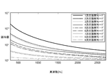
- FIG. 3 is a graph showing the analysis result of the frequency characteristics of the eigenvalues of the speaker array 20 shown in FIG.
- the horizontal axis of this graph shows the frequency, and the vertical axis shows the eigenvalues.
- Numerical analysis of the nine speakers shown in FIG. 2 provided nine eigenvalues corresponding to the primary to ninth radiation modes. It can be seen that the eigenvalues in each radiation mode are different from each other. It can also be seen that the higher the frequency, the smaller the difference between the eigenvalues. From the results of the numerical analysis shown in FIG. 3, it can be seen that the eigenvalues corresponding to the primary radiation modes are larger than the eigenvalues corresponding to the other radiation modes at all frequencies. This means that among the primary to ninth radiation modes, the primary radiation mode is most suitable for localizing the sound field over a wide frequency range.
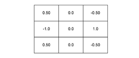
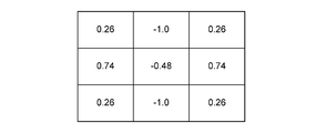
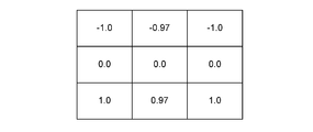
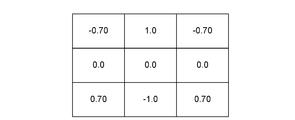
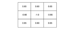
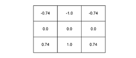
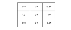
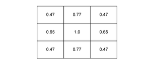
- 4 to 12 show the numerical analysis results of the eigenvectors in the 1st to 9th order radiation modes of the speaker array 20 shown in FIG. 2 at 300 Hz, respectively.
- 13 to 21 show the numerical analysis results of the eigenvectors in the 1st to 9th order radiation modes of the speaker array 20 shown in FIG. 2 at 2700 Hz, respectively.
- 4 to 21 show that the vector elements of the eigenvectors are arranged in 3 rows and 3 columns in the same manner as the speaker array 20, and which vector element is associated with which speaker.
- the vector elements in the first row and first column of the eigenvectors shown in FIGS. 4 to 21 indicate the vibration velocity of the speaker 20-1.
- the vector element in the first row and second column indicates the vibration velocity of the speaker 20-2.
- the vector element in the first row and third column indicates the vibration velocity of the speaker 20-3.
- the vector element in the second row and the first column indicates the vibration velocity of the speaker 20-4.
- the vector element in the second row and second column indicates the vibration velocity of the speaker 20-5.
- the vector element in the second row and third column indicates the vibration velocity of the speaker 20-6.
- the vector element in the third row and the first column indicates the vibration velocity of the speaker 20-7.
- the vector element in the third row and second column indicates the vibration velocity of the speaker 20-8.
- the vector element in the third row and third column indicates the vibration velocity of the speaker 20-9.
- the negative vibration velocity means that the vibration direction of the speaker (that is, the phase of the sound wave generated by the speaker) differs from the positive vibration velocity by 180 °
- Each vector element of the eigenvectors shown in FIGS. 4 to 21 is normalized by the vector element having the maximum value. Since the specific acoustic impedance depends on the frequency, the eigenvalues and the eigenvectors also depend on the frequency. However, as shown in FIGS. 4 to 21, it can be seen that the frequency dependence of the eigenvectors in the same radiation mode is low. This is because the eigenvectors at a certain frequency (eg 300Hz) in a certain radiation mode are locally in the sound field at a practically sufficient level in a certain frequency range (eg 300-2700Hz) including that frequency (eg 300Hz). It shows that it can be used for conversion. Here, since the frequency range of 300 to 2700 Hz is a band used for voice calls, it is suitable for localization of the sound field.
- a certain frequency eg 300Hz
- 300-2700Hz a certain frequency range
- the frequency range of 300 to 2700 Hz is a band used for voice calls, it is suitable for
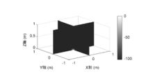
- FIG. 22 is a graph of the sound pressure distribution (sound pressure distribution in the XZ plane and the YZ plane in the XYZ space) at 1000 Hz when the speaker array 20 shown in FIG. 2 is driven based on the eigenvector of the first-order radiation mode. Shown.
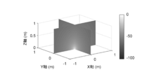
- FIG. 23 shows the sound pressure distribution at 1000 Hz (XZ plane in XYZ space) when all nine speakers 20-1, 20-2, ..., 20-9 are driven with the same phase and the same amplitude.
- the graph of the sound pressure distribution in the YZ plane The sound pressure level can be described as in Eq. (21).
- SPL indicates the sound pressure level [dB]
- p (y) indicates the complex sound pressure at a predetermined point (measurement point) determined by the coordinates (x, y, z), and p (y 0 ).
- p (y 0 ) Indicates the complex sound pressure at the center of the speaker array 20 shown in FIG. 2 (that is, the origin (0, 0, 0) in the XYZ space).
- FIG. 24 is a schematic view of the speaker array 20 actually manufactured by the applicant.
- the speaker array 20 includes nine speakers arranged in three rows and three columns on an XY plane (two-dimensional plane) in the XYZ space, and the shape of each speaker is circular.
- the speaker indicated by reference numeral 20-5 is referred to as a center speaker.
- the speakers indicated by reference numerals 20-2 and 20-8 are referred to as first reverse phase speakers.
- the speakers indicated by reference numerals 20-4 and 20-6 are referred to as second reverse phase speakers.
- the speakers indicated by reference numerals 20-1, 20-3, 20-7, 20-9 are referred to as edge speakers.
- the distance between the centers of the two adjacent speakers in the X direction is 0.05 m
- the distance between the centers of the two adjacent speakers in the Y direction is 0.04 m.
- the center of the speaker array 20 shown in FIG. 24 is set as the origin (0,0,0) in the XYZ space, and the speaker array 20 of FIG. 24 is set based on the eigenvector of the first-order radiation mode at 300 Hz (the eigenvector shown in FIG. 4).
- the sound pressure was measured at a point (0, 0, z) separated from the origin by a distance z in the Z direction.
- the sound pressure was measured twice.
- the input of the drive signal to the center speaker 20-5 was delayed by a certain time (0.0005 seconds) from the input of the drive signal to the other speakers.
- the drive signals input to all the speakers were set so as not to cause a time difference.
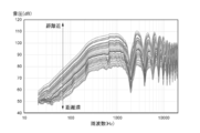
- FIG. 25 shows a graph of the distance attenuation sound pressure frequency characteristic in the first measurement.
- FIG. 26 shows a graph of the distance attenuation sound pressure frequency characteristic in the second measurement.
- the horizontal axis represents frequency [Hz] and the vertical axis represents sound pressure [dB].
- “near distance” in FIGS. 25 and 26 shows a graph of the distance attenuation sound pressure frequency characteristic having a small z value
- "far distance” shows a graph of the distance attenuation sound pressure frequency characteristic having a large z value. Shown.
- the decrease in sound pressure in the frequency range of about 300 to 1000 Hz becomes an inverse square characteristic. It was almost the same, and the decrease in sound pressure in the frequency range of 2000 to 3000 Hz was found to exceed the inverse square characteristic.
- the second measurement since the drive signals input to all the speakers were set so as not to cause a time difference, a decrease exceeding the inverse square characteristic was observed in the frequency range of about 300 to 3000 Hz. From these measurement results, it can be seen that the sound pressure can be reduced beyond the inverse square characteristic by setting the drive signals input to all the speakers so that there is no time difference.
- the deviation of the phase difference of the sound waves generated by the two speakers driven so that the phase difference determined from the eigenvector is 180 ° from 180 ° is the deviation of the speaker array 20 on the normal line (Z axis) of the XY plane.
- the point (0,0, z) is a point in the XYZ space where it is expected that sufficient attenuation of the sound pressure can be obtained in order to realize a personal acoustic space.
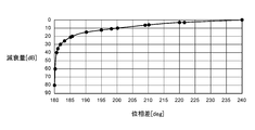
- FIG. 27 is a graph showing the relationship between the phase difference between two sound waves having the same amplitude and the amount of attenuation of the combined wave of the two sound waves.
- the horizontal axis of FIG. 27 shows the phase difference of the other of the two sound waves with reference to one, and the vertical axis shows the amount of attenuation. From this graph, when the phase difference between the two sound waves is within 240 °, that is, when the deviation of the phase difference between the two sound waves from 180 ° is within ⁇ 60 °, the attenuation of the composite wave can be obtained. You can see that. In order to realize a decrease in sound pressure at a practically sufficient level, it is desirable to obtain an attenuation of about 30 dB.
- the phase difference between the two sound waves having substantially the same amplitude is within about 182 °, that is, the phase difference between the two sound waves having substantially the same amplitude. It is desirable that the deviation from 180 ° is within about ⁇ 2 °.
- the two sound waves having substantially the same amplitude mean two sound waves having a relationship in which the ratio of the amplitude of the other sound wave to the amplitude of one of the two sound waves is 0.97 or more.
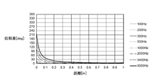
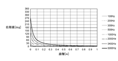
- the applicant changes the relative distance of the point (0, 0, z) to the center speaker 20-5 and the frequency of the sound wave, and changes the point (0, 0, z) as shown in FIGS. 28 to 30.
- the phase difference of the sound wave was calculated by 0, z).
- the horizontal axis of FIG. 28 indicates the distance between the center speaker 20-5 and the point (0, 0, z).
- the vertical axis of FIG. 28 is at the point of sound wave (0,0, z) from the first reverse phase speaker 20-2 with respect to the phase at the point of sound wave (0,0, z) from the center speaker 20-5. It shows the phase difference.
- the horizontal axis of FIG. 29 shows the distance between the center speaker 20-5 and the point (0, 0, z).
- the vertical axis of FIG. 29 is at the point of sound wave (0,0, z) from the second reverse phase speaker 20-4 with respect to the phase at the point of sound wave (0,0, z) from the center speaker 20-5. It shows the phase difference.
- the horizontal axis of FIG. 30 indicates the distance between the center speaker 20-5 and the point (0, 0, z).
- the vertical axis of FIG. 30 is the phase difference at the point (0,0, z) of the sound wave from the edge speaker 20-1 with respect to the phase at the point (0,0, z) of the sound wave from the center speaker 20-5. Is shown.
- the measurement is the same as that shown in FIGS. 28 to 30.
- the phase difference of the sound wave measured at the point (0, 0, z) at a distance of about 0.1 to 1 m from the center speaker 20-5 is 300 Hz, 1000 Hz, 2000 Hz, and 3400 Hz. At frequencies of 54 °, 180 °, 360 °, and 252 °, respectively.
- the amplitude of the composite wave measured at (0, 0, z) tended to decrease, and the amplitude of the composite wave measured at the point (0, 0, z) tended to increase near 3400 Hz.
- the upper limit of the frequency of the sound wave is preferably about 2000 Hz.
- the deviation of the phase difference of sound waves having substantially the same amplitude from 180 ° caused by two speakers driven so that the phase difference determined from the eigenvector is 180 ° is on the normal (Z axis) of the XY plane.
- the distance between the point (0,0, z) and each speaker so as to be limited within ⁇ 2 °. It is desirable to set the upper limit of the frequency range of the sound wave and the allowable delay time of the drive signal of each speaker. In particular, it is desirable to set the allowable delay time of the drive signal of each speaker to substantially zero.
- FIG. 31 is a flowchart showing a processing flow of the acoustic output method according to the embodiment of the present invention.
- a speaker array 20 including a plurality of speakers 20-1, 20-2, 20-3, ..., 20-N arranged in a two-dimensional plane is prepared.
- the amplitude and phase of the drive signal of each speaker of the amplifier array 30 including the plurality of amplifiers 30-1, 30-2, ..., 30-N are controlled according to the eigenvectors of the predetermined radiation mode of the speaker array 20. To do.
- the eigenvectors at a certain frequency (eg 300Hz) in a certain radiation mode are in a certain frequency range (eg 300-2700Hz) including that frequency (eg 300Hz).
- a certain frequency range eg 300-2700Hz
- that frequency eg 300Hz
Landscapes
- Health & Medical Sciences (AREA)
- Otolaryngology (AREA)
- Engineering & Computer Science (AREA)
- Physics & Mathematics (AREA)
- Acoustics & Sound (AREA)
- Signal Processing (AREA)
- General Health & Medical Sciences (AREA)
- Multimedia (AREA)
- Circuit For Audible Band Transducer (AREA)
- Obtaining Desirable Characteristics In Audible-Bandwidth Transducers (AREA)
Abstract
よりコンパクトな形状でスピーカアレイの駆動を制御することにより、音場の局所化を実現するのに十分な距離減衰を得る音響出力装置を提案する。 音響出力装置10は、2次元平面に配列されている複数のスピーカ20-1,20-2,…,20-Nを備えるスピーカアレイ20と、複数のアンプ40-1,40-2,…,40-Nを備えるアンプアレイ40であって、スピーカアレイ20の所定の放射モードの固有ベクトルに従って、各スピーカの駆動信号の振幅及び位相を制御する、アンプアレイ40とを備える。
Description
本発明は、音響出力装置及び音響出力方法に関わる。
特定のユーザにだけ音が届き、その周囲の人々に音が届かなければ、その特定のユーザだけのパーソナルな音響空間を実現できる。 各ユーザがパーソナルな音響空間を有していれば、お互いが近くに居ても、互いに干渉することなく、別々の音(例えば、音楽や音声通話など)を同時に聞くことができる。音場の局所化の実現を考えるとき、音の伝搬方向の制御と、音が届く距離範囲の制御という二つの側面を検討する必要がある。音の伝搬方向の制御とは、所定の方向にだけ音を届けることを意味する。例えば、指向性の高いスピーカを用いることにより、音の伝搬方向を制御する手法が知られている。音が届く距離範囲の制御とは、予め定められた距離範囲内に限り音を届けることを意味する。通常のスピーカから放射される音の距離減衰は、音の伝搬距離が2倍になる毎に音圧レベルが6dB下がる逆二乗特性を有しており、音場の局所化を実現するには、逆二乗特性を上回る距離減衰が必要である。このような事情を背景に、非特許文献1は、音場の局所化を実現するのに十分な距離減衰を得る手法について言及している。この手法は、多面体形状のスピーカアレイの放射モードの固有ベクトルを計算し、計算された固有ベクトルに従って、各スピーカの振幅及び位相を制御するものである。
A.M. Pasqual,"Analysis of the complex sound power in the near field of spherical loudspeaker arrays," Journal of Sound and Vibration, 456 (2019) 331-352
しかし、スピーカアレイの形状を、非特許文献1に記載されているような多面体形状にすると、スピーカアレイのサイズが大型化してしまうため、パーソナルな音響空間の実現には不向きである。
そこで、本発明は、よりコンパクトな形状で音場の局所化を実現するのに十分な距離減衰を得る音響出力装置及び音響出力方法を提案することを課題とする。
上述の課題を解決するため、本発明に関わる音響出力装置は、2次元平面に配列されている複数のスピーカを備えるスピーカアレイと、複数のアンプを備えるアンプアレイであって、スピーカアレイの所定の放射モードの固有ベクトルに従って、各スピーカの駆動信号の振幅及び位相を制御する、アンプアレイと、を備える。スピーカアレイの形状を2次元平面とすることにより、スピーカアレイのサイズを小型化できるため、パーソナルな音響空間の実現に好適である。
スピーカアレイの駆動制御に用いられる固有ベクトルは、例えば、所定の放射モードのある周波数における固有ベクトルである。アンプアレイは、ある周波数を含む一定の周波数範囲において、各スピーカの駆動信号の振幅及び位相を制御してもよい。同一の放射モードにおける固有ベクトルの周波数依存性は低いため、ある放射モードのある周波数における固有ベクトルは、その周波数を含む一定の周波数範囲において、実用上十分なレベルで音場の局所化に用いることができる。これにより、周波数毎に異なる固有ベクトルに従って各スピーカの振幅及び位相を制御する必要がなく、スピーカアレイの駆動制御を簡素化できる。
固有ベクトルから定まる位相差が180°になるように実質的に同一の振幅で駆動される二つのスピーカにより生じる音波の位相差の180°からのずれは、2次元平面の法線上におけるスピーカアレイの中心から所定の距離にあるポイントにおいて、所定の角度範囲(例えば、±2°)内に制限されるように、ポイントと各スピーカとの間の距離、周波数範囲の上限値、及び駆動信号の許容遅延時間を予め設定してもよい。特に、各スピーカの駆動信号の許容遅延時間は、実質的にゼロとするのが望ましい。これにより、音場の局所化を実現するのに十分な距離減衰を得ることができる。
ここで、所定の放射モードは、例えば、閾値以上の固有値に対応する放射モードが好ましい。この閾値は、複数の放射モードのうち、相対的に低い固有値に対応する放射モードと、相対的に高い固有値に対応する放射モードとを区別する値である。閾値以上の固有値に対応する放射モードでスピーカアレイを駆動することにより、アクティブ音響パワーに対するリアクティブ音響パワーの比率を高めることができ、音場の局所化に適している。
本発明に関わる音響出力方法は、2次元平面に配列されている複数のスピーカを備えるスピーカアレイを準備するステップと、複数のアンプを備えるアンプアレイの各スピーカの駆動信号の振幅及び位相を、スピーカアレイの所定の放射モードの固有ベクトルに従って、制御するステップと、を含む。スピーカアレイの形状を2次元平面とすることにより、スピーカアレイのサイズを小型化できるため、パーソナルな音響空間の実現に好適である。
本発明によれば、スピーカアレイの形状を2次元平面とすることにより、スピーカアレイのサイズを小型化できるため、パーソナルな音響空間の実現に好適である。
以下、図面を参照しながら本発明の実施形態について説明する。ここで、同一符号は同一の構成要素を示すものとし、重複する説明は省略する。
図1は本発明の実施形態に関わる音響出力装置10の構成を示す説明図である。音響出力装置10は、スピーカアレイ20と、アンプアレイ30とを備えている。スピーカアレイ20は、2次元平面に配列されているN個のスピーカ20-1,20-2,20-3,…,20-Nを備えている。ここで、Nは2以上の整数である。スピーカアレイ20を駆動する事前準備として、スピーカアレイ20の所定の放射モードの固有ベクトルは、計算済みであるものとする。固有ベクトルは、N個のスピーカ20-1,20-2,20-3,…,20-Nのそれぞれの振動速度に対応するN個のベクトル要素を有する。例えば、固有ベクトルのN個のベクトル要素のうちi番目のベクトル要素は、スピーカアレイ20のうちi番目のスピーカ20-iの振動速度を示す。ここで、iは1以上N以下の整数である。アンプアレイ30は、N個のアンプ30-1,30-2,30-3,…,30-Nを備えている。アンプアレイ30のうちi番目のアンプ30-iは、固有ベクトルのN個のベクトル要素のうちi番目のベクトル要素に従って、スピーカアレイ20のうちi番目のスピーカ20-iの駆動信号の振幅及び位相を制御する。
スピーカアレイ20により生成される音(複素音響パワー)は、比較的遠方まで届く成分(空間中を伝搬するエネルギー成分)と、比較的近くに留まる成分(ニアフィールドのエネルギー成分)とを含む。空間中を伝搬するエネルギー成分は、複素音響パワーの実部に相当し、このエネルギー成分は、アクティブ音響パワーと呼ばれる。一方、ニアフィールドのエネルギー成分は、複素音響パワーの虚部に相当し、このエネルギー成分は、リアクティブ音響パワーと呼ばれる。固有値の大きい放射モードほど、アクティブ音響パワーに対するリアクティブ音響パワーの比率を高めることができ、音場の局所化に適している。複数の放射モードのうち、固有値の高い放射モードの固有ベクトルを計算し、計算された固有ベクトルに従って、各スピーカの振幅及び位相を制御することにより、アクティブ音響パワーに対するリアクティブ音響パワーの比率を高めることができる。これにより、音場の局所化を実現することができる。
N個のスピーカ20-1,20-2,20-3,…,20-Nのそれぞれの複素音圧をベクトル要素とする複素音圧ベクトルをpとし、N個のスピーカ20-1,20-2,20-3,…,20-Nのそれぞれの振動速度(振動面の法線方向の複素速度)をベクトル要素とする振動ベクトルをvとし、比音響インピーダンスをZとすると、(1)式が成立する。音響の相反性により、Zは対称行列である。

複素音響パワーWは、(2)式のように記述できる。

ここで、sは、各スピーカの振動面の面積である。説明の便宜上、(2)式では、各スピーカの振動面の面積は、同一である場合を想定しているが、各スピーカの振動面の面積は必ずしも同一である必要はない。また、vHは、振動ベクトルvの共役転置行列である。
複素音響パワーWは、(3)式のように、実部と虚部とに分けることができる。

ここで、Wrは、アクティブ音響パワーを示し、Wiは、リアクティブ音響パワーを示す。
比音響インピーダンスZも、(4)式のように、実部と虚部とに分けることができる。

ここで、Zrは、音響レジスタンスを示し、Ziは、音響リアクタンスを示す。
上述の(1)式~(4)式から、以下の(5)式及び(6)式が得られる。


ここで、音響レジスタンスZr及び音響リアクタンスZiは、対角行列ではないため、各スピーカは、アクティブ音響パワーWr及びリアクティブ音響パワーWiに独立的には寄与しない。そこで、音響レジスタンスZr及び音響リアクタンスZiを対角化する実変換行列φを考える。実変換行列φによる対角化により、以下の(7)式及び(8)式が成立する。


ここで、Dr及びDiは、対角行列であり、φTは、φの転置行列である。(9)式のように、振動ベクトルvを定義することにより、複素音響パワーWを(10)式のように記述することができる。


ここで、ベクトルuの各ベクトル要素は、複素音響パワーWに独立的に寄与する。また、uHは、ベクトルuの共役転置行列である。実変換行列φは、音響レジスタンスZr及び音響リアクタンスZiについての一般化固有値問題を解くことにより得られる固有ベクトルを各列に並べた行列である。実数、対称、正定である音響レジスタンスZr及び実数、対称である音響リアクタンスZiについての一般化固有値問題は、(11)式のように記述することができる。

ここで、Λは、固有値を各対角要素に並べた対角行列である。一般化固有値問題を解くために、音響レジスタンスZrについての標準固有値問題を最初に解く。実数、正定である固有値の対角行列Λrと、実数である固有ベクトルの直交行列φrとは、(12)式を満たす。

ここで、φT
rは、φrの転置行列である。φrΛr
-1/2を用いることにより、音響リアクタンスZiを(13)式のように変換することができる。

ここで、-1/2は、対角要素の平方根の逆数を意味する。Zi’は、実数、対称である。次に、Zi’についての標準固有値問題を解く。実数である固有値を各対角要素に並べた対角行列Λと、実数である固有ベクトルを各列に並べた直交行列φiとは、(14)式を満たす。

φを(15)式のように定義すると、(16)式及び(17)式に示すような対角化が可能になる。なお、φは実数行列である。



ここで、Iは、単位行列である。(16)式の両辺に右側からΛを乗じ、その結果を(17)式と比較すると、(11)式が得られる。ここで、Λは、固有値を各対角要素に並べた対角行列であり、φは、固有ベクトルを各列に並べた行列である。(16)式及び(17)式に示す対角化により、複素音響パワーWは、(18)式のように記述できる。

ベクトルuは、各一般化放射モードの複素振幅を示す。(18)式から、各放射モードは、複素音響パワーに独立的に寄与することが分かる。
m次の放射モードのみが励起される場合、(9)式及び(18)式は、それぞれ、(19)式及び(20)式のように記述できる。


ここで、λmは、m次の固有値であり、φmは、m次の固有ベクトルであり、umは、m次の放射モードの複素振幅である。φmは、スピーカアレイ20のm次の放射モードにおける各スピーカの振動速度分布を示す。なお、本明細書では、複数の固有値のうちm番目に高い固有値に対応する放射モードをm次の放射モードと呼ぶ。ここで、mは正数である。
例えば、N=2の場合、固有ベクトルφm=[φ1m φ2m]tと記述できる。φ1mは、m次の放射モードにおけるスピーカ20-1の振動速度を示し、φ2mは、m次の放射モードにおけるスピーカ20-2の振動速度を示す。放射モードは、各スピーカが互いに連成せずに複素音響パワーに寄与する振動速度分布を意味する。
(20)式から理解できるように、固有値λmは、m次の放射モードにおけるアクティブ音響パワーWrに対するリアクティブ音響パワーWiの比率(Wr/Wi)を示す。固有値λmの大きい放射モードほど、音場の局所化に適している。
例えば、N=2の場合、[v1 v2]t=[φ1m φ2m]tumという速度分布でスピーカ20-1,20-2を駆動することにより、音場の局所化を実現できる。ここで、例えば、um=(1/λm)1/2と設定すると、リアクティブ音響パワーWiを一定に保つことができる。
N個のアンプ30-1,30-2,30-3,…,30-Nのそれぞれに信号umが入力される。アンプアレイ30のうちi番目のアンプ30-iは、固有ベクトルのN個のベクトル要素のうちi番目のベクトル要素に信号umを乗じて得られる駆動信号を用いて、スピーカアレイ20のうちi番目のスピーカ20-iの振幅及び位相を制御する。
例えば、N=2の場合、アンプ30-1,30-2のそれぞれに信号umが入力される。アンプ30-1は、信号umにφ1mを乗じて得られる駆動信号を用いて、スピーカ20-1を駆動する。即ち、アンプ30-1は、φ1mの大きさ(絶対値)に基づいて、スピーカ20-1を駆動する駆動信号の振幅を調整し、φ1mの符号(正又は負)に基づいて、スピーカ20-1を駆動する駆動信号の位相(極性)を調整する。同様に、アンプ30-2は、信号umにφ2mを乗じて得られる駆動信号を用いて、スピーカ20-2を駆動する。即ち、アンプ30-2は、φ2mの大きさ(絶対値)に基づいて、スピーカ20-2を駆動する駆動信号の振幅を調整し、φ2mの符号(正又は負)に基づいて、スピーカ20-2を駆動する駆動信号の位相(極性)を調整する。なお、固有値も固有個ベクトルも実数であるため、スピーカ20-1,20-2の駆動信号の位相の調整は、正又は負のうち何れか一方の符号を設定するだけでよい。
なお、上述の説明では、アンプの数とスピーカの数とが同一である場合を例示したが、アンプの数とスピーカの数は必ずしも同一である必要はない。例えば、ある放射モードにおいて、N個のスピーカのうちk個のスピーカを同一の振幅及び位相で駆動させる場合には、一つのアンプでk個のスピーカの振幅及び位相を同時に制御してもよい。この場合、アンプの数をスピーカの数よりも少なくできる。但し、kは1以上N以下の整数である。
図2は本発明の実施形態に関わるスピーカアレイ20の一例を示す説明図である。図2に示すスピーカアレイ20は、固有値及び固有ベクトルの数値解析を行うためのシミュレーションモデルであり、この例では、スピーカアレイ20は、XYZ空間内のXY平面(無限大バッフル)上に3行3列に配置される9個のスピーカ20-1,20-2,…,20-9を備えている。各スピーカは一辺の長さがlpの正方形である。X方向における各スピーカの間隔はlxであり、Y方向における各スピーカの間隔はlyである。数値解析のシミュレーションでは、lp=0.01m、lx=0.03m、及びly=0.02mとした。また、固有値及び固有ベクトルの数値解析では、無限大バッフル上に配置されたスピーカアレイ20から自由空間へ音が放射されるものと仮定した。
図3は図2に示すスピーカアレイ20の固有値の周波数特性の解析結果を示すグラフである。このグラフの横軸は周波数を示し、縦軸は固有値を示す。図2に示す9個のスピーカの数値解析により、1次から9次の放射モードに対応する9個の固有値が得られた。各放射モードにおける固有値は、互いに異なることが分かる。また、周波数が高くなる程、固有値同士の差は小さくなることが分かる。図3に示す数値解析の結果から、1次の放射モードに対応する固有値が全周波数において他の放射モードに対応する固有値よりも大きい値を示すことが分かる。これは、1次から9次の放射モードの中で、1次の放射モードが、広い周波数範囲にわたって、音場の局所化に最も適していることを意味する。
図4~図12は、それぞれ、図2に示すスピーカアレイ20の300Hzにおける1次~9次の放射モードにおける固有ベクトルの数値解析結果を示す。図13~図21は、それぞれ、図2に示すスピーカアレイ20の2700Hzにおける1次~9次の放射モードにおける固有ベクトルの数値解析結果を示す。図4~図21は、固有ベクトルのベクトル要素をスピーカアレイ20と同様に3行3列に配列し、どのベクトル要素がどのスピーカに対応付けられるのかを示している。
図4~図21に示す固有ベクトルの1行1列目のベクトル要素は、スピーカ20-1の振動速度を示す。1行2列目のベクトル要素は、スピーカ20-2の振動速度を示す。1行3列目のベクトル要素は、スピーカ20-3の振動速度を示す。2行1列目のベクトル要素は、スピーカ20-4の振動速度を示す。2行2列目のベクトル要素は、スピーカ20-5の振動速度を示す。2行3列目のベクトル要素は、スピーカ20-6の振動速度を示す。3行1列目のベクトル要素は、スピーカ20-7の振動速度を示す。3行2列目のベクトル要素は、スピーカ20-8の振動速度を示す。3行3列目のベクトル要素は、スピーカ20-9の振動速度を示す。なお、負の振動速度は、正の振動速度に対してスピーカの振動の方向(即ち、スピーカにより生じる音波の位相)が180°異なることを意味する。
図4~図21に示す固有ベクトルの各ベクトル要素は、最大の値をするベクトル要素によって正規化されている。比音響インピーダンスは、周波数に依存するため、固有値及び固有ベクトルも周波数に依存する。しかし、図4~図21に示すように、同一の放射モードにおける固有ベクトルの周波数依存性は低いことが分かる。これは、ある放射モードのある周波数(例えば、300Hz)における固有ベクトルは、その周波数(例えば、300Hz)を含む一定の周波数範囲(例えば、300~2700Hz)において、実用上十分なレベルで音場の局所化に用いることができることを示している。ここで、300~2700Hzの周波数範囲は、音声通話に用いられる帯域であるため、音場の局在化に好適である。
図22は、1次の放射モードの固有ベクトルに基づいて、図2に示すスピーカアレイ20を駆動したときの1000Hzにおける音圧分布(XYZ空間内のXZ平面及びYZ平面における音圧分布)のグラフを示す。一方、図23は、9個のスピーカ20-1,20-2,…,20-9の全てを同一の位相で同一の振幅により駆動したときの1000Hzにおける音圧分布(XYZ空間内のXZ平面及びYZ平面における音圧分布)のグラフを示す。音圧レベルは、(21)式のように記述できる。

ここで、SPLは、音圧レベル[dB]を示し、p(y)は、座標(x,y,z)により定まる所定のポイント(測定点)における複素音圧を示し、p(y0)は、図2に示すスピーカアレイ20の中心(即ち、XYZ空間の原点(0,0,0))における複素音圧を示す。
図22及び図23のグラフを比較すると、1次の放射モードの固有ベクトルに基づいて、スピーカアレイ20を駆動することにより、音場の局所化を実現できていることが分かる。
図24は、本出願人が実際に作製したスピーカアレイ20の模式図である。このスピーカアレイ20は、XYZ空間内のXY平面(2次元平面)上に3行3列に配列される9個のスピーカを備えており、各スピーカの形状は、円形である。符号20-5が示すスピーカをセンター・スピーカと呼ぶ。符号20-2,20-8が示すスピーカを第1の逆相スピーカと呼ぶ。符号20-4,20-6が示すスピーカを第2の逆相スピーカと呼ぶ。符号20-1,20-3,20-7,20-9が示すスピーカをエッジ・スピーカと呼ぶ。隣り合う二つのスピーカのX方向の中心間距離は、0.05mであり、隣り合う二つのスピーカのY方向の中心間距離は、0.04mである。
図24に示すスピーカアレイ20の中心をXYZ空間の原点(0,0,0)とし、300Hzにおける1次の放射モードの固有ベクトル(図4に示す固有ベクトル)に基づいて、図24のスピーカアレイ20を駆動することにより、原点からZ方向に距離zだけ離れているポイント(0,0,z)で音圧の測定を行った。音圧の測定は2回行った。1回目の測定では、センター・スピーカ20-5への駆動信号の入力は、他のスピーカへの駆動信号の入力よりも一定時間(0.0005秒)遅れていた。2回目の測定では、全てのスピーカに入力される駆動信号に時間差が生じないように設定した。
図25は1回目の測定における距離減衰音圧周波数特性のグラフを示す。図26は2回目の測定における距離減衰音圧周波数特性のグラフを示す。図25及び図26において、横軸は周波数[Hz]を示し、縦軸は音圧[dB]を示す。また、図25及び図26の「距離近」は、zの値が小さい距離減衰音圧周波数特性のグラフを示し、「距離遠」は、zの値が大きい距離減衰音圧周波数特性のグラフを示している。
1回目の測定では、センター・スピーカ20-5と他のスピーカとの間で駆動信号の入力に時間差が生じているため、約300~1000Hzの周波数範囲において音圧の低下は、逆二乗特性にほぼ一致し、2000~3000Hzの周波数範囲において音圧の低下は、逆二乗特性を超える低下が見られた。一方、2回目の測定では、全てのスピーカに入力される駆動信号に時間差が生じないように設定されているため、約300~3000Hzの周波数範囲において逆二乗特性を超える低下が見られた。これらの測定結果から、全てのスピーカに入力される駆動信号に時間差が生じないように設定することで、逆二乗特性を超える音圧の低下を実現できることが分かる。
次に、固有ベクトルから定まる位相差が180°になるように駆動される二つのスピーカにより生じる音波の位相差の180°からのずれが、XY平面の法線(Z軸)上におけるスピーカアレイ20の中心から所定の距離にあるポイント(0,0,z)において、どの程度の範囲内にあれば、音圧の十分な減衰が得られるのかについて考察する。ここで、ポイント(0,0,z)は、パーソナルな音響空間を実現する上で、音圧の十分な減衰が得られることが期待されるXYZ空間内の点である。
図27は同一の振幅を有する二つ音波の位相差と、その二つの音波の合成波の減衰量との関係を示すグラフである。図27の横軸は二つの音波のうち一方を基準とする他方の位相差を示し、縦軸は減衰量を示す。このグラフから、二つ音波の位相差が240°以内である場合、即ち、二つ音波の位相差の180°からのずれが±60°以内である場合には、合成波の減衰が得られることが分かる。実用上十分なレベルで音圧の低下を実現するには、約30dB程度の減衰を得ることが望ましい。約30dB程度の減衰を得るには、実質的に同一の振幅を有する二つ音波の位相差は、約182°以内であること、即ち、実質的に同一の振幅を有する二つ音波の位相差の180°からのずれが約±2°以内であることが望ましい。なお、実質的に同一の振幅を有する二つの音波とは、二つの音波のうち一方の振幅に対する他方の振幅の比率が0.97以上である関係を有する二つの音波を意味する。
次に、本出願人は、センター・スピーカ20-5に対するポイント(0,0,z)の相対的な距離及び音波の周波数を変えながら、図28~図30に示すように、ポイント(0,0,z)で音波の位相差を計算した。
図28の横軸は、センター・スピーカ20-5とポイント(0,0,z)との間の距離を示している。図28の縦軸は、センター・スピーカ20-5からの音波のポイント(0,0,z)における位相に対する第1の逆相スピーカ20-2からの音波のポイント(0,0,z)における位相の差を示している。
図29の横軸は、センター・スピーカ20-5とポイント(0,0,z)との間の距離を示している。図29の縦軸は、センター・スピーカ20-5からの音波のポイント(0,0,z)における位相に対する第2の逆相スピーカ20-4からの音波のポイント(0,0,z)における位相の差を示している。
図30の横軸は、センター・スピーカ20-5とポイント(0,0,z)との間の距離を示している。図30の縦軸は、センター・スピーカ20-5からの音波のポイント(0,0,z)における位相に対するエッジ・スピーカ20-1からの音波のポイント(0,0,z)における位相の差を示している。
図28~図30の測定結果に示すように、センター・スピーカ20-5に対するポイント(0,0,z)の相対的な距離を変えると、ポイント(0,0,z)で測定される音波の位相差が変わることが分かる。また、ポイント(0,0,z)で測定される音波の位相差は、音波の周波数に依存して変化し、音波の周波数が高くなる程、位相差の変化も大きくなる。
なお、センター・スピーカ20-5への駆動信号の入力が、他のスピーカへの駆動信号の入力よりも一定時間(0.0005秒)遅れている場合、図28~図30に示す測定と同様の測定において、センター・スピーカ20-5からの距離が0.1~1m程度の距離にあるポイント(0,0,z)で測定される音波の位相差は、300Hz、1000Hz、2000Hz、及び3400Hzの周波数において、それぞれ、54°、180°、360°、及び252°であった。
また、センター・スピーカ20-5への駆動信号の入力が、他のスピーカへの駆動信号の入力よりも一定時間(0.0005秒)遅れている場合、300Hz付近では、ポイント(0,0,z)で測定される合成波の振幅に増減は見られず、1000Hz付近では、ポイント(0,0,z)で測定される合成波の振幅は増加傾向にあり、2000Hz付近では、ポイント(0,0,z)で測定される合成波の振幅は減少傾向にあり、3400Hz付近では、ポイント(0,0,z)で測定される合成波の振幅は増加傾向にあった。
上述の測定結果を踏まえると、XY平面の法線(Z軸)上でスピーカアレイ20の中心から所定の距離(例えば、0.05m)にあるポイント(0,0,z)で測定される音波の位相差の180°からのずれを±60°以内に制限するには、音波の周波数の上限値は、約2000Hz程度が望ましい。固有ベクトルから定まる位相差が180°になるように駆動される二つのスピーカにより生じる実質的に同一の振幅を有する音波の位相差の180°からのずれは、XY平面の法線(Z軸)上におけるスピーカアレイ20の中心から所定の距離にあるポイント(0,0,z)において、±2°以内に制限されるように、ポイント(0,0,z)と各スピーカとの間の距離、音波の周波数範囲の上限値、及び各スピーカの駆動信号の許容遅延時間を設定するのが望ましい。特に、各スピーカの駆動信号の許容遅延時間は、実質的にゼロに設定するのが望ましい。
図31は本発明の実施形態に関わる音響出力方法の処理の流れを示すフローチャートである。
ステップ311において、2次元平面に配列されている複数のスピーカ20-1,20-2,20-3,…,20-Nを備えるスピーカアレイ20を準備する。
ステップ312において、複数のアンプ30-1,30-2,…,30-Nを備えるアンプアレイ30の各スピーカの駆動信号の振幅及び位相を、スピーカアレイ20の所定の放射モードの固有ベクトルに従って、制御する。
ステップ311において、2次元平面に配列されている複数のスピーカ20-1,20-2,20-3,…,20-Nを備えるスピーカアレイ20を準備する。
ステップ312において、複数のアンプ30-1,30-2,…,30-Nを備えるアンプアレイ30の各スピーカの駆動信号の振幅及び位相を、スピーカアレイ20の所定の放射モードの固有ベクトルに従って、制御する。
同一の放射モードにおける固有ベクトルの周波数依存性は低いため、ある放射モードのある周波数(例えば、300Hz)における固有ベクトルは、その周波数(例えば、300Hz)を含む一定の周波数範囲(例えば、300~2700Hz)において、実用上十分なレベルで音場の局所化に用いることができる。これにより、周波数毎に異なる固有ベクトルに従って各スピーカの振幅及び位相を制御する必要がなく、スピーカアレイ30の駆動制御を簡素化できる。
以上、説明した実施形態は、本発明の理解を容易にするためのものであり、本発明を限定して解釈するためのものではない。本発明は、その趣旨を逸脱することなく、変更又は改良され得るととともに、本発明にはその等価物も含まれる。すなわち、実施形態に当業者が適宜設計変更を加えたものも、本発明の特徴を備えている限り、本発明の範囲に包含される。また、実施形態が備える各要素は、技術的に可能な限りにおいて組み合わせることができ、これらを組み合わせたものも、本発明の特徴を含む限り、本発明の範囲に包含される。
10…音響出力装置
20…スピーカアレイ
20-1,20-2,…,20-N…スピーカ
30…信号処理回路
40…アンプアレイ
40-1,40-2,…,40-N…アンプ
20…スピーカアレイ
20-1,20-2,…,20-N…スピーカ
30…信号処理回路
40…アンプアレイ
40-1,40-2,…,40-N…アンプ
Claims (7)
- 2次元平面に配列されている複数のスピーカを備えるスピーカアレイと、
複数のアンプを備えるアンプアレイであって、前記スピーカアレイの所定の放射モードの固有ベクトルに従って、各スピーカの駆動信号の振幅及び位相を制御する、アンプアレイと、
を備える音響出力装置。 - 請求項1に記載の音響出力装置であって、
前記固有ベクトルは、前記所定の放射モードのある周波数における固有ベクトルであり、
前記アンプアレイは、前記ある周波数を含む一定の周波数範囲において、各スピーカの駆動信号の振幅及び位相を制御する、音響出力装置。 - 請求項1又は2に記載の音響出力装置であって、
前記固有ベクトルから定まる位相差が180°になるように実質的に同一の振幅で駆動される二つのスピーカにより生じる音波の位相差の180°からのずれは、前記2次元平面の法線上における前記スピーカアレイの中心から所定の距離にあるポイントにおいて、所定の角度範囲内に制限されるように、前記ポイントと各スピーカとの間の距離、前記周波数範囲の上限値、及び前記駆動信号の許容遅延時間が予め定められている、音響出力装置。 - 請求項3に記載の音響出力装置であって、
前記所定の角度範囲は、±2°である、音響出力装置。 - 請求項3又は4に記載の音響出力装置であって、
前記駆動信号の許容遅延時間は、実質的にゼロである、音響出力装置。 - 請求項1乃至5のうち何れか1項に記載の音響出力装置であって、
前記所定の放射モードは、閾値以上の固有値に対応する放射モードである、音響出力装置。 - 2次元平面に配列されている複数のスピーカを備えるスピーカアレイを準備するステップと、
複数のアンプを備えるアンプアレイの各スピーカの駆動信号の振幅及び位相を、前記スピーカアレイの所定の放射モードの固有ベクトルに従って、制御するステップと、
を含む音響出力方法。
Priority Applications (2)
| Application Number | Priority Date | Filing Date | Title |
|---|---|---|---|
| JP2021545637A JP7373810B2 (ja) | 2019-09-12 | 2020-09-11 | 音響出力装置及び音響出力方法 |
| US17/642,538 US11955938B2 (en) | 2019-09-12 | 2020-09-11 | Acoustic output device and acoustic output method |
Applications Claiming Priority (2)
| Application Number | Priority Date | Filing Date | Title |
|---|---|---|---|
| US201962899229P | 2019-09-12 | 2019-09-12 | |
| US62/899,229 | 2019-09-12 |
Publications (1)
| Publication Number | Publication Date |
|---|---|
| WO2021049652A1 true WO2021049652A1 (ja) | 2021-03-18 |
Family
ID=74865748
Family Applications (1)
| Application Number | Title | Priority Date | Filing Date |
|---|---|---|---|
| PCT/JP2020/034592 Ceased WO2021049652A1 (ja) | 2019-09-12 | 2020-09-11 | 音響出力装置及び音響出力方法 |
Country Status (3)
| Country | Link |
|---|---|
| US (1) | US11955938B2 (ja) |
| JP (1) | JP7373810B2 (ja) |
| WO (1) | WO2021049652A1 (ja) |
Citations (1)
| Publication number | Priority date | Publication date | Assignee | Title |
|---|---|---|---|---|
| JP2015037207A (ja) * | 2013-08-12 | 2015-02-23 | 日本電信電話株式会社 | 音場収音再生装置、方法及びプログラム |
Family Cites Families (5)
| Publication number | Priority date | Publication date | Assignee | Title |
|---|---|---|---|---|
| CN100530350C (zh) | 2005-09-30 | 2009-08-19 | 中国科学院声学研究所 | 一种面向目标的声辐射生成方法 |
| EP3457719B1 (en) * | 2016-06-03 | 2020-11-25 | Huawei Technologies Co., Ltd. | Ultrasonic wave-based voice signal transmission system and method |
| US10080088B1 (en) * | 2016-11-10 | 2018-09-18 | Amazon Technologies, Inc. | Sound zone reproduction system |
| WO2019197002A1 (en) * | 2018-04-13 | 2019-10-17 | Aalborg Universitet | Generating sound zones using variable span filters |
| US11166090B2 (en) * | 2018-07-06 | 2021-11-02 | Eric Jay Alexander | Loudspeaker design |
-
2020
- 2020-09-11 WO PCT/JP2020/034592 patent/WO2021049652A1/ja not_active Ceased
- 2020-09-11 JP JP2021545637A patent/JP7373810B2/ja active Active
- 2020-09-11 US US17/642,538 patent/US11955938B2/en active Active
Patent Citations (1)
| Publication number | Priority date | Publication date | Assignee | Title |
|---|---|---|---|---|
| JP2015037207A (ja) * | 2013-08-12 | 2015-02-23 | 日本電信電話株式会社 | 音場収音再生装置、方法及びプログラム |
Non-Patent Citations (2)
| Title |
|---|
| PASQUAL, A. M. ET AL.: "Analysis of the complex sound power in the near field of spherical loudspeaker arrays", JOURNAL OF SOUND AND VIBRATION, vol. 456, 23 May 2019 (2019-05-23), pages 331 - 352, XP055805601 * |
| WEN, Y. ET AL.: "Target-Oriented Acoustic Radiation Generation Technique for Sound Field control", IEICE TRANSACTIONS ON FUNDAMENTALS OF ELECTRONICS, COMMUNICATIONS AND COMPUTER SCIENCES, vol. E89-A, no. 12, December 2006 (2006-12-01), pages 3671 - 3677, XP001505340, DOI: 10.1093/ietfec/e89-a.12.3671 * |
Also Published As
| Publication number | Publication date |
|---|---|
| JPWO2021049652A1 (ja) | 2021-03-18 |
| US20220329224A1 (en) | 2022-10-13 |
| JP7373810B2 (ja) | 2023-11-06 |
| US11955938B2 (en) | 2024-04-09 |
Similar Documents
| Publication | Publication Date | Title |
|---|---|---|
| Coleman et al. | Personal audio with a planar bright zone | |
| Coleman et al. | Acoustic contrast, planarity and robustness of sound zone methods using a circular loudspeaker array | |
| Simón Gálvez et al. | A superdirective array of phase shift sources | |
| US9319794B2 (en) | Surround sound system | |
| JP4987358B2 (ja) | マイクロフォンのモデリング | |
| US9392390B2 (en) | Method of applying a combined or hybrid sound-field control strategy | |
| Yang et al. | Acoustic beamforming of a parametric speaker comprising ultrasonic transducers | |
| Gálvez et al. | Personal audio loudspeaker array as a complementary TV sound system for the hard of hearing | |
| US8831248B2 (en) | Apparatus with directivity pattern | |
| KR20120077763A (ko) | 공간 음향에너지 분포 제어장치 및 방법 | |
| Ryan et al. | Near-field beamforming for microphone arrays | |
| Boone et al. | Design of a highly directional endfire loudspeaker array | |
| Yan et al. | Time-domain implementation of broadband beamformer in spherical harmonics domain | |
| Zhu et al. | Robust personal audio geometry optimization in the SVD-based modal domain | |
| US20100329480A1 (en) | Highly directive endfire loudspeaker array | |
| Huang et al. | Acoustic contrast control with a sound intensity constraint for personal sound systems | |
| CN114023307B (zh) | 声音信号处理方法、语音识别方法、电子设备和存储介质 | |
| Mabande et al. | Towards superdirective beamforming with loudspeaker arrays | |
| JP7373810B2 (ja) | 音響出力装置及び音響出力方法 | |
| CN100530350C (zh) | 一种面向目标的声辐射生成方法 | |
| Nakagawa et al. | Beam steering of portable parametric array loudspeaker | |
| CN103916733B (zh) | 基于均方误差最小准则的声能量对比控制方法及系统 | |
| Betlehem et al. | A directional loudspeaker array for surround sound in reverberant rooms | |
| CN108476371A (zh) | 声波场生成 | |
| EP3677049B1 (en) | Acoustic radiation control method and system |
Legal Events
| Date | Code | Title | Description |
|---|---|---|---|
| 121 | Ep: the epo has been informed by wipo that ep was designated in this application |
Ref document number: 20863197 Country of ref document: EP Kind code of ref document: A1 |
|
| ENP | Entry into the national phase |
Ref document number: 2021545637 Country of ref document: JP Kind code of ref document: A |
|
| NENP | Non-entry into the national phase |
Ref country code: DE |
|
| 122 | Ep: pct application non-entry in european phase |
Ref document number: 20863197 Country of ref document: EP Kind code of ref document: A1 |