WO2021045134A1 - Movable shaft and medical device comprising movable shaft - Google Patents
Movable shaft and medical device comprising movable shaft Download PDFInfo
- Publication number
- WO2021045134A1 WO2021045134A1 PCT/JP2020/033352 JP2020033352W WO2021045134A1 WO 2021045134 A1 WO2021045134 A1 WO 2021045134A1 JP 2020033352 W JP2020033352 W JP 2020033352W WO 2021045134 A1 WO2021045134 A1 WO 2021045134A1
- Authority
- WO
- WIPO (PCT)
- Prior art keywords
- pipe member
- width
- peripheral surface
- hole
- longitudinal direction
- Prior art date
Links
Images


Classifications
-
- A—HUMAN NECESSITIES
- A61—MEDICAL OR VETERINARY SCIENCE; HYGIENE
- A61M—DEVICES FOR INTRODUCING MEDIA INTO, OR ONTO, THE BODY; DEVICES FOR TRANSDUCING BODY MEDIA OR FOR TAKING MEDIA FROM THE BODY; DEVICES FOR PRODUCING OR ENDING SLEEP OR STUPOR
- A61M25/00—Catheters; Hollow probes
- A61M25/0043—Catheters; Hollow probes characterised by structural features
- A61M25/005—Catheters; Hollow probes characterised by structural features with embedded materials for reinforcement, e.g. wires, coils, braids
-
- A—HUMAN NECESSITIES
- A61—MEDICAL OR VETERINARY SCIENCE; HYGIENE
- A61M—DEVICES FOR INTRODUCING MEDIA INTO, OR ONTO, THE BODY; DEVICES FOR TRANSDUCING BODY MEDIA OR FOR TAKING MEDIA FROM THE BODY; DEVICES FOR PRODUCING OR ENDING SLEEP OR STUPOR
- A61M25/00—Catheters; Hollow probes
- A61M25/01—Introducing, guiding, advancing, emplacing or holding catheters
- A61M25/0105—Steering means as part of the catheter or advancing means; Markers for positioning
- A61M25/0133—Tip steering devices
- A61M25/0138—Tip steering devices having flexible regions as a result of weakened outer material, e.g. slots, slits, cuts, joints or coils
-
- A—HUMAN NECESSITIES
- A61—MEDICAL OR VETERINARY SCIENCE; HYGIENE
- A61M—DEVICES FOR INTRODUCING MEDIA INTO, OR ONTO, THE BODY; DEVICES FOR TRANSDUCING BODY MEDIA OR FOR TAKING MEDIA FROM THE BODY; DEVICES FOR PRODUCING OR ENDING SLEEP OR STUPOR
- A61M25/00—Catheters; Hollow probes
-
- A—HUMAN NECESSITIES
- A61—MEDICAL OR VETERINARY SCIENCE; HYGIENE
- A61M—DEVICES FOR INTRODUCING MEDIA INTO, OR ONTO, THE BODY; DEVICES FOR TRANSDUCING BODY MEDIA OR FOR TAKING MEDIA FROM THE BODY; DEVICES FOR PRODUCING OR ENDING SLEEP OR STUPOR
- A61M25/00—Catheters; Hollow probes
- A61M25/01—Introducing, guiding, advancing, emplacing or holding catheters
- A61M25/0105—Steering means as part of the catheter or advancing means; Markers for positioning
- A61M25/0133—Tip steering devices
- A61M25/0136—Handles therefor
-
- A—HUMAN NECESSITIES
- A61—MEDICAL OR VETERINARY SCIENCE; HYGIENE
- A61M—DEVICES FOR INTRODUCING MEDIA INTO, OR ONTO, THE BODY; DEVICES FOR TRANSDUCING BODY MEDIA OR FOR TAKING MEDIA FROM THE BODY; DEVICES FOR PRODUCING OR ENDING SLEEP OR STUPOR
- A61M25/00—Catheters; Hollow probes
- A61M25/01—Introducing, guiding, advancing, emplacing or holding catheters
- A61M25/0105—Steering means as part of the catheter or advancing means; Markers for positioning
- A61M25/0133—Tip steering devices
- A61M25/0147—Tip steering devices with movable mechanical means, e.g. pull wires
-
- A—HUMAN NECESSITIES
- A61—MEDICAL OR VETERINARY SCIENCE; HYGIENE
- A61M—DEVICES FOR INTRODUCING MEDIA INTO, OR ONTO, THE BODY; DEVICES FOR TRANSDUCING BODY MEDIA OR FOR TAKING MEDIA FROM THE BODY; DEVICES FOR PRODUCING OR ENDING SLEEP OR STUPOR
- A61M25/00—Catheters; Hollow probes
- A61M25/01—Introducing, guiding, advancing, emplacing or holding catheters
- A61M25/06—Body-piercing guide needles or the like
- A61M25/0662—Guide tubes
Definitions
- the present invention relates to a movable shaft and a medical device having a movable shaft.
- Patent Document 1 Japanese Patent Publication No. 2006-507073 describes a tube used for a medical device (hereinafter, simply referred to as a "tube").
- a notch is formed on the outer peripheral surface of the tube described in Patent Document 1.
- the notches are spaced apart along the longitudinal direction of the tube.
- the tube described in Patent Document 1 is flexible at a portion where the notch is formed, so that the tube can be bent at the portion.
- the width of the notch in the longitudinal direction of the tube increases from the distal end side to the proximal end side. That is, in the tube described in Patent Document 1, the flexibility of the portion where the notch is formed increases from the distal end side to the proximal end side. According to the findings found by the present inventors, the tube described in Patent Document 1 has room for improvement in the controllability of the curved shape at the bent portion.
- the present invention has been made in view of the above-mentioned problems of the prior art. More specifically, the present invention provides a medical device having a movable shaft and a movable shaft with improved controllability of a curved shape at a bent portion of a pipe member.
- the movable shaft includes a pipe member.
- the tube member has a proximal end and a distal end in the longitudinal direction of the tube member.
- the pipe member extends along the longitudinal direction and has a bendable portion configured to be bendable. The flexibility of the bent portion increases from the proximal end side to the distal end side.
- the pipe member may have an inner peripheral surface and an outer peripheral surface.
- a plurality of through holes penetrating the pipe member in the direction from the outer peripheral surface to the inner peripheral surface may be formed in the bent portion at intervals so as to form a row along the longitudinal direction.
- the pitch of two adjacent through holes in the longitudinal direction may decrease from the proximal end side to the distal end side.
- At least one of the width of the through hole in the longitudinal direction and the width of the through hole in the circumferential direction of the pipe member may increase from the proximal end side to the distal end side.
- the movable shaft may further include a pull wire arranged along the longitudinal direction so as to face the through hole.
- the medical device includes the above-mentioned movable shaft.
- the medical device according to one aspect of the present invention is configured to bend a bent portion by pulling a pull wire.
- the movable shaft and the medical device having the movable shaft according to one aspect of the present invention, it is possible to improve the controllability of the curved shape at the bent portion of the pipe member.
- FIG. 11 It is an enlarged plan view of the 1st pipe member 11 which concerns on 3rd modification. It is sectional drawing in XIA-XIA of FIG. It is sectional drawing in XIB-XIB of FIG. It is a side view of the 1st pipe member 11 in the bent part 11e in a movable sheath 200. It is a side view of the 1st pipe member 11 in the bent part 11e in a movable sheath 300. It is a side view of the 1st pipe member 11 in the bent part 11e in a movable sheath 400.
- movable sheath 100 (First Embodiment)
- movable sheath 100 the configuration of the movable sheath (hereinafter referred to as “movable sheath 100”) according to the first embodiment will be described.
- FIG. 1 is a plan view of the movable sheath 100.
- the movable sheath 100 includes a movable shaft 10, a hand operation unit 20, a hemostatic valve 30, a tube 40, and a three-way stopcock 50.
- the movable shaft 10 has a distal end 10a and a proximal end 10b in its longitudinal direction.
- a hand operation unit 20 is attached to the proximal end 10b side.
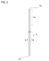
- FIG. 2 is a plan view of the movable shaft 10.
- the movable shaft 10 has a bent portion 10c.
- the bent portion 10c extends along the longitudinal direction of the movable shaft 10.
- the movable shaft 10 is configured to bend at the bent portion 10c by operating the hand operating portion 20.
- the movable shaft 10 in a state of being bent by the operation of the hand operation unit 20 is shown by a dotted line.
- FIG. 3 is a cross-sectional view taken along the line III-III of FIG.
- the movable shaft 10 has a first pipe member 11, a second pipe member 12, a braid 13, an exodermis 14, a pull wire 15, and a pull wire 16.
- the first pipe member 11 is a tubular member.
- the first tube member 11 is preferably formed of a polyetheretherketone resin (PEEK resin).
- PEEK resin polyetheretherketone resin
- the first tube member 11 may be made of a liquid crystal polymer, nylon, polycarbonate, polyimide, silicone, polyvinyl chloride (PVC), polyethylene or the like.
- the material constituting the first pipe member 11 is not limited to this.
- the first pipe member 11 has a distal end 11a and a proximal end 11b in the longitudinal direction thereof (see FIG. 4).
- the distal end 11a is located on the distal end 10a side and the proximal end 11b is located on the proximal end 10b side.
- the first pipe member 11 has an inner peripheral surface 11c and an outer peripheral surface 11d.
- a first groove 11da and a second groove 11db are formed on the outer peripheral surface 11d.
- the first groove 11da and the second groove 11db extend along the longitudinal direction of the first pipe member 11.
- the outer peripheral surface 11d is recessed toward the inner peripheral surface 11c side.
- the first groove 11da is located on the opposite side of the second groove 11db with the central axis of the first pipe member 11 interposed therebetween. The configuration of the other first pipe member 11 will be described later.
- the second pipe member 12 is inserted inside the first pipe member 11.
- the second pipe member 12 is a tubular member.
- the inside of the second pipe member 12 is hollow.
- a guide wire, a catheter (for example, a catheter used for ablation treatment of the heart) or the like is inserted into the second tube member 12.
- the wall thickness of the second pipe member 12 may be thinner than the wall thickness of the first pipe member 11 (the wall thickness of the first pipe member 11 may be thicker than the wall thickness of the second pipe member 12). ..
- the second pipe member 12 is a tubular member.
- the second tube member 12 is formed of, for example, a fluorine-based thermoplastic resin such as polytetrafluoroethylene resin (PTFE resin), PEEK resin, polyvinylidene fluoride resin (PVDF resin) and perfluoroalkoxy alkane resin (PFA resin).
- PTFE resin polytetrafluoroethylene resin
- PVDF resin polyvinylidene fluoride resin
- PFA resin perfluoroalkoxy alkane resin
- Braid 13 has a structure in which metal wires are woven into a net.
- the braid 13 is arranged so as to cover the outer peripheral surface 11d.
- the wires constituting the braid 13 are made of, for example, stainless steel.
- the outer skin 14 is arranged so as to cover the outer peripheral surface 11d and the braid 13.
- the outer skin 14 is formed of, for example, a fluororesin.
- the material constituting the exodermis 14 is not limited to this, and any biocompatible material can be applied.
- the pull wire 15 is slidably arranged in the groove 11da along the longitudinal direction of the first pipe member 11.
- the pull wire 15 is arranged along the longitudinal direction of the first pipe member 11 while facing the row of the first through holes 11f described later.
- the pull wire 16 is slidably arranged in the groove 11db along the longitudinal direction of the first pipe member 11.
- the pull wire 16 is arranged along the longitudinal direction of the first pipe member 11 while facing the row of the second through holes 11g, which will be described later.
- the pull wire 15 and the pull wire 16 are made of, for example, stainless steel. One end of the pull wire 15 and one end of the pull wire 16 are fixed to the distal end 10a.
- FIG. 4 is an enlarged plan view of the bent portion 11e of the first pipe member 11.
- the first pipe member 11 has a bent portion 11e.
- the bent portion 11e extends along the longitudinal direction of the first pipe member 11.
- the bent portion 11e is in a position corresponding to the bent portion 10c in a state of being arranged inside the movable shaft 10.
- the first pipe member 11 is configured to be bendable along the longitudinal direction of the first pipe member 11 at the bent portion 11e by operating the pull wire 15 and the pull wire 16 (hand operation portion 20).
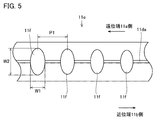
- FIG. 5 is a side view of the first pipe member 11 as viewed from the direction V of FIG.
- FIG. 6 is a side view of the first pipe member 11 as viewed from the direction VI of FIG.
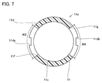
- FIG. 7 is a cross-sectional view taken along the line VII-VII of FIG.
- a plurality of first through holes 11f and a plurality of second through holes 11g are formed in the bent portion 11e.
- the first through hole 11f and the second through hole 11g are on opposite sides with respect to the central axis of the first pipe member 11.
- the first through hole 11f penetrates the first pipe member 11 along the direction from the outer peripheral surface 11d to the inner peripheral surface 11c.
- the first through holes 11f are formed in a row along the longitudinal direction of the first pipe member 11.
- the shape of the first through hole 11f is, for example, an elliptical shape.
- the elliptical long axis is along the circumferential direction of the first pipe member 11, and the elliptical short axis is along the longitudinal direction of the first pipe member 11.
- the width of the first through hole 11f in the longitudinal direction of the first pipe member 11 is defined as the width W1.
- the width of the first through hole 11f in the circumferential direction of the first pipe member 11 is defined as the width W2.
- the pitch between the two adjacent first through holes 11f in the longitudinal direction of the first pipe member 11 is defined as the pitch P1.
- the width W1 and / or the width W2 increases from the proximal end 11b side toward the distal end 11a side.
- the pitch P1 is, for example, constant.
- the shape of the second through hole 11g is, for example, an elliptical shape.
- the elliptical long axis is along the circumferential direction of the first pipe member 11, and the elliptical short axis is along the longitudinal direction of the first pipe member 11.
- the width of the second through hole 11g in the longitudinal direction of the first pipe member 11 is defined as the width W3.
- the width of the second through hole 11g in the circumferential direction of the first pipe member 11 is defined as the width W4.
- the pitch between the two adjacent second through holes 11g in the longitudinal direction of the first pipe member 11 is defined as the pitch P2.
- the width W3 and / or the width W4 increases from the proximal end 11b side to the distal end 11a side.
- the pitch P2 is, for example, constant.
- first through hole 11f and the second through hole 11g are closed by the second pipe member 12 from the inner peripheral surface 11c side.
- the width W1 and / or the width W2 is increased from the proximal end 11b side toward the distal end 11a, and the pitch P1 (pitch P2) is constant.
- the pitch P1 (pitch P2) may be reduced from the proximal end 11b side to the distal end 11a side, and the width W1 and / or the width W2 (width W3 and / or width W4) may be constant.
- the width W1, the width W2, the width W3 and the width W4 may be increased from the proximal end 11b side toward the distal end 11a side.
- Flexibility is imparted to the bent portion 11e by forming the first through hole 11f and the second through hole 11g in the bent portion 11e.
- the flexibility of the bent portion 11e increases from the proximal end 11b side to the distal end 11a side because the width W1 and / or the width W3 increases from the proximal end 11b side to the distal end 11a side. It is getting bigger toward.
- FIG. 8 is a side view of the first pipe member 11 according to the first modification.
- the first through hole 11f and the second through hole 11g may have, for example, a rectangular shape.
- the long side of the rectangular shape is along the circumferential direction of the first pipe member 11, and the short side of the rectangular shape is along the longitudinal direction of the first pipe member 11.
- the case where the corners of the first through hole 11f and the second through hole 11g (not shown) are rounded is also included in the "rectangular shape".
- the bent portion 11e becomes flexible. Has been granted.
- the first through hole 11f and the second through hole 11g (not shown) are closed by the second pipe member 12.
- the width W1 and / or the width W2 is from the proximal end 11b side to the distal end 11a side.
- the pitch P1 (pitch P2 (not shown)) becomes constant, for example.
- the flexibility of the bent portion 11e increases from the proximal end 11b side toward the distal end 11a side.
- the width W1 and / or the width W2 is increased from the proximal end 11b side toward the distal end 11a, and the pitch P1 (pitch P2) is constant.
- the pitch P1 (pitch P2) may be reduced from the proximal end 11b side to the distal end 11a side, and the width W1 and / or the width W2 (width W3 and / or width W4) may be constant.
- the width W1, the width W2, the width W3 and the width W4 may be increased from the proximal end 11b side toward the distal end 11a side.
- FIG. 9A is an enlarged plan view of the first pipe member 11 according to the second modification.
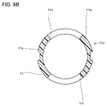
- FIG. 9B is a cross-sectional view taken along the line IXB-IXB of FIG. 9A.
- a plurality of third through holes 11h and a plurality of fourth through holes 11i may be formed in the first pipe member 11.
- the third through hole 11h and the fourth through hole 11i penetrate the first pipe member 11 along the direction from the outer peripheral surface 11d to the inner peripheral surface 11c.
- the third through holes 11h are formed so as to form a row along the longitudinal direction of the first pipe member 11, and the fourth through holes 11i are formed so as to form a row along the longitudinal direction of the first pipe member 11.
- the third through hole 11h is arranged between two first through holes 11f (second through holes 11g) adjacent to each other in the longitudinal direction of the first pipe member 11, and the fourth through hole 11i is the first pipe. It is arranged between two first through holes 11f (second through holes 11g) adjacent to each other in the longitudinal direction of the member 11.
- the third through hole 11h and the fourth through hole 11i are arranged to face each other in a direction orthogonal to the direction from the first through hole 11f to the second through hole 11g.
- the widths of the third through hole 11h and the fourth through hole 11i in the longitudinal direction of the first pipe member 11 increase from the proximal end 11b side to the distal end 11a side.
- the pitches of the two third through holes 11h adjacent to each other in the longitudinal direction of the first pipe member 11 and the pitches of the two fourth through holes 11i adjacent to each other in the longitudinal direction of the first pipe member 11 are, for example, constant.
- the first through hole 11f, the second through hole 11g, the third through hole 11h, and the fourth through hole 11i are closed by the second pipe member 12.
- the pitch and / or the pitch of the two third through holes 11h adjacent to each other in the longitudinal direction of the first pipe member 11 and / or adjacent to each other in the longitudinal direction of the first pipe member 11 2 may decrease from the proximal end 11b side to the distal end 11a side.
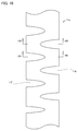
- FIG. 10 is an enlarged plan view of the first pipe member 11 according to the third modification.
- the second through hole 11g is arranged between two first through holes 11f adjacent to each other in the longitudinal direction of the first pipe member 11.
- the row of the first through hole 11f and the row of the second through hole 11g are opposite to each other with respect to the central axis of the first pipe member 11. That is, the first through hole 11f and the second through hole 11g are formed in a stepped manner in the longitudinal direction of the first pipe member 11.
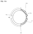
- FIG. 11A is a cross-sectional view taken along the line XIA-XIA of FIG.
- FIG. 11B is a cross-sectional view taken along the line XIB-XIB of FIG.
- the width W2 and the width W4 may be larger than 0.5 times the outer peripheral length of the first pipe member 11. As a result, the flexibility of the bent portion 11e can be further increased.
- the width W1 (not shown) and / or the width W2 (width W3 (not shown) and / or W4) is from the proximal end 11b side to the distal end 11a side.
- the pitch P1 (not shown) and / or the pitch P2 (not shown) are constant, for example.
- the pitch P1 (not shown) and / or the pitch P2 (not shown) becomes smaller from the proximal end 11b side to the distal end 11a side. You may.
- the first through hole 11f and the second through hole 11g are closed by the second pipe member 12 from the inner peripheral surface 11c side.
- the hand operation unit 20 has a first end 20a and a second end 20b.
- the second end 20b is the opposite end of the first end 20a.
- the movable shaft 10 passes through the inside of the hand operating portion 20, and the proximal end 10b reaches the second end 20b of the hand operating portion 20.
- the hand operation unit 20 has a grip unit 21 and a drive unit 22.
- the grip portion 21 is a portion for the user to grip the movable sheath 100 (hand operation portion 20).
- the drive unit 22 has, for example, a disk shape.
- the drive unit 22 can be rotationally driven around the central axis.
- the other end of the pull wire 15 and the other end of the pull wire 16 are fixed to the outer peripheral surface of the drive unit 22.
- the position on the outer peripheral surface of the drive unit 22 to which the other end of the pull wire 15 is fixed and the position on the outer peripheral surface of the drive unit 22 to which the other end of the pull wire 16 is fixed are related to the central axis of the drive unit 22. It is point symmetric.
- the pull wire 15 is pulled in the direction from the distal end 10a to the proximal end 10b, and the pull wire 16 is drawn from the proximal end 10b to the distal end 10a.
- the movable shaft 10 bends into the shape shown by the dotted line in FIG.
- the drive unit 22 is rotated in the reverse direction around the central axis, the pull wire 15 is pushed out along the direction from the proximal end 10b to the distal end 10a, and the pull wire 16 is pushed from the distal end 10a to the proximal end 10b. It is pulled in along the direction in which the movable shaft 10 returns to its original shape.
- the drive unit 22 is further rotated in the reverse direction around the central axis, the movable shaft 10 bends to the side opposite to the shape shown by the dotted line in FIG.
- the hand operation unit 20 further has a hemostatic valve 30.
- the inside of the hemostatic valve 30 is hollow.
- the hemostatic valve 30 is attached to the second end 20b.
- the inside of the hemostatic valve 30 communicates with the inside of the movable shaft 10 (more specifically, the inside of the second pipe member 12).
- the hemostatic valve 30 is provided with an insertion port. A guide wire, a catheter, or the like is inserted into the movable shaft 10 from this insertion port.
- Tube 40 and three-way stopcock 50 The tube 40 is connected to the hemostatic valve 30 at one end. The inside of the tube 40 communicates with the inside of the hemostatic valve 30. A three-way stopcock 50 is attached to the other end of the tube 40. By attaching a syringe (not shown) to the three-way stopcock 50, air or blood is removed from the inside of the movable shaft 10 or a chemical solution is supplied to the inside of the movable shaft 10.
- the effect of the movable sheath 100 will be described below.
- the distance between the opening edges of the first through holes 11f (second through holes 11g) facing each other in the longitudinal direction of the first pipe member 11 narrows as the bent portion 11e bends, and finally, The opening edges of the first through hole 11f (second through hole 11g) facing each other in the longitudinal direction of the first pipe member 11 come into contact with each other.
- the bending deformation of the bent portion 11e is regulated at a certain position (hereinafter, the bending angle of the bent portion 11e in this state is referred to as an "upper limit bending angle").
- the width W1 (width W3) increases from the proximal end 11b side toward the distal end 11a side. Therefore, the upper limit bending angle of the bent portion 11e increases from the proximal end 11b side toward the distal end 11a side.
- the pull wire 15 (pull wire 16) is pulled.
- the bending method of the bent portion 11e does not change significantly on the proximal end 11b side, the curved shape of the bent portion 11e is stable.
- the width W1 (flexibility of the bent portion 11e) increases from the proximal end 11b side toward the distal end 11a side, so that the curved shape at the bent portion 11e It is possible to improve the controllability of the.
- movable sheath 200 the configuration of the movable sheath (hereinafter referred to as “movable sheath 200”) according to the second embodiment will be described.
- the points different from the configuration of the movable sheath 100 will be mainly described, and the duplicated description will not be repeated.
- the movable sheath 200 has a movable shaft 10, a hand operation unit 20, a hemostatic valve 30, a tube 40, and a three-way stopcock 50.
- a first through hole 11f and a second through hole 11g are formed in the bent portion 11e, and the flexibility of the bent portion 11e increases from the proximal end 11b side to the distal end 11a side. It has become.
- the configuration of the movable sheath 200 is common to the configuration of the movable sheath 100.
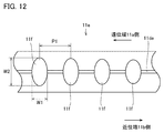
- FIG. 12 is a side view of the first pipe member 11 at the bent portion 11e of the movable sheath 200.
- the width W1 and the pitch P1 are constant.
- the width W3 (not shown) and the pitch P2 (not shown) are also constant.
- the width W2 and / or the width W4 (not shown) increases from the proximal end 11b side to the distal end 11a side.
- the width W2 (width W4) increases from the proximal end 11b side to the distal end 11a side, and the flexibility of the bent portion 11e increases from the proximal end 11b side to the distal end. It becomes larger toward the 11a side. Therefore, according to the movable sheath 200, it is possible to improve the controllability of the curved shape in the bent portion 11e as in the movable sheath 100.
- movable sheath 300 the configuration of the movable sheath (hereinafter referred to as “movable sheath 300”) according to the third embodiment will be described.
- the points different from the configuration of the movable sheath 100 will be mainly described, and the duplicated description will not be repeated.
- the movable sheath 300 has a movable shaft 10, a hand operation unit 20, a hemostatic valve 30, a tube 40, and a three-way stopcock 50.
- a first through hole 11f and a second through hole 11g are formed in the bent portion 11e, and the flexibility of the bent portion 11e increases from the proximal end 11b side to the distal end 11a side. It has become.
- the configuration of the movable sheath 300 is common to the configuration of the movable sheath 100.
- FIG. 13 is a side view of the first pipe member 11 in the bent portion 11e of the movable sheath 300.
- the width W1, the width W2, the width W3 (not shown) and the width W4 (not shown) are constant.
- the pitch P1 and / or the pitch P2 (not shown) becomes smaller from the proximal end 11b side to the distal end 11a side.
- the pitch P1 decreases from the proximal end 11b side toward the distal end 11a, and the flexibility of the bent portion 11e decreases from the proximal end 11b side to the distal end. It becomes larger toward the 11a side. Therefore, according to the movable sheath 300, it is possible to improve the controllability of the curved shape at the bent portion 11e, similarly to the movable sheath 100.
- movable sheath 400 the configuration of the movable sheath (hereinafter referred to as “movable sheath 400”) according to the fourth embodiment will be described.
- the points different from the configuration of the movable sheath 100 will be mainly described, and the duplicated description will not be repeated.
- the movable sheath 400 has a movable shaft 10, a hand operation unit 20, a hemostatic valve 30, a tube 40, and a three-way stopcock 50.
- a first through hole 11f and a second through hole 11g are formed in the bent portion 11e, and the flexibility of the bent portion 11e increases from the proximal end 11b side to the distal end 11a side. It has become.
- the configuration of the movable sheath 300 is common to the configuration of the movable sheath 100.
- FIG. 14 is a side view of the first pipe member 11 in the bent portion 11e of the movable sheath 400.
- the width W2 and width W4 (not shown) and the pitch P1 and pitch P2 (not shown) are constant.
- the width W1 and / or the width W3 (not shown) increases from the proximal end 11b side to the distal end 11a side.
- the width W1 increases from the proximal end 11b side to the distal end 11a side, and the flexibility of the bent portion 11e increases at the proximal end. It increases from the 11b side toward the distal end 11a side. Therefore, according to the movable sheath 400, it is possible to improve the controllability of the curved shape at the bent portion 11e, similarly to the movable sheath 100.
- the movable sheath is exemplified as the medical device having the movable shaft 10, but the medical device having the movable shaft 10 is not limited to this.
- Other examples of medical devices having a movable shaft 10 include catheters and endoscopes.
- This embodiment is particularly advantageously applied to a movable sheath into which a catheter for treating cardiac ablation is inserted.
- 10 movable shaft 20 hand operation part, 20a first end, 20b second end, 30 hemostatic valve, 40 tube, 50 three-way stopcock, 10a distal end, 10b proximal end, 10c bending part, 11 first tube member, 11a distal end, 11b proximal end, 11c inner peripheral surface, 11d outer peripheral surface, 11da first groove, 11db second groove, 11e bent part, 11f first through hole, 11g second through hole, 11h third through hole , 11i 4th through hole, 12 2nd pipe member, 13 braid, 14 outer skin, 15 pull wire, 16 pull wire, 21 grip part, 22 drive part, P1, P2 pitch, W1, W2, W3, W4 width, 100,200 , 300, 400 Movable sheath.
Abstract
A movable shaft according to the present invention comprises a tube member. The tube member comprises a proximal end and a distal end in the lengthwise direction of the tube member. The tube member comprises a flexing part that extends along the lengthwise direction and that is configured so as to be capable of flexing. The flexibility of the flexing part increases from the proximal end side thereof toward the distal end side thereof.
Description
本発明は、可動シャフト及び可動シャフトを有する医療器具に関する。
The present invention relates to a movable shaft and a medical device having a movable shaft.
特許文献1(特表2006-507073号公報)には、医療用器具に用いられるチューブ(以下においては、単に「チューブ」とする)が記載されている。特許文献1に記載のチューブの外周面には、切り欠きが形成されている。この切り欠きは、チューブの長手方向に沿って間隔を空けて配列されている。特許文献1に記載のチューブは、切り欠きが形成されている部分に可撓性が付与されているため、当該部分において屈曲可能になっている。
Patent Document 1 (Japanese Patent Publication No. 2006-507073) describes a tube used for a medical device (hereinafter, simply referred to as a "tube"). A notch is formed on the outer peripheral surface of the tube described in Patent Document 1. The notches are spaced apart along the longitudinal direction of the tube. The tube described in Patent Document 1 is flexible at a portion where the notch is formed, so that the tube can be bent at the portion.
特許文献1に記載のチューブにおいて、チューブの長手方向における切り欠きの幅が、遠位端側から近位端側に向かうにしたがって大きくなっている。つまり、特許文献1に記載のチューブにおいては、切り欠きが形成されている部分の可撓性が、遠位端側から近位端側に向かうにしたがって大きくなっている。本発明者らが見出した知見によると、特許文献1に記載のチューブは、屈曲部における曲線形状のコントロール性に改善の余地がある。
In the tube described in Patent Document 1, the width of the notch in the longitudinal direction of the tube increases from the distal end side to the proximal end side. That is, in the tube described in Patent Document 1, the flexibility of the portion where the notch is formed increases from the distal end side to the proximal end side. According to the findings found by the present inventors, the tube described in Patent Document 1 has room for improvement in the controllability of the curved shape at the bent portion.
本発明は、上記のような従来技術の問題点に鑑みてなされたものである。より具体的には、本発明は、管部材の屈曲部における曲線形状のコントロール性が改善された可動シャフト及び可動シャフトを有する医療器具を提供するものである。
The present invention has been made in view of the above-mentioned problems of the prior art. More specifically, the present invention provides a medical device having a movable shaft and a movable shaft with improved controllability of a curved shape at a bent portion of a pipe member.
本発明の一態様に係る可動シャフトは、管部材を備えている。管部材は、管部材の長手方向において、近位端と、遠位端とを有している。管部材は、長手方向に沿って延在し、屈曲可能に構成された屈曲部を有している。屈曲部の可撓性は、近位端側から遠位端側に向かうにしたがって大きくなっている。
The movable shaft according to one aspect of the present invention includes a pipe member. The tube member has a proximal end and a distal end in the longitudinal direction of the tube member. The pipe member extends along the longitudinal direction and has a bendable portion configured to be bendable. The flexibility of the bent portion increases from the proximal end side to the distal end side.
上記の可動シャフトにおいて、管部材は、内周面と、外周面とを有していてもよい。屈曲部には、外周面から内周面に向かう方向に管部材を貫通している貫通穴が長手方向に沿って列をなすように間隔を空けて複数形成されていてもよい。長手方向において隣り合う2つの貫通穴のピッチが、近位端側から遠位端側に向かうにしたがって小さくなっていてもよい。
In the above movable shaft, the pipe member may have an inner peripheral surface and an outer peripheral surface. A plurality of through holes penetrating the pipe member in the direction from the outer peripheral surface to the inner peripheral surface may be formed in the bent portion at intervals so as to form a row along the longitudinal direction. The pitch of two adjacent through holes in the longitudinal direction may decrease from the proximal end side to the distal end side.
上記の可動シャフトにおいて、長手方向における貫通穴の幅及び管部材の周方向における貫通穴の幅の少なくともいずれかが、近位端側から遠位端側に向かうにしたがって大きくなっていてもよい。
In the above movable shaft, at least one of the width of the through hole in the longitudinal direction and the width of the through hole in the circumferential direction of the pipe member may increase from the proximal end side to the distal end side.
上記の可動シャフトは、貫通穴と対向するように長手方向に沿って配置されたプルワイヤをさらに備えていてもよい。
The movable shaft may further include a pull wire arranged along the longitudinal direction so as to face the through hole.
本発明の一態様に係る医療器具は、上記の可動シャフトを備える。本発明の一態様に係る医療器具は、プルワイヤを引くことにより屈曲部を曲げるように構成されている。
The medical device according to one aspect of the present invention includes the above-mentioned movable shaft. The medical device according to one aspect of the present invention is configured to bend a bent portion by pulling a pull wire.
本発明の一態様に係る可動シャフト及び可動シャフトを有する医療器具によると、管部材の屈曲部における曲線形状のコントロール性を改善することが可能となる。
According to the movable shaft and the medical device having the movable shaft according to one aspect of the present invention, it is possible to improve the controllability of the curved shape at the bent portion of the pipe member.
実施形態の詳細を、図面を参照しながら説明する。以下の図面においては、同一又は相当する部分に同一の参照符号を付し、重複する説明は繰り返さない。
The details of the embodiment will be explained with reference to the drawings. In the following drawings, the same or corresponding parts are designated by the same reference numerals, and duplicate explanations will not be repeated.
(第1実施形態)
以下に、第1実施形態に係る可動シース(以下においては、「可動シース100」とする)の構成を説明する。 (First Embodiment)
Hereinafter, the configuration of the movable sheath (hereinafter referred to as “movable sheath 100”) according to the first embodiment will be described.
以下に、第1実施形態に係る可動シース(以下においては、「可動シース100」とする)の構成を説明する。 (First Embodiment)
Hereinafter, the configuration of the movable sheath (hereinafter referred to as “
<可動シース100の概略構成>
図1は、可動シース100の平面図である。図1に示されるように、可動シース100は、可動シャフト10と、手元操作部20と、止血弁30と、チューブ40と、三方活栓50とを有している。可動シャフト10は、その長手方向において、遠位端10aと近位端10bとを有している。近位端10b側には、手元操作部20が取り付けられている。 <Approximate configuration ofmovable sheath 100>
FIG. 1 is a plan view of themovable sheath 100. As shown in FIG. 1, the movable sheath 100 includes a movable shaft 10, a hand operation unit 20, a hemostatic valve 30, a tube 40, and a three-way stopcock 50. The movable shaft 10 has a distal end 10a and a proximal end 10b in its longitudinal direction. A hand operation unit 20 is attached to the proximal end 10b side.
図1は、可動シース100の平面図である。図1に示されるように、可動シース100は、可動シャフト10と、手元操作部20と、止血弁30と、チューブ40と、三方活栓50とを有している。可動シャフト10は、その長手方向において、遠位端10aと近位端10bとを有している。近位端10b側には、手元操作部20が取り付けられている。 <Approximate configuration of
FIG. 1 is a plan view of the
図2は、可動シャフト10の平面図である。可動シャフト10は、屈曲部10cを有している。屈曲部10cは、可動シャフト10の長手方向に沿って延在している。可動シャフト10は、手元操作部20を操作することにより、屈曲部10cにおいて曲がるように構成されている。なお、図1中において、手元操作部20の操作により曲げられた状態の可動シャフト10は、点線により示されている。
FIG. 2 is a plan view of the movable shaft 10. The movable shaft 10 has a bent portion 10c. The bent portion 10c extends along the longitudinal direction of the movable shaft 10. The movable shaft 10 is configured to bend at the bent portion 10c by operating the hand operating portion 20. In FIG. 1, the movable shaft 10 in a state of being bent by the operation of the hand operation unit 20 is shown by a dotted line.
図3は、図2のIII-IIIにおける断面図である。図3に示されるように、可動シャフト10は、第1管部材11と、第2管部材12と、編組13と、外皮14と、プルワイヤ15及びプルワイヤ16とを有している。
FIG. 3 is a cross-sectional view taken along the line III-III of FIG. As shown in FIG. 3, the movable shaft 10 has a first pipe member 11, a second pipe member 12, a braid 13, an exodermis 14, a pull wire 15, and a pull wire 16.
第1管部材11は、管状の部材である。第1管部材11は、好ましくは、ポリエーテルエーテルケトン樹脂(PEEK樹脂)により形成されている。第1管部材11は、液晶ポリマー、ナイロン、ポリカーボネート、ポリイミド、シリコーン、ポリ塩化ビニル(PVC)、ポリエチレン等により形成されていてもよい。第1管部材11を構成する材料は、これに限られない。
The first pipe member 11 is a tubular member. The first tube member 11 is preferably formed of a polyetheretherketone resin (PEEK resin). The first tube member 11 may be made of a liquid crystal polymer, nylon, polycarbonate, polyimide, silicone, polyvinyl chloride (PVC), polyethylene or the like. The material constituting the first pipe member 11 is not limited to this.
第1管部材11は、その長手方向において、遠位端11aと近位端11bとを有している(図4参照)。遠位端11aは遠位端10a側に位置しており、近位端11bは近位端10b側に位置している。
The first pipe member 11 has a distal end 11a and a proximal end 11b in the longitudinal direction thereof (see FIG. 4). The distal end 11a is located on the distal end 10a side and the proximal end 11b is located on the proximal end 10b side.
第1管部材11は、内周面11cと外周面11dとを有している。外周面11dには、第1溝11da及び第2溝11dbが形成されている。第1溝11da及び第2溝11dbは、第1管部材11の長手方向に沿って延在している。第1溝11da及び第2溝11dbにおいて、外周面11dは、内周面11c側に向かって窪んでいる。第1溝11daは、第1管部材11の中心軸を挟んで第2溝11dbの反対側に位置している。その他の第1管部材11の構成に関しては、後述する。
The first pipe member 11 has an inner peripheral surface 11c and an outer peripheral surface 11d. A first groove 11da and a second groove 11db are formed on the outer peripheral surface 11d. The first groove 11da and the second groove 11db extend along the longitudinal direction of the first pipe member 11. In the first groove 11da and the second groove 11db, the outer peripheral surface 11d is recessed toward the inner peripheral surface 11c side. The first groove 11da is located on the opposite side of the second groove 11db with the central axis of the first pipe member 11 interposed therebetween. The configuration of the other first pipe member 11 will be described later.
第2管部材12は、第1管部材11の内部に挿入されている。第2管部材12は、管状の部材である。可動シャフト10が可動シースに適用される場合、第2管部材12の内部は中空になっている。第2管部材12の内部には、ガイドワイヤ、カテーテル(例えば、心臓のアブレーション治療に用いられるカテーテル)等が挿入される。第2管部材12の肉厚は、第1管部材11の肉厚よりも薄くてもよい(第1管部材11の肉厚は、第2管部材12の肉厚よりも厚くてもよい)。第2管部材12は、管状の部材である。
The second pipe member 12 is inserted inside the first pipe member 11. The second pipe member 12 is a tubular member. When the movable shaft 10 is applied to the movable sheath, the inside of the second pipe member 12 is hollow. A guide wire, a catheter (for example, a catheter used for ablation treatment of the heart) or the like is inserted into the second tube member 12. The wall thickness of the second pipe member 12 may be thinner than the wall thickness of the first pipe member 11 (the wall thickness of the first pipe member 11 may be thicker than the wall thickness of the second pipe member 12). .. The second pipe member 12 is a tubular member.
第2管部材12は、例えば、ポリテトラフルオロエチレン樹脂(PTFE樹脂)、PEEK樹脂、ポリビニリデンフルオライド樹脂(PVDF樹脂)及びペルフルオロアルコキシフッ素樹脂(PFA樹脂)等のフッ素系の熱可塑性樹脂により形成されている。但し、第2管部材12を構成している材料は、これに限られず、内部に挿入されるガイドワイヤやカテーテル等による操作上の潤滑性を満足する樹脂により形成されていればよい。
The second tube member 12 is formed of, for example, a fluorine-based thermoplastic resin such as polytetrafluoroethylene resin (PTFE resin), PEEK resin, polyvinylidene fluoride resin (PVDF resin) and perfluoroalkoxy alkane resin (PFA resin). Has been done. However, the material constituting the second pipe member 12 is not limited to this, and may be made of a resin that satisfies the operational lubricity of a guide wire, a catheter, or the like inserted inside.
編組13は、金属製のワイヤを網状に編み込んだ構造である。編組13は、外周面11dを覆うように配置されている。編組13を構成しているワイヤは、例えば、ステンレス鋼により形成されている。外皮14は、外周面11d及び編組13を覆うように配置されている。外皮14は、例えば、フッ素樹脂により形成されている。外皮14を構成する材料は、これに限られず、生体適合性のある材料であれば適用可能である。
Braid 13 has a structure in which metal wires are woven into a net. The braid 13 is arranged so as to cover the outer peripheral surface 11d. The wires constituting the braid 13 are made of, for example, stainless steel. The outer skin 14 is arranged so as to cover the outer peripheral surface 11d and the braid 13. The outer skin 14 is formed of, for example, a fluororesin. The material constituting the exodermis 14 is not limited to this, and any biocompatible material can be applied.
プルワイヤ15は、第1管部材11の長手方向に沿ってスライド可能に溝11da内に配置されている。プルワイヤ15は、後述する第1貫通穴11fの列に対向しながら第1管部材11の長手方向に沿って配置されている。プルワイヤ16は、第1管部材11の長手方向に沿ってスライド可能に溝11db内に配置されている。プルワイヤ16は、後述する第2貫通穴11gの列に対向しながら第1管部材11の長手方向に沿って配置されている。プルワイヤ15及びプルワイヤ16は、例えば、ステンレス鋼により形成されている。プルワイヤ15の一方端及びプルワイヤ16の一方端は、遠位端10aに固定されている。
The pull wire 15 is slidably arranged in the groove 11da along the longitudinal direction of the first pipe member 11. The pull wire 15 is arranged along the longitudinal direction of the first pipe member 11 while facing the row of the first through holes 11f described later. The pull wire 16 is slidably arranged in the groove 11db along the longitudinal direction of the first pipe member 11. The pull wire 16 is arranged along the longitudinal direction of the first pipe member 11 while facing the row of the second through holes 11g, which will be described later. The pull wire 15 and the pull wire 16 are made of, for example, stainless steel. One end of the pull wire 15 and one end of the pull wire 16 are fixed to the distal end 10a.
<第1管部材11の詳細構成>
図4は、第1管部材11の屈曲部11eにおける拡大平面図である。図4に示されるように、第1管部材11は、屈曲部11eを有している。屈曲部11eは、第1管部材11の長手方向に沿って延在している。屈曲部11eは、可動シャフト10の内部に配置された状態において、屈曲部10cに対応した位置にある。第1管部材11は、屈曲部11eにおいて、プルワイヤ15及びプルワイヤ16(手元操作部20)の操作により第1管部材11の長手方向に沿って屈曲可能に構成されている。 <Detailed configuration of thefirst pipe member 11>
FIG. 4 is an enlarged plan view of thebent portion 11e of the first pipe member 11. As shown in FIG. 4, the first pipe member 11 has a bent portion 11e. The bent portion 11e extends along the longitudinal direction of the first pipe member 11. The bent portion 11e is in a position corresponding to the bent portion 10c in a state of being arranged inside the movable shaft 10. The first pipe member 11 is configured to be bendable along the longitudinal direction of the first pipe member 11 at the bent portion 11e by operating the pull wire 15 and the pull wire 16 (hand operation portion 20).
図4は、第1管部材11の屈曲部11eにおける拡大平面図である。図4に示されるように、第1管部材11は、屈曲部11eを有している。屈曲部11eは、第1管部材11の長手方向に沿って延在している。屈曲部11eは、可動シャフト10の内部に配置された状態において、屈曲部10cに対応した位置にある。第1管部材11は、屈曲部11eにおいて、プルワイヤ15及びプルワイヤ16(手元操作部20)の操作により第1管部材11の長手方向に沿って屈曲可能に構成されている。 <Detailed configuration of the
FIG. 4 is an enlarged plan view of the
図5は、図4の方向Vから見た第1管部材11の側面図である。図6は、図4の方向VIから見た第1管部材11の側面図である。図7は、図4のVII-VIIにおける断面図である。図4、図5、図6及び図7に示されるように、屈曲部11eには、複数の第1貫通穴11fと、複数の第2貫通穴11gとが形成されている。第1貫通穴11f及び第2貫通穴11gは、第1管部材11の中心軸に関して互いに反対側にある。
FIG. 5 is a side view of the first pipe member 11 as viewed from the direction V of FIG. FIG. 6 is a side view of the first pipe member 11 as viewed from the direction VI of FIG. FIG. 7 is a cross-sectional view taken along the line VII-VII of FIG. As shown in FIGS. 4, 5, 6 and 7, a plurality of first through holes 11f and a plurality of second through holes 11g are formed in the bent portion 11e. The first through hole 11f and the second through hole 11g are on opposite sides with respect to the central axis of the first pipe member 11.
第1貫通穴11fは、外周面11dから内周面11cに向かう方向に沿って、第1管部材11を貫通している。第1貫通穴11fは、第1管部材11の長手方向に沿って、列をなすように形成されている。
The first through hole 11f penetrates the first pipe member 11 along the direction from the outer peripheral surface 11d to the inner peripheral surface 11c. The first through holes 11f are formed in a row along the longitudinal direction of the first pipe member 11.
第1貫通穴11fの形状は、例えば、楕円形状である。この楕円形状の長軸は、第1管部材11の周方向に沿っており、この楕円形状の短軸は、第1管部材11の長手方向に沿っている。第1管部材11の長手方向における第1貫通穴11fの幅を、幅W1とする。第1管部材11の周方向における第1貫通穴11fの幅を、幅W2とする。第1管部材11の長手方向において隣り合う2つの第1貫通穴11fの間のピッチを、ピッチP1とする。幅W1及び/又は幅W2は、近位端11b側から遠位端11a側に向かうにしたがって、大きくなっている。ピッチP1は、例えば、一定となっている。
The shape of the first through hole 11f is, for example, an elliptical shape. The elliptical long axis is along the circumferential direction of the first pipe member 11, and the elliptical short axis is along the longitudinal direction of the first pipe member 11. The width of the first through hole 11f in the longitudinal direction of the first pipe member 11 is defined as the width W1. The width of the first through hole 11f in the circumferential direction of the first pipe member 11 is defined as the width W2. The pitch between the two adjacent first through holes 11f in the longitudinal direction of the first pipe member 11 is defined as the pitch P1. The width W1 and / or the width W2 increases from the proximal end 11b side toward the distal end 11a side. The pitch P1 is, for example, constant.
第2貫通穴11gの形状は、例えば、楕円形状である。この楕円形状の長軸は、第1管部材11の周方向に沿っており、この楕円形状の短軸は、第1管部材11の長手方向に沿っている。第1管部材11の長手方向における第2貫通穴11gの幅を、幅W3とする。第1管部材11の周方向における第2貫通穴11gの幅を、幅W4とする。第1管部材11の長手方向において隣り合う2つの第2貫通穴11gの間のピッチを、ピッチP2とする。幅W3及び/又は幅W4は、近位端11b側から遠位端11a側に向かうにしたがって、大きくなっている。ピッチP2は、例えば、一定となっている。
The shape of the second through hole 11g is, for example, an elliptical shape. The elliptical long axis is along the circumferential direction of the first pipe member 11, and the elliptical short axis is along the longitudinal direction of the first pipe member 11. The width of the second through hole 11g in the longitudinal direction of the first pipe member 11 is defined as the width W3. The width of the second through hole 11g in the circumferential direction of the first pipe member 11 is defined as the width W4. The pitch between the two adjacent second through holes 11g in the longitudinal direction of the first pipe member 11 is defined as the pitch P2. The width W3 and / or the width W4 increases from the proximal end 11b side to the distal end 11a side. The pitch P2 is, for example, constant.
なお、図示されていないが、第1貫通穴11f及び第2貫通穴11gは、内周面11c側から第2管部材12により閉塞されている。
Although not shown, the first through hole 11f and the second through hole 11g are closed by the second pipe member 12 from the inner peripheral surface 11c side.
上記の例においては、幅W1及び/又は幅W2(幅W3及び/又は幅W4)を近位端11b側から遠位端11a側に向かうにしたがって大きくするとともに、ピッチP1(ピッチP2)を一定としたが、ピッチP1(ピッチP2)を近位端11b側から遠位端11a側に向かうにしたがって小さくするとともに、幅W1及び/又は幅W2(幅W3及び/又は幅W4)を一定としてもよい。また、幅W1、幅W2、幅W3及び幅W4を近位端11b側から遠位端11a側に向かうにしたがって大きくしてもよい。
In the above example, the width W1 and / or the width W2 (width W3 and / or width W4) is increased from the proximal end 11b side toward the distal end 11a, and the pitch P1 (pitch P2) is constant. However, the pitch P1 (pitch P2) may be reduced from the proximal end 11b side to the distal end 11a side, and the width W1 and / or the width W2 (width W3 and / or width W4) may be constant. Good. Further, the width W1, the width W2, the width W3 and the width W4 may be increased from the proximal end 11b side toward the distal end 11a side.
屈曲部11eに第1貫通穴11f及び第2貫通穴11gが形成されていることにより、屈曲部11eに可撓性が付与されている。幅W1及び/又は幅W3が近位端11b側から遠位端11a側に向かうにしたがって大きくなっていることにより、屈曲部11eの可撓性は、近位端11b側から遠位端11a側に向かうにしたがって大きくなっている。
Flexibility is imparted to the bent portion 11e by forming the first through hole 11f and the second through hole 11g in the bent portion 11e. The flexibility of the bent portion 11e increases from the proximal end 11b side to the distal end 11a side because the width W1 and / or the width W3 increases from the proximal end 11b side to the distal end 11a side. It is getting bigger toward.
<第1管部材11の変形例>
図8は、第1変形例に係る第1管部材11の側面図である。図8に示されるように、第1貫通穴11f及び第2貫通穴11g(図示せず)は、例えば、矩形形状を有していてもよい。この矩形形状の長辺は、第1管部材11の周方向に沿っており、この矩形形状の短辺は、第1管部材11の長手方向に沿っている。第1貫通穴11f及び第2貫通穴11g(図示せず)の角が丸まっている場合も、「矩形形状」に含まれる。第1変形例に係る第1管部材11においては、第1貫通穴11f及び第2貫通穴11g(図示せず)が屈曲部11eに形成されていることにより、屈曲部11eに可撓性が付与されている。図示されていないが、第1貫通穴11f及び第2貫通穴11g(図示せず)は、第2管部材12により閉塞されている。 <Modification example of thefirst pipe member 11>
FIG. 8 is a side view of thefirst pipe member 11 according to the first modification. As shown in FIG. 8, the first through hole 11f and the second through hole 11g (not shown) may have, for example, a rectangular shape. The long side of the rectangular shape is along the circumferential direction of the first pipe member 11, and the short side of the rectangular shape is along the longitudinal direction of the first pipe member 11. The case where the corners of the first through hole 11f and the second through hole 11g (not shown) are rounded is also included in the "rectangular shape". In the first pipe member 11 according to the first modification, since the first through hole 11f and the second through hole 11g (not shown) are formed in the bent portion 11e, the bent portion 11e becomes flexible. Has been granted. Although not shown, the first through hole 11f and the second through hole 11g (not shown) are closed by the second pipe member 12.
図8は、第1変形例に係る第1管部材11の側面図である。図8に示されるように、第1貫通穴11f及び第2貫通穴11g(図示せず)は、例えば、矩形形状を有していてもよい。この矩形形状の長辺は、第1管部材11の周方向に沿っており、この矩形形状の短辺は、第1管部材11の長手方向に沿っている。第1貫通穴11f及び第2貫通穴11g(図示せず)の角が丸まっている場合も、「矩形形状」に含まれる。第1変形例に係る第1管部材11においては、第1貫通穴11f及び第2貫通穴11g(図示せず)が屈曲部11eに形成されていることにより、屈曲部11eに可撓性が付与されている。図示されていないが、第1貫通穴11f及び第2貫通穴11g(図示せず)は、第2管部材12により閉塞されている。 <Modification example of the
FIG. 8 is a side view of the
第1変形例に係る第1管部材11において、幅W1及び/又は幅W2(幅W3(図示せず)及び/又はW4(図示せず))が近位端11b側から遠位端11a側に向かうにしたがって大きくなっており、ピッチP1(ピッチP2(図示せず))は例えば一定となっている。これにより、屈曲部11eの可撓性は、近位端11b側から遠位端11a側に向かうにしたがって大きくなっている。
In the first pipe member 11 according to the first modification, the width W1 and / or the width W2 (width W3 (not shown) and / or W4 (not shown)) is from the proximal end 11b side to the distal end 11a side. The pitch P1 (pitch P2 (not shown)) becomes constant, for example. As a result, the flexibility of the bent portion 11e increases from the proximal end 11b side toward the distal end 11a side.
上記の例においては、幅W1及び/又は幅W2(幅W3及び/又は幅W4)を近位端11b側から遠位端11a側に向かうにしたがって大きくするとともに、ピッチP1(ピッチP2)を一定としたが、ピッチP1(ピッチP2)を近位端11b側から遠位端11a側に向かうにしたがって小さくするとともに、幅W1及び/又は幅W2(幅W3及び/又は幅W4)を一定としてもよい。また、幅W1、幅W2、幅W3及び幅W4を近位端11b側から遠位端11a側に向かうにしたがって大きくしてもよい。
In the above example, the width W1 and / or the width W2 (width W3 and / or width W4) is increased from the proximal end 11b side toward the distal end 11a, and the pitch P1 (pitch P2) is constant. However, the pitch P1 (pitch P2) may be reduced from the proximal end 11b side to the distal end 11a side, and the width W1 and / or the width W2 (width W3 and / or width W4) may be constant. Good. Further, the width W1, the width W2, the width W3 and the width W4 may be increased from the proximal end 11b side toward the distal end 11a side.
図9Aは、第2変形例に係る第1管部材11の拡大平面図である。図9Bは、図9AのIXB-IXBにおける断面図である。第1管部材11には、複数の第3貫通穴11h及び複数の第4貫通穴11iが形成されていてもよい。
FIG. 9A is an enlarged plan view of the first pipe member 11 according to the second modification. FIG. 9B is a cross-sectional view taken along the line IXB-IXB of FIG. 9A. A plurality of third through holes 11h and a plurality of fourth through holes 11i may be formed in the first pipe member 11.
第3貫通穴11h及び第4貫通穴11iは、外周面11dから内周面11cに向かう方向に沿って、第1管部材11を貫通している。第3貫通穴11hは第1管部材11の長手方向に沿って列をなすように形成されており、第4貫通穴11iは第1管部材11の長手方向に沿って列をなすように形成されている。第3貫通穴11hは、第1管部材11の長手方向において隣り合う2つの第1貫通穴11f(第2貫通穴11g)の間に配置されており、第4貫通穴11iは、第1管部材11の長手方向において隣り合う2つの第1貫通穴11f(第2貫通穴11g)の間に配置されている。
The third through hole 11h and the fourth through hole 11i penetrate the first pipe member 11 along the direction from the outer peripheral surface 11d to the inner peripheral surface 11c. The third through holes 11h are formed so as to form a row along the longitudinal direction of the first pipe member 11, and the fourth through holes 11i are formed so as to form a row along the longitudinal direction of the first pipe member 11. Has been done. The third through hole 11h is arranged between two first through holes 11f (second through holes 11g) adjacent to each other in the longitudinal direction of the first pipe member 11, and the fourth through hole 11i is the first pipe. It is arranged between two first through holes 11f (second through holes 11g) adjacent to each other in the longitudinal direction of the member 11.
第3貫通穴11h及び第4貫通穴11iは、第1貫通穴11fから第2貫通穴11gに向かう方向と直交する方向において互いに対向配置されている。第1管部材11の長手方向における第3貫通穴11h及び第4貫通穴11iの幅は、近位端11b側から遠位端11a側に向かうにしたがって大きくなっている。第1管部材11の長手方向において隣り合う2つの第3貫通穴11hのピッチ及び第1管部材11の長手方向において隣り合う2つの第4貫通穴11iのピッチは、例えば一定である。図示されていないが、第1貫通穴11f、第2貫通穴11g、第3貫通穴11h及び第4貫通穴11iは、第2管部材12により閉塞されている。
The third through hole 11h and the fourth through hole 11i are arranged to face each other in a direction orthogonal to the direction from the first through hole 11f to the second through hole 11g. The widths of the third through hole 11h and the fourth through hole 11i in the longitudinal direction of the first pipe member 11 increase from the proximal end 11b side to the distal end 11a side. The pitches of the two third through holes 11h adjacent to each other in the longitudinal direction of the first pipe member 11 and the pitches of the two fourth through holes 11i adjacent to each other in the longitudinal direction of the first pipe member 11 are, for example, constant. Although not shown, the first through hole 11f, the second through hole 11g, the third through hole 11h, and the fourth through hole 11i are closed by the second pipe member 12.
なお、第2変形例に係る第1管部材11において、第1管部材11の長手方向において隣り合う2つの第3貫通穴11hのピッチ及び/又は第1管部材11の長手方向において隣り合う2つの第4貫通穴11iのピッチが、近位端11b側から遠位端11a側に向かうにしたがって小さくなっていてもよい。
In the first pipe member 11 according to the second modification, the pitch and / or the pitch of the two third through holes 11h adjacent to each other in the longitudinal direction of the first pipe member 11 and / or adjacent to each other in the longitudinal direction of the first pipe member 11 2 The pitch of the four fourth through holes 11i may decrease from the proximal end 11b side to the distal end 11a side.
図10は、第3変形例に係る第1管部材11の拡大平面図である。図10に示されるように、第2貫通穴11gは、第1管部材11の長手方向において隣り合う2つの第1貫通穴11fの間に配置されている。第1貫通穴11fの列及び第2貫通穴11gの列は、第1管部材11の中心軸に関して互いに反対側にある。すなわち、第1貫通穴11f及び第2貫通穴11gは、第1管部材11の長手方向において段違いに形成されている。図11Aは、図10のXIA-XIAにおける断面図である。図11Bは、図10のXIB-XIBにおける断面図である。図11A及び図11Bに示されるように、幅W2及び幅W4は、第1管部材11の外周長さの0.5倍よりも大きくてもよい。これにより、さらに屈曲部11eの可撓性を高めることができる。
FIG. 10 is an enlarged plan view of the first pipe member 11 according to the third modification. As shown in FIG. 10, the second through hole 11g is arranged between two first through holes 11f adjacent to each other in the longitudinal direction of the first pipe member 11. The row of the first through hole 11f and the row of the second through hole 11g are opposite to each other with respect to the central axis of the first pipe member 11. That is, the first through hole 11f and the second through hole 11g are formed in a stepped manner in the longitudinal direction of the first pipe member 11. FIG. 11A is a cross-sectional view taken along the line XIA-XIA of FIG. FIG. 11B is a cross-sectional view taken along the line XIB-XIB of FIG. As shown in FIGS. 11A and 11B, the width W2 and the width W4 may be larger than 0.5 times the outer peripheral length of the first pipe member 11. As a result, the flexibility of the bent portion 11e can be further increased.
第3変形例に係る第1管部材11において、幅W1(図示せず)及び/又は幅W2(幅W3(図示せず)及び/又はW4)が近位端11b側から遠位端11a側に向かうにしたがって大きくなっており、ピッチP1(図示せず)及び/又はピッチP2(図示せず)が例えば一定になっている。第3変形例に係る第1管部材11において、ピッチP1(図示せず)及び/又はピッチP2(図示せず)は、近位端11b側から遠位端11a側に向かうにしたがって小さくなっていてもよい。図示されていないが、第1貫通穴11f及び第2貫通穴11gは、内周面11c側から第2管部材12により閉塞されている。
In the first pipe member 11 according to the third modification, the width W1 (not shown) and / or the width W2 (width W3 (not shown) and / or W4) is from the proximal end 11b side to the distal end 11a side. The pitch P1 (not shown) and / or the pitch P2 (not shown) are constant, for example. In the first pipe member 11 according to the third modification, the pitch P1 (not shown) and / or the pitch P2 (not shown) becomes smaller from the proximal end 11b side to the distal end 11a side. You may. Although not shown, the first through hole 11f and the second through hole 11g are closed by the second pipe member 12 from the inner peripheral surface 11c side.
<手元操作部20の詳細構成>
手元操作部20は、図1に示されるように、第1端20aと、第2端20bとを有している。第2端20bは、第1端20aの反対側の端である。可動シャフト10は、手元操作部20の内部を通り、近位端10bが手元操作部20の第2端20bに達している。手元操作部20は、把持部21と、駆動部22とを有している。 <Detailed configuration of thehand operation unit 20>
As shown in FIG. 1, thehand operation unit 20 has a first end 20a and a second end 20b. The second end 20b is the opposite end of the first end 20a. The movable shaft 10 passes through the inside of the hand operating portion 20, and the proximal end 10b reaches the second end 20b of the hand operating portion 20. The hand operation unit 20 has a grip unit 21 and a drive unit 22.
手元操作部20は、図1に示されるように、第1端20aと、第2端20bとを有している。第2端20bは、第1端20aの反対側の端である。可動シャフト10は、手元操作部20の内部を通り、近位端10bが手元操作部20の第2端20bに達している。手元操作部20は、把持部21と、駆動部22とを有している。 <Detailed configuration of the
As shown in FIG. 1, the
把持部21は、使用者が可動シース100(手元操作部20)を把持するための部分である。駆動部22は、例えば、円盤形状を有している。駆動部22は、中心軸周りに回転駆動可能になっている。図示されていないが、プルワイヤ15の他方端及びプルワイヤ16の他方端は、駆動部22の外周面に固定されている。プルワイヤ15の他方端が固定されている駆動部22の外周面上の位置とプルワイヤ16の他方端が固定されている駆動部22の外周面上の位置とは、駆動部22の中心軸に関して、点対称になっている。
The grip portion 21 is a portion for the user to grip the movable sheath 100 (hand operation portion 20). The drive unit 22 has, for example, a disk shape. The drive unit 22 can be rotationally driven around the central axis. Although not shown, the other end of the pull wire 15 and the other end of the pull wire 16 are fixed to the outer peripheral surface of the drive unit 22. The position on the outer peripheral surface of the drive unit 22 to which the other end of the pull wire 15 is fixed and the position on the outer peripheral surface of the drive unit 22 to which the other end of the pull wire 16 is fixed are related to the central axis of the drive unit 22. It is point symmetric.
駆動部22が中心軸周りに回転されることにより、プルワイヤ15が遠位端10aから近位端10bに向かう方向に沿って引き込まれるとともに、プルワイヤ16が近位端10bから遠位端10aに向かう方向に沿って押し出され、可動シャフト10が図1中の点線で示される形状に曲がる。駆動部22が中心軸周りに逆回転されると、プルワイヤ15が近位端10bから遠位端10aに向かう方向に沿ってから押し出されるとともに、プルワイヤ16が遠位端10aから近位端10bに向かう方向に沿って引き込まれ、可動シャフト10が元の形状に戻る。駆動部22が中心軸周りにさらに逆回転されると、可動シャフト10は、図1中の点線で示される形状とは反対側に曲がる。
By rotating the drive unit 22 around the central axis, the pull wire 15 is pulled in the direction from the distal end 10a to the proximal end 10b, and the pull wire 16 is drawn from the proximal end 10b to the distal end 10a. Extruded along the direction, the movable shaft 10 bends into the shape shown by the dotted line in FIG. When the drive unit 22 is rotated in the reverse direction around the central axis, the pull wire 15 is pushed out along the direction from the proximal end 10b to the distal end 10a, and the pull wire 16 is pushed from the distal end 10a to the proximal end 10b. It is pulled in along the direction in which the movable shaft 10 returns to its original shape. When the drive unit 22 is further rotated in the reverse direction around the central axis, the movable shaft 10 bends to the side opposite to the shape shown by the dotted line in FIG.
手元操作部20は、さらに、止血弁30を有している。止血弁30の内部は、中空になっている。止血弁30は、第2端20bに取り付けられている。これにより、止血弁30の内部が、可動シャフト10の内部(より具体的には、第2管部材12の内部)に連通している。止血弁30には、挿入口が設けられている。この挿入口から、ガイドワイヤ、カテーテル等が可動シャフト10の内部に挿入される。
The hand operation unit 20 further has a hemostatic valve 30. The inside of the hemostatic valve 30 is hollow. The hemostatic valve 30 is attached to the second end 20b. As a result, the inside of the hemostatic valve 30 communicates with the inside of the movable shaft 10 (more specifically, the inside of the second pipe member 12). The hemostatic valve 30 is provided with an insertion port. A guide wire, a catheter, or the like is inserted into the movable shaft 10 from this insertion port.
<チューブ40及び三方活栓50の詳細構成>
チューブ40は、一方端において、止血弁30に接続されている。チューブ40の内部は、止血弁30の内部に連通している。チューブ40の他方端には、三方活栓50が取り付けられている。三方活栓50にシリンジ(図示せず)が取り付けられることにより、可動シャフト10の内部から空気若しくは血液の除去又は可動シャフト10の内部への薬液の供給が行われる。 <Detailed configuration oftube 40 and three-way stopcock 50>
Thetube 40 is connected to the hemostatic valve 30 at one end. The inside of the tube 40 communicates with the inside of the hemostatic valve 30. A three-way stopcock 50 is attached to the other end of the tube 40. By attaching a syringe (not shown) to the three-way stopcock 50, air or blood is removed from the inside of the movable shaft 10 or a chemical solution is supplied to the inside of the movable shaft 10.
チューブ40は、一方端において、止血弁30に接続されている。チューブ40の内部は、止血弁30の内部に連通している。チューブ40の他方端には、三方活栓50が取り付けられている。三方活栓50にシリンジ(図示せず)が取り付けられることにより、可動シャフト10の内部から空気若しくは血液の除去又は可動シャフト10の内部への薬液の供給が行われる。 <Detailed configuration of
The
以下に、可動シース100の効果を説明する。
第1管部材11の長手方向において互いに対向している第1貫通穴11f(第2貫通穴11g)の開口縁の間隔は、屈曲部11eが曲がるに伴って狭まっていき、最終的には、第1管部材11の長手方向において互いに対向している第1貫通穴11f(第2貫通穴11g)の開口縁が、接触することになる。 The effect of themovable sheath 100 will be described below.
The distance between the opening edges of the first throughholes 11f (second through holes 11g) facing each other in the longitudinal direction of the first pipe member 11 narrows as the bent portion 11e bends, and finally, The opening edges of the first through hole 11f (second through hole 11g) facing each other in the longitudinal direction of the first pipe member 11 come into contact with each other.
第1管部材11の長手方向において互いに対向している第1貫通穴11f(第2貫通穴11g)の開口縁の間隔は、屈曲部11eが曲がるに伴って狭まっていき、最終的には、第1管部材11の長手方向において互いに対向している第1貫通穴11f(第2貫通穴11g)の開口縁が、接触することになる。 The effect of the
The distance between the opening edges of the first through
第1管部材11の長手方向において互いに対向している第1貫通穴11f(第2貫通穴11g)の開口縁が接触すると、開口縁が接触している第1貫通穴11f(第2貫通穴11g)がある位置において、屈曲部11eの曲げ変形が規制されるようになる(以下において、この状態における屈曲部11eの曲げ角を、「上限曲げ角」とする)。
When the opening edges of the first through holes 11f (second through holes 11g) facing each other in the longitudinal direction of the first pipe member 11 come into contact with each other, the first through holes 11f (second through holes) with which the opening edges are in contact come into contact with each other. 11g), the bending deformation of the bent portion 11e is regulated at a certain position (hereinafter, the bending angle of the bent portion 11e in this state is referred to as an "upper limit bending angle").
上記のとおり、幅W1(幅W3)は、近位端11b側から遠位端11a側に向かうにしたがって大きくなっている。そのため、屈曲部11eの上限曲げ角は、近位端11b側から遠位端11a側に向かうにしたがって大きくなる。
As described above, the width W1 (width W3) increases from the proximal end 11b side toward the distal end 11a side. Therefore, the upper limit bending angle of the bent portion 11e increases from the proximal end 11b side toward the distal end 11a side.
屈曲部11eの上限曲げ角が近位端11b側から遠位端11a側に向かうにしたがって小さくなっている場合には、プルワイヤ15(プルワイヤ16)を手元操作部20により引いていくと、近位端11b側において屈曲部11eが大きく曲がっていく。そのため、この場合には、屈曲部11eの曲線形状が安定しない。
When the upper limit bending angle of the bent portion 11e decreases from the proximal end 11b side toward the distal end 11a side, when the pull wire 15 (pull wire 16) is pulled by the hand operating portion 20, it is proximal. The bent portion 11e bends greatly on the end 11b side. Therefore, in this case, the curved shape of the bent portion 11e is not stable.
他方で、屈曲部11eの曲げ角が屈曲部11eの上限曲げ角が近位端11b側から遠位端11a側に向かうにしたがって大きくなっている場合には、プルワイヤ15(プルワイヤ16)を引いていっても、近位端11b側において屈曲部11eの曲がり方が大きく変化しないため、屈曲部11eの曲線形状が安定する。
On the other hand, when the bending angle of the bent portion 11e increases as the upper limit bending angle of the bent portion 11e increases from the proximal end 11b side to the distal end 11a side, the pull wire 15 (pull wire 16) is pulled. However, since the bending method of the bent portion 11e does not change significantly on the proximal end 11b side, the curved shape of the bent portion 11e is stable.
このように、可動シース100においては、幅W1(屈曲部11eの可撓性)が近位端11b側から遠位端11a側に向かうにしたがって大きくなっていることにより、屈曲部11eにおける曲線形状のコントロール性が改善することが可能となる。
As described above, in the movable sheath 100, the width W1 (flexibility of the bent portion 11e) increases from the proximal end 11b side toward the distal end 11a side, so that the curved shape at the bent portion 11e It is possible to improve the controllability of the.
(第2実施形態)
以下に、第2実施形態に係る可動シース(以下においては、「可動シース200」とする)の構成を説明する。ここでは、可動シース100の構成と異なる点を主に説明し、重複する説明は繰り返さないものとする。 (Second Embodiment)
Hereinafter, the configuration of the movable sheath (hereinafter referred to as “movable sheath 200”) according to the second embodiment will be described. Here, the points different from the configuration of themovable sheath 100 will be mainly described, and the duplicated description will not be repeated.
以下に、第2実施形態に係る可動シース(以下においては、「可動シース200」とする)の構成を説明する。ここでは、可動シース100の構成と異なる点を主に説明し、重複する説明は繰り返さないものとする。 (Second Embodiment)
Hereinafter, the configuration of the movable sheath (hereinafter referred to as “movable sheath 200”) according to the second embodiment will be described. Here, the points different from the configuration of the
可動シース200は、可動シャフト10と、手元操作部20と、止血弁30と、チューブ40と、三方活栓50とを有している。可動シース200において、屈曲部11eに第1貫通穴11f及び第2貫通穴11gが形成されており、屈曲部11eの可撓性は、近位端11b側から遠位端11a側に向かって大きくなっている。これらの点に関して、可動シース200の構成は、可動シース100の構成と共通している。
The movable sheath 200 has a movable shaft 10, a hand operation unit 20, a hemostatic valve 30, a tube 40, and a three-way stopcock 50. In the movable sheath 200, a first through hole 11f and a second through hole 11g are formed in the bent portion 11e, and the flexibility of the bent portion 11e increases from the proximal end 11b side to the distal end 11a side. It has become. In these respects, the configuration of the movable sheath 200 is common to the configuration of the movable sheath 100.
しかしながら、第1貫通穴11f及び第2貫通穴11g(図示せず)の配置及び形状に関して、可動シース200の構成は可動シース100の構成と異なっている。図12は、可動シース200での屈曲部11eにおける第1管部材11の側面図である。図12に示されるように、幅W1及びピッチP1は一定である。図示されていないが、幅W3(図示せず)及びピッチP2(図示せず)も一定である。幅W2及び/又は幅W4(図示せず)は、近位端11b側から遠位端11a側に向かうにしたがって、大きくなっている。
However, the configuration of the movable sheath 200 is different from the configuration of the movable sheath 100 with respect to the arrangement and shape of the first through hole 11f and the second through hole 11g (not shown). FIG. 12 is a side view of the first pipe member 11 at the bent portion 11e of the movable sheath 200. As shown in FIG. 12, the width W1 and the pitch P1 are constant. Although not shown, the width W3 (not shown) and the pitch P2 (not shown) are also constant. The width W2 and / or the width W4 (not shown) increases from the proximal end 11b side to the distal end 11a side.
以下に、可動シース200の効果を説明する。ここでは、可動シース100の効果と異なる点を主に説明し、重複する説明は繰り返さないものとする。
The effect of the movable sheath 200 will be described below. Here, the points different from the effect of the movable sheath 100 will be mainly described, and the overlapping description will not be repeated.
可動シース200においては、幅W2(幅W4)が近位端11b側から遠位端11a側に向かうにしたがって大きくなっており、屈曲部11eの可撓性が近位端11b側から遠位端11a側に向かうにしたがって大きくなっている。そのため、可動シース200によると、可動シース100と同様に、屈曲部11eにおける曲線形状のコントロール性が改善することが可能となる。
In the movable sheath 200, the width W2 (width W4) increases from the proximal end 11b side to the distal end 11a side, and the flexibility of the bent portion 11e increases from the proximal end 11b side to the distal end. It becomes larger toward the 11a side. Therefore, according to the movable sheath 200, it is possible to improve the controllability of the curved shape in the bent portion 11e as in the movable sheath 100.
(第3実施形態)
以下に、第3実施形態に係る可動シース(以下においては、「可動シース300」とする)の構成を説明する。ここでは、可動シース100の構成と異なる点を主に説明し、重複する説明は繰り返さないものとする。 (Third Embodiment)
Hereinafter, the configuration of the movable sheath (hereinafter referred to as “movable sheath 300”) according to the third embodiment will be described. Here, the points different from the configuration of themovable sheath 100 will be mainly described, and the duplicated description will not be repeated.
以下に、第3実施形態に係る可動シース(以下においては、「可動シース300」とする)の構成を説明する。ここでは、可動シース100の構成と異なる点を主に説明し、重複する説明は繰り返さないものとする。 (Third Embodiment)
Hereinafter, the configuration of the movable sheath (hereinafter referred to as “movable sheath 300”) according to the third embodiment will be described. Here, the points different from the configuration of the
可動シース300は、可動シャフト10と、手元操作部20と、止血弁30と、チューブ40と、三方活栓50とを有している。可動シース300において、屈曲部11eに第1貫通穴11f及び第2貫通穴11gが形成されており、屈曲部11eの可撓性は、近位端11b側から遠位端11a側に向かって大きくなっている。これらの点に関して、可動シース300の構成は、可動シース100の構成と共通している。
The movable sheath 300 has a movable shaft 10, a hand operation unit 20, a hemostatic valve 30, a tube 40, and a three-way stopcock 50. In the movable sheath 300, a first through hole 11f and a second through hole 11g are formed in the bent portion 11e, and the flexibility of the bent portion 11e increases from the proximal end 11b side to the distal end 11a side. It has become. In these respects, the configuration of the movable sheath 300 is common to the configuration of the movable sheath 100.
しかしながら、可動シース300の構成は、第1貫通穴11f及び第2貫通穴11gの配置及び形状に関して、可動シース100の構成と異なっている。図13は、可動シース300での屈曲部11eにおける第1管部材11の側面図である。図13に示されるように、幅W1、幅W2、幅W3(図示せず)及び幅W4(図示せず)は、一定である。ピッチP1及び/又はピッチP2(図示せず)は、近位端11b側から遠位端11a側に向かうにしたがって、小さくなっている。
However, the configuration of the movable sheath 300 is different from the configuration of the movable sheath 100 in terms of the arrangement and shape of the first through hole 11f and the second through hole 11g. FIG. 13 is a side view of the first pipe member 11 in the bent portion 11e of the movable sheath 300. As shown in FIG. 13, the width W1, the width W2, the width W3 (not shown) and the width W4 (not shown) are constant. The pitch P1 and / or the pitch P2 (not shown) becomes smaller from the proximal end 11b side to the distal end 11a side.
以下に、可動シース300の効果を説明する。ここでは、可動シース100の効果と異なる点を主に説明し、重複する説明は繰り返さないものとする。
The effect of the movable sheath 300 will be described below. Here, the points different from the effect of the movable sheath 100 will be mainly described, and the overlapping description will not be repeated.
可動シース300においては、ピッチP1(ピッチP2)が近位端11b側から遠位端11a側に向かうにしたがって小さくなっており、屈曲部11eの可撓性が近位端11b側から遠位端11a側に向かうにしたがって大きくなっている。そのため、可動シース300によると、可動シース100と同様に、屈曲部11eにおける曲線形状のコントロール性が改善することが可能となる。
In the movable sheath 300, the pitch P1 (pitch P2) decreases from the proximal end 11b side toward the distal end 11a, and the flexibility of the bent portion 11e decreases from the proximal end 11b side to the distal end. It becomes larger toward the 11a side. Therefore, according to the movable sheath 300, it is possible to improve the controllability of the curved shape at the bent portion 11e, similarly to the movable sheath 100.
(第4実施形態)
以下に、第4実施形態に係る可動シース(以下においては、「可動シース400」とする)の構成を説明する。ここでは、可動シース100の構成と異なる点を主に説明し、重複する説明は繰り返さないものとする。 (Fourth Embodiment)
Hereinafter, the configuration of the movable sheath (hereinafter referred to as “movable sheath 400”) according to the fourth embodiment will be described. Here, the points different from the configuration of themovable sheath 100 will be mainly described, and the duplicated description will not be repeated.
以下に、第4実施形態に係る可動シース(以下においては、「可動シース400」とする)の構成を説明する。ここでは、可動シース100の構成と異なる点を主に説明し、重複する説明は繰り返さないものとする。 (Fourth Embodiment)
Hereinafter, the configuration of the movable sheath (hereinafter referred to as “movable sheath 400”) according to the fourth embodiment will be described. Here, the points different from the configuration of the
可動シース400は、可動シャフト10と、手元操作部20と、止血弁30と、チューブ40と、三方活栓50とを有している。可動シース400において、屈曲部11eに第1貫通穴11f及び第2貫通穴11gが形成されており、屈曲部11eの可撓性は、近位端11b側から遠位端11a側に向かって大きくなっている。これらの点に関して、可動シース300の構成は、可動シース100の構成と共通している。
The movable sheath 400 has a movable shaft 10, a hand operation unit 20, a hemostatic valve 30, a tube 40, and a three-way stopcock 50. In the movable sheath 400, a first through hole 11f and a second through hole 11g are formed in the bent portion 11e, and the flexibility of the bent portion 11e increases from the proximal end 11b side to the distal end 11a side. It has become. In these respects, the configuration of the movable sheath 300 is common to the configuration of the movable sheath 100.
しかしながら、可動シース400の構成は、第1貫通穴11f及び第2貫通穴11gの配置及び形状に関して、可動シース100の構成と異なっている。図14は、可動シース400での屈曲部11eにおける第1管部材11の側面図である。図14に示されるように、幅W2及び幅W4(図示せず)並びにピッチP1及びピッチP2(図示せず)は、一定である。幅W1及び/又は幅W3(図示せず)は、近位端11b側から遠位端11a側に向かうにしたがって、大きくなっている。
However, the configuration of the movable sheath 400 is different from the configuration of the movable sheath 100 in terms of the arrangement and shape of the first through hole 11f and the second through hole 11g. FIG. 14 is a side view of the first pipe member 11 in the bent portion 11e of the movable sheath 400. As shown in FIG. 14, the width W2 and width W4 (not shown) and the pitch P1 and pitch P2 (not shown) are constant. The width W1 and / or the width W3 (not shown) increases from the proximal end 11b side to the distal end 11a side.
以下に、可動シース400の効果を説明する。ここでは、可動シース100の効果と異なる点を主に説明し、重複する説明は繰り返さないものとする。
The effect of the movable sheath 400 will be described below. Here, the points different from the effect of the movable sheath 100 will be mainly described, and the overlapping description will not be repeated.
可動シース400においては、幅W1(及び幅W3(図示せず))が近位端11b側から遠位端11a側に向かうにしたがって大きくなっており、屈曲部11eの可撓性が近位端11b側から遠位端11a側に向かうにしたがって大きくなっている。そのため、可動シース400によると、可動シース100と同様に、屈曲部11eにおける曲線形状のコントロール性が改善することが可能となる。
In the movable sheath 400, the width W1 (and the width W3 (not shown)) increases from the proximal end 11b side to the distal end 11a side, and the flexibility of the bent portion 11e increases at the proximal end. It increases from the 11b side toward the distal end 11a side. Therefore, according to the movable sheath 400, it is possible to improve the controllability of the curved shape at the bent portion 11e, similarly to the movable sheath 100.
(その他の実施形態)
上記においては、可動シャフト10を有する医療器具として可動シースを例示したが、可動シャフト10を有する医療器具は、これに限られない。可動シャフト10を有する医療器具の他の例としては、カテーテル、内視鏡が挙げられる。 (Other embodiments)
In the above, the movable sheath is exemplified as the medical device having themovable shaft 10, but the medical device having the movable shaft 10 is not limited to this. Other examples of medical devices having a movable shaft 10 include catheters and endoscopes.
上記においては、可動シャフト10を有する医療器具として可動シースを例示したが、可動シャフト10を有する医療器具は、これに限られない。可動シャフト10を有する医療器具の他の例としては、カテーテル、内視鏡が挙げられる。 (Other embodiments)
In the above, the movable sheath is exemplified as the medical device having the
以上のように本発明の実施形態について説明を行ったが、上述の実施形態を様々に変形することも可能である。また、本発明の範囲は、上述の実施形態に限定されるものではない。本発明の範囲は、請求の範囲によって示され、請求の範囲と均等の意味及び範囲内での全ての変更を含むことが意図される。
Although the embodiment of the present invention has been described above, it is possible to modify the above-described embodiment in various ways. Moreover, the scope of the present invention is not limited to the above-described embodiment. The scope of the present invention is indicated by the claims and is intended to include all modifications within the meaning and scope equivalent to the claims.
本実施形態は、心臓アブレーション治療用のカテーテルが挿入される可動シースに特に有利に適用されるものである。
This embodiment is particularly advantageously applied to a movable sheath into which a catheter for treating cardiac ablation is inserted.
10 可動シャフト、20 手元操作部、20a 第1端、20b 第2端、30 止血弁、40 チューブ、50 三方活栓、10a 遠位端、10b 近位端、10c 屈曲部、11 第1管部材、11a 遠位端、11b 近位端、11c 内周面、11d 外周面、11da 第1溝、11db 第2溝、11e 屈曲部、11f 第1貫通穴、11g 第2貫通穴、11h 第3貫通穴、11i 第4貫通穴、12 第2管部材、13 編組、14 外皮、15 プルワイヤ、16 プルワイヤ、21 把持部、22 駆動部、P1,P2 ピッチ、W1,W2,W3,W4 幅、100,200,300,400 可動シース。
10 movable shaft, 20 hand operation part, 20a first end, 20b second end, 30 hemostatic valve, 40 tube, 50 three-way stopcock, 10a distal end, 10b proximal end, 10c bending part, 11 first tube member, 11a distal end, 11b proximal end, 11c inner peripheral surface, 11d outer peripheral surface, 11da first groove, 11db second groove, 11e bent part, 11f first through hole, 11g second through hole, 11h third through hole , 11i 4th through hole, 12 2nd pipe member, 13 braid, 14 outer skin, 15 pull wire, 16 pull wire, 21 grip part, 22 drive part, P1, P2 pitch, W1, W2, W3, W4 width, 100,200 , 300, 400 Movable sheath.
Claims (5)
- 管部材を備え、
前記管部材は、前記管部材の長手方向において、近位端と、遠位端とを有し、
前記管部材は、前記長手方向に沿って延在し、屈曲可能に構成された屈曲部を有し、
前記屈曲部の可撓性は、前記近位端側から前記遠位端側に向かうにしたがって大きくなっている、可動シャフト。 Equipped with pipe members
The tube member has a proximal end and a distal end in the longitudinal direction of the tube member.
The pipe member has a bent portion extending along the longitudinal direction and configured to be bendable.
A movable shaft in which the flexibility of the bent portion increases from the proximal end side toward the distal end side. - 前記管部材は、内周面と、外周面とを有し、
前記屈曲部には、前記外周面から前記内周面に向かう方向に前記管部材を貫通している貫通穴が前記長手方向に沿って列をなすように間隔を空けて複数形成されており、
前記長手方向において隣り合う2つの前記貫通穴のピッチが、前記近位端側から前記遠位端側に向かうにしたがって小さくなっている、請求項1に記載の可動シャフト。 The pipe member has an inner peripheral surface and an outer peripheral surface, and has an inner peripheral surface and an outer peripheral surface.
A plurality of through holes penetrating the pipe member in the direction from the outer peripheral surface to the inner peripheral surface are formed in the bent portion at intervals so as to form a row along the longitudinal direction.
The movable shaft according to claim 1, wherein the pitch of the two adjacent through holes in the longitudinal direction decreases from the proximal end side toward the distal end side. - 前記管部材は、内周面と、外周面とを有し、
前記屈曲部には、前記外周面から前記内周面に向かう方向に前記管部材を貫通している貫通穴が前記長手方向に沿って列をなすように間隔を空けて複数形成されており、
前記長手方向における前記貫通穴の幅及び前記管部材の周方向における前記貫通穴の幅の少なくともいずれかが、前記近位端側から前記遠位端側に向かうにしたがって大きくなっている、請求項1に記載の可動シャフト。 The pipe member has an inner peripheral surface and an outer peripheral surface, and has an inner peripheral surface and an outer peripheral surface.
A plurality of through holes penetrating the pipe member in the direction from the outer peripheral surface to the inner peripheral surface are formed in the bent portion at intervals so as to form a row along the longitudinal direction.
Claim that at least one of the width of the through hole in the longitudinal direction and the width of the through hole in the circumferential direction of the pipe member increases from the proximal end side toward the distal end side. The movable shaft according to 1. - 前記貫通穴と対向するように前記長手方向に沿って配置されたプルワイヤをさらに備える、請求項2又は3に記載の可動シャフト。 The movable shaft according to claim 2 or 3, further comprising a pull wire arranged along the longitudinal direction so as to face the through hole.
- 請求項4に記載の前記可動シャフトを備え、
前記プルワイヤを引くことにより、前記屈曲部を曲げるように構成されている、医療器具。 The movable shaft according to claim 4 is provided.
A medical device configured to bend the bend by pulling the pull wire.
Priority Applications (2)
| Application Number | Priority Date | Filing Date | Title |
|---|---|---|---|
| US17/640,192 US20220401697A1 (en) | 2019-09-04 | 2020-09-03 | Movable shaft and medical device comprising movable shaft |
| JP2021544015A JPWO2021045134A1 (en) | 2019-09-04 | 2020-09-03 |
Applications Claiming Priority (2)
| Application Number | Priority Date | Filing Date | Title |
|---|---|---|---|
| JP2019161293 | 2019-09-04 | ||
| JP2019-161293 | 2019-09-04 |
Publications (1)
| Publication Number | Publication Date |
|---|---|
| WO2021045134A1 true WO2021045134A1 (en) | 2021-03-11 |
Family
ID=74853252
Family Applications (1)
| Application Number | Title | Priority Date | Filing Date |
|---|---|---|---|
| PCT/JP2020/033352 WO2021045134A1 (en) | 2019-09-04 | 2020-09-03 | Movable shaft and medical device comprising movable shaft |
Country Status (3)
| Country | Link |
|---|---|
| US (1) | US20220401697A1 (en) |
| JP (1) | JPWO2021045134A1 (en) |
| WO (1) | WO2021045134A1 (en) |
Citations (3)
| Publication number | Priority date | Publication date | Assignee | Title |
|---|---|---|---|---|
| JP2000126301A (en) * | 1998-10-27 | 2000-05-09 | Terumo Corp | Medical tube |
| JP2006525087A (en) * | 2003-04-25 | 2006-11-09 | アプライド メディカル リソーシーズ コーポレイション | Steerable torsion-proof sheath member |
| JP2013106713A (en) * | 2011-11-18 | 2013-06-06 | River Seiko:Kk | Bending structure of medical tube |
Family Cites Families (3)
| Publication number | Priority date | Publication date | Assignee | Title |
|---|---|---|---|---|
| JPH0751067Y2 (en) * | 1990-03-28 | 1995-11-22 | 加藤発条株式会社 | Medical guide wire that doubles as a catheter |
| JP2002301161A (en) * | 2001-04-04 | 2002-10-15 | Terumo Corp | Catheter and manufacturing method for catheter |
| EP2402050A4 (en) * | 2009-10-14 | 2012-01-04 | Olympus Medical Systems Corp | Flexible medical tube and insertion part of medical instrument |
-
2020
- 2020-09-03 WO PCT/JP2020/033352 patent/WO2021045134A1/en active Application Filing
- 2020-09-03 US US17/640,192 patent/US20220401697A1/en active Pending
- 2020-09-03 JP JP2021544015A patent/JPWO2021045134A1/ja active Pending
Patent Citations (3)
| Publication number | Priority date | Publication date | Assignee | Title |
|---|---|---|---|---|
| JP2000126301A (en) * | 1998-10-27 | 2000-05-09 | Terumo Corp | Medical tube |
| JP2006525087A (en) * | 2003-04-25 | 2006-11-09 | アプライド メディカル リソーシーズ コーポレイション | Steerable torsion-proof sheath member |
| JP2013106713A (en) * | 2011-11-18 | 2013-06-06 | River Seiko:Kk | Bending structure of medical tube |
Also Published As
| Publication number | Publication date |
|---|---|
| US20220401697A1 (en) | 2022-12-22 |
| JPWO2021045134A1 (en) | 2021-03-11 |
Similar Documents
| Publication | Publication Date | Title |
|---|---|---|
| US10363392B2 (en) | Deflectable guide | |
| JP6261612B2 (en) | Guide member for soft manipulator and soft manipulator | |
| JP6084647B2 (en) | Operable medical delivery device and method of use | |
| US5368564A (en) | Steerable catheter | |
| US20120197239A1 (en) | Endoscopic medical device with articulating joints | |
| JP2011194126A (en) | Guide tube for endoscope or treatment tool | |
| JP7115686B2 (en) | catheter | |
| US20170172385A1 (en) | Endoscope | |
| US20160262595A1 (en) | Endoscope | |
| US11013891B2 (en) | Medical elongated body | |
| US20200215300A1 (en) | Catheter, separator, and suction system | |
| WO2021045134A1 (en) | Movable shaft and medical device comprising movable shaft | |
| WO2021045132A1 (en) | Movable shaft and medical equipment having movable shaft | |
| JP6192951B2 (en) | Actuating member and medical device | |
| WO2014162441A1 (en) | Actuating member, and medical device | |
| WO2014049825A1 (en) | Operation member and medical instrument | |
| JP2022091714A (en) | Articulating shaft for steerable catheter system, catheter, and fabrication method | |
| WO2018097244A1 (en) | Medical instrument | |
| JP2019208568A (en) | Catheter and suction system | |
| JP2013169317A (en) | Medical device | |
| JP2018083006A (en) | Medical apparatus | |
| JP2020124394A (en) | Tip movable sheath | |
| US20180001054A1 (en) | Catheter systems and endoscopic systems with reduced backlash | |
| JP2010051738A (en) | Medical tube |
Legal Events
| Date | Code | Title | Description |
|---|---|---|---|
| 121 | Ep: the epo has been informed by wipo that ep was designated in this application |
Ref document number: 20861444 Country of ref document: EP Kind code of ref document: A1 |
|
| ENP | Entry into the national phase |
Ref document number: 2021544015 Country of ref document: JP Kind code of ref document: A |
|
| NENP | Non-entry into the national phase |
Ref country code: DE |
|
| 122 | Ep: pct application non-entry in european phase |
Ref document number: 20861444 Country of ref document: EP Kind code of ref document: A1 |