WO2021044829A1 - Medical device - Google Patents
Medical device Download PDFInfo
- Publication number
- WO2021044829A1 WO2021044829A1 PCT/JP2020/030840 JP2020030840W WO2021044829A1 WO 2021044829 A1 WO2021044829 A1 WO 2021044829A1 JP 2020030840 W JP2020030840 W JP 2020030840W WO 2021044829 A1 WO2021044829 A1 WO 2021044829A1
- Authority
- WO
- WIPO (PCT)
- Prior art keywords
- drive shaft
- proximal
- medical device
- connecting portion
- shaft
- Prior art date
Links
Images


Classifications
-
- A—HUMAN NECESSITIES
- A61—MEDICAL OR VETERINARY SCIENCE; HYGIENE
- A61B—DIAGNOSIS; SURGERY; IDENTIFICATION
- A61B17/00—Surgical instruments, devices or methods, e.g. tourniquets
- A61B17/32—Surgical cutting instruments
- A61B17/3205—Excision instruments
- A61B17/3207—Atherectomy devices working by cutting or abrading; Similar devices specially adapted for non-vascular obstructions
- A61B17/320758—Atherectomy devices working by cutting or abrading; Similar devices specially adapted for non-vascular obstructions with a rotating cutting instrument, e.g. motor driven
-
- A—HUMAN NECESSITIES
- A61—MEDICAL OR VETERINARY SCIENCE; HYGIENE
- A61B—DIAGNOSIS; SURGERY; IDENTIFICATION
- A61B17/00—Surgical instruments, devices or methods, e.g. tourniquets
- A61B17/32—Surgical cutting instruments
- A61B17/3205—Excision instruments
- A61B17/3207—Atherectomy devices working by cutting or abrading; Similar devices specially adapted for non-vascular obstructions
-
- A—HUMAN NECESSITIES
- A61—MEDICAL OR VETERINARY SCIENCE; HYGIENE
- A61B—DIAGNOSIS; SURGERY; IDENTIFICATION
- A61B2217/00—General characteristics of surgical instruments
- A61B2217/002—Auxiliary appliance
- A61B2217/005—Auxiliary appliance with suction drainage system
Definitions
- the present invention relates to a medical device for removing an object in a biological lumen.
- Examples of treatment methods for stenosis caused by plaque or thrombus in a blood vessel include a method of dilating the blood vessel with a balloon and a method of placing a mesh-like or coiled stent in the blood vessel as a support for the blood vessel.
- As a method capable of treating such a case there is a method of cutting and removing a stenosis such as a plaque or a thrombus.
- Patent Document 1 describes a device in which an operating head for cutting an object is fixed to a distal portion of a drive shaft.
- the device can rotate the drive shaft and cut an object with an actuating head.
- the device has a housing at hand with a discharge port that acts as a suction force.
- the debris formed by cutting is sucked into the lumen through the distal opening of the drive shaft and moved to the proximal side. After this, the debris moves into the housing through the proximal opening of the drive shaft and is discharged from the discharge port.
- Debris easily wraps around the outer circumference of the rotating drive shaft inside the housing. When the debris closes the opening on the proximal side of the drive shaft, the debris stays in the housing and is difficult to be discharged from the discharge port to the outside.
- the present invention has been made to solve the above-mentioned problems, and provides a medical device capable of sucking an object in a biological lumen, suppressing the retention of the object in the device, and effectively discharging the object.
- the purpose is to do.
- One aspect of the medical device according to the present invention that achieves the above object is a medical device that removes an object in a biological lumen, a drive shaft that is rotatable and has a lumen, and a distal drive shaft.
- a cutting portion that is fixed to a portion to cut an object, a proximal shaft that is arranged and rotatable on the proximal side of the drive shaft, and the proximal shaft and the drive shaft are connected to form the proximal shaft.
- the drive shaft has a connection portion capable of transmitting a rotational force to the drive shaft, and a housing formed with a discharge port that rotatably accommodates the connection portion and discharges the cut object to the outside.
- Another aspect of the medical device according to the present invention is a medical device that removes an object in a biological lumen, which is closer to a drive shaft that is rotatable and has a lumen and is closer than the drive shaft.
- a proximal shaft that is arranged on the position side and can rotate, a connecting portion that connects the proximal shaft and the driving shaft and can transmit the rotational force of the proximal shaft to the driving shaft, and the connecting portion that rotates. It has a housing in which a discharge port is formed to accommodate and discharge the object to the outside, and the drive shaft is axially open and close to a proximal opening to discharge the machined object.
- the cross-sectional shape of the connecting portion on the surface having the position end face and where the proximal end face is located is different from the shape of the proximal end face.
- the medical device configured as described above, it is difficult for an object flowing proximally in the lumen of the drive shaft to wrap around the rotating connection part. Therefore, it is suppressed that the opening on the proximal side of the drive shaft is completely blocked by the object. Therefore, the medical device can suck the object in the biological lumen, suppress the retention of the object in the device, and effectively discharge the object.
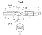
- FIG. 1 It is a top view which shows the medical device and the drive device which concerns on 1st Embodiment. It is sectional drawing which shows the proximal part of the medical device which concerns on 1st Embodiment. It is a figure which shows the vicinity of the connection part of the medical device which concerns on 1st Embodiment partially transparently, (A) is a plan view, (B) is a sectional view along line AA of (A), ( C) is a cross-sectional view taken along the line BB of (A). It is sectional drawing which shows the distal part of the medical device which concerns on 1st Embodiment.
- (A) is a plan view
- (B) is a sectional view along line CC of (A). .. It is a top view which shows the vicinity of the connection part of the medical device which concerns on 3rd Embodiment partially transparently.
- the medical device 10 according to the first embodiment is used for a procedure of being inserted into a blood vessel and destroying and removing an object such as a thrombus, plaque, atheroma, or calcified lesion in acute lower limb ischemia or deep vein thrombosis. ..
- an object such as a thrombus, plaque, atheroma, or calcified lesion in acute lower limb ischemia or deep vein thrombosis. ..
- the side of the device to be inserted into the blood vessel is referred to as the "distal side”
- the hand side to be operated is referred to as the "proximal side”.
- the object to be removed is not necessarily limited to thrombus, plaque, atheroma, and calcified lesion, and any object that may exist in the living lumen can be applicable.
- the medical device 10 is driven by being connected to a drive device 200 that generates a driving force and a suction force.
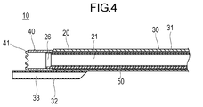
- the medical device 10 includes a long drive shaft 20 that is rotationally driven, an outer tube 30 that houses the drive shaft 20, and a cutting portion 40 that cuts an object.
- the medical device 10 further includes an inner tube 50 arranged inside the drive shaft 20, a proximal shaft 90 arranged on the proximal side of the drive shaft 20, and a connection connecting the proximal shaft 90 to the drive shaft 20. It is provided with a unit 100.
- the medical device 10 further includes a housing 60 that rotatably holds the proximal portion of the drive shaft 20, and a rotary input unit 110 that receives a rotational force from the drive device 200.
- the drive shaft 20 transmits the rotational force to the cutting portion 40.
- the drive shaft 20 is formed with a suction lumen 21 (chamber) for moving the cut object to the proximal side.
- the drive shaft 20 includes a long drive shaft main body 22 and an auxiliary member 23 fixed to a proximal portion of the drive shaft main body 22.
- the drive shaft 20 penetrates the outer pipe 30, and the cutting portion 40 is fixed to the distal portion.
- the proximal portion of the drive shaft 20 is located inside the housing 60.
- the drive shaft 20 is connected to the proximal shaft 90 via the connecting portion 100.
- the drive shaft 20 has a distal opening 26 at the distal end through which the suction lumen 21 opens.
- the distal opening 26 is an inlet for debris, which is a suction object formed by cutting.
- the drive shaft 20 has a proximal opening 25 at the proximal end.
- the proximal opening 25 is an outlet from which the debris that has entered the inside of the drive shaft 20 is discharged from the distal opening 26.
- the proximal opening 25 opens toward the proximal side.
- the drive shaft body 22 is flexible and has a characteristic of being able to transmit the rotational power acting from the proximal side to the distal side.
- the drive shaft body 22 is rotatably supported inside the housing 60 by a first bearing 67, which will be described later. Therefore, the drive shaft main body 22 can rotate smoothly at high speed.
- the auxiliary member 23 has a circular tube shape, and the proximal portion of the drive shaft main body 22 is inserted through the opening on the distal side. Further, in the auxiliary member 23, the connecting portion 100 is inserted through the opening on the proximal side.
- the inner diameter of the auxiliary member 23 substantially coincides with the outer diameter of the drive shaft main body 22. Therefore, the drive shaft main body 22 is fitted inside the auxiliary member 23. Therefore, the drive shaft main body 22 and the auxiliary member 23 are stably connected.
- the proximal end face 27 of the auxiliary member 23 is the proximal end face of the drive shaft 20 and has a ring shape.
- the proximal end surface 27 of the auxiliary member 23 is the most proximal side of the auxiliary member 23 facing the axial direction.
- the drive shaft main body 22 may be connected to the connecting portion 100 without the intervention of the auxiliary member 23. That is, the drive shaft 20 is composed of the drive shaft main body 22 and does not have to have the auxiliary member 23.
- the proximal shaft 90 has a rotational input unit 110 fixed to the proximal portion to receive a rotational force from the drive device 200.
- the proximal portion of the proximal shaft 90 projects proximally from the housing 60.
- the proximal shaft 90 is rotatably supported inside the housing 60 by a second bearing 68, which will be described later. Therefore, the proximal shaft 90 can rotate smoothly at high speed.
- the connecting portion 100 is a member that connects the drive shaft 20 on the distal side and the proximal shaft 90 on the proximal side.
- the connection portion 100 is connected to the drive shaft 20 without blocking the proximal opening 25 of the drive shaft 20 that opens toward the proximal side. Then, the connecting portion 100 extends from the connected drive shaft 20 to the proximal side.
- the connecting portion 100 is formed integrally with the proximal shaft 90, but may be formed separately from the proximal shaft 90.
- the connecting portion 100 has a substantially cylindrical shape, and one spiral groove 101 is formed on the outer peripheral surface.
- the connection portion 100 includes a spiral proximal portion 104 having a large outer diameter located on the proximal side and a spiral distal portion located on the distal side of the spiral proximal portion 104 and having an outer diameter smaller than that of the spiral proximal portion 104. It is equipped with 105.
- a step portion 106 whose outer diameter changes stepwise is formed between the spiral distal portion 105 and the spiral proximal portion 104. The step portion 106 comes into contact with the proximal end surface 27 of the drive shaft 20.
- the shape of the end surface of the stepped portion 106 of the connecting portion 100 that comes into contact with the proximal end surface 27 of the drive shaft 20 is different from that of the proximal end surface 27 of the drive shaft 20.
- the cross-sectional shape of the connecting portion 100 on the surface of the drive shaft 20 where the proximal end face 27 is located is different from the shape of the proximal end face 27. Therefore, the connecting portion 100 can be fixed to the proximal portion of the drive shaft 20 without blocking the axial opening of the proximal opening 25 of the drive shaft 20.
- the surface on which the proximal end surface 27 of the drive shaft 20 is located is preferably a flat surface, but it does not have to be a flat surface, and may be, for example, a curved surface or a bent surface.
- the connecting portion 100 may be formed with a constant outer diameter without being divided into the spiral proximal portion 104 and the spiral distal portion 105.
- the connecting portion 100 may be formed with an outer diameter capable of entering the proximal opening 25 without providing the step portion 106. In this case, the connecting portion 100 enters the proximal opening 25 and is fixed to the drive shaft 20 without providing the step portion 106 (end face) that abuts on the proximal end face 27.
- the distal end face 107 of the spiral distal portion 105 abuts on the proximal end face 28 of the drive shaft body 22 inside the auxiliary member 23.
- the distal end face 107 of the spiral distal portion 105 and the proximal end face 28 of the drive shaft body 22 do not have to abut each other.
- the outer diameter of the proximal spiral portion 104 is substantially the same as the outer diameter of the auxiliary member 23, but it does not have to be the same.
- the outer diameter of the distal spiral portion 105 substantially coincides with the inner diameter of the auxiliary member 23. Therefore, the distal spiral portion 105 fits into the lumen of the auxiliary member 23, and the distal spiral portion 105 is stably connected to the auxiliary member 23.
- the step portion 106 is in contact with the proximal end surface 27 of the auxiliary member 23. As a result, the connecting portion 100 and the auxiliary member 23 are stably connected in the axial direction.
- the connecting portion 100 is formed separately from the auxiliary member 23, it may be integrally formed.
- the auxiliary member 23, which is a part of the drive shaft 20, may be integrally formed with the connecting portion 100.
- the cylindrical shape provided with the proximal opening 25 can be specified as the auxiliary member 23. That is, the drive shaft 20 extends to the proximal end of the portion where the inner wall surface is formed over 360 degrees and surrounds the internal space all around.
- the proximal opening 25 opens axially from the proximal end of the portion where the inner wall surface is formed over 360 degrees. Therefore, the proximal surface 28 of the auxiliary member 23 may be located inside the integrally formed member.
- the proximal end face of the drive shaft 20 is the proximal end face 28 of the drive shaft main body 22, and has a ring shape.
- the cross-sectional shape of the connecting portion 100 (the shape of the distal end face 107) on the surface of the drive shaft body 22 where the proximal end face 28 is located is different from the shape of the proximal end face 28.
- the spiral groove 101 is formed on the outer peripheral surface of the connecting portion 100 by drawing a spiral from the distal end surface 107 of the connecting portion 100 toward the proximal side.
- the spiral groove 101 communicates with the suction lumen 21 of the drive shaft 20 at the distal end surface 107 of the connecting portion 100.
- the spiral groove 101 does not have to be formed up to the proximal end face of the connecting portion 100, but may be formed up to the proximal end face.
- the spiral direction of the spiral groove 101 is a direction in which an object inside the spiral groove 101 receives a force toward the proximal side when the connection portion 100 is rotated by a rotational force transmitted from the drive device 200.
- the winding direction of the spiral groove 101 of the connecting portion 100 is clockwise toward the distal side.
- the winding direction of the spiral groove 101 of the connecting portion 100 is counterclockwise toward the distal side.
- the depth H of the spiral groove 101 from the outer peripheral surface of the connecting portion 100 toward the central axis X is not particularly limited, but is larger than, for example, the distance R from the outer peripheral surface of the connecting portion 100 to the central axis X.
- the central passage P extending linearly along the central axis X of the connecting portion 100 (see the two-point chain line in FIG. 3). Is formed. That is, a central passage P surrounding the central axis X is formed at the center of the connecting portion 100, and the material of the connecting portion 100 does not exist on the central axis X. Therefore, the suction lumen 21 of the drive shaft 20 and the central passage P of the connecting portion 100 are linearly communicated with each other along the central axis X.
- the depth H of the spiral groove 101 may be equal to or less than the distance R of the connecting portion 100.
- the spiral angle ⁇ of the spiral groove 101 with respect to the central axis X is not particularly limited, but is, for example, 1 to 89 °, preferably 10 to 60 °, and more preferably 20 to 50 °. If the angle ⁇ is too close to 90 °, it becomes difficult for debris to pass through the spiral groove 101. If the angle ⁇ is too close to 0 °, the rotating spiral groove 101 weakens the force for transporting debris to the proximal side.
- the angle ⁇ of the spiral may change along the central axis X of the connecting portion 100. For example, the angle ⁇ of the spiral may be closer to 0 ° on the distal side of the connection portion 100 and closer to 90 ° toward the proximal side. As a result, the spiral groove 101 can smoothly move the debris.
- the constituent material of the drive shaft main body 22 is not particularly limited, but for example, polyolefins such as stainless steel, Ta, Ti, Pt, Au, W, polyethylene and polypropylene, polyamides, polyesters such as polyethylene terephthalate, and fluoropolymers such as ETFE.
- PEEK polyetheretherketone
- polyimide polyimide
- it may be composed of a plurality of materials, and a reinforcing member such as a wire rod may be embedded.
- the constituent materials of the auxiliary member 23, the connecting portion 100, and the proximal shaft 90 are not particularly limited, but for example, stainless steel, Ta, Ti, Pt, Au, W, shape memory alloy, and the like can be preferably used.
- the constituent materials of the auxiliary member 23, the connecting portion 100, and the proximal shaft 90 may be a resin such as an engineering plastic such as polyetheretherketone (PEEK).
- the rotation input unit 110 is a substantially columnar member fixed to the proximal end of the drive shaft 20.
- the rotation input unit 110 is a member that is connected to the rotation drive shaft 221 of the drive device 200 to receive rotational power.
- the proximal portion of the rotation input portion 110 is provided with a fitting recess 111 into which the rotation drive shaft 221 is fitted.
- the inner pipe 50 is a flexible pipe body and is arranged inside the drive shaft 20.
- the inner pipe 50 suppresses damage to the inner peripheral surface of the drive shaft 20 due to debris flowing inside the drive shaft 20.
- the inner pipe 50 may or may not be fixed to the inner peripheral surface of the drive shaft 20.
- the radius R1 of the outer peripheral surface of the inner pipe 50 is larger than the distance D from the central axis X to the nearest portion of the connecting portion 100 on the distal end surface 107 of the connecting portion 100. Further, the distance D is larger than the radius R2 of the inner peripheral surface of the drive shaft main body 22.
- a part of the distal end surface 107 of the connecting portion 100 is located radially inside the inner peripheral surface of the drive shaft main body 22. Therefore, when the inner tube 50 moves proximally inside the suction lumen 21, the proximal end face of the inner tube 50 comes into contact with the distal end face 107 of the connecting portion 100. Therefore, the inner pipe 50 is prevented from entering the spiral groove 101 of the connecting portion 100.
- the inner pipe 50 does not have to be provided.
- the outer tube 30 includes an outer tube main body 31 that rotatably accommodates the drive shaft 20 and a distal tube 32 fixed to the side surface of the distal portion of the outer tube main body 31. It has.
- the outer pipe body 31 is a flexible pipe body, and the proximal portion is fixed to the housing 60.
- the distal portion of the outer tube body 31 is located on the proximal side of the cutting portion 40.
- the distal tube 32 is a flexible tubular body and is fixed to the outer peripheral surface of the distal portion of the outer tube body 31.
- the distal tube 32 has a guide wire lumen 33 into which a guide wire can be inserted.
- the cutting portion 40 is a member that cuts and reduces an object such as a thrombus, plaque, or calcified lesion. Therefore, "cutting" means applying a force to an object in contact to make the object smaller.
- the method of applying force in cutting and the shape and shape of the object after cutting are not limited.
- the cutting portion 40 has the strength to cut the above-mentioned object.
- the cutting portion 40 is fixed to the outer peripheral surface of the distal portion of the drive shaft 20.
- the proximal end face of the cutting portion 40 may be fixed to the distal end face of the drive shaft 20.
- the cutting portion 40 is a cylinder that projects distally to the drive shaft 20.
- the distal end of the cutting portion 40 is provided with a sharp blade 41.
- the shape of the blade 41 is not particularly limited.
- the cutting portion 40 may have a large number of minute abrasive grains instead of the blade 41.
- the housing 60 has a first portion 61 arranged on the distal side, a second portion 62 arranged substantially in the center, and a third portion arranged on the proximal side. It includes a portion 63.
- the first site 61 is connected to the distal portion of the second site 62.
- a first sealing portion 64 that seals the internal space is arranged between the first portion 61 and the second portion 62.
- the first portion 61 is formed with a first internal space 65 through which the drive shaft 20 rotatably penetrates.
- the proximal portion of the outer tube main body 31 is fixed to the inner peripheral surface on the distal side of the first internal space 65.
- the second part 62 is located on the proximal side of the first part 61.
- the second portion 62 is formed with a second internal space 66 through which the drive shaft 20, the connecting portion 100, and the proximal shaft 90 rotatably penetrate.
- the second portion 62 has a discharge port 69 to which the suction tube 231 of the drive device 200 described later can be connected.
- the flow path of the discharge port 69 communicates with the second internal space 66.
- a first bearing 67 and a second bearing 68 are arranged on the inner peripheral surface of the second internal space 66.
- the inner peripheral surface of the first bearing 67 is in contact with the outer peripheral surface of the proximal portion of the drive shaft 20.
- the inner peripheral surface of the second bearing 68 is in contact with the outer peripheral surface of the distal portion of the proximal shaft 90. Therefore, the drive shaft 20, the connection portion 100, and the proximal shaft 90 are rotatably supported by the first bearing 67 and the second bearing 68, and can rotate smoothly at high speed.
- the position where the first bearing 67 and the second bearing 68 are arranged is not limited.
- the first bearing 67 and / or the second bearing 68 may be fixed to the outer peripheral surface of the connection portion 100. Further, the first bearing 67 and / or the second bearing 68 may not be provided.
- the third part 63 is connected to the proximal part of the second part 62.
- the third portion 63 is formed with a third internal space 71 through which the proximal shaft 90 rotatably penetrates.
- a second sealing portion 70 that seals the second internal space 66 is arranged between the second portion 62 and the third portion 63. Further, the second sealing portion 70 contacts the outer peripheral surface of the proximal shaft 90 and seals between the second portion 62 and the proximal shaft 90.
- the proximal opening 25 of the drive shaft 20 is located in the second internal space 66. Therefore, the negative pressure acting on the discharge port 69 from the suction tube 231 acts on the inside of the drive shaft 20 from the proximal opening 25.
- the first seal portion 64 and the second seal portion 70 suppress the negative pressure of the first internal space 65 and the second internal space 66 from escaping.
- at least a part of the confluence portion 72 in which the flow path of the discharge port 69 is connected to the second internal space 66 is the range S in which the spiral groove 101 exists in the axial direction of the connection portion 100. It is preferable to be in.
- the merging portion 72 is a portion of the inner surface forming the flow path of the discharge port 69, which is connected to the inner surface forming the second internal space 66.
- the confluence 72 is preferably close to the proximal opening 25.
- the merging portion 72 may partially overlap the proximal opening 25 in the axial direction of the connecting portion 100. Further, it is preferable that at least a part of the merging portion 72 is on the proximal side of the proximal opening 25 of the drive shaft 20 in the axial direction of the connecting portion 100.
- the position of the merging portion 72 is not limited to the above range. Further, the position of the proximal opening 25 of the drive shaft 20 is not particularly limited as long as a negative pressure from the discharge port 69 can act.
- the drive device 200 includes a drive unit 220 that generates a rotational force and a suction unit 230 that generates a suction force.
- the drive unit 220 includes a rotation drive shaft 221 and a first motor 222 that rotates the rotation drive shaft 221.
- the rotation speed of the first motor 222 is not particularly limited, but is, for example, 5,000 to 200,000 rpm.
- the suction unit 230 includes a suction tube 231, a pump 232, a second motor 233, and a waste liquid pack 235.
- the suction tube 231 can be connected to the discharge port 69 of the medical device 10.
- the pump 232 is driven by a second motor 233 to exert a negative pressure on the suction tube 231. Further, the pump 232 discharges the fluid sucked through the suction tube 231 to the waste liquid pack 235.
- the configuration of the drive device 200 is not limited to the above example.
- the mechanism for generating the rotational force and the mechanism for generating the suction force may be separate devices.
- the surgeon inserts a guide wire (not shown) into the blood vessel to reach the vicinity of the lesion.
- the surgeon then inserts the proximal end of the guidewire into the guidewire lumen 33 of the medical device 10. After that, the medical device 10 is brought into the vicinity of the lesion using the guide wire as a guide.
- the operator connects the rotation drive shaft 121 of the drive device 200 to the rotation input unit 110. Subsequently, the operator connects the suction tube 231 to the discharge port 69. After this, the operator activates the drive device 200. As a result, the rotation of the rotation drive shaft 121 and the suction of the suction tube 231 are started.
- the rotation drive shaft 121 rotates the rotation input unit 110.
- the proximal shaft 90 fixed to the rotation input portion 110 rotates, and the connecting portion 100, the drive shaft 20, and the cutting portion 40 rotate together with the proximal shaft 90.
- the rotating cutting portion 40 cuts the lesion portion in the blood vessel.
- the suction tube 231 exerts a negative pressure on the second internal space 66 via the discharge port 69. Therefore, a negative pressure acts on the suction lumen 21 of the drive shaft 20 from the proximal opening 25 located in the second internal space 66. Therefore, as shown in FIG. 4, the lesion portion cut by the blade 41 of the cutting portion 40 becomes debris and moves inside the cutting portion 40 toward the proximal end side. Debris is sucked into the suction lumen 21 through the distal opening 26 of the drive shaft 20.
- the sucked debris passes through the proximal end of the drive shaft body 22 and reaches the spiral groove 101 of the spiral distal portion 105 inside the auxiliary member 23 as shown in FIGS.
- the debris inside the spiral groove 101 is pushed toward the proximal side by receiving a force toward the proximal side from the wall surface of the rotating spiral groove 101. Therefore, a part of the debris smoothly moves to the proximal side in the spiral groove 101 of the distal spiral portion 105, and moves to the spiral groove 101 of the helical proximal portion 104. Further, a part of the debris may be discharged directly from the proximal opening 25 which opens to the proximal side to the second internal space 66 without passing through the spiral groove 101 of the spiral proximal portion 104.
- the spiral groove 101 of the helical proximal portion 104 is not covered with the auxiliary member 23. Therefore, the spiral groove 101 of the helical proximal portion 104 is not covered with the auxiliary member 23 and is open to the outside in the radial direction.
- the debris that has moved to the spiral groove 101 of the helical proximal portion 104 moves from the spiral groove 101 to the radial outer side of the spiral proximal portion 104, and moves to the second internal space 66 that surrounds the connecting portion 100.
- the debris that has moved to the second internal space 66 surrounding the connecting portion 100 enters the flow path of the discharge port 69 through the merging portion 72 and is discharged to the suction tube 231.
- the merging portion 72 is in the range S where the spiral groove 101 exists in the axial direction of the connecting portion 100. Further, at least a part of the confluence 72 is located proximal to the proximal opening 25.
- the debris discharged from the proximal opening 25 and the spiral groove 101 to the second internal space 66 can be effectively moved to the discharge port 69 through the adjacent confluence 72. Therefore, the debris is less likely to stay in the second internal space 66, flows smoothly, and is discharged to the outside from the discharge port 69.
- a hollow central passage P surrounding the central axis X is formed at the center of the connecting portion 100. Therefore, the debris flowing through the suction lumen 21 can smoothly enter the spiral groove 101 of the connecting portion 100. As a result, the debris is less likely to be clogged in the spiral groove 101, flows smoothly, and is discharged to the outside from the discharge port 69. The discharged debris reaches the pump 232 through the suction tube 231. The debris that has reached the pump 232 is discharged to the waste liquid pack 235 as shown in FIG. After the lesion has been cut and the debris has been aspirated, the operator ceases operation of the drive device 200. As a result, the rotation of the drive shaft 20 is stopped, and the suction of the pump 232 is stopped. As a result, cutting by the cutting portion 40 and discharge of debris are stopped. After this, the medical device 10 is removed from the blood vessel to complete the procedure.
- the medical device 10 is a medical device 10 that removes an object in the biological lumen, and is a drive shaft 20 that is rotatable and has a lumen, and a drive shaft 20.
- a cutting portion 40 that is fixed to the distal portion of the body and cuts an object, a proximal shaft 90 that is arranged and rotatable proximal to the drive shaft 20, and a proximal shaft 90 and a drive shaft 20 are connected to each other.
- a connecting portion 100 capable of transmitting the rotational force of the proximal shaft to the drive shaft 20 and a housing 60 formed with a discharge port 69 for rotatably accommodating the connecting portion 100 and discharging a cut object to the outside.
- the drive shaft 20 has a proximal opening 25 on the proximal end face 27 that opens in the axial direction (direction along the central axis X) and discharges the cut object, and the proximal end face 27 is located.
- the cross-sectional shape of the connecting portion 100 on the surface is different from the shape of the proximal end surface 27. At least a part of the object emitted from the proximal opening 25 is emitted directly into the internal space of the housing 100 while moving in the axial direction without passing through the inside of the connecting portion 100.
- the medical device 10 configured as described above is a proximal portion in which debris, which is an object formed by being cut by a cutting portion 40 and flows proximally through the lumen of the drive shaft 20, opens in the axial direction. Since it is discharged through the opening 25, it is difficult to wind around the rotating connection 100.
- the opening (discharge port) on the proximal side of the drive shaft, which is a tubular body is a side hole penetrating the side wall surface of the tubular body, the debris discharged from the side hole winds around the rotating drive shaft. Cheap. Compared with this case, the medical device 10 can significantly reduce the wrapping of debris.
- the medical device 10 can suck the debris formed by cutting the lesion portion, suppress the retention of the debris in the device, and effectively discharge the debris.
- the connecting portion 100 has a shape different from that of the proximal portion of the drive shaft 20, the shape is such that the proximal shaft 90 and the drive shaft 20 are connected and debris is not easily discharged from the proximal opening 25.
- Cheap That is, since the connection portion 100 can be freely designed without depending on the shape of the drive shaft 20, the shape can be made suitable for the discharge of debris from the proximal opening 25.
- connection portion 100 is not cylindrical as a whole. Therefore, even if the connecting portion 100 has the proximal opening 25 and is connected to the cylindrical drive shaft 20, it is easy to maintain the state in which the proximal opening 25 opens in the axial direction. Since the connecting portion 100 does not form an internal space surrounded by a cylindrical shape, the object emitted from the proximal opening 25 in the axial direction does not enter the internal space of the connecting portion 100 and is directly inside the housing 100. Easy to be released into space.
- the connecting portion 100 comes into contact with the proximal end surface 27 of the drive shaft 20.
- the connecting portion 100 can be connected to the drive shaft 20 without entering the cavity of the drive shaft 20. Therefore, a wide cavity of the drive shaft 20 can be secured. Therefore, debris is likely to be satisfactorily released from the cavity of the drive shaft 20.
- the proximal end face of the drive shaft 20 may be the proximal end face 28 of the drive shaft body 22.
- the connecting portion 100 has a spiral groove 101 extending spirally on the outer peripheral surface.
- the spiral groove 101 of the rotating connection portion 100 can apply a force toward the proximal side to the internal debris to assist the movement of the debris toward the proximal side.
- the debris moves along the spiral groove 101 and receives a force from the spiral groove 101 to promote the release. Therefore, it is difficult for debris to wind around the rotating connection portion 100. Therefore, the medical device 10 can suppress the retention of debris in the proximal opening 25 by the spiral groove 101 and effectively discharge the debris.
- the connecting portion 100 having a spiral groove 101 extending spirally on the outer peripheral surface may be formed by twisting, for example, a substantially plate-shaped member.
- the connecting portion 100 can secure a wide continuous flow path from the lumen of the drive shaft 20 while assisting the movement of the debris toward the proximal side by the spiral groove 101. Therefore, the debris can smoothly flow through the spiral groove 101 of the connecting portion 100 without clogging. Therefore, debris tends to be satisfactorily discharged from the cavity of the drive shaft 20 and the spiral groove 101 of the connection portion 100.
- the drive shaft 20 is a tubular auxiliary member 23 that surrounds the drive shaft main body 22 extending from the cutting portion 40 to the proximal side, the outer peripheral surface of the proximal portion of the drive shaft main body 22, and the distal portion of the connection portion 100. And have. Thereby, the fixing force of the connecting portion 100 to the drive shaft main body 22 can be improved. Further, since the auxiliary member 23 is arranged so as to surround the drive shaft main body 22 and the connecting portion 100, a wide flow path through which debris flows can be secured. Therefore, debris is likely to be satisfactorily released from the cavity of the drive shaft 20.
- the drive shaft 20 In a cross section orthogonal to the axis (cross section orthogonal to the central axis X) at the portion where a part of the connecting portion 100 is inserted inside the drive shaft 20 and the connecting portion 100 of the drive shaft 20 is inserted, the drive shaft 20
- the flow path area is equal to or larger than the area occupied by the connecting portion 100.
- the medical device 10 according to the second embodiment differs from the first embodiment only in the structure of the connecting portion 120.
- the parts having the same functions as those in the first embodiment are designated by the same reference numerals, and the description thereof will be omitted.
- the connecting portion 120 includes two spiral grooves 121 and 122. Therefore, the portion of the connecting portion 120 where the spiral grooves 121 and 122 are formed has a twisted plate shape.
- the distal portion of the connecting portion 120 arranged inside the auxiliary member 23 is formed with a protruding portion 123 whose outer diameter gradually decreases toward the distal side on the central axis X of the connecting portion 120. That is, the connecting portion 120 has a protruding portion 123 at the distal portion, which protrudes toward the distal side and becomes thinner. As a result, the material constituting the connecting portion 120 is reduced toward the distal side, and inevitably, a wide passage through which debris can pass is secured.
- the medical device 10 can suppress the retention of debris formed by cutting the lesion portion and effectively discharge the debris.
- the most distal end of the protrusion 123 may or may not enter the suction lumen 21 of the drive shaft 20.
- the distal portion of the connecting portion 120 has a substantially plate shape, and both sides (bottom surfaces of the spiral grooves 121 and 122) arranged in the plate thickness direction of the connecting portion 120 are the central axis X of the drive shaft 20. Be placed. As a result, debris flowing proximally through the lumen of the drive shaft 20 flows along the surface of the rotating plate-shaped connecting portion 120, so that it is difficult to wind around the connecting portion 120.
- the medical device 10 according to the third embodiment differs from the first embodiment only in the structure of the connecting portion 130.
- the parts having the same functions as those in the first embodiment are designated by the same reference numerals, and the description thereof will be omitted.
- the connection portion 130 includes two spiral grooves 131 and 132 as in the second embodiment.
- the distal portion of the connecting portion 130 arranged inside the auxiliary member 23 is formed with a recess 133 recessed toward the proximal side.
- the connecting portion 130 has a recess 133 that is recessed toward the proximal side on the central axis X of the connecting portion 130.
- the material constituting the connecting portion 130 is reduced toward the distal side, and inevitably, a wide passage through which debris can pass is secured. Therefore, the debris flowing to the proximal side through the lumen of the drive shaft 20 easily passes through the recess 133. Therefore, the debris is unlikely to wrap around the rotating recess 133. Therefore, the medical device 10 can suppress the retention of debris formed by cutting the lesion portion and effectively discharge the debris.
- the most distal end of the connecting portion 130 may or may not come into contact with the proximal end surface 28 of the drive shaft body 22.
- the living lumen into which the medical device 10 is inserted is not limited to a blood vessel, and may be, for example, a vascular duct, a ureter, a bile duct, an oviduct, a hepatic duct, or the like.
- the medical device 10 and the drive device 200 may be integrally configured.
- the connecting portion 140 may have a flat plate shape.
- the connecting portion 150 may be a member having a cross-shaped cross section perpendicular to the axis. That is, the connecting portion 150 has a plurality of flat plate shapes.
- the connecting portion may be a member formed into a tubular shape by spirally winding one or two or more wire rods.
- the wire may be solid or hollow.
- the cutting portion may not be provided. Then, the object moving on the drive shaft may be cut by the rotation of the connecting portion.
- the suction force may be generated by the drive shaft or the connection portion instead of the suction portion 230 connected to the discharge port 69.
- the drive shaft and / or connection can generate suction by rotating if it has the structure of an Archimedes' screw pump.
- the discharge port 69 can discharge the debris even if it is not connected to the suction unit 230 that generates the suction force.
Abstract
Provided is a medical device which sucks an object in a biological lumen and is capable of preventing the object from being retained inside the device and effectively discharging the object. The medical device (10) is for removing an object within a biological lumen and has: a rotatable drive shaft (20) having a lumen; a cutting unit (40) that is fixed to a distal section of the drive shaft (20) and cuts an object; a rotatable proximal shaft (90) disposed proximal to the drive shaft (20); a connection unit (100) connecting the proximal shaft (90) and the drive shaft (20) and capable of transmitting the rotary force of the proximal shaft (90) to the drive shaft (20); and a housing (60) in which the connection unit (100) is rotatably accommodated and a discharge port (69) for discharging the cut object to the outside is formed. The drive shaft (20) has, on a proximal end face (27), a proximal opening (25) which opens in the axial direction and through which the cut object is released. The cross-sectional shape of the connection unit (100) at the plane where the proximal end face (27) is located is different from the shape of the proximal end face (27).
Description
本発明は、生体管腔の物体を除去するための医療デバイスに関する。
The present invention relates to a medical device for removing an object in a biological lumen.
血管内のプラークや血栓などによる狭窄部の治療方法は、バルーンにより血管を拡張する方法や、網目状またはコイル状のステントを血管の支えとして血管内に留置する方法などが挙げられる。しかしながら、これらの方法は、石灰化により硬くなっている狭窄部や、血管の分岐部で生じている狭窄部を治療することは、困難である。このような場合においても治療が可能な方法として、プラークや血栓などの狭窄物を切削して除去する方法がある。
Examples of treatment methods for stenosis caused by plaque or thrombus in a blood vessel include a method of dilating the blood vessel with a balloon and a method of placing a mesh-like or coiled stent in the blood vessel as a support for the blood vessel. However, it is difficult for these methods to treat a stenosis that is hardened by calcification or a stenosis that occurs at a bifurcation of a blood vessel. As a method capable of treating such a case, there is a method of cutting and removing a stenosis such as a plaque or a thrombus.
例えば特許文献1には、物体を切削する作動ヘッドが、駆動シャフトの遠位部に固定されたデバイスが記載されている。このデバイスは、駆動シャフトを回転させて、作動ヘッドにより物体を切削できる。このデバイスは、手元に、吸引力を作用させる排出ポートを備えたハウジングを備えている。切削して形成されたデブリは、駆動シャフトの遠位開口部から内腔に吸引され、近位側へ移動される。この後、デブリは、駆動シャフトの近位開口部からハウジング内に移動し、排出ポートから排出される。
For example, Patent Document 1 describes a device in which an operating head for cutting an object is fixed to a distal portion of a drive shaft. The device can rotate the drive shaft and cut an object with an actuating head. The device has a housing at hand with a discharge port that acts as a suction force. The debris formed by cutting is sucked into the lumen through the distal opening of the drive shaft and moved to the proximal side. After this, the debris moves into the housing through the proximal opening of the drive shaft and is discharged from the discharge port.
デブリは、ハウジング内で、回転している駆動シャフトの外周に巻き付きやすい。デブリが、駆動シャフトの近位側の開口部を塞ぐと、デブリはハウジング内に滞留し、排出ポートから外部へ排出され難い。
Debris easily wraps around the outer circumference of the rotating drive shaft inside the housing. When the debris closes the opening on the proximal side of the drive shaft, the debris stays in the housing and is difficult to be discharged from the discharge port to the outside.
本発明は、上述した課題を解決するためになされたものであり、生体管腔の物体を吸引して、物体のデバイス内での滞留を抑制し、物体を効果的に排出できる医療デバイスを提供することを目的とする。
The present invention has been made to solve the above-mentioned problems, and provides a medical device capable of sucking an object in a biological lumen, suppressing the retention of the object in the device, and effectively discharging the object. The purpose is to do.
上記目的を達成する本発明に係る医療デバイスの一態様は、生体管腔内の物体を除去する医療デバイスであって、回転可能であって内腔を有する駆動シャフトと、前記駆動シャフトの遠位部に固定されて物体を切削する切削部と、前記駆動シャフトよりも近位側に配置されて回転可能な近位シャフトと、前記近位シャフトおよび前記駆動シャフトを接続して前記近位シャフトの回転力を前記駆動シャフトへ伝達可能な接続部と、前記接続部を回転可能に収容し、切削された前記物体を外部へ排出する排出ポートが形成されたハウジングと、を有し、前記駆動シャフトは、軸方向に開口し、切削された前記物体を放出する近位開口部を近位端面に有し、前記近位端面が位置する面における前記接続部の断面形状は、前記近位端面の形状と異なる。
One aspect of the medical device according to the present invention that achieves the above object is a medical device that removes an object in a biological lumen, a drive shaft that is rotatable and has a lumen, and a distal drive shaft. A cutting portion that is fixed to a portion to cut an object, a proximal shaft that is arranged and rotatable on the proximal side of the drive shaft, and the proximal shaft and the drive shaft are connected to form the proximal shaft. The drive shaft has a connection portion capable of transmitting a rotational force to the drive shaft, and a housing formed with a discharge port that rotatably accommodates the connection portion and discharges the cut object to the outside. Has a proximal opening on the proximal end face that opens axially and discharges the cut object, and the cross-sectional shape of the connection on the surface where the proximal end face is located is the proximal end face. Different from the shape.
上記目的を達成する本発明に係る医療デバイスの他の態様は、生体管腔の物体を除去する医療デバイスであって、回転可能であって内腔を有する駆動シャフトと、前記駆動シャフトよりも近位側に配置されて回転可能な近位シャフトと、前記近位シャフトおよび前記駆動シャフトを接続して前記近位シャフトの回転力を前記駆動シャフトへ伝達可能な接続部と、前記接続部を回転可能に収容し、前記物体を外部へ排出する排出ポートが形成されたハウジングと、を有し、前記駆動シャフトは、軸方向に開口し、切削された前記物体を放出する近位開口部を近位端面に有し、前記近位端面が位置する面における前記接続部の断面形状は、前記近位端面の形状と異なる。
Another aspect of the medical device according to the present invention that achieves the above object is a medical device that removes an object in a biological lumen, which is closer to a drive shaft that is rotatable and has a lumen and is closer than the drive shaft. A proximal shaft that is arranged on the position side and can rotate, a connecting portion that connects the proximal shaft and the driving shaft and can transmit the rotational force of the proximal shaft to the driving shaft, and the connecting portion that rotates. It has a housing in which a discharge port is formed to accommodate and discharge the object to the outside, and the drive shaft is axially open and close to a proximal opening to discharge the machined object. The cross-sectional shape of the connecting portion on the surface having the position end face and where the proximal end face is located is different from the shape of the proximal end face.
上記のように構成した医療デバイスは、駆動シャフトの内腔を近位側へ流れる物体が、回転する接続部に巻き付き難い。このため、駆動シャフトの近位側の開口部が物体によって完全に塞がれることは抑制される。したがって、医療デバイスは、生体管腔の物体を吸引して、物体のデバイス内での滞留を抑制し、物体を効果的に排出できる。
In the medical device configured as described above, it is difficult for an object flowing proximally in the lumen of the drive shaft to wrap around the rotating connection part. Therefore, it is suppressed that the opening on the proximal side of the drive shaft is completely blocked by the object. Therefore, the medical device can suck the object in the biological lumen, suppress the retention of the object in the device, and effectively discharge the object.
以下、図面を参照して、本発明の実施の形態を説明する。なお、図面における各部材の大きさや比率は、説明の都合上誇張され実際の大きさや比率とは異なる場合がある。
Hereinafter, embodiments of the present invention will be described with reference to the drawings. The size and ratio of each member in the drawings may be exaggerated for convenience of explanation and may differ from the actual size and ratio.
<第1実施形態>
第1実施形態に係る医療デバイス10は、急性下肢虚血や深部静脈血栓症において、血管内に挿入され、血栓、プラーク、アテローム、石灰化病変等の物体を破壊して除去する処置に用いられる。本明細書では、デバイスの血管に挿入する側を「遠位側」、操作する手元側を「近位側」と称することとする。なお、除去する物体は、必ずしも血栓、プラーク、アテローム、石灰化病変に限定されず、生体管腔内に存在し得る物体は、全て該当し得る。 <First Embodiment>
Themedical device 10 according to the first embodiment is used for a procedure of being inserted into a blood vessel and destroying and removing an object such as a thrombus, plaque, atheroma, or calcified lesion in acute lower limb ischemia or deep vein thrombosis. .. In the present specification, the side of the device to be inserted into the blood vessel is referred to as the "distal side", and the hand side to be operated is referred to as the "proximal side". The object to be removed is not necessarily limited to thrombus, plaque, atheroma, and calcified lesion, and any object that may exist in the living lumen can be applicable.
第1実施形態に係る医療デバイス10は、急性下肢虚血や深部静脈血栓症において、血管内に挿入され、血栓、プラーク、アテローム、石灰化病変等の物体を破壊して除去する処置に用いられる。本明細書では、デバイスの血管に挿入する側を「遠位側」、操作する手元側を「近位側」と称することとする。なお、除去する物体は、必ずしも血栓、プラーク、アテローム、石灰化病変に限定されず、生体管腔内に存在し得る物体は、全て該当し得る。 <First Embodiment>
The
医療デバイス10は、図1、2に示すように、駆動力および吸引力を発生させる駆動デバイス200に連結されて駆動される。医療デバイス10は、長尺であって回転駆動される駆動シャフト20と、駆動シャフト20を収容する外管30と、物体を切削する切削部40とを備えている。医療デバイス10は、さらに、駆動シャフト20の内部に配置される内管50と、駆動シャフト20の近位側に配置される近位シャフト90と、近位シャフト90を駆動シャフト20に接続する接続部100とを備えている。医療デバイス10は、さらに、駆動シャフト20の近位部を回転可能に保持するハウジング60と、駆動デバイス200から回転力を受ける回転入力部110とを備えている。
As shown in FIGS. 1 and 2, the medical device 10 is driven by being connected to a drive device 200 that generates a driving force and a suction force. The medical device 10 includes a long drive shaft 20 that is rotationally driven, an outer tube 30 that houses the drive shaft 20, and a cutting portion 40 that cuts an object. The medical device 10 further includes an inner tube 50 arranged inside the drive shaft 20, a proximal shaft 90 arranged on the proximal side of the drive shaft 20, and a connection connecting the proximal shaft 90 to the drive shaft 20. It is provided with a unit 100. The medical device 10 further includes a housing 60 that rotatably holds the proximal portion of the drive shaft 20, and a rotary input unit 110 that receives a rotational force from the drive device 200.
駆動シャフト20は、回転力を切削部40に伝達する。駆動シャフト20は、切削した物体を近位側へ移動させるための吸引ルーメン21(内腔)が形成されている。駆動シャフト20は、長尺な駆動シャフト本体22と、駆動シャフト本体22の近位部に固定される補助部材23とを備えている。駆動シャフト20は、外管30を貫通し、遠位部に切削部40が固定されている。駆動シャフト20の近位部は、ハウジング60の内部に位置している。駆動シャフト20は、接続部100を介して、近位シャフト90に連結される。駆動シャフト20は、遠位端に、吸引ルーメン21が開口する遠位開口部26を有している。遠位開口部26は、切削して形成される吸引対象物であるデブリが入り込む入口である。駆動シャフト20は、近位端に、近位開口部25を有している。近位開口部25は、遠位開口部26から駆動シャフト20の内部に入ったデブリが放出される出口である。近位開口部25は、近位側へ向かって開口している。
The drive shaft 20 transmits the rotational force to the cutting portion 40. The drive shaft 20 is formed with a suction lumen 21 (chamber) for moving the cut object to the proximal side. The drive shaft 20 includes a long drive shaft main body 22 and an auxiliary member 23 fixed to a proximal portion of the drive shaft main body 22. The drive shaft 20 penetrates the outer pipe 30, and the cutting portion 40 is fixed to the distal portion. The proximal portion of the drive shaft 20 is located inside the housing 60. The drive shaft 20 is connected to the proximal shaft 90 via the connecting portion 100. The drive shaft 20 has a distal opening 26 at the distal end through which the suction lumen 21 opens. The distal opening 26 is an inlet for debris, which is a suction object formed by cutting. The drive shaft 20 has a proximal opening 25 at the proximal end. The proximal opening 25 is an outlet from which the debris that has entered the inside of the drive shaft 20 is discharged from the distal opening 26. The proximal opening 25 opens toward the proximal side.
駆動シャフト本体22は、柔軟で、かつ近位側から作用する回転の動力を遠位側に伝達可能な特性を有する。駆動シャフト本体22は、ハウジング60の内部で、後述する第1の軸受67により回転可能に支持される。このため、駆動シャフト本体22は、高速で滑らかに回転可能である。
The drive shaft body 22 is flexible and has a characteristic of being able to transmit the rotational power acting from the proximal side to the distal side. The drive shaft body 22 is rotatably supported inside the housing 60 by a first bearing 67, which will be described later. Therefore, the drive shaft main body 22 can rotate smoothly at high speed.
補助部材23は、円管形状であり、遠位側の開口から駆動シャフト本体22の近位部が挿入されている。さらに、補助部材23は、近位側の開口から接続部100が挿入されている。補助部材23の内径は、駆動シャフト本体22の外径と略一致する。このため、駆動シャフト本体22が補助部材23の内部に嵌合する。したがって、駆動シャフト本体22および補助部材23は、安定して連結される。補助部材23の近位端面27は、駆動シャフト20の近位端面であり、リング形状である。補助部材23の近位端面27は、補助部材23の最も近位側で軸方向を向く面である。なお、駆動シャフト本体22は、補助部材23を介さずに接続部100に連結されてもよい。すなわち、駆動シャフト20は、駆動シャフト本体22により構成されて、補助部材23を有さなくてもよい。
The auxiliary member 23 has a circular tube shape, and the proximal portion of the drive shaft main body 22 is inserted through the opening on the distal side. Further, in the auxiliary member 23, the connecting portion 100 is inserted through the opening on the proximal side. The inner diameter of the auxiliary member 23 substantially coincides with the outer diameter of the drive shaft main body 22. Therefore, the drive shaft main body 22 is fitted inside the auxiliary member 23. Therefore, the drive shaft main body 22 and the auxiliary member 23 are stably connected. The proximal end face 27 of the auxiliary member 23 is the proximal end face of the drive shaft 20 and has a ring shape. The proximal end surface 27 of the auxiliary member 23 is the most proximal side of the auxiliary member 23 facing the axial direction. The drive shaft main body 22 may be connected to the connecting portion 100 without the intervention of the auxiliary member 23. That is, the drive shaft 20 is composed of the drive shaft main body 22 and does not have to have the auxiliary member 23.
近位シャフト90は、近位部に、駆動デバイス200から回転力を受ける回転入力部110が固定されている。近位シャフト90の近位部は、ハウジング60から近位側へ突出している。近位シャフト90は、ハウジング60の内部で、後述する第2の軸受68により回転可能に支持される。このため、近位シャフト90は、高速で滑らかに回転可能である。
The proximal shaft 90 has a rotational input unit 110 fixed to the proximal portion to receive a rotational force from the drive device 200. The proximal portion of the proximal shaft 90 projects proximally from the housing 60. The proximal shaft 90 is rotatably supported inside the housing 60 by a second bearing 68, which will be described later. Therefore, the proximal shaft 90 can rotate smoothly at high speed.
接続部100は、図2、3に示すように、遠位側の駆動シャフト20と、近位側の近位シャフト90とを連結する部材である。接続部100は、近位側へ向かって開口する駆動シャフト20の近位開口部25を塞がずに駆動シャフト20に接続される。そして、接続部100は、接続される駆動シャフト20から近位側へ延在する。なお、本実施形態において、接続部100は、近位シャフト90と一体的に形成されているが、近位シャフト90と別体で形成されてもよい。
As shown in FIGS. 2 and 3, the connecting portion 100 is a member that connects the drive shaft 20 on the distal side and the proximal shaft 90 on the proximal side. The connection portion 100 is connected to the drive shaft 20 without blocking the proximal opening 25 of the drive shaft 20 that opens toward the proximal side. Then, the connecting portion 100 extends from the connected drive shaft 20 to the proximal side. In the present embodiment, the connecting portion 100 is formed integrally with the proximal shaft 90, but may be formed separately from the proximal shaft 90.
接続部100は、略円柱形状であり、外周面に1つの螺旋溝101が形成されている。接続部100は、近位側に位置する外径の大きい螺旋近位部104と、螺旋近位部104の遠位側に位置して螺旋近位部104よりも外径の小さい螺旋遠位部105とを備えている。螺旋遠位部105と螺旋近位部104との間には、外径が段差的に変化する段差部106が形成されている。段差部106は、駆動シャフト20の近位端面27と当接する。駆動シャフト20の近位端面27と当接する、接続部100の段差部106の端面の形状は、駆動シャフト20の近位端面27と異なる形状である。駆動シャフト20の近位端面27が位置する面における接続部100の断面形状は、近位端面27の形状と異なる。このため、接続部100は、駆動シャフト20の近位開口部25の軸方向への開口を塞がずに、駆動シャフト20の近位部に固定可能である。なお、駆動シャフト20の近位端面27が位置する面は、平面であることが好ましいが、平面でなくてもよく、例えば曲面、屈曲面であり得る。なお、接続部100は、螺旋近位部104および螺旋遠位部105に分けられずに、一定の外径で形成されてもよい。例えば、接続部100は、段差部106を備えずに、近位開口部25に入り込むことができる外径で形成されてもよい。この場合、接続部100は、近位端面27と当接する段差部106(端面)を備えずに、近位開口部25に入り込んで駆動シャフト20に固定される。
The connecting portion 100 has a substantially cylindrical shape, and one spiral groove 101 is formed on the outer peripheral surface. The connection portion 100 includes a spiral proximal portion 104 having a large outer diameter located on the proximal side and a spiral distal portion located on the distal side of the spiral proximal portion 104 and having an outer diameter smaller than that of the spiral proximal portion 104. It is equipped with 105. A step portion 106 whose outer diameter changes stepwise is formed between the spiral distal portion 105 and the spiral proximal portion 104. The step portion 106 comes into contact with the proximal end surface 27 of the drive shaft 20. The shape of the end surface of the stepped portion 106 of the connecting portion 100 that comes into contact with the proximal end surface 27 of the drive shaft 20 is different from that of the proximal end surface 27 of the drive shaft 20. The cross-sectional shape of the connecting portion 100 on the surface of the drive shaft 20 where the proximal end face 27 is located is different from the shape of the proximal end face 27. Therefore, the connecting portion 100 can be fixed to the proximal portion of the drive shaft 20 without blocking the axial opening of the proximal opening 25 of the drive shaft 20. The surface on which the proximal end surface 27 of the drive shaft 20 is located is preferably a flat surface, but it does not have to be a flat surface, and may be, for example, a curved surface or a bent surface. The connecting portion 100 may be formed with a constant outer diameter without being divided into the spiral proximal portion 104 and the spiral distal portion 105. For example, the connecting portion 100 may be formed with an outer diameter capable of entering the proximal opening 25 without providing the step portion 106. In this case, the connecting portion 100 enters the proximal opening 25 and is fixed to the drive shaft 20 without providing the step portion 106 (end face) that abuts on the proximal end face 27.
螺旋遠位部105の遠位端面107は、補助部材23の内部で、駆動シャフト本体22の近位端面28に突き当たっている。なお、螺旋遠位部105の遠位端面107および駆動シャフト本体22の近位端面28は、突き当たらなくてもよい。
The distal end face 107 of the spiral distal portion 105 abuts on the proximal end face 28 of the drive shaft body 22 inside the auxiliary member 23. The distal end face 107 of the spiral distal portion 105 and the proximal end face 28 of the drive shaft body 22 do not have to abut each other.
螺旋近位部104の外径は、補助部材23の外径と略一致するが、一致しなくてもよい。螺旋遠位部105の外径は、補助部材23の内径と略一致する。このため、螺旋遠位部105は補助部材23の内腔に嵌合し、螺旋遠位部105は補助部材23に対して安定して連結される。段差部106は、補助部材23の近位端面27に当接している。これにより、接続部100と補助部材23が、軸方向へ安定して連結される。なお、接続部100は、補助部材23と別体で形成されているが、一体的に形成されてもよい。すなわち、駆動シャフト20の一部である補助部材23は、接続部100と一体的に形成されてもよい。この場合であっても、近位開口部25を備える円筒形状を補助部材23として特定できる。すなわち、360度にわたって内壁面が形成されて、内部空間を全周的に囲んでいる部位の近位端までが、駆動シャフト20である。近位開口部25は、360度にわたって内壁面が形成される部位の近位端から、軸方向へ開口する。したがって、補助部材23の近位面28は、一体的に形成される部材の内部に位置し得る。
The outer diameter of the proximal spiral portion 104 is substantially the same as the outer diameter of the auxiliary member 23, but it does not have to be the same. The outer diameter of the distal spiral portion 105 substantially coincides with the inner diameter of the auxiliary member 23. Therefore, the distal spiral portion 105 fits into the lumen of the auxiliary member 23, and the distal spiral portion 105 is stably connected to the auxiliary member 23. The step portion 106 is in contact with the proximal end surface 27 of the auxiliary member 23. As a result, the connecting portion 100 and the auxiliary member 23 are stably connected in the axial direction. Although the connecting portion 100 is formed separately from the auxiliary member 23, it may be integrally formed. That is, the auxiliary member 23, which is a part of the drive shaft 20, may be integrally formed with the connecting portion 100. Even in this case, the cylindrical shape provided with the proximal opening 25 can be specified as the auxiliary member 23. That is, the drive shaft 20 extends to the proximal end of the portion where the inner wall surface is formed over 360 degrees and surrounds the internal space all around. The proximal opening 25 opens axially from the proximal end of the portion where the inner wall surface is formed over 360 degrees. Therefore, the proximal surface 28 of the auxiliary member 23 may be located inside the integrally formed member.
また、駆動シャフト20が補助部材23を有さない場合、駆動シャフト20の近位端面は、駆動シャフト本体22の近位端面28であり、リング形状である。そして、駆動シャフト本体22の近位端面28が位置する面における接続部100の断面形状(遠位端面107の形状)は、近位端面28の形状と異なる。
Further, when the drive shaft 20 does not have the auxiliary member 23, the proximal end face of the drive shaft 20 is the proximal end face 28 of the drive shaft main body 22, and has a ring shape. The cross-sectional shape of the connecting portion 100 (the shape of the distal end face 107) on the surface of the drive shaft body 22 where the proximal end face 28 is located is different from the shape of the proximal end face 28.
螺旋溝101は、接続部100の外周面に、接続部100の遠位端面107から近位側へ向かって螺旋を描いて形成されている。螺旋溝101は、接続部100の遠位端面107で駆動シャフト20の吸引ルーメン21と連通する。螺旋溝101は、接続部100の近位端面まで形成される必要はないが、近位端面まで形成されてもよい。螺旋溝101の螺旋の方向は、駆動デバイス200から伝わる回転力によって接続部100が回転する際に、螺旋溝101の内部の物体が近位側へ向かう力を受ける方向である。例えば、近位側から遠位側を見て、接続部100の回転方向が時計回りである場合、接続部100の螺旋溝101の巻回方向は、遠位側へ向かって時計回りである。近位側から遠位側を見て、接続部100の回転方向が反時計回りである場合、接続部100の螺旋溝101の巻回方向は、遠位側へ向かって反時計回りである。接続部100の外周面から中心軸Xへ向かう螺旋溝101の深さHは、特に限定されないが、例えば、接続部100の外周面から中心軸Xまでの距離Rよりも大きい。これにより、接続部100の軸直交断面(中心軸Xと直交する断面)において、接続部100の中心軸Xに沿って直線的に延在する中央通路P(図3の2点鎖線を参照)が形成される。すなわち、接続部100の中心に、中心軸Xを囲む中央通路Pが形成され、中心軸X上に、接続部100の材料が存在しない。このため、駆動シャフト20の吸引ルーメン21と接続部100の中央通路Pが、中心軸Xに沿って直線的に連通する。なお、螺旋溝101の深さHは、接続部100の距離R以下であってもよい。
The spiral groove 101 is formed on the outer peripheral surface of the connecting portion 100 by drawing a spiral from the distal end surface 107 of the connecting portion 100 toward the proximal side. The spiral groove 101 communicates with the suction lumen 21 of the drive shaft 20 at the distal end surface 107 of the connecting portion 100. The spiral groove 101 does not have to be formed up to the proximal end face of the connecting portion 100, but may be formed up to the proximal end face. The spiral direction of the spiral groove 101 is a direction in which an object inside the spiral groove 101 receives a force toward the proximal side when the connection portion 100 is rotated by a rotational force transmitted from the drive device 200. For example, when looking from the proximal side to the distal side, when the rotation direction of the connecting portion 100 is clockwise, the winding direction of the spiral groove 101 of the connecting portion 100 is clockwise toward the distal side. When viewed from the proximal side to the distal side, when the rotation direction of the connecting portion 100 is counterclockwise, the winding direction of the spiral groove 101 of the connecting portion 100 is counterclockwise toward the distal side. The depth H of the spiral groove 101 from the outer peripheral surface of the connecting portion 100 toward the central axis X is not particularly limited, but is larger than, for example, the distance R from the outer peripheral surface of the connecting portion 100 to the central axis X. As a result, in the axis orthogonal cross section of the connecting portion 100 (cross section orthogonal to the central axis X), the central passage P extending linearly along the central axis X of the connecting portion 100 (see the two-point chain line in FIG. 3). Is formed. That is, a central passage P surrounding the central axis X is formed at the center of the connecting portion 100, and the material of the connecting portion 100 does not exist on the central axis X. Therefore, the suction lumen 21 of the drive shaft 20 and the central passage P of the connecting portion 100 are linearly communicated with each other along the central axis X. The depth H of the spiral groove 101 may be equal to or less than the distance R of the connecting portion 100.
中心軸Xに対する螺旋溝101の螺旋の角度θは、特に限定されないが、例えば1~89°、好ましくは10~60°、より好ましくは20~50°である。角度θが90°に近すぎると、螺旋溝101をデブリが通過し難くなる。角度θが0°に近すぎると、回転する螺旋溝101によってデブリを近位側へ搬送する力が弱くなる。螺旋の角度θは、接続部100の中心軸Xに沿って変化してもよい。例えば、螺旋の角度θは、接続部100の遠位側で0°に近く、近位側へ行くほど90°に近づいてもよい。これにより、螺旋溝101は、デブリを滑らかに移動できる。
The spiral angle θ of the spiral groove 101 with respect to the central axis X is not particularly limited, but is, for example, 1 to 89 °, preferably 10 to 60 °, and more preferably 20 to 50 °. If the angle θ is too close to 90 °, it becomes difficult for debris to pass through the spiral groove 101. If the angle θ is too close to 0 °, the rotating spiral groove 101 weakens the force for transporting debris to the proximal side. The angle θ of the spiral may change along the central axis X of the connecting portion 100. For example, the angle θ of the spiral may be closer to 0 ° on the distal side of the connection portion 100 and closer to 90 ° toward the proximal side. As a result, the spiral groove 101 can smoothly move the debris.
駆動シャフト本体22の構成材料は、特に限定されないが、例えば、ステンレス、Ta、Ti、Pt、Au、W、ポリエチレン、ポリプロピレンなどのポリオレフィン、ポリアミド、ポリエチレンテレフタレートなどのポリエステル、ETFE等のフッ素系ポリマー、PEEK(ポリエーテルエーテルケトン)、ポリイミド、などが好適に使用できる。また、複数の材料によって構成されてもよく、線材などの補強部材が埋設されてもよい。
The constituent material of the drive shaft main body 22 is not particularly limited, but for example, polyolefins such as stainless steel, Ta, Ti, Pt, Au, W, polyethylene and polypropylene, polyamides, polyesters such as polyethylene terephthalate, and fluoropolymers such as ETFE. PEEK (polyetheretherketone), polyimide, etc. can be preferably used. Further, it may be composed of a plurality of materials, and a reinforcing member such as a wire rod may be embedded.
補助部材23、接続部100および近位シャフト90の構成材料は、特に限定されないが、例えば、ステンレス、Ta、Ti、Pt、Au、W、形状記憶合金などが好適に使用できる。補助部材23、接続部100および近位シャフト90の構成材料は、ポリエーテルエーテルケトン(PEEK)などのエンジニアリングプラスチック等の樹脂でもよい。
The constituent materials of the auxiliary member 23, the connecting portion 100, and the proximal shaft 90 are not particularly limited, but for example, stainless steel, Ta, Ti, Pt, Au, W, shape memory alloy, and the like can be preferably used. The constituent materials of the auxiliary member 23, the connecting portion 100, and the proximal shaft 90 may be a resin such as an engineering plastic such as polyetheretherketone (PEEK).
回転入力部110は、図2に示すように、駆動シャフト20の近位端に固定される略円柱状の部材である。回転入力部110は、駆動デバイス200の回転駆動軸221と連結して回転の動力を受け取る部材である。回転入力部110の近位部は、回転駆動軸221が嵌合する嵌合凹部111を備えている。
As shown in FIG. 2, the rotation input unit 110 is a substantially columnar member fixed to the proximal end of the drive shaft 20. The rotation input unit 110 is a member that is connected to the rotation drive shaft 221 of the drive device 200 to receive rotational power. The proximal portion of the rotation input portion 110 is provided with a fitting recess 111 into which the rotation drive shaft 221 is fitted.
内管50は、図2、4に示すように、可撓性を備える管体であり、駆動シャフト20の内部に配置される。内管50は、駆動シャフト20の内部を流れるデブリにより、駆動シャフト20の内周面が損傷することを抑制する。内管50は、駆動シャフト20の内周面に固定されてもよいが、固定されなくてもよい。内管50の外周面の半径R1は、図3(C)に示すように、接続部100の遠位端面107において中心軸Xから接続部100の最も近い部位までの距離Dよりも大きい。また、距離Dは、駆動シャフト本体22の内周面の半径R2よりも大きい。このため、接続部100の遠位端面107の一部は、駆動シャフト本体22の内周面よりも径方向内側に位置する。したがって、内管50が吸引ルーメン21の内部を近位側へ移動すると、内管50の近位端面は、接続部100の遠位端面107と接触する。このため、内管50は、接続部100の螺旋溝101に入り込むことが抑制される。なお、内管50は、設けらなくてもよい。
As shown in FIGS. 2 and 4, the inner pipe 50 is a flexible pipe body and is arranged inside the drive shaft 20. The inner pipe 50 suppresses damage to the inner peripheral surface of the drive shaft 20 due to debris flowing inside the drive shaft 20. The inner pipe 50 may or may not be fixed to the inner peripheral surface of the drive shaft 20. As shown in FIG. 3C, the radius R1 of the outer peripheral surface of the inner pipe 50 is larger than the distance D from the central axis X to the nearest portion of the connecting portion 100 on the distal end surface 107 of the connecting portion 100. Further, the distance D is larger than the radius R2 of the inner peripheral surface of the drive shaft main body 22. Therefore, a part of the distal end surface 107 of the connecting portion 100 is located radially inside the inner peripheral surface of the drive shaft main body 22. Therefore, when the inner tube 50 moves proximally inside the suction lumen 21, the proximal end face of the inner tube 50 comes into contact with the distal end face 107 of the connecting portion 100. Therefore, the inner pipe 50 is prevented from entering the spiral groove 101 of the connecting portion 100. The inner pipe 50 does not have to be provided.
外管30は、図1、2および4に示すように、駆動シャフト20を回転可能に収容する外管本体31と、外管本体31の遠位部の側面に固定される遠位チューブ32とを備えている。
As shown in FIGS. 1, 2 and 4, the outer tube 30 includes an outer tube main body 31 that rotatably accommodates the drive shaft 20 and a distal tube 32 fixed to the side surface of the distal portion of the outer tube main body 31. It has.
外管本体31は、可撓性を備える管体であり、近位部がハウジング60に固定されている。外管本体31の遠位部は、切削部40の近位側に位置している。遠位チューブ32は、可撓性を備える管体であり、外管本体31の遠位部の外周面に固定されている。遠位チューブ32は、内部にガイドワイヤを挿入可能なガイドワイヤルーメン33を有している。
The outer pipe body 31 is a flexible pipe body, and the proximal portion is fixed to the housing 60. The distal portion of the outer tube body 31 is located on the proximal side of the cutting portion 40. The distal tube 32 is a flexible tubular body and is fixed to the outer peripheral surface of the distal portion of the outer tube body 31. The distal tube 32 has a guide wire lumen 33 into which a guide wire can be inserted.
切削部40は、図1、4に示すように、血栓、プラークや石灰化病変等の物体を切削して小さくする部材である。したがって、“切削”とは、接触する物体に力を作用させて、物体を小さくすることを意味する。切削における力の作用方法や、切削後の物体の形状や形態は、限定されない。切削部40は、上述した物体を切削できる強度を有している。切削部40は、駆動シャフト20の遠位部の外周面に固定されている。切削部40の近位端面は、駆動シャフト20の遠位端面に固定されてもよい。切削部40は、駆動シャフト20よりも遠位側へ突出する円筒である。切削部40の遠位端は、鋭利な刃41を備えている。なお、刃41の形状は、特に限定されない。切削部40は、刃41ではなく、微小な砥粒を多数有してもよい。
As shown in FIGS. 1 and 4, the cutting portion 40 is a member that cuts and reduces an object such as a thrombus, plaque, or calcified lesion. Therefore, "cutting" means applying a force to an object in contact to make the object smaller. The method of applying force in cutting and the shape and shape of the object after cutting are not limited. The cutting portion 40 has the strength to cut the above-mentioned object. The cutting portion 40 is fixed to the outer peripheral surface of the distal portion of the drive shaft 20. The proximal end face of the cutting portion 40 may be fixed to the distal end face of the drive shaft 20. The cutting portion 40 is a cylinder that projects distally to the drive shaft 20. The distal end of the cutting portion 40 is provided with a sharp blade 41. The shape of the blade 41 is not particularly limited. The cutting portion 40 may have a large number of minute abrasive grains instead of the blade 41.
ハウジング60は、図1、2に示すように、遠位側に配置される第1の部位61と、略中央に配置される第2の部位62と、近位側に配置される第3の部位63とを備えている。
As shown in FIGS. 1 and 2, the housing 60 has a first portion 61 arranged on the distal side, a second portion 62 arranged substantially in the center, and a third portion arranged on the proximal side. It includes a portion 63.
第1の部位61は、第2の部位62の遠位部に連結されている。第1の部位61と第2の部位62との間には、内部空間を密封する第1のシール部64が配置されている。第1の部位61は、駆動シャフト20が回転可能に貫通する第1の内部空間65が形成されている。第1の内部空間65の遠位側の内周面には、外管本体31の近位部が固定されている。
The first site 61 is connected to the distal portion of the second site 62. A first sealing portion 64 that seals the internal space is arranged between the first portion 61 and the second portion 62. The first portion 61 is formed with a first internal space 65 through which the drive shaft 20 rotatably penetrates. The proximal portion of the outer tube main body 31 is fixed to the inner peripheral surface on the distal side of the first internal space 65.
第2の部位62は、第1の部位61の近位側に位置している。第2の部位62は、駆動シャフト20、接続部100および近位シャフト90が回転可能に貫通する第2の内部空間66が形成されている。第2の部位62は、後述する駆動デバイス200の吸引チューブ231を接続可能な排出ポート69を有している。排出ポート69の流路は、第2の内部空間66と連通している。第2の内部空間66の内周面には、第1の軸受67と、第2の軸受68とが配置されている。第1の軸受67の内周面は、駆動シャフト20の近位部の外周面に接触している。第2の軸受68の内周面は、近位シャフト90の遠位部の外周面に接触している。このため、駆動シャフト20、接続部100および近位シャフト90は、第1の軸受67および第2の軸受68に回転可能に支持されて、高速で滑らかに回転可能である。なお、第1の軸受67および第2の軸受68が配置される位置は、限定されない。例えば、第1の軸受67および/または第2の軸受68は、接続部100の外周面に固定されてもよい。また、第1の軸受67および/または第2の軸受68は、設けられなくてもよい。
The second part 62 is located on the proximal side of the first part 61. The second portion 62 is formed with a second internal space 66 through which the drive shaft 20, the connecting portion 100, and the proximal shaft 90 rotatably penetrate. The second portion 62 has a discharge port 69 to which the suction tube 231 of the drive device 200 described later can be connected. The flow path of the discharge port 69 communicates with the second internal space 66. A first bearing 67 and a second bearing 68 are arranged on the inner peripheral surface of the second internal space 66. The inner peripheral surface of the first bearing 67 is in contact with the outer peripheral surface of the proximal portion of the drive shaft 20. The inner peripheral surface of the second bearing 68 is in contact with the outer peripheral surface of the distal portion of the proximal shaft 90. Therefore, the drive shaft 20, the connection portion 100, and the proximal shaft 90 are rotatably supported by the first bearing 67 and the second bearing 68, and can rotate smoothly at high speed. The position where the first bearing 67 and the second bearing 68 are arranged is not limited. For example, the first bearing 67 and / or the second bearing 68 may be fixed to the outer peripheral surface of the connection portion 100. Further, the first bearing 67 and / or the second bearing 68 may not be provided.
第3の部位63は、第2の部位62の近位部に連結されている。第3の部位63は、近位シャフト90が回転可能に貫通する第3の内部空間71が形成されている。第2の部位62と第3の部位63との間には、第2の内部空間66を密封する第2のシール部70が配置されている。また、第2のシール部70は、近位シャフト90の外周面に接触し、第2の部位62と近位シャフト90との間を密封する。
The third part 63 is connected to the proximal part of the second part 62. The third portion 63 is formed with a third internal space 71 through which the proximal shaft 90 rotatably penetrates. A second sealing portion 70 that seals the second internal space 66 is arranged between the second portion 62 and the third portion 63. Further, the second sealing portion 70 contacts the outer peripheral surface of the proximal shaft 90 and seals between the second portion 62 and the proximal shaft 90.
駆動シャフト20の近位開口部25は、第2の内部空間66に位置している。このため、吸引チューブ231から排出ポート69に作用する陰圧は、近位開口部25から駆動シャフト20の内部に作用する。第1のシール部64および第2のシール部70は、第1の内部空間65および第2の内部空間66の陰圧が逃げることを抑制する。排出ポート69の流路が第2の内部空間66に繋がる合流部72の少なくとも一部は、接続部100の軸方向において、図3(A)に示すように、螺旋溝101が存在する範囲Sにあることが好ましい。合流部72は、排出ポート69の流路を形成する内面の、第2の内部空間66を形成する内面に繋がる部位である。合流部72は、近位開口部25に近いことが好ましい。合流部72は、近位開口部25と、接続部100の軸方向において一部重なってもよい。また、合流部72の少なくとも一部は、接続部100の軸方向において、駆動シャフト20の近位開口部25よりも近位側にあることが好ましい。なお、合流部72の位置は、上述の範囲に限定されない。また、駆動シャフト20の近位開口部25の位置は、排出ポート69からの陰圧が作用可能であれば、特に限定されない。
The proximal opening 25 of the drive shaft 20 is located in the second internal space 66. Therefore, the negative pressure acting on the discharge port 69 from the suction tube 231 acts on the inside of the drive shaft 20 from the proximal opening 25. The first seal portion 64 and the second seal portion 70 suppress the negative pressure of the first internal space 65 and the second internal space 66 from escaping. As shown in FIG. 3A, at least a part of the confluence portion 72 in which the flow path of the discharge port 69 is connected to the second internal space 66 is the range S in which the spiral groove 101 exists in the axial direction of the connection portion 100. It is preferable to be in. The merging portion 72 is a portion of the inner surface forming the flow path of the discharge port 69, which is connected to the inner surface forming the second internal space 66. The confluence 72 is preferably close to the proximal opening 25. The merging portion 72 may partially overlap the proximal opening 25 in the axial direction of the connecting portion 100. Further, it is preferable that at least a part of the merging portion 72 is on the proximal side of the proximal opening 25 of the drive shaft 20 in the axial direction of the connecting portion 100. The position of the merging portion 72 is not limited to the above range. Further, the position of the proximal opening 25 of the drive shaft 20 is not particularly limited as long as a negative pressure from the discharge port 69 can act.
次に、駆動デバイス200について説明する。
駆動デバイス200は、図1に示すように、回転力を発生させる駆動部220と、吸引力を発生させる吸引部230とを備えている。 Next, thedrive device 200 will be described.
As shown in FIG. 1, thedrive device 200 includes a drive unit 220 that generates a rotational force and a suction unit 230 that generates a suction force.
駆動デバイス200は、図1に示すように、回転力を発生させる駆動部220と、吸引力を発生させる吸引部230とを備えている。 Next, the
As shown in FIG. 1, the
駆動部220は、回転駆動軸221と、回転駆動軸221を回転させる第1のモータ222とを備えている。第1のモータ222の回転速度は、特に限定されないが、例えば5,000~200,000rpmである。
The drive unit 220 includes a rotation drive shaft 221 and a first motor 222 that rotates the rotation drive shaft 221. The rotation speed of the first motor 222 is not particularly limited, but is, for example, 5,000 to 200,000 rpm.
吸引部230は、吸引チューブ231と、ポンプ232と、第2のモータ233と、廃液パック235とを備えている。吸引チューブ231は、医療デバイス10の排出ポート69に接続可能である。ポンプ232は、第2のモータ233により駆動されて、吸引チューブ231に陰圧を作用させる。また、ポンプ232は、吸引チューブ231を介して吸引した流体を、廃液パック235へ排出する。
The suction unit 230 includes a suction tube 231, a pump 232, a second motor 233, and a waste liquid pack 235. The suction tube 231 can be connected to the discharge port 69 of the medical device 10. The pump 232 is driven by a second motor 233 to exert a negative pressure on the suction tube 231. Further, the pump 232 discharges the fluid sucked through the suction tube 231 to the waste liquid pack 235.
なお、駆動デバイス200の構成は、上述の例に限定されない。例えば、回転力を発生させる機構と、吸引力を発生させる機構は、別々のデバイスであってもよい。
The configuration of the drive device 200 is not limited to the above example. For example, the mechanism for generating the rotational force and the mechanism for generating the suction force may be separate devices.
次に、第1実施形態に係る医療デバイス10の使用方法を、血管内の血栓、石灰化病変等の病変部を破壊して吸引する場合を例として説明する。
Next, the method of using the medical device 10 according to the first embodiment will be described by taking as an example a case where a lesion such as a thrombus or a calcified lesion in a blood vessel is destroyed and aspirated.
初めに、術者は、ガイドワイヤ(図示せず)を血管に挿入し、病変部の近傍へ到達させる。次に、術者は、医療デバイス10のガイドワイヤルーメン33に、ガイドワイヤの近位端を挿入する。この後、ガイドワイヤをガイドとして、医療デバイス10を病変部の近傍へ到達させる。
First, the surgeon inserts a guide wire (not shown) into the blood vessel to reach the vicinity of the lesion. The surgeon then inserts the proximal end of the guidewire into the guidewire lumen 33 of the medical device 10. After that, the medical device 10 is brought into the vicinity of the lesion using the guide wire as a guide.
次に、術者は、図2に示すように、駆動デバイス200の回転駆動軸121を、回転入力部110に接続する。続いて、術者は、吸引チューブ231を排出ポート69に接続する。この後、術者は、駆動デバイス200を作動させる。これにより、回転駆動軸121の回転と、吸引チューブ231の吸引が開始される。回転駆動軸121は、回転入力部110を回転させる。これにより、回転入力部110に固定された近位シャフト90が回転し、近位シャフト90とともに、接続部100、駆動シャフト20および切削部40が回転する。回転する切削部40は、血管内で病変部を切削する。
Next, as shown in FIG. 2, the operator connects the rotation drive shaft 121 of the drive device 200 to the rotation input unit 110. Subsequently, the operator connects the suction tube 231 to the discharge port 69. After this, the operator activates the drive device 200. As a result, the rotation of the rotation drive shaft 121 and the suction of the suction tube 231 are started. The rotation drive shaft 121 rotates the rotation input unit 110. As a result, the proximal shaft 90 fixed to the rotation input portion 110 rotates, and the connecting portion 100, the drive shaft 20, and the cutting portion 40 rotate together with the proximal shaft 90. The rotating cutting portion 40 cuts the lesion portion in the blood vessel.
吸引チューブ231は、排出ポート69を介して第2の内部空間66に陰圧を作用させる。このため、第2の内部空間66に位置する近位開口部25から、駆動シャフト20の吸引ルーメン21に陰圧が作用する。したがって、図4に示すように、切削部40の刃41により切削された病変部は、デブリとなって、切削部40の内側を基端側へ移動する。デブリは、駆動シャフト20の遠位開口部26から吸引ルーメン21に吸引される。
The suction tube 231 exerts a negative pressure on the second internal space 66 via the discharge port 69. Therefore, a negative pressure acts on the suction lumen 21 of the drive shaft 20 from the proximal opening 25 located in the second internal space 66. Therefore, as shown in FIG. 4, the lesion portion cut by the blade 41 of the cutting portion 40 becomes debris and moves inside the cutting portion 40 toward the proximal end side. Debris is sucked into the suction lumen 21 through the distal opening 26 of the drive shaft 20.
吸引されたデブリは、駆動シャフト本体22の近位端を通過し、図2、3に示すように、補助部材23の内部の螺旋遠位部105の螺旋溝101に到達する。螺旋溝101の内部のデブリは、回転する螺旋溝101の壁面から、近位側へ向かう力を受けて、近位側へ押される。このため、デブリの一部は、螺旋遠位部105の螺旋溝101を近位側へ円滑に移動し、螺旋近位部104の螺旋溝101へ移動する。また、デブリの一部は、近位側へ開口する近位開口部25から、螺旋近位部104の螺旋溝101を通らずに直接的に第2の内部空間66へ放出されてもよい。
The sucked debris passes through the proximal end of the drive shaft body 22 and reaches the spiral groove 101 of the spiral distal portion 105 inside the auxiliary member 23 as shown in FIGS. The debris inside the spiral groove 101 is pushed toward the proximal side by receiving a force toward the proximal side from the wall surface of the rotating spiral groove 101. Therefore, a part of the debris smoothly moves to the proximal side in the spiral groove 101 of the distal spiral portion 105, and moves to the spiral groove 101 of the helical proximal portion 104. Further, a part of the debris may be discharged directly from the proximal opening 25 which opens to the proximal side to the second internal space 66 without passing through the spiral groove 101 of the spiral proximal portion 104.
螺旋近位部104の螺旋溝101は、補助部材23で覆われていない。したがって、螺旋近位部104の螺旋溝101は、補助部材23で覆われずに、径方向外側へ開放されている。螺旋近位部104の螺旋溝101へ移動したデブリは、螺旋溝101から、螺旋近位部104の径方向外側へ移動し、接続部100を囲む第2の内部空間66へ移動する。接続部100を囲む第2の内部空間66へ移動したデブリは、合流部72を通って、排出ポート69の流路へ入り、吸引チューブ231へ放出される。このとき、デブリは螺旋溝101から円滑に第2の内部空間66へ放出されるため、螺旋溝101を備える接続部100に巻き付き難い。このため、デブリの放出口である近位開口部25および螺旋溝101がデブリによって塞がれ難い。したがって、デブリは第2の内部空間66で滞留し難くなり、円滑に流れて排出ポート69から外部へ排出される。また、合流部72は、接続部100の軸方向において、螺旋溝101が存在する範囲Sにある。さらに、合流部72の少なくとも一部は、近位開口部25よりも近位側に位置する。このため、近位開口部25および螺旋溝101から第2の内部空間66へ放出されるデブリは、近接する合流部72を通って効果的に排出ポート69へ移動できる。したがって、デブリが第2の内部空間66で滞留し難くなり、円滑に流れて排出ポート69から外部へ排出される。
The spiral groove 101 of the helical proximal portion 104 is not covered with the auxiliary member 23. Therefore, the spiral groove 101 of the helical proximal portion 104 is not covered with the auxiliary member 23 and is open to the outside in the radial direction. The debris that has moved to the spiral groove 101 of the helical proximal portion 104 moves from the spiral groove 101 to the radial outer side of the spiral proximal portion 104, and moves to the second internal space 66 that surrounds the connecting portion 100. The debris that has moved to the second internal space 66 surrounding the connecting portion 100 enters the flow path of the discharge port 69 through the merging portion 72 and is discharged to the suction tube 231. At this time, since the debris is smoothly discharged from the spiral groove 101 to the second internal space 66, it is difficult to wind the debris around the connecting portion 100 provided with the spiral groove 101. Therefore, the proximal opening 25 and the spiral groove 101, which are the discharge ports of debris, are not easily blocked by the debris. Therefore, the debris is less likely to stay in the second internal space 66, flows smoothly, and is discharged to the outside from the discharge port 69. Further, the merging portion 72 is in the range S where the spiral groove 101 exists in the axial direction of the connecting portion 100. Further, at least a part of the confluence 72 is located proximal to the proximal opening 25. Therefore, the debris discharged from the proximal opening 25 and the spiral groove 101 to the second internal space 66 can be effectively moved to the discharge port 69 through the adjacent confluence 72. Therefore, the debris is less likely to stay in the second internal space 66, flows smoothly, and is discharged to the outside from the discharge port 69.
また、接続部100の中心に、中心軸Xを囲む中空の中央通路Pが形成される。このため、吸引ルーメン21を流れるデブリは、接続部100の螺旋溝101へ円滑に入ることができる。これにより、デブリは螺旋溝101に詰まり難くなり、円滑に流れて排出ポート69から外部へ排出される。排出されたデブリは、吸引チューブ231を通ってポンプ232に到達する。ポンプ232に到達したデブリは、図1に示すように、廃液パック235に排出される。病変部の切削およびデブリの吸引が完了した後、術者は、駆動デバイス200の動作を停止させる。これにより、駆動シャフト20の回転が停止し、かつポンプ232の吸引が停止する。これにより、切削部40による切削およびデブリの排出が停止される。この後、医療デバイス10を血管から抜去し、処置が完了する。
Further, a hollow central passage P surrounding the central axis X is formed at the center of the connecting portion 100. Therefore, the debris flowing through the suction lumen 21 can smoothly enter the spiral groove 101 of the connecting portion 100. As a result, the debris is less likely to be clogged in the spiral groove 101, flows smoothly, and is discharged to the outside from the discharge port 69. The discharged debris reaches the pump 232 through the suction tube 231. The debris that has reached the pump 232 is discharged to the waste liquid pack 235 as shown in FIG. After the lesion has been cut and the debris has been aspirated, the operator ceases operation of the drive device 200. As a result, the rotation of the drive shaft 20 is stopped, and the suction of the pump 232 is stopped. As a result, cutting by the cutting portion 40 and discharge of debris are stopped. After this, the medical device 10 is removed from the blood vessel to complete the procedure.
以上のように、第1の実施形態に係る医療デバイス10は、生体管腔内の物体を除去する医療デバイス10であって、回転可能であって内腔を有する駆動シャフト20と、駆動シャフト20の遠位部に固定されて物体を切削する切削部40と、駆動シャフト20よりも近位側に配置されて回転可能な近位シャフト90と、近位シャフト90および駆動シャフト20を接続して近位シャフトの回転力を駆動シャフト20へ伝達可能な接続部100と、接続部100を回転可能に収容し、切削された物体を外部へ排出する排出ポート69が形成されたハウジング60と、を有し、駆動シャフト20は、軸方向(中心軸Xに沿う方向)に開口し、切削された物体を放出する近位開口部25を近位端面27に有し、近位端面27が位置する面における接続部100の断面形状は、近位端面27の形状と異なる。近位開口部25から放出される物体の少なくとも一部は、接続部100の内部を介さずに、軸方向へ移動しつつ直接的にハウジング100の内部空間に放出される。
As described above, the medical device 10 according to the first embodiment is a medical device 10 that removes an object in the biological lumen, and is a drive shaft 20 that is rotatable and has a lumen, and a drive shaft 20. A cutting portion 40 that is fixed to the distal portion of the body and cuts an object, a proximal shaft 90 that is arranged and rotatable proximal to the drive shaft 20, and a proximal shaft 90 and a drive shaft 20 are connected to each other. A connecting portion 100 capable of transmitting the rotational force of the proximal shaft to the drive shaft 20 and a housing 60 formed with a discharge port 69 for rotatably accommodating the connecting portion 100 and discharging a cut object to the outside. The drive shaft 20 has a proximal opening 25 on the proximal end face 27 that opens in the axial direction (direction along the central axis X) and discharges the cut object, and the proximal end face 27 is located. The cross-sectional shape of the connecting portion 100 on the surface is different from the shape of the proximal end surface 27. At least a part of the object emitted from the proximal opening 25 is emitted directly into the internal space of the housing 100 while moving in the axial direction without passing through the inside of the connecting portion 100.
上記のように構成した医療デバイス10は、切削部40により切削されることで形成されて駆動シャフト20の内腔を近位側へ流れる物体であるデブリが、軸方向へ向かって開口する近位開口部25を通って放出されるため、回転する接続部100に巻き付き難い。特に、管体である駆動シャフトの近位側の開口部(放出口)が、管体の側壁面を貫通する側孔である場合、側孔から放出されるデブリは、回転する駆動シャフトに巻き付きやすい。この場合と比較して、医療デバイス10は、デブリの巻き付きを格段に低減できる。このため、接続部100にデブリが巻き付いても、回転によって巻き付くデブリは、軸方向に開口している近位開口部25を塞ぎ難い。すなわち、軸方向に開口している近位開口部25は、デブリが巻き付いても、軸方向に隙間を形成しやすいため、駆動シャフト20の近位側の開口部がデブリによって完全に塞がれることは抑制される。したがって、医療デバイス10は、病変部を切削して形成されるデブリを吸引して、デブリのデバイス内での滞留を抑制し、デブリを効果的に排出できる。また、接続部100は、駆動シャフト20の近位部と異なる形状を有するため、近位シャフト90および駆動シャフト20を接続しつつ、かつ近位開口部25からのデブリの放出を妨げ難い形状としやすい。すなわち、接続部100は、駆動シャフト20の形状に依存せずに自由に設計できるため、近位開口部25からのデブリの放出に適切な形状とすることができる。
The medical device 10 configured as described above is a proximal portion in which debris, which is an object formed by being cut by a cutting portion 40 and flows proximally through the lumen of the drive shaft 20, opens in the axial direction. Since it is discharged through the opening 25, it is difficult to wind around the rotating connection 100. In particular, when the opening (discharge port) on the proximal side of the drive shaft, which is a tubular body, is a side hole penetrating the side wall surface of the tubular body, the debris discharged from the side hole winds around the rotating drive shaft. Cheap. Compared with this case, the medical device 10 can significantly reduce the wrapping of debris. Therefore, even if the debris is wound around the connection portion 100, the debris that is wound by the rotation is unlikely to close the proximal opening 25 that is open in the axial direction. That is, the proximal opening 25 that is open in the axial direction tends to form a gap in the axial direction even if debris is wound around the proximal opening 25, so that the opening on the proximal side of the drive shaft 20 is completely closed by the debris. That is suppressed. Therefore, the medical device 10 can suck the debris formed by cutting the lesion portion, suppress the retention of the debris in the device, and effectively discharge the debris. Further, since the connecting portion 100 has a shape different from that of the proximal portion of the drive shaft 20, the shape is such that the proximal shaft 90 and the drive shaft 20 are connected and debris is not easily discharged from the proximal opening 25. Cheap. That is, since the connection portion 100 can be freely designed without depending on the shape of the drive shaft 20, the shape can be made suitable for the discharge of debris from the proximal opening 25.
また、接続部100は、全体として円筒形状ではない。このため、接続部100は、近位開口部25を有して筒形状である駆動シャフト20に接続されても、近位開口部25が軸方向へ開口する状態を維持しやすい。接続部100は、円筒形状によって囲まれる内部空間が形成されないため、近位開口部25から軸方向へ放出される物体は、接続部100の内部空間に入り込まずに、直接的にハウジング100の内部空間に放出されやすい。
Also, the connection portion 100 is not cylindrical as a whole. Therefore, even if the connecting portion 100 has the proximal opening 25 and is connected to the cylindrical drive shaft 20, it is easy to maintain the state in which the proximal opening 25 opens in the axial direction. Since the connecting portion 100 does not form an internal space surrounded by a cylindrical shape, the object emitted from the proximal opening 25 in the axial direction does not enter the internal space of the connecting portion 100 and is directly inside the housing 100. Easy to be released into space.
また、接続部100は、駆動シャフト20の近位端面27と当接する。これにより、接続部100は、駆動シャフト20の内腔に入り込まなくても、駆動シャフト20に接続できる。このため、駆動シャフト20の内腔を広く確保できる。したがって、デブリが駆動シャフト20の内腔から良好に放出されやすい。なお、駆動シャフト20が補助部材23を有さない場合、駆動シャフト20の近位端面は、駆動シャフト本体22の近位端面28であり得る。
Further, the connecting portion 100 comes into contact with the proximal end surface 27 of the drive shaft 20. As a result, the connecting portion 100 can be connected to the drive shaft 20 without entering the cavity of the drive shaft 20. Therefore, a wide cavity of the drive shaft 20 can be secured. Therefore, debris is likely to be satisfactorily released from the cavity of the drive shaft 20. When the drive shaft 20 does not have the auxiliary member 23, the proximal end face of the drive shaft 20 may be the proximal end face 28 of the drive shaft body 22.
また、接続部100は、外周面に螺旋状に延在する螺旋溝101を有する。これにより、回転する接続部100の螺旋溝101が、内部のデブリに近位側へ向かう力を作用させて、デブリの近位側への移動を補助できる。これにより、デブリは、螺旋溝101に沿って移動するとともに、螺旋溝101から力を受けて放出が促される。このため、回転する接続部100にデブリが巻き付き難い。したがって、医療デバイス10は、螺旋溝101によって近位開口部25におけるデブリの滞留を抑制し、デブリを効果的に排出できる。外周面に螺旋状に延在する螺旋溝101を有する接続部100は、例えば、略板形状の部材を捩って形成されてもよい。
Further, the connecting portion 100 has a spiral groove 101 extending spirally on the outer peripheral surface. As a result, the spiral groove 101 of the rotating connection portion 100 can apply a force toward the proximal side to the internal debris to assist the movement of the debris toward the proximal side. As a result, the debris moves along the spiral groove 101 and receives a force from the spiral groove 101 to promote the release. Therefore, it is difficult for debris to wind around the rotating connection portion 100. Therefore, the medical device 10 can suppress the retention of debris in the proximal opening 25 by the spiral groove 101 and effectively discharge the debris. The connecting portion 100 having a spiral groove 101 extending spirally on the outer peripheral surface may be formed by twisting, for example, a substantially plate-shaped member.
また、螺旋溝101は1つであり、接続部100の外周面から接続部100の中心軸Xへ向かう方向の螺旋溝101の深さHは、接続部100の外周面から中心軸Xまでの距離Rを超えてもよい。これにより、接続部100は、螺旋溝101が2つ以上ある場合と異なり、中心軸Xに沿って直線的に延在する中空の中央通路Pが形成される。このため、接続部100は、螺旋溝101によってデブリの近位側への移動を補助しつつ、駆動シャフト20の内腔から連続する流路を広く確保できる。このため、デブリは、接続部100の螺旋溝101を、詰まらずに円滑に流れることができる。したがって、デブリは、駆動シャフト20の内腔および接続部100の螺旋溝101から良好に放出されやすい。
Further, there is only one spiral groove 101, and the depth H of the spiral groove 101 in the direction from the outer peripheral surface of the connecting portion 100 toward the central axis X of the connecting portion 100 is from the outer peripheral surface of the connecting portion 100 to the central axis X. The distance R may be exceeded. As a result, unlike the case where the connecting portion 100 has two or more spiral grooves 101, a hollow central passage P extending linearly along the central axis X is formed. Therefore, the connecting portion 100 can secure a wide continuous flow path from the lumen of the drive shaft 20 while assisting the movement of the debris toward the proximal side by the spiral groove 101. Therefore, the debris can smoothly flow through the spiral groove 101 of the connecting portion 100 without clogging. Therefore, debris tends to be satisfactorily discharged from the cavity of the drive shaft 20 and the spiral groove 101 of the connection portion 100.
また、駆動シャフト20は、切削部40から近位側へ延在する駆動シャフト本体22と、駆動シャフト本体22の近位部の外周面および接続部100の遠位部を囲む管状の補助部材23と、を有する。これにより、駆動シャフト本体22に対する接続部100の固定力を向上できる。また、補助部材23は、駆動シャフト本体22および接続部100を囲むように配置されるため、デブリが流れる流路を広く確保できる。このため、デブリが駆動シャフト20の内腔から良好に放出されやすい。
Further, the drive shaft 20 is a tubular auxiliary member 23 that surrounds the drive shaft main body 22 extending from the cutting portion 40 to the proximal side, the outer peripheral surface of the proximal portion of the drive shaft main body 22, and the distal portion of the connection portion 100. And have. Thereby, the fixing force of the connecting portion 100 to the drive shaft main body 22 can be improved. Further, since the auxiliary member 23 is arranged so as to surround the drive shaft main body 22 and the connecting portion 100, a wide flow path through which debris flows can be secured. Therefore, debris is likely to be satisfactorily released from the cavity of the drive shaft 20.
また、駆動シャフト20の内部に接続部100の一部が挿入され、当該駆動シャフト20の接続部100が挿入された部位における軸直交断面(中心軸Xと直交する断面)において、駆動シャフト20の流路面積は、接続部100が占める面積以上である。これにより、駆動シャフト20の内腔を流れるデブリの移動が、駆動シャフト20の内部に配置される接続部100に阻害され難くなる。このため、デブリは吸引ルーメン21に溜まり難くなり、良好に放出されやすい。なお、駆動シャフト20の流路面積は、接続部100が占める面積未満であってもよい。
Further, in a cross section orthogonal to the axis (cross section orthogonal to the central axis X) at the portion where a part of the connecting portion 100 is inserted inside the drive shaft 20 and the connecting portion 100 of the drive shaft 20 is inserted, the drive shaft 20 The flow path area is equal to or larger than the area occupied by the connecting portion 100. As a result, the movement of debris flowing through the lumen of the drive shaft 20 is less likely to be obstructed by the connecting portion 100 arranged inside the drive shaft 20. Therefore, the debris is less likely to accumulate in the suction lumen 21 and is easily released satisfactorily. The flow path area of the drive shaft 20 may be smaller than the area occupied by the connecting portion 100.
<第2実施形態>
第2実施形態に係る医療デバイス10は、図5に示すように、接続部120の構造のみが、第1実施形態と異なる。なお、第1実施形態と同様の機能を有する部位には、同一の符号を付し、説明を省略する。 <Second Embodiment>
As shown in FIG. 5, themedical device 10 according to the second embodiment differs from the first embodiment only in the structure of the connecting portion 120. The parts having the same functions as those in the first embodiment are designated by the same reference numerals, and the description thereof will be omitted.
第2実施形態に係る医療デバイス10は、図5に示すように、接続部120の構造のみが、第1実施形態と異なる。なお、第1実施形態と同様の機能を有する部位には、同一の符号を付し、説明を省略する。 <Second Embodiment>
As shown in FIG. 5, the
接続部120は、2つの螺旋溝121、122を備えている。このため、接続部120の螺旋溝121、122が形成された部位は、板形状が捩じれた形状を有している。補助部材23の内部に配置される接続部120の遠位部は、接続部120の中心軸X上で遠位側へ向かって外径が徐々に減少する突出部123が形成されている。すなわち、接続部120は、遠位部に、遠位側へ突出しつつ細くなる突出部123を有する。これにより、接続部120を構成する材料が、遠位側へ向かって減少し、必然的に、デブリが通過できる通路が広く確保される。このため、駆動シャフト20の内腔を通って近位側へ流れるデブリが、突出部123を通過しやすくなる。このため、デブリは、回転する突出部123に巻き付き難い。したがって、医療デバイス10は、病変部を切削して形成されたデブリの滞留を抑制し、デブリを効果的に排出できる。なお、突出部123の最遠位端は、駆動シャフト20の吸引ルーメン21に入り込んでもよいが、入り込まなくてもよい。
The connecting portion 120 includes two spiral grooves 121 and 122. Therefore, the portion of the connecting portion 120 where the spiral grooves 121 and 122 are formed has a twisted plate shape. The distal portion of the connecting portion 120 arranged inside the auxiliary member 23 is formed with a protruding portion 123 whose outer diameter gradually decreases toward the distal side on the central axis X of the connecting portion 120. That is, the connecting portion 120 has a protruding portion 123 at the distal portion, which protrudes toward the distal side and becomes thinner. As a result, the material constituting the connecting portion 120 is reduced toward the distal side, and inevitably, a wide passage through which debris can pass is secured. Therefore, the debris flowing to the proximal side through the lumen of the drive shaft 20 easily passes through the protrusion 123. Therefore, the debris is unlikely to wrap around the rotating protrusion 123. Therefore, the medical device 10 can suppress the retention of debris formed by cutting the lesion portion and effectively discharge the debris. The most distal end of the protrusion 123 may or may not enter the suction lumen 21 of the drive shaft 20.
また、接続部120の遠位部は、略板形状であり、当該接続部120の板厚方向に配置される両面(螺旋溝121、122の底面)は、駆動シャフト20の中心軸Xって配置される。これにより、駆動シャフト20の内腔を近位側へ流れるデブリが、回転する板状の接続部120の面に沿って流れるため、接続部120に巻き付き難い。
Further, the distal portion of the connecting portion 120 has a substantially plate shape, and both sides (bottom surfaces of the spiral grooves 121 and 122) arranged in the plate thickness direction of the connecting portion 120 are the central axis X of the drive shaft 20. Be placed. As a result, debris flowing proximally through the lumen of the drive shaft 20 flows along the surface of the rotating plate-shaped connecting portion 120, so that it is difficult to wind around the connecting portion 120.
<第3実施形態>
第3実施形態に係る医療デバイス10は、図6に示すように、接続部130の構造のみが、第1実施形態と異なる。なお、第1実施形態と同様の機能を有する部位には、同一の符号を付し、説明を省略する。 <Third Embodiment>
As shown in FIG. 6, themedical device 10 according to the third embodiment differs from the first embodiment only in the structure of the connecting portion 130. The parts having the same functions as those in the first embodiment are designated by the same reference numerals, and the description thereof will be omitted.
第3実施形態に係る医療デバイス10は、図6に示すように、接続部130の構造のみが、第1実施形態と異なる。なお、第1実施形態と同様の機能を有する部位には、同一の符号を付し、説明を省略する。 <Third Embodiment>
As shown in FIG. 6, the
接続部130は、第2実施形態と同様に、2つの螺旋溝131、132を備えている。補助部材23の内部に配置される接続部130の遠位部は、近位側へ向かって窪んだ凹部133が形成されている。接続部130は、接続部130の中心軸X上で、近位側へ向かって窪んでいる凹部133を有する。これにより、接続部130を構成する材料が、遠位側へ向かって減少し、必然的に、デブリが通過できる通路が広く確保される。このため、駆動シャフト20の内腔を通って近位側へ流れるデブリが、凹部133を通過しやすくなる。このため、デブリは、回転する凹部133に巻き付き難い。したがって、医療デバイス10は、病変部を切削して形成されたデブリの滞留を抑制し、デブリを効果的に排出できる。なお、接続部130の最遠位端は、駆動シャフト本体22の近位端面28に接触してもよいが、接触しなくてもよい。
The connection portion 130 includes two spiral grooves 131 and 132 as in the second embodiment. The distal portion of the connecting portion 130 arranged inside the auxiliary member 23 is formed with a recess 133 recessed toward the proximal side. The connecting portion 130 has a recess 133 that is recessed toward the proximal side on the central axis X of the connecting portion 130. As a result, the material constituting the connecting portion 130 is reduced toward the distal side, and inevitably, a wide passage through which debris can pass is secured. Therefore, the debris flowing to the proximal side through the lumen of the drive shaft 20 easily passes through the recess 133. Therefore, the debris is unlikely to wrap around the rotating recess 133. Therefore, the medical device 10 can suppress the retention of debris formed by cutting the lesion portion and effectively discharge the debris. The most distal end of the connecting portion 130 may or may not come into contact with the proximal end surface 28 of the drive shaft body 22.
なお、本発明は、上述した実施形態のみに限定されるものではなく、本発明の技術的思想内において当業者により種々変更が可能である。例えば、医療デバイス10が挿入される生体管腔は、血管に限定されず、例えば、脈管、尿管、胆管、卵管、肝管等であってもよい。また、医療デバイス10と駆動デバイス200は、一体的に構成されてもよい。また、図7に示す変形例のように、接続部140は、平板形状であってもよい。また、図8に示す変形例のように、接続部150は、軸直交断面が十字形状の部材であってもよい。すなわち、接続部150は、複数の平板形状を有している。
The present invention is not limited to the above-described embodiment, and various modifications can be made by those skilled in the art within the technical idea of the present invention. For example, the living lumen into which the medical device 10 is inserted is not limited to a blood vessel, and may be, for example, a vascular duct, a ureter, a bile duct, an oviduct, a hepatic duct, or the like. Further, the medical device 10 and the drive device 200 may be integrally configured. Further, as in the modified example shown in FIG. 7, the connecting portion 140 may have a flat plate shape. Further, as in the modified example shown in FIG. 8, the connecting portion 150 may be a member having a cross-shaped cross section perpendicular to the axis. That is, the connecting portion 150 has a plurality of flat plate shapes.
また、接続部は、1本または2本以上の線材が螺旋状に巻かれて筒状に形成された部材であってもよい。線材は、中実であっても、中空であってもよい。また、切削部は、設けられなくてもよい。そして、駆動シャフトを移動する物体は、接続部の回転によって切削されてもよい。
Further, the connecting portion may be a member formed into a tubular shape by spirally winding one or two or more wire rods. The wire may be solid or hollow. Further, the cutting portion may not be provided. Then, the object moving on the drive shaft may be cut by the rotation of the connecting portion.
また、吸引力は、排出ポート69に接続される吸引部230ではなく、駆動シャフトや接続部によって発生してもよい。駆動シャフトおよび/または接続部は、アルキメディアンスクリューポンプの構造を備えていれば、回転することで、吸引力を発生できる。この場合、排出ポート69は、吸引力を発生させる吸引部230に接続されなくても、デブリを排出できる。
Further, the suction force may be generated by the drive shaft or the connection portion instead of the suction portion 230 connected to the discharge port 69. The drive shaft and / or connection can generate suction by rotating if it has the structure of an Archimedes' screw pump. In this case, the discharge port 69 can discharge the debris even if it is not connected to the suction unit 230 that generates the suction force.
なお、本出願は、2019年9月4日に出願された日本特許出願2019-160859号に基づいており、それらの開示内容は、参照され、全体として、組み入れられている。
This application is based on Japanese Patent Application No. 2019-160859 filed on September 4, 2019, and the disclosure contents thereof are referred to and incorporated as a whole.
10 医療デバイス
20 駆動シャフト
21 吸引ルーメン(内腔)
22 駆動シャフト本体
23 補助部材
25 近位開口部
26 遠位開口部
27 駆動シャフトの近位端面
40 切削部
60 ハウジング
69 排出ポート
72 合流部
90 基端シャフト
100、120、130 接続部
101、121、122、131、132 螺旋溝
123 突出部
S 範囲
X 中心軸 10Medical device 20 Drive shaft 21 Suction lumen (lumen)
22Drive shaft body 23 Auxiliary member 25 Proximal opening 26 Distal opening 27 Proximal end face of drive shaft 40 Cutting part 60 Housing 69 Discharge port 72 Confluence 90 Base end shaft 100, 120, 130 Connection part 101, 121, 122, 131, 132 Spiral groove 123 Protruding part S range X Central axis
20 駆動シャフト
21 吸引ルーメン(内腔)
22 駆動シャフト本体
23 補助部材
25 近位開口部
26 遠位開口部
27 駆動シャフトの近位端面
40 切削部
60 ハウジング
69 排出ポート
72 合流部
90 基端シャフト
100、120、130 接続部
101、121、122、131、132 螺旋溝
123 突出部
S 範囲
X 中心軸 10
22
Claims (10)
- 生体管腔の物体を除去する医療デバイスであって、
回転可能であって内腔を有する駆動シャフトと、
前記駆動シャフトの遠位部に固定されて物体を切削する切削部と、
前記駆動シャフトよりも近位側に配置されて回転可能な近位シャフトと、
前記近位シャフトおよび前記駆動シャフトを接続して前記近位シャフトの回転力を前記駆動シャフトへ伝達可能な接続部と、
前記接続部を回転可能に収容し、切削された前記物体を外部へ排出する排出ポートが形成されたハウジングと、を有し、
前記駆動シャフトは、軸方向に開口し、切削された前記物体を放出する近位開口部を近位端面に有し、
前記近位端面が位置する面における前記接続部の断面形状は、前記近位端面の形状と異なる医療デバイス。 A medical device that removes objects in the living cavity
A drive shaft that is rotatable and has a lumen,
A cutting part that is fixed to the distal part of the drive shaft and cuts an object,
A rotatable proximal shaft located proximal to the drive shaft,
A connection portion that connects the proximal shaft and the drive shaft and can transmit the rotational force of the proximal shaft to the drive shaft.
It has a housing in which the connection portion is rotatably accommodated and a discharge port is formed for discharging the cut object to the outside.
The drive shaft has a proximal opening on the proximal end face that is axially open and emits the machined object.
A medical device in which the cross-sectional shape of the connection portion on the surface on which the proximal end face is located is different from the shape of the proximal end face. - 前記接続部は、全体として円筒形状ではない請求項1に記載の医療デバイス。 The medical device according to claim 1, wherein the connection portion is not cylindrical as a whole.
- 前記接続部は、前記駆動シャフトの近位端面と当接する請求項1または2に記載の医療デバイス。 The medical device according to claim 1 or 2, wherein the connection portion abuts on the proximal end face of the drive shaft.
- 前記接続部は、外周面に螺旋状に延在する螺旋溝を有する請求項1~3のいずれか1項に記載の医療デバイス。 The medical device according to any one of claims 1 to 3, wherein the connecting portion has a spiral groove extending spirally on the outer peripheral surface.
- 前記螺旋溝は1つであり、前記接続部の外周面から前記接続部の中心軸へ向かう方向の前記螺旋溝の深さは、前記接続部の外周面から前記中心軸までの距離を超える請求項4に記載の医療デバイス。 The spiral groove is one, and the depth of the spiral groove in the direction from the outer peripheral surface of the connecting portion toward the central axis of the connecting portion exceeds the distance from the outer peripheral surface of the connecting portion to the central axis. Item 4. The medical device according to item 4.
- 前記接続部は、略板形状であり、当該接続部の板厚方向に配置される両面は、前記駆動シャフトの中心軸に沿って配置される請求項1~3のいずれか1項に記載の医療デバイス。 The one according to any one of claims 1 to 3, wherein the connecting portion has a substantially plate shape, and both sides of the connecting portion arranged in the plate thickness direction are arranged along the central axis of the drive shaft. Medical device.
- 前記駆動シャフトは、前記切削部から近位側へ延在する駆動シャフト本体と、前記駆動シャフト本体の近位部の外周面および前記接続部の遠位部を囲む管状の補助部材と、を有する請求項1~6のいずれか1項に記載の医療デバイス。 The drive shaft has a drive shaft body extending proximally from the cutting portion, and a tubular auxiliary member surrounding an outer peripheral surface of the proximal portion of the drive shaft body and a distal portion of the connection portion. The medical device according to any one of claims 1 to 6.
- 前記接続部は、遠位部に、遠位側へ突出しつつ細くなる突出部を有する請求項1~7のいずれか1項に記載の医療デバイス。 The medical device according to any one of claims 1 to 7, wherein the connecting portion has a protruding portion that protrudes toward the distal side and becomes thinner at the distal portion.
- 前記駆動シャフトの内部に前記接続部の一部が挿入され、
当該駆動シャフトの前記接続部が挿入された部位における軸直交断面において、前記駆動シャフトの流路面積は、前記接続部が占める面積以上である請求項1~8のいずれか1項に記載の医療デバイス。 A part of the connection portion is inserted inside the drive shaft,
The medical device according to any one of claims 1 to 8, wherein the flow path area of the drive shaft is equal to or larger than the area occupied by the connection portion in the axis orthogonal cross section at the portion where the connection portion of the drive shaft is inserted. device. - 生体管腔の物体を除去する医療デバイスであって、
回転可能であって内腔を有する駆動シャフトと、
前記駆動シャフトよりも近位側に配置されて回転可能な近位シャフトと、
前記近位シャフトおよび前記駆動シャフトを接続して前記近位シャフトの回転力を前記駆動シャフトへ伝達可能な接続部と、
前記接続部を回転可能に収容し、前記物体を外部へ排出する排出ポートが形成されたハウジングと、を有し、
前記駆動シャフトは、軸方向に開口し、切削された前記物体を放出する近位開口部を近位端面に有し、
前記近位端面が位置する面における前記接続部の断面形状は、前記近位端面の形状と異なる医療デバイス。 A medical device that removes objects in the living cavity
A drive shaft that is rotatable and has a lumen,
A rotatable proximal shaft located proximal to the drive shaft,
A connection portion that connects the proximal shaft and the drive shaft and can transmit the rotational force of the proximal shaft to the drive shaft.
It has a housing formed with a discharge port that rotatably accommodates the connection portion and discharges the object to the outside.
The drive shaft has a proximal opening on the proximal end face that is axially open and emits the machined object.
A medical device in which the cross-sectional shape of the connection portion on the surface on which the proximal end face is located is different from the shape of the proximal end face.
Priority Applications (2)
| Application Number | Priority Date | Filing Date | Title |
|---|---|---|---|
| JP2021543679A JPWO2021044829A1 (en) | 2019-09-04 | 2020-08-14 | |
| US17/685,323 US20220183715A1 (en) | 2019-09-04 | 2022-03-02 | Medical device |
Applications Claiming Priority (2)
| Application Number | Priority Date | Filing Date | Title |
|---|---|---|---|
| JP2019160859 | 2019-09-04 | ||
| JP2019-160859 | 2019-09-04 |
Related Child Applications (1)
| Application Number | Title | Priority Date | Filing Date |
|---|---|---|---|
| US17/685,323 Continuation US20220183715A1 (en) | 2019-09-04 | 2022-03-02 | Medical device |
Publications (1)
| Publication Number | Publication Date |
|---|---|
| WO2021044829A1 true WO2021044829A1 (en) | 2021-03-11 |
Family
ID=74852142
Family Applications (1)
| Application Number | Title | Priority Date | Filing Date |
|---|---|---|---|
| PCT/JP2020/030840 WO2021044829A1 (en) | 2019-09-04 | 2020-08-14 | Medical device |
Country Status (3)
| Country | Link |
|---|---|
| US (1) | US20220183715A1 (en) |
| JP (1) | JPWO2021044829A1 (en) |
| WO (1) | WO2021044829A1 (en) |
Citations (4)
| Publication number | Priority date | Publication date | Assignee | Title |
|---|---|---|---|---|
| JPS55116346A (en) * | 1979-02-21 | 1980-09-06 | Dionics Inc | Surgical cutting appliance |
| JPH01115352A (en) * | 1987-10-23 | 1989-05-08 | Schneider Shiley Usa Inc | Catheter for resection of atheroma |
| JPH0531117A (en) * | 1991-07-26 | 1993-02-09 | Nissho Corp | Embolectomy catheter |
| JP2011517601A (en) * | 2008-04-10 | 2011-06-16 | アセローメド, インコーポレイテッド | Atherotomy device and method |
-
2020
- 2020-08-14 WO PCT/JP2020/030840 patent/WO2021044829A1/en active Application Filing
- 2020-08-14 JP JP2021543679A patent/JPWO2021044829A1/ja active Pending
-
2022
- 2022-03-02 US US17/685,323 patent/US20220183715A1/en active Pending
Patent Citations (4)
| Publication number | Priority date | Publication date | Assignee | Title |
|---|---|---|---|---|
| JPS55116346A (en) * | 1979-02-21 | 1980-09-06 | Dionics Inc | Surgical cutting appliance |
| JPH01115352A (en) * | 1987-10-23 | 1989-05-08 | Schneider Shiley Usa Inc | Catheter for resection of atheroma |
| JPH0531117A (en) * | 1991-07-26 | 1993-02-09 | Nissho Corp | Embolectomy catheter |
| JP2011517601A (en) * | 2008-04-10 | 2011-06-16 | アセローメド, インコーポレイテッド | Atherotomy device and method |
Also Published As
| Publication number | Publication date |
|---|---|
| US20220183715A1 (en) | 2022-06-16 |
| JPWO2021044829A1 (en) | 2021-03-11 |
Similar Documents
| Publication | Publication Date | Title |
|---|---|---|
| US20230190329A1 (en) | Medical device and treatment method | |
| JP6694784B2 (en) | Medical device | |
| JP6706611B2 (en) | Catheter system and treatment method | |
| US11751898B2 (en) | Medical device and treatment method | |
| US11877768B2 (en) | Medical device having rotating shaft with lumen and sealing structure | |
| US20210093349A1 (en) | Medical device | |
| US11191562B2 (en) | Medical device and treatment method | |
| WO2021044829A1 (en) | Medical device | |
| JP7339109B2 (en) | medical device | |
| CN110520069B (en) | Medical device and treatment method | |
| JPWO2020105210A1 (en) | Medical device | |
| US20220273334A1 (en) | Medical device | |
| JP7403560B2 (en) | medical device | |
| WO2021192103A1 (en) | Medical device | |
| US20220401123A1 (en) | Medical device | |
| US20200397466A1 (en) | Medical device | |
| WO2021199207A1 (en) | Medical device | |
| WO2021131041A1 (en) | Medical device | |
| JP2024049865A (en) | Medical Devices |
Legal Events
| Date | Code | Title | Description |
|---|---|---|---|
| 121 | Ep: the epo has been informed by wipo that ep was designated in this application |
Ref document number: 20861648 Country of ref document: EP Kind code of ref document: A1 |
|
| ENP | Entry into the national phase |
Ref document number: 2021543679 Country of ref document: JP Kind code of ref document: A |
|
| NENP | Non-entry into the national phase |
Ref country code: DE |
|
| 122 | Ep: pct application non-entry in european phase |
Ref document number: 20861648 Country of ref document: EP Kind code of ref document: A1 |