WO2021039773A1 - Battery charging module, battery exchange device, and battery device - Google Patents
Battery charging module, battery exchange device, and battery device Download PDFInfo
- Publication number
- WO2021039773A1 WO2021039773A1 PCT/JP2020/031989 JP2020031989W WO2021039773A1 WO 2021039773 A1 WO2021039773 A1 WO 2021039773A1 JP 2020031989 W JP2020031989 W JP 2020031989W WO 2021039773 A1 WO2021039773 A1 WO 2021039773A1
- Authority
- WO
- WIPO (PCT)
- Prior art keywords
- battery
- charging module
- tray
- battery pack
- battery charging
- Prior art date
Links
Images


Classifications
-
- H—ELECTRICITY
- H02—GENERATION; CONVERSION OR DISTRIBUTION OF ELECTRIC POWER
- H02J—CIRCUIT ARRANGEMENTS OR SYSTEMS FOR SUPPLYING OR DISTRIBUTING ELECTRIC POWER; SYSTEMS FOR STORING ELECTRIC ENERGY
- H02J7/00—Circuit arrangements for charging or depolarising batteries or for supplying loads from batteries
- H02J7/0042—Circuit arrangements for charging or depolarising batteries or for supplying loads from batteries characterised by the mechanical construction
- H02J7/0045—Circuit arrangements for charging or depolarising batteries or for supplying loads from batteries characterised by the mechanical construction concerning the insertion or the connection of the batteries
-
- B—PERFORMING OPERATIONS; TRANSPORTING
- B60—VEHICLES IN GENERAL
- B60K—ARRANGEMENT OR MOUNTING OF PROPULSION UNITS OR OF TRANSMISSIONS IN VEHICLES; ARRANGEMENT OR MOUNTING OF PLURAL DIVERSE PRIME-MOVERS IN VEHICLES; AUXILIARY DRIVES FOR VEHICLES; INSTRUMENTATION OR DASHBOARDS FOR VEHICLES; ARRANGEMENTS IN CONNECTION WITH COOLING, AIR INTAKE, GAS EXHAUST OR FUEL SUPPLY OF PROPULSION UNITS IN VEHICLES
- B60K1/00—Arrangement or mounting of electrical propulsion units
- B60K1/04—Arrangement or mounting of electrical propulsion units of the electric storage means for propulsion
-
- B—PERFORMING OPERATIONS; TRANSPORTING
- B60—VEHICLES IN GENERAL
- B60L—PROPULSION OF ELECTRICALLY-PROPELLED VEHICLES; SUPPLYING ELECTRIC POWER FOR AUXILIARY EQUIPMENT OF ELECTRICALLY-PROPELLED VEHICLES; ELECTRODYNAMIC BRAKE SYSTEMS FOR VEHICLES IN GENERAL; MAGNETIC SUSPENSION OR LEVITATION FOR VEHICLES; MONITORING OPERATING VARIABLES OF ELECTRICALLY-PROPELLED VEHICLES; ELECTRIC SAFETY DEVICES FOR ELECTRICALLY-PROPELLED VEHICLES
- B60L53/00—Methods of charging batteries, specially adapted for electric vehicles; Charging stations or on-board charging equipment therefor; Exchange of energy storage elements in electric vehicles
- B60L53/80—Exchanging energy storage elements, e.g. removable batteries
-
- B—PERFORMING OPERATIONS; TRANSPORTING
- B60—VEHICLES IN GENERAL
- B60L—PROPULSION OF ELECTRICALLY-PROPELLED VEHICLES; SUPPLYING ELECTRIC POWER FOR AUXILIARY EQUIPMENT OF ELECTRICALLY-PROPELLED VEHICLES; ELECTRODYNAMIC BRAKE SYSTEMS FOR VEHICLES IN GENERAL; MAGNETIC SUSPENSION OR LEVITATION FOR VEHICLES; MONITORING OPERATING VARIABLES OF ELECTRICALLY-PROPELLED VEHICLES; ELECTRIC SAFETY DEVICES FOR ELECTRICALLY-PROPELLED VEHICLES
- B60L58/00—Methods or circuit arrangements for monitoring or controlling batteries or fuel cells, specially adapted for electric vehicles
- B60L58/10—Methods or circuit arrangements for monitoring or controlling batteries or fuel cells, specially adapted for electric vehicles for monitoring or controlling batteries
- B60L58/12—Methods or circuit arrangements for monitoring or controlling batteries or fuel cells, specially adapted for electric vehicles for monitoring or controlling batteries responding to state of charge [SoC]
-
- H—ELECTRICITY
- H01—ELECTRIC ELEMENTS
- H01M—PROCESSES OR MEANS, e.g. BATTERIES, FOR THE DIRECT CONVERSION OF CHEMICAL ENERGY INTO ELECTRICAL ENERGY
- H01M10/00—Secondary cells; Manufacture thereof
- H01M10/42—Methods or arrangements for servicing or maintenance of secondary cells or secondary half-cells
- H01M10/46—Accumulators structurally combined with charging apparatus
-
- H—ELECTRICITY
- H01—ELECTRIC ELEMENTS
- H01M—PROCESSES OR MEANS, e.g. BATTERIES, FOR THE DIRECT CONVERSION OF CHEMICAL ENERGY INTO ELECTRICAL ENERGY
- H01M50/00—Constructional details or processes of manufacture of the non-active parts of electrochemical cells other than fuel cells, e.g. hybrid cells
- H01M50/20—Mountings; Secondary casings or frames; Racks, modules or packs; Suspension devices; Shock absorbers; Transport or carrying devices; Holders
-
- H—ELECTRICITY
- H02—GENERATION; CONVERSION OR DISTRIBUTION OF ELECTRIC POWER
- H02J—CIRCUIT ARRANGEMENTS OR SYSTEMS FOR SUPPLYING OR DISTRIBUTING ELECTRIC POWER; SYSTEMS FOR STORING ELECTRIC ENERGY
- H02J7/00—Circuit arrangements for charging or depolarising batteries or for supplying loads from batteries
- H02J7/00032—Circuit arrangements for charging or depolarising batteries or for supplying loads from batteries characterised by data exchange
- H02J7/00036—Charger exchanging data with battery
-
- H—ELECTRICITY
- H02—GENERATION; CONVERSION OR DISTRIBUTION OF ELECTRIC POWER
- H02J—CIRCUIT ARRANGEMENTS OR SYSTEMS FOR SUPPLYING OR DISTRIBUTING ELECTRIC POWER; SYSTEMS FOR STORING ELECTRIC ENERGY
- H02J7/00—Circuit arrangements for charging or depolarising batteries or for supplying loads from batteries
- H02J7/0047—Circuit arrangements for charging or depolarising batteries or for supplying loads from batteries with monitoring or indicating devices or circuits
- H02J7/0048—Detection of remaining charge capacity or state of charge [SOC]
-
- B—PERFORMING OPERATIONS; TRANSPORTING
- B60—VEHICLES IN GENERAL
- B60L—PROPULSION OF ELECTRICALLY-PROPELLED VEHICLES; SUPPLYING ELECTRIC POWER FOR AUXILIARY EQUIPMENT OF ELECTRICALLY-PROPELLED VEHICLES; ELECTRODYNAMIC BRAKE SYSTEMS FOR VEHICLES IN GENERAL; MAGNETIC SUSPENSION OR LEVITATION FOR VEHICLES; MONITORING OPERATING VARIABLES OF ELECTRICALLY-PROPELLED VEHICLES; ELECTRIC SAFETY DEVICES FOR ELECTRICALLY-PROPELLED VEHICLES
- B60L2200/00—Type of vehicles
- B60L2200/12—Bikes
-
- B—PERFORMING OPERATIONS; TRANSPORTING
- B60—VEHICLES IN GENERAL
- B60L—PROPULSION OF ELECTRICALLY-PROPELLED VEHICLES; SUPPLYING ELECTRIC POWER FOR AUXILIARY EQUIPMENT OF ELECTRICALLY-PROPELLED VEHICLES; ELECTRODYNAMIC BRAKE SYSTEMS FOR VEHICLES IN GENERAL; MAGNETIC SUSPENSION OR LEVITATION FOR VEHICLES; MONITORING OPERATING VARIABLES OF ELECTRICALLY-PROPELLED VEHICLES; ELECTRIC SAFETY DEVICES FOR ELECTRICALLY-PROPELLED VEHICLES
- B60L2250/00—Driver interactions
- B60L2250/10—Driver interactions by alarm
-
- B—PERFORMING OPERATIONS; TRANSPORTING
- B60—VEHICLES IN GENERAL
- B60L—PROPULSION OF ELECTRICALLY-PROPELLED VEHICLES; SUPPLYING ELECTRIC POWER FOR AUXILIARY EQUIPMENT OF ELECTRICALLY-PROPELLED VEHICLES; ELECTRODYNAMIC BRAKE SYSTEMS FOR VEHICLES IN GENERAL; MAGNETIC SUSPENSION OR LEVITATION FOR VEHICLES; MONITORING OPERATING VARIABLES OF ELECTRICALLY-PROPELLED VEHICLES; ELECTRIC SAFETY DEVICES FOR ELECTRICALLY-PROPELLED VEHICLES
- B60L2250/00—Driver interactions
- B60L2250/20—Driver interactions by driver identification
-
- H—ELECTRICITY
- H02—GENERATION; CONVERSION OR DISTRIBUTION OF ELECTRIC POWER
- H02J—CIRCUIT ARRANGEMENTS OR SYSTEMS FOR SUPPLYING OR DISTRIBUTING ELECTRIC POWER; SYSTEMS FOR STORING ELECTRIC ENERGY
- H02J50/00—Circuit arrangements or systems for wireless supply or distribution of electric power
- H02J50/10—Circuit arrangements or systems for wireless supply or distribution of electric power using inductive coupling
-
- Y—GENERAL TAGGING OF NEW TECHNOLOGICAL DEVELOPMENTS; GENERAL TAGGING OF CROSS-SECTIONAL TECHNOLOGIES SPANNING OVER SEVERAL SECTIONS OF THE IPC; TECHNICAL SUBJECTS COVERED BY FORMER USPC CROSS-REFERENCE ART COLLECTIONS [XRACs] AND DIGESTS
- Y02—TECHNOLOGIES OR APPLICATIONS FOR MITIGATION OR ADAPTATION AGAINST CLIMATE CHANGE
- Y02E—REDUCTION OF GREENHOUSE GAS [GHG] EMISSIONS, RELATED TO ENERGY GENERATION, TRANSMISSION OR DISTRIBUTION
- Y02E60/00—Enabling technologies; Technologies with a potential or indirect contribution to GHG emissions mitigation
- Y02E60/10—Energy storage using batteries
Definitions
- the present disclosure relates to a battery charging module, a battery replacement device, and a battery device that hold a battery device and are attached to a plurality of supports to form a battery replacement device.
- a detachable battery device is mounted on an electric vehicle so that a battery device having a low remaining amount can be replaced with a charged battery device at a battery station.
- a battery replacement service that realizes continuous running for a long time is known.
- a battery replacement device is installed in the battery station, and the battery replacement device accommodates the battery device brought in by the user, and instead lends the charged battery device to the user. Just do it.
- the battery device is relatively heavy, the user can easily perform the battery replacement work to reduce the burden on the user, and the convenience of the user can be improved.
- the degree of demand for battery replacement service varies depending on the installation location. Therefore, the degree of demand is predicted, and the battery replacement device is installed on a scale according to the prediction result.
- the operation of the battery replacement service is started, it is often found that the actual usage status of the battery replacement service is significantly different from the predicted result. Therefore, it becomes necessary to adjust the scale of the battery replacement device after starting the operation of the service.
- the present disclosure discloses a battery charging module, a battery replacement device, and a battery that can be cheaply and easily dealt with when it becomes necessary to adjust the scale of the battery replacement device even after the service is put into operation.
- the main purpose is to provide the device.
- the battery charging module of the present disclosure is a battery charging module that holds a battery device and is attached to a plurality of supports to form a battery replacement device, and is detachably fixed to the support to attach the battery device to a predetermined value.
- a tray that guides the battery device to the mounting position and holds the battery device is provided, and the tray has a power supply terminal that transmits charging power to the battery device and a communication terminal that transmits battery management information from the battery device. It has a configuration.
- the battery replacement device of the present disclosure is a battery replacement device configured by attaching a plurality of battery charging modules holding the battery device to a support, and the battery charging module is detachably fixed to the support.
- a tray for guiding the battery device to a predetermined mounting position and holding the battery device is provided, and the tray provides a power supply terminal for transmitting charging power to the battery device and battery management information from the battery device.
- the battery device of the present disclosure is a battery device held in the battery charging module, and has a configuration including a lock member for preventing the self-device from being taken out from the mounting position and a driving unit thereof.
- the battery charging module can be easily added or removed according to the actual usage status of the battery replacement service. As a result, even after the service has started operation, if it becomes necessary to adjust the scale of the battery replacement device, it can be handled inexpensively and easily.
- the first invention made to solve the above problems is a battery charging module that holds a battery device and is attached to a plurality of supports to form a battery replacement device, and is detachably fixed to the support.
- a tray for guiding the battery device to a predetermined mounting position and holding the battery device is provided, and the tray provides a power supply terminal for transmitting charging power to the battery device and battery management information from the battery device. It is configured to have a communication terminal for transmission.
- the battery charging module can be easily added or removed according to the actual usage status of the battery replacement service. As a result, even after the service has started operation, if it becomes necessary to adjust the scale of the battery replacement device, it can be handled inexpensively and easily.
- the second invention further comprises a configuration in which the tray has a display unit for displaying the charging status of the battery device.
- the user can check the charging status of each battery device mounted on the battery charging module.
- the third invention further comprises a configuration in which the tray includes a lock member for preventing the battery device from being taken out from the mounting position and a driving portion thereof.
- the fourth invention has a configuration in which the tray holds the battery device in an inclined state with the handle facing diagonally upward.
- the height dimension when the battery device is mounted on the tray can be kept small, more battery devices can be accommodated in the battery replacement device.
- the fifth invention has a configuration in which the tray holds the battery device in an upright state with the handle facing upward.
- the depth dimension when the battery device is mounted on the tray can be kept small, so that the space of the battery replacement device can be saved.
- the sixth invention is a battery replacement device configured by attaching a plurality of battery charging modules for holding a battery device to a support, and the battery charging module is detachably fixed to the support and is fixed to the support.
- a tray for guiding the battery device to a predetermined mounting position and holding the battery device is provided, and this tray transmits a power supply terminal for transmitting charging power to the battery device and battery management information from the battery device.
- Any of the battery charging module and the support having a communication terminal indicates a lock member and a driving unit thereof for preventing the battery device from being taken out from the mounting position, and a charging state of the battery device.
- the configuration is such that the display unit and the display unit are provided.
- the first invention if it becomes necessary to adjust the scale of the battery replacement device even after the service is started, it can be dealt with inexpensively and easily. Further, it is possible to prevent the uncharged battery device from being rented out by mistake, and it is possible to prevent the battery device from falling and being damaged by the shaking of an earthquake.
- the seventh invention has a configuration in which the support has the lock member and the drive unit for each battery charging module.
- the battery device attached to the battery charging module can be locked individually. Further, since the lock mechanism does not need to be provided in the battery charging module, the configuration of the battery charging module can be simplified.
- the eighth invention has a configuration in which the battery charging module is rotatably attached to the support around an axis in a substantially vertical direction.
- the ninth invention is a battery device held in the battery charging module, which includes a lock member for preventing the self-device from being taken out from the mounting position and a driving unit thereof.
- FIG. 1 is an overall configuration diagram of a battery sharing system according to the first embodiment.
- This battery sharing system provides a service (battery replacement service) in which a battery pack 2 (battery device) mounted on an electric vehicle 1 such as an electric motorcycle is shared by a plurality of users, and a battery switch 3 (battery replacement device). ) And the management server 4.
- the electric vehicle 1 is equipped with the battery pack 2 and runs on the electric power of the battery pack 2.
- the electric vehicle 1 is an electric motorcycle, but a four-wheeled vehicle may be used. Further, it may be an electric wheelchair, an electric cart, a passenger cart in a theme park, a golf course, or the like, which is a mobility device that is not premised on driving on a roadway.
- the battery pack 2 is provided with a handle 12 on the upper part of the housing 11, and the user can carry the battery pack 2 by grasping the handle 12. Further, the battery pack 2 is mounted on the electric vehicle 1 in an upright state with the handle 12 side facing upward, and can be removed by the user holding the handle 12 and pulling up the battery pack 2. Further, the battery pack 2 is housed in the battery exchange 3 with the handle 12 side facing forward, and the user holds the handle 12 with one hand and, if necessary, the side surface or the bottom surface of the housing with the other hand. Can be accommodated in the battery exchange 3.
- the battery switchboard 3 accommodates and charges the battery pack 2 returned by the user, and rents the battery pack 2 that has been charged in exchange for the returned battery pack 2 to the user.
- the battery exchange 3 is arranged at a battery station attached to a facility (store) such as a convenience store or a gas station.
- the battery exchange 3 is composed of a battery charging unit 21 and a controller 22.
- the battery charging unit 21 includes a plurality of battery charging modules 23 to which one battery pack 2 is mounted.
- the number of battery charging units 21 may be one or a plurality.
- the controller 22 has a function of controlling the battery charging unit 21 and a function of communicating with the management server 4.
- the battery exchange 3 and the management server 4 are connected to each other via a network such as the Internet.
- the management server 4 registers a person who subscribes to the battery replacement service and uses the battery pack 2 as a user (member), and manages the battery pack 2 and the user of the lender in association with each other. Further, the management server 4 manages the replacement status of the battery pack 2 in the battery switchboard 3.
- user authentication may be performed to identify the user who visited the battery replacement.
- the user may be identified by face recognition from the image taken by the camera.
- the user is identified by communication with an RFID (radio frequency identifier) tag possessed by the user, a non-contact IC card, or a user terminal having an NFC (Near field communication) function. May be good.
- the user may detect that the user is about to return the battery pack 2 by reading the two-dimensional code attached to the battery pack 2 from the image taken by the camera.
- the battery pack 2 mounted on the electric vehicle 1 will be described as an example, but the battery-mounted device on which the battery pack 2 is mounted is not limited to the electric vehicle 1, for example, a portable power supply device. And so on.
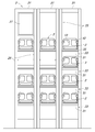
- FIG. 2 is a front view of the battery changer 3.
- FIG. 3 is a side view of the battery changer 3.
- a plurality of battery charging modules 23 are provided in a state of being supported by a support post 25 (support).
- a pair of support posts 25 are provided on the left and right sides of the battery charging module 23.
- the battery charging modules 23 are arranged in a plurality of stages vertically. In the example shown in FIG. 2, the battery charging modules 23 are arranged in four stages vertically.
- a battery charging unit 21 is composed of a battery charging module 23 and a support post 25, and one or a plurality of the battery charging units 21 are arranged side by side to form a battery exchange 3.
- the battery exchange 3 is composed of three battery charging units 21.
- a display module 27 is provided in one battery charging unit 21 that constitutes the battery exchange 3.
- the display module 27 normally operates as a digital signage for displaying contents such as advertisements, and when it detects a person who has visited the battery replacement, a guidance screen for battery replacement is displayed. Similar to the battery charging module 23, the display module 27 is fixed to the support posts 25 in a state of being sandwiched between the left and right support posts 25.
- the battery pack 2 is mounted on the battery charging module 23 in an inclined state with the handle 12 side facing diagonally upward.
- the battery charging module 23 includes a tray 31 on which one battery pack 2 is mounted.
- the tray 31 includes a bottom surface support portion 32 that supports the bottom surface of the housing 11 of the battery pack 2, and a side surface support portion 33 that supports one side surface of the battery pack 2, and has an L-shape in a side view. ing.
- the battery pack 2 is held in the tray 31 in an inclined state, the height of one stage is lowered, and more battery packs 2 can be accommodated in the vertical direction.
- a display unit 35 for displaying the charging status of the battery pack 2 is provided at the front end of the tray 31 in the battery charging module 23.
- the display unit 35 displays the charged state of the battery pack 2 in different colors, for example, by switching and lighting a light source (LED lamp or the like) of a plurality of colors. For example, the charging completed state (rental available state) is displayed in green, and the charging incomplete state (rental impossible state) is displayed in red.
- a light source LED lamp or the like
- the user When replacing the battery pack 2, the user first searches for an empty battery charging module 23 for returning the battery pack 2, and attaches the battery pack 2 to the tray 31 of the empty battery charging module 23. .. Next, in order to rent out the battery pack 2 in the fully charged state, the user searches for the battery pack 2 in the fully charged state and takes out the fully charged battery pack 2 from the tray 31 of the battery charging module 23.
- a plurality of battery charging modules 23 for charging the battery pack 2 and a plurality of display modules 27 for displaying various screens are attached to the support post 25, but other than such charging and screen display.
- a functional module may be attached to the support post 25.
- a module or the like that generates photovoltaic power may be attached to the support post 25.
- FIG. 4 is an explanatory view showing a mounting structure of the battery charging module 23.
- the battery charging module 23 is detachably fixed to the support post 25 by bolts 37.
- the support post 25 is provided with mounting holes 38 corresponding to the maximum number of battery charging modules 23 that can be mounted in advance. By inserting bolts 37 into the mounting holes 38 and fastening them, the battery charging module 23 can be attached. It is fixed to the support post 25.
- the battery charging module 23 can be easily mounted and removed from the support post 25. Therefore, after the operation of the battery switching machine 3 is started, the battery charging module 23 can be added or removed according to the actual frequency of use of the battery changing machine 3, and the number of battery charging modules 23 to be attached can be freely adjusted. Can be adjusted to. In the example shown in FIG. 4, the battery charging module 23 is attached only to the middle two stages of the four stages.
- the mounting structure of the battery charging module 23 is not limited to bolt fastening, and other removable fixing structures can be adopted. It is advisable to use bolts having a special shape so that only the builder of the battery station can easily remove the bolts, or to attach a concealing member that obscures the existence of the bolts to the support post 25.
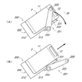
- FIG. 5 is an explanatory view showing the lock mechanism 41 of the battery switchboard 3.
- the battery exchange 3 is provided with a lock mechanism 41 that prevents the battery pack 2 from being taken out from the tray 31 of the battery charging module 23. By preventing the battery pack 2 from being taken out by the lock mechanism 41, it is possible to prevent the battery pack 2 in the uncharged state from being rented out by mistake. Further, when performing user authentication for identifying a user who has visited the battery replacement, it is possible to prevent the battery pack 2 from being erroneously rented to a person who is not a legitimate user.
- the lock mechanism 41 is provided on the support post 25, and the lock pin 42 (lock member) that regulates the movement of the battery pack 2 and the lock pin 42 advance and retreat in the axial direction between the lock position and the unlock position. It has a drive unit 43 to operate.
- the bevel gear 46 and the feed screw 47 are configured to advance and retreat the lock pin 42 in the axial direction according to the rotation of the electric motor 45, but the configuration of the drive unit 43 is It is not limited to the illustrated example.
- the lock pin 42 protrudes toward the handle 12 of the housing 11 in the battery pack 2 to prevent the battery pack 2 from being removed from the tray 31.
- FIG. 5B when the lock pin 42 is retracted, the unlocked state is entered. In this unlocked state, the lock pin 42 is not located on the handle 12 side of the housing 11 in the battery pack 2, so that the battery pack 2 can be removed from the tray 31.
- FIG. 6 is a block diagram showing a schematic configuration of the battery pack 2 and the battery charging module 23.
- the battery pack 2 includes a battery cell 51, a power supply terminal 52, a communication terminal 53, a charge / discharge circuit 54, a memory 55, and a processor 56.
- the power supply terminal 52 transmits the charging power supplied from the battery charging module 23 at the time of charging. Further, the power supply terminal 52 transmits the electric power of the battery cell 51 to the electric vehicle 1 while being mounted on the electric vehicle 1.
- the communication terminal 53 transmits / receives information between the battery charging module 23 and the battery pack 2.
- the power supply terminal 52 may also be used as a communication terminal.
- the charging / discharging circuit 54 has an operation of charging the battery cell 51 with the charging power supplied from the battery charging module 23 and an operation of discharging the battery cell 51 to supply the electric vehicle 1 with the electric power for traveling. Do.
- the memory 55 stores a program executed by the processor 56. Further, the memory 55 stores the battery management information required for managing the battery replacement service.
- This battery management information includes, for example, the ID of the battery pack 2 (individual identification information such as a serial number), the ID of the user using the battery pack 2, an alert indicating an abnormal state of the battery pack 2, the number of times of charging in the past, and the like. History information, deterioration information of the battery cell 51, and the like.
- the processor 56 controls each part of the battery pack 2. For example, various environmental sensors (temperature, humidity, voltage, current) are provided to detect an abnormality or deterioration state of the battery cell 51, and an alert or deterioration information is stored in the memory 55.
- various environmental sensors temperature, humidity, voltage, current
- an alert or deterioration information is stored in the memory 55.
- the battery charging module 23 includes a power supply terminal 61, a communication terminal 62, and an input / output unit 63 in addition to the display unit 35.
- the power supply terminal 61 transmits the charging power supplied from the controller 22 to the battery pack 2 at the time of charging.
- the communication terminal 62 transmits / receives information between the battery charging module 23 and the battery pack 2.
- the power supply terminal 61 may also serve as a communication terminal.
- the input / output unit 63 relays the transmission / reception of information to / from the battery pack 2.
- the controller 22 includes a charge control circuit 71, a power supply unit 72, an input / output unit 73, a communication unit 74, a memory 75, and a processor 76.
- the charge control circuit 71 controls the charging power supplied from the power supply unit 72 to the battery charging module 23.
- the communication unit 74 communicates with the management server 4. Specifically, the battery management information (such as the ID of the battery pack 2) acquired from the battery pack 2 is transmitted to the management server 4. In addition, the communication unit 74 receives control information regarding whether or not charging for each battery pack 2 can be performed and the target charge amount from the management server 4. As a result, the charging timing and the charging amount can be controlled for each battery pack 2. Further, the communication unit 74 may receive the loan availability information of the battery pack 2 from the management server 4 and perform the lending process of selecting the battery pack 2 to be rented by the processor 76.
- the battery management information such as the ID of the battery pack 2 acquired from the battery pack 2 is transmitted to the management server 4.
- the communication unit 74 receives control information regarding whether or not charging for each battery pack 2 can be performed and the target charge amount from the management server 4. As a result, the charging timing and the charging amount can be controlled for each battery pack 2. Further, the communication unit 74 may receive the loan availability information of the battery pack 2 from the management server 4 and perform the lending process of selecting
- the communication unit 74 transmits the authentication information (face image, RFID user ID, etc.) acquired for the purpose of user authentication to the management server 4 or the authentication server (not shown), and authenticates from the management server 4 or the authentication server.
- the result may be received and the processor 76 may determine whether or not to lend.
- the memory 75 stores a program executed by the processor 76.
- the processor 76 controls the charging of the battery pack 2 in the battery charging module 23. Specifically, the charge control circuit 71 is controlled based on the information acquired from the battery pack 2 via the input / output unit 73. Further, the display unit 35 is controlled based on the charging information acquired from the battery pack 2, and the display unit 35 displays the color corresponding to the charging state of the battery pack 2. It also controls the drive unit 43 that moves the lock pin 42 that prevents the battery pack 2 from being taken out from the tray 31 of the battery charging module 23.
- Information on the traveling locus of the electric vehicle 1 for example, the position information of each time of the electric vehicle 1 acquired by using a positioning system such as GPS is stored in the memory 55 in the battery pack 2 and the information is stored.
- the information may be transmitted from the battery pack 2 to the management server 4 via the battery exchange 3.
- the electric vehicle 1 is equipped with a camera as a drive recorder
- the moving image is stored in the memory 55 in the battery pack 2 within the capacity reserved for the drive recorder, and the moving image is stored in the memory 55.
- the video may be transmitted from the battery pack 2 to the management server 4 via the battery switch 3.
- FIG. 7 is an explanatory diagram showing a guide structure of the battery pack 2 in the battery charging module 23.
- a power supply terminal 61 and a communication terminal 62 are provided on the bottom support portion 32 of the tray 31 in the battery charging module 23.
- a power supply terminal 52 and a communication terminal 53 are provided on the bottom surface of the battery pack 2.
- the bottom support portion 32 and the side support portion 33 of the tray 31 are provided with guide portions 81 and 82, respectively.
- the guide portions 81 and 82 guide the battery pack 2 to a regular mounting position where the power supply terminal 61 and the communication terminal 62 on the tray 31 side and the power supply terminal 52 and the communication terminal 53 on the battery pack 2 side are aligned.
- FIG. 8 is an explanatory diagram showing a lock mechanism 101 of the battery exchange 3 according to the first modification of the first embodiment.
- a lock pin 42 (lock member) constituting a lock mechanism 41 for preventing the battery pack 2 from being taken out from the battery charging module 23 and a drive unit 43 thereof are provided on the support post 25.
- the hook 102 (lock member) constituting the lock mechanism 101 and the drive unit 103 thereof are provided in the battery charging module 23.
- the hook 102 provided on the tray 31 engages with the stopper 104 provided on the battery pack 2, so that the battery pack 2 can be removed from the tray 31. Be blocked.
- the hook 102 since the hook 102 is not engaged with the stopper 104 in the unlocked state, the battery pack 2 can be removed from the tray 31.
- the hook 102 (lock member) is engaged with the stopper 104 to prevent the battery pack 2 from being taken out, but the lock mechanism is limited to such a configuration. Not done.
- the lock member constituting the lock mechanism and the drive unit thereof are provided in the battery charging module on the premise of the configuration according to the first embodiment, but on the premise of the configuration according to other embodiments described later.
- the lock member constituting the lock mechanism and the drive unit thereof can also be provided in the battery charging module.
- FIG. 9 is an explanatory diagram showing a lock mechanism 111 of the battery exchange 3 according to the second modification of the first embodiment.
- the hook 102 (lock member) constituting the lock mechanism 101 for preventing the battery pack 2 from being taken out from the tray 31 of the battery charging module 23 and the driving unit 103 thereof are the battery charging module 23.
- the hook 112 (lock member) constituting the lock mechanism 111 and the drive unit 113 thereof are provided in the battery pack 2.
- the hook 112 provided on the battery pack 2 engages with the stopper 114 provided on the tray 31, so that the battery pack 2 can be removed from the tray 31. Be blocked.
- the hook 112 since the hook 112 is not engaged with the stopper 114 in the unlocked state, the battery pack 2 can be removed from the tray 31.
- the hook 112 (lock member) is engaged with the stopper 114 to prevent the battery pack 2 from being taken out, but the lock mechanism is limited to such a configuration. Not done.
- the lock member (hook 112) provided on the battery pack 2 is engaged with the tray 31 of the battery charging module 23 to restrain the battery pack 2, but the battery pack 2 is used.
- the provided lock member may be engaged with the support post 25 (support body) to restrain the battery pack 2.
- a lock pin (lock member) is provided on the side surface of the battery pack 2 so as to be retractable, and the lock pin is fitted into a hole provided in the support post 25 so that the battery pack 2 is restrained. May be good.
- the lock member and the drive unit thereof constituting the lock mechanism are provided in the battery pack on the premise of the configuration according to the first embodiment, but on the premise of the configuration according to other embodiments described later. It is also possible to provide the lock member constituting the lock mechanism and the drive unit thereof in the battery pack.
- FIG. 10 is a front view of the battery exchange 201 according to the second embodiment.
- FIG. 11 is a plan view of the battery switch 201.
- a plurality of battery charging modules 202 are provided in a state of being supported by a support post 203 (support). Further, the plurality of battery charging modules 202 are provided around the support post 203 at predetermined intervals. In the example shown in FIG. 10, four battery charging modules 202 are arranged at a right angle of 90 degrees.
- the battery pack 2 is mounted on the tray 205 of the battery charging module 202 in an inclined state with the handle 12 side facing diagonally upward.
- the battery charging module 202 is arranged in a plurality of stages vertically. In the example shown in FIG. 10, the battery charging modules 202 are arranged in two stages vertically.
- the user orbits around the battery changer 201 when searching for an empty tray 205 or a fully charged battery.
- the upper battery charging module 202 and the lower battery charging module 202 are arranged so as to be displaced from each other in mounting positions.
- the upper battery charging module 23 and the lower battery charging module 202 are arranged so as to be displaced by 45 degrees from each other.
- the tray 205 is attached to the support post 203 with the side surface side fixed to the support post 203.
- the protruding dimension in the radial direction can be kept short to save space.
- the battery charging module 202 is detachably fixed to the support post 203 with bolts (not shown). As a result, the number of battery charging modules 202 attached to the support post 203 can be adjusted according to the actual frequency of use of the battery exchange 201.
- the battery exchange 201 is formed in a form reminiscent of a tree as a whole. That is, the radially extending portion of the upper end of the support post 203 is reminiscent of a tree branch, and the plurality of battery charging modules 202 are pronounced of the fruit of a tree. Further, by providing a lamp at the radially extending portion of the upper end portion of the support post 203, it is possible to impart a function as a street lamp. In addition, eaves that block rain and sunlight may be provided at the radially extending portion of the upper end of the support post 203.
- FIG. 12 is an explanatory diagram showing a lock mechanism 221 of the battery switch 201.
- the battery charging module 202 is provided with an arm 222 and a driving unit 223 thereof that form a lock mechanism 221 that prevents the battery pack 2 from being taken out from the tray 205.
- the base end side of the arm 222 is rotatably fixed to the tray 205.
- a lock pin 225 (lock member) is provided on the tip end side of the arm 222.
- the drive unit 223 includes an actuator such as an electric motor.
- the lock pin 225 is located on the handle 12 side of the housing 11 in the battery pack 2, so that the removal of the battery pack 2 from the tray 205 is prevented.
- the arm 222 when the arm 222 is rotated, it transitions to the unlocked state. In this unlocked state, the lock pin 225 is not located on the handle 12 side of the housing 11 in the battery pack 2, so that the battery pack 2 can be removed from the tray 205.
- the tray 205 of the battery charging module 202 has a bottom support portion 212 that supports the bottom surface of the housing 11 of the battery pack 2 and a side support portion that supports one side surface of the battery pack 2, as in the first embodiment. It is equipped with 213 and has an L-shape when viewed from the side. Further, on the front surface of the tray 505, a display unit 231 for displaying the charging state of the battery pack 2 is provided.
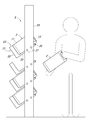
- FIG. 13 is a front view of the battery changer 301 according to the third embodiment.
- FIG. 14 is a side view of the battery switch 301.
- the periphery of the support post 303 in a state where a plurality of battery charging modules 302 are supported by the support post 303 (support).
- a plurality of battery charging modules 302 are attached to the support post 303 via a support frame 305 that is rotatable around the central axis (vertical axis) of the support post 303. It is supported.
- the battery charging module 302 has a tray 306 for holding the battery pack 2.
- the battery pack 2 is held in the tray 306 in an upright state.
- the tray 306 is provided with a recess 307, and the bottom of the battery pack 2 is fitted into the recess 307. The user fits the battery pack 2 into the recess 307 of the tray 306 from above the tray 306, so that the battery pack 2 is mounted on the tray 306.
- the support frame 305 has a central tubular portion 311, a tray support portion 312, and a handle portion 313.
- the tray support portion 312 and the handle portion 313 project radially in the radial direction from the outer peripheral surface of the central tubular portion 311.
- the central tubular portion 311 is rotatably fixed to the support post 303 around the central axis (vertical axis) of the support post 303.
- the tray 306 is fixed to the tray support portion 312 and the handle portion 313. The user can easily rotate the support frame 305 and the battery charging module 302 supported by the support frame 305 by pushing the handle portion 313.
- the battery charging module 302 rotates around the support post 303, so that when searching for an empty battery charging module 302 or a fully charged battery pack 2, the user can use the surroundings of the battery switch 301. There is no need to go around.
- the handle portion 313 is provided with a lock pin 322 (lock member) constituting the lock mechanism 321 and a drive unit 323 for advancing and retreating the lock pin 322.
- the lock pin 322 projects toward the handle 12 of the housing 11 of the battery pack 2 to prevent the battery pack 2 from being taken out.
- a display unit 331 that displays the charging status of the battery pack 2 is provided on the front surface of the handle unit 313.
- the tray 306 of the battery charging module 302 is detachably fixed to the support frame 305 with bolts (not shown). Thereby, the number of battery charging modules 302 attached to the support frame 305 can be adjusted according to the actual frequency of use of the battery exchange 301.
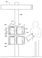
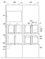
- FIG. 15 is a front view of the battery exchange 401 according to the fourth embodiment.
- FIG. 16 is a side view of the battery switch 401.
- the battery charging module 402 is provided in the battery switching machine 401 in a state of being supported by the support panel 403 (support).
- a plurality of battery charging modules 402 are provided side by side in the horizontal direction and the vertical direction along the front surface of the support panel 403.
- the battery charging unit 411 is composed of the support panel 403 and the plurality of battery charging modules 402 supported by the support panel 403. One or a plurality of the battery charging units 411 are arranged side by side to form the battery exchange 401. In one battery charging unit 411, a display 412 is provided on the support panel 403.
- the battery charging module 402 includes a tray 405 on which the battery pack 2 is mounted and a bracket 406 that supports the tray 405. Similar to the third embodiment (see FIG. 13), the battery pack 2 is mounted on the tray 405 in an upright state. As a result, the depth of the battery exchange 401 can be shortened.
- the battery charging module 402 is fixed to the front side of the support panel 403. Both the tray 405 and the bracket 406 may be fixed to the support panel 403, but only the bracket 406 may be fixed to the support panel 403.
- the tray 405 and the bracket 406 of the battery charging module 402 are detachably fixed to the support panel 403 with bolts (not shown).
- the bracket 406 may be fixed to the support panel 403 so that only the tray 405 can be attached and detached.
- the bracket 406 is provided with a lock pin 422 (lock member) constituting the lock mechanism 421 and a drive unit 423 for moving the lock pin 422 forward and backward.
- the lock pin 422 projects toward the handle 12 of the housing 11 of the battery pack 2 to prevent the battery pack 2 from being taken out.
- a display unit 431 for displaying the charging status of the battery pack 2 is provided on the front surface of the tray 405.
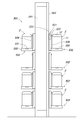
- FIG. 17 is a front view of the battery switch 501 according to the fifth embodiment.
- FIG. 18 is a side view of the battery switch 501.
- the battery charging module 502 is provided in the battery exchange 501 in a state of being supported by the support post 503 (support).
- the battery charging module 502 is arranged on both the left and right sides of the support post 503. Further, the battery charging module 502 is provided in a plurality of stages vertically along the support post 503.
- the battery charging module 502 includes a tray 505 on which the battery pack 2 is mounted and a bracket 506 that supports the tray 505, as in the fourth embodiment.
- the battery pack 2 is mounted on the tray 505 in an upright state.
- the bracket 506 is fixed to the support post 25.
- the battery charging module 502 is detachably fixed to the support post 503 with bolts (not shown). This makes it possible to easily adjust the number of battery charging modules 502 attached to the support post 503 according to the actual frequency of use of the battery switch 501.
- the bracket 506 may be fixed to the support post 503 so that only the tray 505 can be attached and detached.
- the bracket 506 includes a lock pin 522 (lock member) constituting a lock mechanism 521 that prevents the battery pack 2 from being taken out from the tray 205, and a drive unit 523 that moves the lock pin 522 forward and backward. And are provided.
- the lock pin 522 projects toward the handle 12 of the housing 11 of the battery pack 2 to prevent the battery pack 2 from being taken out.
- a display unit 531 for displaying the charging status of the battery pack 2 is provided on the front surface of the tray 505.
- a vertically long display 541 that functions as a digital signage for displaying contents such as advertisements is provided.
- FIG. 19 is a front view of the battery switch 601 according to the sixth embodiment.
- FIG. 20 is a side view of the battery switch 601.
- the battery charging module 602 is provided in the battery switching machine 601 in a state of being supported on both the left and right sides of the support post 603. There is.
- the upper end of the support post 603 is connected to the support panel 604 provided on the back side of the support post 603, and the support post 603 is provided in a state of being supported by the support panel 604.
- the battery charging module 602 includes a tray 607 and a bracket 608, as in the fourth embodiment.
- a display unit 612 is provided adjacent to the battery charging unit 611 composed of the battery charging module 602, the support post 603, and the support panel 604.
- a display 613 is provided on the support panel 614 of the display unit 612.
- a screen related to face recognition and the like is displayed on the display 613, and the user can operate the screen.
- Privacy panels 615 are provided on both the left and right sides of the display 613.
- the bracket 608 is provided with a lock mechanism 621 for preventing the battery pack 2 from being taken out from the tray 607. Further, a display unit 631 for displaying the charging status of the battery pack 2 is provided on the front surface of the tray 505.
- the battery charging module 602 is detachably fixed to the support post 603 with bolts (not shown). As a result, the number of battery charging modules 23 attached to the support post 25 can be easily adjusted according to the actual frequency of use of the battery switch 601.
- the bracket 608 may be fixed to the support post 503 so that only the tray 607 can be attached and detached.
- the support panels 604 and 614 are formed in a curved shape so that the upper end side is inclined toward the front side, and the upper end side of the support panels 604 and 614 functions as an eave to block rain and sunlight. ..
- FIG. 21 is an explanatory diagram showing the battery pack 701 and the battery charging module 702 according to the seventh embodiment.
- the power supply terminal 52 provided in the battery charging module 23 and the power supply terminal 61 provided in the battery pack 2 are joined to charge the battery pack 2 from the battery charging module 23.
- the electric power for charging is supplied, in the present embodiment, the electric power for charging is supplied from the battery charging module 702 to the battery pack 701 by wireless power supply (non-contact power supply) using electromagnetic induction.
- a power transmission coil 705 is provided on the tray 704 of the battery charging module 702.
- the battery pack 701 is provided with a power receiving coil 707 in addition to the battery cell 51 and the power supply terminal 52.
- the tray 704 of the battery charging module 702 has a bottom support portion 712 that supports the bottom surface of the housing of the battery pack 701 and a side support portion 713 that supports one side surface of the battery pack 2. It has an L-shape when viewed from the side. Further, a display unit 731 for displaying the charging status of the battery pack 2 is provided on the front surface of the tray 704.
- the battery pack 2 and the battery charging module 23 according to the first embodiment are configured by applying wireless power supply, but the battery pack and the battery charging module according to another embodiment are wirelessly supplied. It is also possible to apply power supply.
- FIG. 22 is a block diagram showing a schematic configuration of the battery pack 701 and the battery charging module 702.
- the configuration of the controller 22 is the same as that of the first embodiment (see FIG. 6).
- the battery pack 701 includes a power receiving circuit 741 and a wireless communication unit 742 in addition to the power receiving coil 707.
- the wireless power feeding unit 743 is configured by the power receiving coil 707 and the power receiving circuit 741.
- the power receiving circuit 741 converts the alternating current induced in the power receiving coil 707 by electromagnetic induction with the power transmitting coil 705 into electric power (DC power) of a predetermined voltage, and outputs the electric power to the charging / discharging circuit 54. .. Others are the same as those of the first embodiment (see FIG. 6).
- the wireless communication unit 742 performs wireless communication (short-range communication) with the battery charging module 702. Specifically, the battery management information (such as the ID of the battery pack 2) stored in the memory 55 is transmitted to the battery charging module 702.
- wireless near field communication
- wireless includes, for example, Wi-Fi (registered trademark), Bluetooth (registered trademark), infrared communication, RFID (Radio Frequency Identifier), and the like.
- the power supply terminal 52 and the communication terminal 53 are not used, but the power supply terminal 52 and the communication terminal 53 are used with the electric vehicle 1. Since power supply and communication are performed by wire, a power supply terminal 52 and a communication terminal 53 are provided.
- the battery charging module 702 includes a power transmission circuit 751 and a wireless communication unit 752 in addition to the power transmission coil 705.
- the power transmission coil 705 and the power transmission circuit 751 constitute a wireless power supply unit 753.
- the power transmission circuit 751 converts the power (DC power) supplied from the controller 22 into an AC voltage having a predetermined frequency and supplies it to the power transmission coil 705.
- the wireless communication unit 752 performs wireless communication (short-range communication) with the battery pack 701. Specifically, the battery management information (such as the ID of the battery pack 2) transmitted from the battery pack 701 is received.
- wireless near field communication
- wireless includes, for example, Wi-Fi (registered trademark), Bluetooth (registered trademark), infrared communication, RFID, and the like.
- the battery charging module, the battery replacement device, and the battery device according to the present disclosure may be inexpensive and easily dealt with when it becomes necessary to adjust the scale of the battery replacement device even after the service is put into operation. It has a possible effect, and is useful as a battery charging module, a battery replacement device, a battery device, and the like that hold a battery device and are attached to a plurality of supports to form a battery replacement device.
- Electric vehicle 1 Electric vehicle 2 Battery pack (battery device) 3 Battery exchange (battery exchange device) 11 Housing 12 Handle 23 Battery charging module 25 Support post (support) 31 Tray 35 Display unit 37 Bolt 38 Mounting hole 41 Lock mechanism 42 Lock pin 43 Drive unit 52 Power supply terminal 53 Communication terminal 61 Power supply terminal 62 Communication terminal
Landscapes
- Engineering & Computer Science (AREA)
- Power Engineering (AREA)
- Chemical & Material Sciences (AREA)
- Transportation (AREA)
- Mechanical Engineering (AREA)
- General Chemical & Material Sciences (AREA)
- Electrochemistry (AREA)
- Chemical Kinetics & Catalysis (AREA)
- Manufacturing & Machinery (AREA)
- Computer Networks & Wireless Communication (AREA)
- Sustainable Energy (AREA)
- Sustainable Development (AREA)
- Life Sciences & Earth Sciences (AREA)
- Combustion & Propulsion (AREA)
- Charge And Discharge Circuits For Batteries Or The Like (AREA)
- Electric Propulsion And Braking For Vehicles (AREA)
- Battery Mounting, Suspending (AREA)
Abstract
[Problem] To make it possible to inexpensively and easily deal with a situation where the scale of a battery exchange device needs to be adjusted, even after the operation of service is started. [Solution] A battery exchange device 3 is formed by attaching a plurality of battery charging modules 23 for holding a battery pack 2 to a support post 25. The battery charging modules are fixed to the support post in a detachable manner. The battery charging modules are each provided with a tray 31 for guiding the battery pack to a predetermined installation position and holding the same. The tray has a power supply terminal for transmitting charging power to the battery pack, a communication terminal through which battery management information is transmitted from the battery pack, and a display unit 35 for displaying a state of charge of the battery pack.
Description
本開示は、バッテリ装置を保持し、支持体に複数取り付けられてバッテリ交換装置を構成するバッテリ充電モジュール、バッテリ交換装置、およびバッテリ装置に関するものである。
The present disclosure relates to a battery charging module, a battery replacement device, and a battery device that hold a battery device and are attached to a plurality of supports to form a battery replacement device.
近年、排気ガスによる大気汚染や燃料コストの問題を解消する観点から、電動バイクなどの電動車両が注目されている。このような電動車両では、バッテリ装置の性能向上により航続距離が伸びているが、バッテリ装置の充電が支障となって、長時間の連続走行ができないという不便がある。
In recent years, electric vehicles such as electric motorcycles have been attracting attention from the viewpoint of solving the problems of air pollution and fuel cost due to exhaust gas. In such an electric vehicle, the cruising range is extended by improving the performance of the battery device, but there is an inconvenience that the charging of the battery device is hindered and continuous running for a long time is not possible.
そこで、このような不便を解消するため、従来、電動車両に、着脱可能なバッテリ装置を搭載して、バッテリステーションにおいて、残量が少なくなったバッテリ装置と充電済みのバッテリ装置とを交換できるようにして、長時間の連続走行を実現するバッテリ交換サービスが知られている。
Therefore, in order to eliminate such inconvenience, conventionally, a detachable battery device is mounted on an electric vehicle so that a battery device having a low remaining amount can be replaced with a charged battery device at a battery station. A battery replacement service that realizes continuous running for a long time is known.
このバッテリ交換サービスでは、バッテリステーションにバッテリ交換装置を設置して、そのバッテリ交換装置において、ユーザが持ち込んだバッテリ装置を収容して、その代わりに、充電済みのバッテリ装置をユーザに貸し出すようにすればよい。このとき、バッテリ装置が比較的重量が大きいため、バッテリ交換作業をユーザが容易に行えるようにして、ユーザの負担を軽減すると、ユーザの利便性を高めることができる。
In this battery replacement service, a battery replacement device is installed in the battery station, and the battery replacement device accommodates the battery device brought in by the user, and instead lends the charged battery device to the user. Just do it. At this time, since the battery device is relatively heavy, the user can easily perform the battery replacement work to reduce the burden on the user, and the convenience of the user can be improved.
このようなバッテリ交換作業を行うユーザの負担を軽減するものとして、従来、収納されたバッテリ装置の一端を突出させることで、バッテリ装置の取り出しの作業を容易にする技術が知られている(特許文献1参照)。また、バッテリ装置の収容部が手前側に傾動することで、バッテリ装置の収容および取り出しの作業を容易にする技術が知られている(特許文献2参照)。
As a technique for reducing the burden on the user who performs such battery replacement work, a technique for facilitating the work of taking out the battery device by projecting one end of the stored battery device has been conventionally known (patented). Reference 1). Further, there is known a technique for facilitating the work of accommodating and taking out the battery device by tilting the accommodating portion of the battery device toward the front side (see Patent Document 2).
さて、バッテリ交換サービスの需要の程度は、設置場所に応じて異なる。このため、需要の程度を予測して、その予測結果に応じた規模でバッテリ交換装置を設置する。ところが、バッテリ交換サービスの運用を開始してみると、バッテリ交換サービスの実際の利用状況が予測結果と大きく異なることが判明することが多い。このため、サービスの運用を開始した後に、バッテリ交換装置の規模を調整する必要が生じる。
By the way, the degree of demand for battery replacement service varies depending on the installation location. Therefore, the degree of demand is predicted, and the battery replacement device is installed on a scale according to the prediction result. However, when the operation of the battery replacement service is started, it is often found that the actual usage status of the battery replacement service is significantly different from the predicted result. Therefore, it becomes necessary to adjust the scale of the battery replacement device after starting the operation of the service.
一方、特許文献1に開示された従来の技術では、スロットを蓋で覆って、利用可能なスロットの数を増減することで、バッテリ交換サービスの実際の需要に応じた適切な規模に調整することができる。また、特許文献2に開示された従来の技術でも、連結するバッテリ充電ロッカーの数を増減することで、バッテリ交換装置の規模を調整することができる。しかしながら、これらの従来の技術では、サービスの運用を開始した後に、バッテリ交換装置の規模を調整する際に、安価かつ簡単に対応できないという問題があった。
On the other hand, in the conventional technique disclosed in Patent Document 1, the slots are covered with a lid and the number of available slots is increased or decreased to adjust the scale appropriately according to the actual demand of the battery replacement service. Can be done. Further, even in the conventional technique disclosed in Patent Document 2, the scale of the battery replacement device can be adjusted by increasing or decreasing the number of battery charging lockers to be connected. However, these conventional techniques have a problem that they cannot be cheaply and easily dealt with when adjusting the scale of the battery replacement device after starting the operation of the service.
そこで、本開示は、サービスの運用を開始した後でも、バッテリ交換装置の規模を調整する必要が生じた場合には、安価かつ簡単に対応することができるバッテリ充電モジュール、バッテリ交換装置、およびバッテリ装置を提供することを主な目的とする。
Therefore, the present disclosure discloses a battery charging module, a battery replacement device, and a battery that can be cheaply and easily dealt with when it becomes necessary to adjust the scale of the battery replacement device even after the service is put into operation. The main purpose is to provide the device.
本開示のバッテリ充電モジュールは、バッテリ装置を保持し、支持体に複数取り付けられてバッテリ交換装置を構成するバッテリ充電モジュールであって、前記支持体に着脱可能に固定され、前記バッテリ装置を所定の装着位置に案内してそのバッテリ装置を保持するトレイを備え、このトレイは、前記バッテリ装置に充電用電力を伝送する給電端子と、前記バッテリ装置からのバッテリ管理情報を伝送する通信端子と、を有する構成とする。
The battery charging module of the present disclosure is a battery charging module that holds a battery device and is attached to a plurality of supports to form a battery replacement device, and is detachably fixed to the support to attach the battery device to a predetermined value. A tray that guides the battery device to the mounting position and holds the battery device is provided, and the tray has a power supply terminal that transmits charging power to the battery device and a communication terminal that transmits battery management information from the battery device. It has a configuration.
また、本開示のバッテリ交換装置は、バッテリ装置を保持するバッテリ充電モジュールを支持体に複数取り付けて構成されたバッテリ交換装置であって、前記バッテリ充電モジュールは、前記支持体に着脱可能に固定され、前記バッテリ装置を所定の装着位置に案内してそのバッテリ装置を保持するトレイを備え、このトレイは、前記バッテリ装置に充電用電力を伝送する給電端子と、前記バッテリ装置からのバッテリ管理情報を伝送する通信端子と、を有し、前記バッテリ充電モジュールおよび前記支持体のいずれかは、前記バッテリ装置の前記装着位置からの取り出しを阻止するロック部材およびその駆動部と、前記バッテリ装置の充電状態を表示する表示部と、を有する構成とする。
Further, the battery replacement device of the present disclosure is a battery replacement device configured by attaching a plurality of battery charging modules holding the battery device to a support, and the battery charging module is detachably fixed to the support. A tray for guiding the battery device to a predetermined mounting position and holding the battery device is provided, and the tray provides a power supply terminal for transmitting charging power to the battery device and battery management information from the battery device. A lock member having a communication terminal for transmission and any of the battery charging module and the support for preventing the battery device from being taken out from the mounting position, a driving unit thereof, and a charging state of the battery device. It is configured to have a display unit for displaying.
また、本開示のバッテリ装置は、前記バッテリ充電モジュールに保持されるバッテリ装置であって、自装置の前記装着位置からの取り出しを阻止するロック部材およびその駆動部を有する構成とする。
Further, the battery device of the present disclosure is a battery device held in the battery charging module, and has a configuration including a lock member for preventing the self-device from being taken out from the mounting position and a driving unit thereof.
本開示によれば、バッテリ交換サービスの実際の利用状況に応じて、バッテリ充電モジュールの増設や撤去を容易に行うことができる。これにより、サービスの運用を開始した後でも、バッテリ交換装置の規模を調整する必要が生じた場合には、安価かつ簡単に対応することができる。
According to the present disclosure, the battery charging module can be easily added or removed according to the actual usage status of the battery replacement service. As a result, even after the service has started operation, if it becomes necessary to adjust the scale of the battery replacement device, it can be handled inexpensively and easily.
前記課題を解決するためになされた第1の発明は、バッテリ装置を保持し、支持体に複数取り付けられてバッテリ交換装置を構成するバッテリ充電モジュールであって、前記支持体に着脱可能に固定され、前記バッテリ装置を所定の装着位置に案内してそのバッテリ装置を保持するトレイを備え、このトレイは、前記バッテリ装置に充電用電力を伝送する給電端子と、前記バッテリ装置からのバッテリ管理情報を伝送する通信端子と、を有する構成とする。
The first invention made to solve the above problems is a battery charging module that holds a battery device and is attached to a plurality of supports to form a battery replacement device, and is detachably fixed to the support. A tray for guiding the battery device to a predetermined mounting position and holding the battery device is provided, and the tray provides a power supply terminal for transmitting charging power to the battery device and battery management information from the battery device. It is configured to have a communication terminal for transmission.
これによると、バッテリ交換サービスの実際の利用状況に応じて、バッテリ充電モジュールの増設や撤去を容易に行うことができる。これにより、サービスの運用を開始した後でも、バッテリ交換装置の規模を調整する必要が生じた場合には、安価かつ簡単に対応することができる。
According to this, the battery charging module can be easily added or removed according to the actual usage status of the battery replacement service. As a result, even after the service has started operation, if it becomes necessary to adjust the scale of the battery replacement device, it can be handled inexpensively and easily.
また、第2の発明は、更に、前記トレイが、前記バッテリ装置の充電状態を表示する表示部を有する構成とする。
Further, the second invention further comprises a configuration in which the tray has a display unit for displaying the charging status of the battery device.
これによると、バッテリ充電モジュールに装着されたバッテリ装置ごとの充電状態をユーザが確認することができる。
According to this, the user can check the charging status of each battery device mounted on the battery charging module.
また、第3の発明は、更に、前記トレイが、前記バッテリ装置の前記装着位置からの取り出しを阻止するロック部材およびその駆動部を有する構成とする。
Further, the third invention further comprises a configuration in which the tray includes a lock member for preventing the battery device from being taken out from the mounting position and a driving portion thereof.
これによると、充電未了状態のバッテリ装置が誤って貸し出されることを避けることができ、また、バッテリ装置が地震の揺れで落下して破損することを避けることができる。
According to this, it is possible to prevent the uncharged battery device from being rented out by mistake, and it is possible to prevent the battery device from falling and being damaged by the shaking of the earthquake.
また、第4の発明は、前記トレイが、前記バッテリ装置を、取っ手を斜め上方に向けた傾斜状態で保持する構成とする。
Further, the fourth invention has a configuration in which the tray holds the battery device in an inclined state with the handle facing diagonally upward.
これによると、バッテリ装置をトレイに装着した状態の高さ寸法を小さく抑えることができるため、より多くのバッテリ装置をバッテリ交換装置に収容することができる。
According to this, since the height dimension when the battery device is mounted on the tray can be kept small, more battery devices can be accommodated in the battery replacement device.
また、第5の発明は、前記トレイが、前記バッテリ装置を、取っ手を上方に向けた直立状態で保持する構成とする。
Further, the fifth invention has a configuration in which the tray holds the battery device in an upright state with the handle facing upward.
これによると、バッテリ装置をトレイに装着した状態の奥行き寸法を小さく抑えることができるため、バッテリ交換装置の省スペース化を図ることができる。
According to this, the depth dimension when the battery device is mounted on the tray can be kept small, so that the space of the battery replacement device can be saved.
また、第6の発明は、バッテリ装置を保持するバッテリ充電モジュールを支持体に複数取り付けて構成されたバッテリ交換装置であって、前記バッテリ充電モジュールは、前記支持体に着脱可能に固定され、前記バッテリ装置を所定の装着位置に案内してそのバッテリ装置を保持するトレイを備え、このトレイは、前記バッテリ装置に充電用電力を伝送する給電端子と、前記バッテリ装置からのバッテリ管理情報を伝送する通信端子と、を有し、前記バッテリ充電モジュールおよび前記支持体のいずれかは、前記バッテリ装置の前記装着位置からの取り出しを阻止するロック部材およびその駆動部と、前記バッテリ装置の充電状態を表示する表示部と、を有する構成とする。
The sixth invention is a battery replacement device configured by attaching a plurality of battery charging modules for holding a battery device to a support, and the battery charging module is detachably fixed to the support and is fixed to the support. A tray for guiding the battery device to a predetermined mounting position and holding the battery device is provided, and this tray transmits a power supply terminal for transmitting charging power to the battery device and battery management information from the battery device. Any of the battery charging module and the support having a communication terminal indicates a lock member and a driving unit thereof for preventing the battery device from being taken out from the mounting position, and a charging state of the battery device. The configuration is such that the display unit and the display unit are provided.
これによると、第1の発明と同様に、サービスの運用を開始した後でも、バッテリ交換装置の規模を調整する必要が生じた場合には、安価かつ簡単に対応することができる。さらに、充電未了状態のバッテリ装置が誤って貸し出されることを避けることができ、また、バッテリ装置が地震の揺れで落下して破損することを避けることができる。
According to this, as in the case of the first invention, if it becomes necessary to adjust the scale of the battery replacement device even after the service is started, it can be dealt with inexpensively and easily. Further, it is possible to prevent the uncharged battery device from being rented out by mistake, and it is possible to prevent the battery device from falling and being damaged by the shaking of an earthquake.
また、第7の発明は、前記支持体が、前記バッテリ充電モジュールごとに、前記ロック部材および前記駆動部を有する構成とする。
Further, the seventh invention has a configuration in which the support has the lock member and the drive unit for each battery charging module.
これによると、バッテリ充電モジュールに装着されたバッテリ装置のロックを個別に行うことができる。また、ロック機構をバッテリ充電モジュールに設けなくて済むため、バッテリ充電モジュールの構成を簡素化することができる。
According to this, the battery device attached to the battery charging module can be locked individually. Further, since the lock mechanism does not need to be provided in the battery charging module, the configuration of the battery charging module can be simplified.
また、第8の発明は、前記バッテリ充電モジュールが、前記支持体に対して、略鉛直方向の軸周りに回動可能に取り付けられている構成とする。
Further, the eighth invention has a configuration in which the battery charging module is rotatably attached to the support around an axis in a substantially vertical direction.
これによると、バッテリ充電モジュールを回動する操作を行うことで、空き状態のバッテリ充電モジュールや充電完了状態のバッテリ装置を探すことができる。これにより、ユーザがバッテリ交換装置の周囲を周回する必要がないため、ユーザの利便性を高めることができる。
According to this, by performing an operation of rotating the battery charging module, it is possible to search for an empty battery charging module or a battery device in a fully charged state. As a result, the user does not have to go around the battery replacement device, which can improve the convenience of the user.
また、第9の発明は、前記バッテリ充電モジュールに保持されるバッテリ装置であって、自装置の前記装着位置からの取り出しを阻止するロック部材およびその駆動部を有する構成とする。
Further, the ninth invention is a battery device held in the battery charging module, which includes a lock member for preventing the self-device from being taken out from the mounting position and a driving unit thereof.
これによると、充電未了状態のバッテリ装置が誤って貸し出されることを避けることができ、また、バッテリ装置が地震の揺れで落下して破損することを避けることができる。なお、バッテリ装置に設けられたロック部材が支持体に係合する構成と、バッテリ装置に設けられたロック部材がバッテリ充電モジュールに係合する構成とがあり、いずれでも、バッテリ装置の取り出しを阻止することができる。
According to this, it is possible to prevent the uncharged battery device from being rented out by mistake, and it is possible to prevent the battery device from falling and being damaged by the shaking of the earthquake. In addition, there are a configuration in which the lock member provided in the battery device engages with the support and a configuration in which the lock member provided in the battery device engages with the battery charging module, and in either case, the removal of the battery device is prevented. can do.
以下、本開示の実施の形態を、図面を参照しながら説明する。
Hereinafter, embodiments of the present disclosure will be described with reference to the drawings.
(第1実施形態)
図1は、第1実施形態に係るバッテリ共用システムの全体構成図である。 (First Embodiment)
FIG. 1 is an overall configuration diagram of a battery sharing system according to the first embodiment.
図1は、第1実施形態に係るバッテリ共用システムの全体構成図である。 (First Embodiment)
FIG. 1 is an overall configuration diagram of a battery sharing system according to the first embodiment.
このバッテリ共用システムは、電動バイクなどの電動車両1に搭載するバッテリパック2(バッテリ装置)を複数のユーザで共用するサービス(バッテリ交換サービス)を提供するものであり、バッテリ交換機3(バッテリ交換装置)と、管理サーバ4と、を備えている。
This battery sharing system provides a service (battery replacement service) in which a battery pack 2 (battery device) mounted on an electric vehicle 1 such as an electric motorcycle is shared by a plurality of users, and a battery switch 3 (battery replacement device). ) And the management server 4.
電動車両1は、バッテリパック2を搭載し、バッテリパック2の電力により走行する。図1に示す例では、電動車両1を電動バイクとしたが、4輪の自動車でもよい。また、車道走行が前提となっていないモビリティ装置である電動車椅子、電動カート、テーマパークやゴルフ場等での乗用カートであってもよい。
The electric vehicle 1 is equipped with the battery pack 2 and runs on the electric power of the battery pack 2. In the example shown in FIG. 1, the electric vehicle 1 is an electric motorcycle, but a four-wheeled vehicle may be used. Further, it may be an electric wheelchair, an electric cart, a passenger cart in a theme park, a golf course, or the like, which is a mobility device that is not premised on driving on a roadway.
バッテリパック2は、筐体11の上部に取っ手12が設けられており、ユーザが取っ手12を把持することで、バッテリパック2を持ち運ぶことができる。また、バッテリパック2は、取っ手12側を上方に向けた直立状態で電動車両1に搭載され、ユーザが取っ手12を把持して、バッテリパック2を引き上げることで取り外すことができる。また、バッテリパック2は、取っ手12側を手前にした状態でバッテリ交換機3に収容され、ユーザが一方の手で取っ手12を把持し、必要に応じてもう一方の手で筐体の側面や底面を支えて、バッテリ交換機3に収容することができる。
The battery pack 2 is provided with a handle 12 on the upper part of the housing 11, and the user can carry the battery pack 2 by grasping the handle 12. Further, the battery pack 2 is mounted on the electric vehicle 1 in an upright state with the handle 12 side facing upward, and can be removed by the user holding the handle 12 and pulling up the battery pack 2. Further, the battery pack 2 is housed in the battery exchange 3 with the handle 12 side facing forward, and the user holds the handle 12 with one hand and, if necessary, the side surface or the bottom surface of the housing with the other hand. Can be accommodated in the battery exchange 3.
バッテリ交換機3は、ユーザから返却されたバッテリパック2を収容して充電すると共に、返却されたバッテリパック2と交換で充電済みのバッテリパック2をユーザに貸し出す。このバッテリ交換機3は、コンビニやガソリンスタンドなどの施設(店舗)に併設されたバッテリステーションに配置される。
The battery switchboard 3 accommodates and charges the battery pack 2 returned by the user, and rents the battery pack 2 that has been charged in exchange for the returned battery pack 2 to the user. The battery exchange 3 is arranged at a battery station attached to a facility (store) such as a convenience store or a gas station.
このバッテリ交換機3は、バッテリ充電ユニット21と、コントローラ22と、で構成される。バッテリ充電ユニット21は、バッテリパック2が1基ずつ装着されるバッテリ充電モジュール23を複数備えている。バッテリ充電ユニット21は1基でもよく複数でもよい。コントローラ22は、バッテリ充電ユニット21を制御する機能と、管理サーバ4と通信を行う機能とを有している。なお、バッテリ交換機3と管理サーバ4とは、例えばインターネットなどのネットワークを介して接続されている。
The battery exchange 3 is composed of a battery charging unit 21 and a controller 22. The battery charging unit 21 includes a plurality of battery charging modules 23 to which one battery pack 2 is mounted. The number of battery charging units 21 may be one or a plurality. The controller 22 has a function of controlling the battery charging unit 21 and a function of communicating with the management server 4. The battery exchange 3 and the management server 4 are connected to each other via a network such as the Internet.
管理サーバ4は、バッテリ交換サービスに加入してバッテリパック2を使用する人物をユーザ(会員)として登録し、バッテリパック2とその貸出先のユーザとを紐付けて管理する。また、管理サーバ4は、バッテリ交換機3でのバッテリパック2の交換状況を管理する。
The management server 4 registers a person who subscribes to the battery replacement service and uses the battery pack 2 as a user (member), and manages the battery pack 2 and the user of the lender in association with each other. Further, the management server 4 manages the replacement status of the battery pack 2 in the battery switchboard 3.
なお、バッテリ交換に訪れたユーザを識別するユーザ認証を行うようにしてもよい。この場合、カメラの撮影画像から顔認証によりユーザを識別するようにしてもよい。また、ユーザが所持するRFID(radio frequency identifier)のタグや、非接触型ICカードや、NFC(Near field communication)の機能を備えたユーザ端末との間の通信で、ユーザを識別するようにしてもよい。また、カメラの撮影画像から、バッテリパック2に添付された2次元コードを読み取ることで、ユーザがバッテリパック2を返却しようとしていることを検知するようにしてもよい。
Note that user authentication may be performed to identify the user who visited the battery replacement. In this case, the user may be identified by face recognition from the image taken by the camera. In addition, the user is identified by communication with an RFID (radio frequency identifier) tag possessed by the user, a non-contact IC card, or a user terminal having an NFC (Near field communication) function. May be good. Further, the user may detect that the user is about to return the battery pack 2 by reading the two-dimensional code attached to the battery pack 2 from the image taken by the camera.
また、本実施形態では、電動車両1に搭載されるバッテリパック2を例にして説明するが、バッテリパック2が搭載されるバッテリ搭載装置は電動車両1に限定されず、例えば可搬型の給電装置などでもよい。
Further, in the present embodiment, the battery pack 2 mounted on the electric vehicle 1 will be described as an example, but the battery-mounted device on which the battery pack 2 is mounted is not limited to the electric vehicle 1, for example, a portable power supply device. And so on.
次に、第1実施形態に係るバッテリ交換機3について説明する。図2は、バッテリ交換機3の正面図である。図3は、バッテリ交換機3の側面図である。
Next, the battery exchange 3 according to the first embodiment will be described. FIG. 2 is a front view of the battery changer 3. FIG. 3 is a side view of the battery changer 3.
図2に示すように、バッテリ交換機3において、複数のバッテリ充電モジュール23が支持ポスト25(支持体)に支持された状態で設けられている。支持ポスト25はバッテリ充電モジュール23を挟んで左右に1対設けられている。バッテリ充電モジュール23は上下に複数段配置される。図2に示す例では、バッテリ充電モジュール23が上下に4段配置されている。
As shown in FIG. 2, in the battery exchange 3, a plurality of battery charging modules 23 are provided in a state of being supported by a support post 25 (support). A pair of support posts 25 are provided on the left and right sides of the battery charging module 23. The battery charging modules 23 are arranged in a plurality of stages vertically. In the example shown in FIG. 2, the battery charging modules 23 are arranged in four stages vertically.
バッテリ充電モジュール23と支持ポスト25とでバッテリ充電ユニット21が構成され、このバッテリ充電ユニット21を1台または複数台並べてバッテリ交換機3が構成される。図2に示す例では、3台のバッテリ充電ユニット21でバッテリ交換機3が構成される。
A battery charging unit 21 is composed of a battery charging module 23 and a support post 25, and one or a plurality of the battery charging units 21 are arranged side by side to form a battery exchange 3. In the example shown in FIG. 2, the battery exchange 3 is composed of three battery charging units 21.
バッテリ交換機3を構成する1台のバッテリ充電ユニット21には、ディスプレイモジュール27が設けられている。このディスプレイモジュール27は、通常時は、広告などのコンテンツを表示するデジタルサイネージとして動作し、バッテリ交換に訪れた人物を検知すると、バッテリ交換に関する案内画面が表示される。ディスプレイモジュール27は、バッテリ充電モジュール23と同様に、左右の支持ポスト25に挟まれた状態でその支持ポスト25に固定される。
A display module 27 is provided in one battery charging unit 21 that constitutes the battery exchange 3. The display module 27 normally operates as a digital signage for displaying contents such as advertisements, and when it detects a person who has visited the battery replacement, a guidance screen for battery replacement is displayed. Similar to the battery charging module 23, the display module 27 is fixed to the support posts 25 in a state of being sandwiched between the left and right support posts 25.
図3に示すように、バッテリパック2は、取っ手12側を斜め上方に向けた傾斜状態でバッテリ充電モジュール23に装着される。バッテリ充電モジュール23は、1基のバッテリパック2が装着されるトレイ31を備えている。このトレイ31は、バッテリパック2の筐体11の底面を支持する底面支持部32と、バッテリパック2の1つの側面を支持する側面支持部33と、を備え、側面視でL字形状をなしている。このように本実施形態では、バッテリパック2が傾斜状態でトレイ31に保持されるため、1段分の高さが低くなり、縦方向により多くのバッテリパック2を収容することができる。
As shown in FIG. 3, the battery pack 2 is mounted on the battery charging module 23 in an inclined state with the handle 12 side facing diagonally upward. The battery charging module 23 includes a tray 31 on which one battery pack 2 is mounted. The tray 31 includes a bottom surface support portion 32 that supports the bottom surface of the housing 11 of the battery pack 2, and a side surface support portion 33 that supports one side surface of the battery pack 2, and has an L-shape in a side view. ing. As described above, in the present embodiment, since the battery pack 2 is held in the tray 31 in an inclined state, the height of one stage is lowered, and more battery packs 2 can be accommodated in the vertical direction.
バッテリ充電モジュール23におけるトレイ31の前端部には、バッテリパック2の充電状態を表示する表示部35が設けられている。この表示部35は、例えば、複数色の光源(LEDランプなど)の切り替え点灯により、バッテリパック2の充電状態が異なる色で表示される。例えば、充電完了状態(貸出可能状態)が緑色で表示され、充電未了状態(貸出不可状態)が赤色で表示される。
A display unit 35 for displaying the charging status of the battery pack 2 is provided at the front end of the tray 31 in the battery charging module 23. The display unit 35 displays the charged state of the battery pack 2 in different colors, for example, by switching and lighting a light source (LED lamp or the like) of a plurality of colors. For example, the charging completed state (rental available state) is displayed in green, and the charging incomplete state (rental impossible state) is displayed in red.
バッテリパック2の交換時には、まず、ユーザは、バッテリパック2の返却のために、空き状態のバッテリ充電モジュール23を探して、その空き状態のバッテリ充電モジュール23のトレイ31にバッテリパック2を装着する。次に、充電完了状態のバッテリパック2の貸し出しのために、ユーザは、充電完了状態のバッテリパック2を探して、その充電完了状態のバッテリパック2をバッテリ充電モジュール23のトレイ31から取り出す。
When replacing the battery pack 2, the user first searches for an empty battery charging module 23 for returning the battery pack 2, and attaches the battery pack 2 to the tray 31 of the empty battery charging module 23. .. Next, in order to rent out the battery pack 2 in the fully charged state, the user searches for the battery pack 2 in the fully charged state and takes out the fully charged battery pack 2 from the tray 31 of the battery charging module 23.
なお、本実施形態では、バッテリパック2の充電を行うバッテリ充電モジュール23、および各種の画面を表示するディスプレイモジュール27を支持ポスト25に複数取り付けるようにしたが、このような充電や画面表示以外の機能を有するモジュールを支持ポスト25に取り付けるようにしてもよい。例えば、カメラやカードリーダなどを備えて、顔認証などによりバッテリパック2の貸し出しの可否を判定する処理(ユーザ認証)や決済処理を行うモジュール、管理サーバ4との間で通信を行うモジュール、太陽光発電を行うモジュールなどを支持ポスト25に取り付けるようにしてもよい。
In the present embodiment, a plurality of battery charging modules 23 for charging the battery pack 2 and a plurality of display modules 27 for displaying various screens are attached to the support post 25, but other than such charging and screen display. A functional module may be attached to the support post 25. For example, a module equipped with a camera, a card reader, etc. that performs processing (user authentication) and payment processing for determining whether or not the battery pack 2 can be rented by face recognition, a module that communicates with the management server 4, and the sun. A module or the like that generates photovoltaic power may be attached to the support post 25.
次に、第1実施形態に係るバッテリ充電モジュール23の取付構造について説明する。図4は、バッテリ充電モジュール23の取付構造を示す説明図である。
Next, the mounting structure of the battery charging module 23 according to the first embodiment will be described. FIG. 4 is an explanatory view showing a mounting structure of the battery charging module 23.
バッテリ充電モジュール23は、ボルト37により着脱可能に支持ポスト25に固定される。支持ポスト25には、取り付け可能な最大数のバッテリ充電モジュール23に対応した取付孔38が予め設けられており、この取付孔38にボルト37を挿通して締結することで、バッテリ充電モジュール23が支持ポスト25に固定される。
The battery charging module 23 is detachably fixed to the support post 25 by bolts 37. The support post 25 is provided with mounting holes 38 corresponding to the maximum number of battery charging modules 23 that can be mounted in advance. By inserting bolts 37 into the mounting holes 38 and fastening them, the battery charging module 23 can be attached. It is fixed to the support post 25.
このような取付構造により、支持ポスト25に対するバッテリ充電モジュール23の取り付けおよび取り外しを容易に行うことができる。このため、バッテリ交換機3の運用を開始した後に、バッテリ交換機3の実際の利用頻度に応じて、バッテリ充電モジュール23を増設したり撤去したりすることができ、バッテリ充電モジュール23の取付数を自由に調整することができる。図4に示す例では、4段のうちの中間の2段のみにバッテリ充電モジュール23が取り付けられている。
With such a mounting structure, the battery charging module 23 can be easily mounted and removed from the support post 25. Therefore, after the operation of the battery switching machine 3 is started, the battery charging module 23 can be added or removed according to the actual frequency of use of the battery changing machine 3, and the number of battery charging modules 23 to be attached can be freely adjusted. Can be adjusted to. In the example shown in FIG. 4, the battery charging module 23 is attached only to the middle two stages of the four stages.
なお、バッテリ充電モジュール23の取付構造は、ボルト締結に限定されず、その他の着脱可能の固定構造を採用することができる。なお、バッテリステーションの建設者以外がボルトを簡単に取外しできないよう特殊形状のボルトを用いたり、ボルトの存在を分かりにくくする隠蔽部材を支持ポスト25へ貼り付けたりするとよい。
The mounting structure of the battery charging module 23 is not limited to bolt fastening, and other removable fixing structures can be adopted. It is advisable to use bolts having a special shape so that only the builder of the battery station can easily remove the bolts, or to attach a concealing member that obscures the existence of the bolts to the support post 25.
次に、第1実施形態に係るバッテリ交換機3のロック機構41について説明する。図5は、バッテリ交換機3のロック機構41を示す説明図である。
Next, the lock mechanism 41 of the battery exchange 3 according to the first embodiment will be described. FIG. 5 is an explanatory view showing the lock mechanism 41 of the battery switchboard 3.
バッテリ交換機3は、バッテリ充電モジュール23のトレイ31からのバッテリパック2の取り出しを阻止するロック機構41を備えている。このロック機構41により、バッテリパック2の取り出しを阻止することで、充電未了状態のバッテリパック2が誤って貸し出されることを避けることができる。また、バッテリ交換に訪れたユーザを識別するユーザ認証を行う場合には、正規のユーザでない人物にバッテリパック2が誤って貸し出されることを避けることができる。
The battery exchange 3 is provided with a lock mechanism 41 that prevents the battery pack 2 from being taken out from the tray 31 of the battery charging module 23. By preventing the battery pack 2 from being taken out by the lock mechanism 41, it is possible to prevent the battery pack 2 in the uncharged state from being rented out by mistake. Further, when performing user authentication for identifying a user who has visited the battery replacement, it is possible to prevent the battery pack 2 from being erroneously rented to a person who is not a legitimate user.
ロック機構41は、支持ポスト25に設けられており、バッテリパック2の動きを規制するロックピン42(ロック部材)と、このロックピン42をロック位置とロック解除位置との間で軸方向に進退動作させる駆動部43と、を有している。なお、図5に示す例では、かさ歯車46および送りねじ47により、電動モータ45の回転に応じてロックピン42を軸方向に進退動作させる構成となっているが、この駆動部43の構成は図示する例に限定されない。例えば、ソレノイドなどの電動モータ以外のアクチュエータでロックピン42を動作させる構成も可能である。
The lock mechanism 41 is provided on the support post 25, and the lock pin 42 (lock member) that regulates the movement of the battery pack 2 and the lock pin 42 advance and retreat in the axial direction between the lock position and the unlock position. It has a drive unit 43 to operate. In the example shown in FIG. 5, the bevel gear 46 and the feed screw 47 are configured to advance and retreat the lock pin 42 in the axial direction according to the rotation of the electric motor 45, but the configuration of the drive unit 43 is It is not limited to the illustrated example. For example, it is possible to operate the lock pin 42 with an actuator other than an electric motor such as a solenoid.
図5(A)に示すように、ロック状態では、ロックピン42が、バッテリパック2における筐体11の取っ手12側に突出することで、トレイ31からのバッテリパック2の取り外しが阻止される。一方、図5(B)に示すように、ロックピン42を後退させると、ロック解除状態に遷移する。このロック解除状態では、ロックピン42が、バッテリパック2における筐体11の取っ手12側に位置しないため、バッテリパック2をトレイ31から取り外すことができる。
As shown in FIG. 5A, in the locked state, the lock pin 42 protrudes toward the handle 12 of the housing 11 in the battery pack 2 to prevent the battery pack 2 from being removed from the tray 31. On the other hand, as shown in FIG. 5B, when the lock pin 42 is retracted, the unlocked state is entered. In this unlocked state, the lock pin 42 is not located on the handle 12 side of the housing 11 in the battery pack 2, so that the battery pack 2 can be removed from the tray 31.
次に、第1実施形態に係るバッテリパック2およびバッテリ充電モジュール23の概略構成について説明する。図6は、バッテリパック2およびバッテリ充電モジュール23の概略構成を示すブロック図である。
Next, the schematic configuration of the battery pack 2 and the battery charging module 23 according to the first embodiment will be described. FIG. 6 is a block diagram showing a schematic configuration of the battery pack 2 and the battery charging module 23.
バッテリパック2は、電池セル51と、給電端子52と、通信端子53と、充放電回路54と、メモリ55と、プロセッサ56と、を備えている。
The battery pack 2 includes a battery cell 51, a power supply terminal 52, a communication terminal 53, a charge / discharge circuit 54, a memory 55, and a processor 56.
給電端子52は、充電時にバッテリ充電モジュール23から供給される充電用電力を伝送する。また、給電端子52は、電動車両1に装着された状態で電池セル51の電力を電動車両1に伝送する。
The power supply terminal 52 transmits the charging power supplied from the battery charging module 23 at the time of charging. Further, the power supply terminal 52 transmits the electric power of the battery cell 51 to the electric vehicle 1 while being mounted on the electric vehicle 1.
通信端子53は、バッテリ充電モジュール23とバッテリパック2との間で情報の送受信を行う。なお、給電端子52が通信端子を兼用する構成としてもよい。
The communication terminal 53 transmits / receives information between the battery charging module 23 and the battery pack 2. The power supply terminal 52 may also be used as a communication terminal.
充放電回路54は、バッテリ充電モジュール23から供給される充電用電力で電池セル51を充電する動作と、電動車両1に走行用の電力を供給するために電池セル51に放電させる動作と、を行う。
The charging / discharging circuit 54 has an operation of charging the battery cell 51 with the charging power supplied from the battery charging module 23 and an operation of discharging the battery cell 51 to supply the electric vehicle 1 with the electric power for traveling. Do.
メモリ55は、プロセッサ56で実行されるプログラムを記憶する。また、メモリ55は、バッテリ交換サービスの管理で必要となるバッテリ管理情報を記憶する。このバッテリ管理情報は、例えば、バッテリパック2のID(シリアル番号などの個体識別情報)、バッテリパック2を使用中のユーザのID、バッテリパック2の異常状態を表すアラート、過去の充電回数などの履歴情報、電池セル51の劣化情報などである。
The memory 55 stores a program executed by the processor 56. Further, the memory 55 stores the battery management information required for managing the battery replacement service. This battery management information includes, for example, the ID of the battery pack 2 (individual identification information such as a serial number), the ID of the user using the battery pack 2, an alert indicating an abnormal state of the battery pack 2, the number of times of charging in the past, and the like. History information, deterioration information of the battery cell 51, and the like.
プロセッサ56は、バッテリパック2の各部を制御する。例えば、各種の環境センサ(温度,湿度,電圧,電流)などを設け、電池セル51の異常や劣化状態を検知して、アラートや劣化情報をメモリ55に記憶する。
The processor 56 controls each part of the battery pack 2. For example, various environmental sensors (temperature, humidity, voltage, current) are provided to detect an abnormality or deterioration state of the battery cell 51, and an alert or deterioration information is stored in the memory 55.
バッテリ充電モジュール23は、表示部35の他に、給電端子61と、通信端子62と、入出力部63と、を備えている。
The battery charging module 23 includes a power supply terminal 61, a communication terminal 62, and an input / output unit 63 in addition to the display unit 35.
給電端子61は、充電時にコントローラ22から供給される充電用電力をバッテリパック2に伝送する。
The power supply terminal 61 transmits the charging power supplied from the controller 22 to the battery pack 2 at the time of charging.
通信端子62は、バッテリ充電モジュール23とバッテリパック2との間で情報の送受信を行う。なお、給電端子61が通信端子を兼用する構成としてもよい。
The communication terminal 62 transmits / receives information between the battery charging module 23 and the battery pack 2. The power supply terminal 61 may also serve as a communication terminal.
入出力部63は、バッテリパック2との間での情報の送受信を中継する。
The input / output unit 63 relays the transmission / reception of information to / from the battery pack 2.
コントローラ22は、充電制御回路71と、電源部72と、入出力部73と、通信部74と、メモリ75と、プロセッサ76と、を備えている。
The controller 22 includes a charge control circuit 71, a power supply unit 72, an input / output unit 73, a communication unit 74, a memory 75, and a processor 76.
充電制御回路71は、電源部72からバッテリ充電モジュール23に供給する充電用電力を制御する。
The charge control circuit 71 controls the charging power supplied from the power supply unit 72 to the battery charging module 23.
通信部74は、管理サーバ4との間で通信を行う。具体的には、バッテリパック2から取得したバッテリ管理情報(バッテリパック2のIDなど)を管理サーバ4に送信する。また、通信部74は、管理サーバ4からバッテリパック2ごとの充電の実施可否や目標とする充電量に関する制御情報を受信する。これにより、バッテリパック2ごとに充電のタイミングや充電量を制御することができる。また、通信部74は、管理サーバ4からバッテリパック2の貸し出しの可否情報を受信し、プロセッサ76により、貸し出すバッテリパック2を選定する貸し出し処理を実施してもよい。さらに、通信部74は、ユーザ認証を目的として取得した認証情報(顔画像やRFIDのユーザIDなど)を管理サーバ4または認証サーバ(図示せず)に送信し、管理サーバ4または認証サーバより認証結果を受信して、プロセッサ76により、貸し出し可否の判定を行うようにしてもよい。
The communication unit 74 communicates with the management server 4. Specifically, the battery management information (such as the ID of the battery pack 2) acquired from the battery pack 2 is transmitted to the management server 4. In addition, the communication unit 74 receives control information regarding whether or not charging for each battery pack 2 can be performed and the target charge amount from the management server 4. As a result, the charging timing and the charging amount can be controlled for each battery pack 2. Further, the communication unit 74 may receive the loan availability information of the battery pack 2 from the management server 4 and perform the lending process of selecting the battery pack 2 to be rented by the processor 76. Further, the communication unit 74 transmits the authentication information (face image, RFID user ID, etc.) acquired for the purpose of user authentication to the management server 4 or the authentication server (not shown), and authenticates from the management server 4 or the authentication server. The result may be received and the processor 76 may determine whether or not to lend.
メモリ75は、プロセッサ76で実行されるプログラムを記憶する。
The memory 75 stores a program executed by the processor 76.
プロセッサ76は、バッテリ充電モジュール23におけるバッテリパック2の充電などに関する制御を行う。具体的には、入出力部73を介してバッテリパック2から取得した情報に基づいて充電制御回路71を制御する。また、バッテリパック2から取得した充電情報に基づいて表示部35を制御し、バッテリパック2の充電状態に応じた色を表示部35に表示させる。また、バッテリ充電モジュール23のトレイ31からのバッテリパック2の取り出しを阻止するロックピン42を進退動作させる駆動部43を制御する。
The processor 76 controls the charging of the battery pack 2 in the battery charging module 23. Specifically, the charge control circuit 71 is controlled based on the information acquired from the battery pack 2 via the input / output unit 73. Further, the display unit 35 is controlled based on the charging information acquired from the battery pack 2, and the display unit 35 displays the color corresponding to the charging state of the battery pack 2. It also controls the drive unit 43 that moves the lock pin 42 that prevents the battery pack 2 from being taken out from the tray 31 of the battery charging module 23.
なお、電動車両1の走行軌跡に関する情報、例えば、GPSなどの測位システムを利用して取得した電動車両1の各時刻の位置情報を、バッテリパック2内のメモリ55に蓄積して、その情報をバッテリパック2からバッテリ交換機3を介して管理サーバ4に送信するようにしてもよい。また、電動車両1にドライブレコーダとしてのカメラが搭載されている場合に、ドライブレコーダ用に確保された容量の範囲内で、走行中の映像をバッテリパック2内のメモリ55に蓄積して、その映像をバッテリパック2からバッテリ交換機3を介して管理サーバ4に送信するようにしてもよい。
Information on the traveling locus of the electric vehicle 1, for example, the position information of each time of the electric vehicle 1 acquired by using a positioning system such as GPS is stored in the memory 55 in the battery pack 2 and the information is stored. The information may be transmitted from the battery pack 2 to the management server 4 via the battery exchange 3. Further, when the electric vehicle 1 is equipped with a camera as a drive recorder, the moving image is stored in the memory 55 in the battery pack 2 within the capacity reserved for the drive recorder, and the moving image is stored in the memory 55. The video may be transmitted from the battery pack 2 to the management server 4 via the battery switch 3.
次に、第1実施形態に係るバッテリ充電モジュール23におけるバッテリパック2のガイド構造について説明する。図7は、バッテリ充電モジュール23におけるバッテリパック2のガイド構造を示す説明図である。
Next, the guide structure of the battery pack 2 in the battery charging module 23 according to the first embodiment will be described. FIG. 7 is an explanatory diagram showing a guide structure of the battery pack 2 in the battery charging module 23.
バッテリ充電モジュール23におけるトレイ31の底面支持部32には、給電端子61と通信端子62とが設けられている。一方、バッテリパック2の底面に給電端子52と通信端子53とが設けられている。バッテリパック2をトレイ31に装着すると、トレイ31側の給電端子61および通信端子62とバッテリパック2側の給電端子52および通信端子53とが接合される。
A power supply terminal 61 and a communication terminal 62 are provided on the bottom support portion 32 of the tray 31 in the battery charging module 23. On the other hand, a power supply terminal 52 and a communication terminal 53 are provided on the bottom surface of the battery pack 2. When the battery pack 2 is mounted on the tray 31, the power supply terminal 61 and the communication terminal 62 on the tray 31 side are joined to the power supply terminal 52 and the communication terminal 53 on the battery pack 2 side.
また、トレイ31の底面支持部32および側面支持部33にはそれぞれガイド部81,82が設けられている。このガイド部81,82により、トレイ31側の給電端子61および通信端子62とバッテリパック2側の給電端子52および通信端子53とが整合する正規の装着位置にバッテリパック2が案内される。
Further, the bottom support portion 32 and the side support portion 33 of the tray 31 are provided with guide portions 81 and 82, respectively. The guide portions 81 and 82 guide the battery pack 2 to a regular mounting position where the power supply terminal 61 and the communication terminal 62 on the tray 31 side and the power supply terminal 52 and the communication terminal 53 on the battery pack 2 side are aligned.
(第1実施形態の第1変形例)
次に、第1実施形態の第1変形例について説明する。なお、ここで特に言及しない点は前記の実施形態と同様である。図8は、第1実施形態の第1変形例に係るバッテリ交換機3のロック機構101を示す説明図である。 (First modification of the first embodiment)
Next, a first modification of the first embodiment will be described. The points not particularly mentioned here are the same as those in the above-described embodiment. FIG. 8 is an explanatory diagram showing alock mechanism 101 of the battery exchange 3 according to the first modification of the first embodiment.
次に、第1実施形態の第1変形例について説明する。なお、ここで特に言及しない点は前記の実施形態と同様である。図8は、第1実施形態の第1変形例に係るバッテリ交換機3のロック機構101を示す説明図である。 (First modification of the first embodiment)
Next, a first modification of the first embodiment will be described. The points not particularly mentioned here are the same as those in the above-described embodiment. FIG. 8 is an explanatory diagram showing a
第1実施形態(図5参照)では、バッテリ充電モジュール23からのバッテリパック2の取り出しを阻止するロック機構41を構成するロックピン42(ロック部材)およびその駆動部43が支持ポスト25に設けられているが、本変形例では、ロック機構101を構成するフック102(ロック部材)およびその駆動部103がバッテリ充電モジュール23に設けられている。
In the first embodiment (see FIG. 5), a lock pin 42 (lock member) constituting a lock mechanism 41 for preventing the battery pack 2 from being taken out from the battery charging module 23 and a drive unit 43 thereof are provided on the support post 25. However, in this modification, the hook 102 (lock member) constituting the lock mechanism 101 and the drive unit 103 thereof are provided in the battery charging module 23.
図8(A)に示すように、ロック状態では、トレイ31に設けられたフック102が、バッテリパック2に設けられたストッパ104に係合することで、トレイ31からのバッテリパック2の取り外しが阻止される。一方、図8(B)に示すように、ロック解除状態では、フック102がストッパ104に係合していないため、トレイ31からバッテリパック2を取り外すことができる。
As shown in FIG. 8A, in the locked state, the hook 102 provided on the tray 31 engages with the stopper 104 provided on the battery pack 2, so that the battery pack 2 can be removed from the tray 31. Be blocked. On the other hand, as shown in FIG. 8B, since the hook 102 is not engaged with the stopper 104 in the unlocked state, the battery pack 2 can be removed from the tray 31.
なお、図8に示す例では、フック102(ロック部材)がストッパ104に係合することで、バッテリパック2の取り出しが阻止されるようにしたが、ロック機構はこのような構成のものに限定されない。
In the example shown in FIG. 8, the hook 102 (lock member) is engaged with the stopper 104 to prevent the battery pack 2 from being taken out, but the lock mechanism is limited to such a configuration. Not done.
なお、本変形例では、第1実施形態に係る構成を前提として、ロック機構を構成するロック部材およびその駆動部をバッテリ充電モジュールに設けたが、後述する他の実施形態に係る構成を前提として、ロック機構を構成するロック部材およびその駆動部をバッテリ充電モジュールに設けることも可能である。
In this modification, the lock member constituting the lock mechanism and the drive unit thereof are provided in the battery charging module on the premise of the configuration according to the first embodiment, but on the premise of the configuration according to other embodiments described later. , The lock member constituting the lock mechanism and the drive unit thereof can also be provided in the battery charging module.
(第1実施形態の第2変形例)
次に、第1実施形態の第2変形例について説明する。なお、ここで特に言及しない点は前記の実施形態と同様である。図9は、第1実施形態の第2変形例に係るバッテリ交換機3のロック機構111を示す説明図である。 (Second modification of the first embodiment)
Next, a second modification of the first embodiment will be described. The points not particularly mentioned here are the same as those in the above-described embodiment. FIG. 9 is an explanatory diagram showing alock mechanism 111 of the battery exchange 3 according to the second modification of the first embodiment.
次に、第1実施形態の第2変形例について説明する。なお、ここで特に言及しない点は前記の実施形態と同様である。図9は、第1実施形態の第2変形例に係るバッテリ交換機3のロック機構111を示す説明図である。 (Second modification of the first embodiment)
Next, a second modification of the first embodiment will be described. The points not particularly mentioned here are the same as those in the above-described embodiment. FIG. 9 is an explanatory diagram showing a
第1変形例(図8参照)では、バッテリ充電モジュール23のトレイ31からのバッテリパック2の取り出しを阻止するロック機構101を構成するフック102(ロック部材)およびその駆動部103がバッテリ充電モジュール23に設けられているが、本変形例では、ロック機構111を構成するフック112(ロック部材)およびその駆動部113がバッテリパック2に設けられている。
In the first modification (see FIG. 8), the hook 102 (lock member) constituting the lock mechanism 101 for preventing the battery pack 2 from being taken out from the tray 31 of the battery charging module 23 and the driving unit 103 thereof are the battery charging module 23. In this modified example, the hook 112 (lock member) constituting the lock mechanism 111 and the drive unit 113 thereof are provided in the battery pack 2.
図9(A)に示すように、ロック状態では、バッテリパック2に設けられたフック112が、トレイ31に設けられたストッパ114に係合することで、トレイ31からのバッテリパック2の取り外しが阻止される。一方、図9(B)に示すように、ロック解除状態では、フック112がストッパ114に係合していないため、トレイ31からバッテリパック2を取り外すことができる。
As shown in FIG. 9A, in the locked state, the hook 112 provided on the battery pack 2 engages with the stopper 114 provided on the tray 31, so that the battery pack 2 can be removed from the tray 31. Be blocked. On the other hand, as shown in FIG. 9B, since the hook 112 is not engaged with the stopper 114 in the unlocked state, the battery pack 2 can be removed from the tray 31.
なお、図9に示す例では、フック112(ロック部材)がストッパ114に係合することで、バッテリパック2の取り出しが阻止されるようにしたが、ロック機構はこのような構成のものに限定されない。
In the example shown in FIG. 9, the hook 112 (lock member) is engaged with the stopper 114 to prevent the battery pack 2 from being taken out, but the lock mechanism is limited to such a configuration. Not done.
また、本変形例では、バッテリパック2に設けたロック部材(フック112)が、バッテリ充電モジュール23のトレイ31に係合することで、バッテリパック2を拘束するようにしたが、バッテリパック2に設けたロック部材が、支持ポスト25(支持体)に係合することで、バッテリパック2を拘束するようにしてもよい。例えば、バッテリパック2の側面にロックピン(ロック部材)を出没可能に設けて、そのロックピンが、支持ポスト25に設けた孔に嵌合することで、バッテリパック2が拘束されるようにしてもよい。
Further, in this modification, the lock member (hook 112) provided on the battery pack 2 is engaged with the tray 31 of the battery charging module 23 to restrain the battery pack 2, but the battery pack 2 is used. The provided lock member may be engaged with the support post 25 (support body) to restrain the battery pack 2. For example, a lock pin (lock member) is provided on the side surface of the battery pack 2 so as to be retractable, and the lock pin is fitted into a hole provided in the support post 25 so that the battery pack 2 is restrained. May be good.
なお、本変形例では、第1実施形態に係る構成を前提として、ロック機構を構成するロック部材およびその駆動部をバッテリパックに設けたが、後述する他の実施形態に係る構成を前提として、ロック機構を構成するロック部材およびその駆動部をバッテリパックに設けることも可能である。
In this modification, the lock member and the drive unit thereof constituting the lock mechanism are provided in the battery pack on the premise of the configuration according to the first embodiment, but on the premise of the configuration according to other embodiments described later. It is also possible to provide the lock member constituting the lock mechanism and the drive unit thereof in the battery pack.
(第2実施形態)
次に、第2実施形態について説明する。なお、ここで特に言及しない点は前記の実施形態と同様である。図10は、第2実施形態に係るバッテリ交換機201の正面図である。図11は、バッテリ交換機201の平面図である。 (Second Embodiment)
Next, the second embodiment will be described. The points not particularly mentioned here are the same as those in the above-described embodiment. FIG. 10 is a front view of thebattery exchange 201 according to the second embodiment. FIG. 11 is a plan view of the battery switch 201.
次に、第2実施形態について説明する。なお、ここで特に言及しない点は前記の実施形態と同様である。図10は、第2実施形態に係るバッテリ交換機201の正面図である。図11は、バッテリ交換機201の平面図である。 (Second Embodiment)
Next, the second embodiment will be described. The points not particularly mentioned here are the same as those in the above-described embodiment. FIG. 10 is a front view of the
図10に示すように、バッテリ交換機201において、複数のバッテリ充電モジュール202が支持ポスト203(支持体)に支持された状態で設けられている。また、複数のバッテリ充電モジュール202は、支持ポスト203の周囲に所定間隔をおいて設けられている。図10に示す例では、4基のバッテリ充電モジュール202が、90度の角度をおいて配置されている。
As shown in FIG. 10, in the battery exchange 201, a plurality of battery charging modules 202 are provided in a state of being supported by a support post 203 (support). Further, the plurality of battery charging modules 202 are provided around the support post 203 at predetermined intervals. In the example shown in FIG. 10, four battery charging modules 202 are arranged at a right angle of 90 degrees.
バッテリパック2は、第1実施形態と同様に、取っ手12側を斜め上方に向けた傾斜状態でバッテリ充電モジュール202のトレイ205に装着される。
Similar to the first embodiment, the battery pack 2 is mounted on the tray 205 of the battery charging module 202 in an inclined state with the handle 12 side facing diagonally upward.
また、バッテリ充電モジュール202は、上下に複数段配置されている。図10に示す例では、バッテリ充電モジュール202が上下に2段配置されている。
In addition, the battery charging module 202 is arranged in a plurality of stages vertically. In the example shown in FIG. 10, the battery charging modules 202 are arranged in two stages vertically.
このバッテリ交換機201では、ユーザは、空き状態のトレイ205や充電完了状態のバッテリを探す際に、バッテリ交換機201の周囲を周回する。
In this battery changer 201, the user orbits around the battery changer 201 when searching for an empty tray 205 or a fully charged battery.
図11に示すように、上段のバッテリ充電モジュール202と下段のバッテリ充電モジュール202とは、取付位置をずらして配置されている。図11に示す例では、上段のバッテリ充電モジュール23と下段のバッテリ充電モジュール202とが、取付位置を45度ずらして配置されている。
As shown in FIG. 11, the upper battery charging module 202 and the lower battery charging module 202 are arranged so as to be displaced from each other in mounting positions. In the example shown in FIG. 11, the upper battery charging module 23 and the lower battery charging module 202 are arranged so as to be displaced by 45 degrees from each other.
また、トレイ205の側面側を支持ポスト203に固定した状態で支持ポスト203に取り付けられている。これにより、径方向の突出寸法を短く抑えて省スペース化を図ることができる。
Further, the tray 205 is attached to the support post 203 with the side surface side fixed to the support post 203. As a result, the protruding dimension in the radial direction can be kept short to save space.
また、バッテリ充電モジュール202は、支持ポスト203に対してボルト(図示せず)で着脱可能に固定されている。これにより、バッテリ交換機201の実際の利用頻度に応じて、支持ポスト203に取り付けるバッテリ充電モジュール202の数を調整することができる。
Further, the battery charging module 202 is detachably fixed to the support post 203 with bolts (not shown). As a result, the number of battery charging modules 202 attached to the support post 203 can be adjusted according to the actual frequency of use of the battery exchange 201.
なお、図10に示すように、このバッテリ交換機201は、全体として樹木を連想させる形態に形成されている。すなわち、支持ポスト203の上端部の放射状に広がった部分が樹木の枝を連想させ、複数のバッテリ充電モジュール202が樹木の果実を連想させる。また、支持ポスト203の上端部の放射状に広がった部分にランプを設けることで、街灯としての機能を付与することができる。また、支持ポスト203の上端部の放射状に広がった部分に雨や日差しを遮る庇を設けるようにしてもよい。
As shown in FIG. 10, the battery exchange 201 is formed in a form reminiscent of a tree as a whole. That is, the radially extending portion of the upper end of the support post 203 is reminiscent of a tree branch, and the plurality of battery charging modules 202 are reminiscent of the fruit of a tree. Further, by providing a lamp at the radially extending portion of the upper end portion of the support post 203, it is possible to impart a function as a street lamp. In addition, eaves that block rain and sunlight may be provided at the radially extending portion of the upper end of the support post 203.
次に、第2実施形態に係るバッテリ交換機201のロック機構221について説明する。図12は、バッテリ交換機201のロック機構221を示す説明図である。
Next, the lock mechanism 221 of the battery exchange 201 according to the second embodiment will be described. FIG. 12 is an explanatory diagram showing a lock mechanism 221 of the battery switch 201.
本実施形態では、バッテリ充電モジュール202には、トレイ205からのバッテリパック2の取り出しを阻止するロック機構221を構成するアーム222およびその駆動部223が設けられている。アーム222の基端側は、回動可能にトレイ205に固定されている。アーム222の先端側には、ロックピン225(ロック部材)が設けられている。駆動部223は、電動モータなどのアクチュエータを備えている。
In the present embodiment, the battery charging module 202 is provided with an arm 222 and a driving unit 223 thereof that form a lock mechanism 221 that prevents the battery pack 2 from being taken out from the tray 205. The base end side of the arm 222 is rotatably fixed to the tray 205. A lock pin 225 (lock member) is provided on the tip end side of the arm 222. The drive unit 223 includes an actuator such as an electric motor.
図12(A)に示すように、ロック状態では、ロックピン225が、バッテリパック2における筐体11の取っ手12側に位置することで、トレイ205からのバッテリパック2の取り外しが阻止される。一方、図12(B)に示すように、アーム222を回動させると、ロック解除状態に遷移する。このロック解除状態では、ロックピン225が、バッテリパック2における筐体11の取っ手12側に位置しないため、バッテリパック2をトレイ205から取り外すことができる。
As shown in FIG. 12A, in the locked state, the lock pin 225 is located on the handle 12 side of the housing 11 in the battery pack 2, so that the removal of the battery pack 2 from the tray 205 is prevented. On the other hand, as shown in FIG. 12B, when the arm 222 is rotated, it transitions to the unlocked state. In this unlocked state, the lock pin 225 is not located on the handle 12 side of the housing 11 in the battery pack 2, so that the battery pack 2 can be removed from the tray 205.
なお、バッテリ充電モジュール202のトレイ205は、第1実施形態と同様に、バッテリパック2の筐体11の底面を支持する底面支持部212と、バッテリパック2の1つの側面を支持する側面支持部213と、を備え、側面視でL字形状をなしている。また、トレイ505の前面部には、バッテリパック2の充電状態を表示する表示部231が設けられている。
The tray 205 of the battery charging module 202 has a bottom support portion 212 that supports the bottom surface of the housing 11 of the battery pack 2 and a side support portion that supports one side surface of the battery pack 2, as in the first embodiment. It is equipped with 213 and has an L-shape when viewed from the side. Further, on the front surface of the tray 505, a display unit 231 for displaying the charging state of the battery pack 2 is provided.
(第3実施形態)
次に、第3実施形態について説明する。なお、ここで特に言及しない点は前記の実施形態と同様である。図13は、第3実施形態に係るバッテリ交換機301の正面図である。図14は、バッテリ交換機301の側面図である。 (Third Embodiment)
Next, the third embodiment will be described. The points not particularly mentioned here are the same as those in the above-described embodiment. FIG. 13 is a front view of thebattery changer 301 according to the third embodiment. FIG. 14 is a side view of the battery switch 301.
次に、第3実施形態について説明する。なお、ここで特に言及しない点は前記の実施形態と同様である。図13は、第3実施形態に係るバッテリ交換機301の正面図である。図14は、バッテリ交換機301の側面図である。 (Third Embodiment)
Next, the third embodiment will be described. The points not particularly mentioned here are the same as those in the above-described embodiment. FIG. 13 is a front view of the
図13に示すように、本実施形態では、第2実施形態と同様に、バッテリ交換機301において、複数のバッテリ充電モジュール302が支持ポスト303(支持体)に支持された状態で支持ポスト303の周囲に設けられているが、第3実施形態とは異なり、支持ポスト303の中心軸(鉛直方向の軸)周りに回転可能な支持フレーム305を介して、複数のバッテリ充電モジュール302が支持ポスト303に支持されている。
As shown in FIG. 13, in the present embodiment, similarly to the second embodiment, in the battery switch 301, the periphery of the support post 303 in a state where a plurality of battery charging modules 302 are supported by the support post 303 (support). However, unlike the third embodiment, a plurality of battery charging modules 302 are attached to the support post 303 via a support frame 305 that is rotatable around the central axis (vertical axis) of the support post 303. It is supported.
また、バッテリ充電モジュール302は、バッテリパック2を保持するトレイ306を有している。このトレイ306にバッテリパック2が直立状態で保持される。具体的には、トレイ306に凹部307が設けられており、この凹部307にバッテリパック2の底部が嵌め込まれる。ユーザは、トレイ306の上方からバッテリパック2をトレイ306の凹部307に嵌め込むことで、バッテリパック2がトレイ306に装着される。
Further, the battery charging module 302 has a tray 306 for holding the battery pack 2. The battery pack 2 is held in the tray 306 in an upright state. Specifically, the tray 306 is provided with a recess 307, and the bottom of the battery pack 2 is fitted into the recess 307. The user fits the battery pack 2 into the recess 307 of the tray 306 from above the tray 306, so that the battery pack 2 is mounted on the tray 306.
図14に示すように、支持フレーム305は、中心筒状部311と、トレイ支持部312と、ハンドル部313と、を有している。トレイ支持部312およびハンドル部313は、中心筒状部311の外周面から径方向に放射状に突出している。中心筒状部311は、支持ポスト303の中心軸(鉛直方向の軸)周りに回転可能に支持ポスト303に固定されている。トレイ306は、トレイ支持部312およびハンドル部313に固定されている。ユーザは、ハンドル部313を押すことで、容易に支持フレーム305およびそれに支持されたバッテリ充電モジュール302を回転させることができる。
As shown in FIG. 14, the support frame 305 has a central tubular portion 311, a tray support portion 312, and a handle portion 313. The tray support portion 312 and the handle portion 313 project radially in the radial direction from the outer peripheral surface of the central tubular portion 311. The central tubular portion 311 is rotatably fixed to the support post 303 around the central axis (vertical axis) of the support post 303. The tray 306 is fixed to the tray support portion 312 and the handle portion 313. The user can easily rotate the support frame 305 and the battery charging module 302 supported by the support frame 305 by pushing the handle portion 313.
このように本実施形態では、バッテリ充電モジュール302が支持ポスト303の周囲を回転するため、空き状態のバッテリ充電モジュール302や充電完了状態のバッテリパック2を探す際に、ユーザがバッテリ交換機301の周囲を周回する必要がない。
As described above, in the present embodiment, the battery charging module 302 rotates around the support post 303, so that when searching for an empty battery charging module 302 or a fully charged battery pack 2, the user can use the surroundings of the battery switch 301. There is no need to go around.
ハンドル部313には、ロック機構321を構成するロックピン322(ロック部材)と、そのロックピン322を進退動作させる駆動部323と、が設けられている。ロックピン322は、バッテリパック2における筐体11の取っ手12側に突出することで、バッテリパック2の取り出しを阻止する。
The handle portion 313 is provided with a lock pin 322 (lock member) constituting the lock mechanism 321 and a drive unit 323 for advancing and retreating the lock pin 322. The lock pin 322 projects toward the handle 12 of the housing 11 of the battery pack 2 to prevent the battery pack 2 from being taken out.
図13に示すように、ハンドル部313の前面には、バッテリパック2の充電状態を表示する表示部331が設けられている。
As shown in FIG. 13, a display unit 331 that displays the charging status of the battery pack 2 is provided on the front surface of the handle unit 313.
また、バッテリ充電モジュール302のトレイ306は、支持フレーム305に対してボルト(図示せず)で着脱可能に固定されている。これにより、バッテリ交換機301の実際の利用頻度に応じて、支持フレーム305に取り付けるバッテリ充電モジュール302の数を調整することができる。
Further, the tray 306 of the battery charging module 302 is detachably fixed to the support frame 305 with bolts (not shown). Thereby, the number of battery charging modules 302 attached to the support frame 305 can be adjusted according to the actual frequency of use of the battery exchange 301.
(第4実施形態)
次に、第4実施形態について説明する。なお、ここで特に言及しない点は前記の実施形態と同様である。図15は、第4実施形態に係るバッテリ交換機401の正面図である。図16は、バッテリ交換機401の側面図である。 (Fourth Embodiment)
Next, the fourth embodiment will be described. The points not particularly mentioned here are the same as those in the above-described embodiment. FIG. 15 is a front view of thebattery exchange 401 according to the fourth embodiment. FIG. 16 is a side view of the battery switch 401.
次に、第4実施形態について説明する。なお、ここで特に言及しない点は前記の実施形態と同様である。図15は、第4実施形態に係るバッテリ交換機401の正面図である。図16は、バッテリ交換機401の側面図である。 (Fourth Embodiment)
Next, the fourth embodiment will be described. The points not particularly mentioned here are the same as those in the above-described embodiment. FIG. 15 is a front view of the
図15に示すように、本実施形態では、バッテリ交換機401において、バッテリ充電モジュール402が支持パネル403(支持体)に支持された状態で設けられている。バッテリ充電モジュール402は、支持パネル403の前面に沿って左右方向および上下方向に複数並べて設けられている。
As shown in FIG. 15, in the present embodiment, the battery charging module 402 is provided in the battery switching machine 401 in a state of being supported by the support panel 403 (support). A plurality of battery charging modules 402 are provided side by side in the horizontal direction and the vertical direction along the front surface of the support panel 403.
支持パネル403と、この支持パネル403に支持された複数のバッテリ充電モジュール402とにより、バッテリ充電ユニット411が構成される。このバッテリ充電ユニット411が1基または複数並べてバッテリ交換機401が構成される。1台のバッテリ充電ユニット411では、支持パネル403にディスプレイ412が設けられている。
The battery charging unit 411 is composed of the support panel 403 and the plurality of battery charging modules 402 supported by the support panel 403. One or a plurality of the battery charging units 411 are arranged side by side to form the battery exchange 401. In one battery charging unit 411, a display 412 is provided on the support panel 403.
図16に示すように、バッテリ充電モジュール402は、バッテリパック2が装着されるトレイ405と、このトレイ405を支持するブラケット406と、を備えている。トレイ405には、第3実施形態(図13参照)と同様に、バッテリパック2が直立状態で装着される。これにより、バッテリ交換機401の奥行を短縮することができる。
As shown in FIG. 16, the battery charging module 402 includes a tray 405 on which the battery pack 2 is mounted and a bracket 406 that supports the tray 405. Similar to the third embodiment (see FIG. 13), the battery pack 2 is mounted on the tray 405 in an upright state. As a result, the depth of the battery exchange 401 can be shortened.
バッテリ充電モジュール402は、支持パネル403の前面側に固定される。トレイ405およびブラケット406の両方を支持パネル403に固定すればよいが、ブラケット406のみを支持パネル403に固定するようにしてもよい。
The battery charging module 402 is fixed to the front side of the support panel 403. Both the tray 405 and the bracket 406 may be fixed to the support panel 403, but only the bracket 406 may be fixed to the support panel 403.
また、バッテリ充電モジュール402のトレイ405およびブラケット406は、支持パネル403に対してボルト(図示せず)で着脱可能に固定されている。これにより、バッテリ交換機401の実際の利用頻度に応じて、支持パネル403に取り付けるバッテリ充電モジュール402の数を容易に調整することができる。なお、ブラケット406は支持パネル403に固定したままで、トレイ405のみを着脱できるようにしてもよい。
Further, the tray 405 and the bracket 406 of the battery charging module 402 are detachably fixed to the support panel 403 with bolts (not shown). As a result, the number of battery charging modules 402 attached to the support panel 403 can be easily adjusted according to the actual frequency of use of the battery changer 401. The bracket 406 may be fixed to the support panel 403 so that only the tray 405 can be attached and detached.
図15に示すように、ブラケット406には、ロック機構421を構成するロックピン422(ロック部材)と、そのロックピン422を進退動作させる駆動部423と、が設けられている。ロックピン422は、バッテリパック2における筐体11の取っ手12側に突出することで、バッテリパック2の取り出しを阻止する。
As shown in FIG. 15, the bracket 406 is provided with a lock pin 422 (lock member) constituting the lock mechanism 421 and a drive unit 423 for moving the lock pin 422 forward and backward. The lock pin 422 projects toward the handle 12 of the housing 11 of the battery pack 2 to prevent the battery pack 2 from being taken out.
トレイ405の前面部には、バッテリパック2の充電状態を表示する表示部431が設けられている。
A display unit 431 for displaying the charging status of the battery pack 2 is provided on the front surface of the tray 405.
(第5実施形態)
次に、第5実施形態について説明する。なお、ここで特に言及しない点は前記の実施形態と同様である。図17は、第5実施形態に係るバッテリ交換機501の正面図である。図18は、バッテリ交換機501の側面図である。 (Fifth Embodiment)
Next, the fifth embodiment will be described. The points not particularly mentioned here are the same as those in the above-described embodiment. FIG. 17 is a front view of thebattery switch 501 according to the fifth embodiment. FIG. 18 is a side view of the battery switch 501.
次に、第5実施形態について説明する。なお、ここで特に言及しない点は前記の実施形態と同様である。図17は、第5実施形態に係るバッテリ交換機501の正面図である。図18は、バッテリ交換機501の側面図である。 (Fifth Embodiment)
Next, the fifth embodiment will be described. The points not particularly mentioned here are the same as those in the above-described embodiment. FIG. 17 is a front view of the
図17,図18に示すように、本実施形態では、バッテリ交換機501において、バッテリ充電モジュール502が支持ポスト503(支持体)に支持された状態で設けられている。バッテリ充電モジュール502は、支持ポスト503の左右両側に配置されている。また、バッテリ充電モジュール502は、支持ポスト503に沿って上下に複数段設けられている。
As shown in FIGS. 17 and 18, in the present embodiment, the battery charging module 502 is provided in the battery exchange 501 in a state of being supported by the support post 503 (support). The battery charging module 502 is arranged on both the left and right sides of the support post 503. Further, the battery charging module 502 is provided in a plurality of stages vertically along the support post 503.
バッテリ充電モジュール502は、第4実施形態と同様に、バッテリパック2が装着されるトレイ505と、このトレイ505を支持するブラケット506と、を備えている。トレイ505には、バッテリパック2が直立状態で装着される。ブラケット506は支持ポスト25に固定されている。
The battery charging module 502 includes a tray 505 on which the battery pack 2 is mounted and a bracket 506 that supports the tray 505, as in the fourth embodiment. The battery pack 2 is mounted on the tray 505 in an upright state. The bracket 506 is fixed to the support post 25.
また、バッテリ充電モジュール502は、支持ポスト503に対してボルト(図示せず)で着脱可能に固定されている。これにより、バッテリ交換機501の実際の利用頻度に応じて、支持ポスト503に取り付けるバッテリ充電モジュール502の数を容易に調整することができる。なお、ブラケット506は支持ポスト503に固定したままで、トレイ505のみを着脱できるようにしてもよい。
Further, the battery charging module 502 is detachably fixed to the support post 503 with bolts (not shown). This makes it possible to easily adjust the number of battery charging modules 502 attached to the support post 503 according to the actual frequency of use of the battery switch 501. The bracket 506 may be fixed to the support post 503 so that only the tray 505 can be attached and detached.
図17に示すように、ブラケット506には、トレイ205からのバッテリパック2の取り出しを阻止するロック機構521を構成するロックピン522(ロック部材)と、そのロックピン522を進退動作させる駆動部523と、が設けられている。ロックピン522は、バッテリパック2における筐体11の取っ手12側に突出することで、バッテリパック2の取り出しを阻止する。
As shown in FIG. 17, the bracket 506 includes a lock pin 522 (lock member) constituting a lock mechanism 521 that prevents the battery pack 2 from being taken out from the tray 205, and a drive unit 523 that moves the lock pin 522 forward and backward. And are provided. The lock pin 522 projects toward the handle 12 of the housing 11 of the battery pack 2 to prevent the battery pack 2 from being taken out.
トレイ505の前面部には、バッテリパック2の充電状態を表示する表示部531が設けられている。
A display unit 531 for displaying the charging status of the battery pack 2 is provided on the front surface of the tray 505.
支持ポスト503の前面側には、広告などのコンテンツを表示するデジタルサイネージとして機能する縦長のディスプレイ541が設けられている。
On the front side of the support post 503, a vertically long display 541 that functions as a digital signage for displaying contents such as advertisements is provided.
(第6実施形態)
次に、第6実施形態について説明する。なお、ここで特に言及しない点は前記の実施形態と同様である。図19は、第6実施形態に係るバッテリ交換機601の正面図である。図20は、バッテリ交換機601の側面図である。 (Sixth Embodiment)
Next, the sixth embodiment will be described. The points not particularly mentioned here are the same as those in the above-described embodiment. FIG. 19 is a front view of thebattery switch 601 according to the sixth embodiment. FIG. 20 is a side view of the battery switch 601.
次に、第6実施形態について説明する。なお、ここで特に言及しない点は前記の実施形態と同様である。図19は、第6実施形態に係るバッテリ交換機601の正面図である。図20は、バッテリ交換機601の側面図である。 (Sixth Embodiment)
Next, the sixth embodiment will be described. The points not particularly mentioned here are the same as those in the above-described embodiment. FIG. 19 is a front view of the
図19に示すように、本実施形態では、第5実施形態(図17参照)と同様に、バッテリ交換機601において、バッテリ充電モジュール602が支持ポスト603の左右両側に支持された状態で設けられている。一方、支持ポスト603の背面側に設けられた支持パネル604に支持ポスト603の上端が連結され、支持ポスト603が支持パネル604に支持された状態で設けられている。バッテリ充電モジュール602は、第4実施形態と同様に、トレイ607とブラケット608とを備えている。
As shown in FIG. 19, in the present embodiment, similarly to the fifth embodiment (see FIG. 17), the battery charging module 602 is provided in the battery switching machine 601 in a state of being supported on both the left and right sides of the support post 603. There is. On the other hand, the upper end of the support post 603 is connected to the support panel 604 provided on the back side of the support post 603, and the support post 603 is provided in a state of being supported by the support panel 604. The battery charging module 602 includes a tray 607 and a bracket 608, as in the fourth embodiment.
また、バッテリ充電モジュール602と支持ポスト603と支持パネル604とで構成されるバッテリ充電ユニット611に隣接して、ディスプレイユニット612が設けられている。このディスプレイユニット612には、ディスプレイ613が支持パネル614に設けられている。ディスプレイ613には、顔認識などに関する画面が表示され、ユーザが画面操作を行うことができる。ディスプレイ613の左右両側にはプライバシーパネル615が設けられている。
Further, a display unit 612 is provided adjacent to the battery charging unit 611 composed of the battery charging module 602, the support post 603, and the support panel 604. A display 613 is provided on the support panel 614 of the display unit 612. A screen related to face recognition and the like is displayed on the display 613, and the user can operate the screen. Privacy panels 615 are provided on both the left and right sides of the display 613.
また、なお、5実施形態(図17参照)と同様に、ブラケット608に、トレイ607からのバッテリパック2の取り出しを阻止するロック機構621が設けられている。また、トレイ505の前面部に、バッテリパック2の充電状態を表示する表示部631が設けられている。
Further, similarly to the fifth embodiment (see FIG. 17), the bracket 608 is provided with a lock mechanism 621 for preventing the battery pack 2 from being taken out from the tray 607. Further, a display unit 631 for displaying the charging status of the battery pack 2 is provided on the front surface of the tray 505.
また、バッテリ充電モジュール602は、支持ポスト603に対してボルト(図示せず)で着脱可能に固定されている。これにより、バッテリ交換機601の実際の利用頻度に応じて、支持ポスト25に取り付けるバッテリ充電モジュール23の数を容易に調整することができる。なお、ブラケット608は支持ポスト503に固定したままで、トレイ607のみを着脱できるようにしてもよい。
Further, the battery charging module 602 is detachably fixed to the support post 603 with bolts (not shown). As a result, the number of battery charging modules 23 attached to the support post 25 can be easily adjusted according to the actual frequency of use of the battery switch 601. The bracket 608 may be fixed to the support post 503 so that only the tray 607 can be attached and detached.
図20に示すように、支持パネル604,614は、上端側が前面側に傾斜するように湾曲した形態に形成されており、支持パネル604,614の上端側が、雨や日差しを遮る庇として機能する。
As shown in FIG. 20, the support panels 604 and 614 are formed in a curved shape so that the upper end side is inclined toward the front side, and the upper end side of the support panels 604 and 614 functions as an eave to block rain and sunlight. ..
(第7実施形態)
次に、第6実施形態について説明する。なお、ここで特に言及しない点は前記の実施形態と同様である。図21は、第7実施形態に係るバッテリパック701およびバッテリ充電モジュール702を示す説明図である。 (7th Embodiment)
Next, the sixth embodiment will be described. It should be noted that the points not particularly mentioned here are the same as those in the above-described embodiment. FIG. 21 is an explanatory diagram showing thebattery pack 701 and the battery charging module 702 according to the seventh embodiment.
次に、第6実施形態について説明する。なお、ここで特に言及しない点は前記の実施形態と同様である。図21は、第7実施形態に係るバッテリパック701およびバッテリ充電モジュール702を示す説明図である。 (7th Embodiment)
Next, the sixth embodiment will be described. It should be noted that the points not particularly mentioned here are the same as those in the above-described embodiment. FIG. 21 is an explanatory diagram showing the
第1実施形態(図7参照)では、バッテリ充電モジュール23に設けられた給電端子52と、バッテリパック2に設けられた給電端子61とを接合して、バッテリ充電モジュール23からバッテリパック2に充電用電力を供給するようにしたが、本実施形態では、電磁誘導を利用したワイヤレス給電(非接触給電)によりバッテリ充電モジュール702からバッテリパック701に充電用電力を供給する。
In the first embodiment (see FIG. 7), the power supply terminal 52 provided in the battery charging module 23 and the power supply terminal 61 provided in the battery pack 2 are joined to charge the battery pack 2 from the battery charging module 23. Although the electric power for charging is supplied, in the present embodiment, the electric power for charging is supplied from the battery charging module 702 to the battery pack 701 by wireless power supply (non-contact power supply) using electromagnetic induction.
バッテリ充電モジュール702のトレイ704には、送電コイル705が設けられている。一方、バッテリパック701には、電池セル51や給電端子52の他に、受電コイル707が設けられている。
A power transmission coil 705 is provided on the tray 704 of the battery charging module 702. On the other hand, the battery pack 701 is provided with a power receiving coil 707 in addition to the battery cell 51 and the power supply terminal 52.
なお、バッテリ充電モジュール702のトレイ704は、第1実施形態と同様に、バッテリパック701の筐体の底面を支持する底面支持部712と、バッテリパック2の1つの側面を支持する側面支持部713と、を備え、側面視でL字形状をなしている。また、トレイ704の前面部には、バッテリパック2の充電状態を表示する表示部731が設けられている。
As in the first embodiment, the tray 704 of the battery charging module 702 has a bottom support portion 712 that supports the bottom surface of the housing of the battery pack 701 and a side support portion 713 that supports one side surface of the battery pack 2. It has an L-shape when viewed from the side. Further, a display unit 731 for displaying the charging status of the battery pack 2 is provided on the front surface of the tray 704.
また、図21に示す例は、第1実施形態に係るバッテリパック2およびバッテリ充電モジュール23にワイヤレス給電を適用した構成となっているが、他の実施形態に係るバッテリパックおよびバッテリ充電モジュールにワイヤレス給電を適用することも可能である。
Further, in the example shown in FIG. 21, the battery pack 2 and the battery charging module 23 according to the first embodiment are configured by applying wireless power supply, but the battery pack and the battery charging module according to another embodiment are wirelessly supplied. It is also possible to apply power supply.
次に、第7実施形態に係るバッテリパック701およびバッテリ充電モジュール702の概略構成について説明する。図22は、バッテリパック701およびバッテリ充電モジュール702の概略構成を示すブロック図である。なお、コントローラ22の構成は、第1実施形態(図6参照)と同様である。
Next, a schematic configuration of the battery pack 701 and the battery charging module 702 according to the seventh embodiment will be described. FIG. 22 is a block diagram showing a schematic configuration of the battery pack 701 and the battery charging module 702. The configuration of the controller 22 is the same as that of the first embodiment (see FIG. 6).
バッテリパック701は、受電コイル707の他に、受電回路741と、ワイヤレス通信部742と、を備えている。受電コイル707および受電回路741によりワイヤレス給電部743が構成される。
The battery pack 701 includes a power receiving circuit 741 and a wireless communication unit 742 in addition to the power receiving coil 707. The wireless power feeding unit 743 is configured by the power receiving coil 707 and the power receiving circuit 741.
受電回路741は、送電コイル705との間での電磁誘導により受電コイル707に誘起された交流電流を所定の電圧の電力(直流電力)に変換して、その電力を充放電回路54に出力する。その他は第1実施形態(図6参照)と同様である。
The power receiving circuit 741 converts the alternating current induced in the power receiving coil 707 by electromagnetic induction with the power transmitting coil 705 into electric power (DC power) of a predetermined voltage, and outputs the electric power to the charging / discharging circuit 54. .. Others are the same as those of the first embodiment (see FIG. 6).
ワイヤレス通信部742は、バッテリ充電モジュール702との間でワイヤレス通信(近距離通信)を行う。具体的には、メモリ55に記憶されたバッテリ管理情報(バッテリパック2のIDなど)をバッテリ充電モジュール702に送信する。なお、ワイヤレス(近距離通信)は、例えばWi-Fi(登録商標)、Bluetooth(登録商標)、赤外通信,RFID(Radio Frequency Identifier)などである。
The wireless communication unit 742 performs wireless communication (short-range communication) with the battery charging module 702. Specifically, the battery management information (such as the ID of the battery pack 2) stored in the memory 55 is transmitted to the battery charging module 702. Note that wireless (near field communication) includes, for example, Wi-Fi (registered trademark), Bluetooth (registered trademark), infrared communication, RFID (Radio Frequency Identifier), and the like.
なお、バッテリ充電モジュール23との間ではワイヤレスで給電および通信が行われるため、給電端子52および通信端子53は利用されないが、電動車両1との間では給電端子52および通信端子53を利用して有線で給電および通信が行われるため、給電端子52および通信端子53を備えている。
Since power supply and communication are performed wirelessly with the battery charging module 23, the power supply terminal 52 and the communication terminal 53 are not used, but the power supply terminal 52 and the communication terminal 53 are used with the electric vehicle 1. Since power supply and communication are performed by wire, a power supply terminal 52 and a communication terminal 53 are provided.
バッテリ充電モジュール702は、送電コイル705の他に、送電回路751と、ワイヤレス通信部752と、を備えている。送電コイル705および送電回路751によりワイヤレス給電部753が構成される。
The battery charging module 702 includes a power transmission circuit 751 and a wireless communication unit 752 in addition to the power transmission coil 705. The power transmission coil 705 and the power transmission circuit 751 constitute a wireless power supply unit 753.
送電回路751は、コントローラ22から供給される電力(直流電力)を所定の周波数の交流電圧に変換して送電コイル705に供給する。
The power transmission circuit 751 converts the power (DC power) supplied from the controller 22 into an AC voltage having a predetermined frequency and supplies it to the power transmission coil 705.
ワイヤレス通信部752は、バッテリパック701との間でワイヤレス通信(近距離通信)を行う。具体的には、バッテリパック701から送信されるバッテリ管理情報(バッテリパック2のIDなど)を受信する。なお、ワイヤレス(近距離通信)は、例えばWi-Fi(登録商標)、Bluetooth(登録商標)、赤外通信,RFIDなどである。
The wireless communication unit 752 performs wireless communication (short-range communication) with the battery pack 701. Specifically, the battery management information (such as the ID of the battery pack 2) transmitted from the battery pack 701 is received. Note that wireless (near field communication) includes, for example, Wi-Fi (registered trademark), Bluetooth (registered trademark), infrared communication, RFID, and the like.
以上のように、本出願において開示する技術の例示として、実施形態を説明した。しかしながら、本開示における技術は、これに限定されず、変更、置き換え、付加、省略などを行った実施形態にも適用できる。また、上記の実施形態で説明した各構成要素を組み合わせて、新たな実施形態とすることも可能である。
As described above, an embodiment has been described as an example of the technology disclosed in this application. However, the technique in the present disclosure is not limited to this, and can be applied to embodiments in which changes, replacements, additions, omissions, etc. have been made. It is also possible to combine the components described in the above-described embodiment to form a new embodiment.
本開示に係るバッテリ充電モジュール、バッテリ交換装置、およびバッテリ装置は、サービスの運用を開始した後でも、バッテリ交換装置の規模を調整する必要が生じた場合には、安価かつ簡単に対応することができる効果を有し、バッテリ装置を保持し、支持体に複数取り付けられてバッテリ交換装置を構成するバッテリ充電モジュール、バッテリ交換装置、およびバッテリ装置などとして有用である。
The battery charging module, the battery replacement device, and the battery device according to the present disclosure may be inexpensive and easily dealt with when it becomes necessary to adjust the scale of the battery replacement device even after the service is put into operation. It has a possible effect, and is useful as a battery charging module, a battery replacement device, a battery device, and the like that hold a battery device and are attached to a plurality of supports to form a battery replacement device.
1 電動車両
2 バッテリパック(バッテリ装置)
3 バッテリ交換機(バッテリ交換装置)
11 筐体
12 取っ手
23 バッテリ充電モジュール
25 支持ポスト(支持体)
31 トレイ
35 表示部
37 ボルト
38 取付孔
41 ロック機構
42 ロックピン
43 駆動部
52 給電端子
53 通信端子
61 給電端子
62 通信端子 1Electric vehicle 2 Battery pack (battery device)
3 Battery exchange (battery exchange device)
11Housing 12 Handle 23 Battery charging module 25 Support post (support)
31Tray 35 Display unit 37 Bolt 38 Mounting hole 41 Lock mechanism 42 Lock pin 43 Drive unit 52 Power supply terminal 53 Communication terminal 61 Power supply terminal 62 Communication terminal
2 バッテリパック(バッテリ装置)
3 バッテリ交換機(バッテリ交換装置)
11 筐体
12 取っ手
23 バッテリ充電モジュール
25 支持ポスト(支持体)
31 トレイ
35 表示部
37 ボルト
38 取付孔
41 ロック機構
42 ロックピン
43 駆動部
52 給電端子
53 通信端子
61 給電端子
62 通信端子 1
3 Battery exchange (battery exchange device)
11
31
Claims (9)
- バッテリ装置を保持し、支持体に複数取り付けられてバッテリ交換装置を構成するバッテリ充電モジュールであって、
前記支持体に着脱可能に固定され、
前記バッテリ装置を所定の装着位置に案内してそのバッテリ装置を保持するトレイを備え、
このトレイは、
前記バッテリ装置に充電用電力を伝送する給電端子と、
前記バッテリ装置からのバッテリ管理情報を伝送する通信端子と、を有することを特徴とするバッテリ充電モジュール。 A battery charging module that holds a battery device and is attached to a support to form a battery replacement device.
Detachably fixed to the support
A tray for guiding the battery device to a predetermined mounting position and holding the battery device is provided.
This tray is
A power supply terminal that transmits charging power to the battery device,
A battery charging module characterized by having a communication terminal for transmitting battery management information from the battery device. - 更に、前記トレイが、
前記バッテリ装置の充電状態を表示する表示部を有することを特徴とする請求項1に記載のバッテリ充電モジュール。 Further, the tray
The battery charging module according to claim 1, further comprising a display unit for displaying the charging state of the battery device. - 更に、前記トレイが、
前記バッテリ装置の前記装着位置からの取り出しを阻止するロック部材およびその駆動部を有することを特徴とする請求項1に記載のバッテリ充電モジュール。 Further, the tray
The battery charging module according to claim 1, further comprising a lock member for preventing the battery device from being taken out from the mounting position and a driving portion thereof. - 前記トレイが、
前記バッテリ装置を、取っ手を斜め上方に向けた傾斜状態で保持することを特徴とする請求項1に記載のバッテリ充電モジュール。 The tray
The battery charging module according to claim 1, wherein the battery device is held in an inclined state in which the handle is directed obliquely upward. - 前記トレイが、
前記バッテリ装置を、取っ手を上方に向けた直立状態で保持することを特徴とする請求項1に記載のバッテリ充電モジュール。 The tray
The battery charging module according to claim 1, wherein the battery device is held in an upright state with a handle facing upward. - バッテリ装置を保持するバッテリ充電モジュールを支持体に複数取り付けて構成されたバッテリ交換装置であって、
前記バッテリ充電モジュールは、
前記支持体に着脱可能に固定され、
前記バッテリ装置を所定の装着位置に案内してそのバッテリ装置を保持するトレイを備え、
このトレイは、
前記バッテリ装置に充電用電力を伝送する給電端子と、
前記バッテリ装置からのバッテリ管理情報を伝送する通信端子と、を有し、
前記バッテリ充電モジュールおよび前記支持体のいずれかは、
前記バッテリ装置の前記装着位置からの取り出しを阻止するロック部材およびその駆動部と、
前記バッテリ装置の充電状態を表示する表示部と、を有することを特徴とするバッテリ交換装置。 A battery replacement device configured by attaching a plurality of battery charging modules for holding a battery device to a support.
The battery charging module
Detachably fixed to the support
A tray for guiding the battery device to a predetermined mounting position and holding the battery device is provided.
This tray is
A power supply terminal that transmits charging power to the battery device,
It has a communication terminal for transmitting battery management information from the battery device, and has
Either the battery charging module and the support
A lock member that prevents the battery device from being taken out from the mounting position, a drive unit thereof, and
A battery replacement device comprising: a display unit for displaying the charging state of the battery device. - 前記支持体が、
前記バッテリ充電モジュールごとに、前記ロック部材および前記駆動部を有することを特徴とする請求項6に記載のバッテリ交換装置。 The support
The battery replacement device according to claim 6, wherein each battery charging module has the lock member and the drive unit. - 前記バッテリ充電モジュールが、
前記支持体に対して、略鉛直方向の軸周りに回動可能に取り付けられていることを特徴とする請求項6に記載のバッテリ交換装置。 The battery charging module
The battery replacement device according to claim 6, wherein the support is rotatably attached to the support around an axis in a substantially vertical direction. - 請求項1に記載のバッテリ充電モジュールに保持されるバッテリ装置であって、
自装置の前記装着位置からの取り出しを阻止するロック部材およびその駆動部を有することを特徴とするバッテリ装置。 A battery device held in the battery charging module according to claim 1.
A battery device comprising a lock member for preventing the own device from being taken out from the mounting position and a driving unit thereof.
Priority Applications (2)
| Application Number | Priority Date | Filing Date | Title |
|---|---|---|---|
| JP2021542922A JPWO2021039773A1 (en) | 2019-08-27 | 2020-08-25 | |
| US17/638,595 US20220329091A1 (en) | 2019-08-27 | 2020-08-25 | Battery charging module, battery exchange device, and battery device |
Applications Claiming Priority (2)
| Application Number | Priority Date | Filing Date | Title |
|---|---|---|---|
| JP2019-154707 | 2019-08-27 | ||
| JP2019154707 | 2019-08-27 |
Publications (1)
| Publication Number | Publication Date |
|---|---|
| WO2021039773A1 true WO2021039773A1 (en) | 2021-03-04 |
Family
ID=74683549
Family Applications (1)
| Application Number | Title | Priority Date | Filing Date |
|---|---|---|---|
| PCT/JP2020/031989 WO2021039773A1 (en) | 2019-08-27 | 2020-08-25 | Battery charging module, battery exchange device, and battery device |
Country Status (3)
| Country | Link |
|---|---|
| US (1) | US20220329091A1 (en) |
| JP (1) | JPWO2021039773A1 (en) |
| WO (1) | WO2021039773A1 (en) |
Cited By (1)
| Publication number | Priority date | Publication date | Assignee | Title |
|---|---|---|---|---|
| WO2022256349A1 (en) * | 2021-06-02 | 2022-12-08 | Power.Global, Pbc | Battery storage and allocation |
Families Citing this family (2)
| Publication number | Priority date | Publication date | Assignee | Title |
|---|---|---|---|---|
| KR20230037755A (en) * | 2021-09-09 | 2023-03-17 | 주식회사 엘지에너지솔루션 | Battery Swapping Station with battery pack operation method when power supply is cut off |
| WO2024086423A1 (en) * | 2022-10-19 | 2024-04-25 | Lion Power, LLC | System and method for selectively charging batteries for local use vehicles |
Citations (4)
| Publication number | Priority date | Publication date | Assignee | Title |
|---|---|---|---|---|
| JPH09198571A (en) * | 1996-01-12 | 1997-07-31 | Takeshi Okohara | Charging stand for battery for portable telephone |
| JP2000339538A (en) * | 1999-05-25 | 2000-12-08 | Honda Motor Co Ltd | Battery replacing device |
| JP2019068719A (en) * | 2017-09-29 | 2019-04-25 | 本田技研工業株式会社 | Magazine type charging device |
| JP2019134641A (en) * | 2018-02-02 | 2019-08-08 | 株式会社エンビジョンAescエナジーデバイス | Charger |
Family Cites Families (1)
| Publication number | Priority date | Publication date | Assignee | Title |
|---|---|---|---|---|
| US9991730B2 (en) * | 2011-09-07 | 2018-06-05 | Johnson Controls Technology Company | Battery charging devices and systems |
-
2020
- 2020-08-25 US US17/638,595 patent/US20220329091A1/en active Pending
- 2020-08-25 WO PCT/JP2020/031989 patent/WO2021039773A1/en active Application Filing
- 2020-08-25 JP JP2021542922A patent/JPWO2021039773A1/ja active Pending
Patent Citations (4)
| Publication number | Priority date | Publication date | Assignee | Title |
|---|---|---|---|---|
| JPH09198571A (en) * | 1996-01-12 | 1997-07-31 | Takeshi Okohara | Charging stand for battery for portable telephone |
| JP2000339538A (en) * | 1999-05-25 | 2000-12-08 | Honda Motor Co Ltd | Battery replacing device |
| JP2019068719A (en) * | 2017-09-29 | 2019-04-25 | 本田技研工業株式会社 | Magazine type charging device |
| JP2019134641A (en) * | 2018-02-02 | 2019-08-08 | 株式会社エンビジョンAescエナジーデバイス | Charger |
Cited By (1)
| Publication number | Priority date | Publication date | Assignee | Title |
|---|---|---|---|---|
| WO2022256349A1 (en) * | 2021-06-02 | 2022-12-08 | Power.Global, Pbc | Battery storage and allocation |
Also Published As
| Publication number | Publication date |
|---|---|
| US20220329091A1 (en) | 2022-10-13 |
| JPWO2021039773A1 (en) | 2021-03-04 |
Similar Documents
| Publication | Publication Date | Title |
|---|---|---|
| WO2021039778A1 (en) | Battery charging module, battery replacement device, and battery device | |
| WO2021039773A1 (en) | Battery charging module, battery exchange device, and battery device | |
| WO2019163573A1 (en) | Battery managing system, battery managing method, and terminal device | |
| KR20190010718A (en) | Electric car docking station (DOCKING STATION) | |
| US20210138921A1 (en) | Modular charging station for urban micro-mobility vehicles | |
| US6859009B2 (en) | Urban transportation system | |
| CN105539194B (en) | A kind of intelligent car position managing device and management method | |
| EP0986034A2 (en) | Battrey charging apparatus and battery returning apparatus | |
| EP0985596A2 (en) | Motor-driven vehicle and its card key device | |
| CN104008611B (en) | Self-service type small charging and switching equipment | |
| CN103676153A (en) | Wirelessly controlled heads-up display | |
| WO2018196803A1 (en) | Mobile power unit renting operation system and method, electrical device and operation supporting system and method therefor | |
| CN107859395A (en) | The method of work of multistory parking frame installation parking management system | |
| CN113920776B (en) | Intelligent parking control guardrail system | |
| WO2020111243A1 (en) | Battery utilization system, storage device, battery utilization method, program, and storage medium | |
| US10647370B2 (en) | Electric scooter storage method based on scooter storage box | |
| CN111063118A (en) | Automatic lease system for automobile shared charging bank | |
| JP2018146560A (en) | Entry and exit detection device and parking management system | |
| CN113823078A (en) | Folding shared vehicle scheduling method and system | |
| CN107082095A (en) | Patrol is hired a car robot | |
| US20220285781A1 (en) | Automatic Active Locking Battery | |
| WO2020111916A2 (en) | Electric two-wheeled vehicle battery replacement automatic reservation system and method | |
| JP2000090349A (en) | Battery charging device | |
| CN206801107U (en) | A kind of multi-functional post house in pavement | |
| JP2006277709A (en) | Parking stage mounting unit, unit type parking facility and management server |
Legal Events
| Date | Code | Title | Description |
|---|---|---|---|
| 121 | Ep: the epo has been informed by wipo that ep was designated in this application |
Ref document number: 20859505 Country of ref document: EP Kind code of ref document: A1 |
|
| ENP | Entry into the national phase |
Ref document number: 2021542922 Country of ref document: JP Kind code of ref document: A |
|
| NENP | Non-entry into the national phase |
Ref country code: DE |
|
| 122 | Ep: pct application non-entry in european phase |
Ref document number: 20859505 Country of ref document: EP Kind code of ref document: A1 |