WO2021039437A1 - Image processing device, portable terminal, image processing method, and program - Google Patents
Image processing device, portable terminal, image processing method, and program Download PDFInfo
- Publication number
- WO2021039437A1 WO2021039437A1 PCT/JP2020/030872 JP2020030872W WO2021039437A1 WO 2021039437 A1 WO2021039437 A1 WO 2021039437A1 JP 2020030872 W JP2020030872 W JP 2020030872W WO 2021039437 A1 WO2021039437 A1 WO 2021039437A1
- Authority
- WO
- WIPO (PCT)
- Prior art keywords
- image
- unit
- image processing
- drug
- recognition
- Prior art date
Links
Images


Classifications
-
- G—PHYSICS
- G06—COMPUTING; CALCULATING OR COUNTING
- G06F—ELECTRIC DIGITAL DATA PROCESSING
- G06F18/00—Pattern recognition
Definitions
- the present invention relates to an image processing device, a mobile terminal, an image processing method and a program, and particularly relates to a technique for recognizing a stamp or print added to a recognition object.
- Patent Document 1 a drug recognition device capable of accurately recognizing the type of drug with a stamp.
- the lighting unit capable of illuminating the engraved drug from a plurality of lighting directions surrounding the drug switches the lighting direction for illuminating the drug in order.
- the imaging unit repeatedly photographs the drug each time the illumination direction of the illumination unit is switched.
- the feature image extraction unit analyzes the captured image (drug image) for each illumination direction acquired by the photographing unit, and extracts the feature image corresponding to the shadow of the engraving for each drug image.
- the feature image integration unit integrates the feature images for each illumination direction extracted by the feature image extraction unit to generate an integrated image.
- the recognition unit recognizes the marking included in the integrated image generated by the feature image integration unit, and recognizes the type of the drug based on the recognition result of the marking.
- the drug recognition device described in Patent Document 1 can acquire an integrated image in which the engraving is emphasized, but the device becomes large because it requires a plurality of lighting units having different illumination directions for the drug.
- the present invention has been made in view of such circumstances, and is an image processing device, a mobile terminal, an image processing method, and a program capable of easily acquiring an image in which the marking or printing emphasized on the recognition object is emphasized.
- the purpose is to provide.
- the image processing apparatus is a learning data set of a plurality of different recognition objects to which marking or printing is added, and the marking or printing of the recognition target is emphasized.
- a recognizer that has been machine-learned by a learning data set for learning, which is a set of an unmarked first image and a second image with embossed or printed emphasis, and an arbitrary recognition target with engraved or printed images.
- An image input unit that causes the recognizer to input a third image that is an image of an object and whose marking or printing is not emphasized, and outputs a recognition result obtained from the recognizer when the third image is input to the recognizer.
- An image output unit is provided.
- an image of an arbitrary recognition object to which an engraving or printing is added is input to the recognizer.
- the recognition result indicating the marking or printing can be output.
- the recognition result is a fourth image in which the marking or printing added to an arbitrary recognition object is emphasized.
- an image generation unit that combines a third image and a fourth image to generate a fifth image in which engraving or printing is emphasized.
- the image output unit outputs the recognition result to the display unit and displays the recognition result on the display unit.
- the recognition target is a drug.
- the image output unit outputs the recognition result to the drug recognition device.
- the recognizer is composed of a convolutional neural network in which the first image of the training data set is used as an input image and the second image is used as an output image for machine learning. Is preferable.
- the second image included in the training data set is a recognition target based on a plurality of images of the recognition target having different illumination directions of light on the recognition target. It is preferable to include an image that has been subjected to an enhancement process that emphasizes the marking or printing added to the object.
- the image input unit includes a camera unit that captures an image including an arbitrary recognition object, and a region corresponding to the recognition object from the captured image captured by the camera unit. It is preferable to include an image extraction unit for extracting the image and input the image extracted by the image extraction unit to the recognizer as a third image.
- the invention according to still another aspect is a mobile terminal provided with the above-mentioned image processing device.
- the image processing method is a learning data set of a plurality of different recognition objects to which marking or printing is added, and the marking or printing of the recognition target is not emphasized.
- a step of preparing a learning data set for learning which is a set of a second image in which the marking or printing is emphasized, a step of causing the recognizer to perform machine learning by the learning data set, and a step of marking or printing are added.
- the recognition result is a fourth image in which the marking or printing added to an arbitrary recognition object is emphasized.
- the image generation unit includes a step of synthesizing the third image and the fourth image to generate a fifth image in which the marking or printing is emphasized. ..
- the step of outputting the recognition result is to output the recognition result to the display unit and display the recognition result on the display unit.
- the object to be recognized is a drug.
- the recognition result is output to the drug recognition device in the step of outputting the recognition result.
- the second image included in the training data set is a recognition target based on a plurality of images of the recognition target having different illumination directions of light on the recognition target. It is preferable to include an image that has been subjected to an enhancement process that emphasizes the marking or printing added to the object.
- the program according to still another aspect of the present invention is installed in a computer to make the computer function as the above-mentioned image processing device.
- FIG. 1 is a system configuration diagram showing an embodiment of a drug identification system including a mobile terminal according to the present invention.
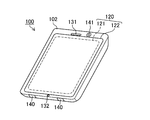
- FIG. 2 is an external view of a smartphone constituting the drug identification system shown in FIG.
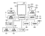
- FIG. 3 is a block diagram showing an internal configuration of the smartphone shown in FIG.
- FIG. 4 is a block diagram showing the electrical configuration of the drug identification system shown in FIG.
- FIG. 5 is a block diagram showing a hardware configuration of an image processing device including a machine learning device.
- FIG. 6 is a diagram showing an example of a learning data set stored in the database shown in FIG.
- FIG. 7 is a functional block diagram showing the functions of the machine learning device, which is a main component of the image processing device shown in FIG. FIG.
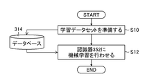
- FIG. 8 is a flowchart showing an embodiment of the image processing method according to the present invention, and in particular, is a diagram showing processing of a learning phase in a machine learning device.
- FIG. 9 is a flowchart showing an embodiment of the image processing method according to the present invention, and in particular, is a diagram showing processing of a drug recognition phase by a smartphone.
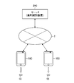
- FIG. 1 is a system configuration diagram showing an embodiment of a drug identification system including a mobile terminal according to the present invention.
- the drug identification system is composed of a smartphone 100 which is a mobile terminal with a camera and a server 200 which functions as a drug identification device.
- the smartphone 100 and the server 200 are connected to the Internet and a LAN (Local Area Network). Is connected so that data communication is possible via the network 2 such as.
- LAN Local Area Network
- the smartphone 100 has a camera unit, and the camera unit captures the drug 10 which is a recognition target.
- the smartphone 100 includes an image processing device according to the present invention that processes an image (third image) of the photographed drug 10, and displays an image (fourth image) after image processing by the image processing device on the display unit. Or, it is transmitted to the server 200 via the network 2. The details of the image processing device will be described later.
- the server 200 identifies the drug 10 based on the fourth image of the drug 10 uploaded from the smartphone 100, and outputs the identification result (for example, drug identification information consisting of a drug name, a product name, an abbreviation, or a combination thereof). ,
- the fourth image of the drug 10 is transmitted to the smartphone 100 that has transmitted the image.
- identification code information for identifying the type of drug is attached to the surface of the drug (tablet).
- This identification code information is generally attached by engraving or printing (printing).
- the server 200 can improve the discriminating power of the drug by using the identification code information attached to the drug.
- the engraving on the drug means that the identification code information is formed by forming a groove, which is a depressed region, on the surface of the drug.
- the groove is not limited to the one formed by digging the surface, and may be formed by pressing the surface. Further, the engraving may include a marking that does not have an identification function such as a score line.
- the printing attached to the drug means that the identification code information is formed by applying edible ink or the like to the surface of the drug in contact or non-contact.
- attachmented by printing is synonymous with “attached by printing.”
- the smartphone 100 shown in FIG. 2 has a flat-plate housing 102, and a display panel 121 as a display unit and an operation panel 122 as an input unit are integrally formed on one surface of the housing 102.
- Display unit 120 is provided.
- the display panel 121 is composed of a liquid crystal panel, and the display unit 120 of this example is a liquid crystal display.
- the housing 102 includes a speaker 131, a microphone 132, an operation unit 140, and a camera unit 141.
- the camera unit 141 includes at least one of a camera (in-camera) provided on the same surface side as the display unit 120 and a camera (out-camera (not shown)) provided on the surface side opposite to the display unit 120.
- FIG. 3 is a block diagram showing the internal configuration of the smartphone 100 shown in FIG.
- the smartphone 100 has, as main components, a wireless communication unit 110, a display unit 120, a call unit 130, an operation unit 140, a camera unit 141, a storage unit 150, and an external input / output unit. It includes 160 (image output unit), a GPS (global positioning system) receiving unit 170, a motion sensor unit 180, a power supply unit 190, and a main control unit 101. Further, as a main function of the smartphone 100, it is provided with a wireless communication function for performing mobile wireless communication via a base station device and a mobile communication network.
- a wireless communication function for performing mobile wireless communication via a base station device and a mobile communication network.
- the wireless communication unit 110 performs wireless communication with the base station device connected to the mobile communication network according to the instruction of the main control unit 101.
- the wireless communication is used to send and receive various file data such as voice data and image data, e-mail data, and receive web data and streaming data.
- the display unit 120 is a display with a so-called touch panel provided with an operation panel 122 arranged on the screen of the display panel 121, and displays images (still images and moving images), character information, and the like under the control of the main control unit 101.
- the information is visually transmitted to the user, and the user operation on the displayed information is detected.
- the display panel 121 uses an LCD (Liquid Crystal Display) as a display device.
- the display panel 121 is not limited to the LCD, and may be, for example, an OLED (organic light emission diode).
- the operation panel 122 is a device provided in a state in which an image displayed on the display surface of the display panel 121 can be visually recognized, and detects one or a plurality of coordinates operated by a user's finger or a stylus.
- the operation panel 122 outputs a detection signal generated due to the operation to the main control unit 101.
- the main control unit 101 detects the operation position (coordinates) on the display panel 121 based on the received detection signal.
- the call unit 130 includes a speaker 131 and a microphone 132, converts a user's voice input through the microphone 132 into voice data that can be processed by the main control unit 101, and outputs the data to the main control unit 101, or a wireless communication unit.
- the audio data received by the 110 or the external input / output unit 160 is decoded and output from the speaker 131.
- the operation unit 140 is a hardware key using a key switch or the like, and receives an instruction from the user.
- the operation unit 140 is mounted on the side surface of the housing 102 of the smartphone 100, and is switched on when pressed with a finger or the like, and switched off by a restoring force such as a spring when the finger is released. It is a push button type switch that is in a state.
- the storage unit 150 includes the control program and control data of the main control unit 101, address data associated with the name and telephone number of the communication partner, transmitted / received e-mail data, web data downloaded by web browsing, and downloaded contents. Data etc. are stored, and streaming data etc. are temporarily stored.
- the storage unit 150 is composed of an internal storage unit 151 and an external storage unit 152 having a detachable external memory slot.
- Each of the internal storage unit 151 and the external storage unit 152 constituting the storage unit 150 is a flash memory type, a hard disk type, a multimedia card micro type, a card type memory, a RAM (Random Access Memory), or a ROM (Read). It is realized by using a storage medium such as Only Memory).
- the external input / output unit 160 serves as an interface with all external devices connected to the smartphone 100, and is used for communication (for example, USB (Universal Serial Bus), IEEE 1394, etc.) or network (for example, wireless LAN (Local Area)). Connect directly or indirectly to other external devices via Network) or Bluetooth (registered trademark).
- USB Universal Serial Bus
- IEEE 1394 IEEE 1394
- network for example, wireless LAN (Local Area)
- Bluetooth registered trademark
- the GPS receiving unit 170 receives GPS signals transmitted from the GPS satellites ST1 and ST2 to STn according to the instruction of the main control unit 101, executes positioning calculation processing based on the received plurality of GPS signals, and executes positioning calculation processing based on the received GPS signals, and the latitude of the smartphone 100. , Acquires position information (GPS information) specified by longitude and altitude.
- GPS information position information specified by longitude and altitude.
- the GPS receiving unit 170 can acquire the position information from the wireless communication unit 110 and / or the external input / output unit 160 (for example, wireless LAN), the GPS receiving unit 170 can also detect the position using the position information.
- the motion sensor unit 180 includes, for example, a three-axis acceleration sensor, and detects the physical movement of the smartphone 100 according to the instruction of the main control unit 101. By detecting the physical movement of the smartphone 100, the moving direction and acceleration of the smartphone 100 are detected. The result of the detection is output to the main control unit 101.
- the power supply unit 190 supplies the electric power stored in the battery (not shown) to each unit of the smartphone 100 according to the instruction of the main control unit 101.
- the main control unit 101 includes a microprocessor, operates according to the control program and control data stored in the storage unit 150, and controls each part of the smartphone 100 in an integrated manner.
- the main control unit 101 includes a mobile communication control function that controls each unit of the communication system and a software processing function in order to perform voice communication and data communication through the wireless communication unit 110.
- the software processing function is realized by operating the main control unit 101 according to the software (program) stored in the storage unit 150.
- the software processing function includes, for example, an e-mail function for sending and receiving e-mail by controlling an external input / output unit 160, a web browsing function for browsing a web page, and an image processing device according to the present invention for the smartphone 100.
- the software that causes the smartphone 100 to function as the image processing device according to the present invention downloads the corresponding software from the server 200 that functions as the drug identification device or the site of the business operator that operates the server 200. By doing so, it can be installed on the smartphone 100.
- the main control unit 101 has an image processing function such as displaying an image on the display unit 120 based on image data (still image or moving image data) such as received data or downloaded streaming data.
- image data still image or moving image data
- the main control unit 101 executes display control for the display unit 120 and operation detection control for detecting a user operation through the operation unit 140 and the operation panel 122.
- the camera unit 141 converts the image data obtained by imaging into compressed image data such as JPEG (Joint Photographic Experts Group), and records the image data in the storage unit 150. It can be output through the external input / output unit 160 or the wireless communication unit 110.
- compressed image data such as JPEG (Joint Photographic Experts Group)
- the camera unit 141 can be used for various functions of the smartphone 100. In this example, when identifying a drug, it is used for photographing the drug. The image from the camera unit 141 can also be used in the software.
- FIG. 4 is a block diagram showing the electrical configuration of the drug identification system shown in FIG.
- a program (application) according to the present invention is installed in the smartphone 100, and the main control unit 101 of the smartphone 100 executes this application to execute the image extraction unit 101A, the recognizer 101B, and the image generation unit 101C. And functions as a communication control unit 101D.
- the camera unit 141 and the image extraction unit 101A function as an image input unit for inputting an image (third image) of the drug into the recognizer 101B.
- the photographed image of the drug photographed by the camera unit 141 is input to the main control unit 101.
- the image extraction unit of the main control unit 101 extracts a region corresponding to the drug, which is a recognition target, from the input captured image, and causes the recognizer 101B to input an image (drug image) of the extracted region.
- the drug image is preferably extracted (cut out) by detecting the outer shape of the drug and cutting out according to the outer shape of the drug. For example, a rectangular region inscribed by the outer shape of the drug can be cut out.
- the recognizer 101B can apply a convolutional neural network (CNN: Convolution Neural Network), which is one of the deep learning models.
- CNN Convolution Neural Network
- the recognizer 101B is a learning data set of a plurality of different drugs to which the marking or printing is added, and the image (first image) in which the marking or printing of the drug is not emphasized and the marking or printing of the drug are emphasized.
- Machine learning was performed using a learning data set for learning, which is a set of the image (second image).
- the recognizer 101B does not need to have a learning function by itself, and is configured as a learned model by acquiring the parameters of a model (CNN) in which machine learning is performed by an external machine learning device. It may be a new one.
- FIG. 5 is a block diagram showing a hardware configuration of an image processing device 300 including a machine learning device.
- the image processing device 300 shown in FIG. 5 a personal computer or a workstation can be used.
- the image processing device 300 of this example mainly includes an image input unit 312, a database 314, a storage unit 316, an operation unit 318, a CPU (Central Processing Unit) 320, a RAM (Random Access Memory) 322, and a ROM ( It is composed of a Read Only Memory) 324 and a display unit 326.
- a CPU Central Processing Unit
- RAM Random Access Memory
- ROM It is composed of a Read Only Memory 324 and a display unit 326.
- the image input unit 312 is a part for inputting an image of a recognition object (“drug” in this example) to which a stamp or print is added, and inputting a learning data set or the like to be stored in the database 314.
- Database 314 is a storage unit that stores the learning data set.
- FIG. 6 is a diagram showing an example of a learning data set stored in the database 314 shown in FIG.
- the learning data set is a set of images of a plurality of drugs of different types (first image 25) and an image in which the marking or printing of each drug corresponding to the first image 25 is emphasized (second image 27). ing.
- the first image 25 and the second image 27 are input images and correct answer data used during machine learning of the learning model, respectively.
- the first image 25 can be collected by photographing the drug. Generally, the marking in the first image 25 is not clearly shown.
- the second image 27 is an image showing the marking or printing of the drug.
- the second image 27 can be obtained by displaying the first image 25 on the display unit 326 and the user using the operation unit 318 to fill the engraved portion or the printed portion on the screen of the display unit 326.
- the second image is not limited to the one created manually, but uses an integrated image (an image with enhancement processing for emphasizing engraving or printing) generated by the drug recognition device described in Patent Document 1 and the like. can do. That is, as the second image 27, it is possible to use an image that has been subjected to an enhancement process that emphasizes the marking or printing added to the drug, based on a plurality of images of the drug having different illumination directions of the light on the drug. it can.
- FIG. 7 is a functional block diagram showing the functions of the machine learning device 350, which is a main component of the image processing device 300 shown in FIG. 5, and includes the CPU 320, the storage unit 316, the RAM 322, the ROM 324, and the like shown in FIG. It consists of hardware.
- the machine learning device 350 mainly includes a recognizer 352, a loss value calculation unit 354 and a parameter control unit 356 that function as a learning unit that causes the recognizer 352 to perform machine learning.
- the CNN model is applied to the recognizer 352 in this example.
- the recognizer 352 has a plurality of layer structures and holds a plurality of parameters.
- the recognizer 352 can change from an unlearned model to a trained model by updating the parameters from the initial values to the optimum values.
- the initial value of the parameter of the recognizer 352 may be an arbitrary value, or for example, the parameter of the trained model of the image system for classifying images may be applied. In the latter case, good machine learning can be performed with a relatively small number of training data sets by performing transfer learning using the learning data set shown in FIG.
- the recognizer 352 includes an input layer 352A, an intermediate layer 352B having a plurality of sets composed of a convolutional layer and a pooling layer, and an output layer 352C, and a plurality of "nodes” are connected by “edges” in each layer. It has a structure.
- the first image 25 of the learning data set (FIG. 6) is input to the input layer 352A as an input image.
- the intermediate layer 352B has a plurality of sets including a convolutional layer and a pooling layer as one set, and is a portion for extracting features from the first image 25 input from the input layer 352A.
- the convolutional layer filters nearby nodes in the previous layer (performs a convolutional operation using the filter) and acquires a "feature map".
- the pooling layer reduces the feature map output from the convolution layer to a new feature map.
- the "convolution layer” plays a role of feature extraction such as edge extraction from an image, and the "pooling layer” plays a role of imparting robustness so that the extracted features are not affected by translation or the like.
- the intermediate layer 352B is not limited to the case where the convolutional layer and the pooling layer are set as one set, but also includes the case where the convolutional layers are continuous and the normalization layer.
- the convolution layer in the final stage is a feature map (image) having the same size as the input image, and is a portion that outputs a feature map showing the features (engraving, etc.) of the drug.
- the output layer 352C is a portion that outputs the recognition result of the recognizer 352 (in this example, an image in which the marking or the like is emphasized).
- the loss value calculation unit 354 acquires the recognition result (output image) output from the output layer 352C of the recognizer 352 and the second image 27 (correct answer data) paired with the first image 25, and the loss between the two. Calculate the value.
- a method of calculating the loss value for example, a Jaccard coefficient or a dice coefficient can be used.
- the parameter control unit 356 minimizes or is similar to the distance between the correct answer data and the output of the recognizer 352 in the feature space by the error back propagation method based on the loss value calculated by the loss value calculation unit 354.
- the parameters of the recognizer 352 (such as the coefficient of the filter of each convolution layer) are adjusted in order to maximize the degree.
- the trained recognizer 352 uses an image of an arbitrary drug (third image) acquired by the image input unit 312 as an input image, recognizes the marking of the drug from the input image, and recognizes the recognition result (third). 4 images) is output to the image output unit 360.
- the recognizer 101B of the smartphone 100 acquires the same parameters as the parameters of the learned recognizer 352 from the machine learning device 350 shown in FIG. 7, and learns by setting the acquired parameters. It has the same recognition function as the existing recognizer 352.
- the image generation unit 101C is recognized by the recognizer 101B and the third image of the drug (the image of the drug to be recognized whose marking or printing is not emphasized) taken by the camera unit 141 and extracted by the image extraction unit 101A.
- the recognition result (fourth image) is combined to generate a composite image (fifth image) in which the marking or printing of the drug is emphasized.
- the fourth image is an image showing only the marking or printing of the drug, like the second image 27 shown in FIG. 6, and is an image having high brightness of the stamped portion or the printed portion. Therefore, the image generation unit 101C can generate a fifth image in which the engraved or printed portion of the drug is highlighted in black by subtracting the fourth image from the third image. In the case of a third image having low brightness (for example, an image obtained by photographing a black drug), the image generation unit 101C adds the fourth image to the third image to emphasize the stamped or printed portion of the drug in white. The fifth image can be generated.
- the display control unit (not shown) that functions as an image output unit outputs the recognition result (fourth image) by the recognizer 101B or the fifth image including the fourth image to the display unit 120 and displays it on the display unit 120. Let me.
- the user can display the fourth image or the fifth image on the display unit 120 of the smartphone 100 by photographing the drug with the smartphone 100, and is added to the drug by the fourth image or the fifth image.
- the engraving or printing can be easily visually recognized.
- the recognition result (fourth image) by the recognizer 101B or the fifth image including the fourth image emphasizes the marking or printing added to the drug, and is therefore suitable for discriminating or auditing the drug. Is.
- the communication control unit 101D and the wireless communication unit 110 which function as image output units, transmit the recognition result (fourth image) by the recognizer 101B or the fifth image including the fourth image to the server via the network 2. It is transmitted to the 200, and the identification result of the drug to be identified, which is identified by the server 200 based on the fourth image or the fifth image, is acquired via the network 2.
- the server 200 shown in FIG. 4 functions as a drug identification device, and is mainly composed of a communication unit 210, a CPU (Central Processing Unit) 220, a drug DB (database) 230, a memory 240, and a drug identification unit 250. There is.
- the CPU 220 is a part that controls each part of the server 200, and functions the communication unit 210 as an image receiving unit that receives the fourth image or the fifth image of the drug transmitted from the smartphone 100, and receives the fourth image or the fourth image.
- the drug identification unit 250 executes the drug identification process based on the image.
- the drug DB 230 is a part for registering and managing drug images (drug images on the front side and back side of the drug) in association with drug identification information such as the name of the drug.
- the drug image of the drug (registered drug) registered in the drug DB 230 is used as a template image for identifying which of the registered drugs the registered drug corresponds to the drug to be identified.
- the memory 240 includes a storage unit in which a program for providing a drug identification service is stored, and a portion serving as a work area of the CPU 220.
- the drug identification unit 250 performs template matching between the image (fourth image or fifth image) of the drug to be identified received via the communication unit 210 and the template image of the registered drug registered in the drug DB 230, and matches them. Acquire identification results such as drug identification information (including images of registered drugs) of the registered drug having the maximum degree or a plurality of registered drugs having a high degree of matching.
- the CPU 220 transmits the drug identification result by the drug identification unit 250 to the smartphone 100 that transmitted the fourth image or the fifth image via the communication unit 210.
- the server 200 is provided with the function of the smartphone 100 that generates the fourth image or the fifth image, the fourth image or the fifth image generated by the server 200 is transmitted to the smartphone 100, and the identification result of the drug is transmitted to the smartphone. It may be sent to 100.
- the smartphone 100 captures an image of the drug to be identified and transmits the captured drug image to the server 200 as it is, thereby acquiring or capturing an image in which the engraving or printing is emphasized from the server 200.
- the drug recognition result can be obtained from the server 200.
- ⁇ Image processing method> 8 and 9 are flowcharts showing embodiments of the image processing method according to the present invention, respectively.
- FIG. 8 shows the processing of the learning phase in the machine learning device 350 shown in FIG. 7.
- a learning data set of a plurality of different drugs with engraving or printing is prepared (step S10).
- the learning data set is a learning data set for machine learning that includes a first image 25 in which the marking or printing is not emphasized and a second image 27 in which the marking or printing is emphasized as shown in FIG. Yes, it is stored in database 314 (FIG. 5).
- the machine learning device 350 causes the recognizer 352 to perform machine learning using the learning data set stored in the database 314 (step S12).
- FIG. 9 shows the processing of the drug recognition phase by the smartphone 100 shown in FIG. 4 and the like.
- the smartphone 100 of this example includes a recognizer 101B in which the same parameters as those of the learned recognizer 252 are set.
- the recognizer 101B has the same recognition function as the learned recognizer 252.
- an image (third image) of an arbitrary recognition target drug to which a stamp or print is added from the image input unit is input to the recognizer 101B as an input image (step S20). That is, the drug to be recognized is photographed by the camera unit 141 that functions as an image input unit, an image (drug image) of the region corresponding to the drug is extracted from the captured image, and the extracted drug image (third image) is used as a recognizer. Let 101B input.
- the recognizer 101B outputs an image (fourth image) showing the marking or printing added to the drug to be recognized as the recognition result for the input third image (step S22).
- the image generation unit 101C synthesizes the third image (drug image) and the fourth image output from the recognizer 101B, and generates a composite image (fifth image) in which the marking or printing of the drug is emphasized (step). S24).
- the display control unit that functions as an image output unit outputs the fifth image generated in step S24 to the display unit 120, and causes the display unit 120 to display the fifth image in which the marking or printing of the drug to be recognized is emphasized. (Step S26).
- the user can display the fifth image on the display unit 120 of the smartphone 100 by photographing the drug with the smartphone 100, and easily visually recognizes the marking or printing added to the drug by the fifth image. be able to.
- the communication control unit 101D and the wireless communication unit 110 that function as the image output unit transmit the fifth image generated in step S24 to the server 200 via the network 2 (step S28).
- the server 200 acquires identification results such as drug identification information such as the name of the drug to be recognized based on the fifth image, transmits the acquired identification results to the smartphone 100, and the smartphone 100 identifies the drug from the server 200. Receive the result (step S30).
- the display control unit of the smartphone 100 outputs the drug identification result received from the server 200 to the display unit 120, and displays the drug identification result on the display unit 120 (step S32).
- the user can display the identification result such as the drug name of the drug on the display unit 120 of the smartphone 100 by photographing the drug with the smartphone 100.
- the image processing device of the present embodiment can be incorporated into a drug recognition device, whereby the drug recognition device can be miniaturized and inexpensive.
- the mobile terminal according to the present invention is not limited to a smartphone, but may be a tablet terminal having a camera function, a mobile phone, a PDA (Personal Digital Assistants), or the like.
- the drug is used as a recognition object, but the present invention is not limited to this, and the present invention can be applied to the recognition of other recognition objects such as metal parts with engravings and precious metals.
- processors include CPU (Central Processing Unit), GPU (Graphics Processing Unit), FPGA (Field Programmable Gate Array), which are general-purpose processors that execute programs and function as various processing units.
- CPU Central Processing Unit
- GPU Graphics Processing Unit
- FPGA Field Programmable Gate Array
- a dedicated electric circuit that is a processor having a circuit configuration specially designed to execute a specific process such as a programmable logic device (PLD) or an ASIC (Application Specific Integrated Circuit), which is a processor that can change the CPU. Etc. are included.
- One processing unit constituting the image processing device may be composed of one of the above-mentioned various processors, or may be composed of two or more processors of the same type or different types.
- one processing unit may be composed of a plurality of FPGAs or a combination of a CPU and an FPGA.
- a plurality of processing units may be configured by one processor.
- a processor As an example of configuring a plurality of processing units with one processor, first, as represented by a computer such as a client or a server, one processor is configured by a combination of one or more CPUs and software. There is a form in which this processor functions as a plurality of processing units.
- SoC System On Chip
- SoC System On Chip
- the various processing units are configured by using one or more of the above-mentioned various processors as a hardware structure.
- the hardware structure of these various processors is, more specifically, an electric circuit (circuitry) in which circuit elements such as semiconductor elements are combined.
- the present invention includes a program that causes the computer to function as an image processing device according to the present invention by being installed in the computer, and a storage medium in which this program is recorded.
Landscapes
- Engineering & Computer Science (AREA)
- Theoretical Computer Science (AREA)
- Data Mining & Analysis (AREA)
- Bioinformatics & Cheminformatics (AREA)
- Bioinformatics & Computational Biology (AREA)
- Computer Vision & Pattern Recognition (AREA)
- Life Sciences & Earth Sciences (AREA)
- Evolutionary Biology (AREA)
- Evolutionary Computation (AREA)
- Physics & Mathematics (AREA)
- General Engineering & Computer Science (AREA)
- General Physics & Mathematics (AREA)
- Artificial Intelligence (AREA)
- Image Analysis (AREA)
- Image Processing (AREA)
Abstract
Provided are an image processing device, a portable terminal, an image processing method, and a program with which it is possible to easily acquire an image in which the marking or printing added to an object to be recognized is emphasized. A smartphone (100) comprises: a recognizer (101B) that has been trained by machine learning using a learning dataset for learning for a plurality of different medicines that have been marked or printed on, a set being formed by a first medicine image in which the marking or printing is not emphasized and a second medicine image in which the marking or printing is emphasized; a camera unit (141) functioning as an image input unit for inputting, to the recognizer (101B), a third image which is an image of a discretionary medicine that has been marked or printed on and in which the marking or printing is not emphasized; and an image output unit for outputting the recognition result obtained from the recognizer (101B) to a display unit (120) when the third image has been inputted to the recognizer (101B).
Description
本発明は画像処理装置、携帯端末、画像処理方法及びプログラムに係り、特に認識対象物に付加された刻印又は印字を認識する技術に関する。
The present invention relates to an image processing device, a mobile terminal, an image processing method and a program, and particularly relates to a technique for recognizing a stamp or print added to a recognition object.
従来、刻印が付加された薬剤の種類を正確に認識することができる薬剤認識装置が提案されている(特許文献1)。
Conventionally, a drug recognition device capable of accurately recognizing the type of drug with a stamp has been proposed (Patent Document 1).
特許文献1に記載の薬剤認識装置は、刻印が付加された薬剤に対して薬剤の周囲を囲む複数の照明方向から照明可能な照明部が、薬剤を照明する照明方向を順番に切り替える。撮影部により、照明部の照明方向が切り替わる毎に薬剤の撮影を繰り返し行う。特徴画像抽出部が、撮影部により取得された照明方向毎の撮影画像(薬剤画像)を解析して、薬剤画像毎に刻印の影に対応する特徴画像を抽出する。特徴画像統合部が、特徴画像抽出部により抽出された照明方向毎の特徴画像を統合して統合画像を生成する。認識部が、特徴画像統合部により生成された統合画像に含まれる刻印を認識して、刻印の認識結果に基づき薬剤の種類を認識する。
In the drug recognition device described in Patent Document 1, the lighting unit capable of illuminating the engraved drug from a plurality of lighting directions surrounding the drug switches the lighting direction for illuminating the drug in order. The imaging unit repeatedly photographs the drug each time the illumination direction of the illumination unit is switched. The feature image extraction unit analyzes the captured image (drug image) for each illumination direction acquired by the photographing unit, and extracts the feature image corresponding to the shadow of the engraving for each drug image. The feature image integration unit integrates the feature images for each illumination direction extracted by the feature image extraction unit to generate an integrated image. The recognition unit recognizes the marking included in the integrated image generated by the feature image integration unit, and recognizes the type of the drug based on the recognition result of the marking.
特許文献1に記載の薬剤認識装置は、刻印が強調された統合画像を取得することができるが、薬剤に対する照明方向がそれぞれ異なる複数の照明部を必要とするため、装置が大型化する。
The drug recognition device described in Patent Document 1 can acquire an integrated image in which the engraving is emphasized, but the device becomes large because it requires a plurality of lighting units having different illumination directions for the drug.
また、特許文献1に記載の薬剤認識装置は、複数の照明部を順次点灯し、照明方向毎の薬剤画像を、時間をずらして複数回撮影するため、撮影時間が長くなる。更に複数回の撮影中に薬剤が移動するおそれがあり、この場合には良好な統合画像が生成できなくなるという問題がある。
Further, in the drug recognition device described in Patent Document 1, a plurality of lighting units are sequentially turned on, and drug images for each illumination direction are photographed a plurality of times at different times, so that the photographing time becomes long. Further, there is a possibility that the drug may move during a plurality of shootings, and in this case, there is a problem that a good integrated image cannot be generated.
本発明はこのような事情に鑑みてなされたもので、認識対象物に付加された刻印又は印字が強調された画像を簡単に取得することができる画像処理装置、携帯端末、画像処理方法及びプログラムを提供することを目的とする。
The present invention has been made in view of such circumstances, and is an image processing device, a mobile terminal, an image processing method, and a program capable of easily acquiring an image in which the marking or printing emphasized on the recognition object is emphasized. The purpose is to provide.
上記目的を達成するために本発明の一の態様に係る画像処理装置は、刻印又は印字が付加された複数の異なる認識対象物の学習データセットであって、認識対象物の刻印又は印字が強調されていない第1画像と刻印又は印字が強調された第2画像とをセットとする学習用の学習データセットにより機械学習が行われた認識器と、刻印又は印字が付加された任意の認識対象物の画像であって、刻印又は印字が強調されていない第3画像を認識器に入力させる画像入力部と、第3画像が認識器に入力された場合に認識器から得られる認識結果を出力する画像出力部と、を備える。
In order to achieve the above object, the image processing apparatus according to one aspect of the present invention is a learning data set of a plurality of different recognition objects to which marking or printing is added, and the marking or printing of the recognition target is emphasized. A recognizer that has been machine-learned by a learning data set for learning, which is a set of an unmarked first image and a second image with embossed or printed emphasis, and an arbitrary recognition target with engraved or printed images. An image input unit that causes the recognizer to input a third image that is an image of an object and whose marking or printing is not emphasized, and outputs a recognition result obtained from the recognizer when the third image is input to the recognizer. An image output unit is provided.
本発明の一の態様によれば、上記の学習データセットにより機械学習が行われた認識器を構築することで、刻印又は印字が付加された任意の認識対象物の画像を認識器に入力すると、その刻印又は印字を示す認識結果を出力することができる。
According to one aspect of the present invention, by constructing a recognizer in which machine learning is performed by the above learning data set, an image of an arbitrary recognition object to which an engraving or printing is added is input to the recognizer. , The recognition result indicating the marking or printing can be output.
本発明の他の態様に係る画像処理装置において、認識結果は、任意の認識対象物に付加された刻印又は印字が強調された第4画像である。
In the image processing apparatus according to another aspect of the present invention, the recognition result is a fourth image in which the marking or printing added to an arbitrary recognition object is emphasized.
本発明の更に他の態様に係る画像処理装置において、第3画像と第4画像とを合成し、刻印又は印字が強調された第5画像を生成する画像生成部を備えることが好ましい。
In the image processing apparatus according to still another aspect of the present invention, it is preferable to include an image generation unit that combines a third image and a fourth image to generate a fifth image in which engraving or printing is emphasized.
本発明の更に他の態様に係る画像処理装置において、画像出力部は、認識結果を表示部に出力し、認識結果を表示部に表示させることが好ましい。
In the image processing apparatus according to still another aspect of the present invention, it is preferable that the image output unit outputs the recognition result to the display unit and displays the recognition result on the display unit.
本発明の更に他の態様に係る画像処理装置において、認識対象物は薬剤である。
In the image processing apparatus according to still another aspect of the present invention, the recognition target is a drug.
本発明の更に他の態様に係る画像処理装置において、画像出力部は、認識結果を薬剤認識装置に出力することが好ましい。
In the image processing device according to still another aspect of the present invention, it is preferable that the image output unit outputs the recognition result to the drug recognition device.
本発明の更に他の態様に係る画像処理装置において、認識器は、学習データセットの第1画像を入力画像とし、第2画像を出力画像として機械学習を行った畳み込みニューラルネットワークで構成されることが好ましい。
In the image processing apparatus according to still another aspect of the present invention, the recognizer is composed of a convolutional neural network in which the first image of the training data set is used as an input image and the second image is used as an output image for machine learning. Is preferable.
本発明の更に他の態様に係る画像処理装置において、学習データセットに含まれる第2画像は、認識対象物への光の照明方向がそれぞれ異なる認識対象物の複数の画像に基づいて、認識対象物に付加された刻印又は印字を強調する強調処理が施された画像を含むことが好ましい。
In the image processing apparatus according to still another aspect of the present invention, the second image included in the training data set is a recognition target based on a plurality of images of the recognition target having different illumination directions of light on the recognition target. It is preferable to include an image that has been subjected to an enhancement process that emphasizes the marking or printing added to the object.
本発明の更に他の態様に係る画像処理装置において、画像入力部は、任意の認識対象物を含む画像を撮影するカメラ部と、カメラ部により撮影された撮影画像から認識対象物に対応する領域を抽出する画像抽出部とを含み、画像抽出部により抽出した画像を第3画像として認識器に入力させることが好ましい。
In the image processing apparatus according to still another aspect of the present invention, the image input unit includes a camera unit that captures an image including an arbitrary recognition object, and a region corresponding to the recognition object from the captured image captured by the camera unit. It is preferable to include an image extraction unit for extracting the image and input the image extracted by the image extraction unit to the recognizer as a third image.
更に他の態様に係る発明は、上記の画像処理装置を備えた携帯端末である。
The invention according to still another aspect is a mobile terminal provided with the above-mentioned image processing device.
本発明の更に他の態様に係る画像処理方法は、刻印又は印字が付加された複数の異なる認識対象物の学習データセットであって、認識対象物の刻印又は印字が強調されていない第1画像と刻印又は印字が強調された第2画像とをセットとする学習用の学習データセットを準備するステップと、学習データセットにより認識器に機械学習を行わせるステップと、刻印又は印字が付加された任意の認識対象物の画像であって、刻印又は印字が強調されていない第3画像を、機械学習が行われた認識器に入力させるステップと、画像出力部が、第3画像が認識器に入力された場合に認識器から得られる認識結果を出力するステップと、を含む。
The image processing method according to still another aspect of the present invention is a learning data set of a plurality of different recognition objects to which marking or printing is added, and the marking or printing of the recognition target is not emphasized. A step of preparing a learning data set for learning, which is a set of a second image in which the marking or printing is emphasized, a step of causing the recognizer to perform machine learning by the learning data set, and a step of marking or printing are added. A step of inputting a third image, which is an image of an arbitrary recognition object and whose marking or printing is not emphasized, to a machine-learned recognizer, and an image output unit, the third image is sent to the recognizer. Includes a step to output the recognition result obtained from the recognizer when input.
本発明の更に他の態様に係る画像処理方法において、認識結果は、任意の認識対象物に付加された刻印又は印字が強調された第4画像であることが好ましい。
In the image processing method according to still another aspect of the present invention, it is preferable that the recognition result is a fourth image in which the marking or printing added to an arbitrary recognition object is emphasized.
本発明の更に他の態様に係る画像処理方法において、画像生成部が、第3画像と第4画像とを合成し、刻印又は印字が強調された第5画像を生成するステップを含むことが好ましい。
In the image processing method according to still another aspect of the present invention, it is preferable that the image generation unit includes a step of synthesizing the third image and the fourth image to generate a fifth image in which the marking or printing is emphasized. ..
本発明の更に他の態様に係る画像処理方法において、認識結果を出力するステップは、認識結果を表示部に出力し、認識結果を表示部に表示させることが好ましい。
In the image processing method according to still another aspect of the present invention, it is preferable that the step of outputting the recognition result is to output the recognition result to the display unit and display the recognition result on the display unit.
本発明の更に他の態様に係る画像処理方法において、認識対象物は薬剤である。
In the image processing method according to still another aspect of the present invention, the object to be recognized is a drug.
本発明の更に他の態様に係る画像処理方法において、認識結果を出力するステップは、認識結果を薬剤認識装置に出力することが好ましい。
In the image processing method according to still another aspect of the present invention, it is preferable that the recognition result is output to the drug recognition device in the step of outputting the recognition result.
本発明の更に他の態様に係る画像処理方法において、学習データセットに含まれる第2画像は、認識対象物への光の照明方向がそれぞれ異なる認識対象物の複数の画像に基づいて、認識対象物に付加された刻印又は印字を強調する強調処理が施された画像を含むことが好ましい。
In the image processing method according to still another aspect of the present invention, the second image included in the training data set is a recognition target based on a plurality of images of the recognition target having different illumination directions of light on the recognition target. It is preferable to include an image that has been subjected to an enhancement process that emphasizes the marking or printing added to the object.
本発明の更に他の態様に係るプログラムは、コンピュータにインストールされることにより、そのコンピュータを上記の画像処理装置として機能させる。
The program according to still another aspect of the present invention is installed in a computer to make the computer function as the above-mentioned image processing device.
本発明によれば、認識対象物に付加された刻印又は印字が強調された画像を簡単に取得することができる。
According to the present invention, it is possible to easily obtain an image in which the engraving or printing added to the recognition object is emphasized.
以下、添付図面に従って本発明に係る画像処理装置、携帯端末、画像処理方法及びプログラムの好ましい実施形態について説明する。
Hereinafter, preferred embodiments of the image processing apparatus, mobile terminal, image processing method, and program according to the present invention will be described with reference to the accompanying drawings.
[薬剤識別システムの構成]
図1は、本発明に係る携帯端末を含む薬剤識別システムの実施形態を示すシステム構成図である。 [Drug identification system configuration]
FIG. 1 is a system configuration diagram showing an embodiment of a drug identification system including a mobile terminal according to the present invention.
図1は、本発明に係る携帯端末を含む薬剤識別システムの実施形態を示すシステム構成図である。 [Drug identification system configuration]
FIG. 1 is a system configuration diagram showing an embodiment of a drug identification system including a mobile terminal according to the present invention.
図1に示すように、薬剤識別システムは、カメラ付き携帯端末であるスマートフォン100と、薬剤識別装置として機能するサーバ200とから構成され、スマートフォン100とサーバ200とはインターネット、LAN(Local Area Network)等のネットワーク2を介してデータ通信可能に接続されている。
As shown in FIG. 1, the drug identification system is composed of a smartphone 100 which is a mobile terminal with a camera and a server 200 which functions as a drug identification device. The smartphone 100 and the server 200 are connected to the Internet and a LAN (Local Area Network). Is connected so that data communication is possible via the network 2 such as.
スマートフォン100は、カメラ部を有し、カメラ部により認識対象物である薬剤10を撮影する。スマートフォン100は、撮影した薬剤10の画像(第3画像)を処理する、本発明に係る画像処理装置を備え、その画像処理装置による画像処理後の画像(第4画像)を表示部に表示し、又はネットワーク2を介してサーバ200に送信する。尚、画像処理装置の詳細については後述する。
The smartphone 100 has a camera unit, and the camera unit captures the drug 10 which is a recognition target. The smartphone 100 includes an image processing device according to the present invention that processes an image (third image) of the photographed drug 10, and displays an image (fourth image) after image processing by the image processing device on the display unit. Or, it is transmitted to the server 200 via the network 2. The details of the image processing device will be described later.
サーバ200は、スマートフォン100からアップロードされた薬剤10の第4画像に基づいて薬剤10の識別を行い、その識別結果(例えば、薬剤名、商品名、略称又はこれらの組合せからなる薬剤識別情報)を、薬剤10の第4画像を送信したスマートフォン100に送信する。
The server 200 identifies the drug 10 based on the fourth image of the drug 10 uploaded from the smartphone 100, and outputs the identification result (for example, drug identification information consisting of a drug name, a product name, an abbreviation, or a combination thereof). , The fourth image of the drug 10 is transmitted to the smartphone 100 that has transmitted the image.
ところで、薬剤(錠剤)の表面には、薬剤の種別を識別するための識別コード情報が付されている。この識別コード情報は、一般に、刻印又は印字(印刷)によって付される。
By the way, identification code information for identifying the type of drug is attached to the surface of the drug (tablet). This identification code information is generally attached by engraving or printing (printing).
サーバ200は、薬剤に付された識別コード情報を利用することで、薬剤の識別力を向上させることができる。
The server 200 can improve the discriminating power of the drug by using the identification code information attached to the drug.
尚、薬剤に付された刻印とは、薬剤の表面に陥没領域である溝を形成することによって識別コード情報が形成されたものをいう。溝は、表面を掘って形成されたものに限定されず、表面を押圧することで形成されたものでもよい。また、刻印は、割線等の識別機能を伴わないものを含んでもよい。
The engraving on the drug means that the identification code information is formed by forming a groove, which is a depressed region, on the surface of the drug. The groove is not limited to the one formed by digging the surface, and may be formed by pressing the surface. Further, the engraving may include a marking that does not have an identification function such as a score line.
また、薬剤に付された印字とは、薬剤の表面に接触又は非接触で可食性インク等を付与することによって識別コード情報が形成されたものをいう。ここでは、印字によって付されたとは、印刷によって付されたと同義である。
Further, the printing attached to the drug means that the identification code information is formed by applying edible ink or the like to the surface of the drug in contact or non-contact. Here, "attached by printing" is synonymous with "attached by printing."
<スマートフォンの構成>
図2に示すスマートフォン100は、平板状の筐体102を有し、筐体102の一方の面に表示部としての表示パネル121と、入力部としての操作パネル122とが一体となって形成される表示部120が設けられる。表示パネル121は液晶パネルから構成されており、本例の表示部120は液晶ディスプレイである。 <Smartphone configuration>
Thesmartphone 100 shown in FIG. 2 has a flat-plate housing 102, and a display panel 121 as a display unit and an operation panel 122 as an input unit are integrally formed on one surface of the housing 102. Display unit 120 is provided. The display panel 121 is composed of a liquid crystal panel, and the display unit 120 of this example is a liquid crystal display.
図2に示すスマートフォン100は、平板状の筐体102を有し、筐体102の一方の面に表示部としての表示パネル121と、入力部としての操作パネル122とが一体となって形成される表示部120が設けられる。表示パネル121は液晶パネルから構成されており、本例の表示部120は液晶ディスプレイである。 <Smartphone configuration>
The
また、その筐体102は、スピーカ131と、マイクロホン132と、操作部140と、カメラ部141とを備える。カメラ部141は、表示部120と同じ面側に設けられたカメラ(インカメラ)と、表示部120と反対の面側に設けられたカメラ(図示しないアウトカメラ)のうちの少なくとも一方を含む。
Further, the housing 102 includes a speaker 131, a microphone 132, an operation unit 140, and a camera unit 141. The camera unit 141 includes at least one of a camera (in-camera) provided on the same surface side as the display unit 120 and a camera (out-camera (not shown)) provided on the surface side opposite to the display unit 120.
図3は、図2に示したスマートフォン100の内部構成を示すブロック図である。
FIG. 3 is a block diagram showing the internal configuration of the smartphone 100 shown in FIG.
図3に示すようにスマートフォン100は、主たる構成要素として、無線通信部110と、表示部120と、通話部130と、操作部140と、カメラ部141と、記憶部150と、外部入出力部160(画像出力部)と、GPS(global positioning system)受信部170と、モーションセンサ部180と、電源部190と、主制御部101とを備える。また、スマートフォン100の主たる機能として、基地局装置と移動通信網とを介した移動無線通信を行う無線通信機能を備える。
As shown in FIG. 3, the smartphone 100 has, as main components, a wireless communication unit 110, a display unit 120, a call unit 130, an operation unit 140, a camera unit 141, a storage unit 150, and an external input / output unit. It includes 160 (image output unit), a GPS (global positioning system) receiving unit 170, a motion sensor unit 180, a power supply unit 190, and a main control unit 101. Further, as a main function of the smartphone 100, it is provided with a wireless communication function for performing mobile wireless communication via a base station device and a mobile communication network.
無線通信部110は、主制御部101の指示に従って、移動通信網に接続された基地局装置との間で無線通信を行う。その無線通信が使用されて、音声データ及び画像データ等の各種ファイルデータや電子メールデータなどの送受信、及びウェブデータやストリーミングデータなどの受信が行われる。
The wireless communication unit 110 performs wireless communication with the base station device connected to the mobile communication network according to the instruction of the main control unit 101. The wireless communication is used to send and receive various file data such as voice data and image data, e-mail data, and receive web data and streaming data.
表示部120は、表示パネル121の画面上に配設された操作パネル122を備えたいわゆるタッチパネル付きディスプレイであり、主制御部101の制御により、画像(静止画及び動画)や文字情報などを表示して視覚的にユーザに情報を伝達し、また表示した情報に対するユーザ操作を検出する。
The display unit 120 is a display with a so-called touch panel provided with an operation panel 122 arranged on the screen of the display panel 121, and displays images (still images and moving images), character information, and the like under the control of the main control unit 101. The information is visually transmitted to the user, and the user operation on the displayed information is detected.
表示パネル121は、LCD(Liquid Crystal Display)を表示デバイスとして用いる。尚、表示パネル121は、LCDに限らず、例えば、OLED(organic light emitting diode)でもよい。
The display panel 121 uses an LCD (Liquid Crystal Display) as a display device. The display panel 121 is not limited to the LCD, and may be, for example, an OLED (organic light emission diode).
操作パネル122は、表示パネル121の表示面上に表示される画像が視認可能な状態で設けられ、ユーザの指や尖筆によって操作される1又は複数の座標を検出するデバイスである。そのデバイスがユーザの指や尖筆によって操作されると、操作パネル122は、操作に起因して発生する検出信号を主制御部101に出力する。次いで、主制御部101は、受信した検出信号に基づいて、表示パネル121上の操作位置(座標)を検出する。
The operation panel 122 is a device provided in a state in which an image displayed on the display surface of the display panel 121 can be visually recognized, and detects one or a plurality of coordinates operated by a user's finger or a stylus. When the device is operated by the user's finger or stylus, the operation panel 122 outputs a detection signal generated due to the operation to the main control unit 101. Next, the main control unit 101 detects the operation position (coordinates) on the display panel 121 based on the received detection signal.
通話部130は、スピーカ131及びマイクロホン132を備え、マイクロホン132を通じて入力されたユーザの音声を主制御部101にて処理可能な音声データに変換して主制御部101に出力したり、無線通信部110或いは外部入出力部160により受信された音声データを復号してスピーカ131から出力したりする。
The call unit 130 includes a speaker 131 and a microphone 132, converts a user's voice input through the microphone 132 into voice data that can be processed by the main control unit 101, and outputs the data to the main control unit 101, or a wireless communication unit. The audio data received by the 110 or the external input / output unit 160 is decoded and output from the speaker 131.
操作部140は、キースイッチなどを用いたハードウエアキーであって、ユーザからの指示を受け付ける。例えば、図2に示すように、操作部140は、スマートフォン100の筐体102の側面に搭載され、指などで押下されるとスイッチオン状態となり、指を離すとバネなどの復元力によってスイッチオフ状態となる押しボタン式のスイッチである。
The operation unit 140 is a hardware key using a key switch or the like, and receives an instruction from the user. For example, as shown in FIG. 2, the operation unit 140 is mounted on the side surface of the housing 102 of the smartphone 100, and is switched on when pressed with a finger or the like, and switched off by a restoring force such as a spring when the finger is released. It is a push button type switch that is in a state.
記憶部150は、主制御部101の制御プログラムや制御データ、通信相手の名称や電話番号などを対応づけたアドレスデータ、送受信した電子メールのデータ、ウェブブラウジングによりダウンロードしたウェブデータ、及びダウンロードしたコンテンツデータ等を記憶し、またストリーミングデータなどを一時的に記憶する。
The storage unit 150 includes the control program and control data of the main control unit 101, address data associated with the name and telephone number of the communication partner, transmitted / received e-mail data, web data downloaded by web browsing, and downloaded contents. Data etc. are stored, and streaming data etc. are temporarily stored.
また、記憶部150は、内部記憶部151と着脱自在な外部メモリスロットを有する外部記憶部152とにより構成される。尚、記憶部150を構成する内部記憶部151及び外部記憶部152のそれぞれは、フラッシュメモリタイプ、ハードディスクタイプ、マルチメディアカードマイクロタイプ、カードタイプのメモリ、RAM(Random Access Memory)、或いはROM(Read Only Memory)などの格納媒体を用いて実現される。
Further, the storage unit 150 is composed of an internal storage unit 151 and an external storage unit 152 having a detachable external memory slot. Each of the internal storage unit 151 and the external storage unit 152 constituting the storage unit 150 is a flash memory type, a hard disk type, a multimedia card micro type, a card type memory, a RAM (Random Access Memory), or a ROM (Read). It is realized by using a storage medium such as Only Memory).
外部入出力部160は、スマートフォン100に連結される全ての外部機器とのインターフェースの役割を果たし、通信等(例えば、USB(Universal Serial Bus)、IEEE1394など)又はネットワーク(例えば、無線LAN(Local Area Network)、ブルートゥース(Bluetooth)(登録商標)により他の外部機器に直接的又は間接的に接続する。
The external input / output unit 160 serves as an interface with all external devices connected to the smartphone 100, and is used for communication (for example, USB (Universal Serial Bus), IEEE 1394, etc.) or network (for example, wireless LAN (Local Area)). Connect directly or indirectly to other external devices via Network) or Bluetooth (registered trademark).
GPS受信部170は、主制御部101の指示に従って、GPS衛星ST1、ST2~STnから送信されるGPS信号を受信し、受信した複数のGPS信号に基づく測位演算処理を実行し、スマートフォン100の緯度、経度及び高度によって特定される位置情報(GPS情報)を取得する。GPS受信部170は、無線通信部110及び/又は外部入出力部160(例えば、無線LAN)から位置情報を取得できる場合には、その位置情報を用いて位置を検出することもできる。
The GPS receiving unit 170 receives GPS signals transmitted from the GPS satellites ST1 and ST2 to STn according to the instruction of the main control unit 101, executes positioning calculation processing based on the received plurality of GPS signals, and executes positioning calculation processing based on the received GPS signals, and the latitude of the smartphone 100. , Acquires position information (GPS information) specified by longitude and altitude. When the GPS receiving unit 170 can acquire the position information from the wireless communication unit 110 and / or the external input / output unit 160 (for example, wireless LAN), the GPS receiving unit 170 can also detect the position using the position information.
モーションセンサ部180は、例えば、3軸の加速度センサなどを備え、主制御部101の指示に従って、スマートフォン100の物理的な動きを検出する。スマートフォン100の物理的な動きを検出することにより、スマートフォン100の動く方向や加速度が検出される。その検出の結果は、主制御部101に出力される。
The motion sensor unit 180 includes, for example, a three-axis acceleration sensor, and detects the physical movement of the smartphone 100 according to the instruction of the main control unit 101. By detecting the physical movement of the smartphone 100, the moving direction and acceleration of the smartphone 100 are detected. The result of the detection is output to the main control unit 101.
電源部190は、主制御部101の指示に従って、スマートフォン100の各部に、バッテリ(図示しない)に蓄えられる電力を供給する。
The power supply unit 190 supplies the electric power stored in the battery (not shown) to each unit of the smartphone 100 according to the instruction of the main control unit 101.
主制御部101は、マイクロプロセッサを備え、記憶部150が記憶する制御プログラムや制御データに従って動作し、スマートフォン100の各部を統括して制御する。また、主制御部101は、無線通信部110を通じて音声通信及びデータ通信を行うために、通信系の各部を制御する移動通信制御機能と、ソフトウエア処理機能とを備える。
The main control unit 101 includes a microprocessor, operates according to the control program and control data stored in the storage unit 150, and controls each part of the smartphone 100 in an integrated manner. In addition, the main control unit 101 includes a mobile communication control function that controls each unit of the communication system and a software processing function in order to perform voice communication and data communication through the wireless communication unit 110.
ソフトウエア処理機能は、記憶部150が記憶するソフトウエア(プログラム)に従って主制御部101が動作することにより実現される。ソフトウエア処理機能は、例えば、外部入出力部160を制御することで電子メールの送受信を行う電子メール機能、及びウェブページを閲覧するウェブブラウジング機能の他、スマートフォン100を本発明に係る画像処理装置として機能させる。スマートフォン100を本発明に係る画像処理装置として機能させるソフトウエア(本発明に係るプログラム)は、薬剤識別装置として機能するサーバ200又はサーバ200を運営する事業者のサイト等から対応するソフトウエアをダウンロードすることによりスマートフォン100にインストールすることができる。
The software processing function is realized by operating the main control unit 101 according to the software (program) stored in the storage unit 150. The software processing function includes, for example, an e-mail function for sending and receiving e-mail by controlling an external input / output unit 160, a web browsing function for browsing a web page, and an image processing device according to the present invention for the smartphone 100. To function as. The software that causes the smartphone 100 to function as the image processing device according to the present invention (the program according to the present invention) downloads the corresponding software from the server 200 that functions as the drug identification device or the site of the business operator that operates the server 200. By doing so, it can be installed on the smartphone 100.
また、主制御部101は、受信データやダウンロードしたストリーミングデータなどの画像データ(静止画や動画のデータ)に基づいて、映像を表示部120に表示する等の画像処理機能を備える。
Further, the main control unit 101 has an image processing function such as displaying an image on the display unit 120 based on image data (still image or moving image data) such as received data or downloaded streaming data.
更に、主制御部101は、表示部120に対する表示制御と、操作部140や操作パネル122を通じたユーザ操作を検出する操作検出制御とを実行する。
Further, the main control unit 101 executes display control for the display unit 120 and operation detection control for detecting a user operation through the operation unit 140 and the operation panel 122.
カメラ部141は、主制御部101の制御により、撮像によって得た画像データを例えばJPEG(Joint Photographic Experts Group)などの圧縮した画像データに変換し、その画像データを記憶部150に記録したり、外部入出力部160や無線通信部110を通じて出力したりすることができる。
Under the control of the main control unit 101, the camera unit 141 converts the image data obtained by imaging into compressed image data such as JPEG (Joint Photographic Experts Group), and records the image data in the storage unit 150. It can be output through the external input / output unit 160 or the wireless communication unit 110.
また、カメラ部141は、スマートフォン100の各種機能に利用することができる。本例では、薬剤を識別する場合、薬剤の撮影に利用される。カメラ部141からの画像をソフトウエア内で利用することもできる。
Further, the camera unit 141 can be used for various functions of the smartphone 100. In this example, when identifying a drug, it is used for photographing the drug. The image from the camera unit 141 can also be used in the software.
<薬剤識別システムの電気的な構成>
図4は、図1に示した薬剤識別システムの電気的な構成を示すブロック図である。 <Electrical configuration of drug identification system>
FIG. 4 is a block diagram showing the electrical configuration of the drug identification system shown in FIG.
図4は、図1に示した薬剤識別システムの電気的な構成を示すブロック図である。 <Electrical configuration of drug identification system>
FIG. 4 is a block diagram showing the electrical configuration of the drug identification system shown in FIG.
スマートフォン100には、本発明に係るプログラム(アプリケーション)がインストールされており、スマートフォン100の主制御部101は、このアプリケーションを実行することにより、画像抽出部101A、認識器101B、画像生成部101C、及び通信制御部101Dとして機能する。
A program (application) according to the present invention is installed in the smartphone 100, and the main control unit 101 of the smartphone 100 executes this application to execute the image extraction unit 101A, the recognizer 101B, and the image generation unit 101C. And functions as a communication control unit 101D.
カメラ部141及び画像抽出部101Aは、薬剤の画像(第3画像)を認識器101Bに入力させる画像入力部として機能する。カメラ部141により撮影された薬剤の撮影画像は、主制御部101に入力される。主制御部101の画像抽出部は、入力した撮影画像から認識対象物である薬剤に対応する領域を抽出し、抽出した領域の画像(薬剤画像)を認識器101Bに入力させる。薬剤画像の抽出(切り出し)は、薬剤の外形を検出し、薬剤の外形にしたがって切り出すことが好ましく、例えば、薬剤の外形が内接する矩形領域を切り出すことができる。
The camera unit 141 and the image extraction unit 101A function as an image input unit for inputting an image (third image) of the drug into the recognizer 101B. The photographed image of the drug photographed by the camera unit 141 is input to the main control unit 101. The image extraction unit of the main control unit 101 extracts a region corresponding to the drug, which is a recognition target, from the input captured image, and causes the recognizer 101B to input an image (drug image) of the extracted region. The drug image is preferably extracted (cut out) by detecting the outer shape of the drug and cutting out according to the outer shape of the drug. For example, a rectangular region inscribed by the outer shape of the drug can be cut out.
認識器101Bは、深層学習モデルの一つである畳み込みニューラルネットワーク(CNN:Convolution Neural Network)を適用することができる。認識器101Bは、刻印又は印字が付加された複数の異なる薬剤の学習データセットであって、薬剤の刻印又は印字が強調されていない画像(第1画像)と、薬剤の刻印又は印字が強調された画像(第2画像)とをセットとする学習用の学習データセットにより機械学習が行われたものである。尚、認識器101Bは、認識器101B自体が学習機能を有する必要はなく、外部の機械学習装置により機械学習が行われたモデル(CNN)のパラメータを取得することで、学習済みモデルとして構成されたものでもよい。
The recognizer 101B can apply a convolutional neural network (CNN: Convolution Neural Network), which is one of the deep learning models. The recognizer 101B is a learning data set of a plurality of different drugs to which the marking or printing is added, and the image (first image) in which the marking or printing of the drug is not emphasized and the marking or printing of the drug are emphasized. Machine learning was performed using a learning data set for learning, which is a set of the image (second image). The recognizer 101B does not need to have a learning function by itself, and is configured as a learned model by acquiring the parameters of a model (CNN) in which machine learning is performed by an external machine learning device. It may be a new one.
図5は、機械学習装置を含む画像処理装置300のハードウエア構成を示すブロック図である。
FIG. 5 is a block diagram showing a hardware configuration of an image processing device 300 including a machine learning device.
図5に示す画像処理装置300としては、パーソナルコンピュータ又はワークステーションを使用することができる。本例の画像処理装置300は、主として画像入力部312と、データベース314と、記憶部316と、操作部318と、CPU(Central Processing Unit)320と、RAM(Random Access Memory)322と、ROM(Read Only Memory)324と、表示部326とから構成されている。
As the image processing device 300 shown in FIG. 5, a personal computer or a workstation can be used. The image processing device 300 of this example mainly includes an image input unit 312, a database 314, a storage unit 316, an operation unit 318, a CPU (Central Processing Unit) 320, a RAM (Random Access Memory) 322, and a ROM ( It is composed of a Read Only Memory) 324 and a display unit 326.
画像入力部312は、刻印又は印字が付加された認識対象物(本例では「薬剤」)を撮影した画像を入力し、また、データベース314に保存する学習データセット等を入力する部分である。
The image input unit 312 is a part for inputting an image of a recognition object (“drug” in this example) to which a stamp or print is added, and inputting a learning data set or the like to be stored in the database 314.
データベース314は、学習データセットを記憶する記憶部である。
Database 314 is a storage unit that stores the learning data set.
図6は、図5に示したデータベース314に保存される学習データセットの一例を示す図である。
FIG. 6 is a diagram showing an example of a learning data set stored in the database 314 shown in FIG.
学習データセットは、種類の異なる複数の薬剤の画像(第1画像25)と、第1画像25に対応する各薬剤の刻印又は印字が強調された画像(第2画像27)とがセットになっている。第1画像25と第2画像27は、それぞれ学習モデルの機械学習時に使用される入力画像と正解データである。第1画像25は、薬剤を撮影することで収集することができる。一般に第1画像25における刻印は鮮明に写っていない。
The learning data set is a set of images of a plurality of drugs of different types (first image 25) and an image in which the marking or printing of each drug corresponding to the first image 25 is emphasized (second image 27). ing. The first image 25 and the second image 27 are input images and correct answer data used during machine learning of the learning model, respectively. The first image 25 can be collected by photographing the drug. Generally, the marking in the first image 25 is not clearly shown.
第2画像27は、薬剤の刻印又は印字を示す画像である。第2画像27は、第1画像25を表示部326に表示させ、ユーザが操作部318を使用して、表示部326の画面上で刻印部分又は印字部分を塗りつぶすことで取得することができる。
The second image 27 is an image showing the marking or printing of the drug. The second image 27 can be obtained by displaying the first image 25 on the display unit 326 and the user using the operation unit 318 to fill the engraved portion or the printed portion on the screen of the display unit 326.
また、第2画像は、手動で作成されるものに限らず、特許文献1等に記載の薬剤認識装置により生成される統合画像(刻印又は印字を強調する強調処理が施された画像)を使用することができる。即ち、第2画像27は、薬剤への光の照明方向がそれぞれ異なる薬剤の複数の画像に基づいて、薬剤に付加された刻印又は印字を強調する強調処理が施された画像を使用することができる。
Further, the second image is not limited to the one created manually, but uses an integrated image (an image with enhancement processing for emphasizing engraving or printing) generated by the drug recognition device described in Patent Document 1 and the like. can do. That is, as the second image 27, it is possible to use an image that has been subjected to an enhancement process that emphasizes the marking or printing added to the drug, based on a plurality of images of the drug having different illumination directions of the light on the drug. it can.
図7は、図5に示した画像処理装置300の主要な構成部分である機械学習装置350の機能を示す機能ブロック図であり、図5に示したCPU320、記憶部316、RAM322、ROM324等のハードウエアにより構成される。
FIG. 7 is a functional block diagram showing the functions of the machine learning device 350, which is a main component of the image processing device 300 shown in FIG. 5, and includes the CPU 320, the storage unit 316, the RAM 322, the ROM 324, and the like shown in FIG. It consists of hardware.
図7において、機械学習装置350は、主として認識器352と、認識器352に機械学習させる学習部として機能する損失値算出部354及びパラメータ制御部356とを備えている。
In FIG. 7, the machine learning device 350 mainly includes a recognizer 352, a loss value calculation unit 354 and a parameter control unit 356 that function as a learning unit that causes the recognizer 352 to perform machine learning.
本例の認識器352は、CNNのモデルが適用される。認識器352は、複数のレイヤー構造を有し、複数のパラメータを保持している。認識器352は、パラメータが初期値から最適値に更新されることで、未学習モデルから学習済みモデルに変化しうる。認識器352のパラメータの初期値は、任意の値でもよいし、例えば、画像の分類等を行う画像系の学習済みモデルのパラメータを適用してもよい。後者の場合、図6に示した学習データセットによる転移学習を行うことで、比較的少ない学習データセットで良好な機械学習を行うことが可能である。
The CNN model is applied to the recognizer 352 in this example. The recognizer 352 has a plurality of layer structures and holds a plurality of parameters. The recognizer 352 can change from an unlearned model to a trained model by updating the parameters from the initial values to the optimum values. The initial value of the parameter of the recognizer 352 may be an arbitrary value, or for example, the parameter of the trained model of the image system for classifying images may be applied. In the latter case, good machine learning can be performed with a relatively small number of training data sets by performing transfer learning using the learning data set shown in FIG.
この認識器352は、入力層352Aと、畳み込み層とプーリング層から構成された複数セットを有する中間層352Bと、出力層352Cとを備え、各層は複数の「ノード」が「エッジ」で結ばれる構造となっている。
The recognizer 352 includes an input layer 352A, an intermediate layer 352B having a plurality of sets composed of a convolutional layer and a pooling layer, and an output layer 352C, and a plurality of "nodes" are connected by "edges" in each layer. It has a structure.
学習フェーズでは、入力層352Aには、学習データセット(図6)の第1画像25が入力画像として入力される。
In the learning phase, the first image 25 of the learning data set (FIG. 6) is input to the input layer 352A as an input image.
中間層352Bは、畳み込み層とプーリング層とを1セットとする複数セットを有し、入力層352Aから入力した第1画像25から特徴を抽出する部分である。畳み込み層は、前の層で近くにあるノードにフィルタ処理し(フィルタを使用した畳み込み演算を行い)、「特徴マップ」を取得する。プーリング層は、畳み込み層から出力された特徴マップを縮小して新たな特徴マップとする。「畳み込み層」は、画像からのエッジ抽出等の特徴抽出の役割を担い、「プーリング層」は抽出された特徴が、平行移動などによる影響を受けないようにロバスト性を与える役割を担う。尚、中間層352Bには、畳み込み層とプーリング層とを1セットとする場合に限らず、畳み込み層が連続する場合や正規化層も含まれる。また、最終段の畳み込み層は、入力画像と同じサイズの特徴マップ(画像)であって、薬剤の特徴(刻印等)を示す特徴マップを出力する部分である。
The intermediate layer 352B has a plurality of sets including a convolutional layer and a pooling layer as one set, and is a portion for extracting features from the first image 25 input from the input layer 352A. The convolutional layer filters nearby nodes in the previous layer (performs a convolutional operation using the filter) and acquires a "feature map". The pooling layer reduces the feature map output from the convolution layer to a new feature map. The "convolution layer" plays a role of feature extraction such as edge extraction from an image, and the "pooling layer" plays a role of imparting robustness so that the extracted features are not affected by translation or the like. The intermediate layer 352B is not limited to the case where the convolutional layer and the pooling layer are set as one set, but also includes the case where the convolutional layers are continuous and the normalization layer. Further, the convolution layer in the final stage is a feature map (image) having the same size as the input image, and is a portion that outputs a feature map showing the features (engraving, etc.) of the drug.
出力層352Cは、認識器352の認識結果(本例では、刻印等が強調された画像)を出力する部分である。
The output layer 352C is a portion that outputs the recognition result of the recognizer 352 (in this example, an image in which the marking or the like is emphasized).
損失値算出部354は、認識器352の出力層352Cから出力される認識結果(出力画像)と、第1画像25とペアの第2画像27(正解データ)とを取得し、両者間の損失値を算出する。損失値の算出方法は、例えば、ジャッカード係数やダイス係数を用いることが考えられる。
The loss value calculation unit 354 acquires the recognition result (output image) output from the output layer 352C of the recognizer 352 and the second image 27 (correct answer data) paired with the first image 25, and the loss between the two. Calculate the value. As a method of calculating the loss value, for example, a Jaccard coefficient or a dice coefficient can be used.
パラメータ制御部356は、損失値算出部354により算出された損失値を元に、誤差逆伝播法により、正解データと認識器352の出力との特徴量空間での距離を最小化させ、又は類似度を最大化させるべく、認識器352のパラメータ(各畳み込み層のフィルタの係数等)を調整する。
The parameter control unit 356 minimizes or is similar to the distance between the correct answer data and the output of the recognizer 352 in the feature space by the error back propagation method based on the loss value calculated by the loss value calculation unit 354. The parameters of the recognizer 352 (such as the coefficient of the filter of each convolution layer) are adjusted in order to maximize the degree.
このパラメータの調整処理を繰り返し行い、損失値算出部354により算出される損失値が収束するまで繰り返し学習を行う。
The adjustment process of this parameter is repeated, and the learning is repeated until the loss value calculated by the loss value calculation unit 354 converges.
このようにしてデータベース314に格納された学習データセットを使用し、パラメータが最適化された学習済みの認識器352を作成する。
Using the training data set stored in the database 314 in this way, a trained recognizer 352 with optimized parameters is created.
認識フェーズでは、学習済みの認識器352は、画像入力部312により取得された任意の薬剤の画像(第3画像)を入力画像とし、入力画像から薬剤の刻印等を認識し、認識結果(第4画像)を画像出力部360に出力する。
In the recognition phase, the trained recognizer 352 uses an image of an arbitrary drug (third image) acquired by the image input unit 312 as an input image, recognizes the marking of the drug from the input image, and recognizes the recognition result (third). 4 images) is output to the image output unit 360.
図4に戻って、スマートフォン100の認識器101Bは、図7に示した機械学習装置350から、学習済みの認識器352のパラメータと同じパラメータを取得し、取得したパラメータが設定されることで学習済みの認識器352と同じ認識機能を有すものとなる。
Returning to FIG. 4, the recognizer 101B of the smartphone 100 acquires the same parameters as the parameters of the learned recognizer 352 from the machine learning device 350 shown in FIG. 7, and learns by setting the acquired parameters. It has the same recognition function as the existing recognizer 352.
画像生成部101Cは、カメラ部141により撮影され、画像抽出部101Aにより抽出された薬剤の第3画像(刻印又は印字が強調されていない認識対象の薬剤の画像)と、認識器101Bにより認識された認識結果(第4画像)とを合成し、薬剤の刻印又は印字が強調された合成画像(第5画像)を生成する。
The image generation unit 101C is recognized by the recognizer 101B and the third image of the drug (the image of the drug to be recognized whose marking or printing is not emphasized) taken by the camera unit 141 and extracted by the image extraction unit 101A. The recognition result (fourth image) is combined to generate a composite image (fifth image) in which the marking or printing of the drug is emphasized.
ここで、第4画像は、図6に示した第2画像27と同様に、薬剤の刻印又は印字のみを示す画像であり、刻印部分又は印字部分の輝度が高い画像である。したがって、画像生成部101Cは、第3画像から第4画像を減算することで、薬剤の刻印又は印字部分が黒く強調された第5画像を生成することができる。尚、輝度の低い第3画像(例えば、黒い薬剤を撮影した画像)の場合、画像生成部101Cは、第3画像に第4画像を加算することで、薬剤の刻印又は印字部分が白く強調された第5画像を生成することができる。
Here, the fourth image is an image showing only the marking or printing of the drug, like the second image 27 shown in FIG. 6, and is an image having high brightness of the stamped portion or the printed portion. Therefore, the image generation unit 101C can generate a fifth image in which the engraved or printed portion of the drug is highlighted in black by subtracting the fourth image from the third image. In the case of a third image having low brightness (for example, an image obtained by photographing a black drug), the image generation unit 101C adds the fourth image to the third image to emphasize the stamped or printed portion of the drug in white. The fifth image can be generated.
画像出力部として機能する表示制御部(図示せず)は、認識器101Bによる認識結果(第4画像)、又は第4画像を含む第5画像を表示部120に出力し、表示部120に表示させる。
The display control unit (not shown) that functions as an image output unit outputs the recognition result (fourth image) by the recognizer 101B or the fifth image including the fourth image to the display unit 120 and displays it on the display unit 120. Let me.
これにより、ユーザは、スマートフォン100で薬剤を撮影することで、スマートフォン100の表示部120に第4画像又は第5画像を表示させることができ、第4画像又は第5画像により薬剤に付加された刻印又は印字を容易に視認することができる。尚、薬剤を動画撮影する場合には、動画の第4画像又は第5画像を表示部120に表示させることも可能である。
As a result, the user can display the fourth image or the fifth image on the display unit 120 of the smartphone 100 by photographing the drug with the smartphone 100, and is added to the drug by the fourth image or the fifth image. The engraving or printing can be easily visually recognized. When taking a moving image of the drug, it is also possible to display the fourth image or the fifth image of the moving image on the display unit 120.
また、認識器101Bによる認識結果(第4画像)、又は第4画像を含む第5画像は、薬剤に付加された刻印又は印字が強調されているため、薬剤の鑑別又は監査を行うのに好適である。
Further, the recognition result (fourth image) by the recognizer 101B or the fifth image including the fourth image emphasizes the marking or printing added to the drug, and is therefore suitable for discriminating or auditing the drug. Is.
本例では、画像出力部として機能する通信制御部101D及び無線通信部110は、認識器101Bによる認識結果(第4画像)、又は第4画像を含む第5画像を、ネットワーク2を介してサーバ200に送信し、第4画像又は第5画像に基づいてサーバ200により識別された、識別対象の薬剤の識別結果をネットワーク2を介して取得する。
In this example, the communication control unit 101D and the wireless communication unit 110, which function as image output units, transmit the recognition result (fourth image) by the recognizer 101B or the fifth image including the fourth image to the server via the network 2. It is transmitted to the 200, and the identification result of the drug to be identified, which is identified by the server 200 based on the fourth image or the fifth image, is acquired via the network 2.
<サーバ200>
図4に示すサーバ200は、薬剤識別装置として機能するものであり、主として通信部210、CPU(Central Processing Unit)220、薬剤DB(database)230、メモリ240、及び薬剤識別部250から構成されている。 <Server 200>
Theserver 200 shown in FIG. 4 functions as a drug identification device, and is mainly composed of a communication unit 210, a CPU (Central Processing Unit) 220, a drug DB (database) 230, a memory 240, and a drug identification unit 250. There is.
図4に示すサーバ200は、薬剤識別装置として機能するものであり、主として通信部210、CPU(Central Processing Unit)220、薬剤DB(database)230、メモリ240、及び薬剤識別部250から構成されている。 <
The
CPU220は、サーバ200の各部を統括制御する部分であり、スマートフォン100から送信された薬剤の第4画像又は第5画像を受け付ける画像受付部として通信部210を機能させ、受け付けた第4画像又は第5画像に基づいて薬剤識別部250により薬剤の識別処理を実行させる。
The CPU 220 is a part that controls each part of the server 200, and functions the communication unit 210 as an image receiving unit that receives the fourth image or the fifth image of the drug transmitted from the smartphone 100, and receives the fourth image or the fourth image. 5 The drug identification unit 250 executes the drug identification process based on the image.
薬剤DB230は、薬剤の名前等の薬剤識別情報と関連付けて薬剤の画像(薬剤の表側及び裏側の薬剤画像)を登録及び管理する部分である。薬剤DB230に登録された薬剤(登録薬剤)の薬剤画像は、識別対象の薬剤が、登録薬剤のうちのいずれの登録薬剤に対応するかを識別するためのテンプレート画像として使用される。
The drug DB 230 is a part for registering and managing drug images (drug images on the front side and back side of the drug) in association with drug identification information such as the name of the drug. The drug image of the drug (registered drug) registered in the drug DB 230 is used as a template image for identifying which of the registered drugs the registered drug corresponds to the drug to be identified.
メモリ240は、薬剤識別サービスを提供するプログラムが格納される記憶部、及びCPU220の作業領域となる部分を含む。
The memory 240 includes a storage unit in which a program for providing a drug identification service is stored, and a portion serving as a work area of the CPU 220.
薬剤識別部250は、通信部210を介して受け付けた識別対象の薬剤の画像(第4画像又は第5画像)と、薬剤DB230に登録された登録薬剤のテンプレート画像とのテンプレートマッチングを行い、マッチング度合が最大となる登録薬剤、又はマッチング度合が高い上位の複数の登録薬剤の薬剤識別情報(登録薬剤の画像を含む)等の識別結果を取得する。
The drug identification unit 250 performs template matching between the image (fourth image or fifth image) of the drug to be identified received via the communication unit 210 and the template image of the registered drug registered in the drug DB 230, and matches them. Acquire identification results such as drug identification information (including images of registered drugs) of the registered drug having the maximum degree or a plurality of registered drugs having a high degree of matching.
CPU220は、薬剤識別部250による薬剤の識別結果を、第4画像又は第5画像を送信したスマートフォン100に通信部210を介して送信する。
The CPU 220 transmits the drug identification result by the drug identification unit 250 to the smartphone 100 that transmitted the fourth image or the fifth image via the communication unit 210.
尚、第4画像又は第5画像を生成するスマートフォン100の機能をサーバ200に持たせ、サーバ200により生成された第4画像又は第5画像をスマートフォン100に送信したり、薬剤の識別結果をスマートフォン100に送信するようにしてもよい。この場合、スマートフォン100は、識別対象の薬剤の画像を撮影し、撮影した薬剤の画像をそのままサーバ200に送信することで、刻印又は印字が強調された画像をサーバ200から取得し、あるいは撮影した薬剤の認識結果をサーバ200から取得することができる。
The server 200 is provided with the function of the smartphone 100 that generates the fourth image or the fifth image, the fourth image or the fifth image generated by the server 200 is transmitted to the smartphone 100, and the identification result of the drug is transmitted to the smartphone. It may be sent to 100. In this case, the smartphone 100 captures an image of the drug to be identified and transmits the captured drug image to the server 200 as it is, thereby acquiring or capturing an image in which the engraving or printing is emphasized from the server 200. The drug recognition result can be obtained from the server 200.
<画像処理方法>
図8及び図9は、それぞれ本発明に係る画像処理方法の実施形態を示すフローチャートである。 <Image processing method>
8 and 9 are flowcharts showing embodiments of the image processing method according to the present invention, respectively.
図8及び図9は、それぞれ本発明に係る画像処理方法の実施形態を示すフローチャートである。 <Image processing method>
8 and 9 are flowcharts showing embodiments of the image processing method according to the present invention, respectively.
図8は、図7に示した機械学習装置350での学習フェーズの処理を示している。
FIG. 8 shows the processing of the learning phase in the machine learning device 350 shown in FIG. 7.
図8において、刻印又は印字が付加された複数の異なる薬剤の学習データセットを準備する(ステップS10)。学習データセットは、図6に示したように刻印又は印字が強調されていない第1画像25と、刻印又は印字が強調された第2画像27とをセットとする機械学習用の学習データセットであり、データベース314(図5)に保存される。
In FIG. 8, a learning data set of a plurality of different drugs with engraving or printing is prepared (step S10). The learning data set is a learning data set for machine learning that includes a first image 25 in which the marking or printing is not emphasized and a second image 27 in which the marking or printing is emphasized as shown in FIG. Yes, it is stored in database 314 (FIG. 5).
図7を使用して説明したように機械学習装置350は、データベース314に保存された学習データセットにより認識器352に機械学習を行わせる(ステップS12)。
As described with reference to FIG. 7, the machine learning device 350 causes the recognizer 352 to perform machine learning using the learning data set stored in the database 314 (step S12).
これにより、パラメータが最適化された学習済みの認識器252が作成される。
As a result, a trained recognizer 252 with optimized parameters is created.
図9は、図4等に示したスマートフォン100による薬剤の認識フェーズの処理を示している。
FIG. 9 shows the processing of the drug recognition phase by the smartphone 100 shown in FIG. 4 and the like.
本例のスマートフォン100は、学習済みの認識器252のパラメータと同じパラメータが設定された認識器101Bを備えている。この認識器101Bは、学習済みの認識器252と同じ認識機能を有している。
The smartphone 100 of this example includes a recognizer 101B in which the same parameters as those of the learned recognizer 252 are set. The recognizer 101B has the same recognition function as the learned recognizer 252.
図9において、画像入力部から刻印又は印字が付加された任意の認識対象である薬剤の画像(第3画像)を、入力画像として認識器101Bに入力させる(ステップS20)。即ち、画像入力部として機能するカメラ部141により認識対象の薬剤を撮影し、撮影画像から薬剤に対応する領域の画像(薬剤画像)を抽出し、抽出した薬剤画像(第3画像)を認識器101Bに入力させる。
In FIG. 9, an image (third image) of an arbitrary recognition target drug to which a stamp or print is added from the image input unit is input to the recognizer 101B as an input image (step S20). That is, the drug to be recognized is photographed by the camera unit 141 that functions as an image input unit, an image (drug image) of the region corresponding to the drug is extracted from the captured image, and the extracted drug image (third image) is used as a recognizer. Let 101B input.
認識器101Bは、入力する第3画像に対する認識結果として、認識対象の薬剤に付加された刻印又は印字を示す画像(第4画像)を出力する(ステップS22)。
The recognizer 101B outputs an image (fourth image) showing the marking or printing added to the drug to be recognized as the recognition result for the input third image (step S22).
画像生成部101Cは、第3画像(薬剤画像)と認識器101Bから出力される第4画像とを合成し、薬剤の刻印又は印字が強調された合成画像(第5画像)を生成する(ステップS24)。
The image generation unit 101C synthesizes the third image (drug image) and the fourth image output from the recognizer 101B, and generates a composite image (fifth image) in which the marking or printing of the drug is emphasized (step). S24).
画像出力部として機能する表示制御部は、ステップS24で生成された第5画像を表示部120に出力し、認識対象の薬剤の刻印又は印字が強調された第5画像を表示部120に表示させる(ステップS26)。
The display control unit that functions as an image output unit outputs the fifth image generated in step S24 to the display unit 120, and causes the display unit 120 to display the fifth image in which the marking or printing of the drug to be recognized is emphasized. (Step S26).
これにより、ユーザは、スマートフォン100で薬剤を撮影することで、スマートフォン100の表示部120に第5画像を表示させることができ、第5画像により薬剤に付加された刻印又は印字を容易に視認することができる。
As a result, the user can display the fifth image on the display unit 120 of the smartphone 100 by photographing the drug with the smartphone 100, and easily visually recognizes the marking or printing added to the drug by the fifth image. be able to.
また、画像出力部として機能する通信制御部101D及び無線通信部110は、ステップS24で生成された第5画像を、ネットワーク2を介してサーバ200に送信する(ステップS28)。
Further, the communication control unit 101D and the wireless communication unit 110 that function as the image output unit transmit the fifth image generated in step S24 to the server 200 via the network 2 (step S28).
サーバ200は、第5画像に基づいて認識対象の薬剤の名前等の薬剤識別情報等の識別結果を取得し、取得した識別結果をスマートフォン100に送信し、スマートフォン100は、サーバ200から薬剤の識別結果を受信する(ステップS30)。
The server 200 acquires identification results such as drug identification information such as the name of the drug to be recognized based on the fifth image, transmits the acquired identification results to the smartphone 100, and the smartphone 100 identifies the drug from the server 200. Receive the result (step S30).
スマートフォン100の表示制御部は、サーバ200から受信した薬剤の識別結果を表示部120に出力し、薬剤の識別結果を表示部120に表示させる(ステップS32)。
The display control unit of the smartphone 100 outputs the drug identification result received from the server 200 to the display unit 120, and displays the drug identification result on the display unit 120 (step S32).
これにより、ユーザは、スマートフォン100で薬剤を撮影することで、スマートフォン100の表示部120に薬剤の薬剤名等の識別結果を表示させることができる。
As a result, the user can display the identification result such as the drug name of the drug on the display unit 120 of the smartphone 100 by photographing the drug with the smartphone 100.
[その他]
本実施形態の画像処理装置は、薬剤認識装置に組み込むことが可能であり、これにより薬剤認識装置を小型化及び安価にすることが可能である。 [Other]
The image processing device of the present embodiment can be incorporated into a drug recognition device, whereby the drug recognition device can be miniaturized and inexpensive.
本実施形態の画像処理装置は、薬剤認識装置に組み込むことが可能であり、これにより薬剤認識装置を小型化及び安価にすることが可能である。 [Other]
The image processing device of the present embodiment can be incorporated into a drug recognition device, whereby the drug recognition device can be miniaturized and inexpensive.
また、本発明に係る携帯端末は、スマートフォンに限らず、カメラ機能を有するタブレット端末、携帯電話機、PDA(Personal Digital Assistants)等でもよい。
Further, the mobile terminal according to the present invention is not limited to a smartphone, but may be a tablet terminal having a camera function, a mobile phone, a PDA (Personal Digital Assistants), or the like.
更に本実施形態では、薬剤を認識対象物としたが、これに限らず、本発明は、刻印が付加された金属部品、貴金属等の他の認識対象物の認識にも適用できる。
Further, in the present embodiment, the drug is used as a recognition object, but the present invention is not limited to this, and the present invention can be applied to the recognition of other recognition objects such as metal parts with engravings and precious metals.
また、本発明に係る画像処理装置を実現するハードウエアは、各種のプロセッサ(processor)で構成できる。各種プロセッサには、プログラムを実行して各種の処理部として機能する汎用的なプロセッサであるCPU(Central Processing Unit)、GPU(Graphics Processing Unit)、FPGA(Field Programmable Gate Array)などの製造後に回路構成を変更可能なプロセッサであるプログラマブルロジックデバイス(Programmable Logic Device;PLD)、ASIC(Application Specific Integrated Circuit)などの特定の処理を実行させるために専用に設計された回路構成を有するプロセッサである専用電気回路などが含まれる。画像処理装置を構成する1つの処理部は、上記各種プロセッサのうちの1つで構成されていてもよいし、同種又は異種の2つ以上のプロセッサで構成されてもよい。例えば、1つの処理部は、複数のFPGA、あるいは、CPUとFPGAの組み合わせによって構成されてもよい。また、複数の処理部を1つのプロセッサで構成してもよい。複数の処理部を1つのプロセッサで構成する例としては、第1に、クライアントやサーバなどのコンピュータに代表されるように、1つ以上のCPUとソフトウエアの組み合わせで1つのプロセッサを構成し、このプロセッサが複数の処理部として機能する形態がある。第2に、システムオンチップ(System On Chip;SoC)などに代表されるように、複数の処理部を含むシステム全体の機能を1つのIC(Integrated Circuit)チップで実現するプロセッサを使用する形態がある。このように、各種の処理部は、ハードウエア的な構造として、上記各種プロセッサを1つ以上用いて構成される。更に、これらの各種のプロセッサのハードウエア的な構造は、より具体的には、半導体素子などの回路素子を組み合わせた電気回路(circuitry)である。
Further, the hardware that realizes the image processing device according to the present invention can be configured by various processors. Various processors include CPU (Central Processing Unit), GPU (Graphics Processing Unit), FPGA (Field Programmable Gate Array), which are general-purpose processors that execute programs and function as various processing units. A dedicated electric circuit that is a processor having a circuit configuration specially designed to execute a specific process such as a programmable logic device (PLD) or an ASIC (Application Specific Integrated Circuit), which is a processor that can change the CPU. Etc. are included. One processing unit constituting the image processing device may be composed of one of the above-mentioned various processors, or may be composed of two or more processors of the same type or different types. For example, one processing unit may be composed of a plurality of FPGAs or a combination of a CPU and an FPGA. Further, a plurality of processing units may be configured by one processor. As an example of configuring a plurality of processing units with one processor, first, as represented by a computer such as a client or a server, one processor is configured by a combination of one or more CPUs and software. There is a form in which this processor functions as a plurality of processing units. Secondly, as typified by System On Chip (SoC), there is a form in which a processor that realizes the functions of the entire system including a plurality of processing units with one IC (Integrated Circuit) chip is used. is there. As described above, the various processing units are configured by using one or more of the above-mentioned various processors as a hardware structure. Further, the hardware structure of these various processors is, more specifically, an electric circuit (circuitry) in which circuit elements such as semiconductor elements are combined.
更に本発明は、コンピュータにインストールされることにより、コンピュータを本発明に係る画像処理装置として機能させるプログラム及びこのプログラムが記録された記憶媒体を含む。
Further, the present invention includes a program that causes the computer to function as an image processing device according to the present invention by being installed in the computer, and a storage medium in which this program is recorded.
また、本発明は上述した実施形態に限定されず、本発明の精神を逸脱しない範囲で種々の変形が可能であることは言うまでもない。
Further, the present invention is not limited to the above-described embodiment, and it goes without saying that various modifications can be made without departing from the spirit of the present invention.
2 ネットワーク
10 薬剤
25 第1画像
27 第2画像
100 スマートフォン
101 主制御部
101A 画像抽出部
101B 認識器
101C 画像生成部
101D 通信制御部
102 筐体
110 無線通信部
120 表示部
121 表示パネル
122 操作パネル
130 通話部
131 スピーカ
132 マイクロホン
140 操作部
141 カメラ部
150 記憶部
151 内部記憶部
152 外部記憶部
160 外部入出力部
170 GPS受信部
180 モーションセンサ部
190 電源部
200 サーバ
210 通信部
220 CPU
230 薬剤DB
240 メモリ
250 薬剤識別部
252 認識器
300 画像処理装置
312 画像入力部
314 データベース
316 記憶部
318 操作部
316 記憶部
320 CPU
322 RAM
324 ROM
326 表示部
350 機械学習装置
352 認識器
352A 入力層
352B 中間層
352C 出力層
354 損失値算出部
356 パラメータ制御部
360 画像出力部
S10~S32 ステップ 2Network 10 Drug 25 1st image 27 2nd image 100 Smartphone 101 Main control unit 101A Image extraction unit 101B Recognition device 101C Image generation unit 101D Communication control unit 102 Housing 110 Wireless communication unit 120 Display unit 121 Display panel 122 Operation panel 130 Calling unit 131 Speaker 132 Microphone 140 Operation unit 141 Camera unit 150 Storage unit 151 Internal storage unit 152 External storage unit 160 External input / output unit 170 GPS receiving unit 180 Motion sensor unit 190 Power supply unit 200 Server 210 Communication unit 220 CPU
230 drug DB
240Memory 250 Drug identification unit 252 Recognizer 300 Image processing device 312 Image input unit 314 Database 316 Storage unit 318 Operation unit 316 Storage unit 320 CPU
322 RAM
324 ROM
326Display unit 350 Machine learning device 352 Recognizer 352A Input layer 352B Intermediate layer 352C Output layer 354 Loss value calculation unit 356 Parameter control unit 360 Image output unit S10 to S32 Steps
10 薬剤
25 第1画像
27 第2画像
100 スマートフォン
101 主制御部
101A 画像抽出部
101B 認識器
101C 画像生成部
101D 通信制御部
102 筐体
110 無線通信部
120 表示部
121 表示パネル
122 操作パネル
130 通話部
131 スピーカ
132 マイクロホン
140 操作部
141 カメラ部
150 記憶部
151 内部記憶部
152 外部記憶部
160 外部入出力部
170 GPS受信部
180 モーションセンサ部
190 電源部
200 サーバ
210 通信部
220 CPU
230 薬剤DB
240 メモリ
250 薬剤識別部
252 認識器
300 画像処理装置
312 画像入力部
314 データベース
316 記憶部
318 操作部
316 記憶部
320 CPU
322 RAM
324 ROM
326 表示部
350 機械学習装置
352 認識器
352A 入力層
352B 中間層
352C 出力層
354 損失値算出部
356 パラメータ制御部
360 画像出力部
S10~S32 ステップ 2
230 drug DB
240
322 RAM
324 ROM
326
Claims (19)
- 刻印又は印字が付加された複数の異なる認識対象物の学習データセットであって、前記認識対象物の前記刻印又は印字が強調されていない第1画像と前記刻印又は印字が強調された第2画像とをセットとする学習用の前記学習データセットにより機械学習が行われた認識器と、
刻印又は印字が付加された任意の認識対象物の画像であって、前記刻印又は印字が強調されていない第3画像を前記認識器に入力させる画像入力部と、
前記第3画像が前記認識器に入力された場合に前記認識器から得られる認識結果を出力する画像出力部と、
を備えた画像処理装置。 A learning data set of a plurality of different recognition objects to which a marking or printing is added, the first image in which the marking or printing of the recognition object is not emphasized and the second image in which the marking or printing is emphasized. A recognizer for which machine learning was performed by the training data set for learning, which is a set of
An image input unit that causes the recognizer to input a third image that is an image of an arbitrary recognition object to which a stamp or print is added and the stamp or print is not emphasized.
An image output unit that outputs a recognition result obtained from the recognizer when the third image is input to the recognizer, and an image output unit.
Image processing device equipped with. - 前記認識結果は、前記任意の認識対象物に付加された前記刻印又は印字が強調された第4画像である請求項1に記載の画像処理装置。 The image processing apparatus according to claim 1, wherein the recognition result is a fourth image in which the marking or printing added to the arbitrary recognition object is emphasized.
- 前記第3画像と前記第4画像とを合成し、前記刻印又は印字が強調された第5画像を生成する画像生成部を備えた請求項2に記載の画像処理装置。 The image processing apparatus according to claim 2, further comprising an image generation unit that synthesizes the third image and the fourth image to generate a fifth image in which the marking or printing is emphasized.
- 前記画像出力部は、前記認識結果を表示部に出力し、前記認識結果を前記表示部に表示させる請求項1から3のいずれか1項に記載の画像処理装置。 The image processing device according to any one of claims 1 to 3, wherein the image output unit outputs the recognition result to the display unit and displays the recognition result on the display unit.
- 前記認識対象物は薬剤である請求項1から4のいずれか1項に記載の画像処理装置。 The image processing device according to any one of claims 1 to 4, wherein the recognition object is a drug.
- 前記画像出力部は、前記認識結果を薬剤認識装置に出力する請求項5に記載の画像処理装置。 The image processing device according to claim 5, wherein the image output unit outputs the recognition result to the drug recognition device.
- 前記認識器は、前記学習データセットの前記第1画像を入力画像とし、前記第2画像を出力画像として機械学習を行った畳み込みニューラルネットワークで構成される請求項1から6のいずれか1項に記載の画像処理装置。 The recognizer according to any one of claims 1 to 6, which is composed of a convolutional neural network in which the first image of the training data set is used as an input image and the second image is used as an output image and machine learning is performed. The image processing apparatus described.
- 前記学習データセットに含まれる前記第2画像は、前記認識対象物への光の照明方向がそれぞれ異なる前記認識対象物の複数の画像に基づいて、前記認識対象物に付加された刻印又は印字を強調する強調処理が施された画像を含む請求項1から7のいずれか1項に記載の画像処理装置。 The second image included in the learning data set has markings or prints added to the recognition object based on a plurality of images of the recognition object having different illumination directions of light on the recognition object. The image processing apparatus according to any one of claims 1 to 7, which includes an image that has been subjected to an enhancement process to be emphasized.
- 前記画像入力部は、任意の認識対象物を含む画像を撮影するカメラ部と、前記カメラ部により撮影された撮影画像から前記認識対象物に対応する領域を抽出する画像抽出部とを含み、前記画像抽出部により抽出した画像を前記第3画像として前記認識器に入力させる請求項1から8のいずれか1項に記載の画像処理装置。 The image input unit includes a camera unit that captures an image including an arbitrary recognition object, and an image extraction unit that extracts a region corresponding to the recognition object from the captured image captured by the camera unit. The image processing apparatus according to any one of claims 1 to 8, wherein an image extracted by an image extraction unit is input to the recognizer as the third image.
- 請求項1から9のいずれか1項に記載の画像処理装置を備えた携帯端末。 A mobile terminal provided with the image processing device according to any one of claims 1 to 9.
- 刻印又は印字が付加された複数の異なる認識対象物の学習データセットであって、前記認識対象物の前記刻印又は印字が強調されていない第1画像と前記刻印又は印字が強調された第2画像とをセットとする学習用の前記学習データセットを準備するステップと、
前記学習データセットにより認識器に機械学習を行わせるステップと、
刻印又は印字が付加された任意の認識対象物の画像であって、前記刻印又は印字が強調されていない第3画像を、前記機械学習が行われた前記認識器に入力させるステップと、
画像出力部が、前記第3画像が前記認識器に入力された場合に前記認識器から得られる認識結果を出力するステップと、
を含む画像処理方法。 A learning data set of a plurality of different recognition objects to which a marking or printing is added, the first image in which the marking or printing of the recognition object is not emphasized and the second image in which the marking or printing is emphasized. The step of preparing the training data set for training, which is a set of
The step of causing the recognizer to perform machine learning using the training data set,
A step of causing the machine-learned recognizer to input a third image which is an image of an arbitrary recognition object to which a stamp or print is added and whose stamp or print is not emphasized.
A step in which the image output unit outputs a recognition result obtained from the recognizer when the third image is input to the recognizer.
Image processing method including. - 前記認識結果は、前記任意の認識対象物に付加された前記刻印又は印字が強調された第4画像である請求項11に記載の画像処理方法。 The image processing method according to claim 11, wherein the recognition result is a fourth image in which the marking or printing added to the arbitrary recognition object is emphasized.
- 画像生成部が、前記第3画像と前記第4画像とを合成し、前記刻印又は印字が強調された第5画像を生成するステップを含む請求項12に記載の画像処理方法。 The image processing method according to claim 12, wherein the image generation unit synthesizes the third image and the fourth image to generate a fifth image in which the marking or printing is emphasized.
- 前記認識結果を出力するステップは、前記認識結果を表示部に出力し、前記認識結果を前記表示部に表示させる請求項11から13のいずれか1項に記載の画像処理方法。 The image processing method according to any one of claims 11 to 13, wherein the step of outputting the recognition result is to output the recognition result to the display unit and display the recognition result on the display unit.
- 前記認識対象物は薬剤である請求項11から13のいずれか1項に記載の画像処理方法。 The image processing method according to any one of claims 11 to 13, wherein the recognition object is a drug.
- 前記認識結果を出力するステップは、前記認識結果を薬剤認識装置に出力する請求項15に記載の画像処理方法。 The image processing method according to claim 15, wherein the step of outputting the recognition result is a step of outputting the recognition result to the drug recognition device.
- 前記学習データセットに含まれる前記第2画像は、前記認識対象物への光の照明方向がそれぞれ異なる前記認識対象物の複数の画像に基づいて、前記認識対象物に付加された刻印又は印字を強調する強調処理が施された画像を含む請求項11から16のいずれか1項に記載の画像処理方法。 The second image included in the learning data set has markings or prints added to the recognition object based on a plurality of images of the recognition object having different illumination directions of light on the recognition object. The image processing method according to any one of claims 11 to 16, which includes an image that has been subjected to an enhancement process.
- コンピュータにインストールされることにより、該コンピュータを請求項1から9のいずれか1項に記載の画像処理装置として機能させるプログラム。 A program that, when installed on a computer, causes the computer to function as the image processing device according to any one of claims 1 to 9.
- 非一時的かつコンピュータ読取可能な記録媒体であって、前記記録媒体に格納された指令がコンピュータによって読み取られた場合に該コンピュータを請求項1から9のいずれか1項に記載の画像処理装置として機能させる記録媒体。 A recording medium that is non-temporary and computer-readable, and the computer is used as the image processing apparatus according to any one of claims 1 to 9 when a command stored in the recording medium is read by the computer. A recording medium that works.
Priority Applications (1)
| Application Number | Priority Date | Filing Date | Title |
|---|---|---|---|
| JP2021542745A JP7225416B2 (en) | 2019-08-27 | 2020-08-14 | Image processing device, mobile terminal, image processing method and program |
Applications Claiming Priority (2)
| Application Number | Priority Date | Filing Date | Title |
|---|---|---|---|
| JP2019-154363 | 2019-08-27 | ||
| JP2019154363 | 2019-08-27 |
Publications (1)
| Publication Number | Publication Date |
|---|---|
| WO2021039437A1 true WO2021039437A1 (en) | 2021-03-04 |
Family
ID=74684564
Family Applications (1)
| Application Number | Title | Priority Date | Filing Date |
|---|---|---|---|
| PCT/JP2020/030872 WO2021039437A1 (en) | 2019-08-27 | 2020-08-14 | Image processing device, portable terminal, image processing method, and program |
Country Status (2)
| Country | Link |
|---|---|
| JP (1) | JP7225416B2 (en) |
| WO (1) | WO2021039437A1 (en) |
Citations (3)
| Publication number | Priority date | Publication date | Assignee | Title |
|---|---|---|---|---|
| JP2017049974A (en) * | 2015-09-04 | 2017-03-09 | キヤノン株式会社 | Discriminator generator, quality determine method, and program |
| JP2018027242A (en) * | 2016-08-18 | 2018-02-22 | 安川情報システム株式会社 | Tablet detection method, tablet detection device, and table detection program |
| US20180260665A1 (en) * | 2017-03-07 | 2018-09-13 | Board Of Trustees Of Michigan State University | Deep learning system for recognizing pills in images |
Family Cites Families (2)
| Publication number | Priority date | Publication date | Assignee | Title |
|---|---|---|---|---|
| KR102644081B1 (en) * | 2017-04-14 | 2024-03-07 | 가부시키가이샤 유야마 세이사쿠쇼 | Pharmaceutical sorting device, sorting container and medication return method |
| WO2019039016A1 (en) * | 2017-08-25 | 2019-02-28 | 富士フイルム株式会社 | Medicine inspection assistance device, image processing device, image processing method, and program |
-
2020
- 2020-08-14 WO PCT/JP2020/030872 patent/WO2021039437A1/en active Application Filing
- 2020-08-14 JP JP2021542745A patent/JP7225416B2/en active Active
Patent Citations (3)
| Publication number | Priority date | Publication date | Assignee | Title |
|---|---|---|---|---|
| JP2017049974A (en) * | 2015-09-04 | 2017-03-09 | キヤノン株式会社 | Discriminator generator, quality determine method, and program |
| JP2018027242A (en) * | 2016-08-18 | 2018-02-22 | 安川情報システム株式会社 | Tablet detection method, tablet detection device, and table detection program |
| US20180260665A1 (en) * | 2017-03-07 | 2018-09-13 | Board Of Trustees Of Michigan State University | Deep learning system for recognizing pills in images |
Non-Patent Citations (1)
| Title |
|---|
| ZENG,XIAO ET AL.: "MobileDeepPill: A Small-Footprint Mobile Deep Learning System for Recognizing Unconstrained Pill Images", PROCEEDINGS OF THE 15TH ANNUAL INTERNATIONAL CONFERENCE ON MOBILE SYSTEMS,APPLICATIONS,AND SERVICES, 23 June 2017 (2017-06-23), pages 56 - 67, XP058369188, DOI: 10.1145/3081333.3081336 * |
Also Published As
| Publication number | Publication date |
|---|---|
| JPWO2021039437A1 (en) | 2021-03-04 |
| JP7225416B2 (en) | 2023-02-20 |
Similar Documents
| Publication | Publication Date | Title |
|---|---|---|
| US10780347B2 (en) | Print system, server, print method, and program | |
| US8094139B2 (en) | Method in electronic pen, computer program product, and electronic pen | |
| JP2018067315A (en) | Method and system for providing augmented reality content using user-edited image | |
| CN110059652B (en) | Face image processing method, device and storage medium | |
| WO2020162262A1 (en) | Medicine identification system, medicine identification device, medicine identification method, and program | |
| US10931880B2 (en) | Electronic device and method for providing information thereof | |
| JP7286208B2 (en) | Biometric face detection method, biometric face detection device, electronic device, and computer program | |
| CN109033276A (en) | Method for pushing, device, storage medium and the electronic equipment of paster | |
| CN111339737A (en) | Entity linking method, device, equipment and storage medium | |
| CN110378318B (en) | Character recognition method and device, computer equipment and storage medium | |
| CN110442879A (en) | A kind of method and terminal of content translation | |
| JP5754293B2 (en) | Entry support system and server device | |
| WO2021039437A1 (en) | Image processing device, portable terminal, image processing method, and program | |
| US20230368552A1 (en) | Drug identification device, drug identification method and program, drug identification system, drug loading table, illumination device, imaging assistance device, trained model, and learning device | |
| CN112053360A (en) | Image segmentation method and device, computer equipment and storage medium | |
| CN112818979A (en) | Text recognition method, device, equipment and storage medium | |
| CN108765321B (en) | Shooting repair method and device, storage medium and terminal equipment | |
| CN110717060A (en) | Image mask filtering method and device and storage medium | |
| CN114333029A (en) | Template image generation method, device and storage medium | |
| CN113298040A (en) | Key point detection method and device, electronic equipment and computer-readable storage medium | |
| CN111479060B (en) | Image acquisition method and device, storage medium and electronic equipment | |
| CN114550185B (en) | Document generation method, related device, equipment and storage medium | |
| US20240112476A1 (en) | Drug identification apparatus, drug identification method and program | |
| JP2023119446A (en) | Medical product information registration system, medical product information registration method, information processing device, medical information system, and program | |
| JP2024000578A (en) | Image correction device, character recognition device, image correction method, character recognition method, program and recording medium |
Legal Events
| Date | Code | Title | Description |
|---|---|---|---|
| 121 | Ep: the epo has been informed by wipo that ep was designated in this application |
Ref document number: 20858172 Country of ref document: EP Kind code of ref document: A1 |
|
| ENP | Entry into the national phase |
Ref document number: 2021542745 Country of ref document: JP Kind code of ref document: A |
|
| NENP | Non-entry into the national phase |
Ref country code: DE |
|
| 122 | Ep: pct application non-entry in european phase |
Ref document number: 20858172 Country of ref document: EP Kind code of ref document: A1 |