WO2021038828A1 - Elevator device car - Google Patents
Elevator device car Download PDFInfo
- Publication number
- WO2021038828A1 WO2021038828A1 PCT/JP2019/034109 JP2019034109W WO2021038828A1 WO 2021038828 A1 WO2021038828 A1 WO 2021038828A1 JP 2019034109 W JP2019034109 W JP 2019034109W WO 2021038828 A1 WO2021038828 A1 WO 2021038828A1
- Authority
- WO
- WIPO (PCT)
- Prior art keywords
- ceiling
- car
- roller
- mounting frame
- elevator device
- Prior art date
Links
Images


Classifications
-
- B—PERFORMING OPERATIONS; TRANSPORTING
- B66—HOISTING; LIFTING; HAULING
- B66B—ELEVATORS; ESCALATORS OR MOVING WALKWAYS
- B66B11/00—Main component parts of lifts in, or associated with, buildings or other structures
- B66B11/02—Cages, i.e. cars
Definitions
- the present invention relates to a car of an elevator device provided with a shield plate that can be opened and closed on the ceiling.
- Patent Document 1 is a background technology in this technical field.
- Claim 1 of this document states that "a lighting plate provided above the elevator car and having a plurality of light sources arranged on one surface, a lighting case provided below or integrally with the lighting plate, and the lighting thereof.
- Patent Document 1 has a configuration in which the end portion of one lighting case (corresponding to the ceiling shielding plate of the present invention) is rotatably supported, and thus is maintained. Occasionally, when opening the lighting case, the lighting case will fall freely into the car due to its own weight, and the lighting case may fall into the car at an accelerated rate, causing the lighting case to hit passengers and workers in the car. It was.
- the present invention prevents the ceiling shield plate from acceleratingly protruding into the car due to its own weight when the worker or the like opens the ceiling shield plate, and is safe for passengers and workers in the car.
- the purpose is to provide a car for elevator equipment with improved performance.
- the present invention is a car of an elevator device provided with a mounting frame fixed to the ceiling and an openable / closable ceiling shielding plate attached to the mounting frame. Is composed of two sheets, and the central end portions of both ceiling shield plates are rotatably connected to each other by the first connecting portion, and a roller or a sliding body is attached to the outer end portion of the first ceiling shielding plate.
- the outer end of the ceiling shield plate is rotatably connected to the outer end of the mounting frame by a second connecting portion, and the mounting frame is provided with a guide for guiding the movement of the roller or the sliding body.
- an elevator device provided with a restriction portion that temporarily restricts the movement of the roller or the sliding body at the initial stage of the opening operation of the ceiling shield plate was used.
- the ceiling shield plate when a worker or the like opens the ceiling shield plate, the ceiling shield plate is prevented from acceleratingly protruding into the car due to its own weight, and passengers and work in the car It is possible to improve the safety of the person. Issues, configurations, and effects other than those described above will be clarified by the explanation of the following examples.
- FIG. 3 is a cross-sectional view showing an initial state of opening operation of the bowl shielding plate of FIG.
- FIG. 5 is a cross-sectional view showing a main part of the mounting frame of the second embodiment.
- FIG. 5 is a cross-sectional view showing a main part of the mounting frame of the third embodiment.
- FIG. 5 is a cross-sectional view showing a main part of the mounting frame of the fourth embodiment.
- FIG. 1 is a cross-sectional view showing a closed state of a shielding plate provided on the top bowl side of the car 1 of this embodiment.
- a plurality of lights 2a and a mounting frame 3 surrounding them are fixed to the lower surface of the ceiling 2 of the car 1, and the lower opening of the mounting frame 3 is two translucent ceilings. It is covered with shielding plates 4 and 5.
- a rescue outlet shielding plate 6 that closes the ceiling rescue outlet is connected to the substantially central portion of the ceiling 2 so as to be openable and closable by a connecting portion 6a.
- the ceiling shield plates 4 and 5 in the closed state are opened as necessary when the elevator device is in operation, so that the lighting 2a can be replaced and the ceiling rescue outlet can be replaced. Allows users to enter and exit.
- the details of the car 1 will be described with a focus on the structure used to open the ceiling shielding plates 4 and 5.
- the central end portions of the ceiling shielding plates 4 and 5 are rotatably connected to each other by the connecting portion 4a.
- a pair of guides 3a provided on a pair of side surfaces of the mounting frame 3 (two side surfaces on the front side and the back side of the paper surface in the example of FIG. 1) are rotated.
- a pair of rollers 4b that move while being provided are provided.
- the outer end of the other ceiling shield 5 is provided with a connecting portion 5a that rotatably connects the ceiling shield 5 and the outer end of the mounting frame 3.
- a sliding body such as a pin that moves while sliding in the guide 3a may be provided instead of the roller 4b.
- a movable lock body 5b is attached to the central end of the upper surface of the ceiling shield plate 5, and the lock body 5b is engaged with a fixing portion 3c protruding from the side surface of the mounting frame 3. ..
- the lock body 5b is in the engaged state, the ceiling shielding plates 4 and 5 are held in the closed state.
- the rollers 4b are guided by the guide 3a due to the weight of the ceiling shielding plates 4 and 5 and move to the left on the paper surface of FIG. 1, and the ceiling shielding plate 4 , 5 opening operation is started.
- a limiting portion 3b having an uphill slope is formed to temporarily limit the movement of the rollers 4b at the initial stage of the opening operation of the ceiling shielding plates 4 and 5. ing. Since a gentler moving surface than the limiting portion 3b is provided before and after the limiting portion 3b, the movement of the roller 4b is not restricted before and after the limiting portion 3b.
- the roller 4b moves from the right side to the left side in the figure along the guide 3a, and the ceiling shielding plates 4 and 5 are connected.
- the connecting portion 4a to be connected moves downward.
- the ceiling shielding plates 4 and 5 are folded around the connecting portion 4a and opened in a V-shaped state that is convex downward.
- the ceiling shielding plate does not protrude significantly into the car 1 even in the open state, and workers and passengers can use it. The possibility of collision with the ceiling shielding plate can be suppressed.
- each ceiling shield plate in the open state is reduced by adopting a Kannon opening method in which the outer end of each ceiling shield plate is rotatably supported.
- the two open ceiling shields fall freely into the car 1 due to their own weight, so that passengers and workers in the car 1 can fall into the ceiling shields. Was unavoidable, and there was a risk of hitting the ceiling shield.
- FIG. 2 is a cross-sectional view showing an initial state of the opening operation of the bowl shield plate of the car 1.
- the guide 3a of this embodiment is provided with a flat moving surface at the end on the ceiling shielding plate 4 side. Therefore, immediately after the operator disengages the lock body 5b, the roller 4b smoothly starts moving on the flat moving surface at the end of the guide 3a due to the weight of the ceiling shielding plates 4 and 5.
- the limiting portion 3b having an uphill slope is formed in the middle of the guide 3a, the roller 4b having a relatively slow speed immediately after the start of the opening operation cannot get over the limiting portion 3b, and the limiting portion 3b cannot be overcome. It stops just before 3b.
- the worker who disengages the lock body 5b needs to open the ceiling shield plates 4 and 5 further, or passengers and others within the movable range of the ceiling shield plates 4 and 5.
- FIG. 3 is a cross-sectional view showing the final state of the opening operation of the bowl shield of the car 1.
- the roller 4b moves to the left on the gentle downhill slope portion of the guide 3a.
- the roller 4b approaches the connecting portion 5a of the ceiling shielding plate 5, and the ceiling shielding plates 4 and 5 are substantially folded in half around the connecting portion 4a in a V-shape. .. Therefore, the lower opening of the mounting frame 3 changes from the closed state of FIG. 1 covered by the ceiling shielding plates 4 and 5 to the wide open state of FIG.
- the operator can easily replace not only the lighting 2a on the ceiling shielding plate 4 side but also the lighting 2a on the ceiling shielding plate 5 side.
- the open state shown in FIG. 3 is particularly effective when securing a rescue route for rescuing passengers in the car 1 from above the car.
- the lock body 5b is manually disengaged from above the car.
- the operator on the car cannot confirm the situation in the car 1 and the passengers, but since the movement of the roller 4b is temporarily restricted by the limiting portion 3b of the guide 3a, the ceiling shielding plates 4 and 5 Temporarily stops in the state shown in FIG. 2 slightly protruding into the car 1. Therefore, the worker on the car first calls out to the passengers in the car 1 and puts the passengers in a safe position (in the examples of FIGS. 1 to 3, the ceiling shielding plates 4 and 5 are out of the movable range). , Right side of car 1 etc.).
- the worker on the car pushes down the ceiling shield plate 4 and the connecting portion 4a, and causes the roller 4b to overcome the uphill limiting portion 3b.
- the roller 4b gets over the limiting portion 3b of the uphill slope
- the roller 4b advances on the guide 3a of the gentle downhill slope
- the roller 4b approaches the connecting portion 5a of the ceiling shielding plate 5 as shown in FIG.
- the ceiling shielding plates 4 and 5 are folded in half around the connecting portion 4a to form a V-shape.
- the passengers and the like in the car 1 are in a safe position avoiding the movable range of the ceiling shield plates 4 and 5, so that the ceiling shield plates 4 and 5 do not hit the passengers and the like.
- the ceiling shield plate when the ceiling shield plate is opened, it is prevented that the ceiling shield plate is acceleratedly collapsed into the car due to its own weight, and the passenger rides. It is possible to improve the safety of passengers and workers in the car.
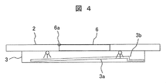
- the limiting portion 3b was set as an uphill slope, but in this embodiment, as shown in FIG. 4, the limiting portion 3b is set as a rising portion having a substantially right angle. However, since the height of the limiting portion 3b is not so large, it can be overcome relatively easily by the operation of the operator as in the first embodiment.
- the roller 4b (not shown) is temporarily restricted from moving in the same portion at the initial stage after the start of the opening operation, so that the same effect as that of the first embodiment can be obtained. Can be done.
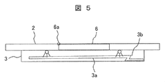
- the limiting portion 3b is an uphill slope or a rising portion having a substantially right angle, but in this embodiment, as shown in FIG. 5, the limiting portion 3b has a steeper substantially Z-shaped shape. And said. However, since the height of the limiting portion 3b is not so large, it can be overcome relatively easily by the operation of the operator as in the first and second embodiments.
- the roller 4b (not shown) is temporarily restricted from moving in the same portion at the initial stage after the start of the opening operation, so that the same effect as that of the first embodiment can be obtained. Can be done.
- a flat moving surface is formed in front of the uphill limiting portion 3b, and a gentle downhill moving surface is formed after the uphill limiting portion 3b.
- a downhill moving surface is formed in front of the uphill limiting portion 3b, and a flat moving surface is formed after the uphill limiting portion 3b.
- the guide 3a is formed with a downward slope portion 3d that descends immediately after the start of the opening operation, the opening operation of the ceiling shielding plates 4 and 5 can be started more smoothly. ..
- the ceiling shielding plates 4 and 5 are already somewhat folded, so that the ceiling shielding plate is relatively easy even if the guide 3a does not have a downward slope as in the first embodiment. 4 and 5 can be opened.
- the present invention is not limited to the above-mentioned examples, and includes various modifications.
- the above-described examples have been described in detail in order to explain the present invention in an easy-to-understand manner, and are not necessarily limited to those having all the described configurations. It is also possible to replace a part of the configuration of one embodiment with the configuration of another embodiment, and it is also possible to add the configuration of another embodiment to the configuration of one embodiment. In addition, it is possible to add, delete, or replace a part of the configuration of each embodiment with another configuration.
Abstract
The present invention provides an elevator device car ceiling structure in which, when shielding plates are opened, the shielding plates are prevented from falling down into the car at an accelerating speed because of the tare weights thereof, and thus safety is improved. Accordingly, this elevator device car is provided with a mounting frame fixed to a ceiling and openable/closable ceiling shielding plates that are mounted to the mounting frame, wherein: each of the ceiling shielding plates comprises two plates; center side end parts of both ceiling shielding plates are coupled to each other via a first coupling part; a roller or a slide body is mounted to an outer side end part of a first ceiling shielding plate; an outer side end part of a second ceiling shielding plate is rotatably coupled to an outer side end part of the mounting frame via a second coupling part; the mounting frame is provided with a guide for guiding movement of the slide body or the roller; and a restriction part for temporarily restricting movement of the slide body or the roller at an initial stage of opening operation of the ceiling shielding plates, is provided to the first ceiling shielding plate side of the guide.
Description
本発明は、開閉可能な遮蔽板を天井に備えた、エレベータ装置の乗りかごに関する。
The present invention relates to a car of an elevator device provided with a shield plate that can be opened and closed on the ceiling.
本技術分野の背景技術として、特許文献1がある。
Patent Document 1 is a background technology in this technical field.
この文献の請求項1には、「エレベータかご内の上方に設けられ、一面に複数の光源を配設された照明板と、この照明板の下方又は一体に設けられた照明ケースと、この照明ケースの端部が下方に回動可能に前記照明板に支持する取付ブラケットと、を有するエレベータかご内の天井照明装置」が記載されており、この構成により、天井照明装置のメインテナンスを容易にしている。
Claim 1 of this document states that "a lighting plate provided above the elevator car and having a plurality of light sources arranged on one surface, a lighting case provided below or integrally with the lighting plate, and the lighting thereof. A ceiling luminaire in an elevator car with a mounting bracket that rotates downwardly to support the luminaire at the end of the case "is described, which facilitates maintenance of the ceiling luminaire. There is.
しかしながら、特許文献1は、同文献の図1等に示されるように、一枚の照明ケース(本発明の天井遮蔽板に相当)の端部を可回転的に支持した構成であったため、メインテナンス時に照明ケースを開放する際には、照明ケースが自重により自由落下で加速度的に乗りかご内に大きく倒れこんでくることになり、乗りかご内の乗客や作業者に照明ケースが当たる恐れがあった。
However, as shown in FIG. 1 and the like of the same document, Patent Document 1 has a configuration in which the end portion of one lighting case (corresponding to the ceiling shielding plate of the present invention) is rotatably supported, and thus is maintained. Occasionally, when opening the lighting case, the lighting case will fall freely into the car due to its own weight, and the lighting case may fall into the car at an accelerated rate, causing the lighting case to hit passengers and workers in the car. It was.
そこで、本発明は、作業者等が天井遮蔽板を開放する際に、天井遮蔽板が自重により加速度的に乗りかご内に突出してくることを防止し、乗りかご内の乗客や作業者の安全性の向上を図った、エレベータ装置の乗りかごを提供することを目的とする。
Therefore, the present invention prevents the ceiling shield plate from acceleratingly protruding into the car due to its own weight when the worker or the like opens the ceiling shield plate, and is safe for passengers and workers in the car. The purpose is to provide a car for elevator equipment with improved performance.
上記課題を解決するために、本発明は、天井に固定した取付枠と、該取付枠に取り付けた開閉可能な天井遮蔽板と、を設けたエレベータ装置の乗りかごであって、前記天井遮蔽板は二枚で構成されており、両天井遮蔽板の中央側端部を第一連結部によって互いに回転可能に連結し、第一天井遮蔽板の外側端部にローラまたは摺動体を取り付けるとともに、第二天井遮蔽板の外側端部を第二連結部によって前記取付枠の外側端部に回転可能に連結し、前記取付枠には、前記ローラまたは前記摺動体の移動を案内するガイドを設け、該ガイドの前記第一天井遮蔽板側には、前記天井遮蔽板の開動作の初期において、前記ローラまたは前記摺動体の移動を一時的に制限する制限部を設けたエレベータ装置の乗りかごとした。
In order to solve the above problems, the present invention is a car of an elevator device provided with a mounting frame fixed to the ceiling and an openable / closable ceiling shielding plate attached to the mounting frame. Is composed of two sheets, and the central end portions of both ceiling shield plates are rotatably connected to each other by the first connecting portion, and a roller or a sliding body is attached to the outer end portion of the first ceiling shielding plate. (Ii) The outer end of the ceiling shield plate is rotatably connected to the outer end of the mounting frame by a second connecting portion, and the mounting frame is provided with a guide for guiding the movement of the roller or the sliding body. On the side of the first ceiling shield plate of the guide, an elevator device provided with a restriction portion that temporarily restricts the movement of the roller or the sliding body at the initial stage of the opening operation of the ceiling shield plate was used.
本発明の乗りかごによれば、作業者等が天井遮蔽板を開放する際に、天井遮蔽板が自重により加速度的に乗りかご内に突出してくることを防止し、乗りかご内の乗客や作業者の安全性の向上を図ることができる。なお、上述した以外の課題、構成および効果は、以下の実施例の説明により明らかにされる。
According to the car of the present invention, when a worker or the like opens the ceiling shield plate, the ceiling shield plate is prevented from acceleratingly protruding into the car due to its own weight, and passengers and work in the car It is possible to improve the safety of the person. Issues, configurations, and effects other than those described above will be clarified by the explanation of the following examples.
以下、本発明の実施例を図面に基づいて説明する。
Hereinafter, examples of the present invention will be described with reference to the drawings.
図1から図3を用いて、本発明の実施例1に係る、エレベータ装置の乗りかごを説明する。
The car of the elevator device according to the first embodiment of the present invention will be described with reference to FIGS. 1 to 3.
図1は、本実施例の乗りかご1の天丼側に設けた遮蔽板の閉状態を示す断面図である。ここに示すように、乗りかご1の天井2の下面には、複数の照明2aとそれらを囲む取付枠3が固定されており、この取付枠3の下部開口が二枚の透光性の天井遮蔽板4,5で覆われている。また、天井2の略中央部には、天井救出口を塞ぐ救出口遮蔽板6が、連結部6aによって開閉可能に連結されている。
FIG. 1 is a cross-sectional view showing a closed state of a shielding plate provided on the top bowl side of the car 1 of this embodiment. As shown here, a plurality of lights 2a and a mounting frame 3 surrounding them are fixed to the lower surface of the ceiling 2 of the car 1, and the lower opening of the mounting frame 3 is two translucent ceilings. It is covered with shielding plates 4 and 5. Further, a rescue outlet shielding plate 6 that closes the ceiling rescue outlet is connected to the substantially central portion of the ceiling 2 so as to be openable and closable by a connecting portion 6a.
このような構成の本実施例の乗りかご1では、エレベータ装置の運行時には閉状態の天井遮蔽板4,5を必要に応じて開状態にすることで、照明2aの交換や、天井救出口を利用した人の出入を可能にする。以下、天井遮蔽板4,5を開状態にするために用いる構造を中心に、乗りかご1の詳細を説明する。
In the car 1 of the present embodiment having such a configuration, the ceiling shield plates 4 and 5 in the closed state are opened as necessary when the elevator device is in operation, so that the lighting 2a can be replaced and the ceiling rescue outlet can be replaced. Allows users to enter and exit. Hereinafter, the details of the car 1 will be described with a focus on the structure used to open the ceiling shielding plates 4 and 5.
図1に示すように、天井遮蔽板4,5の中央側端部は、連結部4aによって互いに回転可能に連結されている。一方の天井遮蔽板4の外側端部には、取付枠3の一対の側面(図1の例では、紙面手前側と紙面奥側の二側面)に設けた一対のガイド3a内を、回転しながら移動する一対のローラ4bが設けられている。他方の天井遮蔽板5の外側端部には、天井遮蔽板5と取付枠3の外側端部を回転可能に連結する連結部5aが設けられている。なお、ここでは、天井遮蔽板4の外側端部にローラ4bを設けた構成を例示したが、ローラ4bに代え、ガイド3a内を滑りながら移動するピン等の摺動体を設けても良い。
As shown in FIG. 1, the central end portions of the ceiling shielding plates 4 and 5 are rotatably connected to each other by the connecting portion 4a. At the outer end of one ceiling shield plate 4, a pair of guides 3a provided on a pair of side surfaces of the mounting frame 3 (two side surfaces on the front side and the back side of the paper surface in the example of FIG. 1) are rotated. A pair of rollers 4b that move while being provided are provided. The outer end of the other ceiling shield 5 is provided with a connecting portion 5a that rotatably connects the ceiling shield 5 and the outer end of the mounting frame 3. Although the configuration in which the roller 4b is provided at the outer end of the ceiling shielding plate 4 is illustrated here, a sliding body such as a pin that moves while sliding in the guide 3a may be provided instead of the roller 4b.
また、天井遮蔽板5の上面の中央側端部には、可動式のロック体5bが取り付けられており、このロック体5bが取付枠3の側面から突出する固定部3cと係合している。このロック体5bが係合状態のときは、天井遮蔽板4,5が閉状態に保持されている。しかし、作業者がロック体5bを操作し係合を解くと、天井遮蔽板4,5の自重により、ローラ4bがガイド3aに案内されて図1の紙面左方向へ移動し、天井遮蔽板4,5の開動作が開始される。
A movable lock body 5b is attached to the central end of the upper surface of the ceiling shield plate 5, and the lock body 5b is engaged with a fixing portion 3c protruding from the side surface of the mounting frame 3. .. When the lock body 5b is in the engaged state, the ceiling shielding plates 4 and 5 are held in the closed state. However, when the operator operates the lock body 5b to disengage the engagement, the rollers 4b are guided by the guide 3a due to the weight of the ceiling shielding plates 4 and 5 and move to the left on the paper surface of FIG. 1, and the ceiling shielding plate 4 , 5 opening operation is started.
ここで、本実施例のガイド3aには、天井遮蔽板4,5の開動作の初期に、ローラ4bの移動を一時的に制限するための、上り坂の勾配とした制限部3bが形成されている。なお、制限部3bの前後には、制限部3bよりも穏やか移動面が設けられているので、制限部3bの前後では、ローラ4bの移動が制限されることがない。
Here, in the guide 3a of the present embodiment, a limiting portion 3b having an uphill slope is formed to temporarily limit the movement of the rollers 4b at the initial stage of the opening operation of the ceiling shielding plates 4 and 5. ing. Since a gentler moving surface than the limiting portion 3b is provided before and after the limiting portion 3b, the movement of the roller 4b is not restricted before and after the limiting portion 3b.
このような構成の乗りかご1によれば、作業者がロック体5bの係合を解くとローラ4bがガイド3aに沿って図示の右側から左側に移動するとともに、天井遮蔽板4,5を連結する連結部4aが下方に移動する。この結果、天井遮蔽板4,5は連結部4aを中心にして折り畳まれ、下方に凸となるV字状態となって開放される。
According to the car 1 having such a configuration, when the operator disengages the lock body 5b, the roller 4b moves from the right side to the left side in the figure along the guide 3a, and the ceiling shielding plates 4 and 5 are connected. The connecting portion 4a to be connected moves downward. As a result, the ceiling shielding plates 4 and 5 are folded around the connecting portion 4a and opened in a V-shaped state that is convex downward.
このため、特許文献1のように一枚構成の天井遮蔽板を使用した場合に比べ、開状態であっても天井遮蔽板が乗りかご1内に大きく突出することがなく、作業者や乗客が天井遮蔽板に衝突する可能性を抑制することができる。
Therefore, as compared with the case of using a single-sheet ceiling shielding plate as in Patent Document 1, the ceiling shielding plate does not protrude significantly into the car 1 even in the open state, and workers and passengers can use it. The possibility of collision with the ceiling shielding plate can be suppressed.
また、二枚の天井遮蔽板を使用する態様として、各天井遮蔽板の外側端部を可回転的に支持した観音開き方式とすることで、開状態時の各天井遮蔽板の突出寸法を小さくすることもできるが、この方式では、開放した二枚の天井遮蔽板が自重により自由落下で加速度的に乗りかご1内に倒れこんでくるため、乗りかご1内の乗客や作業者が天井遮蔽板を避けることができず、天井遮蔽板に当たる恐れもあった。
In addition, as a mode in which two ceiling shield plates are used, the protruding dimension of each ceiling shield plate in the open state is reduced by adopting a Kannon opening method in which the outer end of each ceiling shield plate is rotatably supported. However, in this method, the two open ceiling shields fall freely into the car 1 due to their own weight, so that passengers and workers in the car 1 can fall into the ceiling shields. Was unavoidable, and there was a risk of hitting the ceiling shield.
これに対し、図1に示した本実施例の構成では、ガイド3aの制限部3bと天井遮蔽板4のローラ4bの相互作用により、開動作初期の天井遮蔽板の落下速度が抑制されるだけでなく、開動作初期の天井遮蔽板の落下量も制限されるため、観音開き方式のように二枚の天井遮蔽板が加速度的に乗りかご1内に突出してくることもなくなり、乗客や作業者が開動作中の天井遮蔽板に当たる可能性も極めて低くなる。この点については、図2、図3を用いて、さらに詳細に説明する。
<天丼遮蔽板の開動作初期状態>
図2は、乗りかご1の天丼遮蔽板の開動作初期状態を示す断面図である。 On the other hand, in the configuration of the present embodiment shown in FIG. 1, the falling speed of the ceiling shielding plate at the initial stage of opening operation is only suppressed by the interaction between thelimiting portion 3b of the guide 3a and the roller 4b of the ceiling shielding plate 4. In addition, since the amount of fall of the ceiling shield plate at the initial stage of opening operation is also limited, the two ceiling shield plates do not accelerately protrude into the car 1 as in the double door method, and passengers and workers do not. Is extremely unlikely to hit the ceiling shield during open operation. This point will be described in more detail with reference to FIGS. 2 and 3.
<Initial state of opening operation of the bowl shield plate>
FIG. 2 is a cross-sectional view showing an initial state of the opening operation of the bowl shield plate of the car 1.
<天丼遮蔽板の開動作初期状態>
図2は、乗りかご1の天丼遮蔽板の開動作初期状態を示す断面図である。 On the other hand, in the configuration of the present embodiment shown in FIG. 1, the falling speed of the ceiling shielding plate at the initial stage of opening operation is only suppressed by the interaction between the
<Initial state of opening operation of the bowl shield plate>
FIG. 2 is a cross-sectional view showing an initial state of the opening operation of the bowl shield plate of the car 1.
本実施例のガイド3aには、天井遮蔽板4側の端部に平坦な移動面が設けられている。このため、作業者がロック体5bの係合を解いた直後は、天井遮蔽板4、5の自重により、ローラ4bはガイド3aの端部の平坦な移動面を、滑らかに移動開始する。しかし、ガイド3aの途中には上り坂の勾配とした制限部3bが形成されているため、開動作開始直後で速度の比較的遅いローラ4bは、制限部3bを乗り越えることができず、制限部3bの手前で一旦停止する。
The guide 3a of this embodiment is provided with a flat moving surface at the end on the ceiling shielding plate 4 side. Therefore, immediately after the operator disengages the lock body 5b, the roller 4b smoothly starts moving on the flat moving surface at the end of the guide 3a due to the weight of the ceiling shielding plates 4 and 5. However, since the limiting portion 3b having an uphill slope is formed in the middle of the guide 3a, the roller 4b having a relatively slow speed immediately after the start of the opening operation cannot get over the limiting portion 3b, and the limiting portion 3b cannot be overcome. It stops just before 3b.
この一旦停止状態となったとき、ロック体5bの係合を解いた作業者は、天井遮蔽板4,5を更に開く必要があるかや、天井遮蔽板4,5の可動範囲に乗客や他の作業者がいないかを判断する。例えば、天井遮蔽板4側の照明2aだけを交換するのであれば、天井遮蔽板を半開き状態とすれば十分であるので、それ以上の開動作は不要と判断することもできるし、乗りかご1内に他の作業者や乗客がいる場合は、更なる開動作を行う前に、天井遮蔽板の突出を注意喚起することもできる。
When the lock body 5b is temporarily stopped, the worker who disengages the lock body 5b needs to open the ceiling shield plates 4 and 5 further, or passengers and others within the movable range of the ceiling shield plates 4 and 5. Determine if there are any workers. For example, if only the lighting 2a on the ceiling shielding plate 4 side is to be replaced, it is sufficient to open the ceiling shielding plate in a half-open state, so that it can be determined that further opening operation is unnecessary, and the car 1 If there are other workers or passengers inside, it is possible to call attention to the protrusion of the ceiling shield before performing further opening operations.
そして、天井遮蔽板4,5をさらに開く必要があると判断した場合は、作業者は、天井遮蔽板4をさらに左方向にスライドさせるか、連結部4aをさらに下方に下げる。すると、ローラ4bが上り勾配の制限部3bを比較的簡単に乗り越え、開動作を継続することできる。
<天丼遮蔽板の開動作終期状態>
図3は、乗りかご1の天丼遮蔽の開動作終期状態を示す断面図である。 Then, when it is determined that the ceiling shield plates 4 and 5 need to be opened further, the operator slides the ceiling shield plate 4 further to the left or lowers the connecting portion 4a further downward. Then, the roller 4b can overcome the uphill limiting portion 3b relatively easily and continue the opening operation.
<End of open operation of Tendon shield plate>
FIG. 3 is a cross-sectional view showing the final state of the opening operation of the bowl shield of the car 1.
<天丼遮蔽板の開動作終期状態>
図3は、乗りかご1の天丼遮蔽の開動作終期状態を示す断面図である。 Then, when it is determined that the
<End of open operation of Tendon shield plate>
FIG. 3 is a cross-sectional view showing the final state of the opening operation of the bowl shield of the car 1.
作業者が天井遮蔽板4等を操作して、ローラ4bが上り勾配の制限部3bを乗り越えると、ローラ4bはガイド3aの穏やかな下り勾配部分を左方向に移動することとなる。この結果、図3に示すように、天井遮蔽板5の連結部5aにローラ4bが接近し、天井遮蔽板4,5が連結部4aを中心にしてほぼ二つ折りにされたV字状態となる。このため、取付枠3の下部開口は、天井遮蔽板4,5によって覆われた図1の閉状態から、大きく開かれた図3の開状態になる。図3の開状態となれば、作業者は、天井遮蔽板4側の照明2aだけでなく、天井遮蔽板5側の照明2aも容易に交換することができる。
When the operator operates the ceiling shield plate 4 or the like and the roller 4b gets over the limiting portion 3b of the uphill slope, the roller 4b moves to the left on the gentle downhill slope portion of the guide 3a. As a result, as shown in FIG. 3, the roller 4b approaches the connecting portion 5a of the ceiling shielding plate 5, and the ceiling shielding plates 4 and 5 are substantially folded in half around the connecting portion 4a in a V-shape. .. Therefore, the lower opening of the mounting frame 3 changes from the closed state of FIG. 1 covered by the ceiling shielding plates 4 and 5 to the wide open state of FIG. When the state of FIG. 3 is opened, the operator can easily replace not only the lighting 2a on the ceiling shielding plate 4 side but also the lighting 2a on the ceiling shielding plate 5 side.
図3に示す開状態は、乗りかご1内の乗客をかご上から救出する救出経路を確保するときに特に効果的である。図3を兼用して説明すると、かご上の作業者が救出口遮蔽板6を図3に示すように開いた後、かご上からロック体5bの係合を手動で解く。このとき、かご上の作業者からは、乗りかご1内の状況や乗客を確認できないが、ローラ4bの移動がガイド3aの制限部3bで一時的に制限されるため、天井遮蔽板4,5は、乗りかご1内にわずかに突出した図2に示す状態で一旦停止する。そこで、かご上の作業者はまず、乗りかご1内の乗客に声がけ等して、乗客を安全な位置(図1から図3の例では、天井遮蔽板4,5の可動範囲外となる、乗りかご1の右側等)に誘導する。
The open state shown in FIG. 3 is particularly effective when securing a rescue route for rescuing passengers in the car 1 from above the car. Explaining with reference to FIG. 3, after the operator on the car opens the rescue exit shielding plate 6 as shown in FIG. 3, the lock body 5b is manually disengaged from above the car. At this time, the operator on the car cannot confirm the situation in the car 1 and the passengers, but since the movement of the roller 4b is temporarily restricted by the limiting portion 3b of the guide 3a, the ceiling shielding plates 4 and 5 Temporarily stops in the state shown in FIG. 2 slightly protruding into the car 1. Therefore, the worker on the car first calls out to the passengers in the car 1 and puts the passengers in a safe position (in the examples of FIGS. 1 to 3, the ceiling shielding plates 4 and 5 are out of the movable range). , Right side of car 1 etc.).
乗客の安全な位置への移動を確認すると、かご上の作業者は、天井遮蔽板4や連結部4aを押し下げ、ローラ4bに上り勾配の制限部3bを乗り越えさせる。ローラ4bが上り勾配の制限部3bを乗り越えると、ローラ4bは穏やかな下り勾配のガイド3aを進み、最終的に、図3に示すように天井遮蔽板5の連結部5aにローラ4bが接近し、天井遮蔽板4,5が連結部4aを中心にしてほぼ二つ折りにされたV字状態となる。この一連の開動作時に、乗りかご1内の乗客等は、天井遮蔽板4,5の可動範囲を避けた安全な位置にいるので、天井遮蔽板4,5が乗客等に当たることがない。
After confirming that the passengers have moved to a safe position, the worker on the car pushes down the ceiling shield plate 4 and the connecting portion 4a, and causes the roller 4b to overcome the uphill limiting portion 3b. When the roller 4b gets over the limiting portion 3b of the uphill slope, the roller 4b advances on the guide 3a of the gentle downhill slope, and finally the roller 4b approaches the connecting portion 5a of the ceiling shielding plate 5 as shown in FIG. , The ceiling shielding plates 4 and 5 are folded in half around the connecting portion 4a to form a V-shape. During this series of opening operations, the passengers and the like in the car 1 are in a safe position avoiding the movable range of the ceiling shield plates 4 and 5, so that the ceiling shield plates 4 and 5 do not hit the passengers and the like.
以上で説明したように、本実施例の乗りかごによれば、天井遮蔽板を開放する際に、天井遮蔽板が自重により加速度的に乗りかご内に大きく倒れ込んでくることを防止して、乗りかご内の乗客や作業者の安全性の向上を図ることができる。
As described above, according to the car of the present embodiment, when the ceiling shield plate is opened, it is prevented that the ceiling shield plate is acceleratedly collapsed into the car due to its own weight, and the passenger rides. It is possible to improve the safety of passengers and workers in the car.
次に、図4を用いて、本発明の実施例2の乗りかごを説明する。なお、実施例1との共通点は重複説明を省略する。
Next, the car of the second embodiment of the present invention will be described with reference to FIG. It should be noted that the common points with the first embodiment will be omitted.
実施例1では、制限部3bを上り坂の勾配としたが、本実施例では、図4に示すように、制限部3bをほぼ直角な立ち上げ部とした。しかし、制限部3bの高さは差ほど大きくないため、実施例1と同様に、作業者の操作により比較的に容易に乗り越えることができる。
In the first embodiment, the limiting portion 3b was set as an uphill slope, but in this embodiment, as shown in FIG. 4, the limiting portion 3b is set as a rising portion having a substantially right angle. However, since the height of the limiting portion 3b is not so large, it can be overcome relatively easily by the operation of the operator as in the first embodiment.
このような形状の制限部3bを設けた場合においても、図示しないローラ4bは開動作開始後の初期において同部で一時的に移動が制限されるため、実施例1と同等の効果を得ることができる。
Even when the limiting portion 3b having such a shape is provided, the roller 4b (not shown) is temporarily restricted from moving in the same portion at the initial stage after the start of the opening operation, so that the same effect as that of the first embodiment can be obtained. Can be done.
次に、図5を用いて、本発明の実施例3の乗りかごを説明する示す断面図である。なお、上記した実施例との共通点は重複説明を省略する。
Next, it is sectional drawing which shows explaining the car of Example 3 of this invention using FIG. It should be noted that the common points with the above-described embodiment will be omitted.
先の実施例では、制限部3bを上り坂の勾配またはほぼ直角な立ち上げ部としたが、本実施例では、図5に示すように、制限部3bをより急峻な略Z字状の形状とした。しかし、制限部3bの高さは差ほど大きくないため、実施例1、2と同様に、作業者の操作により比較的に容易に乗り越えることができる。
In the previous embodiment, the limiting portion 3b is an uphill slope or a rising portion having a substantially right angle, but in this embodiment, as shown in FIG. 5, the limiting portion 3b has a steeper substantially Z-shaped shape. And said. However, since the height of the limiting portion 3b is not so large, it can be overcome relatively easily by the operation of the operator as in the first and second embodiments.
このような形状の制限部3bを設けた場合においても、図示しないローラ4bは開動作開始後の初期において同部で一時的に移動が制限されるため、実施例1と同等の効果を得ることができる。
Even when the limiting portion 3b having such a shape is provided, the roller 4b (not shown) is temporarily restricted from moving in the same portion at the initial stage after the start of the opening operation, so that the same effect as that of the first embodiment can be obtained. Can be done.
次に、図6を用いて、本発明の実施例4の乗りかごを説明する。なお、上記した実施例との共通点は重複説明を省略する。
Next, the car of the fourth embodiment of the present invention will be described with reference to FIG. It should be noted that the common points with the above-described embodiment will be omitted.
実施例1のガイド3aでは、上り勾配の制限部3bの前に平坦な移動面が形成されており、上り勾配の制限部3bの後に穏やかな下り勾配の移動面が形成されていたが、本実施例では、上り勾配の制限部3bの前に下り勾配の移動面が形成されており、上り勾配の制限部3bの後に平坦な移動面が形成されている。
In the guide 3a of the first embodiment, a flat moving surface is formed in front of the uphill limiting portion 3b, and a gentle downhill moving surface is formed after the uphill limiting portion 3b. In the embodiment, a downhill moving surface is formed in front of the uphill limiting portion 3b, and a flat moving surface is formed after the uphill limiting portion 3b.
このような構成によれば、ガイド3aには開動作開始後すぐに下りとなる下り勾配部3dが形成されているため天井遮蔽板4,5の開動作開始をより円滑に開始させることができる。
According to such a configuration, since the guide 3a is formed with a downward slope portion 3d that descends immediately after the start of the opening operation, the opening operation of the ceiling shielding plates 4 and 5 can be started more smoothly. ..
また、ローラ4bが制限部3bを通過すると、天井遮蔽板4,5は既に幾分折り畳まれているため、実施例1のようにガイド3aに下り勾配がなくても比較的容易に天井遮蔽板4,5を開操作することができる。
Further, when the roller 4b passes through the limiting portion 3b, the ceiling shielding plates 4 and 5 are already somewhat folded, so that the ceiling shielding plate is relatively easy even if the guide 3a does not have a downward slope as in the first embodiment. 4 and 5 can be opened.
尚、本発明は、上述した実施例に限定するものではなく、様々な変形例が含まれる。例えば、上述した実施例は本発明を分かり易く説明するために詳細に説明したものであり、必ずしも説明した全ての構成を備えるものに限定するものではない。またある実施例の構成の一部を他の実施例の構成に置き換えることが可能であり、また、ある実施例の構成に他の実施例の構成を加えることも可能である。また、各実施例の構成の一部について、他の構成の追加、削除、置換をすることが可能である。
The present invention is not limited to the above-mentioned examples, and includes various modifications. For example, the above-described examples have been described in detail in order to explain the present invention in an easy-to-understand manner, and are not necessarily limited to those having all the described configurations. It is also possible to replace a part of the configuration of one embodiment with the configuration of another embodiment, and it is also possible to add the configuration of another embodiment to the configuration of one embodiment. In addition, it is possible to add, delete, or replace a part of the configuration of each embodiment with another configuration.
1 乗りかご
2 天井
2a 照明
3 取付枠
3a ガイド
3b 制限部
3c 固定部
3d 下り勾配部
4,5 天井遮蔽板
4a、5a 連結部
4b ローラ
5b ロック体
6 救出口遮蔽板
6a 連結部 1Car 2 Ceiling 2a Lighting 3 Mounting frame 3a Guide 3b Restriction part 3c Fixing part 3d Downward slope part 4, 5 Ceiling shield plate 4a, 5a Connection part 4b Roller 5b Lock body 6 Rescue shield plate 6a Connection part
2 天井
2a 照明
3 取付枠
3a ガイド
3b 制限部
3c 固定部
3d 下り勾配部
4,5 天井遮蔽板
4a、5a 連結部
4b ローラ
5b ロック体
6 救出口遮蔽板
6a 連結部 1
Claims (7)
- 天井に固定した取付枠と、
該取付枠に取り付けた開閉可能な天井遮蔽板と、
を設けたエレベータ装置の乗りかごであって、
前記天井遮蔽板は二枚で構成されており、両天井遮蔽板の中央側端部を第一連結部によって互いに回転可能に連結し、第一天井遮蔽板の外側端部にローラまたは摺動体を取り付けるとともに、第二天井遮蔽板の外側端部を第二連結部によって前記取付枠の外側端部に回転可能に連結し、
前記取付枠には、前記ローラまたは前記摺動体の移動を案内するガイドを設け、該ガイドの前記第一天井遮蔽板側には、前記天井遮蔽板の開動作の初期において、前記ローラまたは前記摺動体の移動を一時的に制限する制限部を設けたことを特徴とするエレベータ装置の乗りかご。 With a mounting frame fixed to the ceiling
An openable and closable ceiling shield attached to the mounting frame,
It is a car of an elevator device equipped with
The ceiling shield plate is composed of two sheets, and the central end portions of both ceiling shield plates are rotatably connected to each other by a first connecting portion, and a roller or a sliding body is attached to the outer end portion of the first ceiling shield plate. At the same time as mounting, the outer end of the second ceiling shield plate is rotatably connected to the outer end of the mounting frame by the second connecting portion.
The mounting frame is provided with a guide for guiding the movement of the roller or the sliding body, and the roller or the sliding member is provided on the first ceiling shielding plate side of the guide at the initial stage of opening of the ceiling shielding plate. Elevator car that features a restriction section that temporarily restricts the movement of moving objects. - 前記天井遮蔽板の開動作時には、前記ローラまたは前記摺動体が前記ガイドに沿って移動し、前記第一天井遮蔽板と前記第二天井遮蔽板が前記第一連結部を中心にして折り畳まれ、下方に凸となるV字状態となることを特徴とする請求項1に記載のエレベータ装置の乗りかご。 When the ceiling shield plate is opened, the roller or the sliding body moves along the guide, and the first ceiling shield plate and the second ceiling shield plate are folded around the first connecting portion. The car of the elevator device according to claim 1, wherein the elevator device is in a V-shaped state that is convex downward.
- 前記制限部は、上り坂の勾配であることを特徴とする請求項1または請求項2に記載のエレベータ装置の乗りかご。 The elevator device car according to claim 1 or 2, wherein the restriction portion has an uphill slope.
- 前記制限部は、ほぼ直角な立ち上げ部であることを特徴とする請求項1または請求項2に記載のエレベータ装置の乗りかご。 The elevator device car according to claim 1 or 2, wherein the limiting portion is a rising portion having a substantially right angle.
- 前記制限部は、急峻な略Z字状の形状であることを特徴とする請求項1または請求項2に記載のエレベータ装置の乗りかご。 The car of the elevator device according to claim 1 or 2, wherein the restriction portion has a steep, substantially Z-shaped shape.
- 前記制限部の前側には平坦な移動面が形成されており、前記制限部の後側には下り勾配の移動面が形成されていることを特徴とする請求項1または請求項2に記載のエレベータ装置の乗りかご。 The first or second aspect of the present invention, wherein a flat moving surface is formed on the front side of the limiting portion, and a downward slope moving surface is formed on the rear side of the limiting portion. Elevator car.
- 前記制限部の前側には下り勾配の移動面が形成されており、前記制限部の後側には平坦な移動面が形成されていることを特徴とする請求項1または請求項2に記載のエレベータ装置の乗りかご。 The first or second aspect of the present invention, wherein a downward slope moving surface is formed on the front side of the limiting portion, and a flat moving surface is formed on the rear side of the limiting portion. Elevator car.
Priority Applications (3)
| Application Number | Priority Date | Filing Date | Title |
|---|---|---|---|
| CN201980099852.1A CN114364628B (en) | 2019-08-30 | 2019-08-30 | Elevator car of elevator device |
| JP2021541921A JP7273164B2 (en) | 2019-08-30 | 2019-08-30 | elevator car |
| PCT/JP2019/034109 WO2021038828A1 (en) | 2019-08-30 | 2019-08-30 | Elevator device car |
Applications Claiming Priority (1)
| Application Number | Priority Date | Filing Date | Title |
|---|---|---|---|
| PCT/JP2019/034109 WO2021038828A1 (en) | 2019-08-30 | 2019-08-30 | Elevator device car |
Publications (1)
| Publication Number | Publication Date |
|---|---|
| WO2021038828A1 true WO2021038828A1 (en) | 2021-03-04 |
Family
ID=74685013
Family Applications (1)
| Application Number | Title | Priority Date | Filing Date |
|---|---|---|---|
| PCT/JP2019/034109 WO2021038828A1 (en) | 2019-08-30 | 2019-08-30 | Elevator device car |
Country Status (3)
| Country | Link |
|---|---|
| JP (1) | JP7273164B2 (en) |
| CN (1) | CN114364628B (en) |
| WO (1) | WO2021038828A1 (en) |
Citations (7)
| Publication number | Priority date | Publication date | Assignee | Title |
|---|---|---|---|---|
| JPS60170374U (en) * | 1984-04-18 | 1985-11-12 | 三菱電機株式会社 | Elevator cab lighting system |
| JPH02175577A (en) * | 1988-12-26 | 1990-07-06 | Hitachi Ltd | Guide device for lighting plate of elevator cage |
| JPH0511271Y2 (en) * | 1987-05-22 | 1993-03-19 | ||
| JPH0647273U (en) * | 1992-12-04 | 1994-06-28 | オーチス エレベータ カンパニー | Elevator basket ceiling structure |
| JP2005022768A (en) * | 2003-06-30 | 2005-01-27 | Mitsubishi Electric Corp | Door device of elevator |
| JP2009155033A (en) * | 2007-12-26 | 2009-07-16 | Toshiba Elevator Co Ltd | Elevator door device |
| JP2019182572A (en) * | 2018-04-05 | 2019-10-24 | 株式会社日立ビルシステム | Car and elevator |
Family Cites Families (4)
| Publication number | Priority date | Publication date | Assignee | Title |
|---|---|---|---|---|
| CN2407305Y (en) * | 2000-02-01 | 2000-11-22 | 合肥美菱股份有限公司 | Steadily moving refrigerator drawer supported by rollers |
| CN203451003U (en) * | 2013-09-18 | 2014-02-26 | 重庆富士电梯有限责任公司 | Machine roomless elevator carriage |
| CN204251120U (en) * | 2014-11-17 | 2015-04-08 | 广东富本电梯有限公司 | A kind of lift safety window device |
| JP2016166076A (en) * | 2015-03-10 | 2016-09-15 | 東芝エレベータ株式会社 | Ceiling luminaire in elevator car |
-
2019
- 2019-08-30 WO PCT/JP2019/034109 patent/WO2021038828A1/en active Application Filing
- 2019-08-30 JP JP2021541921A patent/JP7273164B2/en active Active
- 2019-08-30 CN CN201980099852.1A patent/CN114364628B/en active Active
Patent Citations (7)
| Publication number | Priority date | Publication date | Assignee | Title |
|---|---|---|---|---|
| JPS60170374U (en) * | 1984-04-18 | 1985-11-12 | 三菱電機株式会社 | Elevator cab lighting system |
| JPH0511271Y2 (en) * | 1987-05-22 | 1993-03-19 | ||
| JPH02175577A (en) * | 1988-12-26 | 1990-07-06 | Hitachi Ltd | Guide device for lighting plate of elevator cage |
| JPH0647273U (en) * | 1992-12-04 | 1994-06-28 | オーチス エレベータ カンパニー | Elevator basket ceiling structure |
| JP2005022768A (en) * | 2003-06-30 | 2005-01-27 | Mitsubishi Electric Corp | Door device of elevator |
| JP2009155033A (en) * | 2007-12-26 | 2009-07-16 | Toshiba Elevator Co Ltd | Elevator door device |
| JP2019182572A (en) * | 2018-04-05 | 2019-10-24 | 株式会社日立ビルシステム | Car and elevator |
Also Published As
| Publication number | Publication date |
|---|---|
| JPWO2021038828A1 (en) | 2021-03-04 |
| JP7273164B2 (en) | 2023-05-12 |
| CN114364628A (en) | 2022-04-15 |
| CN114364628B (en) | 2023-11-14 |
Similar Documents
| Publication | Publication Date | Title |
|---|---|---|
| TWI531521B (en) | Vibration suppressing device for elevator hoist | |
| EP0985626B1 (en) | Elevator control panel opening/closing device | |
| JP2008044734A (en) | Elevator car device | |
| EP0850188B1 (en) | Arrangement in the opening and closing of automatic elevator doors, and a door coupler | |
| EP3429953A1 (en) | Elevator car, elevator system and method of maintaining an elevator system | |
| WO2021038828A1 (en) | Elevator device car | |
| JP5294481B2 (en) | Evacuation door for tunnel | |
| JP2016150835A (en) | Elevator device | |
| EP1627842B1 (en) | Door device of elevator | |
| JP2019182572A (en) | Car and elevator | |
| JP2012082061A (en) | Rescue device and elevator | |
| US20200406068A1 (en) | Landar emergency evacuation system for high-rise abodes | |
| JP2525343B2 (en) | Elevator door device | |
| JP2016145092A (en) | Elevator device | |
| JPH05246663A (en) | Wind rectifying device for elevator cage | |
| JPH04298485A (en) | Elevator boarding place door | |
| JP7097532B2 (en) | Elevator three-sided frame | |
| JP2007521205A (en) | Elevator door operator and interlock arrangement | |
| JP2011037617A (en) | Cage of elevator | |
| JP6321225B1 (en) | Elevator equipment | |
| JPH08127484A (en) | Door structure of elevator | |
| JP2002371766A (en) | Self-closing sliding fire door device with smoke-blocking function | |
| JP2017197368A (en) | Door device of elevator and elevator system | |
| JP6229945B2 (en) | Elevator door opening and closing device | |
| JP2001253659A (en) | Machine room of elevator for station |
Legal Events
| Date | Code | Title | Description |
|---|---|---|---|
| 121 | Ep: the epo has been informed by wipo that ep was designated in this application |
Ref document number: 19943427 Country of ref document: EP Kind code of ref document: A1 |
|
| ENP | Entry into the national phase |
Ref document number: 2021541921 Country of ref document: JP Kind code of ref document: A |
|
| NENP | Non-entry into the national phase |
Ref country code: DE |
|
| 122 | Ep: pct application non-entry in european phase |
Ref document number: 19943427 Country of ref document: EP Kind code of ref document: A1 |