WO2021033216A1 - Processor for endoscope, endoscope system, information processing device, program, and information processing method - Google Patents
Processor for endoscope, endoscope system, information processing device, program, and information processing method Download PDFInfo
- Publication number
- WO2021033216A1 WO2021033216A1 PCT/JP2019/032134 JP2019032134W WO2021033216A1 WO 2021033216 A1 WO2021033216 A1 WO 2021033216A1 JP 2019032134 W JP2019032134 W JP 2019032134W WO 2021033216 A1 WO2021033216 A1 WO 2021033216A1
- Authority
- WO
- WIPO (PCT)
- Prior art keywords
- system information
- information
- learning model
- output
- model
- Prior art date
Links
Images


Classifications
-
- A—HUMAN NECESSITIES
- A61—MEDICAL OR VETERINARY SCIENCE; HYGIENE
- A61B—DIAGNOSIS; SURGERY; IDENTIFICATION
- A61B1/00—Instruments for performing medical examinations of the interior of cavities or tubes of the body by visual or photographical inspection, e.g. endoscopes; Illuminating arrangements therefor
- A61B1/00002—Operational features of endoscopes
- A61B1/00004—Operational features of endoscopes characterised by electronic signal processing
- A61B1/00009—Operational features of endoscopes characterised by electronic signal processing of image signals during a use of endoscope
- A61B1/000094—Operational features of endoscopes characterised by electronic signal processing of image signals during a use of endoscope extracting biological structures
-
- A—HUMAN NECESSITIES
- A61—MEDICAL OR VETERINARY SCIENCE; HYGIENE
- A61B—DIAGNOSIS; SURGERY; IDENTIFICATION
- A61B1/00—Instruments for performing medical examinations of the interior of cavities or tubes of the body by visual or photographical inspection, e.g. endoscopes; Illuminating arrangements therefor
- A61B1/00002—Operational features of endoscopes
- A61B1/00057—Operational features of endoscopes provided with means for testing or calibration
-
- A—HUMAN NECESSITIES
- A61—MEDICAL OR VETERINARY SCIENCE; HYGIENE
- A61B—DIAGNOSIS; SURGERY; IDENTIFICATION
- A61B1/00—Instruments for performing medical examinations of the interior of cavities or tubes of the body by visual or photographical inspection, e.g. endoscopes; Illuminating arrangements therefor
- A61B1/00002—Operational features of endoscopes
- A61B1/00004—Operational features of endoscopes characterised by electronic signal processing
- A61B1/00006—Operational features of endoscopes characterised by electronic signal processing of control signals
-
- A—HUMAN NECESSITIES
- A61—MEDICAL OR VETERINARY SCIENCE; HYGIENE
- A61B—DIAGNOSIS; SURGERY; IDENTIFICATION
- A61B1/00—Instruments for performing medical examinations of the interior of cavities or tubes of the body by visual or photographical inspection, e.g. endoscopes; Illuminating arrangements therefor
- A61B1/00002—Operational features of endoscopes
- A61B1/00004—Operational features of endoscopes characterised by electronic signal processing
- A61B1/00009—Operational features of endoscopes characterised by electronic signal processing of image signals during a use of endoscope
- A61B1/000096—Operational features of endoscopes characterised by electronic signal processing of image signals during a use of endoscope using artificial intelligence
-
- A—HUMAN NECESSITIES
- A61—MEDICAL OR VETERINARY SCIENCE; HYGIENE
- A61B—DIAGNOSIS; SURGERY; IDENTIFICATION
- A61B1/00—Instruments for performing medical examinations of the interior of cavities or tubes of the body by visual or photographical inspection, e.g. endoscopes; Illuminating arrangements therefor
- A61B1/00002—Operational features of endoscopes
- A61B1/00043—Operational features of endoscopes provided with output arrangements
- A61B1/00055—Operational features of endoscopes provided with output arrangements for alerting the user
-
- G—PHYSICS
- G06—COMPUTING; CALCULATING OR COUNTING
- G06T—IMAGE DATA PROCESSING OR GENERATION, IN GENERAL
- G06T7/00—Image analysis
- G06T7/0002—Inspection of images, e.g. flaw detection
- G06T7/0012—Biomedical image inspection
-
- G—PHYSICS
- G16—INFORMATION AND COMMUNICATION TECHNOLOGY [ICT] SPECIALLY ADAPTED FOR SPECIFIC APPLICATION FIELDS
- G16H—HEALTHCARE INFORMATICS, i.e. INFORMATION AND COMMUNICATION TECHNOLOGY [ICT] SPECIALLY ADAPTED FOR THE HANDLING OR PROCESSING OF MEDICAL OR HEALTHCARE DATA
- G16H30/00—ICT specially adapted for the handling or processing of medical images
- G16H30/40—ICT specially adapted for the handling or processing of medical images for processing medical images, e.g. editing
-
- G—PHYSICS
- G16—INFORMATION AND COMMUNICATION TECHNOLOGY [ICT] SPECIALLY ADAPTED FOR SPECIFIC APPLICATION FIELDS
- G16H—HEALTHCARE INFORMATICS, i.e. INFORMATION AND COMMUNICATION TECHNOLOGY [ICT] SPECIALLY ADAPTED FOR THE HANDLING OR PROCESSING OF MEDICAL OR HEALTHCARE DATA
- G16H40/00—ICT specially adapted for the management or administration of healthcare resources or facilities; ICT specially adapted for the management or operation of medical equipment or devices
- G16H40/40—ICT specially adapted for the management or administration of healthcare resources or facilities; ICT specially adapted for the management or operation of medical equipment or devices for the management of medical equipment or devices, e.g. scheduling maintenance or upgrades
-
- G—PHYSICS
- G06—COMPUTING; CALCULATING OR COUNTING
- G06T—IMAGE DATA PROCESSING OR GENERATION, IN GENERAL
- G06T2207/00—Indexing scheme for image analysis or image enhancement
- G06T2207/10—Image acquisition modality
- G06T2207/10024—Color image
-
- G—PHYSICS
- G06—COMPUTING; CALCULATING OR COUNTING
- G06T—IMAGE DATA PROCESSING OR GENERATION, IN GENERAL
- G06T2207/00—Indexing scheme for image analysis or image enhancement
- G06T2207/10—Image acquisition modality
- G06T2207/10068—Endoscopic image
-
- G—PHYSICS
- G06—COMPUTING; CALCULATING OR COUNTING
- G06T—IMAGE DATA PROCESSING OR GENERATION, IN GENERAL
- G06T2207/00—Indexing scheme for image analysis or image enhancement
- G06T2207/20—Special algorithmic details
- G06T2207/20081—Training; Learning
-
- G—PHYSICS
- G06—COMPUTING; CALCULATING OR COUNTING
- G06T—IMAGE DATA PROCESSING OR GENERATION, IN GENERAL
- G06T2207/00—Indexing scheme for image analysis or image enhancement
- G06T2207/20—Special algorithmic details
- G06T2207/20084—Artificial neural networks [ANN]
-
- G—PHYSICS
- G06—COMPUTING; CALCULATING OR COUNTING
- G06T—IMAGE DATA PROCESSING OR GENERATION, IN GENERAL
- G06T2207/00—Indexing scheme for image analysis or image enhancement
- G06T2207/30—Subject of image; Context of image processing
- G06T2207/30004—Biomedical image processing
- G06T2207/30028—Colon; Small intestine
-
- G—PHYSICS
- G06—COMPUTING; CALCULATING OR COUNTING
- G06T—IMAGE DATA PROCESSING OR GENERATION, IN GENERAL
- G06T2207/00—Indexing scheme for image analysis or image enhancement
- G06T2207/30—Subject of image; Context of image processing
- G06T2207/30004—Biomedical image processing
- G06T2207/30092—Stomach; Gastric
Definitions
- the present invention relates to an endoscope processor, an endoscope system, an information processing device, a program, and an information processing method.
- Patent Document 1 discloses an image processing device that prevents misalignment between a mark indicating a lesion portion attached to an endoscopic image and an endoscopic image.
- Patent Document 1 when a system abnormality that affects the image quality occurs, the cause of the abnormality (for example, image setting, optical system, light source, electric circuit, etc.) may not be correctly identified. There is.
- One aspect is to provide an endoscope processor or the like that can identify the cause of a system abnormality using a learned learning model.
- the endoscope processor has an image acquisition unit that acquires an endoscopic image taken by using the first system information and parameters based on the endoscopic image acquired by the image acquisition unit.
- a calculation unit that calculates, a first learning model that outputs an identification result that identifies a part of a subject when a parameter calculated by the calculation unit is input, a parameter calculated by the calculation unit, and the first learning. Determine the difference between the second learning model that outputs the second system information when the identification result output by the model is input, the second system information output by the second learning model, and the first system information. It is characterized by including a determination unit.
- FIG. 1 is a schematic view showing a configuration example of an endoscope system.
- the system shown in FIG. 1 is inserted into the body of a subject to take an image, and the endoscope 1 outputs an image signal to be observed, and the image signal output by the endoscope 1 is converted into an endoscope image.
- It includes a processor 2 for an endoscope and a display device 3 for displaying an endoscopic image or the like. Each device transmits and receives electric signals, video signals, etc. via a connector.
- the endoscope 1 is an instrument for diagnosing or treating by inserting an insertion part having an image sensor at the tip into the body of a subject.
- the endoscope 1 transfers a captured image captured by the image sensor at the tip to the processor 2.
- the endoscope processor 2 is an information processing device that performs image processing on an image captured from an imaging element at the tip of the endoscope 1, generates an endoscope image, and outputs the endoscopic image to the display device 3. is there. Further, in the following, for the sake of brevity, the endoscope processor 2 will be read as the processor 2.
- the display device 3 is a liquid crystal display, an organic EL (electroluminescence) display, or the like, and displays an endoscopic image or the like output from the processor 2.
- FIG. 2 is an external view of the endoscope 1.
- the endoscope 1 includes an image sensor 11, a treatment tool insertion channel 12, an operation unit 13, and a connector 14.
- the image sensor 11 is, for example, a CCD (Charge Coupled Device) image sensor, a CMD (Charge Modulation Device) image sensor, or a CMOS (Complementary Metal Oxide Semiconductor) image sensor installed at the tip of the endoscope 1, and is an incident light. Is photoelectrically converted. The electric signal generated by the photoelectric conversion is subjected to signal processing such as A / D conversion and noise removal by a signal processing circuit (not shown), and is output to the processor 2.
- signal processing such as A / D conversion and noise removal by a signal processing circuit (not shown), and is output to the processor 2.
- the treatment tool insertion channel 12 is a channel for passing the treatment tool.
- Treatment tools include, for example, grippers, biopsy needles, forceps, snares, clamps, scissors, scalpels, incision instruments, endoscopic staplers, tissue loops, clip pliers, suture delivery instruments, or energy-based tissue coagulation instruments or tissue cutting. It is an instrument.
- the operation unit 13 is provided with a release button, an angle knob for bending the tip of the endoscope, and the like, and receives input of operation instruction signals of peripheral devices such as air supply, water supply, and gas supply.
- the connector 14 is connected to the processor 2.
- FIG. 3 is a block diagram showing a configuration example of the processor 2.
- the processor 2 includes a control unit 21, a storage unit 22, an operation input unit 23, an output unit 24, a light source control unit 25, a reading unit 26, a large-capacity storage unit 27, a light source 28, and a communication unit 29. Each configuration is connected by bus B.
- the control unit 21 includes arithmetic processing units such as a CPU (Central Processing Unit), an MPU (Micro-Processing Unit), and a GPU (Graphics Processing Unit), and reads and executes a control program 2P stored in the storage unit 22. Performs various information processing, control processing, and the like related to the processor 2. Although the control unit 21 is described as a single processor in FIG. 3, it may be a multiprocessor.
- arithmetic processing units such as a CPU (Central Processing Unit), an MPU (Micro-Processing Unit), and a GPU (Graphics Processing Unit)
- CPU Central Processing Unit
- MPU Micro-Processing Unit
- GPU Graphics Processing Unit
- the storage unit 22 includes memory elements such as RAM (RandomAccessMemory) and ROM (ReadOnlyMemory), and stores the control program 2P or data required for the control unit 21 to execute the process. In addition, the storage unit 22 temporarily stores data and the like necessary for the control unit 21 to execute arithmetic processing.
- the operation input unit 23 is composed of input devices such as a touch panel and various switches, and inputs an input signal generated in response to an external operation on these input devices to the control unit 21. Under the control of the control unit 21, the output unit 24 outputs an image signal for display and various types of information to the display device 3 to display the image and information.
- the light source control unit 25 controls the amount of light emitted from the illumination light by turning on / off the LED and the like, adjusting the drive current and the drive voltage of the LED and the like. Further, the light source control unit 25 controls the wavelength band of the illumination light by changing the optical filter or the like. The light source control unit 25 adjusts the emission timing, emission period, light amount, and spectral spectrum of the illumination light by independently controlling the lighting and extinguishing of each LED and the amount of light emitted at the time of lighting.
- the reading unit 26 reads a portable storage medium 2a including a CD (Compact Disc) -ROM or a DVD (Digital Versatile Disc) -ROM.
- the control unit 21 may read the control program 2P from the portable storage medium 2a via the reading unit 26 and store it in the large-capacity storage unit 27. Further, the control unit 21 may download the control program 2P from another computer via the network N or the like and store it in the large-capacity storage unit 27. Furthermore, the control unit 21 may read the control program 2P from the semiconductor memory 2b.
- the large-capacity storage unit 27 includes a recording medium such as an HDD (Hard disk drive) or SSD (Solid State Drive).
- the large-capacity storage unit 27 stores a site identification model (first learning model) 271, a system information output model (second learning model) 272, a system information DB (database) 273, and a threshold value DB 274.
- the site identification model 271 is a site classifier that identifies the site of the subject, and is a trained model generated by machine learning.
- the site of the subject may be, for example, the mouth, esophagus, stomach, small intestine, large intestine, or the like.
- the system information output model 272 is an output device that outputs system information, and is a trained model generated by machine learning.
- the system information DB 273 stores various system information for setting the system.
- the threshold value DB 274 stores threshold values of various system information.
- the site identification model 271 and the system information output model 272 may be arranged and used in a cloud computing system connected via a network.
- the storage unit 22 and the large-capacity storage unit 27 may be configured as an integrated storage device. Further, the large-capacity storage unit 27 may be composed of a plurality of storage devices. Furthermore, the large-capacity storage unit 27 may be an external storage device connected to the processor 2.
- the light source 28 includes a light source that emits illumination light used for illuminating the observation target.
- the light source 28 is, for example, a semiconductor light source such as a plurality of colors of LEDs (Light Emitting Diodes) having different wavelength ranges, a combination of a laser diode and a phosphor, a xenon lamp, a halogen lamp, or the like.
- the light used to illuminate the observation target is guided to the tip of the endoscope 1 by an optical fiber.
- the light source may be installed at the tip of the endoscope.
- the light source 28 adjusts the brightness and the like according to the control from the light source control unit 25 of the processor 2.
- the processor 2 is a light source integrated type, but the present invention is not limited to this.
- the processor 2 may be a light source separation type that is separated from the light source device.
- the communication unit 29 is a communication module for performing processing related to communication, and transmits / receives information to / from an external information processing device or the like via a network N.
- FIG. 4 is an explanatory diagram showing an example of the record layout of the system information DB 273.
- the system information DB 273 is a database that stores the management ID and the system information in association with each other.
- the system information includes setting information such as strength, brightness (luminance) or enhancement mode of a color (for example, red or blue) for setting an endoscopic image. Further, the system information includes setting information of the lamp diaphragm for controlling the brightness of the illumination light and voltage or current to the lamp. These are examples of system information.
- the system information DB 273 includes a management ID column, an image setting column, a lamp diaphragm array, and a voltage / current array.
- the management ID column stores the ID of the management number uniquely specified in order to identify the management number for managing each system information.
- the image setting column includes a red column, a blue column, a brightness column, and a highlight column.
- the red column stores the values set for the intensity of red in the endoscopic image.
- the blue column stores the values set for the intensity of blue in the endoscopic image.
- the luminance column stores information that sets the luminance (brightness) of the endoscopic image. For example, when the brightness is set to 5 levels, "level1", “level2", “level3”, "level4" or "level5" may be stored in the brightness sequence.
- the emphasis column stores the setting mode for performing the enhancement process of the endoscopic image for the structure, color, etc.
- the setting mode may be "Off", “Low”, “Med”, “High”, or the like.
- the lamp diaphragm array stores information for controlling the brightness of the illumination light.
- the voltage / current sequence stores the voltage or current to the lamp.
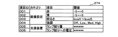
- FIG. 5 is an explanatory diagram showing an example of the record layout of the threshold value DB 274.
- the threshold value DB 274 includes an item ID column, a category column, an item column, and a threshold value column.
- the item ID column stores the ID of the item uniquely specified in order to identify each item.
- the category column stores item type information.
- the item column stores the name of the item.
- the threshold value column stores the threshold value of the item.
- FIG. 6 is an explanatory diagram illustrating a process of monitoring a system abnormality.
- the control unit 21 of the processor 2 acquires an endoscope image taken by using the first system information from the endoscope 1.
- the first system information is the system information set in the endoscopic system in use (currently).
- the user can change the first system information by operating a keyboard or the like connected to the processor 2.
- the control unit 21 of the processor 2 stores the first system information in the system information DB 273 of the large-capacity storage unit 27. Since the items included in the first system information are the same as the items included in the system information described above, the description thereof will be omitted.
- the control unit 21 calculates the parameters based on the acquired endoscopic image.
- the parameters include color tone parameters, brightness parameters, spatial frequency parameters or noise amount parameters of the endoscopic image.
- the color tone parameter may be, for example, a value obtained by averaging the pixel values of R, G, or B of each pixel constituting the endoscopic image within the entire screen or a predetermined range in the screen, or the pixel value in the image. It may be the frequency of occurrence of pixel values based on a histogram showing the overall distribution of. R is red, G is green, and B is the pixel value of the blue sub-pixel.
- the luminance parameter may be, for example, the luminance in each pixel, that is, ((R + G + B) / 3), or the number of pixels corresponding to each luminance value based on the luminance histogram showing the luminance distribution of the pixels in the image. And the degree of bias of the distribution may be used.
- the spatial frequency parameter may be, for example, the frequency distribution of the image data obtained by the Fourier transform.
- Spatial frequency represents the number of repetitions of the pattern included in the unit length.
- the spatial frequency represents the number of repetitions of sinusoidal shading changes per unit length for a two-dimensional image. In this case, the spatial frequency becomes high at a place where the light and shade changes rapidly, and becomes low at a place where the light and shade changes slowly.
- the noise amount parameter is the amount of image noise and is represented by the standard deviation (SD: Standard Deviation), which is the square root of the variance.
- SD Standard Deviation
- the image noise is a high-frequency component having a high spatial frequency among the non-uniform brightness generated in the captured image.
- the standard deviation is represented by a value that indicates how the data is scattered.
- the control unit 21 acquires the model information of the endoscope 1.
- the model information includes the series and model number of the endoscope, the number of pixels of the image sensor, the target site information (for example, the upper gastrointestinal tract), and the like.
- the control unit 21 acquires model information from the endoscope 1 (scope).
- the control unit 21 acquires the model number from the endoscope 1.
- the control unit 21 may acquire model information corresponding to the acquired model number from the storage unit 22.
- the control unit 21 uses a site identification model 271 that outputs an identification result that identifies the site of the subject when the parameters calculated based on the endoscopic image and the acquired model information are input. Identify the site.
- the site identification process will be described later.
- the control unit 21 uses a system information output model 272 that outputs the second system information when the parameters calculated based on the endoscopic image, the acquired model information, and the identified part of the subject are input. Acquires (outputs) the second system information. Since the items included in the second system information are the same as the items included in the first system information, the description thereof will be omitted. The second system information acquisition process will be described later.
- the control unit 21 acquires the first system information from the system information DB 273 of the large-capacity storage unit 27.
- the control unit 21 compares the acquired first system information with the second system information to determine the difference. Specifically, the control unit 21 obtains the first system information with respect to the red intensity, the blue intensity, the brightness setting information, the emphasis mode setting information, the lamp aperture setting information, and the voltage or current to the lamp of the image. Each item is compared with each item of the corresponding second system information.
- control unit 21 determines that the two match, it determines that no abnormality has been detected. When it is determined that the two do not match, the control unit 21 determines whether or not the system settings can be changed. Specifically, the control unit 21 acquires the threshold value of system information from the threshold value DB 274 of the large-capacity storage unit 27. The control unit 21 determines whether or not each item of the second system information is within the threshold value based on the acquired threshold value.
- the control unit 21 When it is determined that each item or a part of the items of the second system information is out of the threshold range, the control unit 21 outputs a message including the fact that the difference has been detected to the display device 3.
- the control unit 21 determines that each item of the second system information is within the threshold range, the control unit 21 changes the system setting by using the first system information. For example, as an example in which the red strength of the first system information is set to "2”, when the control unit 21 determines that the red strength of the second system information is "3", the red strength of the system is set. To "2".
- control unit 21 determines that the value of the lamp diaphragm of the second system information is lower than the value of the lamp diaphragm of the first system information, an abnormality in the light source system causes a loss in the amount of light from the normal state. there is a possibility.
- the control unit 21 changes the value of the lamp diaphragm of the system to the value of the lamp diaphragm of the first system information.
- control unit 21 determines that the system setting change is successful, the control unit 21 outputs a message including the fact that the change is successful to the display device 3. Before changing the system settings, a confirmation message for changing the settings may be output to the user (doctor). In this case, the system setting change is executed with the consent of the user. When the control unit 21 determines that the system setting change has failed, the control unit 21 outputs a message including the change failure to the display device 3.
- FIG. 7 is an explanatory diagram illustrating the site identification model 271.
- the site identification model 271 is used as a program module that is a part of artificial intelligence software.
- the site identification model 271 is a classifier for which a neural network has been constructed (generated) in which parameters calculated based on an endoscopic image and model information are input and the result of predicting the site of a subject is output. ..
- the neural network is, for example, a CNN (Convolutional Neural Network), which is an input layer that accepts inputs of parameters and model information calculated based on an endoscopic image, and an output layer that outputs a result of predicting a part of a subject. And an intermediate layer that has been trained by backpropagation.
- Each layer has one or more neurons (nodes), and each neuron has a value. Then, neurons between one layer and the next layer are connected by edges, and each edge has variables (or parameters) such as weights and biases.
- the value of the neuron in each layer is obtained by executing a predetermined operation based on the value of the neuron in the previous layer and the weight of the edge. Then, when the input data is input to the neurons of the input layer, the values of the neurons of the next layer are obtained by a predetermined calculation, and further, the values of the neurons of the next layer are obtained by using the data obtained by the calculation as an input. It is obtained by a predetermined calculation of the layer. Then, the value of the neuron in the output layer, which is the final layer, becomes the output data with respect to the input data.
- the site identification model 271 will be described as a CNN, but the site identification model 271 is not limited to the CNN, and is a neural network other than the CNN, R-CNN (Regions with Convolutional Neural Networks), SVM. It may be a trained model constructed by any learning algorithm such as (Support Vector Machine), Bayesian network, or regression tree.
- the control unit 21 compares the identification result output from the output layer with the labeled information of the part with respect to the teacher data, that is, the correct answer value, and the intermediate layer so that the output value from the output layer approaches the correct answer value.
- the teacher data is data generated by associating the name of the part (for example, the large intestine) with the parameters calculated based on the endoscope image and the model information of the endoscope 1.
- the variable is, for example, a weight between neurons (coupling coefficient), a coefficient of an activation function used in each neuron, and the like.
- the method of optimizing the variables is not particularly limited, but for example, the control unit 21 optimizes various variables by using the backpropagation method.
- the control unit 21 performs the above processing on the parameters and model information included in the teacher data, and generates the part identification model 271.
- the generation process of the site identification model 271 is not limited to the above-mentioned process.
- the control unit 21 may generate a site identification model for each model of endoscope.
- a large intestine identification model for identifying the large intestine may be generated.
- the site identification model 271 is generated by the processor 2
- the present invention is not limited to this.
- the site identification model 271 may be generated by an external device (for example, a server or the like).
- control unit 21 of the processor 2 may download and install the part identification model 271 generated by the external device by the communication unit 29. Further, the control unit 21 may read and install the site identification model 271 generated by the external device from the portable storage medium 2a or the semiconductor memory 2b via the reading unit 26. The update process of the site identification model 271 may be performed by the processor 2 or by an external device.
- the control unit 21 acquires an endoscope image from the endoscope 1, the control unit 21 identifies the site of the subject using the site identification model 271.
- the input layer of the site identification model 271 accepts inputs of the parameters "x1 to xn" calculated based on the endoscopic image and the model information "x (n + 1)".
- x1 to xn indicate the color tone parameter, the luminance parameter, the spatial frequency parameter, or the noise amount parameter of the endoscopic image described above.
- x (n + 1) indicates model information including the endoscope series, model number, number of pixels of the image sensor, or target site information.
- the average value of each pixel value of R, G or B of each pixel constituting the endoscopic image, the degree of bias of the distribution based on the histogram, or the spatial frequency is input to the part identification model 271. If this is the case, it will have a great effect on the identification result of the site of the subject.
- the intermediate layer extracts the features of the input information by changing the number of dimensions of the input information input from the input layer.
- the intermediate layer is then predicted to be at each site of the subject according to the extracted features by the fully connected layer whose parameters have been learned by backpropagation.
- the prediction result is output to the output layer having a plurality of neurons. As shown, the probability value in the mouth is 0.02, the probability value in the esophagus is 0.03, the probability value in the stomach is 0.02, the probability value in the small intestine is 0.03, and The prediction result that the probability value of the large intestine is 0.9 is output.
- the part identification process is not limited to the process of identifying the part by the above-mentioned machine learning.
- the control unit 21 of the processor 2 uses a local feature extraction method such as A-KAZE (Accelerated KAZE) or SIFT (Scale Invariant Feature Transform) based on the change in color or fold of each part from the endoscopic image.
- the site may be identified.
- the control unit 21 of the processor 2 may accept the identification result of the doctor identifying the site of the subject based on the medical expertise by the operation input unit 23.
- FIG. 8 is an explanatory diagram illustrating the system information output model 272.
- the system information output model 272 is used as a program module that is a part of artificial intelligence software.
- the system information output model 272 inputs the parameters calculated based on the endoscopic image, the model information and the part of the subject (part identification result) output from the part identification model 271, and the second system information.
- This is an output device for which a neural network has been constructed (generated) that outputs the result of predicting.
- the neural network is CNN
- system information output model 272 is described as being a CNN, but the system information output model 272 is not limited to the CNN, and is a neural network other than the CNN, R-CNN, SVM, Bayesian network, or. It may be a trained model constructed by an arbitrary learning algorithm such as a regression tree.
- the control unit 21 compares the prediction result output from the output layer with the labeled information of each item of the system information, that is, the correct answer value with respect to the teacher data, so that the output value from the output layer approaches the correct answer value.
- the variables used for arithmetic processing in the intermediate layer are optimized.
- the teacher data is data generated by associating each item of system information with the parameters calculated based on the endoscope image, the model information of the endoscope 1, and the part of the subject.
- the control unit 21 performs the above processing on the parameters and various information included in the teacher data, and generates the system information output model 272.
- the system information output model 272 generation process is not limited to the above-mentioned process.
- the control unit 21 may generate a system information output model for each model of the endoscope, or may generate a system information output model for each part of the subject.
- a system information output model may be generated for each item of system information. For example, a color intensity determination model for determining the intensity of red or blue of an image, a luminance determination model for determining brightness, or the like may be generated.
- system information output model 272 is generated by the processor 2
- the present invention is not limited to this.
- the system information output model 272 may be generated by an external device.
- the control unit 21 acquires the site of the subject using the site identification model 271
- the control unit 21 acquires the second system information using the system information output model 272.
- the input layer of the system information output model 272 was output from the parameters "x1 to xn" calculated based on the endoscopic image, the model information "x (n + 1)", and the site identification model 271. Accepts the input of the part "x (n + 2)" of the subject. Since x1 to xn and x (n + 1) are the same as the above-mentioned input information, the description thereof will be omitted.
- x (n + 2) indicates the site of the subject (for example, the large intestine).
- the output result of the second system information is Has a great impact.
- the intermediate layer extracts the features of the input information by changing the number of dimensions of the input information input from the input layer. After that, the intermediate layer predicts the probability of each item of the second system information according to the extracted features by the fully connected layer whose parameters are learned by backpropagation. The prediction result is output to the output layer having a plurality of neurons. As shown in the figure, the prediction result corresponding to the highest probability in each item of the second system information is output. Not limited to the output result described above, all probability values of each item of system information may be output.
- the probability value of the combination of each item of the system information may be output.
- a probability value of "red intensity: 3, blue intensity: 2, brightness: Level 2, lamp diaphragm: 128, voltage to lamp: 100v" may be output.
- the combination corresponding to the highest probability among the probability values of the combinations may be output as the prediction result.
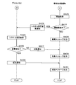
- the control unit 21 of the processor 2 acquires an endoscope image taken by using the first system information from the endoscope 1 (step S201).
- the control unit 21 calculates the parameters based on the acquired endoscopic image (step S202).
- the control unit 21 acquires model information including a series of endoscopes, a model number, the number of pixels of an image sensor, target site information, and the like stored in the endoscope 1 in advance (step S203).
- the control unit 21 uses a site identification model 271 that outputs an identification result that identifies the site of the subject when the parameters calculated based on the endoscopic image and the acquired model information are input. Identify the site (step S204).
- the control unit 21 is a system information output model that outputs the second system information when the parameters calculated based on the endoscopic image, the acquired model information, and the part of the subject identified by the part identification model 271 are input.
- the second system information is acquired by using 272 (step S205).
- the control unit 21 transmits the red intensity, the blue intensity, the brightness setting information, the emphasis mode setting information, the lamp aperture setting information, and the voltage or current to the lamp from the system information DB 273 of the large-capacity storage unit 27. Acquire the first system information including the first system information (step S206). The control unit 21 compares each item of the acquired first system information with each item of the corresponding second system information to determine the difference (step S207).
- control unit 21 determines that there is no difference between the first system information and the second system information (NO in step S207).
- the control unit 21 returns to step S201.
- the control unit 21 determines that there is a difference between the first system information and the second system information (YES in step S207)
- the control unit 21 acquires the threshold value of the system information from the threshold value DB 274 of the large capacity storage unit 27 (step S208). ..
- the control unit 21 determines whether or not each item of the second system information is within the threshold value based on the acquired threshold value (step S209).
- the control unit 21 When it is determined that each item or a part of the items of the second system information is out of the threshold range (NO in step S209), the control unit 21 outputs an abnormal message including the fact that the difference has been detected to the display device 3. (Step S210).
- the display device 3 displays an abnormal message output from the processor 2 (step S301).
- the control unit 21 of the processor 2 determines that each item of the second system information is within the threshold range (YES in step S209), the control unit 21 changes the system setting using the first system information (step S211). ..
- the control unit 21 determines whether or not the system setting change has been successful (step S212). When the control unit 21 determines that the system setting change has not been successful (NO in step S212), the control unit 21 outputs a message including the change failure to the display device 3 (step S213). The display device 3 displays a message output from the processor 2 to the effect that the change has failed (step S302).
- control unit 21 of the processor 2 determines that the system setting change is successful (YES in step S212)
- the control unit 21 outputs a message including the fact that the change is successful to the display device 3 (step S214).
- the control unit 21 returns to step S201.
- the display device 3 displays a message output from the processor 2 to the effect that the change is successful (step S303).
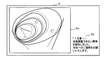
- FIG. 11A and 11B are schematic views of an endoscopic image displaying a message on the display device 3.
- Reference numeral 3a is an observation screen (area) of the endoscope.
- Reference numeral 3b is an area for displaying a message.
- the display device 3 displays the endoscopic image output from the processor 2 on 3a, and displays the message output from the processor 2 on 3b.
- the notification display screen is not limited to the layout described above.
- the message may be displayed on the observation screen 3a of the endoscope.
- FIG. 11A shows an example in which, when the system setting change is successful, a message including the fact that the change is successful is displayed.
- FIG. 11B shows an example in which, when the system setting change fails, a message including the change failure is displayed.
- the learning model by monitoring the system abnormality using the learning model, it is possible to infer the factors that affect the image quality, so that the system settings can be changed according to the inferred factors. ..
- the second embodiment relates to a form for identifying a site of a subject using an image feature amount.
- the description of the contents overlapping with the first embodiment will be omitted.
- the image feature amount is a numerical value of the image geometry of each region on the image, the image value, and the feature parameter calculated from these, and is obtained by applying an image processing method.
- the image feature amount may be the average value of the pixel values of R, G, or B of each pixel constituting the image, the average value of the brightness, the degree of bias of the brightness, and the like.
- the identification result for identifying the site of the subject is output, but the present invention is not limited to this.
- a process of outputting an identification result that identifies a part of a subject when an endoscopic image taken by using the first system information is directly input to the part identification model 271 will be described.
- FIG. 12 is an explanatory diagram illustrating the site identification model 271 of the second embodiment.
- the site identification model 271 is a classifier for which a neural network has been constructed that inputs an endoscopic image taken by using the first system information and outputs a result of predicting a site of a subject.
- the neural network is, for example, a CNN, and has an input layer that accepts input of an endoscopic image, an output layer that outputs a result of predicting a part of a subject, and an intermediate layer that has been learned by backpropagation.
- the input layer has a plurality of neurons that accept the input of the pixel value of each pixel included in the endoscopic image, and passes the input pixel value to the intermediate layer.
- the intermediate layer has a plurality of neurons for extracting the image features of the endoscopic image, and the extracted image features are passed to the output layer.
- the intermediate layer has an endoscopic image in which a convolution layer that convolves the pixel values of each pixel input from the input layer and a pooling layer that maps the pixel values convoluted by the convolution layer are alternately connected. Finally, the feature amount of the image is extracted while compressing the pixel information of.
- the intermediate layer then predicts the probability that the endoscopic image is at each site of the subject by the fully connected layer whose parameters have been learned by backpropagation. The prediction result is output to the output layer having a plurality of neurons.
- the endoscopic image may be input to the input layer after the feature amount is extracted by passing through the convolution layer and the pooling layer which are alternately connected.
- the image input to the site identification model 271 is not limited to the endoscopic image.
- the control unit 21 shows a histogram image showing the overall distribution of pixel values in the image, a brightness histogram image showing the distribution of the brightness of the pixels in the image, or a spatial frequency based on the endoscopic image. Generate a graph image or the like.
- the control unit 21 inputs the generated graph image into the site identification model 271 that has been learned by deep learning using the graph image included in the teacher data, and outputs the identification result of identifying the site of the subject.
- the input layer of the system information output model 272 receives the input of the pixel value of each pixel included in the endoscopic image and the part of the subject output from the part identification model 271 and receives the input to the intermediate layer. hand off.
- the intermediate layer extracts the image feature amount of the endoscopic image from the pixel value of each passed pixel.
- the intermediate layer predicts the probability of each item of system information based on the part of the subject and the extracted image feature amount, and outputs the prediction result to the output layer.
- the third embodiment relates to a mode in which the information processing device 4 monitors a system abnormality by using artificial intelligence.
- the description of the contents overlapping with the first and second embodiments will be omitted.
- the part identification process and the second system information output process are performed by the processor 2 using the learning model, but in the present embodiment, the above-described process is performed by the information processing device 4. ..
- the information processing device 4 is an information processing device that constructs a learning model, determines a system abnormality using the learning model, processes various information, stores, and transmits / receives.
- the information processing device 4 is, for example, a server device, a personal computer, a general-purpose tablet PC (personal computer), or the like.
- FIG. 13 is a schematic view showing a configuration example of the endoscope system of the third embodiment.
- the contents overlapping with FIGS. 1 and 3 are designated by the same reference numerals and the description thereof will be omitted.
- the system shown in FIG. 13 includes an endoscope 1, a processor 2, a display device 3, and an information processing device 4. Each device transmits and receives electric signals, video signals, etc. via a connector.
- the processor 2 is captured by using the first system information set by the endoscope system in use, the model information of the endoscope stored in the endoscope 1 in advance, and the first system information. Acquire an endoscopic image.
- the processor 2 outputs the acquired first system information, model information, and endoscopic image to the information processing device 4.
- the control unit 21 of the information processing device 4 calculates the parameters based on the endoscopic image output from the processor 2.
- the control unit 21 identifies the part of the subject by using the part identification model 271 that outputs the identification result of identifying the part of the subject when the parameters calculated based on the endoscopic image and the model information are input. To do. Since the site identification process is the same as that of the first or second embodiment, the description thereof will be omitted.
- the control unit 21 outputs a system information output model 272 that outputs the second system information when the parameters calculated based on the endoscopic image and the model information and the part of the subject identified by the part identification model 271 are input. It is used to acquire the second system information. Since the second system information acquisition process is the same as that of the first or second embodiment, the description thereof will be omitted.
- the control unit 21 compares each item of the first system information with each item of the corresponding second system information to determine the difference. When the control unit 21 determines that there is a difference between the first system information and the second system information, the control unit 21 acquires the threshold value of the system information from the threshold value DB 274 of the large-capacity storage unit 27. The control unit 21 determines whether or not each item of the second system information is within the threshold value based on the acquired threshold value.
- the control unit 21 When it is determined that each item or a part of the items of the second system information is out of the threshold range, the control unit 21 outputs an abnormal message including the fact that the difference has been detected to the display device 3. When the control unit 21 determines that each item of the second system information is within the threshold range, the control unit 21 outputs a notification of the system setting change to the processor 2. The processor 2 changes the system settings by using the first system information in response to the notification of the system setting change output from the information processing device 4.
- the processor 2 outputs the result (for example, success or failure) of the system setting change to the information processing device 4.
- the control unit 21 of the information processing device 4 outputs an appropriate message to the display device 3 according to the result of the setting change output from the processor 2.
- the 14 and 15 are flowcharts showing a processing procedure when monitoring a system abnormality with the information processing device 4.
- the processor 2 acquires the first system information stored in the endoscope system during normal use (step S221).
- the control unit 21 acquires the model information of the endoscope stored in the endoscope 1 in advance (step S222).
- the processor 2 acquires an endoscope image taken by using the first system information from the endoscope 1 (step S223).
- the processor 2 outputs the acquired first system information, model information, and endoscopic image to the information processing device 4 (step S224).
- the processor 2 returns to step S221.
- the control unit 21 of the information processing device 4 stores the first system information output from the processor 2 in the system information DB 273 of the large-capacity storage unit 27 (step S421).
- the processor 2 outputs the first system information and the model information to the information processing device 4, but the present invention is not limited to this.
- the first system information and the model information may be stored in advance in the storage unit 22 or the large-capacity storage unit 27 of the information processing device 4.
- the control unit 21 of the information processing device 4 calculates the parameters based on the endoscopic image output from the processor 2 (step S422).
- the control unit 21 uses a site identification model 271 that outputs an identification result that identifies the site of the subject when the parameters calculated based on the endoscopic image and the model information output from the processor 2 are input. , Identify the site of the subject (step S423).
- the control unit 21 outputs a system information output model 272 that outputs the second system information when the parameters calculated based on the endoscopic image and the model information and the part of the subject identified by the part identification model 271 are input.
- the second system information is acquired by using (step S424).
- the control unit 21 compares each item of the first system information with each item of the corresponding second system information and determines the difference (step S425). When the control unit 21 determines that there is no difference between the first system information and the second system information (NO in step S425), the control unit 21 returns to step S421. When the control unit 21 determines that there is a difference between the first system information and the second system information (YES in step S425), the control unit 21 acquires the threshold value of the system information from the threshold value DB 274 of the large-capacity storage unit 27 (step S426). ..
- the control unit 21 determines whether or not each item of the second system information is within the threshold value based on the acquired threshold value (step S427). When it is determined that each item or a part of the items of the second system information is out of the threshold range (NO in step S427), the control unit 21 outputs an abnormal message including the fact that the difference has been detected to the display device 3. (Step S428).
- control unit 21 determines that each item of the second system information is within the threshold range (YES in step S427), the control unit 21 outputs a notification of the system setting change to the processor 2 (step S429).
- the processor 2 changes the system setting by using the first system information in response to the notification of the system setting change output from the information processing device 4 (step S225).
- the processor 2 determines whether or not the system setting change has been successful (step S226). When the processor 2 determines that the system setting change has not been successful (NO in step S226), the processor 2 outputs a notification of the change failure to the information processing device 4 (step S227).
- the control unit 21 of the information processing device 4 outputs a message including the change failure to the display device 3 in response to the change failure notification output from the processor 2 (step S430).
- the processor 2 determines that the system setting change is successful (YES in step S226)
- the processor 2 outputs a notification of the change success to the information processing device 4 (step S228).
- the control unit 21 of the information processing device 4 outputs a message including the change success to the display device 3 in response to the change success notification output from the processor 2 (step S431).
- FIG. 16 is a functional block diagram showing the operation of the processors 2 of the first and second embodiments.
- the control unit 21 executes the control program 2P
- the processor 2 operates as follows.
- the functional block diagram showing the operation is similarly applied to the information processing device 4 of the third embodiment.
- the image acquisition unit 20a acquires an endoscopic image taken using the first system information.
- the calculation unit 20b calculates the parameters based on the endoscopic image acquired by the image acquisition unit 20a.
- the first learning model 20c outputs an identification result that identifies the site of the subject when the parameter calculated by the calculation unit 20b is input.
- the second learning model 20d outputs the second system information when the parameters calculated by the calculation unit 20b and the identification result output by the first learning model 20c are input.
- the determination unit 20e determines the difference between the second system information output by the second learning model 20d and the first system information.
- the change unit 20f changes the system settings based on the determination result determined by the determination unit 20e.
- the model information acquisition unit 20g acquires model information of the endoscope.
- the fourth embodiment is as described above, and the other parts are the same as those of the first to third embodiments. Therefore, the corresponding parts are designated by the same reference numerals and detailed description thereof will be omitted.
Landscapes
- Health & Medical Sciences (AREA)
- Engineering & Computer Science (AREA)
- Life Sciences & Earth Sciences (AREA)
- Surgery (AREA)
- Medical Informatics (AREA)
- General Health & Medical Sciences (AREA)
- Public Health (AREA)
- Nuclear Medicine, Radiotherapy & Molecular Imaging (AREA)
- Radiology & Medical Imaging (AREA)
- Biomedical Technology (AREA)
- Physics & Mathematics (AREA)
- Animal Behavior & Ethology (AREA)
- Heart & Thoracic Surgery (AREA)
- Molecular Biology (AREA)
- Pathology (AREA)
- Optics & Photonics (AREA)
- Biophysics (AREA)
- Veterinary Medicine (AREA)
- Signal Processing (AREA)
- Evolutionary Computation (AREA)
- Artificial Intelligence (AREA)
- Business, Economics & Management (AREA)
- General Business, Economics & Management (AREA)
- Epidemiology (AREA)
- Primary Health Care (AREA)
- Quality & Reliability (AREA)
- Computer Vision & Pattern Recognition (AREA)
- General Physics & Mathematics (AREA)
- Theoretical Computer Science (AREA)
- Endoscopes (AREA)
- Instruments For Viewing The Inside Of Hollow Bodies (AREA)
Abstract
A processor (2) according to one aspect of the present invention is characterized by being provided with: an image acquisition unit which acquires an endoscopic image captured by using first system information; a calculation unit which calculates a parameter on the basis of the endoscopic image acquired by the image acquisition unit; a first learning model (271) which outputs an identification result obtained by identifying a part of a patient in the case when the parameter calculated by the calculation unit is inputted; a second learning model (272) which outputs second system information in the case when the parameter calculated by the calculation unit and the identification result outputted from the first learning model (271) are inputted; and a determination unit which determines the difference between the second system information outputted from the second learning model (272) and the first system information.
Description
本発明は、内視鏡用プロセッサ、内視鏡システム、情報処理装置、プログラム及び情報処理方法に関する。
The present invention relates to an endoscope processor, an endoscope system, an information processing device, a program, and an information processing method.
近年、内視鏡検査における検出精度を向上するための各種の画像処理技術がある。例えば、特許文献1には、内視鏡画像に付される病変部を示す印と内視鏡画像との位置ずれが防止される画像処理装置が開示されている。
In recent years, there are various image processing techniques for improving the detection accuracy in endoscopy. For example, Patent Document 1 discloses an image processing device that prevents misalignment between a mark indicating a lesion portion attached to an endoscopic image and an endoscopic image.
しかしながら、特許文献1の発明では、画質に影響を与えるようなシステム異常が発生した際に、異常の要因(例えば、画像設定、光学系、光源または電気回路等)を正しく特定することができないおそれがある。
However, in the invention of Patent Document 1, when a system abnormality that affects the image quality occurs, the cause of the abnormality (for example, image setting, optical system, light source, electric circuit, etc.) may not be correctly identified. There is.
一つの側面では、学習済みの学習モデルを用いてシステム異常の要因を特定することが可能な内視鏡用プロセッサ等を提供することを目的とする。
One aspect is to provide an endoscope processor or the like that can identify the cause of a system abnormality using a learned learning model.
一つの側面に係る内視鏡用プロセッサは、第1システム情報を使用して撮影された内視鏡画像を取得する画像取得部と、前記画像取得部が取得した内視鏡画像に基づいてパラメータを算出する算出部と、前記算出部が算出したパラメータを入力した場合に被検体の部位を識別した識別結果を出力する第1学習モデルと、前記算出部が算出したパラメータと、前記第1学習モデルが出力した識別結果とを入力した場合に第2システム情報を出力する第2学習モデルと、前記第2学習モデルが出力した第2システム情報と、前記第1システム情報との差異を判定する判定部とを備えることを特徴とする。
The endoscope processor according to one aspect has an image acquisition unit that acquires an endoscopic image taken by using the first system information and parameters based on the endoscopic image acquired by the image acquisition unit. A calculation unit that calculates, a first learning model that outputs an identification result that identifies a part of a subject when a parameter calculated by the calculation unit is input, a parameter calculated by the calculation unit, and the first learning. Determine the difference between the second learning model that outputs the second system information when the identification result output by the model is input, the second system information output by the second learning model, and the first system information. It is characterized by including a determination unit.
一つの側面では、学習済みの学習モデルを用いてシステム異常の要因を特定することが可能となる。
On one side, it is possible to identify the cause of system abnormalities using a trained learning model.
以下、本発明をその実施形態を示す図面に基づいて詳述する。
Hereinafter, the present invention will be described in detail with reference to the drawings showing the embodiments thereof.
(実施形態1)
実施形態1は、人工知能(AI:artificial intelligence)を用いてシステム異常を監視する形態に関する。図1は、内視鏡システムの構成例を示す模式図である。図1に示すシステムは、被検体の体内に挿入されて撮影を行い、観察対象の映像信号を出力する内視鏡1、内視鏡1が出力した映像信号を内視鏡画像に変換する内視鏡用プロセッサ2、及び内視鏡画像等を表示する表示装置3を含む。各装置はコネクタを介して電気信号、映像信号等の送受信を行う。 (Embodiment 1)
The first embodiment relates to a mode in which a system abnormality is monitored by using artificial intelligence (AI). FIG. 1 is a schematic view showing a configuration example of an endoscope system. The system shown in FIG. 1 is inserted into the body of a subject to take an image, and theendoscope 1 outputs an image signal to be observed, and the image signal output by the endoscope 1 is converted into an endoscope image. It includes a processor 2 for an endoscope and a display device 3 for displaying an endoscopic image or the like. Each device transmits and receives electric signals, video signals, etc. via a connector.
実施形態1は、人工知能(AI:artificial intelligence)を用いてシステム異常を監視する形態に関する。図1は、内視鏡システムの構成例を示す模式図である。図1に示すシステムは、被検体の体内に挿入されて撮影を行い、観察対象の映像信号を出力する内視鏡1、内視鏡1が出力した映像信号を内視鏡画像に変換する内視鏡用プロセッサ2、及び内視鏡画像等を表示する表示装置3を含む。各装置はコネクタを介して電気信号、映像信号等の送受信を行う。 (Embodiment 1)
The first embodiment relates to a mode in which a system abnormality is monitored by using artificial intelligence (AI). FIG. 1 is a schematic view showing a configuration example of an endoscope system. The system shown in FIG. 1 is inserted into the body of a subject to take an image, and the
内視鏡1は、先端部に撮像素子がある挿入部を被検体の体内に挿入し、診断または治療を行う器具である。内視鏡1は、先端にある撮像素子を用いて捉えた撮影画像をプロセッサ2に転送する。
The endoscope 1 is an instrument for diagnosing or treating by inserting an insertion part having an image sensor at the tip into the body of a subject. The endoscope 1 transfers a captured image captured by the image sensor at the tip to the processor 2.
内視鏡用プロセッサ2は、内視鏡1の先端にある撮像素子から取り込まれた撮像画像に対して画像処理を行い、内視鏡画像を生成して表示装置3に出力する情報処理装置である。また、以下では簡潔のため、内視鏡用プロセッサ2をプロセッサ2と読み替える。
The endoscope processor 2 is an information processing device that performs image processing on an image captured from an imaging element at the tip of the endoscope 1, generates an endoscope image, and outputs the endoscopic image to the display device 3. is there. Further, in the following, for the sake of brevity, the endoscope processor 2 will be read as the processor 2.
表示装置3は、液晶ディスプレイ又は有機EL(electroluminescence)ディスプレイ等であり、プロセッサ2から出力された内視鏡画像等を表示する。
The display device 3 is a liquid crystal display, an organic EL (electroluminescence) display, or the like, and displays an endoscopic image or the like output from the processor 2.
図2は、内視鏡1の外観図である。内視鏡1は、撮像素子11、処置具挿入チャネル12、操作部13及びコネクタ14を含む。撮像素子11は、内視鏡1の先端部に設置された、例えばCCD(Charge Coupled Device)イメージセンサ、CMD(Charge Modulation Device)イメージセンサまたはCMOS(Complementary Metal Oxide Semiconductor)イメージセンサであり、入射光を光電変換する。光電変換により生成された電気信号には、図示しない信号処理回路によりA/D変換、ノイズ除去などの信号処理が施され、プロセッサ2に出力される。
FIG. 2 is an external view of the endoscope 1. The endoscope 1 includes an image sensor 11, a treatment tool insertion channel 12, an operation unit 13, and a connector 14. The image sensor 11 is, for example, a CCD (Charge Coupled Device) image sensor, a CMD (Charge Modulation Device) image sensor, or a CMOS (Complementary Metal Oxide Semiconductor) image sensor installed at the tip of the endoscope 1, and is an incident light. Is photoelectrically converted. The electric signal generated by the photoelectric conversion is subjected to signal processing such as A / D conversion and noise removal by a signal processing circuit (not shown), and is output to the processor 2.
処置具挿入チャネル12は、処置具を通すためのチャンネルである。処置具は、例えば把持具、生検針、鉗子、スネア、クランプ、ハサミ、メス、切開器具、内視鏡ステープラ、組織ループ、クリップアプライヤ、縫合糸送達器具、またはエネルギーによる組織凝固器具若しくは組織切断器具である。操作部13にはレリーズボタン、内視鏡の先端を曲げるためのアングルノブ等が設けられ、例えば送気、送水、送ガス等の周辺機器の操作指示信号の入力を受け付ける。コネクタ14は、プロセッサ2に接続される。
The treatment tool insertion channel 12 is a channel for passing the treatment tool. Treatment tools include, for example, grippers, biopsy needles, forceps, snares, clamps, scissors, scalpels, incision instruments, endoscopic staplers, tissue loops, clip pliers, suture delivery instruments, or energy-based tissue coagulation instruments or tissue cutting. It is an instrument. The operation unit 13 is provided with a release button, an angle knob for bending the tip of the endoscope, and the like, and receives input of operation instruction signals of peripheral devices such as air supply, water supply, and gas supply. The connector 14 is connected to the processor 2.
図3は、プロセッサ2の構成例を示すブロック図である。プロセッサ2は、制御部21、記憶部22、操作入力部23、出力部24、光源制御部25、読取部26、大容量記憶部27、光源28及び通信部29を含む。各構成はバスBで接続されている。
FIG. 3 is a block diagram showing a configuration example of the processor 2. The processor 2 includes a control unit 21, a storage unit 22, an operation input unit 23, an output unit 24, a light source control unit 25, a reading unit 26, a large-capacity storage unit 27, a light source 28, and a communication unit 29. Each configuration is connected by bus B.
制御部21は、CPU(Central Processing Unit)、MPU(Micro-Processing Unit)、GPU(Graphics Processing Unit)等の演算処理装置を含み、記憶部22に記憶された制御プログラム2Pを読み出して実行することにより、プロセッサ2に係る種々の情報処理、制御処理等を行う。なお、図3では制御部21を単一のプロセッサであるものとして説明するが、マルチプロセッサであっても良い。
The control unit 21 includes arithmetic processing units such as a CPU (Central Processing Unit), an MPU (Micro-Processing Unit), and a GPU (Graphics Processing Unit), and reads and executes a control program 2P stored in the storage unit 22. Performs various information processing, control processing, and the like related to the processor 2. Although the control unit 21 is described as a single processor in FIG. 3, it may be a multiprocessor.
記憶部22は、RAM(Random Access Memory)、ROM(Read Only Memory)等のメモリ素子を含み、制御部21が処理を実行するために必要な制御プログラム2P又はデータ等を記憶している。また、記憶部22は、制御部21が演算処理を実行するために必要なデータ等を一時的に記憶する。操作入力部23は、例えばタッチパネル、各種スイッチ等の入力デバイスによって構成され、これらの入力デバイスに対する外部からの操作に応じて発生した入力信号を制御部21に入力する。出力部24は、制御部21の制御の下で、表示用の画像信号及び各種の情報を表示装置3に出力し、画像及び情報を表示させる。
The storage unit 22 includes memory elements such as RAM (RandomAccessMemory) and ROM (ReadOnlyMemory), and stores the control program 2P or data required for the control unit 21 to execute the process. In addition, the storage unit 22 temporarily stores data and the like necessary for the control unit 21 to execute arithmetic processing. The operation input unit 23 is composed of input devices such as a touch panel and various switches, and inputs an input signal generated in response to an external operation on these input devices to the control unit 21. Under the control of the control unit 21, the output unit 24 outputs an image signal for display and various types of information to the display device 3 to display the image and information.
光源制御部25は、LED等のオン/オフ、LED等の駆動電流及び駆動電圧の調整によって照明光の発光量を制御する。また、光源制御部25は、光学フィルタの変更等によって、照明光の波長帯域を制御する。光源制御部25は、各LEDの点灯や消灯、及び点灯時の発光量等を独立に制御することによって、照明光の発光タイミング、発光期間、光量、及び分光スペクトルの調節を行う。
The light source control unit 25 controls the amount of light emitted from the illumination light by turning on / off the LED and the like, adjusting the drive current and the drive voltage of the LED and the like. Further, the light source control unit 25 controls the wavelength band of the illumination light by changing the optical filter or the like. The light source control unit 25 adjusts the emission timing, emission period, light amount, and spectral spectrum of the illumination light by independently controlling the lighting and extinguishing of each LED and the amount of light emitted at the time of lighting.
読取部26は、CD(Compact Disc)-ROM又はDVD(Digital Versatile Disc)-ROMを含む可搬型記憶媒体2aを読み取る。制御部21が読取部26を介して、制御プログラム2Pを可搬型記憶媒体2aより読み取り、大容量記憶部27に記憶しても良い。また、ネットワークN等を介して他のコンピュータから制御部21が制御プログラム2Pをダウンロードし、大容量記憶部27に記憶しても良い。さらにまた、半導体メモリ2bから、制御部21が制御プログラム2Pを読み込んでも良い。
The reading unit 26 reads a portable storage medium 2a including a CD (Compact Disc) -ROM or a DVD (Digital Versatile Disc) -ROM. The control unit 21 may read the control program 2P from the portable storage medium 2a via the reading unit 26 and store it in the large-capacity storage unit 27. Further, the control unit 21 may download the control program 2P from another computer via the network N or the like and store it in the large-capacity storage unit 27. Furthermore, the control unit 21 may read the control program 2P from the semiconductor memory 2b.
大容量記憶部27は、例えばHDD(Hard disk drive:ハードディスク)、SSD(Solid State Drive:ソリッドステートドライブ)等の記録媒体を備える。大容量記憶部27には、部位識別モデル(第1学習モデル)271、システム情報出力モデル(第2学習モデル)272、システム情報DB(データベース:database)273及び閾値DB274が記憶されている。
The large-capacity storage unit 27 includes a recording medium such as an HDD (Hard disk drive) or SSD (Solid State Drive). The large-capacity storage unit 27 stores a site identification model (first learning model) 271, a system information output model (second learning model) 272, a system information DB (database) 273, and a threshold value DB 274.
部位識別モデル271は、被検体の部位を識別する部位識別器であり、機械学習により生成された学習済みモデルである。被検体の部位は、例えば口内、食道、胃、小腸または大腸等であっても良い。システム情報出力モデル272は、システム情報を出力する出力器であり、機械学習により生成された学習済みモデルである。
The site identification model 271 is a site classifier that identifies the site of the subject, and is a trained model generated by machine learning. The site of the subject may be, for example, the mouth, esophagus, stomach, small intestine, large intestine, or the like. The system information output model 272 is an output device that outputs system information, and is a trained model generated by machine learning.
システム情報DB273は、システムを設定するための各種のシステム情報を記憶している。閾値DB274は、各種のシステム情報の閾値を記憶している。なお、部位識別モデル271及びシステム情報出力モデル272は、ネットワークを介して接続されたクラウドコンピューティングシステムに配置され、使用されても良い。
The system information DB 273 stores various system information for setting the system. The threshold value DB 274 stores threshold values of various system information. The site identification model 271 and the system information output model 272 may be arranged and used in a cloud computing system connected via a network.
なお、本実施形態において記憶部22及び大容量記憶部27は一体の記憶装置として構成されていても良い。また、大容量記憶部27は複数の記憶装置により構成されていても良い。更にまた、大容量記憶部27はプロセッサ2に接続された外部記憶装置であっても良い。
In the present embodiment, the storage unit 22 and the large-capacity storage unit 27 may be configured as an integrated storage device. Further, the large-capacity storage unit 27 may be composed of a plurality of storage devices. Furthermore, the large-capacity storage unit 27 may be an external storage device connected to the processor 2.
光源28は、観察対象の照明に用いる照明光を発する光源を備える。光源28は、例えば、波長域が異なる複数色のLED(Light Emitting Diode)等の半導体光源、レーザーダイオードと蛍光体の組み合わせ、又はキセノンランプ、ハロゲンランプ等である。観察対象の照明に用いる光は、光ファイバにより内視鏡1の先端まで導光される。なお、光源が内視鏡の先端に設置されても良い。光源28は、プロセッサ2の光源制御部25からの制御に従い明るさ等を調整する。なお、本実施形態では、プロセッサ2が光源一体型であるが、これに限るものではない。例えば、プロセッサ2は、光源装置と分離する光源分離型であっても良い。通信部29は、通信に関する処理を行うための通信モジュールであり、ネットワークNを介して、外部の情報処理装置等との間で情報の送受信を行う。
The light source 28 includes a light source that emits illumination light used for illuminating the observation target. The light source 28 is, for example, a semiconductor light source such as a plurality of colors of LEDs (Light Emitting Diodes) having different wavelength ranges, a combination of a laser diode and a phosphor, a xenon lamp, a halogen lamp, or the like. The light used to illuminate the observation target is guided to the tip of the endoscope 1 by an optical fiber. The light source may be installed at the tip of the endoscope. The light source 28 adjusts the brightness and the like according to the control from the light source control unit 25 of the processor 2. In the present embodiment, the processor 2 is a light source integrated type, but the present invention is not limited to this. For example, the processor 2 may be a light source separation type that is separated from the light source device. The communication unit 29 is a communication module for performing processing related to communication, and transmits / receives information to / from an external information processing device or the like via a network N.
図4は、システム情報DB273のレコードレイアウトの一例を示す説明図である。システム情報DB273は、管理IDとシステム情報とを関連付けて記憶するデータベースである。システム情報は、例えば内視鏡画像を設定するための色(例えば、赤色または青色等)の強弱、明るさ(輝度)または強調モード等の設定情報を含む。また、システム情報には、照明光の明るさを制御するためのランプ絞りの設定情報と、ランプへの電圧または電流とが含まれる。これらはシステム情報の例示である。
FIG. 4 is an explanatory diagram showing an example of the record layout of the system information DB 273. The system information DB 273 is a database that stores the management ID and the system information in association with each other. The system information includes setting information such as strength, brightness (luminance) or enhancement mode of a color (for example, red or blue) for setting an endoscopic image. Further, the system information includes setting information of the lamp diaphragm for controlling the brightness of the illumination light and voltage or current to the lamp. These are examples of system information.
システム情報DB273は、管理ID列、画像設定列、ランプ絞り列及び電圧/電流列を含む。管理ID列は、各システム情報を管理するための管理番号を識別するために、一意に特定される管理番号のIDを記憶している。画像設定列は、赤列、青列、輝度列及び強調列を含む。赤列は、内視鏡画像の赤色の強弱を設定した値を記憶している。青列は、内視鏡画像の青色の強弱を設定した値を記憶している。輝度列は、内視鏡画像の輝度(明るさ)を設定した情報を記憶している。例えば輝度が5段階に設定された場合、輝度列には「level1」、「level2」、「level3」、「level4」または「level5」が記憶されても良い。
The system information DB 273 includes a management ID column, an image setting column, a lamp diaphragm array, and a voltage / current array. The management ID column stores the ID of the management number uniquely specified in order to identify the management number for managing each system information. The image setting column includes a red column, a blue column, a brightness column, and a highlight column. The red column stores the values set for the intensity of red in the endoscopic image. The blue column stores the values set for the intensity of blue in the endoscopic image. The luminance column stores information that sets the luminance (brightness) of the endoscopic image. For example, when the brightness is set to 5 levels, "level1", "level2", "level3", "level4" or "level5" may be stored in the brightness sequence.
強調列は、構造または色彩等に対し、内視鏡画像の強調処理を実施するための設定モードを記憶している。設定モードは、「Off」、「Low」、「Med」または「High」等であっても良い。例えば、微細な色の変化を強調する色彩強調を用いて、粘膜と血管の色の差を強調することにより、血管の視認性を向上させることができる。ランプ絞り列は、照明光の明るさを制御するための情報を記憶している。電圧/電流列は、ランプへの電圧または電流を記憶している。
The emphasis column stores the setting mode for performing the enhancement process of the endoscopic image for the structure, color, etc. The setting mode may be "Off", "Low", "Med", "High", or the like. For example, the visibility of blood vessels can be improved by emphasizing the difference in color between mucous membranes and blood vessels by using color enhancement that emphasizes minute changes in color. The lamp diaphragm array stores information for controlling the brightness of the illumination light. The voltage / current sequence stores the voltage or current to the lamp.
図5は、閾値DB274のレコードレイアウトの一例を示す説明図である。閾値DB274は、項目ID列、カテゴリ列、項目列及び閾値列を含む。項目ID列は、各項目を識別するために、一意に特定される項目のIDを記憶している。カテゴリ列は、項目の種類情報を記憶している。項目列は、項目の名称を記憶している。閾値列は、項目の閾値を記憶している。
FIG. 5 is an explanatory diagram showing an example of the record layout of the threshold value DB 274. The threshold value DB 274 includes an item ID column, a category column, an item column, and a threshold value column. The item ID column stores the ID of the item uniquely specified in order to identify each item. The category column stores item type information. The item column stores the name of the item. The threshold value column stores the threshold value of the item.
図6は、システム異常を監視する処理を説明する説明図である。内視鏡1の先端が被検体の体内に挿入された場合、プロセッサ2の制御部21は、第1システム情報を使用して撮影された内視鏡画像を内視鏡1から取得する。第1システム情報は、使用中(現在)の内視鏡システムで設定されたシステム情報である。ユーザはプロセッサ2に接続されたキーボード等を操作して第1システム情報を変更することができる。第1システム情報が変更された場合、プロセッサ2の制御部21は、第1システム情報を大容量記憶部27のシステム情報DB273に記憶する。なお、第1システム情報に含まれる項目は、上述したシステム情報に含まれる項目と同様であるため、説明を省略する。
FIG. 6 is an explanatory diagram illustrating a process of monitoring a system abnormality. When the tip of the endoscope 1 is inserted into the body of the subject, the control unit 21 of the processor 2 acquires an endoscope image taken by using the first system information from the endoscope 1. The first system information is the system information set in the endoscopic system in use (currently). The user can change the first system information by operating a keyboard or the like connected to the processor 2. When the first system information is changed, the control unit 21 of the processor 2 stores the first system information in the system information DB 273 of the large-capacity storage unit 27. Since the items included in the first system information are the same as the items included in the system information described above, the description thereof will be omitted.
制御部21は、取得した内視鏡画像に基づいてパラメータを算出する。パラメータは、内視鏡画像の色調パラメータ、輝度パラメータ、空間周波数パラメータまたはノイズ量パラメータを含む。色調パラメータは、例えば内視鏡画像を構成する各画素のR、GまたはBそれぞれの画素値を画面全体または画面内の所定の範囲で平均した値であっても良く、または画像中の画素値の全体的な分布を示すヒストグラムに基づく画素値の出現頻度であっても良い。Rは赤色、Gは緑色、Bは青色の副画素の画素値である。
The control unit 21 calculates the parameters based on the acquired endoscopic image. The parameters include color tone parameters, brightness parameters, spatial frequency parameters or noise amount parameters of the endoscopic image. The color tone parameter may be, for example, a value obtained by averaging the pixel values of R, G, or B of each pixel constituting the endoscopic image within the entire screen or a predetermined range in the screen, or the pixel value in the image. It may be the frequency of occurrence of pixel values based on a histogram showing the overall distribution of. R is red, G is green, and B is the pixel value of the blue sub-pixel.
輝度パラメータは、例えば各画素における輝度すなわち((R + G + B) / 3)であっても良く、または画像中の画素の輝度の分布を示す輝度ヒストグラムに基づく各輝度値に対応する画素数と分布の偏り度合であっても良い。
The luminance parameter may be, for example, the luminance in each pixel, that is, ((R + G + B) / 3), or the number of pixels corresponding to each luminance value based on the luminance histogram showing the luminance distribution of the pixels in the image. And the degree of bias of the distribution may be used.
空間周波数パラメータは、例えばフーリエ変換によって得られた画像データの周波数分布であっても良い。空間周波数は、単位長に含まれるパターンの繰り返しの多さを表すものである。例えば空間周波数は、2次元の画像に対して単位長さ当たりの正弦波状の濃淡変化の繰返し回数を表すものである。この場合、空間周波数は、濃淡変化の急激な箇所において高くなり、濃淡変化の緩やかな箇所において低くなる。
The spatial frequency parameter may be, for example, the frequency distribution of the image data obtained by the Fourier transform. Spatial frequency represents the number of repetitions of the pattern included in the unit length. For example, the spatial frequency represents the number of repetitions of sinusoidal shading changes per unit length for a two-dimensional image. In this case, the spatial frequency becomes high at a place where the light and shade changes rapidly, and becomes low at a place where the light and shade changes slowly.
ノイズ量パラメータは、画像ノイズの量であり、分散の平方根である標準偏差(SD:Standard Deviation)によって表される。画像ノイズとは、撮像画像に発生している輝度の不均一のうち、空間周波数が高い高周波成分である。標準偏差はデータの散らばり具合を示す値で表される。
The noise amount parameter is the amount of image noise and is represented by the standard deviation (SD: Standard Deviation), which is the square root of the variance. The image noise is a high-frequency component having a high spatial frequency among the non-uniform brightness generated in the captured image. The standard deviation is represented by a value that indicates how the data is scattered.
制御部21は、内視鏡1の機種情報を取得する。機種情報は、内視鏡のシリーズ、型番、撮像素子の画素数、及び対象部位情報(例えば、上部消化管)等を含む。制御部21は内視鏡1(スコープ)から機種情報を取得する。または、予め記憶部22にそれぞれの型番に対応する機種情報が記憶された場合、制御部21は内視鏡1から型番を取得する。制御部21は、取得した型番に対応する機種情報を記憶部22から取得しても良い。
The control unit 21 acquires the model information of the endoscope 1. The model information includes the series and model number of the endoscope, the number of pixels of the image sensor, the target site information (for example, the upper gastrointestinal tract), and the like. The control unit 21 acquires model information from the endoscope 1 (scope). Alternatively, when the model information corresponding to each model number is stored in the storage unit 22 in advance, the control unit 21 acquires the model number from the endoscope 1. The control unit 21 may acquire model information corresponding to the acquired model number from the storage unit 22.
制御部21は、内視鏡画像に基づいて算出したパラメータと、取得した機種情報とを入力した場合に被検体の部位を識別した識別結果を出力する部位識別モデル271を用いて、被検体の部位を識別する。なお、部位の識別処理に関しては後述する。
The control unit 21 uses a site identification model 271 that outputs an identification result that identifies the site of the subject when the parameters calculated based on the endoscopic image and the acquired model information are input. Identify the site. The site identification process will be described later.
制御部21は、内視鏡画像に基づいて算出したパラメータと、取得した機種情報及び識別した被検体の部位とを入力した場合に第2システム情報を出力するシステム情報出力モデル272を用いて、第2システム情報を取得(出力)する。なお、第2システム情報に含まれる項目は、第1システム情報に含まれる項目と同様であるため、説明を省略する。第2システム情報の取得処理に関しては後述する。
The control unit 21 uses a system information output model 272 that outputs the second system information when the parameters calculated based on the endoscopic image, the acquired model information, and the identified part of the subject are input. Acquires (outputs) the second system information. Since the items included in the second system information are the same as the items included in the first system information, the description thereof will be omitted. The second system information acquisition process will be described later.
制御部21は、第1システム情報を大容量記憶部27のシステム情報DB273から取得する。制御部21は、取得した第1システム情報と、第2システム情報とを比較して差異を判定する。具体的には、制御部21は画像の赤色の強弱、青色の強弱、輝度の設定情報、強調モードの設定情報、ランプ絞りの設定情報、ランプへの電圧または電流に対し、第1システム情報の各項目と、対応する第2システム情報の各項目とを比較する。
The control unit 21 acquires the first system information from the system information DB 273 of the large-capacity storage unit 27. The control unit 21 compares the acquired first system information with the second system information to determine the difference. Specifically, the control unit 21 obtains the first system information with respect to the red intensity, the blue intensity, the brightness setting information, the emphasis mode setting information, the lamp aperture setting information, and the voltage or current to the lamp of the image. Each item is compared with each item of the corresponding second system information.
制御部21は、両者が一致したと判定した場合、異常を検出していないと判定する。制御部21は、両者が一致していないと判定した場合、システムの設定が変更可能か否かを判定する。具体的には、制御部21は大容量記憶部27の閾値DB274からシステム情報の閾値を取得する。制御部21は取得した閾値に基づいて、第2システム情報の各項目が閾値の範囲内であるか否かを判定する。
When the control unit 21 determines that the two match, it determines that no abnormality has been detected. When it is determined that the two do not match, the control unit 21 determines whether or not the system settings can be changed. Specifically, the control unit 21 acquires the threshold value of system information from the threshold value DB 274 of the large-capacity storage unit 27. The control unit 21 determines whether or not each item of the second system information is within the threshold value based on the acquired threshold value.
制御部21は、第2システム情報の各項目または一部の項目が閾値の範囲外であると判定した場合、差異を検出した旨を含むメッセージを表示装置3に出力する。制御部21は、第2システム情報の各項目が閾値の範囲内であると判定した場合、第1システム情報を用いてシステムの設定を変更する。例えば、第1システム情報の赤色の強弱が「2」に設定された例として、制御部21は第2システム情報の赤色の強弱が「3」であると判定した場合、システムの赤色の強弱設定を「2」に変更する。
When it is determined that each item or a part of the items of the second system information is out of the threshold range, the control unit 21 outputs a message including the fact that the difference has been detected to the display device 3. When the control unit 21 determines that each item of the second system information is within the threshold range, the control unit 21 changes the system setting by using the first system information. For example, as an example in which the red strength of the first system information is set to "2", when the control unit 21 determines that the red strength of the second system information is "3", the red strength of the system is set. To "2".
また、例えば制御部21は、第2システム情報のランプ絞りの数値が第1システム情報のランプ絞りの数値より低いと判定した場合、光源系の異常によって、正常状態より光量に損失が生じている可能性がある。この場合、システムのランプ絞りの数値を高くするため、制御部21はシステムのランプ絞りの数値を第1システム情報のランプ絞りの数値に変更する。
Further, for example, when the control unit 21 determines that the value of the lamp diaphragm of the second system information is lower than the value of the lamp diaphragm of the first system information, an abnormality in the light source system causes a loss in the amount of light from the normal state. there is a possibility. In this case, in order to increase the value of the lamp diaphragm of the system, the control unit 21 changes the value of the lamp diaphragm of the system to the value of the lamp diaphragm of the first system information.
制御部21は、システムの設定変更に成功したと判定した場合、変更成功の旨を含むメッセージを表示装置3に出力する。なお、システムの設定変更前に、ユーザ(医師)に設定変更の確認メッセージを出力しても良い。この場合、ユーザの同意の上に、システムの設定変更が実行される。制御部21は、システムの設定変更に失敗したと判定した場合、変更失敗の旨を含むメッセージを表示装置3に出力する。
When the control unit 21 determines that the system setting change is successful, the control unit 21 outputs a message including the fact that the change is successful to the display device 3. Before changing the system settings, a confirmation message for changing the settings may be output to the user (doctor). In this case, the system setting change is executed with the consent of the user. When the control unit 21 determines that the system setting change has failed, the control unit 21 outputs a message including the change failure to the display device 3.
続いて、部位識別モデル271を用いる部位識別処理を説明する。図7は、部位識別モデル271を説明する説明図である。部位識別モデル271は、人工知能ソフトウェアの一部であるプログラムモジュールとして利用される。部位識別モデル271は、内視鏡画像に基づいて算出されたパラメータと機種情報とを入力とし、被検体の部位を予測した結果を出力とするニューラルネットワークを構築(生成)済みの識別器である。
Subsequently, the site identification process using the site identification model 271 will be described. FIG. 7 is an explanatory diagram illustrating the site identification model 271. The site identification model 271 is used as a program module that is a part of artificial intelligence software. The site identification model 271 is a classifier for which a neural network has been constructed (generated) in which parameters calculated based on an endoscopic image and model information are input and the result of predicting the site of a subject is output. ..
ニューラルネットワークは、例えばCNN(Convolutional Neural Network)であり、内視鏡画像に基づいて算出されたパラメータと機種情報との入力を受け付ける入力層と、被検体の部位を予測した結果を出力する出力層と、バックプロパゲーションにより学習済の中間層とを有する。各層は、1または複数のニューロン(ノード)を持ち、各ニューロンは値を持つ。そして、ある層と次の層の間のニューロン同士はエッジで結ばれ、各エッジは重みやバイアス等の変数(またはパラメータ)を持つ。
The neural network is, for example, a CNN (Convolutional Neural Network), which is an input layer that accepts inputs of parameters and model information calculated based on an endoscopic image, and an output layer that outputs a result of predicting a part of a subject. And an intermediate layer that has been trained by backpropagation. Each layer has one or more neurons (nodes), and each neuron has a value. Then, neurons between one layer and the next layer are connected by edges, and each edge has variables (or parameters) such as weights and biases.
CNNにおいて、各層のニューロンの値は、前段の層のニューロンの値とエッジの重み等に基づく所定の演算を実行して求められる。そして、入力データが入力層のニューロンに入力されると、次の層のニューロンの値が所定の演算により求められ、さらに、演算により求められたデータを入力として次の層のニューロンの値がその層の所定の演算により求められる。そして、最終層である出力層のニューロンの値が、入力データに対する出力データとなる。
In CNN, the value of the neuron in each layer is obtained by executing a predetermined operation based on the value of the neuron in the previous layer and the weight of the edge. Then, when the input data is input to the neurons of the input layer, the values of the neurons of the next layer are obtained by a predetermined calculation, and further, the values of the neurons of the next layer are obtained by using the data obtained by the calculation as an input. It is obtained by a predetermined calculation of the layer. Then, the value of the neuron in the output layer, which is the final layer, becomes the output data with respect to the input data.
なお、本実施の形態では部位識別モデル271がCNNであるものとして説明するが、部位識別モデル271はCNNに限定されず、CNN以外のニューラルネットワーク、R-CNN(Regions with Convolutional Neural Networks)、SVM(Support Vector Machine)、ベイジアンネットワーク、または回帰木等の任意の学習アルゴリズムで構築された学習済みモデルであって良い。
In the present embodiment, the site identification model 271 will be described as a CNN, but the site identification model 271 is not limited to the CNN, and is a neural network other than the CNN, R-CNN (Regions with Convolutional Neural Networks), SVM. It may be a trained model constructed by any learning algorithm such as (Support Vector Machine), Bayesian network, or regression tree.
制御部21は、出力層から出力された識別結果を、教師データに対し部位のラベル付けされた情報、すなわち正解値と比較し、出力層からの出力値が正解値に近づくように、中間層での演算処理に用いる変数を最適化する。教師データは、内視鏡画像に基づいた算出されたパラメータ及び内視鏡1の機種情報に対し、部位の名称(例えば、大腸等)を関連付けて生成するデータである。当該変数は、例えばニューロン間の重み(結合係数)、各ニューロンで用いられる活性化関数の係数などである。変数の最適化の方法は特に限定されないが、例えば制御部21は誤差逆伝播法を用いて各種変数の最適化を行う。
The control unit 21 compares the identification result output from the output layer with the labeled information of the part with respect to the teacher data, that is, the correct answer value, and the intermediate layer so that the output value from the output layer approaches the correct answer value. Optimize the variables used for arithmetic processing in. The teacher data is data generated by associating the name of the part (for example, the large intestine) with the parameters calculated based on the endoscope image and the model information of the endoscope 1. The variable is, for example, a weight between neurons (coupling coefficient), a coefficient of an activation function used in each neuron, and the like. The method of optimizing the variables is not particularly limited, but for example, the control unit 21 optimizes various variables by using the backpropagation method.
制御部21は、教師データに含まれるパラメータ及び機種情報について上記の処理を行い、部位識別モデル271を生成する。なお、部位識別モデル271の生成処理は、上述した処理に限るものではない。例えば、制御部21は内視鏡の機種ごとに部位識別モデルを生成しても良い。例えば、大腸を識別するための大腸識別モデルを生成しても良い。
The control unit 21 performs the above processing on the parameters and model information included in the teacher data, and generates the part identification model 271. The generation process of the site identification model 271 is not limited to the above-mentioned process. For example, the control unit 21 may generate a site identification model for each model of endoscope. For example, a large intestine identification model for identifying the large intestine may be generated.
なお、本実施形態では、部位識別モデル271がプロセッサ2で生成された例を説明したが、これに限るものではない。例えば、部位識別モデル271が外部装置(例えば、サーバ等)で生成されても良い。
In the present embodiment, an example in which the site identification model 271 is generated by the processor 2 has been described, but the present invention is not limited to this. For example, the site identification model 271 may be generated by an external device (for example, a server or the like).
この場合、プロセッサ2の制御部21は、外部装置で生成された部位識別モデル271を通信部29によりダウンロードしてインストールしても良い。また、制御部21は、読取部26を介して、外部装置で生成された部位識別モデル271を可搬型記憶媒体2aまたは半導体メモリ2bより読み取ってインストールしても良い。なお、部位識別モデル271の更新処理に関しては、プロセッサ2で行っても良く、または外部装置で行っても良い。
In this case, the control unit 21 of the processor 2 may download and install the part identification model 271 generated by the external device by the communication unit 29. Further, the control unit 21 may read and install the site identification model 271 generated by the external device from the portable storage medium 2a or the semiconductor memory 2b via the reading unit 26. The update process of the site identification model 271 may be performed by the processor 2 or by an external device.
制御部21は内視鏡1から内視鏡画像を取得した場合、部位識別モデル271を用いて被検体の部位を識別する。図示のように、部位識別モデル271の入力層は、内視鏡画像に基づいて算出されたパラメータ「x1~xn」と、機種情報「x(n+1)」との入力を受け付ける。x1~xnは、上述した内視鏡画像の色調パラメータ、輝度パラメータ、空間周波数パラメータまたはノイズ量パラメータを示す。x(n+1)は、内視鏡のシリーズ、型番、撮像素子の画素数または対象部位情報を含む機種情報を示す。
When the control unit 21 acquires an endoscope image from the endoscope 1, the control unit 21 identifies the site of the subject using the site identification model 271. As shown in the figure, the input layer of the site identification model 271 accepts inputs of the parameters "x1 to xn" calculated based on the endoscopic image and the model information "x (n + 1)". x1 to xn indicate the color tone parameter, the luminance parameter, the spatial frequency parameter, or the noise amount parameter of the endoscopic image described above. x (n + 1) indicates model information including the endoscope series, model number, number of pixels of the image sensor, or target site information.
また、上述した各種のパラメータでは、内視鏡画像を構成する各画素のR、G若しくはBそれぞれの画素値の平均値、ヒストグラムに基づく分布の偏り度合、または空間周波数を部位識別モデル271に入力した場合、被検体の部位の識別結果に対して大きい影響を与える。
Further, in the various parameters described above, the average value of each pixel value of R, G or B of each pixel constituting the endoscopic image, the degree of bias of the distribution based on the histogram, or the spatial frequency is input to the part identification model 271. If this is the case, it will have a great effect on the identification result of the site of the subject.
中間層は、入力層から入力された入力情報の次元数を変化させることで、入力情報が有する特徴を抽出する。その後中間層は、バックプロパゲーションによりパラメータが学習された全結合層により、抽出した特徴に応じた被検体の各部位である確率を予測する。予測結果は、複数のニューロンを有する出力層に出力される。図示のように、口内の確率値が0.02であり、食道の確率値が0.03であり、胃の確率値が0.02であり、小腸の確率値が0.03であり、かつ大腸の確率値が0.9である予測結果が出力される。
The intermediate layer extracts the features of the input information by changing the number of dimensions of the input information input from the input layer. The intermediate layer is then predicted to be at each site of the subject according to the extracted features by the fully connected layer whose parameters have been learned by backpropagation. The prediction result is output to the output layer having a plurality of neurons. As shown, the probability value in the mouth is 0.02, the probability value in the esophagus is 0.03, the probability value in the stomach is 0.02, the probability value in the small intestine is 0.03, and The prediction result that the probability value of the large intestine is 0.9 is output.
なお、部位の識別処理は、上述した機械学習により部位を識別する処理に限るものではない。例えば、プロセッサ2の制御部21は、内視鏡画像から各部位の色合いまたは襞の変化に基づき、A-KAZE(Accelerated KAZE)、SIFT(Scale Invariant Feature Transform)等の局所特徴量抽出方法を用いて部位を識別しても良い。または、プロセッサ2の制御部21は、医師が医学専門知識に基づいて被検体の部位を識別した識別結果を操作入力部23により受け付けても良い。
Note that the part identification process is not limited to the process of identifying the part by the above-mentioned machine learning. For example, the control unit 21 of the processor 2 uses a local feature extraction method such as A-KAZE (Accelerated KAZE) or SIFT (Scale Invariant Feature Transform) based on the change in color or fold of each part from the endoscopic image. The site may be identified. Alternatively, the control unit 21 of the processor 2 may accept the identification result of the doctor identifying the site of the subject based on the medical expertise by the operation input unit 23.
続いて、システム情報出力モデル272を用いる第2システム情報の取得処理を説明する。図8は、システム情報出力モデル272を説明する説明図である。システム情報出力モデル272は、人工知能ソフトウェアの一部であるプログラムモジュールとして利用される。
Subsequently, the second system information acquisition process using the system information output model 272 will be described. FIG. 8 is an explanatory diagram illustrating the system information output model 272. The system information output model 272 is used as a program module that is a part of artificial intelligence software.
システム情報出力モデル272は、内視鏡画像に基づいて算出されたパラメータと、機種情報及び部位識別モデル271から出力された被検体の部位(部位の識別結果)とを入力とし、第2システム情報を予測した結果を出力とするニューラルネットワークを構築(生成)済みの出力器である。以下では、ニューラルネットワークがCNNである例を説明する。なお、CNNにおいてシステム情報出力モデル272の構成に関しては、部位識別モデル271の構成と同様であるため、説明を省略する。
The system information output model 272 inputs the parameters calculated based on the endoscopic image, the model information and the part of the subject (part identification result) output from the part identification model 271, and the second system information. This is an output device for which a neural network has been constructed (generated) that outputs the result of predicting. In the following, an example in which the neural network is CNN will be described. Since the configuration of the system information output model 272 in CNN is the same as the configuration of the site identification model 271, the description thereof will be omitted.
なお、本実施の形態ではシステム情報出力モデル272がCNNであるものとして説明するが、システム情報出力モデル272はCNNに限定されず、CNN以外のニューラルネットワーク、R-CNN、SVM、ベイジアンネットワーク、または回帰木等の任意の学習アルゴリズムで構築された学習済みモデルであって良い。
In the present embodiment, the system information output model 272 is described as being a CNN, but the system information output model 272 is not limited to the CNN, and is a neural network other than the CNN, R-CNN, SVM, Bayesian network, or. It may be a trained model constructed by an arbitrary learning algorithm such as a regression tree.
制御部21は、出力層から出力された予測結果を、教師データに対しシステム情報の各項目のラベル付けされた情報、すなわち正解値と比較し、出力層からの出力値が正解値に近づくように、中間層での演算処理に用いる変数を最適化する。教師データは、内視鏡画像に基づいて算出されたパラメータ、内視鏡1の機種情報及び被検体の部位に対し、システム情報の各項目を関連付けて生成するデータである。制御部21は、教師データに含まれるパラメータ及び各種の情報について上記の処理を行い、システム情報出力モデル272を生成する。
The control unit 21 compares the prediction result output from the output layer with the labeled information of each item of the system information, that is, the correct answer value with respect to the teacher data, so that the output value from the output layer approaches the correct answer value. In addition, the variables used for arithmetic processing in the intermediate layer are optimized. The teacher data is data generated by associating each item of system information with the parameters calculated based on the endoscope image, the model information of the endoscope 1, and the part of the subject. The control unit 21 performs the above processing on the parameters and various information included in the teacher data, and generates the system information output model 272.
なお、システム情報出力モデル272の生成処理は、上述した処理に限るものではない。例えば、制御部21は内視鏡の機種ごとにシステム情報出力モデルを生成しても良く、または被検体の部位ごとにシステム情報出力モデルを生成しても良い。更にまた、システム情報の項目ごとにシステム情報出力モデルを生成しても良い。例えば、画像の赤色若しくは青色の強弱を判定するための色強弱判定モデル、または輝度を判定するための輝度判定モデル等を生成しても良い。
The system information output model 272 generation process is not limited to the above-mentioned process. For example, the control unit 21 may generate a system information output model for each model of the endoscope, or may generate a system information output model for each part of the subject. Furthermore, a system information output model may be generated for each item of system information. For example, a color intensity determination model for determining the intensity of red or blue of an image, a luminance determination model for determining brightness, or the like may be generated.
なお、本実施形態では、システム情報出力モデル272がプロセッサ2で生成された例を説明したが、これに限るものではない。例えば、システム情報出力モデル272が外部装置で生成されても良い。
In the present embodiment, an example in which the system information output model 272 is generated by the processor 2 has been described, but the present invention is not limited to this. For example, the system information output model 272 may be generated by an external device.
制御部21は部位識別モデル271を用いて被検体の部位を取得した場合、システム情報出力モデル272を用いて第2システム情報を取得する。図示のように、システム情報出力モデル272の入力層は、内視鏡画像に基づいて算出されたパラメータ「x1~xn」と、機種情報「x(n+1)」及び部位識別モデル271から出力された被検体の部位「x(n+2)」との入力を受け付ける。x1~xn及びx(n+1)は、上述した入力情報と同様であるため、説明を省略する。x(n+2)は、被検体の部位(例えば、大腸等)を示す。
When the control unit 21 acquires the site of the subject using the site identification model 271, the control unit 21 acquires the second system information using the system information output model 272. As shown, the input layer of the system information output model 272 was output from the parameters "x1 to xn" calculated based on the endoscopic image, the model information "x (n + 1)", and the site identification model 271. Accepts the input of the part "x (n + 2)" of the subject. Since x1 to xn and x (n + 1) are the same as the above-mentioned input information, the description thereof will be omitted. x (n + 2) indicates the site of the subject (for example, the large intestine).
また、上述した各種のパラメータでは、ヒストグラムに基づく画素値の出現頻度、輝度の平均値、またはノイズ量(標準偏差)をシステム情報出力モデル272に入力した場合、第2システム情報の出力結果に対して大きい影響を与える。
In addition, with the various parameters described above, when the appearance frequency of pixel values based on the histogram, the average value of brightness, or the amount of noise (standard deviation) is input to the system information output model 272, the output result of the second system information is Has a great impact.
中間層は、入力層から入力された入力情報の次元数を変化させることで、入力情報が有する特徴を抽出する。その後中間層は、バックプロパゲーションによりパラメータが学習された全結合層により、抽出した特徴に応じた第2システム情報の各項目の確率を予測する。予測結果は、複数のニューロンを有する出力層に出力される。図示のように、第2システム情報の各項目中の最も高い確率に対応する予測結果が出力される。なお、上述した出力結果に限定せず、システム情報の各項目のすべての確率値が出力されても良い。
The intermediate layer extracts the features of the input information by changing the number of dimensions of the input information input from the input layer. After that, the intermediate layer predicts the probability of each item of the second system information according to the extracted features by the fully connected layer whose parameters are learned by backpropagation. The prediction result is output to the output layer having a plurality of neurons. As shown in the figure, the prediction result corresponding to the highest probability in each item of the second system information is output. Not limited to the output result described above, all probability values of each item of system information may be output.
更にまた、システム情報の各項目の組み合わせの確率値が出力されても良い。例えば、「赤色の強弱:3,青色の強弱:2,明るさ:Level2,ランプ絞り:128,ランプへの電圧:100v」の確率値を出力しても良い。なお、すべての組み合わせの確率値を出力する他、組み合わせの確率値の中の最も高い確率に対応する組み合わせを予測結果として出力しても良い。
Furthermore, the probability value of the combination of each item of the system information may be output. For example, a probability value of "red intensity: 3, blue intensity: 2, brightness: Level 2, lamp diaphragm: 128, voltage to lamp: 100v" may be output. In addition to outputting the probability values of all combinations, the combination corresponding to the highest probability among the probability values of the combinations may be output as the prediction result.
図9及び図10は、システム異常を監視する際の処理手順を示すフローチャートである。プロセッサ2の制御部21は、第1システム情報を使用して撮影された内視鏡画像を内視鏡1から取得する(ステップS201)。制御部21は、取得した内視鏡画像に基づいてパラメータを算出する(ステップS202)。制御部21は、予め内視鏡1に記憶された内視鏡のシリーズ、型番、撮像素子の画素数及び対象部位情報等を含む機種情報を取得する(ステップS203)。
9 and 10 are flowcharts showing a processing procedure when monitoring a system abnormality. The control unit 21 of the processor 2 acquires an endoscope image taken by using the first system information from the endoscope 1 (step S201). The control unit 21 calculates the parameters based on the acquired endoscopic image (step S202). The control unit 21 acquires model information including a series of endoscopes, a model number, the number of pixels of an image sensor, target site information, and the like stored in the endoscope 1 in advance (step S203).
制御部21は、内視鏡画像に基づいて算出したパラメータと、取得した機種情報とを入力した場合に被検体の部位を識別した識別結果を出力する部位識別モデル271を用いて、被検体の部位を識別する(ステップS204)。制御部21は、内視鏡画像に基づいて算出したパラメータと、取得した機種情報及び部位識別モデル271が識別した被検体の部位とを入力した場合に第2システム情報を出力するシステム情報出力モデル272を用いて、第2システム情報を取得する(ステップS205)。
The control unit 21 uses a site identification model 271 that outputs an identification result that identifies the site of the subject when the parameters calculated based on the endoscopic image and the acquired model information are input. Identify the site (step S204). The control unit 21 is a system information output model that outputs the second system information when the parameters calculated based on the endoscopic image, the acquired model information, and the part of the subject identified by the part identification model 271 are input. The second system information is acquired by using 272 (step S205).
制御部21は、大容量記憶部27のシステム情報DB273から、画像の赤色の強弱、青色の強弱、輝度の設定情報、強調モードの設定情報、ランプ絞りの設定情報、ランプへの電圧または電流を含む第1システム情報を取得する(ステップS206)。制御部21は、取得した第1システム情報の各項目と、対応する第2システム情報の各項目とを比較して差異を判定する(ステップS207)。
The control unit 21 transmits the red intensity, the blue intensity, the brightness setting information, the emphasis mode setting information, the lamp aperture setting information, and the voltage or current to the lamp from the system information DB 273 of the large-capacity storage unit 27. Acquire the first system information including the first system information (step S206). The control unit 21 compares each item of the acquired first system information with each item of the corresponding second system information to determine the difference (step S207).
制御部21は、第1システム情報と第2システム情報との差異がないと判定した場合(ステップS207でNO)、ステップS201に戻る。制御部21は、第1システム情報と第2システム情報との差異があると判定した場合(ステップS207でYES)、大容量記憶部27の閾値DB274からシステム情報の閾値を取得する(ステップS208)。制御部21は、取得した閾値に基づいて、第2システム情報の各項目が閾値の範囲内であるか否かを判定する(ステップS209)。
When the control unit 21 determines that there is no difference between the first system information and the second system information (NO in step S207), the control unit 21 returns to step S201. When the control unit 21 determines that there is a difference between the first system information and the second system information (YES in step S207), the control unit 21 acquires the threshold value of the system information from the threshold value DB 274 of the large capacity storage unit 27 (step S208). .. The control unit 21 determines whether or not each item of the second system information is within the threshold value based on the acquired threshold value (step S209).
制御部21は、第2システム情報の各項目または一部の項目が閾値の範囲外であると判定した場合(ステップS209でNO)、差異を検出した旨を含む異常メッセージを表示装置3に出力する(ステップS210)。表示装置3は、プロセッサ2から出力された異常メッセージを表示する(ステップS301)。プロセッサ2の制御部21は、第2システム情報の各項目が閾値の範囲内であると判定した場合(ステップS209でYES)、第1システム情報を用いてシステムの設定を変更する(ステップS211)。
When it is determined that each item or a part of the items of the second system information is out of the threshold range (NO in step S209), the control unit 21 outputs an abnormal message including the fact that the difference has been detected to the display device 3. (Step S210). The display device 3 displays an abnormal message output from the processor 2 (step S301). When the control unit 21 of the processor 2 determines that each item of the second system information is within the threshold range (YES in step S209), the control unit 21 changes the system setting using the first system information (step S211). ..
制御部21は、システムの設定変更に成功したか否かを判定する(ステップS212)。制御部21は、システムの設定変更に成功していないと判定した場合(ステップS212でNO)、変更失敗の旨を含むメッセージを表示装置3に出力する(ステップS213)。表示装置3は、プロセッサ2から出力された変更失敗の旨を含むメッセージを表示する(ステップS302)。
The control unit 21 determines whether or not the system setting change has been successful (step S212). When the control unit 21 determines that the system setting change has not been successful (NO in step S212), the control unit 21 outputs a message including the change failure to the display device 3 (step S213). The display device 3 displays a message output from the processor 2 to the effect that the change has failed (step S302).
プロセッサ2の制御部21は、システムの設定変更に成功したと判定した場合(ステップS212でYES)、変更成功の旨を含むメッセージを表示装置3に出力する(ステップS214)。制御部21は、ステップS201に戻る。表示装置3は、プロセッサ2から出力された変更成功の旨を含むメッセージを表示する(ステップS303)。
When the control unit 21 of the processor 2 determines that the system setting change is successful (YES in step S212), the control unit 21 outputs a message including the fact that the change is successful to the display device 3 (step S214). The control unit 21 returns to step S201. The display device 3 displays a message output from the processor 2 to the effect that the change is successful (step S303).
図11A及び図11Bは、表示装置3でメッセージを表示する内視鏡画像の模式図である。3aは、内視鏡の観察画面(領域)である。3bは、メッセージを表示する領域である。表示装置3は、プロセッサ2から出力された内視鏡画像を3aに表示し、プロセッサ2から出力されたメッセージを3bに表示する。なお、通知の表示画面は、上述したレイアウトに限るものではない。例えば、メッセージを内視鏡の観察画面3aに重ねて表示しても良い。図示のように、図11Aは、システムの設定変更が成功された場合、変更成功の旨を含むメッセージを表示している例を示す。図11Bは、システムの設定変更が失敗された場合、変更失敗の旨を含むメッセージを表示している例を示す。
11A and 11B are schematic views of an endoscopic image displaying a message on the display device 3. Reference numeral 3a is an observation screen (area) of the endoscope. Reference numeral 3b is an area for displaying a message. The display device 3 displays the endoscopic image output from the processor 2 on 3a, and displays the message output from the processor 2 on 3b. The notification display screen is not limited to the layout described above. For example, the message may be displayed on the observation screen 3a of the endoscope. As shown in the figure, FIG. 11A shows an example in which, when the system setting change is successful, a message including the fact that the change is successful is displayed. FIG. 11B shows an example in which, when the system setting change fails, a message including the change failure is displayed.
本実施形態によると、学習モデルを用いてシステム異常を監視することにより、画質に影響を与える要素を推測することができるため、推測した要素に応じてシステムの設定を変更することが可能となる。
According to the present embodiment, by monitoring the system abnormality using the learning model, it is possible to infer the factors that affect the image quality, so that the system settings can be changed according to the inferred factors. ..
本実施形態によると、システムの設定を変更することができない異常に対してメッセージを出力することにより、障害発生時の対応を迅速に行うことが可能となる。
According to this embodiment, by outputting a message for an abnormality in which the system settings cannot be changed, it is possible to quickly respond when a failure occurs.
本実施形態によると、画像設定、光学系、光源及び電気等の画質に影響を与える各種のパラメータを学習モデルに入力した場合にシステム情報を出力することにより、気づかない異常を監視することが可能となる。
According to this embodiment, it is possible to monitor an abnormality that is not noticed by outputting system information when various parameters that affect the image quality such as image setting, optical system, light source, and electricity are input to the learning model. It becomes.
(実施形態2)
実施形態2は、画像特徴量を用いて被検体の部位を識別する形態に関する。なお、実施形態1と重複する内容については説明を省略する。画像特徴量は、画像上の各領域の画像幾何学的、画像値、またこれらから計算される特徴パラメータの数値であり、画像処理手法の適用により得られるものである。例えば、画像特徴量は画像を構成する各画素のR、GまたはBそれぞれの画素値の平均値、輝度の平均値または輝度の偏り度合等であっても良い。 (Embodiment 2)
The second embodiment relates to a form for identifying a site of a subject using an image feature amount. The description of the contents overlapping with the first embodiment will be omitted. The image feature amount is a numerical value of the image geometry of each region on the image, the image value, and the feature parameter calculated from these, and is obtained by applying an image processing method. For example, the image feature amount may be the average value of the pixel values of R, G, or B of each pixel constituting the image, the average value of the brightness, the degree of bias of the brightness, and the like.
実施形態1では、内視鏡画像に基づいて算出されたパラメータを部位識別モデル271に入力した場合に被検体の部位を識別した識別結果を出力したが、これに限るものではない。本実施形態では、第1システム情報を使用して撮影された内視鏡画像を直接に部位識別モデル271に入力した場合に被検体の部位を識別した識別結果を出力する処理を説明する。
In the first embodiment, when the parameter calculated based on the endoscopic image is input to the site identification model 271, the identification result for identifying the site of the subject is output, but the present invention is not limited to this. In the present embodiment, a process of outputting an identification result that identifies a part of a subject when an endoscopic image taken by using the first system information is directly input to the part identification model 271 will be described.
図12は、実施形態2の部位識別モデル271を説明する説明図である。部位識別モデル271は、第1システム情報を使用して撮影された内視鏡画像を入力とし、被検体の部位を予測した結果を出力とするニューラルネットワークを構築済みの識別器である。ニューラルネットワークは、例えばCNNであり、内視鏡画像の入力を受け付ける入力層と、被検体の部位を予測した結果を出力する出力層と、バックプロパゲーションにより学習済の中間層とを有する。
FIG. 12 is an explanatory diagram illustrating the site identification model 271 of the second embodiment. The site identification model 271 is a classifier for which a neural network has been constructed that inputs an endoscopic image taken by using the first system information and outputs a result of predicting a site of a subject. The neural network is, for example, a CNN, and has an input layer that accepts input of an endoscopic image, an output layer that outputs a result of predicting a part of a subject, and an intermediate layer that has been learned by backpropagation.
入力層は、内視鏡画像に含まれる各画素の画素値の入力を受け付ける複数のニューロンを有し、入力された画素値を中間層に受け渡す。中間層は、内視鏡画像の画像特徴量を抽出する複数のニューロンを有し、抽出した画像特徴量を出力層に受け渡す。中間層は、入力層から入力された各画素の画素値を畳み込むコンボリューション層と、コンボリューション層で畳み込んだ画素値をマッピングするプーリング層とが交互に連結された構成により、内視鏡画像の画素情報を圧縮しながら最終的に画像の特徴量を抽出する。その後中間層は、バックプロパゲーションによりパラメータが学習された全結合層により、内視鏡画像が被検体の各部位である確率を予測する。予測結果は、複数のニューロンを有する出力層に出力される。
The input layer has a plurality of neurons that accept the input of the pixel value of each pixel included in the endoscopic image, and passes the input pixel value to the intermediate layer. The intermediate layer has a plurality of neurons for extracting the image features of the endoscopic image, and the extracted image features are passed to the output layer. The intermediate layer has an endoscopic image in which a convolution layer that convolves the pixel values of each pixel input from the input layer and a pooling layer that maps the pixel values convoluted by the convolution layer are alternately connected. Finally, the feature amount of the image is extracted while compressing the pixel information of. The intermediate layer then predicts the probability that the endoscopic image is at each site of the subject by the fully connected layer whose parameters have been learned by backpropagation. The prediction result is output to the output layer having a plurality of neurons.
なお、内視鏡画像は、交互に連結されたコンボリューション層とプーリング層とを通過して特徴量が抽出された後に、入力層に入力されても良い。
Note that the endoscopic image may be input to the input layer after the feature amount is extracted by passing through the convolution layer and the pooling layer which are alternately connected.
なお、部位識別モデル271に入力される画像は、内視鏡画像に限るものではない。例えば前処理として、制御部21は内視鏡画像に基づき、画像中の画素値の全体的な分布を示すヒストグラム画像、画像中の画素の輝度の分布を示す輝度ヒストグラム画像、または空間周波数を示すグラフ画像等を生成する。制御部21は、教師データに含まれるグラフ画像を用いた深層学習によって学習済みの部位識別モデル271に、生成したグラフ画像を入力して被検体の部位を識別した識別結果を出力する。
The image input to the site identification model 271 is not limited to the endoscopic image. For example, as preprocessing, the control unit 21 shows a histogram image showing the overall distribution of pixel values in the image, a brightness histogram image showing the distribution of the brightness of the pixels in the image, or a spatial frequency based on the endoscopic image. Generate a graph image or the like. The control unit 21 inputs the generated graph image into the site identification model 271 that has been learned by deep learning using the graph image included in the teacher data, and outputs the identification result of identifying the site of the subject.
なお、本実施形態では、画像特徴量を用いて被検体の部位を識別する例として説明したが、システム情報の出力処理においても適用される。具体的には、システム情報出力モデル272の入力層は内視鏡画像に含まれる各画素の画素値と、部位識別モデル271から出力された被検体の部位との入力を受け付けて中間層に受け渡す。中間層は、受け渡された各画素の画素値によって、内視鏡画像の画像特徴量を抽出する。中間層は、被検体の部位及び抽出した画像特徴量に基づいてシステム情報の各項目の確率を予測し、予測結果を出力層に出力する。
Although the present embodiment has been described as an example of identifying the site of the subject using the image feature amount, it is also applied to the output processing of system information. Specifically, the input layer of the system information output model 272 receives the input of the pixel value of each pixel included in the endoscopic image and the part of the subject output from the part identification model 271 and receives the input to the intermediate layer. hand off. The intermediate layer extracts the image feature amount of the endoscopic image from the pixel value of each passed pixel. The intermediate layer predicts the probability of each item of system information based on the part of the subject and the extracted image feature amount, and outputs the prediction result to the output layer.
本実施形態によると、内視鏡画像の画像特徴量を用いて、学習モデルを通じて被検体の部位を識別することが可能となる。
According to this embodiment, it is possible to identify the site of the subject through the learning model by using the image feature amount of the endoscopic image.
(実施形態3)
実施形態3は、情報処理装置4で人工知能を用いてシステム異常を監視する形態に関する。なお、実施形態1~2と重複する内容については説明を省略する。実施形態1または2では、学習モデルを用いて部位の識別処理及び第2システム情報の出力処理をプロセッサ2で行ったが、本実施形態では上述した処理を情報処理装置4で行うことを説明する。 (Embodiment 3)
The third embodiment relates to a mode in which theinformation processing device 4 monitors a system abnormality by using artificial intelligence. The description of the contents overlapping with the first and second embodiments will be omitted. In the first or second embodiment, the part identification process and the second system information output process are performed by the processor 2 using the learning model, but in the present embodiment, the above-described process is performed by the information processing device 4. ..
実施形態3は、情報処理装置4で人工知能を用いてシステム異常を監視する形態に関する。なお、実施形態1~2と重複する内容については説明を省略する。実施形態1または2では、学習モデルを用いて部位の識別処理及び第2システム情報の出力処理をプロセッサ2で行ったが、本実施形態では上述した処理を情報処理装置4で行うことを説明する。 (Embodiment 3)
The third embodiment relates to a mode in which the
情報処理装置4は、学習モデルの構築、学習モデルを用いたシステム異常の判定、種々の情報に対する処理、記憶及び送受信を行う情報処理装置である。情報処理装置4は、例えばサーバ装置、パーソナルコンピュータまたは汎用のタブレットPC(パソコン)等である。
The information processing device 4 is an information processing device that constructs a learning model, determines a system abnormality using the learning model, processes various information, stores, and transmits / receives. The information processing device 4 is, for example, a server device, a personal computer, a general-purpose tablet PC (personal computer), or the like.
図13は、実施形態3の内視鏡システムの構成例を示す模式図である。なお、図1及び図3と重複する内容については同一の符号を付して説明を省略する。図13に示すシステムは、内視鏡1、プロセッサ2、表示装置3及び情報処理装置4を含む。各装置はコネクタを介して電気信号、映像信号等の送受信を行う。
FIG. 13 is a schematic view showing a configuration example of the endoscope system of the third embodiment. The contents overlapping with FIGS. 1 and 3 are designated by the same reference numerals and the description thereof will be omitted. The system shown in FIG. 13 includes an endoscope 1, a processor 2, a display device 3, and an information processing device 4. Each device transmits and receives electric signals, video signals, etc. via a connector.
プロセッサ2は、使用中の内視鏡システムで設定された第1システム情報、予め内視鏡1に記憶された内視鏡の機種情報、及び該第1システム情報を使用して撮影された内視鏡画像を取得する。プロセッサ2は、取得した第1システム情報、機種情報及び内視鏡画像を情報処理装置4に出力する。
The processor 2 is captured by using the first system information set by the endoscope system in use, the model information of the endoscope stored in the endoscope 1 in advance, and the first system information. Acquire an endoscopic image. The processor 2 outputs the acquired first system information, model information, and endoscopic image to the information processing device 4.
情報処理装置4の制御部21は、プロセッサ2から出力された内視鏡画像に基づいてパラメータを算出する。制御部21は、内視鏡画像に基づいて算出したパラメータと機種情報とを入力した場合に被検体の部位を識別した識別結果を出力する部位識別モデル271を用いて、被検体の部位を識別する。なお、部位識別処理に関しては、実施形態1または2と同様であるため、説明を省略する。
The control unit 21 of the information processing device 4 calculates the parameters based on the endoscopic image output from the processor 2. The control unit 21 identifies the part of the subject by using the part identification model 271 that outputs the identification result of identifying the part of the subject when the parameters calculated based on the endoscopic image and the model information are input. To do. Since the site identification process is the same as that of the first or second embodiment, the description thereof will be omitted.
制御部21は、内視鏡画像に基づいて算出したパラメータと、機種情報及び部位識別モデル271が識別した被検体の部位とを入力した場合に第2システム情報を出力するシステム情報出力モデル272を用いて、第2システム情報を取得する。なお、第2システム情報の取得処理に関しては、実施形態1または2と同様であるため、説明を省略する。
The control unit 21 outputs a system information output model 272 that outputs the second system information when the parameters calculated based on the endoscopic image and the model information and the part of the subject identified by the part identification model 271 are input. It is used to acquire the second system information. Since the second system information acquisition process is the same as that of the first or second embodiment, the description thereof will be omitted.
制御部21は、第1システム情報の各項目と、対応する第2システム情報の各項目とを比較して差異を判定する。制御部21は、第1システム情報と第2システム情報との差異があると判定した場合、大容量記憶部27の閾値DB274からシステム情報の閾値を取得する。制御部21は、取得した閾値に基づいて、第2システム情報の各項目が閾値の範囲内であるか否かを判定する。
The control unit 21 compares each item of the first system information with each item of the corresponding second system information to determine the difference. When the control unit 21 determines that there is a difference between the first system information and the second system information, the control unit 21 acquires the threshold value of the system information from the threshold value DB 274 of the large-capacity storage unit 27. The control unit 21 determines whether or not each item of the second system information is within the threshold value based on the acquired threshold value.
制御部21は、第2システム情報の各項目または一部の項目が閾値の範囲外であると判定した場合、差異を検出した旨を含む異常メッセージを表示装置3に出力する。制御部21は、第2システム情報の各項目が閾値の範囲内であると判定した場合、システム設定変更の通知をプロセッサ2に出力する。プロセッサ2は、情報処理装置4から出力されたシステム設定変更の通知に応じて、第1システム情報を用いてシステムの設定を変更する。
When it is determined that each item or a part of the items of the second system information is out of the threshold range, the control unit 21 outputs an abnormal message including the fact that the difference has been detected to the display device 3. When the control unit 21 determines that each item of the second system information is within the threshold range, the control unit 21 outputs a notification of the system setting change to the processor 2. The processor 2 changes the system settings by using the first system information in response to the notification of the system setting change output from the information processing device 4.
プロセッサ2は、システムの設定変更の結果(例えば、成功または失敗)を情報処理装置4に出力する。情報処理装置4の制御部21は、プロセッサ2から出力された設定変更の結果に応じて、適切なメッセージを表示装置3に出力する。
The processor 2 outputs the result (for example, success or failure) of the system setting change to the information processing device 4. The control unit 21 of the information processing device 4 outputs an appropriate message to the display device 3 according to the result of the setting change output from the processor 2.
図14及び図15は、情報処理装置4でシステム異常を監視する際の処理手順を示すフローチャートである。プロセッサ2は、正常使用中の内視鏡システムで記憶された第1システム情報を取得する(ステップS221)。制御部21は、予め内視鏡1に記憶された内視鏡の機種情報を取得する(ステップS222)。
14 and 15 are flowcharts showing a processing procedure when monitoring a system abnormality with the information processing device 4. The processor 2 acquires the first system information stored in the endoscope system during normal use (step S221). The control unit 21 acquires the model information of the endoscope stored in the endoscope 1 in advance (step S222).
プロセッサ2は、第1システム情報を使用して撮影された内視鏡画像を内視鏡1から取得する(ステップS223)。プロセッサ2は、取得した第1システム情報、機種情報及び内視鏡画像を情報処理装置4に出力する(ステップS224)。プロセッサ2は、ステップS221に戻る。情報処理装置4の制御部21は、プロセッサ2から出力された第1システム情報を大容量記憶部27のシステム情報DB273に記憶する(ステップS421)。
The processor 2 acquires an endoscope image taken by using the first system information from the endoscope 1 (step S223). The processor 2 outputs the acquired first system information, model information, and endoscopic image to the information processing device 4 (step S224). The processor 2 returns to step S221. The control unit 21 of the information processing device 4 stores the first system information output from the processor 2 in the system information DB 273 of the large-capacity storage unit 27 (step S421).
なお、本実施形態では、プロセッサ2は第1システム情報と機種情報を情報処理装置4に出力したが、これに限るものではない。例えば、第1システム情報と機種情報とを予め情報処理装置4の記憶部22または大容量記憶部27に記憶しても良い。
In the present embodiment, the processor 2 outputs the first system information and the model information to the information processing device 4, but the present invention is not limited to this. For example, the first system information and the model information may be stored in advance in the storage unit 22 or the large-capacity storage unit 27 of the information processing device 4.
情報処理装置4の制御部21は、プロセッサ2から出力された内視鏡画像に基づいてパラメータを算出する(ステップS422)。制御部21は、内視鏡画像に基づいて算出したパラメータと、プロセッサ2から出力された機種情報とを入力した場合に被検体の部位を識別した識別結果を出力する部位識別モデル271を用いて、被検体の部位を識別する(ステップS423)。
The control unit 21 of the information processing device 4 calculates the parameters based on the endoscopic image output from the processor 2 (step S422). The control unit 21 uses a site identification model 271 that outputs an identification result that identifies the site of the subject when the parameters calculated based on the endoscopic image and the model information output from the processor 2 are input. , Identify the site of the subject (step S423).
制御部21は、内視鏡画像に基づいて算出したパラメータと、機種情報及び部位識別モデル271が識別した被検体の部位とを入力した場合に第2システム情報を出力するシステム情報出力モデル272を用いて、第2システム情報を取得する(ステップS424)。
The control unit 21 outputs a system information output model 272 that outputs the second system information when the parameters calculated based on the endoscopic image and the model information and the part of the subject identified by the part identification model 271 are input. The second system information is acquired by using (step S424).
制御部21は、第1システム情報の各項目と、対応する第2システム情報の各項目とを比較して差異を判定する(ステップS425)。制御部21は、第1システム情報と第2システム情報との差異がないと判定した場合(ステップS425でNO)、ステップS421に戻る。制御部21は、第1システム情報と第2システム情報との差異があると判定した場合(ステップS425でYES)、大容量記憶部27の閾値DB274からシステム情報の閾値を取得する(ステップS426)。
The control unit 21 compares each item of the first system information with each item of the corresponding second system information and determines the difference (step S425). When the control unit 21 determines that there is no difference between the first system information and the second system information (NO in step S425), the control unit 21 returns to step S421. When the control unit 21 determines that there is a difference between the first system information and the second system information (YES in step S425), the control unit 21 acquires the threshold value of the system information from the threshold value DB 274 of the large-capacity storage unit 27 (step S426). ..
制御部21は、取得した閾値に基づいて、第2システム情報の各項目が閾値の範囲内であるか否かを判定する(ステップS427)。制御部21は、第2システム情報の各項目または一部の項目が閾値の範囲外であると判定した場合(ステップS427でNO)、差異を検出した旨を含む異常メッセージを表示装置3に出力する(ステップS428)。
The control unit 21 determines whether or not each item of the second system information is within the threshold value based on the acquired threshold value (step S427). When it is determined that each item or a part of the items of the second system information is out of the threshold range (NO in step S427), the control unit 21 outputs an abnormal message including the fact that the difference has been detected to the display device 3. (Step S428).
制御部21は、第2システム情報の各項目が閾値の範囲内であると判定した場合(ステップS427でYES)、システム設定変更の通知をプロセッサ2に出力する(ステップS429)。プロセッサ2は、情報処理装置4から出力されたシステム設定変更の通知に応じて、第1システム情報を用いてシステムの設定を変更する(ステップS225)。
When the control unit 21 determines that each item of the second system information is within the threshold range (YES in step S427), the control unit 21 outputs a notification of the system setting change to the processor 2 (step S429). The processor 2 changes the system setting by using the first system information in response to the notification of the system setting change output from the information processing device 4 (step S225).
プロセッサ2は、システムの設定変更に成功したか否かを判定する(ステップS226)。プロセッサ2は、システムの設定変更に成功していないと判定した場合(ステップS226でNO)、変更失敗の通知を情報処理装置4に出力する(ステップS227)。情報処理装置4の制御部21は、プロセッサ2から出力された変更失敗の通知に応じて、変更失敗の旨を含むメッセージを表示装置3に出力する(ステップS430)。
The processor 2 determines whether or not the system setting change has been successful (step S226). When the processor 2 determines that the system setting change has not been successful (NO in step S226), the processor 2 outputs a notification of the change failure to the information processing device 4 (step S227). The control unit 21 of the information processing device 4 outputs a message including the change failure to the display device 3 in response to the change failure notification output from the processor 2 (step S430).
プロセッサ2は、システムの設定変更に成功したと判定した場合(ステップS226でYES)、変更成功の通知を情報処理装置4に出力する(ステップS228)。情報処理装置4の制御部21は、プロセッサ2から出力された変更成功の通知に応じて、変更成功の旨を含むメッセージを表示装置3に出力する(ステップS431)。
When the processor 2 determines that the system setting change is successful (YES in step S226), the processor 2 outputs a notification of the change success to the information processing device 4 (step S228). The control unit 21 of the information processing device 4 outputs a message including the change success to the display device 3 in response to the change success notification output from the processor 2 (step S431).
本実施形態によると、情報処理装置4で学習モデルを用いてシステム異常を監視することにより、各種の計算または判定等の処理をプロセッサ2で行わず、プロセッサ2の負荷を減らすことが可能となる。
According to the present embodiment, by monitoring the system abnormality using the learning model in the information processing device 4, it is possible to reduce the load on the processor 2 without performing various calculations or determinations on the processor 2. ..
(実施形態4)
図16は、実施形態1~2のプロセッサ2の動作を示す機能ブロック図である。制御部21が制御プログラム2Pを実行することにより、プロセッサ2は以下のように動作する。なお、該動作を示す機能ブロック図は、実施形態3の情報処理装置4にも同様に適用される。 (Embodiment 4)
FIG. 16 is a functional block diagram showing the operation of theprocessors 2 of the first and second embodiments. When the control unit 21 executes the control program 2P, the processor 2 operates as follows. The functional block diagram showing the operation is similarly applied to the information processing device 4 of the third embodiment.
図16は、実施形態1~2のプロセッサ2の動作を示す機能ブロック図である。制御部21が制御プログラム2Pを実行することにより、プロセッサ2は以下のように動作する。なお、該動作を示す機能ブロック図は、実施形態3の情報処理装置4にも同様に適用される。 (Embodiment 4)
FIG. 16 is a functional block diagram showing the operation of the
画像取得部20aは、第1システム情報を使用して撮影された内視鏡画像を取得する。算出部20bは、画像取得部20aが取得した内視鏡画像に基づいてパラメータを算出する。第1学習モデル20cは、算出部20bが算出したパラメータを入力した場合に被検体の部位を識別した識別結果を出力する。
The image acquisition unit 20a acquires an endoscopic image taken using the first system information. The calculation unit 20b calculates the parameters based on the endoscopic image acquired by the image acquisition unit 20a. The first learning model 20c outputs an identification result that identifies the site of the subject when the parameter calculated by the calculation unit 20b is input.
第2学習モデル20dは、算出部20bが算出したパラメータと、前記第1学習モデル20cが出力した識別結果とを入力した場合に第2システム情報を出力する。判定部20eは、第2学習モデル20dが出力した第2システム情報と第1システム情報との差異を判定する。変更部20fは、判定部20eが判定した判定結果に基づき、システムの設定を変更する。機種情報取得部20gは、内視鏡の機種情報を取得する。
The second learning model 20d outputs the second system information when the parameters calculated by the calculation unit 20b and the identification result output by the first learning model 20c are input. The determination unit 20e determines the difference between the second system information output by the second learning model 20d and the first system information. The change unit 20f changes the system settings based on the determination result determined by the determination unit 20e. The model information acquisition unit 20g acquires model information of the endoscope.
本実施の形態4は以上の如きであり、その他は実施の形態1から3と同様であるので、対応する部分には同一の符号を付してその詳細な説明を省略する。
The fourth embodiment is as described above, and the other parts are the same as those of the first to third embodiments. Therefore, the corresponding parts are designated by the same reference numerals and detailed description thereof will be omitted.
今回開示された実施形態はすべての点で例示であって、制限的なものではないと考えられるべきである。本発明の範囲は、上記した意味ではなく、特許請求の範囲によって示され、特許請求の範囲と均等の意味及び範囲内でのすべての変更が含まれることが意図される。
It should be considered that the embodiments disclosed this time are examples in all respects and are not restrictive. The scope of the present invention is indicated by the scope of claims, not the above-mentioned meaning, and is intended to include all modifications within the meaning and scope equivalent to the scope of claims.
1 内視鏡
11 撮像素子
12 処置具挿入チャネル
13 操作部
14 コネクタ
2 内視鏡用プロセッサ(プロセッサ)
21 制御部
22 記憶部
23 操作入力部
24 出力部
25 光源制御部
26 読取部
27 大容量記憶部
271 部位識別モデル(第1学習モデル)
272 システム情報出力モデル(第2学習モデル)
273 システム情報DB
274 閾値DB
28 光源
29 通信部
2a 可搬型記憶媒体
2b 半導体メモリ
2P 制御プログラム
3 表示装置
4 情報処理装置
20a 画像取得部
20b 算出部
20c 第1学習モデル
20d 第2学習モデル
20e 判定部
20f 変更部
20g 機種情報取得部
1Endoscope 11 Image sensor 12 Treatment tool insertion channel 13 Operation unit 14 Connector 2 Endoscope processor (processor)
21Control unit 22 Storage unit 23 Operation input unit 24 Output unit 25 Light source control unit 26 Reading unit 27 Large-capacity storage unit 271 Part identification model (first learning model)
272 system information output model (second learning model)
273 System Information DB
274 threshold DB
28Light source 29 Communication unit 2a Portable storage medium 2b Semiconductor memory 2P control program 3 Display device 4 Information processing device 20a Image acquisition unit 20b Calculation unit 20c 1st learning model 20d 2nd learning model 20e Judgment unit 20f Change unit 20g Model information acquisition Department
11 撮像素子
12 処置具挿入チャネル
13 操作部
14 コネクタ
2 内視鏡用プロセッサ(プロセッサ)
21 制御部
22 記憶部
23 操作入力部
24 出力部
25 光源制御部
26 読取部
27 大容量記憶部
271 部位識別モデル(第1学習モデル)
272 システム情報出力モデル(第2学習モデル)
273 システム情報DB
274 閾値DB
28 光源
29 通信部
2a 可搬型記憶媒体
2b 半導体メモリ
2P 制御プログラム
3 表示装置
4 情報処理装置
20a 画像取得部
20b 算出部
20c 第1学習モデル
20d 第2学習モデル
20e 判定部
20f 変更部
20g 機種情報取得部
1
21
272 system information output model (second learning model)
273 System Information DB
274 threshold DB
28
Claims (10)
- 第1システム情報を使用して撮影された内視鏡画像を取得する画像取得部と、
前記画像取得部が取得した内視鏡画像に基づいてパラメータを算出する算出部と、
前記算出部が算出したパラメータを入力した場合に被検体の部位を識別した識別結果を出力する第1学習モデルと、
前記算出部が算出したパラメータと、前記第1学習モデルが出力した識別結果とを入力した場合に第2システム情報を出力する第2学習モデルと、
前記第2学習モデルが出力した第2システム情報と、前記第1システム情報との差異を判定する判定部と
を備える内視鏡用プロセッサ。 An image acquisition unit that acquires an endoscopic image taken using the first system information,
A calculation unit that calculates parameters based on the endoscopic image acquired by the image acquisition unit, and
A first learning model that outputs an identification result that identifies a part of a subject when a parameter calculated by the calculation unit is input, and
A second learning model that outputs second system information when the parameters calculated by the calculation unit and the identification result output by the first learning model are input.
An endoscope processor including a determination unit for determining a difference between the second system information output by the second learning model and the first system information. - 前記判定部が判定した判定結果に基づき、システムの設定を変更する変更部
を備える請求項1に記載の内視鏡用プロセッサ。 The endoscope processor according to claim 1, further comprising a changing unit that changes the system settings based on the determination result determined by the determination unit. - 前記変更部がシステムの設定変更に失敗した場合に、変更失敗の旨を含むメッセージを出力する
ことを特徴とする請求項2に記載の内視鏡用プロセッサ。 The endoscope processor according to claim 2, wherein when the change unit fails to change the system settings, a message including the change failure is output. - 内視鏡の機種情報を取得する機種情報取得部を備え、
前記第1学習モデルは、前記機種情報取得部が取得した機種情報と、前記算出部が算出したパラメータとを入力した場合に、被検体の部位を識別した識別結果を出力する
ことを特徴とする請求項1から請求項3のいずれか一つに記載の内視鏡用プロセッサ。 Equipped with a model information acquisition unit that acquires the model information of the endoscope
The first learning model is characterized in that when the model information acquired by the model information acquisition unit and the parameters calculated by the calculation unit are input, the identification result for identifying the part of the subject is output. The endoscope processor according to any one of claims 1 to 3. - 前記第2学習モデルは、前記機種情報取得部が取得した機種情報と、前記算出部が算出したパラメータ及び前記第1学習モデルが出力した識別結果とを入力した場合に、前記第2システム情報を出力する
ことを特徴とする請求項4に記載の内視鏡用プロセッサ。 In the second learning model, when the model information acquired by the model information acquisition unit, the parameters calculated by the calculation unit, and the identification result output by the first learning model are input, the second system information is input. The endoscope processor according to claim 4, wherein the processor outputs. - 前記パラメータは、前記内視鏡画像を構成する各画素のR、GまたはBそれぞれの画素値の平均値を含む
ことを特徴とする請求項1から請求項5のいずれか一つに記載の内視鏡用プロセッサ。 The parameter according to any one of claims 1 to 5, wherein the parameter includes an average value of the pixel values of each of the pixels constituting the endoscopic image, R, G, or B. Endoscopic processor. - 内視鏡用プロセッサと、前記内視鏡用プロセッサに接続される内視鏡とを備える内視鏡システムにおいて、
前記内視鏡用プロセッサは、
第1システム情報を使用して撮影された内視鏡画像を取得する画像取得部と、
前記画像取得部が取得した内視鏡画像に基づいてパラメータを算出する算出部と、
前記算出部が算出したパラメータを入力した場合に被検体の部位を識別した識別結果を出力する第1学習モデルと、
前記算出部が算出したパラメータと、前記第1学習モデルが出力した識別結果とを入力した場合に第2システム情報を出力する第2学習モデルと、
前記第2学習モデルが出力した第2システム情報と、前記第1システム情報との差異を判定する判定部とを有する
内視鏡システム。 In an endoscope system including an endoscope processor and an endoscope connected to the endoscope processor.
The endoscope processor is
An image acquisition unit that acquires an endoscopic image taken using the first system information,
A calculation unit that calculates parameters based on the endoscopic image acquired by the image acquisition unit, and
A first learning model that outputs an identification result that identifies a part of a subject when a parameter calculated by the calculation unit is input, and
A second learning model that outputs second system information when the parameters calculated by the calculation unit and the identification result output by the first learning model are input.
An endoscope system having a determination unit for determining a difference between the second system information output by the second learning model and the first system information. - 第1システム情報を使用して撮影された内視鏡画像を取得する画像取得部と、
前記画像取得部が取得した内視鏡画像に基づいてパラメータを算出する算出部と、
前記算出部が算出したパラメータを入力した場合に被検体の部位を識別した識別結果を出力する第1学習モデルと、
前記算出部が算出したパラメータと、前記第1学習モデルが出力した識別結果とを入力した場合に第2システム情報を出力する第2学習モデルと、
前記第2学習モデルが出力した第2システム情報と、前記第1システム情報との差異を判定する判定部と
を備える情報処理装置。 An image acquisition unit that acquires an endoscopic image taken using the first system information,
A calculation unit that calculates parameters based on the endoscopic image acquired by the image acquisition unit, and
A first learning model that outputs an identification result that identifies a part of a subject when a parameter calculated by the calculation unit is input, and
A second learning model that outputs second system information when the parameters calculated by the calculation unit and the identification result output by the first learning model are input.
An information processing device including a determination unit for determining a difference between the second system information output by the second learning model and the first system information. - 第1システム情報を使用して撮影された内視鏡画像を取得し、
取得した前記内視鏡画像に基づいてパラメータを算出し、
算出した前記パラメータを入力した場合に被検体の部位を識別した識別結果を出力する第1学習モデルを用いて、前記被検体の部位を識別し、
前記パラメータと、識別した前記被検体の部位とを入力した場合に第2システム情報を出力する第2学習モデルを用いて、第2システム情報を出力し、
出力した前記第2システム情報と前記第1システム情報との差異を判定する
処理をコンピュータに実行させるプログラム。 Acquire the endoscopic image taken using the first system information,
Parameters are calculated based on the acquired endoscopic image, and
Using the first learning model that outputs the identification result that identifies the part of the subject when the calculated parameters are input, the part of the subject is identified.
The second system information is output by using the second learning model that outputs the second system information when the parameter and the identified site of the subject are input.
A program that causes a computer to execute a process for determining a difference between the output second system information and the first system information. - 第1システム情報を使用して撮影された内視鏡画像を取得し、
取得した前記内視鏡画像に基づいてパラメータを算出し、
算出した前記パラメータを入力した場合に被検体の部位を識別した識別結果を出力する第1学習モデルを用いて、前記被検体の部位を識別し、
前記パラメータと、識別した前記被検体の部位とを入力した場合に第2システム情報を出力する第2学習モデルを用いて、第2システム情報を出力し、
出力した前記第2システム情報と前記第1システム情報との差異を判定する
情報処理方法。
Acquire the endoscopic image taken using the first system information,
Parameters are calculated based on the acquired endoscopic image, and
Using the first learning model that outputs the identification result that identifies the part of the subject when the calculated parameters are input, the part of the subject is identified.
The second system information is output by using the second learning model that outputs the second system information when the parameter and the identified site of the subject are input.
An information processing method for determining a difference between the output second system information and the first system information.
Priority Applications (4)
| Application Number | Priority Date | Filing Date | Title |
|---|---|---|---|
| US17/634,389 US20220322915A1 (en) | 2019-08-16 | 2019-08-16 | Processor for endoscope, endoscope system, information processing apparatus, non-transitory computer-readable storage medium, and information processing method |
| EP19941927.6A EP4014831A4 (en) | 2019-08-16 | 2019-08-16 | Processor for endoscope, endoscope system, information processing device, program, and information processing method |
| JP2021541340A JP7116849B2 (en) | 2019-08-16 | 2019-08-16 | Endoscope processor, endoscope system, information processing device, program and information processing method |
| PCT/JP2019/032134 WO2021033216A1 (en) | 2019-08-16 | 2019-08-16 | Processor for endoscope, endoscope system, information processing device, program, and information processing method |
Applications Claiming Priority (1)
| Application Number | Priority Date | Filing Date | Title |
|---|---|---|---|
| PCT/JP2019/032134 WO2021033216A1 (en) | 2019-08-16 | 2019-08-16 | Processor for endoscope, endoscope system, information processing device, program, and information processing method |
Publications (1)
| Publication Number | Publication Date |
|---|---|
| WO2021033216A1 true WO2021033216A1 (en) | 2021-02-25 |
Family
ID=74660591
Family Applications (1)
| Application Number | Title | Priority Date | Filing Date |
|---|---|---|---|
| PCT/JP2019/032134 WO2021033216A1 (en) | 2019-08-16 | 2019-08-16 | Processor for endoscope, endoscope system, information processing device, program, and information processing method |
Country Status (4)
| Country | Link |
|---|---|
| US (1) | US20220322915A1 (en) |
| EP (1) | EP4014831A4 (en) |
| JP (1) | JP7116849B2 (en) |
| WO (1) | WO2021033216A1 (en) |
Citations (7)
| Publication number | Priority date | Publication date | Assignee | Title |
|---|---|---|---|---|
| JP2013056001A (en) * | 2011-09-07 | 2013-03-28 | Olympus Corp | Fluorescence observation device |
| JP2014036738A (en) * | 2012-08-15 | 2014-02-27 | Hoya Corp | Endoscope system |
| JP2016158682A (en) | 2015-02-27 | 2016-09-05 | Hoya株式会社 | Image processing device |
| WO2016208016A1 (en) * | 2015-06-24 | 2016-12-29 | オリンパス株式会社 | Image-processing device, image-processing method, and image-processing program |
| WO2017126425A1 (en) * | 2016-01-18 | 2017-07-27 | オリンパス株式会社 | Medical server system |
| WO2018105063A1 (en) * | 2016-12-07 | 2018-06-14 | オリンパス株式会社 | Image processing device |
| WO2018159083A1 (en) * | 2017-03-03 | 2018-09-07 | 富士フイルム株式会社 | Endoscope system, processor device, and endoscope system operation method |
Family Cites Families (3)
| Publication number | Priority date | Publication date | Assignee | Title |
|---|---|---|---|---|
| WO2017175282A1 (en) * | 2016-04-04 | 2017-10-12 | オリンパス株式会社 | Learning method, image recognition device, and program |
| US10127659B2 (en) * | 2016-11-23 | 2018-11-13 | General Electric Company | Deep learning medical systems and methods for image acquisition |
| CN109447973B (en) * | 2018-10-31 | 2021-11-26 | 腾讯医疗健康(深圳)有限公司 | Method, device and system for processing colon polyp image |
-
2019
- 2019-08-16 EP EP19941927.6A patent/EP4014831A4/en active Pending
- 2019-08-16 US US17/634,389 patent/US20220322915A1/en active Pending
- 2019-08-16 JP JP2021541340A patent/JP7116849B2/en active Active
- 2019-08-16 WO PCT/JP2019/032134 patent/WO2021033216A1/en unknown
Patent Citations (7)
| Publication number | Priority date | Publication date | Assignee | Title |
|---|---|---|---|---|
| JP2013056001A (en) * | 2011-09-07 | 2013-03-28 | Olympus Corp | Fluorescence observation device |
| JP2014036738A (en) * | 2012-08-15 | 2014-02-27 | Hoya Corp | Endoscope system |
| JP2016158682A (en) | 2015-02-27 | 2016-09-05 | Hoya株式会社 | Image processing device |
| WO2016208016A1 (en) * | 2015-06-24 | 2016-12-29 | オリンパス株式会社 | Image-processing device, image-processing method, and image-processing program |
| WO2017126425A1 (en) * | 2016-01-18 | 2017-07-27 | オリンパス株式会社 | Medical server system |
| WO2018105063A1 (en) * | 2016-12-07 | 2018-06-14 | オリンパス株式会社 | Image processing device |
| WO2018159083A1 (en) * | 2017-03-03 | 2018-09-07 | 富士フイルム株式会社 | Endoscope system, processor device, and endoscope system operation method |
Non-Patent Citations (1)
| Title |
|---|
| See also references of EP4014831A4 |
Also Published As
| Publication number | Publication date |
|---|---|
| JPWO2021033216A1 (en) | 2021-02-25 |
| EP4014831A4 (en) | 2023-04-26 |
| US20220322915A1 (en) | 2022-10-13 |
| JP7116849B2 (en) | 2022-08-10 |
| EP4014831A1 (en) | 2022-06-22 |
Similar Documents
| Publication | Publication Date | Title |
|---|---|---|
| JP2021100555A (en) | Medical image processing device, endoscope system, diagnosis support method and program | |
| JPWO2018159363A1 (en) | Endoscope system and operation method thereof | |
| US11869183B2 (en) | Endoscope processor, information processing device, and endoscope system | |
| US11944262B2 (en) | Endoscope processor, information processing device, and endoscope system | |
| WO2007119297A1 (en) | Image processing device for medical use and image processing method for medical use | |
| WO2012153568A1 (en) | Medical image processing device and medical image processing method | |
| JP7138771B2 (en) | Diagnosis support device, diagnosis support method and program | |
| WO2021033215A1 (en) | Processor for endoscope, endoscope system, information processing device, program, and information processing method | |
| US20230005247A1 (en) | Processing system, image processing method, learning method, and processing device | |
| WO2020054255A1 (en) | Endoscope device, endoscope processor, and endoscope device operation method | |
| CN114901119A (en) | Image processing system, endoscope system, and image processing method | |
| WO2018230130A1 (en) | Endoscope device and display image generation method | |
| WO2021033216A1 (en) | Processor for endoscope, endoscope system, information processing device, program, and information processing method | |
| EP3860424A1 (en) | Dynamic illumination to identify tissue type | |
| KR102637484B1 (en) | A system that assists endoscopy diagnosis based on artificial intelligence and method for controlling the same | |
| JP2013048646A (en) | Diagnostic system | |
| JP2021037356A (en) | Processor for endoscope, information processing device, endoscope system, program and information processing method | |
| WO2024004013A1 (en) | Program, information processing method, and information processing device | |
| CN115670351B (en) | Endoscope exposure control device and electronic apparatus | |
| WO2024084838A1 (en) | Image processing device, image processing method, and storage medium | |
| US20220022739A1 (en) | Endoscope control device, method of changing wavelength characteristics of illumination light, and information storage medium | |
| US20220296101A1 (en) | Method, system, and software program product for controlling an excitation light source for endoscopic fluorescence imaging | |
| US20230024979A1 (en) | Medical illumination systems and methods of using the same | |
| WO2022049901A1 (en) | Learning device, learning method, image processing apparatus, endocope system, and program | |
| WO2021146904A1 (en) | Endoscope detection system and method therefor |
Legal Events
| Date | Code | Title | Description |
|---|---|---|---|
| 121 | Ep: the epo has been informed by wipo that ep was designated in this application |
Ref document number: 19941927 Country of ref document: EP Kind code of ref document: A1 |
|
| ENP | Entry into the national phase |
Ref document number: 2021541340 Country of ref document: JP Kind code of ref document: A |
|
| NENP | Non-entry into the national phase |
Ref country code: DE |
|
| ENP | Entry into the national phase |
Ref document number: 2019941927 Country of ref document: EP Effective date: 20220316 |