WO2021029164A1 - Image processing device, image processing method, and program - Google Patents
Image processing device, image processing method, and program Download PDFInfo
- Publication number
- WO2021029164A1 WO2021029164A1 PCT/JP2020/026611 JP2020026611W WO2021029164A1 WO 2021029164 A1 WO2021029164 A1 WO 2021029164A1 JP 2020026611 W JP2020026611 W JP 2020026611W WO 2021029164 A1 WO2021029164 A1 WO 2021029164A1
- Authority
- WO
- WIPO (PCT)
- Prior art keywords
- object identification
- image
- image processing
- unit
- real
- Prior art date
Links
Images


Classifications
-
- G—PHYSICS
- G06—COMPUTING; CALCULATING OR COUNTING
- G06T—IMAGE DATA PROCESSING OR GENERATION, IN GENERAL
- G06T19/00—Manipulating 3D models or images for computer graphics
-
- G—PHYSICS
- G06—COMPUTING; CALCULATING OR COUNTING
- G06V—IMAGE OR VIDEO RECOGNITION OR UNDERSTANDING
- G06V20/00—Scenes; Scene-specific elements
- G06V20/20—Scenes; Scene-specific elements in augmented reality scenes
-
- G—PHYSICS
- G06—COMPUTING; CALCULATING OR COUNTING
- G06F—ELECTRIC DIGITAL DATA PROCESSING
- G06F3/00—Input arrangements for transferring data to be processed into a form capable of being handled by the computer; Output arrangements for transferring data from processing unit to output unit, e.g. interface arrangements
- G06F3/01—Input arrangements or combined input and output arrangements for interaction between user and computer
- G06F3/011—Arrangements for interaction with the human body, e.g. for user immersion in virtual reality
- G06F3/012—Head tracking input arrangements
-
- G—PHYSICS
- G06—COMPUTING; CALCULATING OR COUNTING
- G06F—ELECTRIC DIGITAL DATA PROCESSING
- G06F3/00—Input arrangements for transferring data to be processed into a form capable of being handled by the computer; Output arrangements for transferring data from processing unit to output unit, e.g. interface arrangements
- G06F3/01—Input arrangements or combined input and output arrangements for interaction between user and computer
- G06F3/011—Arrangements for interaction with the human body, e.g. for user immersion in virtual reality
- G06F3/013—Eye tracking input arrangements
-
- G—PHYSICS
- G06—COMPUTING; CALCULATING OR COUNTING
- G06F—ELECTRIC DIGITAL DATA PROCESSING
- G06F3/00—Input arrangements for transferring data to be processed into a form capable of being handled by the computer; Output arrangements for transferring data from processing unit to output unit, e.g. interface arrangements
- G06F3/01—Input arrangements or combined input and output arrangements for interaction between user and computer
- G06F3/017—Gesture based interaction, e.g. based on a set of recognized hand gestures
-
- G—PHYSICS
- G06—COMPUTING; CALCULATING OR COUNTING
- G06F—ELECTRIC DIGITAL DATA PROCESSING
- G06F3/00—Input arrangements for transferring data to be processed into a form capable of being handled by the computer; Output arrangements for transferring data from processing unit to output unit, e.g. interface arrangements
- G06F3/01—Input arrangements or combined input and output arrangements for interaction between user and computer
- G06F3/048—Interaction techniques based on graphical user interfaces [GUI]
- G06F3/0481—Interaction techniques based on graphical user interfaces [GUI] based on specific properties of the displayed interaction object or a metaphor-based environment, e.g. interaction with desktop elements like windows or icons, or assisted by a cursor's changing behaviour or appearance
-
- G—PHYSICS
- G06—COMPUTING; CALCULATING OR COUNTING
- G06F—ELECTRIC DIGITAL DATA PROCESSING
- G06F3/00—Input arrangements for transferring data to be processed into a form capable of being handled by the computer; Output arrangements for transferring data from processing unit to output unit, e.g. interface arrangements
- G06F3/01—Input arrangements or combined input and output arrangements for interaction between user and computer
- G06F3/048—Interaction techniques based on graphical user interfaces [GUI]
- G06F3/0484—Interaction techniques based on graphical user interfaces [GUI] for the control of specific functions or operations, e.g. selecting or manipulating an object, an image or a displayed text element, setting a parameter value or selecting a range
-
- G—PHYSICS
- G06—COMPUTING; CALCULATING OR COUNTING
- G06F—ELECTRIC DIGITAL DATA PROCESSING
- G06F3/00—Input arrangements for transferring data to be processed into a form capable of being handled by the computer; Output arrangements for transferring data from processing unit to output unit, e.g. interface arrangements
- G06F3/16—Sound input; Sound output
-
- G—PHYSICS
- G06—COMPUTING; CALCULATING OR COUNTING
- G06T—IMAGE DATA PROCESSING OR GENERATION, IN GENERAL
- G06T19/00—Manipulating 3D models or images for computer graphics
- G06T19/006—Mixed reality
-
- G—PHYSICS
- G06—COMPUTING; CALCULATING OR COUNTING
- G06T—IMAGE DATA PROCESSING OR GENERATION, IN GENERAL
- G06T7/00—Image analysis
- G06T7/10—Segmentation; Edge detection
- G06T7/11—Region-based segmentation
-
- G—PHYSICS
- G06—COMPUTING; CALCULATING OR COUNTING
- G06T—IMAGE DATA PROCESSING OR GENERATION, IN GENERAL
- G06T7/00—Image analysis
- G06T7/10—Segmentation; Edge detection
- G06T7/194—Segmentation; Edge detection involving foreground-background segmentation
-
- G—PHYSICS
- G06—COMPUTING; CALCULATING OR COUNTING
- G06F—ELECTRIC DIGITAL DATA PROCESSING
- G06F3/00—Input arrangements for transferring data to be processed into a form capable of being handled by the computer; Output arrangements for transferring data from processing unit to output unit, e.g. interface arrangements
- G06F3/01—Input arrangements or combined input and output arrangements for interaction between user and computer
- G06F3/048—Interaction techniques based on graphical user interfaces [GUI]
- G06F3/0484—Interaction techniques based on graphical user interfaces [GUI] for the control of specific functions or operations, e.g. selecting or manipulating an object, an image or a displayed text element, setting a parameter value or selecting a range
- G06F3/04842—Selection of displayed objects or displayed text elements
Definitions
- the present disclosure relates to an image processing apparatus, an image processing method, and a program. More specifically, an image processing device that generates and outputs an Augmented Reality (AR) image that superimposes and displays virtual contents such as character images on a real object that can be actually observed, an image processing method, and an image processing method. Regarding the program.
- AR Augmented Reality
- a real object that can be observed in real space or an image that is displayed by superimposing a virtual object on a real object and an image is called an Augmented Reality (AR) image.
- AR Augmented Reality
- the AR image is displayed using, for example, a head-mounted display (HMD) worn by the user's eyes, a mobile terminal such as a smartphone (smartphone), or the like.
- HMD head-mounted display
- smartphone smartphone
- the user can enjoy the feeling that the display character in the AR image exists in the real world, for example.
- Semantic segmentation is a technique for identifying the types of various objects contained in a camera image, such as people, cars, buildings, roads, and trees.
- Patent Document 1 Japanese Unexamined Patent Publication No. 2015-207291
- Patent Document 1 Japanese Unexamined Patent Publication No. 2015-207291
- the present disclosure provides an image processing device that controls a character to be displayed according to the type of a real object, an image processing method, and a program.
- an image processing device an image processing method, and a program that identify a background object of an image by an object identification process such as the above-mentioned semantic segmentation and control a character to be displayed according to the identification result. Is to provide.
- the first aspect of the disclosure is An object identification unit that executes identification processing of real objects in the real world, It has a content display control unit that generates an AR (Augmented Reality) image in which a real object and a virtual object are superimposed and displayed.
- the object identification unit An object identification process for identifying a real object in the display area of the virtual object is executed.
- the content display control unit It is in an image processing device that selects a virtual object to be displayed according to an object identification result identified by the object identification unit.
- the object identification unit executes an object identification processing step that executes identification processing of a real object in the real world.
- the content display control unit executes a content display control step to generate an AR (Augmented Reality) image in which a real object and a virtual object are superimposed and displayed.
- the object identification processing step is It is a step of executing an object identification process for identifying a real object in the display area of the virtual object.
- the content display control step is The image processing method is to execute a step of selecting a virtual object to be displayed according to the object identification result identified in the object identification processing step.
- the third aspect of the present disclosure is A program that executes image processing in an image processing device.
- the content display control unit is made to execute a content display control step for generating an AR (Augmented Reality) image in which a real object and a virtual object are superimposed and displayed.
- An object identification process for identifying a real object in the display area of the virtual object is executed, and the object identification process is executed.
- the program of the present disclosure is, for example, a program that can be provided by a storage medium or a communication medium that is provided in a computer-readable format to an information processing device or a computer system that can execute various program codes.
- a program can be provided by a storage medium or a communication medium that is provided in a computer-readable format to an information processing device or a computer system that can execute various program codes.
- system is a logical set configuration of a plurality of devices, and the devices having each configuration are not limited to those in the same housing.
- a device and a method for selecting a virtual object to be displayed and changing the display mode according to the actual object type of the target area as the display area of the virtual object are realized.
- it has an object identification unit that executes identification processing of a real object in the real world, and a content display control unit that generates an AR image in which a real object and a virtual object are superimposed and displayed.
- the object identification unit identifies the real object in the target area as the display area of the virtual object, and the content display control unit performs a process of selecting a virtual object to be displayed according to the object identification result and a process of changing the display mode.
- FIG. 1 shows a head-mounted display (HMD) type light-transmitting AR image display device 10 as an example of the image processing device of the present disclosure.
- the user wears a head-mounted display (HMD) type light-transmitting AR image display device 10 so as to cover the user's eyes.
- HMD head-mounted display
- the light transmission type AR image display device 10 has a light transmission type display unit (display). It is attached to the user so as to set the light-transmitting display unit (display) at a position in front of the user.
- the user can observe the external real object as it is through the light transmission type display unit (display) of the light transmission type AR image display device 10. Further, a virtual object, for example, a virtual object image such as a character image is displayed on the light transmission type display unit (display).
- the user can observe the external real object and the virtual object image such as a character together through the light transmission type AR image display device 10, and it is as if the virtual object such as a character exists in the real world. You can experience such a feeling.
- FIG. 1 On the right side of FIG. 1, an example of an image that the user can observe through the light transmission type AR image display device 10 is shown.
- Observation image example 1 is composed of a transmission observation image 21 composed of an external real object observed via a light transmission type AR image display device 10. The virtual object is not displayed in this image example 1.
- observation image example 2 a virtual object image 22 such as a character image is displayed together with a transmission observation image 21 composed of an external real object observed via the light transmission type AR image display device 10.
- This image example 2 is an image in which the user can observe both the real object and the virtual object.
- an Augmented Reality (AR) image a real object that can be observed in the real space and an image that is displayed by superimposing a virtual object on the real object and the image are called an Augmented Reality (AR) image.
- the image processing device of the present disclosure is a device that performs display processing of this AR image.
- the image processing device of the present disclosure for example, the light transmission type AR image display device 10 shown in FIG. 1, executes display control of a virtual object in AR image display.
- the specific processing executed by the image processing apparatus of the present disclosure is, for example, the following processing.
- A Real-world 3D that the user is observing through the light-transmitting AR image display device 10 by applying SLAM (Simultaneus Localization and Mapping) processing that performs self-position estimation and environment 3D map generation. The process of generating a map.
- B A process for identifying an object included in the real world by an object identification process such as semantic segmentation.
- C A process of selecting a virtual object (character or the like) to be displayed according to an object identification result in the real world and controlling a display mode of the virtual object.
- the image processing apparatus of the present disclosure executes these processes, for example.
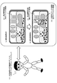
- FIG. 2 shows a state in which a user wearing a light-transmitting AR image display device 10 walks around the park and "points" toward the water surface of the pond while looking at the water surface of the pond near the pond. Is shown.
- the light transmission type AR image display device 10 has a camera, captures an image pointed by the user, and inputs the captured image to the three-dimensional map generation unit via the image analysis unit inside the device.
- the image analysis unit extracts feature points from the captured image, and the three-dimensional map generation unit generates a real-world three-dimensional map using the feature points extracted from the image.
- This three-dimensional map generation process is executed in real time by, for example, a SLAM (Simultaneus Localization and Mapping) process.
- SLAM Simultaneus Localization and Mapping
- SLAM Simultaneus Localization and Mapping
- the three-dimensional map generated by the three-dimensional map generation unit is input to the object identification unit of the image processing device.
- the object identification unit determines the real object area in the pointing direction of the user as the target area 11 by using the 3D map generated by the 3D map generation unit. Further, the object in the target area 11 is identified.
- the object identification unit applies, for example, semantic segmentation processing to perform real-world object identification processing.
- Semantic segmentation is a type of image recognition processing, and is a method of performing a task of recognizing an object in an image at the pixel level using deep learning. For example, based on the degree of agreement between the object identification dictionary data (learned data) in which shape information and other feature information of various actual objects are registered and the objects in the camera-captured image, for example, the constituent pixels of the image ( Pixel) A technique for identifying which object category each pixel belongs to. This semantic segmentation allows the identification of various objects contained in camera images, such as people, cars, buildings, roads, trees, ponds, lawns, and the like.
- the image analysis unit of the light transmission type AR image display device 10 determines that the object in the target area 11 in the pointing direction of the user is a "pond" based on the image captured by the camera.
- the content display control unit that executes the virtual object display control of the light-transmitting AR image display device 10 inputs the object identification result of the target area 11 and selects a virtual object (character or the like) to be displayed according to the object identification result. Determine and display the processing and display mode.
- control is performed to display an image of the “water fairy character” as the virtual object image 22.
- the virtual object image 22 is displayed as, for example, a 3D content image.
- FIG. 3 is a diagram illustrating an example of display control of different virtual objects executed by the image processing apparatus of the present disclosure. Similar to FIG. 2, the figure shown on the left side of FIG. 3 is also a view in which a user wearing the light-transmitting AR image display device 10 is walking around the park. The user is pointing in the direction of the lawn while looking at the lawn in the park.
- the object identification unit of the light transmission type AR image display device 10 outputs the analysis result that the object in the target area 11 in the pointing direction of the user is the "lawn” by analyzing the image captured by the camera.
- the content display control unit of the light-transmitting AR image display device 10 inputs the object identification result of the target area 11 and determines the selection process and display mode of the virtual object (character or the like) to be displayed according to the object identification result. To display.
- control is performed to display an image of the “meadow fairy character” as the virtual object image 23.
- FIG. 4 is a diagram illustrating an example of display control of different virtual objects executed by the image processing apparatus of the present disclosure. Similar to FIGS. 2 and 3, the figure shown on the left side of FIG. 4 is also a view in which a user wearing the light-transmitting AR image display device 10 is walking around the park. The user is pointing in the direction of the tree while looking at the tree in the park.
- the object identification unit of the light-transmitting AR image display device 10 outputs an analysis result that the object in the target area 11 in the pointing direction of the user is a "tree" by analyzing the image captured by the camera.
- the content display control unit of the light-transmitting AR image display device 10 inputs the object identification result of the target area 11 and determines the selection process and display mode of the virtual object (character or the like) to be displayed according to the object identification result. To display.
- control is performed to display an image of the “tree fairy character” as the virtual object image 23.
- the image processing apparatus of the present disclosure performs three-dimensional shape analysis of the real world using SLAM processing or the like, generates a three-dimensional map of the real world, and further performs object identification processing such as semantic segmentation to identify the real world.
- object identification processing such as semantic segmentation to identify the real world.
- the object in the target area in the three-dimensional map of is identified, and the display control of the virtual object such as a character to be displayed according to the identification result is executed.
- the target of the real object to be analyzed by the object identification process such as semantic segmentation can be limited to the area specified by the user's finger, that is, the target area. In this way, high-speed processing is realized by limiting the analysis range.
- the image processing apparatus of the present disclosure is not limited to the head-mounted display (HMD) type light-transmitting AR image display device 10 described with reference to FIG. 1, and is configured by an apparatus provided with various display units. can do.
- HMD head-mounted display
- the camera-photographed image display type AR image display device 30 shown in FIG. 5 may be used.
- the camera-photographed image display type AR image display device 30 shown in FIG. 5 has a non-transparent type display unit (display).
- the light-transmitting display unit is attached to the user so as to be set at a position in front of the user that can be observed by the user.
- the captured image of the camera 31 integrated in the camera-captured image display type AR image display device 30, that is, the camera-captured image 32 shown in FIG. 5 is displayed on the display unit in front of the user. That is, the image of the real object captured by the camera 31 is displayed on the display unit in front of the user, and the user can confirm the external scenery by looking at the image captured by the camera 32.
- a virtual object for example, a virtual object image 22 such as a character image is displayed on the display unit (display).
- the user can observe the camera-captured image 32 displayed on the display unit (display) of the camera-captured image display type AR image display device 30, that is, the real object image and the virtual object image 22 such as a character. , You can experience the feeling as if a virtual object such as a character exists in the real world.
- the image processing device of the present disclosure can be a portable display device such as a smartphone 40 as shown in FIG.
- the smartphone 40 shown in FIG. 6 has a display unit and a camera 41.
- the captured image of the camera 41 that is, the camera captured image 42 shown in the figure is displayed on the display unit. That is, the image of the real object captured by the camera 41 is displayed on the display unit, and the user can confirm the external scenery by looking at the image captured by the camera.
- a virtual object for example, a virtual object image such as a character image is displayed on the display unit (display).
- the user can observe the camera-photographed image displayed on the display unit (display) of the smartphone 40, that is, the real object image and the virtual object image such as a character, as if the virtual object such as a character is in the real world. You can experience the feeling as if it exists in a shape.
- the image analysis unit of the image processing device analyzes the touch position, and further, the actual object at the touch position is displayed. Determine the type.
- the content display control unit of the image processing device executes display control of a virtual object such as a character according to the determination result.
- the image processing device of the present disclosure identifies the real object in the target area, which is the display position of the virtual object, such as water, grass, or tree, and the identification result is obtained. Performs processing such as selecting and displaying a virtual object such as a character to be displayed according to.
- the image processing device of the present disclosure not only selects a display virtual object according to the identification result of the real object in the target area, but also changes the display mode of the virtual object such as a character according to the real object identification result. It also executes the process.
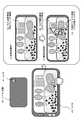
- FIG. 7 shows a display example of an AR image in which a virtual object (character) pops out from a pond, which is a real object, as an example of an AR image displayed on the display unit of the image processing device of the present disclosure.
- the content display control unit of the image processing device of the present disclosure performs a process of moving or moving a virtual object such as a character displayed in the target area according to a preset program.
- the example shown in FIG. 7 shows an example in which the character displayed in the target area 11 is displayed to be moved upward.
- FIG. 7 (1) At the moment -1 when the virtual object (character) pops out from the pond, only the upper half of the virtual object (character) is displayed on the water and the lower half is underwater.
- the content display control unit of the image processing device displays the virtual object image 50 on the water and the virtual object image 51 underwater in different display modes, as shown in FIG. 7 (1). That is, the virtual object image 50 on the water is displayed as a normal image with a clear outline, while the virtual object image 51 underwater is displayed as an image having three-dimensional distortion so as to exist in the water.
- the content voice control unit of the image processing device outputs the sound of water (such as fluttering) as a sound effect when the character moves on the water via the speaker.
- the moment -2 when the virtual object (character) pops out from the pond in FIG. 7 (2) is an AR image display example after FIG. 7 (1).
- the whole body of the virtual object (character) is displayed on the water.
- the virtual object image 50 on the water becomes an image of the entire character, and the content display control unit of the image processing device displays the entire character image as an image with a clear outline.
- FIG. 8 is a diagram illustrating another specific example of the process of changing the display mode of a virtual object such as a character according to the identification result of the real object.
- FIG. 8 shows a display example of an AR image displaying a shadow of a virtual object (character) as an example of the AR image displayed on the display unit of the image processing apparatus of the present disclosure. That is, when the content display control unit displays the character in the target area 11, the shadow of the character is also displayed.
- “(1) Character shadow display example when the shadowed surface is a flat surface” shown in FIG. 8 is This is an example of displaying the shadow when the surface on which the shadow of the virtual object (character) image 50 is reflected is a flat surface such as an indoor floor or an external sidewalk.
- the content display control unit of the image processing device virtuals the virtual object image 50, which is a three-dimensional character, when it is displayed in the target area 11.
- the virtual object shadow image 52 showing the shadow of the object image 50 is displayed as an image with a clear outline.
- FIG. 8 “(2) An example of displaying the shadow of a character when the surface on which the shadow is reflected is a non-planar surface (sandbox, etc.)”, This is an example of displaying a shadow when the surface on which the shadow of the virtual object (character) image 50 is reflected is not a flat surface such as a sandbox.
- the content display control unit of the image processing device sets the virtual object image 50, which is a three-dimensional character, in the target area 11.
- the virtual object shadow image 52 showing the shadow of the virtual object image 50 is displayed as a bumpy image with an unclear outline.
- the content display control unit of the image processing device of the present disclosure controls to change and display the display mode of the virtual object according to the identification result of the real object in the target area for displaying the virtual object.
- the content voice control unit controls the output of sound effects according to the identification result of the real object in the target area.
- the image processing apparatus of the present disclosure includes the light transmissive AR image display device 10 described with reference to FIG. 1, or the camera-captured image display type AR image display device 30 described with reference to FIG. Alternatively, it can be realized as a device having various forms such as a portable display device such as the smartphone 40 described with reference to FIG.
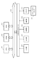
- FIG. 9 is a block diagram showing a configuration example of the image processing apparatus of the present disclosure that can take these various forms. The configuration of the image processing apparatus 100 shown in FIG. 9 will be described.
- the image processing device 100 includes a data input unit 110, a data processing unit 120, a data output unit 130, and a communication unit 140.
- the data input unit 110 includes an external shooting camera 111, an internal shooting camera 112, a motion sensor (gyro, acceleration sensor, etc.) 113, an operation unit 114, and a microphone 115.
- the data processing unit 120 includes an externally photographed image analysis unit 121, a three-dimensional map generation unit 122, an internally photographed image analysis unit 123, a device attitude analysis unit 124, a voice analysis unit 125, an object identification unit 126, a spatial map data 127, and class support. It has update time data 128.
- the data output unit 130 includes a content display control unit 131, a content audio control unit 132, a display unit 133, a speaker 134, and class-compatible virtual object data (3D model, audio data, etc.) 135.
- the external shooting camera 111 of the data input unit 110 shoots an external image.
- the outside scenery in the environment where the user wearing the HMD is present is photographed.
- a mobile terminal such as a smartphone
- it is a camera provided in the smartphone or the like.
- the internal photographing camera 112 basically has a configuration peculiar to the HMD, and captures an image of the area of the user's eyes for analyzing the direction of the user's line of sight.
- the motion sensor (gyro, acceleration sensor, etc.) 113 detects the posture and movement of the main body of the image processing device 100, such as an HMD or a smartphone.
- the motion sensor 113 is composed of, for example, a gyro, an acceleration sensor, a direction sensor, a positioning sensor, an inertial measurement unit (IMU), and the like.
- the operation unit 114 is an operation unit that can be operated by the user, and is used for inputting, for example, a target area or other processing instructions.
- the microphone 115 is used for inputting an instruction by voice input by the user. It can also be used to input external environmental sounds.
- the externally captured image analysis unit 121 inputs an externally captured image captured by the externally captured image 111, and extracts feature points from the externally captured image.
- This feature point extraction process is a feature point to be used for generating a three-dimensional map, and the extracted feature point information is stored in the three-dimensional map generation unit 122 together with an externally captured image captured by the external photographing camera 111. input.
- the three-dimensional map generation unit 122 generates a three-dimensional map composed of an external real object based on an externally photographed image photographed by the externally photographed camera 111 and feature points extracted by the externally photographed image analysis unit 121. To do.
- This three-dimensional map generation process is executed as a real-time process by, for example, a SLAM (Simultaneus Localization and Mapping) process.
- SLAM Simultaneus Localization and Mapping
- the SLAM (Simultaneus Localization and Mapping) process is a process that enables self-position estimation and environment three-dimensional map generation to be executed in parallel at the same time.
- the 3D map data of the external environment generated by the 3D map generation unit 122 is input to the object identification unit 126.
- the internal imaging image analysis unit 123 analyzes the user's line-of-sight direction based on the image of the user's eye region captured by the internal imaging camera 112.
- the internally photographed image analysis unit 123 also has a configuration peculiar to the HMD basically like the above-mentioned internal photographed camera 112.
- the user line-of-sight information analyzed by the internally captured image analysis unit 123 is input to the object identification unit 126.
- the device posture analysis unit 124 analyzes the posture and movement of the image processing device 100 main body such as an HMD or a smartphone based on the sensor detection information measured by the motion sensor (gyro, acceleration sensor, etc.) 113.
- the posture and motion information of the image processing device 100 main body analyzed by the device posture analysis unit 124 is input to the object identification unit 126.
- the voice analysis unit 125 analyzes the user voice and the environmental sound input from the microphone 115. The analysis result is input to the object identification unit 126.
- the object identification unit 126 inputs the three-dimensional map generated by the three-dimensional map generation unit 122, determines the target area to be set in the display area of the virtual object, and further identifies the real object in the determined target area. To execute. For example, the object identification process such that the target area is a pond or a tree is executed.
- the target area identification process can be executed by various methods. For example, it can be performed using the image of the user's finger included in the three-dimensional map. The intersection of the extension line in the pointing direction of the user and the real object on the three-dimensional map is obtained, and for example, a circular region having a predetermined radius centered on the intersection is determined as the target region.
- the target area can be specified by a method other than pointing by the user.
- the object identification unit 126 can use any of the following information as information to be used for determining the target area.
- the object identification unit 126 obtains an extension line in the line-of-sight direction of the user and an intersection of an actual object on the three-dimensional map. For example, a circular region having a predetermined radius centered on the intersection is determined as the target region.
- the object identification unit 126 is in the forward direction of the HMD worn by the user or the user's smartphone.
- the intersection of the extension line and the real object on the three-dimensional map is obtained, and for example, a circular region having a predetermined radius centered on the intersection is determined as the target region.
- the object identification unit 126 uses, for example, the target area based on the user operation information input via the input unit of the image processing device 100. To determine. For example, in the configuration using the smartphone shown in FIG. 6 described above, it is possible to input screen position designation information by the user's finger as user operation information and set this designated position as the center position of the target area. ..
- the operation unit 114 a rod-shaped instruction member separate from the image processing device 100 is used, the instruction direction information of the instruction member is input to the object identification unit 126, and the target area is determined based on the instruction direction. It may be configured to be used.
- the object identification unit 126 analyzes, for example, the utterance by the user to determine the target area. For example, when the user utterance is an utterance such as "the pond in front", the color is determined as the target area.
- the object identification unit 126 may perform target area determination processing other than these. For example, a three-dimensional map generated based on an image taken by an external camera 111 or a horizontal surface such as the ground, floor, or water surface is detected based on the detection information of the motion sensor 113, and the photographed image is captured. The process of determining the region of the horizontal plane closest to the central region as the target region may be performed.
- a user performs a virtual ball throwing operation, photographs the image with an external camera 111, analyzes the captured image, analyzes the landing point of the ball, and sets this landing point at the center position of the target area. You may perform processing such as setting.
- the object identification unit 126 uses any of the methods described above to determine the target area to be the virtual object display area. Further, the real object identification process of the determined target area is executed. For example, the object identification process such that the target area is a pond or a tree is executed.
- Semantic segmentation is an image based on the degree of matching between object identification dictionary data (learned data) that registers various actual object shape information and other feature information, and objects in, for example, camera-captured images. This is a technique for identifying which object category each of the constituent pixels (pixels) belongs to.
- This semantic segmentation allows the identification of various objects contained in camera images, such as people, cars, buildings, roads, trees, ponds, lawns, and the like.
- the real object identification process executed by the object identification unit 126 is executed only for the target area or only for a limited range of the surrounding area including the target area. By performing such a limited range of processing, high-speed processing, that is, real-time processing becomes possible.
- the real-time processing means that, for example, after the user specifies the target area, the real object identification processing is executed immediately. As a result, object identification is completed without time delay, for example, while the user is observing the target area.
- the identification result of the real object in the target area analyzed by the object identification unit 126 is input to the content display control unit 131 of the data output unit 130 and the content voice control unit 132.
- the content display control unit 131 of the data output unit 130 inputs the object identification result of the target area from the object identification unit 126, and determines the selection process and display mode of the virtual object (character or the like) to be displayed according to the object identification result. It is displayed on the display unit 133. Specifically, for example, the display processing of virtual objects (characters and the like) as shown in FIGS. 2 to 4, 7, and 8 described above is executed.
- the content voice control unit 132 of the data output unit 130 inputs the object identification result of the target area from the object identification unit 126, determines the voice to be output according to the object identification result, and outputs the sound via the speaker 134. Specifically, for example, as shown in FIG. 7 described above, when a virtual object appears from a pond which is a real object, a process of outputting the sound of water is executed.
- the content display control unit 131 of the data output unit 130 and the content audio control unit 132 acquire the 3D content of the disguised object and various audio data recorded in the class-compatible virtual object data 135 and execute data output. ..
- class-corresponding virtual object data 1335 3D contents of a disguise object for display and various audio data associated with the real object type (class) corresponding to the identification result of the real object in the target area are recorded.
- class-compatible virtual object data 135 A specific example of the class-compatible virtual object data 135 will be described later.
- the image processing device 100 captures a camera like the camera-captured image display type AR image display device 30 described with reference to FIG. 5 and the smartphone 40 described with reference to FIG. In the case of a configuration in which an image is displayed, a photographed image of the external photographing camera 11 is input, a display image in which a virtual object is superimposed on the photographed image is generated, and the display image is displayed on the display unit 133.
- the communication unit 140 communicates with, for example, an external server and acquires the 3D content of the character, which is virtual content.
- various data and parameters required for data processing may be acquired from an external server.
- the object identification unit 126 stores the identification result as spatial map data 127 in the storage unit when the real object in the target area is identified.
- FIG. 10 shows a data configuration example of the spatial map data 127.
- the spatial map data stores the corresponding data of the following data.
- A Time stamp (sec)
- B Location information
- c Class
- d Elapsed time after identification processing
- the time stamp (sec) is time information when the object identification process is executed.
- the position information is the position information of the real object that is the object identification target.
- Various methods can be used for recording the position information.
- the example shown in the figure is an example described as a mesh with a list of three-dimensional coordinates (x, y, z).
- the configuration may be such that the position information of the center position of the target area is recorded.
- the class is object type information as an object identification result.
- the elapsed time (sec) after the identification process is the elapsed time from the completion of the object identification process.
- the object identification unit 126 executes the identification process of the real object in the target area. After that, the object identification unit 126 repeatedly executes the object identification process for the area, and the spatial map shown in FIG. The data is updated sequentially.
- the update processing interval differs depending on the type (class) of the identified real object.
- the specified update time data that differs depending on the type (class) of the real object is registered in advance as class-corresponding update time data 128.
- FIG. 11 shows a data example of the class correspondence update time data 128.
- the class correspondence update time data 128 is data in which the following data are associated with each other.
- ID is an identifier of registered data.
- category is a category of the type (class) of the real object.
- class is the type information of the real object.
- update time (sec) is a time indicating the update interval of the real object identification process.
- the update time is 2 sec. Objects such as shadows change significantly over time, so the update time is set short.
- the object identification unit 126 refers to the data of the class correspondence update time data 128, and repeats and executes the object identification process at any time at a time interval specified for the identified object.
- the real objects detected by the new identification process are sequentially registered as the spatial map data 127 described with reference to FIG.
- the content display control unit 131 and the content audio control unit 132 of the data output unit 130 acquire the 3D content of the disguised object and various audio data recorded in the class-compatible virtual object data 135. Perform data output.
- class-corresponding virtual object data 1335 3D contents of a disguise object for display and various audio data associated with the real object type (class) corresponding to the identification result of the real object in the target area are recorded.
- class-compatible virtual object data 135 A specific example of the class-compatible virtual object data 135 will be described with reference to FIG.
- each of the following data is recorded in association with the class-corresponding virtual object data 135.
- (A) Class (b) Virtual object 3D model (character 3D model)
- the class is the type information of the real object.
- the virtual object 3D model (character 3D model) registers a 3D model of a virtual object (character) to be output (displayed) according to each class, that is, the type of the real object in the target area.
- the ID that can output 3D and the 3D model are recorded together, but for example, only the ID is recorded and the 3D model corresponding to the ID is acquired from another database based on the ID. May be.
- the class-compatible virtual object data 135 records the 3D contents of the disguise object for display and various audio data associated with the real object type (class) corresponding to the identification result of the real object in the target area. Has been done.
- the output mode information of each virtual object is also recorded in the class-compatible virtual object data 135.
- information such as display mode information when the real object in the target region is water and display mode information when the real object in the target area is a sandbox is also recorded.
- the content display control unit 131 of the data output unit 130 and the content voice control unit 132 are used to store 3D content of a fake object and various voice data recorded in the class-compatible virtual object data 135 storing the data as shown in FIG. Is acquired and data output is executed.
- the process according to the flowchart shown in FIG. 13 and below is a process mainly executed by the data processing unit 120 of the image processing apparatus 100.
- the data processing unit 120 includes a CPU having a program execution function, and executes processing according to a flow according to a program stored in the storage unit.
- the processing of each step of the flow shown in FIG. 13 will be described.
- Step S101 First, the data processing unit 120 of the image processing device 100 inputs the captured image of the external photographing camera in step S101.
- step S102 the data processing unit 120 extracts feature points from the input captured image of the external shooting camera.
- This process is a process executed by the externally captured image analysis unit 121 of the data processing unit 120 shown in FIG.
- the externally captured image analysis unit 121 extracts feature points from the input captured image of the externally captured camera.
- This feature point extraction process is a feature point to be used for generating a three-dimensional map, and the extracted feature point information is input to the three-dimensional map generation unit 122 together with an externally shot image taken by an external shooting camera. To do.
- step S103 the data processing unit generates a three-dimensional map by using the external captured image captured by the external photographing camera and the feature point information thereof.
- This process is a process executed by the three-dimensional map generation unit 122 of the data processing unit 120 shown in FIG.
- the three-dimensional map generation unit 122 generates a three-dimensional map composed of an external real object based on an externally photographed image photographed by the externally photographed camera 111 and feature points extracted by the externally photographed image analysis unit 121. To do.
- This three-dimensional map generation process is executed as a real-time process by, for example, a SLAM (Simultaneus Localization and Mapping) process.
- SLAM Simultaneus Localization and Mapping
- Step S104 Next, the data processing unit executes the target area determination process in step S104.
- This process is a process executed by the object identification unit 126 of the data processing unit 120 shown in FIG.
- the object identification unit 126 determines a target area to be used as a virtual object display area.
- various methods can be applied to the determination process of the target area. For example, it can be performed using the image of the user's finger included in the three-dimensional map. That is, the intersection of the extension line in the pointing direction of the user and the real object on the three-dimensional map is obtained, and for example, a circular region having a predetermined radius centered on the intersection is determined as the target region.
- the target area by using the input information from each component of the data input unit 110 shown in FIG. Specifically, it is the following input information.
- the target area may be determined using any of these input information.
- FIG. 14 (1) is a determination sequence of the target region based on the analysis of the pointing direction of the user.
- the target area determination process based on the analysis of the user's pointing direction is executed in the following process sequence.
- step S212 the intersection of the straight line consisting of the extension line in the pointing direction of the user and the real object is detected. This process is also executed by using the three-dimensional map generated by the three-dimensional map generation unit 122.
- a circular region centered on the intersection of the straight line formed by the extension line in the pointing direction of the user and the real object is determined as the target region.
- the shape of the target region is arbitrary, and may be a rectangular shape as well as a circular shape.
- the size of the target area is also arbitrary and can be set to various sizes. However, it is preferable that the shape and size are specified in advance and the target area is determined according to the specifications.
- FIG. 14 (2) is a determination sequence of the target region based on the user's line-of-sight direction analysis.
- the target area determination process based on the analysis of the user's line-of-sight direction is executed in the following process sequence.
- step S221 the line-of-sight direction of the user is analyzed.
- This analysis process is executed by the internal captured image analysis unit 123 based on the captured image of the internal captured image camera 112.
- step S222 the intersection of the straight line consisting of the extension line in the user's line-of-sight direction and the real object is detected. This process is executed by using the three-dimensional map generated by the three-dimensional map generation unit 122.
- step S223 a circular region centered on the intersection of the straight line formed by the extension line in the user's line-of-sight direction and the real object is determined as the target region.
- the shape and size of the target area can be set in various ways.
- FIG. 15 (3) is a determination sequence of the target area based on the analysis of the user's operation information.
- the target area determination process based on the analysis of user operation information is executed in the following process sequence.
- step S231 the user's operation information is analyzed. For example, there is a touch operation on the smartphone described above with reference to FIG.
- step S232 the actual object designated position based on the user operation information is detected.
- This process is executed, for example, as a process of detecting the contact position of the user's finger.
- step S233 a circular area centered on the actual object designated position based on the user operation information is determined as the target area.
- the shape and size of the target area can be set in various ways.
- FIG. 15 (4) is a determination sequence of the target region based on the analysis of the user's voice information.
- the target area determination process based on the analysis of the user's voice information is executed in the following processing sequence.
- step S241 the spoken voice of the user is analyzed.
- the user-spoken voice such as "front pond” is analyzed.
- step S242 the actual object designated position based on the user's voice information is detected.
- step S243 a circular region centered on the actual object designated position based on the user's utterance voice is determined as the target region.
- the shape and size of the target area can be set in various ways.
- Target area determination processing using the posture and motion information of the image processing device 100 main body analyzed by the device posture analysis unit 124.
- a three-dimensional map generated based on an image taken by the external camera 111 and a horizontal surface such as the ground, floor, and water surface are detected based on the detection information of the motion sensor 113, and the photographed image is executed. The process of determining the region of the horizontal plane closest to the central region of the camera as the target region.
- (C) The user performs an operation of throwing a virtual ball, photographs this with an external camera 111, analyzes the captured image, analyzes the landing point of the ball, and uses this landing point as the center position of the target area. The process to decide.
- (D) In addition, a process of analyzing at least one of user movement, user line of sight, user operation, user position, and user posture, and determining a target area based on the analysis result.
- the object identification unit 126 of the data processing unit 120 of the image processing device 100 executes the target area determination process in step S104.
- Step S105 the data processing unit identifies the real object in the target area in step S105. Specifically, the object identification process such as that the target area is a pond or a tree is executed.
- Semantic segmentation is an image based on the degree of matching between object identification dictionary data (learned data) that registers various actual object shape information and other feature information, and objects in, for example, camera-captured images. This is a technique for identifying which object category each of the constituent pixels (pixels) belongs to.
- the real object identification process executed by the object identification unit 126 is executed only for the target area or only for a limited range of the surrounding area including the target area. By performing such a limited range of processing, high-speed processing, that is, real-time processing becomes possible.
- the identification result of the real object in the target area analyzed by the object identification unit 126 is input to the content display control unit 131 of the data output unit 130 and the content voice control unit 132.
- Step S106 Next, in step S106, the type and output mode of the virtual object to be displayed in the target area are determined based on the real object (class) of the identified target area.
- This process is a process executed by the content display control unit 131 and the content audio control unit 132 of the data output unit 130 of the image processing device 100 shown in FIG.
- the content display control unit 131 of the data output unit 130 and the content voice control unit 132 refer to the class-compatible virtual object data 135 that records the data described above with reference to FIG. 12, and display the virtual object data 135 in the target area. Determine the object type and output mode.
- step S107 the virtual object is output (displayed) to the target area according to the type and output mode of the virtual object to be displayed in the target area determined in step S106.
- This process is also a process executed by the content display control unit 131 and the content audio control unit 132 of the data output unit 130 of the image processing device 100 shown in FIG.
- the content display control unit 131 inputs the object identification result of the target area from the object identification unit 126, determines the selection process and display mode of the virtual object (character, etc.) to be displayed according to the object identification result, and displays it on the display unit 133. To do. Specifically, for example, the display processing of virtual objects (characters and the like) as shown in FIGS. 2 to 4, 7, and 8 described above is executed.
- the content voice control unit 132 inputs the object identification result of the target area from the object identification unit 126, determines the voice to be output according to the object identification result, and outputs the voice through the speaker 134. Specifically, for example, as shown in FIG. 7 described above, when a virtual object appears from a pond which is a real object, a process of outputting the sound of water is executed.
- the flowchart shown in FIG. 16 is a flowchart illustrating a processing sequence of the image processing apparatus 100 that executes such processing. Hereinafter, the processing of each step of the flowchart shown in FIG. 16 will be described.
- steps S101 to S103 and steps S105 to S107 of the flowchart shown in FIG. 16 are the same as the processes of each step of the basic processing flow described above with reference to FIG. 16
- steps S301 to S303 of the flow shown in FIG. 16 and the process of step S104 are different from the flow shown in FIG. 13 described above. The processing of each step will be described.
- Step S301 is a process of inputting sensor detection information from the motion sensor 113 of the data input unit 110 of the image processing device 100 shown in FIG. 9 to the device attitude analysis unit 124 of the data processing unit 120.
- the motion sensor 113 has a gyro, an acceleration sensor, and the like, and is a sensor that detects the posture and movement of the image processing device 100 main body such as an HMD and a smartphone. Sensor detection information is input from the motion sensor 113 to the device posture analysis unit 124 of the data processing unit 120.
- Step S302 Next, in step S302, the direction of gravity is estimated based on the motion sensor detection information.
- This process is a process executed by the device posture analysis unit 124 of the data processing unit 120 shown in FIG.
- the device attitude analysis unit 124 of the data processing unit 120 calculates the direction of gravity using sensor detection information such as a gyro constituting the motion sensor 113 and an acceleration sensor.
- Step S303 Next, in step S303, the horizontal region region detection process is performed. This process is a process executed by the object identification unit 126 shown in FIG.
- the object identification unit 126 detects the horizontal plane region in the three-dimensional map by using the three-dimensional map generated by the three-dimensional map generation unit 122 and the gravity direction information input from the device attitude analysis unit 124. Specifically, for example, the ground or floor surface is detected.
- the horizontal plane region to be detected is not limited to a perfect horizontal plane, and may be a substantially horizontal region.
- a certain amount of unevenness or a slope having a certain degree of gradient is also determined to be a horizontal region and detected. It is possible to set in advance how much unevenness or inclination is allowed as the horizontal plane region.
- Step S104 the data processing unit executes the target area determination process in step S104.
- the target region is selected only from the horizontal plane region detected in step S303.
- This process is a process executed by the object identification unit 126 of the data processing unit 120 shown in FIG.
- the object identification unit 126 determines the target area to be the virtual object display area by limiting it to the horizontal plane area detected in step S303.
- various methods can be applied to the determination process of the target area. For example, it can be performed using the image of the user's finger included in the three-dimensional map. That is, the intersection of the extension line in the pointing direction of the user and the horizontal plane region that is a real object on the three-dimensional map and is determined to be a horizontal plane such as the ground or floor surface is obtained, and the intersection with this horizontal plane is set in advance. A circular area with a specified radius is determined as the target area.
- the configuration may use the following input information.
- the target area may be determined using any of these input information.
- steps S101 to S103 and the processing of steps S105 and subsequent steps are the same as the flowchart shown in FIG. 13 described above.
- the target area which is the output area of the virtual object that is a character
- a substantially horizontal surface such as on the ground or on the floor.
- the object identification unit 126 in the data processing unit 120 of the image processing apparatus 100 shown in FIG. 9 is set in the target area immediately after the target area is determined.
- the real object identification process is executed, but after that, the object identification process for the area is repeatedly executed, and the spatial map data shown in FIG. 10 is sequentially updated.
- the update processing interval differs depending on the type (class) of the identified real object.
- the specified update time data that differs depending on the type (class) of the real object is registered in advance as class-corresponding update time data 128.
- the class correspondence update time data 128 is data in which the following data are associated with each other as described above with reference to FIG. (A) ID (B) Category (c) Class (d) Update time (sec)
- ID is an identifier of registered data.
- category is a category of the type (class) of the real object.
- class is the type information of the real object.
- update time (sec) is a time indicating the update interval of the real object identification process.
- the update time is 2 sec. Objects such as shadows change significantly over time, so the update time is set short.
- the object identification unit 126 refers to the data of the class correspondence update time data 128, and repeats and executes the object identification process at any time at a time interval specified for the identified object.
- the real objects detected by the new identification process are sequentially registered as the spatial map data 127 described with reference to FIG.
- the flowchart shown in FIG. 17 is a flowchart illustrating a process including a repetitive execution sequence of the object identification process. Hereinafter, the processing of each step of the flowchart shown in FIG. 17 will be described.
- steps S101 to S105 and the processes of steps S106 to S107 of the flowchart shown in FIG. 17 are the same as the processes of each step of the basic processing flow described above with reference to FIG. 17
- steps S401 and S402 of the flow shown in FIG. 17 are different from the flow shown in FIG. 13 described above. The processing of each step will be described.
- Step S401 In steps S101 to S105, the process of step S401 is executed after the determination of the target area and the identification process of the real object (class) of the target area are executed.
- step S401 the object identification result of the target area executed in step S105 is recorded in the spatial map data.
- the spatial map data stores the corresponding data of the following data, as described above with reference to FIG.
- A Time stamp (sec)
- B Location information
- c Class
- d Elapsed time after identification processing
- the time stamp (sec) is time information when the object identification process is executed.
- the position information is the position information of the real object that is the object identification target.
- the class is object type information as an object identification result.
- the elapsed time (sec) after the identification process is the elapsed time from the completion of the object identification process.
- step S401 each of these data is registered in the spatial map data for the real object in the target area identified in step S105.
- Steps S106 to S107 The processes of steps S106 to S107 are the same as the processes described above with reference to FIG. That is, the following processing is executed.
- step S106 the type and output mode of the virtual object to be displayed in the target area are determined based on the real object (class) of the identified target area.
- step S107 the virtual object is output (displayed) to the target area according to the type and output mode of the virtual object to be displayed in the target area determined in step S106.
- Step S402 Further, after the processing of step S107, the elapsed time after the identification processing of the real object of the target area executed in step S105 in step S402 is defined in the class correspondence update time data described with reference to FIG. d) Determine whether or not the "update time" has been exceeded.
- step S101 If it is determined that the amount has been exceeded, the process returns to step S101, and the processes of step S101 and subsequent steps are repeated and executed. That is, the target area is determined and the real object identification process of the target area is executed again.
- the real object identification is executed again in the target area at the same position.
- the real object identification is executed in the target area at the new position.
- FIG. 18 is an example of the hardware configuration of the image processing apparatus 100 of the present disclosure described with reference to FIG. The hardware configuration shown in FIG. 18 will be described.
- the CPU (Central Processing Unit) 301 functions as a data processing unit that executes various processes according to a program stored in the ROM (Read Only Memory) 302 or the storage unit 308. For example, the process according to the sequence described in the above-described embodiment is executed.
- the RAM (Random Access Memory) 303 stores programs and data executed by the CPU 301. These CPU 301, ROM 302, and RAM 303 are connected to each other by a bus 304.
- the CPU 301 is connected to the input / output interface 305 via the bus 304, and the input / output interface 305 includes an input unit 306 including various sensors, a camera, a switch, a keyboard, a mouse, a microphone, and an output unit 307 including a display and a speaker. Is connected.
- the storage unit 308 connected to the input / output interface 305 is composed of, for example, a hard disk or the like, and stores programs executed by the CPU 301 and various data.
- the communication unit 309 functions as a transmission / reception unit for data communication via a network such as the Internet or a local area network, and further as a transmission / reception unit for broadcast waves, and communicates with an external device.
- the drive 310 connected to the input / output interface 305 drives a removable medium 311 such as a magnetic disk, an optical disk, a magneto-optical disk, or a semiconductor memory such as a memory card, and records or reads data.
- a removable medium 311 such as a magnetic disk, an optical disk, a magneto-optical disk, or a semiconductor memory such as a memory card
- An object identification unit that executes identification processing of real objects in the real world, It has a content display control unit that generates an AR (Augmented Reality) image in which a real object and a virtual object are superimposed and displayed.
- the object identification unit An object identification process for identifying a real object in the display area of the virtual object is executed.
- the content display control unit An image processing device that selects a virtual object to be displayed according to the object identification result identified by the object identification unit.
- the object identification unit is The image processing apparatus according to (1), which executes object identification processing by image recognition processing.
- the object identification unit is The image processing apparatus according to (2), which executes object identification processing by applying semantic segmentation processing.
- the object identification unit is The image processing apparatus according to any one of (1) to (3), wherein a target area to be displayed as a display area of the virtual object is determined, and a real object identification process of the determined target area is executed.
- the object identification unit is The image processing apparatus according to (4), wherein the target area is determined based on at least one of user movement, user line of sight, user operation, user position, and user posture.
- the object identification unit is The image processing apparatus according to (4) or (5), wherein the target region is selected from the horizontal plane region and determined.
- the content display control unit is The image processing apparatus according to (6), which displays the virtual object so as to be in contact with the horizontal plane region.
- the object identification unit is The image processing apparatus according to (1) to (7), which executes the object identification process as real-time processing.
- the object identification unit is The image processing apparatus according to any one of (1) to (8), which repeatedly executes object identification processing at predetermined time intervals according to the object type.
- the image processing apparatus is It has a 3D map generator that generates a 3D map of the real world based on images taken by a camera.
- the object identification unit The image processing apparatus according to any one of (1) to (9), wherein a target area to be a display area of the virtual object is determined by using the three-dimensional map.
- the three-dimensional map generation unit is The image processing apparatus according to (10), which generates a three-dimensional map of the real world by SLAM (Simultaneus Localization and Mapping) processing.
- SLAM Simultaneus Localization and Mapping
- the content display control unit is While selecting the virtual object to be displayed according to the object identification result identified in the object identification unit,
- the image processing apparatus according to any one of (1) to (11), which also controls the display mode of the virtual object to be displayed according to the object identification result.
- the image processing apparatus further includes It has a content audio control unit that executes audio output control.
- the content voice control unit The image processing apparatus according to any one of (1) to (12), wherein the sound to be output is determined and output according to the object identification result identified by the object identification unit.
- the object identification unit executes an object identification processing step that executes identification processing of a real object in the real world.
- the content display control unit executes a content display control step to generate an AR (Augmented Reality) image in which a real object and a virtual object are superimposed and displayed.
- the object identification processing step is It is a step of executing an object identification process for identifying a real object in the display area of the virtual object.
- the content display control step is An image processing method for executing a step of selecting a virtual object to be displayed according to an object identification result identified in the object identification processing step.
- a program that executes image processing in an image processing device Have the object identification unit execute the object identification processing step that executes the identification processing of the real object in the real world.
- the content display control unit is made to execute a content display control step for generating an AR (Augmented Reality) image in which a real object and a virtual object are superimposed and displayed.
- An object identification process for identifying a real object in the display area of the virtual object is executed, and the object identification process is executed.
- the series of processes described in the specification can be executed by hardware, software, or a composite configuration of both.
- executing processing by software install the program that records the processing sequence in the memory in the computer built in the dedicated hardware and execute it, or execute the program on a general-purpose computer that can execute various processing. It can be installed and run.
- the program can be pre-recorded on a recording medium.
- LAN Local Area Network
- the various processes described in the specification are not only executed in chronological order according to the description, but may also be executed in parallel or individually as required by the processing capacity of the device that executes the processes.
- the system is a logical set configuration of a plurality of devices, and the devices having each configuration are not limited to those in the same housing.
- a device and a method for selecting a virtual object to be displayed and changing a display mode according to the actual object type of the target area as the display area of the virtual object Is realized. Specifically, for example, it has an object identification unit that executes identification processing of a real object in the real world, and a content display control unit that generates an AR image in which a real object and a virtual object are superimposed and displayed. The object identification unit identifies the real object in the target area as the display area of the virtual object, and the content display control unit performs a process of selecting a virtual object to be displayed according to the object identification result and a process of changing the display mode.
- a device and a method for selecting a virtual object to be displayed and changing the display mode according to the actual object type of the target area as the display area of the virtual object are realized.
Abstract
Provided are a device and a method for selecting a virtual object to be displayed, in accordance with the real object type of a target region that is a region in which the virtual object is displayed, and changing a display mode. The device has an object identification unit for executing a process for identifying a real object in the real world, and a content display control unit for generating an augmented reality (AR) image in which the real object and the virtual object are displayed by being superimposed one on another. The object identification unit identifies the real object in the target region, which is the region in which the virtual object is displayed, and the content display control unit performs a process for selecting the virtual object to be displayed in accordance with the result of object identification and a process for changing the display mode.
Description
本開示は、画像処理装置、および画像処理方法、並びにプログラムに関する。さらに詳細には、現実に観察可能な実オブジェクトにキャラクタ画像等の仮想コンテンツを重畳して表示する拡張現実(AR:Augumented Reality)画像を生成して出力する画像処理装置、および画像処理方法、並びにプログラムに関する。
The present disclosure relates to an image processing apparatus, an image processing method, and a program. More specifically, an image processing device that generates and outputs an Augmented Reality (AR) image that superimposes and displays virtual contents such as character images on a real object that can be actually observed, an image processing method, and an image processing method. Regarding the program.
実空間で観察可能な実オブジェクトや、実オブジェクトと画像に仮想オブジェクトを重畳して表示した画像を拡張現実(AR:Augumented Reality)画像と呼ぶ。
A real object that can be observed in real space or an image that is displayed by superimposing a virtual object on a real object and an image is called an Augmented Reality (AR) image.
AR画像を利用したコンテンツやゲームで利用される仮想オブシェクトには様々な種類があるが、例えば人間と同じような動きをする仮想オブジェクト、すなわちキャラクタが利用されることが多い。
There are various types of virtual objects used in content and games that use AR images, but for example, virtual objects that behave like humans, that is, characters are often used.
AR画像は、例えばユーザの目に装着するヘッド・マウント・ディスプレイ(HMD)や、スマホ(スマートフォン)等の携帯端末等を利用して表示される。
ユーザは、AR画像を視聴することで、例えばAR画像中の表示キャラクタが実世界に存在するような感覚を楽しむことができる。 The AR image is displayed using, for example, a head-mounted display (HMD) worn by the user's eyes, a mobile terminal such as a smartphone (smartphone), or the like.
By viewing the AR image, the user can enjoy the feeling that the display character in the AR image exists in the real world, for example.
AR画像中にキャラクタを表示させる場合、例えばゲームプログラム等、コンテンツ再生プログラムに従った表示処理がなされる。
具体的には、プログラムに記録されているキャラクタ出力条件を満たす場合にプログラムに規定された手順でキャラクタが表示される。
しかし、このようなプログラムに規定されたキャラクタ表示を行うと、常に同じような処理が繰り返されることになり、面白みが薄れてしまう。 When displaying a character in an AR image, display processing is performed according to a content reproduction program such as a game program.
Specifically, when the character output condition recorded in the program is satisfied, the character is displayed according to the procedure specified in the program.
However, when the character display specified in such a program is performed, the same processing is always repeated, which makes it less interesting.
一方、近年、画像内のオブジェクトを識別する技術としてセマンティック・セグメンテーションについての研究や利用が進んでいる。セマンティック・セグメンテーションは、例えばカメラ撮影画像に含まれる様々なオブジェクト、例えば人、車、ビル、道路、木等、オブジェクトの種類を識別する技術である。
On the other hand, in recent years, research and use of semantic segmentation have been progressing as a technology for identifying objects in images. Semantic segmentation is a technique for identifying the types of various objects contained in a camera image, such as people, cars, buildings, roads, and trees.
なお、このセマンティック・セグメンテーションについて開示した文献として、例えば特許文献1(特開2015-207291号公報)がある。
As a document disclosed about this semantic segmentation, for example, Patent Document 1 (Japanese Unexamined Patent Publication No. 2015-207291) is available.
本開示は、実オブジェクトの種類に応じて表示するキャラクタの制御を行う画像処理装置、および画像処理方法、並びにプログラムを提供するものである。
The present disclosure provides an image processing device that controls a character to be displayed according to the type of a real object, an image processing method, and a program.
本開示の一実施例においては、上述したセマンティック・セグメンテーション等のオブジェクト識別処理によって画像の背景オブジェクトを識別し、識別結果に応じて表示するキャラクタを制御する画像処理装置、および画像処理方法、並びにプログラムを提供するものである。
In one embodiment of the present disclosure, an image processing device, an image processing method, and a program that identify a background object of an image by an object identification process such as the above-mentioned semantic segmentation and control a character to be displayed according to the identification result. Is to provide.
本開示の第1の側面は、
実世界上の実オブジェクトの識別処理を実行するオブジェクト識別部と、
実オブジェクトと仮想オブジェクトを重畳表示したAR(Augumented Reality)画像を生成するコンテンツ表示制御部を有し、
前記オブジェクト識別部は、
前記仮想オブジェクトの表示領域の実オブジェクトを識別するオブジェクト識別処理を実行し、
前記コンテンツ表示制御部は、
前記オブジェクト識別部において識別されたオブジェクト識別結果に応じて表示する仮想オブジェクトを選択する画像処理装置にある。 The first aspect of the disclosure is
An object identification unit that executes identification processing of real objects in the real world,
It has a content display control unit that generates an AR (Augmented Reality) image in which a real object and a virtual object are superimposed and displayed.
The object identification unit
An object identification process for identifying a real object in the display area of the virtual object is executed.
The content display control unit
It is in an image processing device that selects a virtual object to be displayed according to an object identification result identified by the object identification unit.
さらに、本開示の第2の側面は、
画像処理装置において実行する画像処理方法であり、
オブジェクト識別部が、実世界上の実オブジェクトの識別処理を実行するオブジェクト識別処理ステップを実行し、
コンテンツ表示制御部が、実オブジェクトと仮想オブジェクトを重畳表示したAR(Augumented Reality)画像を生成するコンテンツ表示制御ステップを実行し、
前記オブジェクト識別処理ステップは、
前記仮想オブジェクトの表示領域の実オブジェクトを識別するオブジェクト識別処理を実行するステップであり、
前記コンテンツ表示制御ステップは、
前記オブジェクト識別処理ステップにおいて識別されたオブジェクト識別結果に応じて表示する仮想オブジェクトを選択するステップを実行する画像処理方法にある。 Further, the second aspect of the present disclosure is
This is an image processing method executed in an image processing device.
The object identification unit executes an object identification processing step that executes identification processing of a real object in the real world.
The content display control unit executes a content display control step to generate an AR (Augmented Reality) image in which a real object and a virtual object are superimposed and displayed.
The object identification processing step is
It is a step of executing an object identification process for identifying a real object in the display area of the virtual object.
The content display control step is
The image processing method is to execute a step of selecting a virtual object to be displayed according to the object identification result identified in the object identification processing step.
さらに、本開示の第3の側面は、
画像処理装置において画像処理を実行させるプログラムであり、
オブジェクト識別部に、実世界上の実オブジェクトの識別処理を実行するオブジェクト識別処理ステップを実行させ、
コンテンツ表示制御部に、実オブジェクトと仮想オブジェクトを重畳表示したAR(Augumented Reality)画像を生成するコンテンツ表示制御ステップを実行させ、
前記オブジェクト識別処理ステップにおいては、
前記仮想オブジェクトの表示領域の実オブジェクトを識別するオブジェクト識別処理を実行させ、
前記コンテンツ表示制御ステップにおいては、
前記オブジェクト識別処理ステップにおいて識別されたオブジェクト識別結果に応じて表示する仮想オブジェクトを選択するステップを実行させるプログラムにある。 Further, the third aspect of the present disclosure is
A program that executes image processing in an image processing device.
Have the object identification unit execute the object identification processing step that executes the identification processing of the real object in the real world.
The content display control unit is made to execute a content display control step for generating an AR (Augmented Reality) image in which a real object and a virtual object are superimposed and displayed.
In the object identification processing step,
An object identification process for identifying a real object in the display area of the virtual object is executed, and the object identification process is executed.
In the content display control step,
There is a program that executes a step of selecting a virtual object to be displayed according to the object identification result identified in the object identification processing step.
なお、本開示のプログラムは、例えば、様々なプログラム・コードを実行可能な情報処理装置やコンピュータ・システムに対して、コンピュータ可読な形式で提供する記憶媒体、通信媒体によって提供可能なプログラムである。このようなプログラムをコンピュータ可読な形式で提供することにより、情報処理装置やコンピュータ・システム上でプログラムに応じた処理が実現される。
The program of the present disclosure is, for example, a program that can be provided by a storage medium or a communication medium that is provided in a computer-readable format to an information processing device or a computer system that can execute various program codes. By providing such a program in a computer-readable format, processing according to the program can be realized on an information processing apparatus or a computer system.
本開示のさらに他の目的、特徴や利点は、後述する本開示の実施例や添付する図面に基づくより詳細な説明によって明らかになるであろう。なお、本明細書においてシステムとは、複数の装置の論理的集合構成であり、各構成の装置が同一筐体内にあるものには限らない。
Still other objectives, features and advantages of the present disclosure will be clarified by more detailed description based on the examples of the present disclosure and the accompanying drawings described below. In the present specification, the system is a logical set configuration of a plurality of devices, and the devices having each configuration are not limited to those in the same housing.
本開示の一実施例の構成によれば、仮想オブジェクトの表示領域とするターゲット領域の実オブジェクト種類に応じて表示する仮想オブジェクトの選択や表示態様変更を行う装置、方法が実現される。
具体的には、例えば、実世界上の実オブジェクトの識別処理を実行するオブジェクト識別部と、実オブジェクトと仮想オブジェクトを重畳表示したAR画像を生成するコンテンツ表示制御部を有する。オブジェクト識別部は、仮想オブジェクトの表示領域とするターゲット領域の実オブジェクトを識別し、コンテンツ表示制御部は、オブジェクト識別結果に応じて表示する仮想オブジェクトを選択する処理や表示態様の変更処理を行う。
本構成により、仮想オブジェクトの表示領域とするターゲット領域の実オブジェクト種類に応じて表示する仮想オブジェクトの選択や表示態様変更を行う装置、方法が実現される。
なお、本明細書に記載された効果はあくまで例示であって限定されるものではなく、また付加的な効果があってもよい。 According to the configuration of one embodiment of the present disclosure, a device and a method for selecting a virtual object to be displayed and changing the display mode according to the actual object type of the target area as the display area of the virtual object are realized.
Specifically, for example, it has an object identification unit that executes identification processing of a real object in the real world, and a content display control unit that generates an AR image in which a real object and a virtual object are superimposed and displayed. The object identification unit identifies the real object in the target area as the display area of the virtual object, and the content display control unit performs a process of selecting a virtual object to be displayed according to the object identification result and a process of changing the display mode.
With this configuration, a device and a method for selecting a virtual object to be displayed and changing the display mode according to the actual object type of the target area as the display area of the virtual object are realized.
It should be noted that the effects described in the present specification are merely exemplary and not limited, and may have additional effects.
以下、図面を参照しながら本開示の画像処理装置、および画像処理方法、並びにプログラムの詳細について説明する。なお、説明は以下の項目に従って行なう。
1.本開示の画像処理装置の実行する処理の概要について
2.本開示の画像処理装置の構成例について
3.本開示の画像処理装置の実行する処理のシーケンスについて
3-(1)画像処理装置の実行する基本処理シーケンス
3-(2)ターゲット領域の設定領域をほぼ水平な面に設定する処理のシーケンス
3-(3)実オブジェクト識別処理の更新シーケンス
4.画像処理装置のハードウェア構成例について
5.本開示の構成のまとめ Hereinafter, the details of the image processing apparatus, the image processing method, and the program of the present disclosure will be described with reference to the drawings. The explanation will be given according to the following items.
1. 1. Outline of processing executed by the image processing apparatus of thepresent disclosure 2. Regarding the configuration example of the image processing apparatus of the present disclosure. Sequence of processing executed by the image processing apparatus of the present disclosure 3- (1) Basic processing sequence executed by the image processing apparatus 3- (2) Sequence of processing for setting the setting area of the target area to an almost horizontal surface 3- (3) Update sequence of real object identification processing 4. About the hardware configuration example of the image processing device 5. Summary of the structure of this disclosure
1.本開示の画像処理装置の実行する処理の概要について
2.本開示の画像処理装置の構成例について
3.本開示の画像処理装置の実行する処理のシーケンスについて
3-(1)画像処理装置の実行する基本処理シーケンス
3-(2)ターゲット領域の設定領域をほぼ水平な面に設定する処理のシーケンス
3-(3)実オブジェクト識別処理の更新シーケンス
4.画像処理装置のハードウェア構成例について
5.本開示の構成のまとめ Hereinafter, the details of the image processing apparatus, the image processing method, and the program of the present disclosure will be described with reference to the drawings. The explanation will be given according to the following items.
1. 1. Outline of processing executed by the image processing apparatus of the
[1.本開示の画像処理装置の実行する処理の概要について]
まず、図1以下を参照して、本開示の画像処理装置の実行する処理の概要について説明する。 [1. Outline of processing executed by the image processing apparatus of the present disclosure]
First, the outline of the processing executed by the image processing apparatus of the present disclosure will be described with reference to FIGS. 1 and the following.
図1には、本開示の画像処理装置の一例として、ヘッド・マウント・ディスプレイ(HMD)型の光透過型AR画像表示デバイス10を示している。
ユーザは、ユーザの目を覆うようにヘッド・マウント・ディスプレイ(HMD)型の光透過型AR画像表示デバイス10を装着する。 FIG. 1 shows a head-mounted display (HMD) type light-transmitting AR image display device 10 as an example of the image processing device of the present disclosure.
The user wears a head-mounted display (HMD) type light-transmitting AR image display device 10 so as to cover the user's eyes.
光透過型AR画像表示デバイス10は光透過型の表示部(ディスプレイ)を有する。光透過型の表示部(ディスプレイ)をユーザの目の前の位置に設定するようにユーザに装着される。
The light transmission type AR image display device 10 has a light transmission type display unit (display). It is attached to the user so as to set the light-transmitting display unit (display) at a position in front of the user.
ユーザは、光透過型AR画像表示デバイス10の光透過型の表示部(ディスプレイ)を介して外部の実オブジェクトをそのまま観察することができる。
さらに、光透過型の表示部(ディスプレイ)に、仮想オブジェクト、例えばキャラクタ画像等の仮想オブジェクト画像が表示される。 The user can observe the external real object as it is through the light transmission type display unit (display) of the light transmission type AR image display device 10.
Further, a virtual object, for example, a virtual object image such as a character image is displayed on the light transmission type display unit (display).
ユーザは、光透過型AR画像表示デバイス10を介して外部の実オブジェクトとキャラクタ等の仮想オブジェクト画像を併せて観察することが可能となり、あたかもキャラクタ等の仮想オブジェクトが実世界状に存在するかのような感覚を体感することができる。
The user can observe the external real object and the virtual object image such as a character together through the light transmission type AR image display device 10, and it is as if the virtual object such as a character exists in the real world. You can experience such a feeling.
図1の右側には、ユーザが、光透過型AR画像表示デバイス10を介して観察可能な画像の例を示している。
On the right side of FIG. 1, an example of an image that the user can observe through the light transmission type AR image display device 10 is shown.
(a)観察画像例1は、光透過型AR画像表示デバイス10を介して観察される外部の実オブジェクトからなる透過観察画像21によって構成されている。この画像例1には、仮想オブジェクトは表示されていない。
(A) Observation image example 1 is composed of a transmission observation image 21 composed of an external real object observed via a light transmission type AR image display device 10. The virtual object is not displayed in this image example 1.
一方、(b)観察画像例2は、光透過型AR画像表示デバイス10を介して観察される外部の実オブジェクトからなる透過観察画像21に併せて、キャラクタ画像等の仮想オブジェクト画像22を表示した画像例である。この画像例2は、ユーザが実オブジェクトと仮想オブジェクトを併せて観察可能な画像である。
On the other hand, in (b) observation image example 2, a virtual object image 22 such as a character image is displayed together with a transmission observation image 21 composed of an external real object observed via the light transmission type AR image display device 10. This is an image example. This image example 2 is an image in which the user can observe both the real object and the virtual object.
前述したように、実空間で観察可能な実オブジェクトや、実オブジェクトと画像に仮想オブジェクトを重畳して表示した画像を拡張現実(AR:Augumented Reality)画像と呼ぶ。
本開示の画像処理装置は、このAR画像の表示処理を行う装置である。 As described above, a real object that can be observed in the real space and an image that is displayed by superimposing a virtual object on the real object and the image are called an Augmented Reality (AR) image.
The image processing device of the present disclosure is a device that performs display processing of this AR image.
本開示の画像処理装置、例えば図1に示す光透過型AR画像表示デバイス10は、AR画像表示における仮想オブジェクトの表示制御を実行する。
The image processing device of the present disclosure, for example, the light transmission type AR image display device 10 shown in FIG. 1, executes display control of a virtual object in AR image display.
本開示の画像処理装置、例えば図1に示す光透過型AR画像表示デバイス10の実行する具体的な処理は、例えば以下の処理である。
(a)自己位置推定と環境3次元マップ生成を行うSLAM(Simultaneous Localization and Mapping)処理等を適用して、ユーザが光透過型AR画像表示デバイス10を介して観察している実世界の3次元マップを生成する処理。
(b)セマンティック・セグメンテーション等のオブジェクト識別処理によって実世界に含まれるオブジェクトを識別する処理。
(c)実世界のオブジェクト識別結果に応じて、表示する仮想オブジェクト(キャラクタ等)を選択し、また仮想オブジェクトの表示態様を制御する処理。
本開示の画像処理装置は、例えばこれらの処理を実行する。 The specific processing executed by the image processing apparatus of the present disclosure, for example, the light transmissive AR image display device 10 shown in FIG. 1, is, for example, the following processing.
(A) Real-world 3D that the user is observing through the light-transmitting AR image display device 10 by applying SLAM (Simultaneus Localization and Mapping) processing that performs self-position estimation and environment 3D map generation. The process of generating a map.
(B) A process for identifying an object included in the real world by an object identification process such as semantic segmentation.
(C) A process of selecting a virtual object (character or the like) to be displayed according to an object identification result in the real world and controlling a display mode of the virtual object.
The image processing apparatus of the present disclosure executes these processes, for example.
図2以下を参照して、本開示の画像処理装置が実行する仮想オブジェクトの表示制御例について説明する。
An example of display control of a virtual object executed by the image processing device of the present disclosure will be described with reference to FIG. 2 and the following.
図2の左に示す図は、光透過型AR画像表示デバイス10を装着したユーザが公園を歩き回り、池の近くで、池の水面を見ながら、池の水面方向に「指さし」を行った状態を示している。
The figure shown on the left of FIG. 2 shows a state in which a user wearing a light-transmitting AR image display device 10 walks around the park and "points" toward the water surface of the pond while looking at the water surface of the pond near the pond. Is shown.
光透過型AR画像表示デバイス10は、カメラを有しており、ユーザが指さしを行った画像を撮影し、撮影画像がデバイス内部の画像解析部を介して3次元マップ生成部に入力される。
画像解析部は撮影画像から特徴点を抽出し、3次元マップ生成部は、画像から抽出された特徴点を利用して実世界の3次元マップを生成する。
この3次元マップ生成処理は、例えば、SLAM(Simultaneous Localization and Mapping)処理によってリアルタイムで実行される。 The light transmission type AR image display device 10 has a camera, captures an image pointed by the user, and inputs the captured image to the three-dimensional map generation unit via the image analysis unit inside the device.
The image analysis unit extracts feature points from the captured image, and the three-dimensional map generation unit generates a real-world three-dimensional map using the feature points extracted from the image.
This three-dimensional map generation process is executed in real time by, for example, a SLAM (Simultaneus Localization and Mapping) process.
SLAM(Simultaneous Localization and Mapping)処理は、自己位置推定と環境3次元マップの生成を同時に並列して実行することを可能とした処理である。
SLAM (Simultaneus Localization and Mapping) processing is a processing that enables self-position estimation and environment three-dimensional map generation to be executed in parallel at the same time.
さらに、3次元マップ生成部が生成した3次元マップは、画像処理装置のオブジェクト識別部に入力される。
オブジェクト識別部は、3次元マップ生成部が生成した3次元マップを用いて、ユーザの指さし方向にある実オブジェクト領域をターゲット領域11として決定する。さらに、このターゲット領域11のオブジェクトを識別する。 Further, the three-dimensional map generated by the three-dimensional map generation unit is input to the object identification unit of the image processing device.
The object identification unit determines the real object area in the pointing direction of the user as the target area 11 by using the 3D map generated by the 3D map generation unit. Further, the object in the target area 11 is identified.
オブジェクト識別部は、例えば、セマンティック・セグメンテーション処理を適用して実世界のオブジェクトの識別処理を行う。
The object identification unit applies, for example, semantic segmentation processing to perform real-world object identification processing.
セマンティック・セグメンテーションは、画像認識処理の一種であり、ディープラーニングを用いて画像中の物体が画素レベルで何かを認識するタスクを行う手法である。例えば様々な実際のオブジェクトの形状情報やその他の特徴情報を登録したオブジェクト識別用の辞書データ(学習済みデータ)と、例えばカメラ撮影画像内のオブジェクトとの一致度に基づいて、画像の構成画素(ピクセル)各々が、どのオブジェクトカテゴリに属する画素であるかを識別する技術である。
このセマンティック・セグメンテーションにより、カメラ撮影画像に含まれる様々なオブジェクト、例えば人、車、ビル、道路、木、池、芝生等、オブジェクトの種類を識別することができる。 Semantic segmentation is a type of image recognition processing, and is a method of performing a task of recognizing an object in an image at the pixel level using deep learning. For example, based on the degree of agreement between the object identification dictionary data (learned data) in which shape information and other feature information of various actual objects are registered and the objects in the camera-captured image, for example, the constituent pixels of the image ( Pixel) A technique for identifying which object category each pixel belongs to.
This semantic segmentation allows the identification of various objects contained in camera images, such as people, cars, buildings, roads, trees, ponds, lawns, and the like.
図2に示す例では、光透過型AR画像表示デバイス10の画像解析部は、カメラ撮影画像に基づいて、ユーザの指さし方向のターゲット領域11のオブジェクトが「池」であると判定する。
In the example shown in FIG. 2, the image analysis unit of the light transmission type AR image display device 10 determines that the object in the target area 11 in the pointing direction of the user is a "pond" based on the image captured by the camera.
さらに、光透過型AR画像表示デバイス10の仮想オブジェクト表示制御を実行するコンテンツ表示制御部は、ターゲット領域11のオブジェクト識別結果を入力し、オブジェクト識別結果に従って表示すべき仮想オブジェクト(キャラクタ等)の選択処理や表示態様を決定して表示する。
Further, the content display control unit that executes the virtual object display control of the light-transmitting AR image display device 10 inputs the object identification result of the target area 11 and selects a virtual object (character or the like) to be displayed according to the object identification result. Determine and display the processing and display mode.
図2に示す例では、図2右側の(b)観察画像例2に示すように、仮想オブジェクト画像22として、「水の妖精キャラクタ」の画像を表示する制御を行う。
これは、ユーザの指さし方向の実オブジェクトが、「池」であるとの解析結果に基づく表示制御である。
すなわち、コンテンツ表示制御部は、ターゲット領域11のオブジェクト識別結果=「池」に応じた最適な仮想オブジェクトとして、「水の妖精キャラクタ」を選択して表示する処理を行う。
なお、仮想オブジェクト画像22は、例えば3Dコンテンツ画像として表示する。 In the example shown in FIG. 2, as shown in (b) Observation image example 2 on the right side of FIG. 2, control is performed to display an image of the “water fairy character” as the virtual object image 22.
This is display control based on the analysis result that the real object in the pointing direction of the user is a "pond".
That is, the content display control unit performs a process of selecting and displaying the "water fairy character" as the optimum virtual object according to the object identification result = "pond" of the target area 11.
The virtual object image 22 is displayed as, for example, a 3D content image.
図3は、本開示の画像処理装置が実行する異なる仮想オブジェクトの表示制御例を説明する図である。
図3の左に示す図も、図2と同様、光透過型AR画像表示デバイス10を装着したユーザが公園を歩き回っている図である。ユーザは、公園の芝生を見ながら、芝生方向に指さしを行っている。 FIG. 3 is a diagram illustrating an example of display control of different virtual objects executed by the image processing apparatus of the present disclosure.
Similar to FIG. 2, the figure shown on the left side of FIG. 3 is also a view in which a user wearing the light-transmitting AR image display device 10 is walking around the park. The user is pointing in the direction of the lawn while looking at the lawn in the park.
この場合、光透過型AR画像表示デバイス10のオブジェクト識別部は、カメラ撮影画像の解析により、ユーザの指さし方向であるターゲット領域11のオブジェクトが「芝生」であるとの解析結果を出力する。
In this case, the object identification unit of the light transmission type AR image display device 10 outputs the analysis result that the object in the target area 11 in the pointing direction of the user is the "lawn" by analyzing the image captured by the camera.
さらに、光透過型AR画像表示デバイス10のコンテンツ表示制御部は、ターゲット領域11のオブジェクト識別結果を入力し、オブジェクト識別結果に従って表示すべき仮想オブジェクト(キャラクタ等)の選択処理や表示態様を決定して表示する。
Further, the content display control unit of the light-transmitting AR image display device 10 inputs the object identification result of the target area 11 and determines the selection process and display mode of the virtual object (character or the like) to be displayed according to the object identification result. To display.
図3に示す例では、図3右側の(b)観察画像例2に示すように、仮想オブジェクト画像23として、「草原の妖精キャラクタ」の画像を表示する制御を行う。
これは、ユーザの指さし方向の実オブジェクトが、「芝生」であるとの解析結果に基づく表示制御である。
すなわち、コンテンツ表示制御部は、ターゲット領域11のオブジェクト識別結果=「芝生」に応じた最適な仮想オブジェクトとして、「芝生の妖精キャラクタ」を選択して表示する処理を行う。 In the example shown in FIG. 3, as shown in (b) Observation image example 2 on the right side of FIG. 3, control is performed to display an image of the “meadow fairy character” as the virtual object image 23.
This is display control based on the analysis result that the real object in the pointing direction of the user is a "lawn".
That is, the content display control unit performs a process of selecting and displaying the "lawn fairy character" as the optimum virtual object according to the object identification result = "lawn" of the target area 11.
図4は、本開示の画像処理装置が実行する異なる仮想オブジェクトの表示制御例を説明する図である。
図4の左に示す図も、図2、図3と同様、光透過型AR画像表示デバイス10を装着したユーザが公園を歩き回っている図である。ユーザは、公園の木を見ながら、木の方向に指さしを行っている。 FIG. 4 is a diagram illustrating an example of display control of different virtual objects executed by the image processing apparatus of the present disclosure.
Similar to FIGS. 2 and 3, the figure shown on the left side of FIG. 4 is also a view in which a user wearing the light-transmitting AR image display device 10 is walking around the park. The user is pointing in the direction of the tree while looking at the tree in the park.
この場合、光透過型AR画像表示デバイス10のオブジェクト識別部は、カメラ撮影画像の解析により、ユーザの指さし方向であるターゲット領域11のオブジェクトが「木」であるとの解析結果を出力する。
In this case, the object identification unit of the light-transmitting AR image display device 10 outputs an analysis result that the object in the target area 11 in the pointing direction of the user is a "tree" by analyzing the image captured by the camera.
さらに、光透過型AR画像表示デバイス10のコンテンツ表示制御部は、ターゲット領域11のオブジェクト識別結果を入力し、オブジェクト識別結果に従って表示すべき仮想オブジェクト(キャラクタ等)の選択処理や表示態様を決定して表示する。
Further, the content display control unit of the light-transmitting AR image display device 10 inputs the object identification result of the target area 11 and determines the selection process and display mode of the virtual object (character or the like) to be displayed according to the object identification result. To display.
図4に示す例では、図4右側の(b)観察画像例2に示すように、仮想オブジェクト画像23として、「木の妖精キャラクタ」の画像を表示する制御を行う。
これは、ユーザの指さし方向の実オブジェクトが、「木」であるとの解析結果に基づく表示制御である。
すなわち、コンテンツ表示制御部は、ターゲット領域11のオブジェクト識別結果=「木」に応じた最適な仮想オブジェクトとして、「木の妖精キャラクタ」を選択して表示する処理を行う。 In the example shown in FIG. 4, as shown in (b) Observation image example 2 on the right side of FIG. 4, control is performed to display an image of the “tree fairy character” as the virtual object image 23.
This is display control based on the analysis result that the real object in the pointing direction of the user is a "tree".
That is, the content display control unit performs a process of selecting and displaying the "tree fairy character" as the optimum virtual object according to the object identification result = "tree" of the target area 11.
このように、本開示の画像処理装置は、SLAM処理等を用いて実世界の3次元形状解析を行い、実世界の3次元マップを生成し、さらにセマンティック・セグメンテーション等のオブジェクト識別処理によって実世界の3次元マップ内のターゲット領域のオブジェクトを識別し、識別結果に応じて表示するキャラクタ等の仮想オブジェクトの表示制御を実行する。
As described above, the image processing apparatus of the present disclosure performs three-dimensional shape analysis of the real world using SLAM processing or the like, generates a three-dimensional map of the real world, and further performs object identification processing such as semantic segmentation to identify the real world. The object in the target area in the three-dimensional map of is identified, and the display control of the virtual object such as a character to be displayed according to the identification result is executed.
なお、セマンティック・セグメンテーション等のオブジェクト識別処理によって解析する実オブジェクトの対象は、例えば、ユーザの指によって指定された領域、すなわちターゲット領域のみに限定して処理を行うことが可能となる。このように、解析範囲を限定することにより高速処理が実現される。
Note that the target of the real object to be analyzed by the object identification process such as semantic segmentation can be limited to the area specified by the user's finger, that is, the target area. In this way, high-speed processing is realized by limiting the analysis range.
なお、本開示の画像処理装置は、図1を参照して説明したヘッド・マウント・ディスプレイ(HMD)型の光透過型AR画像表示デバイス10に限らず、様々な表示部を備えた装置によって構成することができる。
The image processing apparatus of the present disclosure is not limited to the head-mounted display (HMD) type light-transmitting AR image display device 10 described with reference to FIG. 1, and is configured by an apparatus provided with various display units. can do.
例えば、図5に示すカメラ撮影画像表示型AR画像表示デバイス30としてもよい。図5に示すカメラ撮影画像表示型AR画像表示デバイス30は、非透過型の表示部(ディスプレイ)を有する。光透過型の表示部(ディスプレイ)は、ユーザによって観察可能なユーザの目の前の位置に設定されるようにユーザに装着される。
For example, the camera-photographed image display type AR image display device 30 shown in FIG. 5 may be used. The camera-photographed image display type AR image display device 30 shown in FIG. 5 has a non-transparent type display unit (display). The light-transmitting display unit is attached to the user so as to be set at a position in front of the user that can be observed by the user.
カメラ撮影画像表示型AR画像表示デバイス30に一体化されたカメラ31の撮影画像、すなわち図5に示すカメラ撮影画像32がユーザの目の前の表示部に表示される。すなわちカメラ31が撮影する実オブジェクトの画像がユーザの目の前の表示部に表示され、ユーザは、カメラ撮影画像32を見ることで、外部の景色を確認することができる。
The captured image of the camera 31 integrated in the camera-captured image display type AR image display device 30, that is, the camera-captured image 32 shown in FIG. 5 is displayed on the display unit in front of the user. That is, the image of the real object captured by the camera 31 is displayed on the display unit in front of the user, and the user can confirm the external scenery by looking at the image captured by the camera 32.
さらに、表示部(ディスプレイ)には、仮想オブジェクト、例えばキャラクタ画像等の仮想オブジェクト画像22が表示される。
Further, a virtual object, for example, a virtual object image 22 such as a character image is displayed on the display unit (display).
ユーザは、カメラ撮影画像表示型AR画像表示デバイス30の表示部(ディスプレイ)に表示されるカメラ撮影画像32、すなわち実オブジェクト画像と、キャラクタ等の仮想オブジェクト画像22を併せて観察することが可能となり、あたかもキャラクタ等の仮想オブジェクトが実世界状に存在するかのような感覚を体感することができる。
The user can observe the camera-captured image 32 displayed on the display unit (display) of the camera-captured image display type AR image display device 30, that is, the real object image and the virtual object image 22 such as a character. , You can experience the feeling as if a virtual object such as a character exists in the real world.
さらに、本開示の画像処理装置は、図6に示すようなスマホ40等の携帯型表示装置とすることも可能である。
Further, the image processing device of the present disclosure can be a portable display device such as a smartphone 40 as shown in FIG.
図6に示すスマホ40は、表示部を有し、カメラ41を有する。カメラ41の撮影画像、すなわち図に示すカメラ撮影画像42が表示部に表示される。すなわちカメラ41が撮影する実オブジェクトの画像が表示部に表示され、ユーザは、カメラ撮影画像を見ることで、外部の景色を確認することができる。
The smartphone 40 shown in FIG. 6 has a display unit and a camera 41. The captured image of the camera 41, that is, the camera captured image 42 shown in the figure is displayed on the display unit. That is, the image of the real object captured by the camera 41 is displayed on the display unit, and the user can confirm the external scenery by looking at the image captured by the camera.
さらに、表示部(ディスプレイ)には、仮想オブジェクト、例えばキャラクタ画像等の仮想オブジェクト画像が表示される。
Further, a virtual object, for example, a virtual object image such as a character image is displayed on the display unit (display).
ユーザは、スマホ40の表示部(ディスプレイ)に表示されるカメラ撮影画像、すなわち実オブジェクト画像と、キャラクタ等の仮想オブジェクト画像を併せて観察することが可能となり、あたかもキャラクタ等の仮想オブジェクトが実世界状に存在するかのような感覚を体感することができる。
The user can observe the camera-photographed image displayed on the display unit (display) of the smartphone 40, that is, the real object image and the virtual object image such as a character, as if the virtual object such as a character is in the real world. You can experience the feeling as if it exists in a shape.
なお、このスマホ40の例では、ユーザがスマホ40の表示部のある位置をタッチした場合に、画像処理装置(スマホ)の画像解析部が、タッチ位置を解析し、さらにタッチ位置の実オブジェクトの種類を判別する。その後、画像処理装置(スマホ)のコンテンツ表示制御部が、この判別結果に応じてキャラクタ等の仮想オブジェクトの表示制御を実行する。
In the example of the smartphone 40, when the user touches a certain position of the display unit of the smartphone 40, the image analysis unit of the image processing device (smartphone) analyzes the touch position, and further, the actual object at the touch position is displayed. Determine the type. After that, the content display control unit of the image processing device (smartphone) executes display control of a virtual object such as a character according to the determination result.
上述したように、本開示の画像処理装置は、仮想オブジェクトの表示位置となるターゲット領域にある実オブジェクトが水であるか、草であるか、木であるか等のオブジェクト識別を行い、識別結果に応じて表示するキャラクタ等の仮想オブジェクトを選択して表示する処理等を行う。
As described above, the image processing device of the present disclosure identifies the real object in the target area, which is the display position of the virtual object, such as water, grass, or tree, and the identification result is obtained. Performs processing such as selecting and displaying a virtual object such as a character to be displayed according to.
さらに、本開示の画像処理装置は、ターゲット領域にある実オブジェクトの識別結果に応じた表示仮想オブジェクトの選択処理のみならず、実オブジェクト識別結果に応じてキャラクタ等の仮想オブジェクトの表示態様を変更する処理も実行する。
Further, the image processing device of the present disclosure not only selects a display virtual object according to the identification result of the real object in the target area, but also changes the display mode of the virtual object such as a character according to the real object identification result. It also executes the process.
図7以下を参照して、実オブジェクト識別結果に応じた仮想オブジェクトの表示態様の変更処理の具体例について説明する。
A specific example of the process of changing the display mode of the virtual object according to the real object identification result will be described with reference to FIG. 7 and the following.
図7には、本開示の画像処理装置の表示部に表示されるAR画像の一例として、実オブジェクトである池から仮想オブジェクト(キャラクタ)が飛び出すAR画像の表示例を示している。
FIG. 7 shows a display example of an AR image in which a virtual object (character) pops out from a pond, which is a real object, as an example of an AR image displayed on the display unit of the image processing device of the present disclosure.
本開示の画像処理装置のコンテンツ表示制御部は、ターゲット領域に表示したキャラクタ等の仮想オブジェクトを予め設定されたプログラムに従って移動させる処理や動かす処理を行う。
図7に示す例は、ターゲット領域11に表示したキャラクタを上方向に移動させる表示を行う例を示している。 The content display control unit of the image processing device of the present disclosure performs a process of moving or moving a virtual object such as a character displayed in the target area according to a preset program.
The example shown in FIG. 7 shows an example in which the character displayed in the target area 11 is displayed to be moved upward.
図7(1)池から仮想オブジェクト(キャラクタ)が飛び出す瞬間-1は、仮想オブジェクト(キャラクタ)の上半分のみが水上に表示され、下半分が水中にある状態である。
このような状態では、画像処理装置のコンテンツ表示制御部は、図7(1)に示すように、水上の仮想オブジェクト画像50と、水中の仮想オブジェクト画像51を異なる表示態様で表示する。
すなわち、水上の仮想オブジェクト画像50については、通常の輪郭がはっきりした画像として表示するが、水中の仮想オブジェクト画像51については、水中に存在するように3次元的な歪みを持つ画像として表示する。 FIG. 7 (1) At the moment -1 when the virtual object (character) pops out from the pond, only the upper half of the virtual object (character) is displayed on the water and the lower half is underwater.
In such a state, the content display control unit of the image processing device displays the virtual object image 50 on the water and the virtual object image 51 underwater in different display modes, as shown in FIG. 7 (1).
That is, the virtual object image 50 on the water is displayed as a normal image with a clear outline, while the virtual object image 51 underwater is displayed as an image having three-dimensional distortion so as to exist in the water.
さらに、画像処理装置のコンテンツ音声制御部は、キャラクタが水上に移動する際の効果音として、水の音(ピチャピチャ等)を、スピーカを介して出力する。
Furthermore, the content voice control unit of the image processing device outputs the sound of water (such as fluttering) as a sound effect when the character moves on the water via the speaker.
図7(2)池から仮想オブジェクト(キャラクタ)が飛び出す瞬間-2は、図7(1)の後のAR画像表示例である。この時点では、仮想オブジェクト(キャラクタ)の全身が水上に表示されている。この状態では、水上の仮想オブジェクト画像50がキャラクタ全体の画像となり、画像処理装置のコンテンツ表示制御部は、キャラクタ全体画像を輪郭がはっきりした画像として表示する。
The moment -2 when the virtual object (character) pops out from the pond in FIG. 7 (2) is an AR image display example after FIG. 7 (1). At this point, the whole body of the virtual object (character) is displayed on the water. In this state, the virtual object image 50 on the water becomes an image of the entire character, and the content display control unit of the image processing device displays the entire character image as an image with a clear outline.
図8は、実オブジェクトの識別結果に応じてキャラクタ等の仮想オブジェクト表示態様を変更する処理の別の具体例について説明する図である。
FIG. 8 is a diagram illustrating another specific example of the process of changing the display mode of a virtual object such as a character according to the identification result of the real object.
図8には、本開示の画像処理装置の表示部に表示されるAR画像の一例として、仮想オブジェクト(キャラクタ)の影を表示したAR画像の表示例を示している。
すなわち、コンテンツ表示制御部がターゲット領域11にキャラクタを表示する際、キャラクタの影の表示も併せて実行する。 FIG. 8 shows a display example of an AR image displaying a shadow of a virtual object (character) as an example of the AR image displayed on the display unit of the image processing apparatus of the present disclosure.
That is, when the content display control unit displays the character in the target area 11, the shadow of the character is also displayed.
図8に示す「(1)影の映る面が平面の場合のキャラクタの影の表示例」は、
仮想オブジェクト(キャラクタ)画像50の影の映る面が、室内の床や、外部の歩道等、平面である場合の影の表示例である。
このように仮想オブジェクト(キャラクタ)画像50の影の映る面が平面である場合、画像処理装置のコンテンツ表示制御部は、ターゲット領域11に3次元キャラクタである仮想オブジェクト画像50を表示する際、仮想オブジェクト画像50の影を示す仮想オブジェクト影画像52を輪郭がはっきりした画像として表示する。 “(1) Character shadow display example when the shadowed surface is a flat surface” shown in FIG. 8 is
This is an example of displaying the shadow when the surface on which the shadow of the virtual object (character) image 50 is reflected is a flat surface such as an indoor floor or an external sidewalk.
When the shadowed surface of the virtual object (character) image 50 is a flat surface in this way, the content display control unit of the image processing device virtuals the virtual object image 50, which is a three-dimensional character, when it is displayed in the target area 11. The virtual object shadow image 52 showing the shadow of the object image 50 is displayed as an image with a clear outline.
一方、図8「(2)影の映る面が非平面(砂場等)の場合のキャラクタの影の表示例は」、
仮想オブジェクト(キャラクタ)画像50の影の映る面が、例えば砂場等、平面でない場合の影の表示例である。
このように仮想オブジェクト(キャラクタ)画像50の影の映る面が砂場等、でこぼこのある面の場合、画像処理装置のコンテンツ表示制御部は、ターゲット領域11に3次元キャラクタである仮想オブジェクト画像50を表示する際、仮想オブジェクト画像50の影を示す仮想オブジェクト影画像52を輪郭がはっきりしない、でこぼこのある画像として表示する。 On the other hand, FIG. 8 “(2) An example of displaying the shadow of a character when the surface on which the shadow is reflected is a non-planar surface (sandbox, etc.)”,
This is an example of displaying a shadow when the surface on which the shadow of the virtual object (character) image 50 is reflected is not a flat surface such as a sandbox.
In this way, when the surface on which the shadow of the virtual object (character) image 50 is reflected is a rough surface such as a sandy field, the content display control unit of the image processing device sets the virtual object image 50, which is a three-dimensional character, in the target area 11. When displaying, the virtual object shadow image 52 showing the shadow of the virtual object image 50 is displayed as a bumpy image with an unclear outline.
このように、本開示の画像処理装置のコンテンツ表示制御部は、仮想オブジェクトを表示するターゲット領域の実オブジェクトの識別結果に応じて、仮想オブジェクトの表示態様も変更して表示する制御を行い、また、コンテンツ音声制御部はターゲット領域の実オブジェクトの識別結果に応じた効果音の出力制御を行う。
As described above, the content display control unit of the image processing device of the present disclosure controls to change and display the display mode of the virtual object according to the identification result of the real object in the target area for displaying the virtual object. , The content voice control unit controls the output of sound effects according to the identification result of the real object in the target area.
[2.本開示の画像処理装置の構成例について]
次に、本開示の画像処理装置の構成例について説明する。 [2. About the configuration example of the image processing apparatus of the present disclosure]
Next, a configuration example of the image processing apparatus of the present disclosure will be described.
次に、本開示の画像処理装置の構成例について説明する。 [2. About the configuration example of the image processing apparatus of the present disclosure]
Next, a configuration example of the image processing apparatus of the present disclosure will be described.
前述したように、本開示の画像処理装置は、図1を参照して説明した光透過型AR画像表示デバイス10、あるいは図5を参照して説明したカメラ撮影画像表示型AR画像表示デバイス30、あるいは図6を参照して説明したスマホ40等の携帯型の表示装置等、様々な形態を持つ装置として実現することができる。
As described above, the image processing apparatus of the present disclosure includes the light transmissive AR image display device 10 described with reference to FIG. 1, or the camera-captured image display type AR image display device 30 described with reference to FIG. Alternatively, it can be realized as a device having various forms such as a portable display device such as the smartphone 40 described with reference to FIG.
図9は、これら様々な形態を取り得る本開示の画像処理装置の一構成例を示すブロック図である。
図9に示す画像処理装置100の構成について説明する。 FIG. 9 is a block diagram showing a configuration example of the image processing apparatus of the present disclosure that can take these various forms.
The configuration of the image processing apparatus 100 shown in FIG. 9 will be described.
図9に示す画像処理装置100の構成について説明する。 FIG. 9 is a block diagram showing a configuration example of the image processing apparatus of the present disclosure that can take these various forms.
The configuration of the image processing apparatus 100 shown in FIG. 9 will be described.
図9に示すように、画像処理装置100は、データ入力部110、データ処理部120、データ出力部130、通信部140を有する。
As shown in FIG. 9, the image processing device 100 includes a data input unit 110, a data processing unit 120, a data output unit 130, and a communication unit 140.
データ入力部110は、外部撮影カメラ111、内部撮影カメラ112、モーションセンサ(ジャイロ、加速度センサ等)113、操作部114、マイク115を有する。
The data input unit 110 includes an external shooting camera 111, an internal shooting camera 112, a motion sensor (gyro, acceleration sensor, etc.) 113, an operation unit 114, and a microphone 115.
データ処理部120は、外部撮影画像解析部121、3次元マップ生成部122、内部撮影画像解析部123、デバイス姿勢解析部124、音声解析部125、オブジェクト識別部126、空間マップデータ127、クラス対応更新時間データ128を有する。
The data processing unit 120 includes an externally photographed image analysis unit 121, a three-dimensional map generation unit 122, an internally photographed image analysis unit 123, a device attitude analysis unit 124, a voice analysis unit 125, an object identification unit 126, a spatial map data 127, and class support. It has update time data 128.
データ出力部130は、コンテンツ表示制御部131、コンテンツ音声制御部132、表示部133、スピーカ134、クラス対応仮想オブジェクトデータ(3Dモデル、音声データ等)135を有する。
The data output unit 130 includes a content display control unit 131, a content audio control unit 132, a display unit 133, a speaker 134, and class-compatible virtual object data (3D model, audio data, etc.) 135.
データ入力部110の外部撮影カメラ111は、外部の画像を撮影する。例えば、HMDを装着したユーザのいる環境における外の景色等を撮影する。スマホ等の携帯端末の場合はスマホ等に備えられたカメラである。
内部撮影カメラ112は、基本的にHMD固有の構成であり、ユーザの視線方向を解析するためのユーザの目の領域の画像を撮影する。 Theexternal shooting camera 111 of the data input unit 110 shoots an external image. For example, the outside scenery in the environment where the user wearing the HMD is present is photographed. In the case of a mobile terminal such as a smartphone, it is a camera provided in the smartphone or the like.
The internal photographingcamera 112 basically has a configuration peculiar to the HMD, and captures an image of the area of the user's eyes for analyzing the direction of the user's line of sight.
内部撮影カメラ112は、基本的にHMD固有の構成であり、ユーザの視線方向を解析するためのユーザの目の領域の画像を撮影する。 The
The internal photographing
モーションセンサ(ジャイロ、加速度センサ等)113は、例えばHMDやスマホ等、画像処理装置100本体の姿勢や動きを検出する。
モーションセンサジ113は、例えば、ジャイロ、加速度センサ、方位センサ、一測位センサ、慣性計測装置(IMU)等によって構成される。 The motion sensor (gyro, acceleration sensor, etc.) 113 detects the posture and movement of the main body of the image processing device 100, such as an HMD or a smartphone.
Themotion sensor 113 is composed of, for example, a gyro, an acceleration sensor, a direction sensor, a positioning sensor, an inertial measurement unit (IMU), and the like.
モーションセンサジ113は、例えば、ジャイロ、加速度センサ、方位センサ、一測位センサ、慣性計測装置(IMU)等によって構成される。 The motion sensor (gyro, acceleration sensor, etc.) 113 detects the posture and movement of the main body of the image processing device 100, such as an HMD or a smartphone.
The
操作部114は、ユーザによって操作可能な操作部であり、例えばターゲット領域の入力や、その他の処理指示等の入力に利用される。
マイク115は、ユーザによる音声入力による指示の入力等に用いられる。また、外部の環境音の入力にも利用できる。 Theoperation unit 114 is an operation unit that can be operated by the user, and is used for inputting, for example, a target area or other processing instructions.
Themicrophone 115 is used for inputting an instruction by voice input by the user. It can also be used to input external environmental sounds.
マイク115は、ユーザによる音声入力による指示の入力等に用いられる。また、外部の環境音の入力にも利用できる。 The
The
次に、データ処理部120の構成部について説明する。
外部撮影画像解析部121は、外部撮影カメラ111によって撮影された外部の撮影画像を入力し、外部撮影画像から特徴点の抽出を行う。
この特徴点抽出処理は、3次元マップの生成に利用するための特徴点であり、抽出した特徴点情報は、外部撮影カメラ111によって撮影された外部の撮影画像とともに、3次元マップ生成部122に入力する。 Next, the constituent parts of thedata processing unit 120 will be described.
The externally captured image analysis unit 121 inputs an externally captured image captured by the externally capturedimage 111, and extracts feature points from the externally captured image.
This feature point extraction process is a feature point to be used for generating a three-dimensional map, and the extracted feature point information is stored in the three-dimensionalmap generation unit 122 together with an externally captured image captured by the external photographing camera 111. input.
外部撮影画像解析部121は、外部撮影カメラ111によって撮影された外部の撮影画像を入力し、外部撮影画像から特徴点の抽出を行う。
この特徴点抽出処理は、3次元マップの生成に利用するための特徴点であり、抽出した特徴点情報は、外部撮影カメラ111によって撮影された外部の撮影画像とともに、3次元マップ生成部122に入力する。 Next, the constituent parts of the
The externally captured image analysis unit 121 inputs an externally captured image captured by the externally captured
This feature point extraction process is a feature point to be used for generating a three-dimensional map, and the extracted feature point information is stored in the three-dimensional
3次元マップ生成部122は、外部撮影カメラ111によって撮影された外部の撮影画像と、外部撮影画像解析部121が抽出した特徴点に基づいて、外部の実オブジェクトによって構成される3次元マップを生成する。
The three-dimensional map generation unit 122 generates a three-dimensional map composed of an external real object based on an externally photographed image photographed by the externally photographed camera 111 and feature points extracted by the externally photographed image analysis unit 121. To do.
この3次元マップ生成処理は、例えば、SLAM(Simultaneous Localization and Mapping)処理によってリアルタイム処理として実行する。
前述したように、SLAM(Simultaneous Localization and Mapping)処理は、自己位置推定と環境3次元マップの生成を同時に並列して実行することを可能とした処理である。 This three-dimensional map generation process is executed as a real-time process by, for example, a SLAM (Simultaneus Localization and Mapping) process.
As described above, the SLAM (Simultaneus Localization and Mapping) process is a process that enables self-position estimation and environment three-dimensional map generation to be executed in parallel at the same time.
3次元マップ生成部122の生成した外部環境の3次元マップデータは、オブジェクト識別部126に入力される。
The 3D map data of the external environment generated by the 3D map generation unit 122 is input to the object identification unit 126.
内部撮影画像解析部123は、内部撮影カメラ112の撮影したユーザの目の領域の画像に基づいてユーザの視線方向を解析する。この内部撮影画像解析部123も、前述した内部撮影カメラ112と同様、基本的にHMD固有の構成である。
内部撮影画像解析部123の解析したユーザ視線情報は、オブジェクト識別部126に入力される。 The internal imagingimage analysis unit 123 analyzes the user's line-of-sight direction based on the image of the user's eye region captured by the internal imaging camera 112. The internally photographed image analysis unit 123 also has a configuration peculiar to the HMD basically like the above-mentioned internal photographed camera 112.
The user line-of-sight information analyzed by the internally capturedimage analysis unit 123 is input to the object identification unit 126.
内部撮影画像解析部123の解析したユーザ視線情報は、オブジェクト識別部126に入力される。 The internal imaging
The user line-of-sight information analyzed by the internally captured
デバイス姿勢解析部124は、モーションセンサ(ジャイロ、加速度センサ等)113によって計測されたセンサ検出情報に基づいて、HMDやスマホ等、画像処理装置100本体の姿勢や動きを解析する。
デバイス姿勢解析部124の解析した画像処理装置100本体の姿勢や動き情報は、オブジェクト識別部126に入力される。 The deviceposture analysis unit 124 analyzes the posture and movement of the image processing device 100 main body such as an HMD or a smartphone based on the sensor detection information measured by the motion sensor (gyro, acceleration sensor, etc.) 113.
The posture and motion information of the image processing device 100 main body analyzed by the deviceposture analysis unit 124 is input to the object identification unit 126.
デバイス姿勢解析部124の解析した画像処理装置100本体の姿勢や動き情報は、オブジェクト識別部126に入力される。 The device
The posture and motion information of the image processing device 100 main body analyzed by the device
音声解析部125は、マイク115から入力するユーザ音声や環境音の解析を行う。解析結果は、オブジェクト識別部126に入力される。
The voice analysis unit 125 analyzes the user voice and the environmental sound input from the microphone 115. The analysis result is input to the object identification unit 126.
オブジェクト識別部126は、3次元マップ生成部122が生成した3次元マップを入力し、仮想オブジェクトの表示領域に設定するためのターゲット領域を決定し、さらに、決定したターゲット領域の実オブジェクトの識別処理を実行する。例えばターゲット領域が池である、木である等のオブジェクト識別処理を実行する。
The object identification unit 126 inputs the three-dimensional map generated by the three-dimensional map generation unit 122, determines the target area to be set in the display area of the virtual object, and further identifies the real object in the determined target area. To execute. For example, the object identification process such that the target area is a pond or a tree is executed.
ターゲット領域の特定処理は、様々な方法によって実行可能である。
例えば、3次元マップに含まれるユーザの指の画像を用いて行うことが可能である。
ユーザの指さし方向の延長線と、3次元マップ上の実オブジェクトとの交点を求め、例えば、交点を中心とするあらかじめ規定した半径の円形領域をターゲット領域として決定する。 The target area identification process can be executed by various methods.
For example, it can be performed using the image of the user's finger included in the three-dimensional map.
The intersection of the extension line in the pointing direction of the user and the real object on the three-dimensional map is obtained, and for example, a circular region having a predetermined radius centered on the intersection is determined as the target region.
なお、ターゲット領域の指定は、ユーザによる指さし以外の方法で行うことも可能である。オブジェクト識別部126は、ターゲット領域の決定に使用するための情報として、以下のいずれかの情報を利用することができる。
(a)内部撮影画像解析部123の解析したユーザ視線情報
(b)デバイス姿勢解析部124の解析した画像処理装置100本体の姿勢や動き情報
(c)操作部114を介して入力するユーザ操作情報
(d)音声解析部125が解析したユーザ音声情報 The target area can be specified by a method other than pointing by the user. Theobject identification unit 126 can use any of the following information as information to be used for determining the target area.
(A) User line-of-sight information analyzed by the internally captured image analysis unit 123 (b) Postural and motion information of the image processing device 100 main body analyzed by the device posture analysis unit 124 (c) User operation information input via the operation unit 114 (D) User voice information analyzed by thevoice analysis unit 125
(a)内部撮影画像解析部123の解析したユーザ視線情報
(b)デバイス姿勢解析部124の解析した画像処理装置100本体の姿勢や動き情報
(c)操作部114を介して入力するユーザ操作情報
(d)音声解析部125が解析したユーザ音声情報 The target area can be specified by a method other than pointing by the user. The
(A) User line-of-sight information analyzed by the internally captured image analysis unit 123 (b) Postural and motion information of the image processing device 100 main body analyzed by the device posture analysis unit 124 (c) User operation information input via the operation unit 114 (D) User voice information analyzed by the
「(a)内部撮影画像解析部123の解析したユーザ視線情報」を利用する場合、オブジェクト識別部126は、ユーザの視線方向の延長線と、3次元マップ上の実オブジェクトとの交点を求め、例えば、交点を中心とする所定半径の円形領域をターゲット領域として決定する。
When "(a) user line-of-sight information analyzed by the internally captured image analysis unit 123" is used, the object identification unit 126 obtains an extension line in the line-of-sight direction of the user and an intersection of an actual object on the three-dimensional map. For example, a circular region having a predetermined radius centered on the intersection is determined as the target region.
「(b)デバイス姿勢解析部124の解析した画像処理装置100本体の姿勢や動き情報」を利用する場合、オブジェクト識別部126は、ユーザによって装着されたHMD、あるいはユーザの持つスマホの前方方向の延長線と、3次元マップ上の実オブジェクトとの交点を求め、例えば、交点を中心とする所定半径の円形領域をターゲット領域として決定する。
When "(b) posture and motion information of the image processing device 100 main body analyzed by the device posture analysis unit 124" is used, the object identification unit 126 is in the forward direction of the HMD worn by the user or the user's smartphone. The intersection of the extension line and the real object on the three-dimensional map is obtained, and for example, a circular region having a predetermined radius centered on the intersection is determined as the target region.
「(c)操作部114を介して入力するユーザ操作情報」を利用する場合、オブジェクト識別部126は、例えば画像処理装置100の入力部を介して入力されたユーザの操作情報に基づいてターゲット領域を決定する。
例えば、先に説明した図6に示すスマホを利用した構成において、ユーザの指による画面位置指定情報をユーザ操作情報として入力し、この指定位置をターゲッ領域の中心位置とするといった処理が可能である。 When "(c) user operation information input via theoperation unit 114" is used, the object identification unit 126 uses, for example, the target area based on the user operation information input via the input unit of the image processing device 100. To determine.
For example, in the configuration using the smartphone shown in FIG. 6 described above, it is possible to input screen position designation information by the user's finger as user operation information and set this designated position as the center position of the target area. ..
例えば、先に説明した図6に示すスマホを利用した構成において、ユーザの指による画面位置指定情報をユーザ操作情報として入力し、この指定位置をターゲッ領域の中心位置とするといった処理が可能である。 When "(c) user operation information input via the
For example, in the configuration using the smartphone shown in FIG. 6 described above, it is possible to input screen position designation information by the user's finger as user operation information and set this designated position as the center position of the target area. ..
なお、この他、操作部114として、画像処理装置100と別体の棒状の指示部材を用い、この指示部材の指示方向情報をオブジェクト識別部126に入力し、指示方向に基づいてターゲット領域を決定する構成としてもよい。
In addition, as the operation unit 114, a rod-shaped instruction member separate from the image processing device 100 is used, the instruction direction information of the instruction member is input to the object identification unit 126, and the target area is determined based on the instruction direction. It may be configured to be used.
「(d)音声解析部125が解析したユーザ音声情報」を利用する場合、オブジェクト識別部126は、例えばユーザによる発話を解析してターゲット領域を決定する。
例えば、ユーザ発話が「前の池」といった発話である場合、その色をターゲット領域として決定する。 When "(d) user voice information analyzed by thevoice analysis unit 125" is used, the object identification unit 126 analyzes, for example, the utterance by the user to determine the target area.
For example, when the user utterance is an utterance such as "the pond in front", the color is determined as the target area.
例えば、ユーザ発話が「前の池」といった発話である場合、その色をターゲット領域として決定する。 When "(d) user voice information analyzed by the
For example, when the user utterance is an utterance such as "the pond in front", the color is determined as the target area.
さらに、オブジェクト識別部126は、これら以外のターゲット領域決定処理を行ってもよい。例えば、外部撮影カメラ111によって撮影された画像に基づいて生成される3次元マップや、モーションセンサ113の検出情報に基づいて地面、床面、水面等の水平面の検出処理を実行し、撮影画像の中心領域に最も近い水平面の領域をターゲット領域として決定する処理を行ってもよい。
Further, the object identification unit 126 may perform target area determination processing other than these. For example, a three-dimensional map generated based on an image taken by an external camera 111 or a horizontal surface such as the ground, floor, or water surface is detected based on the detection information of the motion sensor 113, and the photographed image is captured. The process of determining the region of the horizontal plane closest to the central region as the target region may be performed.
また、例えばユーザが仮想的なボールを投げる動作を行い、これを外部撮影カメラ111によって撮影し、撮影画像を解析してボールの着地点を解析して、この着地点をターゲット領域の中心位置に設定するといった処理を行ってもよい。
Further, for example, a user performs a virtual ball throwing operation, photographs the image with an external camera 111, analyzes the captured image, analyzes the landing point of the ball, and sets this landing point at the center position of the target area. You may perform processing such as setting.
オブジェクト識別部126は、上述した方法のいずれかを用いて、仮想オブジェクト表示領域とするターゲット領域を決定する。さらに、決定したターゲット領域の実オブジェクトの識別処理を実行する。例えばターゲット領域が池である、木である等のオブジェクト識別処理を実行する。
The object identification unit 126 uses any of the methods described above to determine the target area to be the virtual object display area. Further, the real object identification process of the determined target area is executed. For example, the object identification process such that the target area is a pond or a tree is executed.
前述したように、この実オブジェクトのオブジェクト識別処理は、例えば、セマンティック・セグメンテーション処理を適用して実行する。
セマンティック・セグメンテーションは、様々な実際のオブジェクトの形状情報やその他の特徴情報を登録したオブジェクト識別用の辞書データ(学習済みデータ)と、例えばカメラ撮影画像内のオブジェクトとの一致度に基づいて、画像の構成画素(ピクセル)各々が、どのオブジェクトカテゴリに属する画素であるかを識別する技術である。
このセマンティック・セグメンテーションにより、カメラ撮影画像に含まれる様々なオブジェクト、例えば人、車、ビル、道路、木、池、芝生等、オブジェクトの種類を識別することができる。 As described above, the object identification process of this real object is executed by applying, for example, a semantic segmentation process.
Semantic segmentation is an image based on the degree of matching between object identification dictionary data (learned data) that registers various actual object shape information and other feature information, and objects in, for example, camera-captured images. This is a technique for identifying which object category each of the constituent pixels (pixels) belongs to.
This semantic segmentation allows the identification of various objects contained in camera images, such as people, cars, buildings, roads, trees, ponds, lawns, and the like.
なお、オブジェクト識別部126において実行する実オブジェクトの識別処理は、ターゲット領域のみ、あるいはターゲット領域を含む周囲領域の限られた範囲のみを対象として実行する。このような限定範囲の処理を行うことで高速の処理、すなわちリアルタイム処理が可能となる。なお。リアルタイム処理とは、例えばユーザによるターゲット領域の指定後、即座に実オブジェクトの識別処理が実行されることを意味する。これにより、例えばユーザがターゲット領域を観察している間に時間遅れなくオブジェクト識別が完了する。
Note that the real object identification process executed by the object identification unit 126 is executed only for the target area or only for a limited range of the surrounding area including the target area. By performing such a limited range of processing, high-speed processing, that is, real-time processing becomes possible. In addition. The real-time processing means that, for example, after the user specifies the target area, the real object identification processing is executed immediately. As a result, object identification is completed without time delay, for example, while the user is observing the target area.
オブジェクト識別部126が解析したターゲット領域の実オブジェクトの識別結果は、データ出力部130のコンテンツ表示制御部131と、コンテンツ音声制御部132に入力される。
The identification result of the real object in the target area analyzed by the object identification unit 126 is input to the content display control unit 131 of the data output unit 130 and the content voice control unit 132.
データ出力部130のコンテンツ表示制御部131は、オブジェクト識別部126からターゲット領域のオブジェクト識別結果を入力し、オブジェクト識別結果に従って表示すべき仮想オブジェクト(キャラクタ等)の選択処理や表示態様を決定して表示部133に表示する。
具体的には、例えば先に説明した図2~図4、図7、図8に示すような仮想オブジェクト(キャラクタ等)の表示処理を実行する。 The contentdisplay control unit 131 of the data output unit 130 inputs the object identification result of the target area from the object identification unit 126, and determines the selection process and display mode of the virtual object (character or the like) to be displayed according to the object identification result. It is displayed on the display unit 133.
Specifically, for example, the display processing of virtual objects (characters and the like) as shown in FIGS. 2 to 4, 7, and 8 described above is executed.
具体的には、例えば先に説明した図2~図4、図7、図8に示すような仮想オブジェクト(キャラクタ等)の表示処理を実行する。 The content
Specifically, for example, the display processing of virtual objects (characters and the like) as shown in FIGS. 2 to 4, 7, and 8 described above is executed.
データ出力部130のコンテンツ音声制御部132は、オブジェクト識別部126からターゲット領域のオブジェクト識別結果を入力し、オブジェクト識別結果に従って出力すべき音声を決定してスピーカ134を介して出力する。
具体的には、例えば先に説明した図7に示すように、実オブジェクトである池から仮想オブジェクトが現れる場合、水の音を出力する処理を実行する。 The contentvoice control unit 132 of the data output unit 130 inputs the object identification result of the target area from the object identification unit 126, determines the voice to be output according to the object identification result, and outputs the sound via the speaker 134.
Specifically, for example, as shown in FIG. 7 described above, when a virtual object appears from a pond which is a real object, a process of outputting the sound of water is executed.
具体的には、例えば先に説明した図7に示すように、実オブジェクトである池から仮想オブジェクトが現れる場合、水の音を出力する処理を実行する。 The content
Specifically, for example, as shown in FIG. 7 described above, when a virtual object appears from a pond which is a real object, a process of outputting the sound of water is executed.
なお、データ出力部130のコンテンツ表示制御部131と、コンテンツ音声制御部132は、クラス対応仮想オブジェクトデータ135に記録された仮装オブジェクトの3Dコンテンツや様々な音声データを取得してデータ出力を実行する。
The content display control unit 131 of the data output unit 130 and the content audio control unit 132 acquire the 3D content of the disguised object and various audio data recorded in the class-compatible virtual object data 135 and execute data output. ..
クラス対応仮想オブジェクトデータ135には、ターゲット領域の実オブジェクトの識別結果に相当する実オブジェクト種類(クラス)に対応づけられた表示用の仮装オブジェクトの3Dコンテンツや様々な音声データが記録されている。
クラス対応仮想オブジェクトデータ135の具体例については後述する。 In the class-correspondingvirtual object data 135, 3D contents of a disguise object for display and various audio data associated with the real object type (class) corresponding to the identification result of the real object in the target area are recorded.
A specific example of the class-compatiblevirtual object data 135 will be described later.
クラス対応仮想オブジェクトデータ135の具体例については後述する。 In the class-corresponding
A specific example of the class-compatible
また、コンテンツ表示部131は、画像処理装置100が、例えば図5を参照して説明したカメラ撮影画像表示型AR画像表示デバイス30や、図6を参照して説明したスマホ40のようにカメラ撮影画像を表示する処理を行う構成の場合は、外部撮影カメラ11の撮影画像を入力して、この撮影画像に仮想オブジェクトを重畳させた表示画像を生成して表示部133に表示する。
Further, in the content display unit 131, the image processing device 100 captures a camera like the camera-captured image display type AR image display device 30 described with reference to FIG. 5 and the smartphone 40 described with reference to FIG. In the case of a configuration in which an image is displayed, a photographed image of the external photographing camera 11 is input, a display image in which a virtual object is superimposed on the photographed image is generated, and the display image is displayed on the display unit 133.
通信部140は、例えば外部サーバと通信し、仮想コンテンツであるキャラクタの3Dコンテンツを取得する。その他、データ処理に必要となる様々なデータやパラメータを外部サーバから取得する構成としてもよい。
The communication unit 140 communicates with, for example, an external server and acquires the 3D content of the character, which is virtual content. In addition, various data and parameters required for data processing may be acquired from an external server.
なお、オブジェクト識別部126は、ターゲット領域の実オブジェクトの識別処理を行う際、識別結果を空間マップデータ127として記憶部に格納する。
図10に、空間マップデータ127のデータ構成例を示す。 Theobject identification unit 126 stores the identification result as spatial map data 127 in the storage unit when the real object in the target area is identified.
FIG. 10 shows a data configuration example of thespatial map data 127.
図10に、空間マップデータ127のデータ構成例を示す。 The
FIG. 10 shows a data configuration example of the
図10に示すように、空間マップデータは以下の各データの対応データが格納される。
(a)タイムスタンプ(sec)
(b)位置情報
(c)クラス
(d)識別処理後経過時間(sec) As shown in FIG. 10, the spatial map data stores the corresponding data of the following data.
(A) Time stamp (sec)
(B) Location information (c) Class (d) Elapsed time after identification processing (sec)
(a)タイムスタンプ(sec)
(b)位置情報
(c)クラス
(d)識別処理後経過時間(sec) As shown in FIG. 10, the spatial map data stores the corresponding data of the following data.
(A) Time stamp (sec)
(B) Location information (c) Class (d) Elapsed time after identification processing (sec)
(a)タイムスタンプ(sec)は、オブジェクト識別処理を実行した時間情報である。
(b)位置情報は、オブジェクト識別対象となった実オブジェクトの位置情報である。位置情報の記録方式は、様々な方式が利用可能である。図に示す例は、3次元座標(x,y,z)のリストによるメッシュとして記述した例である。この他、例えば、ターゲット領域の中心位置の位置情報を記録するといった構成とでもよい。 (A) The time stamp (sec) is time information when the object identification process is executed.
(B) The position information is the position information of the real object that is the object identification target. Various methods can be used for recording the position information. The example shown in the figure is an example described as a mesh with a list of three-dimensional coordinates (x, y, z). In addition, for example, the configuration may be such that the position information of the center position of the target area is recorded.
(c)クラスは、オブジェクト識別結果としてのオブジェクト種類情報である。
(d)識別処理後経過時間(sec)は、オブジェクト識別処理の完了時からの経過時間である。 (C) The class is object type information as an object identification result.
(D) The elapsed time (sec) after the identification process is the elapsed time from the completion of the object identification process.
(d)識別処理後経過時間(sec)は、オブジェクト識別処理の完了時からの経過時間である。 (C) The class is object type information as an object identification result.
(D) The elapsed time (sec) after the identification process is the elapsed time from the completion of the object identification process.
なお、オブジェクト識別部126は、ターゲット領域が決定された直後に、ターゲット領域の実オブジェクトの識別処理を実行するが、その後も、その領域に対するオブジェクト識別処理を繰り返し実行し、図10に示す空間マップデータを、逐次、更新する。
Immediately after the target area is determined, the object identification unit 126 executes the identification process of the real object in the target area. After that, the object identification unit 126 repeatedly executes the object identification process for the area, and the spatial map shown in FIG. The data is updated sequentially.
ただし、更新処理の間隔は、識別された実オブジェクトの種類(クラス)によって異なる。
この実オブジェクトの種類(クラス)によって異なる更新時間の規定データが、クラス対応更新時間データ128として予め登録されている。
図11に、クラス対応更新時間データ128のデータ例を示す。 However, the update processing interval differs depending on the type (class) of the identified real object.
The specified update time data that differs depending on the type (class) of the real object is registered in advance as class-correspondingupdate time data 128.
FIG. 11 shows a data example of the class correspondenceupdate time data 128.
この実オブジェクトの種類(クラス)によって異なる更新時間の規定データが、クラス対応更新時間データ128として予め登録されている。
図11に、クラス対応更新時間データ128のデータ例を示す。 However, the update processing interval differs depending on the type (class) of the identified real object.
The specified update time data that differs depending on the type (class) of the real object is registered in advance as class-corresponding
FIG. 11 shows a data example of the class correspondence
図11に示すように、クラス対応更新時間データ128は、以下の各データを対応付けたデータである。
(a)ID
(b)カテゴリ
(c)クラス
(d)更新時間(sec) As shown in FIG. 11, the class correspondenceupdate time data 128 is data in which the following data are associated with each other.
(A) ID
(B) Category (c) Class (d) Update time (sec)
(a)ID
(b)カテゴリ
(c)クラス
(d)更新時間(sec) As shown in FIG. 11, the class correspondence
(A) ID
(B) Category (c) Class (d) Update time (sec)
(a)IDは、登録データの識別子である。
(b)カテゴリは、実オブジェクトの種類(クラス)のカテゴリである。
(c)クラスは、実オブジェクトの種類情報である。
(d)更新時間(sec)は、実オブジェクト識別処理の更新間隔を示す時間である。 (A) ID is an identifier of registered data.
(B) The category is a category of the type (class) of the real object.
(C) The class is the type information of the real object.
(D) The update time (sec) is a time indicating the update interval of the real object identification process.
例えば、ID001のクラス(オブジェクト種類)=芝生の場合、更新時間は3600sec(=1時間)である。芝生のようなオブジェクトは、時間経過に伴う変化が少なく、更新時間が長く設定される。
一方、例えばID=004のクラス(オブジェクト種類)=影の場合、更新時間は2secである。影のようなオブジェクトは、時間経過に伴う変化が大きいため、更新時間が短く設定される。 For example, when the class (object type) of ID001 = lawn, the update time is 3600 sec (= 1 hour). Objects such as lawns change little over time and have a long update time.
On the other hand, for example, when the class (object type) of ID = 004 = shadow, the update time is 2 sec. Objects such as shadows change significantly over time, so the update time is set short.
オブジェクト識別部126は、このクラス対応更新時間データ128のデータを参照して、識別したオブジェクトについて規定された時間間隔で、随時、オブジェクト識別処理を繰り返し、実行する。新たな識別処理によって検出された実オブジェクトは、図10を参照して説明した空間マップデータ127として、順次、登録する。
The object identification unit 126 refers to the data of the class correspondence update time data 128, and repeats and executes the object identification process at any time at a time interval specified for the identified object. The real objects detected by the new identification process are sequentially registered as the spatial map data 127 described with reference to FIG.
また、前述したように、データ出力部130のコンテンツ表示制御部131と、コンテンツ音声制御部132は、クラス対応仮想オブジェクトデータ135に記録された仮装オブジェクトの3Dコンテンツや様々な音声データを取得してデータ出力を実行する。
Further, as described above, the content display control unit 131 and the content audio control unit 132 of the data output unit 130 acquire the 3D content of the disguised object and various audio data recorded in the class-compatible virtual object data 135. Perform data output.
クラス対応仮想オブジェクトデータ135には、ターゲット領域の実オブジェクトの識別結果に相当する実オブジェクト種類(クラス)に対応づけられた表示用の仮装オブジェクトの3Dコンテンツや様々な音声データが記録されている。
図12を参照して、クラス対応仮想オブジェクトデータ135の具体例について説明する。 In the class-correspondingvirtual object data 135, 3D contents of a disguise object for display and various audio data associated with the real object type (class) corresponding to the identification result of the real object in the target area are recorded.
A specific example of the class-compatiblevirtual object data 135 will be described with reference to FIG.
図12を参照して、クラス対応仮想オブジェクトデータ135の具体例について説明する。 In the class-corresponding
A specific example of the class-compatible
図12に示すように、クラス対応仮想オブジェクトデータ135には、以下の各データが対応付けて記録されている。
(a)クラス
(b)仮想オブジェクト3Dモデル(キャラクタ3Dモデル)
(c)出力音声 As shown in FIG. 12, each of the following data is recorded in association with the class-correspondingvirtual object data 135.
(A) Class (b) Virtual object 3D model (character 3D model)
(C) Output audio
(a)クラス
(b)仮想オブジェクト3Dモデル(キャラクタ3Dモデル)
(c)出力音声 As shown in FIG. 12, each of the following data is recorded in association with the class-corresponding
(A) Class (b) Virtual object 3D model (character 3D model)
(C) Output audio
(a)クラスは、実オブジェクトの種類情報である。
(b)仮想オブジェクト3Dモデル(キャラクタ3Dモデル)は、各クラス、すなわちターゲット領域の実オブジェクトの種類に応じて出力(表示)する仮想オブジェクト(キャラクタ)の3Dモデルを登録している。なお、図に示す例では3DもでるのIDと、3Dモデルを併せて記録した構成としているが、例えばIDのみを記録し、IDに基づいて他のデータベースからID対応の3Dモデルを取得する構成としてもよい。 (A) The class is the type information of the real object.
(B) The virtual object 3D model (character 3D model) registers a 3D model of a virtual object (character) to be output (displayed) according to each class, that is, the type of the real object in the target area. In the example shown in the figure, the ID that can output 3D and the 3D model are recorded together, but for example, only the ID is recorded and the 3D model corresponding to the ID is acquired from another database based on the ID. May be.
(c)出力音声は、各クラス、すなわちターゲット領域の実オブジェクトの種類に応じて出力する音声データを登録している。
(C) For the output audio, audio data to be output is registered according to each class, that is, the type of the actual object in the target area.
このように、クラス対応仮想オブジェクトデータ135には、ターゲット領域の実オブジェクトの識別結果に相当する実オブジェクト種類(クラス)に対応づけられた表示用の仮装オブジェクトの3Dコンテンツや様々な音声データが記録されている。
In this way, the class-compatible virtual object data 135 records the 3D contents of the disguise object for display and various audio data associated with the real object type (class) corresponding to the identification result of the real object in the target area. Has been done.
なお、クラス対応仮想オブジェクトデータ135には、さらに、各仮想オブジェクトの出力態様情報も記録されている。例えば先に図7や図8を参照して説明したように、ターゲット領域の実オブジェクトが水である場合の表示態様情報や、砂場である場合の表示態様情報等の情報も記録されている。
In addition, the output mode information of each virtual object is also recorded in the class-compatible virtual object data 135. For example, as described above with reference to FIGS. 7 and 8, information such as display mode information when the real object in the target region is water and display mode information when the real object in the target area is a sandbox is also recorded.
データ出力部130のコンテンツ表示制御部131と、コンテンツ音声制御部132は、この図12に示すようなデータを格納したクラス対応仮想オブジェクトデータ135に記録された仮装オブジェクトの3Dコンテンツや様々な音声データを取得してデータ出力を実行する。
The content display control unit 131 of the data output unit 130 and the content voice control unit 132 are used to store 3D content of a fake object and various voice data recorded in the class-compatible virtual object data 135 storing the data as shown in FIG. Is acquired and data output is executed.
[3.本開示の画像処理装置の実行する処理のシーケンスについて]
次に、本開示の画像処理装置100の実行する処理のシーケンスについて説明する。 [3. Sequence of processing executed by the image processing apparatus of the present disclosure]
Next, a sequence of processing executed by the image processing apparatus 100 of the present disclosure will be described.
次に、本開示の画像処理装置100の実行する処理のシーケンスについて説明する。 [3. Sequence of processing executed by the image processing apparatus of the present disclosure]
Next, a sequence of processing executed by the image processing apparatus 100 of the present disclosure will be described.
なお、以下に示す複数の処理シーケンスについて、順次、説明する。
(1)画像処理装置の実行する基本処理シーケンス
(2)ターゲット領域の設定領域をほぼ水平な面に設定する処理のシーケンス
(3)実オブジェクト識別処理の更新シーケンス The plurality of processing sequences shown below will be described in sequence.
(1) Basic processing sequence executed by the image processing device (2) Sequence of processing for setting the setting area of the target area to an almost horizontal surface (3) Update sequence of real object identification processing
(3-(1)画像処理装置の実行する基本処理シーケンス)
まず、図13に示すフローチャートを参照して本開示の画像処理装置100の実行する基本的な処理のシーケンスについて説明する。 (3- (1) Basic processing sequence executed by the image processing device)
First, a sequence of basic processing executed by the image processing apparatus 100 of the present disclosure will be described with reference to the flowchart shown in FIG.
なお、図13以下に示すフローチャートに従った処理は、主に画像処理装置100のデータ処理部120において実行される処理である。データ処理部120は、プログラム実行機能を持つCPUを備え、記憶部に格納されたプログラムに従ってフローに従った処理を実行する。
以下、図13に示すフローの各ステップの処理について説明する。 The process according to the flowchart shown in FIG. 13 and below is a process mainly executed by thedata processing unit 120 of the image processing apparatus 100. The data processing unit 120 includes a CPU having a program execution function, and executes processing according to a flow according to a program stored in the storage unit.
Hereinafter, the processing of each step of the flow shown in FIG. 13 will be described.
以下、図13に示すフローの各ステップの処理について説明する。 The process according to the flowchart shown in FIG. 13 and below is a process mainly executed by the
Hereinafter, the processing of each step of the flow shown in FIG. 13 will be described.
(ステップS101)
まず、画像処理装置100のデータ処理部120は、ステップS101において、外部撮影カメラの撮影画像を入力する。 (Step S101)
First, thedata processing unit 120 of the image processing device 100 inputs the captured image of the external photographing camera in step S101.
まず、画像処理装置100のデータ処理部120は、ステップS101において、外部撮影カメラの撮影画像を入力する。 (Step S101)
First, the
(ステップS102)
次に、データ処理部120は、ステップS102において、入力した外部撮影カメラの撮影画像から特徴点を抽出する。 (Step S102)
Next, in step S102, thedata processing unit 120 extracts feature points from the input captured image of the external shooting camera.
次に、データ処理部120は、ステップS102において、入力した外部撮影カメラの撮影画像から特徴点を抽出する。 (Step S102)
Next, in step S102, the
この処理は、図9に示すデータ処理部120の外部撮影画像解析部121が実行する処理である。
外部撮影画像解析部121は、入力した外部撮影カメラの撮影画像から特徴点を抽出する。この特徴点抽出処理は、3次元マップの生成に利用するための特徴点であり、抽出した特徴点情報は、外部撮影カメラによって撮影された外部の撮影画像とともに、3次元マップ生成部122に入力する。 This process is a process executed by the externally captured image analysis unit 121 of thedata processing unit 120 shown in FIG.
The externally captured image analysis unit 121 extracts feature points from the input captured image of the externally captured camera. This feature point extraction process is a feature point to be used for generating a three-dimensional map, and the extracted feature point information is input to the three-dimensionalmap generation unit 122 together with an externally shot image taken by an external shooting camera. To do.
外部撮影画像解析部121は、入力した外部撮影カメラの撮影画像から特徴点を抽出する。この特徴点抽出処理は、3次元マップの生成に利用するための特徴点であり、抽出した特徴点情報は、外部撮影カメラによって撮影された外部の撮影画像とともに、3次元マップ生成部122に入力する。 This process is a process executed by the externally captured image analysis unit 121 of the
The externally captured image analysis unit 121 extracts feature points from the input captured image of the externally captured camera. This feature point extraction process is a feature point to be used for generating a three-dimensional map, and the extracted feature point information is input to the three-dimensional
(ステップS103)
次に、データ処理部は、ステップS103において、外部撮影カメラによって撮影された外部の撮影画像とその特徴点情報を利用して3次元マップを生成する。 (Step S103)
Next, in step S103, the data processing unit generates a three-dimensional map by using the external captured image captured by the external photographing camera and the feature point information thereof.
次に、データ処理部は、ステップS103において、外部撮影カメラによって撮影された外部の撮影画像とその特徴点情報を利用して3次元マップを生成する。 (Step S103)
Next, in step S103, the data processing unit generates a three-dimensional map by using the external captured image captured by the external photographing camera and the feature point information thereof.
この処理は、図9に示すデータ処理部120の3次元マップ生成部122が実行する処理である。
This process is a process executed by the three-dimensional map generation unit 122 of the data processing unit 120 shown in FIG.
3次元マップ生成部122は、外部撮影カメラ111によって撮影された外部の撮影画像と、外部撮影画像解析部121が抽出した特徴点に基づいて、外部の実オブジェクトによって構成される3次元マップを生成する。
この3次元マップ生成処理は、例えば、SLAM(Simultaneous Localization and Mapping)処理によってリアルタイム処理として実行する。 The three-dimensionalmap generation unit 122 generates a three-dimensional map composed of an external real object based on an externally photographed image photographed by the externally photographed camera 111 and feature points extracted by the externally photographed image analysis unit 121. To do.
This three-dimensional map generation process is executed as a real-time process by, for example, a SLAM (Simultaneus Localization and Mapping) process.
この3次元マップ生成処理は、例えば、SLAM(Simultaneous Localization and Mapping)処理によってリアルタイム処理として実行する。 The three-dimensional
This three-dimensional map generation process is executed as a real-time process by, for example, a SLAM (Simultaneus Localization and Mapping) process.
(ステップS104)
次に、データ処理部は、ステップS104において、ターゲット領域決定処理を実行する。 (Step S104)
Next, the data processing unit executes the target area determination process in step S104.
次に、データ処理部は、ステップS104において、ターゲット領域決定処理を実行する。 (Step S104)
Next, the data processing unit executes the target area determination process in step S104.
この処理は、図9に示すデータ処理部120のオブジェクト識別部126が実行する処理である。
オブジェクト識別部126は、仮想オブジェクト表示領域とするターゲット領域を決定する。 This process is a process executed by theobject identification unit 126 of the data processing unit 120 shown in FIG.
Theobject identification unit 126 determines a target area to be used as a virtual object display area.
オブジェクト識別部126は、仮想オブジェクト表示領域とするターゲット領域を決定する。 This process is a process executed by the
The
このターゲット領域の決定処理は、前述したように、様々な手法が適用可能である。
例えば、3次元マップに含まれるユーザの指の画像を用いて行うことが可能である。
すなわち、ユーザの指さし方向の延長線と、3次元マップ上の実オブジェクトとの交点を求め、例えば、交点を中心とするあらかじめ規定した半径の円形領域をターゲット領域として決定する。 As described above, various methods can be applied to the determination process of the target area.
For example, it can be performed using the image of the user's finger included in the three-dimensional map.
That is, the intersection of the extension line in the pointing direction of the user and the real object on the three-dimensional map is obtained, and for example, a circular region having a predetermined radius centered on the intersection is determined as the target region.
さらに、図9に示すデータ入力部110の各構成部からの入力情報を用いてターゲット領域を決定することも可能である。具体的には、以下の入力情報である。
(a)内部撮影画像解析部123の解析したユーザ視線情報
(b)デバイス姿勢解析部124の解析した画像処理装置100本体の姿勢や動き情報
(c)操作部114を介して入力するユーザ操作情報
(d)音声解析部125が解析したユーザ音声情報
例えば、これらの入力情報のいずれかを用いてターゲット領域を決定してもよい。 Further, it is also possible to determine the target area by using the input information from each component of the data input unit 110 shown in FIG. Specifically, it is the following input information.
(A) User line-of-sight information analyzed by the internally captured image analysis unit 123 (b) Attitude and movement information of the image processing device 100 main body analyzed by the device attitude analysis unit 124 (c) User operation information input via the operation unit 114 (D) User voice information analyzed by thevoice analysis unit 125 For example, the target area may be determined using any of these input information.
(a)内部撮影画像解析部123の解析したユーザ視線情報
(b)デバイス姿勢解析部124の解析した画像処理装置100本体の姿勢や動き情報
(c)操作部114を介して入力するユーザ操作情報
(d)音声解析部125が解析したユーザ音声情報
例えば、これらの入力情報のいずれかを用いてターゲット領域を決定してもよい。 Further, it is also possible to determine the target area by using the input information from each component of the data input unit 110 shown in FIG. Specifically, it is the following input information.
(A) User line-of-sight information analyzed by the internally captured image analysis unit 123 (b) Attitude and movement information of the image processing device 100 main body analyzed by the device attitude analysis unit 124 (c) User operation information input via the operation unit 114 (D) User voice information analyzed by the
代表的なターゲット領域の決定シーケンスについて、図14、図15を参照して説明する。
A typical target region determination sequence will be described with reference to FIGS. 14 and 15.
図14(1)は、ユーザの指さし方向の解析に基づくターゲット領域の決定シーケンスである。ユーザの指さし方向の解析に基づくターゲット領域決定処理は、以下の処理シーケンスで実行される。
まず、ステップS211で、ユーザの指さし方向を解析する。この解析処理は、3次元マップ生成部122の生成した3次元マップを利用して実行する。 FIG. 14 (1) is a determination sequence of the target region based on the analysis of the pointing direction of the user. The target area determination process based on the analysis of the user's pointing direction is executed in the following process sequence.
First, in step S211 the user's pointing direction is analyzed. This analysis process is executed using the three-dimensional map generated by the three-dimensionalmap generation unit 122.
まず、ステップS211で、ユーザの指さし方向を解析する。この解析処理は、3次元マップ生成部122の生成した3次元マップを利用して実行する。 FIG. 14 (1) is a determination sequence of the target region based on the analysis of the pointing direction of the user. The target area determination process based on the analysis of the user's pointing direction is executed in the following process sequence.
First, in step S211 the user's pointing direction is analyzed. This analysis process is executed using the three-dimensional map generated by the three-dimensional
次に、ステップS212で、ユーザの指さし方向の延長線からなる直線と、実オブジェクトとの交点を検出する。この処理も3次元マップ生成部122の生成した3次元マップを利用して実行する。
Next, in step S212, the intersection of the straight line consisting of the extension line in the pointing direction of the user and the real object is detected. This process is also executed by using the three-dimensional map generated by the three-dimensional map generation unit 122.
最後に、ステップS213において、ユーザの指さし方向の延長線からなる直線と、実オブジェクトとの交点を中心とする円形領域をターゲット領域として決定する。
なお、ターゲット領域の形状は任意であり、円形の他、矩形形状としてもよい。またターゲット領域の大きさも任意であり、様々な大きさに設定可能である。
ただし、形状、大きさは、事前に規定し、その規定に従ってターゲット領域を決定することが好ましい。 Finally, in step S213, a circular region centered on the intersection of the straight line formed by the extension line in the pointing direction of the user and the real object is determined as the target region.
The shape of the target region is arbitrary, and may be a rectangular shape as well as a circular shape. The size of the target area is also arbitrary and can be set to various sizes.
However, it is preferable that the shape and size are specified in advance and the target area is determined according to the specifications.
図14(2)は、ユーザの視線方向解析に基づくターゲット領域の決定シーケンスである。ユーザ視線方向の解析に基づくターゲット領域決定処理は、以下の処理シーケンスで実行される。
まず、ステップS221で、ユーザの視線方向を解析する。この解析処理は、内部撮影カメラ112の撮影画像に基づいて、内部撮影画像解析部123が実行する。 FIG. 14 (2) is a determination sequence of the target region based on the user's line-of-sight direction analysis. The target area determination process based on the analysis of the user's line-of-sight direction is executed in the following process sequence.
First, in step S221, the line-of-sight direction of the user is analyzed. This analysis process is executed by the internal capturedimage analysis unit 123 based on the captured image of the internal captured image camera 112.
まず、ステップS221で、ユーザの視線方向を解析する。この解析処理は、内部撮影カメラ112の撮影画像に基づいて、内部撮影画像解析部123が実行する。 FIG. 14 (2) is a determination sequence of the target region based on the user's line-of-sight direction analysis. The target area determination process based on the analysis of the user's line-of-sight direction is executed in the following process sequence.
First, in step S221, the line-of-sight direction of the user is analyzed. This analysis process is executed by the internal captured
次に、ステップS222で、ユーザ視線方向の延長線からなる直線と、実オブジェクトとの交点を検出する。この処理は3次元マップ生成部122の生成した3次元マップを利用して実行する。
Next, in step S222, the intersection of the straight line consisting of the extension line in the user's line-of-sight direction and the real object is detected. This process is executed by using the three-dimensional map generated by the three-dimensional map generation unit 122.
最後に、ステップS223において、ユーザ視線方向の延長線からなる直線と、実オブジェクトとの交点を中心とする円形領域をターゲット領域として決定する。
なお、前述したように、ターゲット領域の形状、大きさはさまざまな設定が可能である。 Finally, in step S223, a circular region centered on the intersection of the straight line formed by the extension line in the user's line-of-sight direction and the real object is determined as the target region.
As described above, the shape and size of the target area can be set in various ways.
図15(3)は、ユーザの操作情報の解析に基づくターゲット領域の決定シーケンスである。ユーザ操作情報の解析に基づくターゲット領域決定処理は、以下の処理シーケンスで実行される。
まず、ステップS231で、ユーザの操作情報を解析する。例えば、先に図6を参照して説明したスマホに対するタッチ操作等である。 FIG. 15 (3) is a determination sequence of the target area based on the analysis of the user's operation information. The target area determination process based on the analysis of user operation information is executed in the following process sequence.
First, in step S231, the user's operation information is analyzed. For example, there is a touch operation on the smartphone described above with reference to FIG.
次に、ステップS232で、ユーザ操作情報に基づく実オブジェクト指定位置を検出する。この処理は例えばユーザの指の接触位置の検出処理として実行される。
Next, in step S232, the actual object designated position based on the user operation information is detected. This process is executed, for example, as a process of detecting the contact position of the user's finger.
最後に、ステップS233において、ユーザ操作情報に基づく実オブジェクト指定位置を中心とする円形領域をターゲット領域として決定する。
なお、前述したように、ターゲット領域の形状、大きさはさまざまな設定が可能である。 Finally, in step S233, a circular area centered on the actual object designated position based on the user operation information is determined as the target area.
As described above, the shape and size of the target area can be set in various ways.
なお、前述したように、ターゲット領域の形状、大きさはさまざまな設定が可能である。 Finally, in step S233, a circular area centered on the actual object designated position based on the user operation information is determined as the target area.
As described above, the shape and size of the target area can be set in various ways.
図15(4)は、ユーザの音声情報の解析に基づくターゲット領域の決定シーケンスである。ユーザの音声情報の解析に基づくターゲット領域決定処理は、以下の処理シーケンスで実行される。
まず、ステップS241で、ユーザの発話音声を解析する。例えば、「前の池」等のユーザ発話音声を解析する。 FIG. 15 (4) is a determination sequence of the target region based on the analysis of the user's voice information. The target area determination process based on the analysis of the user's voice information is executed in the following processing sequence.
First, in step S241, the spoken voice of the user is analyzed. For example, the user-spoken voice such as "front pond" is analyzed.
次に、ステップS242で、ユーザの音声情報に基づく実オブジェクト指定位置を検出する。
Next, in step S242, the actual object designated position based on the user's voice information is detected.
最後に、ステップS243において、ユーザ発話音声に基づく実オブジェクト指定位置を中心とする円形領域をターゲット領域として決定する。
なお、前述したように、ターゲット領域の形状、大きさはさまざまな設定が可能である。 Finally, in step S243, a circular region centered on the actual object designated position based on the user's utterance voice is determined as the target region.
As described above, the shape and size of the target area can be set in various ways.
なお、前述したように、ターゲット領域の形状、大きさはさまざまな設定が可能である。 Finally, in step S243, a circular region centered on the actual object designated position based on the user's utterance voice is determined as the target region.
As described above, the shape and size of the target area can be set in various ways.
図14、図15を参照して説明した以外にも、例えば、以下のようなターゲット領域決定処理を行ってもよい。
(a)デバイス姿勢解析部124の解析した画像処理装置100本体の姿勢や動き情報を用いたターゲット領域決定処理。
(b)外部撮影カメラ111によって撮影された画像に基づいて生成される3次元マップや、モーションセンサ113の検出情報に基づいて地面、床面、水面等の水平面の検出処理を実行し、撮影画像の中心領域に最も近い水平面の領域をターゲット領域として決定する処理。
(c)ユーザが仮想的なボールを投げる動作を行い、これを外部撮影カメラ111によって撮影し、撮影画像を解析してボールの着地点を解析して、この着地点をターゲット領域の中心位置として決定する処理。
(d)その他、ユーザ動作、ユーザ視線、ユーザ操作、ユーザ位置、またはユーザ姿勢の少なくともいずれかを解析して、解析結果に基づいてターゲット領域を決定する処理。 In addition to the description with reference to FIGS. 14 and 15, for example, the following target area determination processing may be performed.
(A) Target area determination processing using the posture and motion information of the image processing device 100 main body analyzed by the deviceposture analysis unit 124.
(B) A three-dimensional map generated based on an image taken by theexternal camera 111 and a horizontal surface such as the ground, floor, and water surface are detected based on the detection information of the motion sensor 113, and the photographed image is executed. The process of determining the region of the horizontal plane closest to the central region of the camera as the target region.
(C) The user performs an operation of throwing a virtual ball, photographs this with anexternal camera 111, analyzes the captured image, analyzes the landing point of the ball, and uses this landing point as the center position of the target area. The process to decide.
(D) In addition, a process of analyzing at least one of user movement, user line of sight, user operation, user position, and user posture, and determining a target area based on the analysis result.
(a)デバイス姿勢解析部124の解析した画像処理装置100本体の姿勢や動き情報を用いたターゲット領域決定処理。
(b)外部撮影カメラ111によって撮影された画像に基づいて生成される3次元マップや、モーションセンサ113の検出情報に基づいて地面、床面、水面等の水平面の検出処理を実行し、撮影画像の中心領域に最も近い水平面の領域をターゲット領域として決定する処理。
(c)ユーザが仮想的なボールを投げる動作を行い、これを外部撮影カメラ111によって撮影し、撮影画像を解析してボールの着地点を解析して、この着地点をターゲット領域の中心位置として決定する処理。
(d)その他、ユーザ動作、ユーザ視線、ユーザ操作、ユーザ位置、またはユーザ姿勢の少なくともいずれかを解析して、解析結果に基づいてターゲット領域を決定する処理。 In addition to the description with reference to FIGS. 14 and 15, for example, the following target area determination processing may be performed.
(A) Target area determination processing using the posture and motion information of the image processing device 100 main body analyzed by the device
(B) A three-dimensional map generated based on an image taken by the
(C) The user performs an operation of throwing a virtual ball, photographs this with an
(D) In addition, a process of analyzing at least one of user movement, user line of sight, user operation, user position, and user posture, and determining a target area based on the analysis result.
図13に示すフローに戻り、説明を続ける。
上述したように、画像処理装置100のデータ処理部120のオブジェクト識別部126は、ステップS104において、ターゲット領域決定処理を実行する。 Returning to the flow shown in FIG. 13, the description will be continued.
As described above, theobject identification unit 126 of the data processing unit 120 of the image processing device 100 executes the target area determination process in step S104.
上述したように、画像処理装置100のデータ処理部120のオブジェクト識別部126は、ステップS104において、ターゲット領域決定処理を実行する。 Returning to the flow shown in FIG. 13, the description will be continued.
As described above, the
(ステップS105)
次に、データ処理部は、ステップS105において、ターゲット領域の実オブジェクトを識別する。
具体的には、ターゲット領域が池である、木である等のオブジェクト識別処理を実行する。 (Step S105)
Next, the data processing unit identifies the real object in the target area in step S105.
Specifically, the object identification process such as that the target area is a pond or a tree is executed.
前述したように、この実オブジェクトのオブジェクト識別処理は、例えば、セマンティック・セグメンテーション処理を適用して実行する。
セマンティック・セグメンテーションは、様々な実際のオブジェクトの形状情報やその他の特徴情報を登録したオブジェクト識別用の辞書データ(学習済みデータ)と、例えばカメラ撮影画像内のオブジェクトとの一致度に基づいて、画像の構成画素(ピクセル)各々が、どのオブジェクトカテゴリに属する画素であるかを識別する技術である。 As described above, the object identification process of this real object is executed by applying, for example, a semantic segmentation process.
Semantic segmentation is an image based on the degree of matching between object identification dictionary data (learned data) that registers various actual object shape information and other feature information, and objects in, for example, camera-captured images. This is a technique for identifying which object category each of the constituent pixels (pixels) belongs to.
なお、オブジェクト識別部126において実行する実オブジェクトの識別処理は、ターゲット領域のみ、あるいはターゲット領域を含む周囲領域の限られた範囲のみを対象として実行する。このような限定範囲の処理を行うことで高速の処理、すなわちリアルタイム処理が可能となる。
Note that the real object identification process executed by the object identification unit 126 is executed only for the target area or only for a limited range of the surrounding area including the target area. By performing such a limited range of processing, high-speed processing, that is, real-time processing becomes possible.
オブジェクト識別部126が解析したターゲット領域の実オブジェクトの識別結果は、データ出力部130のコンテンツ表示制御部131と、コンテンツ音声制御部132に入力される。
The identification result of the real object in the target area analyzed by the object identification unit 126 is input to the content display control unit 131 of the data output unit 130 and the content voice control unit 132.
(ステップS106)
次に、ステップS106において、識別されたターゲット領域の実オブジェクト(クラス)に基づいて、ターゲット領域に表示する仮想オブジェクトの種類と出力態様を決定する。 (Step S106)
Next, in step S106, the type and output mode of the virtual object to be displayed in the target area are determined based on the real object (class) of the identified target area.
次に、ステップS106において、識別されたターゲット領域の実オブジェクト(クラス)に基づいて、ターゲット領域に表示する仮想オブジェクトの種類と出力態様を決定する。 (Step S106)
Next, in step S106, the type and output mode of the virtual object to be displayed in the target area are determined based on the real object (class) of the identified target area.
この処理は、図9に示す画像処理装置100のデータ出力部130のコンテンツ表示制御部131、コンテンツ音声制御部132が実行する処理である。
データ出力部130のコンテンツ表示制御部131と、コンテンツ音声制御部132は、先に図12を参照して説明したデータを記録したクラス対応仮想オブジェクトデータ135を参照して、ターゲット領域に表示する仮想オブジェクトの種類と出力態様を決定する。 This process is a process executed by the contentdisplay control unit 131 and the content audio control unit 132 of the data output unit 130 of the image processing device 100 shown in FIG.
The contentdisplay control unit 131 of the data output unit 130 and the content voice control unit 132 refer to the class-compatible virtual object data 135 that records the data described above with reference to FIG. 12, and display the virtual object data 135 in the target area. Determine the object type and output mode.
データ出力部130のコンテンツ表示制御部131と、コンテンツ音声制御部132は、先に図12を参照して説明したデータを記録したクラス対応仮想オブジェクトデータ135を参照して、ターゲット領域に表示する仮想オブジェクトの種類と出力態様を決定する。 This process is a process executed by the content
The content
すなわち、クラス対応仮想オブジェクトデータ135の各エントリから、ターゲット領域の実オブジェクト種類(クラス)を記録したエントリを選択し、そのエントリに記録された仮装オブジェクトを出力オブジェクトとして決定する処理等を実行する。
That is, from each entry of the class-compatible virtual object data 135, an entry recording the actual object type (class) of the target area is selected, and the disguise object recorded in the entry is determined as an output object.
(ステップS107)
最後に、ステップS107において、ステップS106で決定したターゲット領域に表示する仮想オブジェクトの種類と出力態様に従って仮想オブジェクトをターゲット領域に出力(表示)する。 (Step S107)
Finally, in step S107, the virtual object is output (displayed) to the target area according to the type and output mode of the virtual object to be displayed in the target area determined in step S106.
この処理も、図9に示す画像処理装置100のデータ出力部130のコンテンツ表示制御部131、コンテンツ音声制御部132が実行する処理である。
This process is also a process executed by the content display control unit 131 and the content audio control unit 132 of the data output unit 130 of the image processing device 100 shown in FIG.
コンテンツ表示制御部131は、オブジェクト識別部126からターゲット領域のオブジェクト識別結果を入力し、オブジェクト識別結果に従って表示すべき仮想オブジェクト(キャラクタ等)の選択処理や表示態様を決定して表示部133に表示する。
具体的には、例えば先に説明した図2~図4、図7、図8に示すような仮想オブジェクト(キャラクタ等)の表示処理を実行する。 The contentdisplay control unit 131 inputs the object identification result of the target area from the object identification unit 126, determines the selection process and display mode of the virtual object (character, etc.) to be displayed according to the object identification result, and displays it on the display unit 133. To do.
Specifically, for example, the display processing of virtual objects (characters and the like) as shown in FIGS. 2 to 4, 7, and 8 described above is executed.
具体的には、例えば先に説明した図2~図4、図7、図8に示すような仮想オブジェクト(キャラクタ等)の表示処理を実行する。 The content
Specifically, for example, the display processing of virtual objects (characters and the like) as shown in FIGS. 2 to 4, 7, and 8 described above is executed.
また、コンテンツ音声制御部132は、オブジェクト識別部126からターゲット領域のオブジェクト識別結果を入力し、オブジェクト識別結果に従って出力すべき音声を決定してスピーカ134を介して出力する。
具体的には、例えば先に説明した図7に示すように、実オブジェクトである池から仮想オブジェクトが現れる場合、水の音を出力する処理を実行する。 Further, the contentvoice control unit 132 inputs the object identification result of the target area from the object identification unit 126, determines the voice to be output according to the object identification result, and outputs the voice through the speaker 134.
Specifically, for example, as shown in FIG. 7 described above, when a virtual object appears from a pond which is a real object, a process of outputting the sound of water is executed.
具体的には、例えば先に説明した図7に示すように、実オブジェクトである池から仮想オブジェクトが現れる場合、水の音を出力する処理を実行する。 Further, the content
Specifically, for example, as shown in FIG. 7 described above, when a virtual object appears from a pond which is a real object, a process of outputting the sound of water is executed.
(3-(2)ターゲット領域の設定領域をほぼ水平な面に設定する処理のシーケンス)
次に、図16に示すフローチャートを参照して、ターゲット領域の設定領域をほぼ水平な面に設定する処理のシーケンスについて説明する。 (3- (2) Sequence of processing for setting the target area setting area to an almost horizontal surface)
Next, with reference to the flowchart shown in FIG. 16, a sequence of processes for setting the setting area of the target area to a substantially horizontal surface will be described.
キャラクタ等の仮想オブドェクトを実世界の実オブジォクト上に表示する場合、屋外であれば地面の上、室内であれば床の上に表示すれば、より自然なキャラクタ表示が可能となり、ユーザにキャラクタが実際に実世界に存在するような感覚を与えることが可能となる。
When displaying a virtual object such as a character on a real object in the real world, displaying it on the ground if it is outdoors or on the floor if it is indoors enables more natural character display, and the character can be displayed to the user. It is possible to give a feeling that it actually exists in the real world.
このためには、キャラクタである仮想オブジェクトの出力領域となるターゲット領域を地面の上や床の上等、ほぼ水平な面に設定する制御を行うことが有効である。
図16に示すフローチャートは、このような処理を実行する画像処理装置100の処理シーケンスを説明するフローチャートである。
以下、図16に示すフローチャートの各ステップの処理について説明する。 For this purpose, it is effective to control the target area, which is the output area of the virtual object that is a character, to be set on a substantially horizontal surface such as on the ground or on the floor.
The flowchart shown in FIG. 16 is a flowchart illustrating a processing sequence of the image processing apparatus 100 that executes such processing.
Hereinafter, the processing of each step of the flowchart shown in FIG. 16 will be described.
なお、図16に示すフローチャートのステップS101~S103とステップS105~S107の処理は、先に図13を参照して説明した基本処理フローの各ステップの処理と同様の処理である。
Note that the processes of steps S101 to S103 and steps S105 to S107 of the flowchart shown in FIG. 16 are the same as the processes of each step of the basic processing flow described above with reference to FIG.
図16に示すフローのステップS301~S303の処理と、ステップS104の処理が先に説明した図13に示すフローと異なる点である。
この各ステップの処理について説明する。 The process of steps S301 to S303 of the flow shown in FIG. 16 and the process of step S104 are different from the flow shown in FIG. 13 described above.
The processing of each step will be described.
この各ステップの処理について説明する。 The process of steps S301 to S303 of the flow shown in FIG. 16 and the process of step S104 are different from the flow shown in FIG. 13 described above.
The processing of each step will be described.
(ステップS301)
ステップS301は、図9に示す画像処理装置100のデータ入力部110のモーションセンサ113から、データ処理部120のデバイス姿勢解析部124にセンサ検出情報を入力する処理である。 (Step S301)
Step S301 is a process of inputting sensor detection information from themotion sensor 113 of the data input unit 110 of the image processing device 100 shown in FIG. 9 to the device attitude analysis unit 124 of the data processing unit 120.
ステップS301は、図9に示す画像処理装置100のデータ入力部110のモーションセンサ113から、データ処理部120のデバイス姿勢解析部124にセンサ検出情報を入力する処理である。 (Step S301)
Step S301 is a process of inputting sensor detection information from the
先に図9を参照して説明したように、モーションセンサ113は、ジャイロ、加速度センサ等を有し、例えばHMDやスマホ等、画像処理装置100本体の姿勢や動きを検出するセンサである。
このモーションセンサ113から、データ処理部120のデバイス姿勢解析部124にセンサ検出情報が入力される。 As described above with reference to FIG. 9, themotion sensor 113 has a gyro, an acceleration sensor, and the like, and is a sensor that detects the posture and movement of the image processing device 100 main body such as an HMD and a smartphone.
Sensor detection information is input from themotion sensor 113 to the device posture analysis unit 124 of the data processing unit 120.
このモーションセンサ113から、データ処理部120のデバイス姿勢解析部124にセンサ検出情報が入力される。 As described above with reference to FIG. 9, the
Sensor detection information is input from the
(ステップS302)
次に、ステップS302において、モーションセンサ検出情報に基づいて重力方向を推定する。 (Step S302)
Next, in step S302, the direction of gravity is estimated based on the motion sensor detection information.
次に、ステップS302において、モーションセンサ検出情報に基づいて重力方向を推定する。 (Step S302)
Next, in step S302, the direction of gravity is estimated based on the motion sensor detection information.
この処理は、図9に示すデータ処理部120のデバイス姿勢解析部124が実行する処理である。
データ処理部120のデバイス姿勢解析部124は、モーションセンサ113を構成するジャイロや、加速度センサ等のセンサ検出情報を用いて、重力方向を算出する。 This process is a process executed by the deviceposture analysis unit 124 of the data processing unit 120 shown in FIG.
The deviceattitude analysis unit 124 of the data processing unit 120 calculates the direction of gravity using sensor detection information such as a gyro constituting the motion sensor 113 and an acceleration sensor.
データ処理部120のデバイス姿勢解析部124は、モーションセンサ113を構成するジャイロや、加速度センサ等のセンサ検出情報を用いて、重力方向を算出する。 This process is a process executed by the device
The device
(ステップS303)
次に、ステップS303において、水平面領域の検出処理を行う。
この処理は、図9に示すオブジェクト識別部126が実行する処理である。 (Step S303)
Next, in step S303, the horizontal region region detection process is performed.
This process is a process executed by theobject identification unit 126 shown in FIG.
次に、ステップS303において、水平面領域の検出処理を行う。
この処理は、図9に示すオブジェクト識別部126が実行する処理である。 (Step S303)
Next, in step S303, the horizontal region region detection process is performed.
This process is a process executed by the
オブジェクト識別部126は、3次元マップ生成部122の生成した3次元マップと、デバイス姿勢解析部124から入力した重力方向情報を用いて、3次元マップ内の水平面領域を検出する。具体的には例えば地面や床面等を検出する。
なお、検出する水平面領域は、完全な水平面に限定されず、ほぼ水平な領域とすればよい。 Theobject identification unit 126 detects the horizontal plane region in the three-dimensional map by using the three-dimensional map generated by the three-dimensional map generation unit 122 and the gravity direction information input from the device attitude analysis unit 124. Specifically, for example, the ground or floor surface is detected.
The horizontal plane region to be detected is not limited to a perfect horizontal plane, and may be a substantially horizontal region.
なお、検出する水平面領域は、完全な水平面に限定されず、ほぼ水平な領域とすればよい。 The
The horizontal plane region to be detected is not limited to a perfect horizontal plane, and may be a substantially horizontal region.
例えばある程度のでこぼこや、ある程度の勾配を持つ坂道等も水平面領域であると判定して検出する。
どの程度のでこぼこや傾斜を水平面領域として許容するかについては、事前に設定することが可能である。 For example, a certain amount of unevenness or a slope having a certain degree of gradient is also determined to be a horizontal region and detected.
It is possible to set in advance how much unevenness or inclination is allowed as the horizontal plane region.
(ステップS104)
次に、データ処理部は、ステップS104において、ターゲット領域決定処理を実行する。
ただし、本処理例では、ターゲット領域は、ステップS303において検出した水平面領域からのみ選択するものとする。 (Step S104)
Next, the data processing unit executes the target area determination process in step S104.
However, in this processing example, the target region is selected only from the horizontal plane region detected in step S303.
この処理は、図9に示すデータ処理部120のオブジェクト識別部126が実行する処理である。
オブジェクト識別部126は、仮想オブジェクト表示領域とするターゲット領域をステップS303において検出した水平面領域内に限定して決定する。 This process is a process executed by theobject identification unit 126 of the data processing unit 120 shown in FIG.
Theobject identification unit 126 determines the target area to be the virtual object display area by limiting it to the horizontal plane area detected in step S303.
オブジェクト識別部126は、仮想オブジェクト表示領域とするターゲット領域をステップS303において検出した水平面領域内に限定して決定する。 This process is a process executed by the
The
このターゲット領域の決定処理は、前述したように、様々な手法が適用可能である。
例えば、3次元マップに含まれるユーザの指の画像を用いて行うことが可能である。
すなわち、ユーザの指さし方向の延長線と、3次元マップ上の実オブジェクトであり、地面や床面等の水平面と判定された水平面領域との交点を求め、この水平面との交点を中心とするあらかじめ規定した半径の円形領域をターゲット領域として決定する。 As described above, various methods can be applied to the determination process of the target area.
For example, it can be performed using the image of the user's finger included in the three-dimensional map.
That is, the intersection of the extension line in the pointing direction of the user and the horizontal plane region that is a real object on the three-dimensional map and is determined to be a horizontal plane such as the ground or floor surface is obtained, and the intersection with this horizontal plane is set in advance. A circular area with a specified radius is determined as the target area.
なお、ターゲット領域の決定に利用するデータは、先に図13を参照して説明したと同様、様々な情報を利用することが可能である。例えば、以下の入力情報をもちいる構成としてもよい。
(a)内部撮影画像解析部123の解析したユーザ視線情報
(b)デバイス姿勢解析部124の解析した画像処理装置100本体の姿勢や動き情報
(c)操作部114を介して入力するユーザ操作情報
(d)音声解析部125が解析したユーザ音声情報
例えば、これらの入力情報のいずれかを用いてターゲット領域を決定してもよい。 As the data used for determining the target area, various information can be used as described above with reference to FIG. For example, the configuration may use the following input information.
(A) User line-of-sight information analyzed by the internally captured image analysis unit 123 (b) Attitude and movement information of the image processing device 100 main body analyzed by the device attitude analysis unit 124 (c) User operation information input via the operation unit 114 (D) User voice information analyzed by thevoice analysis unit 125 For example, the target area may be determined using any of these input information.
(a)内部撮影画像解析部123の解析したユーザ視線情報
(b)デバイス姿勢解析部124の解析した画像処理装置100本体の姿勢や動き情報
(c)操作部114を介して入力するユーザ操作情報
(d)音声解析部125が解析したユーザ音声情報
例えば、これらの入力情報のいずれかを用いてターゲット領域を決定してもよい。 As the data used for determining the target area, various information can be used as described above with reference to FIG. For example, the configuration may use the following input information.
(A) User line-of-sight information analyzed by the internally captured image analysis unit 123 (b) Attitude and movement information of the image processing device 100 main body analyzed by the device attitude analysis unit 124 (c) User operation information input via the operation unit 114 (D) User voice information analyzed by the
ステップS101~S103の処理とステップS105以下の処理は、先に説明した図13に示すフローチャートと同様の処理となる。
The processing of steps S101 to S103 and the processing of steps S105 and subsequent steps are the same as the flowchart shown in FIG. 13 described above.
本処理例では、キャラクタである仮想オブジェクトの出力領域となるターゲット領域を地面の上や床の上等、ほぼ水平な面に設定する制御を行うことが可能となる。
これにより、キャラクタ等の仮想オブドェクトを実世界の実オブジォクト上に表示する場合、屋外であれば地面の上、室内であれば床の上等、水平面領域に接するように表示することが可能となり、より自然なキャラクタ表示が可能となり、ユーザにキャラクタが実際に実世界に存在するような感覚を与えることが可能となる。 In this processing example, it is possible to control to set the target area, which is the output area of the virtual object that is a character, on a substantially horizontal surface such as on the ground or on the floor.
As a result, when displaying a virtual object such as a character on a real object in the real world, it can be displayed so as to be in contact with a horizontal area such as on the ground when outdoors and on the floor when indoors. A more natural character display becomes possible, and it becomes possible to give the user the feeling that the character actually exists in the real world.
(3-(3)実オブジェクト識別処理の更新シーケンス)
次に、オブジェクト識別部が実行する実オブジェクト識別処理の更新シーケンスについて説明する。 (3- (3) Update sequence of real object identification process)
Next, the update sequence of the real object identification process executed by the object identification unit will be described.
次に、オブジェクト識別部が実行する実オブジェクト識別処理の更新シーケンスについて説明する。 (3- (3) Update sequence of real object identification process)
Next, the update sequence of the real object identification process executed by the object identification unit will be described.
先に図10、図11等を参照して説明したように、図9に示す画像処理装置100のデータ処理部120内のオブジェクト識別部126は、ターゲット領域が決定された直後に、ターゲット領域の実オブジェクトの識別処理を実行するが、その後も、その領域に対するオブジェクト識別処理を繰り返し実行し、図10に示す空間マップデータを、逐次、更新する。
As described above with reference to FIGS. 10 and 11, the object identification unit 126 in the data processing unit 120 of the image processing apparatus 100 shown in FIG. 9 is set in the target area immediately after the target area is determined. The real object identification process is executed, but after that, the object identification process for the area is repeatedly executed, and the spatial map data shown in FIG. 10 is sequentially updated.
ただし、更新処理の間隔は、識別された実オブジェクトの種類(クラス)によって異なる。
この実オブジェクトの種類(クラス)によって異なる更新時間の規定データは、クラス対応更新時間データ128として予め登録されている。
クラス対応更新時間データ128は、先に図11を参照して説明したように以下の各データを対応付けたデータである。
(a)ID
(b)カテゴリ
(c)クラス
(d)更新時間(sec) However, the update processing interval differs depending on the type (class) of the identified real object.
The specified update time data that differs depending on the type (class) of the real object is registered in advance as class-correspondingupdate time data 128.
The class correspondenceupdate time data 128 is data in which the following data are associated with each other as described above with reference to FIG.
(A) ID
(B) Category (c) Class (d) Update time (sec)
この実オブジェクトの種類(クラス)によって異なる更新時間の規定データは、クラス対応更新時間データ128として予め登録されている。
クラス対応更新時間データ128は、先に図11を参照して説明したように以下の各データを対応付けたデータである。
(a)ID
(b)カテゴリ
(c)クラス
(d)更新時間(sec) However, the update processing interval differs depending on the type (class) of the identified real object.
The specified update time data that differs depending on the type (class) of the real object is registered in advance as class-corresponding
The class correspondence
(A) ID
(B) Category (c) Class (d) Update time (sec)
(a)IDは、登録データの識別子である。
(b)カテゴリは、実オブジェクトの種類(クラス)のカテゴリである。
(c)クラスは、実オブジェクトの種類情報である。
(d)更新時間(sec)は、実オブジェクト識別処理の更新間隔を示す時間である。 (A) ID is an identifier of registered data.
(B) The category is a category of the type (class) of the real object.
(C) The class is the type information of the real object.
(D) The update time (sec) is a time indicating the update interval of the real object identification process.
(b)カテゴリは、実オブジェクトの種類(クラス)のカテゴリである。
(c)クラスは、実オブジェクトの種類情報である。
(d)更新時間(sec)は、実オブジェクト識別処理の更新間隔を示す時間である。 (A) ID is an identifier of registered data.
(B) The category is a category of the type (class) of the real object.
(C) The class is the type information of the real object.
(D) The update time (sec) is a time indicating the update interval of the real object identification process.
例えば、ID001のクラス(オブジェクト種類)=芝生の場合、更新時間は3600sec(=1時間)である。芝生のようなオブジェクトは、時間経過に伴う変化が少なく、更新時間が長く設定される。
一方、例えばID=004のクラス(オブジェクト種類)=影の場合、更新時間は2secである。影のようなオブジェクトは、時間経過に伴う変化が大きいため、更新時間が短く設定される。 For example, when the class (object type) of ID001 = lawn, the update time is 3600 sec (= 1 hour). Objects such as lawns change little over time and have a long update time.
On the other hand, for example, when the class (object type) of ID = 004 = shadow, the update time is 2 sec. Objects such as shadows change significantly over time, so the update time is set short.
一方、例えばID=004のクラス(オブジェクト種類)=影の場合、更新時間は2secである。影のようなオブジェクトは、時間経過に伴う変化が大きいため、更新時間が短く設定される。 For example, when the class (object type) of ID001 = lawn, the update time is 3600 sec (= 1 hour). Objects such as lawns change little over time and have a long update time.
On the other hand, for example, when the class (object type) of ID = 004 = shadow, the update time is 2 sec. Objects such as shadows change significantly over time, so the update time is set short.
オブジェクト識別部126は、このクラス対応更新時間データ128のデータを参照して、識別したオブジェクトについて規定された時間間隔で、随時、オブジェクト識別処理を繰り返し、実行する。新たな識別処理によって検出された実オブジェクトは、図10を参照して説明した空間マップデータ127として、順次、登録する。
The object identification unit 126 refers to the data of the class correspondence update time data 128, and repeats and executes the object identification process at any time at a time interval specified for the identified object. The real objects detected by the new identification process are sequentially registered as the spatial map data 127 described with reference to FIG.
図17に示すフローチャートは、このオブジェクト識別処理の繰り返し実行シーケンスを含む処理を説明するフローチャートである。
以下、図17に示すフローチャートの各ステップの処理について説明するる The flowchart shown in FIG. 17 is a flowchart illustrating a process including a repetitive execution sequence of the object identification process.
Hereinafter, the processing of each step of the flowchart shown in FIG. 17 will be described.
以下、図17に示すフローチャートの各ステップの処理について説明するる The flowchart shown in FIG. 17 is a flowchart illustrating a process including a repetitive execution sequence of the object identification process.
Hereinafter, the processing of each step of the flowchart shown in FIG. 17 will be described.
なお、図17に示すフローチャートのステップS101~S105の処理と、ステップS106~S107の処理は、先に図13を参照して説明した基本処理フローの各ステップの処理と同様の処理である。
Note that the processes of steps S101 to S105 and the processes of steps S106 to S107 of the flowchart shown in FIG. 17 are the same as the processes of each step of the basic processing flow described above with reference to FIG.
図17に示すフローのステップS401とステップS402の処理が先に説明した図13に示すフローと異なる点である。
この各ステップの処理について説明する。 The processes of steps S401 and S402 of the flow shown in FIG. 17 are different from the flow shown in FIG. 13 described above.
The processing of each step will be described.
この各ステップの処理について説明する。 The processes of steps S401 and S402 of the flow shown in FIG. 17 are different from the flow shown in FIG. 13 described above.
The processing of each step will be described.
(ステップS401)
ステップS101~S105において、ターゲット領域の決定と、ターゲット領域の実オブジェクト(クラス)の識別処理が実行された後、ステップS401の処理を実行する。 (Step S401)
In steps S101 to S105, the process of step S401 is executed after the determination of the target area and the identification process of the real object (class) of the target area are executed.
ステップS101~S105において、ターゲット領域の決定と、ターゲット領域の実オブジェクト(クラス)の識別処理が実行された後、ステップS401の処理を実行する。 (Step S401)
In steps S101 to S105, the process of step S401 is executed after the determination of the target area and the identification process of the real object (class) of the target area are executed.
ステップS401では、ステップS105において実行されたターゲット領域のオブジェクト識別結果を空間マップデータに記録する。
In step S401, the object identification result of the target area executed in step S105 is recorded in the spatial map data.
空間マップデータは、先に図10を参照して説明したように、以下の各データの対応データを格納している。
(a)タイムスタンプ(sec)
(b)位置情報
(c)クラス
(d)識別処理後経過時間(sec) The spatial map data stores the corresponding data of the following data, as described above with reference to FIG.
(A) Time stamp (sec)
(B) Location information (c) Class (d) Elapsed time after identification processing (sec)
(a)タイムスタンプ(sec)
(b)位置情報
(c)クラス
(d)識別処理後経過時間(sec) The spatial map data stores the corresponding data of the following data, as described above with reference to FIG.
(A) Time stamp (sec)
(B) Location information (c) Class (d) Elapsed time after identification processing (sec)
(a)タイムスタンプ(sec)は、オブジェクト識別処理を実行した時間情報である。
(b)位置情報は、オブジェクト識別対象となった実オブジェクトの位置情報である。
(c)クラスは、オブジェクト識別結果としてのオブジェクト種類情報である。
(d)識別処理後経過時間(sec)は、オブジェクト識別処理の完了時からの経過時間である。 (A) The time stamp (sec) is time information when the object identification process is executed.
(B) The position information is the position information of the real object that is the object identification target.
(C) The class is object type information as an object identification result.
(D) The elapsed time (sec) after the identification process is the elapsed time from the completion of the object identification process.
ステップS401では、ステップS105において識別したターゲット領域の実オブジェクトについて、これらの各データを空間マップデータに登録する。
In step S401, each of these data is registered in the spatial map data for the real object in the target area identified in step S105.
(ステップS106~S107)
ステップS106~S107の処理は、先に図13を参照して説明した処理と同様の処理である。すなわち、以下の処理を実行する。 (Steps S106 to S107)
The processes of steps S106 to S107 are the same as the processes described above with reference to FIG. That is, the following processing is executed.
ステップS106~S107の処理は、先に図13を参照して説明した処理と同様の処理である。すなわち、以下の処理を実行する。 (Steps S106 to S107)
The processes of steps S106 to S107 are the same as the processes described above with reference to FIG. That is, the following processing is executed.
ステップS106において、識別されたターゲット領域の実オブジェクト(クラス)に基づいて、ターゲット領域に表示する仮想オブジェクトの種類と出力態様を決定する。
ステップS107において、ステップS106で決定したターゲット領域に表示する仮想オブジェクトの種類と出力態様に従って仮想オブジェクトをターゲット領域に出力(表示)する。 In step S106, the type and output mode of the virtual object to be displayed in the target area are determined based on the real object (class) of the identified target area.
In step S107, the virtual object is output (displayed) to the target area according to the type and output mode of the virtual object to be displayed in the target area determined in step S106.
(ステップS402)
さらに、ステップS107の処理後、ステップS402において、ステップS105において実行したターゲット領域の実オブジェクトの識別処理後の経過時間が、図11を参照して説明したクラス対応更新時間データに規定された「(d)更新時間」を超えたか否かを判定する。 (Step S402)
Further, after the processing of step S107, the elapsed time after the identification processing of the real object of the target area executed in step S105 in step S402 is defined in the class correspondence update time data described with reference to FIG. d) Determine whether or not the "update time" has been exceeded.
超えたと判定した場合、ステップS101に戻り、ステップS101以下の処理を繰り返し、実行する。
すなわち、再度、ターゲット領域の決定、ターゲット領域の実オブジェクト識別処理を実行する。 If it is determined that the amount has been exceeded, the process returns to step S101, and the processes of step S101 and subsequent steps are repeated and executed.
That is, the target area is determined and the real object identification process of the target area is executed again.
この処理において、ターゲット領域の位置が変更されていなければ、同じ位置のターゲット領域で実オブジェクト識別が再度実行される。
一方、ターゲット領域の位置が変更されていれば、新たな位置のターゲット領域で実オブジェクト識別が実行される。 In this process, if the position of the target area has not been changed, the real object identification is executed again in the target area at the same position.
On the other hand, if the position of the target area is changed, the real object identification is executed in the target area at the new position.
これらの処理を行うことで、ターゲット領域の更新処理や、実オブジェクトの識別結果の更新処理を即座に行うことが可能となり、ユーザの動きや指示に応じたタイムリな仮想ブジェクト表示処理を行うことが可能となる。
By performing these processes, it is possible to immediately update the target area and the identification result of the real object, and perform timely virtual project display processing according to the user's movements and instructions. It will be possible.
[4.画像処理装置のハードウェア構成例について]
次に、上述した実施例に従った処理を実行する画像処理装置のハードウェア構成例について、図18を参照して説明する。
図18に示すハードウェアは、図9を参照して説明した本開示の画像処理装置100のハードウェア構成の一例である。
図18に示すハードウェア構成について説明する。 [4. About hardware configuration example of image processing device]
Next, a hardware configuration example of the image processing apparatus that executes the processing according to the above-described embodiment will be described with reference to FIG.
The hardware shown in FIG. 18 is an example of the hardware configuration of the image processing apparatus 100 of the present disclosure described with reference to FIG.
The hardware configuration shown in FIG. 18 will be described.
CPU(Central Processing Unit)301は、ROM(Read Only Memory)302、または記憶部308に記憶されているプログラムに従って各種の処理を実行するデータ処理部として機能する。例えば、上述した実施例において説明したシーケンスに従った処理を実行する。RAM(Random Access Memory)303には、CPU301が実行するプログラムやデータなどが記憶される。これらのCPU301、ROM302、およびRAM303は、バス304により相互に接続されている。
The CPU (Central Processing Unit) 301 functions as a data processing unit that executes various processes according to a program stored in the ROM (Read Only Memory) 302 or the storage unit 308. For example, the process according to the sequence described in the above-described embodiment is executed. The RAM (Random Access Memory) 303 stores programs and data executed by the CPU 301. These CPU 301, ROM 302, and RAM 303 are connected to each other by a bus 304.
CPU301はバス304を介して入出力インタフェース305に接続され、入出力インタフェース305には、各種センサ、カメラ、スイッチ、キーボード、マウス、マイクロホンなどよりなる入力部306、ディスプレイ、スピーカなどよりなる出力部307が接続されている。
The CPU 301 is connected to the input / output interface 305 via the bus 304, and the input / output interface 305 includes an input unit 306 including various sensors, a camera, a switch, a keyboard, a mouse, a microphone, and an output unit 307 including a display and a speaker. Is connected.
入出力インタフェース305に接続されている記憶部308は、例えばハードディスク等からなり、CPU301が実行するプログラムや各種のデータを記憶する。通信部309は、インターネットやローカルエリアネットワークなどのネットワークを介したデータ通信の送受信部、さらに放送波の送受信部として機能し、外部の装置と通信する。
The storage unit 308 connected to the input / output interface 305 is composed of, for example, a hard disk or the like, and stores programs executed by the CPU 301 and various data. The communication unit 309 functions as a transmission / reception unit for data communication via a network such as the Internet or a local area network, and further as a transmission / reception unit for broadcast waves, and communicates with an external device.
入出力インタフェース305に接続されているドライブ310は、磁気ディスク、光ディスク、光磁気ディスク、あるいはメモリカード等の半導体メモリなどのリムーバブルメディア311を駆動し、データの記録あるいは読み取りを実行する。
The drive 310 connected to the input / output interface 305 drives a removable medium 311 such as a magnetic disk, an optical disk, a magneto-optical disk, or a semiconductor memory such as a memory card, and records or reads data.
[5.本開示の構成のまとめ]
以上、特定の実施例を参照しながら、本開示の実施例について詳解してきた。しかしながら、本開示の要旨を逸脱しない範囲で当業者が実施例の修正や代用を成し得ることは自明である。すなわち、例示という形態で本発明を開示してきたのであり、限定的に解釈されるべきではない。本開示の要旨を判断するためには、特許請求の範囲の欄を参酌すべきである。 [5. Summary of the structure of this disclosure]
As described above, the examples of the present disclosure have been described in detail with reference to the specific examples. However, it is self-evident that a person skilled in the art may modify or substitute the examples without departing from the gist of the present disclosure. That is, the present invention has been disclosed in the form of an example, and should not be construed in a limited manner. In order to judge the gist of this disclosure, the column of claims should be taken into consideration.
なお、本明細書において開示した技術は、以下のような構成をとることができる。
(1) 実世界上の実オブジェクトの識別処理を実行するオブジェクト識別部と、
実オブジェクトと仮想オブジェクトを重畳表示したAR(Augumented Reality)画像を生成するコンテンツ表示制御部を有し、
前記オブジェクト識別部は、
前記仮想オブジェクトの表示領域の実オブジェクトを識別するオブジェクト識別処理を実行し、
前記コンテンツ表示制御部は、
前記オブジェクト識別部において識別されたオブジェクト識別結果に応じて表示する仮想オブジェクトを選択する画像処理装置。 The technology disclosed in the present specification can have the following configuration.
(1) An object identification unit that executes identification processing of real objects in the real world,
It has a content display control unit that generates an AR (Augmented Reality) image in which a real object and a virtual object are superimposed and displayed.
The object identification unit
An object identification process for identifying a real object in the display area of the virtual object is executed.
The content display control unit
An image processing device that selects a virtual object to be displayed according to the object identification result identified by the object identification unit.
(2) 前記オブジェクト識別部は、
画像認識処理によりオブジェクト識別処理を実行する(1)に記載の画像処理装置。 (2) The object identification unit is
The image processing apparatus according to (1), which executes object identification processing by image recognition processing.
画像認識処理によりオブジェクト識別処理を実行する(1)に記載の画像処理装置。 (2) The object identification unit is
The image processing apparatus according to (1), which executes object identification processing by image recognition processing.
(3) 前記オブジェクト識別部は、
セマンティック・セグメンテーション処理を適用してオブジェクト識別処理を実行する(2)に記載の画像処理装置。 (3) The object identification unit is
The image processing apparatus according to (2), which executes object identification processing by applying semantic segmentation processing.
セマンティック・セグメンテーション処理を適用してオブジェクト識別処理を実行する(2)に記載の画像処理装置。 (3) The object identification unit is
The image processing apparatus according to (2), which executes object identification processing by applying semantic segmentation processing.
(4) 前記オブジェクト識別部は、
前記仮想オブジェクトの表示領域とするターゲット領域を決定し、決定したターゲット領域の実オブジェクトの識別処理を実行する(1)~(3)いずれかに記載の画像処理装置。 (4) The object identification unit is
The image processing apparatus according to any one of (1) to (3), wherein a target area to be displayed as a display area of the virtual object is determined, and a real object identification process of the determined target area is executed.
(5) 前記オブジェクト識別部は、
前記ターゲット領域をユーザ動作、ユーザ視線、ユーザ操作、ユーザ位置、またはユーザ姿勢の少なくともいずれかに基づいて決定する(4)に記載の画像処理装置。 (5) The object identification unit is
The image processing apparatus according to (4), wherein the target area is determined based on at least one of user movement, user line of sight, user operation, user position, and user posture.
(6) 前記オブジェクト識別部は、
前記ターゲット領域を水平面領域から選択して決定する(4)または(5)に記載の画像処理装置。 (6) The object identification unit is
The image processing apparatus according to (4) or (5), wherein the target region is selected from the horizontal plane region and determined.
前記ターゲット領域を水平面領域から選択して決定する(4)または(5)に記載の画像処理装置。 (6) The object identification unit is
The image processing apparatus according to (4) or (5), wherein the target region is selected from the horizontal plane region and determined.
(7) 前記コンテンツ表示制御部は、
前記仮想オブジェクトを前記水平面領域に接するように表示する(6)に記載の画像処理装置。 (7) The content display control unit is
The image processing apparatus according to (6), which displays the virtual object so as to be in contact with the horizontal plane region.
前記仮想オブジェクトを前記水平面領域に接するように表示する(6)に記載の画像処理装置。 (7) The content display control unit is
The image processing apparatus according to (6), which displays the virtual object so as to be in contact with the horizontal plane region.
(8) 前記オブジェクト識別部は、
前記オブジェクト識別処理をリアルタイム処理として実行する(1)~(7)に記載の画像処理装置。 (8) The object identification unit is
The image processing apparatus according to (1) to (7), which executes the object identification process as real-time processing.
前記オブジェクト識別処理をリアルタイム処理として実行する(1)~(7)に記載の画像処理装置。 (8) The object identification unit is
The image processing apparatus according to (1) to (7), which executes the object identification process as real-time processing.
(9) 前記オブジェクト識別部は、
オブジェクト種類に応じて予め規定された時間間隔でオブジェクト識別処理を繰り返し実行する(1)~(8)いずれかに記載の画像処理装置。 (9) The object identification unit is
The image processing apparatus according to any one of (1) to (8), which repeatedly executes object identification processing at predetermined time intervals according to the object type.
オブジェクト種類に応じて予め規定された時間間隔でオブジェクト識別処理を繰り返し実行する(1)~(8)いずれかに記載の画像処理装置。 (9) The object identification unit is
The image processing apparatus according to any one of (1) to (8), which repeatedly executes object identification processing at predetermined time intervals according to the object type.
(10) 前記画像処理装置は、
カメラ撮影画像に基づく実世界の3次元マップを生成する3次元マップ生成部を有し、
前記オブジェクト識別部は、
前記3次元マップを利用して前記仮想オブジェクトの表示領域とするターゲット領域を決定する(1)~(9)いずれかに記載の画像処理装置。 (10) The image processing apparatus is
It has a 3D map generator that generates a 3D map of the real world based on images taken by a camera.
The object identification unit
The image processing apparatus according to any one of (1) to (9), wherein a target area to be a display area of the virtual object is determined by using the three-dimensional map.
(11) 前記3次元マップ生成部は、
SLAM(Simultaneous Localization and Mapping)処理により、実世界の3次元マップを生成する(10)に記載の画像処理装置。 (11) The three-dimensional map generation unit is
The image processing apparatus according to (10), which generates a three-dimensional map of the real world by SLAM (Simultaneus Localization and Mapping) processing.
SLAM(Simultaneous Localization and Mapping)処理により、実世界の3次元マップを生成する(10)に記載の画像処理装置。 (11) The three-dimensional map generation unit is
The image processing apparatus according to (10), which generates a three-dimensional map of the real world by SLAM (Simultaneus Localization and Mapping) processing.
(12) 前記コンテンツ表示制御部は、
前記オブジェクト識別部において識別されたオブジェクト識別結果に応じて表示する仮想オブジェクトを選択するとともに、
前記オブジェクト識別結果に応じて、表示する仮想オブジェクトの表示態様も制御する(1)~(11)いずれかに記載の画像処理装置。 (12) The content display control unit is
While selecting the virtual object to be displayed according to the object identification result identified in the object identification unit,
The image processing apparatus according to any one of (1) to (11), which also controls the display mode of the virtual object to be displayed according to the object identification result.
(13) 前記画像処理装置は、さらに、
音声出力制御を実行するコンテンツ音声制御部を有し、
前記コンテンツ音声制御部は、
前記オブジェクト識別部において識別されたオブジェクト識別結果に応じて出力する音声を決定して出力する(1)~(12)いずれかに記載の画像処理装置。 (13) The image processing apparatus further includes
It has a content audio control unit that executes audio output control.
The content voice control unit
The image processing apparatus according to any one of (1) to (12), wherein the sound to be output is determined and output according to the object identification result identified by the object identification unit.
(14) 画像処理装置において実行する画像処理方法であり、
オブジェクト識別部が、実世界上の実オブジェクトの識別処理を実行するオブジェクト識別処理ステップを実行し、
コンテンツ表示制御部が、実オブジェクトと仮想オブジェクトを重畳表示したAR(Augumented Reality)画像を生成するコンテンツ表示制御ステップを実行し、
前記オブジェクト識別処理ステップは、
前記仮想オブジェクトの表示領域の実オブジェクトを識別するオブジェクト識別処理を実行するステップであり、
前記コンテンツ表示制御ステップは、
前記オブジェクト識別処理ステップにおいて識別されたオブジェクト識別結果に応じて表示する仮想オブジェクトを選択するステップを実行する画像処理方法。 (14) An image processing method executed in an image processing apparatus.
The object identification unit executes an object identification processing step that executes identification processing of a real object in the real world.
The content display control unit executes a content display control step to generate an AR (Augmented Reality) image in which a real object and a virtual object are superimposed and displayed.
The object identification processing step is
It is a step of executing an object identification process for identifying a real object in the display area of the virtual object.
The content display control step is
An image processing method for executing a step of selecting a virtual object to be displayed according to an object identification result identified in the object identification processing step.
(15) 画像処理装置において画像処理を実行させるプログラムであり、
オブジェクト識別部に、実世界上の実オブジェクトの識別処理を実行するオブジェクト識別処理ステップを実行させ、
コンテンツ表示制御部に、実オブジェクトと仮想オブジェクトを重畳表示したAR(Augumented Reality)画像を生成するコンテンツ表示制御ステップを実行させ、
前記オブジェクト識別処理ステップにおいては、
前記仮想オブジェクトの表示領域の実オブジェクトを識別するオブジェクト識別処理を実行させ、
前記コンテンツ表示制御ステップにおいては、
前記オブジェクト識別処理ステップにおいて識別されたオブジェクト識別結果に応じて表示する仮想オブジェクトを選択するステップを実行させるプログラム。 (15) A program that executes image processing in an image processing device.
Have the object identification unit execute the object identification processing step that executes the identification processing of the real object in the real world.
The content display control unit is made to execute a content display control step for generating an AR (Augmented Reality) image in which a real object and a virtual object are superimposed and displayed.
In the object identification processing step,
An object identification process for identifying a real object in the display area of the virtual object is executed, and the object identification process is executed.
In the content display control step,
A program that executes a step of selecting a virtual object to be displayed according to the object identification result identified in the object identification processing step.
また、明細書中において説明した一連の処理はハードウェア、またはソフトウェア、あるいは両者の複合構成によって実行することが可能である。ソフトウェアによる処理を実行する場合は、処理シーケンスを記録したプログラムを、専用のハードウェアに組み込まれたコンピュータ内のメモリにインストールして実行させるか、あるいは、各種処理が実行可能な汎用コンピュータにプログラムをインストールして実行させることが可能である。例えば、プログラムは記録媒体に予め記録しておくことができる。記録媒体からコンピュータにインストールする他、LAN(Local Area Network)、インターネットといったネットワークを介してプログラムを受信し、内蔵するハードディスク等の記録媒体にインストールすることができる。
In addition, the series of processes described in the specification can be executed by hardware, software, or a composite configuration of both. When executing processing by software, install the program that records the processing sequence in the memory in the computer built in the dedicated hardware and execute it, or execute the program on a general-purpose computer that can execute various processing. It can be installed and run. For example, the program can be pre-recorded on a recording medium. In addition to installing on a computer from a recording medium, it is possible to receive a program via a network such as LAN (Local Area Network) or the Internet and install it on a recording medium such as a built-in hard disk.
なお、明細書に記載された各種の処理は、記載に従って時系列に実行されるのみならず、処理を実行する装置の処理能力あるいは必要に応じて並列的にあるいは個別に実行されてもよい。また、本明細書においてシステムとは、複数の装置の論理的集合構成であり、各構成の装置が同一筐体内にあるものには限らない。
The various processes described in the specification are not only executed in chronological order according to the description, but may also be executed in parallel or individually as required by the processing capacity of the device that executes the processes. Further, in the present specification, the system is a logical set configuration of a plurality of devices, and the devices having each configuration are not limited to those in the same housing.
以上、説明したように、本開示の一実施例の構成によれば、仮想オブジェクトの表示領域とするターゲット領域の実オブジェクト種類に応じて表示する仮想オブジェクトの選択や表示態様変更を行う装置、方法が実現される。
具体的には、例えば、実世界上の実オブジェクトの識別処理を実行するオブジェクト識別部と、実オブジェクトと仮想オブジェクトを重畳表示したAR画像を生成するコンテンツ表示制御部を有する。オブジェクト識別部は、仮想オブジェクトの表示領域とするターゲット領域の実オブジェクトを識別し、コンテンツ表示制御部は、オブジェクト識別結果に応じて表示する仮想オブジェクトを選択する処理や表示態様の変更処理を行う。
本構成により、仮想オブジェクトの表示領域とするターゲット領域の実オブジェクト種類に応じて表示する仮想オブジェクトの選択や表示態様変更を行う装置、方法が実現される。 As described above, according to the configuration of one embodiment of the present disclosure, a device and a method for selecting a virtual object to be displayed and changing a display mode according to the actual object type of the target area as the display area of the virtual object. Is realized.
Specifically, for example, it has an object identification unit that executes identification processing of a real object in the real world, and a content display control unit that generates an AR image in which a real object and a virtual object are superimposed and displayed. The object identification unit identifies the real object in the target area as the display area of the virtual object, and the content display control unit performs a process of selecting a virtual object to be displayed according to the object identification result and a process of changing the display mode.
With this configuration, a device and a method for selecting a virtual object to be displayed and changing the display mode according to the actual object type of the target area as the display area of the virtual object are realized.
10 光透過型AR画像表示デバイス
11 ターゲット領域
21 透過観察画像
22~24 仮想オブジェクト画像
30 カメラ撮影画像表示型AR画像表示デバイス
31 カメラ
32 カメラ撮影画像
40 スマホ
41 カメラ
42 カメラ撮影画像
50 水上の仮想オブジェクト画像
51 水中の仮想オブジェクト画像
52 仮想オブジェクト画像
53,54 仮想オブジェクト影画像
100 画像処理装置
110 データ入力部
111 外部撮影カメラ
112 内部撮影カメラ
113 モーションセンサ(ジャイロ、加速度センサ等)
114 操作部
115 マイク
120 データ処理部
121 外部撮影画像解析部
122 3次元マップ生成部
123 内部撮影画像解析部
124 デバイス姿勢解析部
125 音声解析部
126 オブジェクト識別部
127 空間マップデータ
128 クラス対応更新時間データ
130 データ出力部
131 コンテンツ表示制御部
132 コンテンツ音声制御部
133 表示部
134 スピーカ
135 クラス対応仮想オブジェクトデータ(3Dモデル、音声データ等)
140 通信部
301 CPU
302 ROM
303 RAM
304 バス
305 入出力インタフェース
306 入力部
307 出力部
308 記憶部
309 通信部
310 ドライブ
311 リムーバブルメディア 10 Light transmission type AR image display device 11 Target area 21 Transmission observation image 22 to 24 Virtual object image 30 Camera shot image display type AR image display device 31 Camera 32 Camera shot image 40 Smartphone 41 Camera 42 Camera shot image 50 Virtual object on water Image 51 Underwater virtual object image 52 Virtual object image 53,54 Virtual object shadow image 100 Image processing device 110Data input unit 111 External shooting camera 112 Internal shooting camera 113 Motion sensor (gyro, acceleration sensor, etc.)
114Operation unit 115 Microphone 120 Data processing unit 121 Externally captured image analysis unit 122 3D map generation unit 123 Internally captured image analysis unit 124 Device posture analysis unit 125 Voice analysis unit 126 Object identification unit 127 Spatial map data 128 Class support update time data 130 Data output unit 131 Content display control unit 132 Content audio control unit 133 Display unit 134 Speaker 135 Class-compatible virtual object data (3D model, audio data, etc.)
140Communication unit 301 CPU
302 ROM
303 RAM
304 Bus 305 Input / output interface 306 Input unit 307 Output unit 308 Storage unit 309 Communication unit 310 Drive 311 Removable media
11 ターゲット領域
21 透過観察画像
22~24 仮想オブジェクト画像
30 カメラ撮影画像表示型AR画像表示デバイス
31 カメラ
32 カメラ撮影画像
40 スマホ
41 カメラ
42 カメラ撮影画像
50 水上の仮想オブジェクト画像
51 水中の仮想オブジェクト画像
52 仮想オブジェクト画像
53,54 仮想オブジェクト影画像
100 画像処理装置
110 データ入力部
111 外部撮影カメラ
112 内部撮影カメラ
113 モーションセンサ(ジャイロ、加速度センサ等)
114 操作部
115 マイク
120 データ処理部
121 外部撮影画像解析部
122 3次元マップ生成部
123 内部撮影画像解析部
124 デバイス姿勢解析部
125 音声解析部
126 オブジェクト識別部
127 空間マップデータ
128 クラス対応更新時間データ
130 データ出力部
131 コンテンツ表示制御部
132 コンテンツ音声制御部
133 表示部
134 スピーカ
135 クラス対応仮想オブジェクトデータ(3Dモデル、音声データ等)
140 通信部
301 CPU
302 ROM
303 RAM
304 バス
305 入出力インタフェース
306 入力部
307 出力部
308 記憶部
309 通信部
310 ドライブ
311 リムーバブルメディア 10 Light transmission type AR image display device 11 Target area 21 Transmission observation image 22 to 24 Virtual object image 30 Camera shot image display type AR image display device 31 Camera 32 Camera shot image 40 Smartphone 41 Camera 42 Camera shot image 50 Virtual object on water Image 51 Underwater virtual object image 52 Virtual object image 53,54 Virtual object shadow image 100 Image processing device 110
114
140
302 ROM
303 RAM
Claims (15)
- 実世界上の実オブジェクトの識別処理を実行するオブジェクト識別部と、
実オブジェクトと仮想オブジェクトを重畳表示したAR(Augumented Reality)画像を生成するコンテンツ表示制御部を有し、
前記オブジェクト識別部は、
前記仮想オブジェクトの表示領域の実オブジェクトを識別するオブジェクト識別処理を実行し、
前記コンテンツ表示制御部は、
前記オブジェクト識別部において識別されたオブジェクト識別結果に応じて表示する仮想オブジェクトを選択する画像処理装置。 An object identification unit that executes identification processing of real objects in the real world,
It has a content display control unit that generates an AR (Augmented Reality) image in which a real object and a virtual object are superimposed and displayed.
The object identification unit
An object identification process for identifying a real object in the display area of the virtual object is executed.
The content display control unit
An image processing device that selects a virtual object to be displayed according to the object identification result identified by the object identification unit. - 前記オブジェクト識別部は、
画像認識処理によりオブジェクト識別処理を実行する請求項1に記載の画像処理装置。 The object identification unit
The image processing apparatus according to claim 1, wherein the object identification process is executed by the image recognition process. - 前記オブジェクト識別部は、
セマンティック・セグメンテーション処理を適用してオブジェクト識別処理を実行する請求項2に記載の画像処理装置。 The object identification unit
The image processing apparatus according to claim 2, wherein the object identification process is executed by applying the semantic segmentation process. - 前記オブジェクト識別部は、
前記仮想オブジェクトの表示領域とするターゲット領域を決定し、決定したターゲット領域の実オブジェクトの識別処理を実行する請求項1に記載の画像処理装置。 The object identification unit
The image processing apparatus according to claim 1, wherein a target area to be displayed as a display area of the virtual object is determined, and a real object identification process of the determined target area is executed. - 前記オブジェクト識別部は、
前記ターゲット領域をユーザ動作、ユーザ視線、ユーザ操作、ユーザ位置、またはユーザ姿勢の少なくともいずれかに基づいて決定する請求項4に記載の画像処理装置。 The object identification unit
The image processing apparatus according to claim 4, wherein the target area is determined based on at least one of user movement, user line of sight, user operation, user position, and user posture. - 前記オブジェクト識別部は、
前記ターゲット領域を水平面領域から選択して決定する請求項4に記載の画像処理装置。 The object identification unit
The image processing apparatus according to claim 4, wherein the target region is selected from the horizontal plane region and determined. - 前記コンテンツ表示制御部は、
前記仮想オブジェクトを前記水平面領域に接するように表示する請求項6に記載の画像処理装置。 The content display control unit
The image processing apparatus according to claim 6, wherein the virtual object is displayed so as to be in contact with the horizontal plane region. - 前記オブジェクト識別部は、
前記オブジェクト識別処理をリアルタイム処理として実行する請求項4に記載の画像処理装置。 The object identification unit
The image processing apparatus according to claim 4, wherein the object identification process is executed as a real-time process. - 前記オブジェクト識別部は、
オブジェクト種類に応じて予め規定された時間間隔でオブジェクト識別処理を繰り返し実行する請求項1に記載の画像処理装置。 The object identification unit
The image processing apparatus according to claim 1, wherein the object identification process is repeatedly executed at predetermined time intervals according to the object type. - 前記画像処理装置は、
カメラ撮影画像に基づく実世界の3次元マップを生成する3次元マップ生成部を有し、
前記オブジェクト識別部は、
前記3次元マップを利用して前記仮想オブジェクトの表示領域とするターゲット領域を決定する請求項1に記載の画像処理装置。 The image processing device is
It has a 3D map generator that generates a 3D map of the real world based on images taken by a camera.
The object identification unit
The image processing apparatus according to claim 1, wherein a target area to be a display area of the virtual object is determined by using the three-dimensional map. - 前記3次元マップ生成部は、
SLAM(Simultaneous Localization and Mapping)処理により、実世界の3次元マップを生成する請求項10に記載の画像処理装置。 The three-dimensional map generation unit
The image processing apparatus according to claim 10, wherein a three-dimensional map of the real world is generated by SLAM (Simultaneus Localization and Mapping) processing. - 前記コンテンツ表示制御部は、
前記オブジェクト識別部において識別されたオブジェクト識別結果に応じて表示する仮想オブジェクトを選択するとともに、
前記オブジェクト識別結果に応じて、表示する仮想オブジェクトの表示態様も制御する請求項1に記載の画像処理装置。 The content display control unit
While selecting the virtual object to be displayed according to the object identification result identified in the object identification unit,
The image processing apparatus according to claim 1, wherein the display mode of the virtual object to be displayed is also controlled according to the object identification result. - 前記画像処理装置は、さらに、
音声出力制御を実行するコンテンツ音声制御部を有し、
前記コンテンツ音声制御部は、
前記オブジェクト識別部において識別されたオブジェクト識別結果に応じて出力する音声を決定して出力する請求項1に記載の画像処理装置。 The image processing device further
It has a content audio control unit that executes audio output control.
The content voice control unit
The image processing apparatus according to claim 1, wherein the sound to be output is determined and output according to the object identification result identified by the object identification unit. - 画像処理装置において実行する画像処理方法であり、
オブジェクト識別部が、実世界上の実オブジェクトの識別処理を実行するオブジェクト識別処理ステップを実行し、
コンテンツ表示制御部が、実オブジェクトと仮想オブジェクトを重畳表示したAR(Augumented Reality)画像を生成するコンテンツ表示制御ステップを実行し、
前記オブジェクト識別処理ステップは、
前記仮想オブジェクトの表示領域の実オブジェクトを識別するオブジェクト識別処理を実行するステップであり、
前記コンテンツ表示制御ステップは、
前記オブジェクト識別処理ステップにおいて識別されたオブジェクト識別結果に応じて表示する仮想オブジェクトを選択するステップを実行する画像処理方法。 This is an image processing method executed in an image processing device.
The object identification unit executes an object identification processing step that executes identification processing of a real object in the real world.
The content display control unit executes a content display control step to generate an AR (Augmented Reality) image in which a real object and a virtual object are superimposed and displayed.
The object identification processing step is
It is a step of executing an object identification process for identifying a real object in the display area of the virtual object.
The content display control step is
An image processing method for executing a step of selecting a virtual object to be displayed according to an object identification result identified in the object identification processing step. - 画像処理装置において画像処理を実行させるプログラムであり、
オブジェクト識別部に、実世界上の実オブジェクトの識別処理を実行するオブジェクト識別処理ステップを実行させ、
コンテンツ表示制御部に、実オブジェクトと仮想オブジェクトを重畳表示したAR(Augumented Reality)画像を生成するコンテンツ表示制御ステップを実行させ、
前記オブジェクト識別処理ステップにおいては、
前記仮想オブジェクトの表示領域の実オブジェクトを識別するオブジェクト識別処理を実行させ、
前記コンテンツ表示制御ステップにおいては、
前記オブジェクト識別処理ステップにおいて識別されたオブジェクト識別結果に応じて表示する仮想オブジェクトを選択するステップを実行させるプログラム。 A program that executes image processing in an image processing device.
Have the object identification unit execute the object identification processing step that executes the identification processing of the real object in the real world.
The content display control unit is made to execute a content display control step for generating an AR (Augmented Reality) image in which a real object and a virtual object are superimposed and displayed.
In the object identification processing step,
An object identification process for identifying a real object in the display area of the virtual object is executed, and the object identification process is executed.
In the content display control step,
A program that executes a step of selecting a virtual object to be displayed according to the object identification result identified in the object identification processing step.
Priority Applications (5)
| Application Number | Priority Date | Filing Date | Title |
|---|---|---|---|
| US17/628,736 US20220270363A1 (en) | 2019-08-09 | 2020-07-07 | Image processing apparatus, image processing method, and program |
| JP2021539168A JPWO2021029164A1 (en) | 2019-08-09 | 2020-07-07 | |
| CN202080055852.4A CN114207671A (en) | 2019-08-09 | 2020-07-07 | Image processing apparatus, image processing method, and program |
| EP20851559.3A EP4012663A4 (en) | 2019-08-09 | 2020-07-07 | Image processing device, image processing method, and program |
| KR1020227001726A KR20220044489A (en) | 2019-08-09 | 2020-07-07 | Image processing apparatus, image processing method, and program |
Applications Claiming Priority (2)
| Application Number | Priority Date | Filing Date | Title |
|---|---|---|---|
| JP2019147046 | 2019-08-09 | ||
| JP2019-147046 | 2019-08-09 |
Publications (1)
| Publication Number | Publication Date |
|---|---|
| WO2021029164A1 true WO2021029164A1 (en) | 2021-02-18 |
Family
ID=74571070
Family Applications (1)
| Application Number | Title | Priority Date | Filing Date |
|---|---|---|---|
| PCT/JP2020/026611 WO2021029164A1 (en) | 2019-08-09 | 2020-07-07 | Image processing device, image processing method, and program |
Country Status (6)
| Country | Link |
|---|---|
| US (1) | US20220270363A1 (en) |
| EP (1) | EP4012663A4 (en) |
| JP (1) | JPWO2021029164A1 (en) |
| KR (1) | KR20220044489A (en) |
| CN (1) | CN114207671A (en) |
| WO (1) | WO2021029164A1 (en) |
Families Citing this family (1)
| Publication number | Priority date | Publication date | Assignee | Title |
|---|---|---|---|---|
| KR20220045799A (en) | 2020-10-06 | 2022-04-13 | 삼성전자주식회사 | Electronic apparatus and operaintg method thereof |
Citations (8)
| Publication number | Priority date | Publication date | Assignee | Title |
|---|---|---|---|---|
| JP2014206904A (en) * | 2013-04-15 | 2014-10-30 | オリンパス株式会社 | Wearable device, program and display control method of wearable device |
| JP2015060579A (en) * | 2013-09-20 | 2015-03-30 | ヤフー株式会社 | Information processing system, information processing method, and information processing program |
| JP2015207291A (en) | 2014-04-21 | 2015-11-19 | 三星電子株式会社Samsung Electronics Co.,Ltd. | Semantic labelling device and method |
| JP2017049658A (en) * | 2015-08-31 | 2017-03-09 | Kddi株式会社 | AR information display device |
| JP2017091433A (en) * | 2015-11-17 | 2017-05-25 | セイコーエプソン株式会社 | Head-mounted type display device, method of controlling head-mounted type display device, and computer program |
| WO2018106542A1 (en) * | 2016-12-05 | 2018-06-14 | Magic Leap, Inc. | Virtual user input controls in a mixed reality environment |
| WO2019016870A1 (en) * | 2017-07-18 | 2019-01-24 | 株式会社ソニー・インタラクティブエンタテインメント | Image recognition device, image recognition method, and program |
| JP2019012537A (en) * | 2018-08-22 | 2019-01-24 | セイコーエプソン株式会社 | Head mounted display device and computer program |
Family Cites Families (2)
| Publication number | Priority date | Publication date | Assignee | Title |
|---|---|---|---|---|
| US9122053B2 (en) * | 2010-10-15 | 2015-09-01 | Microsoft Technology Licensing, Llc | Realistic occlusion for a head mounted augmented reality display |
| US10852838B2 (en) * | 2014-06-14 | 2020-12-01 | Magic Leap, Inc. | Methods and systems for creating virtual and augmented reality |
-
2020
- 2020-07-07 CN CN202080055852.4A patent/CN114207671A/en active Pending
- 2020-07-07 JP JP2021539168A patent/JPWO2021029164A1/ja active Pending
- 2020-07-07 US US17/628,736 patent/US20220270363A1/en active Pending
- 2020-07-07 KR KR1020227001726A patent/KR20220044489A/en unknown
- 2020-07-07 EP EP20851559.3A patent/EP4012663A4/en active Pending
- 2020-07-07 WO PCT/JP2020/026611 patent/WO2021029164A1/en unknown
Patent Citations (8)
| Publication number | Priority date | Publication date | Assignee | Title |
|---|---|---|---|---|
| JP2014206904A (en) * | 2013-04-15 | 2014-10-30 | オリンパス株式会社 | Wearable device, program and display control method of wearable device |
| JP2015060579A (en) * | 2013-09-20 | 2015-03-30 | ヤフー株式会社 | Information processing system, information processing method, and information processing program |
| JP2015207291A (en) | 2014-04-21 | 2015-11-19 | 三星電子株式会社Samsung Electronics Co.,Ltd. | Semantic labelling device and method |
| JP2017049658A (en) * | 2015-08-31 | 2017-03-09 | Kddi株式会社 | AR information display device |
| JP2017091433A (en) * | 2015-11-17 | 2017-05-25 | セイコーエプソン株式会社 | Head-mounted type display device, method of controlling head-mounted type display device, and computer program |
| WO2018106542A1 (en) * | 2016-12-05 | 2018-06-14 | Magic Leap, Inc. | Virtual user input controls in a mixed reality environment |
| WO2019016870A1 (en) * | 2017-07-18 | 2019-01-24 | 株式会社ソニー・インタラクティブエンタテインメント | Image recognition device, image recognition method, and program |
| JP2019012537A (en) * | 2018-08-22 | 2019-01-24 | セイコーエプソン株式会社 | Head mounted display device and computer program |
Non-Patent Citations (1)
| Title |
|---|
| See also references of EP4012663A4 |
Also Published As
| Publication number | Publication date |
|---|---|
| EP4012663A4 (en) | 2022-09-07 |
| EP4012663A1 (en) | 2022-06-15 |
| CN114207671A (en) | 2022-03-18 |
| US20220270363A1 (en) | 2022-08-25 |
| KR20220044489A (en) | 2022-04-08 |
| JPWO2021029164A1 (en) | 2021-02-18 |
Similar Documents
| Publication | Publication Date | Title |
|---|---|---|
| JP7002684B2 (en) | Systems and methods for augmented reality and virtual reality | |
| AU2023200357B2 (en) | System and method for augmented and virtual reality | |
| US10904723B2 (en) | Multi-sync ensemble model for device localization | |
| US9454849B2 (en) | Augmented reality playspaces with adaptive game rules | |
| US8556716B2 (en) | Image generation system, image generation method, and information storage medium | |
| US9183676B2 (en) | Displaying a collision between real and virtual objects | |
| EP2395454A2 (en) | Image generation system, shape recognition method, and information storage medium | |
| US20120094754A1 (en) | Storage medium recording image processing program, image processing device, image processing system and image processing method | |
| US20050206610A1 (en) | Computer-"reflected" (avatar) mirror | |
| US20180225837A1 (en) | Scenario extraction method, object locating method and system thereof | |
| EP2371434A2 (en) | Image generation system, image generation method, and information storage medium | |
| CN105279795A (en) | Augmented reality system based on 3D marker | |
| WO2021029164A1 (en) | Image processing device, image processing method, and program | |
| CN115963930A (en) | Method and device for generating virtual auxiliary line in augmented reality environment |
Legal Events
| Date | Code | Title | Description |
|---|---|---|---|
| 121 | Ep: the epo has been informed by wipo that ep was designated in this application |
Ref document number: 20851559 Country of ref document: EP Kind code of ref document: A1 |
|
| ENP | Entry into the national phase |
Ref document number: 2021539168 Country of ref document: JP Kind code of ref document: A |
|
| NENP | Non-entry into the national phase |
Ref country code: DE |
|
| ENP | Entry into the national phase |
Ref document number: 2020851559 Country of ref document: EP Effective date: 20220309 |