WO2021024920A1 - Continuously cast slab secondary cooling device and secondary cooling method - Google Patents
Continuously cast slab secondary cooling device and secondary cooling method Download PDFInfo
- Publication number
- WO2021024920A1 WO2021024920A1 PCT/JP2020/029328 JP2020029328W WO2021024920A1 WO 2021024920 A1 WO2021024920 A1 WO 2021024920A1 JP 2020029328 W JP2020029328 W JP 2020029328W WO 2021024920 A1 WO2021024920 A1 WO 2021024920A1
- Authority
- WO
- WIPO (PCT)
- Prior art keywords
- water
- secondary cooling
- slab
- flow rate
- cooling
- Prior art date
Links
Images


Classifications
-
- B—PERFORMING OPERATIONS; TRANSPORTING
- B22—CASTING; POWDER METALLURGY
- B22D—CASTING OF METALS; CASTING OF OTHER SUBSTANCES BY THE SAME PROCESSES OR DEVICES
- B22D11/00—Continuous casting of metals, i.e. casting in indefinite lengths
- B22D11/12—Accessories for subsequent treating or working cast stock in situ
- B22D11/124—Accessories for subsequent treating or working cast stock in situ for cooling
- B22D11/1246—Nozzles; Spray heads
-
- B—PERFORMING OPERATIONS; TRANSPORTING
- B22—CASTING; POWDER METALLURGY
- B22D—CASTING OF METALS; CASTING OF OTHER SUBSTANCES BY THE SAME PROCESSES OR DEVICES
- B22D11/00—Continuous casting of metals, i.e. casting in indefinite lengths
- B22D11/16—Controlling or regulating processes or operations
- B22D11/22—Controlling or regulating processes or operations for cooling cast stock or mould
- B22D11/225—Controlling or regulating processes or operations for cooling cast stock or mould for secondary cooling
-
- Y—GENERAL TAGGING OF NEW TECHNOLOGICAL DEVELOPMENTS; GENERAL TAGGING OF CROSS-SECTIONAL TECHNOLOGIES SPANNING OVER SEVERAL SECTIONS OF THE IPC; TECHNICAL SUBJECTS COVERED BY FORMER USPC CROSS-REFERENCE ART COLLECTIONS [XRACs] AND DIGESTS
- Y02—TECHNOLOGIES OR APPLICATIONS FOR MITIGATION OR ADAPTATION AGAINST CLIMATE CHANGE
- Y02P—CLIMATE CHANGE MITIGATION TECHNOLOGIES IN THE PRODUCTION OR PROCESSING OF GOODS
- Y02P70/00—Climate change mitigation technologies in the production process for final industrial or consumer products
- Y02P70/10—Greenhouse gas [GHG] capture, material saving, heat recovery or other energy efficient measures, e.g. motor control, characterised by manufacturing processes, e.g. for rolling metal or metal working
Definitions
- the present invention relates to a secondary cooling device and a secondary cooling method for continuously cast slabs.
- a general method for manufacturing a continuously cast slab will be described with reference to FIG. 4 by taking a vertical bending type continuous casting facility as an example.
- the molten steel injected into the mold 21 from the tundish (not shown) is primarily cooled by the mold 21 to form a flat plate-shaped slab 5 forming a solidified shell, which is flat and descends from the vertical band 23 to the curved band 27. Proceed to. Then, at the bent portion 25 on the entry side of the curved band 27, the slab 5 is bent while being guided by a plurality of rolls (not shown) so as to maintain a constant radius of curvature.
- the straightening portion 29 is bent back (corrected) while gradually increasing the radius of curvature, and when the straightening portion 29 is exited, the slab 5 becomes flat again and proceeds to the horizontal band 31.
- the slab 5 is cut to a predetermined length by the gas cutting machine 33 installed on the exit side of the continuous casting machine.
- the slab 5 is secondary using a water spray (water one-fluid spray or water-air two-fluid mixed mist spray) to complete solidification from the vertical band 23 to the horizontal band 31 to the center. Cooling is being carried out.
- a water spray water one-fluid spray or water-air two-fluid mixed mist spray
- the strength of the shell is secured by injecting a large flow rate of water in the vertical band 23 directly under the mold 21 to carry out strong cooling.
- the cooling is weakened, and the surface temperature is raised (reheated) by heat conduction from the high temperature portion inside. Then, the surface temperature of the straightening portion 29 is adjusted so as to be equal to or higher than the embrittlement temperature range to avoid the occurrence of lateral cracks.
- the casting speed changes significantly during the period from the start of continuous casting until the casting speed reaches the maximum speed, and the period during which the injection of molten steel into the mold is stopped and continuous casting is completed. At this time, the cooling conditions of the secondary cooling zone must be controlled according to the change in the casting speed.
- the casting speed is increased, the central part of the slab is straightened without solidification, and strong cooling is performed in the horizontal zone at the end of the continuous casting process to complete solidification. Be done. Applicability of such a method differs depending on the steel type, and the range of the strong cooling zone and the amount of cooling water must be controlled by the thickness and speed of the slab in order to prevent excess or deficiency of cooling.
- Patent Document 1 proposes a technique for obtaining a stable injection state even when the amount of water is significantly changed by a two-fluid spray using water and compressed air.
- Patent Document 2 two systems of cooling water in which pressure and flow rate are independently controlled by cooling one fluid of water are introduced into a single injection port, and the supply flow rate of cooling water is significantly changed according to cooling conditions. Has been proposed.
- Patent Document 3 proposes a technique for changing the supply flow rate of cooling water by properly using a water-one-fluid spray and a water-air two-fluid spray according to the amount of water.
- Patent Document 4 proposes a technique of installing two rows of water-one-fluid sprays between rolls and switching between one or both rows for injecting water according to a change in casting speed for cooling.
- Patent Document 1 Although a stable injection distribution can be obtained in a wide range of the amount of cooling water with a single nozzle, it is necessary to greatly change the supply pressure of the cooling water, so that the pressure is particularly high under a large flow rate condition. The loss will be large. In this case, since a large amount of compressed air is required, it is necessary to install a large-capacity compressor, which increases the equipment cost and the operating cost.
- control range of the amount of water injected from the nozzle can be expanded by supplying two systems of cooling water having different pressures and flow rates without requiring compressed air.
- the amount of sprayed water can be controlled by the pressure of water supplied to the nozzle, but it is generally known that the amount of sprayed water is proportional to the square root of the pressure.
- the pressure ratio For example, in order to realize a turndown ratio of 40 times, the minimum / maximum pressure ratio becomes 1600 times, which exceeds the control capacity of the pump.
- Patent Document 3 although the air consumption is suppressed by using the two-fluid spray only in the low flow rate region, there is a problem in equipment and operation cost as in Patent Document 1.
- pressure loss is suppressed and the stability of the injection distribution is ensured, but the pipes of two water systems and one air system must be placed in the space between the same rolls. , The design load and manufacturing cost of the continuous casting machine increase.
- Patent Document 4 Although the design is simplified by using two systems of water and one fluid, it is difficult to reduce the roll interval because two rows of sprays are arranged between the rolls.
- the inability to reduce the roll interval is disadvantageous in suppressing bulging in which the central portion of the slab width swells due to the static pressure of the unsolidified molten steel in the central portion of the slab, resulting in poor internal quality of the slab.
- the present invention provides a secondary cooling device and method for continuous casting of steel, which suppresses capital investment and operating costs, is applicable even in an environment with severe equipment restrictions, and has high cooling capacity controllability.
- the purpose is to get.
- a secondary cooling device for continuously cast slabs that cools slabs supported and guided by a plurality of guide rollers with a one-fluid water spray in the secondary cooling zone of the continuous casting machine, and has different flow rate characteristics. It is provided with more than one type of water spray nozzle, a plurality of water supply lines that supply water at a flow rate according to the flow rate characteristics of each water spray nozzle, and a switching device that switches the water supply line to be used, and the flow rate characteristics are different.
- a secondary cooling device for continuously cast slabs which has a cooling zone in which two or more types of water spray nozzles are arranged in a row in a gap between the guide rollers in a direction parallel to the rotation axis of the guide rollers.
- the secondary cooling device for continuously cast slabs according to (1) wherein the number of the water supply lines is the same as that of the type of the water spray nozzle.
- the water volume density of the water sprayed by the spray nozzle having the largest spray flow rate is 20 times or more the water volume density of the water sprayed by the spray nozzle having the lowest spray flow rate.
- the water volume density of the water sprayed by the spray nozzle having the largest injection flow rate is 500 L / (m 2 ⁇ min) or more and 2000 L / (m 2 ⁇ min) or less.
- the water volume density of the water ejected by the spray nozzle having the smallest injection flow rate is 50 L / (m 2 ⁇ min) or more and less than 500 L / (m 2 ⁇ min), any one of (1) to (3).
- a strong water-cooled section in which water is injected to cool the slab under the condition that the injected water is in a nuclear boiling state on the surface of the slab, and a section from the strong water-cooled section to the end of the horizontal zone on the downstream side in the casting direction.
- two or more types of water spray nozzles having different flow rate characteristics a plurality of water supply lines that supply water at a flow rate according to the flow rate characteristics of each water spray nozzle, and a switching device that switches the water supply line to be used.
- Two or more types of water spray nozzles with different flow rate characteristics are installed in a row in the gap between the guide rollers in a direction parallel to the rotation axis of the guide roller. It has high cooling capacity controllability without increasing the size, and can stably produce slabs without causing quality deterioration or trouble even when the casting speed changes.
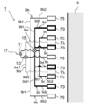
- FIG. 1 is an explanatory diagram illustrating a main part of a secondary cooling device according to an embodiment of the present invention.
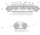
- FIG. 2 is an explanatory diagram illustrating an arrangement of water spray nozzles and an injection pattern in the secondary cooling device according to the embodiment of the present invention.
- FIG. 3 is a graph illustrating a control range of water density in the secondary cooling device according to the embodiment of the present invention.
- FIG. 4 is an explanatory diagram illustrating an outline of a general continuous casting facility.
- FIG. 1 is an explanatory diagram illustrating a main part of a secondary cooling device according to an embodiment of the present invention.
- FIG. 2 is an explanatory diagram illustrating an arrangement of water spray nozzles and an injection pattern in the secondary cooling device according to the embodiment of the present invention.
- the secondary cooling device 1 for continuously cast slabs is a casting supported and guided by a plurality of guide rollers 3 in the secondary cooling zone of the continuous casting machine.
- the piece 5 is cooled by a one-fluid water spray.
- the secondary cooling device 1 corresponds to two or more types (four types in the present embodiment) of water spray nozzles 7A, 7B, 7C, and 7D having different injection flow rates, which are flow rate characteristics, and the flow rate characteristics of each water spray nozzle 7.
- a switching device for switching between a plurality of water supply lines 9a, 9b, 9c, 9d in the present embodiment, the same number of four as the type of the water spray nozzle 7) and the water supply line 9 to be used.
- a first switching valve 11, a second switching valve 13, and a third switching valve 15 are provided.
- Water spray nozzles 7A, 7B, 7C, and 7D are installed in a line in the gap between the guide rollers 3 in a direction parallel to the guide rollers 3 to form a cooling zone.
- the guide roller 3 gives the slab 5 a pulling force in the casting direction by rotating the slab 5 by sandwiching it vertically.
- a plurality of guide rollers 3 are arranged at predetermined intervals in one segment.
- a predetermined gap is provided between the guide rollers 3 adjacent to each other in the casting direction, and the water spray nozzle 7 is installed in this gap.
- it depends on the scale of the equipment for example, in the horizontal band, nearly 100 guide rollers 3 are arranged at predetermined intervals in the casting direction, and a plurality of (for example, 10) guide rollers 3 are one segment. It is possible to control the flow rate as one unit. For example, 10 segments are installed in the horizontal zone.
- the four types of water spray nozzles 7A, 7B, 7C, and 7D (water spray nozzle group) are installed in a line in the gap of the guide roller 3 in a direction parallel to the rotation axis of the guide roller 3.
- the zone cooled by these water spray nozzles is called a cooling zone.
- One or more cooling zones are installed in the horizontal zone.
- two water spray nozzles 7A, three water spray nozzles 7B, two water spray nozzles 7C, and four water spray nozzles 7D are shown. However, these numbers do not indicate the total number of nozzles to be installed, and some of them are omitted. In fact, no matter which water spray nozzle 7 is selected, the slabs The number of each water spray nozzle 7 is set so as to cover the entire width in the width direction of 5.
- the positions where the slabs 5 are arranged in the width direction are different for each type.
- the injection angles of the water spray nozzles 7 are different so that the water spray nozzles 7 of different arrangements can be covered without gaps in the width direction of the slab 5 regardless of the type of water spray nozzles 7 selected.
- the sprayed water spreads in a fan shape, a full cone shape, or a full angle pyramid shape, and the water density distribution on the surface to be cooled (the upper and lower surfaces of the slab sandwiched between the two guide rollers 3). It is preferable to use a nozzle having high uniformity. Therefore, the water sprayed from the water spray nozzle 7 becomes the water sprayed from the other water spray nozzles 7 so that the cooling water can be uniformly sprayed onto the surface to be cooled that the row of the water spray nozzles 7 is in charge of. It is preferable to adjust each water spray nozzle 7 so as not to interfere with each other.
- the water spray nozzle 7 in which water spreads in a fan shape it is preferable to adjust the injection direction so that the injection surfaces of the water spray nozzle 7 do not line up in a straight line.
- the water sprayed from the water spray nozzle 7 interferes with the water sprayed from another water spray nozzle 7. It is preferable to adjust the arrangement interval of each water spray nozzle 7 so that
- FIG. 3 is a graph illustrating a control range of water density in the secondary cooling device according to the embodiment of the present invention.
- the flow rate characteristics of each of the four types of water spray nozzles 7 will be described with reference to FIG.
- the vertical axis of FIG. 3 is the water density (L / (m 2 ⁇ min)), and the horizontal axis is the supply pressure (MPa).
- the water density is calculated by dividing the total amount of water (L / min) ejected from the rows of water spray nozzles 7 by the area of the surface to be cooled (m 2 ) covered by the rows of water spray nozzles 7. The value.
- the water density shown in FIG. 3 is the average water density of each type of water spray nozzle 7, for example, if three water spray nozzles 7A are provided.
- the water density of the water spray nozzles 7A, 7B, 7C, and 7D is A: 50 to 150 (L / (m 2 x min)), respectively, when the supply pressure is in the range of 0.1 to 0.5 (MPa).
- the water spray nozzle 7A when the water spray nozzle 7A is selected and the supply pressure is 0.1 (MPa), the minimum water density is 50 (L / (m 2 ⁇ min)), and the water spray nozzle 7D is selected and supplied.
- the pressure is 0.5 (MPa)
- the maximum water density is 2000 (L / (m 2 ⁇ min)). That is, the water spray nozzle 7 of the present embodiment can have a pressure ratio of 5 times and a turndown ratio of 40 times.
- four types of water supply lines 9 are provided in order to supply water at a flow rate corresponding to the four types of flow rate characteristics of the water spray nozzles 7A, 7B, 7C, and 7D.
- the water supply line 9a that supplies water to the water spray nozzle 7A has a header portion 9a1 that is directly or indirectly connected to the main supply line 17, and a water spray nozzle 7A whose base end is connected to the header portion 9a1 and is connected to the tip. It is provided with a plurality of branch pipes 9a2 to which The capacity of the header portion 9a1 and the diameter of the branch pipe 9a2 are set for the header portion 9a1 and each branch pipe 9a2 according to the flow rate characteristics of the water spray nozzle 7A. The same applies to the water supply lines 9b, 9c, 9d that supply water to the water spray nozzles 7B, 7C, 7D.
- a supply pump (not shown) is connected to the main supply line 17 that supplies water to each water supply line 9.
- cooling water is supplied from the supply pump at a constant pressure equal to or higher than the pressure at which the maximum flow rate can be injected for each of the four types of water spray nozzles 7A, 7B, 7C, and 7D.
- the cooling supplied to each water spray nozzle 7 is controlled by controlling the opening degree of the valve provided in the water supply lines 9a, 9b, 9c, 9d for supplying water to the water spray nozzles 7A, 7B, 7C, 7D. Change the water pressure.
- the pressure of the supply water may be changed by changing the discharge pressure of the supply pump.
- the opening control of the valves provided in the water supply lines 9a, 9b, 9c, 9d is used. And it can be changed by the drive control of the supply pump.
- the first switching valve 11 to the third switching valve 15 are valves for switching which water supply line 9 the water flows through, and are composed of a four-way valve. By being composed of a four-way valve, it is possible to switch the flow path so that water is supplied to only one water supply line 9 and water is not supplied to the other three water supply lines 9.
- the water spray nozzles 7A, 7B, 7C, 7D installed in each gap of the guide roller 3 are 1 depending on the cooling condition, that is, the required water volume density.
- the type is selected, and the flow rate of water corresponding to the selected water spray nozzle 7 is supplied from the supply pump via the water supply lines 9a, 9b, 9c, 9d.
- cooling water having a pressure of 0.1 (MPa) is supplied to the water supply line 9a and is supplied from the water spray nozzle 7A. It is discharged.
- the cooling water is supplied from the supply pump to the water supply line 9a at a discharge pressure of 0.5 (MPa), and control is performed to reduce the opening degree of a valve (not shown) installed in the water supply line 9a.
- the pressure is reduced to 1 (MPa) and supplied to the water spray nozzle 7A.
- the operation of the first switching valve 11 to the third switching valve 15 is performed manually or automatically. In the case of automatic operation, an actuator (not shown) may be operated by a control signal of a control unit (not shown) to operate the first switching valve 11 to the third switching valve 15 according to the casting speed.
- the water spray nozzles 7A to 7D are switched from the weak cooling condition to the strong cooling condition as shown in the relationship between the supply pressure and the water density in FIG. Therefore, a turndown ratio of 40 times can be realized while suppressing the pressure ratio to 5 times. As a result, high-speed casting can be stably realized without requiring a large capital investment or operating cost, and good surface texture and internal quality of the slab 5 can be obtained.
- all the segments constituting the horizontal band have the same specifications so that any segment can be cooled with a large turndown ratio, and cooling control can be performed in the same manner at any position in the casting direction. It is preferable to do so.
- the turndown ratio that can handle a wide range of cooling conditions as described above is preferably 20 times or more (50 to 1000 L / (m 2 x min)), and is about 40 times (50 to 2000 L / (m 2 x min)). ) Is more preferable, as examined by the inventor. [Embodiment 2] Next, the secondary cooling method using the secondary cooling device 1 described in the first embodiment will be described.
- a suitable secondary cooling method can be realized even when the casting speed changes, but by using the secondary cooling device 1, the amount of cooling water can be further reduced.
- the casting speed can be increased while reducing the amount. This point will be described below.
- the slab 5 is sprayed with water (water one-fluid spray or water-air two-fluid mixed mist) to complete solidification from the vertical band 23 to the horizontal band 31 to the center after leaving the mold.
- Secondary cooling using (spray) is carried out.
- the strength of the shell is secured by injecting a large flow rate of water in the vertical band 23 from directly under the mold to entering the curved band 27 to carry out strong cooling.
- the cooling is weakened, and the surface temperature is raised (reheated) by heat conduction from the high temperature portion inside. Then, in the straightening zone, the surface temperature is adjusted so as to be above the embrittlement temperature range to avoid the occurrence of lateral cracks.
- nucleate boiling is a boiling state in which bubbles are generated around the foaming point and the coolant can take very high heat from the object to be cooled.
- the boiling state that has not reached nucleate boiling is called membrane boiling.
- Membrane boiling is a boiling state in which a vapor film is formed at the boundary between the coolant and the object to be cooled, which becomes a heat insulating layer, and the amount of heat that the coolant can take from the object to be cooled is small.
- the inventor found that 500 L / (m 2 ⁇ min) or more is required. It was also found that since the flow rate dependence of the cooling capacity becomes small in the nucleate boiling state, it is not necessary to excessively increase the cooling water supply capacity, and the water density may be 2000 L / (m 2 ⁇ min) or less.
- the nucleate boiling state is realized with a large flow rate of cooling water and the surface temperature of the slab is lowered, the nucleate boiling can be maintained without injecting a large amount of cooling water. Therefore, when the total amount of cooling water that can be used in the entire continuous casting machine is limited, the water amount density in the subsequent stage of the strong cooling zone may be reduced to less than 500 L / (m 2 ⁇ min). However, as a result of the examination by the inventors, it was also found that the nucleate boiling state cannot be stably maintained unless the water density is 50 L / (m 2 ⁇ min) or more.
- the amount of cooling water is reduced by performing strong cooling in the nucleate boiling state at a large flow rate in the previous stage and strong cooling at a small flow rate that maintains the nucleate boiling in the latter stage.
- the casting speed can be increased.
- the secondary cooling method for the continuously cast slab of the present embodiment is continuously composed of the vertical band 23, the bent portion 25, the curved band 27, the straightening section 29, and the horizontal band 31 from the upstream side in the casting direction.
- This is a method for cooling a continuously cast slab in which the slab 5 is secondarily cooled by using the secondary cooling device 1 for the continuously cast slab according to the first embodiment in the secondary cooling zone of the casting machine.
- the section on the upstream side in the casting direction in the horizontal zone 31 of the secondary cooling zone is a strong water cooling section in which the cooling water is injected to cool the slab 5 under the condition that the injected cooling water is in a nuclear boiling state on the surface of the slab.
- the water volume density of the cooling water is reduced, and the boiling state of the coolant on the slab surface is maintained at nuclear boiling. It is a weak water cooling section.
- nucleate boiling As a strong water cooling section that realizes nucleate boiling, it is sufficient that there is one minimum water amount control section that can individually control the water amount density in the uppermost stream portion of the horizontal zone 31. If the nucleate boiling is realized, in the subsequent sections, it is sufficient to cool with the minimum water density for maintaining the nucleate boiling, whereby the cooling by the nucleate boiling can be stably performed.
- cameras will be installed in each section to monitor the amount of water smoke generated by visual observation or measurement with a transmissometer.
- the threshold value of the amount of water smoke generated to distinguish between nucleate boiling and membrane boiling is obtained in advance by an experiment, and by confirming whether or not the amount of water smoke generated exceeds the threshold value, the nucleate boiling state is set in a predetermined section. You can check if you have achieved it. Then, if the nucleate boiling state has not been achieved, the amount of cooling water is adjusted to be increased. This ensures that the nucleate boiling state can be achieved and maintained.
- the fluid temperature and the solid temperature are locally equal at the point of contact between them. Since the temperature of liquid water rises only to the boiling point under atmospheric pressure, it is considered that the surface temperature of the slab is also about 100 ° C. if nucleate boiling is realized. Therefore, the nucleate boiling state is achieved by measuring the temperature of the slab surface and the surrounding cooling water using a contact-type thermometer having a small probe and confirming that the temperature is stable at around 100 ° C. Can be confirmed if has been achieved. Then, if the nucleate boiling state has not been achieved, the amount of cooling water is adjusted to be increased. This ensures that the nucleate boiling state can be achieved and maintained.
- each segment constituting the horizontal band 31 By making the design of each segment constituting the horizontal band 31 common, it is possible to control a wide jet water amount range with the same configuration, and further, it is possible to efficiently maintain the continuous casting machine.
- the range of the strong water cooling section differs depending on the slab thickness and steel type, it is preferable that the range can be flexibly changed in the casting direction, that is, the longitudinal direction of the slab 5.
- the secondary cooling device 1 capable of obtaining a large turndown ratio is installed in all the segments constituting the horizontal band 31.
- the present invention is produced by manufacturing a slab 5 using a vertical bending type continuous casting machine (see FIG. 4) in which the secondary cooling device 1 (see FIGS. 1 and 2) of the first embodiment is installed in a horizontal band 31. An example in which the effect of is confirmed will be described.
- the water spray nozzle 7 was designed to use four types, but in some examples, the nozzle types used are limited.
- the machine length of the continuous casting machine is 45 m, and a thermometer and a gas cutting machine 33 for measuring the temperature distribution on the surface of the slab are installed at the machine end.
- the slab 5 was manufactured by changing the cooling conditions, casting speed, and slab thickness, and the temperature unevenness during cooling, the surface texture and internal defects after casting, and the manufacturing cost were evaluated.
- Comparative Example 1 and Examples 1 and 2 235 mm thick slabs 5 were manufactured under the conditions of the prior art and the conditions to which the technique of the present invention was applied, respectively.
- Comparative Example 1 a section was set in which cooling was performed by a one-fluid spray and cooling was performed under a large flow rate condition on the way in order to increase the casting speed.
- the minimum value of the set water density was 10 L / (m 2 ⁇ min)
- the maximum value was 100 L / (m 2 ⁇ min)
- the target turndown ratio was 10 times.
- Example 1 the technique of the present invention is applied to use two types of water spray nozzles and a water supply line 9, and the water supply pressure ratio is 5 times and the turndown ratio is 20 times (minimum 50 L / (m 2). ⁇ min) to a maximum of 1000 L / (m 2 ⁇ min)) could be stably realized. Since the strong cooling conditions with a larger flow rate were stably realized than in the case of manufacturing using the prior art, the upper limit of the casting speed could be increased from 1.8 mpm to 2.7 mmp. Inspection after manufacturing revealed no defects such as cracks. In addition, because it is a one-fluid spray, it does not require an air compressor, and equipment installation costs and operating costs can be reduced.
- Example 2 In Example 2, four types of nozzles and pipes are used, and the water supply pressure ratio is 5 times and the turndown ratio is 40 times (minimum 50 L / (m 2 ⁇ min) to maximum 2000 L / (m 2 ⁇ min)). It was possible to realize it stably. Since the strong cooling conditions with a large flow rate were stably realized as compared with the case of manufacturing using the conventional technique, the upper limit of the casting speed could be further increased from 1.8 mpm to 3.0 mpm. Inspection after manufacturing revealed no defects such as cracks.
- Comparative Examples 2 and 3 and Examples 3 and 4 are examples in which the slab thickness was changed to 200 mm and 260 mm under the same cooling conditions as in Comparative Example 1 and Example 2, respectively.
- Example 4 the maximum casting speed was 2.8 mpm, which was faster than the maximum of 1.3 mpm in Comparative Example 3, and it was possible to manufacture without causing defects.
- Comparative Example 4 is a study result when one kind of two-fluid spray is used.
- the cooling water supply pressure ratio is 30 times and the turndown ratio is 20 times (minimum 10 L / (m 2 x min) to maximum 200 L / (m 2 x min)), and Comparative Examples 1 to 1 to It was found that a high turndown can be achieved with a smaller pressure ratio than 3.
- Comparative Example 5 is a method of switching between one-fluid spray and two-fluid spray, and a higher turndown ratio (20 times) can be realized with a lower pressure ratio (5 times) than that of Comparative Example 4. In this case as well, the cost was inferior to that of the examples, so the introduction of equipment was postponed.
- Comparative Example 6 is an example in which two types of one-fluid spray nozzles are used to achieve a turndown ratio of 20 times (minimum 50 L / (m 2 ⁇ min) to maximum 1000 L / (m 2 ⁇ min)) at a pressure ratio of 5 times.
- the distance between the guide rolls was widened, and two types of nozzles were arranged in two rows parallel to the rolls.
- Experiments were conducted by introducing this cooling device only in some segments of the secondary cooling zone where a high turndown ratio is required.
- the range of water density and the turndown ratio were the same as in Example 1, as a result of arranging the spray nozzles in two rows, the roll interval became wider and the bulging amount became larger. Therefore, when the slab 5 after casting was inspected, internal cracks were observed, and the degree of central segregation also deteriorated.
- Example 5 is an example in which two types of one-fluid spray nozzles are used and the pressure ratio is doubled and the turndown ratio is 40 times (minimum 50 L / (m 2 ⁇ min) to maximum 2000 L / (m 2 ⁇ min)). Is. However, in this example, the control range of the cooling capacity was limited to two levels, weak cooling and strong cooling, so the supply pressure ratio could be reduced by 5 to 2 times by reducing the flow rate control range of each water spray nozzle. ..
- control range of the flow rate of the entire cooling device is intermittent.
- the controllability of the cooling capacity against fluctuations in the casting speed is inferior to that of the first and second embodiments, high-speed casting of the same degree is possible, and defects are also observed in the slab 5 after production. There wasn't.
- Example 6 is an example in which two types of one-fluid spray nozzles are used and the pressure ratio is doubled and the turndown ratio is 11 times (minimum 50 L / (m 2 ⁇ min) to maximum 550 L / (m 2 ⁇ min)). Is.
- the maximum water density was reduced to the extent that nucleate boiling could be maintained, so the upper limit of the casting speed was 2.5 mpm, which was higher than in Examples 1, 2, and 5 having the same slab thickness of 235 mm.
- the cost is low. There was no operational problem, and no defects were found in the slab 5 after production.
- Example 7 is an example in which two types of one-fluid spray nozzles are used and the pressure ratio is 5 times and the turndown ratio is 5 times (minimum 400 L / (m 2 ⁇ min) to maximum 2000 L / (m 2 ⁇ min)). Is.
- Example 8 was a turndown ratio of 20 times 5 times pressure ratio by using two kinds of single-fluid spray nozzle (Min 45L / (m 2 ⁇ min) ⁇ up 900L / (m 2 ⁇ min) ) Example Is.
- Min 45L / (m 2 ⁇ min) ⁇ up 900L / (m 2 ⁇ min) Example Is.
- the upper limit of the casting speed was 2.6 mpm, although the slab had slight surface cracks.
- the secondary cooling device 1 capable of increasing the turndown ratio, the controllability of the secondary cooling with respect to the fluctuation of the casting speed is improved, and the slab of high quality while increasing the casting speed. It was demonstrated that the production of 5 can be realized.
- the present invention is applied to the horizontal zone 31 is shown, but it may be applied to another cooling zone on the upstream side of the horizontal zone 31, or may be applied across a plurality of cooling zones. ..
Abstract
Description
(2)前記水供給ラインの数は、前記水スプレーノズルの種類と同数である、(1)に記載の連続鋳造鋳片の二次冷却装置。
(3)前記二種類以上の水スプレーノズルのうち、最も噴射流量の多いスプレーノズルによって噴射される水の水量密度は、最も噴射流量が少ないスプレーノズルによって噴射される水の水量密度の20倍以上である、(1)または(2)に記載の連続鋳造鋳片の二次冷却装置。
(4)前記二種類以上の水スプレーノズルのうち、最も噴射流量の多いスプレーノズルによって噴射される水の水量密度は500L/(m2×min)以上2000L/(m2×min)以下であり、最も噴射流量が少ないスプレーノズルによって噴射される水の水量密度は50L/(m2×min)以上500L/(m2×min)未満である、(1)から(3)のいずれか1つに記載の連続鋳造鋳片の二次冷却装置。
(5)鋳造方向上流側から、垂直帯、曲げ部、湾曲帯、矯正部、水平帯の順で構成される前記連続鋳造機の二次冷却帯において、前記冷却ゾーンが、前記水平帯内に1ゾーン以上設置される、(1)から(4)のいずれか1つに記載の連続鋳造鋳片の二次冷却装置。
(6)(5)に記載の連続鋳造鋳片の二次冷却装置を用いて鋳片を二次冷却する連続鋳造鋳片の冷却方法であって、前記水平帯における鋳造方向上流側区間を、噴射された水が鋳片表面で核沸騰状態となる条件で水を噴射して鋳片を冷却する強水冷区間とし、かつ、前記強水冷区間より鋳造方向下流側で前記水平帯末端までの区間を、前記強水冷区間よりも水量密度を低下させ、かつ鋳片表面における冷却液の沸騰状態を核沸騰に維持する弱水冷区間とする、連続鋳造鋳片の二次冷却方法。 (1) A secondary cooling device for continuously cast slabs that cools slabs supported and guided by a plurality of guide rollers with a one-fluid water spray in the secondary cooling zone of the continuous casting machine, and has different flow rate characteristics. It is provided with more than one type of water spray nozzle, a plurality of water supply lines that supply water at a flow rate according to the flow rate characteristics of each water spray nozzle, and a switching device that switches the water supply line to be used, and the flow rate characteristics are different. A secondary cooling device for continuously cast slabs, which has a cooling zone in which two or more types of water spray nozzles are arranged in a row in a gap between the guide rollers in a direction parallel to the rotation axis of the guide rollers.
(2) The secondary cooling device for continuously cast slabs according to (1), wherein the number of the water supply lines is the same as that of the type of the water spray nozzle.
(3) Of the two or more types of water spray nozzles, the water volume density of the water sprayed by the spray nozzle having the largest spray flow rate is 20 times or more the water volume density of the water sprayed by the spray nozzle having the lowest spray flow rate. The secondary cooling device for the continuous cast slab according to (1) or (2).
(4) Of the two or more types of water spray nozzles, the water volume density of the water sprayed by the spray nozzle having the largest injection flow rate is 500 L / (m 2 × min) or more and 2000 L / (m 2 × min) or less. The water volume density of the water ejected by the spray nozzle having the smallest injection flow rate is 50 L / (m 2 × min) or more and less than 500 L / (m 2 × min), any one of (1) to (3). A secondary cooling device for continuously cast slabs according to.
(5) In the secondary cooling zone of the continuous casting machine, which is composed of a vertical band, a bending part, a curved band, a straightening part, and a horizontal band from the upstream side in the casting direction, the cooling zone is located in the horizontal band. The secondary cooling device for continuously cast slabs according to any one of (1) to (4), which is installed in one or more zones.
(6) A method for cooling a continuously cast slab in which the slab is secondarily cooled by using the secondary cooling device for the continuously cast slab according to (5), wherein a section on the upstream side in the casting direction in the horizontal band is defined. A strong water-cooled section in which water is injected to cool the slab under the condition that the injected water is in a nuclear boiling state on the surface of the slab, and a section from the strong water-cooled section to the end of the horizontal zone on the downstream side in the casting direction. A secondary cooling method for continuously cast slabs, wherein the water volume density is lower than that of the strong water cooling section, and the boiling state of the coolant on the surface of the slab is maintained at nuclear boiling.
図1は、本発明の実施の形態に係る二次冷却装置の要部を説明する説明図である。図2は、本発明の実施の形態に係る二次冷却装置における水スプレーノズルの配置及び噴射パターンを説明する説明図である。 [Embodiment 1]
FIG. 1 is an explanatory diagram illustrating a main part of a secondary cooling device according to an embodiment of the present invention. FIG. 2 is an explanatory diagram illustrating an arrangement of water spray nozzles and an injection pattern in the secondary cooling device according to the embodiment of the present invention.
[実施の形態2]
次に、上記の実施の形態1で説明した二次冷却装置1を用いた二次冷却方法について説明する。 The turndown ratio that can handle a wide range of cooling conditions as described above is preferably 20 times or more (50 to 1000 L / (m 2 x min)), and is about 40 times (50 to 2000 L / (m 2 x min)). ) Is more preferable, as examined by the inventor.
[Embodiment 2]
Next, the secondary cooling method using the

比較例1および実施例1、2では、235mm厚の鋳片5をそれぞれ従来技術の条件と本発明の技術を適用した条件とで製造した。
In Comparative Example 1 and Examples 1 and 2, 235 mm
3 ガイドローラー
5 鋳片
7A、7B、7C、7D 水スプレーノズル
9a、9b、9c、9d 水供給ライン
9a1、9b1、9c1、9d1 ヘッダ部
9a2、9b2、9c2、9d2 分岐管
11 第1切換バルブ
13 第2切換バルブ
15 第3切換バルブ
17 主供給ライン
<従来例>
21 鋳型
23 垂直帯
25 曲げ部
27 湾曲帯
29 矯正部
31 水平帯
33 ガス切断機 1
21
Claims (6)
- 連続鋳造機の二次冷却帯において、複数のガイドローラーによって支持案内される鋳片を一流体水スプレーで冷却する連続鋳造鋳片の二次冷却装置であって、
流量特性の異なる二種類以上の水スプレーノズルと、
各水スプレーノズルの流量特性に応じた流量の水を供給する複数の水供給ラインと、
使用する水供給ラインを切り換える切換装置と、
を備え、
前記流量特性の異なる二種類以上の水スプレーノズルが、前記ガイドローラー間の隙間に、前記ガイドローラーの回転軸と平行な方向に一列に並べて設置されている冷却ゾーンを有する、連続鋳造鋳片の二次冷却装置。 A secondary cooling device for continuously cast slabs that cools slabs supported and guided by a plurality of guide rollers with a one-fluid water spray in the secondary cooling zone of a continuous casting machine.
Two or more types of water spray nozzles with different flow characteristics,
Multiple water supply lines that supply water with a flow rate according to the flow rate characteristics of each water spray nozzle,
A switching device that switches the water supply line to be used,
With
A continuously cast slab having a cooling zone in which two or more types of water spray nozzles having different flow characteristics are arranged in a row in a gap between the guide rollers in a direction parallel to the rotation axis of the guide rollers. Secondary cooling device. - 前記水供給ラインの数は、前記水スプレーノズルの種類と同数である、請求項1に記載の連続鋳造鋳片の二次冷却装置。 The secondary cooling device for continuously cast slabs according to claim 1, wherein the number of the water supply lines is the same as that of the type of the water spray nozzle.
- 前記二種類以上の水スプレーノズルのうち、最も噴射流量の多いスプレーノズルによって噴射される水の水量密度は、最も噴射流量が少ないスプレーノズルによって噴射される水の水量密度の20倍以上である、請求項1または請求項2に記載の連続鋳造鋳片の二次冷却装置。 Of the two or more types of water spray nozzles, the water volume density of the water sprayed by the spray nozzle having the highest spray flow rate is 20 times or more the water volume density of the water sprayed by the spray nozzle having the lowest spray flow rate. The secondary cooling device for continuously cast slabs according to claim 1 or 2.
- 前記二種類以上の水スプレーノズルのうち、最も噴射流量の多いスプレーノズルによって噴射される水の水量密度は500L/(m2×min)以上2000L/(m2×min)以下であり、最も噴射流量が少ないスプレーノズルによって噴射される水の水量密度は50L/(m2×min)以上500L/(m2×min)未満である、請求項1から請求項3のいずれか1項に記載の連続鋳造鋳片の二次冷却装置。 Of the two or more types of water spray nozzles, the water volume density of the water ejected by the spray nozzle having the largest injection flow rate is 500 L / (m 2 × min) or more and 2000 L / (m 2 × min) or less, and is the most injected. The method according to any one of claims 1 to 3, wherein the water volume density of the water sprayed by the spray nozzle having a small flow rate is 50 L / (m 2 × min) or more and less than 500 L / (m 2 × min). Secondary cooling device for continuously cast slabs.
- 鋳造方向上流側から、垂直帯、曲げ部、湾曲帯、矯正部、水平帯の順で構成される前記連続鋳造機の二次冷却帯において、前記冷却ゾーンが、前記水平帯内に1ゾーン以上設置される、請求項1から請求項4のいずれか1項に記載の連続鋳造鋳片の二次冷却装置。 In the secondary cooling zone of the continuous casting machine composed of a vertical band, a bent part, a curved band, a straightening part, and a horizontal band from the upstream side in the casting direction, the cooling zone is one or more zones in the horizontal band. The secondary cooling device for continuously cast slabs according to any one of claims 1 to 4, which is installed.
- 請求項5に記載の連続鋳造鋳片の二次冷却装置を用いて鋳片を二次冷却する連続鋳造鋳片の冷却方法であって、
前記水平帯における鋳造方向上流側区間を、噴射された水が鋳片表面で核沸騰状態となる条件で水を噴射して鋳片を冷却する強水冷区間とし、かつ、前記強水冷区間より鋳造方向下流側で前記水平帯末端までの区間を、前記強水冷区間よりも水量密度を低下させ、かつ鋳片表面における冷却液の沸騰状態を核沸騰に維持する弱水冷区間とする、連続鋳造鋳片の二次冷却方法。 A method for cooling a continuously cast slab, wherein the slab is secondarily cooled by using the secondary cooling device for the continuously cast slab according to claim 5.
The section on the upstream side in the casting direction in the horizontal zone is a strong water-cooled section in which water is injected to cool the slab under the condition that the injected water is in a nuclear boiling state on the surface of the slab, and casting is performed from the strong water-cooled section. Continuous casting in which the section to the end of the horizontal zone on the downstream side in the direction is a weak water-cooled section in which the water volume density is lower than that in the strong water-cooled section and the boiling state of the coolant on the slab surface is maintained at nuclear boiling. Secondary cooling method for pieces.
Priority Applications (3)
| Application Number | Priority Date | Filing Date | Title |
|---|---|---|---|
| CN202080054486.0A CN114173958A (en) | 2019-08-02 | 2020-07-30 | Secondary cooling device and secondary cooling method for continuous casting of cast piece |
| JP2021537278A JP7131707B2 (en) | 2019-08-02 | 2020-07-30 | SECONDARY COOLING APPARATUS AND SECONDARY COOLING METHOD FOR CONTINUOUS CAST SMART |
| KR1020227002955A KR102629986B1 (en) | 2019-08-02 | 2020-07-30 | Secondary cooling device and secondary cooling method for continuous casting cast steel |
Applications Claiming Priority (2)
| Application Number | Priority Date | Filing Date | Title |
|---|---|---|---|
| JP2019-142691 | 2019-08-02 | ||
| JP2019142691 | 2019-08-02 |
Publications (1)
| Publication Number | Publication Date |
|---|---|
| WO2021024920A1 true WO2021024920A1 (en) | 2021-02-11 |
Family
ID=74504068
Family Applications (1)
| Application Number | Title | Priority Date | Filing Date |
|---|---|---|---|
| PCT/JP2020/029328 WO2021024920A1 (en) | 2019-08-02 | 2020-07-30 | Continuously cast slab secondary cooling device and secondary cooling method |
Country Status (5)
| Country | Link |
|---|---|
| JP (1) | JP7131707B2 (en) |
| KR (1) | KR102629986B1 (en) |
| CN (1) | CN114173958A (en) |
| TW (1) | TWI764216B (en) |
| WO (1) | WO2021024920A1 (en) |
Cited By (1)
| Publication number | Priority date | Publication date | Assignee | Title |
|---|---|---|---|---|
| CN114672628A (en) * | 2022-03-30 | 2022-06-28 | 东北大学 | Slab surface quenching system and process based on continuous casting machine tail end |
Citations (3)
| Publication number | Priority date | Publication date | Assignee | Title |
|---|---|---|---|---|
| JPS5211012U (en) * | 1975-07-11 | 1977-01-26 | ||
| JPS6277162A (en) * | 1985-09-30 | 1987-04-09 | Hitachi Zosen Corp | Ingot cooler for continuous casting installation |
| JP2019034342A (en) * | 2017-08-18 | 2019-03-07 | レヒラー ゲゼルシャフト ミット ベシュレンクテル ハフツング | Appliance and method of spraying for cooling metal strand in continuous casting machine |
Family Cites Families (15)
| Publication number | Priority date | Publication date | Assignee | Title |
|---|---|---|---|---|
| CA936328A (en) * | 1971-09-30 | 1973-11-06 | J. English Christopher | Method and apparatus for continuous casting of metal strips |
| JPS52128836A (en) | 1976-04-21 | 1977-10-28 | Hitachi Shipbuilding Eng Co | Cooling device in continuous casting equipment |
| JPS6277152A (en) * | 1985-09-30 | 1987-04-09 | Nippon Steel Corp | Method and apparatus for continuous casting of thin sheet using twin rolls |
| JPH05220550A (en) | 1992-02-14 | 1993-08-31 | Tokai Gokin Kogyo Kk | Secondary cooling device for continuous casting |
| JP3726506B2 (en) * | 1998-05-28 | 2005-12-14 | Jfeスチール株式会社 | Billet water cooling method |
| JP4055440B2 (en) * | 2001-06-13 | 2008-03-05 | Jfeスチール株式会社 | Direct-rolling method for continuous cast slabs |
| JP4089338B2 (en) | 2002-07-31 | 2008-05-28 | Jfeスチール株式会社 | Secondary cooling method and apparatus in continuous casting |
| JP2006181590A (en) * | 2004-12-27 | 2006-07-13 | Jfe Steel Kk | Mold for continuous casting and continuous casting method for steel |
| JP5609199B2 (en) * | 2010-03-25 | 2014-10-22 | Jfeスチール株式会社 | Secondary cooling method in continuous casting |
| BR112014011190B1 (en) * | 2011-11-15 | 2020-09-15 | Nippon Steel Corporation | SECONDARY COOLING MACHINE FOR CONTINUOUS INVERTING MACHINE AND SECONDARY COOLING METHOD |
| JP5825250B2 (en) * | 2012-12-25 | 2015-12-02 | Jfeスチール株式会社 | Method and apparatus for cooling hot-rolled steel strip |
| JP6079387B2 (en) * | 2013-04-02 | 2017-02-15 | 新日鐵住金株式会社 | Method and apparatus for cooling continuous cast slab |
| JP6089006B2 (en) | 2014-06-26 | 2017-03-01 | 株式会社いけうち | spray nozzle |
| CN104525885B (en) * | 2014-12-31 | 2016-06-15 | 中冶东方工程技术有限公司 | A kind of strong cold water spray system of cast steel and strong refrigerating technology |
| CN108472718B (en) * | 2016-01-29 | 2020-11-20 | 日本制铁株式会社 | Secondary cooling method and secondary cooling device for continuous casting blank |
-
2020
- 2020-07-30 JP JP2021537278A patent/JP7131707B2/en active Active
- 2020-07-30 WO PCT/JP2020/029328 patent/WO2021024920A1/en active Application Filing
- 2020-07-30 KR KR1020227002955A patent/KR102629986B1/en active IP Right Grant
- 2020-07-30 CN CN202080054486.0A patent/CN114173958A/en active Pending
- 2020-07-31 TW TW109125992A patent/TWI764216B/en active
Patent Citations (3)
| Publication number | Priority date | Publication date | Assignee | Title |
|---|---|---|---|---|
| JPS5211012U (en) * | 1975-07-11 | 1977-01-26 | ||
| JPS6277162A (en) * | 1985-09-30 | 1987-04-09 | Hitachi Zosen Corp | Ingot cooler for continuous casting installation |
| JP2019034342A (en) * | 2017-08-18 | 2019-03-07 | レヒラー ゲゼルシャフト ミット ベシュレンクテル ハフツング | Appliance and method of spraying for cooling metal strand in continuous casting machine |
Cited By (2)
| Publication number | Priority date | Publication date | Assignee | Title |
|---|---|---|---|---|
| CN114672628A (en) * | 2022-03-30 | 2022-06-28 | 东北大学 | Slab surface quenching system and process based on continuous casting machine tail end |
| CN114672628B (en) * | 2022-03-30 | 2023-03-14 | 东北大学 | Slab surface quenching system and process based on continuous casting machine tail end |
Also Published As
| Publication number | Publication date |
|---|---|
| JPWO2021024920A1 (en) | 2021-02-11 |
| TWI764216B (en) | 2022-05-11 |
| JP7131707B2 (en) | 2022-09-06 |
| TW202112467A (en) | 2021-04-01 |
| CN114173958A (en) | 2022-03-11 |
| KR102629986B1 (en) | 2024-01-25 |
| KR20220025027A (en) | 2022-03-03 |
Similar Documents
| Publication | Publication Date | Title |
|---|---|---|
| CN100475385C (en) | Straight arc casting machine alloy steel sheet billet continuous casting foot roller segment narrow surface cooling method | |
| KR101052453B1 (en) | Cooling device and cooling method of hot rolled steel strip | |
| JP5825250B2 (en) | Method and apparatus for cooling hot-rolled steel strip | |
| KR20060018254A (en) | Controllable cooling method for thick steel plate, thick steel plate manufactured by the controllable cooling method, and cooling device for the thick steel plate | |
| KR102310881B1 (en) | A cooling device for a hot-rolled steel sheet, and a cooling method for a hot-rolled steel sheet | |
| CN110802205B (en) | Control method and device for austenite grain size of continuous casting slab and product | |
| JP4604564B2 (en) | Method and apparatus for controlling cooling of thick steel plate | |
| JP5515483B2 (en) | Thick steel plate cooling equipment and cooling method | |
| WO2021024920A1 (en) | Continuously cast slab secondary cooling device and secondary cooling method | |
| US11413670B2 (en) | Cooling device and cooling method of hot-rolled steel sheet | |
| KR20200085880A (en) | Cooling device and cooling method of thick steel plate and manufacturing equipment and manufacturing method of thick steel plate | |
| TWI731415B (en) | Cooling device for hot-rolled steel sheet and cooling method for hot-rolled steel sheet | |
| JP7052931B2 (en) | Secondary cooling method for continuously cast slabs | |
| CN113546971A (en) | Apparatus for cooling long products and method for cooling long products using said apparatus | |
| JP5515440B2 (en) | Thick steel plate cooling equipment and cooling method thereof | |
| EP3981526A1 (en) | Secondary cooling method and device for continuously cast slab | |
| WO2023248632A1 (en) | Cast slab continuous casting equipment and cast slab continuous casting method | |
| KR20090104407A (en) | Method for cooling of rolled plate |
Legal Events
| Date | Code | Title | Description |
|---|---|---|---|
| 121 | Ep: the epo has been informed by wipo that ep was designated in this application |
Ref document number: 20850695 Country of ref document: EP Kind code of ref document: A1 |
|
| ENP | Entry into the national phase |
Ref document number: 2021537278 Country of ref document: JP Kind code of ref document: A |
|
| ENP | Entry into the national phase |
Ref document number: 20227002955 Country of ref document: KR Kind code of ref document: A |
|
| NENP | Non-entry into the national phase |
Ref country code: DE |
|
| 122 | Ep: pct application non-entry in european phase |
Ref document number: 20850695 Country of ref document: EP Kind code of ref document: A1 |