WO2021024320A1 - Mitral valve model and fixing jig - Google Patents
Mitral valve model and fixing jig Download PDFInfo
- Publication number
- WO2021024320A1 WO2021024320A1 PCT/JP2019/030562 JP2019030562W WO2021024320A1 WO 2021024320 A1 WO2021024320 A1 WO 2021024320A1 JP 2019030562 W JP2019030562 W JP 2019030562W WO 2021024320 A1 WO2021024320 A1 WO 2021024320A1
- Authority
- WO
- WIPO (PCT)
- Prior art keywords
- mitral valve
- model
- valve model
- fixing jig
- left atrium
- Prior art date
Links
Images


Classifications
-
- G—PHYSICS
- G09—EDUCATION; CRYPTOGRAPHY; DISPLAY; ADVERTISING; SEALS
- G09B—EDUCATIONAL OR DEMONSTRATION APPLIANCES; APPLIANCES FOR TEACHING, OR COMMUNICATING WITH, THE BLIND, DEAF OR MUTE; MODELS; PLANETARIA; GLOBES; MAPS; DIAGRAMS
- G09B23/00—Models for scientific, medical, or mathematical purposes, e.g. full-sized devices for demonstration purposes
- G09B23/28—Models for scientific, medical, or mathematical purposes, e.g. full-sized devices for demonstration purposes for medicine
- G09B23/285—Models for scientific, medical, or mathematical purposes, e.g. full-sized devices for demonstration purposes for medicine for injections, endoscopy, bronchoscopy, sigmoidscopy, insertion of contraceptive devices or enemas
-
- G—PHYSICS
- G09—EDUCATION; CRYPTOGRAPHY; DISPLAY; ADVERTISING; SEALS
- G09B—EDUCATIONAL OR DEMONSTRATION APPLIANCES; APPLIANCES FOR TEACHING, OR COMMUNICATING WITH, THE BLIND, DEAF OR MUTE; MODELS; PLANETARIA; GLOBES; MAPS; DIAGRAMS
- G09B23/00—Models for scientific, medical, or mathematical purposes, e.g. full-sized devices for demonstration purposes
- G09B23/28—Models for scientific, medical, or mathematical purposes, e.g. full-sized devices for demonstration purposes for medicine
- G09B23/30—Anatomical models
Definitions
- the present invention relates to an organ model for training mitral valve repair or mitral valve replacement.
- angina pectoris and myocardial infarction are known as heart diseases.
- heart diseases the estimated number of patients with valvular heart disease is as high as 2 million or more, and it is said that the number is increasing year by year. Of the patients with valvular heart disease, about 10,000 patients undergo surgery annually.
- mitral regurgitation is a condition in which the mitral valve's closing function deteriorates and some of the blood that should be sent from the left ventricle to the aorta flows back into the left atrium. Also called reflux disease.
- mitral regurgitation causes deviation of the leaflet, rupture of the chordae tendineae, and enlargement of the annulus.
- Treatment methods for mitral regurgitation include medical treatment that relieves symptoms and suppresses progression, and surgical treatment.
- Surgical treatment includes mitral valve replacement, which replaces the valve with an artificial valve, and mitral valve repair, which controls regurgitation by repairing the patient's own valve.
- Mitral valve repair has the advantage that the function of the heart is easily preserved because it repairs the patient's own valve.
- there is no blood coagulation around the valve and there is an advantage that it is not necessary to take an anticoagulant for a lifetime as in the case of using a mechanical valve in mitral valve replacement.
- mitral valve repair has the problem of being more difficult than mitral valve replacement.
- complete endoscopic surgery using a surgery support robot and small incision surgery called MICS minimally invasive cardiac surgery
- MICS minimally invasive cardiac surgery
- These minimally invasive surgeries not only place less strain on the patient's body than median sternotomy, which opens the chest significantly, but also allow the mitral valve to be approached from the right side of the patient's body, observing insufficiency. It has the advantage of being easy to use.
- these minimally invasive surgeries require doctors to have a high level of technical skill and experience, it is strongly desired that doctors gain a large amount of experience and improve their technical skills.
- the thoracic cavity simulator disclosed in Patent Document 1 is a device including at least a human skeleton model simulating a rib and a casing for accommodating the human skeleton model, and an opening is provided in the rib portion of the casing to form a diaphragm.
- the part can be opened and closed, and the organ model can be stored inside the ribs of the human skeleton model. According to this, it is possible to effectively train the procedure of approaching the mitral valve from between the ribs of the patient's right chest.
- the artificial organ model used for training generally has a problem that the manufacturing cost is high. Therefore, there is known a heart model in which a liquid resin is injected and cured by using an outer mold and a core that can be divided into a plurality of parts (see Patent Document 2).
- the heart model disclosed in Patent Document 2 is different from the conventional technique in which the core is crushed and discarded because the core can be divided and reused not only for the outer mold used for manufacturing but also for the core.
- the organ model can be mass-produced at low cost.
- the heart model disclosed in Patent Document 2 has a problem that the cost cannot be sufficiently reduced because it tries to accurately reproduce the shape even in a portion that is not particularly necessary in actual surgery.
- a gripping member provided with an engaging portion is used as a method of attaching the organ model to the simulator of Patent Document 1.
- the endoscope is generally inserted and accessed from the 4th intercostal space, but the mounting position of the organ model is fixed in one place and does not change. If there is, some surgeons may feel uncomfortable in the surgical field as seen from the access position.
- the thoracic cavity simulator disclosed in Patent Document 1 has a problem that the device and mechanism for adjusting the attachment position of the organ model are not sufficiently disclosed.
- the present invention enables effective and low-cost training for mitral valve repair or mitral valve replacement, and is an easy-to-use and convenient mitral valve model and fixation. It is an object of the present invention to provide a jig.
- the mitral valve model of the present invention is a mitral valve model for training endoscopic procedures of mitral valve plasty or mitral valve replacement, and the mitral valve model is ,
- the texture of the organs of the heart is reproduced or deformed. It consists of the left atrium, the mitral valve, and the left ventricle.
- the mitral valve is invisible from the outside and is covered by the left atrium. Since the mitral valve is not visible from the outside and is covered by the left atrium, the left atrium wall of the left atrium can be incised and the valve leaflets can be excised, which is a more realistic procedure. Training becomes possible.
- the left atrium and the left ventricle are both hollow, and it is preferable that at least one of the following 1) to 3) is set.
- 1) The leaflet provided on the mitral valve is in a deviant state.
- 2) The chordae tendineae connecting the leaflet provided in the mitral valve and the tip of the papillary muscle provided in the left ventricle are in a ruptured state.
- 3) The distance between the leaflet provided on the mitral valve and the tip of the papillary muscle is 3 to 7 mm.
- the deviation state may be provided on the anterior leaflet or the posterior leaflet.
- the deviant state is used to include not only deviation in a narrow sense but also hypertrophy of the valve leaflets.
- the tip of the papillary muscle is formed round in order to more realistically reproduce the torn state of the chordae tendineae.
- the more preferable distance between the valve leaflet and the tip of the papillary muscle in 3) above is 5 mm.
- the surface layer of the left atrium preferably reproduces or deforms the hardness and thickness of the heart organ, and can be grasped and incised by an instrument used in the procedure. Since it is necessary to make an incision in the left atrium wall when performing mitral valve repair or mitral valve replacement procedure training, by reproducing the hardness and thickness, training such as organ grasping and incision becomes more realistic. It can be carried out. In addition, by deforming the hardness or thickness of the parts that are not related to the procedure such as grasping and incision, it is possible to manufacture at low cost.
- the shape of the left atrium is preferably a substantially spherical shape that is deformed based on the scope image in the actual endoscopic procedure.
- the material constituting the left atrium contains fine bubbles in order to reproduce the texture. Due to the inclusion of fine bubbles, it is difficult to slip when gripped with forceps or the like, and the flexibility is increased to facilitate gripping. Further, since the mitral valve portion is subjected to a procedure of stretching and suturing the incised surface after excising the lesion, the mitral valve portion may be a material containing fibers in order to increase the strength.
- the material constituting the left ventricle may not contain fine bubbles and fibers.
- the material constituting the left ventricle may not contain fine bubbles and fibers.
- a mounting mechanism for mounting on a fixing jig for fixing an organ to the thoracic cavity simulator is provided below the left ventricle.
- the mounting mechanism include through holes, concave portions, convex portions, and the like.
- the mitral valve model fixing jig of the present invention is a fixing jig for attaching and fixing the above-mentioned mitral valve model, and the fixing jig is for engaging with the spine portion inside the thoracic cavity simulator. It has a pedestal part with an engagement mechanism and a fixing part for fixing the mitral valve model, and the fixing part is fixed by sliding the pedestal part onto the spine part with the mitral valve model attached and fixed. It is provided with a mechanism capable of further fine-tuning the position by sliding it in the longitudinal direction of the spine portion from the moved position.
- the engagement mechanism for engaging with the spine part inside the thoracic cavity simulator is a convex or concave engaging part, and the concave or convex engaging part provided at the spine part inside the thoracic cavity simulator. It is preferable to engage.
- the fixing portion has the outward direction of the front surface of the left atrium of the mitral valve model, the longitudinal direction of the spine portion and the direction toward the head, and the direction orthogonal to the direction It is equipped with a rotary table mechanism that can be finely adjusted from the center of the thoracic cavity simulator to the direction on the right hand side.
- a rotary table mechanism that can finely adjust the orientation of the mitral valve model within a range of 90 ° from the patient's head side to the right side, a surgical field closer to the actual surgery can be obtained.
- a rotary table mechanism that can finely adjust the orientation of the mitral valve model within a range of 90 ° from the patient's head side to the right side
- the mitral valve model and the fixing jig of the present invention effective and low-cost training for mitral valve plasty or mitral valve replacement is possible, and the mitral valve is easier to handle and more convenient. It has the effect of being able to be used as a cap valve model and a fixing jig.
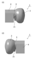
- FIG. 1 shows a perspective view of the mitral valve model of Example 1.
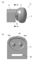
- 2 to 4 are external views of the mitral valve model of the first embodiment, FIG. 2 (1) is a front view, FIG. 2 (2) is a rear view, and FIG. 3 (1) is a plan view. 3 (2) is a bottom view, FIG. 4 (1) is a left side view, and FIG. 4 (2) is a right side view.
- the mitral valve model 1 comprises a left atrium 2, a mitral valve 3, and a left ventricle 4.
- the mitral valve model 1 reproduces or deforms the flattened shape of the heart in a state where the patient is equipped with an artificial heart-lung machine pump, blood is drawn from the heart, and gas is added and pressure is applied by an endoscopic procedure. It is a realistic reproduction of the shape seen from the scope of the endoscope.
- the left atrium 2, the mitral valve 3, and the left ventricle 4 are molded separately and then adhered to form the mitral valve model 1, but may be integrally molded.
- the appearance of the left atrium 2 has a rounded shape based on an inverted triangle with rounded corners when viewed from the front, and is substantially circular in shape. .. Further, as shown in FIGS. 1 to 4, the overall shape is a substantially spherical shape, and is connected to the mitral valve portion 2. As shown in FIG. 4 (1), the left atrial region 2 is provided with a left atrial appendage 21. Generally, at the time of heart surgery such as mitral valve repair, left atrial appendage occlusion is also performed at the same time to reduce the risk of thromboembolism. Therefore, by providing the left atrial appendage 21, it is possible to perform the procedure training of the left atrial appendage occlusion at the same time.
- the appearance of the left ventricular portion 4 has a substantially rectangular parallelepiped shape as shown in FIG. 2 (2), FIG. 3 or FIG. 4, and is connected to the mitral valve portion 2.
- the upper end of the left ventricular portion 4 is formed with rounded corners, and as will be described later, the left ventricular wall is reproduced.
- a through hole 42 is formed in the lower part of the left ventricular portion 4, and can be easily attached to the mitral valve fixing jig 5 described later.
- the lower end portion of the left ventricular portion 4 has a flat shape as shown in FIG. 2 or FIG. There is.
- the mitral valve portion 3 is not visible in appearance and is covered with the left atrium portion 2. Therefore, since the mitral valve portion 3 appears by incising the left atrium portion 2 in the training, more realistic training is possible.
- FIG. 5 (1) is a left side view of the mitral valve model
- FIG. 5 (2) shows a cross-sectional view taken along the line AA in FIG. 5 (1).
- the left atrium portion 2 is formed by the left atrium wall 2a, and the left atrial appendage 21 is provided at the lower left position in the front view.
- the mitral valve portion 3 is composed of an anterior leaflet 3a, a posterior leaflet 3b and an annulus 3c, and the left atrium 2 is connected to the mitral valve annulus 3 at the position of the annulus 3c.
- the mitral valve part 3 does not reproduce the mitral valve in a normal human body, and the center of the posterior leaflet 3b of the valve leaflets is in a deviant state, and an example of a lesion of mitral regurgitation is It has been reproduced.
- the center of the posterior leaflet 3b is in a deviant state, but the lesion is not limited to such a position.
- the anterior leaflet 3a may be in a deviant state, or the left and right sides of the posterior leaflet 3b are in a deviant state. It may be a lesion. By changing the position of the lesion, various variations of training become possible.
- FIG. 6 (1) is a left side view of the mitral valve model
- FIG. 6 (2) shows a sectional view taken along line BB in FIG. 6 (1)
- FIG. 7 (1) is a front view of the mitral valve model
- FIG. 7 (2) shows a sectional view taken along line CC in FIG. 7 (1).
- the left ventricular portion 4 is surrounded by the left ventricular wall 4a, the inside is hollow, and the papillary muscles (41a, 41b) are provided. There is. No chordae tendineae are provided at the tips of the papillary muscles (41a, 41b), and the state in which the chordae tendineae are torn is reproduced.
- the distance P between the mitral valve portion 3 and the papillary muscle 41a shown in FIG. 7 (2) is 5 mm. This distance is a realistic reproduction of the distance between the mitral valve and the papillary muscle during actual surgery. Further, the tips of the papillary muscles (41a, 41b) are formed to be round, and the actual shape of the papillary muscles is realistically reproduced in this respect as well. As shown in FIG. 7 (2), the internal space of the left atrium 2 is widely provided, which is the same as the state in which the annulus 3c is threaded after the left atrium wall 2a is incised in the procedure training. The state can be reproduced.
- the material of the mitral valve model 1 will be described.
- the left atrium 2 needs to make an incision in the left atrium wall 2a in order to perform mitral valve repair or the like, the texture when the left atrium wall 2a is picked up with a forceps or the like is the actual left atrium. Must be similar to a wall.
- the mitral valve portion 3 needs to be made of a material that can withstand suturing because it is necessary to stretch and suture the cut surface after the leaflet is cut off.
- the entire left ventricle portion including the left ventricle wall 4a is formed of the polyvinyl alcohol resin, but the left atrium wall 2a of the left atrium portion 2 has fine bubbles (shown) in the polyvinyl alcohol resin. It is made of a material that contains. Therefore, the material of the left atrium wall 2a is less slippery than the material of the left ventricle wall 4a and is more flexible, so that it is easy to pick up with forceps and has a texture similar to that of the actual left atrium wall.
- the mitral valve portion 3 is made of a material containing fibers in polyvinyl alcohol resin, and has a strength capable of stretching and suturing the cut surface. It has become.
- the material of the mitral valve model 1 is not limited to the polyvinyl alcohol resin, and other resin materials having flexibility, elasticity, and the like may be used.
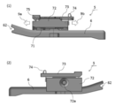
- FIG. 8 is a perspective view of the mitral valve model fixing jig of the first embodiment
- (1) is a perspective view from the front side
- (2) is a perspective view from the back side.
- 9 to 11 are external views of the mitral valve model fixing jig of the first embodiment
- FIG. 9 (1) is a front view
- FIG. 9 (2) is a rear view
- FIG. 10 (1) is a plan view
- 10 (2) is a bottom view
- FIG. 11 (1) is a left side view
- FIG. 11 (2) is a right side view.
- the mitral valve model fixing jig 5 includes a pedestal portion 6 and a fixing portion 7.
- the pedestal portion 6 includes a spine engagement mechanism for attaching the mitral valve model fixing jig 5 to the thoracic cavity simulator 8 described later. Specifically, the recess 61 shown in FIG. 10 (2), the concave engaging portion 62 shown in FIGS. 8 and 9, and the convex engaging portion 63 shown in FIG. 10 (2) are provided.
- the fixing portion 7 includes a mechanism for attaching and fixing the mitral valve model 1 and adjusting the fixing position. That is, as shown in FIG. 9 (1), the fixing portion 7 includes a support portion 71, a slide portion 72, and a clip portion 73. The support portion 71 and the slide portion 72 are slidably fixed by 25 mm in the directions indicated by the arrows (9a, 9b). A button 72a is provided on the slide portion 72, and the fixed state of the support portion 71 and the slide portion 72 can be released. That is, normally, the support portion 71 and the slide portion 72 are fixed, but by sliding the slide portion 72 while pressing the button 72a, the position of the slide portion 72 is in the direction indicated by the arrows (9a, 9b). It can be freely changed within a range of 25 mm. When the pressed state of the button 72a is released in the state where the position adjustment is completed, the support portion 71 and the slide portion 72 are fixed again.
- FIGS. 12A and 12B are external views of the mitral valve model fixing jig of the first embodiment with the stopper open
- FIG. 12 is a perspective view from the front side
- FIG. 12 is a perspective view from the back side.
- FIG. 13 shows a front view of the mitral valve model fixing jig of the first embodiment with the stopper open.
- the slide portion 72 and the clip portion 73 are connected via the hinge portion 75, and by operating the stopper 74, as shown by the arrows (9c, 9d), from the slide portion 72.
- the clip portion 73 can be opened and closed.
- FIGS. 12 (1) and 12 (2) the clip portion 73 is provided with a plate-shaped convex portion 73a so that the mitral valve model 1 can be attached.
- FIGS. 14A and 14B are external views of the mitral valve model when attached to the mitral valve model fixing jig, where (1) is a perspective view from the front side and (2) is a perspective view from the back side. There is. Further, FIG. 15 shows a front view of the mitral valve model when it is attached to the mitral valve model fixing jig. As shown in FIGS. 14 (1) and 14 (2), the through hole 42 of the mitral valve model 1 can be easily fitted into the convex portion 73a in the direction indicated by the arrow 9e with the clip portion 73 open. It can be attached.
- FIG. 16A and 16B are external views of the mitral valve model when fixed to the mitral valve model fixing jig, where (1) is a perspective view from the front side and (2) is a perspective view from the back side. There is. Further, FIG. 17 shows a front view of the mitral valve model when it is fixed to the mitral valve model fixing jig. As shown in FIG. 17, by closing the clip portion 73 and fastening the stopper 74 in the direction indicated by the arrow 9f, the lower portion of the through hole 42 of the mitral valve model 1 can be sandwiched between the clip portion 73 and the slide portion 72. Therefore, the mitral valve model 1 can be stably fixed. Further, as shown in FIG. 16 (1) or FIG.
- FIG. 18 shows an image of mounting the mitral valve model fixing jig to the thoracic cavity simulator.
- the thoracic cavity simulator 8 includes an upper end portion 81, a lower end portion 82, a sternum portion 83, a spine portion 84, and a rib portion 85.
- the thoracic cavity simulator 8 is in the supine position, but in the standing position, the upper end portion 81 is provided at the upper ends of the sternum portion 83 and the spine portion 84, and the lower end portion 82 is provided at the lower ends.
- the rib portion 85 is fixed to the sternum portion 83 and the spine portion 84.
- the lower end portion 82 is provided with a through hole 86 for attaching an organ model such as the mitral valve model 1.
- the thoracic cavity simulator 8 has a shape simulating the chest of the human body.
- FIG. 21 shows a flow chart of using the mitral valve model and the mitral valve model fixing jig.
- the stopper 74 of the mitral valve model fixing jig 5 is removed, and the clip portion 73 is opened (step S01).
- the through hole 42 provided in the mitral valve model 1 is fitted and attached to the convex portion 73a provided in the clip portion 73 (step S02).
- the clip portion 73 is closed, the stopper 74 is fastened, and the clip portion 73 and the slide portion 72 are fixed (step S03).
- FIG. 21 shows a flow chart of using the mitral valve model and the mitral valve model fixing jig.
- the mitral valve model fixing jig 5 to which the mitral valve model 1 is attached in the direction indicated by the arrow 9g from the through hole 86 provided in the lower end portion 82 of the thoracic cavity simulator 8. Is inserted, and the mitral valve model fixing jig 5 is attached to the spine portion 84 (step S04).
- a convex engaging portion (not shown) is provided on the upper end 81 side of the spine portion 84, and has a structure that engages with the concave engaging portion 62 provided on the pedestal portion 6.
- a concave engaging portion (not shown) is provided on the lower end 82 side of the spine portion 84, and has a structure that engages with the convex engaging portion 63 provided on the pedestal portion 6.
- FIG. 19 is an explanatory view when the mitral valve model fixing jig is attached to the thoracic cavity simulator, and shows a state in which the thoracic cavity simulator 8 is viewed from the right side.
- a space is formed between the ribs, such as the first intercostal space 85a, the second intercostal space 85b, the third intercostal space 85c, the fourth intercostal space 85d, or the fifth intercostal space 85e. ..
- an endoscope (not shown) is inserted from the 4th intercostal space 85d as shown by arrow 9h to perform surgery.
- FIG. 20 is an explanatory view of the slide mechanism of the mitral valve model fixing jig, (1) is a view of sliding the thoracic cavity simulator upward, and (2) is a view of sliding the thoracic cavity simulator downward. Shown. As shown in FIG. 20 (1), with the mitral valve model fixing jig 5 attached to the thoracic cavity simulator 8, the slide portion 72 is slid 25 mm in the direction of arrow 9a, that is, in the upward direction of the thoracic cavity simulator 8. .. Further, as shown in FIG.
- the slide portion 72 is slid 25 mm in the direction of arrow 9b, that is, in the downward direction of the thoracic cavity simulator 8. ing.
- the slide of the slide portion 72 is released from the fixed state of the support portion 71 and the slide portion 72 by pressing the button 72a, and the pressed state of the button 72a is released at an arbitrary position.
- the position of the mitral valve model 1 can be finely adjusted according to the sense of the operator.
- step S06 After adjusting the position of the mitral valve model 1, training is performed by inserting an instrument such as an endoscope through the intercostal space (step S06).
- the position of the mitral valve model 1 can be easily adjusted by inserting a hand from the through hole 86 provided in the lower end 82 of the thoracic cavity simulator 8 and operating the button 72a by the operator or an assistant. It is also possible to adjust the position during the procedure training.
- FIG. 22 shows a flow chart of mitral valve repair procedure training.
- the left atrial wall 2a is incised to secure the surgical field as shown in FIG. 5 (2) (step S11). Since the space inside the left atrium 2 is provided widely in advance, it is not necessary to further thread the left atrium wall 2a in an incised state to secure the surgical field.
- the portion of the posterior leaflet 3b that is in a deviant state is excised (step S12).
- the cut surface is stretched and sutured (step S13).
- an artificial chordae tendineae (not shown) is sewn to the papillary muscle and the valve leaflets (step S14).
- An artificial valve annulus (not shown) is sewn on the annulus wheel (step S15).
- the present invention is useful for training procedures such as mitral valve repair and mitral valve replacement. It is useful not only for complete endoscopic surgery using a surgery support robot, but also for surgical training of minimally invasive surgery such as MICS.
- Mitral valve model 2 Left ventricle 2a Left atrium wall 3 Mitral valve 3a Anterior leaflet 3b Posterior leaflet 3c Valve ring 4 Left ventricle 4a Left ventricle wall 5 Mitral valve model fixing jig 6 Pedestal 7 Fixing part 8 Thoracic cavity simulator 9a-9h Arrow 21 Left ventricle Ear 41a, 41b Papillary muscle 42,86 Through hole 61 Recessed 62 Concave engaging part 63 Convex engaging part 71 Support part 72 Slide part 72a Button 73 Clip part 73a Convex part 74 Stopper 75 Hing Part 76 Wall 81 Upper end 82 Lower end 83 Sternum 84 Backbone 85 Rib 85a 1st intercostal 85b 2nd intercostal 85c 3rd intercostal 85d 4th intercostal 85e 5th intercostal P spacing
Landscapes
- Engineering & Computer Science (AREA)
- Physics & Mathematics (AREA)
- General Physics & Mathematics (AREA)
- Health & Medical Sciences (AREA)
- Mathematical Analysis (AREA)
- Pure & Applied Mathematics (AREA)
- Medical Informatics (AREA)
- Algebra (AREA)
- Computational Mathematics (AREA)
- General Health & Medical Sciences (AREA)
- Chemical & Material Sciences (AREA)
- Mathematical Optimization (AREA)
- Mathematical Physics (AREA)
- Medicinal Chemistry (AREA)
- Business, Economics & Management (AREA)
- Educational Administration (AREA)
- Educational Technology (AREA)
- Theoretical Computer Science (AREA)
- Pulmonology (AREA)
- Radiology & Medical Imaging (AREA)
- Instructional Devices (AREA)
- Prostheses (AREA)
Abstract
Provided are a mitral valve model and a fixing jig which enable effective and low-cost training in mitral valvuloplasty or mitral valve replacement, and which can be easily handled and have a high level of convenience. This mitral valve model is for training of an endoscopic procedure in mitral valvuloplasty or mitral valve replacement, wherein the mitral valve model is obtained by reproducing or deforming the organ texture of the heart and comprises a left atrium part, a mitral valve part, and a left ventricle part, and the mitral valve part cannot be viewed from the outside and is covered by the left atrium part. The left atrium part and the left ventricle part are both hollow, and are preferably in at least any state among a state in which a valve cusp provided to the mitral valve part is deviated, a state in which the tendon that connects the valve cusp provided to the mitral valve part and the tip of the papillary muscle provided to the left ventricle part are ruptured, and a state in which the distance between the valve cusp provided to the mitral valve part and the tip of the papillary muscle is 3-7 mm.
Description
本発明は、僧帽弁形成術もしくは僧帽弁置換術のトレーニング用の臓器モデルに関するものである。
The present invention relates to an organ model for training mitral valve repair or mitral valve replacement.
一般に心臓疾患としては、狭心症や心筋梗塞などが知られている。心臓疾患の中でも、心臓弁膜症の患者は、推定患者数が200万人以上と非常に多く、年々増加しているといわれている。そして、心臓弁膜症の患者の内、年間約1万人の患者が手術を受けている。
心臓弁膜症の中でも、最も多いものの1つが僧帽弁閉鎖不全症である。僧帽弁閉鎖不全症とは、僧帽弁の閉鎖機能が悪くなり、左心室から大動脈に送られるはずの血液の一部が、左心房に逆流してしまう状態のことであり、僧帽弁逆流症ともいう。 Generally, angina pectoris and myocardial infarction are known as heart diseases. Among heart diseases, the estimated number of patients with valvular heart disease is as high as 2 million or more, and it is said that the number is increasing year by year. Of the patients with valvular heart disease, about 10,000 patients undergo surgery annually.
One of the most common valvular heart diseases is mitral regurgitation. Mitral regurgitation is a condition in which the mitral valve's closing function deteriorates and some of the blood that should be sent from the left ventricle to the aorta flows back into the left atrium. Also called reflux disease.
僧帽弁閉鎖不全症の原因としては、弁尖の逸脱、腱索の断裂、弁輪の拡大などが挙げられる。僧帽弁閉鎖不全症の治療方法としては、症状の緩和や進行を抑制する内科治療と、外科治療が存在する。外科治療は、弁を人工の弁に取り替える僧帽弁置換術と、患者自身の弁を修復することで逆流を制御する僧帽弁形成術が存在する。僧帽弁形成術は、患者自身の弁を修復するため、心臓の機能も温存されやすいという利点がある。また、弁の周辺での血液凝固がなく、僧帽弁置換術で機械弁を用いた場合のように抗凝固薬を一生内服する必要がないという利点もある。しかしながら、僧帽弁形成術は、僧帽弁置換術よりも難易度が高いという問題がある。
特に近年では、手術支援ロボットを用いた完全内視鏡下手術や、MICS(minimally invasive cardiac surgery)と呼ばれる小切開手術が多く行われている。これらの低侵襲手術は、胸を大きく切り開く胸骨正中切開手術よりも、患者の体への負担が少ないだけではなく、患者の体の右横から僧帽弁にアプローチできるため、閉鎖不全状態を観察しやすいという利点がある。しかしながら、これらの低侵襲手術は、医師に高度の技術力や経験が求められるため、医師が多数の経験を積み、技術力を向上させることが強く望まれる。 Causes of mitral regurgitation include deviation of the leaflet, rupture of the chordae tendineae, and enlargement of the annulus. Treatment methods for mitral regurgitation include medical treatment that relieves symptoms and suppresses progression, and surgical treatment. Surgical treatment includes mitral valve replacement, which replaces the valve with an artificial valve, and mitral valve repair, which controls regurgitation by repairing the patient's own valve. Mitral valve repair has the advantage that the function of the heart is easily preserved because it repairs the patient's own valve. In addition, there is no blood coagulation around the valve, and there is an advantage that it is not necessary to take an anticoagulant for a lifetime as in the case of using a mechanical valve in mitral valve replacement. However, mitral valve repair has the problem of being more difficult than mitral valve replacement.
In particular, in recent years, complete endoscopic surgery using a surgery support robot and small incision surgery called MICS (minimally invasive cardiac surgery) have been performed in many cases. These minimally invasive surgeries not only place less strain on the patient's body than median sternotomy, which opens the chest significantly, but also allow the mitral valve to be approached from the right side of the patient's body, observing insufficiency. It has the advantage of being easy to use. However, since these minimally invasive surgeries require doctors to have a high level of technical skill and experience, it is strongly desired that doctors gain a large amount of experience and improve their technical skills.
そこで近年、胸腔鏡下手術のトレーニングや学習用として、人の体型や質感を再現し、人の身体に対する手術環境を模擬できるシミュレータが開発されている(例えば、特許文献1を参照。)。
上記特許文献1に開示された胸腔シミュレータは、少なくとも肋骨を模擬した人体骨格モデルと、人体骨格モデルを収納するケーシングとから成る装置であり、ケーシングの肋骨部分に開孔部が設けられ、横隔膜の部分が開閉でき、人体骨格モデルの肋骨内部に臓器モデルを収納できる構成となっている。これによれば、患者の右胸部の肋骨の間から僧帽弁にアプローチする手技を効果的にトレーニングすることが可能である。 Therefore, in recent years, a simulator has been developed that can reproduce a human body shape and texture and simulate a surgical environment for a human body for training and learning of video-assisted thoracoscopic surgery (see, for example, Patent Document 1).
The thoracic cavity simulator disclosed inPatent Document 1 is a device including at least a human skeleton model simulating a rib and a casing for accommodating the human skeleton model, and an opening is provided in the rib portion of the casing to form a diaphragm. The part can be opened and closed, and the organ model can be stored inside the ribs of the human skeleton model. According to this, it is possible to effectively train the procedure of approaching the mitral valve from between the ribs of the patient's right chest.
上記特許文献1に開示された胸腔シミュレータは、少なくとも肋骨を模擬した人体骨格モデルと、人体骨格モデルを収納するケーシングとから成る装置であり、ケーシングの肋骨部分に開孔部が設けられ、横隔膜の部分が開閉でき、人体骨格モデルの肋骨内部に臓器モデルを収納できる構成となっている。これによれば、患者の右胸部の肋骨の間から僧帽弁にアプローチする手技を効果的にトレーニングすることが可能である。 Therefore, in recent years, a simulator has been developed that can reproduce a human body shape and texture and simulate a surgical environment for a human body for training and learning of video-assisted thoracoscopic surgery (see, for example, Patent Document 1).
The thoracic cavity simulator disclosed in
しかしながら、トレーニングに使用する人工の臓器モデルは、一般に製造コストが高いという問題がある。そこで、複数に分割可能な外型と中子を用い、液状樹脂を注入・硬化して製造を行う心臓模型が知られている(特許文献2を参照)。上記特許文献2に開示された心臓模型は、製造に使用する外型だけではなく中子についても、分割して再利用可能であるため、中子を粉砕等して廃棄する従来技術とは異なり、臓器モデルを低コストで大量生産できるとする。
しかしながら、上記特許文献2に開示された心臓模型は、実際の手術において特に必要ではない箇所についても正確に形状を再現しようとするため、十分にコストを低減できないという問題がある。 However, the artificial organ model used for training generally has a problem that the manufacturing cost is high. Therefore, there is known a heart model in which a liquid resin is injected and cured by using an outer mold and a core that can be divided into a plurality of parts (see Patent Document 2). The heart model disclosed inPatent Document 2 is different from the conventional technique in which the core is crushed and discarded because the core can be divided and reused not only for the outer mold used for manufacturing but also for the core. , Suppose that the organ model can be mass-produced at low cost.
However, the heart model disclosed inPatent Document 2 has a problem that the cost cannot be sufficiently reduced because it tries to accurately reproduce the shape even in a portion that is not particularly necessary in actual surgery.
しかしながら、上記特許文献2に開示された心臓模型は、実際の手術において特に必要ではない箇所についても正確に形状を再現しようとするため、十分にコストを低減できないという問題がある。 However, the artificial organ model used for training generally has a problem that the manufacturing cost is high. Therefore, there is known a heart model in which a liquid resin is injected and cured by using an outer mold and a core that can be divided into a plurality of parts (see Patent Document 2). The heart model disclosed in
However, the heart model disclosed in
また、上記特許文献1のシミュレータへの臓器モデルの取り付け方法としては、例えば、係合部が設けられた把持部材を用いるとしている。
一般に、患者の右胸部の肋骨の間から僧帽弁にアプローチする手技の場合、一般に第4肋間から内視鏡を挿し込んでアクセスするが、臓器モデルの取付位置が一箇所に固定され不変であると、術者によっては、当該アクセス位置から見た術野に違和感が生じることがある。しかしながら、上記特許文献1に開示された胸腔シミュレータでは、臓器モデルの取付位置を調整する器具や機構については十分に開示されていないという問題がある。 Further, as a method of attaching the organ model to the simulator ofPatent Document 1, for example, a gripping member provided with an engaging portion is used.
Generally, in the case of the procedure of approaching the mitral valve from between the ribs of the patient's right chest, the endoscope is generally inserted and accessed from the 4th intercostal space, but the mounting position of the organ model is fixed in one place and does not change. If there is, some surgeons may feel uncomfortable in the surgical field as seen from the access position. However, the thoracic cavity simulator disclosed inPatent Document 1 has a problem that the device and mechanism for adjusting the attachment position of the organ model are not sufficiently disclosed.
一般に、患者の右胸部の肋骨の間から僧帽弁にアプローチする手技の場合、一般に第4肋間から内視鏡を挿し込んでアクセスするが、臓器モデルの取付位置が一箇所に固定され不変であると、術者によっては、当該アクセス位置から見た術野に違和感が生じることがある。しかしながら、上記特許文献1に開示された胸腔シミュレータでは、臓器モデルの取付位置を調整する器具や機構については十分に開示されていないという問題がある。 Further, as a method of attaching the organ model to the simulator of
Generally, in the case of the procedure of approaching the mitral valve from between the ribs of the patient's right chest, the endoscope is generally inserted and accessed from the 4th intercostal space, but the mounting position of the organ model is fixed in one place and does not change. If there is, some surgeons may feel uncomfortable in the surgical field as seen from the access position. However, the thoracic cavity simulator disclosed in
かかる状況に鑑みて、本発明は、僧帽弁形成術もしくは僧帽弁置換術について、効果的かつ低コストでのトレーニングを可能とし、さらに取扱いが容易で利便性の高い僧帽弁モデル及び固定治具を提供することを目的とする。
In view of this situation, the present invention enables effective and low-cost training for mitral valve repair or mitral valve replacement, and is an easy-to-use and convenient mitral valve model and fixation. It is an object of the present invention to provide a jig.
上記課題を解決すべく、本発明の僧帽弁モデルは、僧帽弁形成術もしくは僧帽弁置換術の内視鏡下手技のトレーニング用の僧帽弁モデルであって、僧帽弁モデルは、心臓の臓器の質感を再現又はデフォルメしたもので、左心房部、僧帽弁部、左心室部から成り、僧帽弁部が外部から視認できず、左心房部に覆われている。
僧帽弁部が外部から視認できず、左心房部に覆われていることにより、左心房部の左心房壁を切開した上で、弁尖の切除等を行うことができ、よりリアルな手技トレーニングが可能となる。 In order to solve the above problems, the mitral valve model of the present invention is a mitral valve model for training endoscopic procedures of mitral valve plasty or mitral valve replacement, and the mitral valve model is , The texture of the organs of the heart is reproduced or deformed. It consists of the left atrium, the mitral valve, and the left ventricle. The mitral valve is invisible from the outside and is covered by the left atrium.
Since the mitral valve is not visible from the outside and is covered by the left atrium, the left atrium wall of the left atrium can be incised and the valve leaflets can be excised, which is a more realistic procedure. Training becomes possible.
本発明の僧帽弁モデルにおいて、左心房部と左心室部は、共に中空で、下記1)~3)の少なくとも何れかの状態とされることが好ましい。
1)僧帽弁部に設けられた弁尖が逸脱状態。
2)僧帽弁部に設けられた弁尖と左心室部に設けられた乳頭筋の先端とを繋ぐ腱索が断裂状態。
3)僧帽弁部に設けられた弁尖と乳頭筋の先端との距離が3~7mm。 In the mitral valve model of the present invention, the left atrium and the left ventricle are both hollow, and it is preferable that at least one of the following 1) to 3) is set.
1) The leaflet provided on the mitral valve is in a deviant state.
2) The chordae tendineae connecting the leaflet provided in the mitral valve and the tip of the papillary muscle provided in the left ventricle are in a ruptured state.
3) The distance between the leaflet provided on the mitral valve and the tip of the papillary muscle is 3 to 7 mm.
上記1)について、逸脱状態は、前尖に設けられていてもよいし、後尖に設けられていてもよい。また、逸脱状態とは、狭義の意味での逸脱だけではなく、弁尖の肥大も含まれる意味で用いている。上記2)については、腱索の断裂状態をよりリアルに再現するために、乳頭筋の先端は丸く形成されることが好ましい。上記3)の弁尖と乳頭筋の先端とのより好ましい距離は5mmである。
Regarding 1) above, the deviation state may be provided on the anterior leaflet or the posterior leaflet. In addition, the deviant state is used to include not only deviation in a narrow sense but also hypertrophy of the valve leaflets. Regarding 2) above, it is preferable that the tip of the papillary muscle is formed round in order to more realistically reproduce the torn state of the chordae tendineae. The more preferable distance between the valve leaflet and the tip of the papillary muscle in 3) above is 5 mm.
本発明の僧帽弁モデルにおいて、左心房部の表層は、心臓の臓器の硬度及び厚みを再現又はデフォルメしたもので、手技で用いる器具によって把持及び切開し得ることが好ましい。
僧帽弁形成術もしくは僧帽弁置換術の手技トレーニングを行うに当たっては、左心房壁を切開する必要があるため、硬度及び厚みを再現することで、臓器の把持や切開といったトレーニングをよりリアルに行うことができる。また、把持や切開などの手技と関連性の低い箇所については硬度又は厚みをデフォルメすることで、低コストでの作製が可能となる。 In the mitral valve model of the present invention, the surface layer of the left atrium preferably reproduces or deforms the hardness and thickness of the heart organ, and can be grasped and incised by an instrument used in the procedure.
Since it is necessary to make an incision in the left atrium wall when performing mitral valve repair or mitral valve replacement procedure training, by reproducing the hardness and thickness, training such as organ grasping and incision becomes more realistic. It can be carried out. In addition, by deforming the hardness or thickness of the parts that are not related to the procedure such as grasping and incision, it is possible to manufacture at low cost.
本発明の僧帽弁モデルにおいて、左心房部の形状は、現実の内視鏡下手技におけるスコープ映像に基づきデフォルメされた略球欠形状であることが好ましい。左心房部の形状を厳密に再現するのではなく、左心房部の形状を大胆にデフォルメすることで、内視鏡で見た際のスコープ映像をより実際の手術映像に近いものとすることができる。
In the mitral valve model of the present invention, the shape of the left atrium is preferably a substantially spherical shape that is deformed based on the scope image in the actual endoscopic procedure. By boldly deforming the shape of the left atrium rather than exactly reproducing the shape of the left atrium, it is possible to make the scope image when viewed with an endoscope closer to the actual surgical image. it can.
本発明の僧帽弁モデルにおいて、質感の再現としては、左心房部を構成する素材に微細気泡が含まれることが好ましい。微細気泡が含まれることにより、鉗子等で把持した際に滑りにくく、また、柔軟性が高くなり把持しやすくなる。また、僧帽弁部は、病変を切除した後に、切離面を引き延ばして縫合する手技を行うため、強度を高めるべく繊維が含まれる素材としてもよい。
In the mitral valve model of the present invention, it is preferable that the material constituting the left atrium contains fine bubbles in order to reproduce the texture. Due to the inclusion of fine bubbles, it is difficult to slip when gripped with forceps or the like, and the flexibility is increased to facilitate gripping. Further, since the mitral valve portion is subjected to a procedure of stretching and suturing the incised surface after excising the lesion, the mitral valve portion may be a material containing fibers in order to increase the strength.
本発明の僧帽弁モデルにおいて、質感のデフォルメとしては、左心室部を構成する素材に微細気泡及び繊維が含まれないことでもよい。把持や切開などの手技と関連性の低い箇所については微細気泡や繊維が含まれない構成とすることで、低コストでの作製が可能となる。
In the mitral valve model of the present invention, as the texture deformation, the material constituting the left ventricle may not contain fine bubbles and fibers. For parts that are not closely related to procedures such as grasping and incision, it is possible to manufacture at low cost by making the structure free of fine bubbles and fibers.
本発明の僧帽弁モデルにおいて、左心室部の下側に、胸腔シミュレータに臓器を固定するための固定治具に取付けるための取付機構が設けられたことが好ましい。僧帽弁モデル自体に取付機構が設けられることにより、固定治具への取り付けが容易となり、利便性が向上する。取付機構の例としては、貫通孔、凹部又は凸部などが挙げられる。
In the mitral valve model of the present invention, it is preferable that a mounting mechanism for mounting on a fixing jig for fixing an organ to the thoracic cavity simulator is provided below the left ventricle. By providing the mounting mechanism on the mitral valve model itself, it becomes easy to mount it on the fixing jig and the convenience is improved. Examples of the mounting mechanism include through holes, concave portions, convex portions, and the like.
本発明の僧帽弁モデル固定治具は、上記の僧帽弁モデルを取り付け、固定するための固定治具であって、固定治具は、胸腔シミュレータの内部の背骨部位に係着するための係着機構を備えた台座部と、僧帽弁モデルを固定するための固定部を備え、固定部は、僧帽弁モデルを取り付け固定した状態で、台座部を背骨部位上にスライドさせて固定させた位置から、背骨部位の長手方向にスライドさせて更に位置を微調整し得る機構を備える。
胸腔シミュレータの内部の背骨部位に係着するための係着機構としては、凸型又は凹型の係合部で、胸腔シミュレータの内部の背骨部位に設けられた、凹型又は凸型の係合部と係合することが好ましい。
僧帽弁モデルの固定については、僧帽弁モデルに設けられた取付機構を利用して取り付け、かつ、トレーニング中に固定治具から僧帽弁モデルが脱落することのないように固定し得る機構を備えることが好ましい。 The mitral valve model fixing jig of the present invention is a fixing jig for attaching and fixing the above-mentioned mitral valve model, and the fixing jig is for engaging with the spine portion inside the thoracic cavity simulator. It has a pedestal part with an engagement mechanism and a fixing part for fixing the mitral valve model, and the fixing part is fixed by sliding the pedestal part onto the spine part with the mitral valve model attached and fixed. It is provided with a mechanism capable of further fine-tuning the position by sliding it in the longitudinal direction of the spine portion from the moved position.
The engagement mechanism for engaging with the spine part inside the thoracic cavity simulator is a convex or concave engaging part, and the concave or convex engaging part provided at the spine part inside the thoracic cavity simulator. It is preferable to engage.
Regarding the fixing of the mitral valve model, a mechanism that can be attached using the attachment mechanism provided in the mitral valve model and can be fixed so that the mitral valve model does not fall off from the fixing jig during training. It is preferable to provide.
本発明の僧帽弁モデル固定治具において、固定部は、僧帽弁モデルの左心房部の正面の外向き方向を、背骨部位の長手方向であって頭部へ向かう方向と、その直交方向であって胸腔シミュレータの中心から右手側の方向との間で、微調整し得る回転テーブル機構を備える。
実際に患者の右横からアプローチして、僧帽弁形成術もしくは僧帽弁置換術を行う際には、内視鏡で僧帽弁が見えるように、患者の心臓の位置や向きを変えて手術を行う。そのため、患者の頭部側から右側までの90°の範囲内で、僧帽弁モデルの向きを微調整し得る回転テーブル機構を備えることにより、より実際の手術に近い術野が得られることになる。 In the mitral valve model fixing jig of the present invention, the fixing portion has the outward direction of the front surface of the left atrium of the mitral valve model, the longitudinal direction of the spine portion and the direction toward the head, and the direction orthogonal to the direction It is equipped with a rotary table mechanism that can be finely adjusted from the center of the thoracic cavity simulator to the direction on the right hand side.
When actually approaching from the right side of the patient and performing mitral valve repair or mitral valve replacement, change the position and orientation of the patient's heart so that the mitral valve can be seen with an endoscope. Perform surgery. Therefore, by providing a rotary table mechanism that can finely adjust the orientation of the mitral valve model within a range of 90 ° from the patient's head side to the right side, a surgical field closer to the actual surgery can be obtained. Become.
本発明の僧帽弁モデル及び固定治具によれば、僧帽弁形成術もしくは僧帽弁置換術について、効果的かつ低コストでのトレーニングが可能となり、さらに取扱いが容易で利便性の高い僧帽弁モデル及び固定治具として利用できるといった効果がある。
According to the mitral valve model and the fixing jig of the present invention, effective and low-cost training for mitral valve plasty or mitral valve replacement is possible, and the mitral valve is easier to handle and more convenient. It has the effect of being able to be used as a cap valve model and a fixing jig.
以下、本発明の実施形態の一例を、図面を参照しながら詳細に説明していく。なお、本発明の範囲は、以下の実施例や図示例に限定されるものではなく、幾多の変更及び変形が可能である。
Hereinafter, an example of the embodiment of the present invention will be described in detail with reference to the drawings. The scope of the present invention is not limited to the following examples and illustrated examples, and many modifications and modifications can be made.
図1は、実施例1の僧帽弁モデルの斜視図を示している。また、図2~4は、実施例1の僧帽弁モデルの外観図であり、図2(1)は正面図、図2(2)は背面図、図3(1)は平面図、図3(2)は底面図、図4(1)は左側面図、図4(2)は右側面図を示している。
図1に示すように、僧帽弁モデル1は、左心房部2、僧帽弁部3及び左心室部4から成る。僧帽弁モデル1は、患者に人工心肺のポンプを付け、心臓から血液を抜き、さらに内視鏡下の手技でガスを入れて圧力をかけた状態で、心臓が扁平した形を再現又はデフォルメしたものであり、特に内視鏡のスコープから見た際の形状をリアルに再現している。左心房部2、僧帽弁部3及び左心室部4は、それぞれ別々に成形された後、接着されて僧帽弁モデル1となっているが、一体成形されたことでもよい。 FIG. 1 shows a perspective view of the mitral valve model of Example 1. 2 to 4 are external views of the mitral valve model of the first embodiment, FIG. 2 (1) is a front view, FIG. 2 (2) is a rear view, and FIG. 3 (1) is a plan view. 3 (2) is a bottom view, FIG. 4 (1) is a left side view, and FIG. 4 (2) is a right side view.
As shown in FIG. 1, themitral valve model 1 comprises a left atrium 2, a mitral valve 3, and a left ventricle 4. The mitral valve model 1 reproduces or deforms the flattened shape of the heart in a state where the patient is equipped with an artificial heart-lung machine pump, blood is drawn from the heart, and gas is added and pressure is applied by an endoscopic procedure. It is a realistic reproduction of the shape seen from the scope of the endoscope. The left atrium 2, the mitral valve 3, and the left ventricle 4 are molded separately and then adhered to form the mitral valve model 1, but may be integrally molded.
図1に示すように、僧帽弁モデル1は、左心房部2、僧帽弁部3及び左心室部4から成る。僧帽弁モデル1は、患者に人工心肺のポンプを付け、心臓から血液を抜き、さらに内視鏡下の手技でガスを入れて圧力をかけた状態で、心臓が扁平した形を再現又はデフォルメしたものであり、特に内視鏡のスコープから見た際の形状をリアルに再現している。左心房部2、僧帽弁部3及び左心室部4は、それぞれ別々に成形された後、接着されて僧帽弁モデル1となっているが、一体成形されたことでもよい。 FIG. 1 shows a perspective view of the mitral valve model of Example 1. 2 to 4 are external views of the mitral valve model of the first embodiment, FIG. 2 (1) is a front view, FIG. 2 (2) is a rear view, and FIG. 3 (1) is a plan view. 3 (2) is a bottom view, FIG. 4 (1) is a left side view, and FIG. 4 (2) is a right side view.
As shown in FIG. 1, the
左心房部2の外観は、図2(1)に示すように、正面視では角丸の逆三角形を基により丸みを帯びた形状となっており、実質的には略円形状を呈している。また、図1~4に示すように、全体形状としては略球欠形状となっており、僧帽弁部2と接続されている。図4(1)に示すように、左心房部2には、左心耳21が設けられている。一般的に、僧帽弁形成術等の心臓手術の際には、血栓塞栓症のリスクを下げるために左心耳閉鎖術も同時に行う。そこで、左心耳21が設けられることにより、同時に左心耳閉鎖術の手技トレーニングを行うことも可能な構成となっている。
As shown in FIG. 2 (1), the appearance of the left atrium 2 has a rounded shape based on an inverted triangle with rounded corners when viewed from the front, and is substantially circular in shape. .. Further, as shown in FIGS. 1 to 4, the overall shape is a substantially spherical shape, and is connected to the mitral valve portion 2. As shown in FIG. 4 (1), the left atrial region 2 is provided with a left atrial appendage 21. Generally, at the time of heart surgery such as mitral valve repair, left atrial appendage occlusion is also performed at the same time to reduce the risk of thromboembolism. Therefore, by providing the left atrial appendage 21, it is possible to perform the procedure training of the left atrial appendage occlusion at the same time.
左心室部4の外観は、図2(2)、図3又は図4に示すように、略直方体形状を呈しており、僧帽弁部2と接続されている。左心室部4の上端部は、図2(2)に示すように、角丸に形成されており、後述するが、左心室壁が再現されている。左心室部4の下部には、貫通孔42が形成されており、後述する僧帽弁固定治具5に容易に取り付けることが可能である。また、僧帽弁モデル1の僧帽弁固定治具5への取り付けを容易にするために、左心室部4の下端部は、図2又は図4に示すように、平坦な形状とされている。
僧帽弁部3は、外観上は見えず、左心房部2に覆われている。したがって、トレーニングにおいて左心房部2を切開することで僧帽弁部3が現れるため、よりリアルなトレーニングが可能である。 The appearance of theleft ventricular portion 4 has a substantially rectangular parallelepiped shape as shown in FIG. 2 (2), FIG. 3 or FIG. 4, and is connected to the mitral valve portion 2. As shown in FIG. 2 (2), the upper end of the left ventricular portion 4 is formed with rounded corners, and as will be described later, the left ventricular wall is reproduced. A through hole 42 is formed in the lower part of the left ventricular portion 4, and can be easily attached to the mitral valve fixing jig 5 described later. Further, in order to facilitate attachment of the mitral valve model 1 to the mitral valve fixing jig 5, the lower end portion of the left ventricular portion 4 has a flat shape as shown in FIG. 2 or FIG. There is.
Themitral valve portion 3 is not visible in appearance and is covered with the left atrium portion 2. Therefore, since the mitral valve portion 3 appears by incising the left atrium portion 2 in the training, more realistic training is possible.
僧帽弁部3は、外観上は見えず、左心房部2に覆われている。したがって、トレーニングにおいて左心房部2を切開することで僧帽弁部3が現れるため、よりリアルなトレーニングが可能である。 The appearance of the
The
次に、僧帽弁モデル1の内部構造について説明する。図5(1)は僧帽弁モデルの左側面図であり、図5(2)は、図5(1)におけるA-A断面図を示している。図5(2)に示すように、左心房部2は、左心房壁2aで形成され、正面視で左下の位置には左心耳21が設けられている。僧帽弁部3は、前尖3a、後尖3b及び弁輪3cから成り、左心房部2は、弁輪3cの位置において僧帽弁部3と接続されている。僧帽弁部3は、正常な人体における僧帽弁を再現したものではなく、弁尖の内、後尖3bの中央が逸脱状態となっており、僧帽弁閉鎖不全症の病変の一例が再現されている。ここでは後尖3bの中央が逸脱状態となっているが、病変はかかる位置に限定されず、例えば、前尖3aが逸脱状態となったものでもよいし、後尖3bの左右が逸脱状態となったものでもよい。病変の位置を変えることで、多様なバリエーションのトレーニングが可能となる。
Next, the internal structure of the mitral valve model 1 will be described. FIG. 5 (1) is a left side view of the mitral valve model, and FIG. 5 (2) shows a cross-sectional view taken along the line AA in FIG. 5 (1). As shown in FIG. 5 (2), the left atrium portion 2 is formed by the left atrium wall 2a, and the left atrial appendage 21 is provided at the lower left position in the front view. The mitral valve portion 3 is composed of an anterior leaflet 3a, a posterior leaflet 3b and an annulus 3c, and the left atrium 2 is connected to the mitral valve annulus 3 at the position of the annulus 3c. The mitral valve part 3 does not reproduce the mitral valve in a normal human body, and the center of the posterior leaflet 3b of the valve leaflets is in a deviant state, and an example of a lesion of mitral regurgitation is It has been reproduced. Here, the center of the posterior leaflet 3b is in a deviant state, but the lesion is not limited to such a position. For example, the anterior leaflet 3a may be in a deviant state, or the left and right sides of the posterior leaflet 3b are in a deviant state. It may be a lesion. By changing the position of the lesion, various variations of training become possible.
図6(1)は僧帽弁モデルの左側面図であり、図6(2)は、図6(1)におけるB-B断面図を示している。また、図7(1)は僧帽弁モデルの正面図であり、図7(2)は、図7(1)におけるC-C断面図を示している。
図6(2)又は図7(2)に示すように、左心室部4は左心室壁4aで周囲を覆われ、内部は中空となっており、乳頭筋(41a,41b)が設けられている。乳頭筋(41a,41b)の先端には腱索は設けられておらず、腱索が断裂した状態が再現されている。図7(2)に示す僧帽弁部3と乳頭筋41aの間隔Pは、5mmとなっている。かかる距離は、実際に手術を行う際の僧帽弁と乳頭筋の距離をリアルに再現したものである。また、乳頭筋(41a,41b)の先端は、丸く形成されており、かかる点でも実際の乳頭筋の形状がリアルに再現されている。
図7(2)に示すように、左心房部2の内部空間は広く設けられており、手技トレーニングにおいて、左心房壁2aを切開した後に、弁輪3cに糸かけが行われた状態と同じ状態を再現可能としている。 FIG. 6 (1) is a left side view of the mitral valve model, and FIG. 6 (2) shows a sectional view taken along line BB in FIG. 6 (1). Further, FIG. 7 (1) is a front view of the mitral valve model, and FIG. 7 (2) shows a sectional view taken along line CC in FIG. 7 (1).
As shown in FIG. 6 (2) or FIG. 7 (2), theleft ventricular portion 4 is surrounded by the left ventricular wall 4a, the inside is hollow, and the papillary muscles (41a, 41b) are provided. There is. No chordae tendineae are provided at the tips of the papillary muscles (41a, 41b), and the state in which the chordae tendineae are torn is reproduced. The distance P between the mitral valve portion 3 and the papillary muscle 41a shown in FIG. 7 (2) is 5 mm. This distance is a realistic reproduction of the distance between the mitral valve and the papillary muscle during actual surgery. Further, the tips of the papillary muscles (41a, 41b) are formed to be round, and the actual shape of the papillary muscles is realistically reproduced in this respect as well.
As shown in FIG. 7 (2), the internal space of theleft atrium 2 is widely provided, which is the same as the state in which the annulus 3c is threaded after the left atrium wall 2a is incised in the procedure training. The state can be reproduced.
図6(2)又は図7(2)に示すように、左心室部4は左心室壁4aで周囲を覆われ、内部は中空となっており、乳頭筋(41a,41b)が設けられている。乳頭筋(41a,41b)の先端には腱索は設けられておらず、腱索が断裂した状態が再現されている。図7(2)に示す僧帽弁部3と乳頭筋41aの間隔Pは、5mmとなっている。かかる距離は、実際に手術を行う際の僧帽弁と乳頭筋の距離をリアルに再現したものである。また、乳頭筋(41a,41b)の先端は、丸く形成されており、かかる点でも実際の乳頭筋の形状がリアルに再現されている。
図7(2)に示すように、左心房部2の内部空間は広く設けられており、手技トレーニングにおいて、左心房壁2aを切開した後に、弁輪3cに糸かけが行われた状態と同じ状態を再現可能としている。 FIG. 6 (1) is a left side view of the mitral valve model, and FIG. 6 (2) shows a sectional view taken along line BB in FIG. 6 (1). Further, FIG. 7 (1) is a front view of the mitral valve model, and FIG. 7 (2) shows a sectional view taken along line CC in FIG. 7 (1).
As shown in FIG. 6 (2) or FIG. 7 (2), the
As shown in FIG. 7 (2), the internal space of the
ここで、僧帽弁モデル1の材質について説明する。まず、左心房部2は、僧帽弁形成術等を行うために、左心房壁2aを切開する必要があるため、鉗子等で左心房壁2aを摘んだ際の質感が、実際の左心房壁と同様である必要がある。また、僧帽弁部3は、僧帽弁形成術において、弁尖を切離した後に、切離面を引き延ばして縫合する必要があるため、縫合に耐え得る素材である必要がある。
したがって、左心室部4については、左心室壁4aを含む左心室部全体がポリビニルアルコール樹脂で形成されているが、左心房部2の左心房壁2aは、ポリビニルアルコール樹脂に微細気泡(図示せず)が含まれた材質で形成されている。そのため、左心房壁2aの材質は、左心室壁4aの材質よりも滑り難く、かつ柔軟性が高いため鉗子で摘み易く、実際の左心房壁に類似した質感となっている。
また、僧帽弁部3は、左心室壁4a及び左心房壁2aとは異なり、ポリビニルアルコール樹脂に繊維が含まれた材質で形成され、切離面を引き延ばして縫合することが可能な強度となっている。なお、僧帽弁モデル1の材質としては、ポリビニルアルコール樹脂に限られず、柔軟性、伸縮性等を備えたその他の樹脂素材を用いてもよい。 Here, the material of themitral valve model 1 will be described. First, since the left atrium 2 needs to make an incision in the left atrium wall 2a in order to perform mitral valve repair or the like, the texture when the left atrium wall 2a is picked up with a forceps or the like is the actual left atrium. Must be similar to a wall. Further, in the mitral valve plasty, the mitral valve portion 3 needs to be made of a material that can withstand suturing because it is necessary to stretch and suture the cut surface after the leaflet is cut off.
Therefore, with respect to theleft ventricle portion 4, the entire left ventricle portion including the left ventricle wall 4a is formed of the polyvinyl alcohol resin, but the left atrium wall 2a of the left atrium portion 2 has fine bubbles (shown) in the polyvinyl alcohol resin. It is made of a material that contains. Therefore, the material of the left atrium wall 2a is less slippery than the material of the left ventricle wall 4a and is more flexible, so that it is easy to pick up with forceps and has a texture similar to that of the actual left atrium wall.
Further, unlike theleft ventricular wall 4a and the left atrium wall 2a, the mitral valve portion 3 is made of a material containing fibers in polyvinyl alcohol resin, and has a strength capable of stretching and suturing the cut surface. It has become. The material of the mitral valve model 1 is not limited to the polyvinyl alcohol resin, and other resin materials having flexibility, elasticity, and the like may be used.
したがって、左心室部4については、左心室壁4aを含む左心室部全体がポリビニルアルコール樹脂で形成されているが、左心房部2の左心房壁2aは、ポリビニルアルコール樹脂に微細気泡(図示せず)が含まれた材質で形成されている。そのため、左心房壁2aの材質は、左心室壁4aの材質よりも滑り難く、かつ柔軟性が高いため鉗子で摘み易く、実際の左心房壁に類似した質感となっている。
また、僧帽弁部3は、左心室壁4a及び左心房壁2aとは異なり、ポリビニルアルコール樹脂に繊維が含まれた材質で形成され、切離面を引き延ばして縫合することが可能な強度となっている。なお、僧帽弁モデル1の材質としては、ポリビニルアルコール樹脂に限られず、柔軟性、伸縮性等を備えたその他の樹脂素材を用いてもよい。 Here, the material of the
Therefore, with respect to the
Further, unlike the
次に、実施例1の僧帽弁モデル固定治具の構造について説明する。図8は、実施例1の僧帽弁モデル固定治具の斜視図であり、(1)は正面側からの斜視図、(2)は背面側からの斜視図を示している。また、図9~11は、実施例1の僧帽弁モデル固定治具の外観図であり、図9(1)は正面図、図9(2)は背面図、図10(1)は平面図、図10(2)は底面図、図11(1)は左側面図、図11(2)は右側面図を示している。
図8(1)及び(2)に示すように僧帽弁モデル固定治具5は、台座部6及び固定部7から成る。台座部6は、後述する胸腔シミュレータ8に僧帽弁モデル固定治具5を取り付けるための背骨係着機構を備える。具体的には、図10(2)に示す凹部61、図8及び図9に示す凹型係合部62、及び図10(2)に示す凸型係合部63が設けられている。 Next, the structure of the mitral valve model fixing jig of Example 1 will be described. FIG. 8 is a perspective view of the mitral valve model fixing jig of the first embodiment, (1) is a perspective view from the front side, and (2) is a perspective view from the back side. 9 to 11 are external views of the mitral valve model fixing jig of the first embodiment, FIG. 9 (1) is a front view, FIG. 9 (2) is a rear view, and FIG. 10 (1) is a plan view. 10 (2) is a bottom view, FIG. 11 (1) is a left side view, and FIG. 11 (2) is a right side view.
As shown in FIGS. 8 (1) and 8 (2), the mitral valvemodel fixing jig 5 includes a pedestal portion 6 and a fixing portion 7. The pedestal portion 6 includes a spine engagement mechanism for attaching the mitral valve model fixing jig 5 to the thoracic cavity simulator 8 described later. Specifically, the recess 61 shown in FIG. 10 (2), the concave engaging portion 62 shown in FIGS. 8 and 9, and the convex engaging portion 63 shown in FIG. 10 (2) are provided.
図8(1)及び(2)に示すように僧帽弁モデル固定治具5は、台座部6及び固定部7から成る。台座部6は、後述する胸腔シミュレータ8に僧帽弁モデル固定治具5を取り付けるための背骨係着機構を備える。具体的には、図10(2)に示す凹部61、図8及び図9に示す凹型係合部62、及び図10(2)に示す凸型係合部63が設けられている。 Next, the structure of the mitral valve model fixing jig of Example 1 will be described. FIG. 8 is a perspective view of the mitral valve model fixing jig of the first embodiment, (1) is a perspective view from the front side, and (2) is a perspective view from the back side. 9 to 11 are external views of the mitral valve model fixing jig of the first embodiment, FIG. 9 (1) is a front view, FIG. 9 (2) is a rear view, and FIG. 10 (1) is a plan view. 10 (2) is a bottom view, FIG. 11 (1) is a left side view, and FIG. 11 (2) is a right side view.
As shown in FIGS. 8 (1) and 8 (2), the mitral valve
固定部7は、僧帽弁モデル1を取り付け、固定し、かつ固定位置を調整する機構を備える。すなわち、固定部7は、図9(1)に示すように、支持部71、スライド部72及びクリップ部73から成る。
支持部71とスライド部72は、矢印(9a,9b)に示す方向に25mmずつ摺動自在に固定されている。スライド部72には、ボタン72aが設けられており、支持部71とスライド部72の固定状態を解除することが可能である。すなわち、通常は支持部71とスライド部72は固定されているが、ボタン72aを押下しながら、スライド部72をスライドさせることで、スライド部72の位置を矢印(9a,9b)に示す方向に25mmずつの範囲で自在に変化させることができる。位置調整が完了した状態で、ボタン72aの押下状態を解除すると、支持部71とスライド部72は再度固定される。 The fixingportion 7 includes a mechanism for attaching and fixing the mitral valve model 1 and adjusting the fixing position. That is, as shown in FIG. 9 (1), the fixing portion 7 includes a support portion 71, a slide portion 72, and a clip portion 73.
Thesupport portion 71 and the slide portion 72 are slidably fixed by 25 mm in the directions indicated by the arrows (9a, 9b). A button 72a is provided on the slide portion 72, and the fixed state of the support portion 71 and the slide portion 72 can be released. That is, normally, the support portion 71 and the slide portion 72 are fixed, but by sliding the slide portion 72 while pressing the button 72a, the position of the slide portion 72 is in the direction indicated by the arrows (9a, 9b). It can be freely changed within a range of 25 mm. When the pressed state of the button 72a is released in the state where the position adjustment is completed, the support portion 71 and the slide portion 72 are fixed again.
支持部71とスライド部72は、矢印(9a,9b)に示す方向に25mmずつ摺動自在に固定されている。スライド部72には、ボタン72aが設けられており、支持部71とスライド部72の固定状態を解除することが可能である。すなわち、通常は支持部71とスライド部72は固定されているが、ボタン72aを押下しながら、スライド部72をスライドさせることで、スライド部72の位置を矢印(9a,9b)に示す方向に25mmずつの範囲で自在に変化させることができる。位置調整が完了した状態で、ボタン72aの押下状態を解除すると、支持部71とスライド部72は再度固定される。 The fixing
The
図12は、実施例1の僧帽弁モデル固定治具のストッパー開状態の外観図であり、(1)は正面側からの斜視図、(2)は背面側からの斜視図を示している。また、図13は、実施例1の僧帽弁モデル固定治具のストッパー開状態の正面図を示している。
図13に示すように、スライド部72とクリップ部73は、ヒンジ部75を介して接続されており、ストッパー74を操作することで、矢印(9c,9d)に示すように、スライド部72からクリップ部73を開閉可能である。また、図12(1)及び(2)に示すように、クリップ部73にはプレート状の凸部73aが設けられており、僧帽弁モデル1を取り付けることが可能な構造となっている。 12A and 12B are external views of the mitral valve model fixing jig of the first embodiment with the stopper open, FIG. 12 is a perspective view from the front side, and FIG. 12 is a perspective view from the back side. .. Further, FIG. 13 shows a front view of the mitral valve model fixing jig of the first embodiment with the stopper open.
As shown in FIG. 13, theslide portion 72 and the clip portion 73 are connected via the hinge portion 75, and by operating the stopper 74, as shown by the arrows (9c, 9d), from the slide portion 72. The clip portion 73 can be opened and closed. Further, as shown in FIGS. 12 (1) and 12 (2), the clip portion 73 is provided with a plate-shaped convex portion 73a so that the mitral valve model 1 can be attached.
図13に示すように、スライド部72とクリップ部73は、ヒンジ部75を介して接続されており、ストッパー74を操作することで、矢印(9c,9d)に示すように、スライド部72からクリップ部73を開閉可能である。また、図12(1)及び(2)に示すように、クリップ部73にはプレート状の凸部73aが設けられており、僧帽弁モデル1を取り付けることが可能な構造となっている。 12A and 12B are external views of the mitral valve model fixing jig of the first embodiment with the stopper open, FIG. 12 is a perspective view from the front side, and FIG. 12 is a perspective view from the back side. .. Further, FIG. 13 shows a front view of the mitral valve model fixing jig of the first embodiment with the stopper open.
As shown in FIG. 13, the
図14は、僧帽弁モデルの僧帽弁モデル固定治具への取付時の外観図であり、(1)は正面側からの斜視図、(2)は背面側からの斜視図を示している。また、図15は、僧帽弁モデルの僧帽弁モデル固定治具への取付時の正面図を示している。
図14(1)及び(2)に示すように、クリップ部73を開いた状態で、矢印9eに示す方向に、僧帽弁モデル1の貫通孔42を凸部73aに嵌め込むことにより簡単に取り付けることが可能である。 14A and 14B are external views of the mitral valve model when attached to the mitral valve model fixing jig, where (1) is a perspective view from the front side and (2) is a perspective view from the back side. There is. Further, FIG. 15 shows a front view of the mitral valve model when it is attached to the mitral valve model fixing jig.
As shown in FIGS. 14 (1) and 14 (2), the throughhole 42 of the mitral valve model 1 can be easily fitted into the convex portion 73a in the direction indicated by the arrow 9e with the clip portion 73 open. It can be attached.
図14(1)及び(2)に示すように、クリップ部73を開いた状態で、矢印9eに示す方向に、僧帽弁モデル1の貫通孔42を凸部73aに嵌め込むことにより簡単に取り付けることが可能である。 14A and 14B are external views of the mitral valve model when attached to the mitral valve model fixing jig, where (1) is a perspective view from the front side and (2) is a perspective view from the back side. There is. Further, FIG. 15 shows a front view of the mitral valve model when it is attached to the mitral valve model fixing jig.
As shown in FIGS. 14 (1) and 14 (2), the through
図16は、僧帽弁モデルの僧帽弁モデル固定治具への固定時の外観図であり、(1)は正面側からの斜視図、(2)は背面側からの斜視図を示している。また、図17は、僧帽弁モデルの僧帽弁モデル固定治具への固定時の正面図を示している。
図17に示すように、矢印9fに示す方向に、クリップ部73を閉じて、ストッパー74を留めることで、クリップ部73とスライド部72で僧帽弁モデル1の貫通孔42の下部を挟持できるため、僧帽弁モデル1を安定的に固定できる。また、図16(1)又は図17に示すように、スライド部72には、壁部76が設けられているため、クリップ部73がストッパー74により固定されると、例えば、鉗子等で僧帽弁モデル1を引っ張ったとしても、僧帽弁モデル1が凸部73aから抜け落ちることのない構造となっている。 16A and 16B are external views of the mitral valve model when fixed to the mitral valve model fixing jig, where (1) is a perspective view from the front side and (2) is a perspective view from the back side. There is. Further, FIG. 17 shows a front view of the mitral valve model when it is fixed to the mitral valve model fixing jig.
As shown in FIG. 17, by closing theclip portion 73 and fastening the stopper 74 in the direction indicated by the arrow 9f, the lower portion of the through hole 42 of the mitral valve model 1 can be sandwiched between the clip portion 73 and the slide portion 72. Therefore, the mitral valve model 1 can be stably fixed. Further, as shown in FIG. 16 (1) or FIG. 17, since the slide portion 72 is provided with the wall portion 76, when the clip portion 73 is fixed by the stopper 74, for example, a mitral valve is used with forceps or the like. Even if the valve model 1 is pulled, the mitral valve model 1 does not fall out of the convex portion 73a.
図17に示すように、矢印9fに示す方向に、クリップ部73を閉じて、ストッパー74を留めることで、クリップ部73とスライド部72で僧帽弁モデル1の貫通孔42の下部を挟持できるため、僧帽弁モデル1を安定的に固定できる。また、図16(1)又は図17に示すように、スライド部72には、壁部76が設けられているため、クリップ部73がストッパー74により固定されると、例えば、鉗子等で僧帽弁モデル1を引っ張ったとしても、僧帽弁モデル1が凸部73aから抜け落ちることのない構造となっている。 16A and 16B are external views of the mitral valve model when fixed to the mitral valve model fixing jig, where (1) is a perspective view from the front side and (2) is a perspective view from the back side. There is. Further, FIG. 17 shows a front view of the mitral valve model when it is fixed to the mitral valve model fixing jig.
As shown in FIG. 17, by closing the
次に、僧帽弁モデル1及び僧帽弁モデル固定治具5の使用方法について説明する。僧帽弁モデル1及び僧帽弁モデル固定治具5は、胸腔シミュレータに取り付けて使用するため、まず、胸腔シミュレータについて説明する。図18は、僧帽弁モデル固定治具の胸腔シミュレータへの取付イメージ図を示している。図18に示すように、胸腔シミュレータ8は、上端部81、下端部82、胸骨部83、背骨部84及び肋骨部85から成る。図18では、胸腔シミュレータ8を仰臥位としているが、立位の場合では、胸骨部83及び背骨部84の上端に上端部81が設けられ、下端には下端部82が設けられている。肋骨部85は胸骨部83及び背骨部84に固定されている。また、下端部82には、僧帽弁モデル1等の臓器モデルを取り付けるための貫通孔86が設けられている。このように、胸腔シミュレータ8は、人体の胸部を模擬した形状となっている。
Next, how to use the mitral valve model 1 and the mitral valve model fixing jig 5 will be described. Since the mitral valve model 1 and the mitral valve model fixing jig 5 are attached to and used in the thoracic cavity simulator, the thoracic cavity simulator will be described first. FIG. 18 shows an image of mounting the mitral valve model fixing jig to the thoracic cavity simulator. As shown in FIG. 18, the thoracic cavity simulator 8 includes an upper end portion 81, a lower end portion 82, a sternum portion 83, a spine portion 84, and a rib portion 85. In FIG. 18, the thoracic cavity simulator 8 is in the supine position, but in the standing position, the upper end portion 81 is provided at the upper ends of the sternum portion 83 and the spine portion 84, and the lower end portion 82 is provided at the lower ends. The rib portion 85 is fixed to the sternum portion 83 and the spine portion 84. Further, the lower end portion 82 is provided with a through hole 86 for attaching an organ model such as the mitral valve model 1. As described above, the thoracic cavity simulator 8 has a shape simulating the chest of the human body.
このような胸腔シミュレータ8に僧帽弁モデル1及び僧帽弁モデル固定治具5を取り付けて手技トレーニングを行う際の、具体的な手順について説明する。図21は、僧帽弁モデル及び僧帽弁モデル固定治具の使用フロー図を示している。図21に示すように、まず、僧帽弁モデル固定治具5のストッパー74を外して、クリップ部73を開く(ステップS01)。クリップ部73に設けられた凸部73aに、僧帽弁モデル1に設けられた貫通孔42を嵌め込み、取り付ける(ステップS02)。クリップ部73を閉じて、ストッパー74を留めて、クリップ部73とスライド部72を固定する(ステップS03)。
次に、図18に示すように、胸腔シミュレータ8の下端部82に設けられた貫通孔86から、矢印9gに示す方向に、僧帽弁モデル1が取り付けられた僧帽弁モデル固定治具5を挿入し、背骨部84に僧帽弁モデル固定治具5を取り付ける(ステップS04)。背骨部84の上端部81側には凸型係合部(図示せず)が設けられ、台座部6に設けられた凹型係合部62と係合する構造である。また、背骨部84の下端部82側には凹型係合部(図示せず)が設けられ、台座部6に設けられた凸型係合部63と係合する構造である。 A specific procedure for attaching themitral valve model 1 and the mitral valve model fixing jig 5 to the thoracic cavity simulator 8 and performing the procedure training will be described. FIG. 21 shows a flow chart of using the mitral valve model and the mitral valve model fixing jig. As shown in FIG. 21, first, the stopper 74 of the mitral valve model fixing jig 5 is removed, and the clip portion 73 is opened (step S01). The through hole 42 provided in the mitral valve model 1 is fitted and attached to the convex portion 73a provided in the clip portion 73 (step S02). The clip portion 73 is closed, the stopper 74 is fastened, and the clip portion 73 and the slide portion 72 are fixed (step S03).
Next, as shown in FIG. 18, the mitral valvemodel fixing jig 5 to which the mitral valve model 1 is attached in the direction indicated by the arrow 9g from the through hole 86 provided in the lower end portion 82 of the thoracic cavity simulator 8. Is inserted, and the mitral valve model fixing jig 5 is attached to the spine portion 84 (step S04). A convex engaging portion (not shown) is provided on the upper end 81 side of the spine portion 84, and has a structure that engages with the concave engaging portion 62 provided on the pedestal portion 6. Further, a concave engaging portion (not shown) is provided on the lower end 82 side of the spine portion 84, and has a structure that engages with the convex engaging portion 63 provided on the pedestal portion 6.
次に、図18に示すように、胸腔シミュレータ8の下端部82に設けられた貫通孔86から、矢印9gに示す方向に、僧帽弁モデル1が取り付けられた僧帽弁モデル固定治具5を挿入し、背骨部84に僧帽弁モデル固定治具5を取り付ける(ステップS04)。背骨部84の上端部81側には凸型係合部(図示せず)が設けられ、台座部6に設けられた凹型係合部62と係合する構造である。また、背骨部84の下端部82側には凹型係合部(図示せず)が設けられ、台座部6に設けられた凸型係合部63と係合する構造である。 A specific procedure for attaching the
Next, as shown in FIG. 18, the mitral valve
図19は、僧帽弁モデル固定治具の胸腔シミュレータへの取付時の説明図であり、胸腔シミュレータ8を右横から見た状態を示している。図19に示すように、肋骨部85においては、第1肋間85a、第2肋間85b、第3肋間85c、第4肋間85d又は第5肋間85eというように、肋骨間に空間が形成されている。一般に、患者の体の右横から僧帽弁にアプローチする場合には、矢印9hに示すように、内視鏡(図示せず)を第4肋間85dから挿し込んで手術を行う。しかしながら、内視鏡を第4肋間85dから挿し込んだ際の術野に関する感覚は、術者によって微妙に異なるため、術者のニーズに合わせた位置に僧帽弁モデル1を固定することが望ましいといえる。そこで、胸腔シミュレータ8に僧帽弁モデル固定治具5を取り付けた後に、スライド部72を摺動させて、僧帽弁モデル1の位置を調整することが可能となっている(ステップS05)。
FIG. 19 is an explanatory view when the mitral valve model fixing jig is attached to the thoracic cavity simulator, and shows a state in which the thoracic cavity simulator 8 is viewed from the right side. As shown in FIG. 19, in the rib portion 85, a space is formed between the ribs, such as the first intercostal space 85a, the second intercostal space 85b, the third intercostal space 85c, the fourth intercostal space 85d, or the fifth intercostal space 85e. .. Generally, when approaching the mitral valve from the right side of the patient's body, an endoscope (not shown) is inserted from the 4th intercostal space 85d as shown by arrow 9h to perform surgery. However, since the sensation regarding the surgical field when the endoscope is inserted from the 4th intercostal space 85d differs slightly depending on the surgeon, it is desirable to fix the mitral valve model 1 at a position that meets the needs of the surgeon. It can be said that. Therefore, after attaching the mitral valve model fixing jig 5 to the thoracic cavity simulator 8, it is possible to adjust the position of the mitral valve model 1 by sliding the slide portion 72 (step S05).
図20は、僧帽弁モデル固定治具のスライド機構の説明図であり、(1)は胸腔シミュレータの上方向にスライドさせた図、(2)は胸腔シミュレータの下方向にスライドさせた図を示している。図20(1)に示すように、胸腔シミュレータ8に僧帽弁モデル固定治具5を取り付けた状態で、スライド部72を矢印9aの方向、すなわち胸腔シミュレータ8の上方向に25mmスライドさせている。また、図20(2)に示すように、胸腔シミュレータ8に僧帽弁モデル固定治具5を取り付けた状態で、スライド部72を矢印9bの方向、すなわち胸腔シミュレータ8の下方向に25mmスライドさせている。スライド部72のスライドは図9(2)等で示したように、ボタン72aを押下して支持部71とスライド部72の固定状態を解除し、任意の位置でボタン72aの押下状態を解除することで、再度固定される構造であるため、術者の感覚に合わせて、僧帽弁モデル1の位置を微調整することが可能である。
FIG. 20 is an explanatory view of the slide mechanism of the mitral valve model fixing jig, (1) is a view of sliding the thoracic cavity simulator upward, and (2) is a view of sliding the thoracic cavity simulator downward. Shown. As shown in FIG. 20 (1), with the mitral valve model fixing jig 5 attached to the thoracic cavity simulator 8, the slide portion 72 is slid 25 mm in the direction of arrow 9a, that is, in the upward direction of the thoracic cavity simulator 8. .. Further, as shown in FIG. 20 (2), with the mitral valve model fixing jig 5 attached to the thoracic cavity simulator 8, the slide portion 72 is slid 25 mm in the direction of arrow 9b, that is, in the downward direction of the thoracic cavity simulator 8. ing. As shown in FIG. 9 (2) or the like, the slide of the slide portion 72 is released from the fixed state of the support portion 71 and the slide portion 72 by pressing the button 72a, and the pressed state of the button 72a is released at an arbitrary position. As a result, since the structure is fixed again, the position of the mitral valve model 1 can be finely adjusted according to the sense of the operator.
僧帽弁モデル1の位置調整を行った後、肋間から内視鏡等の器具を挿入してトレーニングを行う(ステップS06)。僧帽弁モデル1の位置調整は、胸腔シミュレータ8の下端部82に設けられた貫通孔86から、術者や補助者が手を挿入して、ボタン72aを操作することで、容易に行うことができるため、手技トレーニング中に位置調整を行うことも可能である。
After adjusting the position of the mitral valve model 1, training is performed by inserting an instrument such as an endoscope through the intercostal space (step S06). The position of the mitral valve model 1 can be easily adjusted by inserting a hand from the through hole 86 provided in the lower end 82 of the thoracic cavity simulator 8 and operating the button 72a by the operator or an assistant. It is also possible to adjust the position during the procedure training.
手技トレーニングは、実際の僧帽弁形成術もしくは僧帽弁置換術と同様の手技のトレーニングが可能である。図22は、僧帽弁形成術の手技トレーニングのフロー図を示している。患者の体の右横からアプローチする僧帽弁形成術の場合は、図5(2)に示すように、左心房壁2aを切開して術野を確保する(ステップS11)。左心房部2内の空間は予め広く設けられているため、左心房壁2aを切開した状態で、さらに糸かけをして術野を確保する必要のない構造となっている。
次に、後尖3bにおいて逸脱状態にある箇所を切除する(ステップS12)。切離面を引き延ばして縫合する(ステップS13)。腱索の断裂状態については、乳頭筋及び弁尖に人工腱索(図示せず)を縫い付ける(ステップS14)。弁輪には、人工弁輪(図示せず)を縫い付ける(ステップS15)。 The procedure training can be similar to that of actual mitral valve repair or mitral valve replacement. FIG. 22 shows a flow chart of mitral valve repair procedure training. In the case of mitral valve repair approaching from the right side of the patient's body, the leftatrial wall 2a is incised to secure the surgical field as shown in FIG. 5 (2) (step S11). Since the space inside the left atrium 2 is provided widely in advance, it is not necessary to further thread the left atrium wall 2a in an incised state to secure the surgical field.
Next, the portion of theposterior leaflet 3b that is in a deviant state is excised (step S12). The cut surface is stretched and sutured (step S13). For the torn state of the chordae tendineae, an artificial chordae tendineae (not shown) is sewn to the papillary muscle and the valve leaflets (step S14). An artificial valve annulus (not shown) is sewn on the annulus wheel (step S15).
次に、後尖3bにおいて逸脱状態にある箇所を切除する(ステップS12)。切離面を引き延ばして縫合する(ステップS13)。腱索の断裂状態については、乳頭筋及び弁尖に人工腱索(図示せず)を縫い付ける(ステップS14)。弁輪には、人工弁輪(図示せず)を縫い付ける(ステップS15)。 The procedure training can be similar to that of actual mitral valve repair or mitral valve replacement. FIG. 22 shows a flow chart of mitral valve repair procedure training. In the case of mitral valve repair approaching from the right side of the patient's body, the left
Next, the portion of the
(その他の実施例)
(1)前尖3aと乳頭筋(41a,41b)を人工腱索で繋ぐ手技トレーニング用として、僧帽弁部3の前尖3aに病変が形成された構成としてもよい。かかる場合には、乳頭筋(41a,41b)の素材や左心室部4全体の素材を、繊維が含まれる素材とし、強度を高めてもよい。
(2)僧帽弁モデル固定治具5について、胸腔シミュレータ8に取り付けた状態で、固定部7を水平方向でかつ頭部側に回転可能とし、取り付けた僧帽弁モデル1の向きを調整可能としてもよい。 (Other Examples)
(1) For procedural training in which theanterior leaflet 3a and the papillary muscles (41a, 41b) are connected by an artificial chordae tendineae, a lesion may be formed in the anterior leaflet 3a of the mitral valve portion 3. In such a case, the material of the papillary muscles (41a, 41b) or the material of the entire left ventricle 4 may be used as a material containing fibers to increase the strength.
(2) Regarding the mitral valvemodel fixing jig 5, the fixing portion 7 can be rotated horizontally and toward the head while attached to the thoracic cavity simulator 8, and the orientation of the attached mitral valve model 1 can be adjusted. May be.
(1)前尖3aと乳頭筋(41a,41b)を人工腱索で繋ぐ手技トレーニング用として、僧帽弁部3の前尖3aに病変が形成された構成としてもよい。かかる場合には、乳頭筋(41a,41b)の素材や左心室部4全体の素材を、繊維が含まれる素材とし、強度を高めてもよい。
(2)僧帽弁モデル固定治具5について、胸腔シミュレータ8に取り付けた状態で、固定部7を水平方向でかつ頭部側に回転可能とし、取り付けた僧帽弁モデル1の向きを調整可能としてもよい。 (Other Examples)
(1) For procedural training in which the
(2) Regarding the mitral valve
本発明は、僧帽弁形成術や僧帽弁置換術などの手技のトレーニングに有用である。手術支援ロボットを用いた完全内視鏡下手術だけではなく、MICSなどの低侵襲手術の手技トレーニングにも有用である。
The present invention is useful for training procedures such as mitral valve repair and mitral valve replacement. It is useful not only for complete endoscopic surgery using a surgery support robot, but also for surgical training of minimally invasive surgery such as MICS.
1 僧帽弁モデル
2 左心房部
2a 左心房壁
3 僧帽弁部
3a 前尖
3b 後尖
3c 弁輪
4 左心室部
4a 左心室壁
5 僧帽弁モデル固定治具
6 台座部
7 固定部
8 胸腔シミュレータ
9a~9h 矢印
21 左心耳
41a,41b 乳頭筋
42,86 貫通孔
61 凹部
62 凹型係合部
63 凸型係合部
71 支持部
72 スライド部
72a ボタン
73 クリップ部
73a 凸部
74 ストッパー
75 ヒンジ部
76 壁部
81 上端部
82 下端部
83 胸骨部
84 背骨部
85 肋骨部
85a 第1肋間
85b 第2肋間
85c 第3肋間
85d 第4肋間
85e 第5肋間
P 間隔 1Mitral valve model 2 Left ventricle 2a Left atrium wall 3 Mitral valve 3a Anterior leaflet 3b Posterior leaflet 3c Valve ring 4 Left ventricle 4a Left ventricle wall 5 Mitral valve model fixing jig 6 Pedestal 7 Fixing part 8 Thoracic cavity simulator 9a-9h Arrow 21 Left ventricle Ear 41a, 41b Papillary muscle 42,86 Through hole 61 Recessed 62 Concave engaging part 63 Convex engaging part 71 Support part 72 Slide part 72a Button 73 Clip part 73a Convex part 74 Stopper 75 Hing Part 76 Wall 81 Upper end 82 Lower end 83 Sternum 84 Backbone 85 Rib 85a 1st intercostal 85b 2nd intercostal 85c 3rd intercostal 85d 4th intercostal 85e 5th intercostal P spacing
2 左心房部
2a 左心房壁
3 僧帽弁部
3a 前尖
3b 後尖
3c 弁輪
4 左心室部
4a 左心室壁
5 僧帽弁モデル固定治具
6 台座部
7 固定部
8 胸腔シミュレータ
9a~9h 矢印
21 左心耳
41a,41b 乳頭筋
42,86 貫通孔
61 凹部
62 凹型係合部
63 凸型係合部
71 支持部
72 スライド部
72a ボタン
73 クリップ部
73a 凸部
74 ストッパー
75 ヒンジ部
76 壁部
81 上端部
82 下端部
83 胸骨部
84 背骨部
85 肋骨部
85a 第1肋間
85b 第2肋間
85c 第3肋間
85d 第4肋間
85e 第5肋間
P 間隔 1
Claims (9)
- 僧帽弁形成術もしくは僧帽弁置換術の内視鏡下手技のトレーニング用の僧帽弁モデルであって、
前記僧帽弁モデルは、心臓の臓器の質感を再現又はデフォルメしたもので、左心房部、僧帽弁部、左心室部から成り、前記僧帽弁部が外部から視認できず、前記左心房部に覆われていることを特徴とする僧帽弁モデル。 A mitral valve model for training endoscopic procedures in mitral valve repair or mitral valve replacement.
The mitral valve model reproduces or deforms the texture of heart organs, and consists of a left atrium, a mitral valve, and a left ventricle. The mitral valve cannot be visually recognized from the outside, and the left atrium. A mitral valve model characterized by being covered by a part. - 前記モデルにおいて、前記左心房部と前記左心室部は、共に中空で、下記1)~3)の少なくとも何れかの状態とされることを特徴とする請求項1に記載の僧帽弁モデル:
1)前記僧帽弁部に設けられた弁尖が逸脱状態、
2)前記僧帽弁部に設けられた弁尖と前記左心室部に設けられた乳頭筋の先端とを繋ぐ腱索が断裂状態、
3)前記僧帽弁部に設けられた弁尖と前記乳頭筋の先端との距離が3~7mm。 The mitral valve model according to claim 1, wherein in the model, both the left atrium and the left ventricle are hollow and are in at least one of the following 1) to 3) states:
1) The leaflet provided on the mitral valve is in a deviant state.
2) The chordae tendineae connecting the leaflet provided in the mitral valve and the tip of the papillary muscle provided in the left ventricle are in a ruptured state.
3) The distance between the leaflet provided on the mitral valve and the tip of the papillary muscle is 3 to 7 mm. - 前記モデルにおいて、前記左心房部の表層は、心臓の臓器の硬度及び厚みを再現又はデフォルメしたもので、前記手技で用いる器具によって把持及び切開し得ることを特徴とする請求項1又は2に記載の僧帽弁モデル。 The method according to claim 1 or 2, wherein in the model, the surface layer of the left atrium reproduces or deforms the hardness and thickness of the organ of the heart, and can be grasped and incised by the instrument used in the procedure. Mitral valve model.
- 前記モデルにおいて、前記左心房部の形状は、現実の内視鏡下手技におけるスコープ映像に基づきデフォルメされた略球欠形状であることを特徴とする請求項1~3の何れかに記載の僧帽弁モデル。 The monk according to any one of claims 1 to 3, wherein in the model, the shape of the left atrium is a substantially spherical shape deformed based on a scope image in an actual endoscopic procedure. Mitral valve model.
- 前記モデルにおいて、前記質感の再現とは、
前記左心房部を構成する素材に微細気泡が含まれることを特徴とする請求項1~4の何れかに記載の僧帽弁モデル。 In the model, the reproduction of the texture means
The mitral valve model according to any one of claims 1 to 4, wherein the material constituting the left atrium contains fine bubbles. - 前記モデルにおいて、前記質感のデフォルメとは、
前記左心室部を構成する素材に微細気泡及び繊維が含まれないことを特徴とする請求項1~4の何れかに記載の僧帽弁モデル。 In the model, the deformation of the texture means
The mitral valve model according to any one of claims 1 to 4, wherein the material constituting the left ventricle does not contain fine bubbles and fibers. - 前記モデルにおいて、前記左心室部の下側に、胸腔シミュレータに臓器を固定するための固定治具に取付けるための取付機構が設けられたことを特徴とする請求項1~6の何れかに記載の僧帽弁モデル。 The method according to any one of claims 1 to 6, wherein in the model, an attachment mechanism for attaching to a fixing jig for fixing an organ to the thoracic cavity simulator is provided below the left ventricle. Mitral valve model.
- 請求項7の僧帽弁モデルを取り付け、固定するための固定治具であって、
前記固定治具は、
胸腔シミュレータの内部の背骨部位に係着するための係着機構を備えた台座部と、
前記僧帽弁モデルを固定するための固定部を備え、
前記固定部は、前記僧帽弁モデルを取り付け固定した状態で、前記台座部を前記背骨部位上にスライドさせて固定させた位置から、前記背骨部位の長手方向にスライドさせて更に位置を微調整し得る機構を備えることを特徴とする僧帽弁モデル固定治具。 A fixing jig for attaching and fixing the mitral valve model of claim 7.
The fixing jig is
A pedestal with an anchoring mechanism for engaging the spine inside the thoracic simulator,
A fixing part for fixing the mitral valve model is provided.
With the mitral valve model attached and fixed, the fixing portion is further finely adjusted by sliding the pedestal portion onto the spine portion and fixing it in the longitudinal direction of the spine portion. A mitral valve model fixing jig characterized by having a possible mechanism. - 前記固定治具において、
前記固定部は、前記僧帽弁モデルの前記左心房部の正面の外向き方向を、前記背骨部位の長手方向であって頭部へ向かう方向と、その直交方向であって前記胸腔シミュレータの中心から右手側の方向との間で、微調整し得る回転テーブル機構を備えることを特徴とする請求項8に記載の僧帽弁モデル固定治具。
In the fixing jig
The fixation portion is the center of the thoracic cavity simulator in the direction orthogonal to the longitudinal direction of the spine portion toward the head and the outward direction of the front surface of the left atrium portion of the mitral valve model. The mitral valve model fixing jig according to claim 8, further comprising a rotary table mechanism capable of finely adjusting the direction from the right hand side to the right hand side.
Priority Applications (5)
| Application Number | Priority Date | Filing Date | Title |
|---|---|---|---|
| CN201980097258.9A CN114144822A (en) | 2019-08-02 | 2019-08-02 | Mitral valve model and fixing clamp |
| US17/617,553 US20220246064A1 (en) | 2019-08-02 | 2019-08-02 | Mitral valve model and fixing jig |
| PCT/JP2019/030562 WO2021024320A1 (en) | 2019-08-02 | 2019-08-02 | Mitral valve model and fixing jig |
| JP2020519816A JP6735433B1 (en) | 2019-08-02 | 2019-08-02 | Mitral valve model and fixture |
| EP19940366.8A EP4009306A4 (en) | 2019-08-02 | 2019-08-02 | Mitral valve model and fixing jig |
Applications Claiming Priority (1)
| Application Number | Priority Date | Filing Date | Title |
|---|---|---|---|
| PCT/JP2019/030562 WO2021024320A1 (en) | 2019-08-02 | 2019-08-02 | Mitral valve model and fixing jig |
Publications (1)
| Publication Number | Publication Date |
|---|---|
| WO2021024320A1 true WO2021024320A1 (en) | 2021-02-11 |
Family
ID=71892357
Family Applications (1)
| Application Number | Title | Priority Date | Filing Date |
|---|---|---|---|
| PCT/JP2019/030562 WO2021024320A1 (en) | 2019-08-02 | 2019-08-02 | Mitral valve model and fixing jig |
Country Status (5)
| Country | Link |
|---|---|
| US (1) | US20220246064A1 (en) |
| EP (1) | EP4009306A4 (en) |
| JP (1) | JP6735433B1 (en) |
| CN (1) | CN114144822A (en) |
| WO (1) | WO2021024320A1 (en) |
Cited By (1)
| Publication number | Priority date | Publication date | Assignee | Title |
|---|---|---|---|---|
| WO2023286755A1 (en) * | 2021-07-15 | 2023-01-19 | 国立大学法人大阪大学 | Catheter simulator and heart model for catheter simulator |
Citations (5)
| Publication number | Priority date | Publication date | Assignee | Title |
|---|---|---|---|---|
| JP2004508589A (en) * | 2000-09-06 | 2004-03-18 | ザ・チェンバーレイン・グループ | Heart surgery trainer and method of making the same |
| US20120288840A1 (en) * | 2010-01-29 | 2012-11-15 | Gurdin Jonathan M | Circulatory heart model |
| WO2015151503A1 (en) | 2014-03-31 | 2015-10-08 | 株式会社ファソテック | Thoracic cavity simulator |
| JP2017217856A (en) | 2016-06-09 | 2017-12-14 | 株式会社クロスエフェクト | Mold for resin molded body, manufacturing method of resin molded body, organ model and heart model |
| JP2018072387A (en) * | 2016-10-24 | 2018-05-10 | 株式会社アールテック | Heart model, heart local model, heart valve model, coronary artery model and aortic model |
Family Cites Families (6)
| Publication number | Priority date | Publication date | Assignee | Title |
|---|---|---|---|---|
| CN2607635Y (en) * | 2002-12-20 | 2004-03-24 | 张导华 | Human heart model |
| US8579964B2 (en) * | 2010-05-05 | 2013-11-12 | Neovasc Inc. | Transcatheter mitral valve prosthesis |
| CN103366072B (en) * | 2013-08-06 | 2016-04-06 | 厦门大学 | A kind of digital simulation method of mitral valve insufficiency blood reflux |
| CN204102422U (en) * | 2014-09-11 | 2015-01-14 | 侯亚莉 | A kind of model of simulating rheumatic heart disease pathology |
| EP3279885B1 (en) * | 2015-03-30 | 2020-01-08 | Osaka University | Container for catheter simulator and heart model accommodated in said container |
| US20180174491A1 (en) * | 2016-12-19 | 2018-06-21 | Lsi Solutions, Inc. | Apparatus for minimally invasive percuscopic surgical simulation |
-
2019
- 2019-08-02 CN CN201980097258.9A patent/CN114144822A/en active Pending
- 2019-08-02 EP EP19940366.8A patent/EP4009306A4/en not_active Withdrawn
- 2019-08-02 US US17/617,553 patent/US20220246064A1/en active Pending
- 2019-08-02 WO PCT/JP2019/030562 patent/WO2021024320A1/en unknown
- 2019-08-02 JP JP2020519816A patent/JP6735433B1/en active Active
Patent Citations (5)
| Publication number | Priority date | Publication date | Assignee | Title |
|---|---|---|---|---|
| JP2004508589A (en) * | 2000-09-06 | 2004-03-18 | ザ・チェンバーレイン・グループ | Heart surgery trainer and method of making the same |
| US20120288840A1 (en) * | 2010-01-29 | 2012-11-15 | Gurdin Jonathan M | Circulatory heart model |
| WO2015151503A1 (en) | 2014-03-31 | 2015-10-08 | 株式会社ファソテック | Thoracic cavity simulator |
| JP2017217856A (en) | 2016-06-09 | 2017-12-14 | 株式会社クロスエフェクト | Mold for resin molded body, manufacturing method of resin molded body, organ model and heart model |
| JP2018072387A (en) * | 2016-10-24 | 2018-05-10 | 株式会社アールテック | Heart model, heart local model, heart valve model, coronary artery model and aortic model |
Non-Patent Citations (1)
| Title |
|---|
| See also references of EP4009306A4 |
Cited By (3)
| Publication number | Priority date | Publication date | Assignee | Title |
|---|---|---|---|---|
| WO2023286755A1 (en) * | 2021-07-15 | 2023-01-19 | 国立大学法人大阪大学 | Catheter simulator and heart model for catheter simulator |
| JPWO2023286755A1 (en) * | 2021-07-15 | 2023-01-19 | ||
| JP7401867B2 (en) | 2021-07-15 | 2023-12-20 | 国立大学法人大阪大学 | Catheter simulator and heart model for catheter simulator |
Also Published As
| Publication number | Publication date |
|---|---|
| US20220246064A1 (en) | 2022-08-04 |
| JP6735433B1 (en) | 2020-08-05 |
| CN114144822A (en) | 2022-03-04 |
| JPWO2021024320A1 (en) | 2021-09-13 |
| EP4009306A1 (en) | 2022-06-08 |
| EP4009306A4 (en) | 2023-01-25 |
Similar Documents
| Publication | Publication Date | Title |
|---|---|---|
| JP5357167B2 (en) | Instrument for repairing pulsating leaflets in the heart with minimal invasiveness | |
| Mohr et al. | Computer-enhanced “robotic” cardiac surgery: experience in 148 patients | |
| JP4960262B2 (en) | Thoracoscopic heart valve repair method and apparatus | |
| Falk et al. | Computer-enhanced mitral valve surgery: toward a total endoscopic procedure | |
| JP2004510493A (en) | Minimally invasive annuloplasty repair segment delivery template system | |
| US20230058024A1 (en) | Medical implant delivery system and related methods | |
| EP2814427A1 (en) | Right ventricular papillary approximation | |
| WO2007027451A2 (en) | Apparatus and method for mitral valve repair without cardiopulmonary bypass, including transmural techniques | |
| JP2005534419A (en) | Device for atrioventricular valve repair | |
| WO2021024320A1 (en) | Mitral valve model and fixing jig | |
| US20120164622A1 (en) | Method for Harvesting and Preparing Porcine Hearts for Use in a Cardiac Surgical Simulator | |
| Smith et al. | Totally endoscopic mitral valve repair using a robotic-controlled atrial retractor | |
| US20160007981A1 (en) | A radially-shaped retractor and associated method of use | |
| WO2020171116A1 (en) | Artificial organ model, method for producing same, and method for training surgical techniques using artificial organ model | |
| JP7372705B2 (en) | Body cavity model for surgical technique training and its usage method | |
| Kofidis | Minimally Invasive Cardiac Surgery: A Practical Guide | |
| US20240148506A1 (en) | Artificial chordae | |
| JPWO2020144806A1 (en) | Evaluation model for endoscopic nasal surgery, simulated dural unit, and method of evaluation of surgical procedure | |
| Folliguet et al. | Robotic aortic valve replacement: case report | |
| CN112509646B (en) | Hydrophilic interface manufacturing method and system for holding biological tissue | |
| Krakor | Endoscopic mitral valve surgery: Handbook of minimal-invasive cardiac surgery | |
| CN114615941A (en) | Surgical suture tensioning and marking | |
| Kypson et al. | Mitral valve repair: robotic minimally invasive | |
| WO2023101883A1 (en) | Surgical access location | |
| Bechtel et al. | Yacoub/David techniques for aortic root operation: success and failures |
Legal Events
| Date | Code | Title | Description |
|---|---|---|---|
| ENP | Entry into the national phase |
Ref document number: 2020519816 Country of ref document: JP Kind code of ref document: A |
|
| 121 | Ep: the epo has been informed by wipo that ep was designated in this application |
Ref document number: 19940366 Country of ref document: EP Kind code of ref document: A1 |
|
| NENP | Non-entry into the national phase |
Ref country code: DE |
|
| ENP | Entry into the national phase |
Ref document number: 2019940366 Country of ref document: EP Effective date: 20220302 |