WO2021020572A1 - Staple removal device - Google Patents
Staple removal device Download PDFInfo
- Publication number
- WO2021020572A1 WO2021020572A1 PCT/JP2020/029514 JP2020029514W WO2021020572A1 WO 2021020572 A1 WO2021020572 A1 WO 2021020572A1 JP 2020029514 W JP2020029514 W JP 2020029514W WO 2021020572 A1 WO2021020572 A1 WO 2021020572A1
- Authority
- WO
- WIPO (PCT)
- Prior art keywords
- staple
- motor
- paper
- removal
- bundle
- Prior art date
Links
Images


Classifications
-
- B—PERFORMING OPERATIONS; TRANSPORTING
- B25—HAND TOOLS; PORTABLE POWER-DRIVEN TOOLS; MANIPULATORS
- B25C—HAND-HELD NAILING OR STAPLING TOOLS; MANUALLY OPERATED PORTABLE STAPLING TOOLS
- B25C11/00—Nail, spike, and staple extractors
Definitions
- This disclosure relates to a staple removal device.
- Patent Documents 1 and 2 Conventionally, a technique relating to a staple removing device for removing staples from a bundle of paper has been disclosed (Patent Documents 1 and 2). This type of staple removing device removes staples from a bundle of paper by inserting a wedge-shaped plate between the bundle of paper and the crown portion of the staple.
- Patent Document 1 discloses a sheet processing device in which a pull-out pin is inserted between a sheet bundle and a staple, and then the staple is removed from the sheet bundle by raising the pull-out pin.
- Patent Document 2 discloses a binding member removing device in which a cutting means is inserted between a document bundle and a staple needle, both legs of the staple needle are cut, and then the staple needle is removed from the document bundle.
- the purpose of the staple removing device according to the present disclosure is to suppress the dimensions in the height direction and the width direction of the device and to reduce the size of the entire device.
- the staple removing device is located below a mounting table on which a bundle of paper bound by staples is placed and a stack of papers described above, and removes the staples from the bundle of paper mounted on the table described above.
- a removing portion that includes a tip portion that can be inserted between the paper bundle and the staple, and the tip portion is configured to be movable between the first position and the second position along the above-mentioned stand. Then, when the tip portion moves to the second position, the removal portion in which the tip portion is inserted between the paper bundle and the staple, the first motor that moves the removal portion, and the removal portion. It is provided with a housing for accommodating staples removed by. Then, in this staple removing device, the first motor is placed below the removing portion when the tip portion is in the first position, and the accommodating portion is placed below the removing portion when the tip portion is in the first position. It was positioned below the removal section.
- the staple removing device by arranging the accommodating portion below the removing portion when the removing portion is in the second position, the accommodating portion is placed below the removing portion when the removing portion is in the first position. Empty space is created. By effectively utilizing this empty space and arranging the first motor here, the dimensions in the height direction and the width direction of the device can be suppressed. As a result, the layout can be optimized and the entire device can be miniaturized.
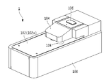
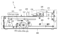
- FIG. 1A is a front perspective view of the staple removing device 1
- FIG. 1B is a rear perspective view of the staple removing device 1.
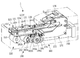
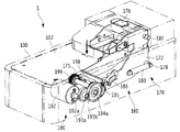
- 2A is a right front left rear perspective view of the inside of the staple removing device 1
- FIG. 2B is a left front right rear perspective view of the inside of the staple removing device 1.
- the staple removing device 1 is a device for automatically removing (removing) staples from a bundle of paper bound by staples, and includes a housing 100 having a substantially rectangular parallelepiped shape and a mounting table 102 on which the bundle of paper is placed. , Located below the mounting table 102 (inside the housing 100 with respect to the mounting table 102), it drives the removing unit 120 and the removing unit 120 for removing staples from the paper bundle mounted on the mounting table 102.
- the first motor 152 and the accommodating portion 200 accommodating the staples removed by the removing unit 120 are provided.
- a cover portion 104 that covers a part of the mounting table 102 is provided above the mounting table 102 (the side on which the paper bundle is placed with respect to the mounting table 102).
- a predetermined gap is formed between the cover portion 104 and the mounting table 102, and a bundle of paper is inserted into this gap.
- An activation switch 106 for operating the staple removing device 1 is provided on the upper surface of the cover portion 104.
- the side where the accommodating portion 200 is provided is the rear side of the staple removal device 1, and the opposite side is the front side of the staple removal device 1.
- the housing 100 is a substantially rectangular parallelepiped box with an opening at the top, and a removing portion 120, a first motor 152, an accommodating portion 200, and the like are provided inside.
- the mounting table 102 is provided so as to cover the opening above the housing 100, and has a mounting surface 102a for mounting a bundle of paper.
- An opening 102b is formed on the mounting surface 102a so that a part of the removing portion 120 can be projected.
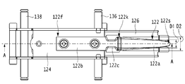
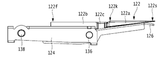
- the removing portion 120 has a predetermined length from the tip portion 122s to the base end portion 122k.
- the removing portion 120 includes a tip portion 122s that can be inserted between the paper bundle and the staple (crown portion Sa), and the wedge plate main body 122a, which is the first portion for removing the staple from the paper bundle, and racks 130 and 131. It has a wedge plate base portion 122f which is a second part driven by the driving force of the first motor 152 received in the above, and a constricted part 122c which is a third part located between the first part and the second part.
- the wedge plate body 122a is composed of an elongated plate-shaped member, and at least the tip portion 122s thereof is formed in a wedge shape so as to be easily inserted between the paper bundle and the staples and to easily pull out the staples from the paper bundle.
- the wedge plate main body 122a has a tapered shape from the base end portion 122k toward the tip end portion 122s. Specifically, in the side view, the plate thickness is gradually reduced from the base end portion 122k toward the tip end portion 122s, and in the top view, the plate width is gradually narrowed toward the tip end portion 122s. It is configured in.
- the wedge plate base 122f supports the wedge plate main body 122a via the constricted portion 122c, and also has a role of receiving the power from the first motor 152 by the racks 130 and 131 and transmitting it to the wedge plate main body 122a.
- the wedge plate base portion 122f includes a plate holder 124 formed of a flat plate having a substantially U-shaped cross section, and a pair of racks 130 and 131 attached to the side surfaces of the plate holder 124.
- a wedge plate main body 122a and an attachment portion 122b extending from the wedge plate base portion 122f are attached to the upper surface of the plate holder 124.
- the racks 130 and 131 are plate-shaped members having substantially the same length as the longitudinal direction of the plate holder 124, and a plurality of teeth (rack) that mesh with the pinion 158 described later are formed on the lower surface thereof, and the first motor 152. Receives the driving force of.
- a paper bundle insertion port 108 for setting a paper bundle in the cover portion 104 is provided between the mounting table 102 and the cover portion 104.
- the start switch 106 is provided on the upper surface of the cover portion 104 so as to be easily operated by the user, and is composed of a button for operating the staple removing device 1.
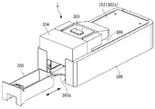
- the accommodating portion 200 is a box body having an opening at the upper side, and is configured to be removable with respect to the opening 100a formed on the rear end surface of the housing 100.
- the accommodating portion 200 is arranged in a space portion in the lower rear part of the housing 100 than the central portion.
- the staple S in a state in which the paper bundle P is bound will be described with reference to FIG. 17A described later.
- the staple S has a crown portion Sa and a pair of leg portions Sb, Sb formed by bending both ends of the crown portion Sa in the longitudinal direction.
- the paper bundle P penetrates a pair of staples Sb, Sb from the bottom layer of a plurality of stacked sheets toward the top layer, and bends the penetrated legs Sb, Sb inward. It is bound by that.
- the binding position of the staple S is, for example, a corner or an edge of the paper. In the present embodiment, the staple S is removed from such a bundle of paper P.
- FIG. 2A is a right front perspective view of the inside of the staple removing device 1 when the removing unit 120 is in the standby position
- FIG. 2B is a left front perspective view of the inside of the staple removing device 1 when the removing unit 120 is in the standby position
- FIG. 2C is a plan view of the inside of the staple removing device 1 when the removing unit 120 is in the standby position
- FIG. 2D is a plan view of the first driving unit 150 and the like inside the staple removing device 1
- FIG. 2E is a plan view of the removing unit 120.
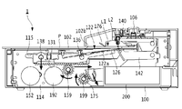
- FIG. 3 is a side sectional view of the inside of the staple removing device 1 when the removing portion 120 is in the standby position.
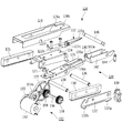
- FIG. 4 is an exploded perspective view of the staple removing mechanism 110.
- 5A is a plan view of the removal unit 120
- FIG. 5B is a side view of the removal unit 120
- FIG. 5C is a cross-sectional view of the removal unit 120 along the line AA.
- FIG. 6 is an exploded perspective view of the paper holding mechanism 160.
- the staple removing device 1 includes a staple removing mechanism 110 that removes the staples S from the paper bundle P, a paper holding mechanism 160 that presses the paper bundle P placed on the mounting table 102, and the above-mentioned accommodating portion 200. ing.
- the staple removing mechanism 110 is arranged inside the housing 100 below the mounting surface 102a of the mounting table 102, and is inserted between the paper bundle P and the staples to form a paper bundle. It has a removing unit 120 that removes the staple S from P, a pressing unit 140, and a first driving unit 150 that drives the removing unit 120.
- the removing portion 120 has a wedge plate 122 inserted between the crown portion Sa of the staple S and the paper bundle P, and the wedge plate 122 of the crown portion Sa and the paper bundle P.
- the racks 130 and 131 to be moved between them are provided.
- a plate holder 124 to which the wedge plate 122 is attached a crown holder 126 that supports the crown portion Sa of the staple S, and a holder 128 that regulates the position of the wedge plate 122.
- a plate holder 124 to which the wedge plate 122 is attached a crown holder 126 that supports the crown portion Sa of the staple S, and a holder 128 that regulates the position of the wedge plate 122.
- the wedge plate 122 is composed of an elongated plate-shaped member, and includes a wedge plate main body 122a, a mounting portion 122b, and a constricted portion 122c.
- the tip 122s is configured to be movable along the plane of the mounting table 102 between the standby position L1 and the removal position L2, and when the tip 122s moves to the removal position L2, the tip 122s is the paper bundle P and the staple. It is inserted between and.
- the standby position L1 of the removing unit 120 means a position where the removing unit 120 is stopped before starting the removing operation.
- the removal position L2 of the removal unit 120 means that the removal unit 120 starts the removal operation, the removal unit 120 is inserted between the crown portion Sa of the staple S and the paper bundle P, and the staple S is removed from the paper bundle P. Means the position.
- the mounting portion 122b is integrally formed on the side of the base end portion 122k of the wedge plate main body 122a, and is mounted on the upper surface of the plate holder 124.
- the constricted portion 122c is a substantially central portion in the longitudinal direction of the wedge plate 122, and is formed between the wedge plate main body 122a and the mounting portion 122b. As shown in FIG. 5A, at least a part of the width direction dimension D1 of the constricted portion 122c is narrower than the width direction dimension D2 of the base end portion 122k of the wedge plate main body 122a, and the staple S is from the wedge plate 122. It becomes narrower than the widthwise dimension D3 (see FIG.
- the "width direction” is the left-right direction in this embodiment, even if it is a direction perpendicular to the thickness direction (height direction) of the wedge plate 122 and the longitudinal direction (movement direction of the removing portion 120). Good.
- the plate holder 124 is composed of a flat plate having a substantially U-shaped cross section, a mounting portion 122b is mounted on the upper surface, and the plate holder 124 is arranged so as to be overlapped above the crown holder 126.
- the crown holder 126 is arranged below the wedge plate 122 with the plate holder 124 in between, and supports the crown portion Sa of the staple S removed from the paper bundle P.
- the crown holder 126 has a groove portion 126a for preventing contact with the pressing portion 140 when the wedge plate 122 moves from the front to the rear, and a staple S removed from the paper bundle P for dropping the staple S into the accommodating portion 200.
- the opening 126b of the crown holder 126 and the constricted portion 122c of the wedge plate 122 attached to the plate holder 124 are arranged so as to be in the same position in a plan view.
- the groove portion 126a is cut out from the tip end portion of the crown holder 126 to substantially the center portion, and has a width slightly wider than the width of the pressing portion 140.
- the opening 126b is formed at a substantially central portion in the longitudinal direction of the crown holder 126 and continuously on the proximal end side of the groove portion 126a, and has a width at least wider than the length of the crown portion Sa of the staple S.
- a spring 125 is arranged between the lower surface on the other end side of the plate holder 124 and the upper surface on the other end side of the crown holder 126, and the elastic force of the spring 125 causes one end side of the wedge plate 122 and one end side of the crown holder 126. Is urged in the direction of approaching.
- one end side indicates the rear side of the staple removal device 1
- the other end side indicates the front side of the staple removal device 1.
- the holder 128 is composed of a flat plate having a substantially U-shaped cross section, and is arranged so as to be overlapped on the upper surface of the plate holder 124.
- the holder 128 has an opening 128a that exposes the wedge plate 122, and a support 128b that regulates the holding portion 140 to be located below the mounting table 102 when at least the removing portion 120 is stopped at the standby position L1. And include.
- a plate-shaped rack 130 having substantially the same length as the longitudinal direction of the plate holder 124 is arranged on the left side of the plate holder 124.
- the rack 130 receives the driving force of the first motor 152.
- a plurality of teeth that mesh with the pinion 158, which will be described later, are formed on the lower surface of the rack 130.
- a plate-shaped rack 131 having substantially the same length as the longitudinal direction of the plate holder 124 is arranged on the right side of the plate holder 124.
- the rack 131 receives the driving force of the first motor 152.
- a plurality of teeth that mesh with the pinion 159, which will be described later, are formed on the lower surface of the rack 131.
- a sensor 134 for detecting the position of the removal unit 120 is provided on the left side of the rack 130, and a flag mounting plate 132 for detecting the position of the removal unit 120 in the front-rear direction is provided. ..
- a first flag 132a for detecting the movement of the wedge plate 122 from the standby position L1 to the removal position L2 is provided at the rear end of the flag mounting plate 132.
- a second flag 132b for detecting the arrival of the wedge plate 122 at the removal position L2 is provided at the front end portion of the flag mounting plate 132.
- the sensor 134 is composed of a transmissive sensor and detects the first flag 132a and the second flag 132b of the rack 130 moving in the front-rear direction.
- the detection signal detected by the sensor 134 is supplied to a control unit (not shown), and the control unit controls the operations of the first motor 152 and the second motor 192 based on the detection signal supplied from the sensor 134.
- the first drive shaft 136 is inserted into the openings formed in each of the flag mounting plate 132, the rack 130, the plate holder 124, the crown holder 126, and the rack 131 from the left side to the right left side of the housing 100.
- the second drive shaft 138 is inserted into the openings formed in the flag mounting plate 132, the rack 130, the plate holder 124, and the rack 131 from the left side to the right side of the housing 100.
- the wedge plate 122, the plate holder 124, the crown holder 126, the holder 128, the racks 130, 131, and the flag mounting plate 132 are assembled by the first drive shaft 136 and the second drive shaft 138 to remove the removal unit 120. It is configured so that it can be integrally moved forward and backward as a removing portion 120.
- the holding portion 140 that regulates the movement of the paper bundle P and the staple S in the insertion direction is arranged on the rear side of the crown portion Sa at the removal position L2 and pushed by the wedge plate 122. It is configured so that it can come into contact with the crown portion Sa.
- the width of the pressing portion 140 is selected, for example, to a length that can support the crown portion Sa that moves from the front to the rear by the pushing force of the wedge plate 122 and that can be inserted into the groove portion 126a of the crown holder 126.
- the presser holder 142 that supports the presser portion 140 is formed of a flat plate processed into a substantially U shape in a top view, and the rear end side of the presser holder 142 is rotatably supported by a shaft 146.
- One end of the tension spring 144 is attached further behind the shaft 146 of the holding holder 142.
- the other end of the tension spring 144 is attached to the left frame 112.
- a convex portion 142a capable of contacting the support portion 128b of the holder 128 is provided at the rear upper end portion of the holding holder 142.
- the first drive unit 150 includes the first motor 152, the gear 153a connected to the output shaft 152a of the first motor 152, and the like in the width direction of the housing 100. It has a pair of pinions 158 and 159 provided at both ends of the shaft 156, which are first pinion portions arranged at predetermined intervals to mesh with the racks 130 and 131.
- the plurality of gears 153a, 153b, 154a, 154b, and 155 form a reduction mechanism.
- the width direction of the housing 100 is the left-right direction in this embodiment, and may be a direction perpendicular to both the moving direction (front-back direction) and the height direction of the removing portion 120.
- the first motor 152 has an output shaft 152a and a motor body 152b, and is composed of, for example, a DC motor, a DC brushless motor, or the like.
- the driving force of the first motor 152 is transmitted to the removal unit 120 via the reduction mechanism, and the removal unit 120 is moved forward or backward.
- the first motor 152 includes a removing portion 120 when the tip portion 122s of the wedge plate main body 122a (first portion) of the removing portion 120 is in the standby position L1. In the embodiment, it is arranged below the second part.
- the lower part of the removal unit 120 means that at least a part of the first motor 152 including the output shaft 152a is located directly below the removal unit 120.
- the first motor 152 is arranged so that the output shaft 152a is parallel to the mounting surface 102a of the mounting table 102, as shown in FIGS. 2D and 3 and the like.
- the wedge plate 122 is arranged so as to be orthogonal to the moving direction from the front to the rear (longitudinal direction of the housing 100).
- the fact that the output shaft 152a is parallel to the mounting surface 102a of the mounting table 102 means that the output shaft 152a is completely parallel and includes a range slightly deviated from the completely parallel. This range may be, for example, within ⁇ 5 °, but may be within ⁇ 10 ° depending on the required accuracy. Similarly, “parallel”, which will be described later, also includes a range that is slightly different from the case where it is completely parallel.
- the gears 153a and 153b are two-stage drive gears, and the diameter of the gear 153a is larger than the diameter of the gear 153b.
- the gear 153a is connected to the output shaft 152a of the first motor 152.
- the gear 153b meshes with the gear 154a.
- the gears 154a and 154b are two-stage drive gears, and the diameter of the gear 154a is larger than the diameter of the gear 154b.
- the gear 154a meshes with the gear 153b, and the gear 154b meshes with the gear 155.
- the right end portion of the shaft 156 extending in the width direction of the housing 100 is attached.
- a pinion 159 that meshes with the rack 131 is attached to the right and left end side of the shaft 156 on the gear 155 side, and a pinion 158 that meshes with the rack 130 is attached to the left end side on the opposite side.
- FIGS. 2A and 6 and the like At least a part of the paper holding mechanism 160 for holding the paper bundle P mounted on the mounting table 102 is located above the mounting table 102 and is configured to be movable. It includes a paper holding portion 170 and a second motor 192 that drives the paper holding portion 170.
- the paper holding portion 170 includes a hold lever 172 to which the parts constituting the paper holding portion are attached, a pair of paper holding racks 174 and 175 extending in the traveling direction at predetermined intervals in the width direction of the housing 100, and a mounting table. It has a paper holding plate 176 that holds the paper bundle P placed on the 102.
- the hold lever 172 has a pair of flat plates 172a and 172b arranged on the rear front side of the housing 100 and arranged at predetermined intervals in the width direction. doing.
- the lower side of the flat plates 172a and 172b is arranged inside the housing 100, and the upper side thereof is arranged so as to be exposed from the mounting table 102 and is covered with the cover portion 104.
- a boss 178 projecting outward is attached to the outer surface of the flat plate 172a.
- One end of the return spring 180 composed of a tension spring is attached to the boss 178, and the other end of the return spring 180 is attached to the left frame 112.
- a boss (not shown) is attached to the outer surface of the flat plate 172b, one end of the return spring 181 is attached to this boss, and the other end of the return spring 181 is attached to the right frame 114.
- the paper holding rack 174 is provided at the lower front and rear ends of the flat plate 172a of the hold lever 172.
- the paper retainer rack 174 is substantially fan-shaped and meshes with the paper retainer pinion 198.
- the paper holding rack 175 is provided at the lower front and rear ends of the flat plate 172b of the hold lever 172.
- the paper retainer rack 175 has a substantially fan shape and meshes with the paper retainer pinion 199 of the second drive unit 190.
- the paper retainer racks 174 and 175 convert the rotational motion of the paper retainer pinions 198 and 199 into a substantially linear motion.
- the paper holding plate 176 moves toward the mounting surface 102a so that the paper bundle P does not deviate from the removal position L2 of the mounting table 102 during the removal operation of the staple S, so that the mounting table 102 It is configured so that the paper bundle P placed on the paper can be pressed.
- the paper holding plate 176 is attached to the flat plates 172a and 172b so as to be parallel to the mounting table 102. Specifically, the left side surface of the paper holding plate 176 is supported by the shaft 186, and the right left side surface of the paper holding plate 176 is supported by the shaft 187.
- the second drive unit 190 includes the second motor 192, the gear 193a connected to the output shaft 192a of the second motor 192, and the housing 100.
- the plurality of gears 193a, 193b, 194a, 194b, 195 constitute a reduction mechanism.
- the second motor 192 is arranged below the removal unit 120 when it is located at the standby position L1.
- the second motor 192 has an output shaft 192a and a motor body 192b, and is composed of, for example, a DC motor, a DC brushless motor, or the like.
- the second motor 192 is driven based on an instruction from a control unit (not shown) to transmit the driving force of the second motor 192 to the paper holding unit 170 via the reduction mechanism to operate the paper holding unit 170.
- the second motor 192 is rearward and forward of the first motor 152, and the tip portion 122s of the wedge plate 122 of the removal portion 120 is in the standby position L1.
- the removal unit 120 in a certain case is arranged below the second unit in the present embodiment.
- the lower part of the removal unit 120 means that at least a part of the second motor 192 including the output shaft 192a is located directly below the removal unit 120.
- the output shaft 192a of the second motor 192 is arranged so as to be parallel to the mounting surface 102a of the mounting table 102, as shown in FIGS. 2D and 3 and the like.
- the wedge plate 122 is arranged so as to be orthogonal to the moving direction from the front to the rear (longitudinal direction of the housing 100).
- the output shaft 192a of the second motor 192 is arranged so as to face the side opposite to the output shaft 152a of the first motor 152, and is preferably oriented in the direction opposite to the output shaft 152a of the first motor 152. It is arranged so that it faces. Specifically, the output shaft 152a of the first motor 152 is arranged so as to face the right direction, and the output shaft 192a of the second motor 192 is arranged so as to face the opposite side to the left.
- the opposite direction means that the output shafts 152a and 192a are oriented 180 degrees opposite to each other and also include a range slightly deviated from the 180 degrees opposite direction. This range may be, for example, within ⁇ 5 °, but may be within ⁇ 10 ° depending on the required accuracy.
- the fact that the output shaft 192a is parallel to the mounting surface 102a of the mounting table 102 means a case where it is completely parallel and a case where it is slightly out of perfect parallelism. This range may be, for example, within ⁇ 5 °, but may be within ⁇ 10 ° depending on the required accuracy.
- the gears 193a and 193b are two-stage drive gears, and the diameter of the gear 193a is larger than the diameter of the gear 193b.
- the gear 193a is connected to the output shaft 192a of the second motor 192.
- the gear 193b meshes with the gear 194a.
- the gears 194a and 194b are two-stage drive gears, and the diameter of the gear 194a is larger than the diameter of the gear 194b.
- the gear 194a meshes with the gear 193b, and the gear 194b meshes with the gear 195.
- the left end portion of the shaft 196 extending in the width direction of the housing 100 is attached.
- a paper holding pinion 198 that meshes with the paper holding rack 174 is attached to the left end side of the shaft 196 on the gear 195 side, and a paper holding pinion 199 that meshes with the paper holding rack 175 is attached to the right end side on the opposite side.
- the accommodating portion 200 is removed by the tip portion 122s of the wedge plate 122 constituting the removing portion 120 in order to be able to accommodate the staple S falling from the paper bundle P. It is located below the removal section 120 when it is at position L2. Further, the accommodating portion 200 is arranged between the flat plates 172a and 172b of the hold lever 172 constituting the paper pressing mechanism 160, and is arranged in an empty space below the pressing holder 142 constituting the staple removing mechanism 110. At least a part of the storage part 200 and a part of the first motor 152 are arranged at the same height.
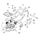
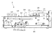
- FIG. 7 is a diagram showing an internal configuration of the staple removing device 1 including the left frame 112, the right frame 114, the front frame 116, and the rear frame 117.
- FIG. 8 is an exploded perspective view of the staple removing device 1 shown in FIG. 7.
- a left frame 112, a right frame 114, a front frame 116, and a rear frame 117 are erected on the outer peripheral portions of the staple pulling mechanism 110 and the paper holding mechanism 160 so as to surround them.
- the left frame 112 is erected on the left side of the staple removal mechanism 110.
- a guide groove 113 extending in the moving direction (longitudinal direction of the housing 100) is formed in the upper portion of the left frame 112 in front of or behind the removing portion 120.
- the guide groove 113 is a first groove 113a for locating the tip portion 122s of the wedge plate 122 of the removing portion 120 waiting at the standby position L1 below the mounting table 102, and the wedge plate 122 of the removing portion 120. It includes a second groove 113b for moving the tip portion 122s from the front side of the removal position L2 in a state of protruding from the mounting table 102 until it passes through the removal position L2.
- the second groove 113b is formed at a position slightly lower than the first groove 113a via the stepped portion 113c.
- the left end portions of the first drive shaft 136 and the second drive shaft 138 of the removal portion 120 are inserted into the guide groove 113.
- the removing portion 120 can be moved along the guide groove 113, and can be moved from the front and the rear along the mounting table 102.
- the right frame 114 is erected on the right side of the staple removal mechanism 110.
- a guide groove 115 extending in the moving direction (longitudinal direction of the housing 100) is formed in the upper part of the right frame 114 in front of or behind the removing portion 120.
- the guide groove 115 is a first groove 115a for locating the tip portion 122s of the wedge plate 122 of the removing portion 120 waiting at the standby position L1 below the mounting table 102, and the wedge plate 122 of the removing portion 120. It includes a second groove 115b for moving the tip portion 122s from the front side of the removal position L2 in a state of protruding from the mounting table 102 until it passes through the removal position L2.
- the second groove 115b is formed at a position slightly lower than the first groove 115a via the stepped portion 115c.
- the right end portions of the first drive shaft 136 and the second drive shaft 138 of the removal portion 120 are inserted into the guide groove 115.
- the removing portion 120 can move along the guide groove 115, and can move forward and backward along the mounting table 102.
- the front frame 116 is erected on the front side of the staple removal mechanism 110, and the rear frame 117 is erected on the rear side of the paper holding mechanism 160.
- FIG. 9A is a perspective view showing the operation of the staple removing mechanism 110 at the standby position L1
- FIG. 9B is a perspective view showing the operation of the staple removing mechanism 110 moving to the removal position L2.
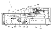
- FIG. 10A is a side view of the main part showing the operation of the staple removing mechanism 110 at the standby position L1
- FIG. 10B is a side view of the main part showing the operation of the staple removing mechanism 110 moving to the removal position L2.
- FIG. 11A is a side view showing the operation of the staple removing mechanism 110 at the standby position L1
- FIG. 11B is a side view of a main part showing the operation of the staple removing mechanism 110 of FIG. 11A.
- FIG. 12A is a side view showing the operation of the staple removing mechanism 110 moving to the removal position L2
- FIG. 12B is a side view of a main part showing the operation of the staple removing mechanism 110 of FIG. 12A.
- FIGS. 11 and 12 for convenience, only the left frame 112 side will be described, but the same operation as the left frame 112 side can be adopted for the right frame 114 side on the opposite side.
- the wedge plate 122 When the staple removing device 1 is in the standby state, the wedge plate 122 is stopped at the standby position L1 of the housing 100, as shown in FIGS. 9A, 10A and 11A. At this time, the second drive shaft 138 is located in the first groove 113a of the guide groove 113 of the left frame 112, and the first drive shaft 136 is located in the second groove 113b of the guide groove 113 of the left frame 112. Therefore, the mounting portion 122b side of the wedge plate 122 is in a raised state, and the wedge plate main body 122a side including the tip portion 122s of the wedge plate 122 is at a lower position than the mounting portion 122b side. As a result, as shown in FIG.
- the wedge plate main body 122a including the tip portion 122s of the wedge plate 122 is lower than the mounting surface 102a of the mounting base 102. Located in. As a result, when the paper bundle P is placed on the mounting table 102, it is possible to prevent the wedge plate 122 from hitting the paper bundle P and being separated from the mounting table.
- the first motor 152 When the start switch 106 of the staple removing device 1 is operated, the first motor 152 is driven as shown in FIGS. 9B and 10B, and the driving force of the first motor 152 is the plurality of gears 153a, 153b, 154a, It is transmitted to the pinions 158 and 159 via 154b and 155.
- the pinions 158 and 159 rotate clockwise in FIG. 10B, and the racks 130 and 131 meshing with the pinions 158 and 159 move from the front to the rear along the mounting table 102 so that the wedge plate 122 moves forward. Move backwards from.
- the second drive shaft 138 moves from the first groove 113a of the guide groove 113 of the left frame 112 to the second groove 113b. Therefore, as the position of the wedge plate 122 on the mounting portion 122b side is lowered, the wedge plate main body 122a side of the wedge plate 122 is lifted with the first drive shaft 136 as a fulcrum.
- the tip portion 122s of the wedge plate 122 is the mounting surface of the mounting base 102. It is located above 102a.
- the wedge plate 122 protrudes from the mounting surface 102a of the mounting table 102 through the opening 102b of the mounting table 102 from the front side of the removing position L2 until it passes through the removal position L2. Move while maintaining. As a result, the tip portion 122s of the wedge plate main body 122a is surely pushed between the paper bundle P and the crown portion Sa.
- FIG. 13A is a perspective view showing the operation of the paper holding mechanism 160 in the standby position
- FIG. 13B is a perspective view showing the operation of the paper holding mechanism 160 moving to the pressing position
- FIG. 14A is a side view of a main part showing the operation of the paper holding mechanism 160 in the standby position
- FIG. 14B is a side view of the main part showing the operation of the paper holding mechanism 160 moving to the pressing position.
- the paper holding plate 176 is stopped at a position at a certain interval from the mounting surface 102a of the mounting table 102.
- the constant interval is an interval at which the lower surface of the paper holding plate 176 does not come into contact with the uppermost layer of the paper bundle P placed on the mounting table 102.
- the second motor 192 When the start switch of the staple removal device 1 is turned on, the second motor 192 is driven. The driving force of the second motor 192 is transmitted to the paper holding pinions 198 and 199 via the gears 193a, 193b, 194a, 194b and 195. Along with this, as shown in FIGS. 13B and 14B, the paper retainer pinions 198 and 199 rotate clockwise, and the paper retainer racks 174 and 175 meshing with the paper retainer pinions 198 and 199 move substantially downward.
- the hold lever 172 rotates counterclockwise with the hold lever shaft 182 as a fulcrum against the elastic force of the return spring 180, and the paper holding plate 176 is placed on the mounting base 102. Moves (descends) in the direction approaching. As a result, the paper bundle P placed on the mounting table 102 is pressed by the paper holding plate 176 with a constant pressing force.
- the second motor 192 is driven in the reverse rotation.
- the paper holding plate 176 moves (rises) in the direction away from the paper bundle P and returns to the standby position shown in FIG. 14A or the like.
- 15A to 15G are side views showing an example of the operation of the staple removing device 1 when the staple S is pulled out from the paper bundle P.
- 16A to 16E are enlarged views of a main part showing an example of the operation of the wedge plate 122 when the staple S is pulled out from the paper bundle P.
- 17A to 17E are diagrams showing the states of the wedge plate 122 and the staple S when the staple S is pulled out from the paper bundle P. In the description of FIG. 15A and the like, for convenience, only the operation on the right side of the staple removing device 1 will be described, but the same operation as on the right side can be adopted for the opposite left side.
- the paper bundle P bound by the staple S is placed on the mounting table 102.
- the user aligns the paper bundle P with the mark indicating the removal position L2 provided on the mounting table 102, and mounts the staple S with the crown portion Sa side facing the mounting table.
- the paper bundle P is bound by staples S.
- the legs Sb and Sb of the staple S penetrate the paper bundle P in the thickness direction of the paper, are bent inward, and bite into the paper surface.
- the first motor 152 is driven.
- the pinion 159 rotates clockwise, so that the removing portion 120 including the rack 131 and the wedge plate 122 moves from the front to the rear.
- the tip portion 122s of the wedge plate main body 122a is positioned below the mounting surface 102a of the mounting base 102, as in the standby position L1. doing.
- the second drive shaft 138 of the removing portion 120 moves to the second groove 115b of the guide groove 115, so that the wedge is shown in FIG. 16B.
- the tip portion 122s of the plate 122 projects from the mounting surface 102a through the opening 102b of the mounting base 102.
- the upper surface of the wedge plate 122 comes into contact with the back surface of the bottom layer of the paper bundle P, and moves from the front to the rear while pressing the paper bundle P.
- the pressing portion 140 rises due to the urging of the tension spring 144, and comes into contact with the crown portion Sa of the paper bundle P that moves from the front to the rear by the pushing force of the wedge plate 122, so that the staple S moves forward. regulate.
- the thickness of the wedge plate 122 pushed between the paper bundle P and the crown portion Sa at the removal position is increased in the side view. It gets thicker. Due to the extension of the tension spring 144, the pressing portion 140 is lowered in contact with the wedge plate 122 and the crown portion Sa following the thickness direction of the wedge plate 122. As a result, as shown in FIG. 17C, the crown portion Sa is pushed by the wedge plate 122 in the direction away from the paper bundle P, and the legs Sb and Sb of the staple S bent inward with respect to the paper surface of the paper bundle P. It extends so as to be substantially orthogonal to each other. As shown in FIG.
- the constricted portion 122c of the wedge plate 122 is located at the removal position L2.
- the width direction dimension D1 of the constricted portion 122c of the wedge plate 122 is narrower than the width direction dimension D3 between the leg portions Sb and Sb of the staple S that springs back.
- the legs Sb and Sb of the staple S are separated from the side surface of the wedge plate 122, and the staple S falls into the accommodating portion 200.
- the first motor 152 is driven in the reverse rotation.
- the pinion 159 rotates counterclockwise, the removal unit 120 including the rack 131 and the wedge plate 122 moves from the rear to the front along the mounting table 102, and the removal unit 120 moves from the removal position L2 to the standby position. Return to L1.
- the second motor 192 is driven by the reverse rotation.
- the paper holding pinion 199 rotates counterclockwise, and the paper holding rack 175 moves substantially upward, so that the paper holding plate 176 moves away from the mounting table 102 via the hold lever 172. Return to the standby position.
- the first motor 152 and the second motor 192 are arranged directly under the removal unit 120 when the wedge plate 122 of the removal unit 120 is in the standby position L1.
- a space portion created by arranging the accommodating portion 200 directly under the removing portion 120 when the wedge plate 122 of the removing portion 120 is at the removing position L2, specifically, the accommodating portion 200. It is a space part that is vacant behind. Therefore, the space behind the accommodating portion 200 is effectively utilized, and the first drive unit 150 including the first motor 152 and the second drive unit 190 including the second motor 192 are centrally arranged in this space. Therefore, the dimensions of the staple removing device 1 in the height direction and the width direction can be suppressed, and the staple removing device 1 can be miniaturized.
- the removed staple S is directly used in the accommodating portion 200. Can be dropped. Therefore, it is not necessary to provide a mechanism such as a guide portion for guiding the removed staple S to the accommodating portion 200, and the structure of the staple removing device 1 can be simplified.
- the staple of the present embodiment is provided with the first drive unit 150 including the first motor 152 and the accommodating unit 200.
- the layout of the removal device 1 is the most lean and optimized layout, and the configuration is simple and the device can be miniaturized.
- the staple removing device 1 according to the present embodiment can be mounted on an image forming device that forms an image on paper.
- the staple removing device 1 according to the present embodiment may be arranged at a position adjacent to the operation panel of the image forming apparatus, or may be inside the image forming apparatus or the post-processing apparatus connected to the image forming apparatus. It may be placed inside.
- This application is based on Japanese Patent Application No. 2019-142573 filed on August 1, 2019, the contents of which are incorporated herein by reference.
Abstract
A staple removal device (1) includes: a placing table (102) on which a bunch of sheets fastened together with a staple are placed; a tip part (122s) insertable between the bunch of sheets and the staple, the tip part (122s) being configured to be movable between a standby position L1 and a removal position L2 along the placing table (102); a removal part (120) having the tip part (122s) to be inserted between the bunch of sheets and the staple when the tip part (122s) is moved to the removal position L2; a first motor (152) for moving the removal part (120); and a storage part (200) for storing a staple removed by the removal part (120). The first motor (152) is located under the removal part (120) when the tip part (122s) is at the standby position (L1), and the storage part (200) is located under the removal part (120) when the tip part (122s) is at the removal position (L2).
Description
本開示は、ステープル取り外し装置に関する。
This disclosure relates to a staple removal device.
従来より、用紙束からステープルを取り外すステープル取り外し装置に関する技術が開示されている(特許文献1、2)。この種のステープル取り外し装置は、用紙束とステープルのクラウン部との間に楔状の板を挿入することで用紙束からステープルを取り外すものである。
Conventionally, a technique relating to a staple removing device for removing staples from a bundle of paper has been disclosed (Patent Documents 1 and 2). This type of staple removing device removes staples from a bundle of paper by inserting a wedge-shaped plate between the bundle of paper and the crown portion of the staple.
特許文献1には、引き抜きピンをシート束とステープルの間に差し込み、その後引き抜きピンを上昇させることでシート束からステープルを取り外すシート処理装置が開示されている。また、特許文献2には、切断手段を原稿束とステープル針との間に挿入し、ステープル針の両脚部を切断した後、ステープル針を原稿束から取り外す綴じ部材除去装置が開示されている。
Patent Document 1 discloses a sheet processing device in which a pull-out pin is inserted between a sheet bundle and a staple, and then the staple is removed from the sheet bundle by raising the pull-out pin. Further, Patent Document 2 discloses a binding member removing device in which a cutting means is inserted between a document bundle and a staple needle, both legs of the staple needle are cut, and then the staple needle is removed from the document bundle.
ところで、特許文献1に記載のシート処理装置では、引き抜きピンを動作させるための引き抜きモータと引き抜きピンを上昇させるための駆動モータがそれぞれ引き抜きピンの上方に配置されている。このため装置の高さ方向の寸法が大きくなってしまうという問題がある。一方、特許文献2に記載の綴じ部材除去装置では、切断手段を駆動するための電動モータが切断手段の側方に配置されている。このため、装置の幅方向の寸法が大きくなってしまうという問題がある。
By the way, in the sheet processing apparatus described in Patent Document 1, a pull-out motor for operating the pull-out pin and a drive motor for raising the pull-out pin are respectively arranged above the pull-out pin. Therefore, there is a problem that the dimension in the height direction of the device becomes large. On the other hand, in the binding member removing device described in Patent Document 2, an electric motor for driving the cutting means is arranged on the side of the cutting means. Therefore, there is a problem that the dimension in the width direction of the device becomes large.
そこで、本開示に係るステープル取り外し装置では、装置の高さ方向及び幅方向の寸法を抑え、装置全体の小型化を図ることを目的とした。
Therefore, the purpose of the staple removing device according to the present disclosure is to suppress the dimensions in the height direction and the width direction of the device and to reduce the size of the entire device.
本開示に係るステープル取り外し装置は、ステープルにより綴じられた用紙束が載置される載置台と、前記載置台の下方に位置し、前記載置台に載置される前記用紙束から前記ステープルを除去する除去部であって、前記用紙束と前記ステープルとの間に挿入可能な先端部を含み、前記先端部が第1位置と第2位置との間を前記載置台に沿って移動可能に構成され、前記先端部が前記第2位置に移動するとき、前記先端部が前記用紙束と前記ステープルとの間に挿入される除去部と、前記除去部を移動させる第1モータと、前記除去部により除去されたステープルを収容する収容部とを備える。そしてこのステープル取り外し装置では、前記第1モータを、前記先端部が前記第1位置にある場合の前記除去部の下方に、前記収容部を、前記先端部が前記第2位置にある場合の前記除去部の下方に位置させた。
The staple removing device according to the present disclosure is located below a mounting table on which a bundle of paper bound by staples is placed and a stack of papers described above, and removes the staples from the bundle of paper mounted on the table described above. A removing portion that includes a tip portion that can be inserted between the paper bundle and the staple, and the tip portion is configured to be movable between the first position and the second position along the above-mentioned stand. Then, when the tip portion moves to the second position, the removal portion in which the tip portion is inserted between the paper bundle and the staple, the first motor that moves the removal portion, and the removal portion. It is provided with a housing for accommodating staples removed by. Then, in this staple removing device, the first motor is placed below the removing portion when the tip portion is in the first position, and the accommodating portion is placed below the removing portion when the tip portion is in the first position. It was positioned below the removal section.
本開示に係るステープル取り外し装置によれば、収容部を除去部が第2位置にある場合の除去部の下方に配置することで、除去部が第1位置にある場合の除去部の下方には空スペースが生じる。この空スペースを有効活用し、ここに第1モータを配置することで、装置の高さ方向及び幅方向の寸法を抑えることができる。これにより、レイアウトを最適化でき、装置全体の小型化を図ることができる。
According to the staple removing device according to the present disclosure, by arranging the accommodating portion below the removing portion when the removing portion is in the second position, the accommodating portion is placed below the removing portion when the removing portion is in the first position. Empty space is created. By effectively utilizing this empty space and arranging the first motor here, the dimensions in the height direction and the width direction of the device can be suppressed. As a result, the layout can be optimized and the entire device can be miniaturized.
以下に図面を参照しながら、本開示の好適な実施の形態について詳細に説明する。
The preferred embodiments of the present disclosure will be described in detail with reference to the drawings below.
[ステープル取り外し装置1の外観構成例]
図1Aはステープル取り外し装置1の前方斜視図、図1Bはステープル取り外し装置1の後方斜視図である。また、図2Aはステープル取り外し装置1の内部の右前左後方斜視図、図2Bはステープル取り外し装置1の内部の左前右後方斜視図である。 [Example of appearance configuration of staple removal device 1]
FIG. 1A is a front perspective view of thestaple removing device 1, and FIG. 1B is a rear perspective view of the staple removing device 1. 2A is a right front left rear perspective view of the inside of the staple removing device 1, and FIG. 2B is a left front right rear perspective view of the inside of the staple removing device 1.
図1Aはステープル取り外し装置1の前方斜視図、図1Bはステープル取り外し装置1の後方斜視図である。また、図2Aはステープル取り外し装置1の内部の右前左後方斜視図、図2Bはステープル取り外し装置1の内部の左前右後方斜視図である。 [Example of appearance configuration of staple removal device 1]
FIG. 1A is a front perspective view of the
ステープル取り外し装置1は、ステープルにより綴られた用紙束からステープルを自動で除去する(取り外す)ための装置であり、略直方体状をなす筐体100と、用紙束が載置される載置台102と、載置台102の下方(載置台102に対して筐体100の内部側)に位置し、載置台102に載置された用紙束からステープルを除去する除去部120と、除去部120を駆動する第1モータ152と、除去部120により除去されたステープルを収容する収容部200とを備える。
The staple removing device 1 is a device for automatically removing (removing) staples from a bundle of paper bound by staples, and includes a housing 100 having a substantially rectangular parallelepiped shape and a mounting table 102 on which the bundle of paper is placed. , Located below the mounting table 102 (inside the housing 100 with respect to the mounting table 102), it drives the removing unit 120 and the removing unit 120 for removing staples from the paper bundle mounted on the mounting table 102. The first motor 152 and the accommodating portion 200 accommodating the staples removed by the removing unit 120 are provided.
載置台102の上方(載置台102に対して用紙束が載置される側)には、載置台102の一部を覆うカバー部104が設けられている。カバー部104と載置台102との間には所定の隙間が形成されており、この隙間に用紙束が挿入される。カバー部104の上面には、ステープル取り外し装置1を動作させる起動スイッチ106が設けられる。なお、本実施の形態において、収容部200が設けられる側をステープル取り外し装置1の後側とし、その反対側をステープル取り外し装置1の前側とする。
Above the mounting table 102 (the side on which the paper bundle is placed with respect to the mounting table 102), a cover portion 104 that covers a part of the mounting table 102 is provided. A predetermined gap is formed between the cover portion 104 and the mounting table 102, and a bundle of paper is inserted into this gap. An activation switch 106 for operating the staple removing device 1 is provided on the upper surface of the cover portion 104. In the present embodiment, the side where the accommodating portion 200 is provided is the rear side of the staple removal device 1, and the opposite side is the front side of the staple removal device 1.
筐体100は、上方が開口した略直方体状の箱体であり、内部に除去部120、第1モータ152、収容部200などが設けられる。
The housing 100 is a substantially rectangular parallelepiped box with an opening at the top, and a removing portion 120, a first motor 152, an accommodating portion 200, and the like are provided inside.
載置台102は、筐体100上方の開口部を覆うようにして設けられており、用紙束を載置するための載置面102aを有する。載置面102aには、除去部120の一部が突出可能なように開口部102bが形成されている。
The mounting table 102 is provided so as to cover the opening above the housing 100, and has a mounting surface 102a for mounting a bundle of paper. An opening 102b is formed on the mounting surface 102a so that a part of the removing portion 120 can be projected.
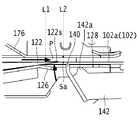
除去部120は、先端部122sから基端部122kにかけて所定の長さを有する。除去部120は、用紙束とステープル(のクラウン部Sa)との間に挿入可能な先端部122sを含み、用紙束からステープルを除去する第1部である楔板本体122aと、ラック130,131で受けた第1モータ152の駆動力で駆動する第2部である楔板基部122fと、第1部と第2部との間に位置する第3部であるくびれ部122cとを有する。
The removing portion 120 has a predetermined length from the tip portion 122s to the base end portion 122k. The removing portion 120 includes a tip portion 122s that can be inserted between the paper bundle and the staple (crown portion Sa), and the wedge plate main body 122a, which is the first portion for removing the staple from the paper bundle, and racks 130 and 131. It has a wedge plate base portion 122f which is a second part driven by the driving force of the first motor 152 received in the above, and a constricted part 122c which is a third part located between the first part and the second part.
楔板本体122aは、細長の板状部材で構成されており、少なくともその先端部122sは、用紙束とステープルとの間に挿入しやすく、かつ用紙束からステープルを引き抜きやすくするために楔状に形成されている。本実施の形態では、楔板本体122aは、基端部122kから先端部122sに向かって先細り形状となっている。具体的には、側面視において、基端部122kから先端部122sに向かって板厚が徐々に薄くなるように構成され、上面視においても先端部122sに向かって板幅が徐々に狭くなるように構成されている。
The wedge plate body 122a is composed of an elongated plate-shaped member, and at least the tip portion 122s thereof is formed in a wedge shape so as to be easily inserted between the paper bundle and the staples and to easily pull out the staples from the paper bundle. Has been done. In the present embodiment, the wedge plate main body 122a has a tapered shape from the base end portion 122k toward the tip end portion 122s. Specifically, in the side view, the plate thickness is gradually reduced from the base end portion 122k toward the tip end portion 122s, and in the top view, the plate width is gradually narrowed toward the tip end portion 122s. It is configured in.
楔板基部122fは、くびれ部122cを介して楔板本体122aを支持するとともに、第1モータ152からの動力を、ラック130,131で受けてそれを楔板本体122aに伝達する役割を有する。楔板基部122fは、図4等に示すように、断面略U字状をなす平板により構成されたプレートホルダ124と、プレートホルダ124の側面に取り付けられた一対のラック130,131とを備える。プレートホルダ124の上面には楔板本体122a、楔板基部122fから延びた取付部122bが取り付けられる。ラック130,131は、プレートホルダ124の長手方向と略同一の長さを有する板状の部材であり、下面には後述するピニオン158に噛み合う複数の歯(ラック)が形成され、第1モータ152の駆動力を受ける。
The wedge plate base 122f supports the wedge plate main body 122a via the constricted portion 122c, and also has a role of receiving the power from the first motor 152 by the racks 130 and 131 and transmitting it to the wedge plate main body 122a. As shown in FIG. 4 and the like, the wedge plate base portion 122f includes a plate holder 124 formed of a flat plate having a substantially U-shaped cross section, and a pair of racks 130 and 131 attached to the side surfaces of the plate holder 124. A wedge plate main body 122a and an attachment portion 122b extending from the wedge plate base portion 122f are attached to the upper surface of the plate holder 124. The racks 130 and 131 are plate-shaped members having substantially the same length as the longitudinal direction of the plate holder 124, and a plurality of teeth (rack) that mesh with the pinion 158 described later are formed on the lower surface thereof, and the first motor 152. Receives the driving force of.
載置台102とカバー部104との間には、用紙束をカバー部104内にセットするための用紙束挿入口108が設けられている。起動スイッチ106は、ユーザーが操作し易いようにカバー部104の上面に設けられ、ステープル取り外し装置1を動作させるボタンで構成される。収容部200は、上方が開口された箱体であって、筐体100の後端面に形成された開口部100aに対して挿抜可能に構成されている。収容部200は、筐体100における中央部よりも後方下部の空間部に配置される。
A paper bundle insertion port 108 for setting a paper bundle in the cover portion 104 is provided between the mounting table 102 and the cover portion 104. The start switch 106 is provided on the upper surface of the cover portion 104 so as to be easily operated by the user, and is composed of a button for operating the staple removing device 1. The accommodating portion 200 is a box body having an opening at the upper side, and is configured to be removable with respect to the opening 100a formed on the rear end surface of the housing 100. The accommodating portion 200 is arranged in a space portion in the lower rear part of the housing 100 than the central portion.
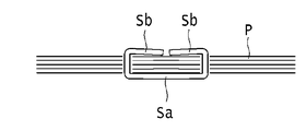
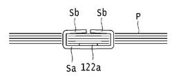
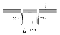
ここで、便宜上、後述する図17Aを参照して用紙束Pを綴じた状態のステープルSについて説明する。ステープルSは、クラウン部Saと、クラウン部Saの長手方向の両端部を折り曲げて形成される一対の脚部Sb,Sbとを有している。用紙束Pは、ステープルSの一対の脚部Sb,Sbを積層された複数枚の用紙の最下層の用紙から最上層の用紙に向けて貫通させ、貫通した脚部Sb,Sbを内側に折り曲げることで綴じ処理される。ステープルSの綴じ位置は、例えば用紙の角部や縁部である。本実施の形態では、このような用紙束PからステープルSを除去する。
Here, for convenience, the staple S in a state in which the paper bundle P is bound will be described with reference to FIG. 17A described later. The staple S has a crown portion Sa and a pair of leg portions Sb, Sb formed by bending both ends of the crown portion Sa in the longitudinal direction. The paper bundle P penetrates a pair of staples Sb, Sb from the bottom layer of a plurality of stacked sheets toward the top layer, and bends the penetrated legs Sb, Sb inward. It is bound by that. The binding position of the staple S is, for example, a corner or an edge of the paper. In the present embodiment, the staple S is removed from such a bundle of paper P.
[ステープル取り外し装置1の内部構成例]
次に、ステープル取り外し装置1の内部構成について説明する。図2Aは除去部120が待機位置にある場合のステープル取り外し装置1の内部の右前方斜視図、図2Bは除去部120が待機位置にある場合のステープル取り外し装置1の内部の左前方斜視図、図2Cは除去部120が待機位置にある場合のステープル取り外し装置1の内部の平面図、図2Dはステープル取り外し装置1の内部の第1駆動部150等の平面図、図2Eは除去部120が待機位置にある場合のステープル取り外し装置1の内部の側面図である。図3は、除去部120が待機位置にある場合のステープル取り外し装置1の内部の側面断面図である。図4は、ステープル抜き機構110の分解斜視図である。図5Aは除去部120の平面図、図5Bは除去部120の側面図、図5Cは除去部120のA-A線に沿った断面図である。図6は、紙押さえ機構160の分解斜視図である。 [Example of internal configuration of staple removal device 1]
Next, the internal configuration of thestaple removing device 1 will be described. FIG. 2A is a right front perspective view of the inside of the staple removing device 1 when the removing unit 120 is in the standby position, and FIG. 2B is a left front perspective view of the inside of the staple removing device 1 when the removing unit 120 is in the standby position. FIG. 2C is a plan view of the inside of the staple removing device 1 when the removing unit 120 is in the standby position, FIG. 2D is a plan view of the first driving unit 150 and the like inside the staple removing device 1, and FIG. 2E is a plan view of the removing unit 120. It is a side view of the inside of the staple removal device 1 when it is in a standby position. FIG. 3 is a side sectional view of the inside of the staple removing device 1 when the removing portion 120 is in the standby position. FIG. 4 is an exploded perspective view of the staple removing mechanism 110. 5A is a plan view of the removal unit 120, FIG. 5B is a side view of the removal unit 120, and FIG. 5C is a cross-sectional view of the removal unit 120 along the line AA. FIG. 6 is an exploded perspective view of the paper holding mechanism 160.
次に、ステープル取り外し装置1の内部構成について説明する。図2Aは除去部120が待機位置にある場合のステープル取り外し装置1の内部の右前方斜視図、図2Bは除去部120が待機位置にある場合のステープル取り外し装置1の内部の左前方斜視図、図2Cは除去部120が待機位置にある場合のステープル取り外し装置1の内部の平面図、図2Dはステープル取り外し装置1の内部の第1駆動部150等の平面図、図2Eは除去部120が待機位置にある場合のステープル取り外し装置1の内部の側面図である。図3は、除去部120が待機位置にある場合のステープル取り外し装置1の内部の側面断面図である。図4は、ステープル抜き機構110の分解斜視図である。図5Aは除去部120の平面図、図5Bは除去部120の側面図、図5Cは除去部120のA-A線に沿った断面図である。図6は、紙押さえ機構160の分解斜視図である。 [Example of internal configuration of staple removal device 1]
Next, the internal configuration of the
ステープル取り外し装置1は、用紙束PからステープルSを除去するステープル抜き機構110と、載置台102上に載置された用紙束Pを押さえ付ける紙押さえ機構160と、上述した収容部200とを備えている。
The staple removing device 1 includes a staple removing mechanism 110 that removes the staples S from the paper bundle P, a paper holding mechanism 160 that presses the paper bundle P placed on the mounting table 102, and the above-mentioned accommodating portion 200. ing.
[ステープル抜き機構110の構成例]
ステープル抜き機構110は、図3等に示すように、載置台102の載置面102aの下方の筐体100の内部に配置され、用紙束Pとステープルとの間に挿入されることで用紙束PからステープルSを除去する除去部120と、押さえ部140と、除去部120を駆動する第1駆動部150とを有している。 [Structure example of staple removal mechanism 110]
As shown in FIG. 3 and the like, thestaple removing mechanism 110 is arranged inside the housing 100 below the mounting surface 102a of the mounting table 102, and is inserted between the paper bundle P and the staples to form a paper bundle. It has a removing unit 120 that removes the staple S from P, a pressing unit 140, and a first driving unit 150 that drives the removing unit 120.
ステープル抜き機構110は、図3等に示すように、載置台102の載置面102aの下方の筐体100の内部に配置され、用紙束Pとステープルとの間に挿入されることで用紙束PからステープルSを除去する除去部120と、押さえ部140と、除去部120を駆動する第1駆動部150とを有している。 [Structure example of staple removal mechanism 110]
As shown in FIG. 3 and the like, the
除去部120は、図5、図9等に示すように、ステープルSのクラウン部Saと用紙束Pとの間に挿入される楔板122と、楔板122をクラウン部Saと用紙束Pの間に移動させるラック130,131を備える。
As shown in FIGS. 5 and 9, the removing portion 120 has a wedge plate 122 inserted between the crown portion Sa of the staple S and the paper bundle P, and the wedge plate 122 of the crown portion Sa and the paper bundle P. The racks 130 and 131 to be moved between them are provided.
本実施例では、除去部120の構成の一例として、楔板122が取り付けられるプレートホルダ124と、ステープルSのクラウン部Saを支持するクラウンホルダ126と、楔板122の位置を規制するホルダ128とを備える。
In this embodiment, as an example of the configuration of the removing portion 120, a plate holder 124 to which the wedge plate 122 is attached, a crown holder 126 that supports the crown portion Sa of the staple S, and a holder 128 that regulates the position of the wedge plate 122. To be equipped.
楔板122は、図4及び図5A~図5C等に示すように、細長の板状部材で構成され、楔板本体122aと取付部122bとくびれ部122cとを含む。先端部122sが待機位置L1と除去位置L2との間を載置台102の平面に沿って移動可能に構成され、先端部122sが除去位置L2に移動するとき、先端部122sが用紙束Pとステープルとの間に挿入される。
As shown in FIGS. 4 and 5A to 5C, the wedge plate 122 is composed of an elongated plate-shaped member, and includes a wedge plate main body 122a, a mounting portion 122b, and a constricted portion 122c. The tip 122s is configured to be movable along the plane of the mounting table 102 between the standby position L1 and the removal position L2, and when the tip 122s moves to the removal position L2, the tip 122s is the paper bundle P and the staple. It is inserted between and.
本実施の形態において、除去部120の待機位置L1とは、除去部120が除去動作を開始する前に停止している位置を意味する。除去部120の除去位置L2とは、除去部120が除去動作を開始し、除去部120がステープルSのクラウン部Saと用紙束Pとの間に挿入され、ステープルSが用紙束Pから除去される位置を意味している。
In the present embodiment, the standby position L1 of the removing unit 120 means a position where the removing unit 120 is stopped before starting the removing operation. The removal position L2 of the removal unit 120 means that the removal unit 120 starts the removal operation, the removal unit 120 is inserted between the crown portion Sa of the staple S and the paper bundle P, and the staple S is removed from the paper bundle P. Means the position.
取付部122bは、楔板本体122aの基端部122kの側に一体形成され、プレートホルダ124の上面に取り付けられている。くびれ部122cは、楔板122の長手方向の略中央部であって、楔板本体122aと取付部122bとの間に形成されている。図5Aに示すように、くびれ部122cの少なくとも一部の幅方向の寸法D1は、楔板本体122aの基端部122kの幅方向の寸法D2よりも狭く、かつ、ステープルSが楔板122から離れる際に、ステープルSの脚部Sb,Sbが内側に折れ曲がっていた状態に戻ろうとするスプリングバックによるステープルSの脚部Sb,Sb間の幅方向の寸法D3(図17E参照)よりも狭くなるように構成される。ここで、「幅方向」は、本実施例では左右方向であり、楔板122の厚さ方向(高さ方向)と、長手方向(除去部120の移動方向)に垂直な方向であってもよい。
The mounting portion 122b is integrally formed on the side of the base end portion 122k of the wedge plate main body 122a, and is mounted on the upper surface of the plate holder 124. The constricted portion 122c is a substantially central portion in the longitudinal direction of the wedge plate 122, and is formed between the wedge plate main body 122a and the mounting portion 122b. As shown in FIG. 5A, at least a part of the width direction dimension D1 of the constricted portion 122c is narrower than the width direction dimension D2 of the base end portion 122k of the wedge plate main body 122a, and the staple S is from the wedge plate 122. It becomes narrower than the widthwise dimension D3 (see FIG. 17E) between the legs Sb and Sb of the staple S due to the springback that tries to return the staple S legs Sb and Sb to the inwardly bent state when they are separated. It is configured as follows. Here, the "width direction" is the left-right direction in this embodiment, even if it is a direction perpendicular to the thickness direction (height direction) of the wedge plate 122 and the longitudinal direction (movement direction of the removing portion 120). Good.
プレートホルダ124は、図4等に示すように、断面略U字状をなす平板により構成され、上面に取付部122bが取り付けられ、クラウンホルダ126の上方に重ねて配置される。
As shown in FIG. 4 and the like, the plate holder 124 is composed of a flat plate having a substantially U-shaped cross section, a mounting portion 122b is mounted on the upper surface, and the plate holder 124 is arranged so as to be overlapped above the crown holder 126.
クラウンホルダ126は、図4等に示すように、プレートホルダ124を挟んで楔板122の下方に配置され、用紙束Pから除去されるステープルSのクラウン部Saを支持する。クラウンホルダ126は、楔板122が前方から後方に移動する際に押さえ部140との接触を防止するための溝部126aと、用紙束Pから除去されたステープルSを収容部200に落下させるための開口部126bとを含む。クラウンホルダ126の開口部126bとプレートホルダ124に取り付けられる楔板122のくびれ部122cとが平面視で同一位置となるように、配置される。溝部126aは、クラウンホルダ126の先端部から略中央部に亘って切り欠かれ、押さえ部140の幅よりも若干広い幅を有する。開口部126bは、クラウンホルダ126の長手方向の略中央部であってかつ溝部126aの基端側に連続して形成され、少なくともステープルSのクラウン部Saの長さよりも広い幅を有する。
As shown in FIG. 4 and the like, the crown holder 126 is arranged below the wedge plate 122 with the plate holder 124 in between, and supports the crown portion Sa of the staple S removed from the paper bundle P. The crown holder 126 has a groove portion 126a for preventing contact with the pressing portion 140 when the wedge plate 122 moves from the front to the rear, and a staple S removed from the paper bundle P for dropping the staple S into the accommodating portion 200. Includes an opening 126b. The opening 126b of the crown holder 126 and the constricted portion 122c of the wedge plate 122 attached to the plate holder 124 are arranged so as to be in the same position in a plan view. The groove portion 126a is cut out from the tip end portion of the crown holder 126 to substantially the center portion, and has a width slightly wider than the width of the pressing portion 140. The opening 126b is formed at a substantially central portion in the longitudinal direction of the crown holder 126 and continuously on the proximal end side of the groove portion 126a, and has a width at least wider than the length of the crown portion Sa of the staple S.
プレートホルダ124の他端側の下面とクラウンホルダ126の他端側の上面との間には、バネ125が配置され、バネ125の弾性力により楔板122の一端側とクラウンホルダ126の一端側とが近づく方向に付勢される。本実施例では、一端側はステープル取り外し装置1の後方を示し、他端側はステープル取り外し装置1の前方を示すものである。
A spring 125 is arranged between the lower surface on the other end side of the plate holder 124 and the upper surface on the other end side of the crown holder 126, and the elastic force of the spring 125 causes one end side of the wedge plate 122 and one end side of the crown holder 126. Is urged in the direction of approaching. In this embodiment, one end side indicates the rear side of the staple removal device 1, and the other end side indicates the front side of the staple removal device 1.
ホルダ128は、断面略U字状をなす平板により構成され、プレートホルダ124の上面に重ねて配置される。ホルダ128は、楔板122を露出させる開口部128aと、少なくとも除去部120が待機位置L1で停止しているときに押さえ部140が載置台102よりも下方に位置するように規制する支持部128bとを含む。
The holder 128 is composed of a flat plate having a substantially U-shaped cross section, and is arranged so as to be overlapped on the upper surface of the plate holder 124. The holder 128 has an opening 128a that exposes the wedge plate 122, and a support 128b that regulates the holding portion 140 to be located below the mounting table 102 when at least the removing portion 120 is stopped at the standby position L1. And include.
プレートホルダ124の左側には、図2B及び図4に示すように、プレートホルダ124の長手方向と略同一の長さを有する板状のラック130が配置されている。ラック130は、第1モータ152の駆動力を受ける。ラック130の下面には、後述するピニオン158に噛み合う複数の歯が形成されている。
As shown in FIGS. 2B and 4, a plate-shaped rack 130 having substantially the same length as the longitudinal direction of the plate holder 124 is arranged on the left side of the plate holder 124. The rack 130 receives the driving force of the first motor 152. A plurality of teeth that mesh with the pinion 158, which will be described later, are formed on the lower surface of the rack 130.
プレートホルダ124の右側には、図2A及び図4に示すように、プレートホルダ124の長手方向と略同一の長さを有する板状のラック131が配置されている。ラック131は、第1モータ152の駆動力を受ける。ラック131の下面には、後述するピニオン159に噛み合う複数の歯が形成されている。
As shown in FIGS. 2A and 4, a plate-shaped rack 131 having substantially the same length as the longitudinal direction of the plate holder 124 is arranged on the right side of the plate holder 124. The rack 131 receives the driving force of the first motor 152. A plurality of teeth that mesh with the pinion 159, which will be described later, are formed on the lower surface of the rack 131.
ラック130の左側には、図4に示すように、除去部120の位置を検出するセンサ134が設けられ、除去部120の前後方向の位置を検出するためのフラグ取付板132が設けられている。フラグ取付板132の後端部には、楔板122の待機位置L1から除去位置L2への移動を検知するための第1フラグ132aが設けられている。フラグ取付板132の前端部には、楔板122の除去位置L2への到達を検知するための第2フラグ132bが設けられている。センサ134は、透過型センサで構成され、前後方向に移動するラック130の第1フラグ132a及び第2フラグ132bを検知する。センサ134により検知された検知信号は、図示しない制御部に供給され、制御部は、センサ134から供給された検知信号に基づいて第1モータ152及び第2モータ192の動作を制御する。
As shown in FIG. 4, a sensor 134 for detecting the position of the removal unit 120 is provided on the left side of the rack 130, and a flag mounting plate 132 for detecting the position of the removal unit 120 in the front-rear direction is provided. .. A first flag 132a for detecting the movement of the wedge plate 122 from the standby position L1 to the removal position L2 is provided at the rear end of the flag mounting plate 132. A second flag 132b for detecting the arrival of the wedge plate 122 at the removal position L2 is provided at the front end portion of the flag mounting plate 132. The sensor 134 is composed of a transmissive sensor and detects the first flag 132a and the second flag 132b of the rack 130 moving in the front-rear direction. The detection signal detected by the sensor 134 is supplied to a control unit (not shown), and the control unit controls the operations of the first motor 152 and the second motor 192 based on the detection signal supplied from the sensor 134.
第1駆動軸136は、筐体100の左側から右左側に向かって、フラグ取付板132、ラック130、プレートホルダ124、クラウンホルダ126、ラック131のそれぞれに形成された開口部に挿入される。
The first drive shaft 136 is inserted into the openings formed in each of the flag mounting plate 132, the rack 130, the plate holder 124, the crown holder 126, and the rack 131 from the left side to the right left side of the housing 100.
第2駆動軸138は、筐体100の左側から右側に向かって、フラグ取付板132、ラック130、プレートホルダ124、ラック131のそれぞれに形成された開口部に挿入される。
The second drive shaft 138 is inserted into the openings formed in the flag mounting plate 132, the rack 130, the plate holder 124, and the rack 131 from the left side to the right side of the housing 100.
このように、第1駆動軸136及び第2駆動軸138によって、楔板122、プレートホルダ124、クラウンホルダ126、ホルダ128、ラック130,131及びフラグ取付板132が組み付けられることで除去部120が構成され、除去部120として一体的に前方及び後方に移動できるようになっている。
In this way, the wedge plate 122, the plate holder 124, the crown holder 126, the holder 128, the racks 130, 131, and the flag mounting plate 132 are assembled by the first drive shaft 136 and the second drive shaft 138 to remove the removal unit 120. It is configured so that it can be integrally moved forward and backward as a removing portion 120.
用紙束P及びステープルSの挿入方向への移動を規制する押さえ部140は、図3及び図4に示すように、除去位置L2にあるクラウン部Saの後方側に配置され、楔板122によって押し込まれるクラウン部Saに当接可能に構成される。押さえ部140の幅は、例えば、楔板122の押し込み力で前方から後方に移動するクラウン部Saを支持可能で、かつクラウンホルダ126の溝部126aに挿入可能な長さに選定される。
As shown in FIGS. 3 and 4, the holding portion 140 that regulates the movement of the paper bundle P and the staple S in the insertion direction is arranged on the rear side of the crown portion Sa at the removal position L2 and pushed by the wedge plate 122. It is configured so that it can come into contact with the crown portion Sa. The width of the pressing portion 140 is selected, for example, to a length that can support the crown portion Sa that moves from the front to the rear by the pushing force of the wedge plate 122 and that can be inserted into the groove portion 126a of the crown holder 126.
押さえ部140を支持する押さえホルダ142は、上面視で略U字状に加工された平板で構成され、押さえホルダ142の後端側が軸146によって回動可能に支持されている。押さえホルダ142の軸146よりもさらに後方には、引張りばね144の一端部が取り付けられている。引張りばね144の他端部は、左フレーム112に取り付けられている。押さえホルダ142の後側上端部には、ホルダ128の支持部128bに当接可能な凸部142aが設けられている。
The presser holder 142 that supports the presser portion 140 is formed of a flat plate processed into a substantially U shape in a top view, and the rear end side of the presser holder 142 is rotatably supported by a shaft 146. One end of the tension spring 144 is attached further behind the shaft 146 of the holding holder 142. The other end of the tension spring 144 is attached to the left frame 112. A convex portion 142a capable of contacting the support portion 128b of the holder 128 is provided at the rear upper end portion of the holding holder 142.
第1駆動部150は、図2A、図2D及び図4に示すように、第1モータ152と、第1モータ152の出力軸152aに接続されるギア153a等と、筐体100の幅方向に、ラック130、131と噛み合う所定の間隔を空けて配置される第1ピニオン部である、軸156の両端に夫々設けられた一対のピニオン158,159とを有している。なお、複数のギア153a,153b,154a,154b,155は、減速機構を構成している。筐体100の幅方向は、本実施例では左右方向であり、除去部120の移動方向(前後方向)と高さ方向の両方に垂直な方向であってもよい。
As shown in FIGS. 2A, 2D, and 4, the first drive unit 150 includes the first motor 152, the gear 153a connected to the output shaft 152a of the first motor 152, and the like in the width direction of the housing 100. It has a pair of pinions 158 and 159 provided at both ends of the shaft 156, which are first pinion portions arranged at predetermined intervals to mesh with the racks 130 and 131. The plurality of gears 153a, 153b, 154a, 154b, and 155 form a reduction mechanism. The width direction of the housing 100 is the left-right direction in this embodiment, and may be a direction perpendicular to both the moving direction (front-back direction) and the height direction of the removing portion 120.
第1モータ152は、出力軸152aとモータ本体152bを有し、例えばDCモータやDCブラシレスモータ等から構成される。第1モータ152は、図示しない制御部からの指示に基づいて駆動することで、減速機構を介して第1モータ152の駆動力を除去部120に伝達し、除去部120を前方又は後方に移動させる。第1モータ152は、図2C、図2D及び図3等に示すように、除去部120の楔板本体122a(第1部)の先端部122sが待機位置L1にある場合における除去部120、本実施の形態では第2部の下方に配置されている。なお、除去部120の下方とは、出力軸152aを含めた第1モータ152の少なくとも一部が除去部120の直下に位置していることを意味する。
The first motor 152 has an output shaft 152a and a motor body 152b, and is composed of, for example, a DC motor, a DC brushless motor, or the like. By driving the first motor 152 based on an instruction from a control unit (not shown), the driving force of the first motor 152 is transmitted to the removal unit 120 via the reduction mechanism, and the removal unit 120 is moved forward or backward. Let me. As shown in FIGS. 2C, 2D, 3 and the like, the first motor 152 includes a removing portion 120 when the tip portion 122s of the wedge plate main body 122a (first portion) of the removing portion 120 is in the standby position L1. In the embodiment, it is arranged below the second part. The lower part of the removal unit 120 means that at least a part of the first motor 152 including the output shaft 152a is located directly below the removal unit 120.
第1モータ152は、出力軸152aが、図2D及び図3等に示すように、載置台102の載置面102aと平行となるように配置される。
The first motor 152 is arranged so that the output shaft 152a is parallel to the mounting surface 102a of the mounting table 102, as shown in FIGS. 2D and 3 and the like.
また、楔板122の前方から後方への移動方向(筐体100の長手方向)に直交するように配置されている。
Further, the wedge plate 122 is arranged so as to be orthogonal to the moving direction from the front to the rear (longitudinal direction of the housing 100).
本実施の形態において、出力軸152aが載置台102の載置面102aと平行であるとは、完全に平行である場合および完全な平行から若干外れた範囲も含むことを意味する。この範囲は、例えば、±5°以内の範囲としうるが、要求される精度によっては、±10°以内の範囲としてもよい。後述の「平行」についても、同様に、完全に平行である場合と若干外れた範囲を含むものとする。
In the present embodiment, the fact that the output shaft 152a is parallel to the mounting surface 102a of the mounting table 102 means that the output shaft 152a is completely parallel and includes a range slightly deviated from the completely parallel. This range may be, for example, within ± 5 °, but may be within ± 10 ° depending on the required accuracy. Similarly, “parallel”, which will be described later, also includes a range that is slightly different from the case where it is completely parallel.
図2A、図2C、図2D及び図2Eに示すように、ギア153a,153bは、2段駆動ギアであり、ギア153aの径はギア153bの径よりも大きく構成される。ギア153aは、第1モータ152の出力軸152aに接続されている。ギア153bは、ギア154aに噛み合っている。ギア154a,154bは、2段駆動ギアであり、ギア154aの径はギア154bの径よりも大きく構成される。ギア154aはギア153bに噛み合い、ギア154bはギア155に噛み合っている。ギア155の中心には筐体100の幅方向に延びる軸156の右端部が取り付けられている。軸156のギア155側の右左端側にはラック131に噛み合うピニオン159が取り付けられ、その反対側の左端側にはラック130に噛み合うピニオン158が取り付けられている。
As shown in FIGS. 2A, 2C, 2D and 2E, the gears 153a and 153b are two-stage drive gears, and the diameter of the gear 153a is larger than the diameter of the gear 153b. The gear 153a is connected to the output shaft 152a of the first motor 152. The gear 153b meshes with the gear 154a. The gears 154a and 154b are two-stage drive gears, and the diameter of the gear 154a is larger than the diameter of the gear 154b. The gear 154a meshes with the gear 153b, and the gear 154b meshes with the gear 155. At the center of the gear 155, the right end portion of the shaft 156 extending in the width direction of the housing 100 is attached. A pinion 159 that meshes with the rack 131 is attached to the right and left end side of the shaft 156 on the gear 155 side, and a pinion 158 that meshes with the rack 130 is attached to the left end side on the opposite side.
[紙押さえ機構160の構成例]
載置台102に載置された用紙束Pを押さえる紙押さえ機構160は、図2A及び図6等に示すように、少なくとも一部が、載置台102の上方に位置し、移動可能に構成された紙押さえ部170と、紙押さえ部170を駆動する第2モータ192とを備えている。 [Structure example of paper holding mechanism 160]
As shown in FIGS. 2A and 6 and the like, at least a part of thepaper holding mechanism 160 for holding the paper bundle P mounted on the mounting table 102 is located above the mounting table 102 and is configured to be movable. It includes a paper holding portion 170 and a second motor 192 that drives the paper holding portion 170.
載置台102に載置された用紙束Pを押さえる紙押さえ機構160は、図2A及び図6等に示すように、少なくとも一部が、載置台102の上方に位置し、移動可能に構成された紙押さえ部170と、紙押さえ部170を駆動する第2モータ192とを備えている。 [Structure example of paper holding mechanism 160]
As shown in FIGS. 2A and 6 and the like, at least a part of the
紙押さえ部170は、紙押さえ部を構成する部品が取り付けられるホールドレバー172と、筐体100の幅方向に所定の間隔を空けて進行方向に延びる一対の紙押さえラック174,175と、載置台102に載置された用紙束Pを押さえる紙押さえ板176とを有している。
The paper holding portion 170 includes a hold lever 172 to which the parts constituting the paper holding portion are attached, a pair of paper holding racks 174 and 175 extending in the traveling direction at predetermined intervals in the width direction of the housing 100, and a mounting table. It has a paper holding plate 176 that holds the paper bundle P placed on the 102.
ホールドレバー172は、図2A、図2E及び図6等に示すように、筐体100の後前方側に配置され、幅方向に所定の間隔を空けて配置された一対の平板172a,172bを有している。平板172a,172bの下部側は筐体100の内部に配置され、その上部側は載置台102から露出するように配置され、カバー部104で覆われている。平板172aの外面には、外側に突出するボス178が取り付けられている。ボス178には、引張りばねで構成されるリターンバネ180の一端部が取り付けられ、リターンバネ180の他端部は左フレーム112に取り付けられている。同様に、平板172bの外面には図示しないボスが取り付けられ、このボスにはリターンバネ181の一端部が取り付けられ、リターンバネ181の他端部が右フレーム114に取り付けられている。
As shown in FIGS. 2A, 2E, 6 and the like, the hold lever 172 has a pair of flat plates 172a and 172b arranged on the rear front side of the housing 100 and arranged at predetermined intervals in the width direction. doing. The lower side of the flat plates 172a and 172b is arranged inside the housing 100, and the upper side thereof is arranged so as to be exposed from the mounting table 102 and is covered with the cover portion 104. A boss 178 projecting outward is attached to the outer surface of the flat plate 172a. One end of the return spring 180 composed of a tension spring is attached to the boss 178, and the other end of the return spring 180 is attached to the left frame 112. Similarly, a boss (not shown) is attached to the outer surface of the flat plate 172b, one end of the return spring 181 is attached to this boss, and the other end of the return spring 181 is attached to the right frame 114.
紙押さえラック174は、ホールドレバー172の平板172aの下方前後端部に設けられる。紙押さえラック174は、略扇状からなり、紙押さえピニオン198に噛み合っている。紙押さえラック175は、ホールドレバー172の平板172bの下方前後端部に設けられる。紙押さえラック175は、略扇状からなり、第2駆動部190の紙押さえピニオン199に噛み合っている。紙押さえラック174,175は、紙押さえピニオン198,199の回転動作を略直線状の動作に変換する。
The paper holding rack 174 is provided at the lower front and rear ends of the flat plate 172a of the hold lever 172. The paper retainer rack 174 is substantially fan-shaped and meshes with the paper retainer pinion 198. The paper holding rack 175 is provided at the lower front and rear ends of the flat plate 172b of the hold lever 172. The paper retainer rack 175 has a substantially fan shape and meshes with the paper retainer pinion 199 of the second drive unit 190. The paper retainer racks 174 and 175 convert the rotational motion of the paper retainer pinions 198 and 199 into a substantially linear motion.
紙押さえ板176は、ステープルSの除去動作中に用紙束Pが載置台102の除去位置L2からズレないようにするために、載置面102aの方向に向けて移動することで、載置台102上に載置される用紙束Pを押圧可能に構成されている。紙押さえ板176は、載置台102に対して平行となるように平板172a,172bに取り付けられている。具体的には、紙押さえ板176の左側面が軸186により支持され、紙押さえ板176の右左側面が軸187により支持される。
The paper holding plate 176 moves toward the mounting surface 102a so that the paper bundle P does not deviate from the removal position L2 of the mounting table 102 during the removal operation of the staple S, so that the mounting table 102 It is configured so that the paper bundle P placed on the paper can be pressed. The paper holding plate 176 is attached to the flat plates 172a and 172b so as to be parallel to the mounting table 102. Specifically, the left side surface of the paper holding plate 176 is supported by the shaft 186, and the right left side surface of the paper holding plate 176 is supported by the shaft 187.
第2駆動部190は、図2B、図2C、図2D及び図6に示すように、第2モータ192と、第2モータ192の出力軸192aに接続されるギア193a等と、筐体100の幅方向に、紙押さえラック174,175と噛み合うように所定の間隔を空けて配置される第2ピニオン部である、軸196の両端に夫々設けられた、一対の紙押さえピニオン198,199とを有している。なお、複数のギア193a,193b,194a,194b,195は、減速機構を構成している。第2モータ192は、除去部120が待機位置L1に位置する際の下方に配置される。
As shown in FIGS. 2B, 2C, 2D and 6, the second drive unit 190 includes the second motor 192, the gear 193a connected to the output shaft 192a of the second motor 192, and the housing 100. A pair of paper retainer pinions 198, 199 provided at both ends of the shaft 196, which are second pinion portions arranged at predetermined intervals so as to mesh with the paper retainer racks 174 and 175 in the width direction. Have. The plurality of gears 193a, 193b, 194a, 194b, 195 constitute a reduction mechanism. The second motor 192 is arranged below the removal unit 120 when it is located at the standby position L1.
第2モータ192は、出力軸192aとモータ本体192bを有し、例えばDCモータやDCブラシレスモータ等から構成される。第2モータ192は、図示しない制御部からの指示に基づいて駆動することで、減速機構を介して第2モータ192の駆動力を紙押さえ部170に伝達し、紙押さえ部170を動作させる。第2モータ192は、図2C、図2D及び図3等に示すように、第1モータ152よりも後前方であって、かつ、除去部120の楔板122の先端部122sが待機位置L1にある場合における除去部120、本実施の形態では第2部の下方に配置されている。なお、除去部120の下方とは、出力軸192aを含めた第2モータ192の少なくとも一部が除去部120の直下に位置していることを意味する。
The second motor 192 has an output shaft 192a and a motor body 192b, and is composed of, for example, a DC motor, a DC brushless motor, or the like. The second motor 192 is driven based on an instruction from a control unit (not shown) to transmit the driving force of the second motor 192 to the paper holding unit 170 via the reduction mechanism to operate the paper holding unit 170. As shown in FIGS. 2C, 2D, 3 and the like, the second motor 192 is rearward and forward of the first motor 152, and the tip portion 122s of the wedge plate 122 of the removal portion 120 is in the standby position L1. The removal unit 120 in a certain case is arranged below the second unit in the present embodiment. The lower part of the removal unit 120 means that at least a part of the second motor 192 including the output shaft 192a is located directly below the removal unit 120.
第2モータ192の出力軸192aは、図2D及び図3等に示すように、載置台102の載置面102aと平行となるように配置される。
The output shaft 192a of the second motor 192 is arranged so as to be parallel to the mounting surface 102a of the mounting table 102, as shown in FIGS. 2D and 3 and the like.
また、楔板122の前方から後方への移動方向(筐体100の長手方向)に直交するように配置されている。
Further, the wedge plate 122 is arranged so as to be orthogonal to the moving direction from the front to the rear (longitudinal direction of the housing 100).
また、第2モータ192の出力軸192aは、第1モータ152の出力軸152aとは反対側を向くように配置されており、好適には、第1モータ152の出力軸152aとは反対方向を向くように配置されている。具体的には、第1モータ152の出力軸152aは右方向を向くように配置され、第2モータ192の出力軸192aはその反対側の左方向を向くように配置される。反対方向とは、出力軸152aと192aとが、180度反対方向を向いている場合に加え、180度反対方向から若干外れた範囲を向いている場合を含むことを意味する。この範囲は、例えば、±5°以内の範囲としうるが、要求される精度によっては、±10°以内の範囲としてもよい。
Further, the output shaft 192a of the second motor 192 is arranged so as to face the side opposite to the output shaft 152a of the first motor 152, and is preferably oriented in the direction opposite to the output shaft 152a of the first motor 152. It is arranged so that it faces. Specifically, the output shaft 152a of the first motor 152 is arranged so as to face the right direction, and the output shaft 192a of the second motor 192 is arranged so as to face the opposite side to the left. The opposite direction means that the output shafts 152a and 192a are oriented 180 degrees opposite to each other and also include a range slightly deviated from the 180 degrees opposite direction. This range may be, for example, within ± 5 °, but may be within ± 10 ° depending on the required accuracy.
本実施の形態において、出力軸192aが載置台102の載置面102aと平行であるとは、完全に平行である場合および完全な平行から若干外れた範囲である場合を意味する。この範囲は、例えば、±5°以内の範囲としうるが、要求される精度によっては、±10°以内の範囲としてもよい。
In the present embodiment, the fact that the output shaft 192a is parallel to the mounting surface 102a of the mounting table 102 means a case where it is completely parallel and a case where it is slightly out of perfect parallelism. This range may be, for example, within ± 5 °, but may be within ± 10 ° depending on the required accuracy.
図2B、図2C、図2D、図2E及び図6に示すように、ギア193a,193bは、2段駆動ギアであり、ギア193aの径はギア193bの径よりも大きく構成される。ギア193aは、第2モータ192の出力軸192aに接続されている。ギア193bは、ギア194aに噛み合っている。ギア194a,194bは、2段駆動ギアであり、ギア194aの径はギア194bの径よりも大きく構成される。ギア194aはギア193bに噛み合い、ギア194bはギア195に噛み合っている。ギア195の中心には筐体100の幅方向に延びる軸196の左端部が取り付けられている。軸196のギア195側の左端側には紙押さえラック174に噛み合う紙押さえピニオン198が取り付けられ、その反対側の右端側には紙押さえラック175に噛み合う紙押さえピニオン199が取り付けられている。
As shown in FIGS. 2B, 2C, 2D, 2E and 6, the gears 193a and 193b are two-stage drive gears, and the diameter of the gear 193a is larger than the diameter of the gear 193b. The gear 193a is connected to the output shaft 192a of the second motor 192. The gear 193b meshes with the gear 194a. The gears 194a and 194b are two-stage drive gears, and the diameter of the gear 194a is larger than the diameter of the gear 194b. The gear 194a meshes with the gear 193b, and the gear 194b meshes with the gear 195. At the center of the gear 195, the left end portion of the shaft 196 extending in the width direction of the housing 100 is attached. A paper holding pinion 198 that meshes with the paper holding rack 174 is attached to the left end side of the shaft 196 on the gear 195 side, and a paper holding pinion 199 that meshes with the paper holding rack 175 is attached to the right end side on the opposite side.
[収容部200の構成例]
収容部200は、図2A、図2B及び図3等に示すように、用紙束Pから落下するステープルSを収容可能とするために、除去部120を構成する楔板122の先端部122sが除去位置L2にある場合の除去部120の下方に位置する。また、収容部200は、紙押さえ機構160を構成するホールドレバー172の平板172a,172b間であって、ステープル抜き機構110を構成する押さえホルダ142の下方の空いた空間部に配置される。収納部200の少なくとも一部と、第1モータ152の一部は、同じ高さに配置されている。 [Structure example of accommodating portion 200]
As shown in FIGS. 2A, 2B, 3 and the like, theaccommodating portion 200 is removed by the tip portion 122s of the wedge plate 122 constituting the removing portion 120 in order to be able to accommodate the staple S falling from the paper bundle P. It is located below the removal section 120 when it is at position L2. Further, the accommodating portion 200 is arranged between the flat plates 172a and 172b of the hold lever 172 constituting the paper pressing mechanism 160, and is arranged in an empty space below the pressing holder 142 constituting the staple removing mechanism 110. At least a part of the storage part 200 and a part of the first motor 152 are arranged at the same height.
収容部200は、図2A、図2B及び図3等に示すように、用紙束Pから落下するステープルSを収容可能とするために、除去部120を構成する楔板122の先端部122sが除去位置L2にある場合の除去部120の下方に位置する。また、収容部200は、紙押さえ機構160を構成するホールドレバー172の平板172a,172b間であって、ステープル抜き機構110を構成する押さえホルダ142の下方の空いた空間部に配置される。収納部200の少なくとも一部と、第1モータ152の一部は、同じ高さに配置されている。 [Structure example of accommodating portion 200]
As shown in FIGS. 2A, 2B, 3 and the like, the
[左フレーム112等の構成例]
図7は、左フレーム112、右フレーム114、前フレーム116及び後フレーム117を含むステープル取り外し装置1の内部構成を示す図である。図8は、図7に示すステープル取り外し装置1の分解斜視図である。 [Configuration example ofleft frame 112, etc.]
FIG. 7 is a diagram showing an internal configuration of thestaple removing device 1 including the left frame 112, the right frame 114, the front frame 116, and the rear frame 117. FIG. 8 is an exploded perspective view of the staple removing device 1 shown in FIG. 7.
図7は、左フレーム112、右フレーム114、前フレーム116及び後フレーム117を含むステープル取り外し装置1の内部構成を示す図である。図8は、図7に示すステープル取り外し装置1の分解斜視図である。 [Configuration example of
FIG. 7 is a diagram showing an internal configuration of the
ステープル抜き機構110及び紙押さえ機構160の外周部には、これらを囲むように左フレーム112、右フレーム114、前フレーム116及び後フレーム117が立設されている。
A left frame 112, a right frame 114, a front frame 116, and a rear frame 117 are erected on the outer peripheral portions of the staple pulling mechanism 110 and the paper holding mechanism 160 so as to surround them.
左フレーム112は、ステープル抜き機構110の左側に立設される。左フレーム112の上部には、除去部120の前方又は後方に移動方向(筐体100の長手方向)に沿って延びるガイド溝113が形成されている。ガイド溝113は、待機位置L1で待機している除去部120の楔板122の先端部122sを載置台102よりも下方に位置させるための第1溝113aと、除去部120の楔板122の先端部122sを除去位置L2の手前から除去位置L2を通過するまで載置台102から突出させた状態で移動させるための第2溝113bとを含む。第2溝113bは、段差部113cを介して第1溝113aよりも若干低い位置に形成されている。ガイド溝113には、除去部120の第1駆動軸136及び第2駆動軸138の左端部が挿通される。これにより、除去部120は、ガイド溝113に沿って移動可能となり、載置台102に沿って前方から及び後方に移動できるようになっている。
The left frame 112 is erected on the left side of the staple removal mechanism 110. A guide groove 113 extending in the moving direction (longitudinal direction of the housing 100) is formed in the upper portion of the left frame 112 in front of or behind the removing portion 120. The guide groove 113 is a first groove 113a for locating the tip portion 122s of the wedge plate 122 of the removing portion 120 waiting at the standby position L1 below the mounting table 102, and the wedge plate 122 of the removing portion 120. It includes a second groove 113b for moving the tip portion 122s from the front side of the removal position L2 in a state of protruding from the mounting table 102 until it passes through the removal position L2. The second groove 113b is formed at a position slightly lower than the first groove 113a via the stepped portion 113c. The left end portions of the first drive shaft 136 and the second drive shaft 138 of the removal portion 120 are inserted into the guide groove 113. As a result, the removing portion 120 can be moved along the guide groove 113, and can be moved from the front and the rear along the mounting table 102.
右フレーム114は、ステープル抜き機構110の右側に立設される。右フレーム114の上部には除去部120の前方又は後方に移動方向(筐体100の長手方向)に沿って延びるガイド溝115が形成されている。ガイド溝115は、待機位置L1で待機している除去部120の楔板122の先端部122sを載置台102よりも下方に位置させるための第1溝115aと、除去部120の楔板122の先端部122sを除去位置L2の手前から除去位置L2を通過するまで載置台102から突出させた状態で移動させるための第2溝115bとを含む。第2溝115bは、段差部115cを介して第1溝115aよりも若干低い位置に形成されている。ガイド溝115には、除去部120の第1駆動軸136及び第2駆動軸138の右端部が挿通される。これにより、除去部120は、ガイド溝115に沿って移動可能となり、載置台102に沿って前方及び後方に移動できるようになっている。
The right frame 114 is erected on the right side of the staple removal mechanism 110. A guide groove 115 extending in the moving direction (longitudinal direction of the housing 100) is formed in the upper part of the right frame 114 in front of or behind the removing portion 120. The guide groove 115 is a first groove 115a for locating the tip portion 122s of the wedge plate 122 of the removing portion 120 waiting at the standby position L1 below the mounting table 102, and the wedge plate 122 of the removing portion 120. It includes a second groove 115b for moving the tip portion 122s from the front side of the removal position L2 in a state of protruding from the mounting table 102 until it passes through the removal position L2. The second groove 115b is formed at a position slightly lower than the first groove 115a via the stepped portion 115c. The right end portions of the first drive shaft 136 and the second drive shaft 138 of the removal portion 120 are inserted into the guide groove 115. As a result, the removing portion 120 can move along the guide groove 115, and can move forward and backward along the mounting table 102.
前フレーム116は、ステープル抜き機構110の前方側に立設され、後フレーム117は、紙押さえ機構160の後方側に立設されている。
The front frame 116 is erected on the front side of the staple removal mechanism 110, and the rear frame 117 is erected on the rear side of the paper holding mechanism 160.
[ステープル抜き機構110の動作例]
次に、用紙束PからステープルSを除去する場合における、ステープル抜き機構110の動作の一例について説明する。 [Operation example of staple removal mechanism 110]
Next, an example of the operation of thestaple removing mechanism 110 when the staple S is removed from the paper bundle P will be described.
次に、用紙束PからステープルSを除去する場合における、ステープル抜き機構110の動作の一例について説明する。 [Operation example of staple removal mechanism 110]
Next, an example of the operation of the
図9Aは待機位置L1にいるステープル抜き機構110の動作を示す斜視図、図9Bは除去位置L2に移動するステープル抜き機構110の動作を示す斜視図である。図10Aは待機位置L1にいるステープル抜き機構110の動作を示す要部側面図、図10Bは除去位置L2に移動するステープル抜き機構110の動作を示す要部側面図である。図11Aは待機位置L1にいるステープル抜き機構110の動作を示す側面図、図11Bは図11Aのステープル抜き機構110の動作を示す要部側面図である。図12Aは除去位置L2に移動するステープル抜き機構110の動作を示す側面図、図12Bは図12Aのステープル抜き機構110の動作を示す要部側面図である。なお、図11及び図12では、便宜上、左フレーム112側についてのみ説明するが、その反対側の右フレーム114側も左フレーム112側と同様の動作を採用できるものとする。
FIG. 9A is a perspective view showing the operation of the staple removing mechanism 110 at the standby position L1, and FIG. 9B is a perspective view showing the operation of the staple removing mechanism 110 moving to the removal position L2. FIG. 10A is a side view of the main part showing the operation of the staple removing mechanism 110 at the standby position L1, and FIG. 10B is a side view of the main part showing the operation of the staple removing mechanism 110 moving to the removal position L2. FIG. 11A is a side view showing the operation of the staple removing mechanism 110 at the standby position L1, and FIG. 11B is a side view of a main part showing the operation of the staple removing mechanism 110 of FIG. 11A. 12A is a side view showing the operation of the staple removing mechanism 110 moving to the removal position L2, and FIG. 12B is a side view of a main part showing the operation of the staple removing mechanism 110 of FIG. 12A. In FIGS. 11 and 12, for convenience, only the left frame 112 side will be described, but the same operation as the left frame 112 side can be adopted for the right frame 114 side on the opposite side.
ステープル取り外し装置1が待機状態である場合、図9A、図10A及び図11Aに示すように、楔板122は、筐体100の待機位置L1で停止している。このとき、第2駆動軸138は左フレーム112のガイド溝113の第1溝113aに位置し、第1駆動軸136は左フレーム112のガイド溝113の第2溝113bに位置している。そのため、楔板122の取付部122b側が持ち上がった状態となり、楔板122の先端部122sを含む楔板本体122a側が取付部122b側よりも低い位置となる。これにより、図11Bに示すように、除去部120の先端部122sが待機位置L1にいる場合、楔板122の先端部122sを含む楔板本体122aが載置台102の載置面102aよりも下方に位置する。これにより、用紙束Pを載置台102上に載置する際に、楔板122が用紙束Pに当たって載置台から離れてしまう不具合が生じてしまうことを防止できる。
When the staple removing device 1 is in the standby state, the wedge plate 122 is stopped at the standby position L1 of the housing 100, as shown in FIGS. 9A, 10A and 11A. At this time, the second drive shaft 138 is located in the first groove 113a of the guide groove 113 of the left frame 112, and the first drive shaft 136 is located in the second groove 113b of the guide groove 113 of the left frame 112. Therefore, the mounting portion 122b side of the wedge plate 122 is in a raised state, and the wedge plate main body 122a side including the tip portion 122s of the wedge plate 122 is at a lower position than the mounting portion 122b side. As a result, as shown in FIG. 11B, when the tip portion 122s of the removal portion 120 is in the standby position L1, the wedge plate main body 122a including the tip portion 122s of the wedge plate 122 is lower than the mounting surface 102a of the mounting base 102. Located in. As a result, when the paper bundle P is placed on the mounting table 102, it is possible to prevent the wedge plate 122 from hitting the paper bundle P and being separated from the mounting table.
ステープル取り外し装置1の起動スイッチ106が操作されると、図9B及び図10Bに示すように、第1モータ152が駆動され、第1モータ152の駆動力は、複数のギア153a,153b,154a,154b,155を介してピニオン158,159に伝達される。これに伴い、ピニオン158,159が図10Bにおいて時計回りに回転し、ピニオン158,159に噛み合っているラック130,131が載置台102に沿って前方から後方に移動することで楔板122が前方から後方に移動する。
When the start switch 106 of the staple removing device 1 is operated, the first motor 152 is driven as shown in FIGS. 9B and 10B, and the driving force of the first motor 152 is the plurality of gears 153a, 153b, 154a, It is transmitted to the pinions 158 and 159 via 154b and 155. Along with this, the pinions 158 and 159 rotate clockwise in FIG. 10B, and the racks 130 and 131 meshing with the pinions 158 and 159 move from the front to the rear along the mounting table 102 so that the wedge plate 122 moves forward. Move backwards from.
このとき、第2駆動軸138は、図12Aに示すように、左フレーム112のガイド溝113の第1溝113aから第2溝113bに移動する。そのため、楔板122の取付部122b側の位置が下がることで、楔板122の楔板本体122a側が第1駆動軸136を支点として持ち上がる。ここで、楔板本体122aの上面は、取付部122bの上面よりも若干突出した構造となっているので、図12Bに示すように、楔板122の先端部122sは載置台102の載置面102aよりも上方に位置する。本実施の形態では、楔板122は、除去位置L2の手前から除去位置L2を通過するまでの間、載置台102の開口部102bを介して載置台102の載置面102aから突出した状態を維持しつつ移動する。これにより、楔板本体122aの先端部122sが用紙束Pとクラウン部Saとの間に確実に押し込まれる。
At this time, as shown in FIG. 12A, the second drive shaft 138 moves from the first groove 113a of the guide groove 113 of the left frame 112 to the second groove 113b. Therefore, as the position of the wedge plate 122 on the mounting portion 122b side is lowered, the wedge plate main body 122a side of the wedge plate 122 is lifted with the first drive shaft 136 as a fulcrum. Here, since the upper surface of the wedge plate main body 122a has a structure slightly protruding from the upper surface of the mounting portion 122b, as shown in FIG. 12B, the tip portion 122s of the wedge plate 122 is the mounting surface of the mounting base 102. It is located above 102a. In the present embodiment, the wedge plate 122 protrudes from the mounting surface 102a of the mounting table 102 through the opening 102b of the mounting table 102 from the front side of the removing position L2 until it passes through the removal position L2. Move while maintaining. As a result, the tip portion 122s of the wedge plate main body 122a is surely pushed between the paper bundle P and the crown portion Sa.
[紙押さえ機構160の動作例]
次に、用紙束PからステープルSを除去する場合における、紙押さえ機構160の動作の一例について説明する。 [Operation example of paper holding mechanism 160]
Next, an example of the operation of thepaper holding mechanism 160 when the staple S is removed from the paper bundle P will be described.
次に、用紙束PからステープルSを除去する場合における、紙押さえ機構160の動作の一例について説明する。 [Operation example of paper holding mechanism 160]
Next, an example of the operation of the
図13Aは待機位置にいる紙押さえ機構160の動作を示す斜視図、図13Bは押圧位置に移動する紙押さえ機構160の動作を示す斜視図である。図14Aは待機位置にいる紙押さえ機構160の動作を示す要部側面図、図14Bは押圧位置に移動する紙押さえ機構160の動作を示す要部側面図である。
FIG. 13A is a perspective view showing the operation of the paper holding mechanism 160 in the standby position, and FIG. 13B is a perspective view showing the operation of the paper holding mechanism 160 moving to the pressing position. FIG. 14A is a side view of a main part showing the operation of the paper holding mechanism 160 in the standby position, and FIG. 14B is a side view of the main part showing the operation of the paper holding mechanism 160 moving to the pressing position.
図13A及び図14Aに示すように、ステープル取り外し装置1が待機位置である場合、紙押さえ板176は、載置台102の載置面102aから一定間隔を空けた位置で停止している。一定間隔とは、載置台102上に載置される用紙束Pの最上層の用紙に、紙押さえ板176の下面が接触しない間隔である。
As shown in FIGS. 13A and 14A, when the staple removing device 1 is in the standby position, the paper holding plate 176 is stopped at a position at a certain interval from the mounting surface 102a of the mounting table 102. The constant interval is an interval at which the lower surface of the paper holding plate 176 does not come into contact with the uppermost layer of the paper bundle P placed on the mounting table 102.
ステープル取り外し装置1の起動スイッチがオンされると、第2モータ192が駆動される。第2モータ192の駆動力は、ギア193a,193b,194a,194b,195を介して紙押さえピニオン198,199に伝達される。これに伴い、図13B及び図14Bに示すように、紙押さえピニオン198,199が時計回りに回転し、紙押さえピニオン198,199に噛み合っている紙押さえラック174,175が略下方に移動する。紙押さえラック174,175が略下方に移動すると、ホールドレバー172は、リターンバネ180の弾性力に抗してホールドレバー軸182を支点として反時計回りに回転し、紙押さえ板176が載置台102に近づく方向に移動(下降)する。これにより、載置台102上に載置される用紙束Pが紙押さえ板176により一定の押圧力にて押圧される。
When the start switch of the staple removal device 1 is turned on, the second motor 192 is driven. The driving force of the second motor 192 is transmitted to the paper holding pinions 198 and 199 via the gears 193a, 193b, 194a, 194b and 195. Along with this, as shown in FIGS. 13B and 14B, the paper retainer pinions 198 and 199 rotate clockwise, and the paper retainer racks 174 and 175 meshing with the paper retainer pinions 198 and 199 move substantially downward. When the paper holding racks 174 and 175 move substantially downward, the hold lever 172 rotates counterclockwise with the hold lever shaft 182 as a fulcrum against the elastic force of the return spring 180, and the paper holding plate 176 is placed on the mounting base 102. Moves (descends) in the direction approaching. As a result, the paper bundle P placed on the mounting table 102 is pressed by the paper holding plate 176 with a constant pressing force.
用紙束PからのステープルSの除去動作が終了すると、第2モータ192が逆回転で駆動される。これにより、紙押さえ板176は、用紙束Pから離れる方向に移動(上昇)し、図14A等に示した待機位置に戻る。
When the operation of removing the staple S from the paper bundle P is completed, the second motor 192 is driven in the reverse rotation. As a result, the paper holding plate 176 moves (rises) in the direction away from the paper bundle P and returns to the standby position shown in FIG. 14A or the like.
[ステープル取り外し装置1の動作例]
次に、用紙束PからステープルSを引き抜く場合におけるステープル取り外し装置1の動作等について説明する。なお、ステープル抜き機構110及び紙押さえ機構160の動作については、図9A及び図13A等と同様であるため、詳細な説明は省略する。 [Operation example of staple removal device 1]
Next, the operation of thestaple removing device 1 when the staple S is pulled out from the paper bundle P will be described. Since the operations of the staple removing mechanism 110 and the paper holding mechanism 160 are the same as those in FIGS. 9A and 13A, detailed description thereof will be omitted.
次に、用紙束PからステープルSを引き抜く場合におけるステープル取り外し装置1の動作等について説明する。なお、ステープル抜き機構110及び紙押さえ機構160の動作については、図9A及び図13A等と同様であるため、詳細な説明は省略する。 [Operation example of staple removal device 1]
Next, the operation of the
図15A~図15Gは、用紙束PからステープルSを引き抜く場合におけるステープル取り外し装置1の動作の一例を示す側面図である。図16A~図16Eは、用紙束PからステープルSを引き抜く場合における楔板122の動作の一例を示す要部拡大図である。図17A~図17Eは、用紙束PからステープルSを引き抜く場合における楔板122及びステープルSの状態を示す図である。なお、図15A等の説明では、便宜上ステープル取り外し装置1の右側の動作についてのみ説明するが、その反対の左側についても右側と同様の動作を採用することができるものとする。
15A to 15G are side views showing an example of the operation of the staple removing device 1 when the staple S is pulled out from the paper bundle P. 16A to 16E are enlarged views of a main part showing an example of the operation of the wedge plate 122 when the staple S is pulled out from the paper bundle P. 17A to 17E are diagrams showing the states of the wedge plate 122 and the staple S when the staple S is pulled out from the paper bundle P. In the description of FIG. 15A and the like, for convenience, only the operation on the right side of the staple removing device 1 will be described, but the same operation as on the right side can be adopted for the opposite left side.
図15Aに示すように、用紙束PからステープルSを除去する場合には、まず、ステープルSにより綴じられた用紙束Pが載置台102上に載置される。ユーザーは、載置台102上に設けられた除去位置L2を示す目印に用紙束Pを位置合わせして、ステープルSのクラウン部Sa側を載台に向けて載置する。図17Aに示すように、用紙束PはステープルSにより綴じられている。ステープルSの脚部Sb,Sbは、用紙束Pを用紙の厚み方向に貫通して内側に折り曲げられ、用紙面に食い込んでいる。
As shown in FIG. 15A, when removing the staple S from the paper bundle P, first, the paper bundle P bound by the staple S is placed on the mounting table 102. The user aligns the paper bundle P with the mark indicating the removal position L2 provided on the mounting table 102, and mounts the staple S with the crown portion Sa side facing the mounting table. As shown in FIG. 17A, the paper bundle P is bound by staples S. The legs Sb and Sb of the staple S penetrate the paper bundle P in the thickness direction of the paper, are bent inward, and bite into the paper surface.
次に、ユーザーによりステープル取り外し装置1の起動スイッチ106が押されると、第2モータ192駆動が開始される。これにより、図15Bに示すように、紙押さえ板176が載置台102に近づく方向に移動(下降)し、用紙束Pが紙押さえ板176により一定の押圧力で押圧される。
Next, when the start switch 106 of the staple removal device 1 is pressed by the user, the second motor 192 drive is started. As a result, as shown in FIG. 15B, the paper holding plate 176 moves (descends) in the direction approaching the mounting table 102, and the paper bundle P is pressed by the paper holding plate 176 with a constant pressing force.
続けて、第2モータ192の駆動開始から所定時間経過後、第1モータ152が駆動される。これにより、ピニオン159が時計回りに回転することで、ラック131及び楔板122を含む除去部120が前方から後方に移動する。除去部120の前方から後方に移動開始時においては、待機位置L1と同様に、図16Aに示すように、楔板本体122aの先端部122sが載置台102の載置面102aよりも下方に位置している。
Subsequently, after a predetermined time has elapsed from the start of driving the second motor 192, the first motor 152 is driven. As a result, the pinion 159 rotates clockwise, so that the removing portion 120 including the rack 131 and the wedge plate 122 moves from the front to the rear. At the start of movement from the front to the rear of the removing portion 120, as shown in FIG. 16A, the tip portion 122s of the wedge plate main body 122a is positioned below the mounting surface 102a of the mounting base 102, as in the standby position L1. doing.
除去部120の先端側が除去位置L2の手前に前方から後方に移動すると、除去部120の第2駆動軸138がガイド溝115の第2溝115bに移動するため、図16Bに示すように、楔板122の先端部122sが載置台102の開口部102bを介して載置面102aから突出する。楔板122は、その上面が用紙束Pの最下層の用紙の裏面に接触し、用紙束Pを押圧した状態で前方から後方に移動する。
When the tip side of the removing portion 120 moves from the front to the rear in front of the removing position L2, the second drive shaft 138 of the removing portion 120 moves to the second groove 115b of the guide groove 115, so that the wedge is shown in FIG. 16B. The tip portion 122s of the plate 122 projects from the mounting surface 102a through the opening 102b of the mounting base 102. The upper surface of the wedge plate 122 comes into contact with the back surface of the bottom layer of the paper bundle P, and moves from the front to the rear while pressing the paper bundle P.
楔板122の先端側が除去位置L2まで移動すると、図15C及び図16Cに示すように、クラウン部Saと用紙束Pとの間に押し込まれる。このとき、図17Bに示すように、ステープルSの脚部Sb,Sbが、用紙束Pの用紙面に食い込んだ状態から、用紙束Pの用紙面に略平行な状態となる。この状態で楔板122がさらに前方から後方に移動していくと、図16Dに示すように、押さえホルダ142の凸部142aがホルダ128の支持部128bから外れる。これにより、押さえ部140が引張りばね144の付勢により上昇し、楔板122の押し込み力で前方から後方に移動する用紙束Pのクラウン部Saに当接して、ステープルSの前方への移動を規制する。
When the tip end side of the wedge plate 122 moves to the removal position L2, it is pushed between the crown portion Sa and the paper bundle P as shown in FIGS. 15C and 16C. At this time, as shown in FIG. 17B, the legs Sb and Sb of the staple S go from the state where they bite into the paper surface of the paper bundle P to the state where they are substantially parallel to the paper surface of the paper bundle P. When the wedge plate 122 further moves from the front to the rear in this state, the convex portion 142a of the holding holder 142 comes off from the supporting portion 128b of the holder 128, as shown in FIG. 16D. As a result, the pressing portion 140 rises due to the urging of the tension spring 144, and comes into contact with the crown portion Sa of the paper bundle P that moves from the front to the rear by the pushing force of the wedge plate 122, so that the staple S moves forward. regulate.
楔板122の先端側が除去位置L2を通過すると、図15D及び図16Eに示すように、除去位置での用紙束Pとクラウン部Saとの間に押し込まれる楔板122の側面視での厚みが厚くなる。押さえ部140は、引張りばね144の伸長により、楔板122及びクラウン部Saに当接した状態で楔板122の厚さ方向に追従して下がる。これにより、図17Cに示すように、クラウン部Saが楔板122によって用紙束Pから離れる方向に押され、内側に折れ曲がっていたステープルSの脚部Sb,Sbが用紙束Pの用紙面に対して略直交するように延びる。図15Eに示すように、除去位置L2での楔板122の側面視での厚みがさらに厚くなると、図17Dに示すように、ステープルSの脚部Sb,Sbが用紙束Pから引き抜かれる。しかし、ステープルSのスプリングバックにより脚部Sb,Sbが楔板122の側面に引っかかった状態となるため、この段階ではステープルSは落下しない。
When the tip end side of the wedge plate 122 passes through the removal position L2, as shown in FIGS. 15D and 16E, the thickness of the wedge plate 122 pushed between the paper bundle P and the crown portion Sa at the removal position is increased in the side view. It gets thicker. Due to the extension of the tension spring 144, the pressing portion 140 is lowered in contact with the wedge plate 122 and the crown portion Sa following the thickness direction of the wedge plate 122. As a result, as shown in FIG. 17C, the crown portion Sa is pushed by the wedge plate 122 in the direction away from the paper bundle P, and the legs Sb and Sb of the staple S bent inward with respect to the paper surface of the paper bundle P. It extends so as to be substantially orthogonal to each other. As shown in FIG. 15E, when the thickness of the wedge plate 122 in the side view at the removal position L2 is further increased, the legs Sb and Sb of the staple S are pulled out from the paper bundle P as shown in FIG. 17D. However, since the legs Sb and Sb are caught on the side surface of the wedge plate 122 due to the springback of the staple S, the staple S does not fall at this stage.
図15Fに示すように、楔板122が移動範囲の終端位置まで前方から後方に移動すると、楔板122のくびれ部122cが除去位置L2に位置する。これにより、図17Eに示すように、楔板122のくびれ部122cの幅方向の寸法D1がスプリングバックするステープルSの脚部Sb,Sb間の幅方向の寸法D3よりも狭くなっているため、ステープルSの脚部Sb,Sbが楔板122の側面から離れ、ステープルSが収容部200内に落下する。
As shown in FIG. 15F, when the wedge plate 122 moves from the front to the rear to the end position of the moving range, the constricted portion 122c of the wedge plate 122 is located at the removal position L2. As a result, as shown in FIG. 17E, the width direction dimension D1 of the constricted portion 122c of the wedge plate 122 is narrower than the width direction dimension D3 between the leg portions Sb and Sb of the staple S that springs back. The legs Sb and Sb of the staple S are separated from the side surface of the wedge plate 122, and the staple S falls into the accommodating portion 200.
図15Gに示すように、用紙束PからステープルSの除去が完了すると、第1モータ152が逆回転で駆動される。これに伴い、ピニオン159が反時計回りに逆回転し、ラック131及び楔板122を含む除去部120が載置台102に沿って後方から前方に移動し、除去部120が除去位置L2から待機位置L1に戻る。また、第1モータ152の逆回転時から所定時間経過後、第2モータ192が逆回転で駆動される。これに伴い、紙押さえピニオン199が反時計回りに回転し、紙押さえラック175が略上方に移動することで、ホールドレバー172を介して紙押さえ板176が載置台102から離れる方向に移動して待機位置に戻る。
As shown in FIG. 15G, when the removal of the staple S from the paper bundle P is completed, the first motor 152 is driven in the reverse rotation. Along with this, the pinion 159 rotates counterclockwise, the removal unit 120 including the rack 131 and the wedge plate 122 moves from the rear to the front along the mounting table 102, and the removal unit 120 moves from the removal position L2 to the standby position. Return to L1. Further, after a predetermined time has elapsed from the reverse rotation of the first motor 152, the second motor 192 is driven by the reverse rotation. Along with this, the paper holding pinion 199 rotates counterclockwise, and the paper holding rack 175 moves substantially upward, so that the paper holding plate 176 moves away from the mounting table 102 via the hold lever 172. Return to the standby position.
以上説明したように、本実施の形態では、除去部120の楔板122が待機位置L1にある場合の除去部120の直下に、第1モータ152及び第2モータ192を配置している。この除去部120の直下は、除去部120の楔板122が除去位置L2にある場合の除去部120の直下に収容部200を配置したことで生じた空間部、具体的には収容部200の後方に空いた空間部である。そのため、収容部200の後方の空間部を有効活用し、この空間部に第1モータ152を含む第1駆動部150、及び第2モータ192を含む第2駆動部190を集中的に配置することで、ステープル取り外し装置1の高さ方向及び幅方向の寸法を抑えることができ、ステープル取り外し装置1の小型化を図ることができる。
As described above, in the present embodiment, the first motor 152 and the second motor 192 are arranged directly under the removal unit 120 when the wedge plate 122 of the removal unit 120 is in the standby position L1. Directly below the removing portion 120 is a space portion created by arranging the accommodating portion 200 directly under the removing portion 120 when the wedge plate 122 of the removing portion 120 is at the removing position L2, specifically, the accommodating portion 200. It is a space part that is vacant behind. Therefore, the space behind the accommodating portion 200 is effectively utilized, and the first drive unit 150 including the first motor 152 and the second drive unit 190 including the second motor 192 are centrally arranged in this space. Therefore, the dimensions of the staple removing device 1 in the height direction and the width direction can be suppressed, and the staple removing device 1 can be miniaturized.
また、本実施の形態によれば、除去部120の楔板122が除去位置L2にある場合の除去部120の直下に収容部200を配置することで、除去したステープルSをそのまま収容部200に落下させることができる。このため、除去したステープルSを収容部200に導くためのガイド部等の機構を設ける必要がなく、ステープル取り外し装置1の構造をシンプルにすることができる。
Further, according to the present embodiment, by arranging the accommodating portion 200 directly under the removing portion 120 when the wedge plate 122 of the removing portion 120 is at the removing position L2, the removed staple S is directly used in the accommodating portion 200. Can be dropped. Therefore, it is not necessary to provide a mechanism such as a guide portion for guiding the removed staple S to the accommodating portion 200, and the structure of the staple removing device 1 can be simplified.
以上のように、第1モータ152を含む第1駆動部150等及び収容部200を備えた、楔板122が直線的に移動するステープル取り外し装置1を構成する場合において、本実施の形態のステープル取り外し装置1のレイアウトが最も無駄のない最適化されたレイアウトであり、シンプルでかつ装置の小型化を図ることが可能な構成となる。
As described above, in the case of configuring the staple removing device 1 in which the wedge plate 122 moves linearly, the staple of the present embodiment is provided with the first drive unit 150 including the first motor 152 and the accommodating unit 200. The layout of the removal device 1 is the most lean and optimized layout, and the configuration is simple and the device can be miniaturized.
なお、本発明の技術範囲は、上述した実施形態に限定されるものではなく、本発明の趣旨を逸脱しない範囲において、上述した実施形態に種々の変更を加えたものを含む。例えば、本実施の形態に係るステープル取り外し装置1を用紙に画像を形成する画像形成装置に搭載することもできる。この場合、本実施の形態に係るステープル取り外し装置1を、画像形成装置の操作パネルの隣接した位置に配置してもよいし、画像形成装置の内部又は画像形成装置に連結される後処理装置の内部に配置してもよい。
本出願は、2019年8月1日出願の日本特許出願2019-142573に基づくものであり、その内容はここに参照として組み込まれる。 The technical scope of the present invention is not limited to the above-described embodiment, and includes various modifications to the above-described embodiment without departing from the spirit of the present invention. For example, thestaple removing device 1 according to the present embodiment can be mounted on an image forming device that forms an image on paper. In this case, the staple removing device 1 according to the present embodiment may be arranged at a position adjacent to the operation panel of the image forming apparatus, or may be inside the image forming apparatus or the post-processing apparatus connected to the image forming apparatus. It may be placed inside.
This application is based on Japanese Patent Application No. 2019-142573 filed on August 1, 2019, the contents of which are incorporated herein by reference.
本出願は、2019年8月1日出願の日本特許出願2019-142573に基づくものであり、その内容はここに参照として組み込まれる。 The technical scope of the present invention is not limited to the above-described embodiment, and includes various modifications to the above-described embodiment without departing from the spirit of the present invention. For example, the
This application is based on Japanese Patent Application No. 2019-142573 filed on August 1, 2019, the contents of which are incorporated herein by reference.
1 ステープル取り外し装置
102 載置台
120 除去部
122 楔板
122a 楔板本体(第1部)
122c くびれ部(第3部)
122f 楔板基部(第2部)
122s 先端部
130,131 ラック
152 第1モータ
152a 出力軸
153a,153b,154a,154b,155 ギア
158,159 ピニオン
174,175 紙押さえラック(紙押さえ部)
176 紙押さえ板(紙押さえ部)
192 第2モータ
192a 出力軸
193a,193b,194a,194b,195 ギア
198,199 紙押さえピニオン
200 収容部
L1 待機位置(第1位置)
L2 除去位置(第2位置)
S ステープル
P 用紙束 1Staple removal device 102 Mounting stand 120 Removal part 122 Wedge plate 122a Wedge plate body (Part 1)
122c Constriction (Part 3)
122f Wedge plate base (Part 2)
122s Tip 130, 131 Rack 152 First motor 152a Output shaft 153a, 153b, 154a, 154b, 155 Gear 158,159 Pinion 174,175 Paper holding rack (paper holding part)
176 Paper holding plate (paper holding part)
192Second motor 192a Output shaft 193a, 193b, 194a, 194b, 195 Gear 198,199 Paper retainer pinion 200 Storage unit L1 Standby position (first position)
L2 removal position (second position)
S staple P paper bundle
102 載置台
120 除去部
122 楔板
122a 楔板本体(第1部)
122c くびれ部(第3部)
122f 楔板基部(第2部)
122s 先端部
130,131 ラック
152 第1モータ
152a 出力軸
153a,153b,154a,154b,155 ギア
158,159 ピニオン
174,175 紙押さえラック(紙押さえ部)
176 紙押さえ板(紙押さえ部)
192 第2モータ
192a 出力軸
193a,193b,194a,194b,195 ギア
198,199 紙押さえピニオン
200 収容部
L1 待機位置(第1位置)
L2 除去位置(第2位置)
S ステープル
P 用紙束 1
122c Constriction (Part 3)
122f Wedge plate base (Part 2)
176 Paper holding plate (paper holding part)
192
L2 removal position (second position)
S staple P paper bundle
Claims (10)
- ステープルにより綴じられた用紙束が載置される載置台と、
前記載置台の下方に位置し、前記載置台に載置される前記用紙束から前記ステープルを除去する除去部であって、前記用紙束と前記ステープルとの間に挿入可能な先端部を含み、前記先端部が第1位置と第2位置との間を前記載置台に沿って移動可能に構成され、前記先端部が前記第2位置に移動するとき、前記先端部が前記用紙束と前記ステープルとの間に挿入される除去部と、
前記除去部を移動させる第1モータと、
前記除去部により除去されたステープルを収容する収容部とを備え、
前記第1モータは、前記先端部が前記第1位置にある場合の前記除去部の下方に位置し、
前記収容部は、前記先端部が前記第2位置にある場合の前記除去部の下方に位置するステープル取り外し装置。 A mounting table on which a bundle of paper bound by staples is placed,
A removing portion that is located below the above-mentioned pedestal and removes the staples from the bundle of paper placed on the above-mentioned pedestal, and includes a tip portion that can be inserted between the bundle of paper and the staple. The tip portion is configured to be movable between the first position and the second position along the above-mentioned stand, and when the tip portion moves to the second position, the tip portion is the paper bundle and the staple. The removal part inserted between and
The first motor that moves the removal unit and
A housing unit for accommodating staples removed by the removal unit is provided.
The first motor is located below the removal portion when the tip portion is in the first position.
The accommodating portion is a staple removing device located below the removing portion when the tip portion is in the second position. - 前記第1モータは、出力軸が前記載置台と平行となるように配置される請求項1に記載のステープル取り外し装置。 The staple removing device according to claim 1, wherein the first motor is arranged so that the output shaft is parallel to the above-described stand.
- 少なくとも一部が、前記載置台の上方に位置し、前記載置台に向けて移動可能に構成され、前記載置台に載置された用紙束を押圧可能な用紙押え部と、
前記用紙押え部を移動させる第2モータとを備え、
前記第2モータは、前記先端部が前記第1位置にある場合の前記除去部の下方に位置する
請求項1又は2に記載のステープル取り外し装置。 A paper retainer that is located above the pre-described pedestal, is configured to be movable toward the pre-described pedestal, and can press a bundle of paper mounted on the previously described pedestal.
A second motor for moving the paper holding portion is provided.
The staple removing device according to claim 1 or 2, wherein the second motor is located below the removing portion when the tip portion is in the first position. - 前記第2モータは、出力軸が前記載置台と平行となるように配置される請求項3に記載のステープル取り外し装置。 The staple removing device according to claim 3, wherein the second motor is arranged so that the output shaft is parallel to the above-described stand.
- 前記第1モータの出力軸は、前記第2モータの出力軸とは反対側を向くように配置される請求項3又は4に記載のステープル取り外し装置。 The staple removing device according to claim 3 or 4, wherein the output shaft of the first motor is arranged so as to face the side opposite to the output shaft of the second motor.
- 前記除去部は、前記先端部を含み、前記用紙束から前記ステープルを除去する第1部と、前記第1モータの動力を受ける第2部と、前記第1部と前記第2部との間に位置する第3部とを有し、
前記第3部の少なくとも一部の幅方向の寸法は、前記第1部の基端部の前記幅方向の寸法よりも小さく構成される請求項1から5のいずれか一項に記載のステープル取り外し装置。 The removing portion includes a tip portion and is between a first portion for removing the staples from the bundle of paper, a second portion receiving power from the first motor, and the first portion and the second portion. Has a third part located in
The staple removal according to any one of claims 1 to 5, wherein the dimension in the width direction of at least a part of the third part is smaller than the dimension in the width direction of the base end portion of the first part. apparatus. - 内部に、前記除去部と、前記第1モータと、前記収容部が設けられる筐体と、
前記第1モータの出力軸に少なくとも1以上のギアを介して接続され、前記筐体の幅方向に所定の間隔を空けて配置される一対のピニオンを有する第1ピニオン部を有し、
前記第2部は、前記幅方向に前記所定の間隔を空けて進行方向に延びる一対のラックであって、前記一対のピニオンに係合するラックを含む請求項6に記載のステープル取り外し装置。 Inside, the removing portion, the first motor, and the housing provided with the accommodating portion.
It has a first pinion portion having a pair of pinions connected to the output shaft of the first motor via at least one or more gears and arranged at predetermined intervals in the width direction of the housing.
The staple removing device according to claim 6, wherein the second part is a pair of racks extending in the traveling direction at a predetermined interval in the width direction, and includes racks engaged with the pair of pinions. - 前記第2モータの出力軸に少なくとも1以上のギアを介して接続され、前記幅方向に所定の間隔を空けて配置される一対のピニオンを有する第2ピニオン部を有し、
前記用紙押え部は、前記幅方向に前記所定の間隔を空けて高さ方向に延びる一対のラックであって、前記一対のピニオンに係合するラックを含む請求項7に記載のステープル取り外し装置。 It has a second pinion portion having a pair of pinions connected to the output shaft of the second motor via at least one or more gears and arranged at predetermined intervals in the width direction.
The staple removing device according to claim 7, wherein the paper holding portion is a pair of racks extending in the height direction at a predetermined interval in the width direction, and includes a rack that engages with the pair of pinions. - 前記第1モータは、前記先端部が前記第1位置にある場合の前記除去部の直下に位置する
請求項1から8のいずれか一項に記載のステープル取り外し装置。 The staple removing device according to any one of claims 1 to 8, wherein the first motor is located immediately below the removing portion when the tip portion is in the first position. - 前記第2モータは、前記先端部が前記第1位置にある場合の前記除去部の直下に位置する
請求項3から9のいずれか一項に記載のステープル取り外し装置。 The staple removing device according to any one of claims 3 to 9, wherein the second motor is located immediately below the removing portion when the tip portion is in the first position.
Priority Applications (3)
| Application Number | Priority Date | Filing Date | Title |
|---|---|---|---|
| CN202080055426.0A CN114173999A (en) | 2019-08-01 | 2020-07-31 | Staple removing device |
| US17/631,185 US20220176533A1 (en) | 2019-08-01 | 2020-07-31 | Staple removal device |
| EP20847620.0A EP4008484A4 (en) | 2019-08-01 | 2020-07-31 | Staple removal device |
Applications Claiming Priority (2)
| Application Number | Priority Date | Filing Date | Title |
|---|---|---|---|
| JP2019142573A JP7207220B2 (en) | 2019-08-01 | 2019-08-01 | staple remover |
| JP2019-142573 | 2019-08-01 |
Publications (1)
| Publication Number | Publication Date |
|---|---|
| WO2021020572A1 true WO2021020572A1 (en) | 2021-02-04 |
Family
ID=74228908
Family Applications (1)
| Application Number | Title | Priority Date | Filing Date |
|---|---|---|---|
| PCT/JP2020/029514 WO2021020572A1 (en) | 2019-08-01 | 2020-07-31 | Staple removal device |
Country Status (5)
| Country | Link |
|---|---|
| US (1) | US20220176533A1 (en) |
| EP (1) | EP4008484A4 (en) |
| JP (1) | JP7207220B2 (en) |
| CN (1) | CN114173999A (en) |
| WO (1) | WO2021020572A1 (en) |
Families Citing this family (2)
| Publication number | Priority date | Publication date | Assignee | Title |
|---|---|---|---|---|
| CN113858128A (en) * | 2021-08-11 | 2021-12-31 | 安徽省无为县君睿印务有限责任公司 | Manual correction tool for quality inspection in binding processing of exercise book |
| JP2024033856A (en) | 2022-08-31 | 2024-03-13 | マックス株式会社 | staple removal device |
Citations (3)
| Publication number | Priority date | Publication date | Assignee | Title |
|---|---|---|---|---|
| CN104589284A (en) * | 2014-12-04 | 2015-05-06 | 同济大学 | Apparatus integrating nail puller and stapler and being capable of recovering and utilizing staple |
| JP2019022923A (en) * | 2017-06-16 | 2019-02-14 | グラドコジャパン株式会社 | Staple removal device and peripheral equipment or image forming apparatus |
| JP2019142573A (en) | 2018-02-23 | 2019-08-29 | 凸版印刷株式会社 | Packaging bag |
Family Cites Families (9)
| Publication number | Priority date | Publication date | Assignee | Title |
|---|---|---|---|---|
| JP2000210883A (en) * | 1999-01-19 | 2000-08-02 | Mitsuo Osame | Stapler with remover |
| JP5565180B2 (en) * | 2010-08-04 | 2014-08-06 | 株式会社リコー | Binding needle removing apparatus and image forming apparatus |
| JP5785418B2 (en) * | 2011-03-30 | 2015-09-30 | 株式会社東芝 | Supply device, supply method, and image forming apparatus |
| CN203600189U (en) * | 2013-11-19 | 2014-05-21 | 吴江市信港纸箱厂 | Nail removal machine for carton |
| JP6834292B2 (en) * | 2016-09-23 | 2021-02-24 | マックス株式会社 | Staple removal device |
| CN108855498B (en) * | 2018-09-18 | 2023-08-08 | 上海震旦办公设备有限公司 | Automatic shredder with shaving structure and shaving method thereof |
| TWI812809B (en) * | 2018-11-13 | 2023-08-21 | 日商美克司股份有限公司 | Staple removal device |
| US20220274237A1 (en) * | 2019-08-01 | 2022-09-01 | Max Co., Ltd. | Staple removal device |
| JP7467871B2 (en) * | 2019-10-07 | 2024-04-16 | マックス株式会社 | Staple Removal Device |
-
2019
- 2019-08-01 JP JP2019142573A patent/JP7207220B2/en active Active
-
2020
- 2020-07-31 CN CN202080055426.0A patent/CN114173999A/en active Pending
- 2020-07-31 US US17/631,185 patent/US20220176533A1/en active Pending
- 2020-07-31 EP EP20847620.0A patent/EP4008484A4/en active Pending
- 2020-07-31 WO PCT/JP2020/029514 patent/WO2021020572A1/en unknown
Patent Citations (3)
| Publication number | Priority date | Publication date | Assignee | Title |
|---|---|---|---|---|
| CN104589284A (en) * | 2014-12-04 | 2015-05-06 | 同济大学 | Apparatus integrating nail puller and stapler and being capable of recovering and utilizing staple |
| JP2019022923A (en) * | 2017-06-16 | 2019-02-14 | グラドコジャパン株式会社 | Staple removal device and peripheral equipment or image forming apparatus |
| JP2019142573A (en) | 2018-02-23 | 2019-08-29 | 凸版印刷株式会社 | Packaging bag |
Also Published As
| Publication number | Publication date |
|---|---|
| EP4008484A1 (en) | 2022-06-08 |
| TW202112504A (en) | 2021-04-01 |
| JP2021024017A (en) | 2021-02-22 |
| US20220176533A1 (en) | 2022-06-09 |
| JP7207220B2 (en) | 2023-01-18 |
| CN114173999A (en) | 2022-03-11 |
| EP4008484A4 (en) | 2023-09-06 |
Similar Documents
| Publication | Publication Date | Title |
|---|---|---|
| WO2021020572A1 (en) | Staple removal device | |
| JP2000153472A (en) | Cartridge for motor-driven stapler | |
| EP0637486A1 (en) | Electric stapler | |
| JP3914967B2 (en) | Electric stapler | |
| JP4069883B2 (en) | Paper feeder | |
| KR100777471B1 (en) | Staple cartridge of electric stapler | |
| JP3050362B2 (en) | Electric stapler cartridge | |
| JP2021024076A (en) | Staple removal device | |
| US11623332B2 (en) | Staple removal device | |
| JP2021058970A (en) | Staple remover | |
| TWI833977B (en) | Staple removal device | |
| JP7207221B2 (en) | staple remover | |
| JP3355514B2 (en) | Staplers and staple cartridges | |
| US20220274237A1 (en) | Staple removal device | |
| JP2004058187A (en) | Cartridge for stapler | |
| JP2002066951A (en) | Stapler device | |
| US6918524B1 (en) | Staple attracting member for attracting jammed staples | |
| JP7351174B2 (en) | staple removal device | |
| WO2021020573A1 (en) | Staple removal device | |
| JP4029846B2 (en) | Staple feeding device | |
| TWI833978B (en) | Staple removal device | |
| JPH0871951A (en) | Taking out mechanism for staple cartridge in electric stapler | |
| TWM625108U (en) | barcode printer | |
| JP2663799B2 (en) | Staple feeding device for electric stapler | |
| JP2910801B2 (en) | Paper sheet counting machine |
Legal Events
| Date | Code | Title | Description |
|---|---|---|---|
| 121 | Ep: the epo has been informed by wipo that ep was designated in this application |
Ref document number: 20847620 Country of ref document: EP Kind code of ref document: A1 |
|
| NENP | Non-entry into the national phase |
Ref country code: DE |
|
| ENP | Entry into the national phase |
Ref document number: 2020847620 Country of ref document: EP Effective date: 20220301 |