WO2021020150A1 - 情報処理装置、情報処理方法、及びプログラム - Google Patents
情報処理装置、情報処理方法、及びプログラム Download PDFInfo
- Publication number
- WO2021020150A1 WO2021020150A1 PCT/JP2020/027696 JP2020027696W WO2021020150A1 WO 2021020150 A1 WO2021020150 A1 WO 2021020150A1 JP 2020027696 W JP2020027696 W JP 2020027696W WO 2021020150 A1 WO2021020150 A1 WO 2021020150A1
- Authority
- WO
- WIPO (PCT)
- Prior art keywords
- sound
- information
- target subject
- image
- target
- Prior art date
- Legal status (The legal status is an assumption and is not a legal conclusion. Google has not performed a legal analysis and makes no representation as to the accuracy of the status listed.)
- Ceased
Links
Images











Classifications
-
- H—ELECTRICITY
- H04—ELECTRIC COMMUNICATION TECHNIQUE
- H04R—LOUDSPEAKERS, MICROPHONES, GRAMOPHONE PICK-UPS OR LIKE ACOUSTIC ELECTROMECHANICAL TRANSDUCERS; ELECTRIC HEARING AIDS; PUBLIC ADDRESS SYSTEMS
- H04R3/00—Circuits for transducers
- H04R3/005—Circuits for transducers for combining the signals of two or more microphones
-
- H—ELECTRICITY
- H04—ELECTRIC COMMUNICATION TECHNIQUE
- H04S—STEREOPHONIC SYSTEMS
- H04S7/00—Indicating arrangements; Control arrangements, e.g. balance control
- H04S7/30—Control circuits for electronic adaptation of the sound field
-
- G—PHYSICS
- G06—COMPUTING OR CALCULATING; COUNTING
- G06T—IMAGE DATA PROCESSING OR GENERATION, IN GENERAL
- G06T15/00—Three-dimensional [3D] image rendering
- G06T15/10—Geometric effects
- G06T15/20—Perspective computation
-
- G—PHYSICS
- G06—COMPUTING OR CALCULATING; COUNTING
- G06T—IMAGE DATA PROCESSING OR GENERATION, IN GENERAL
- G06T19/00—Manipulating three-dimensional [3D] models or images for computer graphics
-
- H—ELECTRICITY
- H04—ELECTRIC COMMUNICATION TECHNIQUE
- H04N—PICTORIAL COMMUNICATION, e.g. TELEVISION
- H04N13/00—Stereoscopic video systems; Multi-view video systems; Details thereof
- H04N13/10—Processing, recording or transmission of stereoscopic or multi-view image signals
- H04N13/106—Processing image signals
- H04N13/111—Transformation of image signals corresponding to virtual viewpoints, e.g. spatial image interpolation
- H04N13/117—Transformation of image signals corresponding to virtual viewpoints, e.g. spatial image interpolation the virtual viewpoint locations being selected by the viewers or determined by viewer tracking
-
- H—ELECTRICITY
- H04—ELECTRIC COMMUNICATION TECHNIQUE
- H04N—PICTORIAL COMMUNICATION, e.g. TELEVISION
- H04N13/00—Stereoscopic video systems; Multi-view video systems; Details thereof
- H04N13/20—Image signal generators
- H04N13/282—Image signal generators for generating image signals corresponding to three or more geometrical viewpoints, e.g. multi-view systems
-
- H—ELECTRICITY
- H04—ELECTRIC COMMUNICATION TECHNIQUE
- H04N—PICTORIAL COMMUNICATION, e.g. TELEVISION
- H04N13/00—Stereoscopic video systems; Multi-view video systems; Details thereof
- H04N13/30—Image reproducers
- H04N13/332—Displays for viewing with the aid of special glasses or head-mounted displays [HMD]
-
- H—ELECTRICITY
- H04—ELECTRIC COMMUNICATION TECHNIQUE
- H04N—PICTORIAL COMMUNICATION, e.g. TELEVISION
- H04N13/00—Stereoscopic video systems; Multi-view video systems; Details thereof
- H04N13/30—Image reproducers
- H04N13/366—Image reproducers using viewer tracking
- H04N13/383—Image reproducers using viewer tracking for tracking with gaze detection, i.e. detecting the lines of sight of the viewer's eyes
-
- H—ELECTRICITY
- H04—ELECTRIC COMMUNICATION TECHNIQUE
- H04N—PICTORIAL COMMUNICATION, e.g. TELEVISION
- H04N23/00—Cameras or camera modules comprising electronic image sensors; Control thereof
- H04N23/60—Control of cameras or camera modules
-
- H—ELECTRICITY
- H04—ELECTRIC COMMUNICATION TECHNIQUE
- H04N—PICTORIAL COMMUNICATION, e.g. TELEVISION
- H04N5/00—Details of television systems
- H04N5/44—Receiver circuitry for the reception of television signals according to analogue transmission standards
- H04N5/60—Receiver circuitry for the reception of television signals according to analogue transmission standards for the sound signals
-
- H—ELECTRICITY
- H04—ELECTRIC COMMUNICATION TECHNIQUE
- H04R—LOUDSPEAKERS, MICROPHONES, GRAMOPHONE PICK-UPS OR LIKE ACOUSTIC ELECTROMECHANICAL TRANSDUCERS; ELECTRIC HEARING AIDS; PUBLIC ADDRESS SYSTEMS
- H04R1/00—Details of transducers, loudspeakers or microphones
- H04R1/20—Arrangements for obtaining desired frequency or directional characteristics
- H04R1/32—Arrangements for obtaining desired frequency or directional characteristics for obtaining desired directional characteristic only
- H04R1/40—Arrangements for obtaining desired frequency or directional characteristics for obtaining desired directional characteristic only by combining a number of identical transducers
- H04R1/406—Arrangements for obtaining desired frequency or directional characteristics for obtaining desired directional characteristic only by combining a number of identical transducers microphones
-
- H—ELECTRICITY
- H04—ELECTRIC COMMUNICATION TECHNIQUE
- H04S—STEREOPHONIC SYSTEMS
- H04S7/00—Indicating arrangements; Control arrangements, e.g. balance control
- H04S7/30—Control circuits for electronic adaptation of the sound field
- H04S7/302—Electronic adaptation of stereophonic sound system to listener position or orientation
-
- H—ELECTRICITY
- H04—ELECTRIC COMMUNICATION TECHNIQUE
- H04R—LOUDSPEAKERS, MICROPHONES, GRAMOPHONE PICK-UPS OR LIKE ACOUSTIC ELECTROMECHANICAL TRANSDUCERS; ELECTRIC HEARING AIDS; PUBLIC ADDRESS SYSTEMS
- H04R2201/00—Details of transducers, loudspeakers or microphones covered by H04R1/00 but not provided for in any of its subgroups
- H04R2201/40—Details of arrangements for obtaining desired directional characteristic by combining a number of identical transducers covered by H04R1/40 but not provided for in any of its subgroups
- H04R2201/401—2D or 3D arrays of transducers
-
- H—ELECTRICITY
- H04—ELECTRIC COMMUNICATION TECHNIQUE
- H04R—LOUDSPEAKERS, MICROPHONES, GRAMOPHONE PICK-UPS OR LIKE ACOUSTIC ELECTROMECHANICAL TRANSDUCERS; ELECTRIC HEARING AIDS; PUBLIC ADDRESS SYSTEMS
- H04R2420/00—Details of connection covered by H04R, not provided for in its groups
- H04R2420/07—Applications of wireless loudspeakers or wireless microphones
-
- H—ELECTRICITY
- H04—ELECTRIC COMMUNICATION TECHNIQUE
- H04S—STEREOPHONIC SYSTEMS
- H04S2400/00—Details of stereophonic systems covered by H04S but not provided for in its groups
- H04S2400/15—Aspects of sound capture and related signal processing for recording or reproduction
Definitions
- the technology of the present disclosure relates to an information processing device, an information processing method, and a program.
- Japanese Unexamined Patent Publication No. 2018-019294 corresponds to an arbitrary viewpoint based on a plurality of image signals photographed by a plurality of photographing devices and a plurality of sound collecting signals picked up at a plurality of sound collecting points.
- An information processing system that processes images and sounds is disclosed.
- the information processing system described in Japanese Patent Application Laid-Open No. 2018-019294 is an acquisition means for acquiring a viewpoint position and a direction of the line of sight with respect to an imaged object, and an image corresponding to the viewpoint position and the direction of the line of sight, and a plurality of images.
- a determination means for determining a reference listening point for generating an acoustic signal corresponding to a signal-based image according to the viewpoint position and the direction of the line of sight, and an acoustic signal corresponding to the listening point based on a plurality of sound picked up signals is characterized by comprising a sound generating means for generating. Further, here, the determination means further determines the listening range, which is a reference range for selecting the sound collection point of the sound collection signal used to generate the sound signal, and the plurality of sound generation means are present. Based on the sound pick-up signal of, an acoustic signal corresponding to the listening point and the listening range is generated.
- One embodiment according to the technique of the present disclosure is an information processing apparatus, an information processing method, which can contribute to listening to a sound emitted from a region corresponding to a position of a target subject indicated by a generated virtual viewpoint image. And provide programs.
- the first aspect according to the technique of the present disclosure is a plurality of sound information indicating the sound obtained by each of the plurality of sound collecting devices, sound collecting device position information indicating the position of each of the plurality of sound collecting devices, and imaging. Based on the acquisition unit that acquires the target subject position information indicating the position of the target subject in the area, the sound collecting device position information acquired by the acquisition unit, and the target subject position information, the target subject can be obtained from a plurality of sound information.
- viewpoint position information that indicates the position of the virtual viewpoint with respect to the imaging area
- line-of-sight direction information that indicates the direction of the virtual line of sight with respect to the imaging area
- an angle that indicates the angle of view with respect to the imaging area Specific when a virtual viewpoint image is generated by using a plurality of images obtained by capturing an imaging region from a plurality of directions by a plurality of imaging devices based on information and target subject position information.
- the target sound specified by the unit includes a target subject emphasis sound that is emphasized more than a sound emitted from a region different from the region corresponding to the position of the target subject indicated by the target subject position information acquired by the acquisition unit.
- the generation unit integrates the first generation process for generating the target subject emphasis sound information and the plurality of sounds obtained by each of the plurality of sound collecting devices.
- This is an information processing device according to a first aspect, which selectively executes a second generation process of generating comprehensive sound information indicating the above based on the sound information acquired by the acquisition unit.
- the generation unit executes the first generation process when the angle of view indicated by the angle of view information is less than the reference angle of view, and the angle of view indicated by the angle of view information is the reference.
- the information processing apparatus which executes the second generation process when the angle of view is equal to or larger than that of the angle of view.
- instruction information for instructing the position of the target subject image indicating the target subject in the imaged area image is received while the imaged area image indicating the imaged area is displayed by the display device.
- the acquisition unit receives the target subject based on the correspondence information indicating the correspondence between the position in the imaging region and the position in the imaging region image indicating the imaging region, and the instruction information received by the reception unit.
- the information processing device according to any one of the first to third aspects of acquiring position information.
- the detection unit detects the observation direction of a person observing the imaged area image while the imaged area image indicating the imaged area is displayed by the display device, and the acquisition unit. Is the first aspect of acquiring target subject position information based on the correspondence information showing the correspondence between the position in the imaging region and the position in the imaging region image indicating the imaging region and the detection result in the detection unit.
- the information processing apparatus according to any one of the third aspects.
- a sixth aspect according to the technique of the present disclosure is that the detection unit has an image pickup device, and the line-of-sight direction of the person is observed based on the eye part image obtained by imaging the eye part of the person by the image pickup element.
- the information processing apparatus according to the fifth aspect of detecting as a direction.
- a seventh aspect according to the technique of the present disclosure is the information processing device according to the fifth aspect, wherein the display device is a head-mounted display worn on a person, and the head-mounted display is provided with a detection unit. is there.
- a plurality of head-mounted displays are present, and the acquisition unit is detected by a detection unit provided on a specific head-mounted display among the plurality of head-mounted displays.
- This is an information processing device according to a seventh aspect, which acquires target subject position information based on a result and correspondence information.
- the generation unit when the frequency at which the observation direction changes per unit time is equal to or greater than the predetermined frequency, the generation unit does not generate the target subject emphasis sound information from the fifth aspect to the eighth aspect. It is an information processing apparatus according to any one aspect.
- a tenth aspect according to the technique of the present disclosure further includes an output unit capable of outputting target subject emphasis sound information generated by the generation unit, and the output unit has a predetermined frequency at which the observation direction changes per unit time.
- the information processing apparatus according to any one of the fifth to eighth aspects, which does not output the target subject emphasis sound information generated by the generation unit.
- the generation unit has the whole sound information indicating the whole sound obtained by integrating the plurality of sounds obtained by each of the plurality of sound collecting devices, and the target sound is more than the whole sound. Generated by the generator when the intermediate sound information indicating the intermediate sound that is emphasized and suppressed more than the target subject emphasized sound is generated and the frequency at which the observation direction changes per unit time is greater than or equal to the predetermined frequency.
- Any of the fifth to eighth aspects including an output unit that further outputs the whole sound information, the intermediate sound information, and the target subject emphasized sound information in the order of the whole sound information, the intermediate sound information, and the target subject emphasized sound information. This is an information processing device according to one aspect.
- a twelfth aspect according to the technique of the present disclosure is from the first aspect to the first aspect, in which the target subject emphasis sound information is information indicating a sound including the target subject emphasis sound and not including the sound emitted from a different position.
- An information processing device according to any one of the eleven aspects.
- the specific unit uses the sound collecting device position information and the target subject position information acquired by the acquisition unit to position the target subject and the positions of the plurality of sound collecting devices.
- the sound that specifies the relationship and is indicated by the plurality of sound information is a sound that is adjusted to be smaller as the sound is located farther from the position of the target subject according to the positional relationship specified by the specific unit.
- An information processing device according to any one of the twelve aspects.
- the virtual viewpoint target subject image showing the target subject included in the virtual viewpoint image is in focus more than the image around the virtual viewpoint target subject image in the virtual viewpoint image. It is an information processing apparatus according to any one aspect from the 1st aspect to the 13th aspect which is an image.
- the sound collecting device position information is information indicating the position of the sound collecting device fixed in the imaging region, which is any one of the first to fourteenth aspects. It is an information processing device according to one aspect.
- a sixteenth aspect according to the technique of the present disclosure is information processing according to any one of the first to fourteenth aspects, wherein at least one of the plurality of sound collecting devices is attached to the target subject. It is a device.
- a seventeenth aspect according to the technique of the present disclosure is any one of the first to fourteenth aspects, wherein each of the plurality of sound collecting devices is attached to a plurality of objects including a target subject in the imaging region. It is an information processing apparatus according to one aspect.
- An eighteenth aspect according to the technique of the present disclosure is a plurality of sound information indicating the sound obtained by each of the plurality of sound collecting devices, and a sound collecting device indicating the position of each of the plurality of sound collecting devices in the imaging region.
- the position information and the target subject position information indicating the position of the target subject in the imaging region are acquired, and based on the acquired sound collecting device position information and the target subject position information, a plurality of sound information is converted to the position of the target subject.
- Viewpoint position information indicating the position of the virtual viewpoint with respect to the imaging area
- line-of-sight direction information indicating the direction of the virtual line of sight with respect to the imaging area
- image angle information indicating the image angle with respect to the imaging area
- the target subject by specifying the target sound in the corresponding area.
- a nineteenth aspect according to the technique of the present disclosure indicates to a computer a plurality of sound information indicating the sound obtained by each of the plurality of sound collecting devices, and a position of each of the plurality of sound collecting devices in the imaging region.
- the target subject position information indicating the position of the target subject in the image pickup region is acquired, and the target subject is obtained from a plurality of sound information based on the acquired sound collector position information and the target subject position information.
- the target sound of the area corresponding to the position of is specified, the viewpoint position information indicating the position of the virtual viewpoint with respect to the imaging area, the line-of-sight direction information indicating the direction of the virtual line of sight with respect to the imaging area, and the image angle information indicating the angle of view with respect to the imaging area.
- target subject enhancement sound information indicating sound including target subject enhancement sound that is emphasized more than sound emitted from an area different from the area corresponding to the target subject position indicated by the acquired target subject position information. It is a program for executing processing including doing.
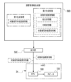
- FIG. 5 is a block diagram for explaining an example of processing contents of a sound collecting device side information acquisition unit, a target subject position information acquisition unit, a specific unit, and an adjustment sound information generation unit of the information processing device according to the embodiment.
- CPU refers to the abbreviation of "Central Processing Unit”.
- RAM is an abbreviation for "Random Access Memory”.
- DRAM refers to the abbreviation of "Dynamic Random Access Memory”.
- SRAM refers to the abbreviation of "Static Random Access Memory”.
- ROM is an abbreviation for "Read Only Memory”.
- SSD is an abbreviation for "Solid State Drive”.
- HDD refers to the abbreviation of "Hard Disk Drive”.
- EEPROM refers to the abbreviation of "Electrically Erasable and Programmable Read Only Memory”.
- I / F refers to the abbreviation of "Interface”.
- IC refers to the abbreviation of "Integrated Circuit”.
- ASIC refers to the abbreviation of "Application Special Integrated Circuit”.
- PLD refers to the abbreviation of "Programmable Logical Device”.
- FPGA refers to the abbreviation of "Field-Programmable Gate Array”.
- SoC refers to the abbreviation of "System-on-a-chip”.
- CMOS is an abbreviation for "Complementary Metal Oxide Semiconducor”.
- CCD refers to the abbreviation of "Charge Coupled Device”.
- EL refers to the abbreviation for "Electro-Luminescence”.
- GPU refers to the abbreviation of "Graphics Processing Unit”.
- LAN refers to the abbreviation of "Local Area Network”.
- 3D refers to the abbreviation of "3 Dimension”.
- USB refers to the abbreviation of "Universal Serial Bus”.
- HMD refers to the abbreviation of "Head Mounted Display”.
- fps refers to an abbreviation for "frame per second”.
- GPS is an abbreviation for "Global Positioning System”.
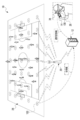
- the information processing system 10 includes an information processing device 12, a smartphone 14, a plurality of imaging devices 16, an imaging device 18, and a wireless communication base station (hereinafter, simply referred to as a “base station”) 20. And HMD34.
- the number of base stations 20 is not limited to one, and a plurality of base stations 20 may exist.
- the communication standards used in the base station 20 include a wireless communication standard including an LTE (Long Term Evolution) standard and a wireless communication standard including a WiFi (802.11) standard and / or a Bluetooth (registered trademark) standard. Is included.
- the imaging devices 16 and 18 are imaging devices having a CMOS image sensor, and are equipped with an optical zoom function and / or a digital zoom function. Instead of the CMOS image sensor, another type of image sensor such as a CCD image sensor may be adopted.
- CMOS image sensor another type of image sensor such as a CCD image sensor may be adopted.
- plural of image pickup devices when it is not necessary to distinguish between the image pickup device 18 and the plurality of image pickup devices 16, they are referred to as “plurality of image pickup devices” without reference numerals.
- the plurality of imaging devices 16 are installed in the soccer stadium 22. Each of the plurality of imaging devices 16 is arranged so as to surround the soccer field 24, and images are taken from a plurality of directions with a region including the soccer field 24 as an imaging region.
- an example in which each of the plurality of image pickup devices 16 is arranged so as to surround the soccer field 24 is given, but the technique of the present disclosure is not limited to this, and the arrangement of the plurality of image pickup devices 16 is not limited to this. It is determined according to the virtual viewpoint image to be generated.
- a plurality of image pickup devices 16 may be arranged so as to surround the entire soccer field 24, or a plurality of image pickup devices 16 may be arranged so as to surround a specific part thereof.
- the image pickup device 18 is installed in an unmanned aerial vehicle (for example, a multi-rotorcraft unmanned aerial vehicle), and takes a bird's-eye view of a region including a soccer field 24 as an imaging region from the sky.
- the imaging region in a state in which the region including the soccer field 24 is viewed from the sky refers to the imaging surface of the soccer field 24 by the imaging device 18.
- the information processing device 12 is installed in the control room 32.
- the plurality of imaging devices 16 and the information processing device 12 are connected via a LAN cable 30, and the information processing device 12 controls the plurality of imaging devices 16 and is imaged by each of the plurality of imaging devices 16. The image obtained by this is acquired.
- the connection using the wired communication method by the LAN cable 30 is illustrated here, the connection is not limited to this, and the connection using the wireless communication method may be used.
- the base station 20 transmits and receives various information to and from the information processing device 12, the smartphone 14, the HMD 34, and the unmanned aerial vehicle 27 via wireless communication. That is, the information processing device 12 is wirelessly connected to the smartphone 14, the HMD 34, and the unmanned aerial vehicle 27 via the base station 20.
- the information processing device 12 controls the unmanned aerial vehicle 27 by wirelessly communicating with the unmanned aerial vehicle 27 via the base station 20, and acquires an image obtained by being imaged by the imaging device 18 from the unmanned aerial vehicle 27. Or do.
- the information processing device 12 is a device corresponding to a server, and the smartphone 14 and the HMD 34 are devices corresponding to a client terminal for the information processing device 12.
- terminal devices when it is not necessary to distinguish between the smartphone 14 and the HMD 34, they are referred to as “terminal devices” without reference numerals.
- the information processing device 12 and the terminal device wirelessly communicate with each other via the base station 20, so that the terminal device requests the information processing device 12 to provide various services, and the information processing device 12 is the terminal device. Provide services to the terminal device in response to the request from.
- the information processing device 12 acquires a plurality of images from the plurality of imaging devices, and transmits the video generated based on the acquired plurality of images to the terminal device via the base station 20.
- the viewer 28 possesses a smartphone 14, and the HMD 34 is attached to the head of the viewer 28.
- the video transmitted from the information processing device 12 (hereinafter, also referred to as “delivered video”) is received by the terminal device, and the delivered video received by the terminal device is visually recognized by the viewer 28 through the terminal device.
- the soccer stadium 22 is provided with spectator seats 26 so as to surround the soccer field 24.
- the viewer 28 may visually recognize the delivered video at the spectator seat 26, or may visually recognize the delivered video at a place other than the spectator seat 26 (for example, at home, etc.), and the viewer 28 visually recognizes the delivered video.
- the location may be any location as long as it can wirelessly communicate with the information processing device 12.
- the viewer 28 is an example of a "person" according to the technique of the present disclosure.
- the HMD 34 includes a main body portion 11A, a mounting portion 13A, and a speaker 158.
- the HMD 34 is attached to the viewer 28.
- the main body 11A is located from the forehead to the front of the viewer 28, and the attachment portion 13A is located in the upper half of the head of the viewer 28.
- the speaker 158 is attached to the mounting portion 13A and is located on the left side of the viewer 28.
- the mounting portion 13A is a band-shaped member having a width of about several centimeters, and includes an inner ring 13A1 and an outer ring 15A1.
- the inner ring 13A1 is formed in an annular shape and is fixed in close contact with the upper half of the head of the viewer 28.
- the outer ring 15A1 is formed in a shape in which the occipital side of the viewer 28 is cut out. The outer ring 15A1 bends outward from the initial position or shrinks inward from the bent state toward the initial position according to the adjustment of the size of the inner ring 13A1.
- the main body 11A includes a protective frame 11A1, a computer 150, and a display 156.
- the computer 150 controls the entire HMD 34.
- the protective frame 11A1 is a transparent plate curved so as to cover the entire eyes of the viewer 28, and is formed of, for example, a translucent plastic.
- the display 156 includes a screen 156A and a projection unit 156B, and the projection unit 156B is controlled by the computer 150.
- the screen 156A is arranged inside the protective frame 11A1. Screen 156A is assigned to each of the eyes of viewer 28.
- the screen 156A is made of a transparent material like the protective frame 11A1. The viewer 28 visually recognizes the real space through the screen 156A and the protective frame 11A1. That is, the HMD 34 is a transmissive HMD.
- the screen 156A is located at a position facing the eyes of the viewer 28, and the distribution image is projected on the inner surface of the screen 156A (the surface on the viewer 28 side) by the projection unit 156B under the control of the computer 150. Since the projection unit 156B is a well-known device, detailed description thereof will be omitted, but a display element such as a liquid crystal display for displaying the distribution image and projection optics for projecting the distribution image displayed on the display element toward the inner surface of the screen 156A. A device having a system.
- the screen 156A is realized by using a half mirror that reflects the delivered image projected by the projection unit 156B and transmits the light in the real space.
- the projection unit 156B projects the delivered image on the inner surface of the screen 156A at a predetermined frame rate (for example, 60 fps).
- the delivered video is reflected on the inner surface of the screen 156A and is incident on the eyes of the viewer 28. As a result, the viewer 28 visually recognizes the delivered video.
- the half mirror is illustrated here as the screen 156A, the present invention is not limited to this, and the screen 156A itself may be used as a display element such as a liquid crystal.
- a retinal projection HMD that directly irradiates the retina of the viewer 28's eye with a laser may be adopted.
- the speaker 158 is connected to the computer 150 and outputs sound under the control of the computer 150. That is, under the control of the computer 150, the speaker 158 receives an electric signal indicating sound, converts the received electric signal into sound, and outputs the converted sound to display various information in an audible manner. Realize.
- the speaker 158 is integrated with the computer 150, but a separate headphone (including earphone) connected to the computer 150 by wire or wirelessly may be used to output sound.
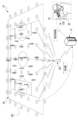
- the information processing apparatus 12 acquires a bird's-eye view image 46A showing an area including a soccer field 24 when observed from the sky from an unmanned aerial vehicle 27.
- the bird's-eye view image 46A is a moving image obtained by capturing a bird's-eye view of an area including a soccer field 24 as an imaging area (hereinafter, also simply referred to as an “imaging area”) by the imaging device 18 of the unmanned aerial vehicle 27. It is a statue.
- the captured image 46A is not limited to this, and is a still image showing a region including a soccer field 24 when observed from the sky. May be good.
- the information processing device 12 acquires a captured image 46B indicating an imaging region when observed from each position of the plurality of imaging devices 16 from each of the plurality of imaging devices 16.
- the captured image 46B is a moving image obtained by capturing an imaging region from a plurality of directions by each of the plurality of imaging devices 16.
- the captured image 46B is not limited to this, and the captured image 46B is a still image showing an imaging region when observed from each position of a plurality of imaging devices 16. It may be.
- the bird's-eye view image 46A and the captured image 46B are images obtained by capturing images in a plurality of directions in which regions including the soccer field 24 are different from each other, and are examples of "a plurality of images" according to the technique of the present disclosure.
- the information processing device 12 generates a virtual viewpoint image 46 by using the bird's-eye view image 46A and the captured image 46B.
- the virtual viewpoint image 46 is an image showing an imaging region when the imaging region is observed from a viewpoint position and a line-of-sight direction different from the viewpoint position and the line-of-sight direction of each of the plurality of imaging devices.
- the virtual viewpoint image 46 refers to a virtual viewpoint image showing an imaging area when the imaging area is observed from the viewpoint position 42 and the line-of-sight direction 44 in the spectator seat 26.
- An example of the virtual viewpoint image 46 is a moving image using a 3D polygon.
- a moving image is illustrated as the virtual viewpoint image 46, but the present invention is not limited to this, and a still image using 3D polygons may be used.
- the bird's-eye view image 46A obtained by being imaged by the image pickup apparatus 18 also shows a form example used for generating the virtual viewpoint image 46, but the technique of the present disclosure is not limited to this.
- the bird's-eye view image 46A is not used to generate the virtual viewpoint image 46, but only the plurality of captured images 46B obtained by being imaged by each of the plurality of imaging devices 16 are used to generate the virtual viewpoint image 46. You may do so.
- the virtual viewpoint image 46 is generated only from the image obtained by being imaged by the plurality of image pickup devices 16 without using the image obtained from the image pickup device 18 (for example, a multi-rotorcraft unmanned aerial vehicle). You may do so. If an image obtained from the image pickup device 18 (for example, a multi-rotorcraft unmanned aerial vehicle) is used, a more accurate virtual viewpoint image can be generated.
- the image pickup device 18 for example, a multi-rotorcraft unmanned aerial vehicle
- the information processing device 12 selectively transmits the bird's-eye view video 46A, the captured video 46B, and the virtual viewpoint video 46 as the distribution video to the terminal device.
- the information processing system 10 includes a plurality of sound collecting devices 100.
- the sound collecting device 100 collects sound.
- sound collection refers to sound capture, that is, sound collection.
- the sound collecting device 100 transmits sound information indicating the captured sound, that is, the collected sound.
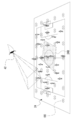
- the plurality of sound collecting devices 100 exist in the imaging region, and the installation positions of the plurality of sound collecting devices 100 are fixed in the imaging region.
- "existence" refers to, for example, existence in a state of being spaced in a regular arrangement.
- the meaning of "existence” in the technique of the present disclosure also includes the meaning of existence in a state of being scattered irregularly or regularly.
- a plurality of sound collecting devices 100 are scattered in the imaging region, but the plurality of sound collecting devices 100 do not necessarily have to be scattered in the imaging region, for example, without gaps. It may be aligned. Further, the plurality of sound collecting devices 100 do not necessarily exist in the imaging region.
- the plurality of sound collecting devices 100 are provided in the imaging region by a highly directional microphone from the outside of the imaging region. Sound may be picked up.
- sound is picked up by a plurality of sound collecting devices 100 existing in the imaging region and a plurality of sound collecting devices 100 existing outside the imaging region.
- the sound collecting device 100 does not exist in the imaging region, and a plurality of sound collecting devices 100C exist outside the imaging region, and a plurality of sound collecting devices having directivity in the imaging region. Sound is picked up in the imaging region by the device 100.
- the plurality of sound collecting devices 100 are embedded in the soccer field 24 in a matrix. Specifically, the sound collecting devices 100 are arranged at predetermined intervals (for example, at intervals of 5 meters) from one end to the other end of the side line and from one end to the other end of the goal line. In the example shown in FIG. 4A, 35 sound collecting devices 100 are arranged in a matrix in the soccer field 24, but the number of sound collecting devices 100 is not limited to this, and may be a plurality. Further, the plurality of sound collecting devices 100 do not need to be arranged in a matrix. For example, the plurality of sound collecting devices 100 may be arranged in a concentric circle, a spiral shape, or the like, and may be present in the soccer field 24.
- the plurality of sound collecting devices 100 are wirelessly connected to the information processing device 12 via the base station 20. Each of the plurality of sound collecting devices 100 exchanges various information with and from the information processing device 12 by performing wireless communication with the information processing device 12 via the base station 20. For example, each of the plurality of sound collecting devices 100 transmits sound information to the information processing device 12 in response to a request from the information processing device 12.
- the information processing device 12 generates adjustment sound information based on a plurality of sound information transmitted from the plurality of sound collecting devices 100.
- the adjusted sound information is information indicating the adjusted sound obtained by adjusting at least a part of the plurality of sounds indicated by the plurality of sound information.
- the information processing device 12 transmits the generated and obtained adjustment sound information to the HMD 34.
- the HMD 34 receives the adjustment sound information transmitted from the information processing apparatus 12, and outputs the adjustment sound indicated by the received adjustment sound information from the speaker 158.
- the information processing apparatus 12 includes a computer 50, a reception device 52, a display 53, a first communication I / F 54, and a second communication I / F 56.
- the computer 50 includes a CPU 58, a storage 60, and a memory 62, and the CPU 58, the storage 60, and the memory 62 are connected to each other via a bus line 64.
- a bus line 64 In the example shown in FIG. 5, for convenience of illustration, one bus line is shown as the bus line 64, but the bus line 64 includes a data bus, an address bus, a control bus, and the like.
- the CPU 58 controls the entire information processing device 12.
- the storage 60 stores various parameters and various programs.
- the storage 60 is a non-volatile storage device.
- a flash memory is adopted as an example of the storage 60, but the present invention is not limited to this, and may be EEPROM, HDD, SSD, or the like.
- the memory 62 is a volatile storage device. Various information is temporarily stored in the memory 62.
- the memory 62 is used as a work memory by the CPU 58.
- RAM is adopted as an example of the memory 62, but the present invention is not limited to this, and other types of volatile storage devices may be used.
- the reception device 52 receives instructions from the user or the like of the information processing device 12. Examples of the reception device 52 include a touch panel, hard keys, a mouse, and the like.
- the reception device 52 is connected to the bus line 64, and the instruction received by the reception device 52 is acquired by the CPU 58.
- the display 53 is connected to the bus line 64 and displays various information under the control of the CPU 58.
- An example of the display 53 is a liquid crystal display.
- another type of display such as an organic EL display or an inorganic EL display may be adopted as the display 53.
- the first communication I / F 54 is connected to the LAN cable 30.
- the first communication I / F 54 is realized by, for example, a device composed of circuits (for example, ASIC, FPGA, and / or PLD, etc.).
- the first communication I / F 54 is connected to the bus line 64 and controls the exchange of various information between the CPU 58 and the plurality of image pickup devices 16.
- the first communication I / F 54 controls a plurality of image pickup devices 16 according to the request of the CPU 58.
- the first communication I / F 54 acquires the captured image 46B (see FIG. 3) obtained by being imaged by each of the plurality of imaging devices 16, and outputs the acquired captured image 46B to the CPU 58.
- the second communication I / F 56 is connected to the base station 20 so as to be capable of wireless communication.
- the second communication I / F56 is realized by, for example, a device composed of circuits (for example, ASIC, FPGA, and / or PLD, etc.).
- the second communication I / F 56 is connected to the bus line 64.
- the second communication I / F 56 manages the exchange of various information between the CPU 58 and the unmanned aerial vehicle 27 in a wireless communication system via the base station 20. Further, the second communication I / F 56 manages the exchange of various information between the CPU 58 and the smartphone 14 in a wireless communication system via the base station 20.
- the second communication I / F 56 manages the exchange of various information between the CPU 58 and the HMD 34 in a wireless communication system via the base station 20. Further, the second communication I / F 56 manages the exchange of various information between the CPU 58 and each of the plurality of sound collecting devices 100 in a wireless communication system via the base station 20.
- the smartphone 14 includes a computer 70, a reception device 76, a display 78, a microphone 80, a speaker 82, an image pickup device 84, and a communication I / F 86.
- the computer 70 includes a CPU 88, a storage 90, and a memory 92, and the CPU 88, the storage 90, and the memory 92 are connected to each other via a bus line 94.
- one bus line is shown as the bus line 94 for convenience of illustration, but the bus line 94 may be composed of a serial bus, or may be a data bus, an address bus, and a bus line 94. It is configured to include a control bus and the like. Further, in the example shown in FIG.
- the CPU 88, the reception device 76, the display 78, the microphone 80, the speaker 82, the image pickup device 84, and the communication I / F86 are connected by a common bus, but the CPU 88 and each device are connected. It may be connected by a dedicated bus or a dedicated communication line.
- the CPU 88 controls the entire smartphone 14.
- the storage 90 stores various parameters and various programs.
- the storage 90 is a non-volatile storage device.
- EEPROM is adopted as an example of the storage 90, but the present invention is not limited to this, and a mask ROM, HDD, SSD, or the like may be used.
- Various information is temporarily stored in the memory 92, and the memory 92 is used as a work memory by the CPU 88.
- DRAM is adopted as an example of the memory 92, but the present invention is not limited to this, and other types of storage devices such as SRAM may be used.
- the reception device 76 receives instructions from the viewer 28. Examples of the reception device 76 include a touch panel 76A, a hard key, and the like. The reception device 76 is connected to the bus line 94, and the instruction received by the reception device 76 is acquired by the CPU 88.
- the display 78 is connected to the bus line 94 and displays various information under the control of the CPU 88.
- An example of the display 78 is a liquid crystal display.
- another type of display such as an organic EL display may be adopted as the display 78.
- the smartphone 14 is provided with a touch panel display, and the touch panel display is realized by the touch panel 76A and the display 78. That is, the touch panel display is formed by superimposing the touch panel 76A on the display area of the display 78. Further, in the present embodiment, the touch panel 28 is provided independently, but it may be built in the display 76A (so-called in-cell type touch panel).
- the microphone 80 collects sound (collects sound) and converts the collected sound into an electric signal.
- the microphone 80 is connected to the bus line 94.
- the electric signal obtained by converting the sound collected by the microphone 80 is acquired by the CPU 88 via the bus line 94.
- the speaker 82 converts an electric signal into sound.
- the speaker 82 is connected to the bus line 94.
- the speaker 82 receives the electric signal output from the CPU 88 via the bus line 94, converts the received electric signal into sound, and outputs the sound obtained by converting the electric signal to the outside of the smartphone 14.
- the image pickup device 84 acquires an image showing the subject by taking an image of the subject.
- the image pickup apparatus 84 is connected to the bus line 94.
- the image obtained by capturing the subject by the image pickup apparatus 84 is acquired by the CPU 88 via the bus line 94.
- the communication I / F86 is connected to the base station 20 so as to be capable of wireless communication.
- Communication I / F86 is realized, for example, by a device composed of circuits (eg, ASIC, FPGA, and / or PLD, etc.).
- the communication I / F86 is connected to the bus line 94.
- the communication I / F86 manages the exchange of various information between the CPU 88 and the external device in a wireless communication system via the base station 20.
- examples of the "external device" include an information processing device 12, an unmanned aerial vehicle 27, and an HMD 34.
- the HMD 34 is an example of a “display device” according to the technology of the present disclosure, and includes a computer 150, a reception device 152, a display 156, a microphone 157, a speaker 158, an eye tracker 166, and a communication I /. It is equipped with F168.
- the computer 150 includes a CPU 160, a storage 162, and a memory 164, and the CPU 160, the storage 162, and the memory 164 are connected via a bus line 170.
- a bus line 170 In the example shown in FIG. 7, one bus line is shown as the bus line 170 for convenience of illustration, but the bus line 170 includes a data bus, an address bus, a control bus, and the like.
- the CPU 160 controls the entire HMD 34.
- the storage 162 stores various parameters and various programs.
- the storage 162 is a non-volatile storage device.
- EEPROM is adopted as an example of the storage 162, but the present invention is not limited to this, and a mask ROM, HDD, SSD, or the like may be used.
- the memory 164 is a volatile storage device. Various information is temporarily stored in the memory 164, and the memory 164 is used as a work memory by the CPU 160.
- DRAM is adopted as an example of the memory 164, but the present invention is not limited to this, and other types of volatile storage devices such as SRAM may be used.
- the reception device 152 receives instructions from the viewer 28. Examples of the receiving device 152 include a remote controller and / or a hard key.
- the reception device 152 is connected to the bus line 170, and the instruction received by the reception device 152 is acquired by the CPU 160.
- the display 156 is a display capable of displaying the distribution video visually recognized by the viewer 28.
- the display 156 is connected to the bus line 170 and displays various information under the control of the CPU 160.
- the microphone 157 collects sound (collects sound) and converts the collected sound into sound information which is an electric signal.
- the microphone 157 is connected to the bus line 170.
- the sound information obtained by converting the sound collected by the microphone 157 is acquired by the CPU 160 via the bus line 170.
- the speaker 158 converts an electric signal into sound.
- the speaker 158 is connected to the bus line 170.
- the speaker 158 receives the electric signal output from the CPU 160 via the bus line 170, converts the received electric signal into sound, and outputs the sound obtained by converting the electric signal to the outside of the HMD 34.
- the eye tracker 166 includes an image sensor 166A.
- a CMOS image is adopted as the image sensor 166A.
- the image sensor 166A is not limited to the CMOS image sensor, and may be another type of image sensor such as a CCD image sensor.
- the eye tracker 166 uses the image sensor 166A to image both eyes of the viewer 28 according to a predetermined frame rate (for example, 60 fps).
- the eye tracker is based on an eye image (an image showing the eyes of the viewer 28) obtained by imaging both eyes of the viewer 28, and is also referred to as a line-of-sight direction of the viewer 28 (hereinafter, also simply referred to as “line-of-sight direction”). ) Is detected.
- the eye tracker 166 is a target subject image (hereinafter, also simply referred to as “target subject image”) indicating the target subject in the distributed video in a state where the distributed video (for example, the virtual viewpoint image 46) is displayed on the display 156.
- target subject image As the observation direction (hereinafter, also simply referred to as “observation direction”) of the viewer 28 who is observing the image, the line-of-sight direction is detected based on the image obtained by being imaged by the image sensor 166A.
- observation direction hereinafter, also simply referred to as “observation direction” of the viewer 28 who is observing the image
- the eye tracker 166 is an example of a "detector" according to the technique of the present disclosure.
- the communication I / F 168 is connected to the base station 20 so as to be capable of wireless communication.
- Communication I / F168 is realized, for example, by a device composed of circuits (eg, ASIC, FPGA, and / or PLD, etc.).
- the communication I / F 168 is connected to the bus line 170.
- the communication I / F 168 controls the exchange of various information between the CPU 160 and the external device in a wireless communication system via the base station 20.
- Examples of the "external device” include an information processing device 12, an unmanned aerial vehicle 27, a smartphone 14, and the like.
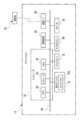
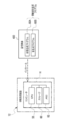
- the sound collecting device 100 includes a computer 200, a microphone 207, and a communication I / F 218.
- the computer 200 includes a CPU 210, a storage 212, and a memory 214, and the CPU 210, the storage 212, and the memory 214 are connected via a bus line 220.
- one bus line is shown as the bus line 220 for convenience of illustration, but the bus line 220 includes a data bus, an address bus, a control bus, and the like.
- the CPU 210 controls the entire sound collecting device 100.
- the storage 212 stores various parameters and various programs.
- the storage 212 is a non-volatile storage device.
- EEPROM is adopted as an example of the storage 212, but the present invention is not limited to this, and a mask ROM, HDD, SSD, or the like may be used.
- the memory 214 is a volatile storage device. Various types of information are temporarily stored in the memory 214, and the memory 214 is used as a work memory by the CPU 210.
- DRAM is adopted as an example of the memory 214, but the present invention is not limited to this, and other types of volatile storage devices such as SRAM may be used.
- the microphone 207 collects sound (collects sound) and converts the collected sound into an electric signal.
- the microphone 207 is connected to the bus line 220.
- the electric signal obtained by converting the sound collected by the microphone 207 is acquired by the CPU 210 via the bus line 220.
- the communication I / F 218 is connected to the base station 20 so as to be capable of wireless communication.
- Communication I / F218 is realized by, for example, a device composed of circuits (ASIC, FPGA, and / or PLD, etc.).
- the communication I / F 218 is connected to the bus line 220.
- the communication I / F 218 manages the exchange of various information between the CPU 210 and the information processing device 12 in a wireless communication system via the base station 20.
- the video generation program 60A and the sound generation program 60B are stored in the storage 60.
- information processing device programs when it is not necessary to distinguish between the video generation program 60A and the sound generation program 60B, they are referred to as "information processing device programs" without reference numerals.
- the CPU 58 is an example of the "processor” according to the technology of the present disclosure
- the memory 62 is an example of the “memory” according to the technology of the present disclosure.
- the CPU 58 reads the information processing device program from the storage 60, and expands the read information processing device program into the memory 62.
- the CPU 58 controls the entire information processing device 12 according to the information processing device program developed in the memory 62, and various information is provided between the plurality of imaging devices, the unmanned aerial vehicle 27, the terminal device, and the plurality of sound collecting devices 100. To give and receive.
- the CPU 58 reads the video generation program 60A from the storage 60, and expands the read video generation program 60A into the memory 62.
- the CPU 58 operates as the video generation unit 58A and the acquisition unit 58B according to the video generation program 60A expanded in the memory 62.
- the CPU 58 operates as the video generation unit 58A and the acquisition unit 58B to execute the video generation process (see FIG. 20) described later.
- the CPU 58 reads the sound generation program 60B from the storage 60, and expands the read sound generation program 60B into the memory 62.
- the CPU 58 operates as the acquisition unit 58B, the specific unit 58C, the adjustment sound information generation unit 58D, and the output unit 58E according to the sound generation program 60B expanded in the memory 62.
- the CPU 58 operates as an acquisition unit 58B, a specific unit 58C, an adjustment sound information generation unit 58D, and an output unit 58E to execute a sound generation process (see FIGS. 21 and 22) described later.
- the controlled sound information generation unit 58D is an example of the "generation unit" according to the technique of the present disclosure.
- the information processing device 12 transmits the bird's-eye view image 46A to the smartphone 14.
- the smartphone 14 receives the bird's-eye view image 46A transmitted from the information processing device 12.
- the bird's-eye view image 46A received by the smartphone 14 is displayed on the display 78 of the smartphone 14.
- the viewpoint instruction refers to an instruction of the position of a virtual viewpoint (hereinafter, referred to as “virtual viewpoint”) with respect to the imaging region.
- the line-of-sight instruction refers to an instruction in the direction of a virtual line-of-sight (hereinafter, referred to as “virtual line-of-sight”) with respect to the imaging region.
- the angle of view instruction refers to an instruction of the angle of view (hereinafter, simply referred to as “angle of view”) with respect to the imaging region.
- view-point line-of-sight angle-of-view instruction The position of the virtual viewpoint is also referred to as a “virtual viewpoint position”. Further, the direction of the "virtual line of sight” is also referred to as the "virtual line of sight direction”.
- a touch operation on the touch panel 76A can be mentioned. Instead of the touch operation, a tap operation or a double tap operation may be performed.
- Examples of the line-of-sight instruction include a slide operation on the touch panel 76A. Instead of the slide operation, a flick operation may be performed.
- Examples of the angle of view instruction include a pinch operation on the touch panel 76A. The pinch operation is roughly divided into a pinch-in operation and a pinch-out operation. The pinch-in operation is an operation performed when the angle of view is widened, and the pinch-out operation is an operation performed when the angle of view is narrowed.
- the viewpoint information indicating the virtual viewpoint position indicated by the viewpoint instruction, the line-of-sight direction information indicating the virtual line-of-sight direction instructed by the line-of-sight instruction, and the angle-of-view information indicating the angle of view indicated by the angle-of-view instruction are provided by the CPU 88 of the smartphone 14. It is transmitted to the information processing device 12.
- the term “view-view line-of-sight angle-of-view information” is used.
- the viewpoint line-of-sight angle of view information transmitted by the CPU 88 of the smartphone 14 is received by the image generation unit 58A, and the angle of view information transmitted by the CPU 88 of the smartphone 14 is received by the adjustment sound information generation unit 58D.
- the image generation unit 58A acquires the bird's-eye view image 46A from the unmanned aerial vehicle 27, and acquires the captured image 46B from each of the plurality of imaging devices 16.
- the first position association information is added to the bird's-eye view image 46A, and the second position association information is added to the captured image 46B.
- the first position association information is information indicating the correspondence between the position in the imaging region and the position in the bird's-eye view image 46A (for example, the position of the pixel).
- the position identification information in the imaging region for example, three-dimensional coordinates
- the position identification information in the bird's-eye view image that can specify the position in the bird's-eye view image 46A are provided. It is associated.
- the imaging region is a rectangular parallelepiped three-dimensional region with the soccer field 24 as the bottom surface, and the position identification information in the imaging region is one of the four corners of the soccer field 24. Is expressed in three-dimensional coordinates with the origin 24A as the origin.
- the second position association information is information indicating the correspondence between the position in the imaging region and the position of the captured image 46B (for example, the position of the pixel).
- the position identification information in the imaging region for example, three-dimensional coordinates
- the position identification information in the imaging image that can identify the position in the imaging image 46B are provided. It is associated.
- the image generation unit 58A generates a virtual viewpoint image 46 by using the bird's-eye view image 46A acquired from the unmanned aerial vehicle 27 and the captured image 46B acquired from each of the plurality of imaging devices 16 based on the line-of-sight angle of view information. ..
- Third position association information is added to the virtual viewpoint image 46.
- the third position association information is information indicating the correspondence relationship between the position in the imaging region and the position in the virtual viewpoint image 46 (for example, the position of the pixel), and is the information indicating the correspondence relationship of the "correspondence relationship information" according to the technique of the present disclosure. This is an example.
- the third position association information is generated by the video generation unit 58A based on the first position association information and the second position association information.
- the third position association information is an example of the "correspondence relationship information" related to the technique of the present disclosure, but in the image generation unit 58A, the virtual viewpoint image 46 is generated.
- the first position association information is an example of "correspondence-related information" according to the technique of the present disclosure.
- the second position association information corresponds to the technique of the present disclosure. This is an example of "relationship information”.
- the image generation unit 58A regenerates the virtual viewpoint image 46 with the change of the viewpoint information and the line-of-sight direction information.
- the third position association information is also based on the first position association information and the second position association information. Is regenerated by the image generation unit 58A. Then, the regenerated third position association information is given to the latest virtual viewpoint image 46 by the image generation unit 58A.
- the image generation unit 58A regenerates the virtual viewpoint image 46 with the change of the angle of view information.
- the third position association information is also generated based on the first position association information and the second position association information. Regenerated by part 58A. Then, the regenerated third position association information is given to the latest virtual viewpoint image 46 by the image generation unit 58A.
- the image generation unit 58A transmits the virtual viewpoint image 46 and the third position association information to the HMD 34.
- the CPU 160 receives the virtual viewpoint image 46 and the third position association information transmitted from the image generation unit 58A, and displays the received virtual viewpoint image 46 on the display 156.
- the image sensor 166A images the eye portion 29 of the viewer 28 while the virtual viewpoint image 46 is displayed on the display 156.
- the eye tracker 166 detects the observation direction based on the eye image obtained by imaging the eye 29 by the image sensor 166A, and outputs the observation direction identification information capable of specifying the detected observation direction to the CPU 160.
- the CPU 160 is used by the viewer 28 on the display 156 (specifically, the screen 156A shown in FIG. 2) based on the observation direction identification information and the position identification information in the virtual viewpoint image included in the third position association information.
- the position of focus (hereinafter referred to as "focused position") is specified. Then, the CPU 160 derives the target subject position information based on the specified focus position and the third position association information.
- the target subject position information includes subject position information in the imaging region and subject position information in the virtual viewpoint image.
- the subject position information in the imaging region is information indicating the position of the target subject in the imaging region (hereinafter, also referred to as “target subject position”).
- target subject position is information that can specify the position of the target subject image 47 in the virtual viewpoint image 46 (hereinafter, also referred to as “target subject image position”) (for example, an address that can specify the pixel position).
- target subject position information is information in which the subject position information in the imaging region and the subject position information in the virtual viewpoint image are associated with each other in a state where the correspondence between the target subject position and the target subject image position can be specified.
- the CPU 160 derives the target subject position information based on the third position association information and the detection result by the eye tracker 166, that is, the observation direction identification information. Specifically, the CPU 160 acquires the position identification information in the imaging region and the position identification information in the virtual viewpoint image corresponding to the focus position as the target subject position information from the third position association information. The CPU 160 transmits the acquired target subject position information to the information processing device 12.
- the acquisition unit 58B includes a target subject position information acquisition unit 58B1.
- the target subject position information acquisition unit 58B1 acquires the target subject position information.
- the target subject position information transmitted from the CPU 160 of the HMD 34 is acquired by being received by the target subject position information acquisition unit 58B1.
- the target subject position information acquisition unit 58B1 outputs the target subject position information to the video generation unit 58A.
- the image generation unit 58A generates the virtual viewpoint image 46 by using the bird's-eye view image 46A and the captured image 46B based on the viewpoint line-of-sight angle of view information and the target subject position information described above.
- the image generation unit 58A focuses on the target subject image position specified by the position identification information in the virtual viewpoint image included in the target subject position information input from the target subject position information acquisition unit 58B1.
- the virtual viewpoint image 46 is generated.
- the image generation unit 58A generates a virtual viewpoint image 46 that is in focus with respect to the target subject image 47 rather than the image around the target subject image 47.
- the state in which the target subject image 47 is in focus more than the image around the target subject image 47 means that the contrast value of the target subject image 47 is higher than the contrast value of the image around the target subject image 47. Refers to a high state.
- the virtual viewpoint image 46 includes an in-focus area where the target subject image 47 is located and a peripheral area of the target subject image 47, and the contrast value is lower than the in-focus area. It is roughly divided into areas.
- the target subject image 47 is an example of the “virtual viewpoint target subject image” according to the technique of the present disclosure.
- the virtual viewpoint image 46 having the in-focus area and the out-of-focus area is transmitted to the HMD 34 by the image generation unit 58A with the third position association information added.
- the CPU 160 receives the virtual viewpoint video 46 and the third position association information transmitted from the video generation unit 58A.
- the CPU 160 displays the received virtual viewpoint image 46 on the display 156.
- the acquisition unit 58B includes a sound collecting device side information acquisition unit 58B2 in addition to the target subject position information acquisition unit 58B1.
- the target subject position information acquisition unit 58B1 outputs the target subject position identification information acquired from the HMD 34 to the specific unit 58C.
- the sound collecting device 100 transmits sound information and sound collecting position specifying information indicating the position of the sound collecting device 100 in the imaging region (hereinafter, also referred to as “sound collecting device position”) to the information processing device 12.
- sound collecting position specifying information three-dimensional coordinates capable of specifying the sound collecting device position in the imaging region are adopted.
- the sound collecting position specifying information is an example of "sound collecting device position information" according to the technique of the present disclosure.
- the sound collecting device side information acquisition unit 58B2 acquires sound information and sound collecting position specifying information.
- the sound information and the sound collecting position specifying information transmitted from the sound collecting device 100 are acquired by being received by the sound collecting device side information acquisition unit 58B2.
- the sound collecting device side information acquisition unit 58B2 generates sound collecting device information based on the sound information acquired from the sound collecting device 100 and the sound collecting position specifying information.
- the sound collecting device information is information in which sound information and sound collecting position specifying information are associated with each sound collecting device 100.
- the sound collecting device side information acquisition unit 58B2 outputs the generated sound collecting device information to the specific unit 58C.
- the specific unit 58C acquires the target subject position information from the target subject position information acquisition unit 58B1 and acquires the sound collection device information from the sound collection device side information acquisition unit 58B2. Then, the specifying unit 58C identifies the target sound in the region corresponding to the target subject from the plurality of sound information based on the target subject position information and the sound collecting device information.
- the specific unit 58C acquires sound collecting device information for each of the plurality of sound collecting devices 100 from the sound collecting device side information acquisition unit 58B2. That is, the specific unit 58C acquires a plurality of sound collecting device information from the sound collecting device side information acquisition unit 58B2.
- the specifying unit 58C identifies the sound collecting device information having the sound collecting position specifying information corresponding to the subject position information in the imaging region included in the target subject position information from the plurality of sound collecting device information.
- the sound collecting position specifying information corresponding to the subject position information in the imaging area is the imaging area among a plurality of sound collecting device positions indicated by the plurality of sound collecting position specifying information included in the plurality of sound collecting device information. It refers to the sound collecting position specifying information that can specify the sound collecting device position closest to the target subject position specified from the internal subject position information.
- the specifying unit 58C specifies the sound information included in the specified sound collecting device information as the target sound information indicating the target sound in the region corresponding to the target subject position.
- the adjustment sound information generation unit 58D acquires the target sound information specified by the specific unit 58C from the specific unit 58C, and obtains the sound pickup device information for each of the plurality of sound collection devices 100 from the sound collection device side information acquisition unit 58B2. get.
- the adjustment sound information generation unit 58D generates the adjustment sound information based on the acquired target sound information and the sound collecting device information.
- the adjusted sound information is roughly classified into comprehensive sound information and target subject emphasis sound information.
- Comprehensive sound information is an example of "comprehensive sound information” and "whole sound information” according to the technology of the present disclosure.
- Comprehensive sound information refers to information indicating comprehensive sound.
- Comprehensive sound is an example of "comprehensive sound” and "whole sound” according to the technique of the present disclosure.
- the total sound refers to a sound obtained by integrating a plurality of sounds obtained by each of the plurality of sound collecting devices 100.
- the target subject emphasis sound information refers to information indicating a sound (hereinafter, also referred to as "target subject emphasis sound”) including a target sound (hereinafter, also referred to as "emphatic target sound”) emphasized rather than an ambient sound.
- the ambient sound refers to a sound emitted from a region different from the region corresponding to the target subject position indicated by the subject position information in the imaging region included in the target subject position information acquired by the specific unit 58C.
- the area corresponding to the target subject position refers to, for example, the target subject itself.
- the area corresponding to the target subject position may be a three-dimensional area defined by a predetermined distance from the target subject position.
- a three-dimensional region defined by a predetermined distance from the target subject position for example, a spherical region within a radius of 3 meters centered on the target subject position, or a 4 meter square cube centered on the target subject position. The radial region is mentioned.
- the emphasis target sound makes the volume of the ambient sound lower than the volume of the sound indicated by the sound information related to the ambient sound, or makes the volume of the target sound louder than the volume of the target sound indicated by the target sound information. It is realized by. Not limited to this, the emphasis target sound makes the volume of the ambient sound lower than the volume of the sound indicated by the sound information related to the ambient sound, and the volume of the target sound is the target sound indicated by the target sound information. It may be realized by making it louder than the volume of.
- the controlled sound information generation unit 58D selectively executes the first generation process and the second generation process.
- the first generation process is a process for generating target subject emphasis sound information
- the second generation process is a process for generating comprehensive sound information.
- the adjusted sound information generation unit 58D selectively executes the first generation process and the second generation process based on the angle of view information acquired from the smartphone 14.
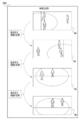
- the adjustment sound information generation unit 58D executes the first generation process when the angle of view indicated by the angle of view information is less than the reference angle of view, and the angle of view indicated by the angle of view information is The second generation process is executed when the angle of view is equal to or larger than the reference angle of view.
- the angle of view indicated by the angle of view information is “ ⁇ ” and the reference angle of view is “ ⁇ th ”
- “adjustment sound information is generated when the angle of view ⁇ ⁇ reference angle of view ⁇ th ”.
- the target subject emphasis sound information is generated by executing the first generation process by the unit 58D.
- the adjustment sound information generation unit 58D performs the second generation process. Comprehensive sound information is generated by executing.
- the target subject emphasis sound may cause discomfort to the viewer 28. Therefore, here, a sensory test is performed as a lower limit value of the angle of view that does not cause discomfort to the viewer 28 when the total sound is output from the speaker 158 than when the target subject emphasis sound is output from the speaker 158. And / or a fixed value derived in advance by computer simulation or the like is adopted as the reference angle of view ⁇ th .
- the reference angle theta th a modifiable variable value according to the instructions received by the receiving device 52, 76 or 152 May be adopted as.
- the CPU 58 (see FIG. 9) operates as an output unit 58E capable of outputting target subject emphasis sound information generated by the adjustment sound information generation unit 58D.
- the output unit 58E acquires the target subject emphasis sound information from the adjustment sound information generation unit 58D when the target subject emphasis sound information is generated by executing the first generation process, and the acquired target subject emphasis sound information. Is output. That is, the output unit 58E transmits the target subject emphasis sound information to the HMD 34. Further, when the total sound information is generated by executing the second generation process, the output unit 58E acquires the total sound information from the adjustment sound information generation unit 58D and outputs the acquired total sound information. That is, the output unit 58E transmits the comprehensive sound information to the HMD 34.
- the output unit 58E outputs the target subject emphasis sound information and the total sound information in synchronization with the output of the virtual viewpoint image 46 to the HMD 34 by the image generation unit 58A.
- the image generation unit 58A outputs the synchronization signal to the output unit 58E at the timing when the output of the virtual viewpoint image 46 is started.
- the output unit 58E outputs the target subject emphasis sound information and the total sound information in accordance with the input of the synchronization signal from the image generation unit 58A.
- the target subject emphasis sound information transmitted from the output unit 58E is received by the CPU 160, and the target subject emphasis sound indicated by the received target subject emphasis sound information is output from the speaker 158. Further, in the HMD 34, the total sound information transmitted from the output unit 58E is received by the CPU 160, and the total sound indicated by the received total sound information is output from the speaker 158.
- step ST10 the image generation unit 58A acquires the bird's-eye view image 46A, the captured image 46B, and the viewpoint line-of-sight angle of view information, and then the image generation process shifts to step ST12. ..
- step ST12 the image generation unit 58A uses the bird's-eye view image 46A and the captured image 46B acquired in step ST10 based on the viewpoint line-of-sight angle of view information acquired in step ST10, thereby focusing on a virtual viewpoint at infinity.
- the video 46 is generated, and then the video generation process proceeds to step ST14.
- step ST14 the video generation unit 58A outputs the virtual viewpoint video 46 generated in step ST12 to the HMD 34, and then the video generation process shifts to step ST16.
- the virtual viewpoint image 46 output to the HMD 34 by executing the process of step ST14 is displayed on the display 156 in the HMD 34 and is visually recognized by the viewer 28.
- step ST16 the target subject position information acquisition unit 58B1 acquires the target subject position information derived by the CPU 160 based on the detection result of the eye tracker 166, and then the image generation process shifts to step ST18.
- step ST18 the image generation unit 58A acquires the bird's-eye view image 46A, the captured image 46B, and the viewpoint line-of-sight angle of view information, and then the image generation process shifts to step ST20.
- step ST20 the image generation unit 58A uses the bird's-eye view image 46A and the captured image 46B acquired in step ST18 based on the viewpoint line-of-sight angle of view information acquired in step ST18 and the target subject position information acquired in step ST16. A virtual viewpoint image 46 that is in focus with respect to the target subject image 47 is generated, and then the image generation process proceeds to step ST22.
- step ST22 the video generation unit 58A outputs the virtual viewpoint video 46 generated in step ST20 to the HMD 34, and then the video generation process shifts to step ST24.
- the virtual viewpoint image 46 output to the HMD 34 by executing the process of step ST22 is displayed on the display 156 in the HMD 34 and is visually recognized by the viewer 28.
- step ST24 the CPU 58 determines whether or not the condition for ending the video generation process (video generation process end condition) is satisfied.
- the video generation processing end condition there is a condition that the reception device 52, 76 or 152 has received an instruction to end the video generation process. If the video generation processing end condition is not satisfied in step ST24, the determination is denied and the video generation processing proceeds to step ST16. If the video generation process end condition is satisfied in step ST24, the determination is affirmed and the video generation process ends.
- step ST50 the sound collecting device side information acquisition unit 58B2 acquires sound information and sound collecting position specifying information from each of the plurality of sound collecting devices 100, and then generates sound. The process proceeds to step ST52.
- step ST52 the sound collecting device side information acquisition unit 58B2 generates sound collecting device information for each of the plurality of sound collecting devices 100 based on the sound information and the sound collecting position specifying information acquired in step ST50, and then generates sound collecting device information. , The sound generation process proceeds to step ST54.
- step ST54 the adjustment sound information generation unit 58D acquires the angle of view information from the smartphone 14, and then the sound generation process shifts to step ST56.
- step ST56 the adjustment sound information generation unit 58D determines whether or not the angle of view indicated by the angle of view information acquired in step ST54 is less than the reference angle of view. In step ST56, if the angle of view indicated by the angle of view information acquired in step ST54 is equal to or greater than the reference angle of view, the determination is denied and the sound generation process proceeds to step ST58 shown in FIG. In step ST56, if the angle of view indicated by the angle of view information acquired in step ST54 is less than the reference angle of view, the determination is affirmed and the sound generation process proceeds to step ST64.
- step ST58 shown in FIG. 22 the adjustment sound information generation unit 58D generates comprehensive sound information based on the sound collecting device information generated in step ST52, and then the sound generation process shifts to step ST60.
- step ST60 the output unit 58E determines whether or not a synchronization signal has been input from the video generation unit 58A. If the synchronization signal is not input from the video generation unit 58A in step ST60, the determination is denied and the determination in step ST60 is performed again. When a synchronization signal is input from the video generation unit 58A in step ST60, the determination is affirmed, and the sound generation process proceeds to step ST62.
- step ST62 the output unit 58E outputs the total sound information generated in step ST58 to the HMD 34, and then the sound generation process shifts to step ST74 shown in FIG.
- the total sound indicated by the total sound information output to the HMD 34 by executing the process of step ST62 is output from the speaker 158 in the HMD 34 and heard by the viewer 28.
- step ST64 shown in FIG. 21 the target subject position information acquisition unit 58B1 acquires the target subject position information from the HMD 34, and then the sound generation process shifts to step ST66.
- step ST66 the specifying unit 58C identifies the target sound information based on the sound collecting device information generated in step ST52 and the target subject position information acquired in step ST64, and then the sound generation process is performed in step. Move to ST68.
- step ST68 the adjustment sound information generation unit 58D generates target subject emphasis sound information based on the sound collecting device information generated in step ST50 and the target sound information specified in step ST66, and then the sound. The generation process proceeds to step ST70.
- step ST70 the output unit 58E determines whether or not a synchronization signal has been input from the video generation unit 58A. If the synchronization signal is not input from the video generation unit 58A in step ST70, the determination is denied and the determination in step ST70 is performed again. When a synchronization signal is input from the video generation unit 58A in step ST70, the determination is affirmed, and the sound generation process shifts to step ST72.
- step ST72 the output unit 58E outputs the target subject emphasis sound information generated in step ST68 to the HMD34, and then the sound generation process shifts to step ST74.
- the target subject emphasis sound indicated by the target subject emphasis sound information output to the HMD 34 by executing the process of step ST72 is output from the speaker 158 in the HMD 34 and is heard by the viewer 28.
- step ST74 the CPU 58 determines whether or not the condition for ending the sound generation process (sound generation process end condition) is satisfied.
- the sound generation processing end condition there is a condition that the reception device 52, 76 or 152 has received an instruction to end the sound generation process. If the condition for ending the sound generation process is not satisfied in step ST74, the determination is denied and the sound generation process proceeds to step ST50. If the sound generation process end condition is satisfied in step ST74, the determination is affirmed and the sound generation process ends.
- the target subject position information acquisition unit 58B1 acquires the target subject position information from the HMD 34, and the sound collection device side information acquisition unit 58B2 obtains the sound information and the sound collection position identification information. Obtained from each of the plurality of sound collecting devices 100. Further, the specific unit 58C specifies the target sound in the region corresponding to the target subject position from the plurality of sound information based on the sound collection position identification information and the target subject position information. Then, when the virtual viewpoint image 46 is generated, the target subject emphasis sound information is generated by the adjustment sound information generation unit 58D.
- the target subject emphasis sound information is information indicating the target subject emphasis sound.
- the target subject emphasis sound emphasizes the target sound more than the sound (peripheral sound) emitted from an area different from the area corresponding to the target subject position indicated by the target subject position information acquired by the target subject position information acquisition unit 58B1. It is a sound including the emphasized sound to be emphasized. Therefore, it is possible to contribute to the hearing by the viewer 28 of the sound emitted from the region corresponding to the position of the target subject indicated by the generated virtual viewpoint image 46.
- the first generation process and the second generation process are selectively executed by the adjustment sound information generation unit 58D.
- the target subject emphasis sound information is generated
- the comprehensive sound information is generated. Therefore, the target subject emphasis sound information and the total sound information can be selectively generated.
- the first generation process is executed when the angle of view indicated by the angle of view information is less than the reference angle of view
- the second generation process is executed when the angle of view indicated by the angle of view information is equal to or greater than the reference angle of view. The generation process is executed. Therefore, the target subject emphasis sound information and the total sound information can be selectively generated according to the angle of view.
- the eye tracker 166 detects the observation direction of the viewer 28 who is observing the virtual viewpoint image 46 while the virtual viewpoint image 46 is displayed on the display 156 of the HMD 34.
- the CPU 160 generates the target subject position information based on the third position association information and the detection result of the eye tracker 166, and the generated target subject position information is acquired by the target subject position information acquisition unit 58B1. Will be done.
- the target subject position information acquired by the target subject position information acquisition unit 58B1 is used to identify the target sound information by the specific unit 58C, and the target sound information specified by the specific unit 58C is the target sound information generation unit 58D. Used to generate subject emphasis sound information. Therefore, it is possible to prevent the information indicating the sound emitted from the position irrelevant to the observation direction of the viewer 28 from being erroneously generated as the target subject emphasis sound information.
- the line-of-sight direction of the viewer 28 is detected as an observation direction by the eye tracker 166 based on the eye image obtained by imaging the eye portion 29 of the viewer 28 by the image sensor 166A.
- the observation direction can be detected with higher accuracy than when a direction different from the line-of-sight direction of the viewer 28 is detected as the observation direction.
- the HMD 34 is attached to the viewer 28, and the HMD 34 is provided with the eye tracker 166. Therefore, as compared with the case where the eye tracker 166 is not provided on the HMD 34, the observation direction in the state where the HMD 34 is attached to the viewer 28 can be detected with higher accuracy.
- the target subject image is an image in the virtual viewpoint image 46 that is more in focus than the image around the target subject image. Therefore, the position where the target subject emphasis sound is emitted can be specified from the virtual viewpoint image 46.
- the information processing device 12 a plurality of sound collecting devices 100 are fixed in the imaging region. Therefore, the sound collecting position specifying information can be easily acquired as compared with the case where the plurality of sound collecting devices 100 move.
- the target subject position information acquisition unit 58B1 has been described with reference to a form example in which the target subject position information is acquired based on the detection result of the eye tracker 166, but the technique of the present disclosure is not limited to this.
- the target subject position information may be acquired by the target subject position information acquisition unit 58B1 based on the instruction received by the reception device 52, 76 or 152.
- the distributed video here, as an example, the virtual viewpoint video 46
- the instruction information indicating the position of the target subject image in the distributed video is the reception device 52, 76 or 152. Accepted by.
- the target subject position information acquisition unit 58B1 acquires the target subject position information based on the third position association information and the instruction information received by the reception device 52, 76 or 152. That is, the target subject position information acquisition unit 58B1 derives the target subject position identification information in the imaging region corresponding to the target subject image position instructed by the instruction information as the target subject position information from the third position association information. Get location information.
- the reception device 52, 76 or 152 is an example of the "reception device (acceptor)" according to the technique of the present disclosure.
- the technique of the present disclosure is not limited to this.
- observation direction change frequency the frequency at which the observation direction of the viewer 28 changes per unit time
- the adjustment sound information generation unit 58D may selectively execute the first generation process and the second generation process according to the frequency of change in the observation direction.
- the CPU 160 is based on the observation direction identification information, as shown in FIG. 23 as an example.
- the frequency of change in the observation direction (for example, N times / sec) is calculated.
- the CPU 160 outputs observation direction change frequency information indicating the calculated frequency to the accommodation sound information generation unit 58D.
- the adjustment sound information generation unit 58D executes the first generation process or the second generation process with reference to the observation direction change frequency information.
- the second generation process is executed without executing the first generation process. Further, when the observation direction change frequency is less than the predetermined frequency, the first generation process is executed without executing the second generation process.
- the target subject emphasis sound is output from the speaker 158 when the observation direction is not determined, the target subject emphasis sound may cause discomfort to the viewer 28. Therefore, here, as the lower limit value of the observation direction change frequency in which the total sound is output from the speaker 158 rather than the target subject emphasis sound is output from the speaker 158, the viewer 28 is not uncomfortable. Fixed values derived in advance by sensory tests and / or computer simulations are adopted as the default frequency.
- a variable value that can be changed according to the instruction received by the receiving device 52, 76 or 152 may be adopted as the default frequency.
- the sound generation process executed by the CPU 160 is the sound shown in FIG. Compared with the generation process, it is different in that it has step ST100 instead of step ST54 and that it has step ST102 instead of step ST56.
- step ST100 the adjustment sound information generation unit 58D acquires the observation direction change frequency information from the HMD 34, and then the sound generation process shifts to step ST102.
- step ST102 the adjustment sound information generation unit 58D determines whether or not the observation direction change frequency indicated by the observation direction change frequency information acquired in step ST100 is less than the predetermined frequency. In step ST102, if the observation direction change frequency indicated by the observation direction change frequency information acquired in step ST100 is equal to or higher than the predetermined frequency, the determination is denied and the sound generation process proceeds to step ST58 shown in FIG. In step ST102, if the observation direction change frequency indicated by the observation direction change frequency information acquired in step ST100 is less than the predetermined frequency, the determination is affirmed and the sound generation process proceeds to step ST64.
- the discomfort given to the viewer 28 due to the frequent switching of the target subject emphasis sound is reduced as compared with the case where the target subject emphasis sound is also switched as the target subject is frequently changed. be able to.
- the sound generation process shifts to step ST58 shown in FIG. 22, but the technique of the present disclosure is not limited to this.
- the sound generation process may shift to step ST58 shown in FIG. ..
- the sound generation process shifts to step ST64, but the technique of the present disclosure is not limited to this.
- the sound generation process may shift to step ST58 shown in FIG. ..
- the technique of the present disclosure is not limited to this.
- the target subject emphasis sound information may be generated, and the generated target subject emphasis sound information may not be output by the output unit 58E.
- the target subject emphasis sound is not output from the speaker 158, the viewer is caused by the frequent switching of the target subject emphasis sound as compared with the case where the target subject emphasis sound is also switched as the target subject changes frequently. The discomfort given to 28 can be reduced.
- the target subject emphasis sound information when the angle of view indicated by the angle of view information is equal to or larger than the reference angle of view, the target subject emphasis sound information is not generated, but the technique of the present disclosure is not limited to this. ..
- the target subject emphasis sound information when the angle of view indicated by the angle of view information is equal to or greater than the reference angle of view, the target subject emphasis sound information may be generated, and the generated target subject emphasis sound information may not be output by the output unit 58E.
- the adjustment sound information generation unit 58D may generate stepwise emphasis sound information by executing the second generation process.
- the stepwise emphasis sound information is information including comprehensive sound information, intermediate sound information, and target subject emphasis sound information.
- the intermediate sound information is information indicating an intermediate sound in which the target subject sound is emphasized more than the total sound and suppressed more than the target subject emphasized sound.
- the output unit 58E uses the total sound information, the intermediate sound information, and the target subject emphasis sound information generated by the adjustment sound information generation unit 58D as the total sound information.
- the intermediate sound information and the target subject emphasis sound information are output to the HMD 34 in this order.
- the sound generation process executed by the CPU 58 has a step 150 instead of the step ST58 and a step 152 instead of the step ST62, as compared with the sound generation process shown in FIG. Is different.
- step ST150 shown in FIG. 26 the stepwise emphasis sound information is generated by the adjustment sound information generation unit 58D, and in step ST152, the stepwise emphasis sound information generated in step ST150 is output to the HMD 34 by the output unit 58E.
- the total sound information, the intermediate sound information, and the target subject emphasis sound information are output to the HMD 34 from the speaker 158 in the order of the total sound, the intermediate sound, and the target subject emphasis sound, and are heard by the viewer 28.
- the discomfort given to the viewer 28 due to the frequent switching of the target subject emphasis sound is reduced as compared with the case where the target subject emphasis sound is also switched as the target subject is frequently changed. be able to.
- the intermediate sound information may be information including a plurality of sound information subdivided so that the volume is gradually increased in a stepless or multi-step manner.
- the target subject emphasis sound information information indicating the emphasis sound including the emphasis target sound is adopted, but the target subject emphasis sound information includes the emphasis target sound and also includes the peripheral sound. It may be information indicating no sound. As a result, it is possible to contribute to easier listening of the target sound as compared with the case where the target subject emphasis sound information is information indicating a sound including peripheral sounds in addition to the emphasized target sound.
- HMD34 is exemplified, but the technique of the present disclosure is not limited to this.
- the target subject by the target subject position information acquisition unit 58B1 based on the detection result by the eye tracker 166 provided in the specific HMD34 among the plurality of HMD34s and the third position association information.
- the position information may be acquired.
- the HMD 34 is attached to each of the viewers 28A to 28Z (hereinafter, when it is not necessary to distinguish between them, they are simply referred to as “viewers” without reference numerals).
- the target subject position information acquisition unit 58B1 obtains the target subject position information based on the detection result by the eye tracker 166 provided in the HMD 34 mounted on any of the viewers 28A to 28Z and the third position association information. get. According to this configuration, it is possible to generate target subject emphasis sound information corresponding to a target subject of interest to a viewer wearing a specific HMD34 among a plurality of HMD34s.
- the sound collecting device 300 may be attached to the target subject 47A.
- the sound collecting device 300 includes a computer 302, a GPS receiver 304, a microphone 306, a communication I / F 308, and a bus line 316.
- the computer 302 includes a CPU 310, a storage 312, and a memory 314.
- one bus line is shown as the bus line 316 for convenience of illustration, but the bus line 316 is similar to the bus lines 64, 94 and 170 described in the above embodiment. Includes a data bus, an address bus, a control bus, and the like.
- the computer 302 corresponds to the computer 200 shown in FIG.
- the microphone 306 corresponds to the microphone 207 shown in FIG.
- the communication I / F 308 corresponds to the communication I / F 218 shown in FIG.
- the CPU 310 corresponds to the CPU 210 shown in FIG.
- the storage 312 corresponds to the storage 212 shown in FIG.
- the memory 314 corresponds to the memory 214 shown in FIG.
- the GPS receiver 304 receives radio waves from a plurality of GPS satellites (not shown) in response to an instruction from the CPU 310, and outputs reception result information indicating the reception result to the CPU 310.
- the CPU 310 calculates GPS information indicating latitude, longitude, and altitude based on the reception result information input from the GPS receiver 304.
- the CPU 310 wirelessly communicates with the information processing device 12 via the base station 20 to transmit the sound information obtained from the microphone 306 to the information processing device 12, and also uses GPS information as sound collection position identification information. It is transmitted to the processing device 12. As a result, the position of the target subject 47A in the imaging region, that is, the target subject position is specified by the information processing apparatus 12.
- GPS information is used as sound collecting position specifying information
- the technique of the present disclosure is not limited to this, and information capable of specifying the position of the sound collecting device 300 in the imaging region. Any information may be used as long as it is. Further, a plurality of sound collecting devices 300 may be attached to the target subject 47A.
- the target sound can be easily obtained as compared with the case where the sound collecting device 300 is not attached to the target subject 47A.
- the sound collecting device 300 may be attached to each of a plurality of persons (for example, a player and / or a referee in the soccer field 24) who can be a target subject existing in the imaging region. According to this configuration, it is possible to easily obtain the target sound even if the target subject is switched between the plurality of people, as compared with the case where the sound collecting device 300 is not attached to each of the plurality of people in the imaging region. it can.
- a plurality of sound collecting devices 300 are fixed in the imaging region as described above, but the sound collecting devices 300 and sound collecting devices attached to each of the plurality of persons have been described.
- the device 300 may be used in combination.
- the sound information obtained by the sound collecting device 100 is used by the information processing device 12 without changing the volume, but the technique of the present disclosure is not limited to this.
- the volume may be made different among a plurality of sounds indicated by the plurality of sound information obtained by the plurality of sound collecting devices 100.
- the specific unit 58C uses the sound collection position identification information acquired by the sound collection device side information acquisition unit 58B2 and the target subject position information acquired by the target subject position information acquisition unit 58B1 to obtain the target subject.
- the positional relationship between the position and the plurality of sound collecting devices 100 is specified.
- the adjustment sound information generation unit 58D adjusts the sound indicated by the sound information to be smaller as the sound at a position farther from the target subject position, as shown in FIG. 29 as an example, according to the positional relationship specified by the specific unit 58C.
- the sound information is controlled so that the sound is produced.
- the sound information controlled in this way is used, for example, by the adjustment sound information generation unit 58D to generate the target subject emphasis sound information and the total sound information. According to this configuration, even in a state where the target sound and the peripheral sound are mixed, it is possible to contribute to the distinguishable hearing of the target sound and the peripheral sound.
- the volume of the sound indicated by the sound information is linearly attenuated with respect to the distance from the target subject position to the sound collecting device 100, but the present invention is not limited to this.
- the volume of the sound indicated by the sound information may be attenuated non-linearly with respect to the distance from the target subject position to the sound collecting device 100.
- the volume of the sound indicated by the sound information may be attenuated in a stepwise manner. When the volume is attenuated in a stepwise manner, the time interval of the same volume may be gradually shortened or lengthened.
- the first generation process is executed when the angle of view indicated by the angle of view information is less than the reference angle of view
- the second generation is performed when the angle of view indicated by the angle of view information is equal to or greater than the reference angle of view.
- the technique of the present disclosure is not limited to this.
- the second generation process is executed when the field of view when observing the imaging area from the viewpoint position 42 is a field of view surrounding the preset reference area 24B in the soccer field 24. You may.
- the first generation process may be executed when the field of view when the imaging area is observed from the viewpoint position 42 is within the reference area 24B.
- the visual field surrounds the reference region 24B by displaying an image showing the entire reference region 24B in the virtual viewpoint image 46 generated by the image generation unit 58A. It may be done by determining whether or not it is included by the CPU 58.
- the second generation process may be executed without executing the first generation process. ..
- a rectangular region is adopted as the reference region 24B, but the shape of the reference region 24B is not limited to this, and is a circular region or a polygon other than a rectangle. It may be a region of another shape such as a region of shape.
- the CPU 58 of the information processing device 12 executes the image generation processing and the sound generation processing (hereinafter, when it is not necessary to distinguish between them, it is referred to as “information processing device side processing”).
- information processing device side processing the technique of the present disclosure is not limited to this, and the processing on the information processing device side may be executed by the terminal device or distributed by a plurality of devices such as the smartphone 14 and the HMD 34. It may be executed.
- the HMD 34 may be made to execute the processing on the information processing device side.
- the information processing device program is stored in the storage 162 of the HMD 34.
- the CPU 160 executes the video generation process by operating as the video generation unit 58A and the acquisition unit 58B according to the video generation program 60A. Further, the CPU 160 executes the sound generation process by operating as the acquisition unit 58B, the specific unit 58C, the adjustment sound information generation unit 58D, and the output unit 58E according to the sound generation program 60B.
- the HMD34 has been exemplified, but the technique of the present disclosure is not limited to this, and various devices with an arithmetic unit such as a smartphone, a tablet terminal, a head-up display, or a personal computer can be substituted. It is possible to do.
- the soccer field 22 is illustrated, but this is only an example, and is a baseball field, a rugby field, a curling field, an athletic field, a swimming pool, a concert hall, an outdoor music field, and a theater venue.
- the place may be any place.
- the wireless communication method using the base station 20 is illustrated, but this is only an example, and the technique of the present disclosure is established even in the wired communication method using a cable.
- the unmanned aerial vehicle 27 is illustrated, but the technique of the present disclosure is not limited to this, and the image pickup device 18 suspended by a wire (for example, a self-propelled image pickup device that can move along the wire). ) May be used to image the imaging region.
- a wire for example, a self-propelled image pickup device that can move along the wire.
- computers 50, 70, 100, 150, 200 and 302 have been exemplified, but the technique of the present disclosure is not limited to this.
- computers 50, 70, 100, 150, 200 and / or 302 devices including ASICs, FPGAs, and / or PLDs may be applied.
- computers 50, 70, 100, 150, 200 and / or 302 a combination of hardware configuration and software configuration may be used.
- the information processing device program is stored in the storage 60, but the technique of the present disclosure is not limited to this, and as shown in FIG. 34 as an example, an SSD or SSD which is a non-temporary storage medium or
- the information processing device program may be stored in an arbitrary portable storage medium 400 such as a USB memory.
- the information processing device program stored in the storage medium 400 is installed in the computer 50, and the CPU 58 executes the processing on the information processing device side according to the information processing device program.
- the information processing device program is stored in a storage unit of another computer or server device connected to the computer 50 via a communication network (not shown), and the information processing device is requested by the information processing device 12.
- the program may be downloaded to the information processing device 12.
- the processing on the information processing device side based on the downloaded information processing device program is executed by the CPU 58 of the computer 50.
- the CPU 58 is illustrated, but the technique of the present disclosure is not limited to this, and a GPU may be adopted. Further, a plurality of CPUs may be adopted instead of the CPU 58. That is, the information processing device side processing may be executed by one processor or a plurality of physically separated processors. Further, instead of the CPUs 88, 160, 210 and / or 310, a GPU may be adopted, or a plurality of CPUs may be adopted, or by one processor or a plurality of physically separated processors. Various processes may be executed.
- processors can be used as hardware resources for executing processing on the information processing device side.
- the processor include, as described above, software, that is, a CPU, which is a general-purpose processor that functions as a hardware resource for executing processing on the information processing apparatus side according to a program.
- a dedicated electric circuit which is a processor having a circuit configuration specially designed for executing a specific process such as FPGA, PLD, or ASIC can be mentioned.
- a memory is built in or connected to each processor, and each processor executes processing on the information processing device side by using the memory.
- the hardware resource that executes the processing on the information processing device side may be composed of one of these various processors, or a combination of two or more processors of the same type or different types (for example, a combination of a plurality of FPGAs). , Or a combination of CPU and FPGA). Further, the hardware resource for executing the processing on the information processing device side may be one processor.
- one processor is configured by a combination of one or more CPUs and software, and this processor performs information processing.
- a hardware resource that executes device-side processing.
- SoC and the like there is a form in which a processor that realizes the functions of the entire system including a plurality of hardware resources that execute processing on the information processing device side with one IC chip is used.
- the processing on the information processing apparatus side is realized by using one or more of the above-mentioned various processors as a hardware resource.
- a and / or B is synonymous with "at least one of A and B". That is, “A and / or B” means that it may be only A, only B, or a combination of A and B. Further, in the present specification, when three or more matters are connected and expressed by "and / or", the same concept as “A and / or B" is applied.
- Appendix 1 With the processor Includes memory built into or connected to the processor The above processor A plurality of sound information indicating the sound obtained by each of the plurality of sound collecting devices scattered in the imaging region, sound collecting device position information indicating the position of each of the plurality of sound collecting devices in the imaging region, and Acquires the target subject position information indicating the position of the target subject in the above imaging region, and obtains the target subject position information. Based on the acquired sound collecting device position information and the target subject position information, the target sound in the region corresponding to the position of the target subject is specified from the plurality of sound information.
- the viewpoint position information indicating the position of the virtual viewpoint with respect to the imaging region
- the line-of-sight direction information indicating the direction of the virtual line of sight with respect to the imaging region
- the image angle information indicating the angle of view with respect to the imaging region
- the target subject position information is the acquired target.
Landscapes
- Engineering & Computer Science (AREA)
- Signal Processing (AREA)
- Physics & Mathematics (AREA)
- Multimedia (AREA)
- Acoustics & Sound (AREA)
- Otolaryngology (AREA)
- Health & Medical Sciences (AREA)
- Theoretical Computer Science (AREA)
- General Health & Medical Sciences (AREA)
- Computer Graphics (AREA)
- General Physics & Mathematics (AREA)
- Geometry (AREA)
- Computing Systems (AREA)
- Computer Hardware Design (AREA)
- General Engineering & Computer Science (AREA)
- Software Systems (AREA)
- Studio Devices (AREA)
- Image Generation (AREA)
- Circuit For Audible Band Transducer (AREA)
- Processing Or Creating Images (AREA)
- Stereophonic System (AREA)
Priority Applications (3)
| Application Number | Priority Date | Filing Date | Title |
|---|---|---|---|
| JP2021536932A JP7317119B2 (ja) | 2019-07-26 | 2020-07-16 | 情報処理装置、情報処理方法、及びプログラム |
| US17/647,602 US12058512B2 (en) | 2019-07-26 | 2022-01-11 | Information processing apparatus, information processing method, and program |
| US18/764,296 US20240365078A1 (en) | 2019-07-26 | 2024-07-04 | Information processing apparatus, information processing method, and program |
Applications Claiming Priority (2)
| Application Number | Priority Date | Filing Date | Title |
|---|---|---|---|
| JP2019-138236 | 2019-07-26 | ||
| JP2019138236 | 2019-07-26 |
Related Child Applications (1)
| Application Number | Title | Priority Date | Filing Date |
|---|---|---|---|
| US17/647,602 Continuation US12058512B2 (en) | 2019-07-26 | 2022-01-11 | Information processing apparatus, information processing method, and program |
Publications (1)
| Publication Number | Publication Date |
|---|---|
| WO2021020150A1 true WO2021020150A1 (ja) | 2021-02-04 |
Family
ID=74229632
Family Applications (1)
| Application Number | Title | Priority Date | Filing Date |
|---|---|---|---|
| PCT/JP2020/027696 Ceased WO2021020150A1 (ja) | 2019-07-26 | 2020-07-16 | 情報処理装置、情報処理方法、及びプログラム |
Country Status (3)
| Country | Link |
|---|---|
| US (2) | US12058512B2 (https=) |
| JP (1) | JP7317119B2 (https=) |
| WO (1) | WO2021020150A1 (https=) |
Families Citing this family (1)
| Publication number | Priority date | Publication date | Assignee | Title |
|---|---|---|---|---|
| CN115002401B (zh) * | 2022-08-03 | 2023-02-10 | 广州迈聆信息科技有限公司 | 一种信息处理方法、电子设备、会议系统及介质 |
Citations (5)
| Publication number | Priority date | Publication date | Assignee | Title |
|---|---|---|---|---|
| JP2017229011A (ja) * | 2016-06-24 | 2017-12-28 | 日本電信電話株式会社 | ミキシング装置、その方法、プログラム、及び記録媒体 |
| JP2018019294A (ja) * | 2016-07-28 | 2018-02-01 | キヤノン株式会社 | 情報処理システム及びその制御方法、コンピュータプログラム |
| JP2018106297A (ja) * | 2016-12-22 | 2018-07-05 | キヤノンマーケティングジャパン株式会社 | 複合現実感提示システム、及び、情報処理装置とその制御方法、並びに、プログラム |
| JP2019057059A (ja) * | 2017-09-20 | 2019-04-11 | 富士ゼロックス株式会社 | 情報処理装置、情報処理システム及びプログラム |
| WO2019093155A1 (ja) * | 2017-11-10 | 2019-05-16 | ソニー株式会社 | 情報処理装置、および情報処理方法、並びにプログラム |
Family Cites Families (4)
| Publication number | Priority date | Publication date | Assignee | Title |
|---|---|---|---|---|
| US9693009B2 (en) * | 2014-09-12 | 2017-06-27 | International Business Machines Corporation | Sound source selection for aural interest |
| US10235010B2 (en) | 2016-07-28 | 2019-03-19 | Canon Kabushiki Kaisha | Information processing apparatus configured to generate an audio signal corresponding to a virtual viewpoint image, information processing system, information processing method, and non-transitory computer-readable storage medium |
| WO2019160955A1 (en) * | 2018-02-13 | 2019-08-22 | SentiAR, Inc. | Augmented reality display sharing |
| US11057720B1 (en) * | 2018-06-06 | 2021-07-06 | Cochlear Limited | Remote microphone devices for auditory prostheses |
-
2020
- 2020-07-16 JP JP2021536932A patent/JP7317119B2/ja active Active
- 2020-07-16 WO PCT/JP2020/027696 patent/WO2021020150A1/ja not_active Ceased
-
2022
- 2022-01-11 US US17/647,602 patent/US12058512B2/en active Active
-
2024
- 2024-07-04 US US18/764,296 patent/US20240365078A1/en active Pending
Patent Citations (5)
| Publication number | Priority date | Publication date | Assignee | Title |
|---|---|---|---|---|
| JP2017229011A (ja) * | 2016-06-24 | 2017-12-28 | 日本電信電話株式会社 | ミキシング装置、その方法、プログラム、及び記録媒体 |
| JP2018019294A (ja) * | 2016-07-28 | 2018-02-01 | キヤノン株式会社 | 情報処理システム及びその制御方法、コンピュータプログラム |
| JP2018106297A (ja) * | 2016-12-22 | 2018-07-05 | キヤノンマーケティングジャパン株式会社 | 複合現実感提示システム、及び、情報処理装置とその制御方法、並びに、プログラム |
| JP2019057059A (ja) * | 2017-09-20 | 2019-04-11 | 富士ゼロックス株式会社 | 情報処理装置、情報処理システム及びプログラム |
| WO2019093155A1 (ja) * | 2017-11-10 | 2019-05-16 | ソニー株式会社 | 情報処理装置、および情報処理方法、並びにプログラム |
Also Published As
| Publication number | Publication date |
|---|---|
| US20240365078A1 (en) | 2024-10-31 |
| US12058512B2 (en) | 2024-08-06 |
| US20220132261A1 (en) | 2022-04-28 |
| JPWO2021020150A1 (https=) | 2021-02-04 |
| JP7317119B2 (ja) | 2023-07-28 |
Similar Documents
| Publication | Publication Date | Title |
|---|---|---|
| US9858643B2 (en) | Image generating device, image generating method, and program | |
| JP5228307B2 (ja) | 表示装置、表示方法 | |
| WO2016009864A1 (ja) | 情報処理装置、表示装置、情報処理方法、プログラム、および情報処理システム | |
| JP2015149634A (ja) | 画像表示装置および方法 | |
| CN104301664A (zh) | 指向性控制系统、指向性控制方法、收音系统及收音控制方法 | |
| JP2014017776A (ja) | 画像生成装置および画像生成方法 | |
| US20220109822A1 (en) | Multi-sensor camera systems, devices, and methods for providing image pan, tilt, and zoom functionality | |
| JP7163498B2 (ja) | 表示制御装置、表示制御方法、及びプログラム | |
| JP6292658B2 (ja) | 頭部装着型映像表示システム及び方法、頭部装着型映像表示プログラム | |
| JP2025098206A (ja) | 情報処理装置、情報処理装置の作動方法、及びプログラム | |
| EP4325476A1 (en) | Video display system, information processing method, and program | |
| JP2016140078A (ja) | 画像生成装置および画像生成方法 | |
| WO2019142432A1 (ja) | 情報処理装置、情報処理方法及び記録媒体 | |
| US20240365078A1 (en) | Information processing apparatus, information processing method, and program | |
| JP2023123484A (ja) | 情報処理装置、情報処理方法、及びプログラム | |
| US20200167948A1 (en) | Control system, method of performing analysis and storage medium | |
| JP5971298B2 (ja) | 表示装置、表示方法 | |
| JP2013083994A (ja) | 表示装置、表示方法 | |
| JP7467612B2 (ja) | 画像処理装置、画像処理方法、及びプログラム | |
| JP6600186B2 (ja) | 情報処理装置、制御方法およびプログラム | |
| JP2018157314A (ja) | 情報処理システム、情報処理方法及びプログラム | |
| JP2018112991A (ja) | 画像処理装置、画像処理システム、画像処理方法、及びプログラム | |
| WO2020054585A1 (ja) | 情報処理装置、情報処理方法及びプログラム | |
| JP5653771B2 (ja) | 映像表示機器及びプログラム | |
| WO2024116270A1 (ja) | 携帯情報端末及び仮想現実表示システム |
Legal Events
| Date | Code | Title | Description |
|---|---|---|---|
| 121 | Ep: the epo has been informed by wipo that ep was designated in this application |
Ref document number: 20847840 Country of ref document: EP Kind code of ref document: A1 |
|
| ENP | Entry into the national phase |
Ref document number: 2021536932 Country of ref document: JP Kind code of ref document: A |
|
| NENP | Non-entry into the national phase |
Ref country code: DE |
|
| 122 | Ep: pct application non-entry in european phase |
Ref document number: 20847840 Country of ref document: EP Kind code of ref document: A1 |