WO2021014989A1 - Heat insulating protective member, method for manufacturing same, method for installing same, in-furnace member, and heating furnace - Google Patents
Heat insulating protective member, method for manufacturing same, method for installing same, in-furnace member, and heating furnace Download PDFInfo
- Publication number
- WO2021014989A1 WO2021014989A1 PCT/JP2020/026892 JP2020026892W WO2021014989A1 WO 2021014989 A1 WO2021014989 A1 WO 2021014989A1 JP 2020026892 W JP2020026892 W JP 2020026892W WO 2021014989 A1 WO2021014989 A1 WO 2021014989A1
- Authority
- WO
- WIPO (PCT)
- Prior art keywords
- heat insulating
- insulating protective
- protective member
- peripheral surface
- inorganic
- Prior art date
Links
Images


Classifications
-
- F—MECHANICAL ENGINEERING; LIGHTING; HEATING; WEAPONS; BLASTING
- F27—FURNACES; KILNS; OVENS; RETORTS
- F27D—DETAILS OR ACCESSORIES OF FURNACES, KILNS, OVENS, OR RETORTS, IN SO FAR AS THEY ARE OF KINDS OCCURRING IN MORE THAN ONE KIND OF FURNACE
- F27D1/00—Casings; Linings; Walls; Roofs
- F27D1/04—Casings; Linings; Walls; Roofs characterised by the form, e.g. shape of the bricks or blocks used
- F27D1/045—Bricks for lining cylindrical bodies, e.g. skids, tubes
-
- F—MECHANICAL ENGINEERING; LIGHTING; HEATING; WEAPONS; BLASTING
- F16—ENGINEERING ELEMENTS AND UNITS; GENERAL MEASURES FOR PRODUCING AND MAINTAINING EFFECTIVE FUNCTIONING OF MACHINES OR INSTALLATIONS; THERMAL INSULATION IN GENERAL
- F16L—PIPES; JOINTS OR FITTINGS FOR PIPES; SUPPORTS FOR PIPES, CABLES OR PROTECTIVE TUBING; MEANS FOR THERMAL INSULATION IN GENERAL
- F16L59/00—Thermal insulation in general
- F16L59/02—Shape or form of insulating materials, with or without coverings integral with the insulating materials
- F16L59/021—Shape or form of insulating materials, with or without coverings integral with the insulating materials comprising a single piece or sleeve, e.g. split sleeve, two half sleeves
- F16L59/024—Shape or form of insulating materials, with or without coverings integral with the insulating materials comprising a single piece or sleeve, e.g. split sleeve, two half sleeves composed of two half sleeves
-
- F—MECHANICAL ENGINEERING; LIGHTING; HEATING; WEAPONS; BLASTING
- F27—FURNACES; KILNS; OVENS; RETORTS
- F27D—DETAILS OR ACCESSORIES OF FURNACES, KILNS, OVENS, OR RETORTS, IN SO FAR AS THEY ARE OF KINDS OCCURRING IN MORE THAN ONE KIND OF FURNACE
- F27D1/00—Casings; Linings; Walls; Roofs
- F27D1/0003—Linings or walls
- F27D1/0006—Linings or walls formed from bricks or layers with a particular composition or specific characteristics
- F27D1/0009—Comprising ceramic fibre elements
- F27D1/002—Comprising ceramic fibre elements the fibre elements being composed of adjacent separate strips
-
- F—MECHANICAL ENGINEERING; LIGHTING; HEATING; WEAPONS; BLASTING
- F27—FURNACES; KILNS; OVENS; RETORTS
- F27D—DETAILS OR ACCESSORIES OF FURNACES, KILNS, OVENS, OR RETORTS, IN SO FAR AS THEY ARE OF KINDS OCCURRING IN MORE THAN ONE KIND OF FURNACE
- F27D1/00—Casings; Linings; Walls; Roofs
- F27D1/0003—Linings or walls
- F27D1/0033—Linings or walls comprising heat shields, e.g. heat shieldsd
-
- F—MECHANICAL ENGINEERING; LIGHTING; HEATING; WEAPONS; BLASTING
- F27—FURNACES; KILNS; OVENS; RETORTS
- F27D—DETAILS OR ACCESSORIES OF FURNACES, KILNS, OVENS, OR RETORTS, IN SO FAR AS THEY ARE OF KINDS OCCURRING IN MORE THAN ONE KIND OF FURNACE
- F27D1/00—Casings; Linings; Walls; Roofs
- F27D1/14—Supports for linings
- F27D1/145—Assembling elements
-
- F—MECHANICAL ENGINEERING; LIGHTING; HEATING; WEAPONS; BLASTING
- F27—FURNACES; KILNS; OVENS; RETORTS
- F27D—DETAILS OR ACCESSORIES OF FURNACES, KILNS, OVENS, OR RETORTS, IN SO FAR AS THEY ARE OF KINDS OCCURRING IN MORE THAN ONE KIND OF FURNACE
- F27D3/00—Charging; Discharging; Manipulation of charge
- F27D3/02—Skids or tracks for heavy objects
- F27D3/022—Skids
- F27D3/024—Details of skids, e.g. riders
-
- C—CHEMISTRY; METALLURGY
- C21—METALLURGY OF IRON
- C21D—MODIFYING THE PHYSICAL STRUCTURE OF FERROUS METALS; GENERAL DEVICES FOR HEAT TREATMENT OF FERROUS OR NON-FERROUS METALS OR ALLOYS; MAKING METAL MALLEABLE, e.g. BY DECARBURISATION OR TEMPERING
- C21D1/00—General methods or devices for heat treatment, e.g. annealing, hardening, quenching or tempering
Definitions
- the present invention relates to a heat insulating protective member attached to a skid pipe or the like in a heating furnace, a construction method thereof, and a heating furnace.
- Inorganic fiber aggregates and inorganic fiber molded bodies with high thermal shock resistance are used as protective members for skid pipes in the heating furnace of the steel industry (Patent Documents 1 to 3).
- Patent Document 1 describes that the skid pipe is covered with a ring-shaped heat insulating material made of ceramic fiber produced by punching.
- the present invention comprises an inorganic fiber molded body having cushioning properties and excellent workability, a heat insulating protective member having excellent physical strength, a method for manufacturing and constructing the heat insulating protective member, a member in a furnace, and a heating furnace. And aims to provide.
- the present invention focuses on improving the rigidity of the outer peripheral surface side of a hollow cylindrical heat insulating protective member used in a high temperature environment such as in a furnace without impairing the cushioning property on the inner peripheral surface side. It proposes a heat insulating protective member that is less likely to be damaged by.
- the gist of the present invention is as follows.
- a heat insulating protective member made of an inorganic fiber molded body having a hollow cylindrical shape or a hollow cylindrical divided shape the inorganic fiber molded body has an inner peripheral surface (c) facing the hollow and an outer peripheral surface constituting the outer periphery.
- the intermediate point between the outer peripheral surface (a) and the inner peripheral surface (c) of the inorganic fiber molded body is set as an intermediate portion (b), and the bulk density (Da) on the outer peripheral surface and the intermediate portion.
- the inorganic fiber molded body is an inorganic fiber molded body containing inorganic binder particles that bond inorganic fibers to each other, and is characterized in that the number of the inorganic binder particles is larger toward the outer peripheral surface (a) side.
- the heat insulating protective member according to any one of [1] to [3].
- the heat insulating protection member is the heat insulating protective member of [6], and is a member in a furnace in which pins are inserted into the holes of both adjacent heat insulating protective members having their end faces abutted against each other.
- a method for constructing a heat insulating protective member which comprises a step of mounting the heat insulating protective member according to any one of [1] to [6] on the outer surface of the inner surface of the furnace.
- the heat insulating protection member is the heat insulating protective member of [6], and the method of constructing the heat insulating protective member of [10] in which pins are inserted into the holes of both adjacent heat insulating protective members whose end faces are butted against each other.
- a method for manufacturing a heat insulating protective member which comprises a step of sucking in a direction toward the direction to remove an inorganic binder-containing liquid and a step of drying the hollow cylindrical molded product.
- the inner mold and the outer mold are arranged in a suction / dehydration case, and the inner mold and the outer mold have a large number of holes penetrating in a direction orthogonal to the axis of the inner mold.
- the heat insulating protective member of the present invention is impregnated with an inorganic binder and contains a large amount of the inorganic binder on the outer peripheral surface side rather than the inner peripheral surface side thereof, so that the bulk density on the outer peripheral surface side is high.
- the inorganic binder enhances the integral bondability of the heat insulating protective member, and the rigidity of the outer peripheral surface is improved without impairing the cushioning property of the inner peripheral surface.
- the heat insulating protective member of the present invention is an inorganic fiber molded body, and has more inorganic binder particles on the outer peripheral surface than the inner peripheral surface, which is a firing product of the inorganic binder, and has a high bulk density on the outer peripheral surface side. Therefore, the inorganic binder particles enhance the integral bondability of the heat insulating protective member, and the rigidity of the outer peripheral surface is improved without impairing the cushioning property of the inner peripheral surface.
- FIG. 12a is a perspective view showing a method of constructing the heat insulating protective member according to the embodiment
- FIG. 12b is a sectional view taken along line XIb-XIb of FIG. 12a.
- the heat insulating protective member is attached to the skid pipe, but it may be attached to other in-core members such as a skid beam.
- a to b indicating the numerical range means “a or more and b or less”, and also means “preferably larger than a” and “preferably smaller than b”. It includes.
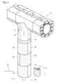
- the skid pipe 1 to which the heat insulating protective member is installed has a pipe shape made of heat-resistant steel and is erected from the hearth G of the heat treatment furnace.
- the skid beam 2 is installed so as to be supported by a plurality of skid pipes 1.
- the upper part of the skid pipe 1 is provided with a fireproof coating 3 made of a fireproof castable.
- a heat insulating protective member is installed under the fireproof coating 3 of the skid pipe 1.
- the skid pipe 1 is provided with a plurality of anchors (not shown) at intervals in the height direction.
- the cross section of the skid pipe 1 may not be perfectly circular, it is preferable to cover the outer peripheral surface of the skid pipe 1 with the base layer 5 (see FIG. 12b) prior to the construction of the heat insulating protective member. As a result, the adhesion between the outer peripheral surface and the heat insulating protective member 10 is improved, and a higher heat insulating effect can be exhibited.
- the base layer 5 is made of an inorganic fiber, a castable refractory, or the like.
- a plurality of heat insulating protective members 10 made of needle blankets of inorganic fibers (alumina / silica fibers in this embodiment) are attached to the skid pipe 1 in multiple stages above and below.
- the heat insulating protection member 10 has a hollow cylindrical shape that is approximately half-split, and is mounted so as to sandwich the skid pipe 1 between a pair of heat insulating protective members 10.
- a refractory (alumina in this embodiment) pin 12 is inserted into a hole 11 on the upper end surface of the heat insulating protective member 10. Insert and stand.
- a pair of heat insulating protective members 10 which are the second steps from the bottom are attached to the skid pipe 1.
- the pin 12 protruding from the lower heat insulating protection member 10 is inserted into the hole 11 on the lower end surface of the second stage heat insulating protective member 10. Further, the pin 12 is inserted into the hole 11 on the upper end surface of the second-stage heat insulating protective member 10 to stand.
- the third and subsequent stages of heat insulating protective member 10 are mounted on the skid pipe 1 in the same manner.
- the directions of the heat insulating protective members 10 are changed one step at a time. Is preferable.
- a paste-like heat-resistant adhesive composition may be attached to the abutting surface between the heat insulating protective members 10 or the inner peripheral surface of the heat insulating protective member 10.
- a pulverized inorganic fiber and a refractory clay such as kaolinite are preferably kneaded with water.
- the undried blanket 15 impregnated with the inorganic binder is wrapped around the outer peripheral surface of each heat insulating protective member 10 as shown in FIGS. 12a and 12b, and the construction is completed.
- the undried blanket 15 impregnated with the inorganic binder is dried and fired by undergoing a temperature raising / heating step after the start of operation of the heating furnace to become a blanket containing an oxide-based refractory composition.
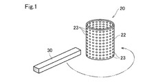
- a bottomed hollow cylindrical inner mold 20 having a bottom surface portion 21 and a side peripheral portion 22 is prepared.
- the side peripheral portion 22 is provided with a large number of holes 23 penetrating from the inner peripheral surface to the outer peripheral surface.
- the bottom surface 21 is not provided with a hole.
- a mold release sheet (not shown) made of a glass fiber sheet or the like is wound around the outer peripheral surface of the inner mold 20, and then a needle blanket 30 of inorganic fibers (alumina fibers in this embodiment) is placed between the inner mold and the outer mold. Laminate and fill.
- the size and shape of the needle blanket are not particularly limited, but it is preferable to process the needle blanket according to the size of the heat insulating protective member (the length from the inner peripheral surface side to the outer peripheral surface side and the length of the inner peripheral surface).
- a first outer mold 40 surrounding the inner mold 20 is arranged, and a needle is placed between the side peripheral portion 42 of the outer mold 40 and the side peripheral portion 22 of the inner mold 20.
- the needle blanket 30 is filled by pushing in the blanket 30.
- the outer mold 40 has a bottomed hollow cylindrical shape having a bottom surface portion 41 and a side peripheral portion 42.
- the inner mold 20 is coaxially arranged in the outer mold 40 so that the bottom surface portion 21 overlaps the bottom surface portion 41.
- the side peripheral portion 42 is provided with a large number of holes 43 that penetrate.
- a flange 44 is provided at the upper end of the side peripheral portion 42.
- the height of the outer mold 40 is preferably lower than that of the inner mold 20. In this embodiment, the height of the outer mold 40 is about half that of the inner mold 20.
- the second outer mold 50 is arranged on the upper side of the outer mold 40.
- the second outer mold 50 has a hollow cylindrical shape and has the same diameter as the outer mold 40.
- the outer mold 50 is also provided with a large number of holes 53.
- the outer mold 50 is provided with flanges 54 and 55 at the lower end and the upper end, respectively.
- the outer molds 40 and 50 are integrated by overlapping their flanges 44 and 54 and connecting them with bolts.
- the needle blanket 30 is similarly filled between the inner mold 20 and the outer mold 50 between the second outer mold 50 and the inner mold 20.
- the ring plate 61 of the pushing jig 60 is pushed between the inner mold 20 and the second outer mold 50, and the inner mold 20 is pushed.
- the needle blanket 30 wound between the outer molds 40 and 50 is compressed to form a hollow cylindrical molded body 30A in which the needle blanket 30 is integrated in a series. Note that this compression may be performed by screwing the bolt 62 described below.
- the jig 60 has a ring plate 61 and a lid plate 63. There is an opening 64 in the central portion of the lid plate 63.
- the lid plate 63 and the upper flange 55 of the second outer mold 50 are connected by bolts (not shown) or the like, and the ring plate 61 is pressed by the bolts 62 to maintain the compressed state of the hollow cylindrical molded body 30A.
- the entire integral 80 of the inner mold 20, the hollow cylindrical molded body 30A, the outer molds 40, 50, and the jig 60 is immersed in the inorganic binder-containing liquid L in the tank 81, and the inorganic binder is used.
- the hollow cylindrical molded body 30A is sufficiently impregnated with the containing liquid.
- the integral 80 is pulled up from the inorganic binder-containing liquid L and placed in the suction / dehydration case 70 as shown in FIG.
- the peripheral edge of the lid plate 63 is placed on the flange at the upper end of the case 70 via the packing 74.
- the inside of the case 70 is absorbed through the suction port 75 at the bottom of the case 70.
- the inorganic binder-containing liquid L accumulated in the inner mold 20 passes through the holes 23 of the inner mold 20, the hollow cylindrical molded body 30A, and the holes 43, 53 of the outer molds 40, 50, and the outer molds 40, 50. It is sucked out and discharged through the suction port 75. At this time, air flows into the inner mold 20 through the opening 64.
- the opening 64 is connected to a warm air source (not shown) to continue suction. As a result, the warm air passes through the hollow cylindrical molded body 30A and the hollow cylindrical molded body 30A is dried.
- the inner mold 20 is removed from the hollow cylindrical molded body 30A to obtain the hollow cylindrical molded body 30A shown in FIG.
- Holes 11 are bored in the upper end surface and the lower end surface of the hollow cylindrical molded body 30A.
- the drilling method is not particularly limited, but for example, it is preferable to use a cork borer from the viewpoint of dimensional accuracy.
- the hollow cylindrical molded body 30A is cut in the direction parallel to the cylinder axis core line to obtain a half-split hollow cylindrical heat insulating protective member 10.
- the cut surface 10c is oblique with respect to the diameter direction of the hollow cylindrical molded body 30A.
- the heat insulating protective member 10 manufactured in this manner is generally shipped in the manufactured form and mounted on a structure inside a furnace such as a skid pipe.
- the heat insulating protective member manufactured as described above may be further fired, allowed to cool, and then shipped as a heat insulating protective member product.
- the axial length of the cylinder is preferably 100 to 600 mm, particularly 150 to 400 mm, and the thickness is preferably 20 to 100 mm, particularly about 30 to 80 mm.
- the inorganic binder is impregnated in the entire heat insulating protective member 10 as shown in FIGS. 5 and 6.
- the inorganic binder-containing liquid is sucked from the inner mold 20 toward the outer molds 40 and 50. Therefore, in the hollow cylindrical molded body 30A of FIG. 7, the inorganic binder is contained toward the outer peripheral surface side. The amount will be large.
- the inorganic binder has the effect of forming inorganic binder particles and binding the fibers to each other when the heat insulating protective member 10 is fired. Therefore, the higher the content of the inorganic binder, the larger the amount of the inorganic binder particles adhering to the heat insulating protective member 10 after firing, and the higher the rigidity of the outer peripheral surface of the heat insulating protective member 10, that is, the higher the physical strength.
- the content of the inorganic binder is large, the weight of the heat insulating protective member 10 increases.
- the content of the inorganic binder on the outer peripheral surface side of the heat insulating protective member 10 is large, the strength and rigidity of the heat insulating protective member 10 on the outer peripheral surface side are high.
- the content of the inorganic binder inorganic binder is small, so that the bulk density of the heat insulating protective member 10 becomes small.
- the needle blanket 30 for manufacturing the heat insulating protective member 10 is not particularly limited as long as it is an inorganic fiber blanket, but is preferably an inorganic fiber needle blanket described later.
- this needle blanket is obtained by subjecting a fiber aggregate of inorganic fibers, which does not contain fibers having a fiber diameter of 3 ⁇ m or less, to a needling treatment.
- a needle blanket By using such a needle blanket, the wind corrosion resistance of the heat insulating protective member for a skid pipe of the present invention can be enhanced.
- the inorganic fibers constituting the needle blanket are not particularly limited, and examples thereof include silica, alumina / silica, and zirconia, spinel, titania, and calcia containing them, or composite fibers, but heat resistance is particularly preferable.
- Alumina / silica-based fibers, particularly polycrystalline alumina / silica-based fibers, are used in terms of fiber strength (toughness) and safety.
- composition ratio (mass ratio) of alumina / silica of the alumina / silica-based fiber is preferably in the range called the mullite composition of 65 to 98/35 to 2 or the high alumina composition, and more preferably 70 to 95/30 to. 5, particularly preferably in the range of 70 to 74/30 to 26.
- the inorganic fiber is a polycrystalline alumina / silica-based fiber having the above-mentioned mullite composition.
- the molar ratio of Ca to Al in the inorganic fiber (Ca / Al) is preferably 0.03 or less, and it is particularly preferable that the inorganic fiber does not contain Ca.
- This inorganic fiber preferably does not substantially contain fibers having a fiber diameter of 3 ⁇ m or less.
- the fact that the fibers having a fiber diameter of 3 ⁇ m or less are not substantially contained means that the fibers having a fiber diameter of 3 ⁇ m or less are 0.1% by mass or less of the total fiber weight.
- the average fiber diameter of the inorganic fiber is preferably 5 to 7 ⁇ m. If the average fiber diameter of the inorganic fiber is too large, the repulsive force and toughness of the fiber aggregate will be lost, and if it is too thin, the amount of dust generated floating in the air will increase, and there is a high probability that fibers with a fiber diameter of 3 ⁇ m or less will be contained. Become.
- the inorganic fiber aggregate having the above-mentioned suitable average fiber diameter and substantially free of fibers having a fiber diameter of 3 ⁇ m or less can be used to control the viscosity of the spinning liquid in the production of the inorganic fiber aggregate by the sol-gel method. It can be obtained by controlling the air flow used for the spinning nozzle, controlling the drying of the drawn yarn, controlling the needling, and the like.
- the needle blanket is obtained by a step of obtaining an aggregate of inorganic fiber precursors by a sol-gel method and an assembly of the obtained inorganic fiber precursors, as described in a conventionally known method, for example, Japanese Patent Application Laid-Open No. 2014-5173. It is produced through a step of subjecting a body to a needling treatment and a firing step of firing an aggregate of the needling-treated inorganic fiber precursors to obtain an inorganic fiber aggregate.
- the needle scar density of the needle blanket is preferably 2 to 200 strokes / cm 2 , particularly 2 to 150 strokes / cm 2 , particularly 2 to 100 strokes / cm 2 , and particularly preferably 2 to 50 strokes / cm 2 . If the needle mark density is too low, there is a problem that the uniformity of the thickness of the needle blanket is lowered and the heat impact resistance is lowered. If it is too high, the fibers may be damaged and easily scattered after firing. ..
- the bulk density of the needle blanket is preferably 50 to 200 kg / m 3 (0.05 to 0.2 g / cm 3 ), preferably 80 to 150 kg / m 3 (0.08 to 0.15 g / cm 3 ). More preferably. If the bulk density is too low, the inorganic fiber molded body becomes fragile, and if the bulk density is too high, the mass of the inorganic fiber molded body increases and the repulsive force is lost, resulting in a molded body having low toughness.
- the areal density of the needle blanket 500 ⁇ 4000g / m 2, particularly 600 ⁇ 3800g / m 2, it is preferred especially is 1000 ⁇ 3500g / m 2. If the surface density of this needle blanket is too small, the amount of fibers is small and only an extremely thin molded body can be obtained, which makes it less useful as an inorganic fiber molded body for heat insulation. If the surface density is too large, the amount of fibers is too large. This makes it difficult to control the thickness by the needling process.
- the thickness of the needle blanket 30 made of the needle blanket is preferably about 3 to 30 mm, particularly preferably about 5 to 15 mm, and the width is preferably about 20 to 100 mm, particularly about 30 to 80 mm.
- the inorganic binder to be impregnated in the needle blanket is not particularly limited as long as it forms an oxide after firing, such as an inorganic sol and a metal salt, or a mixture thereof.
- an inorganic sol and a metal salt, or a mixture thereof such as an inorganic sol and a metal salt, or a mixture thereof.
- Examples of the inorganic sol include alumina sol, zirconia sol, titania sol or magnesia sol, and calcia sol.
- Examples of the metal salt include organic acid salts such as formic acid, acetic acid, citric acid, oxalic acid, benzoic acid and malic acid of the above metal species, and mineral acid salts such as nitric acid.
- alumina sol is preferable in that the coefficient of thermal expansion value is close to that of the inorganic fiber aggregate.
- a plurality of inorganic sol may be used as the inorganic binder.
- the concentration of the inorganic binder-containing liquid is preferably 6 to 14% by weight, particularly preferably 8 to 11% by weight, as a solid content. Further, it is preferable to adjust the viscosity of the inorganic binder-containing liquid to 5 to 200 cp.
- the heat insulating protective member of the present invention is composed of an inorganic fiber molded body having an inner peripheral surface (c) forming a hollow and an outer peripheral surface (a) forming the outer peripheral surface, and the bulk density is higher toward the outer peripheral surface (a) side.
- a method of measuring the bulk density will be described.
- the inorganic fiber molded body has a 1/3 region on the inner peripheral surface (c) side as the inner peripheral region and the outer peripheral surface (a) side.
- the 1/3 area is defined as the outer peripheral region
- the 1/3 region between the outer peripheral region and the inner peripheral region is defined as the intermediate region.
- an intermediate point between the outer peripheral surface (a) and the inner peripheral surface (c) of the inorganic fiber molded product is defined as an intermediate portion (b).
- the measurement positions such as the bulk density (C) and the amount of the inorganic binder attached (B) in each region are as follows.
- the inorganic fiber molded bodies constituting the heat insulating protective member or an inorganic fiber molded body of an arbitrary size cut out so as to have a cross section in a direction perpendicular to the hollow axis of the heat insulating protective member, in the cross section. It is divided into three parts, an outer peripheral area, an intermediate area, and an inner peripheral area.
- the bulk density (Dc) on the inner peripheral surface measures the bulk density of the inner peripheral region (for example, the range from the inner peripheral surface to 12 mm)
- the bulk density (Da) on the outer peripheral surface is the bulk density (Da) of the outer peripheral region (for example, 12 mm from the outer peripheral surface).
- the bulk density in the middle region is measured, and the bulk density in the middle region (Db) is measured in the middle region.
- the bulk density on the outer peripheral surface (a) side is higher means that the bulk density on the outer peripheral surface side is higher than the bulk density on the inner peripheral surface side, and from the inside. It is not essential that the bulk density changes continuously toward the outside.
- the "inner peripheral surface side” means a portion relatively closer to the inner peripheral surface (c) than the outer peripheral surface (a)
- the “outer peripheral surface side” means a portion closer to the inner peripheral surface (c) than the inner peripheral surface (c). A portion relatively close to the outer peripheral surface (a).
- the value of the bulk density may increase relatively rapidly from the inner peripheral surface (c) to the intermediate portion (b), and may gradually increase from the intermediate portion (b) to the outer peripheral surface (a).
- it may be constant from the inner peripheral surface (c) to the intermediate portion (b) and may rise from the intermediate portion to the outer peripheral surface (a).
- there may be a case where a region having a high bulk density in terms of spots exists in the intermediate portion (b), and the value of the bulk density once decreases toward the outer peripheral surface (a) and then increases.
- the bulk density of the inorganic fiber molded product constituting the heat insulating protective member of the present invention preferably has a relationship of Da> Db> Dc from the viewpoint of significantly improving the physical strength due to contact, and the inner peripheral surface. It is more preferable that the height increases continuously from (c) toward the outer peripheral surface (a).
- the bulk density (Dc) on the inner peripheral surface is less than the bulk density (Da) on the outer peripheral surface, but is preferably 50 to 99% by mass, more preferably 60 to 95% by mass, and particularly preferably 70 to 90. It is about mass%.
- the bulk density (Db) in the intermediate portion is equal to or less than the bulk density (Da) on the outer peripheral surface and equal to or higher than the bulk density (Dc) on the inner peripheral surface.
- the bulk density (Db) in the intermediate portion is preferably about 75 to 99% by mass, more preferably 80 to 98% by mass, and particularly preferably about 85 to 97% by mass with respect to the bulk density (Da) on the outer peripheral surface. is there.
- the bulk density (kg / m 3 ) can be obtained by dividing the weight by the volume.
- the amount of the inorganic binder adhered (the amount of the inorganic binder adhered as a solid content) is larger toward the outer peripheral surface (a) side. That is, it is preferable that the binder adhesion amount (Ba) on the outer peripheral surface, the binder adhesion amount (Bb) in the intermediate portion, and the binder adhesion amount (Bc) on the inner peripheral surface have a relationship of Ba> Bb> Bc.
- the amount of the inorganic binder attached (Bc) on the inner peripheral surface is smaller than the amount of the binder attached (Ba) on the outer peripheral surface, but is preferably 0.1 to 50% by mass, more preferably 0.5 to 30% by mass. , Particularly preferably about 1.0 to 20% by mass. Further, the binder adhesion amount (Bb) in the intermediate portion is equal to or less than the binder adhesion amount (Ba) on the outer peripheral surface and equal to or more than the binder adhesion amount (Bc) on the inner peripheral surface.
- the binder adhesion amount (Bb) in the intermediate portion is preferably 10 to 95% by mass, more preferably 20 to 90% by mass, and particularly preferably 30 to 80% by mass with respect to the binder adhesion amount (Ba) on the outer peripheral surface. Degree.
- the binder adhesion amount (Ba) in the outer peripheral region of the heat insulating protective member 10 of the present invention is preferably 2 to 70 parts by mass with respect to 100 parts by mass of the inorganic fiber in terms of oxide (for example, Al 2 O 3 ). More preferably, it is 2 to 50 parts by mass.
- the binder adhesion amount (Bc) in the inner peripheral region of the heat insulating protective member 10 of the present invention is preferably 0.5 to 0.5 to 100 parts by mass of the inorganic fiber as an oxide (for example, Al 2 O 3 ) equivalent amount. It is 40 parts by mass, more preferably 0.5 to 40 parts by mass.
- the binder adhesion amount (Bb) in the intermediate region of the heat insulating protective member 10 of the present invention is preferably 2 to 55 parts by mass with respect to 100 parts by mass of the inorganic fiber as an oxide (for example, Al 2 O 3 ) equivalent amount. More preferably, it is 2 to 35 parts by mass.
- the amount of the inorganic binder adhered to the entire heat insulating protective member is preferably 5 to 40 parts by mass, particularly 8 to 30 parts by mass with respect to 100 parts by mass of the inorganic fiber of the entire heat insulating protective member.
- the heat insulating protective member of the present invention is an inorganic fiber molded product (impregnated with an inorganic binder-containing liquid, dried and adhered) containing inorganic binder particles that bind inorganic fibers to each other.
- the amount of the inorganic binder particles adhered to the outer peripheral surface (c) side is larger.
- the inorganic binder particles are not particularly limited, but are preferably particles having an average particle diameter of 20 to 35 nm.
- the large amount of inorganic binder particles contained in the inorganic fiber molded body enhances the adhesiveness between the inorganic fibers constituting the inorganic fiber molded body and fills the voids between the inorganic fibers, thereby improving the rigidity on the outer peripheral surface side. It is thought that it will cause.
- the heat insulating protective member of the present invention is an inorganic fiber molded body obtained by firing the above-mentioned inorganic fiber molded body. Also in this form, more inorganic binder particles, which are firing products of the inorganic binder, are present on the outer peripheral surface side than on the inner peripheral surface side of the inorganic fiber molded product, and the bulk density on the outer peripheral surface side is high. Therefore, the inorganic binder particles enhance the integral bondability of the heat insulating protective member, and the rigidity on the outer peripheral surface side is improved.
- the inorganic binder particles can be observed using, for example, various microscopes.
- the heat insulating protective member of the present invention is preferably composed of an inorganic fiber molded body or an inorganic fiber molded fired body, and has a higher bulk density toward the lower portion in the vertical direction.
- the heat insulating protective member of the present invention preferably has a single-layer structure in an arbitrary cross section connecting the inner peripheral surface (c) and the outer peripheral surface (a).
- Specific examples thereof include an inorganic fiber blanket wound once in a direction parallel to the hollow axis and an inorganic fiber blanket laminated in a direction perpendicular to the hollow axis.
- the heat insulating protective member of the present invention is preferably composed of a hollow inorganic fiber blanket laminated in the axial direction.
- the in-core member of the present invention is an in-core member to which the above-mentioned heat insulating protective member is attached to an outer surface.
- the member in the furnace is not particularly limited, but a member having a curved surface, particularly a cylindrical surface, is preferable.
- a skid post a skid pipe to which the heat insulating protective member of the present invention is attached
- a skid beam a skid beam, and the like.
- a skid post is preferable because the effect of improving the rigidity on the outer peripheral surface side in the present invention contributes.
- a blanket 15 in an undried state to which an inorganic binder is attached is wound around the outer periphery of the heat insulating protective member 10 for construction.
- the undried blanket 15 to which the inorganic binder is attached is dried and fired by undergoing a temperature raising / heating step after the start of operation of the heating furnace to become a blanket containing an oxide-based refractory composition. It is preferable to wind the blanket 15 because it is possible to efficiently prevent hot air from entering the heat insulating protection member mounted on the skid pipe 1.
- the above-mentioned inorganic binder is applied to 100 parts by mass of the inorganic fiber with respect to the needle blanket of the above-mentioned inorganic fiber having a thickness of about 10 to 30 mm. It is preferably impregnated at the ratio of.
- a heat insulating protective member having a pin inserted in the end face is used, and the pin is formed so as to be inserted into both holes of adjacent heat insulating protective members having the end faces butted against each other. It is a member inside the furnace.
- the in-core member of the present invention has a sheet-like inorganic fiber attached to the in-core member to cover the heat insulating protective member of the present invention. That is, a layer of inorganic fibers may be formed on the outer side of the outer peripheral surface of the inorganic fiber molded product constituting the heat insulating protective member of the present invention to form the outermost layer.
- the bulk density of the outermost layer may be equal to the bulk density (Da) of the outer peripheral portion, or may be smaller or larger than the bulk density (Da) of the outer peripheral portion. From the viewpoint of improving the physical strength by contact, the bulk density of the outermost layer when the outermost layer is formed is preferably larger than the bulk density (Da) of the outer peripheral portion.
- the heating furnace of the present invention has an in-furnace member to which the heat insulating protective member of the present invention is attached.
- the sample is processed into an area of 100 mm ⁇ 50 mm ⁇ thickness 30 mm, a steel ball having a mass of 550 g is dropped from a height of 60 cm to the center of the sample, and the difference in thickness of the center of the sample before and after the test is defined as the depth of depression.
- Example 1 Polycrystalline alumina / silica-based fibers containing 72% by mass of alumina and 28% by mass of silica, which have an average fiber diameter of 5.5 ⁇ m and do not contain fibers having a fiber diameter of 3 ⁇ m or less, are accumulated and needling.
- Naru needle blanket (trade name: Mitsubishi Chemical MAFTEC MLS-2, thickness 7.5 mm, bulk density 155 kg / m 3 ) was processed into a needle blanket 30 having a width of 40 mm and a length of 1150 mm.
- a glass cloth manufactured by Chukoh Chemical Industries, Ltd .: Chukoh Flow (registered trademark) G type fabric
- a thickness of 0.5 mm was wrapped around the inner mold as a release sheet.
- the needle blanket 30 was laminated in multiple stages between the inner mold 20 and the outer mold 40.
- the jig 60 was used to press and shrink the product in the stacking direction to form an integral product 80.
- the integrated product 80 was immersed in an inorganic binder-containing liquid L composed of an alumina sol having a solid content concentration of 9.6% by weight (Nissan Chemical Industries, Ltd. Alumina sol 200) for 24 hours, and 17 kg was impregnated in the entire needle blanket.
- an inorganic binder-containing liquid L composed of an alumina sol having a solid content concentration of 9.6% by weight (Nissan Chemical Industries, Ltd. Alumina sol 200) for 24 hours, and 17 kg was impregnated in the entire needle blanket.
- Example 1 After that, it was pulled up from the liquid L, the integral 80 was put in the case 70, and the liquid was removed for 15 minutes at a negative pressure of -13.5 to -8.5 kPa. Then, while continuing the suction, warm air at 100 to 150 ° C. was introduced into the box for 4 hours to dry it. After drying, it was taken out from the case 70 and removed from the mold. Then, the temperature was raised to 1000 ° C. at a heating rate of 3 ° C./min, held for 3 hours, and fired to obtain Example 1.
- Example 1 The same measurement as in Example 1 was performed on a vacuum-formed hard ceramic fiber heat insulating material equivalent to the ring-shaped heat insulating material of JP-A-2004-0433918. The results are shown in Table 1.
- Example 1 which is the heat insulating protective member of the present invention, has a very shallow damage depth of the steel ball and is excellent in physical strength. That is, since the bulk density is higher toward the outer peripheral surface side, it is considered that the physical strength assuming damage due to contact is significantly improved. Further, from the distribution result of the adhesion amount of the inorganic binder particles calculated from the weight measurement value, it was confirmed that in Example 1, the inorganic binder particles were inclined and adhered in large amounts from the inside to the outside.
- the inorganic fiber molded molded product of Example 1 in which the inorganic binder is selectively attached to the outer peripheral surface is constructed by adhering a large amount of inorganic binder particles to the outer peripheral surface side as a heat insulating protective member for which strength is required. It means that less inorganic binder particles are attached to the inner peripheral surface side where adhesion (cushioning property) with the internal members is sometimes required, so that damage due to contact is reduced and the internal members are protected and fixed. It is expected to be stronger.
- the inorganic fiber molded body of Example 1 has a structure in which the inorganic fiber blanket is laminated and compressed in a direction substantially perpendicular to the contact direction with the falling ball, so that the impact of the falling ball is dispersed at the laminated interface and the falling ball is dropped. It is considered that the physical strength is remarkably improved because the impact of the above can be released between the layers.
- Example 1 Further, in the inorganic fiber molded body of Example 1, it was confirmed by visual observation after the ball drop test that small cracks were formed between the layers along the stacking direction of the inorganic fiber blanket. When this is installed as a heat insulating protective member for the members inside the furnace, it is considered that the physical strength is further improved and cracks do not occur because the layers are compressed and pressed in the vertical direction.
- the inorganic fiber molded body of Comparative Example 1 had many large cracks in various directions and was remarkably powdered. Since the inorganic fiber molded body of Comparative Example 1 uses a bulk of inorganic fibers (only the fibers are collected) as a raw material, it is considered that the fibers are not entangled with each other and are easily cracked and powdered.
Abstract
Description
断熱保護部材10を製造するためのニードルブランケット30は、無機繊維製ブランケットであれば特段の制限はないが、好ましくは後述する無機繊維のニードルブランケットである。 [Materials such as heat insulating protective member 10]
The
ニードルブランケットを構成する無機繊維としては、特に制限がなく、シリカ、アルミナ/シリカ、これらを含むジルコニア、スピネル、チタニア及びカルシア等の単独、又は複合繊維が挙げられるが、特に好ましいのは耐熱性、繊維強度(靭性)、安全性の点で、アルミナ/シリカ系繊維、特に多結晶質アルミナ/シリカ系繊維である。 <Inorganic fiber>
The inorganic fibers constituting the needle blanket are not particularly limited, and examples thereof include silica, alumina / silica, and zirconia, spinel, titania, and calcia containing them, or composite fibers, but heat resistance is particularly preferable. Alumina / silica-based fibers, particularly polycrystalline alumina / silica-based fibers, are used in terms of fiber strength (toughness) and safety.
上述の好適な平均繊維径を有し、かつ、繊維径3μm以下の繊維を実質的に含まない無機繊維集合体は、ゾル-ゲル法による無機繊維集合体の製造において、紡糸液粘度の制御、紡糸ノズルに用いる空気流の制御、延伸糸の乾燥の制御及びニードリングの制御等により得ることができる。 <Manufacturing method of needle blanket>
The inorganic fiber aggregate having the above-mentioned suitable average fiber diameter and substantially free of fibers having a fiber diameter of 3 μm or less can be used to control the viscosity of the spinning liquid in the production of the inorganic fiber aggregate by the sol-gel method. It can be obtained by controlling the air flow used for the spinning nozzle, controlling the drying of the drawn yarn, controlling the needling, and the like.
ニードルブランケットのニードル痕密度については、2~200打/cm2、特に2~150打/cm2、とりわけ2~100打/cm2、中でも2~50打/cm2であることが好ましい。このニードル痕密度が低過ぎると、ニードルブランケットの厚みの均一性が低下し、かつ耐熱衝撃性が低下する等の問題があり、高過ぎると、繊維を傷め、焼成後に飛散し易くなる恐れがある。 <Needle mark density, bulk density and thickness of needle blanket>
The needle scar density of the needle blanket is preferably 2 to 200 strokes / cm 2 , particularly 2 to 150 strokes / cm 2 , particularly 2 to 100 strokes / cm 2 , and particularly preferably 2 to 50 strokes / cm 2 . If the needle mark density is too low, there is a problem that the uniformity of the thickness of the needle blanket is lowered and the heat impact resistance is lowered. If it is too high, the fibers may be damaged and easily scattered after firing. ..
上記のニードルブランケットに含浸させる無機バインダーは、特段の制限はなく、無機質ゾルおよび金属塩、またはその混合物など焼成後に酸化物を形成するものであればよい。以下、具体例を挙げて記述するが、本発明はこれに限定されるものではない。 [Inorganic binder]
The inorganic binder to be impregnated in the needle blanket is not particularly limited as long as it forms an oxide after firing, such as an inorganic sol and a metal salt, or a mixture thereof. Hereinafter, the present invention will be described with reference to specific examples, but the present invention is not limited thereto.
本発明の断熱保護部材は、中空を構成する内周面(c)と、外周を構成する外周面(a)を有する無機繊維成形体よりなり、外周面(a)側ほど嵩密度が高い。ここで、前記嵩密度の測定の仕方を説明する。 [Structure of heat insulating protective member 10]
The heat insulating protective member of the present invention is composed of an inorganic fiber molded body having an inner peripheral surface (c) forming a hollow and an outer peripheral surface (a) forming the outer peripheral surface, and the bulk density is higher toward the outer peripheral surface (a) side. Here, a method of measuring the bulk density will be described.
本発明の炉内部材は、上記の断熱保護部材が外面に取り付けられた炉内部材である。炉内部材としては、特に限定されないが、曲線形状面、特に円筒面を有する部材が好ましい。例えば、スキッドポスト(スキッドパイプに本発明の断熱保護部材が取り付けられたもの)や、スキッドビームなどである。なかでも、本発明における、外周面側の剛性の向上効果が寄与することから、スキッドポストであることが好ましい。 [Furnace members]
The in-core member of the present invention is an in-core member to which the above-mentioned heat insulating protective member is attached to an outer surface. The member in the furnace is not particularly limited, but a member having a curved surface, particularly a cylindrical surface, is preferable. For example, a skid post (a skid pipe to which the heat insulating protective member of the present invention is attached), a skid beam, and the like. Of these, a skid post is preferable because the effect of improving the rigidity on the outer peripheral surface side in the present invention contributes.
本発明の加熱炉は、本発明の断熱保護部材が取り付けられた炉内部材を有する。 [heating furnace]
The heating furnace of the present invention has an in-furnace member to which the heat insulating protective member of the present invention is attached.
試料を100mm×50mm×厚み30mmの面積に加工し、質量550gの鋼球を60cmの高さから試料中央部に落下させ、試験前後における試料中央部の厚み差を凹み深度とする。 [Definition of falling ball test]
The sample is processed into an area of 100 mm × 50 mm ×
平均繊維径5.5μmであり、実質的に繊維径3μm以下の繊維を含まない、アルミナ72質量%とシリカ28質量%とを含む多結晶質アルミナ/シリカ系繊維を集積してニードリングしてなるニードルブランケット(商品名:三菱ケミカル MAFTEC MLS-2、厚み7.5mm、嵩密度155kg/m3)を幅40mm×長さ1150mmに加工してニードルブランケット30とした。 [Example 1]
Polycrystalline alumina / silica-based fibers containing 72% by mass of alumina and 28% by mass of silica, which have an average fiber diameter of 5.5 μm and do not contain fibers having a fiber diameter of 3 μm or less, are accumulated and needling. Naru needle blanket (trade name: Mitsubishi Chemical MAFTEC MLS-2, thickness 7.5 mm, bulk density 155 kg / m 3 ) was processed into a
得られた実施例1の無機繊維成形焼成体を、外周面(a)、中間部(b)、内周面(c)の3等分(12×13×45mm)にカットした各試料について、重量をそれぞれ測定し、体積で除して嵩密度(kg/m3)を求めた。試料は3つずつ作製し、その平均値を求めた。得られた嵩密度のうち、最低嵩密度を示した内周面の嵩密度を基準に嵩密度比を算出した。結果を表1に記載する。 [Bulk density ratio]
For each sample obtained by cutting the obtained inorganic fiber molded body of Example 1 into three equal parts (12 × 13 × 45 mm) of an outer peripheral surface (a), an intermediate portion (b), and an inner peripheral surface (c). The weight was measured and divided by the volume to obtain the bulk density (kg / m 3 ). Three samples were prepared and the average value was calculated. Of the obtained bulk densities, the bulk density ratio was calculated based on the bulk density of the inner peripheral surface showing the lowest bulk density. The results are shown in Table 1.
同様に、外周面(a)、中間部(b)、内周面(c)における、無機バインダーのAl2O3換算付着量を測定した。試料は3つずつ作製し、それぞれの付着量の平均値を求めた。まず、外周面における無機バインダー付着量(Ba)、中間部における無機バインダー付着量(Bb)、内周面における無機バインダー付着量(Bc)を測定した。次いで、最低重量を示した、内周面における付着量(Bc)を基準値とし、外周面のバインダー付着量(Ba)、中間部のバインダー付着量(Bb)のそれぞれから内周面の付着量(Bc)を差し引いて、無機バインダーの付着量の差を算出した。その結果を表1に記載する。 [Distribution of content (adhesion) of inorganic binder]
Similarly, the Al 2 O 3 equivalent amount of the inorganic binder adhered to the outer peripheral surface (a), the intermediate portion (b), and the inner peripheral surface (c) was measured. Three samples were prepared, and the average value of each adhesion amount was calculated. First, the amount of inorganic binder attached to the outer peripheral surface (Ba), the amount of inorganic binder attached to the intermediate portion (Bb), and the amount of inorganic binder attached to the inner peripheral surface (Bc) were measured. Next, using the amount of adhesion (Bc) on the inner peripheral surface, which indicates the minimum weight, as a reference value, the amount of adhesion on the inner peripheral surface from each of the amount of binder attached to the outer peripheral surface (Ba) and the amount of binder attached to the middle portion (Bb). (Bc) was subtracted to calculate the difference in the amount of the inorganic binder attached. The results are shown in Table 1.
特開2004-043918のリング状断熱材と同等の、真空成形された硬質セラミックファイバー製断熱材について実施例1と同様の測定を行った。結果を表1に示す。 [Comparative Example 1]
The same measurement as in Example 1 was performed on a vacuum-formed hard ceramic fiber heat insulating material equivalent to the ring-shaped heat insulating material of JP-A-2004-0433918. The results are shown in Table 1.

本発明の断熱保護部材である実施例1の無機繊維成形焼成体は、落球試験による、鋼球の破損深度が非常に浅く、物理的強度に優れていることがわかる。すなわち、外周面側ほど嵩密度が高いため、接触による破損を想定した物理的強度が顕著に向上したものと考える。また、重量測定値から算出された、無機バインダー粒子の付着量の分布結果より、実施例1は、内側から外側に向けて無機バインダー粒子が傾斜して多く添着していることが認められた。 [Discussion]
It can be seen from the ball drop test that the fired inorganic fiber molded body of Example 1, which is the heat insulating protective member of the present invention, has a very shallow damage depth of the steel ball and is excellent in physical strength. That is, since the bulk density is higher toward the outer peripheral surface side, it is considered that the physical strength assuming damage due to contact is significantly improved. Further, from the distribution result of the adhesion amount of the inorganic binder particles calculated from the weight measurement value, it was confirmed that in Example 1, the inorganic binder particles were inclined and adhered in large amounts from the inside to the outside.
本出願は、2019年7月19日付で出願された日本特許出願2019-133919に基づいており、その全体が引用により援用される。 Although the present invention has been described in detail using specific embodiments, it will be apparent to those skilled in the art that various modifications can be made without departing from the intent and scope of the invention.
This application is based on Japanese Patent Application No. 2019-133919 filed on July 19, 2019, which is incorporated by reference in its entirety.
13 詰め物
20 内型
30 ニードルブランケット
40,50 外型
80 一体物 10
Claims (18)
- 中空円筒形状または中空円筒の分割形状を有する無機繊維成形体よりなる断熱保護部材において、
前記無機繊維成形体は、中空に対面する内周面(c)と、外周を構成する外周面(a)を有するものであって、
前記無機繊維成形体は、
前記外周面(a)側ほど嵩密度が高いことを特徴とする断熱保護部材。 In a heat insulating protective member made of an inorganic fiber molded body having a hollow cylindrical shape or a hollow cylindrical divided shape,
The inorganic fiber molded body has an inner peripheral surface (c) facing the hollow and an outer peripheral surface (a) constituting the outer circumference.
The inorganic fiber molded body is
A heat insulating protective member characterized in that the bulk density is higher toward the outer peripheral surface (a) side. - 前記無機繊維成形体の前記外周面(a)と前記内周面(c)との中間地点を、中間部(b)として、
前記外周面における嵩密度(Da)、前記中間部における嵩密度(Db)、前記内周面における嵩密度(Dc)が、
Da>Db>Dcの関係にある、請求項1に記載の断熱保護部材。 An intermediate point between the outer peripheral surface (a) and the inner peripheral surface (c) of the inorganic fiber molded product is set as an intermediate portion (b).
The bulk density (Da) on the outer peripheral surface, the bulk density (Db) on the intermediate portion, and the bulk density (Dc) on the inner peripheral surface are
The heat insulating protective member according to claim 1, which has a relationship of Da>Db> Dc. - 前記無機繊維成形体は、無機バインダーを含有するものであって、
前記外周面(a)側ほど該無機バインダーの含有量が多いものである請求項1または2に記載の断熱保護部材。 The inorganic fiber molded product contains an inorganic binder and contains an inorganic binder.
The heat insulating protective member according to claim 1 or 2, wherein the content of the inorganic binder is higher toward the outer peripheral surface (a) side. - 前記無機繊維成形体は、無機繊維同士を結合する無機バインダー粒子を含有する無機繊維成形焼成体であって、
前記外周面(a)側ほど前記無機バインダー粒子が多いことを特徴とする請求項1~3のいずれかに記載の断熱保護部材。 The inorganic fiber molded product is an inorganic fiber molded product containing inorganic binder particles that bond inorganic fibers to each other.
The heat insulating protective member according to any one of claims 1 to 3, wherein the inorganic binder particles are larger on the outer peripheral surface (a) side. - 前記断熱保護部材は、中空円筒の分割形状を有しており、
分割面が斜め切断面であることを特徴とする請求項1~4のいずれかに記載の断熱保護部材。 The heat insulating protective member has a split shape of a hollow cylinder.
The heat insulating protective member according to any one of claims 1 to 4, wherein the divided surface is an obliquely cut surface. - 前記断熱保護部材の端面にピン差込用の穴が設けられている請求項1~5のいずれかに記載の断熱保護部材。 The heat insulating protection member according to any one of claims 1 to 5, wherein a hole for inserting a pin is provided on the end surface of the heat insulating protective member.
- 請求項1~6のいずれかに記載の断熱保護部材が外面に取り付けられた炉内部材。 An in-core member to which the heat insulating protective member according to any one of claims 1 to 6 is attached to an outer surface.
- 前記断熱保護部材は請求項6の断熱保護部材であり、前記端面を突き合せた隣接する断熱保護部材同士の双方の前記穴にピンが差し込まれている炉内部材。 The heat insulating protection member is the heat insulating protective member according to claim 6, and is a member in a furnace in which pins are inserted into the holes of both adjacent heat insulating protective members whose end faces are butted against each other.
- 前記炉内部材に装着された前記断熱保護部材を覆うシート状無機繊維を有する請求項7又は8の炉内部材。 The furnace member according to claim 7 or 8, which has a sheet-like inorganic fiber covering the heat insulating protective member mounted on the furnace member.
- 炉内部材の外面に請求項1~6のいずれかの断熱保護部材を装着する工程を有する断熱保護部材の施工方法。 A method for constructing a heat insulating protection member, which comprises a step of mounting the heat insulating protective member according to any one of claims 1 to 6 on the outer surface of the inner surface of the furnace.
- 前記断熱保護部材は請求項6の断熱保護部材であり、前記端面を突き合せた隣接する断熱保護部材同士の双方の前記穴にピンを差し込む請求項10の断熱保護部材の施工方法。 The heat insulating protection member is the heat insulating protective member according to claim 6, and the method for constructing the heat insulating protective member according to claim 10, wherein a pin is inserted into the holes of both adjacent heat insulating protective members whose end faces are butted against each other.
- 前記断熱保護部材を装着後、断熱保護部材の端面と炉内部材との隙間に無機繊維の詰め物を充填する工程を有する請求項10又は11の断熱保護部材の施工方法。 The method for constructing the heat insulating protection member according to claim 10 or 11, further comprising a step of filling the gap between the end face of the heat insulating protective member and the member in the furnace after mounting the heat insulating protective member.
- 前記断熱保護部材を装着後、該断熱保護部材をシート状無機繊維で覆う工程を有する請求項10~12のいずれかの断熱保護部材の施工方法。 The method for constructing the heat insulating protection member according to any one of claims 10 to 12, which comprises a step of covering the heat insulating protective member with a sheet-like inorganic fiber after mounting the heat insulating protective member.
- 請求項6~9のいずれかの炉内部材を有する加熱炉。 A heating furnace having the in-furnace member according to any one of claims 6 to 9.
- 前記炉内部材はスキッドポストである請求項14の加熱炉。 The heating furnace according to claim 14, wherein the in-furnace member is a skid post.
- 請求項1~6のいずれかの断熱保護部材を製造する方法であって、
内型と外型との間に無機繊維ブランケットを積層して、中空円筒形状成形体を形成する工程と、
その後該中空円筒形状成形体を無機バインダー含有液に浸漬する工程と、
該中空円筒形状成形体を無機バインダー含有液から引き上げ、
中空円筒形状成形体の内周面側から外周面側に向かう方向に吸引して無機バインダー含有液を脱液する工程と、
該中空円筒形状成形体を乾燥する工程と、
を有する断熱保護部材の製造方法。 A method for manufacturing a heat insulating protective member according to any one of claims 1 to 6.
A process of laminating an inorganic fiber blanket between an inner mold and an outer mold to form a hollow cylindrical molded body, and
After that, a step of immersing the hollow cylindrical molded body in the inorganic binder-containing liquid, and
The hollow cylindrical molded product is pulled up from the inorganic binder-containing liquid,
A step of sucking in the direction from the inner peripheral surface side to the outer peripheral surface side of the hollow cylindrical molded body to remove the inorganic binder-containing liquid, and
The step of drying the hollow cylindrical molded body and
A method for manufacturing a heat insulating protective member having. - 前記積層された無機繊維ブランケットの中空円筒形状成形体を押圧して押し縮める工程を有する請求項16に記載の断熱保護部材の製造方法。 The method for manufacturing a heat insulating protective member according to claim 16, further comprising a step of pressing and compressing a hollow cylindrical molded body of the laminated inorganic fiber blanket.
- 前記内型及び外型は、吸引脱水用ケース内に配置され、且つ、
前記内型及び外型は、内型の軸心線に直交する方向に貫通する多数の孔を有することを特徴とする請求項16または17に記載の断熱保護部材の製造方法。 The inner mold and the outer mold are arranged in a suction / dehydration case, and
The method for manufacturing a heat insulating protective member according to claim 16 or 17, wherein the inner mold and the outer mold have a large number of holes penetrating in a direction orthogonal to the axis of the inner mold.
Priority Applications (6)
| Application Number | Priority Date | Filing Date | Title |
|---|---|---|---|
| BR112021024989A BR112021024989A8 (en) | 2019-07-19 | 2020-07-09 | THERMAL INSULATING PROTECTIVE ELEMENT, METHOD FOR MANUFACTURING IT, METHOD FOR INSTALLING IT, OVEN ELEMENT AND HEATING OVEN |
| KR1020217029688A KR20220031989A (en) | 2019-07-19 | 2020-07-09 | Thermal insulation protection member, its manufacturing method, construction method, furnace member and heating furnace |
| EP20844917.3A EP4001729B1 (en) | 2019-07-19 | 2020-07-09 | Heat insulating protective member and installing the same |
| CN202080024905.6A CN113646602A (en) | 2019-07-19 | 2020-07-09 | Heat insulation protection member, method for manufacturing same, method for constructing same, furnace member, and heating furnace |
| JP2021533933A JPWO2021014989A1 (en) | 2019-07-19 | 2020-07-09 | |
| US17/571,902 US20220341667A1 (en) | 2019-07-19 | 2022-01-10 | Heat Insulating Protective Member, Method for Manufacturing Same, Method for Installing Same, In-Furnace Member, and Reheating Furnace |
Applications Claiming Priority (2)
| Application Number | Priority Date | Filing Date | Title |
|---|---|---|---|
| JP2019133919 | 2019-07-19 | ||
| JP2019-133919 | 2019-07-19 |
Related Child Applications (1)
| Application Number | Title | Priority Date | Filing Date |
|---|---|---|---|
| US17/571,902 Continuation US20220341667A1 (en) | 2019-07-19 | 2022-01-10 | Heat Insulating Protective Member, Method for Manufacturing Same, Method for Installing Same, In-Furnace Member, and Reheating Furnace |
Publications (1)
| Publication Number | Publication Date |
|---|---|
| WO2021014989A1 true WO2021014989A1 (en) | 2021-01-28 |
Family
ID=74193880
Family Applications (1)
| Application Number | Title | Priority Date | Filing Date |
|---|---|---|---|
| PCT/JP2020/026892 WO2021014989A1 (en) | 2019-07-19 | 2020-07-09 | Heat insulating protective member, method for manufacturing same, method for installing same, in-furnace member, and heating furnace |
Country Status (7)
| Country | Link |
|---|---|
| US (1) | US20220341667A1 (en) |
| EP (1) | EP4001729B1 (en) |
| JP (1) | JPWO2021014989A1 (en) |
| KR (1) | KR20220031989A (en) |
| CN (1) | CN113646602A (en) |
| BR (1) | BR112021024989A8 (en) |
| WO (1) | WO2021014989A1 (en) |
Citations (14)
| Publication number | Priority date | Publication date | Assignee | Title |
|---|---|---|---|---|
| JPS5443361A (en) * | 1977-09-10 | 1979-04-05 | Nippon Asbestos Co Ltd | Method of producing refractory heat insulating material |
| JPS5554793A (en) * | 1978-10-12 | 1980-04-22 | Campbell Frank Jun | Shaped piece of refractory ceramic fibers |
| JPS63129080A (en) * | 1986-11-14 | 1988-06-01 | 松下電器産業株式会社 | Fiber ceramic heat insulating material |
| JPS6458987A (en) * | 1987-08-31 | 1989-03-06 | Sumitomo Electric Industries | Heat-insulating method of high temperature furnace |
| JPH0259411A (en) * | 1988-08-23 | 1990-02-28 | Petoka:Kk | Carbon molded material with change in bulk density |
| JPH02258245A (en) * | 1988-08-19 | 1990-10-19 | Osaka Gas Co Ltd | Molded heat insulation material and manufacture thereof |
| JP2004043918A (en) | 2002-07-15 | 2004-02-12 | Nippon Steel Corp | Pipe member for heating furnace |
| JP2005171466A (en) * | 2003-12-10 | 2005-06-30 | Fuso Kogyo Kk | Lightweight heat insulating material formed by using artificial mineral fiber and method for manufacturing the same |
| JP2009019762A (en) * | 2008-05-23 | 2009-01-29 | Hitachi Kokusai Electric Inc | Method of manufacturing for heat insulating wall body |
| JP2014005173A (en) | 2012-06-25 | 2014-01-16 | Mitsubishi Plastics Inc | Inorganic fiber molded body and insulation member |
| JP2016079776A (en) * | 2014-10-22 | 2016-05-16 | 高砂熱学工業株式会社 | Method for constructing vertical piping and vertical pipe member used in the method |
| WO2017195606A1 (en) * | 2016-05-09 | 2017-11-16 | 三菱ケミカル株式会社 | Skid pipe and method for constructing heat-insulating protective member therefor |
| CN107830311A (en) * | 2017-11-30 | 2018-03-23 | 苏州市君悦新材料科技股份有限公司 | A kind of detachable muff of feature |
| JP2019133919A (en) | 2018-12-13 | 2019-08-08 | 日立化成株式会社 | Negative electrode active material for lithium ion secondary battery, negative electrode for lithium ion secondary battery, and lithium ion secondary battery |
Family Cites Families (4)
| Publication number | Priority date | Publication date | Assignee | Title |
|---|---|---|---|---|
| JP2003129198A (en) * | 2001-10-24 | 2003-05-08 | Honda Motor Co Ltd | Hollow member made from fiber-reinforced metal and manufacturing method therefor |
| KR101865069B1 (en) * | 2011-09-07 | 2018-06-07 | 미쯔비시 케미컬 주식회사 | Molded inorganic-fiber object and process for producing same |
| KR102288856B1 (en) * | 2014-02-12 | 2021-08-10 | 미쯔비시 케미컬 주식회사 | Burner tile, burner, and furnace |
| US10590598B2 (en) * | 2014-11-14 | 2020-03-17 | Mitsubishi Chemical Corporation | Heat-insulating protective member for skid post and method for applying the heat-insulating protective member for skid post |
-
2020
- 2020-07-09 WO PCT/JP2020/026892 patent/WO2021014989A1/en unknown
- 2020-07-09 EP EP20844917.3A patent/EP4001729B1/en active Active
- 2020-07-09 BR BR112021024989A patent/BR112021024989A8/en unknown
- 2020-07-09 CN CN202080024905.6A patent/CN113646602A/en active Pending
- 2020-07-09 KR KR1020217029688A patent/KR20220031989A/en unknown
- 2020-07-09 JP JP2021533933A patent/JPWO2021014989A1/ja active Pending
-
2022
- 2022-01-10 US US17/571,902 patent/US20220341667A1/en active Pending
Patent Citations (14)
| Publication number | Priority date | Publication date | Assignee | Title |
|---|---|---|---|---|
| JPS5443361A (en) * | 1977-09-10 | 1979-04-05 | Nippon Asbestos Co Ltd | Method of producing refractory heat insulating material |
| JPS5554793A (en) * | 1978-10-12 | 1980-04-22 | Campbell Frank Jun | Shaped piece of refractory ceramic fibers |
| JPS63129080A (en) * | 1986-11-14 | 1988-06-01 | 松下電器産業株式会社 | Fiber ceramic heat insulating material |
| JPS6458987A (en) * | 1987-08-31 | 1989-03-06 | Sumitomo Electric Industries | Heat-insulating method of high temperature furnace |
| JPH02258245A (en) * | 1988-08-19 | 1990-10-19 | Osaka Gas Co Ltd | Molded heat insulation material and manufacture thereof |
| JPH0259411A (en) * | 1988-08-23 | 1990-02-28 | Petoka:Kk | Carbon molded material with change in bulk density |
| JP2004043918A (en) | 2002-07-15 | 2004-02-12 | Nippon Steel Corp | Pipe member for heating furnace |
| JP2005171466A (en) * | 2003-12-10 | 2005-06-30 | Fuso Kogyo Kk | Lightweight heat insulating material formed by using artificial mineral fiber and method for manufacturing the same |
| JP2009019762A (en) * | 2008-05-23 | 2009-01-29 | Hitachi Kokusai Electric Inc | Method of manufacturing for heat insulating wall body |
| JP2014005173A (en) | 2012-06-25 | 2014-01-16 | Mitsubishi Plastics Inc | Inorganic fiber molded body and insulation member |
| JP2016079776A (en) * | 2014-10-22 | 2016-05-16 | 高砂熱学工業株式会社 | Method for constructing vertical piping and vertical pipe member used in the method |
| WO2017195606A1 (en) * | 2016-05-09 | 2017-11-16 | 三菱ケミカル株式会社 | Skid pipe and method for constructing heat-insulating protective member therefor |
| CN107830311A (en) * | 2017-11-30 | 2018-03-23 | 苏州市君悦新材料科技股份有限公司 | A kind of detachable muff of feature |
| JP2019133919A (en) | 2018-12-13 | 2019-08-08 | 日立化成株式会社 | Negative electrode active material for lithium ion secondary battery, negative electrode for lithium ion secondary battery, and lithium ion secondary battery |
Non-Patent Citations (1)
| Title |
|---|
| See also references of EP4001729A4 |
Also Published As
| Publication number | Publication date |
|---|---|
| EP4001729B1 (en) | 2024-04-17 |
| BR112021024989A2 (en) | 2022-01-25 |
| EP4001729A4 (en) | 2022-07-20 |
| JPWO2021014989A1 (en) | 2021-01-28 |
| BR112021024989A8 (en) | 2022-10-18 |
| EP4001729A1 (en) | 2022-05-25 |
| US20220341667A1 (en) | 2022-10-27 |
| KR20220031989A (en) | 2022-03-15 |
| CN113646602A (en) | 2021-11-12 |
Similar Documents
| Publication | Publication Date | Title |
|---|---|---|
| JP5527487B2 (en) | Inorganic fiber molded body and method for producing the same | |
| JP5376097B2 (en) | Inorganic fiber molded body | |
| JP5983838B2 (en) | Light-weight inorganic fiber molded body and manufacturing method thereof | |
| JP6409786B2 (en) | Burner tile, burner and furnace | |
| KR100786048B1 (en) | Insulator for end cone of purifying device of exhaust gas | |
| JPH04226211A (en) | Heat insulating roll cover | |
| KR20120074284A (en) | Multiple layer mat and exhaust gas treatment device | |
| JP5842573B2 (en) | Skid post | |
| WO2021014989A1 (en) | Heat insulating protective member, method for manufacturing same, method for installing same, in-furnace member, and heating furnace | |
| JP6274374B1 (en) | Method for constructing skid pipe and its heat insulating protective member | |
| KR102453734B1 (en) | Heat-insulating protective member for skid post, and method for applying heat-insulating protective member for skid post | |
| JP2024000075A (en) | Thermal insulation protection member, fixing structure using the same, and manufacturing method of thermal insulation protection member | |
| JP2015057577A (en) | Lining for radiant tube bottom support receiver part | |
| KR20230010248A (en) | Refractory for burner, method for producing refractory for burner, regenerative burner, and industrial furnace | |
| JP2006112038A (en) | Fiber-reinforced external heat insulating construction method material | |
| JPWO2017195670A1 (en) | Heat insulation protection member, method of manufacturing the same, method of construction, member inside furnace and heating furnace |
Legal Events
| Date | Code | Title | Description |
|---|---|---|---|
| 121 | Ep: the epo has been informed by wipo that ep was designated in this application |
Ref document number: 20844917 Country of ref document: EP Kind code of ref document: A1 |
|
| ENP | Entry into the national phase |
Ref document number: 2021533933 Country of ref document: JP Kind code of ref document: A |
|
| REG | Reference to national code |
Ref country code: BR Ref legal event code: B01A Ref document number: 112021024989 Country of ref document: BR |
|
| NENP | Non-entry into the national phase |
Ref country code: DE |
|
| ENP | Entry into the national phase |
Ref document number: 112021024989 Country of ref document: BR Kind code of ref document: A2 Effective date: 20211210 |
|
| ENP | Entry into the national phase |
Ref document number: 2020844917 Country of ref document: EP Effective date: 20220221 |