WO2021014754A1 - Crack evaluation device, crack evaluation method, and crack evaluation program - Google Patents
Crack evaluation device, crack evaluation method, and crack evaluation program Download PDFInfo
- Publication number
- WO2021014754A1 WO2021014754A1 PCT/JP2020/021193 JP2020021193W WO2021014754A1 WO 2021014754 A1 WO2021014754 A1 WO 2021014754A1 JP 2020021193 W JP2020021193 W JP 2020021193W WO 2021014754 A1 WO2021014754 A1 WO 2021014754A1
- Authority
- WO
- WIPO (PCT)
- Prior art keywords
- crack
- vector
- vectors
- information
- evaluation
- Prior art date
Links
- 238000011156 evaluation Methods 0.000 title claims abstract description 150
- 239000013598 vector Substances 0.000 claims abstract description 456
- 238000012545 processing Methods 0.000 claims description 27
- 238000000034 method Methods 0.000 abstract description 18
- 230000008569 process Effects 0.000 abstract description 10
- 238000010586 diagram Methods 0.000 description 30
- 238000003384 imaging method Methods 0.000 description 14
- 238000003860 storage Methods 0.000 description 11
- 238000007689 inspection Methods 0.000 description 7
- 230000008439 repair process Effects 0.000 description 6
- 238000004891 communication Methods 0.000 description 5
- 239000004567 concrete Substances 0.000 description 5
- 238000007596 consolidation process Methods 0.000 description 2
- 238000001514 detection method Methods 0.000 description 2
- 230000007246 mechanism Effects 0.000 description 2
- 238000003825 pressing Methods 0.000 description 2
- 230000001131 transforming effect Effects 0.000 description 2
- 238000003491 array Methods 0.000 description 1
- 239000004568 cement Substances 0.000 description 1
- 230000007547 defect Effects 0.000 description 1
- 230000000694 effects Effects 0.000 description 1
- 230000003028 elevating effect Effects 0.000 description 1
- 238000000605 extraction Methods 0.000 description 1
- 239000004973 liquid crystal related substance Substances 0.000 description 1
- 238000004519 manufacturing process Methods 0.000 description 1
- 238000005259 measurement Methods 0.000 description 1
- 238000012986 modification Methods 0.000 description 1
- 230000004048 modification Effects 0.000 description 1
- 230000000737 periodic effect Effects 0.000 description 1
- 239000011150 reinforced concrete Substances 0.000 description 1
- 239000011347 resin Substances 0.000 description 1
- 229920005989 resin Polymers 0.000 description 1
- 239000004065 semiconductor Substances 0.000 description 1
Images


Classifications
-
- G—PHYSICS
- G06—COMPUTING; CALCULATING OR COUNTING
- G06T—IMAGE DATA PROCESSING OR GENERATION, IN GENERAL
- G06T11/00—2D [Two Dimensional] image generation
- G06T11/60—Editing figures and text; Combining figures or text
-
- G—PHYSICS
- G06—COMPUTING; CALCULATING OR COUNTING
- G06T—IMAGE DATA PROCESSING OR GENERATION, IN GENERAL
- G06T7/00—Image analysis
- G06T7/0002—Inspection of images, e.g. flaw detection
-
- G—PHYSICS
- G01—MEASURING; TESTING
- G01B—MEASURING LENGTH, THICKNESS OR SIMILAR LINEAR DIMENSIONS; MEASURING ANGLES; MEASURING AREAS; MEASURING IRREGULARITIES OF SURFACES OR CONTOURS
- G01B11/00—Measuring arrangements characterised by the use of optical techniques
- G01B11/02—Measuring arrangements characterised by the use of optical techniques for measuring length, width or thickness
- G01B11/022—Measuring arrangements characterised by the use of optical techniques for measuring length, width or thickness by means of tv-camera scanning
-
- G—PHYSICS
- G01—MEASURING; TESTING
- G01M—TESTING STATIC OR DYNAMIC BALANCE OF MACHINES OR STRUCTURES; TESTING OF STRUCTURES OR APPARATUS, NOT OTHERWISE PROVIDED FOR
- G01M5/00—Investigating the elasticity of structures, e.g. deflection of bridges or air-craft wings
- G01M5/0008—Investigating the elasticity of structures, e.g. deflection of bridges or air-craft wings of bridges
-
- G—PHYSICS
- G01—MEASURING; TESTING
- G01M—TESTING STATIC OR DYNAMIC BALANCE OF MACHINES OR STRUCTURES; TESTING OF STRUCTURES OR APPARATUS, NOT OTHERWISE PROVIDED FOR
- G01M5/00—Investigating the elasticity of structures, e.g. deflection of bridges or air-craft wings
- G01M5/0033—Investigating the elasticity of structures, e.g. deflection of bridges or air-craft wings by determining damage, crack or wear
-
- G—PHYSICS
- G01—MEASURING; TESTING
- G01M—TESTING STATIC OR DYNAMIC BALANCE OF MACHINES OR STRUCTURES; TESTING OF STRUCTURES OR APPARATUS, NOT OTHERWISE PROVIDED FOR
- G01M5/00—Investigating the elasticity of structures, e.g. deflection of bridges or air-craft wings
- G01M5/0091—Investigating the elasticity of structures, e.g. deflection of bridges or air-craft wings by using electromagnetic excitation or detection
-
- G—PHYSICS
- G01—MEASURING; TESTING
- G01N—INVESTIGATING OR ANALYSING MATERIALS BY DETERMINING THEIR CHEMICAL OR PHYSICAL PROPERTIES
- G01N21/00—Investigating or analysing materials by the use of optical means, i.e. using sub-millimetre waves, infrared, visible or ultraviolet light
- G01N21/84—Systems specially adapted for particular applications
- G01N21/88—Investigating the presence of flaws or contamination
- G01N21/8851—Scan or image signal processing specially adapted therefor, e.g. for scan signal adjustment, for detecting different kinds of defects, for compensating for structures, markings, edges
-
- G—PHYSICS
- G06—COMPUTING; CALCULATING OR COUNTING
- G06T—IMAGE DATA PROCESSING OR GENERATION, IN GENERAL
- G06T11/00—2D [Two Dimensional] image generation
- G06T11/20—Drawing from basic elements, e.g. lines or circles
- G06T11/203—Drawing of straight lines or curves
-
- G—PHYSICS
- G06—COMPUTING; CALCULATING OR COUNTING
- G06T—IMAGE DATA PROCESSING OR GENERATION, IN GENERAL
- G06T7/00—Image analysis
- G06T7/0002—Inspection of images, e.g. flaw detection
- G06T7/0004—Industrial image inspection
-
- G—PHYSICS
- G01—MEASURING; TESTING
- G01N—INVESTIGATING OR ANALYSING MATERIALS BY DETERMINING THEIR CHEMICAL OR PHYSICAL PROPERTIES
- G01N21/00—Investigating or analysing materials by the use of optical means, i.e. using sub-millimetre waves, infrared, visible or ultraviolet light
- G01N21/84—Systems specially adapted for particular applications
- G01N21/88—Investigating the presence of flaws or contamination
- G01N21/8851—Scan or image signal processing specially adapted therefor, e.g. for scan signal adjustment, for detecting different kinds of defects, for compensating for structures, markings, edges
- G01N2021/8854—Grading and classifying of flaws
- G01N2021/8861—Determining coordinates of flaws
- G01N2021/8864—Mapping zones of defects
-
- G—PHYSICS
- G01—MEASURING; TESTING
- G01N—INVESTIGATING OR ANALYSING MATERIALS BY DETERMINING THEIR CHEMICAL OR PHYSICAL PROPERTIES
- G01N21/00—Investigating or analysing materials by the use of optical means, i.e. using sub-millimetre waves, infrared, visible or ultraviolet light
- G01N21/84—Systems specially adapted for particular applications
- G01N21/88—Investigating the presence of flaws or contamination
- G01N21/8851—Scan or image signal processing specially adapted therefor, e.g. for scan signal adjustment, for detecting different kinds of defects, for compensating for structures, markings, edges
- G01N2021/8854—Grading and classifying of flaws
- G01N2021/888—Marking defects
-
- G—PHYSICS
- G06—COMPUTING; CALCULATING OR COUNTING
- G06T—IMAGE DATA PROCESSING OR GENERATION, IN GENERAL
- G06T2200/00—Indexing scheme for image data processing or generation, in general
- G06T2200/24—Indexing scheme for image data processing or generation, in general involving graphical user interfaces [GUIs]
-
- G—PHYSICS
- G06—COMPUTING; CALCULATING OR COUNTING
- G06T—IMAGE DATA PROCESSING OR GENERATION, IN GENERAL
- G06T2207/00—Indexing scheme for image analysis or image enhancement
- G06T2207/20—Special algorithmic details
- G06T2207/20048—Transform domain processing
- G06T2207/20064—Wavelet transform [DWT]
-
- G—PHYSICS
- G06—COMPUTING; CALCULATING OR COUNTING
- G06T—IMAGE DATA PROCESSING OR GENERATION, IN GENERAL
- G06T2207/00—Indexing scheme for image analysis or image enhancement
- G06T2207/20—Special algorithmic details
- G06T2207/20092—Interactive image processing based on input by user
-
- G—PHYSICS
- G06—COMPUTING; CALCULATING OR COUNTING
- G06T—IMAGE DATA PROCESSING OR GENERATION, IN GENERAL
- G06T2207/00—Indexing scheme for image analysis or image enhancement
- G06T2207/30—Subject of image; Context of image processing
- G06T2207/30108—Industrial image inspection
- G06T2207/30132—Masonry; Concrete
-
- G—PHYSICS
- G06—COMPUTING; CALCULATING OR COUNTING
- G06T—IMAGE DATA PROCESSING OR GENERATION, IN GENERAL
- G06T2207/00—Indexing scheme for image analysis or image enhancement
- G06T2207/30—Subject of image; Context of image processing
- G06T2207/30181—Earth observation
- G06T2207/30184—Infrastructure
Definitions
- the load of creating the crack vector can be reduced, the connected crack vector can be easily confirmed, and the evaluation result equivalent to the evaluation by the worker can be obtained.
- editing includes deleting the connected crack vector and generating a new connected crack vector that connects the spatially separated crack vectors.
- the user can delete the concatenated crack vector and create a new concatenated crack vector.
- the operation unit accepts the user's operation in order to edit the connection reference.
- the user can easily edit the concatenation criteria. You can create the concatenated crack vector that the user wants.
- FIG. 1 is a perspective view showing a structure of a bridge which is an example of a structure.
- FIG. 2 is a block diagram showing a configuration of a crack evaluation device according to an embodiment of the present invention.
- FIG. 3 is a block diagram showing an example of the internal configuration of the crack vector generation unit.
- FIG. 4 is a table showing an example of evaluation criteria for the degree of crack damage.
- FIG. 5 is a table showing other examples of evaluation criteria for the degree of crack damage.
- FIG. 6 is a flowchart relating to an embodiment of the crack evaluation method.
- FIG. 7 is a diagram for explaining how the starting point of the crack vector is determined.
- FIG. 8 is another diagram for explaining how the starting point of the crack vector is determined.
- FIG. 9 is a diagram showing the connection of spatially separated crack vectors.
- FIG. 10 is another diagram showing the concatenation of spatially separated crack vectors.
- FIG. 11 is a diagram showing another connection of spatially separated crack vectors.
- FIG. 12 is another diagram showing another concatenation of spatially separated crack vectors.
- FIG. 13 is a diagram showing yet another connection of spatially separated crack vectors.
- FIG. 14 is another diagram showing yet another connection of spatially separated crack vectors.
- FIG. 15 is another diagram showing yet another connection of spatially separated crack vectors.
- FIG. 16 is another diagram showing yet another connection of spatially separated crack vectors.
- FIG. 17 is a diagram showing an example of information on the crack vector included in the hierarchical structure information.
- FIG. 18 is a diagram for explaining a method for determining the hierarchy of the crack vector.
- FIG. 18 is a diagram for explaining a method for determining the hierarchy of the crack vector.
- the crack evaluation device 10 is an example of the crack evaluation device according to the present invention, and acquires an image obtained by imaging a structure with an image pickup device 20 (for example, a digital camera), and obtains an image with respect to the captured image. By performing the process, the crack information of the structure is acquired.
- an image pickup device 20 for example, a digital camera
- the CPU 110 includes a crack information acquisition unit 120.
- the crack information acquisition unit 120 performs image processing on an image obtained by capturing an image of the structure to acquire crack information about the crack of the structure.
- the CPU 110 includes a crack vector generation unit 122. As shown in FIG. 3, the crack vector generation unit 122 includes a first generation unit 122A, a second generation unit 122B, and a hierarchical structure information generation unit 122C.
- the above-mentioned display unit 104 can classify and display the crack vector generated by the crack vector generation unit 122 and the connected crack vector.
- FIGS. 4 and 5 are criteria for evaluating the degree of damage of cracks.
- FIG. 4 is an example of a standard for evaluating the degree of crack damage (Ministry of Land, Infrastructure, Transport and Tourism: Bridge Periodic Point Guidelines).
- the damage degree classification (1) is evaluated in five stages of a, b, c, d, and e based on the combination of the degree of focusing on the maximum crack width and the degree of focusing on the minimum crack interval. ..
- the first generation unit 122A of the crack vector generation unit 122 vectorizes the crack portion based on the crack information and generates a crack vector.
- the feature point of the floor slab 2 is set as the origin of the coordinate system, and for the group of crack vectors (vector group), the end point at which the distance from the origin is minimized is set as the first starting point, and the following crack vector It is possible to determine the end point and the start point in sequence along the traveling direction of.
- the point P0 on the plate 2 is set to the origin of the coordinate system, and the right and downward directions of the figure are set to the X-axis direction and the Y-axis direction of the coordinate system, respectively.
- the point P13 having the shortest distance d from the point P0 is determined to be the starting point of the crack vector C7-1.
- the point P14 is determined to be the end point of the crack vector C7-1 and the start point of the crack vectors C7-2 and C7-3
- the points P15 and P16 are determined to be the end points of the crack vectors C7-2 and C7-3, respectively. Will be done.
- the second generation unit 122B of the crack vector generation unit 122 generates a concatenated crack vector that concatenates a plurality of spatially separated crack vectors based on the concatenation standard. By this concatenation process, a plurality of crack vectors are concatenated by the concatenated crack vector and recognized as one crack vector.
- the connection of crack vectors corresponds to a process in which a worker traces a plurality of cracks.
- the connection reference is stored in the crack vector generation unit 122 or the storage unit 108.
- FIG. 9 is a diagram showing an example of connecting crack vectors in one direction.
- a vector group C3 including a crack vector C3-1 points P21 and P22 are start points and end points, respectively
- a crack vector C4-1 points P23 and P24 are start points and end points, respectively.
- the situation in which the including vector group C4 is extracted is shown.
- the angle formed by the crack vector C3-1 with the line segment connecting the points P22 and P23 is ⁇ 1
- the angle formed by the line segment connecting the points P22 and P23 with the crack vector C4-1 is ⁇ 2
- the point P22 and the point Let L be the distance from P23.
- the vector group C3 is composed of crack vectors C3-1 to C3-3 .... These crack vectors have points P31 to P34 ... As a start point or an end point.
- ⁇ be the angle formed by the crack vectors C3-1 and C1-2
- L be the distance between the points P31 and C1-2.
- the angle ⁇ and the distance L are equal to or less than the threshold value, the crack vectors C3-1 and C1-2 are connected.
- the angle ⁇ , the distance L, and the respective threshold values serve as the connection reference.
- the connection reference is not limited to the angle ⁇ and the distance L.
- each expansion-processed crack vector constitutes vector groups C1 to C4.
- the spatially separated crack vectors are connected by expansion processing.
- the vector group C1 and the vector group C2 are connected.
- the region (also referred to as a line group) in which the expanded crack vectors are in contact with each other constitutes one vector group.
- three vector groups are formed by the vector group C1 in which the initial vector groups C1 and C3 are connected, and the vector groups C3 and C4 existing from the beginning.
- a connected crack vector C1-6 that connects the initial vector groups C1 and C3 is formed.
- a new vector group including the crack vectors C1-1 to C1-5, the crack vectors C1-7 to C1-10, and the connected crack vector C1-6 constitutes the vector group C1.
- the vector group C1 holds the crack information of the crack vectors C1-1 to C1-5, the crack vectors C1-7 to C1-10, and the connected crack vector C1-6.
- the degree to which the crack vector is expanded is set as a threshold value, and the threshold value serves as a connection reference.
- the crack vector generation unit 122 can add various attribute information (also referred to as "additional information") to the damage information. For example, in the case of cracks, various attribute information indicating not only the position and direction in which the cracks occur, but also the length and width of the cracks, the distance between the cracks, and the density of the cracks can be added to the damage information.
- FIG. 17 is an example of crack vector information.
- the crack vector information is composed of information on the vector group to which the crack vector belongs, unique information on each crack vector, information on other crack vectors connected to each crack vector in the vector group, and additional information. ..
- ⁇ Parent vector, sibling vector, and child vector> when the end point of one crack vector is the start point of another crack vector, such one crack vector is referred to as a "parent vector”, and the other crack vector is referred to as a "child vector".
- the parent vector is determined to be zero or one for one crack vector, but there may be any number of child vectors greater than or equal to zero for one parent vector.
- the plurality of child vectors are referred to as "brother vectors" with each other. There may be any number of sibling vectors greater than or equal to zero.
- the "width” included in the additional information indicates the width of the crack corresponding to each crack vector.
- the delete operation flag indicates whether or not the vector has been deleted, and is "1" when the delete operation is performed and "0" when the delete operation is not performed. With reference to this delete operation flag, it is possible to switch between showing and hiding the crack vector.
- the additional operation flag is related to the detection mode of the crack vector, and is “0” when the vector is automatically detected, and “1” when the vector is manually added (by inputting the user's instruction). , "2" if the vector is manually added and generated by connecting vectors with different labels.
- the display unit 104 classifies and displays the generated crack vector and the connected crack vector (step S130).
- the display unit 104 can automatically display the crack vector and the connected crack vector when the crack vector and the connected crack vector are generated. Further, the user can be notified that the crack vector and the connected crack vector have been generated, and then the user can display the crack vector and the connected crack vector on the display unit 104.
- FIG. 19 is a diagram illustrating a state in which the generated crack vector and the connected crack vector are classified and displayed on the display unit 104.
- the display unit 104 includes, for example, a display screen 140 and various buttons.
- the various buttons include, for example, a delete button 142, a select button 144, an add button 146, an approval button 148, an enlargement button 150, a reduce button 152, a "next" button 154, and a "back” button 156.
- the various buttons function as part of the operation unit 106.
- the vector group C1 includes crack vectors C1-1 to C1-5, crack vectors C1-7 to C1-10, and connected crack vectors C1-6.
- the vector group C3 also includes crack vectors C3-1 to C3-5.
- Vector group C4 includes crack vectors C4-1 and C4-2.
- the operation unit 106 accepts a user's operation in order to edit the displayed plurality of crack vectors and the connected crack vector (step S140).
- the crack evaluation device 10 can accept edits to the crack vector created by the crack vector generation unit 122 and the connected crack vector by the operation unit 106.
- the user can display another crack vector and a connected crack vector on the display unit 104, and can judge whether the connected crack vector is good or bad.
- a new connection crack vector C34 is displayed, and the crack vector C3-5 and the crack vector C4-1 are connected.
- the new concatenated crack vector C34 includes the crack vectors C1-1 to C1-5, C1-7 to C1-10, C3-1 to C3-5, C4-1 and C4-1, and the concatenated crack vector C1-6. Are categorized and displayed.
- the new connecting crack vector C34 is indicated by a dotted line. The user can recognize the connected crack vector generated by the crack vector generation unit 122 and the new connected crack vector added by the user.
- the vector group C3 and the vector group C4 form one vector group.
- the hierarchical structure information of the crack vector is rewritten. For example, a new vector group C3 + 4 is generated and rewritten into a new vector group C3 + 4 including crack vectors C3-1 to C3-5, C4-1 and C4-1, and a new concatenated crack vector C34.
- the user can confirm the details of the evaluation result by selecting the element number and pressing the approval button 148.
- Hierarchical structure information is displayed.
- the user can display the basis information of the evaluation result, for example, the evaluation standard of the degree of crack damage shown in FIG. 4 or FIG. 5 on the display unit 104. The user can judge the validity of the evaluation result.
- the hardware that realizes the crack evaluation device according to the present invention can be configured by various processors.
- Various processors include CPUs (Central Processing Units) and FPGAs (Field Programmable Gate Arrays), which are general-purpose processors that execute programs and function as various processing units, and whose circuit configurations can be changed after manufacturing. It includes a dedicated electric circuit which is a processor having a circuit configuration specially designed for executing a specific process such as a programmable logic device (PLD) and an ASIC (Application Specific Integrated Circuit).
- PLD programmable logic device
- ASIC Application Specific Integrated Circuit
- the various processing units are configured by using one or more of the above-mentioned various processors as a hardware structure.
- the hardware structure of these various processors is, more specifically, an electric circuit (circuitry) in which circuit elements such as semiconductor elements are combined.
Landscapes
- Engineering & Computer Science (AREA)
- Physics & Mathematics (AREA)
- General Physics & Mathematics (AREA)
- Theoretical Computer Science (AREA)
- Computer Vision & Pattern Recognition (AREA)
- Aviation & Aerospace Engineering (AREA)
- Quality & Reliability (AREA)
- Signal Processing (AREA)
- Health & Medical Sciences (AREA)
- Life Sciences & Earth Sciences (AREA)
- Chemical & Material Sciences (AREA)
- Analytical Chemistry (AREA)
- Biochemistry (AREA)
- General Health & Medical Sciences (AREA)
- Immunology (AREA)
- Pathology (AREA)
- Electromagnetism (AREA)
- Investigating Materials By The Use Of Optical Means Adapted For Particular Applications (AREA)
Abstract
Provided are a crack evaluation device, a crack evaluation method, and a crack evaluation program that enable reduction of a load in creation of crack vectors and acquisition of an evaluation result equivalent to the evaluation result by a worker. This crack evaluation device is provided with: a crack information acquisition unit that processes an image taken of a structure and that acquires crack information about cracks in the structure; a crack vector generation unit that generates crack vectors on the basis of the acquired crack information and that generates a connecting crack vector for connecting spatially separated crack vectors among the generated crack vectors on the basis of connection criteria; a display unit that displays the generated crack vectors and the connecting crack vector in a classified manner; an operation unit that receives a user's operation for editing the displayed crack vectors and the displayed connecting crack vector; and an evaluation unit that acquires an evaluation result of cracks in the structure on the basis of crack information about the edited crack vectors and the edited connecting crack vector.
Description
本発明はひび割れ評価装置、ひび割れ評価方法、及びひび割れ評価プログラムに係り、特に構造物のひび割れを評価するための技術に関する。
The present invention relates to a crack evaluation device, a crack evaluation method, and a crack evaluation program, and particularly relates to a technique for evaluating cracks in a structure.
橋梁、トンネル、道路、及びビル等の構造物には各種の損傷が発生し、時間と共に進行してゆくため、構造物の安全を確保するには、損傷の状況に応じて補修を行う必要がある。従来、損傷の検査は作業員による目視あるいは器具を用いた検査により行われてきたが、作業時間及びコスト、作業場所の環境等の問題により、近年は撮像装置及び/又は画像処理装置により電子的な処理が行われている。
Various damages occur in structures such as bridges, tunnels, roads, and buildings, and progress over time. Therefore, in order to ensure the safety of the structures, it is necessary to repair them according to the damage situation. is there. Conventionally, damage inspection has been performed visually by a worker or by inspection using an instrument, but due to problems such as working time and cost, and the environment of the working place, in recent years, electronic imaging and / or image processing equipment have been used. Processing is being performed.
例えば特許文献1には、コンクリート等のひび割れ測定において、ひび割れのベクトルデータを作成し、グループ番号並びに継続点、端点、及び分岐点等の情報を与えることが記載されている。また特許文献2には、コンクリートの欠陥検査においてひび割れのベクトルデータを作成し、ひび割れの交差の情報をファイルに書き込むことが記載されている。
For example, Patent Document 1 describes that in the measurement of cracks in concrete or the like, vector data of cracks is created and information such as a group number and a continuation point, an end point, and a branch point is given. Further, Patent Document 2 describes that the vector data of cracks is created in the defect inspection of concrete and the information of the intersection of cracks is written in the file.
ところで、画像処理等によりひび割れベクトルの作成を行った場合、ひび割れベクトルに基づく損傷程度の評価が、作業員の目視によるひび割れのトレースによる損傷程度の評価結果と一致しない場合もあり得る。
By the way, when the crack vector is created by image processing or the like, the evaluation of the degree of damage based on the crack vector may not match the evaluation result of the degree of damage by the trace of the crack visually by the worker.
本発明はこのような事情に鑑みてなされたもので、画像処理によりひび割れベクトルを作成する負荷を軽減し、かつ作業員による評価と同等の評価結果を得ることができる、ひび割れ評価装置、ひび割れ評価方法、及びひび割れ評価プログラムを提供することを目的とする。
The present invention has been made in view of such circumstances, and is a crack evaluation device and a crack evaluation capable of reducing the load of creating a crack vector by image processing and obtaining an evaluation result equivalent to that of an operator's evaluation. The purpose is to provide a method and a crack assessment program.
第1の態様に係るひび割れ評価装置は、構造物を撮像した画像を画像処理して、構造物のひび割れについてのひび割れ情報を取得するひび割れ情報取得部、取得したひび割れ情報に基づいてひび割れベクトルを生成する第1生成部と、生成されたひび割れベクトルの中で、空間的に分離したひび割れベクトルを、連結基準に基づいて連結する連結ひび割れベクトルを生成する第2生成部と、を備えるひび割れベクトル生成部と、生成されたひび割れベクトルと連結ひび割れベクトルとを分類して表示する表示部と、表示されたひび割れベクトルと連結ひび割れベクトルとを編集するため、ユーザの操作を受け付ける操作部と、編集されたひび割れベクトル及び連結ひび割れベクトルのひび割れ情報に基づいて構造物のひび割れの評価結果を取得する評価部と、を備える。
The crack evaluation device according to the first aspect processes an image of an image of a structure and generates a crack information acquisition unit that acquires crack information about the crack of the structure, and a crack vector based on the acquired crack information. A crack vector generation unit including a first generation unit for generating a connection crack vector that connects spatially separated crack vectors in the generated crack vector based on a connection criterion. And a display unit that classifies and displays the generated crack vector and the connected crack vector, an operation unit that accepts the user's operation in order to edit the displayed crack vector and the connected crack vector, and the edited crack. It is provided with an evaluation unit for acquiring the evaluation result of the crack of the structure based on the crack information of the vector and the connected crack vector.
第1の態様によれば、ひび割れベクトルを作成する負荷を軽減でき、連結ひび割れベクトルを容易に確認でき、作業員による評価と同等の評価結果を得ることができる。
According to the first aspect, the load of creating the crack vector can be reduced, the connected crack vector can be easily confirmed, and the evaluation result equivalent to the evaluation by the worker can be obtained.
第2の態様に係るひび割れ評価装置において、編集は、連結ひび割れベクトルの削除すること、及び空間的に分離したひび割れベクトルを連結する新規の連結ひび割れベクトルを生成することを含む。第2の態様によれば、ユーザが、連結ひび割れベクトルを削除でき、また新規の連結ひび割れベクトルを作成できる。
In the crack evaluation device according to the second aspect, editing includes deleting the connected crack vector and generating a new connected crack vector that connects the spatially separated crack vectors. According to the second aspect, the user can delete the concatenated crack vector and create a new concatenated crack vector.
第3の態様に係るひび割れ評価装置において、表示部は、新規の連結ひび割れベクトルを、ひび割れベクトル及び連結ひび割れベクトルと分類して表示する。
In the crack evaluation device according to the third aspect, the display unit classifies and displays a new connected crack vector as a crack vector and a connected crack vector.
第3の態様によれば、ひび割れベクトル生成部により作成された連結ひび割れベクトルと、ユーザにより作成された連結ひび割れベクトルを容易に認識できる。
According to the third aspect, the connected crack vector created by the crack vector generator and the connected crack vector created by the user can be easily recognized.
第4の態様に係るひび割れ評価装置において、表示部は、評価結果を表示する。第4の態様によれば、ユーザが評価結果を容易に確認できる。
In the crack evaluation device according to the fourth aspect, the display unit displays the evaluation result. According to the fourth aspect, the user can easily confirm the evaluation result.
第5の態様に係るひび割れ評価装置において、評価結果のデータを出力する出力部を備える。第5の態様によれば、評価結果のデータを有効に利用できる。
The crack evaluation device according to the fifth aspect includes an output unit that outputs evaluation result data. According to the fifth aspect, the evaluation result data can be effectively used.
第6の態様に係るひび割れ評価装置において、表示部は、評価結果の根拠情報を表示する。第6の態様によれば、評価結果の根拠情報を容易に確認できる。
In the crack evaluation device according to the sixth aspect, the display unit displays the basis information of the evaluation result. According to the sixth aspect, the basis information of the evaluation result can be easily confirmed.
第7の態様に係るひび割れ評価装置において、操作部は、評価結果を編集するため、ユーザの操作を受け付ける。第7の態様によれば、ユーザが評価結果を容易に編集できる。
In the crack evaluation device according to the seventh aspect, the operation unit accepts the user's operation in order to edit the evaluation result. According to the seventh aspect, the user can easily edit the evaluation result.
第8の態様に係るひび割れ評価装置において、操作部は、連結基準を編集するため、ユーザの操作を受け付ける。第8の態様によれば、ユーザが連結基準を容易に編集できる。
ユーザが求める連結ひび割れベクトルを作成できる。 In the crack evaluation device according to the eighth aspect, the operation unit accepts the user's operation in order to edit the connection reference. According to the eighth aspect, the user can easily edit the concatenation criteria.
You can create the concatenated crack vector that the user wants.
第9の態様に係るひび割れ評価装置において、ひび割れ情報は、ひび割領域とひび割れ幅とを含むデータである。第9の態様によれば、ひび割れベクトルを作成することが可能になる。
In the crack evaluation device according to the ninth aspect, the crack information is data including a crack region and a crack width. According to the ninth aspect, it becomes possible to create a crack vector.
第10の態様に係るひび割れ評価方法は、コンピュータが、構造物を撮像した画像を画像処理して、構造物のひび割れについてのひび割れ情報を取得するステップと、取得したひび割れ情報に基づいて複数のひび割れベクトルを生成し、かつ生成された複数のひび割れベクトルの中で、空間的に分離した複数のひび割れベクトルを連結する連結ひび割れベクトルを生成するステップと、生成された複数のひび割れベクトルと連結ひび割れベクトルとを分類して表示するステップと、表示された複数のひび割れベクトルと連結ひび割れベクトルとを編集するため、ユーザの操作を受け付けるステップと、編集された複数のひび割れベクトル及び連結ひび割れベクトルのひび割れ情報に基づいて構造物のひび割れを評価するステップと、を実行する。
The crack evaluation method according to the tenth aspect includes a step in which a computer performs image processing on an image of a structure to acquire crack information about the crack in the structure, and a plurality of cracks based on the acquired crack information. A step to generate a vector and to generate a concatenated crack vector that connects a plurality of spatially separated crack vectors among a plurality of generated crack vectors, and a plurality of generated crack vectors and a concatenated crack vector. Based on the step of accepting user operations and the crack information of the edited multiple crack vectors and the connected crack vector in order to edit the displayed crack vector and the connected crack vector. And to evaluate the cracks in the structure.
第10の態様によれば、第1の態様と同様の効果を得ることができる。
According to the tenth aspect, the same effect as that of the first aspect can be obtained.
第11の態様に係るひび割れ評価プログラムは、ひび割れ評価方法をコンピュータに実行させる。第11の態様によれば、コンピュータによりひび割れ評価方法を実行できる。
The crack evaluation program according to the eleventh aspect causes a computer to execute the crack evaluation method. According to the eleventh aspect, the crack evaluation method can be executed by a computer.
本発明によれば、画像処理によりひび割れベクトル作成の負荷が軽減され、連結ひび割れベクトルを容易に確認でき、かつ作業員による評価と同等の評価結果が得られる。
According to the present invention, the load of creating a crack vector is reduced by image processing, the connected crack vector can be easily confirmed, and an evaluation result equivalent to the evaluation by an operator can be obtained.
以下、添付図面を参照しつつ、実施形態に係るひび割れ評価装置、ひび割れ評価方法、及びひび割れ評価プログラムについて説明する。
Hereinafter, the crack evaluation device, the crack evaluation method, and the crack evaluation program according to the embodiment will be described with reference to the attached drawings.
<点検対象構造物>
図1は、本発明に係るひび割れ評価装置、ひび割れ評価方法、及びひび割れ評価プログラムが適用される点検対象の構造物の一例である橋梁1の構造を示す斜視図である。図1に示す橋梁1(構造物)は主桁3を有し、主桁3は接合部3Aで接合されている。主桁3は橋台及び/又は橋脚の間に渡され、床版2上の車輌等の荷重を支える部材である。また主桁3の上部には、車輌が走行するための床版2が打設されている。床版2は一般的な鉄筋コンクリート製のものとする。なお橋梁1は、床版2及び主桁3の他に図示せぬ横桁、対傾構、及び横構等の部材を有する。 <Structure to be inspected>
FIG. 1 is a perspective view showing a structure of abridge 1 which is an example of a structure to be inspected to which a crack evaluation device, a crack evaluation method, and a crack evaluation program according to the present invention are applied. The bridge 1 (structure) shown in FIG. 1 has a main girder 3, and the main girder 3 is joined by a joint portion 3A. The main girder 3 is a member that is passed between the abutment and / or the pier and supports the load of a vehicle or the like on the floor slab 2. A floor slab 2 for the vehicle to travel is placed on the upper part of the main girder 3. The floor slab 2 is made of general reinforced concrete. In addition to the floor slab 2 and the main girder 3, the bridge 1 has members such as a horizontal girder, an anti-tilt structure, and a horizontal structure (not shown).
図1は、本発明に係るひび割れ評価装置、ひび割れ評価方法、及びひび割れ評価プログラムが適用される点検対象の構造物の一例である橋梁1の構造を示す斜視図である。図1に示す橋梁1(構造物)は主桁3を有し、主桁3は接合部3Aで接合されている。主桁3は橋台及び/又は橋脚の間に渡され、床版2上の車輌等の荷重を支える部材である。また主桁3の上部には、車輌が走行するための床版2が打設されている。床版2は一般的な鉄筋コンクリート製のものとする。なお橋梁1は、床版2及び主桁3の他に図示せぬ横桁、対傾構、及び横構等の部材を有する。 <Structure to be inspected>
FIG. 1 is a perspective view showing a structure of a
本発明が適用される点検対象の構造物(以下、単に「構造物」という場合もある)は、本例では橋梁であるが、道路、トンネル、ダム、建築物など、橋梁とは種類が異なる他の構造物であってもよい。また、人工の構造物に限定されず、自然の構造物でもよい。
The structure to be inspected to which the present invention is applied (hereinafter, may be simply referred to as “structure”) is a bridge in this example, but the type is different from that of a bridge such as a road, a tunnel, a dam, and a building. It may be another structure. Further, the structure is not limited to an artificial structure, and may be a natural structure.
<画像の取得>
橋梁1を点検する場合、作業員は撮像装置20(図2参照)を用いて橋梁1を下方から撮像し(図1のC方向)、点検範囲について撮像画像を取得する。撮像は、橋梁1の延在方向(図1のA方向)及びその直交方向(図1のB方向)に適宜移動しながら行われる。なお、橋梁1の周辺状況により作業員の移動が困難な場合は、撮像は、橋梁1に沿って移動可能で、撮像装置20を設置した移動体により実行されてもよい。このような移動体には、撮像装置20の昇降機構及びパンチルト機構を設けてもよい。なお移動体の例としては車輌、ロボット、及びドローン(飛翔体)を挙げることができるが、これらに限定されるものではない。 <Image acquisition>
When inspecting thebridge 1, the worker uses the image pickup device 20 (see FIG. 2) to take an image of the bridge 1 from below (direction C in FIG. 1), and acquires an image of the inspection range. The imaging is performed while appropriately moving in the extending direction of the bridge 1 (direction A in FIG. 1) and the direction orthogonal to the extending direction (direction B in FIG. 1). If it is difficult for the worker to move due to the surrounding conditions of the bridge 1, the imaging may be performed by a moving body on which the imaging device 20 is installed, so that the image can be moved along the bridge 1. Such a moving body may be provided with an elevating mechanism and a pan / tilt mechanism of the image pickup device 20. Examples of moving objects include, but are not limited to, vehicles, robots, and drones (flying objects).
橋梁1を点検する場合、作業員は撮像装置20(図2参照)を用いて橋梁1を下方から撮像し(図1のC方向)、点検範囲について撮像画像を取得する。撮像は、橋梁1の延在方向(図1のA方向)及びその直交方向(図1のB方向)に適宜移動しながら行われる。なお、橋梁1の周辺状況により作業員の移動が困難な場合は、撮像は、橋梁1に沿って移動可能で、撮像装置20を設置した移動体により実行されてもよい。このような移動体には、撮像装置20の昇降機構及びパンチルト機構を設けてもよい。なお移動体の例としては車輌、ロボット、及びドローン(飛翔体)を挙げることができるが、これらに限定されるものではない。 <Image acquisition>
When inspecting the
<ひび割れ評価装置の構成>
図2は、本発明に係るひび割れ評価装置の構成を示すブロック図である。 <Configuration of crack evaluation device>
FIG. 2 is a block diagram showing a configuration of a crack evaluation device according to the present invention.
図2は、本発明に係るひび割れ評価装置の構成を示すブロック図である。 <Configuration of crack evaluation device>
FIG. 2 is a block diagram showing a configuration of a crack evaluation device according to the present invention.
ひび割れ評価装置10は、本発明に係るひび割れ評価装置の一例であって、撮像装置20(例えばデジタルカメラ)で構造物を撮像して得られた撮像画像を取得し、この撮像画像に対して画像処理を行うことにより、構造物のひび割れ情報を取得する。
The crack evaluation device 10 is an example of the crack evaluation device according to the present invention, and acquires an image obtained by imaging a structure with an image pickup device 20 (for example, a digital camera), and obtains an image with respect to the captured image. By performing the process, the crack information of the structure is acquired.
また、ひび割れ評価装置10は、画像処理により得られた構造物のひび割れ情報からひび割れベクトルを生成し、生成されたひび割れベクトルから連結ひび割れベクトルを生成する。
Further, the crack evaluation device 10 generates a crack vector from the crack information of the structure obtained by the image processing, and generates a connected crack vector from the generated crack vector.
また、ひび割れ評価装置10は、ひび割れベクトルと連結ひび割れベクトルと分類して表示し、ひび割れベクトル及び連結ひび割れベクトルの編集の操作を受け付ける。
Further, the crack evaluation device 10 classifies and displays the crack vector and the connected crack vector, and accepts the operation of editing the crack vector and the connected crack vector.
また、ひび割れ評価装置10は、編集後のひび割れベクトル及び連結ひび割れベクトルにひび割れ情報に基づいて、ひび割れの評価を行う。
Further, the crack evaluation device 10 evaluates the crack based on the crack information in the edited crack vector and the connected crack vector.
ひび割れ評価装置10の例としてはパーソナルコンピュータ、タブレット端末、及びスマートフォンを挙げることができる。しかしながら、これらの装置に限定されるものではない。ひび割れ評価装置10はサーバ装置により構成してもよい。また、複数の装置でひび割れ評価装置10を構成してもよい。
Examples of the crack evaluation device 10 include a personal computer, a tablet terminal, and a smartphone. However, it is not limited to these devices. The crack evaluation device 10 may be configured by a server device. Further, the crack evaluation device 10 may be configured by a plurality of devices.
撮像装置20は、撮像機能を有する。なお、撮像装置20は、ひび割れ評価装置10が移動端末である場合、その移動端末に内蔵されたデジタルカメラでもよい。例えば、タブレット端末又はスマートフォンに内蔵されたデジタルカメラでもよい。ロボット又はドローンに搭載されたデジタルカメラでもよい。
The image pickup device 20 has an image pickup function. When the crack evaluation device 10 is a mobile terminal, the image pickup device 20 may be a digital camera built in the mobile terminal. For example, it may be a digital camera built in a tablet terminal or a smartphone. It may be a digital camera mounted on a robot or a drone.
データベース30は、構造物のひび割れ評価を実現するための各種の情報を記憶する。なお、データベース30は、ひび割れ評価装置10に内蔵されていてもよい。
The database 30 stores various information for realizing the crack evaluation of the structure. The database 30 may be built in the crack evaluation device 10.
図2に示されるように、ひび割れ評価装置10は、ひび割れ評価装置10の外部の装置又は記憶媒体との間で各種情報の入力及び出力を行う外部入出力部102と、各種情報の表示を行う表示部104と、ユーザの操作を受け付ける操作部106と、各種情報を記憶する記憶部108と、ひび割れ評価装置10の全体を制御するCPU(Central Processing Unit)110と、を含んで構成される。
As shown in FIG. 2, the crack evaluation device 10 displays various information with an external input / output unit 102 that inputs and outputs various information to and from an external device or storage medium of the crack evaluation device 10. It includes a display unit 104, an operation unit 106 that accepts user operations, a storage unit 108 that stores various information, and a CPU (Central Processing Unit) 110 that controls the entire crack evaluation device 10.
外部入出力部102は、有線通信又は無線通信の通信インタフェースと接触型又は非接触型の記録媒体インタフェースとを有する。
The external input / output unit 102 has a communication interface for wired communication or wireless communication and a contact-type or non-contact-type recording medium interface.
外部入出力部102は、撮像装置20及びデータベース30並びに記憶媒体から撮像画像を入力可能である。外部入出力部102は、ひび割れ評価装置10の外部及び内部のデバイスからの各情報を入力できる。
The external input / output unit 102 can input captured images from the imaging device 20, the database 30, and the storage medium. The external input / output unit 102 can input each information from the external and internal devices of the crack evaluation device 10.
外部入出力部102は、データベース30に蓄積された各種情報をデータベース30から入力可能である。また、外部入出力部102は、ひび割れ評価装置10で生成された各種情報を、例えば、データベース30等のひび割れ評価装置10の外部及び評価装置10の内部のデバイスに対して出力できる。
The external input / output unit 102 can input various information stored in the database 30 from the database 30. Further, the external input / output unit 102 can output various information generated by the crack evaluation device 10 to, for example, external devices of the crack evaluation device 10 such as the database 30 and internal devices of the evaluation device 10.
表示部104は、液晶ディスプレイ(LCD:Liquid Crystal Display)などの画像表示可能な表示デバイスを含み、撮像画像、データベース30から入力された各種情報、及びひび割れ評価装置10で生成された、ひび割れベクトル、及び連結ひび割れベクトルを含む各種情報を表示する。
The display unit 104 includes a display device capable of displaying an image such as a liquid crystal display (LCD), an captured image, various information input from the database 30, and a crack vector generated by the crack evaluation device 10. And various information including the concatenated crack vector is displayed.
操作部106は、例えばタッチパネル、又はキーボード等の入力デバイスを含み、表示部104に表示された各種情報を編集するため、人の操作を受け付ける。
The operation unit 106 includes an input device such as a touch panel or a keyboard, and accepts human operations in order to edit various information displayed on the display unit 104.
記憶部108は、不揮発性の記憶デバイスを含んで構成されており、構造物のひび割れ評価を実行するための各種プログラム、及び各種プログラムの実行に必要な各種情報を記憶する。
The storage unit 108 is configured to include a non-volatile storage device, and stores various programs for executing the crack evaluation of the structure and various information necessary for executing the various programs.
データベース30又は記憶部108は、各種情報を記憶する。
The database 30 or the storage unit 108 stores various information.
CPU110は、記憶部108に記憶されたプログラムに従って、ひび割れ評価を支援する各種処理を実行することにより、ひび割れ評価のための各種機能を発揮する。
The CPU 110 exerts various functions for crack evaluation by executing various processes that support crack evaluation according to a program stored in the storage unit 108.
CPU110は、ひび割れ情報取得部120を備える。ひび割れ情報取得部120は、構造物を撮像した画像を画像処理して、構造物のひび割れについてのひび割れ情報を取得する。
The CPU 110 includes a crack information acquisition unit 120. The crack information acquisition unit 120 performs image processing on an image obtained by capturing an image of the structure to acquire crack information about the crack of the structure.
CPU110は、ひび割れベクトル生成部122を備える。図3に示されるように、ひび割れベクトル生成部122は、第1生成部122Aと、第2生成部122Bと、階層構造情報生成部122Cと、を含んで構成される。
The CPU 110 includes a crack vector generation unit 122. As shown in FIG. 3, the crack vector generation unit 122 includes a first generation unit 122A, a second generation unit 122B, and a hierarchical structure information generation unit 122C.
第1生成部122Aは、取得したひび割れ情報に基づいてひび割れベクトルを生成する。ひび割れ情報が、ベクトル化され、ひび割れのベクトルデータ(以下「ひび割れベクトル」)が生成される。複数のひび割れベクトルが生成されると、複数のひび割れベクトル同士の相対角度が算出される。つまり、一のひび割れベクトルと他のひび割れベクトルとが成す角度が算出できる。
The first generation unit 122A generates a crack vector based on the acquired crack information. The crack information is vectorized, and the crack vector data (hereinafter referred to as "crack vector") is generated. When a plurality of crack vectors are generated, the relative angles between the plurality of crack vectors are calculated. That is, the angle formed by one crack vector and the other crack vector can be calculated.
第2生成部122Bは、生成されたひび割れベクトルの中で、空間的に分離したひび割れベクトルを連結するため、連結基準に基づいて連結ひび割れベクトルを生成する。連結基準は、任意に設定することができる。なお、階層構造情報生成部122Cは、ひび割れベクトルの階層構造を示す階層構造情報を生成する。
The second generation unit 122B generates a concatenated crack vector based on the concatenation standard in order to concatenate the spatially separated crack vectors in the generated crack vector. The consolidation standard can be set arbitrarily. The hierarchical structure information generation unit 122C generates hierarchical structure information indicating the hierarchical structure of the crack vector.
上述した表示部104は、ひび割れベクトル生成部122で生成されたひび割れベクトル、及び連結ひび割れベクトルを分類して表示できる。
The above-mentioned display unit 104 can classify and display the crack vector generated by the crack vector generation unit 122 and the connected crack vector.
操作部106は、表示部104に表示されたひび割れベクトル、及び連結ひび割れベクトルを編集するため、ユーザの操作を受け付けることができる。
Since the operation unit 106 edits the crack vector and the connected crack vector displayed on the display unit 104, the operation unit 106 can accept the user's operation.
CPU110は、評価部124を備える。評価部124は、編集されたひび割れベクトル及び連結ひび割れベクトルのひび割れ情報に基づいて構造物のひび割れの評価結果を取得する。評価部124は、少なくとも、ひび割れベクトル及び連結ひび割れベクトルのひび割れ情報に基づいて、ひび割れの損傷程度を評価し、構造物のひび割れ程度の評価区分(以下「ランク情報」ともいう)を判別する。判別されたランク情報がひび割れベクトル及び連結ひび割れベクトルのひび割れ情報に付加される。評価部124により取得された評価結果が、評価部124、又は記憶部108に記憶される。
The CPU 110 includes an evaluation unit 124. The evaluation unit 124 acquires the evaluation result of the crack of the structure based on the crack information of the edited crack vector and the connected crack vector. The evaluation unit 124 evaluates the degree of crack damage based on at least the crack information of the crack vector and the connected crack vector, and determines the evaluation classification (hereinafter, also referred to as “rank information”) of the degree of crack of the structure. The determined rank information is added to the crack information of the crack vector and the connected crack vector. The evaluation result acquired by the evaluation unit 124 is stored in the evaluation unit 124 or the storage unit 108.
図4及び図5は、ひび割れ(ひびわれ)の損傷程度の評価するための基準である。図4は、ひび割れの損傷程度の評価するための基準の一例(国土交通省:橋梁定期点要領)である。損傷程度の区分(1)は、最大ひび割れ幅に着目した程度、及び最小ひび割れ間隔に着目した程度の組み合わせに基づいて、a、b、c、d、及びeの5段階の区分で評価される。
FIGS. 4 and 5 are criteria for evaluating the degree of damage of cracks. FIG. 4 is an example of a standard for evaluating the degree of crack damage (Ministry of Land, Infrastructure, Transport and Tourism: Bridge Periodic Point Guidelines). The damage degree classification (1) is evaluated in five stages of a, b, c, d, and e based on the combination of the degree of focusing on the maximum crack width and the degree of focusing on the minimum crack interval. ..
ひび割れの幅は、最大ひび割れ幅に着目した程度により、ひび割れの間隔は、最小ひび割れ間隔に着目した程度に基づいて区分けされる。
The crack width is classified based on the degree of focusing on the maximum crack width, and the crack interval is classified based on the degree of focusing on the minimum crack interval.
損傷の程度(2)(a)の最大ひび割れ幅に着目した程度では、損傷は、大、中及び小の3段階の区分で評価される。損傷の程度(2)(b)の最小ひび割れ間隔に着目した程度では、損傷は、大、及び小の2段階に区分され、評価される。
Degree of damage (2) With a focus on the maximum crack width in (a), damage is evaluated in three stages: large, medium, and small. Degree of damage (2) With a degree of focus on the minimum crack interval in (b), damage is classified into two stages, large and small, and evaluated.
図5は、ひび割れ損傷程度の評価するための基準の他の例である。床版ひび割れが評価の対象となる。床版ひび割れは橋梁の床版という部材に生じるひび割れを意味する。損傷程度の区分は、ひび割れの幅、ひび割れの間隔、及び方向に応じて、a、b、c、d、及びeの5段階の区分で評価される。ここでは、評価は、1方向のひび割れと、及び2方向ひび割れのそれぞれに対応する評価がなされる。これらの評価基準は、国、地方自治体、及び企業などから提供される。
FIG. 5 is another example of the criteria for evaluating the degree of crack damage. Cracks on the plate are subject to evaluation. Floor slab cracks mean cracks that occur in a member called the floor slab of a bridge. The degree of damage classification is evaluated in five grades of a, b, c, d, and e according to the width of the crack, the interval between the cracks, and the direction. Here, the evaluation is made corresponding to each of the one-way crack and the two-way crack. These evaluation criteria are provided by the national government, local governments, and companies.
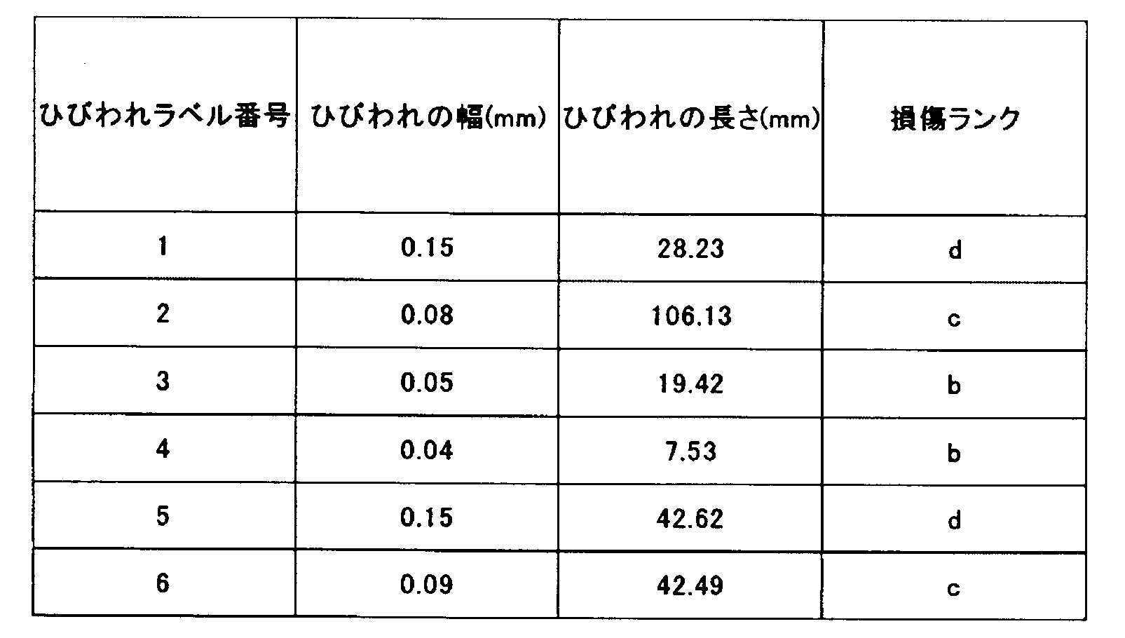
次に、図2に示されるように、外部入出力部102は、ひび割れ評価装置10に記憶されている評価結果のデータを出力する出力部として機能する。評価結果のデータは、CPU110において、ユーザの要求する出力形式(例えば、CSV(comma-separated values)形式)に変換される。出力形式は、特に限定されない。評価結果をひび割れ評価装置10の外部に出力でき、出力された評価結果を二次利用できる。例えば、表1に示されるような、評価結果のデータが出力される。データの項目等は特に限定されない。
Next, as shown in FIG. 2, the external input / output unit 102 functions as an output unit that outputs the evaluation result data stored in the crack evaluation device 10. The evaluation result data is converted into an output format (for example, CSV (comma-separated values) format) requested by the user in the CPU 110. The output format is not particularly limited. The evaluation result can be output to the outside of the crack evaluation device 10, and the output evaluation result can be secondarily used. For example, the evaluation result data as shown in Table 1 is output. Data items and the like are not particularly limited.
CPU110は、制御部126を備え、ひび割れ評価装置10の全体の動作を制御する。
The CPU 110 includes a control unit 126 and controls the overall operation of the crack evaluation device 10.
ひび割れ評価装置10は、上記の構成に限定されず、要求される処理を実行するためのデバイス、プログラム、及び記憶装置(なお、これらの名称に限定されない)を備えることができる。
The crack evaluation device 10 is not limited to the above configuration, and may include a device, a program, and a storage device (not limited to these names) for executing the required processing.
<ひび割れ評価方法>
次に、上述した構成のひび割れ評価装置10を用いたいひび割れの評価方法について図を参照して説明する。図6は、ひび割れの評価方法のフローチャートである。 <Crack evaluation method>
Next, a crack evaluation method using thecrack evaluation device 10 having the above-described configuration will be described with reference to the drawings. FIG. 6 is a flowchart of a crack evaluation method.
次に、上述した構成のひび割れ評価装置10を用いたいひび割れの評価方法について図を参照して説明する。図6は、ひび割れの評価方法のフローチャートである。 <Crack evaluation method>
Next, a crack evaluation method using the
まず、外部入出力部102により、点検対象構造物の撮像画像を入力する(ステップS100)。外部入出力部102は、撮像装置20との無線通信又は有線通信により、撮像装置20から直接的に撮像画像を入力することができる。データベース30に撮像画像が記憶されている場合、外部入出力部102はデータベース30から撮像画像を入力することができる。記録媒体に撮像画像が記憶されている場合、外部入出力部102は記録媒体から撮像画像を入力することができる。
First, the captured image of the structure to be inspected is input by the external input / output unit 102 (step S100). The external input / output unit 102 can directly input the captured image from the imaging device 20 by wireless communication or wired communication with the imaging device 20. When the captured image is stored in the database 30, the external input / output unit 102 can input the captured image from the database 30. When the captured image is stored in the recording medium, the external input / output unit 102 can input the captured image from the recording medium.
入力される撮像画像は、撮像装置20により撮像日時の情報を含んでいる。撮像日時は必ずしも同じ点検時期の全ての撮像画像において同一である必要はなく、複数日に亘っていてもよい。複数の撮像画像を一括して入力してもよいし、一度に1つの撮像画像を入力するようにしてもよい。なお、本発明において点検対象構造物の「画像」は、撮像装置20により生成された状態の撮像画像でもよいし、撮像装置20により生成された撮像画像に対して何らかの画像処理が施された後の画像でもよい。
The input captured image includes information on the imaging date and time by the imaging device 20. The imaging date and time do not necessarily have to be the same for all captured images at the same inspection period, and may extend over a plurality of days. A plurality of captured images may be input at once, or one captured image may be input at a time. In the present invention, the "image" of the structure to be inspected may be an captured image in a state generated by the imaging device 20, or after some image processing is performed on the captured image generated by the imaging device 20. The image may be.
次に、ひび割れ情報取得部120により、点検対象構造物を撮像した画像を画像処理することにより、構造物のひび割れについて、ひび割れ情報を取得する(ステップS110)。ひび割れ情報取得部120は、例えば、撮像画像からひび割れ抽出することにより、ひび割れ情報を取得する。
Next, the crack information acquisition unit 120 acquires crack information about the cracks in the structure by performing image processing on the image of the structure to be inspected (step S110). The crack information acquisition unit 120 acquires crack information, for example, by extracting cracks from an captured image.
ひび割れは、種々の方法により抽出を行うことができる。例えば特許4006007号公報に記載されたひび割れ検出方法を用いることができる。この方法は、ひび割れとコンクリートを含む疑似画像内のひび割れとコンクリートの濃度をそれぞれ変更して画像をウェーブレット変換することでウェーブレット係数テーブルを予め作成する。そして、ひび割れ検出対象であるコンクリート表面を撮像した入力画像をウェーブレット変換して得られたウェーブレット係数を、予め作成したウェーブレット係数テーブルと比較することことによりひび割れ領域とひび割れでない領域を判定する。
Cracks can be extracted by various methods. For example, the crack detection method described in Japanese Patent No. 4006007 can be used. In this method, a wavelet coefficient table is created in advance by changing the densities of cracks and concrete in a pseudo image including cracks and concrete and wavelet transforming the image. Then, the cracked region and the non-cracked region are determined by comparing the wavelet coefficient obtained by wavelet transforming the input image of the concrete surface to be detected for cracks with the wavelet coefficient table created in advance.
なお、ひび割れ情報取得部120によるひび割れ情報の取得は、撮像画像から損傷の部分画像(以下「損傷部分画像」ともいう)を抽出する場合に限定されない。ひび割れ情報取得部120による損傷の抽出には、撮像画像内の損傷の領域を識別するだけの場合が含まれ、この場合にはひび割れ情報取得部120により撮像画像内の損傷の領域のうち少なくとも一部を示す情報(以下「損傷領域情報」ともいう)が抽出される。
Note that the acquisition of crack information by the crack information acquisition unit 120 is not limited to the case of extracting a damaged partial image (hereinafter, also referred to as “damaged partial image”) from the captured image. The extraction of damage by the crack information acquisition unit 120 includes the case of only identifying the damaged area in the captured image, in which case at least one of the damaged areas in the captured image by the crack information acquisition unit 120. Information indicating the part (hereinafter, also referred to as “damaged area information”) is extracted.
ひび割れ情報取得部120は、例えば、撮像画像と撮像画像から抽出された損傷(損傷部分画像及び損傷領域情報のうち少なくとも一方である)とに基づいて、ひび割れ情報を生成する。ひび割れ情報取得部120は、ひび割れ情報として、ひび割れ領域とひび割れ幅とを含むデータを取得する。撮像画像からひびわれ領域とひび割れ幅を計算できる。長さや角度はひび割れベクトルから計算できる。なお、画像情報に基づいて、長さや向き(角度)のデータを取得することもできる。図6のステップS110で取得されたひび割れ情報は、ひび割れベクトル生成部122に入力される。ひび割れベクトル生成部122は、ひび割れベクトル及び連結ひび割れベクトルを生成する(ステップS120)。
The crack information acquisition unit 120 generates crack information based on, for example, the captured image and the damage extracted from the captured image (at least one of the damaged part image and the damaged area information). The crack information acquisition unit 120 acquires data including a crack region and a crack width as crack information. The cracked area and crack width can be calculated from the captured image. The length and angle can be calculated from the crack vector. It is also possible to acquire length and orientation (angle) data based on the image information. The crack information acquired in step S110 of FIG. 6 is input to the crack vector generation unit 122. The crack vector generation unit 122 generates a crack vector and a connected crack vector (step S120).
ひび割れベクトル生成部122の第1生成部122Aは、ひび割れ情報に基づいて、ひび割れ部分をベクトル化して、ひび割れベクトルを生成する。
The first generation unit 122A of the crack vector generation unit 122 vectorizes the crack portion based on the crack information and generates a crack vector.
第1生成部122Aは、ベクトル化に際して、検出されたひび割れを必要に応じ2値化及び/または細線化する。「ベクトル化」とは、ひび割れに対し始点及び終点で定まる線分を求めることであり、ひび割れが曲線状の場合、曲線と線分の距離が閾値以下になるようにひび割れを複数の区間に分割し、複数の区間のそれぞれについてひび割れベクトルを生成する。
The first generation unit 122A binarizes and / or thins the detected cracks as necessary during vectorization. "Vectoring" is to find a line segment that is determined by the start point and end point for a crack. If the crack is curved, the crack is divided into multiple sections so that the distance between the curve and the line segment is less than the threshold. Then, a crack vector is generated for each of the plurality of intervals.
ひび割れベクトルの生成に際しては、例えば床版2の特徴点を座標系の原点とし、ひび割れベクトルのグループ(ベクトルグループ)について、原点からの距離が最小になる端点を第1の始点とし、以下ひび割れベクトルの走行方向に沿って順次終点、始点を決定することができる。
When generating the crack vector, for example, the feature point of the floor slab 2 is set as the origin of the coordinate system, and for the group of crack vectors (vector group), the end point at which the distance from the origin is minimized is set as the first starting point, and the following crack vector It is possible to determine the end point and the start point in sequence along the traveling direction of.
図7に示されるように、床版2上の点P0を座標系の原点、図の右方向及び下方向をそれぞれ座標系のX軸方向、Y軸方向に設定される。ベクトルグループC7の点P13,P14,P15,P16のうち点P0からの距離dが最も短くなる点P13がひび割れベクトルC7-1の始点と決定される。次に、点P14は、ひび割れベクトルC7-1の終点かつひび割れベクトルC7-2,C7-3の始点と決定され、点P15,P16は、それぞれひび割れベクトルC7-2,C7-3の終点と決定される。同様にベクトルグループC8では、点P17がひび割れベクトルC8-1の始点、点P18がひび割れベクトルC8-2,C8-3の始点とそれぞれ決定される。ここで、図7に示されるようにひび割れベクトルC8-3の走行方向(点P18から点P20へ向かう方向)はひび割れベクトルC8-1の走行方向と逆行する。このような場合は、図8に示されるように、点P19をひび割れベクトルC8A-1の始点とする。そして、点P18をひび割れベクトルC8A-1の終点かつひび割れベクトルC8A-2,C8A-3の始点と決定し、点P17,P20をそれぞれひび割れベクトルC8A-2,C8A-3の終点とするようにしてもよい。なおこの場合のひび割れベクトルの集合体がベクトルグループC8Aと表記される。
As shown in FIG. 7, the point P0 on the plate 2 is set to the origin of the coordinate system, and the right and downward directions of the figure are set to the X-axis direction and the Y-axis direction of the coordinate system, respectively. Of the points P13, P14, P15, and P16 of the vector group C7, the point P13 having the shortest distance d from the point P0 is determined to be the starting point of the crack vector C7-1. Next, the point P14 is determined to be the end point of the crack vector C7-1 and the start point of the crack vectors C7-2 and C7-3, and the points P15 and P16 are determined to be the end points of the crack vectors C7-2 and C7-3, respectively. Will be done. Similarly, in the vector group C8, the point P17 is determined as the start point of the crack vector C8-1, and the point P18 is determined as the start point of the crack vectors C8-2 and C8-3, respectively. Here, as shown in FIG. 7, the traveling direction of the crack vector C8-3 (the direction from the point P18 to the point P20) is opposite to the traveling direction of the crack vector C8-1. In such a case, as shown in FIG. 8, the point P19 is set as the starting point of the crack vector C8A-1. Then, the point P18 is determined as the end point of the crack vector C8A-1 and the start point of the crack vectors C8A-2 and C8A-3, and the points P17 and P20 are set as the end points of the crack vectors C8A-2 and C8A-3, respectively. May be good. The aggregate of crack vectors in this case is referred to as vector group C8A.
上述のようにしてひび割れベクトルを生成する場合、ひび割れが床版2の内部では連続しているが表面では分離していると、分離したひび割れベクトルとして認識されてしまう可能性がある。ひび割れベクトル生成部122の第2生成部122Bは、連結基準に基づいて、空間的に分離した複数のひび割れベクトルを連結する連結ひび割れベクトルを生成する。この連結処理により、複数のひび割れベクトルが連結ひび割れベクトルにより連結され、1のひび割れベクトルとして認識される。ひび割れベクトルの連結は、作業員が複数のひび割れをトレースする処理に相当する。連結基準は、ひび割れベクトル生成部122、又は記憶部108に記憶される。
When the crack vector is generated as described above, if the cracks are continuous inside the floor slab 2 but separated on the surface, they may be recognized as separated crack vectors. The second generation unit 122B of the crack vector generation unit 122 generates a concatenated crack vector that concatenates a plurality of spatially separated crack vectors based on the concatenation standard. By this concatenation process, a plurality of crack vectors are concatenated by the concatenated crack vector and recognized as one crack vector. The connection of crack vectors corresponds to a process in which a worker traces a plurality of cracks. The connection reference is stored in the crack vector generation unit 122 or the storage unit 108.
図9は、1方向のひび割れベクトルの連結の例を示す図である。図9に示されるように、ひび割れベクトルC3-1(点P21、点P22がそれぞれ始点、終点)を含むベクトルグループC3と、ひび割れベクトルC4-1(点P23、点P24がそれぞれ始点、終点)を含むベクトルグループC4とが抽出された状況を示す。また、ひび割れベクトルC3-1が点P22及び点P23を結ぶ線分となす角をα1とし、点P22及び点P23を結ぶ線分がひび割れベクトルC4-1となす角をα2とし、点P22と点P23との距離をLとする。このとき、角α1、角α2、及び距離Lが閾値以下ならば、ひび割れベクトルC3-1及びC4-1を連結し、またベクトルグループC3及びC4を融合させる。図9においては、角α1、角α2及び距離Lと、それぞれの閾値とが、連結基準になる。なお、連結基準は、角α1、角α2及び距離Lに限定されない。
FIG. 9 is a diagram showing an example of connecting crack vectors in one direction. As shown in FIG. 9, a vector group C3 including a crack vector C3-1 (points P21 and P22 are start points and end points, respectively) and a crack vector C4-1 (points P23 and P24 are start points and end points, respectively). The situation in which the including vector group C4 is extracted is shown. Further, the angle formed by the crack vector C3-1 with the line segment connecting the points P22 and P23 is α1, the angle formed by the line segment connecting the points P22 and P23 with the crack vector C4-1 is α2, and the point P22 and the point Let L be the distance from P23. At this time, if the angle α1, the angle α2, and the distance L are equal to or less than the threshold value, the crack vectors C3-1 and C4-1 are connected, and the vector groups C3 and C4 are fused. In FIG. 9, the angle α1, the angle α2, the distance L, and the respective threshold values serve as the connection reference. The connection reference is not limited to the angle α1, the angle α2, and the distance L.
具体的には、図10に示されるように、連結ひび割れベクトルC5-2が生成される。連結ひび割れベクトルC5-2は、ひび割れベクトルC5-1(ひび割れベクトルC3-1と同一)及びC5-3(ひび割れベクトルC4-1と同一)と連結する。これらひび割れベクトルC5-1、及びC5-3と、連結ひび割れベクトルC5-2と、を含む新たなベクトルグループが、ベクトルグループC5になる。このように、空間的に床版2の表面で分離したベクトルを適宜連結させることにより、ベクトル同士の連結関係を正確に把握することができる。ベクトルグループC5は、ひび割れベクトルC5-1、及びC5-3と、連結ひび割れベクトルC5-2のひび割れ情報を保持する。
Specifically, as shown in FIG. 10, the connected crack vector C5-2 is generated. The connected crack vector C5-2 is connected to the crack vector C5-1 (same as the crack vector C3-1) and C5-3 (same as the crack vector C4-1). A new vector group including these crack vectors C5-1 and C5-3 and the concatenated crack vector C5-2 becomes the vector group C5. In this way, by appropriately connecting the vectors spatially separated on the surface of the floor slab 2, the connection relationship between the vectors can be accurately grasped. The vector group C5 holds the crack information of the crack vectors C5-1 and C5-3 and the connected crack vector C5-2.
次に、図11は2方向のひび割れベクトルの連結の例を示す図である。図11では、一部の点、及びひび割れベクトルのみが表示される。図11に示されるように、ベクトルグループC1は、ひび割れベクトルC1-1~C1-3・・・により構成される。これらのひび割れベクトルは点P1~P4・・・を始点または終点とする。
Next, FIG. 11 is a diagram showing an example of connecting crack vectors in two directions. In FIG. 11, only some points and crack vectors are displayed. As shown in FIG. 11, the vector group C1 is composed of crack vectors C1-1 to C1-3 .... These crack vectors have points P1 to P4 ... As a start point or an end point.
ベクトルグループC3は、ひび割れベクトルC3-1~C3-3・・・により構成される。これらのひび割れベクトルは点P31~P34・・・を始点または終点とする。ひび割れベクトルC3-1とC1-2がなす角をαとし、点P31とC1-2との距離をLとする。このとき、角α、及び距離Lが閾値以下ならば、ひび割れベクトルC3-1及びC1-2を連結する。図11においては、角α、距離Lと、それぞれの閾値とが、連結基準になる。なお、連結基準は、角α、及び距離Lに限定されない。
The vector group C3 is composed of crack vectors C3-1 to C3-3 .... These crack vectors have points P31 to P34 ... As a start point or an end point. Let α be the angle formed by the crack vectors C3-1 and C1-2, and let L be the distance between the points P31 and C1-2. At this time, if the angle α and the distance L are equal to or less than the threshold value, the crack vectors C3-1 and C1-2 are connected. In FIG. 11, the angle α, the distance L, and the respective threshold values serve as the connection reference. The connection reference is not limited to the angle α and the distance L.
具体的には、図12に示されるように、連結ひび割れベクトルC3-Nが生成される。連結ひび割れベクトルC3-Nは、ひび割れベクトルC3-1と連結される。ベクトルグループC3は、ひび割れベクトルC3-1~C3-3・・・、及び連結ひび割れベクトルC3-Nと、を含む新たなベクトルグループになる。ベクトルグループC3は、ひび割れベクトルC3-1~C3-3・・・、及び連結ひび割れベクトルC3-Nのひび割れ情報を保持する。
Specifically, as shown in FIG. 12, the connected crack vector C3-N is generated. The connected crack vector C3-N is connected to the crack vector C3-1. The vector group C3 becomes a new vector group including the crack vectors C3-1 to C3-3 ... And the concatenated crack vector C3-N. The vector group C3 holds the crack information of the crack vectors C3-1 to C3-3 ... And the connected crack vector C3-N.
このように、空間的に床版2の表面で分離したベクトルを適宜連結させることにより、ベクトル同士の連結関係を正確に把握することができる。
In this way, by appropriately connecting the vectors spatially separated on the surface of the floor slab 2, the connection relationship between the vectors can be accurately grasped.
図13は、1方向のひび割れベクトルの連結の例を示す図である。図13に示されるように、ひび割れベクトルC1-1からC1-5を含むベクトルグループC1と、ひび割れベクトルC2-1からC2-4を含むベクトルグループC2と、ひび割れベクトルC3-1からC3-5を含むベクトルグループC3と、ひび割れベクトルC4-1とC4-2を含むベクトルグループC4とが、抽出された状況を示す。
FIG. 13 is a diagram showing an example of connecting crack vectors in one direction. As shown in FIG. 13, the vector group C1 containing the crack vectors C1-1 to C1-5, the vector group C2 containing the crack vectors C2-1 to C2-4, and the crack vectors C3-1 to C3-5. The vector group C3 including the crack vector C4-1 and the vector group C4 including the crack vectors C4-1 and C4-2 show the extracted situation.
次に、図14に示されるように、各ベクトルグループC1からC4に含まれる、ひび割れベクトルが膨張処理される。膨張処理は、各ひび割れベクトルから2値化された画像データを作成し、次いで画像データの周囲を意図的に画像データと同じ2値であるデータに置き換える。これにより、各ひび割れベクトルが太くなる。ここでは、膨張処理された各ひび割れベクトルが、ベクトルグループC1からC4を構成する。空間的に分離していたひび割れベクトルが、膨張処理されることにより連結する。図14では、ベクトルグループC1とベクトルグループC2とが連結する。
Next, as shown in FIG. 14, the crack vectors included in each of the vector groups C1 to C4 are expanded. The expansion process creates binarized image data from each crack vector, and then intentionally replaces the periphery of the image data with data having the same binary value as the image data. As a result, each crack vector becomes thicker. Here, each expansion-processed crack vector constitutes vector groups C1 to C4. The spatially separated crack vectors are connected by expansion processing. In FIG. 14, the vector group C1 and the vector group C2 are connected.
図15に示されるように、膨張処理された各ひび割れベクトル同士が、接触している領域(又は線群ともいう)は、一つのベクトルグループを構成する。図15では、当初のベクトルグループC1とC3とが連結したベクトルグループC1、当初から存在するベクトルグループC3及びC4により3つベクトルグループが構成される。
As shown in FIG. 15, the region (also referred to as a line group) in which the expanded crack vectors are in contact with each other constitutes one vector group. In FIG. 15, three vector groups are formed by the vector group C1 in which the initial vector groups C1 and C3 are connected, and the vector groups C3 and C4 existing from the beginning.
図16に示されるように、膨張されたひび割れベクトルが元の状態に戻される。図15で複数のひび割れベクトルが、1つのベクトルグループを構成すると判断されると、次の処理が行われる。1つのベクトルグループの含まれる空間的に分離する複数のひび割れベクトルは、連結ひび割れベクトルにより連結される。
As shown in FIG. 16, the expanded crack vector is returned to its original state. When it is determined in FIG. 15 that a plurality of crack vectors constitute one vector group, the following processing is performed. A plurality of spatially separated crack vectors containing one vector group are connected by a concatenated crack vector.
具体的には、図16に示されるように、当初のベクトルグループC1とC3とを連結する連結ひび割れベクトルC1-6が形成される。ひび割れベクトルC1-1からC1-5、ひび割れベクトルC1-7からC1-10及び連結ひび割れベクトルC1-6と、を含む新たなベクトルグループが、ベクトルグループC1を構成する。このように、空間的に(床版2の表面で)分離したベクトルを適宜連結させることにより、ベクトル同士の連結関係を正確に把握することができる。ベクトルグループC1は、ひび割れベクトルC1-1からC1-5、ひび割れベクトルC1-7からC1-10及び連結ひび割れベクトルC1-6のひび割れ情報を保持する。膨張処理では、ひび割れベクトルを膨張させる程度が閾値として設定され、その閾値が連結基準となる。
Specifically, as shown in FIG. 16, a connected crack vector C1-6 that connects the initial vector groups C1 and C3 is formed. A new vector group including the crack vectors C1-1 to C1-5, the crack vectors C1-7 to C1-10, and the connected crack vector C1-6 constitutes the vector group C1. By appropriately connecting the spatially separated vectors (on the surface of the floor slab 2) in this way, the connection relationship between the vectors can be accurately grasped. The vector group C1 holds the crack information of the crack vectors C1-1 to C1-5, the crack vectors C1-7 to C1-10, and the connected crack vector C1-6. In the expansion process, the degree to which the crack vector is expanded is set as a threshold value, and the threshold value serves as a connection reference.
第1生成部122A、及び第2生成部122Bの処理が終了すると、階層構造情報生成部122Cは、ひび割れベクトルの階層構造を示す階層構造情報を生成する。階層構造情報は、ひび割れベクトル同士の連結関係を階層的に表現した情報である。階層構造情報は、複数のひび割れベクトルによって構成されるベクトルグループのうちで各ベクトルがどの階層に属するかを示す階層識別情報(「所属階層情報」ともいう)を含む。階層識別情報は、例えば、数字で表現された階層番号を用いることができる。数字以外のコード(例えば英字、記号を含む)で表現してもよい。
When the processing of the first generation unit 122A and the second generation unit 122B is completed, the hierarchical structure information generation unit 122C generates hierarchical structure information indicating the hierarchical structure of the crack vector. Hierarchical structure information is information that hierarchically expresses the connection relationship between crack vectors. The hierarchical structure information includes hierarchical identification information (also referred to as “affiliation hierarchical information”) indicating which hierarchy each vector belongs to in a vector group composed of a plurality of crack vectors. As the layer identification information, for example, a layer number represented by a number can be used. It may be expressed by a code other than numbers (including, for example, letters and symbols).
ひび割れベクトル生成部122は、損傷情報に対して各種の属性情報(「付加情報」ともいう)を付加できる。例えば、ひび割れの場合、ひび割れが生じている位置及び方向だけでなく、ひび割れの長さ、幅、ひび割れ同士の間隔、及びひび割れの密度をそれぞれ示す各種の属性情報が損傷情報に対して付加できる。
The crack vector generation unit 122 can add various attribute information (also referred to as "additional information") to the damage information. For example, in the case of cracks, various attribute information indicating not only the position and direction in which the cracks occur, but also the length and width of the cracks, the distance between the cracks, and the density of the cracks can be added to the damage information.
<ひび割れベクトル情報>
図17は、ひび割れベクトル情報の例である。ひび割れベクトル情報は、ひび割れベクトルが所属するベクトルグループの情報と、各ひび割れベクトルの固有情報と、ベクトルグループ内において各ひび割れベクトルに連結する他のひび割れベクトルの情報と、付加情報と、から構成される。 <Crack vector information>
FIG. 17 is an example of crack vector information. The crack vector information is composed of information on the vector group to which the crack vector belongs, unique information on each crack vector, information on other crack vectors connected to each crack vector in the vector group, and additional information. ..
ベクトルグループ(図17の表の場合では、ベクトルグループC1;図18参照)の情報はグループのラベル(識別情報)を含む。ひび割れベクトルの固有情報は、ひび割れベクトルのラベル(識別情報)、階層(レベル;所属階層情報)、始点及び終点(点番号及び位置座標)、及び長さを含む。ここで階層(レベル)は、レベル1が最上位であり、数字が大きくなるほど下位の階層になる。具体的な階層の決定方法については詳細を後述する。他のひび割れベクトルの情報は、以下に説明するように親ベクトル、兄弟ベクトル、及び子ベクトルのラベル(識別情報)を含む。付加情報は、損傷の幅、削除操作フラグ、追加操作フラグ、点検日、及び補修情報を含む。
The information of the vector group (in the case of the table of FIG. 17, vector group C1; see FIG. 18) includes the label (identification information) of the group. The unique information of the crack vector includes the label (identification information), the hierarchy (level; belonging hierarchy information), the start point and the end point (point number and position coordinates), and the length of the crack vector. Here, level 1 is the highest level, and the higher the number, the lower the level. Details of the method for determining the specific hierarchy will be described later. Information on other crack vectors includes labels (identification information) for the parent vector, sibling vector, and child vector as described below. Additional information includes damage width, delete operation flag, additional operation flag, inspection date, and repair information.
<親ベクトル、兄弟ベクトル、及び子ベクトル>
本実施形態において、一のひび割れベクトルの終点が他のひび割れベクトルの始点となっている場合、そのような一のひび割れベクトルを「親ベクトル」といい、他のひび割れベクトルを「子ベクトル」という。親ベクトルは1つのひび割れベクトルについてゼロまたは1つとなるように決めるものとするが、子ベクトルは1つの親ベクトルに対しゼロ以上の任意の数だけ存在していてよい。また、親ベクトルの終点が複数の子ベクトルの始点となっている場合、それら複数の子ベクトルは互いに「兄弟ベクトル」という。兄弟ベクトルも、ゼロ以上の任意の数だけ存在していてよい。 <Parent vector, sibling vector, and child vector>
In the present embodiment, when the end point of one crack vector is the start point of another crack vector, such one crack vector is referred to as a "parent vector", and the other crack vector is referred to as a "child vector". The parent vector is determined to be zero or one for one crack vector, but there may be any number of child vectors greater than or equal to zero for one parent vector. When the end point of the parent vector is the start point of a plurality of child vectors, the plurality of child vectors are referred to as "brother vectors" with each other. There may be any number of sibling vectors greater than or equal to zero.
このように、本実施形態では階層構造情報に親ベクトル、兄弟ベクトル、及び子ベクトルのラベル(識別情報)が含まれるので、任意のひび割れベクトルに基づいて、ベクトルのIDを参照して親ベクトル、兄弟ベクトル、及び子ベクトルを順次特定することができる。例えば、あるひび割れベクトルの親ベクトルを特定し、その親ベクトルの親ベクトルをさらに特定することができる。このようにして本実施形態に係るひび割れ評価装置10では、ひび割れベクトル同士の連結関係を容易に把握でき、またひび割れベクトルの分析及び検索を容易に行うことができる。
As described above, in the present embodiment, since the hierarchical structure information includes the labels (identification information) of the parent vector, the sibling vector, and the child vector, the parent vector, referring to the ID of the vector based on an arbitrary crack vector, Sibling vectors and child vectors can be specified in sequence. For example, the parent vector of a crack vector can be specified, and the parent vector of the parent vector can be further specified. In this way, in the crack evaluation device 10 according to the present embodiment, the connection relationship between the crack vectors can be easily grasped, and the crack vector can be easily analyzed and searched.
<付加情報>
付加情報に含まれる「幅」は、各ひび割れベクトルに対応するひび割れの幅を示す。削除操作フラグは削除操作が行われたベクトルであるかどうかを示し、削除操作が行われた場合は“1”、行われていない場合は“0”である。この削除操作フラグを参照して、ひび割れベクトルの表示と非表示とを切り替えることができる。追加操作フラグは、ひび割れベクトルの検出態様に関連しており、自動で検出されたベクトルである場合は“0”、手動で(ユーザの指示入力により)追加されたベクトルである場合は“1”、手動で追加され異なるラベルのベクトルを接続して生成されたベクトルである場合は“2”である。 <Additional information>
The "width" included in the additional information indicates the width of the crack corresponding to each crack vector. The delete operation flag indicates whether or not the vector has been deleted, and is "1" when the delete operation is performed and "0" when the delete operation is not performed. With reference to this delete operation flag, it is possible to switch between showing and hiding the crack vector. The additional operation flag is related to the detection mode of the crack vector, and is "0" when the vector is automatically detected, and "1" when the vector is manually added (by inputting the user's instruction). , "2" if the vector is manually added and generated by connecting vectors with different labels.
「点検日」には損傷の画像を撮像した日を設定するが、操作部106を介したユーザの指示入力により編集することもできる。また「補修」の情報は、操作部106を介したユーザの指示入力(補修の種類及び補修日)に基づいて生成することができる。補修の種類は例えば、セメントで埋める、樹脂で埋める、放置(経過観察)など(図17の表ではそれぞれR1,R2,R3と記載している)がある。
The "inspection date" is set to the date on which the damaged image was captured, but it can also be edited by inputting a user's instruction via the operation unit 106. Further, the "repair" information can be generated based on the user's instruction input (repair type and repair date) via the operation unit 106. The types of repair include, for example, filling with cement, filling with resin, leaving (follow-up), etc. (in the table of FIG. 17, they are described as R1, R2, and R3, respectively).
<ひび割れベクトルの階層>
次に、ひび割れベクトルが所属する階層(レベル)について説明する。ひび割れベクトルの階層は、例えば以下の例で説明するように、種々の手法で決定することができる。 <Hierarchy of crack vectors>
Next, the hierarchy (level) to which the crack vector belongs will be described. The hierarchy of the crack vector can be determined by various methods, for example, as described in the following example.
<階層決定手法>
図18は、ベクトルグループC1を示す図である。ベクトルグループC1は、ひび割れベクトルC1-1からC1-6により構成されており、これらひび割れベクトルは点P1~P7を始点または終点としている。このような状況において例1では、ひび割れベクトルが分岐する(あるひび割れベクトルの終点が他の複数のひび割れベクトルの始点となっている)ごとに階層が下位になるとしている。具体的にはひび割れベクトルC1-1の階層を最も上位のレベル1として、ひび割れベクトルC1-1の終点である点P2を始点とするひび割れベクトルC1-2及びC1-3の階層は、ひび割れベクトルC1-1よりも下位であるレベル2とする。同様に、ひび割れベクトルC1-3の終点である点P4を始点とするひび割れベクトルC1-5及びC1-6の階層は、ひび割れベクトルC1-3よりも下位であるレベル3とする。一方、ひび割れベクトルC1-2の終点である点P3はひび割れベクトルC1-4の始点であるが、点P3を始点とするひび割れベクトルはひび割れベクトルC1-4だけであり分岐はないので、ひび割れベクトルC1-4の階層はC1-2と同じレベル2とする。このようにして決定した各ひび割れベクトルの階層は、図17の表に示すように階層構造情報に含まれる。 <Hierarchy determination method>
FIG. 18 is a diagram showing a vector group C1. The vector group C1 is composed of crack vectors C1-1 to C1-6, and these crack vectors have points P1 to P7 as start points or end points. In such a situation, in Example 1, it is assumed that the hierarchy is lowered each time the crack vector branches (the end point of one crack vector is the start point of a plurality of other crack vectors). Specifically, the hierarchy of the crack vector C1-1 is set to thehighest level 1, and the layers of the crack vectors C1-2 and C1-3 starting from the point P2 which is the end point of the crack vector C1-1 are the crack vector C1. Level 2 is lower than -1. Similarly, the hierarchy of the crack vectors C1-5 and C1-6 starting from the point P4 which is the end point of the crack vector C1-3 is set to level 3 which is lower than the crack vector C1-3. On the other hand, the point P3 which is the end point of the crack vector C1-2 is the start point of the crack vector C1-4, but the crack vector starting from the point P3 is only the crack vector C1-4 and there is no branch, so the crack vector C1 The hierarchy of -4 is the same level 2 as C1-2. The hierarchy of each crack vector determined in this way is included in the hierarchical structure information as shown in the table of FIG.
図18は、ベクトルグループC1を示す図である。ベクトルグループC1は、ひび割れベクトルC1-1からC1-6により構成されており、これらひび割れベクトルは点P1~P7を始点または終点としている。このような状況において例1では、ひび割れベクトルが分岐する(あるひび割れベクトルの終点が他の複数のひび割れベクトルの始点となっている)ごとに階層が下位になるとしている。具体的にはひび割れベクトルC1-1の階層を最も上位のレベル1として、ひび割れベクトルC1-1の終点である点P2を始点とするひび割れベクトルC1-2及びC1-3の階層は、ひび割れベクトルC1-1よりも下位であるレベル2とする。同様に、ひび割れベクトルC1-3の終点である点P4を始点とするひび割れベクトルC1-5及びC1-6の階層は、ひび割れベクトルC1-3よりも下位であるレベル3とする。一方、ひび割れベクトルC1-2の終点である点P3はひび割れベクトルC1-4の始点であるが、点P3を始点とするひび割れベクトルはひび割れベクトルC1-4だけであり分岐はないので、ひび割れベクトルC1-4の階層はC1-2と同じレベル2とする。このようにして決定した各ひび割れベクトルの階層は、図17の表に示すように階層構造情報に含まれる。 <Hierarchy determination method>
FIG. 18 is a diagram showing a vector group C1. The vector group C1 is composed of crack vectors C1-1 to C1-6, and these crack vectors have points P1 to P7 as start points or end points. In such a situation, in Example 1, it is assumed that the hierarchy is lowered each time the crack vector branches (the end point of one crack vector is the start point of a plurality of other crack vectors). Specifically, the hierarchy of the crack vector C1-1 is set to the
次に、表示部104は、生成されたひび割れベクトルと連結ひび割れベクトルとを分類して表示する(ステップS130)。
Next, the display unit 104 classifies and displays the generated crack vector and the connected crack vector (step S130).
表示部104は、ひび割れベクトルと連結ひび割れベクトルが生成されると、自動的にひび割れベクトルと連結ひび割れベクトルを表示できる。また、ユーザは、ひび割れベクトルと連結ひび割れベクトルとが生成されたことの通知を受けることができ、その後、ユーザは、表示部104に、ひび割れベクトルと連結ひび割れベクトルとを表示させることができる。図19は、表示部104に、生成されたひび割れベクトルと連結ひび割れベクトルとを分類して表示した状態を説明する図である。
The display unit 104 can automatically display the crack vector and the connected crack vector when the crack vector and the connected crack vector are generated. Further, the user can be notified that the crack vector and the connected crack vector have been generated, and then the user can display the crack vector and the connected crack vector on the display unit 104. FIG. 19 is a diagram illustrating a state in which the generated crack vector and the connected crack vector are classified and displayed on the display unit 104.
図19に示されるように、表示部104は、例えば、表示画面140と、各種ボタンを備える。各種ボタンとして、例えば、削除ボタン142、選択ボタン144、追加ボタン146、承認ボタン148、拡大ボタン150、縮小ボタン152、「次へ」ボタン154、及び「戻る」ボタン156が含まれる。各種ボタンは、操作部106の一部として機能する。
As shown in FIG. 19, the display unit 104 includes, for example, a display screen 140 and various buttons. The various buttons include, for example, a delete button 142, a select button 144, an add button 146, an approval button 148, an enlargement button 150, a reduce button 152, a "next" button 154, and a "back" button 156. The various buttons function as part of the operation unit 106.
表示画面140にはベクトルグループC1、C3及びC4が表示される。ベクトルグループC1、C3及びC4は、図13から図16に示す処理にしたがって、ひび割れベクトル生成部122により作成されている。
Vector groups C1, C3 and C4 are displayed on the display screen 140. The vector groups C1, C3 and C4 are created by the crack vector generation unit 122 according to the processes shown in FIGS. 13 to 16.
ベクトルグループC1は、ひび割れベクトルC1-1からC1-5、ひび割れベクトルC1-7からC1-10及び連結ひび割れベクトルC1-6を含む。また、ベクトルグループC3は、ひび割れベクトルC3-1からC3-5を含む。ベクトルグループC4は、ひび割れベクトルC4-1及びC4-2を含む。
The vector group C1 includes crack vectors C1-1 to C1-5, crack vectors C1-7 to C1-10, and connected crack vectors C1-6. The vector group C3 also includes crack vectors C3-1 to C3-5. Vector group C4 includes crack vectors C4-1 and C4-2.
本実施形態では、ベクトルグループC1において、ひび割れベクトル生成部122が生成した連結ひび割れベクトルC1-6は、ひび割れベクトルC1-1からC1-5、及びひび割れベクトルC1-7からC1-10とは分類して表示される。分類して表示とは、視覚的に区別できるように表示することを意味する。ひび割れベクトルと連結ひび割れベクトルとが、色分け、線種(実線、点線等)、線幅、及び明るさのいずれか、又はその組み合わせを利用して分類して表示される。
In the present embodiment, in the vector group C1, the connected crack vector C1-6 generated by the crack vector generation unit 122 is classified into the crack vectors C1-1 to C1-5 and the crack vectors C1-7 to C1-10. Is displayed. Sorting and displaying means displaying in a visually distinguishable manner. The crack vector and the connected crack vector are classified and displayed by using any one of color coding, line type (solid line, dotted line, etc.), line width, and brightness, or a combination thereof.
図19のベクトルグループC1において、ひび割れベクトルC1-7からC1-10と連結ひび割れベクトルC1-6とは、異なる線幅により、分類して表示される。ユーザは、ひび割れベクトル生成部122により作成された連結ひび割れベクトルを容易に認識できる。
In the vector group C1 of FIG. 19, the crack vectors C1-7 to C1-10 and the connected crack vector C1-6 are classified and displayed according to different line widths. The user can easily recognize the connected crack vector created by the crack vector generation unit 122.
実施形態のひび割れ評価装置10は、連結基準に基づいて連結ひび割れベクトルを作成するので、ひび割れをトレースする作業員を含むユーザの負担が軽減される。
Since the crack evaluation device 10 of the embodiment creates a connected crack vector based on the connection standard, the burden on the user including the worker who traces the crack is reduced.
次に、操作部106は、表示された複数のひび割れベクトルと連結ひび割れベクトルとを編集するため、ユーザの操作を受け付ける(ステップS140)。
Next, the operation unit 106 accepts a user's operation in order to edit the displayed plurality of crack vectors and the connected crack vector (step S140).
実施形態のひび割れ評価装置10は、連結基準に基づいて連結ひび割れベクトルを作成する。一方、ひび割れベクトル生成部122により作成された連結ひび割れベクトルが、作業員が行うひび割れのトレースと一致しない場合がある。その結果、画像処理によるひび割れベクトルに基づく評価結果が、作業員による損傷程度の評価結果と一致しない懸念がある。
The crack evaluation device 10 of the embodiment creates a connected crack vector based on the connection standard. On the other hand, the connected crack vector created by the crack vector generation unit 122 may not match the crack trace performed by the worker. As a result, there is a concern that the evaluation result based on the crack vector by image processing does not match the evaluation result of the degree of damage by the worker.
ひび割れ評価装置10は、ひび割れベクトル生成部122により作成されたひび割れベクトルと連結ひび割れベクトルに対する編集を操作部106により受け付けることができる。
The crack evaluation device 10 can accept edits to the crack vector created by the crack vector generation unit 122 and the connected crack vector by the operation unit 106.
表示部104に、分類されてひび割れベクトルと連結ひび割れベクトルとが表示されるので、編集の際に、ユーザは連結ひび割れベクトルの良否の判断を容易に行うことができる。
Since the crack vector and the connected crack vector are classified and displayed on the display unit 104, the user can easily judge whether the connected crack vector is good or bad at the time of editing.
次に、具体的な編集の操作について説明する。図20は、編集するための操作の一例を示す図である。連結ひび割れベクトルが問題ない場合の操作を示す。最初に、ユーザは分類表示された連結ひび割れベクトルC1-6を確認する。ユーザは連結ひび割れベクトルC1-6の良否を判断する。連結ひび割れベクトルC1-6に問題がない場合、ユーザは承認ボタン148を押す。ユーザは、必要に応じて拡大ボタン150、及び縮小ボタン152を押し、連結ひび割れベクトルC1-6を詳細に確認できる。
Next, the specific editing operation will be explained. FIG. 20 is a diagram showing an example of an operation for editing. The operation when the concatenated crack vector is not a problem is shown. First, the user confirms the classified and displayed concatenated crack vector C1-6. The user determines the quality of the connected crack vector C1-6. If there is no problem with the concatenated crack vector C1-6, the user presses the approval button 148. The user can press the enlargement button 150 and the reduce button 152 as necessary to check the connected crack vector C1-6 in detail.
ユーザは、「次へ」ボタン154を押すことで、表示部104に別のひび割れベクトルと連結ひび割れベクトルを表示でき、連結ひび割れベクトルの良否を判断できる。
By pressing the "Next" button 154, the user can display another crack vector and a connected crack vector on the display unit 104, and can judge whether the connected crack vector is good or bad.
図21は、編集するための操作の別の例を示す図である。連結ひび割れベクトルを削除する場合の操作を示す。ユーザは分類表示された連結ひび割れベクトルC1-6を確認する。ユーザは連結ひび割れベクトルC1-6の削除を決定する。ユーザは選択ボタン144を押し、削除する連結ひび割れベクトルC1-6を選択する。ユーザは最後の削除ボタン142を押し、連結ひび割れベクトルC1-6を削除する。次いで、ユーザが承認ボタン148を押すことで、連結ひび割れベクトルC1-6の削除が実行される。
FIG. 21 is a diagram showing another example of the operation for editing. The operation when deleting the concatenated crack vector is shown. The user confirms the concatenated crack vector C1-6 classified and displayed. The user decides to delete the concatenated crack vector C1-6. The user presses the select button 144 and selects the concatenated crack vector C1-6 to be deleted. The user presses the last delete button 142 to delete the concatenated crack vector C1-6. Then, when the user presses the approval button 148, the connection crack vector C1-6 is deleted.
連結ひび割れベクトルC1-6が削除されるとベクトルグループC1が2つのベクトルグループになる。ひび割れベクトルの階層構造情報が書き換えられる。例えば、ベクトルグループC1が、ひび割れベクトルC1-1からC1-5を含むベクトルグループC1と、ひび割れベクトルC2-1からC2-4を含むベクトルグループC2に書き換えられる。
When the concatenated crack vector C1-6 is deleted, the vector group C1 becomes two vector groups. The hierarchical structure information of the crack vector is rewritten. For example, the vector group C1 is rewritten into a vector group C1 containing the crack vectors C1-1 to C1-5 and a vector group C2 containing the crack vectors C2-1 to C2-4.
図22は、編集するための操作のさらに別の例を示す図である。連結ひび割れベクトルを追加する場合の操作を示す。ユーザは分類表示された連結ひび割れベクトルC1-6を確認し、さらにベクトルグループC3とベクトルグループC4との連結状況を確認し、ベクトルグループC3とベクトルグループC4とを連結する連結ひび割れベクトルを追加することを決定する。
FIG. 22 is a diagram showing still another example of the operation for editing. The operation when adding a concatenated crack vector is shown. The user confirms the concatenated crack vector C1-6 classified and displayed, further confirms the concatenation status of the vector group C3 and the vector group C4, and adds a concatenated crack vector connecting the vector group C3 and the vector group C4. To determine.
ユーザは選択ボタン144を押し、連結対象となるひび割れベクトルC3-5とひび割れベクトルC4-1とを選択し、次いで、追加ボタン146を押す。新規の連結ひび割れベクトルC34が表示され、ひび割れベクトルC3-5とひび割れベクトルC4-1とを連結する。新規の連結ひび割れベクトルC34は、ひび割れベクトルC1-1からC1-5、C1-7からC1-10、C3-1からC3-5、C4-1とC4-1、及び連結ひび割れベクトルC1-6とは分類して表示される。実施形態では、新規の連結ひび割れベクトルC34は点線で表示される。ユーザは、ひび割れベクトル生成部122により生成された連結ひび割れベクトルと、ユーザにより追加された新規の連結ひび割れベクトルとを認識できる。
The user presses the selection button 144, selects the crack vector C3-5 and the crack vector C4-1 to be connected, and then presses the add button 146. A new connection crack vector C34 is displayed, and the crack vector C3-5 and the crack vector C4-1 are connected. The new concatenated crack vector C34 includes the crack vectors C1-1 to C1-5, C1-7 to C1-10, C3-1 to C3-5, C4-1 and C4-1, and the concatenated crack vector C1-6. Are categorized and displayed. In the embodiment, the new connecting crack vector C34 is indicated by a dotted line. The user can recognize the connected crack vector generated by the crack vector generation unit 122 and the new connected crack vector added by the user.
次いで、ユーザが承認ボタン148を押すことで、新規の連結ひび割れベクトルC34の追加が実行される。
Next, when the user presses the approval button 148, the addition of a new concatenated crack vector C34 is executed.
新規の連結ひび割れベクトルC34が追加されると、ベクトルグループC3とベクトルグループC4とが1つのベクトルグループを構成する。ひび割れベクトルの階層構造情報が書き換えられる。例えば、新規のベクトルグループC3+4が生成され、ひび割れベクトルC3-1からC3-5、C4-1とC4-1、及び新規の連結ひび割れベクトルC34を含む新規のベクトルグループC3+4に書き換えられる。
When a new connected crack vector C34 is added, the vector group C3 and the vector group C4 form one vector group. The hierarchical structure information of the crack vector is rewritten. For example, a new vector group C3 + 4 is generated and rewritten into a new vector group C3 + 4 including crack vectors C3-1 to C3-5, C4-1 and C4-1, and a new concatenated crack vector C34.
次に、評価部124は編集されたひび割れベクトル及び連結ひび割れベクトルのひび割れ情報に基づいて構造物のひび割れの評価結果を取得する(ステップS150)。
Next, the evaluation unit 124 acquires the evaluation result of the crack of the structure based on the crack information of the edited crack vector and the connected crack vector (step S150).
図23に示されるように、ユーザは、評価結果を、表示部104に表示され、評価結果を確認することができる。例えば、ユーザは、操作部106から指示を入力することで、表示部104に評価結果を表示させる。図23に示されるように、評価結果は、例えば、ひび割れごとに、ひび割れ番号、ひび長さ、及び評価結果(評価区分:ランク情報)が表示される。評価結果毎に色分けして表示することもできる。
As shown in FIG. 23, the user can display the evaluation result on the display unit 104 and confirm the evaluation result. For example, the user inputs an instruction from the operation unit 106 to display the evaluation result on the display unit 104. As shown in FIG. 23, as the evaluation result, for example, the crack number, the crack length, and the evaluation result (evaluation category: rank information) are displayed for each crack. It is also possible to color-code each evaluation result and display it.
ユーザは、要素番号を選択し、承認ボタン148を押すと、評価結果の詳細を確認できる。階層構造情報が表示される。また、ユーザは、評価結果の根拠情報、例えば図4又は図5に示されるひび割れの損傷程度の評価基準を表示部104に表示させることができる。ユーザは評価結果の妥当性を判断できる。
The user can confirm the details of the evaluation result by selecting the element number and pressing the approval button 148. Hierarchical structure information is displayed. In addition, the user can display the basis information of the evaluation result, for example, the evaluation standard of the degree of crack damage shown in FIG. 4 or FIG. 5 on the display unit 104. The user can judge the validity of the evaluation result.
ユーザは、評価結果の詳細を確認し、評価結果を編集できる。ユーザは、編集したい評価結果を選択する。表示部104は、例えば、評価結果の編集画面に切り替わる。ユーザは評価区分の欄に、評価区分をキーボード等で直接入力することができる。また、ユーザは評価区分の欄に表示されるドロップダウンリストの中から評価区分を選択できる。このようにして、ユーザは評価区分を編集できる。次いで、ユーザが承認ボタン148を押すことにより、評価区分の編集が実行される。
The user can check the details of the evaluation result and edit the evaluation result. The user selects the evaluation result to be edited. The display unit 104 switches to, for example, an evaluation result editing screen. The user can directly input the evaluation category in the evaluation category field with a keyboard or the like. In addition, the user can select an evaluation category from the drop-down list displayed in the evaluation category column. In this way, the user can edit the evaluation category. Then, when the user presses the approval button 148, the evaluation category is edited.
また、ユーザは、連結基準を編集できる。図24は、連結基準を編集するための操作の一例を示す図である。図24に示されるように、ユーザは、連結基準編集画面を表示部104に表示できる。図24においては、表示部104は連結基準編集の一例として、「(1)1方向ひび割れ」と「(2)2方向ひび割れ」とを表示する。1方向ひび割れの連結基準となる角α1(°)、角α2(°)、及び距離L(mm)が表示されている。また、2方向ひび割れの連結基準となる角α(°)及び距離L(mm)が表示される。ユーザは編集したい連結基準を選択する。ユーザは連結基準の欄に、キーボード等で閾値を直接入力することができる。また、ユーザは連結基準の欄に表示されるドロップダウンリストの中から閾値を選択できる。次いで、ユーザが承認ボタン148を押すことにより、評価区分の編集が実行される。
Also, the user can edit the consolidation criteria. FIG. 24 is a diagram showing an example of an operation for editing the connection reference. As shown in FIG. 24, the user can display the connection reference editing screen on the display unit 104. In FIG. 24, the display unit 104 displays "(1) one-way crack" and "(2) two-way crack" as an example of the connection reference editing. The angle α1 (°), the angle α2 (°), and the distance L (mm), which are the reference for connecting the one-way cracks, are displayed. Further, the angle α (°) and the distance L (mm), which are the reference for connecting the two-way cracks, are displayed. The user selects the concatenation criteria he wants to edit. The user can directly input the threshold value in the connection standard field with a keyboard or the like. In addition, the user can select a threshold value from the drop-down list displayed in the concatenation criteria column. Then, when the user presses the approval button 148, the evaluation category is edited.
本発明に係るひび割れ評価装置を実現するハードウエアは、各種のプロセッサ(processor)で構成できる。各種プロセッサには、プログラムを実行して各種の処理部として機能する汎用的なプロセッサであるCPU(Central Processing Unit)、FPGA(Field Programmable Gate Array)などの製造後に回路構成を変更可能なプロセッサであるプログラマブルロジックデバイス(Programmable Logic Device;PLD)、ASIC(Application Specific Integrated Circuit)などの特定の処理を実行させるために専用に設計された回路構成を有するプロセッサである専用電気回路などが含まれる。画像表示装置を構成する1つの処理部は、上記各種プロセッサのうちの1つで構成されていてもよいし、同種又は異種の2つ以上のプロセッサで構成されてもよい。例えば、1つの処理部は、複数のFPGA、あるいは、CPUとFPGAの組み合わせによって構成されてもよい。また、複数の処理部を1つのプロセッサで構成してもよい。複数の処理部を1つのプロセッサで構成する例としては、第1に、クライアントやサーバなどのコンピュータに代表されるように、1つ以上のCPUとソフトウェアの組み合わせで1つのプロセッサを構成し、このプロセッサが複数の処理部として機能する形態がある。第2に、システムオンチップ(System On Chip;SoC)などに代表されるように、複数の処理部を含むシステム全体の機能を1つのIC(Integrated Circuit)チップで実現するプロセッサを使用する形態がある。このように、各種の処理部は、ハードウエア的な構造として、上記各種プロセッサを1つ以上用いて構成される。さらに、これらの各種のプロセッサのハードウエア的な構造は、より具体的には、半導体素子などの回路素子を組み合わせた電気回路(circuitry)である。
The hardware that realizes the crack evaluation device according to the present invention can be configured by various processors. Various processors include CPUs (Central Processing Units) and FPGAs (Field Programmable Gate Arrays), which are general-purpose processors that execute programs and function as various processing units, and whose circuit configurations can be changed after manufacturing. It includes a dedicated electric circuit which is a processor having a circuit configuration specially designed for executing a specific process such as a programmable logic device (PLD) and an ASIC (Application Specific Integrated Circuit). One processing unit constituting the image display device may be composed of one of the above-mentioned various processors, or may be composed of two or more processors of the same type or different types. For example, one processing unit may be composed of a plurality of FPGAs or a combination of a CPU and an FPGA. Further, a plurality of processing units may be configured by one processor. As an example of configuring a plurality of processing units with one processor, first, one processor is configured by a combination of one or more CPUs and software, as represented by a computer such as a client or a server. There is a form in which the processor functions as a plurality of processing units. Secondly, as typified by System On Chip (SoC), there is a form in which a processor that realizes the functions of the entire system including a plurality of processing units with one IC (Integrated Circuit) chip is used. is there. As described above, the various processing units are configured by using one or more of the above-mentioned various processors as a hardware structure. Further, the hardware structure of these various processors is, more specifically, an electric circuit (circuitry) in which circuit elements such as semiconductor elements are combined.
以上、本発明について説明したが、本発明は、以上の例には限定されず、本発明の要旨を逸脱しない範囲において、各種の改良や変形を行ってもよい。
Although the present invention has been described above, the present invention is not limited to the above examples, and various improvements and modifications may be made without departing from the gist of the present invention.
1 橋梁
2 床版
2 レベル
3 主桁
3 レベル
3A 接合部
10 ひび割れ評価装置
20 撮像装置
30 データベース
102 外部入出力部
104 表示部
106 操作部
108 記憶部
120 ひび割れ情報取得部
122 ひび割れベクトル生成部
122A 第1生成部
122B 第2生成部
122C 階層構造情報生成部
124 評価部
126 制御部
140 表示画面
142 削除ボタン
144 選択ボタン
146 追加ボタン
148 承認ボタン
150 拡大ボタン
152 縮小ボタン
154 「次へ」ボタン
156 「戻る」ボタン
d 距離
L 距離
α 角
α1 角
α2 角 1Bridge 2 Floor slab 2 Level 3 Main girder 3 Level 3A Joint part 10 Crack evaluation device 20 Imaging device 30 Database 102 External input / output unit 104 Display unit 106 Operation unit 108 Storage unit 120 Crack information acquisition unit 122 Crack vector generation unit 122A No. 1 Generation unit 122B Second generation unit 122C Hierarchical structure information generation unit 124 Evaluation unit 126 Control unit 140 Display screen 142 Delete button 144 Select button 146 Add button 148 Approval button 150 Enlarge button 152 Reduce button 154 "Next" button 156 "Back" Button d Distance L Distance α Angle α1 Angle α2 Angle
2 床版
2 レベル
3 主桁
3 レベル
3A 接合部
10 ひび割れ評価装置
20 撮像装置
30 データベース
102 外部入出力部
104 表示部
106 操作部
108 記憶部
120 ひび割れ情報取得部
122 ひび割れベクトル生成部
122A 第1生成部
122B 第2生成部
122C 階層構造情報生成部
124 評価部
126 制御部
140 表示画面
142 削除ボタン
144 選択ボタン
146 追加ボタン
148 承認ボタン
150 拡大ボタン
152 縮小ボタン
154 「次へ」ボタン
156 「戻る」ボタン
d 距離
L 距離
α 角
α1 角
α2 角 1
Claims (11)
- 構造物を撮像した画像を画像処理して、構造物のひび割れについてのひび割れ情報を取得するひび割れ情報取得部、
前記取得したひび割れ情報に基づいてひび割れベクトルを生成する第1生成部と、生成された前記ひび割れベクトルの中で、空間的に分離した前記ひび割れベクトルを、連結基準に基づいて連結する連結ひび割れベクトルを生成する第2生成部と、を備えるひび割れベクトル生成部と、
生成された前記ひび割れベクトルと前記連結ひび割れベクトルとを分類して表示する表示部と、
表示された前記ひび割れベクトルと前記連結ひび割れベクトルとを編集するため、ユーザの操作を受け付ける操作部と、
編集された前記ひび割れベクトル及び前記連結ひび割れベクトルのひび割れ情報に基づいて構造物のひび割れの評価結果を取得する評価部と、
を備えるひび割れ評価装置。 Crack information acquisition unit, which acquires crack information about cracks in a structure by performing image processing on the image of the captured structure.
A first generation unit that generates a crack vector based on the acquired crack information, and a connected crack vector that connects the spatially separated crack vectors in the generated crack vector based on a connection reference. A crack vector generation unit including a second generation unit to be generated,
A display unit that classifies and displays the generated crack vector and the connected crack vector, and
An operation unit that accepts user operations to edit the displayed crack vector and the connected crack vector.
An evaluation unit that acquires the evaluation result of cracks in a structure based on the edited crack information of the crack vector and the connected crack vector.
A crack evaluation device equipped with. - 前記編集は、前記連結ひび割れベクトルを削除すること、及び空間的に分離した前記ひび割れベクトルを連結する新規の連結ひび割れベクトルを生成することを含む、請求項1に記載のひび割れ評価装置。 The crack evaluation device according to claim 1, wherein the editing includes deleting the connected crack vector and generating a new connected crack vector that connects the spatially separated crack vectors.
- 前記表示部は、前記新規の連結ひび割れベクトルを、前記ひび割れベクトル及び前記連結ひび割れベクトルと分類して表示する請求項2に記載のひび割れ評価装置。 The crack evaluation device according to claim 2, wherein the display unit classifies and displays the new connected crack vector as the crack vector and the connected crack vector.
- 前記表示部は、前記評価結果を表示する、請求項1から3のいずれ一項に記載のひび割れ評価装置。 The crack evaluation device according to any one of claims 1 to 3, wherein the display unit displays the evaluation result.
- 前記評価結果のデータを出力する出力部を備える請求項1から4のいずれ一項に記載のひび割れ評価装置。 The crack evaluation device according to any one of claims 1 to 4, further comprising an output unit that outputs the evaluation result data.
- 前記表示部は、前記評価結果の根拠情報を表示する請求項1から5のいずれ一項に記載のひび割れ評価装置。 The crack evaluation device according to any one of claims 1 to 5, wherein the display unit displays the basis information of the evaluation result.
- 前記操作部は、前記評価結果を編集するため、ユーザの操作を受け付ける請求項1から6のいずれ一項に記載のひび割れ評価装置。 The crack evaluation device according to any one of claims 1 to 6, wherein the operation unit accepts a user's operation in order to edit the evaluation result.
- 前記操作部は、前記連結基準を編集するため、ユーザの操作を受け付ける請求項1から7のいずれ一項に記載のひび割れ評価装置。 The crack evaluation device according to any one of claims 1 to 7, wherein the operation unit accepts a user's operation in order to edit the connection standard.
- 前記ひび割れ情報は、ひび割れ領域とひび割れ幅とを含むデータである請求項1から8のいずれ一項に記載のひび割れ評価装置。 The crack evaluation device according to any one of claims 1 to 8, wherein the crack information is data including a crack region and a crack width.
- コンピュータが、
構造物を撮像した画像を画像処理して、構造物のひび割れについてのひび割れ情報を取得するステップと、
前記取得したひび割れ情報に基づいて複数のひび割れベクトルを生成し、かつ生成された前記複数のひび割れベクトルの中で、空間的に分離した複数のひび割れベクトルを連結する連結ひび割れベクトルを生成するステップと、
生成された前記複数のひび割れベクトルと前記連結ひび割れベクトルとを分類して表示するステップと、
表示された前記複数のひび割れベクトルと前記連結ひび割れベクトルとを編集するため、ユーザの操作を受け付けるステップと、
編集された前記複数のひび割れベクトル及び前記連結ひび割れベクトルのひび割れ情報に基づいて構造物のひび割れの評価結果を取得するステップと、
を実行するひび割れ評価方法。 The computer
A step of image processing an image of a structure to obtain crack information about the crack of the structure, and
A step of generating a plurality of crack vectors based on the acquired crack information, and generating a connected crack vector connecting a plurality of spatially separated crack vectors among the generated crack vectors, and a step of generating a connected crack vector.
A step of classifying and displaying the generated plurality of crack vectors and the connected crack vector, and
In order to edit the displayed plurality of crack vectors and the connected crack vector, a step of accepting a user's operation and
A step of acquiring the evaluation result of the crack of the structure based on the edited crack information of the plurality of crack vectors and the connected crack vector, and
How to evaluate cracks. - 請求項10に記載のひび割れ評価方法をコンピュータに実行させるためのひび割れ評価プログラム。 A crack evaluation program for causing a computer to execute the crack evaluation method according to claim 10.
Priority Applications (3)
| Application Number | Priority Date | Filing Date | Title |
|---|---|---|---|
| JP2021534569A JP7256271B2 (en) | 2019-07-23 | 2020-05-28 | Crack evaluation device, crack evaluation method, and crack evaluation program |
| EP20843377.1A EP4006842A4 (en) | 2019-07-23 | 2020-05-28 | Crack evaluation device, crack evaluation method, and crack evaluation program |
| US17/580,412 US20220148150A1 (en) | 2019-07-23 | 2022-01-20 | Crack evaluation apparatus, crack evaluation method, and crack evaluation program |
Applications Claiming Priority (2)
| Application Number | Priority Date | Filing Date | Title |
|---|---|---|---|
| JP2019135152 | 2019-07-23 | ||
| JP2019-135152 | 2019-07-23 |
Related Child Applications (1)
| Application Number | Title | Priority Date | Filing Date |
|---|---|---|---|
| US17/580,412 Continuation US20220148150A1 (en) | 2019-07-23 | 2022-01-20 | Crack evaluation apparatus, crack evaluation method, and crack evaluation program |
Publications (1)
| Publication Number | Publication Date |
|---|---|
| WO2021014754A1 true WO2021014754A1 (en) | 2021-01-28 |
Family
ID=74194148
Family Applications (1)
| Application Number | Title | Priority Date | Filing Date |
|---|---|---|---|
| PCT/JP2020/021193 WO2021014754A1 (en) | 2019-07-23 | 2020-05-28 | Crack evaluation device, crack evaluation method, and crack evaluation program |
Country Status (4)
| Country | Link |
|---|---|
| US (1) | US20220148150A1 (en) |
| EP (1) | EP4006842A4 (en) |
| JP (1) | JP7256271B2 (en) |
| WO (1) | WO2021014754A1 (en) |
Cited By (1)
| Publication number | Priority date | Publication date | Assignee | Title |
|---|---|---|---|---|
| JP7076932B1 (en) | 2021-03-02 | 2022-05-30 | 中日本高速道路株式会社 | Pavement soundness evaluation method |
Families Citing this family (2)
| Publication number | Priority date | Publication date | Assignee | Title |
|---|---|---|---|---|
| WO2020110560A1 (en) * | 2018-11-29 | 2020-06-04 | 富士フイルム株式会社 | Inspection assistance device, inspection assistance method, and inspection assistance program for concrete structure |
| US12045966B2 (en) * | 2019-10-08 | 2024-07-23 | Shanghai Oriental Maritime Engineering Technology Co., Ltd. | Tunnel-inspection image acquisition device, tunnel-inspection system, and tunnel-inspection method |
Citations (5)
| Publication number | Priority date | Publication date | Assignee | Title |
|---|---|---|---|---|
| JPH06148089A (en) | 1992-05-29 | 1994-05-27 | Shimizu Corp | Craze measuring processor |
| JP2002257744A (en) | 2001-03-02 | 2002-09-11 | Takenaka Komuten Co Ltd | Method and device for inspecting defect of concrete |
| JP2005227829A (en) * | 2004-02-10 | 2005-08-25 | Kajima Corp | Inspection and investigation support system for concrete wall surface |
| JP4006007B2 (en) | 2004-11-10 | 2007-11-14 | 大成建設株式会社 | Crack detection method |
| WO2017126367A1 (en) * | 2016-01-22 | 2017-07-27 | 富士フイルム株式会社 | Crack information editing device, crack information editing method, and crack information editing program |
Family Cites Families (12)
| Publication number | Priority date | Publication date | Assignee | Title |
|---|---|---|---|---|
| JP2006132973A (en) * | 2004-11-02 | 2006-05-25 | Fujimitsu Komuten:Kk | Crack inspection device and method of concrete structure |
| JP6454422B2 (en) * | 2015-09-10 | 2019-01-16 | 富士フイルム株式会社 | Damage information extraction apparatus, damage information extraction method, and damage information extraction program |
| EP3352129B1 (en) * | 2015-09-16 | 2019-10-02 | FUJIFILM Corporation | Soundness determination device, soundness determination method and soundness determination program |
| WO2017051554A1 (en) * | 2015-09-25 | 2017-03-30 | 富士フイルム株式会社 | Maintenance plan devising assistance system, method, and program |
| WO2017056930A1 (en) * | 2015-09-30 | 2017-04-06 | 富士フイルム株式会社 | Image registration device, image registration method, image registration system, and imaging terminal |
| CN108431585B (en) * | 2015-12-25 | 2021-09-14 | 富士胶片株式会社 | Information processing apparatus and information processing method |
| WO2017110280A1 (en) * | 2015-12-25 | 2017-06-29 | 富士フイルム株式会社 | Similar-damage search device and similar-damage search method |
| WO2017119154A1 (en) * | 2016-01-07 | 2017-07-13 | 三菱電機株式会社 | Detection device and detection method |
| CN108463717B (en) * | 2016-01-26 | 2021-05-25 | 富士胶片株式会社 | Crack information detection device, crack information detection method, and storage medium |
| JP6848321B2 (en) * | 2016-10-06 | 2021-03-24 | 富士通株式会社 | Road surface condition detection program and road surface condition detection device |
| JP6807459B2 (en) * | 2017-07-25 | 2021-01-06 | 富士フイルム株式会社 | Damage diagram creation method, damage diagram creation device, damage diagram creation system, and recording medium |
| JP7344692B2 (en) * | 2019-07-22 | 2023-09-14 | キヤノン株式会社 | Information processing device, information processing method, and program |
-
2020
- 2020-05-28 EP EP20843377.1A patent/EP4006842A4/en active Pending
- 2020-05-28 WO PCT/JP2020/021193 patent/WO2021014754A1/en unknown
- 2020-05-28 JP JP2021534569A patent/JP7256271B2/en active Active
-
2022
- 2022-01-20 US US17/580,412 patent/US20220148150A1/en not_active Abandoned
Patent Citations (5)
| Publication number | Priority date | Publication date | Assignee | Title |
|---|---|---|---|---|
| JPH06148089A (en) | 1992-05-29 | 1994-05-27 | Shimizu Corp | Craze measuring processor |
| JP2002257744A (en) | 2001-03-02 | 2002-09-11 | Takenaka Komuten Co Ltd | Method and device for inspecting defect of concrete |
| JP2005227829A (en) * | 2004-02-10 | 2005-08-25 | Kajima Corp | Inspection and investigation support system for concrete wall surface |
| JP4006007B2 (en) | 2004-11-10 | 2007-11-14 | 大成建設株式会社 | Crack detection method |
| WO2017126367A1 (en) * | 2016-01-22 | 2017-07-27 | 富士フイルム株式会社 | Crack information editing device, crack information editing method, and crack information editing program |
Cited By (2)
| Publication number | Priority date | Publication date | Assignee | Title |
|---|---|---|---|---|
| JP7076932B1 (en) | 2021-03-02 | 2022-05-30 | 中日本高速道路株式会社 | Pavement soundness evaluation method |
| JP2022133870A (en) * | 2021-03-02 | 2022-09-14 | 中日本高速道路株式会社 | Pavement soundness evaluation method |
Also Published As
| Publication number | Publication date |
|---|---|
| US20220148150A1 (en) | 2022-05-12 |
| JPWO2021014754A1 (en) | 2021-01-28 |
| EP4006842A4 (en) | 2022-09-07 |
| EP4006842A1 (en) | 2022-06-01 |
| JP7256271B2 (en) | 2023-04-11 |
Similar Documents
| Publication | Publication Date | Title |
|---|---|---|
| WO2021014754A1 (en) | Crack evaluation device, crack evaluation method, and crack evaluation program | |
| JP7102569B2 (en) | Damage information processing device, damage information processing method, and damage information processing program | |
| CN108463717B (en) | Crack information detection device, crack information detection method, and storage medium | |
| JP7241139B2 (en) | Server device, image processing method, and image processing system | |
| JP6576473B2 (en) | Crack information editing apparatus, crack information editing method, and crack information editing program | |
| KR20130139762A (en) | System, method and computer program product for detection of defects within inspection images | |
| JP6874096B2 (en) | Damage diagram editing device and program | |
| JP7170023B2 (en) | DAMAGE DATA EDITING DEVICE, DAMAGE DATA EDITING METHOD, PROGRAM, AND SYSTEM | |
| EP3709264B1 (en) | Information processing apparatus and accumulated images selecting method | |
| WO2020110560A1 (en) | Inspection assistance device, inspection assistance method, and inspection assistance program for concrete structure | |
| JP2004251781A (en) | Defect inspection method by image recognition | |
| Kim et al. | Synthetic data and computer-vision-based automated quality inspection system for reused scaffolding | |
| US20220130030A1 (en) | Information display apparatus, information display method, and information display program | |
| JP2018146230A (en) | Structure evaluation method and structure evaluation system | |
| US11971331B2 (en) | Three-dimensional display device, three-dimensional display method, and program | |
| JP7421188B2 (en) | Programs, recording media, and systems | |
| Baishya | Review of Bridge Structural Inspection Aided By Augmented Reality | |
| CN115690090A (en) | Defect sample image generation method, device, equipment and storage medium | |
| CN113205110A (en) | Panel defect classification model establishing method and panel defect classification method | |
| JP2019109191A (en) | Corresponding position calculation method, and corresponding position calculation device | |
| Han et al. | A Comprehensive Framework for Automated Facade Defect Evaluation Using Deep Learning |
Legal Events
| Date | Code | Title | Description |
|---|---|---|---|
| 121 | Ep: the epo has been informed by wipo that ep was designated in this application |
Ref document number: 20843377 Country of ref document: EP Kind code of ref document: A1 |
|
| ENP | Entry into the national phase |
Ref document number: 2021534569 Country of ref document: JP Kind code of ref document: A |
|
| NENP | Non-entry into the national phase |
Ref country code: DE |
|
| ENP | Entry into the national phase |
Ref document number: 2020843377 Country of ref document: EP Effective date: 20220223 |