WO2021009883A1 - 端末及び通信ノード - Google Patents
端末及び通信ノード Download PDFInfo
- Publication number
- WO2021009883A1 WO2021009883A1 PCT/JP2019/028159 JP2019028159W WO2021009883A1 WO 2021009883 A1 WO2021009883 A1 WO 2021009883A1 JP 2019028159 W JP2019028159 W JP 2019028159W WO 2021009883 A1 WO2021009883 A1 WO 2021009883A1
- Authority
- WO
- WIPO (PCT)
- Prior art keywords
- terminal
- data
- communication node
- layer
- communication
- Prior art date
- Legal status (The legal status is an assumption and is not a legal conclusion. Google has not performed a legal analysis and makes no representation as to the accuracy of the status listed.)
- Ceased
Links
Images





Classifications
-
- H—ELECTRICITY
- H04—ELECTRIC COMMUNICATION TECHNIQUE
- H04W—WIRELESS COMMUNICATION NETWORKS
- H04W24/00—Supervisory, monitoring or testing arrangements
- H04W24/10—Scheduling measurement reports ; Arrangements for measurement reports
-
- H—ELECTRICITY
- H04—ELECTRIC COMMUNICATION TECHNIQUE
- H04W—WIRELESS COMMUNICATION NETWORKS
- H04W28/00—Network traffic management; Network resource management
- H04W28/02—Traffic management, e.g. flow control or congestion control
- H04W28/10—Flow control between communication endpoints
- H04W28/14—Flow control between communication endpoints using intermediate storage
Definitions
- the present invention relates to a terminal and a communication node that perform processing at the layer 2 level of a wireless communication protocol.
- LTE LongTermEvolution
- LTE-Advanced LTE-Advanced
- 5G New Radio
- a layer 2 level buffer (hereinafter referred to as a layer 2 buffer) including a packet data convergence protocol (PDCP) layer and a wireless link control (RLC) layer is provided in the terminal (Non-Patent Document 1). reference).
- PDCP packet data convergence protocol
- RLC wireless link control
- downlink data (DL data) transmitted from the communication node and uplink data (UL) transmitted to the communication node are used in the layer 2 buffer using a wireless bearer set between the terminal and the communication node. Data) and are temporarily stored.
- the communication node estimates the amount of DL data accumulated in the layer 2 buffer of the terminal based on the amount of DL data that has not received the delivery confirmation among the DL data transmitted to the terminal.
- the communication node estimates the amount of UL data accumulated in the layer 2 buffer of the terminal based on the buffer status report (BSR) transmitted from the terminal.
- BSR buffer status report
- the communication node determines that there is a possibility of overflow in the layer 2 buffer of the terminal based on the retention amount of DL data and UL data on the terminal side (hereinafter referred to as the retention data amount), the communication node transmits new data. Stop.
- NR defines dual connectivity (DC) in which terminals communicate using wireless resources provided by multiple communication nodes.
- each communication node can estimate the amount of accumulated data in the wireless bearer set between the terminal and the communication node by the method described above.
- each communication node cannot grasp the amount of accumulated data in the wireless bearer set between the terminal and another communication node.
- the present invention has been made in view of such a situation, and when a terminal communicates using wireless resources provided by a plurality of communication nodes, an overflow occurs in a layer 2 level buffer of the terminal. It is an object of the present invention to provide a terminal and a communication node that can surely prevent the occurrence of.
- the terminal (200) is communicated using a plurality of wireless bearers (1, 2) set between the terminal (200) and a plurality of communication nodes (100a, 100b).
- a transmission unit (210) that transmits information indicating the retention state of all data retained in the uplink data and the buffer (240) that stores the downlink data to each of the plurality of communication nodes (100a, 100b), and a specific transmission unit (210).
- a control unit (250) for transmitting information indicating the retention state to the transmission unit (210) based on a trigger is provided.
- the communication node (100a) is uplink data and downlink data that are communicated using a wireless bearer (1) set between the terminal (200) and the communication node (100a).
- the data indicating the retention state of the data retained in the buffer (240) of the terminal (200) is transmitted to another communication node (100b) by the transmission unit (110), and the retention is based on a specific trigger.
- It includes a control unit (150) that causes the transmission unit (110) to transmit information indicating a state.
- FIG. 1 is an overall schematic configuration diagram of the wireless communication system 10.
- FIG. 2A is a diagram illustrating a wireless bearer set between the communication node 100a and the terminal 200.
- FIG. 2B is a diagram illustrating a wireless bearer set between the communication node 100b and the terminal 200.
- FIG. 3 is a diagram illustrating the layer 2 buffer 240.
- FIG. 4 is a functional block configuration diagram of the communication nodes 100a and 100b.
- FIG. 5 is a functional block configuration diagram of the terminal 200.
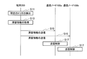
- FIG. 6 is a diagram showing an example of a sequence of procedures for transmitting retention information by the communication nodes 100a and 100b and the terminal 200.
- FIG. 7 is a diagram showing an example of an operation flow of the transmission processing of the retention information by the terminal 200.
- FIG. 1 is an overall schematic configuration diagram of the wireless communication system 10.
- FIG. 2A is a diagram illustrating a wireless bearer set between the communication node 100a and the terminal 200.
- FIG. 2B is
- FIG. 8 is a diagram showing an example of a sequence of procedures for transmitting retention information by the communication nodes 100a and 100b.
- FIG. 9 is a diagram showing an example of an operation flow of the transmission processing of the retention information by the communication node 100a.
- FIG. 10 is a diagram illustrating a modified example of the retention information.
- FIG. 11 is a diagram showing an example of the hardware configuration of the communication nodes 100a and 100b and the terminal 200.
- the wireless communication system 10 includes a Next Generation-Radio Access Network 20 (hereinafter, NG-RAN20) and a terminal 200.
- the terminal is also referred to as a user device (UE).
- NG-RAN20 Next Generation-Radio Access Network 20
- UE user device
- NG-RAN20 includes communication nodes 100a and 100b.
- the specific configuration of the wireless communication system 10 including the number of communication nodes and terminals is not limited to the example shown in FIG.
- NG-RAN20 actually includes multiple NG-RAN Nodes, specifically gNB (or ng-eNB), and is connected to a core network (5GC, not shown) according to NR.
- NG-RAN20 and 5GC may be simply expressed as "network”.
- Each of the communication nodes 100a and 100b is gNB or ng-eNB.
- the communication nodes 100a and 110b execute wireless communication according to NR between the communication nodes 100a and 110b and the terminal 200.
- Massive MIMO which generates a beam with higher directivity by controlling radio signals transmitted from a plurality of antenna elements, and carrier aggregation using a plurality of component carriers (CC). It can support CA) and dual connectivity (DC) that simultaneously transmits CC between multiple NG-RAN Nodes and terminals.
- CC is also called a carrier.
- the wireless communication system 10 may include an Evolved Universal Terrestrial Radio Access Network (E-UTRAN) instead of the NG-RAN20.
- E-UTRAN includes a plurality of E-UTRAN Nodes, specifically eNB (or en-gNB), and is connected to the LTE-compliant core network (EPC).
- EPC LTE-compliant core network
- each of the communication nodes 100a and 110b is an eNB or an en-gNB.
- serving cells are classified as follows.
- the serving cell is a cell in which a wireless link is established between the terminal and the cell.
- the group of serving cells associated with the communication node (master node, MN) that provides the control plane connected to the core network is called the master cell group (MCG).
- MCG is composed of a primary cell (hereinafter, PCell) and one or more secondary cells (hereinafter, SCell).
- PCell is the cell used by the terminal to initiate an initial connection with MN.
- SCell secondary cells
- PCell is the cell used by the terminal to initiate an initial connection with MN.
- the MCG may be composed of only PCell.
- a group of serving cells associated with a communication node (secondary node, SN) that does not provide a control plane connected to the core network and provides additional resources to the terminal is called a secondary cell group (SCG). ..
- the SCG is composed of a primary SCell (hereinafter, PSCell) and one or more SCells.
- PSCell is a cell used by a terminal to initiate an initial connection with an SN.
- the SCG may be composed of only PSCell.
- PCell is also called a special cell (SpCell) in MCG.
- PSCell is also called SpCell in SCG.
- the communication node 100a is MN and the communication node 100b is SN.
- the communication node 100b may be MN and the communication node 100a may be SN.
- the NR defines dual connectivity (DC) in which the terminal 200 communicates using the wireless resources provided by the communication nodes 100a and 100b.
- FIG. 2A is a diagram illustrating a wireless bearer set between the communication node 100a and the terminal 200 in DC.
- a wireless bearer 1 is established between the communication node 100a and the terminal 200.
- the radio bearer 1 is, for example, a signaling radio bearer (SRB) for the control plane.
- SRB signaling radio bearer
- the wireless bearer 1 may be a wireless bearer for Voice over LTE (VoLTE).
- the protocol stack for the control plane is the upper layer (Radio Resource Control (RRC) Layer), Packet Data Convergence Protocol (PDCP) Layer, Radio Link Control (RLC) Layer, Media Access Control (MAC) Layer, and Physical. Consists of (PHY) layers (see Figure 2A).
- RRC Radio Resource Control
- PDCP Packet Data Convergence Protocol
- RLC Radio Link Control
- MAC Media Access Control
- PHY Physical. Consists of (PHY) layers (see Figure 2A).
- the wireless bearer 1 data is transmitted using the radio resources of the communication node 100a (MN).
- the wireless bearer 1 may be a data wireless bearer (DRB) for the user plane.
- DRB data wireless bearer
- FIG. 2B is a diagram illustrating a wireless bearer set between the communication node 100b and the terminal 200 in DC. As shown in FIG. 2B, a wireless bearer 2 is established between the communication node 100b and the terminal 200.
- the wireless bearer 2 constitutes a split bearer. Specifically, in layers lower than the PDCP layer (RLC layer, MAC layer and PHY layer), data uses the radio resources of the communication node 100a (MN) and the radio resources of the communication node 100b (SN). Be transmitted.
- the wireless bearer 2 includes a primary path 2a that transmits data using the wireless resources of the communication node 100b and a secondary path 2b that transmits data using the wireless resources of the communication node 100a.
- the primary path 2a and the secondary path 2b are branched at the PDCP layer of the communication node 100b. Therefore, the terminal 200 manages the wireless bearer 2 as a wireless bearer set between the terminal 200 and the communication node 100b.
- the primary path 2a and the secondary path 2b may be branched at the PDCP layer of the communication node 100a.
- the terminal 200 manages the wireless bearer 2 as a wireless bearer set between the terminal 200 and the communication node 100a.
- the protocol stack for the user plane is composed of an upper layer (service data adaptation protocol (SDAP)), a PDCP layer, an RLC layer, a MAC layer, and a PHY layer (see FIG. 2B).
- SDAP service data adaptation protocol
- Layer 1 includes a PHY layer and is also referred to as a lower layer.
- Layer 2 includes a MAC layer, an RLC layer and a PDCP layer.
- Layer 3 includes an RRC layer or an SDAP layer, and is also referred to as an upper layer.
- layer 2 may include only the RLC layer and the PDCP layer. Further, the layer located above may be referred to as an upper layer, and the layer located below may be referred to as a lower layer with respect to the target layer.
- the terminal 200 includes a layer 2 buffer 240, as will be described later.
- the layer 2 buffer 240 is a buffer in layer 2 and is used by the terminal 200 to perform layer 2 level processing.
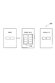
- FIG. 3 is a diagram illustrating the layer 2 buffer 240. As shown in FIG. 3, the layer 2 buffer 240 is logically divided into an uplink (UL) data storage unit 241 and a downlink (DL) data storage unit 243.
- UL uplink
- DL downlink
- UL data storage unit 241 temporarily stores UL data transmitted from the terminal 200 to the communication nodes 100a and 100b. Examples of UL data temporarily stored in the UL data storage unit 241 include the following data.
- the UL data storage unit 241 stores UL data for each wireless bearer. ing. Specifically, the UL data communicated by the wireless bearer 1 is stored in the area 241a. UL data communicated by the wireless bearer 2 is stored in area 241b.
- the UL data is associated with the wireless bearer to which the UL data is transmitted in the UL data storage unit 241, it is not necessary to store the UL data for each wireless bearer.
- the terminal 200 can acquire the retention state of UL data stored in the layer 2 buffer 240 for each wireless bearer.
- the terminal 200 Before transmitting the buffer status report (BSR) to the communication node, the terminal 200 is stored in the area in the UL data storage unit 241 corresponding to the wireless bearer set between the terminal 200 and the communication node. Acquire the retention amount of UL data. The terminal 200 transmits the retained amount of the acquired UL data to the communication node using the BSR.
- BSR buffer status report
- the communication node When the communication node receives the BSR from the terminal 200, it sends a UL permit (UL grant) to the terminal 200 and allocates wireless resources for UL data transmission. Upon receiving the UL grant, the terminal 200 can transmit UL data to the communication node using the allocated radio resource. Therefore, in the case of UL data transmission by grant allocation, it is essential to store UL data before transmission processing is performed in the PDCP layer.
- UL grant UL permit
- the DL data storage unit 243 temporarily stores the DL data transmitted from the communication nodes 100a and 100b to the terminal 200.
- Examples of DL data temporarily stored in the DL data storage unit include the following data.
- the DL data storage unit 243 stores DL data for each wireless bearer. Specifically, the DL data communicated by the wireless bearer 1 is stored in the area 243a. The DL data communicated by the wireless bearer 2 is stored in the area 243b.
- the DL data storage unit 243 if the DL data is associated with the wireless bearer to which the DL data is transmitted, it is not necessary to store the DL data for each wireless bearer.
- the terminal 200 can acquire the retention state of the DL data stored in the layer 2 buffer 240 for each wireless bearer.
- the sizes of the areas 241a and 241b in the UL data storage unit 241 and the areas 243a and 243b of the DL data storage unit 243 are not fixed, and the UL data and DL communicated by each wireless bearer are not fixed. It can fluctuate dynamically depending on the amount of data retained.
- the communication node 100a is not the amount of data retained in the areas 241a and 243a in which the UL data and DL data communicated by the wireless bearer 1 are stored, but the data retained in the layer 2 buffer 240. Transmission control is performed based on the total retention amount of.
- the communication node 100b is not the amount of data retained in the areas 241b and 243b where the UL data and DL data communicated by the wireless bearer 2 are stored, but the total amount of data retained in the layer 2 buffer 240. Transmission control is performed based on.
- the terminal 200 When an overflow occurs in the layer 2 buffer 240, the terminal 200 performs the following operations, for example.
- the data communicated by the wireless bearers 1 and 2 used for DC is temporarily stored in the layer 2 buffer 240, as will be described later.
- the transmission control is performed for the terminal 200 by grasping the current state.
- FIG. 4 is a functional block configuration diagram of communication nodes 100a and 100b. Since the communication nodes 100a and 100b have the same configuration, the description of the communication node 100b will be omitted.
- the communication node 100a includes a transmission unit 110, a reception unit 120, a timer 130, a management unit 140, and a control unit 150.
- the transmission unit 110 transmits DL data using the wireless bearer 1 set between the communication node 100a and the terminal 200. For example, the transmission unit 110 transmits new DL data to the terminal 200 based on the transmission control by the control unit 150.
- the data communicated by the wireless bearer 1 is retained in the layer 2 buffer 240 in the “procedure for transmitting retention information between the communication nodes 100a and 100b” (see FIG. 8) described later.
- the retention information indicating the status is transmitted to the communication node 100b.
- the data communicated by the wireless bearer 2 is buffered in the layer 2 in the “procedure for transmitting the retention information between the communication nodes 100a and 100b” (see FIG. 8) described later.
- the retention information indicating the status of retention at 240 is transmitted to the communication node 100a.
- the receiving unit 120 receives UL data using the wireless bearer 1 set between the communication node 100a and the terminal 200. For example, the receiving unit 120 receives the BSR from the terminal 200.
- the receiving unit 120 retains the data communicated by the wireless bearers 1 and 2 in the layer 2 buffer 240.
- the retention information indicating the status is received from the terminal 200.
- the receiving unit 120 indicates a state in which the data communicated by the wireless bearer 2 is retained in the layer 2 buffer 240 in the “procedure for transmitting retention information between the communication nodes 100a and 100b” (see FIG. 8) described later.
- the retention information is received from the communication node 100b.
- the timer 130 is used to determine whether or not to transmit the retention information when the retention information is periodically transmitted.
- the management unit 140 manages the retention information received from the terminal 200 in association with the wireless bearers 1 and 2 in the “procedure for transmitting retention information between the communication node 100a and the terminal 200” (see FIG. 6) described later. To do.
- the management unit 140 manages the retention information estimated by the communication node 100a in association with the wireless bearer 1 in the “procedure for transmitting retention information between the communication nodes 100a and 100b” (see FIG. 8), which will be described later, and also manages the retention information.
- the residence information received from the communication node 100b is managed in association with the wireless bearer 2.
- the control unit 150 performs processing at the layer 2 level.
- the control unit 150 controls transmission of new DL data based on the retention information acquired from the terminal 200 in the “procedure for transmitting retention information between the communication node 100a and the terminal 200” (see FIG. 6), which will be described later. I do.
- the control unit 150 indicates a state in which the data communicated by the wireless bearer 1 is retained in the layer 2 buffer 240 in the “procedure for transmitting retention information between the communication nodes 100a and 100b” (see FIG. 8) described later. Estimate retention information. The control unit 150 instructs the transmission unit 110 to transmit the estimated retention information to the communication node 100b based on a specific trigger.
- the control unit 150 is based on the retention information estimated by the control unit 150 and the retention information acquired from the communication node 100b in the "procedure for transmitting retention information between the communication nodes 100a and 100b" (see FIG. 8) described later. Then, the transmission of new DL data is controlled.
- control unit 150 uses the timer 130 to determine that a predetermined time has elapsed since the transmission of the retention information, the control unit 150 instructs the transmission unit 110 to transmit the new retention information to the communication node 100b.
- the control unit 150 acquires the retention information associated with each wireless bearer from the management unit 140 when performing transmission control.
- FIG. 5 is a functional block configuration diagram of the terminal 200. As shown in FIG. 5, the terminal 200 includes a transmission unit 210, a reception unit 220, a timer 230, a layer 2 buffer 240, and a control unit 250.
- the transmission unit 210 transmits UL data using the wireless bearer 1 set between the communication node 100a and the terminal 200.
- the transmission unit 210 transmits UL data using the wireless bearer 2 set between the communication node 100b and the terminal 200.
- the transmission unit 210 receives the BSR to the communication nodes 100a and 100b.
- the transmission unit 210 retains the data communicated by the wireless bearers 1 and 2 in the layer 2 buffer 240.
- the retention information indicating the status is transmitted to the communication nodes 100a and 100b.
- the receiving unit 220 receives DL data using the wireless bearer 1 set between the communication node 100a and the terminal 200.
- the transmission unit 210 receives DL data by using the wireless bearer 2 set between the communication node 100b and the terminal 200.
- the receiving unit 220 receives new DL data from the communication nodes 100a and 100b based on the transmission control by the communication nodes 100a and 100b.
- the timer 230 is used to determine whether or not to transmit the retention information when the retention information is periodically transmitted.
- the layer 2 buffer 240 temporarily stores UL data and DL data for each wireless bearer.
- Control unit 250 performs processing at the layer 2 level.
- the control unit 250 retains the data communicated by the wireless bearers 1 and 2 in the layer 2 buffer 240. Acquires retention information indicating the status of the node. The control unit 250 instructs the transmission unit 210 to transmit the acquired retention information to the communication nodes 100a and 100b based on a specific trigger.
- the control unit 250 instructs the transmission unit 210 to transmit the retention information indicating the state in which the data communicated by the wireless bearer 1 is retained in the layer 2 buffer 240 to the communication node 100a using the BSR. Similarly, the control unit 250 sends the retention information indicating the state in which the data communicated by the wireless bearer 2 is retained in the layer 2 buffer 240 to the transmission unit 210 so as to be transmitted to the communication node 100b using the BSR. Instruct.
- control unit 250 uses the timer 230 to determine that a predetermined time has elapsed from the transmission of the retention information, the control unit 250 instructs the transmission unit 210 to transmit the new retention information to the communication nodes 100a and 100b.
- the layer 2 buffer 240 of the terminal 200 temporarily stores the data communicated by the wireless bearers 1 and 2. This state is also expressed as the data communicated by the wireless bearers 1 and 2 staying in the layer 2 buffer 240.
- each of the communication nodes 100a and 100b grasps the state in which the data communicated by the wireless bearers 1 and 2 is accumulated in the layer 2 buffer 240 in the DC. , The operation of performing transmission control for the terminal 200 will be described.
- the terminal 200 communicates with the communication nodes 100a and 100b by the wireless bearers 1 and 2, and the data communicated by the wireless bearers 1 and 2 is the layer 2 buffer 240. A case of reporting the retention information indicating the state of retention in is described.
- the retention information layer 2 buffer 240 is logically divided into UL data storage unit 241 and DL data storage unit 243 (see FIG. 3).
- the retention information for example, the following information can be mentioned.
- the total amount of UL data accumulated in the UL data storage unit 241 and the total amount of DL data accumulated in the DL data storage unit 243 (hereinafter referred to as the total accumulated data amount).
- -Ratio of the total amount of accumulated data to the total capacity of data that can be stored in the UL data storage unit 241 and DL data storage unit 243 (hereinafter referred to as the total buffer size)
- -UL data storage unit 241 and DL data storage unit 243 free space hereinafter referred to as the free space of all buffers
- -Total amount of accumulated data and total buffer size-Flag indicating whether or not the terminal 200 can receive new data
- the terminal 200 is used in all the wireless bearers 1 and 2 used for DC.
- the retention information indicating the retention state of all the data retained in the layer 2 buffer 240 is transmitted to each communication node.
- FIG. 6 is a diagram showing an example of a sequence of procedures for transmitting retention information by the communication nodes 100a and 100b and the terminal 200.
- the terminal 200 when the terminal 200 detects a specific trigger (S11), the terminal 200 provides the retention information indicating the retention state of the data retained in the layer 2 buffer 240 in all the wireless bearers used for the DC. Get (S13).
- the network (for example, communication nodes 100a, 100b) has one or more of the above-mentioned events. , Wireless bearer unit, RLC bearer unit, RLC channel unit, LCH unit, quality of service (QoS) unit, or a unit obtained by grouping some of these units, which is preset in the terminal 200. You may. In this case, the terminal 200 may transmit the acquired retention information to the communication nodes 100a and 100b when at least one event among the preset events is detected.
- QoS quality of service
- the network (for example, communication nodes 100a, 100b) can perform two or more of the above-mentioned events in units of wireless bearers, units of RLC bearers, units of RLC channels, units of LCH, and quality of service (QoS). ) Units, or units in which some of these units are grouped, may be preset in the terminal 200. In this case, the terminal 200 may transmit the acquired retention information to the communication nodes 100a and 100b when all the preset events are detected.
- QoS quality of service
- the terminal 200 When the terminal 200 acquires the retention information based on the detection of a specific trigger, the terminal 200 transmits the acquired retention information to the communication nodes 100a and 100b (S15).
- the terminal 200 may include the residence information in the RRC message, MAC CE or L1 signal and transmit it to the communication nodes 100a and 100b.
- the terminal 200 may include the retention information in a PDCP / control / protocol / data unit (PDU) such as a PDCP status report and transmit it to the communication nodes 100a and 100b.
- PDU protocol / data unit
- the terminal 200 transmits the retention information in a wireless bearer unit, an RLC bearer unit, an RLC channel unit, an LCH unit, a quality of service (QoS) unit, or a unit obtained by grouping some of these units. You may.
- the communication nodes 100a and 100b When each of the communication nodes 100a and 100b receives the retention information from the terminal 200, the communication nodes 100a and 100b perform transmission control to the terminal 200 (S17). Specifically, when each of the communication nodes 100a and 100b transmits new DL data based on the retention information received from the terminal 200, the layer 2 buffer 240 of the terminal 200 may overflow. Decide whether or not.
- each of the communication nodes 100a and 100b sends new DL data to the terminal 200.
- each of the communication nodes 100a and 100b stops transmitting new DL data to the terminal 200.
- each of the communication nodes 100a and 100b has new DL data for the terminal 200. Stop sending. Further, when the free space of all the received buffers falls below the threshold value, each of the communication nodes 100a and 100b stops transmitting new DL data to the terminal 200. Further, when the received flag indicates that the new data cannot be received, each of the communication nodes 100a and 100b stops the transmission of the new DL data to the terminal 200.
- FIG. 7 is a diagram showing an example of an operation flow of the transmission processing of the retention information by the terminal 200.
- the terminal 200 when the terminal 200 acquires the retention information based on the detection of a specific trigger, the terminal 200 transmits the retention information to the communication nodes 100a and 100b (S21). After transmitting the retention information, the terminal 200 determines whether or not a predetermined time has elapsed from the transmission of the retention information (S23).
- the terminal 200 determines that the predetermined time has elapsed, it acquires new retention information and transmits the new retention information to the communication nodes 100a and 100b (S25). On the other hand, when the terminal 200 determines that the predetermined time has not elapsed, the terminal 200 waits until the predetermined time elapses.
- the terminal 200 When the terminal 200 transmits new retention information, it determines whether or not to end the transmission of retention information (S27). If the transmission of the retention information is not completed, the operation of the terminal 200 returns to S23. On the other hand, when the transmission of the retention information is terminated, the terminal 200 ends the transmission of the retention information.
- the terminal 200 transmits the retention information to the communication nodes 100a and 100b at predetermined time intervals.
- the communication node 100a estimates and estimates the retention information indicating the state in which the data communicated by the wireless bearer 1 is retained in the layer 2 buffer 240.
- a case of reporting the accumulated retention information to the communication node 100b will be described. In this case, although the description is omitted, the communication node 100b is also estimated by estimating the retention information indicating the state in which the data communicated by the wireless bearer 2 is retained in the layer 2 buffer 240. Report the retention information to the communication node 100a.
- the amount of retained data -The ratio of the amount of retained data to the data capacity (hereinafter referred to as the buffer size) that can be stored in the area 241a of the UL data storage unit 241 and the area 243a of the DL data storage unit 243.-The area 241a of the UL data storage unit 241. And the free space in the area 243a of the DL data storage unit 243 (hereinafter referred to as the free space in the buffer).
- -Amount of stagnant data and buffer size-Flag indicating whether the terminal 200 can receive new data (3.2.3) Estimate of stagnant information at each communication node Next, estimate of stagnant information at communication node 100a The method will be explained.
- the communication node 100a is the PDCP layer that performs Reordering processing, and based on the BSR transmitted from the terminal 200, the amount of UL data retained in the area 241a of the UL data storage unit 241 (hereinafter referred to as the accumulated UL data amount). ) Is estimated.
- the terminal 200 is a communication node in which the primary path 2a is set by using the BSR when the accumulated UL data amount is less than the threshold value (for example, ul-DataSplitThreshold notified by the RRC message).
- the amount of accumulated UL data is transmitted for 100b.
- the terminal 200 uses the BSR to transmit the value 0 to the communication node 100a in which the secondary path 2b is set.
- the communication node 100a is the area 243a of the DL data storage unit 243 based on the amount of DL data transmitted to the terminal 200 in the PDCP layer that performs the Reordering process and has not received the delivery confirmation in the correct order.
- Estimate the amount of DL data accumulated in hereinafter referred to as the amount of accumulated DL data).
- the communication node 100a estimates the retention information based on the retention UL data amount and the retention DL data amount. For example, the communication node 100a estimates the amount of stagnant data by adding the amount of stagnant UL data and the amount of stagnant DL data.
- the communication node 100a can estimate the residence information in the wireless bearer 1 set between the terminal 200 and the communication node 100a. In this case, the communication node 100a cannot estimate the residence information in the wireless bearer set between the terminal 200 and the communication node 100b.
- FIG. 8 is a diagram showing an example of a sequence of procedures for transmitting retention information by the communication nodes 100a and 100b.
- the communication node 100a transmits the retention information to the communication node 100b.
- the communication node 100a detects a specific trigger (S31), among the wireless bearers 1 and 2 used for DC, the data retained in the layer 2 buffer 240 in the wireless bearer 1 Estimate the retention information indicating the retention state of (S33).
- the following event can be mentioned as a specific trigger in S31.
- the above-mentioned retention information report instruction message may be included in the Xn signal.
- the wireless communication system 10 includes E-UTRAN, the above-mentioned retention information report instruction message may be included in the X2 signal.
- the predetermined time and threshold value described above may be preset from the network (for example, the communication node 100b).
- the network may preset one or more events in the communication node 100a among the plurality of events described above.
- the communication node 100a may transmit the estimated retention information to the communication node 100b when at least one of the preset events is detected.
- the network may preset two or more events in the communication node 100a among the plurality of events described above.
- the communication node 100a may transmit the estimated retention information to the communication node 100b when all the preset events are detected.
- the communication node 100a When the communication node 100a estimates the retention information based on the detection of a specific trigger, the communication node 100a transmits the acquired retention information to the communication node 100b (S35).
- the communication node 100a may be included in the data delivery status message (DDDS) and transmitted to the communication node 100b.
- the communication node 100a, along with the retention information, is the value of the quality information of the wireless bearer 1 (eg, measurement report, channel state information (CSI), power headroom (PHR), etc.), the UE capability of the terminal 200 such as the UE category. Etc. may be reported.
- the quality information of the wireless bearer 1 eg, measurement report, channel state information (CSI), power headroom (PHR), etc.
- PHR power headroom
- Etc. may be reported.
- the communication node 100a may independently transmit the UL retention information estimated based on the retention UL data amount and the DL retention information estimated based on the retention DL data amount to the communication node 100b.
- the communication node 100b may independently transmit the UL retention information report instruction message and the DL retention information report message.
- the communication node 100b When the communication node 100b receives the retention information from the communication node 100a, the communication node 100b performs transmission control to the terminal 200 (S37). Specifically, when the communication node 100b transmits new DL data based on the retention information in the wireless bearer 1 received from the communication node 100a and the retention information in the wireless bearer 2 estimated by the communication node 100b. , Determines if the layer 2 buffer 240 of the terminal 200 may overflow.
- the communication node 100b If there is no possibility of overflow, the communication node 100b sends new DL data to the terminal 200. On the other hand, when there is a possibility of overflow, the communication node 100b stops transmitting new DL data to the terminal 200.
- the specific determination method is the same as the determination method described in "(3.1.2) Procedure for transmitting retention information" above.
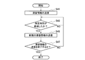
- FIG. 9 is a diagram showing an example of an operation flow of the transmission processing of the retention information by the communication node 100a.
- the communication node 100a when the communication node 100a estimates the retention information based on the detection of a specific trigger, the communication node 100a transmits the retention information to the communication node 100b (S41). After transmitting the retention information, the communication node 100a determines whether or not a predetermined time has elapsed from the transmission of the retention information (S43).
- the communication node 100a determines that the predetermined time has elapsed, it estimates the new retention information and transmits the new retention information to the communication node 100b (S45). On the other hand, when the communication node 100a determines that the predetermined time has not elapsed, the communication node 100a waits until the predetermined time elapses.
- the communication node 100a When the communication node 100a transmits new retention information, it determines whether or not to end the transmission of retention information (S47). If the transmission of the retention information is not completed, the operation of the communication node 100a returns to S43. On the other hand, when the transmission of the retention information is terminated, the communication node 100a ends the transmission of the retention information.
- the communication node 100a transmits the retention information to the communication node 100b at predetermined time intervals.
- the state variable of the PDCP layer or the RLC layer may be used instead of the amount of data.
- the terminal 200 may be notified from the network (for example, communication nodes 100a, 100b) which of the PDCP layer state variables and the RLC layer state variables is used as the retention information.
- FIG. 10 is a diagram for explaining a modification of the retention information. As shown in FIG. 10, in the terminal 200, four packets are accumulated in the layer 2 buffer 240, specifically, the area 243a of the DL data storage unit 243.
- the packet contains the count value.
- the count value has a hyperframe number (HFN) and a PDCP-sequence number (SN).
- HFN hyperframe number
- SN PDCP-sequence number
- the PDCP-SN is incremented on the transmitting side each time a packet is sent from the PDCP layer to the RLC layer.
- the HFN is incremented on the transmitting side each time the PDCP-SN goes around.
- Values 1 to 4 are assigned to the PDCP-SN of the four packets stored in the layer 2 buffer 240.
- a value of 0 is assigned to the PDCP-SN of the packet finally sent to the upper layer.
- the PDCP layer sends PDCP packets to the upper layer using the set RX_DELIV.
- a value of 5 is assigned to PDCP-SN of the packet expected to be sent to the layer 2 buffer 240.
- the PDCP layer receives the packet using the set RX_NEXT.
- the retention information includes PDCP-SN of the packet sent to the last upper layer and PDCP-SN of the packet retained in the layer 2 buffer 240. Notifies the largest value of SN.
- the terminal 200 transmits the PDCP-SN values 0 and 4 to the communication node 100a as residence information.
- the communication node 100a estimates that four PDCP packets are accumulated in the layer 2 buffer 240 based on the received PDCP-SN values 0 and 4.
- the terminal 200 When the terminal 200 detects a specific trigger, it is expected that the smallest value of the PDCP-SN of the packets staying in the layer 2 buffer 240 and then the transmission to the layer 2 buffer 240 are sent as the retention information. It may notify the PDCP-SN of the packet. The packet with the lowest value PDCP-SN is then sent to the higher layer. Specifically, the terminal 200 may transmit PDCP-SN values 1 and 5 to the communication node 100a as residence information.
- the above-mentioned packet may be, for example, a service data unit (SDU) or a packet data unit (PDU) in the PDCP layer or the RLC layer.
- the terminal 200 may use PDCP-SN, HFN, a count value, or the like instead of PDCP-SN.
- the terminal 200 has, as retention information, the number of PDCP SDU, PDCP PDU, RLC SDU, RLC PDU, SDPA SDU or SDPA PDU retained in the layer 2 buffer, average data size, maximum data size, minimum data size, Statistical information and the like may be transmitted to the communication nodes 100a and 100b.
- each communication node transmits, for example, PDCP-SN, PDCP-SN and HFN of the packet, count value, and the like as retention information to other communication nodes.
- the content of the retention information used in the above-mentioned "(3.1) Report of retention information between the terminal and the communication node” and "(3.2) Report of retention information between the communication nodes" is set from the network. You may.
- the retention information used in the above-mentioned "(3.1) Report of retention information between terminal and communication node” and "(3.2) Report of retention information between communication nodes” is the retention information for UL and the retention information. It may be divided into the retention information for DL and transmitted individually.
- the retention information used in the above-mentioned "(3.1) Report of retention information between terminal and communication node” and "(3.2) Report of retention information between communication nodes" is divided for each QoS. It may be sent individually.
- the terminal 200 transmits UL data and DL data communicated using the wireless bearers 1 and 2 set between the terminal 200 and the communication nodes 100a and 100b.
- Information indicating the retention state of all the data retained in the stored layer 2 buffer 240 is transmitted to the communication nodes 100a and 100b based on a specific trigger.
- the communication nodes 100a and 100b can grasp the total amount of accumulated data in the wireless bearers 1 and 2, so that appropriate transmission control can be performed. Therefore, the terminal 200 can surely prevent the occurrence of overflow in the layer 2 buffer 240.
- the terminal 200 uses the layer 2 buffer 240 in the layer 2 buffer 240. Since the occurrence of overflow can be reliably prevented, deterioration of communication quality, occurrence and increase of communication delay, and reduction of throughput can be avoided in the wireless communication system 10.
- the terminal 200 transmits information indicating the retention state to the communication nodes 100a and 100b at regular time intervals.
- the communication nodes 100a and 100b can periodically grasp the retention state of the data retained in the layer 2 buffer 240, so that more appropriate transmission control can be performed. Therefore, the terminal 200 can more reliably prevent the occurrence of overflow in the layer 2 buffer 240.
- the communication node 100a is stored in the layer 2 buffer 240 of the terminal 200 that stores UL data and DL data communicated by using the wireless bearer 1 set between the terminal 200 and the communication node 100a.
- Information indicating the retention state of the retention data is transmitted to the communication node 100b based on a specific trigger.
- the communication node 100b can grasp the amount of accumulated data in the wireless bearer 1 set between the communication node 100a and the terminal 200.
- the communication node 100b stores the UL data and DL data communicated by the wireless bearer 2 set between the terminal 200 and the communication node 100b, and the data staying in the layer 2 buffer 240 of the terminal 200 is retained.
- Information indicating the state is transmitted to the communication node 100a based on a specific trigger.
- the communication node 100a can grasp the amount of accumulated data in the wireless bearer 2 set between the communication node 100b and the terminal 200.
- the communication nodes 100a and 100b can grasp the total amount of accumulated data in the wireless bearers 1 and 2, so that appropriate transmission control can be performed. Therefore, the communication nodes 100a and 100b can surely prevent the occurrence of overflow in the layer 2 buffer 240 of the terminal 200.
- the communication node 100a transmits information indicating the retention state to the communication node 100b at regular time intervals.
- the communication node 100b transmits information indicating the retention state to the communication node 100a at regular intervals.
- the communication nodes 100a and 100b can periodically grasp the retention state of the data retained in the layer 2 buffer 240, so that more appropriate transmission control can be performed. Therefore, the communication nodes 100a and 100b can more reliably prevent the occurrence of overflow in the layer 2 buffer 240 of the terminal 200.
- the terminal 200 is provided with the layer 2 buffer 240 including the UL data storage unit 241 and the DL data storage unit 243, but the configuration of the layer 2 buffer is not limited to this.
- a layer 2 buffer for UL data and a layer 2 buffer for DL data may be provided separately.
- each of the communication nodes 100a and 100b grasps the state in which the DL data communicated by all the wireless bearers 1 and 2 used for the DC is temporarily stored in the layer 2 buffer for the DL data.
- Transmission control may be performed on the terminal 200.
- the terminal 200 communicates using the wireless resources provided by the communication nodes 100a and 100b, but the number of communication nodes is not limited to this.
- the terminal 200 may communicate using wireless resources provided by three or more communication nodes.
- each communication node transmits the retention information to the other two communication nodes.
- the retention information is reported between the communication nodes 100a and 100b, but the reporting of the retention information between the communication nodes is not limited to this.
- the communication node is functionally separated into an aggregate node (CU) and a distributed node (DU)
- retention information may be reported between the CU and DU via the F1 interface.
- the CU of the communication node is functionally separated into the CU-CP that terminates the control plane and the CU-UP that terminates the user plane, it stays between the CU-CP and CU-UP via the E1 interface. Information may be reported.
- the retention information may be collected in any communication node among the plurality of communication nodes. ..
- the terminal 200 may individually transmit the retention information of each layer. Further, the terminal 200 may collectively transmit the retention information of a plurality of layers.
- the layer to be transmitted may be limited to a layer having a buffer function (for example, a PDCP layer and an RLC layer).
- the terminal 200 when the terminal 200 implements another buffer (for example, a MAC buffer) in addition to the layer 2 buffer, the accumulated data amount of the other buffer is added to the total retention of the layer 2 buffer. It may or may not be added to the amount of data. In this case, the terminal 200 may notify the communication nodes 100a and 100b whether or not to add the accumulated data amount of another buffer to the total accumulated data amount of the layer 2 buffer.
- another buffer for example, a MAC buffer
- the particle size and accuracy of the data (for example, bytes, kilobytes, megabytes, or an indicator indicating the amount of data) in the transmission of the retention information by the terminal 200 may be different for each layer to be transmitted. .. In this case, the particle size and accuracy of the data may be specified by the network.
- the network may hold information about whether or not the terminal 200 has the following capabilities.
- information about whether or not the terminal 200 has the following capabilities may be reported to the network (for example, communication nodes 100a, 100b).
- the ability to report retention information may include the message type used for reporting.
- Message types include, for example, RRC messages, PDCP control PDUs such as PDCP status reports, MAC CE, and L1 signals.
- the ability to report retention information may include reportable information types, reportable particle size, methods for reporting retention information, and the like.
- Reportable particle size includes reportability for each layer, reportability for each layer and between layers, data granularity and accuracy (for example, bytes, kilobytes, or megabytes), reportability for UL and DL, and reporting for each QoS. Whether or not it is possible.
- the ability to set a specific trigger may include the number of triggers that can be set, the type of trigger that can be set, and the like.
- each functional block may be realized by using one device that is physically or logically connected, or directly or indirectly (for example, by using two or more physically or logically separated devices). , Wired, wireless, etc.) and may be realized using these plurality of devices.
- the functional block may be realized by combining the software with the one device or the plurality of devices.
- Functions include judgment, decision, judgment, calculation, calculation, processing, derivation, investigation, search, confirmation, reception, transmission, output, access, solution, selection, selection, establishment, comparison, assumption, expectation, deemed, and notification (There are, but are not limited to, broadcasting, notifying, communicating, forwarding, configuring, reconfiguring, allocating, mapping, assigning, etc. ..
- a functional block that makes transmission function is called a transmitting unit or a transmitter.
- the method of realizing each is not particularly limited.
- FIG. 11 is a diagram showing an example of the hardware configuration of the communication node and the terminal.
- the communication node and the terminal may be configured as a computer device including a processor 1001, a memory 1002, a storage 1003, a communication device 1004, an input device 1005, an output device 1006, a bus 1007, and the like.
- the word “device” can be read as a circuit, device, unit, etc.
- the hardware configuration of the device may be configured to include one or more of the devices shown in the figure, or may be configured not to include some of the devices.
- Each functional block of the device is realized by any hardware element of the computer device or a combination of the hardware elements.
- the processor 1001 performs the calculation, controls the communication by the communication device 1004, and the memory. It is realized by controlling at least one of reading and writing of data in 1002 and storage 1003.
- Processor 1001 operates, for example, an operating system to control the entire computer.
- the processor 1001 may be composed of a central processing unit (CPU) including an interface with peripheral devices, a control device, an arithmetic unit, registers, and the like.
- CPU central processing unit
- the processor 1001 reads a program (program code), a software module, data, etc. from at least one of the storage 1003 and the communication device 1004 into the memory 1002, and executes various processes according to these.
- a program program code
- a program that causes a computer to execute at least a part of the operations described in the above-described embodiment is used.
- the various processes described above may be executed by one processor 1001 or may be executed simultaneously or sequentially by two or more processors 1001.
- Processor 1001 may be implemented by one or more chips.
- the program may be transmitted from the network via a telecommunication line.
- the memory 1002 is a computer-readable recording medium, and is composed of at least one such as ReadOnlyMemory (ROM), ErasableProgrammableROM (EPROM), Electrically ErasableProgrammableROM (EEPROM), and RandomAccessMemory (RAM). May be done.
- the memory 1002 may be called a register, a cache, a main memory (main storage device), or the like.
- the memory 1002 can store a program (program code), a software module, or the like that can execute the method according to the embodiment of the present disclosure.
- the storage 1003 is a computer-readable recording medium, for example, an optical disk such as Compact Disc ROM (CD-ROM), a hard disk drive, a flexible disk, an optical magnetic disk (for example, a compact disk, a digital versatile disk, or a Blu-ray). It may consist of at least one (registered trademark) disk), smart card, flash memory (eg, card, stick, key drive), floppy (registered trademark) disk, magnetic strip, and the like.
- Storage 1003 may be referred to as auxiliary storage.
- the recording medium described above may be, for example, a database, server or other suitable medium containing at least one of the memory 1002 and the storage 1003.
- the communication device 1004 is hardware (transmission / reception device) for communicating between computers via at least one of a wired network and a wireless network, and is also referred to as, for example, a network device, a network controller, a network card, a communication module, or the like.
- Communication device 1004 includes, for example, a high frequency switch, a duplexer, a filter, a frequency synthesizer, etc. in order to realize at least one of frequency division duplex (FDD) and time division duplex (TDD). It may be composed of.
- FDD frequency division duplex
- TDD time division duplex
- the input device 1005 is an input device (for example, keyboard, mouse, microphone, switch, button, sensor, etc.) that accepts input from the outside.
- the output device 1006 is an output device (for example, a display, a speaker, an LED lamp, etc.) that outputs to the outside.
- the input device 1005 and the output device 1006 may have an integrated configuration (for example, a touch panel).
- each device such as the processor 1001 and the memory 1002 is connected by the bus 1007 for communicating information.
- the bus 1007 may be configured by using a single bus, or may be configured by using a different bus for each device.
- the device includes hardware such as a microprocessor, a digital signal processor (Digital Signal Processor: DSP), an Application Specific Integrated Circuit (ASIC), a Programmable Logic Device (PLD), and a Field Programmable Gate Array (FPGA).
- the hardware may implement some or all of each functional block.
- processor 1001 may be implemented using at least one of these hardware.
- information notification includes physical layer signaling (for example, Downlink Control Information (DCI), Uplink Control Information (UCI), upper layer signaling (eg, RRC signaling, Medium Access Control (MAC) signaling, broadcast information (Master Information Block)). (MIB), System Information Block (SIB)), other signals or combinations thereof.
- DCI Downlink Control Information
- UCI Uplink Control Information
- RRC signaling may also be referred to as an RRC message, for example, RRC Connection Setup. ) Message, RRC Connection Reconfiguration message, etc. may be used.
- LTE LongTermEvolution
- LTE-A LTE-Advanced
- SUPER3G IMT-Advanced
- 4G 4th generation mobile communication system
- 5G 5th generation mobile communication system
- FutureRadioAccess FAA
- NewRadio NR
- W-CDMA registered trademark
- GSM registered trademark
- CDMA2000 Code Division Multiple Access 2000
- UMB UltraMobile Broadband
- IEEE802.11 Wi-Fi (registered trademark)
- IEEE802.16 WiMAX®
- IEEE802.20 Ultra-WideBand (UWB), Bluetooth®, and other systems that utilize appropriate systems and at least one of the next generation systems extended based on them.
- a plurality of systems may be applied in combination (for example, a combination of at least one of LTE and LTE-A and 5G).
- the specific operation performed by the base station in the present disclosure may be performed by its upper node (upper node).
- various operations performed for communication with the terminal are performed by the base station and other network nodes other than the base station (for example, MME or). It is clear that it can be done by at least one of (but not limited to, S-GW, etc.).
- S-GW network nodes
- the case where there is one network node other than the base station is illustrated above, it may be a combination of a plurality of other network nodes (for example, MME and S-GW).
- Information and signals can be output from the upper layer (or lower layer) to the lower layer (or upper layer).
- Input / output may be performed via a plurality of network nodes.
- the input / output information may be stored in a specific location (for example, memory) or may be managed using a management table.
- the input / output information can be overwritten, updated, or added.
- the output information may be deleted.
- the input information may be transmitted to another device.
- the determination may be made by a value represented by 1 bit (0 or 1), by a boolean value (Boolean: true or false), or by comparing numerical values (for example, a predetermined value). It may be done by comparison with the value).
- the notification of predetermined information (for example, the notification of "being X") is not limited to the explicit one, but is performed implicitly (for example, the notification of the predetermined information is not performed). May be good.
- Software is an instruction, instruction set, code, code segment, program code, program, subprogram, software module, whether called software, firmware, middleware, microcode, hardware description language, or another name.
- Applications, software applications, software packages, routines, subroutines, objects, executable files, execution threads, procedures, features, etc. should be broadly interpreted to mean.
- software, instructions, information, etc. may be transmitted and received via a transmission medium.
- a transmission medium For example, a website where the software uses at least one of wired technology (coaxial cable, fiber optic cable, twisted pair, Digital Subscriber Line (DSL), etc.) and wireless technology (infrared, microwave, etc.).
- wired technology coaxial cable, fiber optic cable, twisted pair, Digital Subscriber Line (DSL), etc.
- wireless technology infrared, microwave, etc.
- the information, signals, etc. described in this disclosure may be represented using any of a variety of different techniques.
- data, instructions, commands, information, signals, bits, symbols, chips, etc. that may be referred to throughout the above description are voltages, currents, electromagnetic waves, magnetic fields or magnetic particles, light fields or photons, or any of these. It may be represented by a combination of.
- a channel and a symbol may be a signal (signaling).
- the signal may be a message.
- the component carrier (CC) may be referred to as a carrier frequency, a cell, a frequency carrier, or the like.
- system and “network” used in this disclosure are used interchangeably.
- the information, parameters, etc. described in the present disclosure may be expressed using absolute values, relative values from predetermined values, or using other corresponding information. It may be represented.
- the radio resource may be one indicated by an index.
- Base Station BS
- Wireless Base Station Wireless Base Station
- NodeB NodeB
- eNodeB eNodeB
- gNodeB gNodeB
- Base stations are sometimes referred to by terms such as macrocells, small cells, femtocells, and picocells.
- the base station can accommodate one or more (for example, three) cells (also called sectors). When a base station accommodates multiple cells, the entire coverage area of the base station can be divided into multiple smaller areas, each smaller area being a base station subsystem (eg, a small indoor base station (Remote Radio)). Communication services can also be provided by Head: RRH).
- a base station subsystem eg, a small indoor base station (Remote Radio)
- Communication services can also be provided by Head: RRH).
- cell refers to a base station that provides communication services in this coverage, and part or all of the coverage area of at least one of the base station subsystems.
- MS mobile station
- UE user equipment
- terminal terminal
- Mobile stations can be subscriber stations, mobile units, subscriber units, wireless units, remote units, mobile devices, wireless devices, wireless communication devices, remote devices, mobile subscriber stations, access terminals, mobile terminals, wireless, depending on the trader. It may also be referred to as a terminal, remote terminal, handset, user agent, mobile client, client, or some other suitable term.
- At least one of the base station and the mobile station may be called a transmitting device, a receiving device, a communication device, or the like.
- At least one of the base station and the mobile station may be a device mounted on the mobile body, the mobile body itself, or the like.
- the moving body may be a vehicle (eg, car, airplane, etc.), an unmanned moving body (eg, drone, self-driving car, etc.), or a robot (manned or unmanned). ) May be.
- at least one of the base station and the mobile station includes a device that does not necessarily move during communication operation.
- at least one of a base station and a mobile station may be an Internet of Things (IoT) device such as a sensor.
- IoT Internet of Things
- the base station in the present disclosure may be read as a mobile station (user terminal, the same applies hereinafter).
- communication between a base station and a mobile station has been replaced with communication between a plurality of mobile stations (for example, it may be called Device-to-Device (D2D), Vehicle-to-Everything (V2X), etc.).
- D2D Device-to-Device
- V2X Vehicle-to-Everything
- Each aspect / embodiment of the present disclosure may be applied to the configuration.
- the mobile station may have the function of the base station.
- words such as "up” and “down” may be read as words corresponding to communication between terminals (for example, "side”).
- the uplink, downlink, and the like may be read as side channels.
- the mobile station in the present disclosure may be read as a base station.
- the base station may have the functions of the mobile station.
- connection means any direct or indirect connection or connection between two or more elements, and each other. It can include the presence of one or more intermediate elements between two “connected” or “combined” elements.
- the connection or connection between the elements may be physical, logical, or a combination thereof.
- connection may be read as "access”.
- the two elements use at least one of one or more wires, cables and printed electrical connections, and as some non-limiting and non-comprehensive examples, the radio frequency domain.
- Electromagnetic energies with wavelengths in the microwave and light (both visible and invisible) regions, etc. can be considered to be “connected” or “coupled” to each other.
- the reference signal can also be abbreviated as Reference Signal (RS), and may be called a pilot (Pilot) depending on the applicable standard.
- RS Reference Signal
- Pilot pilot
- references to elements using designations such as “first”, “second” as used in this disclosure does not generally limit the quantity or order of those elements. These designations can be used in the present disclosure as a convenient way to distinguish between two or more elements. Thus, references to the first and second elements do not mean that only two elements can be adopted there, or that the first element must somehow precede the second element.
- the term "A and B are different” may mean “A and B are different from each other”.
- the term may mean that "A and B are different from C”.
- Terms such as “separate” and “combined” may be interpreted in the same way as “different”.
- the terminal described above when the terminal communicates using wireless resources provided by a plurality of communication nodes, it is useful because the occurrence of overflow can be reliably prevented in the layer 2 level buffer of the terminal. ..
Landscapes
- Engineering & Computer Science (AREA)
- Computer Networks & Wireless Communication (AREA)
- Signal Processing (AREA)
- Mobile Radio Communication Systems (AREA)
Priority Applications (2)
| Application Number | Priority Date | Filing Date | Title |
|---|---|---|---|
| JP2021532626A JP7443367B2 (ja) | 2019-07-17 | 2019-07-17 | 端末及び通信ノード |
| PCT/JP2019/028159 WO2021009883A1 (ja) | 2019-07-17 | 2019-07-17 | 端末及び通信ノード |
Applications Claiming Priority (1)
| Application Number | Priority Date | Filing Date | Title |
|---|---|---|---|
| PCT/JP2019/028159 WO2021009883A1 (ja) | 2019-07-17 | 2019-07-17 | 端末及び通信ノード |
Publications (1)
| Publication Number | Publication Date |
|---|---|
| WO2021009883A1 true WO2021009883A1 (ja) | 2021-01-21 |
Family
ID=74210343
Family Applications (1)
| Application Number | Title | Priority Date | Filing Date |
|---|---|---|---|
| PCT/JP2019/028159 Ceased WO2021009883A1 (ja) | 2019-07-17 | 2019-07-17 | 端末及び通信ノード |
Country Status (2)
| Country | Link |
|---|---|
| JP (1) | JP7443367B2 (https=) |
| WO (1) | WO2021009883A1 (https=) |
Cited By (3)
| Publication number | Priority date | Publication date | Assignee | Title |
|---|---|---|---|---|
| WO2022208758A1 (ja) * | 2021-03-31 | 2022-10-06 | 富士通株式会社 | 基地局装置、無線通信システム、および無線通信方法 |
| JP2025513270A (ja) * | 2022-04-19 | 2025-04-24 | 富士通株式会社 | 障害情報の送信方法、受信方法、装置及びシステム |
| WO2026074661A1 (ja) * | 2024-10-02 | 2026-04-09 | 株式会社Nttドコモ | 端末、ネットワークノード、及び通信方法 |
Citations (4)
| Publication number | Priority date | Publication date | Assignee | Title |
|---|---|---|---|---|
| JP2012516664A (ja) * | 2009-01-29 | 2012-07-19 | クゥアルコム・インコーポレイテッド | データ・オーバフローを回避するように受信機バッファを適応させるための方法および装置 |
| JP2014138337A (ja) * | 2013-01-17 | 2014-07-28 | Kddi Corp | 無線端末装置 |
| JP2016502381A (ja) * | 2013-01-11 | 2016-01-21 | エルジー エレクトロニクス インコーポレイティド | バッファ状態を報告するための方法及びそのための通信装置 |
| JP2017509260A (ja) * | 2014-03-21 | 2017-03-30 | ゼットティーイー コーポレーションZte Corporation | バッファステータスを報告及び受信する方法及び装置 |
Family Cites Families (3)
| Publication number | Priority date | Publication date | Assignee | Title |
|---|---|---|---|---|
| JP2014165542A (ja) | 2013-02-21 | 2014-09-08 | Mitsubishi Electric Corp | 無線通信装置 |
| EP2811808A1 (en) | 2013-04-01 | 2014-12-10 | Innovative Sonic Corporation | Method and Apparatus for Triggering a Regular Buffer Status Report (BSR) in Dual Connectivity |
| KR102082001B1 (ko) * | 2013-08-09 | 2020-02-26 | 주식회사 팬택 | 무선 통신 시스템에서 단말의 버퍼상태보고 전송방법 및 장치 |
-
2019
- 2019-07-17 WO PCT/JP2019/028159 patent/WO2021009883A1/ja not_active Ceased
- 2019-07-17 JP JP2021532626A patent/JP7443367B2/ja active Active
Patent Citations (4)
| Publication number | Priority date | Publication date | Assignee | Title |
|---|---|---|---|---|
| JP2012516664A (ja) * | 2009-01-29 | 2012-07-19 | クゥアルコム・インコーポレイテッド | データ・オーバフローを回避するように受信機バッファを適応させるための方法および装置 |
| JP2016502381A (ja) * | 2013-01-11 | 2016-01-21 | エルジー エレクトロニクス インコーポレイティド | バッファ状態を報告するための方法及びそのための通信装置 |
| JP2014138337A (ja) * | 2013-01-17 | 2014-07-28 | Kddi Corp | 無線端末装置 |
| JP2017509260A (ja) * | 2014-03-21 | 2017-03-30 | ゼットティーイー コーポレーションZte Corporation | バッファステータスを報告及び受信する方法及び装置 |
Cited By (6)
| Publication number | Priority date | Publication date | Assignee | Title |
|---|---|---|---|---|
| WO2022208758A1 (ja) * | 2021-03-31 | 2022-10-06 | 富士通株式会社 | 基地局装置、無線通信システム、および無線通信方法 |
| JPWO2022208758A1 (https=) * | 2021-03-31 | 2022-10-06 | ||
| JP7533770B2 (ja) | 2021-03-31 | 2024-08-14 | 富士通株式会社 | 基地局装置、無線通信システム、および無線通信方法 |
| JP2025513270A (ja) * | 2022-04-19 | 2025-04-24 | 富士通株式会社 | 障害情報の送信方法、受信方法、装置及びシステム |
| JP7800730B2 (ja) | 2022-04-19 | 2026-01-16 | 1Finity株式会社 | 障害情報の送信方法、受信方法、装置及びシステム |
| WO2026074661A1 (ja) * | 2024-10-02 | 2026-04-09 | 株式会社Nttドコモ | 端末、ネットワークノード、及び通信方法 |
Also Published As
| Publication number | Publication date |
|---|---|
| JP7443367B2 (ja) | 2024-03-05 |
| JPWO2021009883A1 (https=) | 2021-01-21 |
Similar Documents
| Publication | Publication Date | Title |
|---|---|---|
| CN110856189B (zh) | 数据传输方法及装置 | |
| US20160044639A1 (en) | Method for processing a packet data convergence protocol reordering function at a user equipment in a dual connectivity system and device therefor | |
| CN111866929A (zh) | 通信方法、装置及系统 | |
| CN113348720A (zh) | 用户装置以及基站装置 | |
| JP7443367B2 (ja) | 端末及び通信ノード | |
| JP7285853B2 (ja) | 端末、基地局、通信システム及び通信方法 | |
| CN109804709B (zh) | 无线通信装置 | |
| CN114009081B (zh) | 终端 | |
| JPWO2020031310A1 (ja) | 無線アクセスシステム及び通信装置 | |
| WO2020202582A1 (ja) | ユーザ装置及び無線基地局 | |
| CN112806094B (zh) | 终端、无线通信系统以及无线通信方法 | |
| CN114009092B (zh) | 终端 | |
| WO2021028992A1 (ja) | 端末 | |
| CN114009082A (zh) | 终端 | |
| EP4120711A1 (en) | Terminal | |
| WO2020230222A1 (ja) | 通信装置 | |
| CN116897593A (zh) | 终端以及通信方法 | |
| WO2021124571A1 (ja) | 端末及び無線基地局 | |
| JP7382394B2 (ja) | 無線基地局及びユーザ装置 | |
| JP2020155874A (ja) | 基地局及び無線通信制御方法 | |
| WO2022034643A1 (ja) | 端末及び通信方法 | |
| CN117158110A (zh) | 无线基站 | |
| WO2021131069A1 (ja) | 基地局及び無線通信方法 | |
| WO2021131066A1 (ja) | 基地局及び無線通信方法 | |
| WO2020217469A1 (ja) | 通信装置 |
Legal Events
| Date | Code | Title | Description |
|---|---|---|---|
| 121 | Ep: the epo has been informed by wipo that ep was designated in this application |
Ref document number: 19937461 Country of ref document: EP Kind code of ref document: A1 |
|
| ENP | Entry into the national phase |
Ref document number: 2021532626 Country of ref document: JP Kind code of ref document: A |
|
| NENP | Non-entry into the national phase |
Ref country code: DE |
|
| 122 | Ep: pct application non-entry in european phase |
Ref document number: 19937461 Country of ref document: EP Kind code of ref document: A1 |