WO2021006042A1 - Power storage module and manufacturing method for power storage module - Google Patents
Power storage module and manufacturing method for power storage module Download PDFInfo
- Publication number
- WO2021006042A1 WO2021006042A1 PCT/JP2020/024870 JP2020024870W WO2021006042A1 WO 2021006042 A1 WO2021006042 A1 WO 2021006042A1 JP 2020024870 W JP2020024870 W JP 2020024870W WO 2021006042 A1 WO2021006042 A1 WO 2021006042A1
- Authority
- WO
- WIPO (PCT)
- Prior art keywords
- cell
- storage
- power storage
- pressing member
- storage module
- Prior art date
Links
Images


Classifications
-
- H—ELECTRICITY
- H01—ELECTRIC ELEMENTS
- H01M—PROCESSES OR MEANS, e.g. BATTERIES, FOR THE DIRECT CONVERSION OF CHEMICAL ENERGY INTO ELECTRICAL ENERGY
- H01M10/00—Secondary cells; Manufacture thereof
- H01M10/04—Construction or manufacture in general
- H01M10/0481—Compression means other than compression means for stacks of electrodes and separators
-
- H—ELECTRICITY
- H01—ELECTRIC ELEMENTS
- H01M—PROCESSES OR MEANS, e.g. BATTERIES, FOR THE DIRECT CONVERSION OF CHEMICAL ENERGY INTO ELECTRICAL ENERGY
- H01M50/00—Constructional details or processes of manufacture of the non-active parts of electrochemical cells other than fuel cells, e.g. hybrid cells
- H01M50/20—Mountings; Secondary casings or frames; Racks, modules or packs; Suspension devices; Shock absorbers; Transport or carrying devices; Holders
- H01M50/262—Mountings; Secondary casings or frames; Racks, modules or packs; Suspension devices; Shock absorbers; Transport or carrying devices; Holders with fastening means, e.g. locks
-
- H—ELECTRICITY
- H01—ELECTRIC ELEMENTS
- H01G—CAPACITORS; CAPACITORS, RECTIFIERS, DETECTORS, SWITCHING DEVICES OR LIGHT-SENSITIVE DEVICES, OF THE ELECTROLYTIC TYPE
- H01G11/00—Hybrid capacitors, i.e. capacitors having different positive and negative electrodes; Electric double-layer [EDL] capacitors; Processes for the manufacture thereof or of parts thereof
- H01G11/10—Multiple hybrid or EDL capacitors, e.g. arrays or modules
- H01G11/12—Stacked hybrid or EDL capacitors
-
- H—ELECTRICITY
- H01—ELECTRIC ELEMENTS
- H01G—CAPACITORS; CAPACITORS, RECTIFIERS, DETECTORS, SWITCHING DEVICES OR LIGHT-SENSITIVE DEVICES, OF THE ELECTROLYTIC TYPE
- H01G11/00—Hybrid capacitors, i.e. capacitors having different positive and negative electrodes; Electric double-layer [EDL] capacitors; Processes for the manufacture thereof or of parts thereof
- H01G11/78—Cases; Housings; Encapsulations; Mountings
- H01G11/80—Gaskets; Sealings
-
- H—ELECTRICITY
- H01—ELECTRIC ELEMENTS
- H01G—CAPACITORS; CAPACITORS, RECTIFIERS, DETECTORS, SWITCHING DEVICES OR LIGHT-SENSITIVE DEVICES, OF THE ELECTROLYTIC TYPE
- H01G11/00—Hybrid capacitors, i.e. capacitors having different positive and negative electrodes; Electric double-layer [EDL] capacitors; Processes for the manufacture thereof or of parts thereof
- H01G11/84—Processes for the manufacture of hybrid or EDL capacitors, or components thereof
-
- H—ELECTRICITY
- H01—ELECTRIC ELEMENTS
- H01M—PROCESSES OR MEANS, e.g. BATTERIES, FOR THE DIRECT CONVERSION OF CHEMICAL ENERGY INTO ELECTRICAL ENERGY
- H01M10/00—Secondary cells; Manufacture thereof
- H01M10/04—Construction or manufacture in general
-
- H—ELECTRICITY
- H01—ELECTRIC ELEMENTS
- H01M—PROCESSES OR MEANS, e.g. BATTERIES, FOR THE DIRECT CONVERSION OF CHEMICAL ENERGY INTO ELECTRICAL ENERGY
- H01M50/00—Constructional details or processes of manufacture of the non-active parts of electrochemical cells other than fuel cells, e.g. hybrid cells
- H01M50/10—Primary casings, jackets or wrappings of a single cell or a single battery
- H01M50/183—Sealing members
- H01M50/184—Sealing members characterised by their shape or structure
-
- H—ELECTRICITY
- H01—ELECTRIC ELEMENTS
- H01M—PROCESSES OR MEANS, e.g. BATTERIES, FOR THE DIRECT CONVERSION OF CHEMICAL ENERGY INTO ELECTRICAL ENERGY
- H01M50/00—Constructional details or processes of manufacture of the non-active parts of electrochemical cells other than fuel cells, e.g. hybrid cells
- H01M50/20—Mountings; Secondary casings or frames; Racks, modules or packs; Suspension devices; Shock absorbers; Transport or carrying devices; Holders
- H01M50/204—Racks, modules or packs for multiple batteries or multiple cells
- H01M50/207—Racks, modules or packs for multiple batteries or multiple cells characterised by their shape
- H01M50/209—Racks, modules or packs for multiple batteries or multiple cells characterised by their shape adapted for prismatic or rectangular cells
-
- H—ELECTRICITY
- H01—ELECTRIC ELEMENTS
- H01M—PROCESSES OR MEANS, e.g. BATTERIES, FOR THE DIRECT CONVERSION OF CHEMICAL ENERGY INTO ELECTRICAL ENERGY
- H01M50/00—Constructional details or processes of manufacture of the non-active parts of electrochemical cells other than fuel cells, e.g. hybrid cells
- H01M50/20—Mountings; Secondary casings or frames; Racks, modules or packs; Suspension devices; Shock absorbers; Transport or carrying devices; Holders
- H01M50/233—Mountings; Secondary casings or frames; Racks, modules or packs; Suspension devices; Shock absorbers; Transport or carrying devices; Holders characterised by physical properties of casings or racks, e.g. dimensions
- H01M50/242—Mountings; Secondary casings or frames; Racks, modules or packs; Suspension devices; Shock absorbers; Transport or carrying devices; Holders characterised by physical properties of casings or racks, e.g. dimensions adapted for protecting batteries against vibrations, collision impact or swelling
-
- H—ELECTRICITY
- H01—ELECTRIC ELEMENTS
- H01M—PROCESSES OR MEANS, e.g. BATTERIES, FOR THE DIRECT CONVERSION OF CHEMICAL ENERGY INTO ELECTRICAL ENERGY
- H01M50/00—Constructional details or processes of manufacture of the non-active parts of electrochemical cells other than fuel cells, e.g. hybrid cells
- H01M50/20—Mountings; Secondary casings or frames; Racks, modules or packs; Suspension devices; Shock absorbers; Transport or carrying devices; Holders
- H01M50/244—Secondary casings; Racks; Suspension devices; Carrying devices; Holders characterised by their mounting method
-
- H—ELECTRICITY
- H01—ELECTRIC ELEMENTS
- H01M—PROCESSES OR MEANS, e.g. BATTERIES, FOR THE DIRECT CONVERSION OF CHEMICAL ENERGY INTO ELECTRICAL ENERGY
- H01M50/00—Constructional details or processes of manufacture of the non-active parts of electrochemical cells other than fuel cells, e.g. hybrid cells
- H01M50/20—Mountings; Secondary casings or frames; Racks, modules or packs; Suspension devices; Shock absorbers; Transport or carrying devices; Holders
- H01M50/249—Mountings; Secondary casings or frames; Racks, modules or packs; Suspension devices; Shock absorbers; Transport or carrying devices; Holders specially adapted for aircraft or vehicles, e.g. cars or trains
-
- H—ELECTRICITY
- H01—ELECTRIC ELEMENTS
- H01M—PROCESSES OR MEANS, e.g. BATTERIES, FOR THE DIRECT CONVERSION OF CHEMICAL ENERGY INTO ELECTRICAL ENERGY
- H01M50/00—Constructional details or processes of manufacture of the non-active parts of electrochemical cells other than fuel cells, e.g. hybrid cells
- H01M50/20—Mountings; Secondary casings or frames; Racks, modules or packs; Suspension devices; Shock absorbers; Transport or carrying devices; Holders
- H01M50/289—Mountings; Secondary casings or frames; Racks, modules or packs; Suspension devices; Shock absorbers; Transport or carrying devices; Holders characterised by spacing elements or positioning means within frames, racks or packs
- H01M50/291—Mountings; Secondary casings or frames; Racks, modules or packs; Suspension devices; Shock absorbers; Transport or carrying devices; Holders characterised by spacing elements or positioning means within frames, racks or packs characterised by their shape
-
- H—ELECTRICITY
- H01—ELECTRIC ELEMENTS
- H01M—PROCESSES OR MEANS, e.g. BATTERIES, FOR THE DIRECT CONVERSION OF CHEMICAL ENERGY INTO ELECTRICAL ENERGY
- H01M50/00—Constructional details or processes of manufacture of the non-active parts of electrochemical cells other than fuel cells, e.g. hybrid cells
- H01M50/20—Mountings; Secondary casings or frames; Racks, modules or packs; Suspension devices; Shock absorbers; Transport or carrying devices; Holders
- H01M50/289—Mountings; Secondary casings or frames; Racks, modules or packs; Suspension devices; Shock absorbers; Transport or carrying devices; Holders characterised by spacing elements or positioning means within frames, racks or packs
- H01M50/293—Mountings; Secondary casings or frames; Racks, modules or packs; Suspension devices; Shock absorbers; Transport or carrying devices; Holders characterised by spacing elements or positioning means within frames, racks or packs characterised by the material
-
- H—ELECTRICITY
- H01—ELECTRIC ELEMENTS
- H01M—PROCESSES OR MEANS, e.g. BATTERIES, FOR THE DIRECT CONVERSION OF CHEMICAL ENERGY INTO ELECTRICAL ENERGY
- H01M2220/00—Batteries for particular applications
- H01M2220/20—Batteries in motive systems, e.g. vehicle, ship, plane
-
- Y—GENERAL TAGGING OF NEW TECHNOLOGICAL DEVELOPMENTS; GENERAL TAGGING OF CROSS-SECTIONAL TECHNOLOGIES SPANNING OVER SEVERAL SECTIONS OF THE IPC; TECHNICAL SUBJECTS COVERED BY FORMER USPC CROSS-REFERENCE ART COLLECTIONS [XRACs] AND DIGESTS
- Y02—TECHNOLOGIES OR APPLICATIONS FOR MITIGATION OR ADAPTATION AGAINST CLIMATE CHANGE
- Y02E—REDUCTION OF GREENHOUSE GAS [GHG] EMISSIONS, RELATED TO ENERGY GENERATION, TRANSMISSION OR DISTRIBUTION
- Y02E60/00—Enabling technologies; Technologies with a potential or indirect contribution to GHG emissions mitigation
- Y02E60/10—Energy storage using batteries
-
- Y—GENERAL TAGGING OF NEW TECHNOLOGICAL DEVELOPMENTS; GENERAL TAGGING OF CROSS-SECTIONAL TECHNOLOGIES SPANNING OVER SEVERAL SECTIONS OF THE IPC; TECHNICAL SUBJECTS COVERED BY FORMER USPC CROSS-REFERENCE ART COLLECTIONS [XRACs] AND DIGESTS
- Y02—TECHNOLOGIES OR APPLICATIONS FOR MITIGATION OR ADAPTATION AGAINST CLIMATE CHANGE
- Y02P—CLIMATE CHANGE MITIGATION TECHNOLOGIES IN THE PRODUCTION OR PROCESSING OF GOODS
- Y02P70/00—Climate change mitigation technologies in the production process for final industrial or consumer products
- Y02P70/50—Manufacturing or production processes characterised by the final manufactured product
Definitions
- the present invention relates to a power storage module and a method for manufacturing the power storage module.
- the present application claims priority based on Japanese Patent Application No. 2019-128329 filed in Japan on July 10, 2019, the contents of which are incorporated herein by reference.
- the power storage module is installed in hybrid cars, electric vehicles, etc.
- the power storage module is configured by stacking a plurality of power storage cells.
- the storage cell includes a battery element consisting of a positive electrode and a negative electrode.
- As the storage cell there are one in which the battery element is housed inside a metal cell can, and one in which the battery element is enclosed in a resin laminated film.
- Patent Document 1 an elastic body that imparts elasticity in the laminating direction of the battery element is arranged on at least one surface of the battery element, and the battery element and the elastic body are vacuum-packed with a laminating film.
- An assembled battery module in which a secondary battery is connected in parallel, in series, or in series and parallel is described.
- the power storage cells may rattle due to vibration during traveling or the like, which may impair the reliability of the electrical connection between the power storage cells or between the power storage cells and the outside.
- acceleration due to a collision load or the like is input to the power storage module in the stacking direction of the power storage cells, all the power storage cells move along the input direction of the acceleration.
- the amount of movement of each storage cell at this time is larger as the storage cell is arranged on the input side of the acceleration. Therefore, the positional relationship between the electrode terminal of the storage cell in the power storage module and the connection portion of the bus bar and / or harness fluctuates relatively greatly. As a result, a large load is applied to the connection portion of the power storage cell with the electrode terminal, and the reliability of the electrical connection in the power storage module may be impaired.
- the present invention has been made in view of the above circumstances, and a plurality of storage cells are held without rattling, and the movement of the storage cells at the time of acceleration input from the stacking direction of the storage cells is suppressed. It is an object of the present invention to provide a power storage module and a method for manufacturing a power storage module having good reliable connection.
- the present invention provides the following means.
- (1) Cell storage body and A cell storage space arranged inside the cell storage body and having a parallel wall surface, The storage cell stored in the cell storage space and A sheet-like pressing member that is arranged to face the wall surface of the cell storage space via the storage cell and exerts a pressing force on the wall surface with respect to the storage cell is provided.
- the pressing member has a deformable member made of an elastic body or an inflatable structure, and a storage bag in which the deformable member is housed.
- the storage bag is a power storage module that can be sealed by closing the storage bag opening and is deformed by changing the shape of the deformable member.
- the cell storage space has an opening that opens in the extending direction of the parallel wall surface.
- the positive electrode terminal of the storage cell is arranged in one of the openings, and the negative electrode terminal of the storage cell is arranged in the other of the openings.
- the storage bag opening is provided at the edge of the pressing member exposed from one or the other of the openings, and the storage bag opening is the positive electrode terminal or the positive electrode terminal when viewed from the thickness direction of the power storage cell.
- the power storage module according to any one of (1) to (6), which is arranged at a position where it does not overlap with the negative electrode terminal.
- the cell storage space has an opening that opens in the extending direction of the parallel wall surface.
- the positive electrode terminal and the negative electrode terminal of the power storage cell are arranged in one of the openings.
- the power storage module according to any one of (1) to (6), wherein a storage bag opening is provided at an edge of the pressing member exposed from the other of the openings.
- a deformable member made of an elastic body or an expandable structure is housed in a storage bag, the deformable member is compressed by reducing the pressure inside the storage bag, and then the storage bag is sealed.
- the storage bag is opened to form a storage bag opening, and a fluid flows into the storage bag from the storage bag opening to restore the deformable member from the compressed state, whereby the storage is stored in the pressing member.
- a method for manufacturing a power storage module which comprises a restoration step of applying a pressing force to the wall surface of the cell.
- a resin fiber aggregate is used as the deformable member.
- a plurality of storage cells are held without rattling, and the movement of the storage cells at the time of inputting acceleration from the stacking direction of the storage cells is suppressed, so that the reliability of good electrical connection is good.
- FIG. 5A is a schematic perspective view showing an example of the pressing member.
- FIG. 5B is a schematic cross-sectional view taken along the line BB of FIG. 5A). It is a figure explaining the effect of the power storage module which concerns on this invention.
- FIG. 1 It is schematic cross-sectional view which shows the state which attached the temperature control device and the temperature measurement device to the power storage module shown in FIG. It is a schematic perspective view for demonstrating how to store a storage cell and a pressing member in the cell storage space of the example of the power storage module according to another embodiment of the present invention.
- the power storage module of the present invention and the manufacturing method of the power storage module will be described in detail with reference to the drawings.
- the feature portion may be enlarged and shown for convenience. Therefore, the dimensional ratio of each component may differ from the actual one.
- the materials, dimensions, etc. exemplified in the following description are examples. Therefore, the present invention is not limited to the embodiments shown below, and can be appropriately modified and implemented without changing the requirements of the present invention.
- FIG. 1 is a schematic perspective view showing a preferable example of the power storage module according to the embodiment of the present invention.
- FIG. 2 is a schematic cross-sectional view of the power storage module shown in FIG. 1 cut along the line AA.
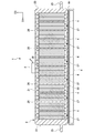
- FIG. 3 is a schematic side view showing only the cell storage body provided in the power storage module shown in FIG.
- FIG. 4 is a schematic perspective view for explaining how the power storage cell and the pressing member are housed in the cell storage space of the power storage module shown in FIG.
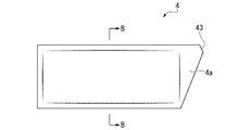
- FIG. 5A is a schematic perspective view showing an example of the pressing member.
- FIG. 5B is a schematic cross-sectional view of FIG. 5A cut along line BB.
- the power storage module 1 shown in the present embodiment includes a cell storage body 2, a cell storage space 27 arranged in the cell storage body 2, a power storage cell 3 housed in the cell storage space 27, and a cell together with the power storage cell 3. It is provided with a pressing member 4 stored in the storage space 27.
- the D1 direction indicates the length direction of the cell accommodating body 2.
- the D2 direction indicates the width direction of the cell storage body 2.
- the D3 direction indicates the height direction of the cell storage body 2.
- the direction indicated by the D3 direction is upward along the direction of gravity.
- the cell storage body 2 has a square tubular shape.
- the cell storage body 2 is arranged at both ends of the top plate 21 and the bottom plate 22 having a rectangular shape long in the D1 direction and the top plate 21 and the bottom plate 22 in the D1 direction, and the side plates 23 and 23 connecting the top plate 21 and the bottom plate 22.
- the top plate 21 and the bottom plate 22 have rectangular openings 24, 24 that open on both end faces in the D2 direction.
- the side plate 23 integrally has a plate-shaped flange portion 25 projecting over the entire length in the width direction along the D1 direction.
- the flange portion 25 is arranged in parallel with the top plate 21 and the bottom plate 22.
- a plurality of (five in this embodiment) partition plates 26 are provided inside the cell storage body 2.
- the partition plates 26 are arranged at equal intervals between the side plates 23 and 23.
- each partition plate 26 is integrally provided over the inner wall surface 21a of the top plate 21 and the inner wall surface 22a of the bottom plate 22.
- the wall surfaces 26a of all partition plates 26 are parallel to each other.
- the wall surface 26a of the partition plate 26 and the inner wall surface 23a of the side plate 23 are parallel to each other.
- the cell storage body 2 of the present embodiment has six cell storage spaces 27 separated by five partition plates 26.
- the six cell storage spaces 27 are arranged linearly along the arrangement direction (D1 direction) of the wall surface 26a of the partition plate 26 and the wall surface 23a of the side plate 23.
- the partition plate 26 extends over the entire length of the cell storage body 2 in the D2 direction. Therefore, the openings 24, 24 that open on both end surfaces of the cell storage body 2 in the D2 direction are the extending directions of the parallel wall surfaces (the wall surface 26a of the partition plate 26 and the wall surface 23a of the side plate 23) of each cell storage space 27. It is also an opening that opens to each.
- the top plate 21, the bottom plate 22, the side plate 23, the flange portion 25, and the partition plate 26 are all preferably formed of a metal material having good heat transfer properties such as aluminum and an aluminum alloy. Since the cell accommodating body 2 has the same shape along the D2 direction, it can be an integrally molded product that is impact-molded or extruded along the D2 direction. Therefore, the cell accommodating body 2 has good strength and heat transfer performance. Further, when the cell storage body 2 is an integrally molded product, it is not necessary to assemble the separately formed parts, so that the number of parts of the cell storage body 2 can be reduced and the cost can be reduced.
- the power storage cell 3 houses a battery element (not shown) having a positive electrode plate and a negative electrode plate inside. As shown in FIG. 4, the storage cell 3 is flat in the D1 direction.
- the storage cell 3 has a horizontally long rectangular shape having a height slightly lower than the height of the cell storage space 27 and a width slightly wider than the width of the cell storage space 27 (width in the D2 direction).
- the storage cell 3 a conventionally known one can be used.
- the power storage cell 3 for example, a cell having a laminated pack shape in which a battery element is enclosed in an exterior body made of a laminate film, a battery element housed in a metal exterior body, or the like can be used.
- the laminate film it is preferable to use a metal foil composite laminate film in which a metal foil and a resin film are adhered to each other.
- the metal foil composite laminated film a known one can be used.
- the metal foil one made of a metal such as aluminum, aluminum alloy, stainless steel, and / or nickel alloy can be used.
- the resin film one made of a resin such as polyethylene, ethylene vinyl acetate, and / or polyethylene terephthalate can be used.
- a battery element such as a lithium ion secondary battery in which the electrolytic solution is housed in the exterior body may be used, or a battery element composed of an all-solid-state battery having no electrolytic solution is housed in the outer body. You may use what was done.
- a cell having a laminate pack shape is used as the power storage cell 3, as shown in FIG. 4, a cell having a laminate pack shape is used. As shown in FIG. 4, a positive electrode terminal 3a electrically connected to the positive electrode plate of the battery element is projected from one end of the power storage cell 3 in the width direction (D2 direction). Further, at the other end of the power storage cell 3 in the width direction (D2 direction), a negative electrode terminal 3b electrically connected to the negative electrode plate of the battery element is projected.
- the power storage cell 3 is arranged so that the positive electrode terminal 3a and the negative electrode terminal 3b are oriented sideways (direction along the D2 direction). By inserting the storage cells 3 through the opening 24, four storage cells 3 are stored in one cell storage space 27 (see FIG. 4). Therefore, a total of 24 power storage cells 3 are distributed and stored in the six cell storage spaces 27 in the cell storage body 2.
- the positive electrode terminal 3a of the power storage cell 3 in the cell storage space 27 is arranged in one of the openings 24 and 24 of each cell storage space 27. Further, the negative electrode terminal 3b of the storage cell 3 is arranged in any one of the openings 24 and 24 of each cell storage space 27 (see FIG. 4).
- the positive electrode terminal 3a and the negative electrode terminal 3b of each storage cell 3 are exposed from the opening 24 and extend outward in the width direction (D2 direction) of the storage cell 3.
- the positive electrode terminal 3a and the negative electrode terminal 3b of each storage cell 3 are arranged apart from each other, the current distribution of the storage cell 3 is made uniform, and the performance deterioration of the storage cell 3 is suppressed.
- the positive electrode terminals 3a and the negative electrode terminals 3b of the adjacent storage cells 3 and 3 are arranged so as to be opposite to each other. That is, the positive electrode terminal 3a of the power storage cell 3 and the positive electrode terminal 3b of the power storage cell 3 adjacent thereto are adjacent to each other. Therefore, the positive electrode terminals 3a and the negative electrode terminals 3b protruding from the opening 24 of each cell storage space 27 are alternately arranged along the D1 direction of the cell storage body 2 (see FIG. 4).
- the positive electrode terminals 3a and the negative electrode terminals 3b of the adjacent storage cells 3 and 3 are electrically connected by a bus bar (not shown). Further, the positive electrode terminals 3a and the negative electrode terminals 3b of the storage cells 3 and 3 may be electrically connected to an external device by a harness (not shown). In the present embodiment, all the storage cells 3 in the cell storage body 2 are preferably connected in series by a bus bar. However, by aligning the directions of the positive electrode terminals 3a and the negative electrode terminals 3b of the power storage cells 3, all the power storage cells 3 in the cell housing 2 may be connected in parallel.
- the pressing member 4 has a deformable member 40 made of an elastic body or an expandable structure, and a storage bag 41 in which the deformable member 40 is housed.
- the storage bag 41 is deformed by changing the shape of the deformable member 40.
- the storage bag 41 can be sealed by closing the storage bag opening 43 provided at the edge 4a of the pressing member 4. When closing the storage bag opening 43, the timing can be arbitrarily selected.
- the pressing member 4 is formed in the shape of a rectangular or substantially rectangular sheet like the storage cell 3. As shown in FIG. 4, the pressing member 4 has a height slightly lower than the height of the cell storage space 27 and a horizontally long width (width in the D2 direction) slightly wider than the width of the cell storage space 27. It has a rectangular shape.
- each pressing member 4 is stored in each cell storage space 27.
- the pressing member 4 is housed in each cell storage space 27 in a state of being laminated with the power storage cell 3, and the wall surface of the cell storage space 27 (the wall surface 26a of the partition plate 26 and the wall surface 23a of the side plate 23) via the power storage cell 3 ) And facing each other.
- the pressing member 4 is sandwiched between the two central storage cells 3 and 3 so as to partition the four storage cells 3 stored in each cell storage space 27 into two. ..
- the edge portion 4a of the pressing member 4 is exposed from any one of the openings 24 and 24 of each cell storage space 27.
- FIG. 5A of the edge portions 4a on the edge of the pressing member 4, the edge portion 4a on one side in the width direction (D2 direction) of the storage cell 3 is one of the edge portions 4a in the width direction of the cell storage space 27.
- the sides (upper side in FIGS. 1 and 5A) extend outward, and one side of the cell storage space 27 in the height direction is inclined with respect to the height direction of the cell storage space 27. ..
- the edge portion 4a has a substantially triangular shape.
- the edge portion 4a exposed from the opening 24 has a storage bag opening 43 formed by chamfering the vicinity of the substantially triangular apex of the edge portion 4a. It is provided. As shown in FIG. 1, the storage bag opening 43 is arranged at a position that does not overlap with the positive electrode terminal 3a or the negative electrode terminal 3b when viewed from the thickness direction of the power storage cell 3. Therefore, the power storage module 1 of the present embodiment has a positive electrode terminal 3a or a negative electrode terminal when the storage bag 41 is opened by cutting the edge portion 4a exposed from the opening 24 of the cell storage space 27 in the restoration step described later. 3b is preferable because it has a structure that does not easily get in the way.
- the edge portion 4a of the pressing member 4 exposed from the opening 24 has a substantially triangular shape
- the shape of the edge portion 4a is not limited to a substantially triangular shape. Absent.
- the shape of the edge 4a of the pressing member 4 exposed from the opening 24 may be, for example, a shape in which both sides of the cell storage space 27 in the width direction are longer than the width of the cell storage space 27.
- the shape of the storage bag opening 43 is not limited to the examples shown in FIGS. 1 and 5A.
- the shape may be, for example, a hole or a notch having an arbitrary planar shape penetrating the edge 4a of the pressing member 4.
- the storage bag opening 43 is the storage cell. 3 is preferably arranged at a position where it does not overlap with the positive electrode terminal 3a or the negative electrode terminal 3b when viewed from the thickness direction of 3.
- the storage bag 41 is preferably formed of a metal foil composite laminated film or a resin film in which a metal foil and a resin film are adhered to each other.
- a metal foil composite laminated film a known one can be used.
- the metal foil one made of a metal such as aluminum, aluminum alloy, stainless steel, and / or nickel alloy can be used.
- the resin film one made of a resin such as polyethylene, ethylene vinyl acetate, and / or polyethylene terephthalate can be used.
- the pressing member 4 can be used as an insulator.
- the power storage cell 3 uses an exterior body made of a metal cell can
- the pressing member 4 can be used as an insulator between the power storage cells 3 and 3 adjacent to each other with the pressing member 4 interposed therebetween, which is preferable. ..
- the elastic body used for the deformable member 40 of the pressing member 4 for example, a foam made of rubber, resin, or the like can be used.
- a foam made of rubber, resin, or the like
- the degree of absorption of the pressing force against the storage cell 3 and the expansion force of the storage cell 3 can be easily adjusted by appropriately setting the foaming ratio of the foam.
- the power storage module 1 can be further reduced in weight and cost.
- the swellable structure used for the deformable member 40 for example, a structure that swells by impregnating with a liquid can be used.
- a structure that swells by impregnating with a liquid it is preferable to use a resin fiber aggregate.
- the resin fiber aggregate include a laminate of non-woven fabrics made of polyolefin resin fibers, phenol resin fibers, and the like.
- the polyolefin-based resin fiber polypropylene fiber or the like can be used.
- the deformable member 40 has excellent heat resistance, which is preferable.
- a structure that swells by impregnating with a liquid and a liquid can be preferably combined and used.
- the pressing force and the power storage against the storage cell 3 are appropriately adjusted by appropriately adjusting the density, type, diameter, length, shape, etc. of the fibers forming the resin fiber aggregate.
- the degree of absorption of the expansion force of the cell 3 can be easily adjusted.
- the deformable member 40 is a resin fiber aggregate, it is possible to further reduce the weight and cost of the power storage module 1 as in the case of the foam.
- the fluid contained in the storage bag 41 may be sealed in the storage bag 41 by heat-welding and closing the storage bag opening 43.
- a gas may be used or a liquid may be used.
- a resin fiber aggregate which is a structure that swells by impregnating with a liquid, is used as the deformable member 40, it is preferable to use a liquid as the fluid.
- the fluid enclosed in the storage bag 41 is a gas, it is preferable to use air. Gases such as carbon dioxide and nitrogen may be used in place of or in combination with air.
- the fluid enclosed in the storage bag 41 is a liquid, it is preferable to use water. Instead of or with water, ethylene glycol or a liquid such as an organic solvent, an insulating oil, or a fluorine-based inert liquid may be used.
- each pressing member 4 has a wall surface 26a or a side plate 23 of the partition plate 26 with respect to the four storage cells 3 housed in the same cell storage space 27 as each pressing member 4.
- a pressing force is applied to the wall surface 23a. That is, each pressing member 4 directs two storage cells 3 arranged on both sides of the pressing member 4 in the same cell storage space 27 toward the wall surface 26a of the partition plate 26 or the wall surface 23a of the side plate 23. It is pressed with a predetermined pressing force. With this configuration, four storage cells 3 in each cell storage space 27 are held in the power storage module 1 without rattling in each cell storage space 27.
- the two parallel wall surfaces 26a and 26a or the wall surface 26a and the wall surface 23a separating the cell storage space 27 can be effectively used as heat transfer surfaces, respectively. That is, the storage cell 3 is pressed against the wall surface 26a of the partition plate 26 or the wall surface 23a of the side plate 23 by the pressing member 4. As a result, the contact thermal resistance between the storage cell 3 and the wall surfaces 23a and 26a is reduced, and heat exchange between the storage cell 3 and the wall surfaces 23a and 26a is promoted.
- the deformable member 40 of the pressing member 4 is compressed by the expansion force of the storage cell 3 when the storage cell 3 in the cell storage space 27 expands by charging / discharging.
- the pressing member 4 reduces the load on the wall surface 26a of each partition plate 26 and the wall surface 23a of the side plate 23 when the power storage cell 3 expands, and the power storage cell 3 expands to the cell storage body 2. Reduce the load.
- the deformable member 40 of the pressing member 4 is compressed, and the pressing load on the cell accommodating body 2 due to the expansion of the storage cell 3 is canceled. Therefore, the strength of the wall surface 26a of the partition plate 26 and the wall surface 23a of the side plate 23 can be set small, and the weight and cost of the power storage module 1 can be reduced.
- the method of manufacturing the power storage module of the present embodiment will be described in detail with reference to preferred examples.
- the cell accommodating body 2 which is an integrally molded product is manufactured by impact molding or extrusion molding.
- the storage cell 3 is manufactured by a conventionally known method.
- two horizontally long rectangular metal leaf composite laminated films corresponding to the shape of the storage bag 41 of the pressing member 4 are prepared, and the two long sides and one short side are heat-welded and joined to one.
- a storage bag 41 having an open short side is formed. Further, both ends of the strip-shaped metal leaf composite laminated film are heat-welded to form a tubular shape, and one end of the tubular metal leaf composite laminated film is heat-welded and joined to open one short side.
- the storage bag 41 may be formed.
- the deformable member 40 made of an elastic body or an expandable structure is housed in the storage bag 41. Subsequently, the deformable member 40 is compressed by reducing the pressure inside the storage bag 41. After that, the openings of the storage bag 41 are heat-sealed and joined to seal the storage bag 41 and form a predetermined edge 4a shape.
- the shape of one edge 4a in the width direction (D2 direction) of the power storage cell 3 of the pressing member 4 is such that one side in the width direction of the cell storage space 27 extends outward and the cell.
- One side of the storage space 27 in the height direction is inclined with respect to the height direction of the cell storage space 27, and has a substantially triangular shape (see FIG. 4).
- the power storage cell 3 and the pressing member 4 are laminated and stored in the cell storage space 27 having parallel wall surfaces arranged in the cell storage body 2 (lamination step). ..
- the two storage cells 3, the pressing member 4, and the two storage cells 3 are stacked in this order and inserted into each cell storage space 27 through the opening 24 for storage.
- the deformable member 40 of the pressing member 4 when the pressing member 4 is stacked with the power storage cell 3 and stored in the cell storage space 27, the deformable member 40 of the pressing member 4 is in a compressed state. Therefore, the thickness of the laminated body including the pressing member 4 and the storage cell 3 is smaller than the width of the cell storage space 27. As a result, when manufacturing the power storage module 1 of the present embodiment, the laminate composed of the pressing member 4 and the power storage cell 3 can be easily inserted into the cell storage space 27 and can be efficiently assembled.
- the edge portion 4a exposed from the opening 24 of the cell storage space 27 is cut to open the storage bag 41 to form the storage bag opening 43 (see FIG. 1).
- air which is a fluid, flows into the storage bag 41 from the storage bag opening 43.
- the deformable member 40 is restored from the compressed state in the storage bag 41 and expanded, and the volume of the deformable member 40 increases.
- the pressing member 4 applies a pressing force to the wall surface (the wall surface 26a of the partition plate 26 and the wall surface 23a of the side plate 23) to the power storage cell 3 (restoration step).
- the method of cutting the edge portion 4a to open the storage bag 41 can be arbitrarily selected.
- a method of removing a part of the edge portion 4a by shearing or making a cut in a part of the edge portion 4a, or a method of punching the edge portion 4a For example, a method of removing a part of the edge portion 4a by shearing or making a cut in a part of the edge portion 4a, or a method of punching the edge portion 4a. Conventionally known methods such as a method of making a hole in a part can be used.
- the pressing member 4 having the compressed deformable member 40 and the storage cell 3 are laminated, and this laminated body is stored in the cell storage space 27.
- the storage bag 41 is opened, and the pressing member 4 is expanded in the thickness direction (D1 direction) inside the cell storage space 27.
- the pressing member 4 presses the power storage cell 3 against the wall surface 26a of the partition plate 26 or the wall surface 23a of the side plate 23, and the power storage cell 3 in the cell storage space 37 is securely held without rattling.
- the pressing member 4 is not held by adhering the power storage cell 3 with an adhesive. Therefore, the power storage module 1 of the present embodiment is easy to disassemble and has excellent recyclability.
- the storage bag opening 43 formed by opening the storage bag 41 may be closed after air has flowed into the storage bag 41.
- the timing for closing the storage bag opening 43 may be adjusted as appropriate after the storage bag 41 is opened to form the storage bag opening 43.
- the storage bag opening 43 can be closed by, for example, a method of heat welding and joining.
- the thickness of the pressing member 4 in the cell storage space 27 is adjusted according to the amount of air flowing into the storage bag 41 to adjust the storage cell.
- the magnitude of the force that presses 3 against the wall surfaces 23a and 26a can be adjusted.
- the restoration step when a resin fiber aggregate which is a structure that swells by impregnating a liquid is used as the deformable member 40 in the pressing member forming step described above, in the restoration step. It is preferable to close the storage bag opening 43 after injecting a liquid as a fluid into the storage bag 41 from the storage bag opening 43 formed by opening the storage bag 41.
- the resin fiber aggregate which is the deformable member 40
- the resin fiber aggregate is restored from the compressed state in the storage bag 41 by opening the storage bag 41 and expands, and further expands by impregnating the liquid to increase the volume. Increase.
- the pressing member 4 applies a pressing force to the wall surface of the power storage cell 3.
- the thickness of the pressing member 4 in the cell storage space 27 can be adjusted according to the amount of the liquid flowing into the storage bag 41, and the magnitude of the force for pressing the storage cell 3 against the wall surfaces 23a and 26a can be adjusted.
- the pressing force of the pressing member 4 against the wall surface against the storage cell 3 is less affected by the atmospheric pressure fluctuation and becomes stable. preferable.
- the power storage module 1 of the present embodiment is arranged to face the wall surface of the cell storage space 27 (the wall surface 26a of the partition plate 26 and the wall surface 23a of the side plate 23) via the power storage cell 3, and is pressed against the wall surface against the power storage cell 3.
- a sheet-shaped pressing member 4 for applying a force is provided. Therefore, in the power storage module 1 of the present embodiment, the plurality of power storage cells 3 are held without rattling due to the effect of the pressing member 4, and the power storage cells 3 move when acceleration is input from the stacking direction of the power storage cells 3. Is suppressed. Therefore, the power storage module 1 of the present embodiment has good reliability of electrical connection.
- the deformable member 40 is compressed and sealed by depressurizing the inside of the storage bag 41, and in the stacking step, power is stored in the cell storage space 27.
- the cell 3 and the pressing member 4 are stacked and stored, and in the restoration step, the storage bag 41 is opened and the fluid flows into the storage bag 41 to restore the deformable member 40 from the compressed state. Therefore, the power storage module 1 of the present embodiment is obtained in which the plurality of power storage cells 3 are held without rattling and the movement of the power storage cells 3 at the time of inputting acceleration from the stacking direction of the power storage cells 3 is suppressed. ..
- FIG. 6 is a diagram illustrating the effect of the power storage module according to the present invention.
- a collision load F is input to the power storage module 1 mounted on a vehicle (not shown) along the arrangement direction (D1 direction) of the power storage cells 3, the collision load F is in the cell storage body 2. It acts to move all the storage cells 3 of the above along the input direction (D1 direction) of the collision load F.
- the cell storage body is not divided by a partition plate, and one pressing member is arranged in the center so as to divide the 24 power storage cells into two by 12 pieces. ..
- the movement amount of the power storage cell arranged on the input side of the collision load F (the right end side in the case of FIG. 6) is the largest, and the movement amount is the largest, and the side opposite to the input side of the collision load F (the left end side in the case of FIG. 6). ) Is greatly compressed under the load of the other 23 storage cells.
- the maximum movement amount of the storage cell (arranged on the input side of the collision load F).
- the power storage module 1 of the present embodiment at least one of a heat sink, a temperature control device, and a temperature measurement device is provided on the outer surface (outer surface of the top plate 21, the bottom plate 22 and the side plate 23) of the cell storage body 2.
- the cell accommodating body 2 in the present embodiment is an integrally molded product made of a metal material, it has good heat transfer performance.
- the temperatures of the wall surfaces 23a and 26a in the cell storage space 27 and the temperature of the outer surface of the cell storage body 2 are made uniform. Therefore, in the present embodiment, it is easy to mount the heat sink, the temperature control device, and the temperature measurement device on the outer surface of the cell storage body 2, and it is possible to easily improve the assembling property and reduce the assembling cost. is there.
- FIG. 7 is a schematic cross-sectional view showing a state in which a temperature control device and a temperature measurement device are attached to the power storage module shown in FIG.
- the top plate 21 of the cell storage body 2 is provided with a temperature sensor 5 as a temperature measuring device.
- the temperatures of the wall surfaces 23a and 26a in the cell storage space 27 and the outer surface of the cell storage body 2 are made uniform, so that one temperature sensor 5 can be used in each cell storage space 27.
- the temperature of the storage cell 3 can be indirectly measured.
- the bottom plate 22 of the cell storage body 2 is provided with a water jacket 6 as a temperature control device.
- the water jacket 6 is made of a hollow member made of a metal such as aluminum, and has a passage through which a refrigerant such as water or cooling air flows. As shown in FIG. 7, it is preferable that the heat transfer sheet 61 is arranged between the water jacket 6 and the bottom plate 22. In the electricity storage module 1 of the present embodiment, the electricity storage cell 3 in each cell storage space 27 can be efficiently cooled by the water jacket 6 via the heat transfer sheet 61 and the bottom plate 22.
- FIG. 8 is a schematic perspective view for explaining how the power storage cell and the pressing member are housed in the cell storage space of the power storage module according to another embodiment of the present invention.
- the same members as those of the power storage module 1 of the first embodiment are designated by the same reference numerals, and the description thereof will be omitted.
- the positive electrode terminal 3a and the negative electrode terminal 3b of the power storage cell 3 have the opening 24 of the cell storage space 27. It is located in only one of the 24. Then, as shown in FIG. 8, the edge portion 46 of the pressing member 4 is exposed from the opening 24 of the cell storage space 27 on the side where the positive electrode terminal 3a and the negative electrode terminal 3b of the storage cell 3 are not arranged.
- the edge portions 4a on the edge of the pressing member 4 one edge portion 4a (46) in the width direction (D2 direction) of the power storage cell 3 is both in the width direction of the cell storage space 27, as shown in FIG. The length of the side is made longer than the width of the cell storage space 27.
- the pressing member 4 is a rectangle long in the D2 direction.
- the edge 46 exposed from the opening 24 is provided with a storage bag opening along the entire height direction of the cell storage space 27 (not shown in FIG. 8). That is, in the power storage module 10 of the second embodiment, the storage bag opening is provided in the edge portion 46 exposed from the opening 24 on the side where the positive electrode terminal 3a and the negative electrode terminal 3b are not arranged. Therefore, in the restoration step described later, the power storage module 10 of the second embodiment cuts the edge 46 exposed from the opening 24 of the cell storage space 27 to form the storage bag opening and opens the storage bag 41. At that time, the positive electrode terminal 3a or the negative electrode terminal 3b does not get in the way, which is preferable.
- the cell accommodating body 2 and the storage cell 3 are manufactured in the same manner as in the manufacturing method of the power storage module 1 of the first embodiment.
- a storage bag 41 having one short side opened is formed, and the deformable member 40 is stored in the storage bag 41.
- the deformable member 40 is compressed, the storage bag 41 is sealed, and a predetermined edge portion 4a shape is formed.
- one edge 4a (46) of the power storage cell 3 of the pressing member 4 in the width direction (D2 direction) is a cell.
- the length of both sides in the width direction of the storage space 27 is made sufficiently longer than the width of the cell storage space 27 (width in the X direction).
- the laminating step and the restoring step are performed in this order in the same manner as in the manufacturing method of the power storage module 1 of the first embodiment. Then, in the second embodiment as well, as in the first embodiment, the storage bag opening formed by opening the storage bag 41 may be closed after the fluid has flowed into the storage bag 41.
- the power storage module 10 of the present embodiment is arranged to face the wall surface of the cell storage space 27 (the wall surface 26a of the partition plate 26 and the wall surface 23a of the side plate 23) via the power storage cell 3.
- a sheet-shaped pressing member 4 is provided, which applies a pressing force to the wall surface of the storage cell 3. Therefore, also in the power storage module 10 of the present embodiment, the plurality of power storage cells 3 are held without rattling, and the movement of the power storage cells 3 at the time of acceleration input from the stacking direction of the power storage cells 3 is suppressed. Therefore, the power storage module 1 of the present embodiment has good reliability of electrical connection.
- the present invention can make various design changes without departing from the gist thereof.
- the case where six cell storage spaces are arranged linearly in the parallel wall surface arrangement direction in the cell storage body 2 has been described as an example, but the cells are arranged in the cell storage body.
- the number of cell storage spaces to be stored is not limited to 6, but may be 1 to 5, or may be 7 or more.
Abstract
A power storage module (1) includes: a cell storage body (2); cell storage spaces (27) that are disposed in the cell storage body (2) and that have parallel wall surfaces; power storage cells (3) that are stored in the cell storage spaces (27); and sheet-like pressing members (4) that are disposed facing the wall surfaces of the cell storage space (27) via the power storage cell (3), and that apply a force for pressing the power storage cells (3) against the wall surfaces. Each pressing member (4) includes a deformable member comprising an elastic body or an expandable structure, and a storage bag in which the deformable member is stored. The storage bag can be sealed by closing the storage bag opening, and deforms due to shape deformation of the deformable member.
Description
本発明は、蓄電モジュール及び蓄電モジュールの製造方法に関する。
本願は、2019年7月10日に、日本に出願された特願2019-128329号に基づき優先権を主張し、その内容をここに援用する。 The present invention relates to a power storage module and a method for manufacturing the power storage module.
The present application claims priority based on Japanese Patent Application No. 2019-128329 filed in Japan on July 10, 2019, the contents of which are incorporated herein by reference.
蓄電モジュールは、ハイブリッドカー、電気自動車などに搭載されている。蓄電モジュールは、複数の蓄電セルが積層されて構成されている。蓄電セルは、正極および負極からなる電池要素を含む。蓄電セルとしては、金属製のセル缶の内部に電池要素が収容されたもの、樹脂製のラミネートフィルム内に電池要素が封入されたものがある。
The power storage module is installed in hybrid cars, electric vehicles, etc. The power storage module is configured by stacking a plurality of power storage cells. The storage cell includes a battery element consisting of a positive electrode and a negative electrode. As the storage cell, there are one in which the battery element is housed inside a metal cell can, and one in which the battery element is enclosed in a resin laminated film.
例えば、特許文献1には、電池要素の少なくとも一方の面に電池要素の積層方向に弾発力を付与する弾性体が配置され、電池要素と弾性体とはラミネートフィルムで真空包装されているラミネート二次電池が、並列接続、直列接続または直並列接続されてなる組電池モジュールが記載されている。
For example, in Patent Document 1, an elastic body that imparts elasticity in the laminating direction of the battery element is arranged on at least one surface of the battery element, and the battery element and the elastic body are vacuum-packed with a laminating film. An assembled battery module in which a secondary battery is connected in parallel, in series, or in series and parallel is described.
車両搭載される蓄電モジュールでは、走行時等の振動を受けて蓄電セルがガタつくことにより、蓄電セル同士または蓄電セルと外部との電気的接続の信頼性が損なわれるおそれがある。
また、蓄電モジュールに対して、蓄電セルの積層方向に衝突荷重などによる加速度が入力されると、全ての蓄電セルが加速度の入力方向に沿って移動する。このときの各蓄電セルの移動量は、加速度の入力側に配置される蓄電セルほど大きい。このため、蓄電モジュールにおける蓄電セルの電極端子と、バスバーおよび/またはハーネスの接続部位との位置関係が、相対的に大きく変動する。その結果、蓄電セルの電極端子との接続部位に大きな負荷が掛かり、蓄電モジュールにおける電気的接続の信頼性が損なわれる場合があった。 In a power storage module mounted on a vehicle, the power storage cells may rattle due to vibration during traveling or the like, which may impair the reliability of the electrical connection between the power storage cells or between the power storage cells and the outside.
Further, when acceleration due to a collision load or the like is input to the power storage module in the stacking direction of the power storage cells, all the power storage cells move along the input direction of the acceleration. The amount of movement of each storage cell at this time is larger as the storage cell is arranged on the input side of the acceleration. Therefore, the positional relationship between the electrode terminal of the storage cell in the power storage module and the connection portion of the bus bar and / or harness fluctuates relatively greatly. As a result, a large load is applied to the connection portion of the power storage cell with the electrode terminal, and the reliability of the electrical connection in the power storage module may be impaired.
本発明は、上記事情を鑑みてなされたものであり、複数の蓄電セルがガタつくことなく保持されるとともに、蓄電セルの積層方向からの加速度入力時における蓄電セルの移動が抑制される、電気的接続の信頼性が良好な蓄電モジュールおよび蓄電モジュールの製造方法を提供することを目的とする。
The present invention has been made in view of the above circumstances, and a plurality of storage cells are held without rattling, and the movement of the storage cells at the time of acceleration input from the stacking direction of the storage cells is suppressed. It is an object of the present invention to provide a power storage module and a method for manufacturing a power storage module having good reliable connection.
上記目的を達成するために、本発明は以下の手段を提供する。
(1) セル収納体と、
前記セル収納体内に配置され、平行な壁面を有するセル収納空間と、
前記セル収納空間内に収納された蓄電セルと、
前記蓄電セルを介して前記セル収納空間の壁面と対向配置され、前記蓄電セルに対して前記壁面への押し付け力を付与するシート状の押し付け部材とが備えられ、
前記押し付け部材は、弾性体または膨張性を有する構造体からなる変形可能部材と、前記変形可能部材が収容された収容袋とを有し、
前記収容袋は、収容袋開口部を閉じることにより密閉可能であって前記変形可能部材の形状変化によって変形する、蓄電モジュール。 In order to achieve the above object, the present invention provides the following means.
(1) Cell storage body and
A cell storage space arranged inside the cell storage body and having a parallel wall surface,
The storage cell stored in the cell storage space and
A sheet-like pressing member that is arranged to face the wall surface of the cell storage space via the storage cell and exerts a pressing force on the wall surface with respect to the storage cell is provided.
The pressing member has a deformable member made of an elastic body or an inflatable structure, and a storage bag in which the deformable member is housed.
The storage bag is a power storage module that can be sealed by closing the storage bag opening and is deformed by changing the shape of the deformable member.
(2) 前記押し付け部材が、厚さ方向に膨張することにより前記蓄電セルを前記壁面に押し付けるものである、(1)に記載の蓄電モジュール。
(3) 前記押し付け部材は、2つの前記蓄電セルの間に挟まれている、(1)または(2)に記載の蓄電モジュール。 (2) The power storage module according to (1), wherein the pressing member pushes the power storage cell against the wall surface by expanding in the thickness direction.
(3) The power storage module according to (1) or (2), wherein the pressing member is sandwiched between two power storage cells.
(4) 前記収容袋内に流体が封入されている、(1)~(3)のいずれかに記載の蓄電モジュール。
(5) 前記変形可能部材が発泡体である、(1)~(4)のいずれかに記載の蓄電モジュール。
(6) 前記変形可能部材が樹脂繊維集合体である、(1)~(4)のいずれかに記載の蓄電モジュール。 (4) The power storage module according to any one of (1) to (3), wherein a fluid is sealed in the storage bag.
(5) The power storage module according to any one of (1) to (4), wherein the deformable member is a foam.
(6) The power storage module according to any one of (1) to (4), wherein the deformable member is an aggregate of resin fibers.
(7) 前記セル収納空間が、前記平行な壁面の延在方向にそれぞれ開口する開口部を有し、
前記蓄電セルの正極端子は、前記開口部のうちの一方に配置され、前記蓄電セルの負極端子は、前記開口部のうちの他方に配置され、
前記開口部のうちの一方または他方から露出した前記押し付け部材の縁部に前記収容袋開口部が設けられ、前記収容袋開口部が、前記蓄電セルの厚さ方向から見て前記正極端子または前記負極端子と重ならない位置に配置されている、(1)~(6)のいずれかに記載の蓄電モジュール。 (7) The cell storage space has an opening that opens in the extending direction of the parallel wall surface.
The positive electrode terminal of the storage cell is arranged in one of the openings, and the negative electrode terminal of the storage cell is arranged in the other of the openings.
The storage bag opening is provided at the edge of the pressing member exposed from one or the other of the openings, and the storage bag opening is the positive electrode terminal or the positive electrode terminal when viewed from the thickness direction of the power storage cell. The power storage module according to any one of (1) to (6), which is arranged at a position where it does not overlap with the negative electrode terminal.
(8) 前記セル収納空間が、前記平行な壁面の延在方向にそれぞれ開口する開口部を有し、
前記蓄電セルの正極端子および負極端子が、前記開口部のうちの一方に配置され、
前記開口部のうちの他方から露出した前記押し付け部材の縁部に収容袋開口部が設けられている、(1)~(6)のいずれかに記載の蓄電モジュール。 (8) The cell storage space has an opening that opens in the extending direction of the parallel wall surface.
The positive electrode terminal and the negative electrode terminal of the power storage cell are arranged in one of the openings.
The power storage module according to any one of (1) to (6), wherein a storage bag opening is provided at an edge of the pressing member exposed from the other of the openings.
(9) 前記セル収納体の内部に、複数のセル収納空間が、前記平行な壁面の並び方向に直線状に配列されている、(1)~(8)のいずれかに記載の蓄電モジュール。
(10) 前記セル収納体は、金属材をインパクト成形または押出し成形した一体成形品である、(1)~(9)のいずれかに記載の蓄電モジュール。 (9) The power storage module according to any one of (1) to (8), wherein a plurality of cell storage spaces are linearly arranged in the arrangement direction of the parallel wall surfaces inside the cell storage body.
(10) The power storage module according to any one of (1) to (9), wherein the cell housing is an integrally molded product obtained by impact molding or extrusion molding of a metal material.
(11) 弾性体または膨張性を有する構造体からなる変形可能部材を収容袋に収容し、前記収容袋内を減圧することにより前記変形可能部材を圧縮した後、前記収容袋を密閉することによりシート状の押し付け部材を形成する押し付け部材形成工程と、
セル収納体内に配置された平行な壁面を有するセル収納空間内に、蓄電セルと、前記押し付け部材とを積層して収納する積層工程と、
前記収容袋を開口して収容袋開口部を形成し、前記収容袋開口部から前記収容袋内に流体を流入して前記変形可能部材を圧縮状態から復元することにより、前記押し付け部材に前記蓄電セルに対して前記壁面への押し付け力を付与する復元工程とを有する、蓄電モジュールの製造方法。 (11) A deformable member made of an elastic body or an expandable structure is housed in a storage bag, the deformable member is compressed by reducing the pressure inside the storage bag, and then the storage bag is sealed. A pressing member forming process for forming a sheet-shaped pressing member, and
A laminating step of laminating and storing a power storage cell and the pressing member in a cell storage space having parallel wall surfaces arranged inside the cell storage body.
The storage bag is opened to form a storage bag opening, and a fluid flows into the storage bag from the storage bag opening to restore the deformable member from the compressed state, whereby the storage is stored in the pressing member. A method for manufacturing a power storage module, which comprises a restoration step of applying a pressing force to the wall surface of the cell.
(12) 前記押し付け部材形成工程において、変形可能部材として樹脂繊維集合体を用い、
前記復元工程において、前記流体として液体を流入した後、前記収容袋開口部を閉じる、(11)に記載の蓄電モジュールの製造方法。 (12) In the pressing member forming step, a resin fiber aggregate is used as the deformable member.
The method for manufacturing a power storage module according to (11), wherein in the restoration step, the opening of the storage bag is closed after the liquid has flowed in as the fluid.
本発明によれば、複数の蓄電セルがガタつくことなく保持されるとともに、蓄電セルの積層方向からの加速度入力時における蓄電セルの移動が抑制されることにより、良好な電気的接続の信頼性が得られる蓄電モジュールおよび蓄電モジュールの製造方法を提供できる。
According to the present invention, a plurality of storage cells are held without rattling, and the movement of the storage cells at the time of inputting acceleration from the stacking direction of the storage cells is suppressed, so that the reliability of good electrical connection is good. Can provide a power storage module and a method for manufacturing the power storage module.
以下、本発明の蓄電モジュールおよび蓄電モジュールの製造方法について、図面を参照しながら詳細に説明する。なお、以下の説明で用いる図面は、本発明の特徴をわかりやすくするために便宜上特徴となる部分を拡大して示している場合がある。このため、各構成要素の寸法比率などは、実際とは異なっていることがある。また、以下の説明において例示される材質、寸法等は一例である。したがって、本発明は、以下に示す実施形態のみに限定されるものではなく、本発明の要件を変更しない範囲で適宜変更して実施できる。
Hereinafter, the power storage module of the present invention and the manufacturing method of the power storage module will be described in detail with reference to the drawings. In addition, in the drawing used in the following description, in order to make the feature of the present invention easy to understand, the feature portion may be enlarged and shown for convenience. Therefore, the dimensional ratio of each component may differ from the actual one. Further, the materials, dimensions, etc. exemplified in the following description are examples. Therefore, the present invention is not limited to the embodiments shown below, and can be appropriately modified and implemented without changing the requirements of the present invention.
[第1実施形態]
図1は、本発明の一実施形態に係る蓄電モジュールの好ましい例を示した概略斜視図である。図2は、図1に示す蓄電モジュールをA-A線に沿って切断した概略断面図である。図3は、図1に示す蓄電モジュールに備えられたセル収納体のみを示した概略側面図である。図4は、図1に示す蓄電モジュールのセル収納空間内に蓄電セルと押し付け部材とを収納する様子を説明するための概略斜視図である。図5Aは、押し付け部材の一例を示した概略斜視図である。図5Bは、図5AをB-B線に沿って切断した概略断面図である。 [First Embodiment]
FIG. 1 is a schematic perspective view showing a preferable example of the power storage module according to the embodiment of the present invention. FIG. 2 is a schematic cross-sectional view of the power storage module shown in FIG. 1 cut along the line AA. FIG. 3 is a schematic side view showing only the cell storage body provided in the power storage module shown in FIG. FIG. 4 is a schematic perspective view for explaining how the power storage cell and the pressing member are housed in the cell storage space of the power storage module shown in FIG. FIG. 5A is a schematic perspective view showing an example of the pressing member. FIG. 5B is a schematic cross-sectional view of FIG. 5A cut along line BB.
本実施形態に示す蓄電モジュール1は、セル収納体2と、セル収納体2内に配置されたセル収納空間27と、セル収納空間27内に収納された蓄電セル3と、蓄電セル3と共にセル収納空間27に収納された押し付け部材4とを備えている。
図1~図4、図6~図8中に示す方向において、D1方向は、セル収納体2の長さ方向を示す。D2方向は、セル収納体2の幅方向を示す。D3方向は、セル収納体2の高さ方向を示す。D3方向の示す方向が重力方向に沿う上方である。 Thepower storage module 1 shown in the present embodiment includes a cell storage body 2, a cell storage space 27 arranged in the cell storage body 2, a power storage cell 3 housed in the cell storage space 27, and a cell together with the power storage cell 3. It is provided with a pressing member 4 stored in the storage space 27.
In the directions shown in FIGS. 1 to 4 and 6 to 8, the D1 direction indicates the length direction of the cellaccommodating body 2. The D2 direction indicates the width direction of the cell storage body 2. The D3 direction indicates the height direction of the cell storage body 2. The direction indicated by the D3 direction is upward along the direction of gravity.
図1~図4、図6~図8中に示す方向において、D1方向は、セル収納体2の長さ方向を示す。D2方向は、セル収納体2の幅方向を示す。D3方向は、セル収納体2の高さ方向を示す。D3方向の示す方向が重力方向に沿う上方である。 The
In the directions shown in FIGS. 1 to 4 and 6 to 8, the D1 direction indicates the length direction of the cell
図1に示すように、セル収納体2は、角筒状である。セル収納体2は、D1方向に長い矩形状の天板21および底板22と、天板21および底板22のD1方向の両端に配置され、天板21および底板22を連結する側板23、23と、天板21および底板22のD2方向の両端面に開口する矩形状の開口部24、24とを有する。
側板23は、D1方向に沿って幅方向の全長に亘って張り出した板状のフランジ部25を一体に有している。フランジ部25は、天板21および底板22と平行に配置されている。 As shown in FIG. 1, thecell storage body 2 has a square tubular shape. The cell storage body 2 is arranged at both ends of the top plate 21 and the bottom plate 22 having a rectangular shape long in the D1 direction and the top plate 21 and the bottom plate 22 in the D1 direction, and the side plates 23 and 23 connecting the top plate 21 and the bottom plate 22. , The top plate 21 and the bottom plate 22 have rectangular openings 24, 24 that open on both end faces in the D2 direction.
Theside plate 23 integrally has a plate-shaped flange portion 25 projecting over the entire length in the width direction along the D1 direction. The flange portion 25 is arranged in parallel with the top plate 21 and the bottom plate 22.
側板23は、D1方向に沿って幅方向の全長に亘って張り出した板状のフランジ部25を一体に有している。フランジ部25は、天板21および底板22と平行に配置されている。 As shown in FIG. 1, the
The
図3に示すように、セル収納体2の内部には、複数(本実施形態では5枚)の仕切り板26が設けられている。各仕切り板26は、両側板23、23の間に均等間隔で配置されている。図3に示すように、各仕切り板26は、天板21の内側の壁面21aと、底板22の内側の壁面22aとに亘って一体に設けられている。全ての仕切り板26の壁面26aは、互いに平行である。また、仕切り板26の壁面26aと、側板23の内側の壁面23aとは、互いに平行である。これにより、セル収納体2の内部には、隣り合う2枚の仕切り板26、26の平行な壁面26a、26aとの間、および側板23の壁面23aと仕切り板26の壁面26aとの間に、それぞれ蓄電セル3を収納可能なセル収納空間27が隔成されている。
As shown in FIG. 3, a plurality of (five in this embodiment) partition plates 26 are provided inside the cell storage body 2. The partition plates 26 are arranged at equal intervals between the side plates 23 and 23. As shown in FIG. 3, each partition plate 26 is integrally provided over the inner wall surface 21a of the top plate 21 and the inner wall surface 22a of the bottom plate 22. The wall surfaces 26a of all partition plates 26 are parallel to each other. Further, the wall surface 26a of the partition plate 26 and the inner wall surface 23a of the side plate 23 are parallel to each other. As a result, inside the cell storage body 2, between the parallel wall surfaces 26a and 26a of the two adjacent partition plates 26 and 26, and between the wall surface 23a of the side plate 23 and the wall surface 26a of the partition plate 26. , Cell storage spaces 27 capable of storing the storage cells 3 are separated from each other.
本実施形態のセル収納体2は、図3に示すように、5枚の仕切り板26によって隔成された6つのセル収納空間27を有する。6つのセル収納空間27は、仕切り板26の壁面26aおよび側板23の壁面23aの並び方向(D1方向)に沿って直線状に配列されている。仕切り板26は、セル収納体2のD2方向の全長に亘って延びている。このため、セル収納体2のD2方向の両端面に開口する開口部24、24は、各セル収納空間27の平行な壁面(仕切り板26の壁面26aおよび側板23の壁面23a)の延在方向にそれぞれ開口する開口部でもある。
As shown in FIG. 3, the cell storage body 2 of the present embodiment has six cell storage spaces 27 separated by five partition plates 26. The six cell storage spaces 27 are arranged linearly along the arrangement direction (D1 direction) of the wall surface 26a of the partition plate 26 and the wall surface 23a of the side plate 23. The partition plate 26 extends over the entire length of the cell storage body 2 in the D2 direction. Therefore, the openings 24, 24 that open on both end surfaces of the cell storage body 2 in the D2 direction are the extending directions of the parallel wall surfaces (the wall surface 26a of the partition plate 26 and the wall surface 23a of the side plate 23) of each cell storage space 27. It is also an opening that opens to each.
セル収納体2は、天板21、底板22、側板23、フランジ部25および仕切り板26の全てが、アルミニウム、アルミニウム合金などの伝熱性の良好な金属材により好ましく形成されている。セル収納体2は、D2方向に沿って同一形状であるため、このD2方向に沿ってインパクト成形または押出し成形された一体成形品とすることができる。従って、セル収納体2は、強度および伝熱性能の良好なものとなる。また、セル収納体2が一体成形品である場合、別々に形成した各部品を組み付けする必要がないため、セル収納体2の部品点数を削減でき、低コスト化が可能である。
In the cell storage body 2, the top plate 21, the bottom plate 22, the side plate 23, the flange portion 25, and the partition plate 26 are all preferably formed of a metal material having good heat transfer properties such as aluminum and an aluminum alloy. Since the cell accommodating body 2 has the same shape along the D2 direction, it can be an integrally molded product that is impact-molded or extruded along the D2 direction. Therefore, the cell accommodating body 2 has good strength and heat transfer performance. Further, when the cell storage body 2 is an integrally molded product, it is not necessary to assemble the separately formed parts, so that the number of parts of the cell storage body 2 can be reduced and the cost can be reduced.
(蓄電セル)
蓄電セル3は、内部に正極板および負極板を有する電池要素(図示せず)を収容する。蓄電セル3は、図4に示すように、D1方向に扁平である。蓄電セル3は、セル収納空間27の高さよりも僅かに低い高さを有すると共に、セル収納空間27の幅よりも僅かに広い幅(D2方向の幅)を有する横長矩形状を呈する。 (Storage cell)
Thepower storage cell 3 houses a battery element (not shown) having a positive electrode plate and a negative electrode plate inside. As shown in FIG. 4, the storage cell 3 is flat in the D1 direction. The storage cell 3 has a horizontally long rectangular shape having a height slightly lower than the height of the cell storage space 27 and a width slightly wider than the width of the cell storage space 27 (width in the D2 direction).
蓄電セル3は、内部に正極板および負極板を有する電池要素(図示せず)を収容する。蓄電セル3は、図4に示すように、D1方向に扁平である。蓄電セル3は、セル収納空間27の高さよりも僅かに低い高さを有すると共に、セル収納空間27の幅よりも僅かに広い幅(D2方向の幅)を有する横長矩形状を呈する。 (Storage cell)
The
蓄電セル3としては、従来公知のものを用いることができる。蓄電セル3としては、例えば、ラミネートフィルムからなる外装体内に電池要素を封入したラミネートパック形状を有するもの、金属製の外装体内に電池要素を収容したものなどを用いることができる。ラミネートフィルムとしては、金属箔と樹脂フィルムとが接着された金属箔複合ラミネートフィルムを用いることが好ましい。金属箔複合ラミネートフィルムとしては、公知のものを用いることができる。例えば、金属箔として、アルミニウム、アルミニウム合金、ステンレス、及び/または、ニッケル合金などの金属からなるものを用いることができる。樹脂フィルムとして、ポリエチレン、エチレンビニルアセテート、及び/または、ポリエチレンテレフタレートなどの樹脂からなるものを用いることができる。
蓄電セル3としては、リチウムイオン二次電池などの電池要素とともに電解液が外装体内に収容されたものを用いてもよいし、電解液を有しない全固体電池からなる電池要素が外装体内に収容されたものを用いてもよい。 As thestorage cell 3, a conventionally known one can be used. As the power storage cell 3, for example, a cell having a laminated pack shape in which a battery element is enclosed in an exterior body made of a laminate film, a battery element housed in a metal exterior body, or the like can be used. As the laminate film, it is preferable to use a metal foil composite laminate film in which a metal foil and a resin film are adhered to each other. As the metal foil composite laminated film, a known one can be used. For example, as the metal foil, one made of a metal such as aluminum, aluminum alloy, stainless steel, and / or nickel alloy can be used. As the resin film, one made of a resin such as polyethylene, ethylene vinyl acetate, and / or polyethylene terephthalate can be used.
As thestorage cell 3, a battery element such as a lithium ion secondary battery in which the electrolytic solution is housed in the exterior body may be used, or a battery element composed of an all-solid-state battery having no electrolytic solution is housed in the outer body. You may use what was done.
蓄電セル3としては、リチウムイオン二次電池などの電池要素とともに電解液が外装体内に収容されたものを用いてもよいし、電解液を有しない全固体電池からなる電池要素が外装体内に収容されたものを用いてもよい。 As the
As the
本実施形態では、蓄電セル3として、図4に示すように、ラミネートパック形状を有するものが用いられている。図4に示すように、蓄電セル3の幅方向(D2方向)の一方端には、電池要素の正極板と電気的に接続された正極端子3aが突設されている。また、蓄電セル3の幅方向(D2方向)の他方端には、電池要素の負極板と電気的に接続された負極端子3bが突設されている。
In the present embodiment, as the power storage cell 3, as shown in FIG. 4, a cell having a laminate pack shape is used. As shown in FIG. 4, a positive electrode terminal 3a electrically connected to the positive electrode plate of the battery element is projected from one end of the power storage cell 3 in the width direction (D2 direction). Further, at the other end of the power storage cell 3 in the width direction (D2 direction), a negative electrode terminal 3b electrically connected to the negative electrode plate of the battery element is projected.
蓄電セル3は、正極端子3aおよび負極端子3bが横向き(D2方向に沿う方向)となるように配置されている。蓄電セル3は、開口部24から挿入されることにより、1つのセル収納空間27につき、4個ずつ収納されている(図4参照)。したがって、セル収納体2内には、合計24個の蓄電セル3が、6つのセル収納空間27に分散されて、収納されている。
The power storage cell 3 is arranged so that the positive electrode terminal 3a and the negative electrode terminal 3b are oriented sideways (direction along the D2 direction). By inserting the storage cells 3 through the opening 24, four storage cells 3 are stored in one cell storage space 27 (see FIG. 4). Therefore, a total of 24 power storage cells 3 are distributed and stored in the six cell storage spaces 27 in the cell storage body 2.
セル収納空間27内の蓄電セル3の正極端子3aは、各セル収納空間27の開口部24、24のうちのいずれか一方に配置される。また、蓄電セル3の負極端子3bは、各セル収納空間27の開口部24、24のうちのいずれか他方に配置される(図4参照)。各蓄電セル3の正極端子3aおよび負極端子3bは、それぞれ開口部24から露出し、蓄電セル3の幅方向(D2方向)外側に向かって延在している。本実施形態では、各蓄電セル3の正極端子3aと負極端子3bとが離れて配置されるため、蓄電セル3の電流分布が均一化され、蓄電セル3の性能低下が抑制される。
The positive electrode terminal 3a of the power storage cell 3 in the cell storage space 27 is arranged in one of the openings 24 and 24 of each cell storage space 27. Further, the negative electrode terminal 3b of the storage cell 3 is arranged in any one of the openings 24 and 24 of each cell storage space 27 (see FIG. 4). The positive electrode terminal 3a and the negative electrode terminal 3b of each storage cell 3 are exposed from the opening 24 and extend outward in the width direction (D2 direction) of the storage cell 3. In the present embodiment, since the positive electrode terminal 3a and the negative electrode terminal 3b of each storage cell 3 are arranged apart from each other, the current distribution of the storage cell 3 is made uniform, and the performance deterioration of the storage cell 3 is suppressed.
本実施形態においては、隣り合う蓄電セル3、3の正極端子3aおよび負極端子3bの向きは、互いに反対方向となるように、配置されている。すなわち、蓄電セル3の正極端子3aと、その隣の蓄電セル3の正極端子3bは、隣りあっている。したがって、各セル収納空間27の開口部24から突出する正極端子3aおよび負極端子3bは、セル収納体2のD1方向に沿って、交互に配列されている(図4参照)。
In the present embodiment, the positive electrode terminals 3a and the negative electrode terminals 3b of the adjacent storage cells 3 and 3 are arranged so as to be opposite to each other. That is, the positive electrode terminal 3a of the power storage cell 3 and the positive electrode terminal 3b of the power storage cell 3 adjacent thereto are adjacent to each other. Therefore, the positive electrode terminals 3a and the negative electrode terminals 3b protruding from the opening 24 of each cell storage space 27 are alternately arranged along the D1 direction of the cell storage body 2 (see FIG. 4).
本実施形態では、隣り合う蓄電セル3、3の正極端子3aと負極端子3bとは、図示しないバスバーによって、電気的に接続されている。また、蓄電セル3、3の正極端子3a、負極端子3bは、図示しないハーネスによって外部機器と電気的に接続されてよい。
なお、本実施形態では、セル収納体2内の全ての蓄電セル3は、バスバーによって好ましく直列接続されている。しかしながら、蓄電セル3の正極端子3aおよび負極端子3bの向きを揃えることにより、セル収納体2内の全ての蓄電セル3が並列接続されていてもよい。 In the present embodiment, thepositive electrode terminals 3a and the negative electrode terminals 3b of the adjacent storage cells 3 and 3 are electrically connected by a bus bar (not shown). Further, the positive electrode terminals 3a and the negative electrode terminals 3b of the storage cells 3 and 3 may be electrically connected to an external device by a harness (not shown).
In the present embodiment, all thestorage cells 3 in the cell storage body 2 are preferably connected in series by a bus bar. However, by aligning the directions of the positive electrode terminals 3a and the negative electrode terminals 3b of the power storage cells 3, all the power storage cells 3 in the cell housing 2 may be connected in parallel.
なお、本実施形態では、セル収納体2内の全ての蓄電セル3は、バスバーによって好ましく直列接続されている。しかしながら、蓄電セル3の正極端子3aおよび負極端子3bの向きを揃えることにより、セル収納体2内の全ての蓄電セル3が並列接続されていてもよい。 In the present embodiment, the
In the present embodiment, all the
(押し付け部材)
押し付け部材4は、図5Aおよび図5Bに示すように、弾性体または膨張性を有する構造体からなる変形可能部材40と、変形可能部材40が収容された収容袋41とを有する。収容袋41は、変形可能部材40の形状変化によって変形する。収容袋41は、押し付け部材4の縁部4aに設けられた収容袋開口部43を閉じることにより、密閉可能である。なお収容袋開口部43を閉じる場合、そのタイミングは任意に選択できる。 (Pressing member)
As shown in FIGS. 5A and 5B, the pressingmember 4 has a deformable member 40 made of an elastic body or an expandable structure, and a storage bag 41 in which the deformable member 40 is housed. The storage bag 41 is deformed by changing the shape of the deformable member 40. The storage bag 41 can be sealed by closing the storage bag opening 43 provided at the edge 4a of the pressing member 4. When closing the storage bag opening 43, the timing can be arbitrarily selected.
押し付け部材4は、図5Aおよび図5Bに示すように、弾性体または膨張性を有する構造体からなる変形可能部材40と、変形可能部材40が収容された収容袋41とを有する。収容袋41は、変形可能部材40の形状変化によって変形する。収容袋41は、押し付け部材4の縁部4aに設けられた収容袋開口部43を閉じることにより、密閉可能である。なお収容袋開口部43を閉じる場合、そのタイミングは任意に選択できる。 (Pressing member)
As shown in FIGS. 5A and 5B, the pressing
図4、図5Aおよび図5Bに示すように、押し付け部材4は、蓄電セル3と同様、矩形又は略矩形のシート状に形成されている。押し付け部材4は、図4に示すように、セル収納空間27の高さよりも僅かに低い高さを有すると共に、セル収納空間27の幅よりも僅かに広い幅(D2方向の幅)を有する横長矩形状を呈する。
As shown in FIGS. 4, 5A and 5B, the pressing member 4 is formed in the shape of a rectangular or substantially rectangular sheet like the storage cell 3. As shown in FIG. 4, the pressing member 4 has a height slightly lower than the height of the cell storage space 27 and a horizontally long width (width in the D2 direction) slightly wider than the width of the cell storage space 27. It has a rectangular shape.
押し付け部材4は、図2および図4に示すように、各セル収納空間27内に1枚ずつ収納されている。押し付け部材4は、蓄電セル3と積層された状態で、各セル収納空間27内に収納され、蓄電セル3を介してセル収納空間27の壁面(仕切り板26の壁面26aおよび側板23の壁面23a)と対向配置されている。本実施形態では、押し付け部材4は、各セル収納空間27内に収納された4つの蓄電セル3を2つずつに仕切るように、中央の2つの蓄電セル3、3の間に挟まれている。
As shown in FIGS. 2 and 4, one pressing member 4 is stored in each cell storage space 27. The pressing member 4 is housed in each cell storage space 27 in a state of being laminated with the power storage cell 3, and the wall surface of the cell storage space 27 (the wall surface 26a of the partition plate 26 and the wall surface 23a of the side plate 23) via the power storage cell 3 ) And facing each other. In the present embodiment, the pressing member 4 is sandwiched between the two central storage cells 3 and 3 so as to partition the four storage cells 3 stored in each cell storage space 27 into two. ..
本実施形態では、図1に示すように、各セル収納空間27の開口部24、24のうちのいずれか一方から、押し付け部材4の縁部4aが露出している。図5Aに示すように、押し付け部材4の縁にある縁部4aのうち、蓄電セル3の幅方向(D2方向)の一方にある縁部4aにおいては、セル収納空間27の幅方向における一方の辺(図1および図5Aにおける上側の辺)が外側に向かって延在し、セル収納空間27の高さ方向における一方の辺が、セル収納空間27の高さ方向に対して傾斜している。このことにより、前記縁部4aは、略三角形状とされている。
In the present embodiment, as shown in FIG. 1, the edge portion 4a of the pressing member 4 is exposed from any one of the openings 24 and 24 of each cell storage space 27. As shown in FIG. 5A, of the edge portions 4a on the edge of the pressing member 4, the edge portion 4a on one side in the width direction (D2 direction) of the storage cell 3 is one of the edge portions 4a in the width direction of the cell storage space 27. The sides (upper side in FIGS. 1 and 5A) extend outward, and one side of the cell storage space 27 in the height direction is inclined with respect to the height direction of the cell storage space 27. .. As a result, the edge portion 4a has a substantially triangular shape.
図1および図5Aに示すように、開口部24から露出した縁部4aには、縁部4aの略三角形状の頂点近傍を面取りするように切断されて形成された、収容袋開口部43が設けられている。収容袋開口部43は、図1に示すように、蓄電セル3の厚さ方向から見て、正極端子3aまたは負極端子3bと重ならない位置に配置されている。したがって、本実施形態の蓄電モジュール1は、後述する復元工程において、セル収納空間27の開口部24から露出した縁部4aを切断して収容袋41を開口する際に、正極端子3aまたは負極端子3bが邪魔になりにくい構成であり、好ましい。
As shown in FIGS. 1 and 5A, the edge portion 4a exposed from the opening 24 has a storage bag opening 43 formed by chamfering the vicinity of the substantially triangular apex of the edge portion 4a. It is provided. As shown in FIG. 1, the storage bag opening 43 is arranged at a position that does not overlap with the positive electrode terminal 3a or the negative electrode terminal 3b when viewed from the thickness direction of the power storage cell 3. Therefore, the power storage module 1 of the present embodiment has a positive electrode terminal 3a or a negative electrode terminal when the storage bag 41 is opened by cutting the edge portion 4a exposed from the opening 24 of the cell storage space 27 in the restoration step described later. 3b is preferable because it has a structure that does not easily get in the way.
本実施形態では、開口部24から露出した押し付け部材4の縁部4aが略三角形状である場合を例に挙げて説明したが、縁部4aの形状は、略三角形状に限定されるものではない。開口部24から露出した押し付け部材4の縁部4aの形状は、例えば、セル収納空間27の幅方向における両方の辺を、セル収納空間27の幅よりも長くした形状であってもよい。
また、収容袋開口部43の形状は、図1および図5Aに示す例に限定されるものではない。前記形状は、例えば、押し付け部材4の縁部4aを貫通する任意の平面形状を有する孔または切り欠きなどであってもよい。 In the present embodiment, the case where theedge portion 4a of the pressing member 4 exposed from the opening 24 has a substantially triangular shape has been described as an example, but the shape of the edge portion 4a is not limited to a substantially triangular shape. Absent. The shape of the edge 4a of the pressing member 4 exposed from the opening 24 may be, for example, a shape in which both sides of the cell storage space 27 in the width direction are longer than the width of the cell storage space 27.
Further, the shape of thestorage bag opening 43 is not limited to the examples shown in FIGS. 1 and 5A. The shape may be, for example, a hole or a notch having an arbitrary planar shape penetrating the edge 4a of the pressing member 4.
また、収容袋開口部43の形状は、図1および図5Aに示す例に限定されるものではない。前記形状は、例えば、押し付け部材4の縁部4aを貫通する任意の平面形状を有する孔または切り欠きなどであってもよい。 In the present embodiment, the case where the
Further, the shape of the
本実施形態の蓄電モジュール1では、開口部24から露出した押し付け部材4の縁部4aの形状、および収容袋開口部43の形状が如何なる形状である場合でも、収容袋開口部43が、蓄電セル3の厚さ方向から見て、正極端子3aまたは負極端子3bと重ならない位置に配置されていることが好ましい。
In the power storage module 1 of the present embodiment, regardless of the shape of the edge 4a of the pressing member 4 exposed from the opening 24 and the shape of the storage bag opening 43, the storage bag opening 43 is the storage cell. 3 is preferably arranged at a position where it does not overlap with the positive electrode terminal 3a or the negative electrode terminal 3b when viewed from the thickness direction of 3.
収容袋41は、金属箔と樹脂フィルムとが接着された金属箔複合ラミネートフィルム、もしくは樹脂フィルムで形成されていることが好ましい。金属箔複合ラミネートフィルムとしては、公知のものを用いることができる。例えば、金属箔として、アルミニウム、アルミニウム合金、ステンレス、及び/または、ニッケル合金などの金属からなるものを用いることができる。樹脂フィルムとして、ポリエチレン、エチレンビニルアセテート、及び/または、ポリエチレンテレフタレートなどの樹脂からなるものを用いることができる。
The storage bag 41 is preferably formed of a metal foil composite laminated film or a resin film in which a metal foil and a resin film are adhered to each other. As the metal foil composite laminated film, a known one can be used. For example, as the metal foil, one made of a metal such as aluminum, aluminum alloy, stainless steel, and / or nickel alloy can be used. As the resin film, one made of a resin such as polyethylene, ethylene vinyl acetate, and / or polyethylene terephthalate can be used.
収容袋41が金属箔複合ラミネートフィルムもしくは樹脂フィルムで形成されている場合、押し付け部材4を絶縁体として利用できる。特に、蓄電セル3が金属製のセル缶からなる外装体を使用したものである場合、押し付け部材4を挟んで隣り合う蓄電セル3、3同士の絶縁体として、押し付け部材4を利用でき、好ましい。
When the storage bag 41 is made of a metal leaf composite laminated film or a resin film, the pressing member 4 can be used as an insulator. In particular, when the power storage cell 3 uses an exterior body made of a metal cell can, the pressing member 4 can be used as an insulator between the power storage cells 3 and 3 adjacent to each other with the pressing member 4 interposed therebetween, which is preferable. ..
押し付け部材4の変形可能部材40に用いられる弾性体としては、例えば、ゴム、樹脂などからなる発泡体を使用できる。変形可能部材40が発泡体である場合、発泡体の発泡倍率を適宜設定することにより、蓄電セル3に対する押し付け力および蓄電セル3の膨張力の吸収具合を容易に調整可能である。また、変形可能部材40が発泡体である場合、蓄電モジュール1の更なる軽量化および低コスト化が可能である。
As the elastic body used for the deformable member 40 of the pressing member 4, for example, a foam made of rubber, resin, or the like can be used. When the deformable member 40 is a foam, the degree of absorption of the pressing force against the storage cell 3 and the expansion force of the storage cell 3 can be easily adjusted by appropriately setting the foaming ratio of the foam. Further, when the deformable member 40 is a foam, the power storage module 1 can be further reduced in weight and cost.
変形可能部材40に用いられる膨潤性を有する構造体としては、例えば、液体を含浸することにより膨潤する構造体を使用できる。液体を含浸することにより膨潤する構造体としては、樹脂繊維集合体を用いることが好ましい。具体的な樹脂繊維集合体としては、ポリオレフィン系樹脂繊維およびフェノール樹脂繊維などからなる、不織布の積層体が例示される。ポリオレフィン系樹脂繊維としては、ポリプロピレン繊維などを用いることができる。樹脂繊維集合体として、フェノール樹脂繊維を用いた場合、変形可能部材40が耐熱性に優れるものとなるため、好ましい。液体を含浸することにより膨潤する構造体と液体とを、好ましく組み合わせて、使用することができる。
As the swellable structure used for the deformable member 40, for example, a structure that swells by impregnating with a liquid can be used. As the structure that swells by impregnating with a liquid, it is preferable to use a resin fiber aggregate. Specific examples of the resin fiber aggregate include a laminate of non-woven fabrics made of polyolefin resin fibers, phenol resin fibers, and the like. As the polyolefin-based resin fiber, polypropylene fiber or the like can be used. When a phenol resin fiber is used as the resin fiber aggregate, the deformable member 40 has excellent heat resistance, which is preferable. A structure that swells by impregnating with a liquid and a liquid can be preferably combined and used.
変形可能部材40が樹脂繊維集合体である場合、樹脂繊維集合体を形成している繊維の密度、種類、径、長さ、形状などを適宜調整することにより、蓄電セル3に対する押し付け力および蓄電セル3の膨張力の吸収具合を、容易に調整可能である。また、変形可能部材40が樹脂繊維集合体である場合、発泡体と同様に、蓄電モジュール1の更なる軽量化および低コスト化が可能である。
When the deformable member 40 is a resin fiber aggregate, the pressing force and the power storage against the storage cell 3 are appropriately adjusted by appropriately adjusting the density, type, diameter, length, shape, etc. of the fibers forming the resin fiber aggregate. The degree of absorption of the expansion force of the cell 3 can be easily adjusted. Further, when the deformable member 40 is a resin fiber aggregate, it is possible to further reduce the weight and cost of the power storage module 1 as in the case of the foam.
本実施形態では、収容袋開口部43を熱溶着して閉じることにより、収容袋41内に入れられた流体が、収容袋41に封入されていてもよい。流体としては、気体を用いてもよいし、液体を用いてもよい。変形可能部材40として、液体を含浸することにより膨潤する構造体である、樹脂繊維集合体を用いた場合、流体として液体を用いることが好ましい。
収容袋41内に封入された流体が気体である場合、空気を用いることが好ましい。空気に代えて、または空気とともに、二酸化炭素、窒素などの気体を用いてもよい。
また、収容袋41内に封入された流体が液体である場合、水を用いることが好ましい。水に代えて、または水とともにエチレングリコール、もしくは有機溶媒、絶縁油、フッソ系不活性液体などの液体を用いてもよい。 In the present embodiment, the fluid contained in thestorage bag 41 may be sealed in the storage bag 41 by heat-welding and closing the storage bag opening 43. As the fluid, a gas may be used or a liquid may be used. When a resin fiber aggregate, which is a structure that swells by impregnating with a liquid, is used as the deformable member 40, it is preferable to use a liquid as the fluid.
When the fluid enclosed in thestorage bag 41 is a gas, it is preferable to use air. Gases such as carbon dioxide and nitrogen may be used in place of or in combination with air.
When the fluid enclosed in thestorage bag 41 is a liquid, it is preferable to use water. Instead of or with water, ethylene glycol or a liquid such as an organic solvent, an insulating oil, or a fluorine-based inert liquid may be used.
収容袋41内に封入された流体が気体である場合、空気を用いることが好ましい。空気に代えて、または空気とともに、二酸化炭素、窒素などの気体を用いてもよい。
また、収容袋41内に封入された流体が液体である場合、水を用いることが好ましい。水に代えて、または水とともにエチレングリコール、もしくは有機溶媒、絶縁油、フッソ系不活性液体などの液体を用いてもよい。 In the present embodiment, the fluid contained in the
When the fluid enclosed in the
When the fluid enclosed in the
図1および図2に示すように、各押し付け部材4は、各押し付け部材4と同じセル収納空間27内に収納される4つの蓄電セル3に対して、仕切り板26の壁面26aまたは側板23の壁面23aに向けた、押し付け力を付与する。すなわち、各押し付け部材4は、同じセル収納空間27内で押し付け部材4の両面に配置されている2つずつの蓄電セル3を、仕切り板26の壁面26aまたは側板23の壁面23aに向けて、所定の押し付け力で押し付けている。この構成により、各セル収納空間27内の4つずつの蓄電セル3は、各セル収納空間27内でガタつくことなく、蓄電モジュール1に保持されている。
As shown in FIGS. 1 and 2, each pressing member 4 has a wall surface 26a or a side plate 23 of the partition plate 26 with respect to the four storage cells 3 housed in the same cell storage space 27 as each pressing member 4. A pressing force is applied to the wall surface 23a. That is, each pressing member 4 directs two storage cells 3 arranged on both sides of the pressing member 4 in the same cell storage space 27 toward the wall surface 26a of the partition plate 26 or the wall surface 23a of the side plate 23. It is pressed with a predetermined pressing force. With this configuration, four storage cells 3 in each cell storage space 27 are held in the power storage module 1 without rattling in each cell storage space 27.
また、押し付け部材4が設けられていることにより、セル収納空間27を隔成する2つの平行な壁面26a、26a、または壁面26aと壁面23aを、それぞれ伝熱面として効果的に利用できる。すなわち、押し付け部材4によって、仕切り板26の壁面26aまたは側板23の壁面23aに、蓄電セル3が押し付けられる。このことにより、蓄電セル3と壁面23a、26aとの接触熱抵抗が低減して、蓄電セル3と壁面23a、26aとの熱交換が促進される。
Further, since the pressing member 4 is provided, the two parallel wall surfaces 26a and 26a or the wall surface 26a and the wall surface 23a separating the cell storage space 27 can be effectively used as heat transfer surfaces, respectively. That is, the storage cell 3 is pressed against the wall surface 26a of the partition plate 26 or the wall surface 23a of the side plate 23 by the pressing member 4. As a result, the contact thermal resistance between the storage cell 3 and the wall surfaces 23a and 26a is reduced, and heat exchange between the storage cell 3 and the wall surfaces 23a and 26a is promoted.
また、押し付け部材4の変形可能部材40は、セル収納空間27内の蓄電セル3が充放電により膨張した場合、蓄電セル3の膨張力により圧縮される。このことにより、押し付け部材4は、蓄電セル3の膨張時における各仕切り板26の壁面26aおよび側板23の壁面23aへの負荷を低減し、蓄電セル3が膨張することによるセル収納体2への負荷を低減する。このように、本実施形態では、押し付け部材4の変形可能部材40が圧縮されて、蓄電セル3の膨張によるセル収納体2への押し付け荷重が打ち消される。このため、仕切り板26の壁面26aおよび側板23の壁面23aの強度を小さく設定することが可能となり、蓄電モジュール1の軽量化、低コスト化が可能となる。
Further, the deformable member 40 of the pressing member 4 is compressed by the expansion force of the storage cell 3 when the storage cell 3 in the cell storage space 27 expands by charging / discharging. As a result, the pressing member 4 reduces the load on the wall surface 26a of each partition plate 26 and the wall surface 23a of the side plate 23 when the power storage cell 3 expands, and the power storage cell 3 expands to the cell storage body 2. Reduce the load. As described above, in the present embodiment, the deformable member 40 of the pressing member 4 is compressed, and the pressing load on the cell accommodating body 2 due to the expansion of the storage cell 3 is canceled. Therefore, the strength of the wall surface 26a of the partition plate 26 and the wall surface 23a of the side plate 23 can be set small, and the weight and cost of the power storage module 1 can be reduced.
(蓄電モジュールの製造方法)
次に、本実施形態の蓄電モジュールを製造する方法について、好ましい例を挙げて詳細に説明する。
まず、インパクト成形または押出し成形により、一体成形品であるセル収納体2を製造する。また、従来公知の方法により、蓄電セル3を製造する。 (Manufacturing method of power storage module)
Next, the method of manufacturing the power storage module of the present embodiment will be described in detail with reference to preferred examples.
First, the cellaccommodating body 2 which is an integrally molded product is manufactured by impact molding or extrusion molding. Further, the storage cell 3 is manufactured by a conventionally known method.
次に、本実施形態の蓄電モジュールを製造する方法について、好ましい例を挙げて詳細に説明する。
まず、インパクト成形または押出し成形により、一体成形品であるセル収納体2を製造する。また、従来公知の方法により、蓄電セル3を製造する。 (Manufacturing method of power storage module)
Next, the method of manufacturing the power storage module of the present embodiment will be described in detail with reference to preferred examples.
First, the cell
次に、押し付け部材4の収容袋41の形状に対応する横長矩形状の2枚の金属箔複合ラミネートフィルムを用意し、2つの長辺と1つの短辺を熱溶着して接合し、1つの短辺が開口された収容袋41を形成する。また、帯状の金属箔複合ラミネートフィルムの両端を熱溶着することで筒状とし、筒状の金属箔複合ラミネートフィルムの一端を熱融着して接合することにより、1つの短辺が開口された収容袋41を形成してもよい。
Next, two horizontally long rectangular metal leaf composite laminated films corresponding to the shape of the storage bag 41 of the pressing member 4 are prepared, and the two long sides and one short side are heat-welded and joined to one. A storage bag 41 having an open short side is formed. Further, both ends of the strip-shaped metal leaf composite laminated film are heat-welded to form a tubular shape, and one end of the tubular metal leaf composite laminated film is heat-welded and joined to open one short side. The storage bag 41 may be formed.
次いで、弾性体または膨張性を有する構造体からなる変形可能部材40を、収容袋41に収容する。続いて、収容袋41内を減圧することにより変形可能部材40を圧縮する。その後、収容袋41の開口を熱融着して接合し、収容袋41を密閉するとともに、所定の縁部4a形状を形成する。本実施形態では、押し付け部材4の蓄電セル3の幅方向(D2方向)の一方の縁部4aの形状は、セル収納空間27の幅方向における一方の辺が外側に向かって延在し、セル収納空間27の高さ方向における一方の辺が、セル収納空間27の高さ方向に対して傾斜している、略三角形状とされる(図4参照)。
以上の工程により、シート状の押し付け部材4が形成される(押し付け部材形成工程)。 Next, thedeformable member 40 made of an elastic body or an expandable structure is housed in the storage bag 41. Subsequently, the deformable member 40 is compressed by reducing the pressure inside the storage bag 41. After that, the openings of the storage bag 41 are heat-sealed and joined to seal the storage bag 41 and form a predetermined edge 4a shape. In the present embodiment, the shape of one edge 4a in the width direction (D2 direction) of the power storage cell 3 of the pressing member 4 is such that one side in the width direction of the cell storage space 27 extends outward and the cell. One side of the storage space 27 in the height direction is inclined with respect to the height direction of the cell storage space 27, and has a substantially triangular shape (see FIG. 4).
By the above steps, the sheet-shapedpressing member 4 is formed (pressing member forming step).
以上の工程により、シート状の押し付け部材4が形成される(押し付け部材形成工程)。 Next, the
By the above steps, the sheet-shaped
次に、セル収納体2内に配置された平行な壁面を有するセル収納空間27内に、図4に示すように、蓄電セル3と、押し付け部材4とを積層して収納する(積層工程)。本実施形態では、2つの蓄電セル3と、押し付け部材4と、2つの蓄電セル3とを、この順に積層した状態で、開口部24から各セル収納空間27内に挿入して収納する。
Next, as shown in FIG. 4, the power storage cell 3 and the pressing member 4 are laminated and stored in the cell storage space 27 having parallel wall surfaces arranged in the cell storage body 2 (lamination step). .. In the present embodiment, the two storage cells 3, the pressing member 4, and the two storage cells 3 are stacked in this order and inserted into each cell storage space 27 through the opening 24 for storage.
本実施形態では、押し付け部材4を蓄電セル3と積層してセル収納空間27内に収納する際には、押し付け部材4の変形可能部材40が圧縮された状態となっている。このため、押し付け部材4と蓄電セル3とからなる積層体の厚みが、セル収納空間27の幅よりも小さいものとなっている。このことにより、本実施形態の蓄電モジュール1を製造する際には、押し付け部材4と蓄電セル3とからなる積層体を、セル収納空間27内に容易に挿入でき、効率よく組立てることができる。
In the present embodiment, when the pressing member 4 is stacked with the power storage cell 3 and stored in the cell storage space 27, the deformable member 40 of the pressing member 4 is in a compressed state. Therefore, the thickness of the laminated body including the pressing member 4 and the storage cell 3 is smaller than the width of the cell storage space 27. As a result, when manufacturing the power storage module 1 of the present embodiment, the laminate composed of the pressing member 4 and the power storage cell 3 can be easily inserted into the cell storage space 27 and can be efficiently assembled.
次に、本実施形態では、セル収納空間27の開口部24から露出した縁部4aを切断して収容袋41を開口し、収容袋開口部43を形成する(図1参照)。このことにより、収容袋開口部43から収容袋41内に、流体である空気が流入する。そして、変形可能部材40が、収容袋41内で圧縮状態から復元して膨張し、変形可能部材40の体積が増大する。その結果、押し付け部材4は、蓄電セル3に対して壁面(仕切り板26の壁面26aおよび側板23の壁面23a)への押し付け力を付与するものとなる(復元工程)。
縁部4aを切断して収容袋41を開口する方法は任意に選択でき、例えば、せん断により縁部4aの一部を除去する、もしくは一部に切り込みを入れる方法、パンチ加工により縁部4aの一部に穴をあける方法など、従来公知の方法を用いることができる。 Next, in the present embodiment, theedge portion 4a exposed from the opening 24 of the cell storage space 27 is cut to open the storage bag 41 to form the storage bag opening 43 (see FIG. 1). As a result, air, which is a fluid, flows into the storage bag 41 from the storage bag opening 43. Then, the deformable member 40 is restored from the compressed state in the storage bag 41 and expanded, and the volume of the deformable member 40 increases. As a result, the pressing member 4 applies a pressing force to the wall surface (the wall surface 26a of the partition plate 26 and the wall surface 23a of the side plate 23) to the power storage cell 3 (restoration step).
The method of cutting theedge portion 4a to open the storage bag 41 can be arbitrarily selected. For example, a method of removing a part of the edge portion 4a by shearing or making a cut in a part of the edge portion 4a, or a method of punching the edge portion 4a. Conventionally known methods such as a method of making a hole in a part can be used.
縁部4aを切断して収容袋41を開口する方法は任意に選択でき、例えば、せん断により縁部4aの一部を除去する、もしくは一部に切り込みを入れる方法、パンチ加工により縁部4aの一部に穴をあける方法など、従来公知の方法を用いることができる。 Next, in the present embodiment, the
The method of cutting the
本実施形態では、圧縮された変形可能部材40を有する押し付け部材4と蓄電セル3とを積層し、この積層体をセル収納空間27内に収納する。この後に、収容袋41を開口し、セル収納空間27の内部で、押し付け部材4を厚さ方向(D1方向)に膨張させる。この方法により、押し付け部材4が蓄電セル3を、仕切り板26の壁面26aまたは側板23の壁面23aに押し付け、セル収納空間37内の蓄電セル3がガタつくことなく確実に保持される。なお、押し付け部材4は、接着剤を用いて蓄電セル3を接着することによって保持するものではない。このため、本実施形態の蓄電モジュール1は、分解が容易であり、リサイクル性に優れる。
In the present embodiment, the pressing member 4 having the compressed deformable member 40 and the storage cell 3 are laminated, and this laminated body is stored in the cell storage space 27. After that, the storage bag 41 is opened, and the pressing member 4 is expanded in the thickness direction (D1 direction) inside the cell storage space 27. By this method, the pressing member 4 presses the power storage cell 3 against the wall surface 26a of the partition plate 26 or the wall surface 23a of the side plate 23, and the power storage cell 3 in the cell storage space 37 is securely held without rattling. The pressing member 4 is not held by adhering the power storage cell 3 with an adhesive. Therefore, the power storage module 1 of the present embodiment is easy to disassemble and has excellent recyclability.
本実施形態では、収容袋41を開口して形成された収容袋開口部43を、収容袋41内に空気を流入させた後に、閉じてもよい。収容袋開口部43を閉じるタイミングは、収容袋41を開口して収容袋開口部43を形成した後であればよく、適宜調整可能である。収容袋開口部43は、例えば、熱溶着して接合する方法により閉じることができる。収容袋41内に空気を流入させた後に収容袋開口部43を閉じた場合、収容袋41内に流入させる空気量によって、セル収納空間27内の押し付け部材4の厚みを調整して、蓄電セル3を壁面23a、26aに押し付ける力の大きさを調整できる。
In the present embodiment, the storage bag opening 43 formed by opening the storage bag 41 may be closed after air has flowed into the storage bag 41. The timing for closing the storage bag opening 43 may be adjusted as appropriate after the storage bag 41 is opened to form the storage bag opening 43. The storage bag opening 43 can be closed by, for example, a method of heat welding and joining. When the storage bag opening 43 is closed after the air has flowed into the storage bag 41, the thickness of the pressing member 4 in the cell storage space 27 is adjusted according to the amount of air flowing into the storage bag 41 to adjust the storage cell. The magnitude of the force that presses 3 against the wall surfaces 23a and 26a can be adjusted.
本実施形態の蓄電モジュール1の製造方法では、上述した押し付け部材形成工程において、変形可能部材40として、液体を含浸することにより膨潤する構造体である樹脂繊維集合体を用いた場合、復元工程において、収容袋41を開口して形成された収容袋開口部43から収容袋41内に、流体として液体を注入した後、収容袋開口部43を閉じることが好ましい。
In the method for manufacturing the power storage module 1 of the present embodiment, when a resin fiber aggregate which is a structure that swells by impregnating a liquid is used as the deformable member 40 in the pressing member forming step described above, in the restoration step. It is preferable to close the storage bag opening 43 after injecting a liquid as a fluid into the storage bag 41 from the storage bag opening 43 formed by opening the storage bag 41.
この場合、変形可能部材40である樹脂繊維集合体が、収容袋41を開口することにより収容袋41内で圧縮状態から復元されて膨張し、さらに液体を含浸することにより膨潤して、体積が増大する。その結果、押し付け部材4は、蓄電セル3に対して壁面への押し付け力を付与するものとなる。また、収容袋41内に流入させる液体の量によって、セル収納空間27内の押し付け部材4の厚みを調整して、蓄電セル3を壁面23a、26aに押し付ける力の大きさを調整できる。また、収容袋41内に液体を注入して収容袋開口部43を閉じた場合、押し付け部材4による蓄電セル3に対する壁面への押し付け力が、気圧変動による影響を受けにくく、安定したものとなり、好ましい。
In this case, the resin fiber aggregate, which is the deformable member 40, is restored from the compressed state in the storage bag 41 by opening the storage bag 41 and expands, and further expands by impregnating the liquid to increase the volume. Increase. As a result, the pressing member 4 applies a pressing force to the wall surface of the power storage cell 3. Further, the thickness of the pressing member 4 in the cell storage space 27 can be adjusted according to the amount of the liquid flowing into the storage bag 41, and the magnitude of the force for pressing the storage cell 3 against the wall surfaces 23a and 26a can be adjusted. Further, when the liquid is injected into the storage bag 41 to close the storage bag opening 43, the pressing force of the pressing member 4 against the wall surface against the storage cell 3 is less affected by the atmospheric pressure fluctuation and becomes stable. preferable.
本実施形態の蓄電モジュール1は、蓄電セル3を介してセル収納空間27の壁面(仕切り板26の壁面26aおよび側板23の壁面23a)と対向配置され、蓄電セル3に対して壁面への押し付け力を付与する、シート状の押し付け部材4が備えられている。したがって、本実施形態の蓄電モジュール1では、押し付け部材4の効果によって、複数の蓄電セル3がガタつくことなく保持されるとともに、蓄電セル3の積層方向からの加速度入力時における蓄電セル3の移動が抑制される。よって、本実施形態の蓄電モジュール1は、電気的接続の信頼性が良好である。
The power storage module 1 of the present embodiment is arranged to face the wall surface of the cell storage space 27 (the wall surface 26a of the partition plate 26 and the wall surface 23a of the side plate 23) via the power storage cell 3, and is pressed against the wall surface against the power storage cell 3. A sheet-shaped pressing member 4 for applying a force is provided. Therefore, in the power storage module 1 of the present embodiment, the plurality of power storage cells 3 are held without rattling due to the effect of the pressing member 4, and the power storage cells 3 move when acceleration is input from the stacking direction of the power storage cells 3. Is suppressed. Therefore, the power storage module 1 of the present embodiment has good reliability of electrical connection.
本実施形態の蓄電モジュール1の製造方法では、押し付け部材形成工程において、収容袋41内を減圧することにより変形可能部材40を圧縮して密閉し、積層工程において、セル収納空間27内に、蓄電セル3と押し付け部材4とを積層して収納し、復元工程において、収容袋41を開口して収容袋41内に流体を流入して変形可能部材40を圧縮状態から復元する。このため、複数の蓄電セル3がガタつくことなく保持されるとともに、蓄電セル3の積層方向からの加速度入力時における蓄電セル3の移動が抑制された、本実施形態の蓄電モジュール1が得られる。
In the method for manufacturing the power storage module 1 of the present embodiment, in the pressing member forming step, the deformable member 40 is compressed and sealed by depressurizing the inside of the storage bag 41, and in the stacking step, power is stored in the cell storage space 27. The cell 3 and the pressing member 4 are stacked and stored, and in the restoration step, the storage bag 41 is opened and the fluid flows into the storage bag 41 to restore the deformable member 40 from the compressed state. Therefore, the power storage module 1 of the present embodiment is obtained in which the plurality of power storage cells 3 are held without rattling and the movement of the power storage cells 3 at the time of inputting acceleration from the stacking direction of the power storage cells 3 is suppressed. ..
ここで、本実施形態の蓄電モジュール1に備えられているセル収納体2内の24個の蓄電セル3が、6つのセル収納空間27内に分散されて収納されることによる特有の効果について説明する。図6は、本発明に係る蓄電モジュールの効果を説明する図である。
例えば、車両(図示せず)に搭載された蓄電モジュール1に対し、蓄電セル3の並び方向(D1方向)に沿って衝突荷重Fが入力した場合、その衝突荷重Fは、セル収納体2内の全ての蓄電セル3を衝突荷重Fの入力方向(D1方向)に沿って移動させるように作用する。 Here, the peculiar effect of the 24storage cells 3 in the cell storage body 2 provided in the power storage module 1 of the present embodiment being dispersedly stored in the six cell storage spaces 27 will be described. To do. FIG. 6 is a diagram illustrating the effect of the power storage module according to the present invention.
For example, when a collision load F is input to thepower storage module 1 mounted on a vehicle (not shown) along the arrangement direction (D1 direction) of the power storage cells 3, the collision load F is in the cell storage body 2. It acts to move all the storage cells 3 of the above along the input direction (D1 direction) of the collision load F.
例えば、車両(図示せず)に搭載された蓄電モジュール1に対し、蓄電セル3の並び方向(D1方向)に沿って衝突荷重Fが入力した場合、その衝突荷重Fは、セル収納体2内の全ての蓄電セル3を衝突荷重Fの入力方向(D1方向)に沿って移動させるように作用する。 Here, the peculiar effect of the 24
For example, when a collision load F is input to the
例えば、蓄電モジュールにおいて、セル収納体内が仕切り板によって分割されておらず、24個の蓄電セルを12個ずつに2分割するように、中央に1枚の押し付け部材が配置されていると仮定する。この蓄電モジュールでは、衝突荷重Fの入力側(図6の場合の右端側)に配置される蓄電セルの移動量が最も大きく、衝突荷重Fの入力側と反対側(図6の場合の左端側)に配置される蓄電セルが、他の23個の蓄電セルの荷重を受けて大きく圧縮される。
ここで、蓄電セルのバネ定数:k、押し付け部材のバネ定数:h、入力加速度:a、蓄電セルの質量:mとすると、蓄電セルの最大移動量(衝突荷重Fの入力側に配置される蓄電セルの移動量)は、(23ma+22ma+21ma+・・・+ma)/k+12ma/h=276ma/k+12ma/hとなる。 For example, in the power storage module, it is assumed that the cell storage body is not divided by a partition plate, and one pressing member is arranged in the center so as to divide the 24 power storage cells into two by 12 pieces. .. In this power storage module, the movement amount of the power storage cell arranged on the input side of the collision load F (the right end side in the case of FIG. 6) is the largest, and the movement amount is the largest, and the side opposite to the input side of the collision load F (the left end side in the case of FIG. 6). ) Is greatly compressed under the load of the other 23 storage cells.
Here, assuming that the spring constant of the storage cell is k, the spring constant of the pressing member is h, the input acceleration is a, and the mass of the storage cell is m, the maximum movement amount of the storage cell (arranged on the input side of the collision load F). The amount of movement of the storage cell) is (23ma + 22ma + 21ma + ... + ma) / k + 12ma / h = 276ma / k + 12ma / h.
これに対し、セル収納体2内の24個の蓄電セル3が、6つのセル収納空間27内に分散されて収納されている本実施形態の蓄電モジュール1では、蓄電セル3の移動量が5枚の仕切り板26によって制限される。このため、蓄電セル3の最大移動量は、(3ma+2ma+ma)/k+2ma/h=6ma/k+2ma/hとなる。したがって、本実施形態の蓄電モジュール1では、蓄電セル3の最大移動量が、上記の場合と比べて大幅に低減する。その結果、衝突荷重Fによる加速度の入力時に、蓄電セル3、3間の電気的接続部位および蓄電セル3と外部との間の電気的接続部位に掛かる負荷が低減され、蓄電セル3の電気的接続の信頼性が向上する。
On the other hand, in the power storage module 1 of the present embodiment in which the 24 power storage cells 3 in the cell storage body 2 are distributed and stored in the six cell storage spaces 27, the movement amount of the power storage cells 3 is 5. Limited by the number of dividers 26. Therefore, the maximum amount of movement of the storage cell 3 is (3ma + 2ma + ma) / k + 2ma / h = 6ma / k + 2ma / h. Therefore, in the power storage module 1 of the present embodiment, the maximum movement amount of the power storage cell 3 is significantly reduced as compared with the above case. As a result, when the acceleration due to the collision load F is input, the load applied to the electrical connection portion between the storage cells 3 and 3 and the electrical connection portion between the storage cell 3 and the outside is reduced, and the electrical of the storage cell 3 is reduced. Improves connection reliability.
本実施形態の蓄電モジュール1では、セル収納体2の外側面(天板21、底板22及び側板23の外面)に、ヒートシンク、温調デバイスまたは測温デバイスのうちの少なくともいずれか1つを設けてもよい。
本実施形態におけるセル収納体2は、金属材からなる一体成形品であるため、伝熱性能が良好である。このことにより、本実施形態では、セル収納空間27内の壁面23a、26aの温度と、セル収納体2の外側面の温度とが、均一化されている。したがって、本実施形態では、セル収納体2の外側面への、ヒートシンク、温調デバイスおよび測温デバイスの実装が容易であり、これらの組み付け性向上および組み付けコスト低減を容易に図ることが可能である。 In thepower storage module 1 of the present embodiment, at least one of a heat sink, a temperature control device, and a temperature measurement device is provided on the outer surface (outer surface of the top plate 21, the bottom plate 22 and the side plate 23) of the cell storage body 2. You may.
Since the cellaccommodating body 2 in the present embodiment is an integrally molded product made of a metal material, it has good heat transfer performance. As a result, in the present embodiment, the temperatures of the wall surfaces 23a and 26a in the cell storage space 27 and the temperature of the outer surface of the cell storage body 2 are made uniform. Therefore, in the present embodiment, it is easy to mount the heat sink, the temperature control device, and the temperature measurement device on the outer surface of the cell storage body 2, and it is possible to easily improve the assembling property and reduce the assembling cost. is there.
本実施形態におけるセル収納体2は、金属材からなる一体成形品であるため、伝熱性能が良好である。このことにより、本実施形態では、セル収納空間27内の壁面23a、26aの温度と、セル収納体2の外側面の温度とが、均一化されている。したがって、本実施形態では、セル収納体2の外側面への、ヒートシンク、温調デバイスおよび測温デバイスの実装が容易であり、これらの組み付け性向上および組み付けコスト低減を容易に図ることが可能である。 In the
Since the cell
図7は、図1に示す蓄電モジュールに、温調デバイスおよび測温デバイスを取り付けた状態を示す概略断面図である。図7に示すように、セル収納体2の天板21には、測温デバイスとしての温度センサ5が設けられている。本実施形態の蓄電モジュール1では、セル収納空間27内の壁面23a、26aとセル収納体2の外側面との温度が均一化されるため、1つの温度センサ5で各セル収納空間27内の蓄電セル3の温度を間接的に測定できる。また、セル収納体2の底板22には、温調デバイスとしてのウォータージャケット6が設けられている。ウォータージャケット6は、アルミニウムなどの金属で形成された中空部材からなり、内部に水、冷却空気などの冷媒が流れる通路が形成されたものである。図7に示すように、ウォータージャケット6と底板22との間には、伝熱シート61が配置されていることが好ましい。本実施形態の蓄電モジュール1では、ウォータージャケット6によって、伝熱シート61および底板22を介して、各セル収納空間27内の蓄電セル3を効率良く冷却できる。
FIG. 7 is a schematic cross-sectional view showing a state in which a temperature control device and a temperature measurement device are attached to the power storage module shown in FIG. As shown in FIG. 7, the top plate 21 of the cell storage body 2 is provided with a temperature sensor 5 as a temperature measuring device. In the power storage module 1 of the present embodiment, the temperatures of the wall surfaces 23a and 26a in the cell storage space 27 and the outer surface of the cell storage body 2 are made uniform, so that one temperature sensor 5 can be used in each cell storage space 27. The temperature of the storage cell 3 can be indirectly measured. Further, the bottom plate 22 of the cell storage body 2 is provided with a water jacket 6 as a temperature control device. The water jacket 6 is made of a hollow member made of a metal such as aluminum, and has a passage through which a refrigerant such as water or cooling air flows. As shown in FIG. 7, it is preferable that the heat transfer sheet 61 is arranged between the water jacket 6 and the bottom plate 22. In the electricity storage module 1 of the present embodiment, the electricity storage cell 3 in each cell storage space 27 can be efficiently cooled by the water jacket 6 via the heat transfer sheet 61 and the bottom plate 22.
[第2実施形態]
次に、本発明に係る蓄電モジュールの他の実施形態の例について説明する。
図8は、本発明の他の実施形態に係る蓄電モジュールのセル収納空間内に、蓄電セルと押し付け部材とを収納する様子を説明するための概略斜視図である。図8に示す第2実施形態の蓄電モジュール10において、第1実施形態の蓄電モジュール1と同じ部材については、同じ符号を付し、説明を省略する。 [Second Embodiment]
Next, an example of another embodiment of the power storage module according to the present invention will be described.
FIG. 8 is a schematic perspective view for explaining how the power storage cell and the pressing member are housed in the cell storage space of the power storage module according to another embodiment of the present invention. In thepower storage module 10 of the second embodiment shown in FIG. 8, the same members as those of the power storage module 1 of the first embodiment are designated by the same reference numerals, and the description thereof will be omitted.
次に、本発明に係る蓄電モジュールの他の実施形態の例について説明する。
図8は、本発明の他の実施形態に係る蓄電モジュールのセル収納空間内に、蓄電セルと押し付け部材とを収納する様子を説明するための概略斜視図である。図8に示す第2実施形態の蓄電モジュール10において、第1実施形態の蓄電モジュール1と同じ部材については、同じ符号を付し、説明を省略する。 [Second Embodiment]
Next, an example of another embodiment of the power storage module according to the present invention will be described.
FIG. 8 is a schematic perspective view for explaining how the power storage cell and the pressing member are housed in the cell storage space of the power storage module according to another embodiment of the present invention. In the
第2実施形態の蓄電モジュール10では、第1実施形態の蓄電モジュール1と異なり、図8に示すように、蓄電セル3の正極端子3aおよび負極端子3bが、セル収納空間27の開口部24、24のうちの一方のみに配置されている。そして、図8に示すように、蓄電セル3の正極端子3aおよび負極端子3bが配置されていない側のセル収納空間27の開口部24から、押し付け部材4の縁部46が露出している。押し付け部材4の縁にある縁部4aのうち、蓄電セル3の幅方向(D2方向)の一方の縁部4a(46)は、図8に示すように、セル収納空間27の幅方向における両方の辺の長さを、セル収納空間27の幅よりも長くした形状とされている。押し付け部材4はD2方向に長い矩形である。
In the power storage module 10 of the second embodiment, unlike the power storage module 1 of the first embodiment, as shown in FIG. 8, the positive electrode terminal 3a and the negative electrode terminal 3b of the power storage cell 3 have the opening 24 of the cell storage space 27. It is located in only one of the 24. Then, as shown in FIG. 8, the edge portion 46 of the pressing member 4 is exposed from the opening 24 of the cell storage space 27 on the side where the positive electrode terminal 3a and the negative electrode terminal 3b of the storage cell 3 are not arranged. Of the edge portions 4a on the edge of the pressing member 4, one edge portion 4a (46) in the width direction (D2 direction) of the power storage cell 3 is both in the width direction of the cell storage space 27, as shown in FIG. The length of the side is made longer than the width of the cell storage space 27. The pressing member 4 is a rectangle long in the D2 direction.
開口部24から露出した縁部46には、セル収納空間27の高さ方向全域に沿って収容袋開口部が設けられている(図8には不図示)。すなわち、第2実施形態の蓄電モジュール10では、収容袋開口部が、正極端子3aおよび負極端子3bが配置されていない側の開口部24から露出した縁部46に設けられている。したがって、第2実施形態の蓄電モジュール10は、後述する復元工程において、セル収納空間27の開口部24から露出した縁部46を切断して収容袋開口部を形成し、収容袋41を開口する際に、正極端子3aまたは負極端子3bが邪魔になることがなく、好ましい。
The edge 46 exposed from the opening 24 is provided with a storage bag opening along the entire height direction of the cell storage space 27 (not shown in FIG. 8). That is, in the power storage module 10 of the second embodiment, the storage bag opening is provided in the edge portion 46 exposed from the opening 24 on the side where the positive electrode terminal 3a and the negative electrode terminal 3b are not arranged. Therefore, in the restoration step described later, the power storage module 10 of the second embodiment cuts the edge 46 exposed from the opening 24 of the cell storage space 27 to form the storage bag opening and opens the storage bag 41. At that time, the positive electrode terminal 3a or the negative electrode terminal 3b does not get in the way, which is preferable.
次に、第2実施形態の蓄電モジュール10を製造する方法について詳細に説明する。まず、第1実施形態の蓄電モジュール1の製造方法と同様にして、セル収納体2および蓄電セル3を製造する。
次いで、第1実施形態の蓄電モジュール1の製造方法と同様にして、1つの短辺が開口された収容袋41を形成し、変形可能部材40を収容袋41に収容する。続いて、第1実施形態と同様にして、変形可能部材40を圧縮し、収容袋41を密閉するとともに、所定の縁部4a形状を形成する。 Next, the method of manufacturing thepower storage module 10 of the second embodiment will be described in detail. First, the cell accommodating body 2 and the storage cell 3 are manufactured in the same manner as in the manufacturing method of the power storage module 1 of the first embodiment.
Next, in the same manner as in the manufacturing method of thepower storage module 1 of the first embodiment, a storage bag 41 having one short side opened is formed, and the deformable member 40 is stored in the storage bag 41. Subsequently, in the same manner as in the first embodiment, the deformable member 40 is compressed, the storage bag 41 is sealed, and a predetermined edge portion 4a shape is formed.
次いで、第1実施形態の蓄電モジュール1の製造方法と同様にして、1つの短辺が開口された収容袋41を形成し、変形可能部材40を収容袋41に収容する。続いて、第1実施形態と同様にして、変形可能部材40を圧縮し、収容袋41を密閉するとともに、所定の縁部4a形状を形成する。 Next, the method of manufacturing the
Next, in the same manner as in the manufacturing method of the
このとき、第2実施形態の蓄電モジュール10では、第1実施形態の蓄電モジュール1と異なり、押し付け部材4の蓄電セル3の幅方向(D2方向)の一方の縁部4a(46)は、セル収納空間27の幅方向における両方の辺の長さを、セル収納空間27の幅(X方向の幅)よりも十分に長くした形状とされる。以上の工程により、シート状の押し付け部材4が形成される(押し付け部材形成工程)。
At this time, in the power storage module 10 of the second embodiment, unlike the power storage module 1 of the first embodiment, one edge 4a (46) of the power storage cell 3 of the pressing member 4 in the width direction (D2 direction) is a cell. The length of both sides in the width direction of the storage space 27 is made sufficiently longer than the width of the cell storage space 27 (width in the X direction). By the above steps, the sheet-shaped pressing member 4 is formed (pressing member forming step).
次に、第1実施形態の蓄電モジュール1の製造方法と同様にして、積層工程と復元工程をこの順に行う。
その後、第2実施形態においても、第1実施形態と同様に、収容袋41を開口して形成された収容袋開口部を、収容袋41内に流体を流入させた後に閉じてもよい。 Next, the laminating step and the restoring step are performed in this order in the same manner as in the manufacturing method of thepower storage module 1 of the first embodiment.
Then, in the second embodiment as well, as in the first embodiment, the storage bag opening formed by opening thestorage bag 41 may be closed after the fluid has flowed into the storage bag 41.
その後、第2実施形態においても、第1実施形態と同様に、収容袋41を開口して形成された収容袋開口部を、収容袋41内に流体を流入させた後に閉じてもよい。 Next, the laminating step and the restoring step are performed in this order in the same manner as in the manufacturing method of the
Then, in the second embodiment as well, as in the first embodiment, the storage bag opening formed by opening the
本実施形態の蓄電モジュール10は、第1実施形態の蓄電モジュール1と同様に、蓄電セル3を介してセル収納空間27の壁面(仕切り板26の壁面26aおよび側板23の壁面23a)と対向配置され、蓄電セル3に対して壁面への押し付け力を付与する、シート状の押し付け部材4が備えられている。したがって、本実施形態の蓄電モジュール10においても、複数の蓄電セル3がガタつくことなく保持されるとともに、蓄電セル3の積層方向からの加速度入力時における蓄電セル3の移動が抑制される。よって、本実施形態の蓄電モジュール1は、電気的接続の信頼性が良好である。
Similar to the power storage module 1 of the first embodiment, the power storage module 10 of the present embodiment is arranged to face the wall surface of the cell storage space 27 (the wall surface 26a of the partition plate 26 and the wall surface 23a of the side plate 23) via the power storage cell 3. A sheet-shaped pressing member 4 is provided, which applies a pressing force to the wall surface of the storage cell 3. Therefore, also in the power storage module 10 of the present embodiment, the plurality of power storage cells 3 are held without rattling, and the movement of the power storage cells 3 at the time of acceleration input from the stacking direction of the power storage cells 3 is suppressed. Therefore, the power storage module 1 of the present embodiment has good reliability of electrical connection.
以上、本発明の実施の形態を説明したが、本発明はその要旨を逸脱しない範囲で種々の設計変更を行うことが可能である。
例えば、上述した実施形態では、セル収納体2内に6つのセル収納空間が、平行な壁面の並び方向に直線状に配列されている場合を例に挙げて説明したが、セル収納体内に配置されるセル収納空間の数は、6つに限定されるものではなく、1~5つであってもよいし、7つ以上であってもよい。 Although the embodiments of the present invention have been described above, the present invention can make various design changes without departing from the gist thereof.
For example, in the above-described embodiment, the case where six cell storage spaces are arranged linearly in the parallel wall surface arrangement direction in thecell storage body 2 has been described as an example, but the cells are arranged in the cell storage body. The number of cell storage spaces to be stored is not limited to 6, but may be 1 to 5, or may be 7 or more.
例えば、上述した実施形態では、セル収納体2内に6つのセル収納空間が、平行な壁面の並び方向に直線状に配列されている場合を例に挙げて説明したが、セル収納体内に配置されるセル収納空間の数は、6つに限定されるものではなく、1~5つであってもよいし、7つ以上であってもよい。 Although the embodiments of the present invention have been described above, the present invention can make various design changes without departing from the gist thereof.
For example, in the above-described embodiment, the case where six cell storage spaces are arranged linearly in the parallel wall surface arrangement direction in the
複数の蓄電セルがガタつくことなく保持されるとともに、蓄電セルの積層方向からの加速度入力時における蓄電セルの移動が抑制される、電気的接続の信頼性が良好な蓄電モジュールおよび蓄電モジュールの製造方法を提供することができる。
Manufacture of power storage modules and power storage modules with good electrical connection reliability, in which a plurality of power storage cells are held without rattling and movement of the power storage cells is suppressed when acceleration is input from the stacking direction of the power storage cells. A method can be provided.
1、10 蓄電モジュール
2 セル収納体
3 蓄電セル
3a 正極端子
3b 負極端子
4 押し付け部材
4a、46 縁部
5 温度センサ(測温デバイス)
6 ウォータージャケット(温調デバイス)
21 天板
21a 天板の内側壁面
22 底板
22a 底板の内側壁面
23 側板
23a、26a 壁面
24 開口部
25 フランジ部
26 仕切り板
27 セル収納空間
40 変形可能部材
41 収容袋
43 収容袋開口部
61 伝熱シート 1, 10Power storage module 2 Cell storage body 3 Power storage cell 3a Positive electrode terminal 3b Negative electrode terminal 4 Pressing member 4a, 46 Edge 5 Temperature sensor (temperature measurement device)
6 Water jacket (temperature control device)
21Top plate 21a Inner wall surface of top plate 22 Bottom plate 22a Inner wall surface of bottom plate 23 Side plates 23a, 26a Wall surface 24 Opening 25 Flange part 26 Partition plate 27 Cell storage space 40 Deformable member 41 Storage bag 43 Storage bag opening 61 Heat transfer Sheet
2 セル収納体
3 蓄電セル
3a 正極端子
3b 負極端子
4 押し付け部材
4a、46 縁部
5 温度センサ(測温デバイス)
6 ウォータージャケット(温調デバイス)
21 天板
21a 天板の内側壁面
22 底板
22a 底板の内側壁面
23 側板
23a、26a 壁面
24 開口部
25 フランジ部
26 仕切り板
27 セル収納空間
40 変形可能部材
41 収容袋
43 収容袋開口部
61 伝熱シート 1, 10
6 Water jacket (temperature control device)
21
Claims (12)
- セル収納体と、
前記セル収納体内に配置され、平行な壁面を有するセル収納空間と、
前記セル収納空間内に収納された蓄電セルと、
前記蓄電セルを介して前記セル収納空間の壁面と対向配置され、前記蓄電セルに対して前記壁面への押し付け力を付与するシート状の押し付け部材とが備えられ、
前記押し付け部材は、弾性体または膨張性を有する構造体からなる変形可能部材と、前記変形可能部材が収容された収容袋とを有し、
前記収容袋は、収容袋開口部を閉じることにより密閉可能であって前記変形可能部材の形状変化によって変形する、蓄電モジュール。 With the cell storage body,
A cell storage space arranged inside the cell storage body and having a parallel wall surface,
The storage cell stored in the cell storage space and
A sheet-like pressing member that is arranged to face the wall surface of the cell storage space via the storage cell and exerts a pressing force on the wall surface with respect to the storage cell is provided.
The pressing member has a deformable member made of an elastic body or an inflatable structure, and a storage bag in which the deformable member is housed.
The storage bag is a power storage module that can be sealed by closing the storage bag opening and is deformed by changing the shape of the deformable member. - 前記押し付け部材が、厚さ方向に膨張することにより前記蓄電セルを前記壁面に押し付けるものである、請求項1に記載の蓄電モジュール。 The power storage module according to claim 1, wherein the pressing member pushes the power storage cell against the wall surface by expanding in the thickness direction.
- 前記押し付け部材は、2つの前記蓄電セルの間に挟まれている、請求項1または請求項2に記載の蓄電モジュール。 The power storage module according to claim 1 or 2, wherein the pressing member is sandwiched between the two power storage cells.
- 前記収容袋内に流体が封入されている、請求項1~請求項3のいずれか一項に記載の蓄電モジュール。 The power storage module according to any one of claims 1 to 3, wherein a fluid is sealed in the storage bag.
- 前記変形可能部材が発泡体である、請求項1~請求項4のいずれか一項に記載の蓄電モジュール。 The power storage module according to any one of claims 1 to 4, wherein the deformable member is a foam.
- 前記変形可能部材が樹脂繊維集合体である、請求項1~請求項4のいずれか一項に記載の蓄電モジュール。 The power storage module according to any one of claims 1 to 4, wherein the deformable member is an aggregate of resin fibers.
- 前記セル収納空間が、前記平行な壁面の延在方向にそれぞれ開口する開口部を有し、
前記蓄電セルの正極端子は、前記開口部のうちの一方に配置され、前記蓄電セルの負極端子は、前記開口部のうちの他方に配置され、
前記開口部のうちの一方または他方から露出した前記押し付け部材の縁部に前記収容袋開口部が設けられ、前記収容袋開口部が、前記蓄電セルの厚さ方向から見て前記正極端子または前記負極端子と重ならない位置に配置されている、請求項1~請求項6のいずれか一項に記載の蓄電モジュール。 The cell storage space has an opening that opens in the extending direction of the parallel wall surface.
The positive electrode terminal of the storage cell is arranged in one of the openings, and the negative electrode terminal of the storage cell is arranged in the other of the openings.
The storage bag opening is provided at the edge of the pressing member exposed from one or the other of the openings, and the storage bag opening is the positive electrode terminal or the positive electrode terminal when viewed from the thickness direction of the power storage cell. The power storage module according to any one of claims 1 to 6, which is arranged at a position not overlapping with the negative electrode terminal. - 前記セル収納空間が、前記平行な壁面の延在方向にそれぞれ開口する開口部を有し、 前記蓄電セルの正極端子および負極端子が、前記開口部のうちの一方に配置され、
前記開口部のうちの他方から露出した前記押し付け部材の縁部に収容袋開口部が設けられている、請求項1~請求項6のいずれか一項に記載の蓄電モジュール。 The cell storage space has an opening that opens in the extending direction of the parallel wall surface, and the positive electrode terminal and the negative electrode terminal of the storage cell are arranged in one of the openings.
The power storage module according to any one of claims 1 to 6, wherein a storage bag opening is provided at an edge of the pressing member exposed from the other of the openings. - 前記セル収納体の内部に、複数のセル収納空間が、前記平行な壁面の並び方向に直線状に配列されている、請求項1~請求項8のいずれか一項に記載の蓄電モジュール。 The power storage module according to any one of claims 1 to 8, wherein a plurality of cell storage spaces are linearly arranged in the arrangement direction of the parallel wall surfaces inside the cell storage body.
- 前記セル収納体は、金属材をインパクト成形または押出し成形した一体成形品である、請求項1~請求項9のいずれか一項に記載の蓄電モジュール。 The power storage module according to any one of claims 1 to 9, wherein the cell storage body is an integrally molded product obtained by impact molding or extrusion molding of a metal material.
- 弾性体または膨張性を有する構造体からなる変形可能部材を収容袋に収容し、前記収容袋内を減圧することにより前記変形可能部材を圧縮した後、前記収容袋を密閉することによりシート状の押し付け部材を形成する押し付け部材形成工程と、
セル収納体内に配置された平行な壁面を有するセル収納空間内に、蓄電セルと、前記押し付け部材とを積層して収納する積層工程と、
前記収容袋を開口し、前記収容袋内に流体を流入して前記変形可能部材を圧縮状態から復元することにより、前記押し付け部材に前記蓄電セルに対して前記壁面への押し付け力を付与する復元工程とを有する、蓄電モジュールの製造方法。 A deformable member made of an elastic body or an expandable structure is housed in a storage bag, the deformable member is compressed by reducing the pressure inside the storage bag, and then the storage bag is sealed to form a sheet. The pressing member forming process for forming the pressing member and
A laminating step of laminating and storing a power storage cell and the pressing member in a cell storage space having parallel wall surfaces arranged inside the cell storage body.
Restoration in which the storage bag is opened and a fluid flows into the storage bag to restore the deformable member from the compressed state, thereby imparting a pressing force to the storage cell against the storage cell. A method of manufacturing a power storage module having a process. - 前記押し付け部材形成工程において、変形可能部材として樹脂繊維集合体を用い、
前記復元工程において、前記流体として液体を流入した後、前記収容袋開口部を閉じる請求項11に記載の蓄電モジュールの製造方法。 In the pressing member forming step, a resin fiber aggregate is used as the deformable member.
The method for manufacturing a power storage module according to claim 11, wherein in the restoration step, after the liquid has flowed in as the fluid, the storage bag opening is closed.
Priority Applications (3)
| Application Number | Priority Date | Filing Date | Title |
|---|---|---|---|
| JP2021530584A JP7295951B2 (en) | 2019-07-10 | 2020-06-24 | Storage module and method for manufacturing storage module |
| US17/624,588 US20220255115A1 (en) | 2019-07-10 | 2020-06-24 | Power storage module and manufacturing method for power storage module |
| CN202080043880.4A CN113994534B (en) | 2019-07-10 | 2020-06-24 | Power storage module and method for manufacturing power storage module |
Applications Claiming Priority (2)
| Application Number | Priority Date | Filing Date | Title |
|---|---|---|---|
| JP2019-128329 | 2019-07-10 | ||
| JP2019128329 | 2019-07-10 |
Publications (1)
| Publication Number | Publication Date |
|---|---|
| WO2021006042A1 true WO2021006042A1 (en) | 2021-01-14 |
Family
ID=74114775
Family Applications (1)
| Application Number | Title | Priority Date | Filing Date |
|---|---|---|---|
| PCT/JP2020/024870 WO2021006042A1 (en) | 2019-07-10 | 2020-06-24 | Power storage module and manufacturing method for power storage module |
Country Status (4)
| Country | Link |
|---|---|
| US (1) | US20220255115A1 (en) |
| JP (1) | JP7295951B2 (en) |
| CN (1) | CN113994534B (en) |
| WO (1) | WO2021006042A1 (en) |
Cited By (1)
| Publication number | Priority date | Publication date | Assignee | Title |
|---|---|---|---|---|
| CN113437424A (en) * | 2021-07-01 | 2021-09-24 | 吴露依 | Monomer formula lithium cell group of new energy automobile |
Families Citing this family (1)
| Publication number | Priority date | Publication date | Assignee | Title |
|---|---|---|---|---|
| DE102022128926A1 (en) | 2022-11-02 | 2024-05-02 | Dr. Ing. H.C. F. Porsche Aktiengesellschaft | Compression element for battery assemblies |
Citations (5)
| Publication number | Priority date | Publication date | Assignee | Title |
|---|---|---|---|---|
| JPS4825222U (en) * | 1971-07-30 | 1973-03-26 | ||
| WO2018101079A1 (en) * | 2016-11-30 | 2018-06-07 | パナソニック株式会社 | Secondary cell and cell pack |
| JP2018521447A (en) * | 2015-05-06 | 2018-08-02 | エー123 システムズ エルエルシーA123 Systems LLC | Battery crush protection system |
| WO2018207608A1 (en) * | 2017-05-12 | 2018-11-15 | 三洋電機株式会社 | Power supply device, vehicle equipped with same, power storage device and separator for power supply device |
| JP2020064795A (en) * | 2018-10-18 | 2020-04-23 | 本田技研工業株式会社 | Power storage module and manufacturing method thereof |
Family Cites Families (11)
| Publication number | Priority date | Publication date | Assignee | Title |
|---|---|---|---|---|
| CA2347376A1 (en) * | 1999-08-30 | 2001-03-08 | Yukihito Ichikawa | Corrugated wall honeycomb structure and production method thereof |
| JP5002958B2 (en) | 2005-12-22 | 2012-08-15 | トヨタ自動車株式会社 | battery |
| DE102009052508A1 (en) * | 2009-11-11 | 2011-05-12 | Carl Freudenberg Kg | Mechanically flexible and porous compensating element for tempering electrochemical cells |
| JP2012142099A (en) * | 2010-12-28 | 2012-07-26 | Sharp Corp | Secondary battery and manufacturing method thereof |
| TWI489674B (en) * | 2014-01-13 | 2015-06-21 | 新普科技股份有限公司 | Heat spreader and battery module |
| DE102015007408A1 (en) | 2015-06-10 | 2016-12-15 | Daimler Ag | Battery with at least one heat insulation in the thickness direction increasing thermal insulation element |
| US10355304B2 (en) * | 2015-10-02 | 2019-07-16 | Robert Bosch Battery Systems GmbH | Elastic plates and battery cell assemblies including same |
| KR102148497B1 (en) * | 2015-10-02 | 2020-08-26 | 주식회사 엘지화학 | Battery Pack |
| CN108054460B (en) * | 2016-11-29 | 2021-03-05 | 北京科易动力科技有限公司 | Heat absorption and heat insulation structure of battery module |
| CN109428021B (en) * | 2017-08-31 | 2024-04-02 | 宁德时代新能源科技股份有限公司 | Frame and battery module |
| DE102018204220A1 (en) | 2018-03-20 | 2019-09-26 | Volkswagen Aktiengesellschaft | battery |
-
2020
- 2020-06-24 CN CN202080043880.4A patent/CN113994534B/en active Active
- 2020-06-24 US US17/624,588 patent/US20220255115A1/en active Pending
- 2020-06-24 JP JP2021530584A patent/JP7295951B2/en active Active
- 2020-06-24 WO PCT/JP2020/024870 patent/WO2021006042A1/en active Application Filing
Patent Citations (5)
| Publication number | Priority date | Publication date | Assignee | Title |
|---|---|---|---|---|
| JPS4825222U (en) * | 1971-07-30 | 1973-03-26 | ||
| JP2018521447A (en) * | 2015-05-06 | 2018-08-02 | エー123 システムズ エルエルシーA123 Systems LLC | Battery crush protection system |
| WO2018101079A1 (en) * | 2016-11-30 | 2018-06-07 | パナソニック株式会社 | Secondary cell and cell pack |
| WO2018207608A1 (en) * | 2017-05-12 | 2018-11-15 | 三洋電機株式会社 | Power supply device, vehicle equipped with same, power storage device and separator for power supply device |
| JP2020064795A (en) * | 2018-10-18 | 2020-04-23 | 本田技研工業株式会社 | Power storage module and manufacturing method thereof |
Cited By (2)
| Publication number | Priority date | Publication date | Assignee | Title |
|---|---|---|---|---|
| CN113437424A (en) * | 2021-07-01 | 2021-09-24 | 吴露依 | Monomer formula lithium cell group of new energy automobile |
| CN113437424B (en) * | 2021-07-01 | 2023-09-15 | 湖南兆科动力新能源有限公司 | Single lithium battery pack of new energy automobile |
Also Published As
| Publication number | Publication date |
|---|---|
| JPWO2021006042A1 (en) | 2021-01-14 |
| US20220255115A1 (en) | 2022-08-11 |
| CN113994534A (en) | 2022-01-28 |
| JP7295951B2 (en) | 2023-06-21 |
| CN113994534B (en) | 2024-04-02 |
Similar Documents
| Publication | Publication Date | Title |
|---|---|---|
| KR101488411B1 (en) | Battery Pack Including Connecting member, Side Supporting Member and Bottom Supporting Member | |
| KR101392799B1 (en) | Battery Module Having Structure of Improved Stability and High Cooling Efficiency | |
| JP6101823B2 (en) | Battery module having new structure and battery pack including the same | |
| JP5095160B2 (en) | Secondary battery and battery module including the same | |
| KR101252981B1 (en) | Pouch of improved safety for secondary battery and secondary battery, battery pack using the same | |
| KR102018301B1 (en) | Battery module and method for fabricating the same | |
| JP6990642B2 (en) | Power storage module and manufacturing method of power storage module | |
| KR101326182B1 (en) | Battery Module Based upon Unit Module Having External Covering Member and Cartridge | |
| KR101478704B1 (en) | Battery Module of Novel Structure and Battery Pack Comprising the Same | |
| CN107615515B (en) | Battery module and battery pack including the same | |
| JP6713547B2 (en) | Multi-cavity battery module | |
| KR100897179B1 (en) | Frame Member for Preparation of Middle or Large-sized Battery Module | |
| KR20200030967A (en) | Battery module with improved insulation structure and Battery Pack comprising the battry module | |
| KR20120053589A (en) | Battery module of improved stability | |
| WO2021006042A1 (en) | Power storage module and manufacturing method for power storage module | |
| KR20120074425A (en) | Battery module and battery pack employed with the same | |
| JP7094920B2 (en) | Power storage module | |
| KR101115382B1 (en) | High Power Secondary Battery of Series Connection Structure | |
| CN112290158B (en) | Electricity storage module | |
| US9099692B2 (en) | Rechargeable battery | |
| JP4784067B2 (en) | Power storage module | |
| US20230343983A1 (en) | Apparatus for Manufacturing Pouch Type Battery | |
| KR20230148581A (en) | Battery cell manufacturing device | |
| CN116706399A (en) | Method for manufacturing battery module and battery module |
Legal Events
| Date | Code | Title | Description |
|---|---|---|---|
| 121 | Ep: the epo has been informed by wipo that ep was designated in this application |
Ref document number: 20837482 Country of ref document: EP Kind code of ref document: A1 |
|
| ENP | Entry into the national phase |
Ref document number: 2021530584 Country of ref document: JP Kind code of ref document: A |
|
| 122 | Ep: pct application non-entry in european phase |
Ref document number: 20837482 Country of ref document: EP Kind code of ref document: A1 |