WO2021005754A1 - 天然ガスプラントの稼働解析方法 - Google Patents
天然ガスプラントの稼働解析方法 Download PDFInfo
- Publication number
- WO2021005754A1 WO2021005754A1 PCT/JP2019/027381 JP2019027381W WO2021005754A1 WO 2021005754 A1 WO2021005754 A1 WO 2021005754A1 JP 2019027381 W JP2019027381 W JP 2019027381W WO 2021005754 A1 WO2021005754 A1 WO 2021005754A1
- Authority
- WO
- WIPO (PCT)
- Prior art keywords
- natural gas
- production
- production amount
- plant
- data
- Prior art date
- Legal status (The legal status is an assumption and is not a legal conclusion. Google has not performed a legal analysis and makes no representation as to the accuracy of the status listed.)
- Ceased
Links
Images
Classifications
-
- F—MECHANICAL ENGINEERING; LIGHTING; HEATING; WEAPONS; BLASTING
- F25—REFRIGERATION OR COOLING; COMBINED HEATING AND REFRIGERATION SYSTEMS; HEAT PUMP SYSTEMS; MANUFACTURE OR STORAGE OF ICE; LIQUEFACTION SOLIDIFICATION OF GASES
- F25J—LIQUEFACTION, SOLIDIFICATION OR SEPARATION OF GASES OR GASEOUS OR LIQUEFIED GASEOUS MIXTURES BY PRESSURE AND COLD TREATMENT OR BY BRINGING THEM INTO THE SUPERCRITICAL STATE
- F25J1/00—Processes or apparatus for liquefying or solidifying gases or gaseous mixtures
- F25J1/0002—Processes or apparatus for liquefying or solidifying gases or gaseous mixtures characterised by the fluid to be liquefied
- F25J1/0022—Hydrocarbons, e.g. natural gas
-
- F—MECHANICAL ENGINEERING; LIGHTING; HEATING; WEAPONS; BLASTING
- F25—REFRIGERATION OR COOLING; COMBINED HEATING AND REFRIGERATION SYSTEMS; HEAT PUMP SYSTEMS; MANUFACTURE OR STORAGE OF ICE; LIQUEFACTION SOLIDIFICATION OF GASES
- F25J—LIQUEFACTION, SOLIDIFICATION OR SEPARATION OF GASES OR GASEOUS OR LIQUEFIED GASEOUS MIXTURES BY PRESSURE AND COLD TREATMENT OR BY BRINGING THEM INTO THE SUPERCRITICAL STATE
- F25J3/00—Processes or apparatus for separating the constituents of gaseous or liquefied gaseous mixtures involving the use of liquefaction or solidification
- F25J3/06—Processes or apparatus for separating the constituents of gaseous or liquefied gaseous mixtures involving the use of liquefaction or solidification by partial condensation
- F25J3/0695—Start-up or control of the process; Details of the apparatus used
-
- F—MECHANICAL ENGINEERING; LIGHTING; HEATING; WEAPONS; BLASTING
- F25—REFRIGERATION OR COOLING; COMBINED HEATING AND REFRIGERATION SYSTEMS; HEAT PUMP SYSTEMS; MANUFACTURE OR STORAGE OF ICE; LIQUEFACTION SOLIDIFICATION OF GASES
- F25J—LIQUEFACTION, SOLIDIFICATION OR SEPARATION OF GASES OR GASEOUS OR LIQUEFIED GASEOUS MIXTURES BY PRESSURE AND COLD TREATMENT OR BY BRINGING THEM INTO THE SUPERCRITICAL STATE
- F25J1/00—Processes or apparatus for liquefying or solidifying gases or gaseous mixtures
- F25J1/02—Processes or apparatus for liquefying or solidifying gases or gaseous mixtures requiring the use of refrigeration, e.g. of helium or hydrogen ; Details and kind of the refrigeration system used; Integration with other units or processes; Controlling aspects of the process
- F25J1/0243—Start-up or control of the process; Details of the apparatus used; Details of the refrigerant compression system used
- F25J1/0244—Operation; Control and regulation; Instrumentation
- F25J1/0252—Control strategy, e.g. advanced process control or dynamic modeling
-
- F—MECHANICAL ENGINEERING; LIGHTING; HEATING; WEAPONS; BLASTING
- F25—REFRIGERATION OR COOLING; COMBINED HEATING AND REFRIGERATION SYSTEMS; HEAT PUMP SYSTEMS; MANUFACTURE OR STORAGE OF ICE; LIQUEFACTION SOLIDIFICATION OF GASES
- F25J—LIQUEFACTION, SOLIDIFICATION OR SEPARATION OF GASES OR GASEOUS OR LIQUEFIED GASEOUS MIXTURES BY PRESSURE AND COLD TREATMENT OR BY BRINGING THEM INTO THE SUPERCRITICAL STATE
- F25J3/00—Processes or apparatus for separating the constituents of gaseous or liquefied gaseous mixtures involving the use of liquefaction or solidification
- F25J3/06—Processes or apparatus for separating the constituents of gaseous or liquefied gaseous mixtures involving the use of liquefaction or solidification by partial condensation
- F25J3/0605—Processes or apparatus for separating the constituents of gaseous or liquefied gaseous mixtures involving the use of liquefaction or solidification by partial condensation characterised by the feed stream
- F25J3/061—Natural gas or substitute natural gas
-
- G—PHYSICS
- G06—COMPUTING OR CALCULATING; COUNTING
- G06Q—INFORMATION AND COMMUNICATION TECHNOLOGY [ICT] SPECIALLY ADAPTED FOR ADMINISTRATIVE, COMMERCIAL, FINANCIAL, MANAGERIAL OR SUPERVISORY PURPOSES; SYSTEMS OR METHODS SPECIALLY ADAPTED FOR ADMINISTRATIVE, COMMERCIAL, FINANCIAL, MANAGERIAL OR SUPERVISORY PURPOSES, NOT OTHERWISE PROVIDED FOR
- G06Q10/00—Administration; Management
- G06Q10/06—Resources, workflows, human or project management; Enterprise or organisation planning; Enterprise or organisation modelling
- G06Q10/063—Operations research, analysis or management
-
- G—PHYSICS
- G06—COMPUTING OR CALCULATING; COUNTING
- G06Q—INFORMATION AND COMMUNICATION TECHNOLOGY [ICT] SPECIALLY ADAPTED FOR ADMINISTRATIVE, COMMERCIAL, FINANCIAL, MANAGERIAL OR SUPERVISORY PURPOSES; SYSTEMS OR METHODS SPECIALLY ADAPTED FOR ADMINISTRATIVE, COMMERCIAL, FINANCIAL, MANAGERIAL OR SUPERVISORY PURPOSES, NOT OTHERWISE PROVIDED FOR
- G06Q50/00—Information and communication technology [ICT] specially adapted for implementation of business processes of specific business sectors, e.g. utilities or tourism
- G06Q50/06—Energy or water supply
-
- C—CHEMISTRY; METALLURGY
- C10—PETROLEUM, GAS OR COKE INDUSTRIES; TECHNICAL GASES CONTAINING CARBON MONOXIDE; FUELS; LUBRICANTS; PEAT
- C10L—FUELS NOT OTHERWISE PROVIDED FOR; NATURAL GAS; SYNTHETIC NATURAL GAS OBTAINED BY PROCESSES NOT COVERED BY SUBCLASSES C10G OR C10K; LIQUIFIED PETROLEUM GAS; USE OF ADDITIVES TO FUELS OR FIRES; FIRE-LIGHTERS
- C10L2290/00—Fuel preparation or upgrading, processes or apparatus therefore, comprising specific process steps or apparatus units
- C10L2290/58—Control or regulation of the fuel preparation of upgrading process
-
- C—CHEMISTRY; METALLURGY
- C10—PETROLEUM, GAS OR COKE INDUSTRIES; TECHNICAL GASES CONTAINING CARBON MONOXIDE; FUELS; LUBRICANTS; PEAT
- C10L—FUELS NOT OTHERWISE PROVIDED FOR; NATURAL GAS; SYNTHETIC NATURAL GAS OBTAINED BY PROCESSES NOT COVERED BY SUBCLASSES C10G OR C10K; LIQUIFIED PETROLEUM GAS; USE OF ADDITIVES TO FUELS OR FIRES; FIRE-LIGHTERS
- C10L2290/00—Fuel preparation or upgrading, processes or apparatus therefore, comprising specific process steps or apparatus units
- C10L2290/60—Measuring or analysing fractions, components or impurities or process conditions during preparation or upgrading of a fuel
-
- C—CHEMISTRY; METALLURGY
- C10—PETROLEUM, GAS OR COKE INDUSTRIES; TECHNICAL GASES CONTAINING CARBON MONOXIDE; FUELS; LUBRICANTS; PEAT
- C10L—FUELS NOT OTHERWISE PROVIDED FOR; NATURAL GAS; SYNTHETIC NATURAL GAS OBTAINED BY PROCESSES NOT COVERED BY SUBCLASSES C10G OR C10K; LIQUIFIED PETROLEUM GAS; USE OF ADDITIVES TO FUELS OR FIRES; FIRE-LIGHTERS
- C10L3/00—Gaseous fuels; Natural gas; Synthetic natural gas obtained by processes not covered by subclass C10G, C10K; Liquefied petroleum gas
- C10L3/06—Natural gas; Synthetic natural gas obtained by processes not covered by C10G, C10K3/02 or C10K3/04
- C10L3/10—Working-up natural gas or synthetic natural gas
- C10L3/101—Removal of contaminants
-
- C—CHEMISTRY; METALLURGY
- C10—PETROLEUM, GAS OR COKE INDUSTRIES; TECHNICAL GASES CONTAINING CARBON MONOXIDE; FUELS; LUBRICANTS; PEAT
- C10L—FUELS NOT OTHERWISE PROVIDED FOR; NATURAL GAS; SYNTHETIC NATURAL GAS OBTAINED BY PROCESSES NOT COVERED BY SUBCLASSES C10G OR C10K; LIQUIFIED PETROLEUM GAS; USE OF ADDITIVES TO FUELS OR FIRES; FIRE-LIGHTERS
- C10L3/00—Gaseous fuels; Natural gas; Synthetic natural gas obtained by processes not covered by subclass C10G, C10K; Liquefied petroleum gas
- C10L3/06—Natural gas; Synthetic natural gas obtained by processes not covered by C10G, C10K3/02 or C10K3/04
- C10L3/10—Working-up natural gas or synthetic natural gas
- C10L3/101—Removal of contaminants
- C10L3/102—Removal of contaminants of acid contaminants
-
- C—CHEMISTRY; METALLURGY
- C10—PETROLEUM, GAS OR COKE INDUSTRIES; TECHNICAL GASES CONTAINING CARBON MONOXIDE; FUELS; LUBRICANTS; PEAT
- C10L—FUELS NOT OTHERWISE PROVIDED FOR; NATURAL GAS; SYNTHETIC NATURAL GAS OBTAINED BY PROCESSES NOT COVERED BY SUBCLASSES C10G OR C10K; LIQUIFIED PETROLEUM GAS; USE OF ADDITIVES TO FUELS OR FIRES; FIRE-LIGHTERS
- C10L3/00—Gaseous fuels; Natural gas; Synthetic natural gas obtained by processes not covered by subclass C10G, C10K; Liquefied petroleum gas
- C10L3/06—Natural gas; Synthetic natural gas obtained by processes not covered by C10G, C10K3/02 or C10K3/04
- C10L3/10—Working-up natural gas or synthetic natural gas
- C10L3/101—Removal of contaminants
- C10L3/106—Removal of contaminants of water
Definitions
- the present invention relates to a technique for analyzing the operating status of a natural gas plant.
- LNG plant As a kind of natural gas plant that processes natural gas, there is a liquefied natural gas plant (hereinafter, also referred to as "LNG plant”) that liquefies natural gas.
- LNG plant a process of cooling natural gas (NG: Natural Gas) with a refrigerant to obtain liquefied natural gas (LNG: Liquefied Natural Gas) is performed.
- LNG plants include heat exchangers that use refrigerant to cool the fluid to be cooled (NG, other refrigerants, etc.), refrigerant compressors that compress vaporized refrigerant, and air-cooled heat exchangers that cool the compressed refrigerant. It is equipped with a large number of devices such as (ACHE: Air-Cooled Heat Exchanger).
- the operating state such as the flow rate of the processing fluid, the pressure and the driving force of the power device changes according to the disturbance such as the outside air temperature, the supply pressure of NG, and the NG composition.
- the disturbance such as the outside air temperature, the supply pressure of NG, and the NG composition.
- Patent Document 1 predicts the temperature of the air taken into the ACHE and the gas turbine compressor, and relates to an increase / decrease in the LNG production amount (NG processing amount) and an increase / decrease in the circulation amount of the refrigerant.
- NG processing amount LNG production amount
- a technique for determining the necessity of performing operation adjustment is described.
- the equipment installed in the LNG plant there are a large number of equipment whose operating conditions may affect the LNG production amount. For this reason, for example, when the full production of an LNG plant has not been achieved throughout the year, the equipment that caused the production reduction and the degree of its influence may be unknown.
- the present invention provides a technique for analyzing the items of operation constraints that affect the production volume of a natural gas plant and the degree of influence thereof.
- the operation analysis method of the natural gas plant of the present invention is an operation analysis method of a natural gas plant that produces a product from natural gas. With respect to the production amount data per unit time of the product and a plurality of controlled devices that constitute the natural gas plant and are operated and controlled within the range of preset operating constraints, each controlled device is subject to the operating constraints. A process of acquiring operation data for determining whether or not there is a conflict in chronological order, and A computer compares the preset standard production amount per unit time with the production amount data, and when the production amount data is less than the standard production amount, when the production amount data is acquired.
- the production reduction amount which is the difference between the production amount data associated with the operation constraint item and the reference production amount, is obtained, and for each of the operation constraint items, the production is increased according to the magnitude of the production reduction amount. It is characterized by including a step of obtaining the length of a period in which the quantity data is less than the reference production quantity.
- the operation analysis method of the natural gas plant may have the following features.
- (A) Include a step of visualizing the correspondence between the length of the period in which the production amount data is less than the standard production amount and the magnitude of the production reduction amount as a graph for each item of the operation constraint.
- (B) In the step of obtaining the length of the period during which the production amount data is less than the reference production amount, when a plurality of the operation constraint items are associated with the production amount data, these operations are performed. Based on the priority set in advance between the constraint items, the operation constraint item with the highest priority shall be included in the period when the production amount data is less than the standard production amount.
- the natural gas plant is a liquefied natural gas plant that produces liquefied natural gas from natural gas as a product, or at least one of LPG (Liquefied Petroleum Gas), heavy or light components from natural gas as a product. Being a natural gas treatment plant that separates and recovers.
- LPG Liquefied Petroleum Gas
- the combination of the controlled device and its operation constraint item includes at least one combination selected from the combination group of (i) to (v) below.
- the natural gas plant uses the liquefaction refrigerant to produce the natural gas.
- the natural gas plant is said to be natural. Treatment is performed by the acidic gas removing section when the gas and the absorbing liquid of the acidic gas are brought into contact with each other to remove the acidic gas contained in the natural gas, and the acidic gas removing section. Later, the upper limit of the acidic gas content in the natural gas
- This method associates the production volume data of the natural gas plant with the operation data in chronological order, and for multiple operation constraint items, the production volume data is less than the standard production volume according to the magnitude of the production reduction. Since the length of the period is calculated, the degree of influence of each driving constraint on the production reduction can be clarified.
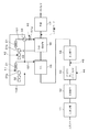
- FIG. 1 is a block diagram schematically showing a configuration example of an LNG plant.
- the liquid component contained in the NG produced from the well is separated by the gas-liquid separation unit 11, and then mercury is removed by the mercury removal unit 12.
- Subsequent acid gas removing unit 13 removes acid gas such as carbon dioxide and hydrogen sulfide.
- the acid gas removing unit 13 of this example the absorbing liquid containing the amine compound is brought into contact with NG to remove the acid gas. Further, by removing the water in the natural gas by the water removing unit 14, the removal of impurities from the NG before liquefaction is completed.
- the LNG plant shown in FIG. 1 is provided with a pre-cooling unit 15, in which the pre-cooling unit 15 precools NG before it is liquefied.
- a precooling refrigerant used for precooling NG a simple substance refrigerant of propane (C3 refrigerant) is used.
- the precooling unit 15 heat exchange between the NG and the precooling refrigerant is performed via a heat exchanger (not shown). Further, the precooling section 15 is provided with a precooling refrigerant cycle 151 in which the refrigerant vaporized by heat exchange is compressed by the refrigerant compressor 31a, cooled and liquefied by the cooler, and resupplied to the precooling section 15. In this example, an air-cooled heat exchanger (ACHE) 21 is used as these coolers.
- ACHE air-cooled heat exchanger
- a part of the precooling refrigerant is extracted from the precooling refrigerant cycle 151, and a refrigerant cooling cycle for cooling the liquefied refrigerant before being supplied to the liquefied / supercooled unit 16 in the subsequent stage. It has a structure with 152 attached.
- the precooling refrigerant flowing through the refrigerant cooling cycle 152 is returned to the inlet of the refrigerant compressor 31a on the precooling refrigerant cycle 151 side after the liquefiing refrigerant on the liquefying refrigerant cycle 161 side is cooled by the cooler 33.
- each refrigerant compressor 31a is driven by using a gas turbine (G / T) 32 as a driving machine (the same applies to the refrigerant compressor 31b of the liquefaction refrigerant cycle 161 described later).
- the liquefaction / supercooling unit 16 further cools the precooled NG and liquefies it.
- the refrigerant used for NG liquefaction / supercooling includes nitrogen, methane, ethane, ethylene, and propane. , Butane, Isopentane, and the like, a mixed refrigerant (MR: Mixed Refrigerant) containing a refrigerant component selected from the above is used.
- the liquefaction / supercooling unit 16 heat exchange between the NG and the above-mentioned refrigerant is performed via a heat exchanger (not shown). Further, the liquefaction / supercooling unit 16 compresses the refrigerant vaporized by heat exchange with the refrigerant compressor 31b, cools and liquefies the refrigerant with the cooler, and resupplyes the liquefaction / supercooling unit 16 to the liquefaction / supercooling unit 16. I have. In this example, ACHE2 is also used as these coolers.
- the product LNG obtained in the LNG plant is stored in the LNG tank 13 and then shipped to the outside via an LNG tanker or the like.
- LNG tanker or the like.
- FIG. 1 it is assumed that there are two LNG plants (A train and B train) shown in FIG.
- a large number of devices are provided in the LNG plant having the above configuration. And, among these devices, there are those whose operation is controlled so that the operation values such as the flow rate of the processing fluid, the pressure and the driving force of the power equipment are within the range of the preset operation constraints.
- the device subject to such operation control is referred to as a "device subject to control”
- the item that becomes an operation constraint is referred to as a "constraint item”.
- the operation analysis method of the LNG plant in this example focuses on the relationship between the constraint items of these controlled devices and the LNG production amount.
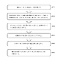
- the procedure for implementing the operation analysis method will be described with reference to FIG.
- the operation data of the controlled device and the LNG production amount data provided in the LNG plant are acquired (process P1 in FIG. 2).
- the operating value of each controlled device installed in the LNG plant is per unit time (for example, every 1 minute, every 5 minutes, or every 15 minutes) via a plant control system such as DCS (Distributed Control System). It is acquired as operation data in chronological order.
- the production amount data per unit time indicating the production amount of LNG is also acquired in chronological order.
- process P2 in FIG. 2 it is determined whether or not there is a controlled device that violates the driving constraint (process P2 in FIG. 2). Specifically, paying attention to the correspondence between the operation data of the controlled device and the production data, when the production amount data is less than the preset standard production amount (for example, the full production amount) (production reduction occurs). If so), it is determined whether or not there is a controlled device that violates the operation constraint at the time when the production amount data is acquired. By this determination, it is possible to identify the restricted device that caused the reduction in LNG production and the restricted item (bottleneck) that conflicted with the operation constraint at that time.
- the preset standard production amount for example, the full production amount
- the constraint item of the operation constraint that analyzes the relationship with the production volume data the constraint item that is conventionally known to be a factor of production reduction may be selected. Further, the operator involved in the operation of the LNG plant may be interviewed to identify and select the constraint items for which the operation adjustment for reducing the production has to be performed. In addition, all operation data of the LNG plant is acquired, and the operation restrictions that conflicted with the operation restrictions during the period when the production was reduced are uniformly applied without judging whether there is a causal relationship with the production reduction. It may be extracted as a constraint item.
- the acid gas removing unit 13 that removes the acid gas by bringing the NG and the absorbing liquid into contact with each other, and the upper limit value of the supply flow rate of the absorbing liquid to the acid gas removing unit 13 (* 4 in FIG. 1).
- the acid gas removing unit 13 includes a contact tower for contacting the NG and the absorbing liquid and a regeneration tower for releasing the acid gas from the absorbing liquid to regenerate the absorbing liquid
- the "supply flow rate of the absorbing liquid” is , Refers to the "absorption liquid circulation amount" which is the supply flow rate from the regeneration tower to the absorption tower.
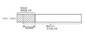
- (V) The upper limit of the acid gas content in the NG after being treated by the acid gas removing unit 13 and the acid gas removing unit 13 (* 5 in FIG. 1).
- the acid gas content is measured, for example, by an analyzer (not shown) arranged on the outlet side of the acid gas removing unit 13.
- a preset driving constraint range for example, an alarm alarm value setting range
- the driving data are used. Examples of methods for comparison can be illustrated. If the operation data is out of the range of the above operation constraint, it is determined that the operation constraint of the controlled device is violated.
- the alarm issuance record data set for the operation data together with the operation data is acquired in chronological order, and the period during which the alarm is issued violates the operation restrictions of the controlled device. You may judge that you did.
- the range of driving restrictions is not limited to the case where the setting range of the alarm alarm value is used.
- the operation value at which the operator voluntarily starts the production reduction may be grasped by hearing or the like and set as a threshold value within the range of the operation constraint.
- the length of the period during which the production was reduced is determined according to the magnitude of the production reduction (process P3 in FIG. 2).
- the magnitude of the production reduction is grasped by the ratio of the production amount data to the standard production amount and the difference value.
- the expression of production reduction is not particularly limited as long as the degree of production reduction can be grasped.
- the range of production reduction may be set as appropriate so that the degree of influence of each constraint item can be grasped collectively. For example, when full production is 100%, it is expressed as a production ratio such as "95% or more and less than 100%", or a daily conversion reduction such as "more than 0 tons / day and less than 10 tons / day". The case of expression can be illustrated.
- the length of the period during which the production was reduced is counted as one minute of each production reduction, and the period is integrated.
- the length of the production reduction period may be expressed as the period ratio (%) to the total period for which the operation data or production data was acquired, or a predetermined period such as one year or one month, or the total number of hours or the total number of minutes. It may be expressed.
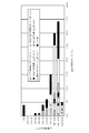
- FIG. 3 shows the result of the operation analysis on the A train side
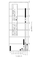
- FIG. 4 shows the result of the operation analysis on the B train side.
- the horizontal axis indicates the period during which the production cut occurred, and the ratio of the production cut occurrence time [% / year] during the operating period of one year is shown.
- the production reductions shown on the vertical axis are described by dividing the production amount ratio to the full production amount into a range of 5%.
- the A train has an upper limit of discharge pressure of the refrigerant compressor 31a for precooling refrigerant over a wide range in which the production amount is 75% or more and less than 100% (in FIG. 3). It can be seen that the bottleneck (described as "C3 compressor discharge pressure upper limit”) may cause a reduction in production.
- the upper limit of the discharge pressure of the refrigerant compressor 31a for precooling is a bottleneck, and the production is often reduced, but the production reduction is 85% or more. It can be seen that it is limited to the range of less than 100%. In addition, it can be seen that in the B train, the upper limit of the acid gas content becomes a bottleneck and the frequency of production reduction occurs less frequently than in the A train.
- the graphs shown in FIGS. 3 to 5 are examples of visualization of the operation analysis results, and graphs of other formats may be used. Instead of the length of each bar graph shown in FIGS. 3 and 4, the size of the circle in the pie chart represents the production reduction period, and an example shows the ratio of the constraint items that became bottlenecks in each pie chart. Further, it is not an indispensable requirement to visualize the operation analysis result by the graph, and the process P4 in FIG. 2 may be omitted and the latter stage examination may be performed based only on the operation analysis data.
- treatment P5 the effect of increasing production after eliminating each bottleneck is estimated.
- the amount of production increase when the bottleneck can be eliminated is specified by adding the result of multiplying each production reduction range by the production reduction period corresponding to the production reduction range. Then, the increase in profit expected from the increased production can be estimated as the effect of increased production.
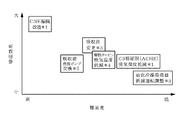
- FIG. 6 is a diagram in which various bottleneck eliminating means are plotted in association with the difficulty level of implementation and the effect of increasing production.
- the difficulty level shown on the horizontal axis is determined by comprehensively considering the cost required to eliminate the bottleneck, the construction period, and the ease of operation and maintenance.
- the effect of increasing production shown on the vertical axis can be obtained from the results of the above-mentioned operation analysis.
- the production amount data and the operation data of the LNG plant are associated with each other in chronological order, and the multiple operation constraint items (constraint items) are according to the magnitude of the production reduction. Since the length of the production reduction period (the period during which the production amount data was less than the standard production amount) is obtained, the degree of influence of each operation constraint item (bottleneck) on the production reduction can be clarified.
- the LNG plant to which the operation analysis method of this example can be applied is not limited to the example shown in FIG.
- a one-stage pressure MR type LNG plant may be used in which only the mixed refrigerant (MR), which is a liquefying refrigerant, is used without using the precooling refrigerant or the refrigerant cooling refrigerant (C3 refrigerant in this example).
- an LNG plant using a single liquefaction refrigerant (refrigerant raw material: nitrogen or methane) may be used.
- the precooling refrigerant is not limited to the case where a single refrigerant raw material such as propane or propylene is used, and a mixed refrigerant such as methane, ethane, propane or butane may be used.
- the LNG plant may be provided with a supercooler for supercooling LNG using a supercooling refrigerant using nitrogen or methane as a refrigerant raw material.
- this technology can also be applied to a cascade-type LNG plant that obtains LNG by sequentially cooling NG using a propane refrigerant, an ethylene refrigerant, and a methane refrigerant.
- the gas-liquid separation unit 11, the mercury removal unit 12, the acid gas removal unit 13, and the water removal unit 14 can also adopt various configuration examples.
- the acid gas may be removed by using a separation membrane module that separates the acid gas from NG.
- the operation analysis method of this example is also applied to a natural gas processing plant that separates and recovers at least one of LPG (Liquefied Petroleum Gas) and heavy components from natural gas and ships the light components in the gas state. can do.
- LPG Lified Petroleum Gas
- heavy components and gas are the products.
- Acid gas removal unit 15 Precooling unit 16 Liquefaction / supercooling unit 31a, 31b Refrigerant compressor 32 G / T
Landscapes
- Engineering & Computer Science (AREA)
- Business, Economics & Management (AREA)
- Physics & Mathematics (AREA)
- Mechanical Engineering (AREA)
- Thermal Sciences (AREA)
- General Engineering & Computer Science (AREA)
- Human Resources & Organizations (AREA)
- Economics (AREA)
- Strategic Management (AREA)
- Chemical Kinetics & Catalysis (AREA)
- General Chemical & Material Sciences (AREA)
- Chemical & Material Sciences (AREA)
- Oil, Petroleum & Natural Gas (AREA)
- Tourism & Hospitality (AREA)
- General Business, Economics & Management (AREA)
- General Physics & Mathematics (AREA)
- Theoretical Computer Science (AREA)
- Health & Medical Sciences (AREA)
- Marketing (AREA)
- Entrepreneurship & Innovation (AREA)
- Game Theory and Decision Science (AREA)
- Primary Health Care (AREA)
- General Health & Medical Sciences (AREA)
- Water Supply & Treatment (AREA)
- Public Health (AREA)
- Quality & Reliability (AREA)
- Operations Research (AREA)
- Educational Administration (AREA)
- Development Economics (AREA)
- Separation By Low-Temperature Treatments (AREA)
Abstract
Description
一方でこれらの機器は、外気温度やNGの供給圧力、NG組成などの外乱に応じて処理流体の流量、圧力や動力機器の駆動力などの運転状態が変化する。例えば大きな外乱の影響を受け、機器の運転状態が運転制約の管理範囲を外れるおそれがある場合には、このような運転状態を解消する運転調整を行う必要がある。
一方で、LNGプラントに設けられている機器の中で、その運転状態がLNG生産量に影響を及ぼす可能性のある機器は多数に及ぶ。このため、例えば年間を通じてのLNGプラントのフル生産が達成されていなかった場合に、減産の要因となった機器やその影響度が不明な場合もある。
前記製品の単位時間当たりの生産量データと、前記天然ガスプラントを構成し、予め設定された運転制約の範囲内で運転制御される複数の制御対象機器について、各制御対象機器が前記運転制約に抵触したか否かを判定するための運転データと、を時系列に対応付けて取得する工程と、
コンピュータにより、予め設定した、単位時間あたりの基準生産量と、前記生産量データとを比較し、当該生産量データが前記基準生産量未満である場合に、その生産量データを取得した時点にて、前記運転制約に抵触した制御対象機器があったか否かを判定し、前記抵触した制御対象機器があった場合には、当該制御対象機器に係る運転制約の項目を前記生産量データに対応付けるデータ処理を行う工程と、
前記運転制約の項目が対応付けられた生産量データと、前記基準生産量との差分である減産量を求め、各々の前記運転制約の項目について、前記減産量の大きさに応じて、前記生産量データが前記基準生産量未満であった期間の長さを求める工程と、を含むことを特徴とする。
(a)前記生産量データが前記基準生産量未満であった期間の長さと、前記減産量の大きさとの対応関係を、前記運転制約の項目ごとのグラフとして可視化する工程を含むこと。
(b)前記生産量データが前記基準生産量未満であった期間の長さを求める工程にて、前記生産量データに複数の前記運転制約の項目が対応付けられている場合には、これら運転制約の項目間に予め設定されている優先順位に基づき、優先順位の最も高い運転制約の項目について、前記生産量データが前記基準生産量未満であった期間に含めること。このとき、前記優先順位の最も高い運転制約の項目について、前記基準生産量未満であった期間に含められた前記生産量データに対し、残りの運転制約についての当該生産量データが前記基準生産量未満であった期間を重複して計算すること。
(c)前記天然ガスプラントは、天然ガスから液化天然ガスを製品として生産する液化天然ガスプラント、または、天然ガスからLPG(Liquefied Petroleum Gas)、重質分または軽質分の少なくとも一つを製品として分離・回収する天然ガス処理プラントであること。
(i)前記天然ガスプラントが前記天然ガスの予冷用冷媒の圧縮機を備えている場合の当該予冷用圧縮機と、前記予冷用圧縮機の吐出圧力上限値
(ii)前記天然ガスプラントが前記天然ガスの液化用冷媒の圧縮機を備えている場合の当該液化用圧縮機と、前記液化用圧縮機の駆動動力上限値
(iii)前記天然ガスプラントが前記液化用冷媒を用いて前記天然ガスを液化する場合の当該液化用冷媒の流量調節部と、前記液化用冷媒の流量上限値
(iv)前記天然ガスプラントが前記天然ガスと酸性ガスの吸収液とを接触させて、当該天然ガスに含まれる酸性ガスを除去する酸性ガス除去部を備えている場合の当該酸性ガス除去部と、前記酸性ガス除去部への前記吸収液の供給流量の上限値
(v)前記天然ガスプラントが前記天然ガスと酸性ガスの吸収液とを接触させて、当該天然ガスに含まれる酸性ガスを除去する酸性ガス除去部を備えている場合の当該酸性ガス除去部と、前記酸性ガス除去部にて処理され後の前記天然ガス中の酸性ガス含有量上限値
図1は、LNGプラントの構成例を模式的に示したブロック図である。LNGプラントは、井戸元より産出されたNG中に含まれる液体分を気液分離部11にて分離した後、水銀除去部12にて水銀を除去する。続く酸性ガス除去部13では、二酸化炭素や硫化水素などの酸性ガスの除去を行う。本例の酸性ガス除去部13においては、アミン化合物を含む吸収液とNGとを接触させて、酸性ガスの除去を行う。さらに、水分除去部14にて天然ガス中の水分を除去することにより、液化前のNGからの不純物の除去が完了する。
なお本例では、図1に示すLNGプラントが2系統(Aトレイン、Bトレイン)あるものとする。
以下、図2も参照しながら、当該稼働解析方法の実施手順について説明する。
LNGプラントに設けられている各制御対象機器の運転値は、DCS(Distributed Control System)などのプラント制御システムを介して、単位時間当たり(例えば1分や5分ごと、または15分ごとなど)の運転データとして時系列に沿って取得される。また、LNGの生産量を示す単位時間当たりの生産量データについても時系列に沿って取得される。
具体的には、制御対象機器の運転データと、生産データとの対応関係に着目し、生産量データが予め設定された基準生産量(例えばフル生産量)未満である場合(減産が発生している場合)に、その生産量データを取得した時点にて、運転制約に抵触した制御対象機器があったか否かを判定する。この判定により、LNGの減産の要因となった制約対象機器と、そのとき運転制約に抵触していた制約項目(ボトルネック)とを特定することができる。
(i)予冷用冷媒の圧縮機(予冷用圧縮機)31aと、当該冷媒圧縮機31aの吐出圧力上限値(図1の*1)
(ii)液化用冷媒の圧縮機(液化用圧縮機)31bと、当該冷媒圧縮機31bの駆動動力上限値(図1の*2)。
(iii)液化用冷媒の流量調節部161aと、液化用冷媒の流量上限値(図1の*3)。
(iv)NGと吸収液とを接触させて酸性ガスを除去する酸性ガス除去部13と、酸性ガス除去部13への吸収液の供給流量の上限値(図1の*4)。ここで、酸性ガス除去部13がNGと吸収液とを接触させる接触塔と、吸収液から酸性ガスを放出させて吸収液を再生する再生塔とを備える場合、「吸収液の供給流量」は、再生塔から吸収塔への供給流量である「吸収液循環量」を指す。
(v)酸性ガス除去部13と、酸性ガス除去部13にて処理され後のNG中の酸性ガス含有量上限値(図1の*5)。酸性ガス含有量は、例えば酸性ガス除去部13の出口側に配置された不図示の分析計により測定される。
なお、運転制約の範囲はアラーム発報値の設定範囲を用いる場合に限定されない。例えば、制御対象機器の運転変動の発生を回避するために、オペレータが自主的に減産を開始する運転値をヒアリングなどにより把握し、運転制約の範囲のしきい値としてもよい。
このとき、抵触の発生有無の判断を行っている制約項目(例えば図1の*1~*5)にて抵触が発生していないにも係らず、減産が発生している場合は、「その他」の制約項目に対応付けてもよい。
減産量の大きさは、基準生産量に対する生産量データの割合や、差分値により把握する。減産量の表現は減産の度合を把握することができれば特段の限定はない。また、各制約項目の影響度合いをまとめて把握できるように、適宜、減産量の範囲を設定してもよい。例えばフル生産を100%としたとき、「95%以上、100%未満」といった生産量割合で表現する場合や、「0トン/日超、10トン/日以下」といった日量換算の減産量で表現する場合を例示できる。
図3、図4は、図2の処理P1~P3を実施して解析した各制約項目について、減産が発生した期間(生産量データが基準生産量未満であった期間)の長さを減産量の大きさに応じて棒グラフにまとめた結果である。
この場合には図3、4に示す各制約項目(*1~*5)に対して優先順位を定めることができる。そして、より優先順位の高い制約項目についての減産期間算出のために用いられた生産量データは、残りの制約項目についての減産期間の算出には用いないようにしてもよい。
また、グラフによって稼働解析結果を可視化することは、必須の要件ではなく、図2の処理P4を省略し、稼働解析のデータのみに基づいて後段の検討を行ってもよい。
そして、これらの処理の結果をまとめた解析結果に基づき、各ボトルネック解消後の増産効果を推定する(処理P5)。ボトルネックごとに、各減産量範囲と、当該減産量範囲に対応する減産期間とを乗算した結果を足し合わせることにより、当該ボトルネックを解消できた場合の増産量を特定する。そして、当該増産量から見込まれる収益の増加分を増産効果と推定できる。
図6は、各種のボトルネック解消手段を、その実施難易度と、増産効果とに対応付けてプロットした図である。横軸に示す難易度は、ボトルネックの解消に必要な費用や工期、運転やメンテナンスのしやすさなどを総合的に考慮して定められる。縦軸に示す増産効果は、上述の稼働解析の結果から求めることができる。
図3、4に示すデータ処理の結果を用いることにより、各施策についての費用対効果が明確になり、より効果的な施策を選定するための判断材料を提供することができる。
この場合には、図3、4中に「C3圧縮機吐出上限(*1)」と記されたボトルネックに起因する減産の一部を解消できる。これに加えて、上述の例のような運転調整の実施に伴って「その他」の要因に計上された減産の一部を解消することもできる。
例えば予冷用冷媒や冷媒冷却用冷媒(本例ではC3冷媒)を用いず、液化用冷媒である混合冷媒(MR)のみを用いた1段階圧力式MR方式のLNGプラントであってもよい。
この他、プロパン冷媒、エチレン冷媒、メタン冷媒を用いて、NGを順次、冷却することによりLNGを得るカスケード方式のLNGプラントに対しても、本技術を適用することができる。
15 予冷部
16 液化・過冷却部
31a、31b
冷媒圧縮機
32 G/T
Claims (6)
- 天然ガスから製品を生産する天然ガスプラントの稼働解析方法であって、
前記製品の単位時間当たりの生産量データと、前記天然ガスプラントを構成し、予め設定された運転制約の範囲内で運転制御される複数の制御対象機器について、各制御対象機器が前記運転制約に抵触したか否かを判定するための運転データと、を時系列に対応付けて取得する工程と、
コンピュータにより、予め設定した、単位時間あたりの基準生産量と、前記生産量データとを比較し、当該生産量データが前記基準生産量未満である場合に、その生産量データを取得した時点にて、前記運転制約に抵触した制御対象機器があったか否かを判定し、前記抵触した制御対象機器があった場合には、当該制御対象機器に係る運転制約の項目を前記生産量データに対応付けるデータ処理を行う工程と、
前記運転制約の項目が対応付けられた生産量データと、前記基準生産量との差分である減産量を求め、各々の前記運転制約の項目について、前記減産量の大きさに応じて、前記生産量データが前記基準生産量未満であった期間の長さを求める工程と、を含むことを特徴とする天然ガスプラントの稼働解析方法。 - 前記生産量データが前記基準生産量未満であった期間の長さと、前記減産量の大きさとの対応関係を、前記運転制約の項目ごとのグラフとして可視化する工程を含むことを特徴とする請求項1に記載の天然ガスプラントの稼働解析方法。
- 前記生産量データが前記基準生産量未満であった期間の長さを求める工程にて、前記生産量データに複数の前記運転制約の項目が対応付けられている場合には、これら運転制約の項目間に予め設定されている優先順位に基づき、優先順位の最も高い運転制約の項目について、前記生産量データが前記基準生産量未満であった期間に含めることを特徴とする請求項1に記載の天然ガスプラントの稼働解析方法。
- 前記優先順位の最も高い運転制約の項目について、前記基準生産量未満であった期間に含められた前記生産量データに対し、残りの運転制約についての当該生産量データが前記基準生産量未満であった期間を重複して計算することを特徴とする請求項3に記載の天然ガスプラントの稼働解析方法。
- 前記天然ガスプラントは、天然ガスから液化天然ガスを製品として生産する液化天然ガスプラント、または、天然ガスからLPG(Liquefied Petroleum Gas)、重質分または軽質分の少なくとも一つを製品として分離・回収する天然ガス処理プラントであることを特徴とする請求項1に記載の天然ガスプラントの稼働解析方法。
- 前記制御対象機器と、その運転制約の項目との組み合わせは、下記(i)~(v)の組み合わせ群から選択した少なくとも1つの組み合わせを含んでいることを特徴とする請求項1に記載の天然ガスプラントの稼働解析方法。
(i)前記天然ガスプラントが前記天然ガスの予冷用冷媒の圧縮機を備えている場合の当該予冷用圧縮機と、前記予冷用圧縮機の吐出圧力上限値
(ii)前記天然ガスプラントが前記天然ガスの液化用冷媒の圧縮機を備えている場合の当該液化用圧縮機と、前記液化用圧縮機の駆動動力上限値
(iii)前記天然ガスプラントが前記液化用冷媒を用いて前記天然ガスを液化する場合の当該液化用冷媒の流量調節部と、前記液化用冷媒の流量上限値
(iv)前記天然ガスプラントが前記天然ガスと酸性ガスの吸収液とを接触させて、当該天然ガスに含まれる酸性ガスを除去する酸性ガス除去部を備えている場合の当該酸性ガス除去部と、前記酸性ガス除去部への前記吸収液の供給流量の上限値
(v)前記天然ガスプラントが前記天然ガスと酸性ガスの吸収液とを接触させて、当該天然ガスに含まれる酸性ガスを除去する酸性ガス除去部を備えている場合の当該酸性ガス除去部と、前記酸性ガス除去部にて処理され後の前記天然ガス中の酸性ガス含有量上限値
Priority Applications (4)
| Application Number | Priority Date | Filing Date | Title |
|---|---|---|---|
| PCT/JP2019/027381 WO2021005754A1 (ja) | 2019-07-10 | 2019-07-10 | 天然ガスプラントの稼働解析方法 |
| AU2019456245A AU2019456245B2 (en) | 2019-07-10 | 2019-07-10 | Operation analysis method of natural gas plant |
| US17/625,092 US12092395B2 (en) | 2019-07-10 | 2019-07-10 | Operation analysis method for natural gas plant |
| JP2021530430A JP7116392B2 (ja) | 2019-07-10 | 2019-07-10 | 天然ガスプラントの稼働解析方法 |
Applications Claiming Priority (1)
| Application Number | Priority Date | Filing Date | Title |
|---|---|---|---|
| PCT/JP2019/027381 WO2021005754A1 (ja) | 2019-07-10 | 2019-07-10 | 天然ガスプラントの稼働解析方法 |
Publications (1)
| Publication Number | Publication Date |
|---|---|
| WO2021005754A1 true WO2021005754A1 (ja) | 2021-01-14 |
Family
ID=74115036
Family Applications (1)
| Application Number | Title | Priority Date | Filing Date |
|---|---|---|---|
| PCT/JP2019/027381 Ceased WO2021005754A1 (ja) | 2019-07-10 | 2019-07-10 | 天然ガスプラントの稼働解析方法 |
Country Status (4)
| Country | Link |
|---|---|
| US (1) | US12092395B2 (ja) |
| JP (1) | JP7116392B2 (ja) |
| AU (1) | AU2019456245B2 (ja) |
| WO (1) | WO2021005754A1 (ja) |
Citations (5)
| Publication number | Priority date | Publication date | Assignee | Title |
|---|---|---|---|---|
| JPS6325481A (ja) * | 1986-07-10 | 1988-02-02 | エア・プロダクツ・アンド・ケミカルズ・インコ−ポレイテツド | 多成分冷媒系の自動制御システム |
| JP2012185743A (ja) * | 2011-03-07 | 2012-09-27 | Mitsubishi Heavy Ind Ltd | 生産能力評価装置、生産能力評価方法および生産能力評価プログラム |
| WO2017154181A1 (ja) * | 2016-03-10 | 2017-09-14 | 日揮株式会社 | 天然ガス液化装置の混合冷媒組成の決定方法 |
| JP2018032396A (ja) * | 2016-08-18 | 2018-03-01 | i Smart Technologies株式会社 | 稼働状態取得装置、製造ラインの生産管理システムおよび生産管理方法 |
| US20180356151A1 (en) * | 2017-06-08 | 2018-12-13 | General Electric Company | Methods and systems for enhancing production of liquefied natural gas |
Family Cites Families (1)
| Publication number | Priority date | Publication date | Assignee | Title |
|---|---|---|---|---|
| WO2019097728A1 (ja) | 2017-11-20 | 2019-05-23 | 日揮株式会社 | 天然ガス液化装置の運転方法 |
-
2019
- 2019-07-10 US US17/625,092 patent/US12092395B2/en active Active
- 2019-07-10 AU AU2019456245A patent/AU2019456245B2/en active Active
- 2019-07-10 JP JP2021530430A patent/JP7116392B2/ja active Active
- 2019-07-10 WO PCT/JP2019/027381 patent/WO2021005754A1/ja not_active Ceased
Patent Citations (5)
| Publication number | Priority date | Publication date | Assignee | Title |
|---|---|---|---|---|
| JPS6325481A (ja) * | 1986-07-10 | 1988-02-02 | エア・プロダクツ・アンド・ケミカルズ・インコ−ポレイテツド | 多成分冷媒系の自動制御システム |
| JP2012185743A (ja) * | 2011-03-07 | 2012-09-27 | Mitsubishi Heavy Ind Ltd | 生産能力評価装置、生産能力評価方法および生産能力評価プログラム |
| WO2017154181A1 (ja) * | 2016-03-10 | 2017-09-14 | 日揮株式会社 | 天然ガス液化装置の混合冷媒組成の決定方法 |
| JP2018032396A (ja) * | 2016-08-18 | 2018-03-01 | i Smart Technologies株式会社 | 稼働状態取得装置、製造ラインの生産管理システムおよび生産管理方法 |
| US20180356151A1 (en) * | 2017-06-08 | 2018-12-13 | General Electric Company | Methods and systems for enhancing production of liquefied natural gas |
Also Published As
| Publication number | Publication date |
|---|---|
| AU2019456245A1 (en) | 2022-01-27 |
| US20220276000A1 (en) | 2022-09-01 |
| US12092395B2 (en) | 2024-09-17 |
| JP7116392B2 (ja) | 2022-08-10 |
| AU2019456245B2 (en) | 2025-08-28 |
| JPWO2021005754A1 (ja) | 2021-01-14 |
Similar Documents
| Publication | Publication Date | Title |
|---|---|---|
| EP2162691B1 (en) | Apparatus and method for optimizing a liquefied natural gas facility | |
| US10012432B2 (en) | Method and apparatus for cooling a hydrocarbon stream | |
| CN102483695B (zh) | 在具有平行序列的气体装置中的制冷系统控制方法 | |
| RU2686355C1 (ru) | Способ определения состава смешанного хладагента для установки сжижения природного газа | |
| Sanavandi et al. | Normalized sensitivity analysis of LNG processes-Case studies: Cascade and single mixed refrigerant systems | |
| US10161675B2 (en) | Natural gas liquefaction system | |
| CN102265104A (zh) | 冷却烃物流的方法及其设备 | |
| JP7116392B2 (ja) | 天然ガスプラントの稼働解析方法 | |
| WO2021240689A1 (ja) | 液化天然ガスプラントの運転条件決定方法及びそのシステム | |
| WO2019097571A1 (ja) | 天然ガス液化装置、及び天然ガス液化装置の設計方法 | |
| AU2017341387B2 (en) | System for treating and cooling a hydrocarbon stream | |
| AU2019448524B2 (en) | Operation analysis method for production plant | |
| Bachtiar et al. | Techno-Economic and Feasibility Assessment of Cryogenic Distillation Membrane (CDM) for Purification Natural Gas from CO2 | |
| WO2019097728A1 (ja) | 天然ガス液化装置の運転方法 | |
| US11874056B2 (en) | Operation guidance searching method and operation guidance searching system | |
| KOULA | Estimation of the reliability law in the LNG1 production system and development of an Odoo tool for ameliorative maintenance | |
| US12491465B2 (en) | Apparatus and process for removal of heavy hydrocarbons from a feed gas | |
| Fahimirad et al. | A three-stage scenario based operational performance test approaches for production capacity enhancement: Case study on the 5th refinery of South Pars Gas Complex in Iran | |
| CA3039937C (en) | System for treating and cooling a hydrocarbon stream | |
| Raghuraman et al. | ADGAS LNG Train-3 APC Implementation |
Legal Events
| Date | Code | Title | Description |
|---|---|---|---|
| 121 | Ep: the epo has been informed by wipo that ep was designated in this application |
Ref document number: 19936642 Country of ref document: EP Kind code of ref document: A1 |
|
| ENP | Entry into the national phase |
Ref document number: 2021530430 Country of ref document: JP Kind code of ref document: A |
|
| NENP | Non-entry into the national phase |
Ref country code: DE |
|
| ENP | Entry into the national phase |
Ref document number: 2019456245 Country of ref document: AU Date of ref document: 20190710 Kind code of ref document: A |
|
| 122 | Ep: pct application non-entry in european phase |
Ref document number: 19936642 Country of ref document: EP Kind code of ref document: A1 |