WO2021005742A1 - 注視点検出装置及び注視点検出方法 - Google Patents
注視点検出装置及び注視点検出方法 Download PDFInfo
- Publication number
- WO2021005742A1 WO2021005742A1 PCT/JP2019/027305 JP2019027305W WO2021005742A1 WO 2021005742 A1 WO2021005742 A1 WO 2021005742A1 JP 2019027305 W JP2019027305 W JP 2019027305W WO 2021005742 A1 WO2021005742 A1 WO 2021005742A1
- Authority
- WO
- WIPO (PCT)
- Prior art keywords
- image
- photographing unit
- target person
- depth information
- unit
- Prior art date
- Legal status (The legal status is an assumption and is not a legal conclusion. Google has not performed a legal analysis and makes no representation as to the accuracy of the status listed.)
- Ceased
Links
Images



Classifications
-
- G—PHYSICS
- G06—COMPUTING OR CALCULATING; COUNTING
- G06F—ELECTRIC DIGITAL DATA PROCESSING
- G06F3/00—Input arrangements for transferring data to be processed into a form capable of being handled by the computer; Output arrangements for transferring data from processing unit to output unit, e.g. interface arrangements
- G06F3/01—Input arrangements or combined input and output arrangements for interaction between user and computer
- G06F3/011—Arrangements for interaction with the human body, e.g. for user immersion in virtual reality
- G06F3/013—Eye tracking input arrangements
-
- G—PHYSICS
- G06—COMPUTING OR CALCULATING; COUNTING
- G06T—IMAGE DATA PROCESSING OR GENERATION, IN GENERAL
- G06T7/00—Image analysis
- G06T7/70—Determining position or orientation of objects or cameras
-
- G—PHYSICS
- G06—COMPUTING OR CALCULATING; COUNTING
- G06T—IMAGE DATA PROCESSING OR GENERATION, IN GENERAL
- G06T7/00—Image analysis
- G06T7/97—Determining parameters from multiple pictures
-
- G—PHYSICS
- G06—COMPUTING OR CALCULATING; COUNTING
- G06V—IMAGE OR VIDEO RECOGNITION OR UNDERSTANDING
- G06V40/00—Recognition of biometric, human-related or animal-related patterns in image or video data
- G06V40/10—Human or animal bodies, e.g. vehicle occupants or pedestrians; Body parts, e.g. hands
- G06V40/16—Human faces, e.g. facial parts, sketches or expressions
- G06V40/161—Detection; Localisation; Normalisation
-
- G—PHYSICS
- G06—COMPUTING OR CALCULATING; COUNTING
- G06V—IMAGE OR VIDEO RECOGNITION OR UNDERSTANDING
- G06V40/00—Recognition of biometric, human-related or animal-related patterns in image or video data
- G06V40/10—Human or animal bodies, e.g. vehicle occupants or pedestrians; Body parts, e.g. hands
- G06V40/18—Eye characteristics, e.g. of the iris
- G06V40/193—Preprocessing; Feature extraction
-
- H—ELECTRICITY
- H04—ELECTRIC COMMUNICATION TECHNIQUE
- H04N—PICTORIAL COMMUNICATION, e.g. TELEVISION
- H04N23/00—Cameras or camera modules comprising electronic image sensors; Control thereof
- H04N23/60—Control of cameras or camera modules
-
- G—PHYSICS
- G06—COMPUTING OR CALCULATING; COUNTING
- G06T—IMAGE DATA PROCESSING OR GENERATION, IN GENERAL
- G06T2207/00—Indexing scheme for image analysis or image enhancement
- G06T2207/10—Image acquisition modality
- G06T2207/10028—Range image; Depth image; 3D point clouds
-
- G—PHYSICS
- G06—COMPUTING OR CALCULATING; COUNTING
- G06T—IMAGE DATA PROCESSING OR GENERATION, IN GENERAL
- G06T2207/00—Indexing scheme for image analysis or image enhancement
- G06T2207/30—Subject of image; Context of image processing
- G06T2207/30196—Human being; Person
- G06T2207/30201—Face
Definitions
- the present invention relates to a gaze point detecting device and a gaze point detection method for detecting an object that a person is gazing at.
- the gaze point detecting device based on the gaze point detection technique includes one or a plurality of cameras that estimate the position and the line-of-sight direction of the person to be gaze detection.
- the position of the target person is estimated using geometric techniques from the images taken and recorded by the camera. Alternatively, the position of the target person is estimated using a position estimation detector.
- the line-of-sight direction is estimated using a line-of-sight detector. Then, the point of interest of the target person is estimated by detecting the object ahead in the line-of-sight direction.
- Patent Document 1 describes a device for detecting the gaze point.
- the device described in Patent Document 1 detects a gazing point by using one camera for photographing a target person and a line-of-sight direction detecting means.
- the device described in Patent Document 1 cannot strictly measure the spatial position and size of the pupil of the target person, which is the origin of the line of sight, and the depth of the image. Therefore, the device described in Patent Document 1 can acquire the line-of-sight angle of the target person, but cannot accurately detect the gazing point.
- An object of the present invention is to provide a gaze point detection system capable of accurately detecting a gaze point.
- the gazing point detection device has the first image and the first depth information acquired by the first photographing unit, which acquires the image and the depth information in the range including at least the second photographing unit, and the first The second image and the second depth information acquired by the second photographing unit, which are located so as to face the photographing unit and acquire at least the image in the range including the first photographing unit and the depth information.
- a line-of-sight direction that is input and estimates the line-of-sight direction of the target person using the face detection means that detects the face part of the target person from the first image and the first depth information and the face part detected by the face detection means.
- the estimation means Based on the estimation means, the first image, the first depth information, the second image, and the second depth information, the three-dimensional spatial position of the pupil of the target person, the first photographing unit, and the second photographing portion. It includes a position information estimating means for estimating the three-dimensional spatial position of the unit, and a gaze point specifying means for specifying the gaze point of the target person based on the three-dimensional spatial position of the pupil of the target person and the line-of-sight direction.
- the first image and the first depth information acquired by the first photographing unit which acquires at least the image and the depth information in the range including the second photographing unit
- the first The second image and the second depth information acquired by the second photographing unit which are located so as to face the photographing unit and acquire at least the image in the range including the first photographing unit and the depth information.
- Input detect the face part of the target person from the first image and the first depth information, estimate the line-of-sight direction of the target person using the detected face part, and use the first image and the first depth.
- the three-dimensional spatial position of the pupil of the target person and the three-dimensional spatial position of the first photographing unit and the second photographing unit are estimated, and the target person The gaze point of the target person is specified based on the three-dimensional spatial position of the pupil and the direction of the line of sight.
- the gazing point detection program includes a first image and a first depth information acquired by a first photographing unit that acquires an image and depth information in a range including at least a second photographing unit in a computer.
- the second image and the second depth acquired by the second photographing unit which are located so as to face the first photographing unit and acquire the image and the depth information in the range including at least the first photographing unit.
- the three-dimensional spatial position of the pupil of the target person and the three dimensions of the first photographing part and the second photographing part Based on the first image and the first depth information and the second image and the second depth information, the three-dimensional spatial position of the pupil of the target person and the three dimensions of the first photographing part and the second photographing part.
- the process of estimating the spatial position and the process of specifying the gazing point of the target person based on the three-dimensional spatial position of the target person's pupil and the line-of-sight direction are executed.
- the accuracy of the spatial position information of the target person is improved, and the gazing point can be detected with high accuracy.
- FIG. 1 is a block diagram showing the gazing point detection device 10 of the first embodiment together with the first photographing unit 101 and the second photographing unit 102.
- the gaze point detection device 10 includes an image storage unit 104, a face detection unit 105, a line-of-sight direction estimation unit 106, a position information estimation unit 107, and a gaze target estimation unit 108.
- Depth cameras are used as the first photographing unit 101 and the second photographing unit 102, respectively.
- the depth camera means a photographing means capable of acquiring distance information (depth information) as well as an RGB image (two-dimensional image).
- RGB-D camera a depth camera
- Intel Real Sense registered trademark
- the first photographing unit 101 and the second photographing unit 102 can be used as the first photographing unit 101 and the second photographing unit 102.
- the depth camera a combination of a camera that acquires an RGB image and a ToF (Time of Flight) camera may be used.
- the first photographing unit 101 is installed at a position where the target person can photograph the front side of the target person when gazing at the target.
- the first photographing unit 101 is adjusted to a height or angle sufficient for the person's face to enter the image.
- the second photographing unit 102 is installed so as to include the gaze portion to be detected behind the first photographing unit 101 in the image. Further, the first photographing unit 101 and the second photographing unit 102 are installed so that a constant shield or the like does not enter the photographed image.
- FIG. 2 shows an arrangement example of the first photographing unit 101 and the second photographing unit 102.
- the first photographing unit 101 is installed so that the target person 1 and the second photographing unit 102 are included in the image obtained by the first photographing unit 101.
- the second photographing unit 102 is installed so that the target person 1 and the first photographing unit 101 are included in the image obtained by the second photographing unit 102.
- the first photographing unit 101 and the second photographing unit 102 are arranged so as to face each other.
- the line-of-sight direction of the target person 1 is estimated from the image of the front of the target person 1 taken by the first photographing unit 101.
- the target to be watched by the target person 1 is specified from the image of the back surface of the target person 1 and the candidate of the target to be watched by the target person 1 taken by the second photographing unit 102.
- the first imaging unit 101 and the second imaging unit 102 work together, that is, based on both the image captured by the first imaging unit 101 and the image captured by the second imaging unit 102. Since the target person 1 identifies the object to be watched, it is required that the coordinates in the image captured by the first photographing unit 101 and the coordinates in the image captured by the second photographing unit 102 match. To.
- the first photographing unit 101 acquires at least an image (two-dimensional image) of the face portion of the target person and the second photographing unit 102, and depth information.
- the second photographing unit 102 acquires images and depth information of the target person, the first photographing unit 101, and the gaze target of the target person.
- the image storage unit 104 records (stores) image information and depth information captured by the second imaging unit 102.
- the face detection unit 105 detects the face of the target person from the image taken by the first photographing unit 101.
- the line-of-sight direction estimation unit 106 estimates the line-of-sight direction from the face image detected by the face detection unit 105.
- the position information estimation unit 107 is based on the images and depth information captured by the first imaging unit 101 and the second imaging unit 102, and the spatial positions of the target person, the first imaging unit 101, and the second imaging unit 102 ( Estimate the three-dimensional space position).
- the gaze target estimation unit 108 estimates the gaze target using the gaze information obtained by the gaze direction estimation unit 106 and the spatial position obtained by the position information estimation unit 107.
- the gaze target estimation unit 108 adds a gaze target to the image of the second photographing unit 102 from which the shielding portion has been removed using the past image recorded in the image storage unit 104. Details of the past image and the shielded portion will be described later.
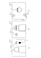
- FIG. 3 is an explanatory diagram showing an example of images taken by the first photographing unit 101 and the second photographing unit 102.
- FIG. 3A shows an example of the image 302 taken by the second photographing unit 102.
- FIG. 3B shows an example of the image 301 taken by the first photographing unit 101.
- the image 301 is an image in which the front side of the target person 1 and the second photographing unit 102 are photographed.
- the image 302 is an image in which the back side of the target person 1, the first photographing unit 101, and the gaze target 2 are photographed.
- FIG. 4 is an explanatory diagram showing how the shielded portion is restored by using the images taken in the past by the second photographing unit 102.
- FIG. 4A shows an example of the image 402 taken by the second photographing unit 102.
- FIG. 4B shows an example of an image 412 including an image of the gaze target 2.
- the image of the first photographing unit 101 is omitted.
- the first photographing unit 101 is installed, for example, on the customer aisle side of the product display shelf.
- the second photographing unit 102 is installed, for example, on the opposite side of the customer passage from the product display shelf on which the first photographing unit 101 is installed.
- the target person 1 customer in this example
- the gaze point detecting device 10 also controls so that the image of the gaze target 2 appears in the image 412 even in such a case.
- FIG. 5 is a flowchart showing the operation of the gazing point detection device 10.
- the first photographing unit 101 and the second photographing unit 102 in the gazing point detection device 10 are arranged so as to face each other (step S100).
- step S101 The process of step S101 is executed, for example, as follows.
- the position information estimation unit 107 obtains the position (three-dimensional space position) of the second photographing unit 102 from the image and depth information photographed by the first photographing unit 101. Further, the gaze target estimation unit 108 obtains the position of the first photographing unit 101 from the image and depth information photographed by the second photographing unit 102. The position information estimation unit 107 obtains a position vector of the first photographing unit 101 whose origin is the position of the second photographing unit 102 based on the image and depth information photographed by the first photographing unit 101. Further, the position information estimation unit 107 obtains a position vector of the second photographing unit 102 having the position of the first photographing unit 101 as the origin based on the image and depth information photographed by the second photographing unit 102.
- the magnitudes of the two position vectors that is, the distances, match. If they do not match, the two position vectors are normalized by averaging the magnitudes of the two position vectors.
- the gaze target estimation unit 108 calculates the rotation matrix R based on the following equation (1).
- r 14 indicates the position of the second photographing unit 102 based on the image and depth information photographed by the first photographing unit 101 when the position of the first photographing unit 101 is the origin.
- r 41 indicates the position of the first photographing unit 101 based on the image and depth information photographed by the second photographing unit 102 when the position of the second photographing unit 102 is the origin.
- the rotation matrix R can be obtained exactly by solving the nonlinear simultaneous equations. The accuracy of the numerical solution of nonlinear simultaneous equations increases as the number of parameters decreases.
- the lines horizontal and perpendicular to the ground, the three-dimensional spatial positions of the first photographing unit 101 and the second photographing unit 102, and the like are identified in advance (for example, assuming the application of the gazing point detection device 10 to a store). If a part of the rotation angle is obtained by another method by arranging the steps of the product display shelves so as to be horizontal to the ground or making the appearance of the product display shelves rectangular parallelepiped, the accuracy of the numerical solution will be improved. improves.
- step S101 may be executed every time the process of detecting the target to be watched by the target person 1 is executed, but it may be executed periodically (for example, once a day) or the first step. It may be executed at the time of installation of the photographing unit 101 and the second photographing unit 102.
- the face detection unit 105 detects the face portion of the target person from the image captured by the first photographing unit 101 (step S102).
- the face detection unit 105 can use, for example, the face detection function of OpenCV when detecting the face portion.
- the line-of-sight direction estimation unit 106 estimates the line-of-sight direction based on the face image detected by the face detection unit 105 (step S103).
- the line-of-sight direction estimation unit 106 can use, for example, the corneal reflex method when estimating the line-of-sight direction.
- the corneal reflex method an infrared light source or a near infrared light source is used in combination.
- the position information estimation unit 107 is based on the images and depth information captured by the first imaging unit 101 and the second imaging unit 102, and the pupil of the target person 1, the first imaging unit 101, and the second imaging unit 102.
- the three-dimensional spatial position is estimated (step S104).
- the position information estimation unit 107 detects the position of the pupil in the image using, for example, the Facemark API of OpenCV, and internally calibrates the depth camera in the first photographing unit 101. As a result, the position information of the pupil can be obtained geometrically.
- the image storage unit 104 records an image (past image) taken by the second photographing unit 102 in a situation where the target person 1 does not exist.
- the position information estimation unit 107 replaces the portion of the object that shields the gaze target 2 in the current image (that is, the image in which the target person 1 is captured) captured by the second imaging unit 102 with the corresponding portion in the past image.
- the object that shields the gaze target 2 is mainly the target person 1.
- An image in which the corresponding portion is replaced in the past image (an image in which the corresponding portion is replaced in the current image taken by the second photographing unit 102) is hereinafter referred to as a replacement image.
- the past image is an image taken by the second photographing unit 102 in a state where there is no obstacle such as the target person 1.
- the gaze target estimation unit 108 detects the gaze target using the gaze direction estimated by the gaze direction estimation unit 106 and the spatial position information estimated by the position information estimation unit 107.
- the gaze target estimation unit 108 extends a straight line in the line-of-sight direction from the three-dimensional space position of the pupil, for example (step S106). When the straight line intersects with some object in the replacement image, the gaze target estimation unit 108 determines that the object is the gaze target (step S107).
- the gaze target estimation unit 108 shields the gaze target 2 from the target person 1 in the current image (that is, the image in which the target person 1 is captured) taken by the second photographing unit 102. Even in this case, the gaze target 2 can be specified without hiding the gaze target 2 from the target person 1.
- the gaze target estimation unit 108 adds the gaze target in the replacement image (step S108: see FIG. 4B)).
- the gaze target estimation unit 108 plots the coordinate values in the coordinate system of the second photographing unit 102 on the image captured by the second photographing unit 102.
- the gaze target estimation unit 108 may display an image on which the gaze target of the target person is displayed on the display device.
- the position of the gaze target 2 is higher than in the case of estimating the depth information from one image. It becomes possible to estimate with accuracy. Further, by combining the depth information acquired by the plurality of photographing units (the first photographing unit 101 and the second photographing unit 102), the noise of the depth information can be canceled (for example, with the first photographing unit 101). When averaging the magnitudes of two position vectors with the second photographing unit 102).
- the two photographing units that sandwich the target person 1 are utilized, it is possible to detect the position of the gaze target 2 that cannot be detected when a single camera is used. Further, since the replacement image is used, the position of the gaze target 2 can be estimated even when the gaze target 2 is shielded.
- FIG. 6 is a block diagram showing a configuration example of the gazing point detection device 20 of the second embodiment together with the first photographing unit 101, the second photographing unit 102, and the third photographing unit 103.
- the gazing point detection device 20 is basically configured in the same manner as the gazing point detecting device 10 of the first embodiment, but in the present embodiment, the position information estimation unit 107 is photographed by the third photographing unit 103. Images are also used. A two-dimensional camera that does not acquire depth information may be used as the third photographing unit 103.
- FIG. 7 is an explanatory diagram showing an arrangement example of the first photographing unit 101, the second photographing unit 102, and the third photographing unit 103.
- the first photographing unit 101 is installed at a position where the front side of the target person can be photographed when the target person gazes at the target.
- the first photographing unit 101 is adjusted to a height or angle sufficient for the person's face to enter the image.
- the second photographing unit 102 is installed so as to include the gaze portion to be detected behind the first photographing unit 101 in the image. Further, the first photographing unit 101 and the second photographing unit 102 are installed so that a constant shield or the like does not enter the photographed image.
- first photographing unit 101 is installed so that the second photographing unit 102 is included in the image obtained by the first photographing unit 101.
- the second photographing unit 102 is installed so that the first photographing unit 101 is included in the image obtained by the second photographing unit 102.
- the first photographing unit 101 acquires at least an image (two-dimensional image) of the face portion of the target person and the second photographing unit 102, and depth information.
- the second photographing unit 102 acquires images and depth information of the target person, the first photographing unit 101, and the gaze target of the target person.
- the image storage unit 104 records (stores) image information and depth information captured by the second imaging unit 102.
- the third photographing unit 103 is installed at a position where the first photographing unit 101, the second photographing unit 102, and the target person 1 can be photographed.
- the third photographing unit 103 photographs an image in which the first photographing unit 101, the second photographing unit 102, and the target person 1 are captured, and the depth information thereof may be acquired.
- FIG. 8 is a flowchart showing the operation of the gazing point detection device 20 of the second embodiment. In the flowchart shown in FIG. 8, the processes of steps S201 and S202 are added to the flowchart shown in FIG.
- the first photographing unit 101 and the second photographing unit 102 in the gazing point detection device 10 are arranged so as to face each other (step S100). Further, the third photographing unit 103 is installed at a position where the first photographing unit 101, the second photographing unit 102, and the target person 1 can be photographed (step S201). The processing of steps S101 to S103 is the same as the processing in the first embodiment.
- the position information estimation unit 107 captures the pupil of the target person 1 and the first image from the images and depth information captured by the first imaging unit 101 and the second imaging unit 102. After estimating the three-dimensional spatial positions of the unit 101 and the second photographing unit 102 (step S104), the spatial positions are corrected (step S202).
- the position information estimation unit 107 estimates from the images and depth information captured by the first imaging unit 101 and the second imaging unit 102 using the images obtained from the third imaging unit 103 in the process of step S202. Correct the location information.
- FIG. 9 is an explanatory diagram showing an example of images taken by the first photographing unit 101, the second photographing unit 102, and the third photographing unit 103.
- FIG. 9A shows an example of an image 302 captured by the second photographing unit 102 in which the target person 1, the gaze target 2, and the first photographing unit 101 are captured.
- FIG. 9B shows an example of the image 301 taken by the first shooting unit 101 in which the target person 1 and the second shooting unit 102 are captured.
- FIG. 9C shows an example of the image 303 captured by the third photographing unit 103 in which the target person 1, the first photographing unit 101, and the second photographing unit 102 are captured.
- the position information estimation unit 107 can acquire the x-coordinate value and the y-coordinate value of the target person 1, the first photographing unit 101, and the second photographing unit 102 in the image 303 (two-dimensional screen of the xy plane).
- the y coordinate value corresponds to the depth direction (z direction) in the images 301 and 302. That is, it corresponds to the depth information acquired by the first photographing unit 101 and the depth information acquired by the second photographing unit 102.
- the position information estimation unit 107 is a value indicating the three-dimensional spatial positions of the pupil of the target person 1 estimated in the process of step S202, the first photographing unit 101, and the second photographing unit 102 in the process of step S202.
- the z coordinate value is replaced with the value in the image 303.
- steps S105 to S108 are executed as in the case of the first embodiment.
- the gazing point detection device 20 captures the first photographing unit 101, the second photographing unit 102, and the target person 1 in addition to the first photographing unit 101 and the second photographing unit 102.
- a third photographing unit 103 for providing the image is provided.
- the position information estimation unit 107 obtains information on the spatial positions of the first photographing unit 101, the second photographing unit 102, and the target person 1 directly acquired by the third photographing unit 103 (particularly, in the z direction). Information) can be obtained.
- the position information estimation unit 107 is obtained from the depth information and the image acquired by the first imaging unit 101 and the second imaging unit 102 by using the information acquired from the image by the third imaging unit 103.
- the three-dimensional space position is corrected.
- the gazing point detection device 20 can acquire an estimated value of the three-dimensional spatial position with higher accuracy. Therefore, the gazing point detection device 20 can identify the gazing target 2 with higher accuracy.
- the gaze point detecting devices 10 and 20 of the above embodiment can be applied to applications such as determining which product the customer is interested in from the gaze point in a commercial facility or the like. It can also be applied to determine what an suspicious person is interested in when performing a suspicious action.
- an RGB-D camera (first RGB-D camera) is used as the first photographing unit 101
- an RGB-D camera (second RGB-D camera) is used as the second photographing unit 102.
- the first RGB-D camera is installed, for example, on the customer aisle side of the product display shelf.
- the second RGB-D camera is installed, for example, on the opposite side of the customer passage from the product display shelf on which the first photographing unit 101 is installed.
- the product display shelves the same products having the same standards are used, and the first RGB-D camera and the second RGB-D camera are installed at substantially the same positions on the product display shelves.
- the internal parameters of the first RGB-D camera and the second RGB-D camera are obtained by an appropriate calibration operation (for example, OpenCV is used).
- the product display shelves are arranged as parallel as possible.
- the distance between the product display shelves is set to be equal to or less than the distance at which the error of the depth measurement of the first RGB-D camera and the second RGB-D camera does not become too large. Practically, it is desirable to install the products so that the distance between the product display shelves does not exceed 3 m. The closer the actual installation situation is to these distance conditions, the smaller the error in deriving the camera position and orientation from the camera image information.
- the positions of the cameras are obtained from the images taken by the first RGB-D camera and the second RGB-D camera. Then, for example, the above-mentioned rotation matrix R is derived.
- the face detector for example, the face detection function of OpenCV.
- the line-of-sight detector for example, the corneal reflex method is used
- the line-of-sight direction estimation unit 106 is used to acquire the line-of-sight direction of the target person 1.
- the lens plane of the first RGB-D camera can be represented by the coordinates of the second RGB-D camera.
- the obtained coordinate values of the second RGB-D camera are plotted on the image acquired by the second RGB-D camera.
- the gaze target estimation unit 108 may use a past image obtained by a second RGB-D camera stored in the image storage unit 104. , The gaze point is detected in the image from which the occlusion is removed by using the difference image in which the occlusion part is replaced with the corresponding part in the past image.
- Each function (each processing) in each of the above embodiments can be realized by a computer having a processor such as a CPU (Central Processing Unit) or memory.
- a processor such as a CPU (Central Processing Unit) or memory.
- a program for carrying out the method (processing) in the above embodiment is stored in a storage device (storage medium) and each function is realized by executing the program stored in the storage device on the CPU. Good.
- FIG. 10 is a block diagram showing an example of a computer having a CPU.
- the computer is mounted on the gaze detector.
- the CPU 1000 realizes each function in each of the above embodiments by executing the process according to the program stored in the storage device 1001. That is, the functions of the face detection unit 105, the line-of-sight direction estimation unit 106, the position information estimation unit 107, and the gaze target estimation unit 108 in 10 and 20 shown in FIGS. 1 and 6 are realized.
- the storage device 1001 is, for example, a non-transitory computer readable medium.
- Non-temporary computer-readable media include various types of tangible storage media (tangible storage medium). Specific examples of non-temporary computer-readable media include magnetic recording media (eg, flexible disks, magnetic tapes, hard disk drives), magneto-optical recording media (eg, magneto-optical disks), and CD-ROMs (Compact Disc-Read Only Memory). ), CD-R (Compact Disc-Recordable), CD-R / W (Compact Disc-ReWritable), semiconductor memory (for example, mask ROM, PROM (Programmable ROM), EPROM (Erasable PROM), flash ROM).
- magnetic recording media eg, flexible disks, magnetic tapes, hard disk drives
- magneto-optical recording media eg, magneto-optical disks
- CD-ROMs Compact Disc-Read Only Memory
- CD-R Compact Disc-Recordable
- CD-R / W Compact
- the program may also be stored on various types of temporary computer-readable media (transitory computer readable medium). Programs are supplied to the temporary computer-readable medium, for example, via a wired or wireless communication path, that is, via an electrical signal, an optical signal, or an electromagnetic wave.
- the memory 1002 is realized by, for example, a RAM (Random Access Memory), and is a storage means for temporarily storing data when the CPU 1000 executes processing.
- a mode in which a program held by the storage device 1001 or a temporary computer-readable medium is transferred to the memory 1002 and the CPU 1000 executes processing based on the program in the memory 1002 can be assumed.
- the image storage unit 104 shown in FIGS. 1 and 6 is realized by the storage device 1001 or the memory 1002.
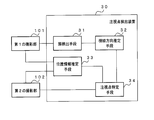
- FIG. 11 is a block diagram showing a main part of the gaze point detecting device according to the present invention.
- the gazing point detection device 30 shown in FIG. 11 acquires the first image and the first depth information acquired by the first photographing unit 101 that acquires the image and the depth information in the range including at least the second photographing unit 102.
- the second image acquired by the second imaging unit 102 which is located so as to face the first imaging unit 101 and acquires the depth information and the image in the range including at least the first imaging unit 101.
- a device for inputting a second depth information which is a face detecting means 31 for detecting a face portion of a target person from a first image and a first depth information (in the embodiment, realized by a face detecting unit 105).
- the line-of-sight direction estimation means 32 (in the embodiment, realized by the line-of-sight direction estimation unit 106) that estimates the line-of-sight direction of the target person using the face portion detected by the face detection means 31. Based on the first image and the first depth information and the second image and the second depth information, the three-dimensional space position of the pupil of the target person and the three-dimensional space of the first shooting unit and the second shooting unit.
- the gaze point of the target person in the embodiment, realized by the position information estimation unit 108) and the three-dimensional spatial position of the pupil of the target person and the line-of-sight direction (the position is realized by the position information estimation unit 108) for estimating the position.
- it includes a gaze point specifying means 34 (in the embodiment, realized by the gaze target estimation unit 108) for specifying the gaze target 2).
- (Appendix 1) Acquiring an image and depth information in a range including at least the second photographing unit The first image and the first depth information acquired by the first photographing unit, and the first photographing unit The second image and the second depth information acquired by the second photographing unit, which are located so as to face each other and acquire at least the image in the range including the first photographing unit and the depth information, are input.
- a face detecting means for detecting a face portion of a target person from the first image and the first depth information
- a line-of-sight direction estimation means that estimates the line-of-sight direction of the target person using the face portion detected by the face detection means, and Based on the first image, the first depth information, the second image, and the second depth information, the three-dimensional spatial position of the pupil of the target person, the first photographing unit, and the first Position information estimating means for estimating the three-dimensional spatial position of the photographing unit of No. 2 and
- a gaze point detecting device including a gaze point specifying means for specifying a gaze point of the target person based on a three-dimensional spatial position of the pupil of the target person and the line-of-sight direction.
- the gazing point specifying means is the gazing point detecting device of the appendix 1 for displaying the gazing point of the target person on an image taken by the second photographing unit.
- the face detecting means acquires an image including the front of the target person as the first image, and the position information estimating means obtains an image including the front of the target person as the first image.
- the gaze point detecting device according to Appendix 1 or Appendix 2, which acquires an image including the back surface of the target person as the second image.
- the position information estimating means calculates a rotation matrix that associates the position of the first photographing unit in the second image with the position of the second photographing unit in the first image.
- a gaze point detecting device according to any one of 1 to 3.
- the position information estimation means is a third image acquired by a third photographing unit installed so as to be able to capture an image in a range including at least the first photographing unit and the second photographing unit. Correct the three-dimensional spatial position of the pupil of the target person and the three-dimensional spatial position of the first photographing unit and the second photographing unit based on the above. Detection device.
- the line-of-sight direction of the target person is estimated, and Based on the first image, the first depth information, the second image, and the second depth information, the three-dimensional spatial position of the pupil of the target person, the first photographing unit, and the first Estimate the 3D spatial position of the imaging unit of 2 and A gaze point detection method for specifying the gaze point of the target person based on the three-dimensional spatial position of the pupil of the target person and the line-of-sight direction.
- Appendix 7 The gazing point detection method of Appendix 6 for displaying the gazing point of the target person on an image captured by the second photographing unit.
- the target person is based on a third image acquired by a third photographing unit installed so as to be able to capture an image in a range including at least the first photographing unit and the second photographing unit.
- Appendix 10 A computer-readable recording medium in which a gazing point detection program is stored.
- the gaze detection program is executed by the processor, Acquiring the image and depth information in the range including at least the second imaging unit
- the first image and the first depth information acquired by the first imaging unit are opposed to the first imaging unit.
- Appendix 11 When the gaze detection program is executed by the processor, The recording medium of Appendix 10 for causing a processor to execute a process of displaying the gazing point of the target person on an image taken by the second photographing unit.
- Appendix 12 When the gaze detection program is executed by the processor, Appendix 10 or Appendix 11 which causes the processor to execute a process of calculating a rotation matrix that associates the position of the first photographing unit in the second image with the position of the second photographing unit in the first image. recoding media.
- Appendix 13 When the gaze detection program is executed by the processor, 3 of the pupil of the target person based on a third image acquired by a third imaging unit installed so as to be able to capture an image in a range including at least the first imaging unit and the second imaging unit.
- the process of estimating the 3D spatial position of the imaging unit of 2 and A gaze point detection program for executing a process of specifying the gaze point of the target person based on the three-dimensional spatial position of the pupil of the target person and the line-of-sight direction.
- Appendix 15 To the computer The gaze point detection program of Appendix 14 for executing a process of displaying the gaze point of the target person on an image taken by the second photographing unit.
- a first photographing means and a second photographing means are provided.
- the first photographing means acquires at least a first image and first depth information in a range including the second photographing means, and obtains the first image and the first depth information.
- the second photographing means is located so as to face the first photographing means, and acquires at least a second image in a range including the first photographing means and a second depth information.
- a face detecting means for detecting a face portion of a target person from the first image and the first depth information
- a line-of-sight direction estimation means that estimates the line-of-sight direction of the target person using the face portion detected by the face detection means, and Based on the first image, the first depth information, the second image, and the second depth information, the three-dimensional spatial position of the pupil of the target person, the first photographing means, and the first
- the position information estimating means for estimating the three-dimensional spatial position of the photographing means of 2 and the A gaze point detection system further comprising a gaze point specifying means for specifying the gaze point of the target person based on the three-dimensional spatial position of the pupil of the target person and the line-of-sight direction.
- the gaze point specifying means is the gaze point detection system of Appendix 18 for displaying the gaze point of the target person on an image taken by the second photographing means.
- the face detecting means acquires an image including the front surface of the target person as the first image, and the position information estimating means obtains an image including the front surface of the target person as the first image.
- the gaze point detection system according to Appendix 18 or Appendix 19, which acquires and acquires an image including the back surface of the target person as the second image.
- the position information estimating means calculates a rotation matrix that associates the position of the first photographing means in the second image with the position of the second photographing means in the first image.
- a gaze point detection system according to any one of 18 to 20.
- a third photographing means installed so as to be able to capture an image in a range including at least the first photographing means and the second photographing means is further provided. Based on the third image acquired by the third photographing means, the position information estimating means includes the three-dimensional spatial position of the pupil of the target person, the first photographing means, and the second photographing means.
- Gaze target estimation unit 1000 CPU 1001 storage device 1002 memory
Landscapes
- Engineering & Computer Science (AREA)
- Theoretical Computer Science (AREA)
- Physics & Mathematics (AREA)
- General Physics & Mathematics (AREA)
- General Engineering & Computer Science (AREA)
- Computer Vision & Pattern Recognition (AREA)
- Human Computer Interaction (AREA)
- Multimedia (AREA)
- Health & Medical Sciences (AREA)
- General Health & Medical Sciences (AREA)
- Oral & Maxillofacial Surgery (AREA)
- Ophthalmology & Optometry (AREA)
- Signal Processing (AREA)
- Image Analysis (AREA)
- Image Processing (AREA)
- Position Input By Displaying (AREA)
- Eye Examination Apparatus (AREA)
Priority Applications (3)
| Application Number | Priority Date | Filing Date | Title |
|---|---|---|---|
| JP2021530421A JP7164047B2 (ja) | 2019-07-10 | 2019-07-10 | 注視点検出装置及び注視点検出方法 |
| PCT/JP2019/027305 WO2021005742A1 (ja) | 2019-07-10 | 2019-07-10 | 注視点検出装置及び注視点検出方法 |
| US17/623,718 US12067162B2 (en) | 2019-07-10 | 2019-07-10 | Gaze point detection device and gaze point detection method |
Applications Claiming Priority (1)
| Application Number | Priority Date | Filing Date | Title |
|---|---|---|---|
| PCT/JP2019/027305 WO2021005742A1 (ja) | 2019-07-10 | 2019-07-10 | 注視点検出装置及び注視点検出方法 |
Publications (1)
| Publication Number | Publication Date |
|---|---|
| WO2021005742A1 true WO2021005742A1 (ja) | 2021-01-14 |
Family
ID=74115021
Family Applications (1)
| Application Number | Title | Priority Date | Filing Date |
|---|---|---|---|
| PCT/JP2019/027305 Ceased WO2021005742A1 (ja) | 2019-07-10 | 2019-07-10 | 注視点検出装置及び注視点検出方法 |
Country Status (3)
| Country | Link |
|---|---|
| US (1) | US12067162B2 (https=) |
| JP (1) | JP7164047B2 (https=) |
| WO (1) | WO2021005742A1 (https=) |
Families Citing this family (6)
| Publication number | Priority date | Publication date | Assignee | Title |
|---|---|---|---|---|
| WO2021005742A1 (ja) * | 2019-07-10 | 2021-01-14 | 日本電気株式会社 | 注視点検出装置及び注視点検出方法 |
| JP7374057B2 (ja) * | 2020-09-16 | 2023-11-06 | 日立Astemo株式会社 | 信号処理装置 |
| US20240277255A1 (en) * | 2023-02-21 | 2024-08-22 | Hillrom Services, Inc. | Systems and methods for monitoring subjects |
| CN117011925B (zh) * | 2023-07-05 | 2026-04-07 | 上海大学 | 一种基于注意力机制和深度先验的注视点检测方法 |
| EP4664244A1 (en) * | 2024-06-13 | 2025-12-17 | Auki Matterless Limited | Determining a gaze location of a human interacting with products in a store |
| WO2026022882A1 (ja) * | 2024-07-22 | 2026-01-29 | 株式会社Nttドコモ | 情報出力制御装置および情報出力制御方法 |
Citations (3)
| Publication number | Priority date | Publication date | Assignee | Title |
|---|---|---|---|---|
| US20130188054A1 (en) * | 2011-07-21 | 2013-07-25 | Lee S. Weinblatt | Monitoring Technique Utilizing an Array of Cameras for Eye Movement Recording |
| JP2015032237A (ja) * | 2013-08-06 | 2015-02-16 | 株式会社京三製作所 | 横断歩道用信号システム |
| JP2017538990A (ja) * | 2014-10-07 | 2017-12-28 | マイクロソフト テクノロジー ライセンシング,エルエルシー | 共有される空間的拡張現実感経験を生成するためのプロジェクターの駆動 |
Family Cites Families (16)
| Publication number | Priority date | Publication date | Assignee | Title |
|---|---|---|---|---|
| JP5477777B2 (ja) | 2010-03-31 | 2014-04-23 | サクサ株式会社 | 画像取得装置 |
| US9514538B2 (en) * | 2012-05-25 | 2016-12-06 | National University Corporation Shizuoka University | Pupil detection method, corneal reflex detection method, facial posture detection method, and pupil tracking method |
| US9137524B2 (en) * | 2012-11-27 | 2015-09-15 | Qualcomm Incorporated | System and method for generating 3-D plenoptic video images |
| EP2995241B1 (en) * | 2013-05-08 | 2021-04-14 | National University Corporation Shizuoka University | Pupil detection light source device, pupil detection device and pupil detection method |
| US9437038B1 (en) * | 2013-09-26 | 2016-09-06 | Amazon Technologies, Inc. | Simulating three-dimensional views using depth relationships among planes of content |
| WO2016164859A1 (en) * | 2015-04-10 | 2016-10-13 | Bespoke, Inc. | Systems and methods for creating eyewear with multi-focal lenses |
| EP3479293A4 (en) * | 2016-06-29 | 2020-03-04 | Seeing Machines Limited | SYSTEMS AND METHODS FOR LOOK TRACKING |
| EP3499462B1 (en) * | 2016-08-12 | 2021-03-10 | National University Corporation Shizuoka University | Line-of-sight detection device |
| US10433725B2 (en) * | 2016-09-15 | 2019-10-08 | The Governors Of The University Of Alberta | System and method for capturing spatially and temporally coherent eye gaze and hand data during performance of a manual task |
| CN109716268B (zh) * | 2016-09-22 | 2022-05-17 | 苹果公司 | 眼部和头部跟踪 |
| US11009715B2 (en) * | 2018-09-12 | 2021-05-18 | Google Llc | Methods and systems for fitting heads-up display to user |
| CN110969061A (zh) * | 2018-09-29 | 2020-04-07 | 北京市商汤科技开发有限公司 | 神经网络训练、视线检测方法和装置及电子设备 |
| US11475592B2 (en) * | 2019-02-12 | 2022-10-18 | Google Llc | Systems and methods for determining an ear saddle point of a user to produce specifications to fit a wearable apparatus to the user's head |
| US10871823B1 (en) * | 2019-05-23 | 2020-12-22 | Facebook Technologies, Llc | Systems and methods for using scene understanding for calibrating eye tracking |
| WO2021005742A1 (ja) * | 2019-07-10 | 2021-01-14 | 日本電気株式会社 | 注視点検出装置及び注視点検出方法 |
| SE2150387A1 (en) * | 2021-03-30 | 2022-10-01 | Tobii Ab | System and method for determining reference gaze data |
-
2019
- 2019-07-10 WO PCT/JP2019/027305 patent/WO2021005742A1/ja not_active Ceased
- 2019-07-10 US US17/623,718 patent/US12067162B2/en active Active
- 2019-07-10 JP JP2021530421A patent/JP7164047B2/ja active Active
Patent Citations (3)
| Publication number | Priority date | Publication date | Assignee | Title |
|---|---|---|---|---|
| US20130188054A1 (en) * | 2011-07-21 | 2013-07-25 | Lee S. Weinblatt | Monitoring Technique Utilizing an Array of Cameras for Eye Movement Recording |
| JP2015032237A (ja) * | 2013-08-06 | 2015-02-16 | 株式会社京三製作所 | 横断歩道用信号システム |
| JP2017538990A (ja) * | 2014-10-07 | 2017-12-28 | マイクロソフト テクノロジー ライセンシング,エルエルシー | 共有される空間的拡張現実感経験を生成するためのプロジェクターの駆動 |
Also Published As
| Publication number | Publication date |
|---|---|
| JPWO2021005742A1 (https=) | 2021-01-14 |
| US12067162B2 (en) | 2024-08-20 |
| JP7164047B2 (ja) | 2022-11-01 |
| US20220244779A1 (en) | 2022-08-04 |
Similar Documents
| Publication | Publication Date | Title |
|---|---|---|
| JP7164047B2 (ja) | 注視点検出装置及び注視点検出方法 | |
| US10129490B2 (en) | Systems and approaches for thermal image corrections | |
| US10839544B2 (en) | Information processing apparatus, information processing method, and non-transitory computer readable storage medium | |
| US11715236B2 (en) | Method and system for re-projecting and combining sensor data for visualization | |
| JP7224832B2 (ja) | 情報処理装置、情報処理方法、及びプログラム | |
| JP7250443B2 (ja) | 画像処理装置 | |
| TWI581007B (zh) | 頭戴型顯示裝置及其校正方法 | |
| US20140368615A1 (en) | Sensor fusion for depth estimation | |
| JP7420135B2 (ja) | 情報処理装置、情報処理方法、及びプログラム | |
| JP5853141B2 (ja) | 人数計測装置、人数計測システムおよび人数計測方法 | |
| US20190026919A1 (en) | Information processing apparatus, information processing method, and program | |
| WO2012012555A1 (en) | Methods and systems for audience digital monitoring | |
| CA2564262A1 (en) | Apparatus and method for detecting a pointer relative to a touch surface | |
| US20150332506A1 (en) | Information processing apparatus and information processing method | |
| US10460466B2 (en) | Line-of-sight measurement system, line-of-sight measurement method and program thereof | |
| US10481680B2 (en) | Systems and methods to provide a shared augmented reality experience | |
| EP3667462B1 (en) | Screen position estimation | |
| JP5727969B2 (ja) | 位置推定装置、方法、及びプログラム | |
| US12238422B2 (en) | Method of constructing front panorama of shelving from arbitrary series of frames based on shelving 3D model | |
| WO2017163283A1 (ja) | 監視装置及び監視システム | |
| WO2020158035A1 (ja) | 物体位置推定装置およびその方法 | |
| US20200388078A1 (en) | Apparatus for positioning processing between image in real world and image in virtual world, information processing method, and storage medium | |
| CN112532874A (zh) | 生成平面热力图的方法、装置、存储介质和电子设备 | |
| CN112073640A (zh) | 全景信息采集位姿获取方法及装置、系统 | |
| JP7040627B2 (ja) | 算出装置、情報処理方法およびプログラム |
Legal Events
| Date | Code | Title | Description |
|---|---|---|---|
| 121 | Ep: the epo has been informed by wipo that ep was designated in this application |
Ref document number: 19936692 Country of ref document: EP Kind code of ref document: A1 |
|
| ENP | Entry into the national phase |
Ref document number: 2021530421 Country of ref document: JP Kind code of ref document: A |
|
| NENP | Non-entry into the national phase |
Ref country code: DE |
|
| 122 | Ep: pct application non-entry in european phase |
Ref document number: 19936692 Country of ref document: EP Kind code of ref document: A1 |