WO2020262462A1 - Outer packaging member for vacuum heat-insulating member, vacuum heat-insulating member, and article provided with vacuum heat-insulating member - Google Patents
Outer packaging member for vacuum heat-insulating member, vacuum heat-insulating member, and article provided with vacuum heat-insulating member Download PDFInfo
- Publication number
- WO2020262462A1 WO2020262462A1 PCT/JP2020/024838 JP2020024838W WO2020262462A1 WO 2020262462 A1 WO2020262462 A1 WO 2020262462A1 JP 2020024838 W JP2020024838 W JP 2020024838W WO 2020262462 A1 WO2020262462 A1 WO 2020262462A1
- Authority
- WO
- WIPO (PCT)
- Prior art keywords
- layer
- vacuum heat
- heat insulating
- inorganic
- outer packaging
- Prior art date
Links
Images


Classifications
-
- B—PERFORMING OPERATIONS; TRANSPORTING
- B32—LAYERED PRODUCTS
- B32B—LAYERED PRODUCTS, i.e. PRODUCTS BUILT-UP OF STRATA OF FLAT OR NON-FLAT, e.g. CELLULAR OR HONEYCOMB, FORM
- B32B9/00—Layered products comprising a layer of a particular substance not covered by groups B32B11/00 - B32B29/00
-
- F—MECHANICAL ENGINEERING; LIGHTING; HEATING; WEAPONS; BLASTING
- F16—ENGINEERING ELEMENTS AND UNITS; GENERAL MEASURES FOR PRODUCING AND MAINTAINING EFFECTIVE FUNCTIONING OF MACHINES OR INSTALLATIONS; THERMAL INSULATION IN GENERAL
- F16L—PIPES; JOINTS OR FITTINGS FOR PIPES; SUPPORTS FOR PIPES, CABLES OR PROTECTIVE TUBING; MEANS FOR THERMAL INSULATION IN GENERAL
- F16L59/00—Thermal insulation in general
- F16L59/06—Arrangements using an air layer or vacuum
- F16L59/065—Arrangements using an air layer or vacuum using vacuum
Definitions
- the present disclosure relates to an outer packaging material for a vacuum heat insulating material, a vacuum heat insulating material, and an article with the vacuum heat insulating material capable of forming the vacuum heat insulating material.
- the vacuum heat insulating material is a member in which the core material is arranged inside the bag of the outer packaging material and the inside of the bag is held in a vacuum state where the pressure is lower than the atmospheric pressure, and the internal heat convection is suppressed, which is good. Can demonstrate excellent heat insulation performance.
- the outer packaging material used for the vacuum heat insulating material will be described as an outer packaging material for the vacuum heat insulating material, or simply an outer packaging material.
- the outer packaging material for the vacuum heat insulating material has gas barrier performance to suppress the permeation of gas such as oxygen and steam in order to maintain the vacuum state inside the vacuum heat insulating material for a long period of time, and the ends are joined when wrapping the core material. Therefore, physical properties such as heat-welding property for sealing and sealing the core material are required.
- the outer packaging material for the vacuum heat insulating material is generally configured to include a gas barrier film and a heat-weldable film as members.
- Patent Document 1 describes an outer packaging material using an aluminum foil
- Patent Document 2 discloses a vapor-deposited film in which an aluminum vapor-deposited layer is formed on a polyvinyl alcohol-based polymer film as an outer packaging material.
- vacuum heat insulating materials that can transmit radio waves are required for the purpose of identification and traceability of contents.
- the outer packaging material used for the conventional vacuum heat insulating material generally contains a metal foil or a metal vapor deposition layer, there is a problem that it blocks radio waves and is not suitable for applications requiring wireless communication inside and outside the space. It was.
- the present disclosure is an invention made in view of the above problems, an outer packaging material for a vacuum heat insulating material capable of producing a vacuum heat insulating material capable of transmitting radio waves and maintaining good heat insulating performance, and a vacuum using the same.
- the main purpose is to provide the heat insulating material and the article with the vacuum heat insulating material.
- the present disclosure is an outer packaging material for a vacuum heat insulating material having a heat-weldable film and two or more inorganic layers including a first inorganic layer and a second inorganic layer. Further, the first inorganic layer, the inorganic layered compound layer, and the second inorganic layer are arranged in this order, including the inorganic layered compound layer containing the inorganic layered compound and the binder resin, and the metal layer is formed. Provided an outer packaging material for vacuum insulation which is not arranged.
- the present disclosure provides a vacuum heat insulating material having a core material and an outer packaging material in which the core material is enclosed, wherein the outer packaging material is the above-mentioned vacuum heat insulating outer packaging material. ..
- the present disclosure is an article having a heat insulating region and an article with a vacuum heat insulating material provided with the vacuum heat insulating material, and the vacuum heat insulating material has a core material and an outer packaging material in which the core material is enclosed.
- the outer packaging material is the above-mentioned vacuum heat insulating outer packaging material.
- an outer packaging material for a vacuum heat insulating material capable of producing a vacuum heat insulating material capable of transmitting radio waves and maintaining good heat insulating performance.
- the present disclosure includes an outer packaging material for a vacuum heat insulating material, a vacuum heat insulating material, and an article with the vacuum heat insulating material in embodiments.
- an outer packaging material for a vacuum heat insulating material, a vacuum heat insulating material, and an article with the vacuum heat insulating material in embodiments.
- embodiments of the present disclosure will be described with reference to drawings and the like.
- the present disclosure can be implemented in many different embodiments and is not construed as limited to the description of the embodiments exemplified below.
- the drawings may schematically represent the width, thickness, shape, etc. of each part as compared with the embodiment, but this is merely an example and the interpretation of the present disclosure is limited. It's not something to do.
- a certain structure such as a certain member or a certain area is "above (or below)" another structure such as another member or another area.
- this includes not only the case of being directly above (or directly below) the other configuration, but also the case of being above (or below) the other configuration, that is, separately above (or below) the other configuration. Including the case where the component of is included.
- the present inventors considered using a metal oxide-deposited layer instead of a metal layer for the gas barrier film in order to make the outer packaging material for the vacuum heat insulating material transparent to radio waves. It was found that the performance was insufficient. Therefore, in order to improve the gas barrier performance, an attempt was made to increase the number of metal oxide layers to be laminated and to thicken the metal oxide layer per layer. However, it has been found that when the number of metal oxide layers is increased, the productivity is low, the flexibility as the exterior material is lost, and the barrier is easily broken when various bendings are applied. Further, it has been found that when the metal oxide layer per layer is thickened, it is not easy to improve the barrier performance because the barrier film is cracked even if the film is thickened in the first place.
- the water vapor barrier performance and the oxygen barrier performance of the outer packaging material for the vacuum heat insulating material are lowered, but the water vapor barrier performance is lowered and the amount of water vapor flowing into the vacuum heat insulating material is increased. It is possible to suppress the increase in the internal vacuum degree and reduce the influence on the heat insulating performance of the vacuum heat insulating material only by adding an inexpensive desiccant together with the core material to the vacuum heat insulating material. it can. Therefore, as for the performance of the outer packaging material for the vacuum heat insulating material, the lowering of the oxygen barrier performance is more problematic for maintaining the heat insulating performance of the vacuum heat insulating material than the lowering of the water vapor barrier performance.
- the present inventors have arranged an oxygen barrier by arranging a layer containing an inorganic layered compound instead of arranging a metal layer on the outer packaging material for the vacuum heat insulating material.
- a layer containing an inorganic layered compound instead of arranging a metal layer on the outer packaging material for the vacuum heat insulating material.
- it is possible to suppress the deterioration of oxygen barrier performance by ensuring the performance and further sandwiching the layer containing the inorganic layered compound between the inorganic layers, and it is possible to transmit radio waves and provide good heat insulation performance.
- it is an outer packaging material for vacuum heat insulating materials that can produce a sustainable vacuum heat insulating material.
- the outer packaging material for the vacuum heat insulating material, the vacuum heat insulating material, and the article with the vacuum heat insulating material of the present disclosure will be described.
- the outer packaging material for a vacuum heat insulating material of the present disclosure is an outer packaging material for a vacuum heat insulating material having a heat-weldable film and two or more inorganic layers including a first inorganic layer and a second inorganic layer.
- the outer packaging material for a vacuum heat insulating material further includes an inorganic layered compound layer containing an inorganic layered compound and a binder resin, and the first inorganic layer, the inorganic layered compound layer, and the second inorganic layer are the same. It is characterized in that it is arranged in order and no metal layer is arranged.
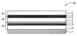
- FIG. 1 is a schematic cross-sectional view showing an example of the outer packaging material for the vacuum heat insulating material of the present disclosure.
- the vacuum heat insulating material outer packaging material 10 of the present disclosure is first from the heat-weldable film 1 arranged on one main surface side of the vacuum heat insulating material outer packaging material 10 and the heat-weldable film 1 side. It is characterized by including each layer arranged in the order of the inorganic layer 4, the inorganic layered compound layer 5 containing the inorganic layered compound and the binder resin, and the second inorganic layer 4.
- the vacuum heat insulating material outer packaging material 10 has a first gas barrier film 2a, a second gas barrier film 2b, and a third gas barrier film 2c, and each gas barrier film has an inorganic layer 4 respectively.
- the first gas barrier film 2a contains the first inorganic layer 4
- the second gas barrier film 2b contains the second inorganic layer 4.
- the inorganic layered compound layer 5 is contained in the first gas barrier film 2a.
- the first gas barrier film 2a includes a first resin base material 3 and an inorganic layer 4 (first inorganic layer 4) arranged on one main surface side of the first resin base material 3.
- the second gas barrier film 2b has an inorganic layer 4 (second inorganic layer 4) arranged on at least one main surface side of the second resin base material 3 and the second resin base material 3.
- the inorganic layered compound layer 5 in the first gas barrier film is arranged between the first inorganic layer 4 in the first gas barrier film 2a and the second inorganic layer 4 in the second gas barrier film 2b.
- the third gas barrier film 2c having the third resin base material 3 and the third inorganic layer 4 on the opposite side of the second gas barrier film 2b from the first gas barrier film 2a is formed by the third inorganic layer 4. Is arranged so as to be on the side of the second gas barrier film 2b.
- the outer packaging material for the vacuum heat insulating material of the present disclosure is characterized in that no metal layer is arranged.
- the metal layer is a metal layer in which metal atoms constituting the metal atom are bonded to each other by a metal bond and have radio wave blocking property.
- the metal layer include metal foils such as aluminum, nickel, stainless steel, iron, copper, and titanium, and metal thin films.
- the outer packaging material for the vacuum heat insulating material of the present disclosure does not have a metal layer arranged, radio waves can be transmitted. Further, by having the inorganic layered compound layer instead of the metal layer, the inorganic layers are arranged on both sides of the inorganic layered compound layer while ensuring the oxygen barrier property, and the inorganic layered compound layer is sandwiched between the inorganic layers. Therefore, deterioration of the oxygen barrier performance of the inorganic layered compound layer can be suppressed. Therefore, it is an external packaging material for a vacuum heat insulating material that can transmit radio waves and can manufacture a vacuum heat insulating material that can maintain good heat insulating performance.
- the outer packaging material for vacuum heat insulating material of the present disclosure has two or more inorganic layers including a first inorganic layer and a second inorganic layer, and the inorganic layered compound layer is the first inorganic layer and the second inorganic layer. It is characterized by having a structure arranged between layers.
- the inorganic layer is a layer other than the metal layer such as a metal foil or a metal thin film, and is an inorganic compound film or an MOP bond (where M indicates a metal atom, O indicates an oxygen atom, and P is an oxygen atom.
- the inorganic layer is preferably an inorganic compound film, particularly a metal oxide film.
- Examples of the inorganic compound constituting the inorganic compound film include oxides of metal elements or non-metal elements such as silicon, aluminum, magnesium, calcium, potassium, tin, sodium, titanium, boron, yttrium, zirconium, cerium, and zinc. Examples thereof include oxidative nitrides, nitrides, oxidative carbides, and oxidative carbides. Specifically, silicon oxides such as SiO 2 , aluminum oxides such as Al 2 O 3 , magnesium oxides, titanium oxides, tin oxides, silicon zinc alloy oxides, indium alloy oxides, and silicon nitrides. Examples thereof include aluminum nitride, titanium nitride, silicon oxide and zinc oxide. In particular, metal oxides, especially aluminum oxide (alumina) and silicon oxide (silica) are preferable.
- the inorganic compound may be used alone or may be used by mixing the above-mentioned materials in an arbitrary ratio.
- the inorganic compound film may be a thin-film film formed by a thin-film deposition method or a coat film formed by a coating method such as coating. In the case of a thin-film deposition film, it may be formed by single-film deposition or the like, or may be formed by multiple-time vapor deposition.
- the inorganic compound film can be formed by a conventionally known method such as a coating method, a vapor deposition method, or a pressure bonding method.
- a thin-film deposition film is preferable from the viewpoint of having high adhesion to a resin base material and exhibiting high gas barrier performance.
- One gas barrier film may be a single film formed by single vapor deposition, or may be formed by multiple vapor deposition and have a laminated structure.
- reaction products of metal oxides and phosphorus compounds can be used.
- examples include membranes containing.
- metal oxide examples include oxides of metals having a valence of 2 or more.
- metals of Group 2 of the periodic table such as magnesium and calcium; Group 12 of the periodic table such as zinc.
- aluminum oxide (alumina) is preferable.
- Examples of the phosphorus compound include phosphoric acid, polyphosphoric acid, phosphorous acid, phosphonic acid and derivatives thereof. Of these, phosphoric acid is preferable.
- the specific reaction products of the metal oxide and the phosphorus compound can be, for example, the same as the reaction products disclosed in JP-A-2011-226644.
- the presence of MOP bonds causes the maximum infrared absorption peak to appear within the range of 1080 cm -1 or more and 1130 cm -1 or less in the infrared absorption spectrum (measured wavenumber range; 800 cm -1 or more and 1400 cm -1 or less). You can check it by doing.
- the method for measuring the infrared absorption spectrum is not particularly limited, and for example, a measurement method by the total reflection measurement method (ATR method), a method of scraping a sample from the gas barrier film of the outer packaging material, and measuring the infrared absorption spectrum by the KBr method.
- a measurement method or the like can be used for the collected sample by microinfrared spectroscopy.
- the thickness of the inorganic layer is not particularly limited, but is preferably 50 nm or less. By setting the thickness of the inorganic layer to the above value or less, sufficient flexibility can be maintained and barrier fracture is less likely to occur.
- composition and thickness of the two or more inorganic layers contained in the outer packaging material for the vacuum heat insulating material of the present disclosure may be the same or different.
- the inorganic layered compound layer in the present disclosure is a layer arranged between a first inorganic layer and a second inorganic layer. As long as the inorganic layered compound layer is arranged between the first inorganic layer and the second inorganic layer, its arrangement position is not particularly limited, and one main surface of the resin base material or one of the inorganic layers Can be provided on the main surface of.
- the inorganic layered compound layer contains at least an inorganic layered compound and a binder resin.
- Such an inorganic layered compound layer is different from one in which gas permeation is prevented by a continuous film such as a thin-film vapor deposition thin film, and innumerable inorganic layered compounds dispersed in the layer block the progress of gas and bypass it (maze). (Effect), it extends the path required for permeation and exerts barrier performance. Since the gas mainly travels in the binder resin in the inorganic layered compound layer, the gas barrier performance of the binder resin itself is important for exhibiting high barrier performance, but the gas barrier performance of the binder resin is lowered by water vapor. There is.
- the inorganic layered compound layer has a structure located between the first inorganic layer and the second inorganic layer, and each layer constituting the water vapor entering from the outside air and the outer packaging material for the vacuum heat insulating material is inside.
- the influence of the water vapor contained can be reduced. Therefore, in particular, in a configuration in which the inorganic layered compound layer is directly sandwiched between the first inorganic layer and the second inorganic layer, for example, the resin base material does not come into direct contact with the inorganic layered compound layer, so that the resin group It is possible to suppress deterioration of the gas barrier performance of the binder resin due to water vapor contained in the material.
- a layer other than the adhesive layer and the overcoat layer that is, a resin
- the base material, etc. is not arranged.
- the inorganic layered compound means an inorganic compound having a layered structure in which unit crystal layers are stacked on each other. That is, the "layered compound” means a compound or substance having a layered structure. Further, the “layered structure” refers to a structure in which atoms are strongly bonded by a covalent bond or the like and closely arranged surfaces are stacked in parallel by a weak bonding force such as a van der Waals force.
- the inorganic layered compound may be any compound having a layered structure, and examples thereof include graphite, phosphate-based derivative compounds (zoxide-based compounds), chalcogenides, and clay minerals. Of these, clay minerals are preferable.
- clay minerals phyllosilicate minerals such as hydrous silicates; kaolinite group clay minerals such as halloysite, kaolinite, enderite, deckite, and nacrite; antigolite group clays such as antigolite and chrysotile.
- Smectite clay minerals such as montmorillonite, iron montmorillonite, byderite, nontronite, saponite, hectrite, soconite, and stibuncite
- vermiculite clay minerals such as vermiculite
- mica such as white mica and gold mica
- margarite, tetrasi Mica or mica clay minerals such as lyric mica and teniolite
- green mudstone clay minerals such as cuckeyite, sudowite, clinochloa, chamosite and nimate, or substitutions and derivatives thereof.
- These clay minerals may be natural clay minerals or synthetic clay minerals, and may contain two or more kinds in combination.
- phyllosilicate minerals and smectite group clay minerals are preferable, and montmorillonite and hectorite contained in smectite group clay minerals are particularly preferable.
- the average particle size of the particles of the inorganic layered compound is preferably 50 nm or more and 5 ⁇ m or less, particularly preferably 100 nm or more and 4 ⁇ m or less, and particularly preferably 500 nm or more and 3 ⁇ m or less. This is because the oxygen barrier performance of the inorganic layered compound layer becomes better by setting the average particle size of the particles of the inorganic layered compound in the above range.
- the particle size of the particles of the inorganic layered compound is the center diameter (major axis) obtained from the photon correlation method by the dynamic light scattering method measured using an ultrafine particle size analyzer under the conditions of a temperature of 25 ° C. and an aqueous solvent. ..
- the aspect ratio of the inorganic layered compound is preferably 50 or more and 5000 or less, particularly preferably 200 or more and 3000 or less, and particularly preferably 300 or more and 2500 or less. This is because the oxygen barrier performance of the inorganic layered compound layer becomes better by setting the aspect ratio of the inorganic layered compound in the above range.
- the aspect ratio of the inorganic layered compound is the ratio of the average interplanar spacing (average unit thickness) to the average particle size of the particles of the inorganic layered compound, and is calculated by the following formula (1).
- Z L / a ... (1) (In the above formula (1), Z is the aspect ratio, L is the average particle size of the inorganic layered compound, and a is the average interplanar spacing (average unit thickness) of the inorganic layered compound.)
- the average particle size L of the inorganic layered compound is a value obtained by the method described above.
- the surface spacing (unit thickness) a of the inorganic layered compound is, for example, a value obtained by powder X-ray diffraction measurement of the inorganic layered compound using an X-ray diffractometer. From the powder X-ray diffraction measurement of the composition containing the inorganic layered compound and the binder resin, it can be confirmed that there is a portion where the surface spacing of the inorganic layered compound is widened.
- the binder resin is not particularly limited, but a hydrophilic resin containing a hydrophilic group is preferable. This is because the hydrophilic resin exhibits a high barrier property against oxygen.
- a hydrophilic resin containing a hydrophilic group is preferable. This is because the hydrophilic resin exhibits a high barrier property against oxygen.
- polyvinyl alcohol and polyacrylic acid are particularly preferable
- the hydrophilic resin tends to deteriorate its gas barrier performance due to water vapor, but the packaging material for the vacuum heat insulating material of the present disclosure has a structure in which a layered compound layer is sandwiched between a first inorganic layer and a second inorganic layer. Therefore, it is possible to suppress the deterioration of the hydrophilic resin for the reason described above, and it is possible to maintain a high barrier property against oxygen of the inorganic layered compound layer.
- the volume ratio of the inorganic layered compound to the binder resin is preferably 5/95 to 90/10, and more preferably 5/95 to 50/50. preferable. This is because the inorganic layered compound layer having excellent oxygen barrier performance and bending resistance can be obtained by setting the volume ratio of the inorganic layered compound to the binder resin in the above range.
- the thickness of the inorganic layered compound layer is preferably 1 ⁇ m or less, particularly preferably 50 nm or more and 500 nm or less, and particularly preferably 100 nm or more and 300 nm or less.
- a heat-weldable layer is arranged on one main surface side.
- Such a heat-weldable film is a film that can be welded by heating.
- the heat-weldable film is a member that bears one surface in the thickness direction of the vacuum heat insulating material outer packaging material, and is used as a core material when the vacuum heat insulating material outer packaging material of the present disclosure is used to produce the vacuum heat insulating material. It is a member that joins the ends of the outer packaging materials for vacuum heat insulating materials that are in contact with each other and that are opposed to each other when sealing the core material.
- a resin film that can be melted and fused by heating can be used.
- polyethylene such as linear short-chain branched polyethylene (LLDPE) and unstretched polypropylene (CPP) can be used.
- LLDPE linear short-chain branched polyethylene
- CPP unstretched polypropylene
- PET polyethylene terephthalate
- PEN polyethylene naphthalate
- PBT polybutylene terephthalate
- other polyester resin films polyvinyl acetate resin films
- polyvinyl chloride resin films poly ( Meta) Acrylic resin film; Urethane resin film and the like can be mentioned.
- the heat-weldable film may contain other materials such as an anti-blocking agent, a lubricant, a flame retardant, and a filler.
- the thickness of the heat-weldable film may be any thickness as long as it can obtain a desired adhesive force when the outer packaging materials for vacuum heat insulating materials are joined to each other. For example, it is in the range of 15 ⁇ m or more and 100 ⁇ m or less, preferably 25 ⁇ m. It can be within the range of 90 ⁇ m or more, more preferably 30 ⁇ m or more and 80 ⁇ m or less.
- Resin base material The outer packaging material for the vacuum heat insulating material of the present disclosure is not particularly limited, but the above-mentioned inorganic layer or inorganic layered compound layer can usually be provided on one main surface of the resin base material. ..
- a resin base material for example, a resin film or the like is preferably used.
- the resin base material is a resin film
- the resin film may be unstretched or may be uniaxially or biaxially stretched.
- the resin base material may or may not have transparency.
- the resin used for the resin base material is not particularly limited, and is, for example, a polyolefin resin such as polyethylene or polypropylene, a polyester resin such as polyethylene terephthalate (PET), polyethylene naphthalate (PEN), or polybutylene terephthalate (PBT).
- a polyolefin resin such as polyethylene or polypropylene
- a polyester resin such as polyethylene terephthalate (PET), polyethylene naphthalate (PEN), or polybutylene terephthalate (PBT).
- Cyclic polyolefin resin polystyrene resin, acrylonitrile-styrene copolymer (AS resin), acrylonitrile-butadiene-styrene copolymer (ABS resin), poly (meth) acrylic resin, polycarbonate resin, ethylene-vinyl ester copolymer and Various resins such as the saponified product, various polyamide resins such as nylon, polyimide resin, polyurethane resin, acetal resin, and cellulose resin can be used. Among the above resins, PET, PBT, nylon and the like are more preferably used.
- the resin base material may contain various plastic compounding agents, additives and the like.
- the additive include a lubricant, a cross-linking agent, an antioxidant, an ultraviolet absorber, a light stabilizer, a filler, a reinforcing agent, an antistatic agent, a pigment, a resin for modification and the like.
- the resin base material may be surface-treated. This is because the adhesion with the inorganic layer can be improved.
- the surface treatment include an oxidation treatment, a roughening treatment (roughening treatment), and an easy-adhesion coating treatment disclosed in Japanese Patent Application Laid-Open No. 2014-180837.
- the thickness of the resin base material is not particularly limited, but is, for example, in the range of 6 ⁇ m to 200 ⁇ m, more preferably 9 ⁇ m to 100 ⁇ m (in the present specification, the designations A to B indicate a range including A and B). It is.).
- the resin base material may be a single layer or a multilayer body in which a plurality of resin layers are laminated. In the multilayer body, each resin layer may be composed of different resins or may be composed of the same resin.
- the resin base material described above is not arranged between the inorganic layered compound layer and the first inorganic layer or the second inorganic layer.
- the resin base material described above is not arranged between the inorganic layered compound layer and the first inorganic layer or the second inorganic layer.
- the overcoat layer can be arranged on one main surface of the inorganic layer or one main surface of the inorganic layered compound layer. By providing the overcoat layer, it is possible to impart more excellent gas barrier properties to the outer packaging material for the vacuum heat insulating material.
- Such an overcoat layer contains a hydrophilic group-containing resin.
- the presence or absence of the hydrophilic group-containing resin can be determined by, for example, an infrared absorption spectrum.
- the ratio of metal atoms to carbon atoms (number of metal atoms / number of carbon atoms) in the atoms constituting the overcoat layer is in the range of 0.1 or more and 2 or less, and among them, 0.5 or more and 1 It is preferably in the range of 9.9 or less, particularly in the range of 0.8 or more and 1.6 or less. If the ratio is less than the above range, the brittleness of the overcoat layer becomes large, and the water resistance and weather resistance of the obtained overcoat layer may decrease. On the other hand, if the ratio exceeds the above range, the gas barrier property of the obtained overcoat layer may decrease.
- the content of the hydrophilic group-containing resin in the composition for forming the overcoat layer is 5 parts by mass or more, 500 parts by mass with respect to 100 parts by mass of the total amount of alkoxide described later. It can be obtained by setting the blending ratio within the range of 20 parts by mass or more and 200 parts by mass or less.
- solution A a mixed solution consisting of polyvinyl alcohol (PVA), isopropyl alcohol and ion-exchanged water
- solution B tetraethoxysilane (TEOS), isopropyl alcohol
- Hydrolyzed solution consisting of hydrochloric acid and ion-exchanged water
- a specific ratio of PVA to 100 parts by mass of TEOS and stirred to obtain a colorless and transparent overcoat layer forming composition obtained by a sol-gel method.
- the film thickness of the overcoat layer is not particularly limited, but is preferably 200 nm or more. This is because if it is equal to or more than the above value, the gas barrier property of the outer packaging material for the vacuum heat insulating material can be surely improved.
- an overcoat layer may be arranged particularly between the inorganic layered compound layer and the second inorganic layer. By arranging the overcoat layer, pinholes and the like existing in the inorganic layer can be filled, so that it is possible to further prevent the invasion of water vapor. However, what is a heat-weldable film of the inorganic layered compound layer? This is because by arranging the overcoat layer with respect to the second inorganic layer arranged on the opposite side, it is possible to suppress the permeation of water vapor from the outside where water vapor easily penetrates.
- Adhesive layer The outer packaging material for vacuum heat insulating material of the present disclosure may have an adhesive layer between each barrier film or a heat-weldable layer.
- adhesive layer conventionally known pressure-sensitive adhesives, thermoplastic adhesives, curable adhesives and the like can be used.
- the adhesive constituting the adhesive layer is usually a two-component curable adhesive containing a main agent and a curing agent, but the adhesive is not limited thereto.
- It may be a one-component curable adhesive in which a latent main agent blocked by the method and a curing agent are mixed.
- the adhesive constituting the adhesive layer include an epoxy adhesive, a polyvinyl acetate adhesive, a polyacrylic acid ester adhesive, a cyanoacrylate adhesive, an ethylene copolymer adhesive, and cellulose.
- Adhesives polyester adhesives, polyamide adhesives, polyimide adhesives, amino resin adhesives, phenol resin adhesives, polyurethane adhesives, reactive (meth) acrylic acid adhesives, inorganic rubber adhesives
- Adhesives, silicone-based adhesives, inorganic adhesives made of alkali metal silicate, low-melting point glass, etc. can be used.
- the adhesive a polyacrylic acid ester adhesive, a polyurethane adhesive and the like are preferable, and in particular, the adhesive is preferably a compound having an isocyanate group as a functional group, and specifically, a polyurethane adhesive. It is preferably an adhesive.
- the adhesive constituting the adhesive layer may contain any material such as a curing accelerator, a catalyst, an antioxidant, a stabilizer, an ultraviolet absorber, a light stabilizer, and an antistatic agent.
- the thickness of the adhesive layer may be any thickness as long as it can exhibit a desired adhesive force, and can be appropriately set according to the composition of the adhesive layer and the like. Usually, it is preferable that the thickness of which becomes 0.1g / m 2 ⁇ 10g / m 2 approximately in a dry state.
- the adhesive layer may or may not have transparency, but when transparency is required as the outer packaging material for the vacuum heat insulating material, it is preferable that the adhesive layer has transparency.
- a sheet or film formed by the above-mentioned adhesive may be used, and a coating liquid prepared by mixing the above-mentioned adhesive with a desired solvent is prepared, and one surface of a heat-welable film or a gas barrier film is prepared. It may be applied directly to, dried and cured to form.
- the adhesive layer described above may be arranged between the inorganic layered compound layer and the first inorganic layer or the second inorganic layer.
- each gas barrier film which is a film having gas barrier performance and constitutes the outer packaging material for the vacuum heat insulating material of the present disclosure.
- the two or more inorganic layers and the inorganic layered compound layer may be present in different gas barrier films, but a plurality of layers (for example, the first inorganic layer and the inorganic layered compound) are present in one gas barrier film. Layer) may be present.
- the inorganic layered compound layer 5 in the first gas barrier film 2a is composed of the first inorganic layer 4 in the first gas barrier film 2a and the second inorganic layer 4 in the second gas barrier film 2b. Arranged between them, the first inorganic layer 4, the inorganic layered compound layer 5, and the second inorganic layer 4 are contained in the outer packaging material 10 for vacuum heat insulating material in this order, and the second gas barrier film 2b The second inorganic layer 4 in the above is arranged so as to face the inorganic layered compound layer 5 of the first gas barrier film 2a.
- such a first embodiment includes the following two aspects.
- a heat-weldable film, a first resin base material, a first inorganic layer, an inorganic layered compound layer, a second inorganic layer, and a second resin layer are arranged in this order. It is an arranged aspect.
- the third inorganic layer and the third resin base material are placed on the surface of the second resin base material opposite to the second inorganic layer. It is an aspect arranged in order.
- the first gas barrier film in this embodiment is arranged on one main surface side of the heat-weldable film, and is arranged between the heat-weldable film and the second gas barrier film. It is a thing.
- the first gas barrier film has at least a first resin base material, a first inorganic layer, and an inorganic layered compound layer, and the inorganic layered compound layer is a second inorganic layer of the second gas barrier film. It is arranged so as to face the.
- it is preferable that no other gas barrier film or protective film is arranged between the first gas barrier film and the heat-weldable film.
- the first resin substrate is usually arranged so as to face the heat-weldable film.
- the first resin base material is not particularly limited as long as it can support the first inorganic layer described later. Specifically, the same as those exemplified in “5. Resin base material” can be mentioned. Examples of the first inorganic layer and the inorganic layered compound layer are the same as those exemplified in "1. Inorganic layer” and “2. Inorganic layered compound layer", respectively.
- the second gas barrier film in the present embodiment is arranged on the main surface side opposite to the heat-weldable film of the first gas barrier film, and has a second resin base material and a second gas barrier film. It has an inorganic layer, and the second inorganic layer is arranged so as to face the inorganic layered compound layer of the first gas barrier film.
- Examples of the second resin base material include those similar to those exemplified in “5. Resin base material” described above.
- Examples of the second inorganic layer include those similar to those exemplified in "1. Inorganic layer”.
- the second gas barrier film may have an overcoat layer on the main surface of the second inorganic layer opposite to the second resin base material.
- the inorganic layered compound layer in the first gas barrier film is arranged so as to face the second inorganic layer in the second gas barrier film, so that the inorganic layered compound layer and the second inorganic layer are separated from each other.
- adhesion is made between the heat-weldable film and the first gas barrier film, between the first gas barrier film and the second gas barrier film, between the second gas barrier film and the third gas barrier film, and the like.
- Layers can be located. Examples of the adhesive layer include those similar to those exemplified in "6. Adhesive layer" described above.
- the outer packaging material for the vacuum heat insulating material of the present embodiment has at least a first gas barrier film and a second gas barrier film, but it is preferable to have at least one layer or more of the gas barrier film.
- the outer packaging material for the vacuum heat insulating material of the present disclosure preferably has three layers of gas barrier films, and specifically, as shown in FIG. 1, the first gas barrier film 2a and the second gas barrier film 2b In addition, it is preferable to have a third gas barrier film 2c. This is because the gas barrier property can be improved by having the gas barrier film having three layers in this way.
- the gas barrier film may be provided with four or more layers, but if the layer structure is increased, the productivity may be low and the flexibility may be lowered.
- the third gas barrier film is not particularly limited as long as it is a layer that does not contain a metal layer, and is typically a third gas barrier film arranged on one main surface side of the third resin base material and the third resin base material. It has 3 inorganic layers. Examples of the third resin base material and the third inorganic layer include those similar to those exemplified in "5. Resin base material" and "1. Inorganic layer" described above.
- the third inorganic layer an inorganic compound film made of aluminum oxide (alumina) and silicon oxide (silica) is preferable.
- the thickness of the third inorganic layer is not particularly limited, but is preferably 50 nm or less. By setting the thickness of the third inorganic layer to the above value or less, the flexibility can be sufficiently maintained and the barrier fracture is less likely to occur.
- the second gas barrier film and the third gas barrier film included in the outer packaging material for the vacuum heat insulating material of the present disclosure may be the same, and the type, layer structure, material and the like may be different.
- the position of the third inorganic layer in the third gas barrier film is not particularly limited, but usually, the third inorganic layer is arranged so as to be closer to the second gas barrier film than the third resin base material.
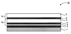
- the outer packaging material of the second embodiment as illustrated in FIG. 3 is also preferable.
- the resin base material 3 of the second gas barrier film 2b in the outer packaging material of the first embodiment shown in FIG. 1 faces the inorganic layered compound layer 5 of the first gas barrier film 2a. It is the same as the first embodiment except that it is arranged in such a manner. That is, in this embodiment, at least the second resin base material 3 is interposed between the inorganic layered compound layer 5 in the first gas barrier film and the second inorganic layer 4 in the second gas barrier film 2b. From the heat-weldable film 1 side, the first inorganic layer 4, the inorganic layered compound layer 5, the resin base material 3, and the second inorganic layer 4 are contained in the outer packaging material 10 for vacuum heat insulating material in this order. ..
- such a second embodiment includes the following aspects. That is, a heat-weldable film, a first resin base material, a first inorganic layer, an inorganic layered compound layer, a second resin base material, a second inorganic layer, and a third inorganic layer.
- the third resin base material and the third resin base material are arranged in this order.
- Examples of the first gas barrier film and the second gas barrier film of the present embodiment include the same as the first gas barrier film and the second gas barrier film exemplified in the first embodiment.
- the outer packaging material for the vacuum heat insulating material of this embodiment has at least a first gas barrier film and a second gas barrier film, but it is preferable to have at least one layer or more of the gas barrier film.
- the outer packaging material for the vacuum heat insulating material of the present embodiment preferably has three layers of gas barrier films, and specifically, as shown in the example of FIG. 3, the first gas barrier film 2a and the second gas barrier film In addition to 2b, it is preferable to have a third gas barrier film 2c. This is because the gas barrier property can be improved by having the gas barrier film having three layers in this way.
- the gas barrier film may be provided with four or more layers, but if the layer structure is increased, the productivity may be low and the flexibility may be lowered.
- Examples of the other gas barrier film of the present embodiment include the same as the other gas barrier films exemplified in the first embodiment.
- the adhesive layer is provided between the heat-weldable film and the first gas barrier film, between the first gas barrier film and the second gas barrier film, between the second gas barrier film and the third gas barrier film, and the like. Can be located. Examples of the adhesive layer include those similar to those exemplified in "6. Adhesive layer" described above.
- the outer packaging material of the third embodiment exemplified in FIG. 4 is also preferable.
- the outer packaging material 10 for a vacuum heat insulating material of the present embodiment contains at least a heat-weldable film 1 having an inorganic layer 4 (first inorganic layer) provided on the main surface and a first gas barrier film 2a, and is a first.
- the gas barrier film 2a of 1 has at least a resin base material 3, an inorganic layer 4 (second inorganic layer), and an inorganic layered compound layer 5, and the inorganic layered compound layer 5 is placed on a heat-welable film 1. It is arranged so as to face the first inorganic layer 4 provided.
- such a third embodiment includes the following aspects. That is, a heat-weldable film, a first inorganic layer, an inorganic layered compound layer, a second inorganic layer, a second resin base material, a third inorganic layer, and a third resin base material. Is an embodiment arranged in this order.
- the inorganic layered compound layer 5 in the first gas barrier film is composed of a first inorganic layer 4 provided on one main surface of a heat-weldable film 1 and a second inorganic layer 4.
- the first inorganic layer 4, the inorganic layered compound layer 5, and the second inorganic layer 4 are contained in the outer packaging material 10 for vacuum heat insulating material in this order from the side of the film 1 which is arranged between them and can be heat-welded. ing.
- the first gas barrier film of the present embodiment examples include those similar to the first gas barrier film of the first embodiment.
- the inorganic layered compound layer is one main surface of the heat-weldable film. It is arranged so as to face the first inorganic layer provided above.
- Examples of the inorganic layer provided on one main surface of the heat-weldable film include those similar to those exemplified in "1. Inorganic layer”.
- the heat-weldable film provided with such an inorganic layer also has a function as a gas barrier film, and a known barrier sealant can be used as the outer packaging material. Specifically, an unstretched polypropylene film or the like provided with an inorganic vapor deposition layer can be used.
- the outer packaging material for the vacuum heat insulating material of this embodiment has at least a heat-weldable film provided with an inorganic layer (first inorganic layer) and a first gas barrier film, but also has one or more layers of gas barriers. It is preferable to have a film. Above all, as shown in FIG. 4, the outer packaging material for the vacuum heat insulating material of this embodiment preferably has a second gas barrier film 2b in addition to the first gas barrier film 2a. Examples of the configuration of the other gas barrier film of the present embodiment are the same as those of the other gas barrier film described in the first embodiment.
- the adhesive layer is located between the heat-weldable film provided with the inorganic layer and the first gas barrier film, between the first gas barrier film and the second gas barrier film, and the like. can do.
- the adhesive layer include those similar to those exemplified in "6. Adhesive layer" described above.
- the outer packaging material for vacuum heat insulating material of the present disclosure has excellent gas barrier performance.
- the gas barrier performance refers to the oxygen barrier performance defined by the oxygen permeability and the water vapor barrier performance defined by the water vapor permeability.
- the outer packaging material for the vacuum heat insulating material of the present disclosure has an oxygen permeability of, for example, 0.1 cc / (m 2 ⁇ day ⁇ atm) or less, particularly 0.05 cc, even though the metal layer is not arranged. It can be less than / (m 2 ⁇ day ⁇ atm).
- Oxygen gas permeability measuring device can be used for measurement under the conditions of temperature 23 ° C. and humidity 60% RH.
- oxygen gas permeability measuring device for example, "OXTRAN" manufactured by MOCON of the United States can be used.
- the surface of the outermost layer of the outer packaging material cut to a desired size which is the outermost layer of the two outermost layers facing the thickness direction and is opposite to the heat-weldable film, is oxygen.
- the carrier gas is supplied into the apparatus at a flow rate of 10 cc / min for 60 minutes or more to purge.
- a nitrogen gas containing about 5% hydrogen can be used as the carrier gas.
- the test gas is flowed into the above device, and the measurement is performed after securing 12 hours as the time from the start of the flow to the arrival of the equilibrium state.
- the test gas uses at least 99.5% dry oxygen.
- the measurement of oxygen permeability is performed for at least three samples under one condition, and the average of those measured values is taken as the value of oxygen permeability under that condition.
- the outer packaging material for the vacuum heat insulating material of the present disclosure preferably has a water vapor permeability of, for example, 0.02 g / (m 2 ⁇ day) or less, particularly 0.01 g / (m 2 ⁇ day) or less. This is because the outer packaging material having such water vapor permeability can maintain the heat insulating performance for a long period of time when the vacuum heat insulating material is used.
- the water vapor permeability can be a value measured under the conditions of a temperature of 40 ° C. and a relative humidity difference of 90% RH in accordance with ISO 15106-5: 2015 (differential pressure method).
- the water vapor permeability can be measured by the following procedure. First, a sample of an outer packaging material cut to a desired size is sampled, and among the outermost surfaces facing each other in the thickness direction (lamination direction), the outermost surface layer located on the opposite side of the heat-weldable film, which is one of the outermost layers, It is mounted between the upper and lower chambers of the above device so that it is on the high humidity side (water vapor supply side), and has a permeation area of about 50 cm 2 (permeation area: circular with a diameter of 8 cm), a temperature of 40 ° C, and a relative humidity. The measurement is performed under the condition of a difference of 90% RH.
- the water vapor permeability measuring device for example, "DELTAPERM" manufactured by Technolux of the United Kingdom can be used.
- the outer packaging material for the vacuum heat insulating material in the present disclosure has radio wave transmission because the metal layer is not arranged.
- the term "having radio wave transmission” is not particularly limited as long as the device in the compartment covered with the vacuum heat insulating material has radio wave transmission to the extent that it can be contacted with the outside by radio waves.
- the electromagnetic wave shielding property in the range of 300 MHz to 30 GHz is preferably 10 dB or less.
- a transmitting antenna can be placed in one anechoic chamber and a receiving antenna can be placed in the other anechoic chamber, and a shield material can be placed in the wall window that separates the two for evaluation.
- the outer packaging material for the vacuum heat insulating material of the present disclosure may or may not have transparency, and is appropriately set according to the application of the vacuum heat insulating material in which the outer packaging material for the vacuum heat insulating material of the present disclosure is used. can do.
- the transparency of the outer packaging material for the vacuum heat insulating material is not specified by a strict transmittance, and can be appropriately determined according to the application and the like.
- the outer packaging material for the vacuum heat insulating material of the present disclosure has transparency, the inside of the vacuum heat insulating material using the outer packaging material for the vacuum heat insulating material can be visually recognized. Therefore, by putting the detection agent together with the core material inside the vacuum heat insulating material, it is possible to visually confirm the internal vacuum state from the change of the detection agent.
- the outer packaging material for the vacuum heat insulating material of the present disclosure for example, a method of laminating each film manufactured in advance via the above-mentioned adhesive layer can be mentioned.
- the external packaging material for the vacuum heat insulating material of the present disclosure may be produced by sequentially extruding and laminating the raw materials of the heat-melted films with a T-die or the like.
- the outer packaging material for the vacuum heat insulating material of the present disclosure can be used as the vacuum heat insulating material.
- the outer packaging material for the vacuum heat insulating material of the present disclosure can be used by arranging them so as to face each other via the core material so that the heat-weldable film is on the core material side.
- the vacuum heat insulating material of the present disclosure is a vacuum heat insulating material having a core material and an outer packaging material for encapsulating the core material, and the outer packaging material is the above-mentioned "A. Outer packaging material for vacuum heat insulating material”. It is characterized in that it is the one explained in the section.
- FIG. 2A is a schematic perspective view showing an example of the vacuum heat insulating material of the present disclosure
- FIG. 2B is a sectional view taken along line XX of FIG. 2A.
- the vacuum heat insulating material 20 illustrated in FIG. 2 has a core material 11 and an outer packaging material 10 for enclosing the core material 11, and the outer packaging material 10 is the outer packaging material for the vacuum heat insulating material described in FIG.
- the vacuum heat insulating material 20 is a bag body in which two outer packaging materials 10 face each other so that the heat-weldable films face each other, and the end portions 12 are joined by heat welding. The core material 11 is sealed, and the inside of the bag body is depressurized.
- the outer packaging material that encloses the core material is the outer packaging material for the vacuum heat insulating material described in the above-mentioned "A. Outer packaging material for vacuum heat insulating material", and thus has radio wave transmission property. It is a vacuum heat insulating material that can maintain good heat insulating performance.
- the vacuum heat insulating material of the present disclosure will be described for each configuration.
- the outer packaging material in the present disclosure is a member that encloses the core material, and is the same as the outer packaging material for the vacuum heat insulating material described in the above section "A. Outer packaging material for vacuum heat insulating material”. The description is omitted.
- the core material in the present disclosure is a member enclosed by an outer packaging material. It should be noted that “sealing” means that the bag is sealed inside a bag formed by using the outer packaging material.
- the core material preferably has low thermal conductivity. Further, the core material can be a porous material having a porosity of 50% or more, particularly 90% or more.
- the material constituting the core material powder, foam, fiber, etc. can be used.
- the powder may be inorganic or organic, and for example, dry silica, wet silica, aggregated silica powder, conductive powder, calcium carbonate powder, pearlite, clay, talc and the like can be used.
- dry silica and conductive powder is advantageous when used in a temperature range in which the internal pressure rises, because the decrease in heat insulating performance due to the rise in the internal pressure of the vacuum heat insulating material is small.
- the infrared absorption rate of the core material can be reduced.
- urethane foam urethane foam, styrene foam, phenol foam and the like can be used. Of these, a foam that forms open cells is preferable.
- the fiber body may be an inorganic fiber or an organic fiber, but it is preferable to use an inorganic fiber from the viewpoint of heat insulating performance.
- inorganic fibers include glass fibers such as glass wool and glass fiber, alumina fibers, silica-alumina fibers, silica fibers, ceramic fibers, and rock wool. These inorganic fibers are preferable in that they have low thermal conductivity and are easier to handle than powders.
- the core material may be a composite material in which the above-mentioned materials are used alone or a mixture of two or more kinds of materials.
- the core material is sealed inside the outer packaging material, and the inside is decompressed to be in a vacuum state.
- the degree of vacuum inside the vacuum heat insulating material is preferably 5 Pa or less, for example. This is because the heat conduction due to the convection of the air remaining inside can be lowered, and excellent heat insulating properties can be exhibited.
- the thermal conductivity is preferably 5 mW / (mK) or less. This is because the vacuum heat insulating material is less likely to conduct heat to the outside and can exert a high heat insulating effect. Above all, the initial thermal conductivity is more preferably 4 mW / (mK) or less.
- the thermal conductivity is based on JIS A1412-2: 1999, and can be a value measured under the conditions of a high temperature side of 30 ° C., a low temperature side of 10 ° C., and an average temperature of 20 ° C.
- the vacuum heat insulating material of the present disclosure uses the above-mentioned external packaging material, deterioration of the heat insulating performance is suppressed. Further, when the vacuum heat insulating material is used for an article that requires identification and traceability of the contents, for example, a container in physical distribution, the vacuum heat insulating material has a thin plate thickness and high heat insulation without squeezing the storage space. It is expected to exert its sexuality.
- the gas barrier film of the outer packaging material has two or three layers and can exhibit high heat insulating performance as well as radio wave transmission, so that the vacuum heat insulating material can be made thin.
- a general method can be used. For example, two sheets of the vacuum heat insulating material outer packaging material described in the above section "A. Vacuum heat insulating material outer packaging material" are prepared, and the heat-weldable films are overlapped with each other facing each other, and the outer edges of the three sides are overlapped. It is heat welded to obtain a bag body with one side open.
- a vacuum heat insulating material can be obtained by inserting a core material through the opening into the bag body, sucking air from the opening, and sealing the opening in a state where the inside of the bag body is depressurized.
- the vacuum heat insulating material of the present disclosure can be used, for example, for articles that require thermal insulation and radio wave transmission. The above articles will be described later.
- the article with vacuum heat insulating material of the present disclosure is an article having a heat insulating region and an article with a vacuum heat insulating material provided with the vacuum heat insulating material, and the vacuum heat insulating material is enclosed in a core material and a core material.
- the outer packaging material is the outer packaging material for the vacuum heat insulating material described in the above section "A. Outer packaging material for vacuum heat insulating material”.
- the vacuum heat insulating material used in the article is composed of the outer packaging material described in the section "A. Outer packaging material for vacuum heat insulating material"
- the vacuum heat insulating material has good heat insulating performance for a long period of time.
- the article in the present disclosure has a heat insulating region.
- the heat-insulated region is a region that is heat-insulated by the vacuum heat insulating material, for example, a region that is heat-retained or cooled, a region that surrounds the heat source or the cooling source, or a region that is isolated from the heat source or the cooling source. Is. These areas may be spaces or objects.
- the above-mentioned article is preferably an article that requires radio wave transmission.
- Examples of the above-mentioned articles include electric devices such as refrigerators, freezers, warmers, and coolers, heat-retaining containers, cold-retaining containers, transport containers, containers, containers such as storage containers, vehicles such as vehicles, aircraft, and ships, houses, and warehouses. Building materials such as buildings, wall materials, floor materials, etc.
- the present disclosure is not limited to the above embodiment.
- the above embodiment is an example, and any object having substantially the same structure as the technical idea described in the claims of the present disclosure and exhibiting the same effect and effect is the present invention. Included in the technical scope of the disclosure.
- -Gas barrier film B A film in which the following overcoat layer A is provided on a vapor-deposited film of a film in which a silicon oxide film is vapor-deposited on one side of a PET film (thickness: 12 ⁇ m) (manufactured by Dainippon Printing Co., Ltd. (trade name: IB-PET). -UB))
- Gas barrier film C Montmorillonite (manufactured by Kunimine Kogyo Co., Ltd .: Kunipia F) and PVA (polyvinyl alcohol) on the vapor-deposited film of a film in which alumina (thickness: 20 nm) is vapor-deposited on one side of a PET film (thickness: 12 ⁇ m).
- the inorganic layered compound-containing coating solution is coated on the alumina film by the gravure coating method, and then heat-treated at 120 ° C., 140 ° C., and 150 ° C. for 20 seconds each to be inorganic on the metallic aluminum film.
- a layered compound film was formed.
- -Gas barrier film D A film in which the following overcoat layer A is provided on a vapor-deposited film of a film in which alumina is vapor-deposited on one side of a PET film (thickness: 12 ⁇ m) (manufactured by Dai Nippon Printing Co., Ltd. (trade name: IB-PET-PXB). ))) -Gas barrier film E: Polyethylene terephthalate film having a transparent gas barrier film on one side (Kuraray Co., Ltd. Clarista CF, thickness 12 ⁇ m)
- -Gas barrier film F A film in which the following overcoat layer A is provided on a vapor-deposited film of a film in which alumina is vapor-deposited on one side of a PET film (thickness: 12 ⁇ m) (manufactured by Dai Nippon Printing Co., Ltd. (trade name: IB-PET-PIR2).
- -Gas barrier film G Nylon film (manufactured by Unitika Ltd., emblem ONBC, film thickness 25 ⁇ m)
- -Gas barrier film H Ethylene vinyl alcohol copolymer (EVOH) film in which a metallic aluminum (Al) film is vapor-deposited on one side (VM-XL manufactured by Kuraray Co., Ltd., thickness 12 ⁇ m)
- -Gas barrier film I Ethylene vinyl alcohol copolymer (EVOH) film (EF-F manufactured by Kuraray, thickness 12 ⁇ m)
- -Gas barrier film J A film in which a metallic aluminum film is vapor-deposited on one side of a PET film (thickness: 12 ⁇ m) (VM-PET1519 manufactured by Toray Film Processing Co., Ltd.)
- Gas barrier film K A film in which the following overcoat layer A is provided on a vapor-deposited film of a film in which a silicon oxide film is vapor-deposited on one side of a PET film (thickness: 12 ⁇ m).
- Solution A (mixed solution consisting of polyvinyl alcohol, isopropyl alcohol and water) prepared according to the composition shown below, and solution B (tetraethoxysilane (TEOS), isopropyl alcohol, hydrochloric acid and ion-exchanged water) prepared in advance according to the composition shown below.
- TEOS tetraethoxysilane
- the composition for the overcoat layer is coated on the gas barrier film to be coated by the gravure coating method, and then heat-treated at 120 ° C., 140 ° C. and 150 ° C. for 20 seconds each to obtain the required thickness.
- An overcoat layer was formed and aged at 55 ° C. for 1 week to obtain an overcoat layer A which is a mixed compound layer containing a silicon element, an oxygen element and a polyvinyl alcohol resin.
- composition of composition for overcoat layer > (Liquid A) -Polyvinyl alcohol: 1.81% by mass -Isopropyl alcohol: 39.80% by mass ⁇ Water: 2.09% by mass (Liquid B) -Tetraethoxysilane: 21.49% by mass -Isopropyl alcohol: 5.03% by mass -0.5N hydrochloric acid aqueous solution: 0.69% by mass -Ion-exchanged water: 29.10% by mass (* A solution and B solution were combined to make 100% by mass)
- Heat-weldable film (Member: Heat-weldable film) ⁇ Heat-weldable film A: Linear low-density polyethylene film (manufactured by Mitsui Chemicals Tohcello Co., Ltd.) Product name: TUX HC-E, thickness 50 ⁇ m)
- Example 1 An external packaging material having a gas barrier film A as the first layer, a gas barrier film B as the second layer, a gas barrier film C as the third layer, and a heat-weldable film A as the fourth layer was obtained in this order.
- the vapor-deposited film (inorganic layer) of the second gas barrier film B was arranged so as to face the inorganic layered compound layer of the third gas barrier film C via the overcoat layer. That is, the inorganic layer of the gas barrier film B, the inorganic layered compound layer of the gas barrier film C, and the inorganic layer of the gas barrier film C were arranged in this order.
- the first layer was arranged so that the vapor-deposited film was on the film A side capable of heat welding with respect to the resin base material.
- Adhesive A is applied to the adherend surface of one member so that the coating amount is 3 g / m 2 to form an adhesive layer between the layers, and the other member is placed on the adhesive layer and pressed to bond. did.
- Example 2 An external packaging material having a gas barrier film D as the first layer, a gas barrier film D as the second layer, a gas barrier film C as the third layer, and a heat-weldable film A as the fourth layer was obtained in this order.
- the vapor-deposited film (inorganic layer) of the second gas barrier film D was arranged so as to face the inorganic layered compound layer of the third gas barrier film C via the overcoat layer. That is, the inorganic layer of the gas barrier film D, the inorganic layered compound layer of the gas barrier film C, and the inorganic layer of the gas barrier film C were arranged in this order.
- the first layer was arranged so that the vapor-deposited film was on the film A side capable of heat welding with respect to the resin base material. Each layer was adhered with an adhesive layer in the same manner as in Example 1.
- Example 3 An external packaging material having a gas barrier film E as the first layer, a gas barrier film D as the second layer, a gas barrier film C as the third layer, and a heat-weldable film A as the fourth layer was obtained in this order.
- the vapor-deposited film (inorganic layer) of the second gas barrier film D was arranged so as to face the inorganic layered compound layer of the third gas barrier film C via the overcoat layer. That is, the inorganic layer of the gas barrier film D, the inorganic layered compound layer of the gas barrier film C, and the inorganic layer of the gas barrier film C were arranged in this order.
- the first layer was arranged so that the gas barrier film was on the film A side capable of heat welding with respect to the resin base material. Each layer was adhered with an adhesive layer in the same manner as in Example 1.
- Example 4 An external packaging material having a gas barrier film F as the first layer, a gas barrier film D as the second layer, a gas barrier film C as the third layer, and a heat-weldable film A as the fourth layer was obtained in this order.
- the vapor-deposited film (inorganic layer) of the second gas barrier film D was arranged so as to face the inorganic layered compound layer of the third gas barrier film C via the overcoat layer. That is, the inorganic layer of the gas barrier film D, the inorganic layered compound layer of the gas barrier film C, and the inorganic layer of the gas barrier film C were arranged in this order.
- the first layer was arranged so that the vapor-deposited film was on the film A side capable of heat welding with respect to the resin base material. Each layer was adhered with an adhesive layer in the same manner as in Example 1.
- Example 1 An external packaging material having a gas barrier film A as the first layer, a gas barrier film D as the second layer, a gas barrier film H as the third layer, and a heat-weldable film A as the fourth layer was obtained in this order.
- the vapor deposition film (inorganic layer) of the second gas barrier film D is arranged so as to face the vapor deposition film of the third gas barrier film H via the overcoat layer, and the vapor deposition film of the first layer is resin-based. It was arranged so as to be on the film A side where heat welding was possible rather than the material.
- Each layer was adhered with an adhesive layer in the same manner as in Example 1.
- each test piece was bent three times using a Gelboflex tester (manufactured by Tester Sangyo Co., Ltd., model name: BE1006).
- the thermal conductivity of the vacuum heat insulating material was measured according to the method and conditions described in the section "II. Vacuum heat insulating material" above. The measurement was carried out at the initial stage, after a deterioration test at 100 ° C. for 500 hours, and after a deterioration test at 70 ° C. and 90% RH for 500 hours. The results are shown in Tables 2 and 3.
- the vacuum heat insulating materials (Examples 1 to 4) having the outer packaging material for the vacuum heat insulating material of the present disclosure have radio wave transmission and can maintain the heat insulating performance for a long period of time. It became possible.
- the outer packaging materials of Comparative Examples 1 and 6 have a metal layer, they do not transmit radio waves, and the outer packaging materials of Comparative Examples 2 to 5 and 7 are inferior in gas barrier property after the bending treatment, and this was used.
- the vacuum heat insulating material could not maintain good heat insulating performance.
Abstract
The present disclosure provides an outer packaging member (10) for a vacuum heat-insulating member, the outer packaging member having a heat-weldable film (1), and two or more inorganic layers (4) including a first inorganic layer and a second inorganic layer, wherein: the outer packaging member furthermore includes an inorganic-layer-type compound layer (5) that contains an inorganic-layer-type compound and a binder; the first inorganic layer, the inorganic-layer-type compound layer, and the second inorganic layer are positioned in the stated order, a metal layer not being positioned. Due to providing such an outer packaging member for a vacuum heat-insulating member, the present invention provides: an outer packaging member for a vacuum heat-insulating member that makes it possible to manufacture a vacuum heat-insulating member that can transmit electrical waves and maintain an excellent heat-insulation function; and a vacuum heat-insulating member and an article provided with a vacuum heat-insulating member in which the outer packaging member for a vacuum heat-insulating member is used.
Description
本開示は、真空断熱材を形成可能な真空断熱材用外包材、真空断熱材、および真空断熱材付き物品に関するものである。
The present disclosure relates to an outer packaging material for a vacuum heat insulating material, a vacuum heat insulating material, and an article with the vacuum heat insulating material capable of forming the vacuum heat insulating material.
近年、物品の省エネルギー化を目的として、真空断熱材が用いられている。真空断熱材は、外包材の袋体内に芯材が配置され、上記袋体内が大気圧よりも圧力が低い真空状態に保持されている部材であり、内部の熱対流が抑制されるため、良好な断熱性能を発揮することができる。なお、真空断熱材に用いられる上記外包材のことを、真空断熱材用外包材、または単に外包材と称して説明する。
In recent years, vacuum heat insulating materials have been used for the purpose of saving energy in articles. The vacuum heat insulating material is a member in which the core material is arranged inside the bag of the outer packaging material and the inside of the bag is held in a vacuum state where the pressure is lower than the atmospheric pressure, and the internal heat convection is suppressed, which is good. Can demonstrate excellent heat insulation performance. The outer packaging material used for the vacuum heat insulating material will be described as an outer packaging material for the vacuum heat insulating material, or simply an outer packaging material.
真空断熱材用外包材は、真空断熱材内部の真空状態を長期間保持するために、酸素や水蒸気等のガスの透過を抑制するためのガスバリア性能、芯材を包む際に端部を接合して上記芯材を封止密閉するための熱溶着性等の物性が要求される。これらの物性を満たすため、真空断熱材用外包材は、一般に、部材としてガスバリアフィルムおよび熱溶着可能なフィルムを含む構成が採用されている。
The outer packaging material for the vacuum heat insulating material has gas barrier performance to suppress the permeation of gas such as oxygen and steam in order to maintain the vacuum state inside the vacuum heat insulating material for a long period of time, and the ends are joined when wrapping the core material. Therefore, physical properties such as heat-welding property for sealing and sealing the core material are required. In order to satisfy these physical properties, the outer packaging material for the vacuum heat insulating material is generally configured to include a gas barrier film and a heat-weldable film as members.
一般的な真空断熱材外包材は、ガスバリアフィルムに金属箔や金属蒸着層を使用している。例えば、特許文献1にはアルミニウム箔を用いた外包材が記載されており、特許文献2にはポリビニルアルコール系重合体フィルムにアルミ蒸着層が形成された蒸着フィルムが外包材として開示されている。
The general vacuum heat insulating material outer packaging material uses a metal foil or a metal vapor deposition layer for the gas barrier film. For example, Patent Document 1 describes an outer packaging material using an aluminum foil, and Patent Document 2 discloses a vapor-deposited film in which an aluminum vapor-deposited layer is formed on a polyvinyl alcohol-based polymer film as an outer packaging material.
近年、物流で使用される断熱箱等に使用するため、内容物の識別やトレーサビリティを目的として電波が透過可能な真空断熱材が求められている。しかしながら従来の真空断熱材に使用される外包材は、一般的に金属箔や金属蒸着層を含むため、電波を遮断してしまい、空間内外で無線通信を要する用途には不向きである問題があった。
In recent years, since it is used for heat insulating boxes used in physical distribution, vacuum heat insulating materials that can transmit radio waves are required for the purpose of identification and traceability of contents. However, since the outer packaging material used for the conventional vacuum heat insulating material generally contains a metal foil or a metal vapor deposition layer, there is a problem that it blocks radio waves and is not suitable for applications requiring wireless communication inside and outside the space. It was.
本開示は、上記問題に鑑みてなされた発明であり、電波透過が可能であるとともに、良好な断熱性能を維持できる真空断熱材を製造可能な真空断熱材用外包材、およびそれを用いた真空断熱材ならびに真空断熱材付き物品を提供することを主目的とする。
The present disclosure is an invention made in view of the above problems, an outer packaging material for a vacuum heat insulating material capable of producing a vacuum heat insulating material capable of transmitting radio waves and maintaining good heat insulating performance, and a vacuum using the same. The main purpose is to provide the heat insulating material and the article with the vacuum heat insulating material.
本開示は、熱溶着可能なフィルムと、第1の無機層および第2の無機層を含む2以上の無機層とを有する真空断熱材用外包材であって、上記真空断熱材用外包材は、さらに、無機層状化合物及びバインダー樹脂を含む無機層状化合物層を含み、上記第1の無機層と、上記無機層状化合物層と、上記第2の無機層と、がこの順に配置され、金属層が配置されていない、真空断熱材用外包材を提供する。
The present disclosure is an outer packaging material for a vacuum heat insulating material having a heat-weldable film and two or more inorganic layers including a first inorganic layer and a second inorganic layer. Further, the first inorganic layer, the inorganic layered compound layer, and the second inorganic layer are arranged in this order, including the inorganic layered compound layer containing the inorganic layered compound and the binder resin, and the metal layer is formed. Provided an outer packaging material for vacuum insulation which is not arranged.
また、本開示は、芯材と、上記芯材が封入された外包材とを有する真空断熱材であって、上記外包材が、上述した真空断熱用外包材である、真空断熱材を提供する。
Further, the present disclosure provides a vacuum heat insulating material having a core material and an outer packaging material in which the core material is enclosed, wherein the outer packaging material is the above-mentioned vacuum heat insulating outer packaging material. ..
また、本開示は、熱絶縁領域を有する物品および真空断熱材を備える真空断熱材付き物品であって、上記真空断熱材は、芯材と、上記芯材が封入された外包材とを有し、上記外包材が、上述した真空断熱用外包材である、真空断熱材付き物品を提供する。
Further, the present disclosure is an article having a heat insulating region and an article with a vacuum heat insulating material provided with the vacuum heat insulating material, and the vacuum heat insulating material has a core material and an outer packaging material in which the core material is enclosed. Provided is an article with a vacuum heat insulating material, wherein the outer packaging material is the above-mentioned vacuum heat insulating outer packaging material.
本開示によれば、電波透過が可能であるとともに、良好な断熱性能を維持できる真空断熱材を製造可能な真空断熱材用外包材を提供することができる。
According to the present disclosure, it is possible to provide an outer packaging material for a vacuum heat insulating material capable of producing a vacuum heat insulating material capable of transmitting radio waves and maintaining good heat insulating performance.
本開示は、真空断熱材用外包材、真空断熱材、および真空断熱材付き物品を実施態様に含む。以下、本開示の実施態様を、図面等を参照しながら説明する。
但し、本開示は多くの異なる態様で実施することが可能であり、以下に例示する実施の態様の記載内容に限定して解釈されるものではない。また、図面は説明をより明確にするため、実施の態様に比べ、各部の幅、厚み、形状等について模式的に表される場合があるが、あくまで一例であって、本開示の解釈を限定するものではない。また、本明細書と各図において、既出の図に関して前述したものと同様の要素には、同一の符号を付して、詳細な説明を適宜省略することがある。また、説明の便宜上、上方又は下方という語句を用いて説明する場合があるが、上下方向が逆転してもよい。 The present disclosure includes an outer packaging material for a vacuum heat insulating material, a vacuum heat insulating material, and an article with the vacuum heat insulating material in embodiments. Hereinafter, embodiments of the present disclosure will be described with reference to drawings and the like.
However, the present disclosure can be implemented in many different embodiments and is not construed as limited to the description of the embodiments exemplified below. Further, in order to clarify the explanation, the drawings may schematically represent the width, thickness, shape, etc. of each part as compared with the embodiment, but this is merely an example and the interpretation of the present disclosure is limited. It's not something to do. Further, in the present specification and each figure, the same elements as those described above with respect to the above-mentioned figures may be designated by the same reference numerals, and detailed description thereof may be omitted as appropriate. Further, for convenience of explanation, the phrase "upper" or "lower" may be used for explanation, but the vertical direction may be reversed.
また、本明細書において、ある部材又はある領域等のある構成が、他の部材又は他の領域等の他の構成の「上に(又は下に)」あるとする場合、特段の限定がない限り、これは他の構成の直上(又は直下)にある場合のみでなく、他の構成の上方(又は下方)にある場合を含み、すなわち、他の構成の上方(又は下方)において間に別の構成要素が含まれている場合も含む。
Further, in the present specification, there is no particular limitation when a certain structure such as a certain member or a certain area is "above (or below)" another structure such as another member or another area. As long as this includes not only the case of being directly above (or directly below) the other configuration, but also the case of being above (or below) the other configuration, that is, separately above (or below) the other configuration. Including the case where the component of is included.
本発明者らは、真空断熱材用外包材に電波透過性を持たせるため、ガスバリアフィルムに金属層を用いず、金属酸化物蒸着層を用いることを考えたが、金属酸化物蒸着層ではガスバリア性能が不十分であることを知見した。そこで、ガスバリア性能を向上させるために、積層する金属酸化物層の数を増やすことや、1層辺りの金属酸化物層を厚くすることを試みた。しかしながら、金属酸化物層の数を増やす場合は生産性が低く、また外装材としての可撓性が失われ、各種屈曲が加えられた場合にバリア破壊が生じやすい欠点があることが判った。また、1層あたりの金属酸化物層を厚くする場合は、そもそも厚膜化してもバリア膜の膜割れなどが発生するため、バリア性能向上は容易ではないことが判った。
The present inventors considered using a metal oxide-deposited layer instead of a metal layer for the gas barrier film in order to make the outer packaging material for the vacuum heat insulating material transparent to radio waves. It was found that the performance was insufficient. Therefore, in order to improve the gas barrier performance, an attempt was made to increase the number of metal oxide layers to be laminated and to thicken the metal oxide layer per layer. However, it has been found that when the number of metal oxide layers is increased, the productivity is low, the flexibility as the exterior material is lost, and the barrier is easily broken when various bendings are applied. Further, it has been found that when the metal oxide layer per layer is thickened, it is not easy to improve the barrier performance because the barrier film is cracked even if the film is thickened in the first place.
また、ガスバリアフィルムのバリア破壊が生じた場合、真空断熱材用外包材の水蒸気バリア性能及び酸素バリア性能が低下するが、水蒸気バリア性能が低下し真空断熱材内部に流入する水蒸気量が増加する分には、真空断熱材に芯材と共に安価な乾燥剤を含ませる等の処置をするだけで、内部真空度上昇を抑制することができ、真空断熱材の断熱性能への影響を小さくすることができる。そのため、真空断熱材用外包材の性能としては、酸素バリア性能が低下する方が、水蒸気バリア性能が低下するよりも真空断熱材の断熱性能を維持するために問題となる。
Further, when the barrier of the gas barrier film is broken, the water vapor barrier performance and the oxygen barrier performance of the outer packaging material for the vacuum heat insulating material are lowered, but the water vapor barrier performance is lowered and the amount of water vapor flowing into the vacuum heat insulating material is increased. It is possible to suppress the increase in the internal vacuum degree and reduce the influence on the heat insulating performance of the vacuum heat insulating material only by adding an inexpensive desiccant together with the core material to the vacuum heat insulating material. it can. Therefore, as for the performance of the outer packaging material for the vacuum heat insulating material, the lowering of the oxygen barrier performance is more problematic for maintaining the heat insulating performance of the vacuum heat insulating material than the lowering of the water vapor barrier performance.
そして、本発明者らは、上記課題を解決するために鋭意検討した結果、真空断熱材用外包材に金属層を配置しない代わりに、無機層状化合物を含有する層を配置することで、酸素バリア性能を確保し、さらに無機層状化合物を含有する層を無機層で上下挟みこむことで酸素バリア性能の劣化を抑制可能であることを知見し、電波透過が可能であるとともに、良好な断熱性能を維持できる真空断熱材を製造可能な真空断熱材用外包材となることを見出した。
以下、本開示の真空断熱材用外包材、真空断熱材、および真空断熱材付き物品についてそれぞれ説明する。 Then, as a result of diligent studies to solve the above problems, the present inventors have arranged an oxygen barrier by arranging a layer containing an inorganic layered compound instead of arranging a metal layer on the outer packaging material for the vacuum heat insulating material. We found that it is possible to suppress the deterioration of oxygen barrier performance by ensuring the performance and further sandwiching the layer containing the inorganic layered compound between the inorganic layers, and it is possible to transmit radio waves and provide good heat insulation performance. We have found that it is an outer packaging material for vacuum heat insulating materials that can produce a sustainable vacuum heat insulating material.
Hereinafter, the outer packaging material for the vacuum heat insulating material, the vacuum heat insulating material, and the article with the vacuum heat insulating material of the present disclosure will be described.
A.真空断熱材用外包材
まず、本開示の真空断熱材用外包材について、詳細に説明する。
本開示の真空断熱材用外包材は、熱溶着可能なフィルムと、第1の無機層および第2の無機層を含む2以上の無機層とを有する真空断熱材用外包材であって、上記真空断熱材用外包材は、さらに、無機層状化合物及びバインダー樹脂を含む無機層状化合物層を含み、上記第1の無機層と、上記無機層状化合物層と、上記第2の無機層と、がこの順に配置され、金属層が配置されていないことを特徴とする。 A. Outer packaging material for vacuum heat insulating material First, the outer packaging material for vacuum heat insulating material of the present disclosure will be described in detail.
The outer packaging material for a vacuum heat insulating material of the present disclosure is an outer packaging material for a vacuum heat insulating material having a heat-weldable film and two or more inorganic layers including a first inorganic layer and a second inorganic layer. The outer packaging material for a vacuum heat insulating material further includes an inorganic layered compound layer containing an inorganic layered compound and a binder resin, and the first inorganic layer, the inorganic layered compound layer, and the second inorganic layer are the same. It is characterized in that it is arranged in order and no metal layer is arranged.
図1は、本開示の真空断熱材用外包材の一例を示す概略断面図である。本開示の真空断熱材用外包材10は、上記真空断熱材用外包材10の一方の主面側に配置される熱溶着可能なフィルム1、および上記熱溶着可能なフィルム1側から、第1の無機層4、無機層状化合物及びバインダー樹脂を含む無機層状化合物層5、および第2の無機層4の順で配置された各層を含むことを特徴とする。
FIG. 1 is a schematic cross-sectional view showing an example of the outer packaging material for the vacuum heat insulating material of the present disclosure. The vacuum heat insulating material outer packaging material 10 of the present disclosure is first from the heat-weldable film 1 arranged on one main surface side of the vacuum heat insulating material outer packaging material 10 and the heat-weldable film 1 side. It is characterized by including each layer arranged in the order of the inorganic layer 4, the inorganic layered compound layer 5 containing the inorganic layered compound and the binder resin, and the second inorganic layer 4.
図1の例においては、真空断熱材用外包材10は、第1のガスバリアフィルム2a、第2のガスバリアフィルム2b、第3のガスバリアフィルム2cを有しており、各ガスバリアフィルムがそれぞれ無機層4を有する。この例では、第1のガスバリアフィルム2aに第1の無機層4が含まれ、第2のガスバリアフィルム2bに第2の無機層4が含まれている。また、無機層状化合物層5は第1のガスバリアフィルム2aに含まれている。具体的には、第1のガスバリアフィルム2aは、第1樹脂基材3と、第1樹脂基材3の一方の主面側に配置された無機層4(第1の無機層4)と、第1の無機層4の第1樹脂基材3とは反対側の主面に配置された、無機層状化合物層5とを有する。第2のガスバリアフィルム2bは、第2樹脂基材3および第2樹脂基材3の少なくとも一方の主面側に配置された無機層4(第2の無機層4)を有する。第1のガスバリアフィルムにおける無機層状化合物層5が、第1のガスバリアフィルム2aにおける第1の無機層4と、第2のガスバリアフィルム2bにおける第2の無機層4との間に配置されている。さらに、第2のガスバリアフィルム2bの第1のガスバリアフィルム2aとは反対側に、第3樹脂基材3及び第3の無機層4を有する第3のガスバリアフィルム2cが、第3の無機層4が第2のガスバリアフィルム2b側となるように配置されている。
In the example of FIG. 1, the vacuum heat insulating material outer packaging material 10 has a first gas barrier film 2a, a second gas barrier film 2b, and a third gas barrier film 2c, and each gas barrier film has an inorganic layer 4 respectively. Has. In this example, the first gas barrier film 2a contains the first inorganic layer 4, and the second gas barrier film 2b contains the second inorganic layer 4. Further, the inorganic layered compound layer 5 is contained in the first gas barrier film 2a. Specifically, the first gas barrier film 2a includes a first resin base material 3 and an inorganic layer 4 (first inorganic layer 4) arranged on one main surface side of the first resin base material 3. It has an inorganic layered compound layer 5 arranged on a main surface of the first inorganic layer 4 opposite to the first resin base material 3. The second gas barrier film 2b has an inorganic layer 4 (second inorganic layer 4) arranged on at least one main surface side of the second resin base material 3 and the second resin base material 3. The inorganic layered compound layer 5 in the first gas barrier film is arranged between the first inorganic layer 4 in the first gas barrier film 2a and the second inorganic layer 4 in the second gas barrier film 2b. Further, the third gas barrier film 2c having the third resin base material 3 and the third inorganic layer 4 on the opposite side of the second gas barrier film 2b from the first gas barrier film 2a is formed by the third inorganic layer 4. Is arranged so as to be on the side of the second gas barrier film 2b.
本開示の真空断熱材用外包材は、金属層が配置されていないことを特徴とする。本開示において金属層とは、これを構成する金属原子同士が金属結合で結合しており、電波遮断性を有する金属の層である。上記金属層としては、例えばアルミニウム、ニッケル、ステンレス、鉄、銅、チタン等の金属箔、金属薄膜が挙げられる。
The outer packaging material for the vacuum heat insulating material of the present disclosure is characterized in that no metal layer is arranged. In the present disclosure, the metal layer is a metal layer in which metal atoms constituting the metal atom are bonded to each other by a metal bond and have radio wave blocking property. Examples of the metal layer include metal foils such as aluminum, nickel, stainless steel, iron, copper, and titanium, and metal thin films.
本開示の真空断熱材用外包材は、金属層が配置されていないため、電波が透過可能である。さらに、金属層の代わりに、無機層状化合物層を有することで、酸素バリア性を確保しつつ、無機層状化合物層の両面側にそれぞれ無機層を配置し、無機層で無機層状化合物層を挟むことにより、無機層状化合物層が持つ酸素バリア性能の劣化を抑制することができる。そのため、電波透過が可能であるとともに、良好な断熱性能を維持できる真空断熱材を製造可能な真空断熱材用外包材となる。
Since the outer packaging material for the vacuum heat insulating material of the present disclosure does not have a metal layer arranged, radio waves can be transmitted. Further, by having the inorganic layered compound layer instead of the metal layer, the inorganic layers are arranged on both sides of the inorganic layered compound layer while ensuring the oxygen barrier property, and the inorganic layered compound layer is sandwiched between the inorganic layers. Therefore, deterioration of the oxygen barrier performance of the inorganic layered compound layer can be suppressed. Therefore, it is an external packaging material for a vacuum heat insulating material that can transmit radio waves and can manufacture a vacuum heat insulating material that can maintain good heat insulating performance.
以下、本開示における真空断熱材用外包材の各構成について、詳細に説明する。
1.無機層
本開示の真空断熱材用外包材は第1の無機層および第2の無機層を含む2以上の無機層を有し、無機層状化合物層が上記第1の無機層および第2の無機層の間に配置されている構造を有することを特徴とする。無機層は、金属箔や金属薄膜等の金属層以外の層であり、無機化合物膜や、M-O-P結合(ここで、Mは金属原子を示し、Oは酸素原子を示し、Pはリン原子を示す。)を有する膜、ポリカルボン酸系重合体の多価金属塩を含む膜、金属元素と酸素元素と親水基含有樹脂とを含有する混合化合物膜、等が挙げられる。本開示においては、無機層は、無機化合物膜、中でも金属酸化物膜であることが好ましい。 Hereinafter, each configuration of the outer packaging material for the vacuum heat insulating material in the present disclosure will be described in detail.
1. 1. Inorganic layer The outer packaging material for vacuum heat insulating material of the present disclosure has two or more inorganic layers including a first inorganic layer and a second inorganic layer, and the inorganic layered compound layer is the first inorganic layer and the second inorganic layer. It is characterized by having a structure arranged between layers. The inorganic layer is a layer other than the metal layer such as a metal foil or a metal thin film, and is an inorganic compound film or an MOP bond (where M indicates a metal atom, O indicates an oxygen atom, and P is an oxygen atom. Examples thereof include a film having a phosphorus atom), a film containing a polyvalent metal salt of a polycarboxylic acid-based polymer, and a mixed compound film containing a metal element, an oxygen element, and a hydrophilic group-containing resin. In the present disclosure, the inorganic layer is preferably an inorganic compound film, particularly a metal oxide film.
無機化合物膜を構成する無機化合物としては、例えば、ケイ素、アルミニウム、マグネシウム、カルシウム、カリウム、スズ、ナトリウム、チタン、ホウ素、イットリウム、ジルコニウム、セリウム、亜鉛等の金属元素または非金属元素の酸化物、酸化窒化物、窒化物、酸化炭化物、酸化炭化窒化物等が挙げられる。具体的には、SiO2等のケイ素酸化物、Al2O3等のアルミニウム酸化物、マグネシウム酸化物、チタン酸化物、スズ酸化物、ケイ素亜鉛合金酸化物、インジウム合金酸化物、ケイ素窒化物、アルミニウム窒化物、チタン窒化物、酸化窒化ケイ素、酸化ケイ素亜鉛等を挙げることができる。特に、金属酸化物、中でも、アルミニウム酸化物(アルミナ)、ケイ素酸化物(シリカ)が好ましい。無機化合物は、単独で用いてもよいし、上述の材料を任意の割合で混合して用いてもよい。
Examples of the inorganic compound constituting the inorganic compound film include oxides of metal elements or non-metal elements such as silicon, aluminum, magnesium, calcium, potassium, tin, sodium, titanium, boron, yttrium, zirconium, cerium, and zinc. Examples thereof include oxidative nitrides, nitrides, oxidative carbides, and oxidative carbides. Specifically, silicon oxides such as SiO 2 , aluminum oxides such as Al 2 O 3 , magnesium oxides, titanium oxides, tin oxides, silicon zinc alloy oxides, indium alloy oxides, and silicon nitrides. Examples thereof include aluminum nitride, titanium nitride, silicon oxide and zinc oxide. In particular, metal oxides, especially aluminum oxide (alumina) and silicon oxide (silica) are preferable. The inorganic compound may be used alone or may be used by mixing the above-mentioned materials in an arbitrary ratio.
無機化合物膜は、蒸着法により形成される蒸着膜であってもよく、コーティング等の塗布法により形成されるコート膜であってもよい。蒸着膜である場合、1回蒸着等により形成されていてもよく、複数回蒸着により形成されていてもよい。無機化合物膜は、塗布法、蒸着法、圧着法等の従来公知の方法を用いて成膜することができる。
The inorganic compound film may be a thin-film film formed by a thin-film deposition method or a coat film formed by a coating method such as coating. In the case of a thin-film deposition film, it may be formed by single-film deposition or the like, or may be formed by multiple-time vapor deposition. The inorganic compound film can be formed by a conventionally known method such as a coating method, a vapor deposition method, or a pressure bonding method.
中でも樹脂基材との密着性が高く、高ガスバリア性能を発揮することができる観点から蒸着膜であることが好ましい。1つのガスバリア膜は、1回蒸着により形成された単膜であってもよく、複数回蒸着により形成され積層構造を有していてもよい。
Above all, a thin-film deposition film is preferable from the viewpoint of having high adhesion to a resin base material and exhibiting high gas barrier performance. One gas barrier film may be a single film formed by single vapor deposition, or may be formed by multiple vapor deposition and have a laminated structure.
M-O-P結合(ここで、Mは金属原子を示し、Oは酸素原子を示し、Pはリン原子を示す。)を有する膜としては、例えば金属酸化物およびリン化合物の反応生成物を含む膜が挙げられる。
As a film having an M-OP bond (where M represents a metal atom, O represents an oxygen atom, and P represents a phosphorus atom), for example, reaction products of metal oxides and phosphorus compounds can be used. Examples include membranes containing.
上記金属酸化物としては、原子価が2価以上の金属の酸化物を挙げることができ、具体的には、マグネシウム、カルシウム等の周期表第2族の金属;亜鉛等の周期表第12族の金属;アルミニウム等の周期表第13族の金属;ケイ素等の周期表第14族の金属;チタン、ジルコニウム等の遷移金属等の金属の酸化物を挙げることができる。中でも、酸化アルミニウム(アルミナ)が好ましい。
Examples of the metal oxide include oxides of metals having a valence of 2 or more. Specifically, metals of Group 2 of the periodic table such as magnesium and calcium; Group 12 of the periodic table such as zinc. Metals; metals of Group 13 of the periodic table such as aluminum; metals of Group 14 of the periodic table such as silicon; oxides of metals such as transition metals such as titanium and zirconium. Of these, aluminum oxide (alumina) is preferable.
また、上記リン化合物としては、例えばリン酸、ポリリン酸、亜リン酸、ホスホン酸およびそれらの誘導体が挙げられる。中でもリン酸が好ましい。具体的な金属酸化物およびリン化合物の反応生成物については、例えば、特開2011-226644号公報に開示される反応生成物と同様とすることができる。
Examples of the phosphorus compound include phosphoric acid, polyphosphoric acid, phosphorous acid, phosphonic acid and derivatives thereof. Of these, phosphoric acid is preferable. The specific reaction products of the metal oxide and the phosphorus compound can be, for example, the same as the reaction products disclosed in JP-A-2011-226644.
M-O-P結合の存在は、赤外線吸収スペクトル(測定波数域;800cm-1以上1400cm-1以下の範囲内)において、最大赤外線吸収ピークが1080cm-1以上1130cm-1以下の範囲内に出現することで確認することができる。赤外線吸収スペクトルの測定方法としては、特に限定されず、例えば、全反射測定法(ATR法)による測定方法、外包材のガスバリア膜からサンプルをかきとり、その赤外線吸収スペクトルをKBr法で測定する方法、採取したサンプルを顕微赤外分光法により測定方法等を用いることができる。
The presence of MOP bonds causes the maximum infrared absorption peak to appear within the range of 1080 cm -1 or more and 1130 cm -1 or less in the infrared absorption spectrum (measured wavenumber range; 800 cm -1 or more and 1400 cm -1 or less). You can check it by doing. The method for measuring the infrared absorption spectrum is not particularly limited, and for example, a measurement method by the total reflection measurement method (ATR method), a method of scraping a sample from the gas barrier film of the outer packaging material, and measuring the infrared absorption spectrum by the KBr method. A measurement method or the like can be used for the collected sample by microinfrared spectroscopy.
無機層の厚みは特に限定されないが、50nm以下であることが好ましい。無機層の厚みを上記値以下とすることで、可撓性を十分に保つことができ、バリア破壊が生じにくくなる。
The thickness of the inorganic layer is not particularly limited, but is preferably 50 nm or less. By setting the thickness of the inorganic layer to the above value or less, sufficient flexibility can be maintained and barrier fracture is less likely to occur.
本開示の真空断熱材用外包材に含まれる2以上の無機層の組成や厚みは、同一であっても良いし、異なっていてもよい。
The composition and thickness of the two or more inorganic layers contained in the outer packaging material for the vacuum heat insulating material of the present disclosure may be the same or different.
2.無機層状化合物層
本開示における無機層状化合物層は、第1の無機層と第2の無機層との間に配置される層である。無機層状化合物層は、第1の無機層と第2の無機層との間に配置されていれば、その配置位置は特に限定されず、樹脂基材の一方の主面や、無機層の一方の主面に設けることができる。 2. 2. Inorganic layered compound layer The inorganic layered compound layer in the present disclosure is a layer arranged between a first inorganic layer and a second inorganic layer. As long as the inorganic layered compound layer is arranged between the first inorganic layer and the second inorganic layer, its arrangement position is not particularly limited, and one main surface of the resin base material or one of the inorganic layers Can be provided on the main surface of.
本開示における無機層状化合物層は、第1の無機層と第2の無機層との間に配置される層である。無機層状化合物層は、第1の無機層と第2の無機層との間に配置されていれば、その配置位置は特に限定されず、樹脂基材の一方の主面や、無機層の一方の主面に設けることができる。 2. 2. Inorganic layered compound layer The inorganic layered compound layer in the present disclosure is a layer arranged between a first inorganic layer and a second inorganic layer. As long as the inorganic layered compound layer is arranged between the first inorganic layer and the second inorganic layer, its arrangement position is not particularly limited, and one main surface of the resin base material or one of the inorganic layers Can be provided on the main surface of.
無機層状化合物層は、無機層状化合物とバインダー樹脂とを少なくとも含む。このような無機層状化合物層は、蒸着薄膜等のように連続した膜により気体の透過を防ぐものとは異なり、層内に分散した無数の無機層状化合物が気体の進行を遮り迂回させること(迷路効果)で、透過に必要な経路を延長させ、バリア性能を発揮する。無機層状化合物層内で気体は主にバインダー樹脂中を進行するため、高いバリア性能を発揮するためにはバインダー樹脂自体のガスバリア性能が重要となるが、バインダー樹脂のガスバリア性能は水蒸気により低下する場合がある。
The inorganic layered compound layer contains at least an inorganic layered compound and a binder resin. Such an inorganic layered compound layer is different from one in which gas permeation is prevented by a continuous film such as a thin-film vapor deposition thin film, and innumerable inorganic layered compounds dispersed in the layer block the progress of gas and bypass it (maze). (Effect), it extends the path required for permeation and exerts barrier performance. Since the gas mainly travels in the binder resin in the inorganic layered compound layer, the gas barrier performance of the binder resin itself is important for exhibiting high barrier performance, but the gas barrier performance of the binder resin is lowered by water vapor. There is.
しかしながら、本開示においては無機層状化合物層が、第1の無機層と第2の無機層との間に位置する構造となり、外気から侵入する水蒸気や真空断熱材用外包材を構成する各層が内含する水分の影響を小さくすることができる。このため、特に、無機層状化合物層が第1の無機層と第2の無機層とに直接挟まれた構成では、例えば、樹脂基材が無機層状化合物層と直接接することがないため、樹脂基材に含まれる水蒸気による上記バインダー樹脂のガスバリア性能低下を抑制することができる。このような理由から、本開示においては、上記無機層状化合物層と、上記第1の無機層および上記第2の無機層との間には、接着層及びオーバーコート層以外の層(即ち、樹脂基材等)が配置されないことが好ましい。
However, in the present disclosure, the inorganic layered compound layer has a structure located between the first inorganic layer and the second inorganic layer, and each layer constituting the water vapor entering from the outside air and the outer packaging material for the vacuum heat insulating material is inside. The influence of the water vapor contained can be reduced. Therefore, in particular, in a configuration in which the inorganic layered compound layer is directly sandwiched between the first inorganic layer and the second inorganic layer, for example, the resin base material does not come into direct contact with the inorganic layered compound layer, so that the resin group It is possible to suppress deterioration of the gas barrier performance of the binder resin due to water vapor contained in the material. For this reason, in the present disclosure, between the inorganic layered compound layer and the first inorganic layer and the second inorganic layer, a layer other than the adhesive layer and the overcoat layer (that is, a resin) It is preferable that the base material, etc.) is not arranged.
(a)無機層状化合物
無機層状化合物とは、単位結晶層が互いに積み重なって層状構造を有している無機化合物をいう。つまり「層状化合物」とは、層状構造を有する化合物ないし物質をいう。また、「層状構造」とは、原子が共有結合等によって強く結合して密に配列した面が、ファン・デル・ワールス力等の弱い結合力によって平行に積み重なった構造をいう。 (A) Inorganic layered compound The inorganic layered compound means an inorganic compound having a layered structure in which unit crystal layers are stacked on each other. That is, the "layered compound" means a compound or substance having a layered structure. Further, the "layered structure" refers to a structure in which atoms are strongly bonded by a covalent bond or the like and closely arranged surfaces are stacked in parallel by a weak bonding force such as a van der Waals force.
無機層状化合物とは、単位結晶層が互いに積み重なって層状構造を有している無機化合物をいう。つまり「層状化合物」とは、層状構造を有する化合物ないし物質をいう。また、「層状構造」とは、原子が共有結合等によって強く結合して密に配列した面が、ファン・デル・ワールス力等の弱い結合力によって平行に積み重なった構造をいう。 (A) Inorganic layered compound The inorganic layered compound means an inorganic compound having a layered structure in which unit crystal layers are stacked on each other. That is, the "layered compound" means a compound or substance having a layered structure. Further, the "layered structure" refers to a structure in which atoms are strongly bonded by a covalent bond or the like and closely arranged surfaces are stacked in parallel by a weak bonding force such as a van der Waals force.
無機層状化合物としては、層状構造を有するものであればよく、例えば、グラファイト、リン酸塩系誘導体型化合物(リン酸ジルコニウム系化合物)、カルコゲン化物、粘土鉱物等が挙げられる。中でも粘土鉱物が好ましい。
The inorganic layered compound may be any compound having a layered structure, and examples thereof include graphite, phosphate-based derivative compounds (zoxide-based compounds), chalcogenides, and clay minerals. Of these, clay minerals are preferable.
粘土鉱物として具体的には、含水ケイ酸塩等のフィロケイ酸塩鉱物;ハロイサイト、カオリナイト、エンデライト、ディッカイト、ナクライトなどのカオリナイト族粘土鉱物;アンチゴライト、クリソタイルなどのアンチゴライト族粘土鉱物;モンモリロナイト、鉄モンモリロナイト、バイデライト、ノントロナイト、サポナイト、ヘクトライト、ソーコナイト、スチブンサイトなどのスメクタイト族粘土鉱物;バーミキュライトなどのバーミキュライト族粘土鉱物;白雲母、金雲母等の雲母;マーガライト、テトラシリリックマイカ、テニオライト等の雲母又はマイカ族粘土鉱物;クッケアイト、スドーアイト、クリノクロア、シャモサイト、ニマイト等の緑泥石族の粘土鉱物、またはこれらの置換体や誘導体が挙げられる。これらの粘土鉱物は天然粘土鉱物であっても合成粘土鉱物であってもよく、2種以上が組み合わされて含まれていてもよい。
Specifically, as clay minerals, phyllosilicate minerals such as hydrous silicates; kaolinite group clay minerals such as halloysite, kaolinite, enderite, deckite, and nacrite; antigolite group clays such as antigolite and chrysotile. Minerals; Smectite clay minerals such as montmorillonite, iron montmorillonite, byderite, nontronite, saponite, hectrite, soconite, and stibuncite; vermiculite clay minerals such as vermiculite; mica such as white mica and gold mica; margarite, tetrasi Mica or mica clay minerals such as lyric mica and teniolite; green mudstone clay minerals such as cuckeyite, sudowite, clinochloa, chamosite and nimate, or substitutions and derivatives thereof. These clay minerals may be natural clay minerals or synthetic clay minerals, and may contain two or more kinds in combination.
本開示においては、中でもフィロケイ酸塩鉱物、およびスメクタイト族粘土鉱物が好ましく、特に好ましくは、スメクタイト族粘土鉱物に含まれるモンモリロナイト、およびヘクトライトである。
In the present disclosure, among them, phyllosilicate minerals and smectite group clay minerals are preferable, and montmorillonite and hectorite contained in smectite group clay minerals are particularly preferable.
無機層状化合物の粒子の平均粒径は、50nm以上5μm以下であることが好ましく、中でも100nm以上4μm以下であることが好ましく、特に500nm以上3μm以下であることが好ましい。
無機層状化合物の粒子の平均粒径を上記の範囲とすることで、無機層状化合物層の酸素バリア性能がより良好となるからである。無機層状化合物の粒子の粒径とは、温度25℃、水溶媒の条件で、超微粒子粒度分析計を用いて測定した動的光散乱法による光子相関法から求めた中心径(長径)とする。 The average particle size of the particles of the inorganic layered compound is preferably 50 nm or more and 5 μm or less, particularly preferably 100 nm or more and 4 μm or less, and particularly preferably 500 nm or more and 3 μm or less.
This is because the oxygen barrier performance of the inorganic layered compound layer becomes better by setting the average particle size of the particles of the inorganic layered compound in the above range. The particle size of the particles of the inorganic layered compound is the center diameter (major axis) obtained from the photon correlation method by the dynamic light scattering method measured using an ultrafine particle size analyzer under the conditions of a temperature of 25 ° C. and an aqueous solvent. ..
無機層状化合物のアスペクト比は、50以上5000以下であることが好ましく、中でも200以上3000以下であることが好ましく、特に300以上2500以下であることが好ましい。
無機層状化合物のアスペクト比を上記の範囲とすることで、無機層状化合物層の酸素バリア性能がより良好となるからである。無機層状化合物のアスペクト比は、無機層状化合物の粒子の平均粒径に対する平均面間隔(平均単位厚み)の比であり、下記式(1)で算出される。 The aspect ratio of the inorganic layered compound is preferably 50 or more and 5000 or less, particularly preferably 200 or more and 3000 or less, and particularly preferably 300 or more and 2500 or less.
This is because the oxygen barrier performance of the inorganic layered compound layer becomes better by setting the aspect ratio of the inorganic layered compound in the above range. The aspect ratio of the inorganic layered compound is the ratio of the average interplanar spacing (average unit thickness) to the average particle size of the particles of the inorganic layered compound, and is calculated by the following formula (1).
Z=L/a … (1)
(上記式(1)中、Zはアスペクト比であり、Lは無機層状化合物の平均粒径であり、aは無機層状化合物の平均面間隔(平均単位厚み)である。) Z = L / a ... (1)
(In the above formula (1), Z is the aspect ratio, L is the average particle size of the inorganic layered compound, and a is the average interplanar spacing (average unit thickness) of the inorganic layered compound.)
無機層状化合物の平均粒径Lは、上述した方法により求めた値とする。また、無機層状化合物の面間隔(単位厚み)aは、例えば、X線回折装置を用いた無機層状化合物の粉末X線回折測定により求められる値である。なお、無機層状化合物とバインダー樹脂とを含む組成物の粉末X線回折測定から、無機層状化合物の面間隔が広がっている部分があることを確認することができる。
The average particle size L of the inorganic layered compound is a value obtained by the method described above. The surface spacing (unit thickness) a of the inorganic layered compound is, for example, a value obtained by powder X-ray diffraction measurement of the inorganic layered compound using an X-ray diffractometer. From the powder X-ray diffraction measurement of the composition containing the inorganic layered compound and the binder resin, it can be confirmed that there is a portion where the surface spacing of the inorganic layered compound is widened.
(b)バインダー樹脂
バインダー樹脂としては、特に限定されないが、親水基を含有する親水性樹脂が好ましい。親水性樹脂は、酸素に対する高いバリア性を発揮するためである。具体的には、ポリビニルアルコール(PVA)、エチレン-ビニルアルコール共重合体(EVOH)、ポリアクリロニトリル(PAN)、ポリアクリル酸またはその塩、ポリベンゼンスルホン酸またはその塩、ポリエチレンイミン、ポリアリルアミン、ポリグリセリン等が挙げられ、さらには、ヒドロキシメチルセルロース、ヒドロキシエチルセルロース、カルボキシメチルセルロース、アミロース、アミロペクチン、カードラン、ザンタン、キチン、セルロース、プルラン、キトサン等の多糖類を挙げることができる。本開示においては、中でもポリビニルアルコール、ポリアクリル酸が好ましい。 (B) Binder Resin The binder resin is not particularly limited, but a hydrophilic resin containing a hydrophilic group is preferable. This is because the hydrophilic resin exhibits a high barrier property against oxygen. Specifically, polyvinyl alcohol (PVA), ethylene-vinyl alcohol copolymer (EVOH), polyacrylonitrile (PAN), polyacrylic acid or a salt thereof, polybenzenesulfonic acid or a salt thereof, polyethyleneimine, polyallylamine, poly Examples thereof include glycerin and the like, and further examples thereof include polysaccharides such as hydroxymethyl cellulose, hydroxyethyl cellulose, carboxymethyl cellulose, amylose, amylopectin, curdlan, zantane, chitin, cellulose, pullulan and chitosan. In the present disclosure, polyvinyl alcohol and polyacrylic acid are particularly preferable.
バインダー樹脂としては、特に限定されないが、親水基を含有する親水性樹脂が好ましい。親水性樹脂は、酸素に対する高いバリア性を発揮するためである。具体的には、ポリビニルアルコール(PVA)、エチレン-ビニルアルコール共重合体(EVOH)、ポリアクリロニトリル(PAN)、ポリアクリル酸またはその塩、ポリベンゼンスルホン酸またはその塩、ポリエチレンイミン、ポリアリルアミン、ポリグリセリン等が挙げられ、さらには、ヒドロキシメチルセルロース、ヒドロキシエチルセルロース、カルボキシメチルセルロース、アミロース、アミロペクチン、カードラン、ザンタン、キチン、セルロース、プルラン、キトサン等の多糖類を挙げることができる。本開示においては、中でもポリビニルアルコール、ポリアクリル酸が好ましい。 (B) Binder Resin The binder resin is not particularly limited, but a hydrophilic resin containing a hydrophilic group is preferable. This is because the hydrophilic resin exhibits a high barrier property against oxygen. Specifically, polyvinyl alcohol (PVA), ethylene-vinyl alcohol copolymer (EVOH), polyacrylonitrile (PAN), polyacrylic acid or a salt thereof, polybenzenesulfonic acid or a salt thereof, polyethyleneimine, polyallylamine, poly Examples thereof include glycerin and the like, and further examples thereof include polysaccharides such as hydroxymethyl cellulose, hydroxyethyl cellulose, carboxymethyl cellulose, amylose, amylopectin, curdlan, zantane, chitin, cellulose, pullulan and chitosan. In the present disclosure, polyvinyl alcohol and polyacrylic acid are particularly preferable.
親水性樹脂は、一般的に、水蒸気によりガスバリア性能が低下しやすいが、本開示の真空断熱材用外包材は、層状化合物層が第1の無機層および第2の無機層で挟まれた構成となるため、上述した理由により上記親水性樹脂の劣化を抑制することが可能となり、無機層状化合物層の酸素に対するバリア性を高く維持することができる。
In general, the hydrophilic resin tends to deteriorate its gas barrier performance due to water vapor, but the packaging material for the vacuum heat insulating material of the present disclosure has a structure in which a layered compound layer is sandwiched between a first inorganic layer and a second inorganic layer. Therefore, it is possible to suppress the deterioration of the hydrophilic resin for the reason described above, and it is possible to maintain a high barrier property against oxygen of the inorganic layered compound layer.
(c)その他
無機層状化合物層は、無機層状化合物の体積が多い程、酸素バリア性能が向上する。一方、バインダー樹脂の体積が多い程、耐屈曲性が向上する。よって、無機層状化合物とバインダー樹脂との体積比(無機層状化合物/樹脂)としては、5/95~90/10であることが好ましく、中でも5/95~50/50の範囲であることがより好ましい。無機層状化合物とバインダー樹脂との体積比を上記の範囲とすることで、酸素バリア性能および耐屈曲性に優れた無機層状化合物層とすることができるからである。 (C) Others In the inorganic layered compound layer, the larger the volume of the inorganic layered compound, the better the oxygen barrier performance. On the other hand, the larger the volume of the binder resin, the better the bending resistance. Therefore, the volume ratio of the inorganic layered compound to the binder resin (inorganic layered compound / resin) is preferably 5/95 to 90/10, and more preferably 5/95 to 50/50. preferable. This is because the inorganic layered compound layer having excellent oxygen barrier performance and bending resistance can be obtained by setting the volume ratio of the inorganic layered compound to the binder resin in the above range.
無機層状化合物層は、無機層状化合物の体積が多い程、酸素バリア性能が向上する。一方、バインダー樹脂の体積が多い程、耐屈曲性が向上する。よって、無機層状化合物とバインダー樹脂との体積比(無機層状化合物/樹脂)としては、5/95~90/10であることが好ましく、中でも5/95~50/50の範囲であることがより好ましい。無機層状化合物とバインダー樹脂との体積比を上記の範囲とすることで、酸素バリア性能および耐屈曲性に優れた無機層状化合物層とすることができるからである。 (C) Others In the inorganic layered compound layer, the larger the volume of the inorganic layered compound, the better the oxygen barrier performance. On the other hand, the larger the volume of the binder resin, the better the bending resistance. Therefore, the volume ratio of the inorganic layered compound to the binder resin (inorganic layered compound / resin) is preferably 5/95 to 90/10, and more preferably 5/95 to 50/50. preferable. This is because the inorganic layered compound layer having excellent oxygen barrier performance and bending resistance can be obtained by setting the volume ratio of the inorganic layered compound to the binder resin in the above range.
無機層状化合物層の厚みは、1μm以下であることが好ましく、中でも50nm以上500nm以下であることが好ましく、特に100nm以上300nm以下であることが好ましい。
無機層状化合物層の厚みを上記範囲とすることで、十分な酸素バリア性能を発揮することが可能となり、また、無機層状化合物層の硬度を比較的小さくすることができるため、真空断熱材用外包材が屈曲応力を受ける場合であっても、無機層状化合物層内における無機層状化合物の層状構造を維持することができるからである。 The thickness of the inorganic layered compound layer is preferably 1 μm or less, particularly preferably 50 nm or more and 500 nm or less, and particularly preferably 100 nm or more and 300 nm or less.
By setting the thickness of the inorganic layered compound layer within the above range, sufficient oxygen barrier performance can be exhibited, and the hardness of the inorganic layered compound layer can be made relatively small, so that the outer package for the vacuum heat insulating material can be used. This is because the layered structure of the inorganic layered compound in the inorganic layered compound layer can be maintained even when the material is subjected to bending stress.
3.熱溶着可能なフィルム
本開示の真空断熱材用外包材は、一方の主面側に熱溶着可能な層が配置されている。 このような熱溶着可能なフィルムは、加熱により溶着可能なフィルムである。上記熱溶着可能なフィルムは、真空断熱材用外包材の厚み方向の一方の表面を担う部材であり、本開示の真空断熱材用外包材を用いて真空断熱材を作製する際に芯材と接し、また、芯材を封止する際に、対向する真空断熱材用外包材同士の端部を接合する部材である。 3. 3. Heat-weldable film In the outer packaging material for vacuum heat insulating material of the present disclosure, a heat-weldable layer is arranged on one main surface side. Such a heat-weldable film is a film that can be welded by heating. The heat-weldable film is a member that bears one surface in the thickness direction of the vacuum heat insulating material outer packaging material, and is used as a core material when the vacuum heat insulating material outer packaging material of the present disclosure is used to produce the vacuum heat insulating material. It is a member that joins the ends of the outer packaging materials for vacuum heat insulating materials that are in contact with each other and that are opposed to each other when sealing the core material.
本開示の真空断熱材用外包材は、一方の主面側に熱溶着可能な層が配置されている。 このような熱溶着可能なフィルムは、加熱により溶着可能なフィルムである。上記熱溶着可能なフィルムは、真空断熱材用外包材の厚み方向の一方の表面を担う部材であり、本開示の真空断熱材用外包材を用いて真空断熱材を作製する際に芯材と接し、また、芯材を封止する際に、対向する真空断熱材用外包材同士の端部を接合する部材である。 3. 3. Heat-weldable film In the outer packaging material for vacuum heat insulating material of the present disclosure, a heat-weldable layer is arranged on one main surface side. Such a heat-weldable film is a film that can be welded by heating. The heat-weldable film is a member that bears one surface in the thickness direction of the vacuum heat insulating material outer packaging material, and is used as a core material when the vacuum heat insulating material outer packaging material of the present disclosure is used to produce the vacuum heat insulating material. It is a member that joins the ends of the outer packaging materials for vacuum heat insulating materials that are in contact with each other and that are opposed to each other when sealing the core material.
上記熱溶着可能なフィルムとしては、加熱によって溶融し、融着することが可能な樹脂フィルムを用いることができ、例えば、直鎖状短鎖分岐ポリエチレン(LLDPE)等のポリエチレン、未延伸ポリプロピレン(CPP)等のポリオレフィン系樹脂フィルム;ポリエチレンテレフタレート(PET)、ポリエチレンナフタレート(PEN)、ポリブチレンテレフタレート(PBT)等のポリエステル系樹脂フィルム;ポリ酢酸ビニル系樹脂フィルム;ポリ塩化ビニル系樹脂フィルム;ポリ(メタ)アクリル系樹脂フィルム;ウレタン樹脂フィルム等が挙げられる。
As the heat-weldable film, a resin film that can be melted and fused by heating can be used. For example, polyethylene such as linear short-chain branched polyethylene (LLDPE) and unstretched polypropylene (CPP) can be used. ) And other polyolefin resin films; polyethylene terephthalate (PET), polyethylene naphthalate (PEN), polybutylene terephthalate (PBT) and other polyester resin films; polyvinyl acetate resin films; polyvinyl chloride resin films; poly ( Meta) Acrylic resin film; Urethane resin film and the like can be mentioned.
上記熱溶着可能なフィルムには、アンチブロッキング剤、滑剤、難燃化剤、充填剤等の他の材料が含まれていてもよい。
The heat-weldable film may contain other materials such as an anti-blocking agent, a lubricant, a flame retardant, and a filler.
上記熱溶着可能なフィルムの厚みは、真空断熱材用外包材同士を接合したときに所望の接着力を得ることが出来る厚みであればよく、例えば15μm以上100μm以下の範囲内、好ましくは、25μm以上90μm以下の範囲内、より好ましくは30μm以上80μm以下の範囲内とすることが出来る。
The thickness of the heat-weldable film may be any thickness as long as it can obtain a desired adhesive force when the outer packaging materials for vacuum heat insulating materials are joined to each other. For example, it is in the range of 15 μm or more and 100 μm or less, preferably 25 μm. It can be within the range of 90 μm or more, more preferably 30 μm or more and 80 μm or less.
4.樹脂基材
本開示の真空断熱材用外包材においては、特に限定されるものではないが、上述した無機層や無機層状化合物層を、通常、樹脂基材の一方の主面に設けることができる。 4. Resin base material The outer packaging material for the vacuum heat insulating material of the present disclosure is not particularly limited, but the above-mentioned inorganic layer or inorganic layered compound layer can usually be provided on one main surface of the resin base material. ..
本開示の真空断熱材用外包材においては、特に限定されるものではないが、上述した無機層や無機層状化合物層を、通常、樹脂基材の一方の主面に設けることができる。 4. Resin base material The outer packaging material for the vacuum heat insulating material of the present disclosure is not particularly limited, but the above-mentioned inorganic layer or inorganic layered compound layer can usually be provided on one main surface of the resin base material. ..
このような樹脂基材としては、例えば、樹脂製のフィルム等が好適に用いられる。樹脂基材が樹脂製のフィルムである場合、上記樹脂製のフィルムは未延伸であってもよく、一軸または二軸延伸されたものであってもよい。上記樹脂基材は透明性を有していてもよく有さなくてもよい。
As such a resin base material, for example, a resin film or the like is preferably used. When the resin base material is a resin film, the resin film may be unstretched or may be uniaxially or biaxially stretched. The resin base material may or may not have transparency.
樹脂基材に用いられる樹脂は、特に限定されるものではなく、例えば、ポリエチレンやポリプロピレン等のポリオレフィン樹脂、ポリエチレンテレフタレート(PET)、ポリエチレンナフタレート(PEN)、ポリブチレンテレフタレート(PBT)等のポリエステル樹脂、環状ポリオレフィン樹脂、ポリスチレン樹脂、アクリロニトリル-スチレン共重合体(AS樹脂)、アクリロニトリル-ブタジエン-スチレン共重合体(ABS樹脂)、ポリ(メタ)アクリル樹脂、ポリカーボネート樹脂、エチレン-ビニルエステル共重合体およびそのケン化物、各種のナイロン等のポリアミド樹脂、ポリイミド樹脂、ポリウレタン樹脂、アセタール樹脂、セルロース樹脂等の各種の樹脂を使用することができる。上記の樹脂の中でもPET、PBT、ナイロン等がより好適に用いられる。
The resin used for the resin base material is not particularly limited, and is, for example, a polyolefin resin such as polyethylene or polypropylene, a polyester resin such as polyethylene terephthalate (PET), polyethylene naphthalate (PEN), or polybutylene terephthalate (PBT). , Cyclic polyolefin resin, polystyrene resin, acrylonitrile-styrene copolymer (AS resin), acrylonitrile-butadiene-styrene copolymer (ABS resin), poly (meth) acrylic resin, polycarbonate resin, ethylene-vinyl ester copolymer and Various resins such as the saponified product, various polyamide resins such as nylon, polyimide resin, polyurethane resin, acetal resin, and cellulose resin can be used. Among the above resins, PET, PBT, nylon and the like are more preferably used.
上記樹脂基材には、種々のプラスチック配合剤や添加剤等が含まれていてもよい。添加剤としては、例えば、滑剤、架橋剤、酸化防止剤、紫外線吸収剤、光安定剤、充填剤、補強剤、帯電防止剤、顔料、改質用樹脂等が挙げられる。
The resin base material may contain various plastic compounding agents, additives and the like. Examples of the additive include a lubricant, a cross-linking agent, an antioxidant, an ultraviolet absorber, a light stabilizer, a filler, a reinforcing agent, an antistatic agent, a pigment, a resin for modification and the like.
上記樹脂基材は、表面処理が施されていてもよい。無機層との密着性を向上させることができるからである。上記表面処理としては、例えば、特開2014-180837号公報に開示される酸化処理、凹凸化処理(粗面化処理)、易接着コート処理等を挙げることができる。
The resin base material may be surface-treated. This is because the adhesion with the inorganic layer can be improved. Examples of the surface treatment include an oxidation treatment, a roughening treatment (roughening treatment), and an easy-adhesion coating treatment disclosed in Japanese Patent Application Laid-Open No. 2014-180837.
樹脂基材の厚みは、特に限定されないが、例えば6μm~200μmの範囲内、より好ましくは9μm~100μmである(本明細書において、A~Bの標記は、AおよびBを含む範囲を示すものである。)。また、樹脂基材は、単層であってもよく、複数の樹脂層が積層されて成る多層体であってもよい。上記多層体において各樹脂層は、異なる樹脂で構成されていてもよく、同一の樹脂で構成されていてもよい。
The thickness of the resin base material is not particularly limited, but is, for example, in the range of 6 μm to 200 μm, more preferably 9 μm to 100 μm (in the present specification, the designations A to B indicate a range including A and B). It is.). Further, the resin base material may be a single layer or a multilayer body in which a plurality of resin layers are laminated. In the multilayer body, each resin layer may be composed of different resins or may be composed of the same resin.
上述した樹脂基材は、上記無機層状化合物層と上記第1の無機層もしくは第2の無機層との間には、配置されていないことが好ましい。無機層と比較して相対的に水蒸気を含みやすい樹脂からなる樹脂基材を二つの無機層の間に配置しないことにより、無機層状化合物層への水蒸気の侵入を、より抑制することができるからである。
また、本開示の真空断熱材用外包材が樹脂基材を含む場合、熱溶着可能なフィルムと、樹脂基材と、第1の無機層と、無機層状化合物層と、第2の無機層と、がこの順に含まれるものであることが好ましい。 It is preferable that the resin base material described above is not arranged between the inorganic layered compound layer and the first inorganic layer or the second inorganic layer. By not arranging the resin base material made of a resin that is relatively more likely to contain water vapor than the inorganic layer between the two inorganic layers, it is possible to further suppress the invasion of water vapor into the inorganic layered compound layer. Is.
When the outer packaging material for the vacuum heat insulating material of the present disclosure contains a resin base material, a heat-weldable film, a resin base material, a first inorganic layer, an inorganic layered compound layer, and a second inorganic layer are used. , Are preferably included in this order.
5.オーバーコート層
本開示の真空断熱材用外包材においては、無機層の一方の主面や、無機層状化合物層の一方の主面に、オーバーコート層を配置することができる。オーバーコート層を設けることで、真空断熱材用外包材にさらに優れたガスバリア性を付与することができる。 5. Overcoat layer In the outer packaging material for vacuum heat insulating material of the present disclosure, the overcoat layer can be arranged on one main surface of the inorganic layer or one main surface of the inorganic layered compound layer. By providing the overcoat layer, it is possible to impart more excellent gas barrier properties to the outer packaging material for the vacuum heat insulating material.
本開示の真空断熱材用外包材においては、無機層の一方の主面や、無機層状化合物層の一方の主面に、オーバーコート層を配置することができる。オーバーコート層を設けることで、真空断熱材用外包材にさらに優れたガスバリア性を付与することができる。 5. Overcoat layer In the outer packaging material for vacuum heat insulating material of the present disclosure, the overcoat layer can be arranged on one main surface of the inorganic layer or one main surface of the inorganic layered compound layer. By providing the overcoat layer, it is possible to impart more excellent gas barrier properties to the outer packaging material for the vacuum heat insulating material.
このようなオーバーコート層は、親水基含有樹脂を含むものである。上記親水基含有樹脂の有無は、例えば、赤外線吸収スペクトルなどにより判別することができる。また、上記オーバーコート層を構成する原子における、炭素原子に対する金属原子の比率(金属原子数/炭素原子数)は、0.1以上、2以下の範囲内であり、中でも0.5以上、1.9以下の範囲内、特には0.8以上、1.6以下の範囲内であることが好ましい。比率が上記範囲に満たないと、オーバーコート層の脆性が大きくなり、得られるオーバーコート層の耐水性および耐候性等が低下する場合がある。一方、比率が上記範囲を超えると、得られるオーバーコート層のガスバリア性が低下する場合がある。
Such an overcoat layer contains a hydrophilic group-containing resin. The presence or absence of the hydrophilic group-containing resin can be determined by, for example, an infrared absorption spectrum. The ratio of metal atoms to carbon atoms (number of metal atoms / number of carbon atoms) in the atoms constituting the overcoat layer is in the range of 0.1 or more and 2 or less, and among them, 0.5 or more and 1 It is preferably in the range of 9.9 or less, particularly in the range of 0.8 or more and 1.6 or less. If the ratio is less than the above range, the brittleness of the overcoat layer becomes large, and the water resistance and weather resistance of the obtained overcoat layer may decrease. On the other hand, if the ratio exceeds the above range, the gas barrier property of the obtained overcoat layer may decrease.
上述したような比率を有するオーバーコート層は、例えば、オーバーコート層形成用組成物における親水基含有樹脂の含有量を、後述するアルコキシドの合計量100質量部に対して5質量部以上、500質量部以下の範囲内、中でも20質量部以上、200質量部以下の範囲内の配合割合とすることにより得ることができる。上記オーバーコート層形成用組成物の一例としては、A液(ポリビニルアルコール(PVA)、イソプロピルアルコールおよびイオン交換水からなる混合液)に、予め調製したB液(テトラエトキシシラン(TEOS)、イソプロピルアルコール、塩酸およびイオン交換水からなる加水分解液)を、TEOS100質量部に対してPVAが特定の割合となるように加えて撹拌し、ゾルゲル法により得られる、無色透明のオーバーコート層形成用組成物を挙げることができる。
In the overcoat layer having the above-mentioned ratio, for example, the content of the hydrophilic group-containing resin in the composition for forming the overcoat layer is 5 parts by mass or more, 500 parts by mass with respect to 100 parts by mass of the total amount of alkoxide described later. It can be obtained by setting the blending ratio within the range of 20 parts by mass or more and 200 parts by mass or less. As an example of the composition for forming an overcoat layer, solution A (a mixed solution consisting of polyvinyl alcohol (PVA), isopropyl alcohol and ion-exchanged water) and solution B (tetraethoxysilane (TEOS), isopropyl alcohol) prepared in advance are added. , Hydrolyzed solution consisting of hydrochloric acid and ion-exchanged water) is added in a specific ratio of PVA to 100 parts by mass of TEOS and stirred to obtain a colorless and transparent overcoat layer forming composition obtained by a sol-gel method. Can be mentioned.
上記オーバーコート層の膜厚は特に限定されないが、200nm以上であることが好ましい。上記値以上であれば、確実に真空断熱材用外包材のガスバリア性を向上させることができるためである。
なお、本開示においては、特に無機層状化合物層と上記第2の無機層との間には、オーバーコート層が配置されていてもよい。オーバーコート層を配置することにより、無機層に存在するピンホール等を埋めることができるため、より水蒸気の侵入を防止することが可能となるが、無機層状化合物層の熱溶着可能なフィルムとは反対側に配置された上記第2の無機層に対してオーバーコート層を配置することにより、水蒸気が侵入しやすい外部側からの水蒸気の透過を抑制することを可能とするからである。 The film thickness of the overcoat layer is not particularly limited, but is preferably 200 nm or more. This is because if it is equal to or more than the above value, the gas barrier property of the outer packaging material for the vacuum heat insulating material can be surely improved.
In the present disclosure, an overcoat layer may be arranged particularly between the inorganic layered compound layer and the second inorganic layer. By arranging the overcoat layer, pinholes and the like existing in the inorganic layer can be filled, so that it is possible to further prevent the invasion of water vapor. However, what is a heat-weldable film of the inorganic layered compound layer? This is because by arranging the overcoat layer with respect to the second inorganic layer arranged on the opposite side, it is possible to suppress the permeation of water vapor from the outside where water vapor easily penetrates.
6.接着層
本開示の真空断熱材用外包材は、各バリアフィルムもしくは熱溶着可能な層の間に接着層を有していてもよい。このような接着層の材料としては、従来公知の感圧性接着剤、熱可塑性接着剤、硬化性接着剤等を用いることができる。 6. Adhesive layer The outer packaging material for vacuum heat insulating material of the present disclosure may have an adhesive layer between each barrier film or a heat-weldable layer. As the material of such an adhesive layer, conventionally known pressure-sensitive adhesives, thermoplastic adhesives, curable adhesives and the like can be used.
本開示の真空断熱材用外包材は、各バリアフィルムもしくは熱溶着可能な層の間に接着層を有していてもよい。このような接着層の材料としては、従来公知の感圧性接着剤、熱可塑性接着剤、硬化性接着剤等を用いることができる。 6. Adhesive layer The outer packaging material for vacuum heat insulating material of the present disclosure may have an adhesive layer between each barrier film or a heat-weldable layer. As the material of such an adhesive layer, conventionally known pressure-sensitive adhesives, thermoplastic adhesives, curable adhesives and the like can be used.
上記接着層を構成する接着剤は、通常、主剤および硬化剤を含む2液硬化型の接着剤であるが、これに限定されない。例えば、主剤および主剤と混合しても反応しないように公知の方法でブロック化した潜在性硬化剤を混ぜ合せた1液硬化型接着剤や、硬化剤および混合しても反応しないように公知の方法でブロック化した潜在性主剤と硬化剤を混ぜ合わせた1液硬化型接着剤であってもよい。
The adhesive constituting the adhesive layer is usually a two-component curable adhesive containing a main agent and a curing agent, but the adhesive is not limited thereto. For example, a one-component curable adhesive mixed with a main agent and a latent curing agent blocked by a known method so as not to react when mixed with the main agent, or a known curing agent so as not to react when mixed. It may be a one-component curable adhesive in which a latent main agent blocked by the method and a curing agent are mixed.
上記接着層を構成する接着剤としては、具体的には、エポキシ系接着剤、ポリ酢酸ビニル系接着剤、ポリアクリル酸エステル系接着剤、シアノアクリレート系接着剤、エチレン共重合体系接着剤、セルロース系接着剤、ポリエステル系接着剤、ポリアミド系接着剤、ポリイミド系接着剤、アミノ樹脂系接着剤、フェノール樹脂系接着剤、ポリウレタン系接着剤、反応型(メタ)アクリル酸系接着剤、無機ゴム系接着剤、シリコーン系接着剤、アルカリ金属シリケートや低融点ガラス等からなる無機系接着剤等を用いることができる。
Specific examples of the adhesive constituting the adhesive layer include an epoxy adhesive, a polyvinyl acetate adhesive, a polyacrylic acid ester adhesive, a cyanoacrylate adhesive, an ethylene copolymer adhesive, and cellulose. Adhesives, polyester adhesives, polyamide adhesives, polyimide adhesives, amino resin adhesives, phenol resin adhesives, polyurethane adhesives, reactive (meth) acrylic acid adhesives, inorganic rubber adhesives Adhesives, silicone-based adhesives, inorganic adhesives made of alkali metal silicate, low-melting point glass, etc. can be used.
特に、接着剤としては、ポリアクリル酸エステル系接着剤、およびポリウレタン系接着剤等が好ましく、特に上記接着剤が官能基としてイソシアネート基を有する化合物であることが好ましく、具体的には、ポリウレタン系接着剤であることが好ましい。
In particular, as the adhesive, a polyacrylic acid ester adhesive, a polyurethane adhesive and the like are preferable, and in particular, the adhesive is preferably a compound having an isocyanate group as a functional group, and specifically, a polyurethane adhesive. It is preferably an adhesive.
上記接着層を構成する接着剤は、硬化促進剤、触媒、酸化防止剤、安定剤、紫外線吸収剤、光安定剤、帯電防止剤等の任意の材料を含有していてもよい。
The adhesive constituting the adhesive layer may contain any material such as a curing accelerator, a catalyst, an antioxidant, a stabilizer, an ultraviolet absorber, a light stabilizer, and an antistatic agent.
接着層の厚さとしては、所望の接着力を示すことが可能な厚さであればよく、接着層の組成等に応じて適宜設定することができる。通常、乾燥状態で0.1g/m2~10g/m2程度となる厚さであることが好ましい。
The thickness of the adhesive layer may be any thickness as long as it can exhibit a desired adhesive force, and can be appropriately set according to the composition of the adhesive layer and the like. Usually, it is preferable that the thickness of which becomes 0.1g / m 2 ~ 10g / m 2 approximately in a dry state.
接着層は、透明性を有していてもよく有さなくてもよいが、真空断熱材用外包材として透明性が必要とされる場合は、透明性を有するものであることが好ましい。
The adhesive layer may or may not have transparency, but when transparency is required as the outer packaging material for the vacuum heat insulating material, it is preferable that the adhesive layer has transparency.
接着層は、上述した接着剤により形成されたシートやフィルムを用いてもよく、上述した接着剤を所望の溶媒に混ぜた塗布液を準備し、熱溶着可能なフィルムまたはガスバリアフィルムの一方の面に直接塗布し、乾燥および硬化させて形成してもよい。
なお、上述した接着層は上記無機層状化合物層と上記第1の無機層もしくは上記第2の無機層との間に配置されていてもよい。 As the adhesive layer, a sheet or film formed by the above-mentioned adhesive may be used, and a coating liquid prepared by mixing the above-mentioned adhesive with a desired solvent is prepared, and one surface of a heat-welable film or a gas barrier film is prepared. It may be applied directly to, dried and cured to form.
The adhesive layer described above may be arranged between the inorganic layered compound layer and the first inorganic layer or the second inorganic layer.
7.好ましい形態
上述した2以上の無機層、無機層状化合物層は、本開示の真空断熱材用外包材を構成する、ガスバリア性能を有するフィルムである各ガスバリアフィルムに配置されたものとすることができる。この場合、2以上の無機層、および無機層状化合物層は、それぞれ別のガスバリアフィルムに存在していても良いが、1つのガスバリアフィルムに複数の層(例えば、第1の無機層及び無機層状化合物層)が存在していてもよい。 7. Preferred Form The above-mentioned two or more inorganic layers and inorganic layered compound layers can be arranged on each gas barrier film which is a film having gas barrier performance and constitutes the outer packaging material for the vacuum heat insulating material of the present disclosure. In this case, the two or more inorganic layers and the inorganic layered compound layer may be present in different gas barrier films, but a plurality of layers (for example, the first inorganic layer and the inorganic layered compound) are present in one gas barrier film. Layer) may be present.
上述した2以上の無機層、無機層状化合物層は、本開示の真空断熱材用外包材を構成する、ガスバリア性能を有するフィルムである各ガスバリアフィルムに配置されたものとすることができる。この場合、2以上の無機層、および無機層状化合物層は、それぞれ別のガスバリアフィルムに存在していても良いが、1つのガスバリアフィルムに複数の層(例えば、第1の無機層及び無機層状化合物層)が存在していてもよい。 7. Preferred Form The above-mentioned two or more inorganic layers and inorganic layered compound layers can be arranged on each gas barrier film which is a film having gas barrier performance and constitutes the outer packaging material for the vacuum heat insulating material of the present disclosure. In this case, the two or more inorganic layers and the inorganic layered compound layer may be present in different gas barrier films, but a plurality of layers (for example, the first inorganic layer and the inorganic layered compound) are present in one gas barrier film. Layer) may be present.
(第一実施形態)
上述した図1では、第1のガスバリアフィルム2aにおける無機層状化合物層5が、第1のガスバリアフィルム2aにおける第1の無機層4と、第2のガスバリアフィルム2bにおける第2の無機層4との間に配置されており、第1の無機層4、無機層状化合物層5、および第2の無機層4との順で真空断熱材用外包材10に含まれており、第2のガスバリアフィルム2bにおける第2の無機層4が、第1のガスバリアフィルム2aの無機層状化合物層5と対向するように配置されている。 (First Embodiment)
In FIG. 1 described above, the inorganic layered compound layer 5 in the firstgas barrier film 2a is composed of the first inorganic layer 4 in the first gas barrier film 2a and the second inorganic layer 4 in the second gas barrier film 2b. Arranged between them, the first inorganic layer 4, the inorganic layered compound layer 5, and the second inorganic layer 4 are contained in the outer packaging material 10 for vacuum heat insulating material in this order, and the second gas barrier film 2b The second inorganic layer 4 in the above is arranged so as to face the inorganic layered compound layer 5 of the first gas barrier film 2a.
上述した図1では、第1のガスバリアフィルム2aにおける無機層状化合物層5が、第1のガスバリアフィルム2aにおける第1の無機層4と、第2のガスバリアフィルム2bにおける第2の無機層4との間に配置されており、第1の無機層4、無機層状化合物層5、および第2の無機層4との順で真空断熱材用外包材10に含まれており、第2のガスバリアフィルム2bにおける第2の無機層4が、第1のガスバリアフィルム2aの無機層状化合物層5と対向するように配置されている。 (First Embodiment)
In FIG. 1 described above, the inorganic layered compound layer 5 in the first
このような第一実施形態には、具体的には以下の二つの態様が含まれる。
第1の態様としては、熱溶着可能なフィルムと、第1樹脂基材と、第1の無機層と、無機層状化合物層と、第2の無機層と、第2樹脂層と、がこの順に配置された態様である。
第2の態様としては、上記第1の態様に加えて、上記第2樹脂基材の上記第2の無機層とは反対側の面に、第3の無機層および第3樹脂基材がこの順に配置された態様である。
以下、本形態の各構成について詳述する。 Specifically, such a first embodiment includes the following two aspects.
In the first aspect, a heat-weldable film, a first resin base material, a first inorganic layer, an inorganic layered compound layer, a second inorganic layer, and a second resin layer are arranged in this order. It is an arranged aspect.
In the second aspect, in addition to the first aspect, the third inorganic layer and the third resin base material are placed on the surface of the second resin base material opposite to the second inorganic layer. It is an aspect arranged in order.
Hereinafter, each configuration of this embodiment will be described in detail.
(1)第1のガスバリアフィルム
本形態における第1のガスバリアフィルムは、熱溶着可能なフィルムの一方の主面側に配置され、熱溶着可能なフィルムと第2のガスバリアフィルムとの間に配置されるものである。本形態において第1のガスバリアフィルムは、第1樹脂基材と、第1の無機層、無機層状化合物層とを少なくとも有し、無機層状化合物層が、第2のガスバリアフィルムの第2の無機層と対向するように配置される。通常は、第1のガスバリアフィルムと熱溶着可能なフィルムとの間には、他のガスバリアフィルムや保護フィルムは配置されていないことが好ましい。 (1) First Gas Barrier Film The first gas barrier film in this embodiment is arranged on one main surface side of the heat-weldable film, and is arranged between the heat-weldable film and the second gas barrier film. It is a thing. In the present embodiment, the first gas barrier film has at least a first resin base material, a first inorganic layer, and an inorganic layered compound layer, and the inorganic layered compound layer is a second inorganic layer of the second gas barrier film. It is arranged so as to face the. Usually, it is preferable that no other gas barrier film or protective film is arranged between the first gas barrier film and the heat-weldable film.
本形態における第1のガスバリアフィルムは、熱溶着可能なフィルムの一方の主面側に配置され、熱溶着可能なフィルムと第2のガスバリアフィルムとの間に配置されるものである。本形態において第1のガスバリアフィルムは、第1樹脂基材と、第1の無機層、無機層状化合物層とを少なくとも有し、無機層状化合物層が、第2のガスバリアフィルムの第2の無機層と対向するように配置される。通常は、第1のガスバリアフィルムと熱溶着可能なフィルムとの間には、他のガスバリアフィルムや保護フィルムは配置されていないことが好ましい。 (1) First Gas Barrier Film The first gas barrier film in this embodiment is arranged on one main surface side of the heat-weldable film, and is arranged between the heat-weldable film and the second gas barrier film. It is a thing. In the present embodiment, the first gas barrier film has at least a first resin base material, a first inorganic layer, and an inorganic layered compound layer, and the inorganic layered compound layer is a second inorganic layer of the second gas barrier film. It is arranged so as to face the. Usually, it is preferable that no other gas barrier film or protective film is arranged between the first gas barrier film and the heat-weldable film.
第1樹脂基材は、通常、熱溶着可能なフィルムと対向するように配置される。第1樹脂基材は、後述する第1の無機層を支持可能なものであれば特に限定されるものではない。具体的には、「5.樹脂基材」で例示したものと同様のものが挙げられる。
上記第1の無機層、および無機層状化合物層は、それぞれ、「1.無機層」「2.無機層状化合物層」で例示したものと同様のものが挙げられる。 The first resin substrate is usually arranged so as to face the heat-weldable film. The first resin base material is not particularly limited as long as it can support the first inorganic layer described later. Specifically, the same as those exemplified in "5. Resin base material" can be mentioned.
Examples of the first inorganic layer and the inorganic layered compound layer are the same as those exemplified in "1. Inorganic layer" and "2. Inorganic layered compound layer", respectively.
(2)第2のガスバリアフィルム
本形態における第2のガスバリアフィルムは、第1のガスバリアフィルムの熱溶着可能なフィルムとは反対の主表面側に配置され、第2樹脂基材と、第2の無機層とを有し、第2の無機層が、第1のガスバリアフィルムの無機層状化合物層と対向するように配置される。 (2) Second Gas Barrier Film The second gas barrier film in the present embodiment is arranged on the main surface side opposite to the heat-weldable film of the first gas barrier film, and has a second resin base material and a second gas barrier film. It has an inorganic layer, and the second inorganic layer is arranged so as to face the inorganic layered compound layer of the first gas barrier film.
本形態における第2のガスバリアフィルムは、第1のガスバリアフィルムの熱溶着可能なフィルムとは反対の主表面側に配置され、第2樹脂基材と、第2の無機層とを有し、第2の無機層が、第1のガスバリアフィルムの無機層状化合物層と対向するように配置される。 (2) Second Gas Barrier Film The second gas barrier film in the present embodiment is arranged on the main surface side opposite to the heat-weldable film of the first gas barrier film, and has a second resin base material and a second gas barrier film. It has an inorganic layer, and the second inorganic layer is arranged so as to face the inorganic layered compound layer of the first gas barrier film.
第2樹脂基材としては、上述した「5.樹脂基材」で例示したものと同様のものが挙げられる。第2の無機層は「1.無機層」で例示したものと同様のものが挙げられる。
Examples of the second resin base material include those similar to those exemplified in "5. Resin base material" described above. Examples of the second inorganic layer include those similar to those exemplified in "1. Inorganic layer".
上記第2のガスバリアフィルムは、上記第2の無機層の上記第2樹脂基材とは反対側の主面にオーバーコート層を有するものであってもよい。本形態においては、第1のガスバリアフィルムにおける無機層状化合物層が、第2のガスバリアフィルムにおける第2の無機層と対向するように配置されるため、無機層状化合物層と第2の無機層とは、直接接触しているか、上述したオーバーコート層や接着層を介して配置される。オーバーコート層および接着層としては、上述した「5.オーバーコート層」および「6.接着層」で例示したものと同様のものが挙げられる。
The second gas barrier film may have an overcoat layer on the main surface of the second inorganic layer opposite to the second resin base material. In the present embodiment, the inorganic layered compound layer in the first gas barrier film is arranged so as to face the second inorganic layer in the second gas barrier film, so that the inorganic layered compound layer and the second inorganic layer are separated from each other. , Direct contact or arranged via the overcoat layer or adhesive layer described above. Examples of the overcoat layer and the adhesive layer include those similar to those exemplified in "5. Overcoat layer" and "6. Adhesive layer" described above.
また、熱溶着可能なフィルムと第1のガスバリアフィルムとの間、第1のガスバリアフィルムと第2のガスバリアフィルムとの間、第2のガスバリアフィルムと第3のガスバリアフィルムとの間等に上記接着層を位置することができる。
接着層としては、上述した「6.接着層」で例示したものと同様のものが挙げられる。 Further, the above adhesion is made between the heat-weldable film and the first gas barrier film, between the first gas barrier film and the second gas barrier film, between the second gas barrier film and the third gas barrier film, and the like. Layers can be located.
Examples of the adhesive layer include those similar to those exemplified in "6. Adhesive layer" described above.
(3)他のガスバリアフィルム
本形態の真空断熱材用外包材は、第1のガスバリアフィルムと第2のガスバリアフィルムを少なくとも有するが、その他にも1層以上のガスバリアフィルムを有することが好ましい。中でも、本開示の真空断熱材用外包材は、ガスバリアフィルムが3層であることが好ましく、具体的には、図1に示すように、第1のガスバリアフィルム2aと第2のガスバリアフィルム2bとに加え、第3のガスバリアフィルム2cを有することが好ましい。このようにガスバリアフィルムが3層であることにより、ガスバリア性を向上させることができるためである。なお、上記ガスバリアフィルムは、4層以上設けられても良いが、層構造が増えると、生産性が低く、可撓性が低下する恐れがある。 (3) Other Gas Barrier Film The outer packaging material for the vacuum heat insulating material of the present embodiment has at least a first gas barrier film and a second gas barrier film, but it is preferable to have at least one layer or more of the gas barrier film. Among them, the outer packaging material for the vacuum heat insulating material of the present disclosure preferably has three layers of gas barrier films, and specifically, as shown in FIG. 1, the firstgas barrier film 2a and the second gas barrier film 2b In addition, it is preferable to have a third gas barrier film 2c. This is because the gas barrier property can be improved by having the gas barrier film having three layers in this way. The gas barrier film may be provided with four or more layers, but if the layer structure is increased, the productivity may be low and the flexibility may be lowered.
本形態の真空断熱材用外包材は、第1のガスバリアフィルムと第2のガスバリアフィルムを少なくとも有するが、その他にも1層以上のガスバリアフィルムを有することが好ましい。中でも、本開示の真空断熱材用外包材は、ガスバリアフィルムが3層であることが好ましく、具体的には、図1に示すように、第1のガスバリアフィルム2aと第2のガスバリアフィルム2bとに加え、第3のガスバリアフィルム2cを有することが好ましい。このようにガスバリアフィルムが3層であることにより、ガスバリア性を向上させることができるためである。なお、上記ガスバリアフィルムは、4層以上設けられても良いが、層構造が増えると、生産性が低く、可撓性が低下する恐れがある。 (3) Other Gas Barrier Film The outer packaging material for the vacuum heat insulating material of the present embodiment has at least a first gas barrier film and a second gas barrier film, but it is preferable to have at least one layer or more of the gas barrier film. Among them, the outer packaging material for the vacuum heat insulating material of the present disclosure preferably has three layers of gas barrier films, and specifically, as shown in FIG. 1, the first
第3のガスバリアフィルムとしては、金属層を含まない層であれば特に限定されず、典型的には、第3樹脂基材と、第3樹脂基材の一方の主面側に配置された第3無機層とを有する。第3樹脂基材、第3の無機層としては、上述した「5.樹脂基材」、「1.無機層」で例示したものと同様のものが挙げられる。
The third gas barrier film is not particularly limited as long as it is a layer that does not contain a metal layer, and is typically a third gas barrier film arranged on one main surface side of the third resin base material and the third resin base material. It has 3 inorganic layers. Examples of the third resin base material and the third inorganic layer include those similar to those exemplified in "5. Resin base material" and "1. Inorganic layer" described above.
第3の無機層としては、中でも、アルミニウム酸化物(アルミナ)、ケイ素酸化物(シリカ)からなる無機化合物膜が好ましい。また、第3の無機層の厚みは特に限定されないが、50nm以下であることが好ましい。第3の無機層の厚みを上記値以下とすることで、可撓性を十分に保つことができ、バリア破壊が生じにくくなる。また、本開示の真空断熱材用外包材が有する第2のガスバリアフィルムと第3のガスバリアフィルムは、同じであってもよく、種類や層構成、材質等が異なってもよい。
As the third inorganic layer, an inorganic compound film made of aluminum oxide (alumina) and silicon oxide (silica) is preferable. The thickness of the third inorganic layer is not particularly limited, but is preferably 50 nm or less. By setting the thickness of the third inorganic layer to the above value or less, the flexibility can be sufficiently maintained and the barrier fracture is less likely to occur. Further, the second gas barrier film and the third gas barrier film included in the outer packaging material for the vacuum heat insulating material of the present disclosure may be the same, and the type, layer structure, material and the like may be different.
第3のガスバリアフィルムにおける第3の無機層の位置は特に限定されないが、通常、第3無機層が第3樹脂基材よりも第2のガスバリアフィルム側となるように配置される。
The position of the third inorganic layer in the third gas barrier film is not particularly limited, but usually, the third inorganic layer is arranged so as to be closer to the second gas barrier film than the third resin base material.
(第二実施形態)
本開示においては、図3に例示するような第二実施形態の外包材も好ましい。第二実施形態の外包材は、図1に示す第一実施形態の外包材における、第2のガスバリアフィルム2bの樹脂基材3が、第1のガスバリアフィルム2aの無機層状化合物層5と対向するように配置されていること以外は、第一実施形態と同様である。即ち、本形態においては、第1のガスバリアフィルムにおける無機層状化合物層5と、第2のガスバリアフィルム2bにおける第2の無機層4との間に、少なくとも第2樹脂基材3を介しており、熱溶着可能なフィルム1側から、第1の無機層4、無機層状化合物層5、樹脂基材3、および第2の無機層4がこの順で真空断熱材用外包材10に含まれている。 (Second Embodiment)
In the present disclosure, the outer packaging material of the second embodiment as illustrated in FIG. 3 is also preferable. In the outer packaging material of the second embodiment, theresin base material 3 of the second gas barrier film 2b in the outer packaging material of the first embodiment shown in FIG. 1 faces the inorganic layered compound layer 5 of the first gas barrier film 2a. It is the same as the first embodiment except that it is arranged in such a manner. That is, in this embodiment, at least the second resin base material 3 is interposed between the inorganic layered compound layer 5 in the first gas barrier film and the second inorganic layer 4 in the second gas barrier film 2b. From the heat-weldable film 1 side, the first inorganic layer 4, the inorganic layered compound layer 5, the resin base material 3, and the second inorganic layer 4 are contained in the outer packaging material 10 for vacuum heat insulating material in this order. ..
本開示においては、図3に例示するような第二実施形態の外包材も好ましい。第二実施形態の外包材は、図1に示す第一実施形態の外包材における、第2のガスバリアフィルム2bの樹脂基材3が、第1のガスバリアフィルム2aの無機層状化合物層5と対向するように配置されていること以外は、第一実施形態と同様である。即ち、本形態においては、第1のガスバリアフィルムにおける無機層状化合物層5と、第2のガスバリアフィルム2bにおける第2の無機層4との間に、少なくとも第2樹脂基材3を介しており、熱溶着可能なフィルム1側から、第1の無機層4、無機層状化合物層5、樹脂基材3、および第2の無機層4がこの順で真空断熱材用外包材10に含まれている。 (Second Embodiment)
In the present disclosure, the outer packaging material of the second embodiment as illustrated in FIG. 3 is also preferable. In the outer packaging material of the second embodiment, the
このような第二実施形態には、具体的には以下の態様が含まれる。
すなわち、熱溶着可能なフィルムと、第1樹脂基材と、第1の無機層と、無機層状化合物層と、第2樹脂基材と、第2の無機層と、第3の無機層と、第3樹脂基材と、がこの順に配置された態様である。 Specifically, such a second embodiment includes the following aspects.
That is, a heat-weldable film, a first resin base material, a first inorganic layer, an inorganic layered compound layer, a second resin base material, a second inorganic layer, and a third inorganic layer. The third resin base material and the third resin base material are arranged in this order.
本形態の第1のガスバリアフィルム、第2のガスバリアフィルムとしては、上記第一実施形態で例示した第1のガスバリアフィルム、第2のガスバリアフィルムと同様のものが挙げられる。
Examples of the first gas barrier film and the second gas barrier film of the present embodiment include the same as the first gas barrier film and the second gas barrier film exemplified in the first embodiment.
本形態の真空断熱材用外包材は、第1のガスバリアフィルムと第2のガスバリアフィルムを少なくとも有するが、その他にも1層以上のガスバリアフィルムを有することが好ましい。中でも、本形態の真空断熱材用外包材は、ガスバリアフィルムが3層であることが好ましく、具体的には、図3の例に示すように、第1のガスバリアフィルム2aと第2のガスバリアフィルム2bとに加え、第3のガスバリアフィルム2cを有することが好ましい。このようにガスバリアフィルムが3層であることにより、ガスバリア性を向上させることができるためである。なお、上記ガスバリアフィルムは、4層以上設けられても良いが、層構造が増えると、生産性が低く、可撓性が低下する恐れがある。本形態の他のガスバリアフィルムとしては、第一実施形態で例示した他のガスバリアフィルムと同様のものが挙げられる。
The outer packaging material for the vacuum heat insulating material of this embodiment has at least a first gas barrier film and a second gas barrier film, but it is preferable to have at least one layer or more of the gas barrier film. Among them, the outer packaging material for the vacuum heat insulating material of the present embodiment preferably has three layers of gas barrier films, and specifically, as shown in the example of FIG. 3, the first gas barrier film 2a and the second gas barrier film In addition to 2b, it is preferable to have a third gas barrier film 2c. This is because the gas barrier property can be improved by having the gas barrier film having three layers in this way. The gas barrier film may be provided with four or more layers, but if the layer structure is increased, the productivity may be low and the flexibility may be lowered. Examples of the other gas barrier film of the present embodiment include the same as the other gas barrier films exemplified in the first embodiment.
熱溶着可能なフィルムと第1のガスバリアフィルムとの間、第1のガスバリアフィルムと第2のガスバリアフィルムとの間、第2のガスバリアフィルムと第3のガスバリアフィルムとの間等に上記接着層を位置することができる。接着層としては、上述した「6.接着層」で例示したものと同様のものが挙げられる。
The adhesive layer is provided between the heat-weldable film and the first gas barrier film, between the first gas barrier film and the second gas barrier film, between the second gas barrier film and the third gas barrier film, and the like. Can be located. Examples of the adhesive layer include those similar to those exemplified in "6. Adhesive layer" described above.
(第三実施形態)
本開示においては、図4に例示される第三実施形態の外包材も好ましい。本形態の真空断熱材用外包材10は、主面上に無機層4(第1の無機層)が設けられた熱溶着可能なフィルム1と、第1のガスバリアフィルム2aとを少なくとも含み、第1のガスバリアフィルム2aは、樹脂基材3と、無機層4(第2の無機層)、無機層状化合物層5とを少なくとも有し、無機層状化合物層5が、熱溶着可能なフィルム1上に設けられた第1の無機層4と対向するように配置されている。 (Third Embodiment)
In the present disclosure, the outer packaging material of the third embodiment exemplified in FIG. 4 is also preferable. Theouter packaging material 10 for a vacuum heat insulating material of the present embodiment contains at least a heat-weldable film 1 having an inorganic layer 4 (first inorganic layer) provided on the main surface and a first gas barrier film 2a, and is a first. The gas barrier film 2a of 1 has at least a resin base material 3, an inorganic layer 4 (second inorganic layer), and an inorganic layered compound layer 5, and the inorganic layered compound layer 5 is placed on a heat-welable film 1. It is arranged so as to face the first inorganic layer 4 provided.
本開示においては、図4に例示される第三実施形態の外包材も好ましい。本形態の真空断熱材用外包材10は、主面上に無機層4(第1の無機層)が設けられた熱溶着可能なフィルム1と、第1のガスバリアフィルム2aとを少なくとも含み、第1のガスバリアフィルム2aは、樹脂基材3と、無機層4(第2の無機層)、無機層状化合物層5とを少なくとも有し、無機層状化合物層5が、熱溶着可能なフィルム1上に設けられた第1の無機層4と対向するように配置されている。 (Third Embodiment)
In the present disclosure, the outer packaging material of the third embodiment exemplified in FIG. 4 is also preferable. The
このような第三実施形態には、具体的には以下の態様が含まれる。
すなわち、熱溶着可能なフィルムと、第1の無機層と、無機層状化合物層と、第2の無機層と、第2樹脂基材と、第3の無機層と、第3樹脂基材と、がこの順に配置された態様である。 Specifically, such a third embodiment includes the following aspects.
That is, a heat-weldable film, a first inorganic layer, an inorganic layered compound layer, a second inorganic layer, a second resin base material, a third inorganic layer, and a third resin base material. Is an embodiment arranged in this order.
本形態においては、第1のガスバリアフィルムにおける無機層状化合物層5が、熱溶着可能なフィルム1の一方の主面上に設けられた第1の無機層4と、第2の無機層4との間に配置されており、熱溶着可能なフィルム1側から、第1の無機層4、無機層状化合物層5、および第2の無機層4がこの順で真空断熱材用外包材10に含まれている。
In the present embodiment, the inorganic layered compound layer 5 in the first gas barrier film is composed of a first inorganic layer 4 provided on one main surface of a heat-weldable film 1 and a second inorganic layer 4. The first inorganic layer 4, the inorganic layered compound layer 5, and the second inorganic layer 4 are contained in the outer packaging material 10 for vacuum heat insulating material in this order from the side of the film 1 which is arranged between them and can be heat-welded. ing.
本形態の第1のガスバリアフィルムとしては、第一実施形態における第1のガスバリアフィルムと同様のものが挙げられ、本形態においては、無機層状化合物層が、熱溶着可能なフィルムの一方の主面上に設けられた第1の無機層と対向するように配置されている。熱溶着可能なフィルムの一方の主面上に設けられる無機層としては、「1.無機層」で例示したものと同様のものが挙げられる。このような無機層が設けられた熱溶着可能なフィルムは、ガスバリアフィルムとしての機能も有し、外包材に使用されるバリアシーラントとして公知のものを使用することができる。具体的には無機蒸着層が設けられた未延伸ポリプロピレンフィルム等を用いることができる。
Examples of the first gas barrier film of the present embodiment include those similar to the first gas barrier film of the first embodiment. In the present embodiment, the inorganic layered compound layer is one main surface of the heat-weldable film. It is arranged so as to face the first inorganic layer provided above. Examples of the inorganic layer provided on one main surface of the heat-weldable film include those similar to those exemplified in "1. Inorganic layer". The heat-weldable film provided with such an inorganic layer also has a function as a gas barrier film, and a known barrier sealant can be used as the outer packaging material. Specifically, an unstretched polypropylene film or the like provided with an inorganic vapor deposition layer can be used.
本形態の真空断熱材用外包材は、無機層(第1の無機層)が設けられた熱溶着可能なフィルムと、第1のガスバリアフィルムとを少なくとも有するが、その他にも1層以上のガスバリアフィルムを有することが好ましい。中でも、本形態の真空断熱材用外包材は、図4に示すように、第1のガスバリアフィルム2aに加え、第2のガスバリアフィルム2bを有することが好ましい。本形態の他のガスバリアフィルムの構成については、第一実施形態に記載した他のガスバリアフィルムと同様のものが挙げられる。
The outer packaging material for the vacuum heat insulating material of this embodiment has at least a heat-weldable film provided with an inorganic layer (first inorganic layer) and a first gas barrier film, but also has one or more layers of gas barriers. It is preferable to have a film. Above all, as shown in FIG. 4, the outer packaging material for the vacuum heat insulating material of this embodiment preferably has a second gas barrier film 2b in addition to the first gas barrier film 2a. Examples of the configuration of the other gas barrier film of the present embodiment are the same as those of the other gas barrier film described in the first embodiment.
本形態においては、無機層が設けられた熱溶着可能なフィルムと第1のガスバリアフィルムとの間、第1のガスバリアフィルムと第2のガスバリアフィルムとの間との間等に上記接着層を位置することができる。接着層としては、上述した「6.接着層」で例示したものと同様のものが挙げられる。
In the present embodiment, the adhesive layer is located between the heat-weldable film provided with the inorganic layer and the first gas barrier film, between the first gas barrier film and the second gas barrier film, and the like. can do. Examples of the adhesive layer include those similar to those exemplified in "6. Adhesive layer" described above.
8.特性
本開示の真空断熱材用外包材は、優れたガスバリア性能を有する。ガスバリア性能とは、酸素透過度で規定される酸素バリア性能、水蒸気透過度で規定される水蒸気バリア性能をいう。 8. Characteristics The outer packaging material for vacuum heat insulating material of the present disclosure has excellent gas barrier performance. The gas barrier performance refers to the oxygen barrier performance defined by the oxygen permeability and the water vapor barrier performance defined by the water vapor permeability.
本開示の真空断熱材用外包材は、優れたガスバリア性能を有する。ガスバリア性能とは、酸素透過度で規定される酸素バリア性能、水蒸気透過度で規定される水蒸気バリア性能をいう。 8. Characteristics The outer packaging material for vacuum heat insulating material of the present disclosure has excellent gas barrier performance. The gas barrier performance refers to the oxygen barrier performance defined by the oxygen permeability and the water vapor barrier performance defined by the water vapor permeability.
特に、本開示の真空断熱材用外包材は、金属層が配置されていないにもかかわらず、酸素透過度を、例えば、0.1cc/(m2・day・atm)以下、中でも0.05cc/(m2・day・atm)以下とすることができる。
In particular, the outer packaging material for the vacuum heat insulating material of the present disclosure has an oxygen permeability of, for example, 0.1 cc / (m 2 · day · atm) or less, particularly 0.05 cc, even though the metal layer is not arranged. It can be less than / (m 2 · day · atm).
酸素透過度は、JIS K7126-2:2006(プラスチック-フィルム及びシート-ガス透過度試験方法-第2部:等圧法、付属書A:電解センサ法による酸素ガス透過度の試験方法)を参考に、酸素ガス透過度測定装置を用いて、温度23℃、湿度60%RHの条件で測定することができる。酸素ガス透過度測定装置としては、例えば、米国MOCON社製の「OXTRAN」を用いることができる。測定は、所望のサイズに切り取った外包材の、厚み方向に対向する2つの最外面を担う層のうち、一方の最外層である熱溶着可能なフィルムとは反対側の最外層の表面が酸素ガスに接するようにして上記装置内に装着し、透過面積約50cm2(透過領域:直径8cmの円形)として、キャリアガスおよび試験ガスの状態を温度23℃、湿度60%RHの条件として測定を行う。上記測定の際、上記装置内にキャリアガスを流量10cc/分で60分以上供給してパージする。上記キャリアガスは5%程度水素を含む窒素ガスを用いることができる。パージ後、上記装置内に試験ガスを流し、流し始めてから平衡状態に達するまでの時間として12時間を確保した後に測定する。試験ガスは少なくとも99.5%の乾燥酸素を用いる。酸素透過度の測定は、1つの条件で少なくとも3つのサンプルについて行い、それらの測定値の平均をその条件での酸素透過度の値とする。
For oxygen permeability, refer to JIS K7126-2: 2006 (Plastic-Film and Sheet-Gas Permeability Test Method-Part 2: Isopressure Method, Annex A: Oxygen Gas Permeability Test Method by Electrolytic Sensor Method) , Oxygen gas permeability measuring device can be used for measurement under the conditions of temperature 23 ° C. and humidity 60% RH. As the oxygen gas permeability measuring device, for example, "OXTRAN" manufactured by MOCON of the United States can be used. In the measurement, the surface of the outermost layer of the outer packaging material cut to a desired size, which is the outermost layer of the two outermost layers facing the thickness direction and is opposite to the heat-weldable film, is oxygen. It is mounted in the above device so as to be in contact with the gas, and the measurement is performed under the conditions of a permeation area of about 50 cm 2 (permeation area: a circle with a diameter of 8 cm), a temperature of 23 ° C. and a humidity of 60% RH. Do. At the time of the above measurement, the carrier gas is supplied into the apparatus at a flow rate of 10 cc / min for 60 minutes or more to purge. As the carrier gas, a nitrogen gas containing about 5% hydrogen can be used. After purging, the test gas is flowed into the above device, and the measurement is performed after securing 12 hours as the time from the start of the flow to the arrival of the equilibrium state. The test gas uses at least 99.5% dry oxygen. The measurement of oxygen permeability is performed for at least three samples under one condition, and the average of those measured values is taken as the value of oxygen permeability under that condition.
また、本開示の真空断熱材用外包材は、水蒸気透過度が、例えば、0.02g/(m2・day)以下、中でも0.01g/(m2・day)以下であることが好ましい。このような水蒸気透過度を有する外包材であれば、真空断熱材とした場合に、長期にわたり断熱性能を維持することができるからである。水蒸気透過度は、ISO 15106-5:2015(差圧法)に準拠して、温度40℃、相対湿度差90%RHの条件で測定した値とすることができる。
Further, the outer packaging material for the vacuum heat insulating material of the present disclosure preferably has a water vapor permeability of, for example, 0.02 g / (m 2 · day) or less, particularly 0.01 g / (m 2 · day) or less. This is because the outer packaging material having such water vapor permeability can maintain the heat insulating performance for a long period of time when the vacuum heat insulating material is used. The water vapor permeability can be a value measured under the conditions of a temperature of 40 ° C. and a relative humidity difference of 90% RH in accordance with ISO 15106-5: 2015 (differential pressure method).
水蒸気透過度の測定は、以下の手順で行うことができる。まず、所望のサイズに切り取った外包材のサンプルを、厚み方向(積層方向)において対向する最表面のうち、一方の最表面層である熱溶着可能なフィルムと反対側に位置する最表面層が高湿度側(水蒸気供給側)となるようにして、上記装置の上室と下室との間に装着し、透過面積約50cm2(透過領域:直径8cmの円形)として温度40℃、相対湿度差90%RHの条件で測定を行う。水蒸気透過度測定装置は、例えば、英国Technolox社製の「DELTAPERM」を用いることができる。
The water vapor permeability can be measured by the following procedure. First, a sample of an outer packaging material cut to a desired size is sampled, and among the outermost surfaces facing each other in the thickness direction (lamination direction), the outermost surface layer located on the opposite side of the heat-weldable film, which is one of the outermost layers, It is mounted between the upper and lower chambers of the above device so that it is on the high humidity side (water vapor supply side), and has a permeation area of about 50 cm 2 (permeation area: circular with a diameter of 8 cm), a temperature of 40 ° C, and a relative humidity. The measurement is performed under the condition of a difference of 90% RH. As the water vapor permeability measuring device, for example, "DELTAPERM" manufactured by Technolux of the United Kingdom can be used.
本開示における真空断熱材用外包材は、金属層が配置されていないものであるため、電波透過性を有する。ここで、電波透過性を有するとは、真空断熱材で覆われた区画内の機器が、外部との電波による接触が可能な程度の電波透過性を有すれば特に限定されるものではないが、例えば、300MHz~30GHzの範囲における電磁波シールド性が10dB以下であることが好ましい。電波透過性の測定方法としては、遠方界測定により測定することができる。具体的には、一方の電波暗室に送信アンテナ、他方の電波暗室に受信アンテナを配置し、これら二つを仕切る壁窓にシールド材を配置して評価することができる。
The outer packaging material for the vacuum heat insulating material in the present disclosure has radio wave transmission because the metal layer is not arranged. Here, the term "having radio wave transmission" is not particularly limited as long as the device in the compartment covered with the vacuum heat insulating material has radio wave transmission to the extent that it can be contacted with the outside by radio waves. For example, the electromagnetic wave shielding property in the range of 300 MHz to 30 GHz is preferably 10 dB or less. As a method for measuring radio wave transmission, it can be measured by far-field measurement. Specifically, a transmitting antenna can be placed in one anechoic chamber and a receiving antenna can be placed in the other anechoic chamber, and a shield material can be placed in the wall window that separates the two for evaluation.
本開示の真空断熱材用外包材は、透明性を有していてもよく、有さなくてもよく、本開示の真空断熱材用外包材が用いられる真空断熱材の用途に応じて適宜設定することができる。上記真空断熱材用外包材の透明性については、厳密な透過率で規定されず、用途等に応じて適宜決定することができる。
The outer packaging material for the vacuum heat insulating material of the present disclosure may or may not have transparency, and is appropriately set according to the application of the vacuum heat insulating material in which the outer packaging material for the vacuum heat insulating material of the present disclosure is used. can do. The transparency of the outer packaging material for the vacuum heat insulating material is not specified by a strict transmittance, and can be appropriately determined according to the application and the like.
本開示の真空断熱材用外包材が透明性を有する場合、上記真空断熱材用外包材を用いた真空断熱材は、その内部の視認が可能となる。このため、真空断熱材の内部に芯材と共に検知剤を入れることで、検知剤の変化から内部の真空状態を目視で確認することが可能となる。
When the outer packaging material for the vacuum heat insulating material of the present disclosure has transparency, the inside of the vacuum heat insulating material using the outer packaging material for the vacuum heat insulating material can be visually recognized. Therefore, by putting the detection agent together with the core material inside the vacuum heat insulating material, it is possible to visually confirm the internal vacuum state from the change of the detection agent.
本開示の真空断熱材用外包材の製造方法としては、例えば、予め製造した各フィルムを上述した接着層を介して貼り合せる方法が挙げられる。また、熱溶融させた各フィルムの原材料をTダイ等で順次押出しして積層することで、本開示の真空断熱材用外包材を製造してもよい。
As a method for manufacturing the outer packaging material for the vacuum heat insulating material of the present disclosure, for example, a method of laminating each film manufactured in advance via the above-mentioned adhesive layer can be mentioned. Further, the external packaging material for the vacuum heat insulating material of the present disclosure may be produced by sequentially extruding and laminating the raw materials of the heat-melted films with a T-die or the like.
本開示の真空断熱材用外包材は、真空断熱材に用いることができる。真空断熱材において、本開示の真空断熱材用外包材は、熱溶着可能なフィルムが芯材側となるようにして、芯材を介して対向して配置して用いることができる。
The outer packaging material for the vacuum heat insulating material of the present disclosure can be used as the vacuum heat insulating material. In the vacuum heat insulating material, the outer packaging material for the vacuum heat insulating material of the present disclosure can be used by arranging them so as to face each other via the core material so that the heat-weldable film is on the core material side.
B.真空断熱材
本開示の真空断熱材は、芯材と、上記芯材を封入する外包材とを有する真空断熱材であって、上記外包材が上述した「A.真空断熱材用外包材」の項で説明したものであることを特徴とするものである。 B. Vacuum heat insulating material The vacuum heat insulating material of the present disclosure is a vacuum heat insulating material having a core material and an outer packaging material for encapsulating the core material, and the outer packaging material is the above-mentioned "A. Outer packaging material for vacuum heat insulating material". It is characterized in that it is the one explained in the section.
本開示の真空断熱材は、芯材と、上記芯材を封入する外包材とを有する真空断熱材であって、上記外包材が上述した「A.真空断熱材用外包材」の項で説明したものであることを特徴とするものである。 B. Vacuum heat insulating material The vacuum heat insulating material of the present disclosure is a vacuum heat insulating material having a core material and an outer packaging material for encapsulating the core material, and the outer packaging material is the above-mentioned "A. Outer packaging material for vacuum heat insulating material". It is characterized in that it is the one explained in the section.
図2(a)は本開示の真空断熱材の一例を示す概略斜視図、図2(b)は図2(a)のX-X断面図である。図2に例示する真空断熱材20は、芯材11と、芯材11を封入する外包材10とを有し、外包材10が、図1で説明した真空断熱材用外包材である。真空断熱材20は、2枚の外包材10が、それぞれの熱溶着可能なフィルムが向き合うように対向し、端部12が熱溶着により接合された袋体となっており、袋体の中に芯材11が封入され、袋体内部が減圧されている。
FIG. 2A is a schematic perspective view showing an example of the vacuum heat insulating material of the present disclosure, and FIG. 2B is a sectional view taken along line XX of FIG. 2A. The vacuum heat insulating material 20 illustrated in FIG. 2 has a core material 11 and an outer packaging material 10 for enclosing the core material 11, and the outer packaging material 10 is the outer packaging material for the vacuum heat insulating material described in FIG. The vacuum heat insulating material 20 is a bag body in which two outer packaging materials 10 face each other so that the heat-weldable films face each other, and the end portions 12 are joined by heat welding. The core material 11 is sealed, and the inside of the bag body is depressurized.
本開示によれば、芯材を封入する外包材が、上述した「A.真空断熱材用外包材」の項で説明した真空断熱材用外包材であることで、電波透過性を有し、良好な断熱性能を維持することができる真空断熱材となる。
以下、本開示の真空断熱材について、構成ごとに説明する。 According to the present disclosure, the outer packaging material that encloses the core material is the outer packaging material for the vacuum heat insulating material described in the above-mentioned "A. Outer packaging material for vacuum heat insulating material", and thus has radio wave transmission property. It is a vacuum heat insulating material that can maintain good heat insulating performance.
Hereinafter, the vacuum heat insulating material of the present disclosure will be described for each configuration.
1.外包材
本開示における外包材は、芯材を封入する部材であり、上述の「A.真空断熱材用外包材」の項で説明した真空断熱材用外包材と同じであるため、ここでの説明は省略する。 1. 1. Outer packaging material The outer packaging material in the present disclosure is a member that encloses the core material, and is the same as the outer packaging material for the vacuum heat insulating material described in the above section "A. Outer packaging material for vacuum heat insulating material". The description is omitted.
本開示における外包材は、芯材を封入する部材であり、上述の「A.真空断熱材用外包材」の項で説明した真空断熱材用外包材と同じであるため、ここでの説明は省略する。 1. 1. Outer packaging material The outer packaging material in the present disclosure is a member that encloses the core material, and is the same as the outer packaging material for the vacuum heat insulating material described in the above section "A. Outer packaging material for vacuum heat insulating material". The description is omitted.
2.芯材
本開示における芯材は、外包材により封入される部材である。なお、封入されるとは、外包材を用いて形成された袋体の内部に密封されることをいうものである。 2. 2. Core material The core material in the present disclosure is a member enclosed by an outer packaging material. It should be noted that "sealing" means that the bag is sealed inside a bag formed by using the outer packaging material.
本開示における芯材は、外包材により封入される部材である。なお、封入されるとは、外包材を用いて形成された袋体の内部に密封されることをいうものである。 2. 2. Core material The core material in the present disclosure is a member enclosed by an outer packaging material. It should be noted that "sealing" means that the bag is sealed inside a bag formed by using the outer packaging material.
芯材は、熱伝導率が低いことが好ましい。また、芯材は、空隙率が50%以上、特に90%以上の多孔質材とすることができる。
The core material preferably has low thermal conductivity. Further, the core material can be a porous material having a porosity of 50% or more, particularly 90% or more.
芯材を構成する材料としては、粉体、発泡体、繊維体等を用いることができる。上記粉体は、無機系、有機系のいずれでもよく、例えば、乾式シリカ、湿式シリカ、凝集シリカ粉末、導電性粉体、炭酸カルシウム粉末、パーライト、クレー、タルク等を用いることができる。なかでも乾式シリカと導電性粉体との混合物は、真空断熱材の内圧上昇に伴う断熱性能の低下が小さいため、内圧上昇が生じる温度範囲で使用する際に有利である。さらに、上述の材料に酸化チタンや酸化アルミニウムやインジウムドープ酸化錫等の赤外線吸収率が小さい物質を輻射抑制材として添加すると、芯材の赤外線吸収率を小さくすることができる。
As the material constituting the core material, powder, foam, fiber, etc. can be used. The powder may be inorganic or organic, and for example, dry silica, wet silica, aggregated silica powder, conductive powder, calcium carbonate powder, pearlite, clay, talc and the like can be used. Among them, a mixture of dry silica and conductive powder is advantageous when used in a temperature range in which the internal pressure rises, because the decrease in heat insulating performance due to the rise in the internal pressure of the vacuum heat insulating material is small. Further, when a substance having a small infrared absorption rate such as titanium oxide, aluminum oxide or indium-doped tin oxide is added to the above-mentioned material as a radiation suppressing material, the infrared absorption rate of the core material can be reduced.
上記発泡体としては、ウレタンフォーム、スチレンフォーム、フェノールフォーム等を用いることができる。中でも連続気泡を形成する発泡体が好ましい。
As the foam, urethane foam, styrene foam, phenol foam and the like can be used. Of these, a foam that forms open cells is preferable.
上記繊維体は、無機繊維でもよく有機繊維でもよいが、断熱性能の観点から無機繊維を用いることが好ましい。このような無機繊維としては、グラスウールやグラスファイバー等のガラス繊維、アルミナ繊維、シリカアルミナ繊維、シリカ繊維、セラミック繊維、ロックウール等を挙げることができる。これらの無機繊維は、熱伝導率が低く、粉体よりも取り扱いが容易である点で好ましい。
The fiber body may be an inorganic fiber or an organic fiber, but it is preferable to use an inorganic fiber from the viewpoint of heat insulating performance. Examples of such inorganic fibers include glass fibers such as glass wool and glass fiber, alumina fibers, silica-alumina fibers, silica fibers, ceramic fibers, and rock wool. These inorganic fibers are preferable in that they have low thermal conductivity and are easier to handle than powders.
芯材は、上述した材料を単独で使用してもよく、2種以上の材料を混合した複合材であってもよい。
The core material may be a composite material in which the above-mentioned materials are used alone or a mixture of two or more kinds of materials.
3.その他
本開示の真空断熱材は、外包材の内部に芯材が封入され、上記内部が減圧されて真空状態となっている。真空断熱材内部の真空度は、例えば5Pa以下であることが好ましい。内部に残存する空気の対流による熱伝導を低くすることができ、優れた断熱性を発揮することが可能となるからである。 3. 3. Others In the vacuum heat insulating material of the present disclosure, the core material is sealed inside the outer packaging material, and the inside is decompressed to be in a vacuum state. The degree of vacuum inside the vacuum heat insulating material is preferably 5 Pa or less, for example. This is because the heat conduction due to the convection of the air remaining inside can be lowered, and excellent heat insulating properties can be exhibited.
本開示の真空断熱材は、外包材の内部に芯材が封入され、上記内部が減圧されて真空状態となっている。真空断熱材内部の真空度は、例えば5Pa以下であることが好ましい。内部に残存する空気の対流による熱伝導を低くすることができ、優れた断熱性を発揮することが可能となるからである。 3. 3. Others In the vacuum heat insulating material of the present disclosure, the core material is sealed inside the outer packaging material, and the inside is decompressed to be in a vacuum state. The degree of vacuum inside the vacuum heat insulating material is preferably 5 Pa or less, for example. This is because the heat conduction due to the convection of the air remaining inside can be lowered, and excellent heat insulating properties can be exhibited.
真空断熱材の熱伝導率は低い程好ましく、例えば熱伝導率(初期熱伝導率)が5mW/(mK)以下であることが好ましい。真空断熱材が熱を外部に伝導しにくくなり、高い断熱効果を奏することができるからである。中でも上記初期熱伝導率は、4mW/(mK)以下であることがより好ましい。熱伝導率は、JIS A1412-2:1999に準拠し、高温側30℃、低温側10℃、平均温度20℃の条件で測定した値とすることができる。
The lower the thermal conductivity of the vacuum heat insulating material, the more preferable. For example, the thermal conductivity (initial thermal conductivity) is preferably 5 mW / (mK) or less. This is because the vacuum heat insulating material is less likely to conduct heat to the outside and can exert a high heat insulating effect. Above all, the initial thermal conductivity is more preferably 4 mW / (mK) or less. The thermal conductivity is based on JIS A1412-2: 1999, and can be a value measured under the conditions of a high temperature side of 30 ° C., a low temperature side of 10 ° C., and an average temperature of 20 ° C.
また、本開示の真空断熱材は、上述の外包材を用いたものであるため、断熱性能の劣化が抑制される。
さらに、真空断熱材を、内容物の識別やトレーサビリティが必要な物品、例えば物流におけるコンテナ等に用いる場合、真空断熱材は、電波透過性とともに、薄い板厚で収納スペースを圧迫せずに高い断熱性を発揮することが期待される。本開示の真空断熱材であれば、外包材のガスバリアフィルムが2層又は3層で、電波透過性と共に高い断熱性能を発揮できるため、真空断熱材を薄い板厚とすることができる。 Further, since the vacuum heat insulating material of the present disclosure uses the above-mentioned external packaging material, deterioration of the heat insulating performance is suppressed.
Further, when the vacuum heat insulating material is used for an article that requires identification and traceability of the contents, for example, a container in physical distribution, the vacuum heat insulating material has a thin plate thickness and high heat insulation without squeezing the storage space. It is expected to exert its sexuality. In the vacuum heat insulating material of the present disclosure, the gas barrier film of the outer packaging material has two or three layers and can exhibit high heat insulating performance as well as radio wave transmission, so that the vacuum heat insulating material can be made thin.
本開示の真空断熱材の製造方法は、一般的な方法を用いることができる。例えば、上述した「A.真空断熱材用外包材」の項で説明した真空断熱材用外包材を2枚準備し、それぞれの熱溶着可能なフィルム同士を向き合わせて重ね、三辺の外縁を熱溶着し、一辺が開口する袋体を得る。この袋体に、開口から芯材を入れた後、上記開口から空気を吸引し、袋体の内部が減圧された状態で開口を封止することで、真空断熱材を得ることができる。
As the method for producing the vacuum heat insulating material of the present disclosure, a general method can be used. For example, two sheets of the vacuum heat insulating material outer packaging material described in the above section "A. Vacuum heat insulating material outer packaging material" are prepared, and the heat-weldable films are overlapped with each other facing each other, and the outer edges of the three sides are overlapped. It is heat welded to obtain a bag body with one side open. A vacuum heat insulating material can be obtained by inserting a core material through the opening into the bag body, sucking air from the opening, and sealing the opening in a state where the inside of the bag body is depressurized.
本開示の真空断熱材は、例えば、熱絶縁及び電波透過性を要する物品に用いることができる。上記物品については後述する。
The vacuum heat insulating material of the present disclosure can be used, for example, for articles that require thermal insulation and radio wave transmission. The above articles will be described later.
C.真空断熱材付き物品
本開示の真空断熱材付き物品は、熱絶縁領域を有する物品および真空断熱材を備える真空断熱材付き物品であって、上記真空断熱材が、芯材と、芯材が封入された外包材とを有し、上記外包材が、上述の「A.真空断熱材用外包材」の項で説明した真空断熱材用外包材である。 C. Article with vacuum heat insulating material The article with vacuum heat insulating material of the present disclosure is an article having a heat insulating region and an article with a vacuum heat insulating material provided with the vacuum heat insulating material, and the vacuum heat insulating material is enclosed in a core material and a core material. The outer packaging material is the outer packaging material for the vacuum heat insulating material described in the above section "A. Outer packaging material for vacuum heat insulating material".
本開示の真空断熱材付き物品は、熱絶縁領域を有する物品および真空断熱材を備える真空断熱材付き物品であって、上記真空断熱材が、芯材と、芯材が封入された外包材とを有し、上記外包材が、上述の「A.真空断熱材用外包材」の項で説明した真空断熱材用外包材である。 C. Article with vacuum heat insulating material The article with vacuum heat insulating material of the present disclosure is an article having a heat insulating region and an article with a vacuum heat insulating material provided with the vacuum heat insulating material, and the vacuum heat insulating material is enclosed in a core material and a core material. The outer packaging material is the outer packaging material for the vacuum heat insulating material described in the above section "A. Outer packaging material for vacuum heat insulating material".
本開示によれば、物品に用いられる真空断熱材が「A.真空断熱材用外包材」の項で説明した外包材により構成されているため、真空断熱材が、長期間、良好な断熱性能を発揮することができ、物品がこのような真空断熱材を備えることで、高温高湿環境となる物品や物品が用いられる対象物の省エネルギー化を達成することができる。また、真空断熱材が、電波が透過可能なものとなるため、物品の内容物の識別やトレーサビリティが可能となる。
According to the present disclosure, since the vacuum heat insulating material used in the article is composed of the outer packaging material described in the section "A. Outer packaging material for vacuum heat insulating material", the vacuum heat insulating material has good heat insulating performance for a long period of time. By providing the article with such a vacuum heat insulating material, it is possible to achieve energy saving of the article or the object in which the article is used in a high temperature and high humidity environment. Further, since the vacuum heat insulating material is capable of transmitting radio waves, it is possible to identify and traceability the contents of the article.
本開示における真空断熱材、およびそれに用いられる外包材については、上述した「B.真空断熱材」および「A.真空断熱材用外包材」の項で詳細に説明したため、ここでの説明は省略する。
The vacuum heat insulating material in the present disclosure and the outer packaging material used therein have been described in detail in the sections "B. Vacuum heat insulating material" and "A. Outer packaging material for vacuum heat insulating material" described above, and thus the description thereof is omitted here. To do.
本開示における物品は、熱絶縁領域を有する。ここで上記熱絶縁領域とは、真空断熱材により熱絶縁された領域であり、例えば、保温や保冷された領域、熱源や冷却源を取り囲んでいる領域、熱源や冷却源から隔離されている領域である。これらの領域は、空間であっても物体であってもよい。また、上記物品は、電波透過性を要する物品であることが好ましい。
The article in the present disclosure has a heat insulating region. Here, the heat-insulated region is a region that is heat-insulated by the vacuum heat insulating material, for example, a region that is heat-retained or cooled, a region that surrounds the heat source or the cooling source, or a region that is isolated from the heat source or the cooling source. Is. These areas may be spaces or objects. Further, the above-mentioned article is preferably an article that requires radio wave transmission.
上記物品として、例えば、冷蔵庫、冷凍庫、保温器、保冷器等の電気機器、保温容器、保冷容器、輸送容器、コンテナ、貯蔵容器等の容器、車両、航空機、船舶等の乗り物、家屋、倉庫等の建築物、壁材、床材等の建築資材等が挙げられる。
Examples of the above-mentioned articles include electric devices such as refrigerators, freezers, warmers, and coolers, heat-retaining containers, cold-retaining containers, transport containers, containers, containers such as storage containers, vehicles such as vehicles, aircraft, and ships, houses, and warehouses. Building materials such as buildings, wall materials, floor materials, etc.
本開示は、上記実施形態に限定されるものではない。上記実施形態は、例示であり、本開示の特許請求の範囲に記載された技術的思想と実質的に同一な構成を有し、同様な作用効果を奏するものは、いかなるものであっても本開示の技術的範囲に包含される。
The present disclosure is not limited to the above embodiment. The above embodiment is an example, and any object having substantially the same structure as the technical idea described in the claims of the present disclosure and exhibiting the same effect and effect is the present invention. Included in the technical scope of the disclosure.
以下に実施例および比較例を示し、本開示をさらに詳細に説明する。
Examples and comparative examples are shown below, and the present disclosure will be described in more detail.
[材料]
実施例および比較例の真空断熱材用外包材を構成する部材及び接着剤を、以下および表1に示す。
(部材:ガスバリアフィルム)
・ガスバリアフィルムA:ナイロンフィルム(膜厚:15μm)の片面に酸化珪素膜を蒸着したフィルムの蒸着膜上に下記オーバーコート層Aを設けたフィルム(大日本印刷社製(商品名:IB-ON-UB)) [material]
The members and adhesives constituting the outer packaging material for the vacuum heat insulating material of Examples and Comparative Examples are shown below and in Table 1.
(Member: Gas barrier film)
-Gas barrier film A: A film in which the following overcoat layer A is provided on a vapor-deposited film of a film in which a silicon oxide film is deposited on one side of a nylon film (thickness: 15 μm) (manufactured by Dainippon Printing Co., Ltd. (trade name: IB-ON). -UB))
・ガスバリアフィルムB:PETフィルム(膜厚:12μm)の片面に酸化珪素膜を蒸着したフィルムの蒸着膜上に下記オーバーコート層Aを設けたフィルム(大日本印刷社製(商品名:IB-PET-UB))
-Gas barrier film B: A film in which the following overcoat layer A is provided on a vapor-deposited film of a film in which a silicon oxide film is vapor-deposited on one side of a PET film (thickness: 12 μm) (manufactured by Dainippon Printing Co., Ltd. (trade name: IB-PET). -UB))
・ガスバリアフィルムC:PETフィルム(膜厚:12μm)の片面にアルミナ(膜厚
:20nm)を蒸着したフィルムの蒸着膜上にモンモリロナイト(クニミネ工業株式会社製:クニピアF)及びPVA(ポリビニルアルコール)(日本酢ビ・ポバール(株)製:JF-04、ケン化度98~99%、平均重合度400)を含む無機層状化合物層(膜厚:240nm)を設けたフィルム Gas barrier film C: Montmorillonite (manufactured by Kunimine Kogyo Co., Ltd .: Kunipia F) and PVA (polyvinyl alcohol) on the vapor-deposited film of a film in which alumina (thickness: 20 nm) is vapor-deposited on one side of a PET film (thickness: 12 μm). A film provided with an inorganic layered compound layer (thickness: 240 nm) containing JF-04, saponification degree 98-99%, average degree of polymerization 400) manufactured by Japan Vam & Poval Co., Ltd.
:20nm)を蒸着したフィルムの蒸着膜上にモンモリロナイト(クニミネ工業株式会社製:クニピアF)及びPVA(ポリビニルアルコール)(日本酢ビ・ポバール(株)製:JF-04、ケン化度98~99%、平均重合度400)を含む無機層状化合物層(膜厚:240nm)を設けたフィルム Gas barrier film C: Montmorillonite (manufactured by Kunimine Kogyo Co., Ltd .: Kunipia F) and PVA (polyvinyl alcohol) on the vapor-deposited film of a film in which alumina (thickness: 20 nm) is vapor-deposited on one side of a PET film (thickness: 12 μm). A film provided with an inorganic layered compound layer (thickness: 240 nm) containing JF-04, saponification degree 98-99%, average degree of polymerization 400) manufactured by Japan Vam & Poval Co., Ltd.
(形成方法)
まず、PVA(ポリビニルアルコール)の顆粒(日本酢ビ・ポバール(株)製:JF-04、ケン化度98~99%、平均重合度400)をイオン交換水に溶解し、20質量%のポリビニルアルコール水溶液を得た。この水溶液にモンモリロナイト(クニミネ工業株式会社製:クニピアF)を固形質量中10質量%になるように添加し、攪拌して無機層状化合物含有コート溶液を調製した。 (Formation method)
First, PVA (polyvinyl alcohol) granules (manufactured by Japan Vam & Poval Co., Ltd .: JF-04, saponification degree 98-99%, average degree of polymerization 400) were dissolved in ion-exchanged water, and 20% by mass of polyvinyl was used. An aqueous alcohol solution was obtained. Montmorillonite (manufactured by Kunimine Industries, Ltd .: Kunipia F) was added to this aqueous solution so as to be 10% by mass in the solid mass, and the mixture was stirred to prepare a coated solution containing an inorganic layered compound.
次に、上記無機層状化合物含有コート溶液を、上記アルミナ膜上にグラビアコート法によりコーティングし、次いで120℃、140℃および150℃で各20秒間加熱処理することにより、上記金属アルミニウム膜上に無機層状化合物膜を形成した。
Next, the inorganic layered compound-containing coating solution is coated on the alumina film by the gravure coating method, and then heat-treated at 120 ° C., 140 ° C., and 150 ° C. for 20 seconds each to be inorganic on the metallic aluminum film. A layered compound film was formed.
・ガスバリアフィルムD:PETフィルム(膜厚:12μm)の片面にアルミナを蒸着したフィルムの蒸着膜上に下記オーバーコート層Aを設けたフィルム(大日本印刷社製(商品名:IB-PET-PXB))
・ガスバリアフィルムE:片面に透明ガスバリア膜を有するポリエチレンテレフタレートフィルム(株式会社クラレ製 クラリスタCF、厚み12μm) -Gas barrier film D: A film in which the following overcoat layer A is provided on a vapor-deposited film of a film in which alumina is vapor-deposited on one side of a PET film (thickness: 12 μm) (manufactured by Dai Nippon Printing Co., Ltd. (trade name: IB-PET-PXB). )))
-Gas barrier film E: Polyethylene terephthalate film having a transparent gas barrier film on one side (Kuraray Co., Ltd. Clarista CF,thickness 12 μm)
・ガスバリアフィルムE:片面に透明ガスバリア膜を有するポリエチレンテレフタレートフィルム(株式会社クラレ製 クラリスタCF、厚み12μm) -Gas barrier film D: A film in which the following overcoat layer A is provided on a vapor-deposited film of a film in which alumina is vapor-deposited on one side of a PET film (thickness: 12 μm) (manufactured by Dai Nippon Printing Co., Ltd. (trade name: IB-PET-PXB). )))
-Gas barrier film E: Polyethylene terephthalate film having a transparent gas barrier film on one side (Kuraray Co., Ltd. Clarista CF,
・ガスバリアフィルムF:PETフィルム(膜厚:12μm)の片面にアルミナを蒸着したフィルムの蒸着膜上に下記オーバーコート層Aを設けたフィルム(大日本印刷社製(商品名:IB-PET-PIR2))
・ガスバリアフィルムG:ナイロンフィルム(ユニチカ社製、エンブレムONBC、膜厚25μm)
・ガスバリアフィルムH:金属アルミニウム(Al)膜が片面に蒸着されたエチレン-ビニルアルコール共重合体(EVOH)フィルム(クラレ社製 VM-XL、厚み12μm) -Gas barrier film F: A film in which the following overcoat layer A is provided on a vapor-deposited film of a film in which alumina is vapor-deposited on one side of a PET film (thickness: 12 μm) (manufactured by Dai Nippon Printing Co., Ltd. (trade name: IB-PET-PIR2). )))
-Gas barrier film G: Nylon film (manufactured by Unitika Ltd., emblem ONBC, film thickness 25 μm)
-Gas barrier film H: Ethylene vinyl alcohol copolymer (EVOH) film in which a metallic aluminum (Al) film is vapor-deposited on one side (VM-XL manufactured by Kuraray Co., Ltd.,thickness 12 μm)
・ガスバリアフィルムG:ナイロンフィルム(ユニチカ社製、エンブレムONBC、膜厚25μm)
・ガスバリアフィルムH:金属アルミニウム(Al)膜が片面に蒸着されたエチレン-ビニルアルコール共重合体(EVOH)フィルム(クラレ社製 VM-XL、厚み12μm) -Gas barrier film F: A film in which the following overcoat layer A is provided on a vapor-deposited film of a film in which alumina is vapor-deposited on one side of a PET film (thickness: 12 μm) (manufactured by Dai Nippon Printing Co., Ltd. (trade name: IB-PET-PIR2). )))
-Gas barrier film G: Nylon film (manufactured by Unitika Ltd., emblem ONBC, film thickness 25 μm)
-Gas barrier film H: Ethylene vinyl alcohol copolymer (EVOH) film in which a metallic aluminum (Al) film is vapor-deposited on one side (VM-XL manufactured by Kuraray Co., Ltd.,
・ガスバリアフィルムI:エチレン-ビニルアルコール共重合体(EVOH)フィルム(クラレ社製 EF-F、厚み12μm)
・ガスバリアフィルムJ:PETフィルム(膜厚:12μm)の片面に金属アルミニウム膜を蒸着したフィルム(東レフィルム加工社製 VM-PET1519)
・ガスバリアフィルムK:PETフィルム(膜厚:12μm)の片面に酸化ケイ素膜を蒸着したフィルムの蒸着膜上に下記オーバーコート層Aを設けたフィルム -Gas barrier film I: Ethylene vinyl alcohol copolymer (EVOH) film (EF-F manufactured by Kuraray,thickness 12 μm)
-Gas barrier film J: A film in which a metallic aluminum film is vapor-deposited on one side of a PET film (thickness: 12 μm) (VM-PET1519 manufactured by Toray Film Processing Co., Ltd.)
Gas barrier film K: A film in which the following overcoat layer A is provided on a vapor-deposited film of a film in which a silicon oxide film is vapor-deposited on one side of a PET film (thickness: 12 μm).
・ガスバリアフィルムJ:PETフィルム(膜厚:12μm)の片面に金属アルミニウム膜を蒸着したフィルム(東レフィルム加工社製 VM-PET1519)
・ガスバリアフィルムK:PETフィルム(膜厚:12μm)の片面に酸化ケイ素膜を蒸着したフィルムの蒸着膜上に下記オーバーコート層Aを設けたフィルム -Gas barrier film I: Ethylene vinyl alcohol copolymer (EVOH) film (EF-F manufactured by Kuraray,
-Gas barrier film J: A film in which a metallic aluminum film is vapor-deposited on one side of a PET film (thickness: 12 μm) (VM-PET1519 manufactured by Toray Film Processing Co., Ltd.)
Gas barrier film K: A film in which the following overcoat layer A is provided on a vapor-deposited film of a film in which a silicon oxide film is vapor-deposited on one side of a PET film (thickness: 12 μm).
(オーバーコート層)
・オーバーコート層A
下記に示す組成に従い調製したA液(ポリビニルアルコール、イソプロピルアルコールおよび水からなる混合液)に、下記に示す組成に従い予め調製したB液(テトラエトキシシラン(TEOS)、イソプロピルアルコール、塩酸およびイオン交換水からなる加水分解液)を加えて撹拌し、ゾルゲル法により無色透明のオーバーコート層用組成物を得た。
被塗布対象であるガスバリア膜上に、上記オーバーコート層用組成物をグラビアコート法によりコーティングし、次いで、120℃、140℃および150℃で各20秒間加熱処理して、必要とされる厚みのオーバーコート層を形成し、55℃で1週間エージングして、珪素元素と酸素元素とポリビニルアルコール樹脂とを含有する混合化合物層であるオーバーコート層Aを得た。 (Overcoat layer)
・ Overcoat layer A
Solution A (mixed solution consisting of polyvinyl alcohol, isopropyl alcohol and water) prepared according to the composition shown below, and solution B (tetraethoxysilane (TEOS), isopropyl alcohol, hydrochloric acid and ion-exchanged water) prepared in advance according to the composition shown below. (Hydrolyzed solution consisting of) was added and stirred to obtain a colorless and transparent composition for an overcoat layer by the sol-gel method.
The composition for the overcoat layer is coated on the gas barrier film to be coated by the gravure coating method, and then heat-treated at 120 ° C., 140 ° C. and 150 ° C. for 20 seconds each to obtain the required thickness. An overcoat layer was formed and aged at 55 ° C. for 1 week to obtain an overcoat layer A which is a mixed compound layer containing a silicon element, an oxygen element and a polyvinyl alcohol resin.
<オーバーコート層用組成物の組成>
(A液)
・ポリビニルアルコール: 1.81質量%
・イソプロピルアルコール: 39.80質量%
・水: 2.09質量%
(B液)
・テトラエトキシシラン: 21.49質量%
・イソプロピルアルコール: 5.03質量%
・0.5N塩酸水溶液: 0.69質量%
・イオン交換水: 29.10質量%
(*A液とB液とを合わせて100質量%とした) <Composition of composition for overcoat layer>
(Liquid A)
-Polyvinyl alcohol: 1.81% by mass
-Isopropyl alcohol: 39.80% by mass
・ Water: 2.09% by mass
(Liquid B)
-Tetraethoxysilane: 21.49% by mass
-Isopropyl alcohol: 5.03% by mass
-0.5N hydrochloric acid aqueous solution: 0.69% by mass
-Ion-exchanged water: 29.10% by mass
(* A solution and B solution were combined to make 100% by mass)
(部材:熱溶着可能なフィルム)
・熱溶着可能なフィルムA:直鎖状低密度ポリエチレンフィルム(三井化学東セロ社製
商品名:TUX HC-E 、厚み50μm) (Member: Heat-weldable film)
・ Heat-weldable film A: Linear low-density polyethylene film (manufactured by Mitsui Chemicals Tohcello Co., Ltd.)
Product name: TUX HC-E, thickness 50 μm)
・熱溶着可能なフィルムA:直鎖状低密度ポリエチレンフィルム(三井化学東セロ社製
商品名:TUX HC-E 、厚み50μm) (Member: Heat-weldable film)
・ Heat-weldable film A: Linear low-density polyethylene film (manufactured by Mitsui Chemicals Tohcello Co., Ltd.)
Product name: TUX HC-E, thickness 50 μm)
(接着剤)
・接着剤A:ポリエステルポリオールを主成分とする主剤(ロックペイント社製 製品名:RU-77T)、脂肪族系イソシアネートを含む硬化剤(ロックペイント社製 製品名:H-7)、および酢酸エチルの溶剤を、重量配合比で主剤:硬化剤:溶剤=10:1:14となるように混合した2液硬化型接着剤 (adhesive)
-Adhesive A: Main agent containing polyester polyol as the main component (Rock Paint product name: RU-77T), curing agent containing aliphatic isocyanate (Rock Paint product name: H-7), and ethyl acetate A two-component curable adhesive in which the above solvents are mixed in a weight-blending ratio such that the main agent: curing agent: solvent = 10: 1: 14.

(真空断熱材用外包材の作製)
[実施例1]
1層目としてガスバリアフィルムA、2層目としてガスバリアフィルムB、3層目としてガスバリアフィルムC、4層目として熱溶着可能なフィルムAをこの順に有する外包材を得た。2層目のガスバリアフィルムBの蒸着膜(無機層)が、オーバーコート層を介して3層目のガスバリアフィルムCの無機層状化合物層と対向するように配置した。即ち、ガスバリアフィルムBの無機層、ガスバリアフィルムCの無機層状化合物層、ガスバリアフィルムCの無機層がこの順に配置された。1層目は蒸着膜が樹脂基材よりも熱溶着可能なフィルムA側となるように配置した。各層間は、接着剤Aを一方の部材の被着面に塗布量3g/m2となるように塗布して接着層を形成し、接着層上に他方の部材を配置して加圧して接着した。 (Preparation of outer packaging material for vacuum heat insulating material)
[Example 1]
An external packaging material having a gas barrier film A as the first layer, a gas barrier film B as the second layer, a gas barrier film C as the third layer, and a heat-weldable film A as the fourth layer was obtained in this order. The vapor-deposited film (inorganic layer) of the second gas barrier film B was arranged so as to face the inorganic layered compound layer of the third gas barrier film C via the overcoat layer. That is, the inorganic layer of the gas barrier film B, the inorganic layered compound layer of the gas barrier film C, and the inorganic layer of the gas barrier film C were arranged in this order. The first layer was arranged so that the vapor-deposited film was on the film A side capable of heat welding with respect to the resin base material. Adhesive A is applied to the adherend surface of one member so that the coating amount is 3 g / m 2 to form an adhesive layer between the layers, and the other member is placed on the adhesive layer and pressed to bond. did.
[実施例2]
1層目としてガスバリアフィルムD、2層目としてガスバリアフィルムD、3層目としてガスバリアフィルムC、4層目として熱溶着可能なフィルムAをこの順に有する外包材を得た。2層目のガスバリアフィルムDの蒸着膜(無機層)が、オーバーコート層を介して3層目のガスバリアフィルムCの無機層状化合物層と対向するように配置した。即ち、ガスバリアフィルムDの無機層、ガスバリアフィルムCの無機層状化合物層、ガスバリアフィルムCの無機層がこの順に配置された。1層目は蒸着膜が樹脂基材よりも熱溶着可能なフィルムA側となるように配置した。各層間は、実施例1と同様に接着層で接着した。 [Example 2]
An external packaging material having a gas barrier film D as the first layer, a gas barrier film D as the second layer, a gas barrier film C as the third layer, and a heat-weldable film A as the fourth layer was obtained in this order. The vapor-deposited film (inorganic layer) of the second gas barrier film D was arranged so as to face the inorganic layered compound layer of the third gas barrier film C via the overcoat layer. That is, the inorganic layer of the gas barrier film D, the inorganic layered compound layer of the gas barrier film C, and the inorganic layer of the gas barrier film C were arranged in this order. The first layer was arranged so that the vapor-deposited film was on the film A side capable of heat welding with respect to the resin base material. Each layer was adhered with an adhesive layer in the same manner as in Example 1.
[実施例3]
1層目としてガスバリアフィルムE、2層目としてガスバリアフィルムD、3層目としてガスバリアフィルムC、4層目として熱溶着可能なフィルムAをこの順に有する外包材を得た。2層目のガスバリアフィルムDの蒸着膜(無機層)が、オーバーコート層を介して3層目のガスバリアフィルムCの無機層状化合物層と対向するように配置した。即ち、ガスバリアフィルムDの無機層、ガスバリアフィルムCの無機層状化合物層、ガスバリアフィルムCの無機層がこの順に配置された。1層目はガスバリア膜が樹脂基材よりも熱溶着可能なフィルムA側となるように配置した。各層間は、実施例1と同様に接着層で接着した。 [Example 3]
An external packaging material having a gas barrier film E as the first layer, a gas barrier film D as the second layer, a gas barrier film C as the third layer, and a heat-weldable film A as the fourth layer was obtained in this order. The vapor-deposited film (inorganic layer) of the second gas barrier film D was arranged so as to face the inorganic layered compound layer of the third gas barrier film C via the overcoat layer. That is, the inorganic layer of the gas barrier film D, the inorganic layered compound layer of the gas barrier film C, and the inorganic layer of the gas barrier film C were arranged in this order. The first layer was arranged so that the gas barrier film was on the film A side capable of heat welding with respect to the resin base material. Each layer was adhered with an adhesive layer in the same manner as in Example 1.
[実施例4]
1層目としてガスバリアフィルムF、2層目としてガスバリアフィルムD、3層目としてガスバリアフィルムC、4層目として熱溶着可能なフィルムAをこの順に有する外包材を得た。2層目のガスバリアフィルムDの蒸着膜(無機層)が、オーバーコート層を介して3層目のガスバリアフィルムCの無機層状化合物層と対向するように配置した。即ち、ガスバリアフィルムDの無機層、ガスバリアフィルムCの無機層状化合物層、ガスバリアフィルムCの無機層がこの順に配置された。1層目は蒸着膜が樹脂基材よりも熱溶着可能なフィルムA側となるように配置した。各層間は、実施例1と同様に接着層で接着した。 [Example 4]
An external packaging material having a gas barrier film F as the first layer, a gas barrier film D as the second layer, a gas barrier film C as the third layer, and a heat-weldable film A as the fourth layer was obtained in this order. The vapor-deposited film (inorganic layer) of the second gas barrier film D was arranged so as to face the inorganic layered compound layer of the third gas barrier film C via the overcoat layer. That is, the inorganic layer of the gas barrier film D, the inorganic layered compound layer of the gas barrier film C, and the inorganic layer of the gas barrier film C were arranged in this order. The first layer was arranged so that the vapor-deposited film was on the film A side capable of heat welding with respect to the resin base material. Each layer was adhered with an adhesive layer in the same manner as in Example 1.
[比較例1]
1層目としてガスバリアフィルムA、2層目としてガスバリアフィルムD、3層目としてガスバリアフィルムH、4層目として熱溶着可能なフィルムAをこの順に有する外包材を得た。2層目のガスバリアフィルムDの蒸着膜(無機層)が、オーバーコート層を介して、3層目のガスバリアフィルムHの蒸着膜と対向するように配置され、1層目は蒸着膜が樹脂基材よりも熱溶着可能なフィルムA側となるように配置した。各層間は、実施例1と同様に接着層で接着した。 [Comparative Example 1]
An external packaging material having a gas barrier film A as the first layer, a gas barrier film D as the second layer, a gas barrier film H as the third layer, and a heat-weldable film A as the fourth layer was obtained in this order. The vapor deposition film (inorganic layer) of the second gas barrier film D is arranged so as to face the vapor deposition film of the third gas barrier film H via the overcoat layer, and the vapor deposition film of the first layer is resin-based. It was arranged so as to be on the film A side where heat welding was possible rather than the material. Each layer was adhered with an adhesive layer in the same manner as in Example 1.
[比較例2]
1層目としてガスバリアフィルムA、2層目としてガスバリアフィルムB、3層目としてガスバリアフィルムI、4層目として熱溶着可能なフィルムAをこの順に有する外包材を得た。2層目のガスバリアフィルムBの蒸着膜(無機層)が、オーバーコート層を介して、3層目のガスバリアフィルムI側と対向するように配置され、1層目は蒸着膜が樹脂基材よりも熱溶着可能なフィルムA側となるように配置した。各層間は、実施例1と同様に接着層で接着した。 [Comparative Example 2]
An external packaging material having a gas barrier film A as the first layer, a gas barrier film B as the second layer, a gas barrier film I as the third layer, and a heat-weldable film A as the fourth layer was obtained in this order. The vapor deposition film (inorganic layer) of the second gas barrier film B is arranged so as to face the gas barrier film I side of the third layer via the overcoat layer, and the vapor deposition film of the first layer is made of a resin base material. Was also arranged so as to be on the film A side where heat welding is possible. Each layer was adhered with an adhesive layer in the same manner as in Example 1.
[比較例3]
1層目としてガスバリアフィルムG、2層目としてガスバリアフィルムB、3層目としてガスバリアフィルムK、4層目として熱溶着可能なフィルムAをこの順に有する外包材を得た。2層目のガスバリアフィルムBのオーバーコート層が、3層目のガスバリアフィルムKのオーバーコート層と対向するように配置した。各層間は、実施例1と同様に接着層で接着した。 [Comparative Example 3]
An external packaging material having a gas barrier film G as the first layer, a gas barrier film B as the second layer, a gas barrier film K as the third layer, and a heat-weldable film A as the fourth layer was obtained in this order. The overcoat layer of the second gas barrier film B was arranged so as to face the overcoat layer of the third gas barrier film K. Each layer was adhered with an adhesive layer in the same manner as in Example 1.
[比較例4]
1層目としてガスバリアフィルムA、2層目としてガスバリアフィルムB、3層目としてガスバリアフィルムK、4層目として熱溶着可能なフィルムAをこの順に有する外包材を得た。2層目のガスバリアフィルムBのオーバーコート層が、3層目のガスバリアフィルムKのオーバーコート層と対向するように配置され、1層目は蒸着膜が樹脂基材よりも熱溶着可能なフィルムA側となるように配置した。各層間は、実施例1と同様に接着層で接着した。 [Comparative Example 4]
An external packaging material having a gas barrier film A as the first layer, a gas barrier film B as the second layer, a gas barrier film K as the third layer, and a heat-weldable film A as the fourth layer was obtained in this order. The overcoat layer of the second gas barrier film B is arranged so as to face the overcoat layer of the third gas barrier film K, and the first layer is a film A in which the vapor-deposited film can be heat-welded more than the resin base material. Arranged so as to be on the side. Each layer was adhered with an adhesive layer in the same manner as in Example 1.
[比較例5]
1層目としてガスバリアフィルムA、2層目としてガスバリアフィルムD、3層目としてガスバリアフィルムK、4層目として熱溶着可能なフィルムAをこの順に有する外包材を得た。2層目のガスバリアフィルムDのオーバーコート層が、3層目のガスバリアフィルムKのオーバーコート層と対向するように配置され、1層目は蒸着膜が樹脂基材よりも熱溶着可能なフィルムA側となるように配置した。各層間は、実施例1と同様に接着層で接着した。 [Comparative Example 5]
An external packaging material having a gas barrier film A as the first layer, a gas barrier film D as the second layer, a gas barrier film K as the third layer, and a heat-weldable film A as the fourth layer was obtained in this order. The overcoat layer of the second gas barrier film D is arranged so as to face the overcoat layer of the third gas barrier film K, and the first layer is a film A in which the vapor-deposited film can be heat-welded more than the resin base material. Arranged so as to be on the side. Each layer was adhered with an adhesive layer in the same manner as in Example 1.
[比較例6]
1層目としてガスバリアフィルムF、2層目としてガスバリアフィルムJ、3層目としてガスバリアフィルムH、4層目として熱溶着可能なフィルムAをこの順に有する外包材を得た。2層目のガスバリアフィルムJの蒸着膜が、3層目のガスバリアフィルムHの蒸着膜と対向するように配置され、1層目は蒸着膜が樹脂基材よりも熱溶着可能なフィルムA側となるように配置した。各層間は、実施例1と同様に接着層で接着した。 [Comparative Example 6]
An external packaging material having a gas barrier film F as the first layer, a gas barrier film J as the second layer, a gas barrier film H as the third layer, and a heat-weldable film A as the fourth layer was obtained in this order. The vapor deposition film of the second layer gas barrier film J is arranged so as to face the vapor deposition film of the third layer gas barrier film H, and the first layer is on the film A side where the vapor deposition film can be heat-welded more than the resin base material. Arranged so as to be. Each layer was adhered with an adhesive layer in the same manner as in Example 1.
[比較例7]
1層目としてガスバリアフィルムD、2層目としてガスバリアフィルムD、3層目としてガスバリアフィルムD、4層目として熱溶着可能なフィルムAをこの順に有する外包材を得た。2層目のガスバリアフィルムDのオーバーコート層が、3層目のオーバーコート層と対向するように配置され、1層目は蒸着膜が樹脂基材よりも熱溶着可能なフィルムA側となるように配置した。各層間は、実施例1と同様に接着層で接着した。 [Comparative Example 7]
An external packaging material having a gas barrier film D as the first layer, a gas barrier film D as the second layer, a gas barrier film D as the third layer, and a heat-weldable film A as the fourth layer was obtained in this order. The overcoat layer of the second gas barrier film D is arranged so as to face the third overcoat layer, and the first layer is on the film A side where the vapor deposition film can be heat-welded more than the resin base material. Placed in. Each layer was adhered with an adhesive layer in the same manner as in Example 1.
(酸素透過度)
実施例1~4、比較例1~7で得た各外包材についてサンプルを取り出し、上記「A.真空断熱材用外包材 VI.特性」の項で説明した方法および条件により、温度23℃、湿度60%RHの条件での酸素透過度を測定した。結果を表2中の酸素透過度(フラット)に示す。
また、実施例1~4、比較例1~7で得た各外包材について、幅210mm×長さ297mm(A4サイズ)の長方形の試験片をそれぞれ採取した。ASTM F392に準拠して、各試験片に対してゲルボフレックステスター(テスター産業社製、機種名:BE1006)を用いて3回屈曲処理を行った。
3回屈曲処理後の各試験片について、上記「A.真空断熱材用外包材 VI.特性」の項で説明した方法および条件により、温度23℃、湿度60%RHの条件での酸素透過度(屈曲処理後の酸素透過度)を測定した。結果を表2中の酸素透過度(屈曲後)に示す。 (Oxygen permeability)
Samples were taken out from each of the packaging materials obtained in Examples 1 to 4 and Comparative Examples 1 to 7, and the temperature was 23 ° C., according to the method and conditions described in the above section "A. Outer packaging material for vacuum heat insulating material VI. Characteristics". The oxygen permeability was measured under the condition of humidity 60% RH. The results are shown in Oxygen Permeability (Flat) in Table 2.
Further, for each of the outer packaging materials obtained in Examples 1 to 4 and Comparative Examples 1 to 7, rectangular test pieces having a width of 210 mm and a length of 297 mm (A4 size) were collected. In accordance with ASTM F392, each test piece was bent three times using a Gelboflex tester (manufactured by Tester Sangyo Co., Ltd., model name: BE1006).
For each test piece after the three-time bending treatment, the oxygen permeability under the conditions of a temperature of 23 ° C. and a humidity of 60% RH according to the method and conditions described in the above section "A. Outer packaging material for vacuum heat insulating material VI. Characteristics". (Oxygen permeability after bending treatment) was measured. The results are shown in Oxygen permeability (after bending) in Table 2.
(真空断熱材の作製)
実施例1~4、比較例1~7で得られた外包材(寸法:360mm×450mm)を2枚準備し、熱溶着可能なフィルム同士が向き合う様にして2枚重ねて、四辺形の三辺をヒートシールして一辺のみが開口した袋体を作成した。芯材として300mm×300mm×30mmのグラスウールを用い、乾燥処理を行った後、袋体に、芯材、および実施例1、比較例1~5の外包材を用いた場合は5gの乾燥剤(酸化カルシウム)を、実施例2~4、比較例6、7の外包材を用いた場合は10gの乾燥剤(酸化カルシウム)を収納して、袋体内部を排気した。その後、袋体の開口部分をヒートシールにより密封して真空断熱材を得た。到達圧力は0.05Paとした。 (Making vacuum heat insulating material)
Two outer packaging materials (dimensions: 360 mm × 450 mm) obtained in Examples 1 to 4 and Comparative Examples 1 to 7 were prepared, and two sheets were stacked so that the heat-weldable films faced each other to form a quadrilateral three. The sides were heat-sealed to create a bag with only one side open. When 300 mm × 300 mm × 30 mm glass wool was used as the core material and dried, and then the core material and the outer packaging materials of Examples 1 and Comparative Examples 1 to 5 were used for the bag body, 5 g of a desiccant ( When the outer packaging materials of Examples 2 to 4 and Comparative Examples 6 and 7 were used as calcium oxide), 10 g of a desiccant (calcium oxide) was stored and the inside of the bag was exhausted. Then, the opening portion of the bag body was sealed with a heat seal to obtain a vacuum heat insulating material. The ultimate pressure was 0.05 Pa.
(真空断熱材の熱伝道率)
真空断熱材の熱伝導率は、上記「II.真空断熱材」の項で説明した方法および条件に従い測定した。測定は、初期のものと、100℃の状態で500時間の劣化試験後、70℃90%RHの状態で500時間の劣化試験後のものとを測定した。結果を表2、表3に示す。 (Heat transfer rate of vacuum heat insulating material)
The thermal conductivity of the vacuum heat insulating material was measured according to the method and conditions described in the section "II. Vacuum heat insulating material" above. The measurement was carried out at the initial stage, after a deterioration test at 100 ° C. for 500 hours, and after a deterioration test at 70 ° C. and 90% RH for 500 hours. The results are shown in Tables 2 and 3.


表2、3に示されるように、本開示の真空断熱材用外包材を有する真空断熱材(実施例1~4)は、電波透過性を有するとともに、断熱性能を長期的に維持することが可能なものとなった。一方で、比較例1、6の外包材は金属層を有するために電波透過性がなく、比較例2~5、7の外包材は屈曲処理後においてガスバリア性に劣るものとなり、これを用いた真空断熱材は、良好な断熱性能を維持することができなかった。
As shown in Tables 2 and 3, the vacuum heat insulating materials (Examples 1 to 4) having the outer packaging material for the vacuum heat insulating material of the present disclosure have radio wave transmission and can maintain the heat insulating performance for a long period of time. It became possible. On the other hand, since the outer packaging materials of Comparative Examples 1 and 6 have a metal layer, they do not transmit radio waves, and the outer packaging materials of Comparative Examples 2 to 5 and 7 are inferior in gas barrier property after the bending treatment, and this was used. The vacuum heat insulating material could not maintain good heat insulating performance.
1 … 熱溶着可能なフィルム
2 … ガスバリアフィルム
3 … 樹脂基材
4 … 無機層
5 … 無機層状化合物層
10 … 真空断熱材用外包材
11 … 芯材
20 …真空断熱材 1 ... Heat-weldable film 2 ... Gas barrier film 3 ... Resin base material 4 ... Inorganic layer 5 ... Inorganic layered compound layer 10 ... Outer packaging material for vacuum heat insulating material 11 ... Core material 20 ... Vacuum heat insulating material
2 … ガスバリアフィルム
3 … 樹脂基材
4 … 無機層
5 … 無機層状化合物層
10 … 真空断熱材用外包材
11 … 芯材
20 …真空断熱材 1 ... Heat-
Claims (10)
- 熱溶着可能なフィルムと、第1の無機層および第2の無機層を含む2以上の無機層とを有する真空断熱材用外包材であって、
前記真空断熱材用外包材は、さらに、無機層状化合物及びバインダー樹脂を含む無機層状化合物層を含み、
前記第1の無機層と、前記無機層状化合物層と、前記第2の無機層と、がこの順に配置され、
金属層が配置されていない、真空断熱材用外包材。 An outer packaging material for a vacuum heat insulating material having a heat-weldable film and two or more inorganic layers including a first inorganic layer and a second inorganic layer.
The outer packaging material for the vacuum heat insulating material further contains an inorganic layered compound layer containing an inorganic layered compound and a binder resin.
The first inorganic layer, the inorganic layered compound layer, and the second inorganic layer are arranged in this order.
Outer packaging material for vacuum heat insulating material without metal layer. - 前記無機層状化合物層と、前記第1の無機層および前記第2の無機層との間には、樹脂基材が配置されていない、請求項1に記載の真空断熱材用外包材。 The outer packaging material for a vacuum heat insulating material according to claim 1, wherein a resin base material is not arranged between the inorganic layered compound layer and the first inorganic layer and the second inorganic layer.
- 前記熱溶着可能なフィルムと、樹脂基材と、前記第1の無機層と、前記無機層状化合物層と、前記第2の無機層と、がこの順に配置された、請求項1に記載の真空断熱材用外包材。 The vacuum according to claim 1, wherein the heat-weldable film, the resin base material, the first inorganic layer, the inorganic layered compound layer, and the second inorganic layer are arranged in this order. Outer packaging material for heat insulating material.
- 前記熱溶着可能なフィルムと、第1樹脂基材と、前記第1の無機層と、前記無機層状化合物層と、前記第2の無機層と、第2樹脂層と、がこの順に配置された、請求項1に記載の真空断熱材用外包材。 The heat-weldable film, the first resin base material, the first inorganic layer, the inorganic layered compound layer, the second inorganic layer, and the second resin layer were arranged in this order. , The outer packaging material for a vacuum heat insulating material according to claim 1.
- 前記第2樹脂基材の前記第2の無機層とは反対側の面に、第3の無機層および第3樹脂基材がこの順に配置された請求項4に記載の真空断熱材用外包材。 The outer packaging material for a vacuum heat insulating material according to claim 4, wherein the third inorganic layer and the third resin base material are arranged in this order on the surface of the second resin base material opposite to the second inorganic layer. ..
- 前記熱溶着可能なフィルムと、第1樹脂基材と、前記第1の無機層と、前記無機層状化合物層と、第2樹脂基材と、前記第2の無機層と、第3の無機層と、第3樹脂基材と、がこの順に配置された、請求項1に記載の真空断熱材用外包材。 The heat-weldable film, the first resin base material, the first inorganic layer, the inorganic layered compound layer, the second resin base material, the second inorganic layer, and the third inorganic layer. The outer packaging material for a vacuum heat insulating material according to claim 1, wherein the third resin base material and the third resin base material are arranged in this order.
- 前記熱溶着可能なフィルムと、前記第1の無機層と、前記無機層状化合物層と、前記第2の無機層と、第2樹脂基材と、第3の無機層と、第3樹脂基材と、がこの順に配置された、請求項1に記載の真空断熱材用外包材。 The heat-weldable film, the first inorganic layer, the inorganic layered compound layer, the second inorganic layer, the second resin base material, the third inorganic layer, and the third resin base material. The outer packaging material for the vacuum heat insulating material according to claim 1, wherein the and are arranged in this order.
- 芯材と、前記芯材が封入された外包材とを有する真空断熱材であって、
前記外包材が、請求項1から請求項7までのいずれかの請求項に記載の真空断熱用外包材である、真空断熱材。 A vacuum heat insulating material having a core material and an outer packaging material in which the core material is enclosed.
The vacuum heat insulating material, wherein the outer packaging material is the vacuum heat insulating outer packaging material according to any one of claims 1 to 7. - 熱絶縁領域を有する物品および真空断熱材を備える真空断熱材付き物品であって、
前記真空断熱材は、芯材と、前記芯材が封入された外包材とを有し、
前記外包材が、請求項1から請求項7までのいずれかの請求項に記載の真空断熱用外包材である、真空断熱材付き物品。 An article having a heat insulating region and an article with a vacuum heat insulating material provided with the vacuum heat insulating material.
The vacuum heat insulating material has a core material and an outer packaging material in which the core material is enclosed.
An article with a vacuum heat insulating material, wherein the outer packaging material is the outer packaging material for vacuum heat insulating according to any one of claims 1 to 7. - 前記真空断熱材付き物品が、電波透過性を有するものであることを特徴とする請求項9に記載の真空断熱材付き物品。 The article with a vacuum heat insulating material according to claim 9, wherein the article with the vacuum heat insulating material has radio wave transmission.
Priority Applications (1)
| Application Number | Priority Date | Filing Date | Title |
|---|---|---|---|
| JP2020572558A JP7247235B2 (en) | 2019-06-24 | 2020-06-24 | Outer packaging for vacuum insulation, vacuum insulation, and articles with vacuum insulation |
Applications Claiming Priority (2)
| Application Number | Priority Date | Filing Date | Title |
|---|---|---|---|
| JP2019116573 | 2019-06-24 | ||
| JP2019-116573 | 2019-06-24 |
Publications (1)
| Publication Number | Publication Date |
|---|---|
| WO2020262462A1 true WO2020262462A1 (en) | 2020-12-30 |
Family
ID=74061737
Family Applications (1)
| Application Number | Title | Priority Date | Filing Date |
|---|---|---|---|
| PCT/JP2020/024838 WO2020262462A1 (en) | 2019-06-24 | 2020-06-24 | Outer packaging member for vacuum heat-insulating member, vacuum heat-insulating member, and article provided with vacuum heat-insulating member |
Country Status (2)
| Country | Link |
|---|---|
| JP (2) | JP7247235B2 (en) |
| WO (1) | WO2020262462A1 (en) |
Citations (2)
| Publication number | Priority date | Publication date | Assignee | Title |
|---|---|---|---|---|
| JP2015068484A (en) * | 2013-09-30 | 2015-04-13 | 旭有機材工業株式会社 | Laminate sheet for vacuum heat insulation material and vacuum heat insulation material |
| JP2017210986A (en) * | 2016-05-24 | 2017-11-30 | 大日本印刷株式会社 | Outer packing material for vacuum heat insulation material, vacuum heat insulation material, and device with vacuum heat insulation material |
Family Cites Families (4)
| Publication number | Priority date | Publication date | Assignee | Title |
|---|---|---|---|---|
| JP2015193141A (en) | 2014-03-31 | 2015-11-05 | 東レフィルム加工株式会社 | Gas barrier film and gas barrier laminate body using the same |
| JP2018189163A (en) * | 2017-05-08 | 2018-11-29 | 大日本印刷株式会社 | Outer packing material for vacuum heat insulation material, vacuum heat insulation material, and article with vacuum heat insulation material |
| JP2019002442A (en) * | 2017-06-13 | 2019-01-10 | 大日本印刷株式会社 | Packing material for vacuum heat insulation material, vacuum heat insulation material, and article with vacuum heat insulation material |
| JP2018189227A (en) * | 2017-07-25 | 2018-11-29 | 大日本印刷株式会社 | Outer packing material for vacuum heat insulation material, vacuum heat insulation material, and article with vacuum heat insulation material |
-
2020
- 2020-06-24 JP JP2020572558A patent/JP7247235B2/en active Active
- 2020-06-24 WO PCT/JP2020/024838 patent/WO2020262462A1/en active Application Filing
-
2021
- 2021-08-25 JP JP2021136850A patent/JP2022000591A/en active Pending
Patent Citations (2)
| Publication number | Priority date | Publication date | Assignee | Title |
|---|---|---|---|---|
| JP2015068484A (en) * | 2013-09-30 | 2015-04-13 | 旭有機材工業株式会社 | Laminate sheet for vacuum heat insulation material and vacuum heat insulation material |
| JP2017210986A (en) * | 2016-05-24 | 2017-11-30 | 大日本印刷株式会社 | Outer packing material for vacuum heat insulation material, vacuum heat insulation material, and device with vacuum heat insulation material |
Also Published As
| Publication number | Publication date |
|---|---|
| JP2022000591A (en) | 2022-01-04 |
| JP7247235B2 (en) | 2023-03-28 |
| JPWO2020262462A1 (en) | 2021-09-13 |
Similar Documents
| Publication | Publication Date | Title |
|---|---|---|
| CN110603403B (en) | Vacuum heat insulating material covering material, vacuum heat insulating material, and article with vacuum heat insulating material | |
| WO2017146165A1 (en) | Vacuum insulation material outer packaging material, vacuum insulation material, and article with vacuum insulation material | |
| KR20140131112A (en) | Envelope for vacuum insulation panel and high performance vacuum insulation panel applied the same | |
| JP2019002442A (en) | Packing material for vacuum heat insulation material, vacuum heat insulation material, and article with vacuum heat insulation material | |
| KR19990063081A (en) | Vacuum insulation | |
| JP2018189163A (en) | Outer packing material for vacuum heat insulation material, vacuum heat insulation material, and article with vacuum heat insulation material | |
| JP7238566B2 (en) | Outer packaging for vacuum insulation, vacuum insulation, and articles with vacuum insulation | |
| WO2020262665A1 (en) | Outer packaging material for vacuum heat insulating material, vacuum heat insulating material, and article with vacuum heat insulating material | |
| WO2020262462A1 (en) | Outer packaging member for vacuum heat-insulating member, vacuum heat-insulating member, and article provided with vacuum heat-insulating member | |
| JP6149997B1 (en) | Vacuum insulation outer packaging, vacuum insulation, and articles with vacuum insulation | |
| JP2018189240A (en) | Outer packing material for vacuum heat insulation material, vacuum heat insulation material, and article with vacuum heat insulation material | |
| WO2017159120A1 (en) | Vacuum thermal insulation material and home appliance, house wall and transport equipment provided with same | |
| JP7155858B2 (en) | Gas barrier film for resin spacer for double glazing, resin spacer for double glazing, and double glazing | |
| JP2018189227A (en) | Outer packing material for vacuum heat insulation material, vacuum heat insulation material, and article with vacuum heat insulation material | |
| JP6662408B2 (en) | Outer packaging material for vacuum insulation, vacuum insulation, and articles with vacuum insulation | |
| JP6187719B1 (en) | Vacuum insulation outer packaging, vacuum insulation, and articles with vacuum insulation | |
| JP7334836B1 (en) | Outer packaging for vacuum insulation, vacuum insulation, and articles with vacuum insulation | |
| JP2020008084A (en) | Outer packaging material for vacuum insulation material, vacuum heat insulation material, and articles with vacuum insulation material | |
| JP6369597B1 (en) | Vacuum insulation outer packaging, vacuum insulation, and articles with vacuum insulation | |
| JP7305922B2 (en) | Outer packaging for vacuum insulation, vacuum insulation, and articles with vacuum insulation | |
| JP2017061956A (en) | Exterior material for vacuum heat insulation material, vacuum heat insulation material using the same, and equipment with vacuum heat insulation material | |
| CN114867599A (en) | Gas barrier film, film laminate, and vacuum heat insulator | |
| WO2020175503A1 (en) | Vacuum insulating material | |
| JP2018189226A (en) | External packaging material for vacuum heat insulation material, vacuum heat insulation material, and article with vacuum heat insulation material | |
| JPH11182780A (en) | Vacuum heat insulating material |
Legal Events
| Date | Code | Title | Description |
|---|---|---|---|
| ENP | Entry into the national phase |
Ref document number: 2020572558 Country of ref document: JP Kind code of ref document: A |
|
| 121 | Ep: the epo has been informed by wipo that ep was designated in this application |
Ref document number: 20831091 Country of ref document: EP Kind code of ref document: A1 |
|
| NENP | Non-entry into the national phase |
Ref country code: DE |
|
| 122 | Ep: pct application non-entry in european phase |
Ref document number: 20831091 Country of ref document: EP Kind code of ref document: A1 |