WO2020261719A1 - Work vehicle - Google Patents
Work vehicle Download PDFInfo
- Publication number
- WO2020261719A1 WO2020261719A1 PCT/JP2020/016493 JP2020016493W WO2020261719A1 WO 2020261719 A1 WO2020261719 A1 WO 2020261719A1 JP 2020016493 W JP2020016493 W JP 2020016493W WO 2020261719 A1 WO2020261719 A1 WO 2020261719A1
- Authority
- WO
- WIPO (PCT)
- Prior art keywords
- grass
- work vehicle
- quality
- measuring device
- feeding pipe
- Prior art date
Links
- 244000025254 Cannabis sativa Species 0.000 claims abstract description 380
- 238000009333 weeding Methods 0.000 claims description 50
- 241001494496 Leersia Species 0.000 claims description 13
- 241000196324 Embryophyta Species 0.000 claims description 6
- 238000003825 pressing Methods 0.000 claims description 6
- 241000209504 Poaceae Species 0.000 claims description 4
- 230000002093 peripheral effect Effects 0.000 claims description 2
- 238000005259 measurement Methods 0.000 abstract description 26
- XLYOFNOQVPJJNP-UHFFFAOYSA-N water Substances O XLYOFNOQVPJJNP-UHFFFAOYSA-N 0.000 description 61
- 230000032258 transport Effects 0.000 description 32
- 238000007790 scraping Methods 0.000 description 17
- 239000000654 additive Substances 0.000 description 7
- FERIUCNNQQJTOY-UHFFFAOYSA-N Butyric acid Chemical compound CCCC(O)=O FERIUCNNQQJTOY-UHFFFAOYSA-N 0.000 description 6
- 238000000034 method Methods 0.000 description 6
- 230000001678 irradiating effect Effects 0.000 description 4
- 238000000855 fermentation Methods 0.000 description 3
- 230000004151 fermentation Effects 0.000 description 3
- 210000000078 claw Anatomy 0.000 description 2
- 238000005056 compaction Methods 0.000 description 2
- 238000001514 detection method Methods 0.000 description 2
- 238000001035 drying Methods 0.000 description 2
- 230000005484 gravity Effects 0.000 description 2
- 239000007943 implant Substances 0.000 description 2
- BDAGIHXWWSANSR-UHFFFAOYSA-N methanoic acid Natural products OC=O BDAGIHXWWSANSR-UHFFFAOYSA-N 0.000 description 2
- 238000004611 spectroscopical analysis Methods 0.000 description 2
- 238000011282 treatment Methods 0.000 description 2
- OSWFIVFLDKOXQC-UHFFFAOYSA-N 4-(3-methoxyphenyl)aniline Chemical compound COC1=CC=CC(C=2C=CC(N)=CC=2)=C1 OSWFIVFLDKOXQC-UHFFFAOYSA-N 0.000 description 1
- 241001124569 Lycaenidae Species 0.000 description 1
- 230000000996 additive effect Effects 0.000 description 1
- 238000004891 communication Methods 0.000 description 1
- 235000019253 formic acid Nutrition 0.000 description 1
- 230000009545 invasion Effects 0.000 description 1
- 244000144972 livestock Species 0.000 description 1
- 238000000465 moulding Methods 0.000 description 1
- 235000016709 nutrition Nutrition 0.000 description 1
- 238000009751 slip forming Methods 0.000 description 1
- 230000008961 swelling Effects 0.000 description 1
- 239000002699 waste material Substances 0.000 description 1
Images


Classifications
-
- A—HUMAN NECESSITIES
- A01—AGRICULTURE; FORESTRY; ANIMAL HUSBANDRY; HUNTING; TRAPPING; FISHING
- A01D—HARVESTING; MOWING
- A01D43/00—Mowers combined with apparatus performing additional operations while mowing
- A01D43/08—Mowers combined with apparatus performing additional operations while mowing with means for cutting up the mown crop, e.g. forage harvesters
- A01D43/085—Control or measuring arrangements specially adapted therefor
-
- A—HUMAN NECESSITIES
- A01—AGRICULTURE; FORESTRY; ANIMAL HUSBANDRY; HUNTING; TRAPPING; FISHING
- A01D—HARVESTING; MOWING
- A01D34/00—Mowers; Mowing apparatus of harvesters
- A01D34/01—Mowers; Mowing apparatus of harvesters characterised by features relating to the type of cutting apparatus
- A01D34/412—Mowers; Mowing apparatus of harvesters characterised by features relating to the type of cutting apparatus having rotating cutters
- A01D34/63—Mowers; Mowing apparatus of harvesters characterised by features relating to the type of cutting apparatus having rotating cutters having cutters rotating about a vertical axis
- A01D34/64—Mowers; Mowing apparatus of harvesters characterised by features relating to the type of cutting apparatus having rotating cutters having cutters rotating about a vertical axis mounted on a vehicle, e.g. a tractor, or drawn by an animal or a vehicle
-
- A—HUMAN NECESSITIES
- A01—AGRICULTURE; FORESTRY; ANIMAL HUSBANDRY; HUNTING; TRAPPING; FISHING
- A01D—HARVESTING; MOWING
- A01D34/00—Mowers; Mowing apparatus of harvesters
- A01D34/006—Control or measuring arrangements
-
- A—HUMAN NECESSITIES
- A01—AGRICULTURE; FORESTRY; ANIMAL HUSBANDRY; HUNTING; TRAPPING; FISHING
- A01F—PROCESSING OF HARVESTED PRODUCE; HAY OR STRAW PRESSES; DEVICES FOR STORING AGRICULTURAL OR HORTICULTURAL PRODUCE
- A01F15/00—Baling presses for straw, hay or the like
- A01F15/08—Details
-
- A—HUMAN NECESSITIES
- A01—AGRICULTURE; FORESTRY; ANIMAL HUSBANDRY; HUNTING; TRAPPING; FISHING
- A01F—PROCESSING OF HARVESTED PRODUCE; HAY OR STRAW PRESSES; DEVICES FOR STORING AGRICULTURAL OR HORTICULTURAL PRODUCE
- A01F15/00—Baling presses for straw, hay or the like
- A01F15/08—Details
- A01F15/0875—Discharge devices
- A01F15/0883—Discharge devices for round balers
-
- G—PHYSICS
- G01—MEASURING; TESTING
- G01N—INVESTIGATING OR ANALYSING MATERIALS BY DETERMINING THEIR CHEMICAL OR PHYSICAL PROPERTIES
- G01N21/00—Investigating or analysing materials by the use of optical means, i.e. using sub-millimetre waves, infrared, visible or ultraviolet light
- G01N21/17—Systems in which incident light is modified in accordance with the properties of the material investigated
- G01N21/25—Colour; Spectral properties, i.e. comparison of effect of material on the light at two or more different wavelengths or wavelength bands
- G01N21/31—Investigating relative effect of material at wavelengths characteristic of specific elements or molecules, e.g. atomic absorption spectrometry
- G01N21/35—Investigating relative effect of material at wavelengths characteristic of specific elements or molecules, e.g. atomic absorption spectrometry using infrared light
- G01N21/3554—Investigating relative effect of material at wavelengths characteristic of specific elements or molecules, e.g. atomic absorption spectrometry using infrared light for determining moisture content
-
- G—PHYSICS
- G01—MEASURING; TESTING
- G01N—INVESTIGATING OR ANALYSING MATERIALS BY DETERMINING THEIR CHEMICAL OR PHYSICAL PROPERTIES
- G01N21/00—Investigating or analysing materials by the use of optical means, i.e. using sub-millimetre waves, infrared, visible or ultraviolet light
- G01N21/17—Systems in which incident light is modified in accordance with the properties of the material investigated
- G01N21/25—Colour; Spectral properties, i.e. comparison of effect of material on the light at two or more different wavelengths or wavelength bands
- G01N21/31—Investigating relative effect of material at wavelengths characteristic of specific elements or molecules, e.g. atomic absorption spectrometry
- G01N21/35—Investigating relative effect of material at wavelengths characteristic of specific elements or molecules, e.g. atomic absorption spectrometry using infrared light
- G01N21/359—Investigating relative effect of material at wavelengths characteristic of specific elements or molecules, e.g. atomic absorption spectrometry using infrared light using near infrared light
-
- A—HUMAN NECESSITIES
- A01—AGRICULTURE; FORESTRY; ANIMAL HUSBANDRY; HUNTING; TRAPPING; FISHING
- A01D—HARVESTING; MOWING
- A01D90/00—Vehicles for carrying harvested crops with means for selfloading or unloading
- A01D90/12—Vehicles for carrying harvested crops with means for selfloading or unloading with additional devices or implements
-
- G—PHYSICS
- G01—MEASURING; TESTING
- G01N—INVESTIGATING OR ANALYSING MATERIALS BY DETERMINING THEIR CHEMICAL OR PHYSICAL PROPERTIES
- G01N21/00—Investigating or analysing materials by the use of optical means, i.e. using sub-millimetre waves, infrared, visible or ultraviolet light
- G01N21/84—Systems specially adapted for particular applications
- G01N2021/8466—Investigation of vegetal material, e.g. leaves, plants, fruits
-
- G—PHYSICS
- G01—MEASURING; TESTING
- G01N—INVESTIGATING OR ANALYSING MATERIALS BY DETERMINING THEIR CHEMICAL OR PHYSICAL PROPERTIES
- G01N21/00—Investigating or analysing materials by the use of optical means, i.e. using sub-millimetre waves, infrared, visible or ultraviolet light
- G01N21/17—Systems in which incident light is modified in accordance with the properties of the material investigated
- G01N21/47—Scattering, i.e. diffuse reflection
- G01N21/4738—Diffuse reflection, e.g. also for testing fluids, fibrous materials
-
- G—PHYSICS
- G01—MEASURING; TESTING
- G01N—INVESTIGATING OR ANALYSING MATERIALS BY DETERMINING THEIR CHEMICAL OR PHYSICAL PROPERTIES
- G01N2201/00—Features of devices classified in G01N21/00
- G01N2201/02—Mechanical
- G01N2201/021—Special mounting in general
- G01N2201/0216—Vehicle borne
Definitions
- the present invention relates to a work vehicle that measures the quality of cut grass while traveling.
- Pasture is used as feed for livestock.
- the grass used for such feed is cut in the pasture and then stored in a silo or the like, or dried in the sun in the pasture and then molded into a columnar roll veil and collected.
- Such grasses are generally butyric acid fermented to improve their nutritional value. In butyric acid fermentation, if the water content is too large, mold may be generated, and it becomes necessary to add an additive such as formic acid for proper fermentation. Controlling the water content of the grass is important for proper butyric acid fermentation.
- a water content measuring device or the like The water content measuring device measures the water content by irradiating the grass with light and spectroscopically analyzing the reflected light.
- the grass in order to promote drying of the grass left in the pasture and the grass collected, the grass exists in a sparse state so that there is a gap between each grass. Therefore, when the grass is irradiated with light, the light is diffusely reflected, and the water content measuring device cannot appropriately receive the light transmitted through the grass, and the water content may not be measured appropriately. This applies not only to the measurement of water content but also to measuring devices for measuring various qualities.
- the present invention aims to measure the quality of grass with high accuracy.
- the work vehicle is a work vehicle that performs work running on the pasture where the cut grass is left, and the quality of the grass is improved while working.
- a quality measuring device for measuring is provided, and the quality measuring device feeds a tubular grass pipe and at least a part of the grass left in the pasture from one end of the grass pipe into the inside of the grass pipe. It is provided with a weeding section and a quality measuring device for measuring the quality of the grass compressed inside the feeding pipe.
- the cut grass is left in the pasture in its natural state without any special pressure other than gravity. Therefore, the grass is deposited in a sparse state, and the grass exists with a gap between them. Even if an attempt is made to measure the quality by irradiating such grass with light or the like, the detection medium such as light (hereinafter, simply referred to as light or the like) may be diffusely reflected and the quality may not be measured appropriately.
- the detection medium such as light (hereinafter, simply referred to as light or the like) may be diffusely reflected and the quality may not be measured appropriately.
- the weeding department takes in the grass from the pasture and packs it in the feeding pipe.
- the grass that exists with a gap is compressed in the feeding pipe.
- the quality measuring instrument can measure the quality by irradiating the grass with reduced gaps with light or the like, so that the diffused reflection of the light or the like can be suppressed and the quality of the grass can be measured accurately. Can be done.
- the quality of the leftover grass may be uneven between the upper and lower layers of the pasture.
- the grass is agitated and mixed when it is taken in by the weeding section.
- the grass having uneven quality is supplied to the quality measuring instrument in a mixed state, and the average quality of the grass left in the pasture can be measured.
- the work vehicle is a work vehicle having a cutting section and performing cutting running on a pasture, and includes a quality measuring device for measuring the quality of the grass while working running, and the quality is described.
- the measuring device includes a tubular grass pipe, a grass section that feeds at least a part of the grass cut by the cutting section from one end of the grass pipe into the inside of the grass pipe, and the grass pipe. It is provided with a quality measuring device for measuring the quality of the grass compressed inside the plant.
- the quality measuring instrument can measure the quality by irradiating the grass with a small gap with light or the like, so that the diffused reflection of the light or the like can be suppressed and the quality of the grass can be measured accurately. it can.
- the grass sent to the feeding pipe is discharged from the other end of the feeding pipe and merged with other grasses that have not been sent to the feeding pipe.
- the grass By returning the grass used for quality measurement to the grass that was not used for measurement, the grass can be used without waste.
- the work vehicle has a transport path for collecting and transporting the grass, one end and the other end of the grass feeding pipe are connected to the transport path, and the grass feeding pipe is configured to bypass the transport path. May be done.
- Work vehicles include harvesters that collect pasture pasture and accumulate it on loader wagons and trucks, and roll balers that collect pasture pasture to create roll veils. These work vehicles have a transport route for transporting the collected grass.
- the quality measuring device can be attached to these work vehicles, and the quality measuring device can be provided in the transport path of the work vehicle. By providing a quality measuring device in the transport path, it is possible to measure the quality of the grass collected for the work each time. In addition, since the quality of the grass can be measured during the work, if the quality is not appropriate, it is possible to take measures such as adding additives to the grass or stopping the work to improve work efficiency. be able to.
- the weeding pipe adjusts the amount of grass to be fed into the inside of the weeding pipe in proportion to the traveling speed of the work vehicle.
- the cross-sectional area of the feeding pipe becomes smaller toward the quality measuring instrument in at least a part of the section from one end of the feeding pipe to the region where the quality measuring instrument is arranged.
- the grass By reducing the cross-sectional area of the grass feeding pipe toward the quality measuring instrument, the grass can be compressed efficiently. Therefore, diffuse reflection of light etc. can be easily suppressed and the quality of the grass can be measured accurately. Can be done.
- the work vehicle according to the embodiment of the present invention is a work vehicle that runs on a pasture, and includes a quality measuring device that measures the quality of grass while working, and the quality measuring device is the above-mentioned.
- a weeding device that presses the grass a quality measuring device that measures the quality of the grass pressed by the weeding device, and a support portion that supports the weeding device so as to be movable up and down with respect to the work vehicle.
- a weeding device that presses the grass
- a quality measuring device that measures the quality of the grass pressed by the weeding device
- a support portion that supports the weeding device so as to be movable up and down with respect to the work vehicle.
- the cut grass is left in the pasture in its natural state without any special pressure other than gravity. Therefore, the grass is deposited in a sparse state, and the grass exists with a gap between them. Even if such grass is irradiated with a detection medium such as light (hereinafter, simply referred to as light or the like) to measure the quality, the light or the like may be diffusely reflected and the quality may not be measured appropriately.
- a detection medium such as light (hereinafter, simply referred to as light or the like) to measure the quality
- the light or the like may be diffusely reflected and the quality may not be measured appropriately.
- the crushing device presses the grass against the grass existing with a gap to reduce the gap as the work vehicle travels, and the quality measuring instrument measures the quality of the grass in a dense state. Can be done. Further, since the weeding device is supported in a state where it can move up and down, the weeding device can move up and down according to the repulsive force from the grass. Therefore, the grass can be appropriately pressed without the weeding device getting caught in the grass and pushing the grass forward. From the above, the work vehicle can suppress diffused reflection of light and the like and measure the quality of grass with high accuracy.
- the pressure weed device is provided with an elastic body that presses the pressure grass device downward.
- the weeding device can press the grass more efficiently by the elastic force of the elastic body, so that diffused reflection of light or the like can be suppressed and the quality of the grass can be measured accurately.
- the support portion is supported by the airframe so as to be vertically swingable.
- the weeding device follows the swell by the support part that swings up and down, and more appropriately presses the grass to suppress diffused reflection of light and the like.
- the quality of grass can be measured accurately.
- the weeding device has an opening and the quality measuring instrument is provided in the opening.
- the surface of the crushing device that presses the grass will be uneven, and the crushing device will not be able to efficiently press the grass.
- the quality measuring instrument can be provided on the back surface of the weeding device with respect to the surface for pressing the grass. Therefore, the grass can be pressed over the entire surface of the pressing device for pressing the grass, and the grass can be pressed efficiently.
- the quality measuring device is placed and supported on the pressure measuring device, the quality is measured through the opening, and the pressure measuring device protrudes to the outer peripheral side from the quality measuring device.
- the measurement accuracy of the quality measuring instrument may decrease due to the influence of light incident from the outside.
- the quality measuring instrument is placed on the back surface of the pressure grass device with respect to the surface pressing the grass, and the compressed grass can be irradiated with light or the like through the opening.
- the weeding device can block the light incident on the quality measuring instrument from the outside. From the above, the quality of grass can be measured more accurately.
- the grass moisture measuring device 20 takes in the cut grass 1 and compresses it, and measures the water content of the grass 1 in the compressed state.
- the grass moisture measuring device 20 is attached to a work vehicle traveling on the pasture, and measures the moisture content of the grass 1 while moving along with the traveling of the work vehicle.
- the grass moisture measuring device 20 includes a spectroscopic analyzer (corresponding to a quality measuring device) 9, a grass feeding pipe 21, and a scraping portion (corresponding to a weeding portion) 22.
- the feeding pipe 21 has a tubular structure including two side walls 21a, a bottom portion 21b, and a top plate portion 21c.
- the side wall 21a, the bottom portion 21b, and the top plate portion 21c are all plate-shaped members.
- the two side walls 21a are erected at both ends of the bottom 21b and are arranged to face each other.
- the top plate portion 21c is provided in the front region of the feeding pipe 21 so as to face the bottom portion 21b in a manner straddling the two side walls 21a.
- the front end portion of the grass feeding pipe 21 corresponds to the entrance of the feeding pipe 21 into which the grass 1 is taken.
- the scraping portion 22 is rotatably supported around the shaft core P straddling the two side walls 21a in a mode straddling the two side walls 21a in the front region of the feeding pipe 21.
- the scraping portion 22 includes a cylinder 22a and a blade 22b.
- the cylinder 22a is a columnar member that rotates about the axis P.
- a plurality of blades 22b are provided on the surface of the cylinder 22a side by side in the rotational direction in a manner of projecting from the cylinder 22a.
- the blades 22b rotate around the shaft core P with the rotation of the cylinder 22a, scrape the grass 1 and pack the grass 1 inside the feeding pipe 21.
- four blades 22b are provided on the cylinder 22a.
- each blade 22b has a plurality of claws 22c at its tip.
- the blades 22b can efficiently scrape the grass 1.
- the tip region of each blade 22b may be bent in the rotational direction. This also allows the blades 22b to efficiently scrape the grass 1.
- the scraping section 22 scrapes at least a part of the grass 1 and packs the grass 1 into the inside one after another from the entrance of the feeding pipe 21. Therefore, the grass 1 in the feeding pipe 21 is compressed and its density becomes high.
- the grass 1 that has passed through the feeding pipe 21 is discharged from the discharge port at the rear end of the feeding pipe 21. The discharged grass 1 merges with the unscraped grass 1.
- the spectroscopic analyzer 9 is provided in the upper region of the feeding tube 21 so as to straddle the two side walls 21a.
- the spectroscopic analyzer 9 is provided in contact with the top plate portion 21c behind the top plate portion 21c.
- the spectroanalyzer 9 is arranged so that the measuring head 8 faces the inside of the feeding pipe 21 between the two side walls 21a, and the measuring head 8 faces the grass 1 compressed inside the feeding pipe 21.
- the spectroscopic analyzer 9 can measure the water content of the grass 1 compressed inside the grass feeding tube 21.
- the spectroscopic analyzer 9 irradiates the grass 1 with light 7 (see FIG.
- the spectroscopic analyzer 9 spectroscopically analyzes the received light 7 (see FIG. 4) to measure the water content of the grass 1.
- the spectroscopic analyzer 9 can irradiate the grass 1 sufficiently compressed in the grass feeding tube 21 with light 7 (see FIG. 4). Therefore, FIG. 4 will be used later. As will be described in detail, the diffused reflection of the irradiated light 7 (see FIG. 4) on the grass 1 is suppressed. As a result, the spectroscopic analyzer 9 can appropriately receive the light transmitted through the grass 1 (see FIG. 4) and measure the water content of the grass 1 with high accuracy.
- the grass feeding tube 21 has an annular structure, at least the vicinity of the spectroscopic analyzer 9 inside the feeding tube 21 is shielded from light, and the grass 1 packed inside the feeding tube 21 receives light from the outside. Incident is suppressed. From this as well, the spectroscopic analyzer 9 can appropriately receive only the light transmitted through the grass 1 (see FIG. 4) and measure the water content of the grass 1 with high accuracy.
- the remaining grass 1 may have uneven water content between the upper and lower layers of the pasture due to differences in drying speed and the like.
- the grass moisture measuring device 20 When the grass moisture measuring device 20 is used, the grass 1 is agitated and mixed when it is scraped by the scraping portion 22. As a result, the grass 1 having an uneven water content is supplied to the spectrophotometer 9 in a mixed state, and the spectrophotometer 9 measures the average water content of the grass 1 left in the pasture. Can be done.
- the work vehicle according to the present embodiment is equipped with the above-mentioned grass moisture measuring device 20.
- An example in which the work vehicle according to the present embodiment uses the grass moisture measuring device 20 will be described with reference to FIG. The following description is based on the case where the tractor T is used as the work vehicle.
- the grass moisture measuring device 20 is attached to the tractor T in such a manner that the support portion 13 is connected to the front end of the tractor T (for example, the front end of the frame).
- the grass moisture measuring device 20 may be used when the tractor T moves forward or when the tractor T moves backward, but in the used state, the entrance of the grass feeding pipe 21 is forward in the traveling direction of the tractor T. It is installed so that it faces. That is, the grass moisture measuring device 20 is mounted so that the scraping portion 22 is in front of the spectroscopic analyzer 9 with respect to the front of the tractor T in the traveling direction.
- the pasture 1 grown in the pasture is cut and dried in the sun (dried) as needed in the pasture. Further, in order to facilitate the collection of the grass 1, the grass 1 is appropriately left in the pasture, and may be arranged in a ridge shape, for example.
- the tractor T runs on the cut grass 1 of such a pasture, the scraping portion 22 scrapes the grass 1 as the tractor T runs, and the grass 1 is compressed in the feeding pipe 21. .. Then, the spectroscopic analyzer 9 measures the water content of the grass 1 in the compressed state.
- the cut grass 1 is appropriately left in the pasture, and the grass 1 is left as it is cut or collected in a ridge shape so that later work can be easily performed.
- the pasture 1 in the pasture is not particularly compressed and exists in a natural state, in a sparse state with gaps from each other.
- the light 7 when the light 7 is irradiated from the spectrophotometer 9 to the grass 1 existing in a sparse state, the light 7 is reflected by the grass 1 because there is a space between the grass 1. In this way, when the irradiated light 7 is diffusely reflected, the light is scattered in a disorderly manner, and the light 7 may not return to the measurement head 8 of the spectrophotometer 9. In this case, the water content of the grass 1 cannot be measured. As a result, the proportion of the light 7 returning to the measuring head 8 becomes smaller than that of the irradiated light 7, and the water content of the grass 1 cannot be accurately measured.
- the water content of the grass 1 can be measured accurately, it is necessary to make a work plan at the optimum timing for the next work and take appropriate measures such as adding additives. Can be done.
- a communication device (not shown) is further provided, and the measured water content is transmitted to a silo that stores and dries the grass 1 or a server that manages the silo, etc., so that the water content of the grass 1 is stored. It is also possible to manage silos and the like according to the above. From the above, high quality feed can be easily prepared.
- the water content can be measured while scanning the pasture, if the position information in the pasture can be obtained by GPS or the like, the water content in the pasture is associated with the position information and the water content.
- the distribution of quantities can also be generated as a map.
- the grass moisture measuring device 20 disperses the grass 1 in a dense state by pushing the grass 1 into the feeding pipe 21 and compressing the grass 1.
- the analyzer 9 can irradiate the light 7. Therefore, the water content of the grass 1 can be measured accurately.
- the spectroscopic analyzer 9 measures the water content using the light 7, when the light input from the outside other than the light 7 irradiated by the spectroscopic analyzer 9 is input to the measurement head 8, the water content is accurate. It becomes impossible to make a good measurement.
- the spectroscopic analyzer 9 is provided so as to cover the upper region of the grass feeding tube 21. Therefore, the measurement head 8 of the spectroscopic analyzer 9 can irradiate the grass 1 in the area covered by the spectroscopic analyzer 9 with light 7, and the light penetrates through the grass feeding tube 21 including the spectroscopic analyzer 9. The water content of the grass 1 in the area where the light is blocked can be measured. As a result, the light from the outside is suppressed from being incident on the measuring head 8, and the water content of the grass 1 can be measured more accurately.
- the grass moisture measuring device 20 can be arranged so as to project rearward from the rear end of the tractor T, and the grass moisture measuring device 20 is towed on the grass ground as the tractor T travels forward. Used in. Further, the grass moisture measuring device 20 can be arranged in the lower portion of the tractor T, for example, between the front and rear wheels 4, and the grass moisture measuring device 20 moves in the pasture as the tractor T travels forward. It is used in the mode of
- the work vehicle equipped with the grass moisture measuring device 20 may be not only a tractor T but also various work vehicles and a tractor T equipped with an implant for performing various operations. Then, the grass moisture measuring device 20 mounted on these work vehicles takes in the grass 1 left in the pasture into the grass feeding pipe 21 and measures the water content of the grass 1 in the feeding pipe 21.
- the grass moisture measuring device 20 may be provided in the rear region or the lower region of the tractor T in which the cutting portion M is mounted in the front region. Further, the grass moisture measuring device 20 may be provided in a front region, a rear region or a lower region of a self-propelled mowing vehicle, and is provided in an arbitrary region where it can be mounted.
- the cut grass 1 in the pasture is taken into the grass feeding pipe 21 as the grass moisture measuring device 20 passes through, and the moisture content is measured. As a result, the water content of the grass 1 can be efficiently measured with high accuracy.
- the work vehicle equipped with the grass moisture measuring device 20 may be a work vehicle that performs work while collecting grass 1 in the pasture.
- a work vehicle includes a transport path 3 for transporting the collected grass 1.
- the grass moisture measuring device 20 is attached to the transport path 3 in a manner of bypassing the transport path 3.
- the work vehicle can be a harvester H.
- Harvester H collects pasture 1 in the pasture and discharges it to the loader wagon W or the like.
- the loader wagon W or the like transports the collected grass 1 to a silo or the like.
- the harvester H transports the collected grass 1 through the transport path 3, and discharges the grass 1 from the transport path 3 to the loader wagon W or the like.
- the grass moisture measuring device 20 is attached to the transport path 3 in such a manner that the inlet and the discharge port of the grass moisture measuring device 20 are connected to the transport path 3.
- the grass moisture measuring device 20 may be attached to the transport path 3 via an attachment or the like, and at least a part of the grass 1 transported in the transport path 3 is scraped into the grass feed pipe 21. I just need to be able to guide you.
- the grass moisture measuring device 20 may be configured to include a bent portion 21d at at least one place of the grass feeding pipe 21. As a result, the grass moisture measuring device 20 is easily attached to the transport path 3, and the grass moisture measuring device 20 transports the grass 1 in the transport path 3 in such a manner that the scraping portion 22 is arranged so as to easily scrape the grass 1. It becomes easy to be attached to the path 3.
- the work vehicle can be a tractor T for pulling the roll baler Ba or a self-propelled roll baler Ba as a work device.
- Roll veiler Ba collects pasture 1 in the pasture and shapes the pasture 1 into roll veil.
- the roll bachelor Ba transports the collected grass 1 to the molding region of the roll bachelor via the transport path 3.
- the grass moisture measuring device 20 is attached to the transport path 3 in such a manner that the inlet and the discharge port of the grass moisture measuring device 20 are connected to the transport path 3.
- the grass moisture measuring device 20 may be attached to the transport path 3 via an attachment or the like, and at least a part of the grass 1 transported in the transport path 3 is scraped into the grass feed pipe 21. I just need to be able to guide you.
- the grass moisture measuring device 20 may be configured to include a bent portion 21d at at least one place of the grass feeding pipe 21.
- the grass moisture measuring device 20 is easily attached to the transport path 3, and the grass moisture measuring device 20 transports the grass 1 in the transport path 3 in such a manner that the scraping portion 22 is arranged so as to easily scrape the grass 1. It becomes easy to be attached to the path 3. Since the grass moisture measuring device 20 illustrated in FIGS. 6 to 8 is provided in the transport path 3, it is not necessary to provide the support portion 13.
- the grass moisture measuring device 20 on the harvester H or the roll baler Ba, the water content of the grass 1 is immediately before the grass 1 is transported to a silo or the like, or immediately before the roll veil is created by the roll baler Ba. Can be measured. Therefore, depending on the measured water content of the grass 1, the additives to be added with a silo or the like can be appropriately adjusted, or the additives necessary for water content adjustment can be added in the process of making the roll bale. It is possible to perform appropriate processing such as canceling the creation itself.
- the cross-sectional area of the feeding tube 21 may be uniform, but the entire feeding tube 21 or at least a part in front of the spectrophotometer 9 is directed from the front end (entrance) to the rear end (exhaust port).
- the cross-sectional area may be as small as possible.
- at least one of the bottom portion 21b, the side wall 21a, and the top plate portion 21c may be configured to be inclined inward of the feeding pipe 21, but an inclined surface may be provided on the inner surface of the feeding pipe 21.
- the grass feeding pipe 21 is not limited to the configuration provided with the bottom portion 21b, the side wall 21a, and the top plate portion 21c, and may be a pipe to which the scraped grass 1 is fed, and the cross-sectional shape is arbitrary.
- the spectroscopic analyzer 9 is not limited to measuring the amount of water, but can also measure various qualities (characteristics) that can be measured optically.
- the light 7 is not limited to near infrared rays, and may be other electromagnetic waves such as microwaves.
- the measurement of the quality of water and the like is not limited to spectroscopic analysis, and various measuring instruments and measuring methods such as measurement using capacitance can be used.
- the spectroscopic analyzer 9 may be provided across the two side walls 21a, but may be supported between the two side walls 21a at a distance from the two side walls 21a.
- the grass moisture measuring device 20 may be supported by the work vehicle via an elastic body (not shown) such as a spring. Specifically, the grass moisture measuring device 20 is supported by one end of the support portion 13 via an elastic body (not shown) such as a spring. The other end of the support portion 13 is supported by the work vehicle.
- an elastic body such as a spring
- the grass moisture measuring device 20 is pushed downward by the elastic force (not shown). Therefore, the grass moisture measuring device 20 can follow the swell of the grass 1 and scrape the grass 1 more efficiently.
- the top plate portion 21c may be provided so as to cover the position above the scraping portion 22, or may be provided so as not to cover the vicinity of the entrance of the feeding pipe 21 in which the scraping portion 22 is provided. good.
- the scraping portion 22 may be pivotally supported inside the grass feeding pipe 21, but may be provided at a position away from the grass feeding pipe 21 as long as the grass 1 can be fed into the grass feeding pipe 21.
- the scraping portion 22, which is a weeding portion may have a configuration in which the grass 1 is taken into the grass feeding pipe 21 by rotating the blades 22b, but is a configuration in which the grass 1 can be taken into the feeding pipe 21. It can have any configuration, for example, the scraping portion 22 may be a suction device that sucks the grass 1.
- One blade 22b may be provided in the width direction of the cylinder 22a, but a plurality of blades 22b may be provided in the width direction of the cylinder 22a. That is, at least a part of the blades 22b arranged in the circumferential direction of the cylinder 22a may be composed of a plurality of blades 22b arranged in the width direction of the cylinder 22a.
- the spectroscopic analyzer 9 is not limited to the case where it is provided in contact with the top plate portion 21c behind the top plate portion 21c, and may be provided at a distance from the top plate portion 21c.
- the end portion may be provided so as to be placed on the top plate portion 21c.
- the scraping unit 22 can be configured so that the amount of grass 1 fed into the grass feeding pipe 21 can be adjusted in proportion to the traveling speed of the work vehicle. As a result, an appropriate amount of grass 1 is sent to the grass feeding pipe 21 at an appropriate speed, and the grass 1 can be efficiently compressed.
- the scraping portion 22 may have a configuration in which the rotation speed of the cylinder 22a changes according to the traveling speed of the operator.
- the grass moisture measuring device 10 compresses the cut grass 1 and measures the water content of the grass 1 in the compressed state.
- the grass moisture measuring device 10 is attached to a work vehicle traveling in the pasture, and measures the moisture content of the grass 1 in the pasture while moving along with the traveling of the work vehicle.
- the grass moisture measuring device 10 includes a spectroscopic analyzer (corresponding to a quality measuring device) 9, a compaction device 12, and a support portion 13 having a parallel link structure.
- the grass moisture measuring device 10 further includes a frame 11 supported by the support portion 13.
- the weeding device 12 is supported by the frame 11 and presses the grass 1 in the pasture to weed.
- the weeding device 12 includes a weeding portion 12a and a weeding portion 12b.
- the grass collecting portion 12a is a plate-shaped member, and is provided on the frame 11 so as to project forward from the frame 11.
- the front corresponds to the direction in which the work vehicle equipped with the grass moisture measuring device 10 travels during the work traveling for measuring the moisture content of the grass 1.
- the bottom surface of the grass collecting portion 12a has a shape that rises toward the front. In other words, the bottom surface of the grass collecting portion 12a becomes higher from the ground toward the front.
- the bottom surface of the grass collecting portion 12a has a configuration in which a curved surface in which the front side region protrudes upward and a curved surface in which the proximal end side (rear side) region protrudes downward are combined. With such a configuration, the grass collecting portion 12a can efficiently collect the grass 1 in the lower region of the grass collecting portion 12a and guide it to the lower region of the frame 11 as the work vehicle travels.
- the pressure grass portion 12b is provided in the bottom region of the frame 11.
- the grass collected in the grass collecting section 12a is pressed along the inclination of the grass collecting section 12a, and the compressed state is maintained in the lower region of the grass collecting section 12b.
- the pressure grass portion 12b is a plate-shaped member or a member having at least a flat lower surface.
- the weeding portion 12a is inclined with respect to the bottom surface of the weeding portion 12b, and the bottom surface of the weeding portion 12b and the weeding portion 12a are continuously formed.
- the weeding portion 12b and the weeding portion 12a are integrated. It is formed.
- the spectroscopic analyzer 9 is provided in the weeding section 12b and measures the water content of the grass 1.
- the spectroscopic analyzer 9 irradiates the grass 1 with light 7 (see FIG. 4) such as near-infrared light from the measurement head 8, transmits the light 7 through the grass 1, and repeatedly reflects the light 7 (see FIG. 4). Is received by the measuring head 8.
- the spectroscopic analyzer 9 spectroscopically analyzes the received light 7 (see FIG. 4) to measure the water content of the grass 1.
- An opening 12c is provided in the weeding portion 12b.
- the spectrophotometer 9 is supported by the weeding portion 12b in a manner of being fitted into the opening 12c of the weeding portion 12b.
- the spectroscopic analyzer 9 can irradiate the grass 1 sufficiently compressed by the weed control device 12 with light 7 (see FIG. 4), so that FIG. 4 is used first. As described in detail, the diffused reflection of the irradiated light 7 (see FIG. 4) on the grass 1 is suppressed. As a result, the spectroscopic analyzer 9 can appropriately receive the light transmitted through the grass 1 (see FIG. 4) and measure the water content of the grass 1 with high accuracy.
- the work vehicle according to the present embodiment is equipped with the above-mentioned grass moisture measuring device 10.
- An example in which the work vehicle according to the present embodiment uses the grass moisture measuring device 10 will be described with reference to FIG. The following description is based on the case where the tractor T is used as the work vehicle.
- the grass moisture measuring device 10 is attached to the tractor T in such a manner that the support portion 13 is connected to the front end of the tractor T (for example, the front end of the frame).
- the grass moisture measuring device 10 can swing up and down with respect to the tractor T, and swings up and down with respect to the tractor T is allowed.
- the support portion 13 has a parallel link structure, the weeding portion 12b moves in parallel with the ground. Therefore, the weeding portion 12b is always in a posture parallel to the ground. As a result, the crushed grass portion 12b can evenly compress the grass 1.
- the grass moisture measuring device 10 may be used when the tractor T moves forward or when the tractor T moves backward, but the grass collecting portion 12a faces forward in the traveling direction of the tractor T in the used state. It is installed like this. That is, the grass moisture measuring device 10 is mounted so that the grass collecting portion 12a is located in front of the traveling direction of the tractor T with respect to the weeding portion 12b.
- the pasture 1 grown in the pasture is cut and dried in the sun (dried) as needed in the pasture. Further, in order to facilitate the collection of the grass 1, the grass 1 is appropriately left in the pasture, and may be arranged in a ridge shape, for example.
- the tractor T runs on the cut grass 1 of such a pasture, and the crushing device 12 compresses the grass 1 as the tractor T runs. Then, the spectroscopic analyzer 9 measures the water content of the grass 1 in the compressed state.
- the grass moisture measuring device 10 is provided with the pressing device 12 so that the grass 1 can be pressed and compressed, and the grass in a dense state.
- the spectrophotometer 9 can irradiate 1 with light 7. Therefore, the water content of the grass 1 can be measured accurately.
- the spectroscopic analyzer 9 measures the water content using the light 7, when the light input from the outside other than the light 7 irradiated by the spectroscopic analyzer 9 is input to the measurement head 8, the water content is accurate. Measurement becomes difficult.
- the spectroscopic analyzer 9 is installed in the opening 12c provided in the grass section 12b.
- the spectroscopic analyzer 9 is arranged so that the bottom surface of the spectroscopic analyzer 9 is substantially flush with the bottom surface of the weeding portion 12b. Therefore, the measurement head 8 of the spectroscopic analyzer 9 can irradiate the pasture portion 12b and the grass 1 pressed by the spectroscopic analyzer 9 with light 7, and the compacted grass portion 12b is the spectroscopic analyzer. Since it is larger than 9, the water content of the grass 1 in the region where the invasion of light is blocked can be measured by the spectrophotometer 9 and the compaction portion 12b. As a result, the light from the outside is suppressed from being incident on the measuring head 8, and the water content of the grass 1 can be measured more accurately.
- the grass moisture measuring device 10 is not limited to a configuration in which the grass moisture measuring device 10 is supported so as to be vertically swingable by the machine body, and may be a structure in which the grass moisture measuring device 10 is supported so as to be vertically slidable by the machine body.
- the grass moisture measuring device 10 can be arranged so as to project rearward from the rear end of the tractor T, and the grass moisture measuring device 10 is towed on the grass ground as the tractor T travels forward. Used in. Further, the grass moisture measuring device 10 can be arranged in the lower portion of the tractor T, for example, between the front and rear wheels 4, and the grass moisture measuring device 10 moves in the pasture as the tractor T travels forward. It is used in the mode of
- a work vehicle such as a tractor T may be equipped with only the grass moisture measuring device 10, but may be equipped with the grass moisture measuring device 10 at the same time as other implants.
- the grass moisture measuring device 10 may be attached to the roll bachelor Ba, or, although not shown, self-propelled. It may be attached to a possible roll bachelor Ba.
- the grass moisture measuring device 10 is arranged in front of the area of the roll bachelor Ba where the grass 1 is collected.
- the grass moisture measuring device 10 By providing the grass moisture measuring device 10 in the region in front of the roll baler Ba in this way, the water content of the grass 1 can be measured immediately before the roll baler is made with the roll baler Ba. Therefore, depending on the measured water content of the grass 1, appropriate treatments such as adding additives necessary for water adjustment in the process of making the roll bale or stopping the making of the roll bale itself are performed. It becomes possible.
- the grass moisture measuring device 10 is not limited to the roll baler Ba towed by the tractor T and the self-propelled roll baler Ba, but also works of various configurations such as a loader wagon towed by the tractor T and a self-propelled loader wagon. It may be mounted on a car. This makes it possible to perform appropriate treatments such as adding additives necessary for moisture adjustment and stopping the work itself in the work process of various work vehicles.
- the work vehicle equipped with the grass moisture measuring device 10 is not limited to measuring the water content of the cut grass 1 in the pasture, but also cuts the grass 1 and measures the water content of the grass 1. You may.
- the grass moisture measuring device 10 may be provided in the rear region or the lower region of the tractor T in which the cutting portion M is mounted in the front region. Further, the grass moisture measuring device 10 may be provided in the rear region or the lower region of the self-propelled mowing vehicle.
- the cut grass 1 in the pasture is compressed by passing through the grass moisture measuring device 10, and the moisture content is measured.
- the water content of the grass 1 can be efficiently measured with high accuracy.
- the weeding device 12 is not limited to the configuration of compressing the grass 1 as it travels, and may be configured to mechanically press the grass 1.
- the grass moisture measuring device 10 may be provided at an arbitrary position as long as the compressed grass portion 12b is not provided with the opening 12c and the water content of the compressed grass 1 can be measured.
- the grass moisture measuring device 10 may be configured to be supported on the lower surface of the crushed grass portion 12b.
- the spectroscopic analyzer 9 is not limited to measuring the amount of water, but can also measure various qualities (characteristics) that can be measured optically. Further, the light 7 is not limited to near infrared rays, and may be other electromagnetic waves such as microwaves. Further, the measurement of the quality of water and the like is not limited to spectroscopic analysis, and various measuring instruments and measuring methods such as measurement using capacitance can be used.
- the grass moisture measuring device 10 may include an elastic body (not shown) such as a spring that urges the grass pressure device 12 downward.
- the pressure grass portion 12b is pushed downward by the elastic force of an elastic body (not shown) such as a spring, and the pressure grass portion 12b firmly presses the grass 1.
- the bottom surface of the grass collecting portion 12a is not limited to a configuration in which two curved surfaces are combined, and may include only one curved surface protruding downward. Further, the bottom surface of the grass collecting portion 12a does not have to have a curved surface. Further, the grass collecting portion 12a may have a shape in which both the left and right ends gradually rise.
- the spectroscopic analyzer 9 may be placed on the weeding portion 12b at the opening 12c. At this time, the measurement head 8 is arranged in the opening 12c, and the spectrophotometer 9 is supported so as to be close to the grass 1 compressed below the measurement head 8.
- the present invention can measure the quality of various plants, not limited to grass, and can be applied to various work vehicles.
Abstract
A work vehicle that performs work travel in a pasture in which reaped grass 1 is left behind, the work vehicle comprising a quality measurement device 20 that measures the quality of the grass 1 while the work travel is performed, and the quality measurement device 20 comprising a cylindrical grass feed tube 21, a grass-cutting part 22 that sends at least some of the grass 1 left behind in the pasture into the interior of the grass feed tube 21 through one end of the grass feed tube 21, and a quality measurement instrument 9 that measures the quality of the grass 1 compressed inside the grass feed tube 21.
Description
本発明は、刈り取られた牧草の品質を走行しながら測定する作業車に関する。
The present invention relates to a work vehicle that measures the quality of cut grass while traveling.
家畜の飼料として、牧草が用いられている。このような飼料に用いられる牧草は、牧草地で刈り取られた後サイロ等で貯留されたり、牧草地で天日干しされた後に、円柱状のロールベールに成形されて回収されたりする。このような牧草は酪酸発酵されて栄養価を向上させることが一般的である。酪酸発酵は、水分量が多すぎるとカビが発生する場合があり、また、適切に発酵させるために蟻酸等の添加剤を添加する必要が生じる。適切に酪酸発酵させるためには、牧草の水分量の管理が重要である。特許文献1に開示されるように、牧草の水分量を測定するために、従来から、牧草の刈り取り直後に牧草地に残置された牧草や、刈り取り後牧草地に集草された牧草に対して、水分測定装置等により牧草の水分量が測定されている。水分測定装置は、牧草に光を照射し、その反射光を分光分析することにより水分量を測定する。
Pasture is used as feed for livestock. The grass used for such feed is cut in the pasture and then stored in a silo or the like, or dried in the sun in the pasture and then molded into a columnar roll veil and collected. Such grasses are generally butyric acid fermented to improve their nutritional value. In butyric acid fermentation, if the water content is too large, mold may be generated, and it becomes necessary to add an additive such as formic acid for proper fermentation. Controlling the water content of the grass is important for proper butyric acid fermentation. As disclosed in Patent Document 1, in order to measure the water content of grass, conventionally, for grass left in the pasture immediately after cutting the grass and grass collected in the pasture after cutting. , The water content of the grass is measured by a water content measuring device or the like. The water content measuring device measures the water content by irradiating the grass with light and spectroscopically analyzing the reflected light.
しかしながら、牧草地に残置された牧草や集草された牧草は、乾燥を促すため、牧草一本一本の間に隙間が生じるように疎な状態で牧草が存在している。そのため、牧草に光を照射した際に光が乱反射してしまい、牧草を透過した光を適切に水分測定装置が受光できず、適切な水分量の測定ができない場合があった。これは、水分の測定に限らず、様々な品質を測定する測定装置においても同様である。
However, in order to promote drying of the grass left in the pasture and the grass collected, the grass exists in a sparse state so that there is a gap between each grass. Therefore, when the grass is irradiated with light, the light is diffusely reflected, and the water content measuring device cannot appropriately receive the light transmitted through the grass, and the water content may not be measured appropriately. This applies not only to the measurement of water content but also to measuring devices for measuring various qualities.
上記問題点を解決するために、本発明は、精度良く牧草の品質を測定することを目的とする。
In order to solve the above problems, the present invention aims to measure the quality of grass with high accuracy.
上記目的を達成するために、本発明の一実施形態に係る作業車は、刈り取られた牧草が残置された牧草地で作業走行を行う作業車であって、作業走行しながら前記牧草の品質を測定する品質測定装置を備え、前記品質測定装置は、筒状の送草管と、牧草地に残置された前記牧草の少なくとも一部を前記送草管の一端から前記送草管の内部に送り込む取草部と、前記送草管の内部で圧縮された前記牧草の品質を測定する品質測定器とを備える。
In order to achieve the above object, the work vehicle according to the embodiment of the present invention is a work vehicle that performs work running on the pasture where the cut grass is left, and the quality of the grass is improved while working. A quality measuring device for measuring is provided, and the quality measuring device feeds a tubular grass pipe and at least a part of the grass left in the pasture from one end of the grass pipe into the inside of the grass pipe. It is provided with a weeding section and a quality measuring device for measuring the quality of the grass compressed inside the feeding pipe.
刈り取られた牧草は、重力以外に特段の圧力が加えられることなく、自然な状態で牧草地に残置される。そのため、牧草は疎の状態で堆積され、牧草は互いに隙間を持って存在する。このような牧草に光等を照射して品質を測定しようとしても、光等の検知媒体(以下、単に光等と称す)が乱反射して適切に品質の測定ができない場合がある。
The cut grass is left in the pasture in its natural state without any special pressure other than gravity. Therefore, the grass is deposited in a sparse state, and the grass exists with a gap between them. Even if an attempt is made to measure the quality by irradiating such grass with light or the like, the detection medium such as light (hereinafter, simply referred to as light or the like) may be diffusely reflected and the quality may not be measured appropriately.
上記構成によると、作業車の走行に伴って、取草部が牧草地の牧草を取り込んで送草管に詰め込んでいく。これにより、隙間を持って存在する牧草が送草管内で圧縮されていく。その結果、品質測定器は、隙間が減少した牧草に対して光等を照射して品質の測定を行うことができるため、光等の乱反射を抑制して、精度良く牧草の品質を測定することができる。
According to the above configuration, as the work vehicle travels, the weeding department takes in the grass from the pasture and packs it in the feeding pipe. As a result, the grass that exists with a gap is compressed in the feeding pipe. As a result, the quality measuring instrument can measure the quality by irradiating the grass with reduced gaps with light or the like, so that the diffused reflection of the light or the like can be suppressed and the quality of the grass can be measured accurately. Can be done.
また、残置された牧草の品質は、牧草地の上層部と下層部とでムラが生じている場合がある。上記構成によると、牧草は、取草部にて取込まれる際に攪拌、混合される。その結果、品質にムラのある牧草が混ざり合った状態で品質測定器に供給され、牧草地に残置された牧草の平均的な品質の測定が可能となる。
In addition, the quality of the leftover grass may be uneven between the upper and lower layers of the pasture. According to the above configuration, the grass is agitated and mixed when it is taken in by the weeding section. As a result, the grass having uneven quality is supplied to the quality measuring instrument in a mixed state, and the average quality of the grass left in the pasture can be measured.
本発明の一実施形態に係る作業車は、刈取部を有し、牧草地で刈取走行を行う作業車であって、作業走行しながら前記牧草の品質を測定する品質測定装置を備え、前記品質測定装置は、筒状の送草管と、前記刈取部によって刈り取られた前記牧草の少なくとも一部を前記送草管の一端から前記送草管の内部に送り込む取草部と、前記送草管の内部で圧縮された前記牧草の品質を測定する品質測定器とを備える。
The work vehicle according to the embodiment of the present invention is a work vehicle having a cutting section and performing cutting running on a pasture, and includes a quality measuring device for measuring the quality of the grass while working running, and the quality is described. The measuring device includes a tubular grass pipe, a grass section that feeds at least a part of the grass cut by the cutting section from one end of the grass pipe into the inside of the grass pipe, and the grass pipe. It is provided with a quality measuring device for measuring the quality of the grass compressed inside the plant.
上記構成によると、作業車の走行に伴って、取草部が刈り取った牧草を取り込んで送草管に詰め込んでいく。これにより、牧草が送草管内で圧縮されていく。その結果、品質測定器は、隙間の少ない牧草に対して光等を照射して品質の測定を行うことができるため、光等の乱反射を抑制して、精度良く牧草の品質を測定することができる。
According to the above configuration, as the work vehicle travels, the grass weeding section takes in the grass cut and stuffs it into the grass feeding pipe. As a result, the grass is compressed in the feeding pipe. As a result, the quality measuring instrument can measure the quality by irradiating the grass with a small gap with light or the like, so that the diffused reflection of the light or the like can be suppressed and the quality of the grass can be measured accurately. it can.
また、前記送草管に送り込まれた前記牧草は前記送草管の他端から排出されて、前記送草管に送り込まれなかった他の前記牧草と合流されることが好ましい。
Further, it is preferable that the grass sent to the feeding pipe is discharged from the other end of the feeding pipe and merged with other grasses that have not been sent to the feeding pipe.
品質の測定に用いられた牧草を、測定に用いられなかった牧草に戻すことにより、無駄無く牧草を用いることができる。
By returning the grass used for quality measurement to the grass that was not used for measurement, the grass can be used without waste.
また、前記作業車は前記牧草を集めて搬送する搬送経路を有し、前記送草管の一端および他端が前記搬送経路に接続され、前記送草管は前記搬送経路をバイパスするように構成されても良い。
Further, the work vehicle has a transport path for collecting and transporting the grass, one end and the other end of the grass feeding pipe are connected to the transport path, and the grass feeding pipe is configured to bypass the transport path. May be done.
作業車には、牧草地の牧草を集めてローダワゴンやトラック等に集積するハーベスタや、牧草地の牧草を集めてロールベールを作成するロールベーラ等がある。これらの作業車は、集めた牧草を搬送する搬送経路を有する。品質測定装置はこれらの作業車にも装着することができ、作業車が有する搬送経路に品質測定装置を設けることができる。搬送経路に品質測定装置を設けることにより、作業のために集められた牧草に対して、その都度品質の測定を行うことができる。また、作業の際に牧草の品質を測定できるため、品質が適切でない場合には、牧草に添加剤を添加したり、作業を中止したりといった対応をとることができ、作業効率の向上を図ることができる。
Work vehicles include harvesters that collect pasture pasture and accumulate it on loader wagons and trucks, and roll balers that collect pasture pasture to create roll veils. These work vehicles have a transport route for transporting the collected grass. The quality measuring device can be attached to these work vehicles, and the quality measuring device can be provided in the transport path of the work vehicle. By providing a quality measuring device in the transport path, it is possible to measure the quality of the grass collected for the work each time. In addition, since the quality of the grass can be measured during the work, if the quality is not appropriate, it is possible to take measures such as adding additives to the grass or stopping the work to improve work efficiency. be able to.
また、前記取草管は、前記作業車の走行速度に比例して前記送草管の内部に送り込む前記牧草の量を調整することが好ましい。
Further, it is preferable that the weeding pipe adjusts the amount of grass to be fed into the inside of the weeding pipe in proportion to the traveling speed of the work vehicle.
このような構成により、送草管に適切な量の牧草が適切な速度で送り込まれ、効率的に牧草を圧縮することができる。
With such a configuration, an appropriate amount of grass is sent to the feeding pipe at an appropriate speed, and the grass can be compressed efficiently.
また、前記送草管の断面積は、前記送草管の一端から前記品質測定器が配置された領域までの区間の少なくとも一部で前記品質測定器に向かう程小さくなることが好ましい。
Further, it is preferable that the cross-sectional area of the feeding pipe becomes smaller toward the quality measuring instrument in at least a part of the section from one end of the feeding pipe to the region where the quality measuring instrument is arranged.
品質測定器に向かう程送草管の断面積を小さくすることにより、効率的に牧草を圧縮することができるため、光等の乱反射を容易に抑制して、精度良く牧草の品質を測定することができる。
By reducing the cross-sectional area of the grass feeding pipe toward the quality measuring instrument, the grass can be compressed efficiently. Therefore, diffuse reflection of light etc. can be easily suppressed and the quality of the grass can be measured accurately. Can be done.
さらに、本発明の一実施形態に係る作業車は、牧草地で作業走行を行う作業車であって、作業走行しながら牧草の品質を測定する品質測定装置を備え、前記品質測定装置は、前記牧草を押さえつける圧草装置と、前記圧草装置によって押さえつけられた状態の前記牧草の品質を測定する品質測定器と、前記作業車に対して上下移動可能に前記圧草装置を支持する支持部とを備える。
Further, the work vehicle according to the embodiment of the present invention is a work vehicle that runs on a pasture, and includes a quality measuring device that measures the quality of grass while working, and the quality measuring device is the above-mentioned. A weeding device that presses the grass, a quality measuring device that measures the quality of the grass pressed by the weeding device, and a support portion that supports the weeding device so as to be movable up and down with respect to the work vehicle. To be equipped with.
刈り取られた牧草は、重力以外に特段の圧力が加えられることなく、自然な状態で牧草地に残置される。そのため、牧草は疎の状態で堆積され、牧草は互いに隙間を持って存在する。このような牧草に光等の検知媒体(以下、単に光等と称す)を照射して品質を測定しようとしても、光等が乱反射して適切に品質の測定ができない場合がある。
The cut grass is left in the pasture in its natural state without any special pressure other than gravity. Therefore, the grass is deposited in a sparse state, and the grass exists with a gap between them. Even if such grass is irradiated with a detection medium such as light (hereinafter, simply referred to as light or the like) to measure the quality, the light or the like may be diffusely reflected and the quality may not be measured appropriately.
上記構成によると、隙間を持って存在する牧草に対して、作業車の走行に伴って圧草装置が牧草を押さえつけて隙間を減らし、密な状態の牧草の品質を品質測定器が測定することができる。また、圧草装置が上下移動可能な状態で支持されているため、牧草からの反発力に応じて圧草装置が上下移動することができる。そのため、牧草に圧草装置が引っかかって牧草を前方に押し出すようなことなく、適切に牧草を押圧することができる。以上のことから、上記作業車は、光等の乱反射を抑制して、精度良く牧草の品質を測定することができる。
According to the above configuration, the crushing device presses the grass against the grass existing with a gap to reduce the gap as the work vehicle travels, and the quality measuring instrument measures the quality of the grass in a dense state. Can be done. Further, since the weeding device is supported in a state where it can move up and down, the weeding device can move up and down according to the repulsive force from the grass. Therefore, the grass can be appropriately pressed without the weeding device getting caught in the grass and pushing the grass forward. From the above, the work vehicle can suppress diffused reflection of light and the like and measure the quality of grass with high accuracy.
また、前記圧草装置に設けられ、前記圧草装置を下方に押圧する弾性体を備えることが好ましい。
Further, it is preferable that the pressure weed device is provided with an elastic body that presses the pressure grass device downward.
このような構成により、弾性体の弾性力により圧草装置が牧草をより効率的に押さえつけることができるため、光等の乱反射を抑制して、精度良く牧草の品質を測定することができる。
With such a configuration, the weeding device can press the grass more efficiently by the elastic force of the elastic body, so that diffused reflection of light or the like can be suppressed and the quality of the grass can be measured accurately.
また、前記支持部は、機体に上下揺動可能に支持されることが好ましい。
Further, it is preferable that the support portion is supported by the airframe so as to be vertically swingable.
このような構成により、牧草がうねった状態で残置されていても、上下揺動する支持部によって圧草装置がうねりに追随し、より適切に牧草を押さえつけて光等の乱反射を抑制して、精度良く牧草の品質を測定することができる。
With such a configuration, even if the grass is left in a swelling state, the weeding device follows the swell by the support part that swings up and down, and more appropriately presses the grass to suppress diffused reflection of light and the like. The quality of grass can be measured accurately.
また、前記圧草装置は開口部を有し、前記品質測定器は前記開口部に設けられることが好ましい。
Further, it is preferable that the weeding device has an opening and the quality measuring instrument is provided in the opening.
圧草装置の牧草を押圧する面に品質測定器が設けられると、圧草装置の牧草を押圧する面に凹凸ができることとなり、圧草装置は効率的に牧草を押さえつけることができない。上記構成により、品質測定器を、圧草装置の牧草を押圧する面に対する裏面に設けることができる。そのため、圧草装置の牧草を押圧する面全体で牧草を押さえつけることができ、効率的に牧草を押さえつけることができる。
If a quality measuring device is provided on the surface of the crushing device that presses the grass, the surface of the crushing device that presses the grass will be uneven, and the crushing device will not be able to efficiently press the grass. With the above configuration, the quality measuring instrument can be provided on the back surface of the weeding device with respect to the surface for pressing the grass. Therefore, the grass can be pressed over the entire surface of the pressing device for pressing the grass, and the grass can be pressed efficiently.
また、前記品質測定器は、前記圧草装置に載置支持され、前記開口部を通して品質を測定し、前記圧草装置は、前記品質測定器より外周側にはみ出すことが好ましい。
Further, it is preferable that the quality measuring device is placed and supported on the pressure measuring device, the quality is measured through the opening, and the pressure measuring device protrudes to the outer peripheral side from the quality measuring device.
品質測定器は外部から入射される光の影響を受けて測定精度が低下する場合がある。上記構成によると、品質測定器は圧草装置の牧草を押圧する面に対する裏面に載置され、圧縮された牧草に開口部を通して光等を照射することができる。同時に、圧草装置により外部から品質測定器に入射する光を遮断することができる。以上のことにより、より精度良く牧草の品質を測定することができる。
The measurement accuracy of the quality measuring instrument may decrease due to the influence of light incident from the outside. According to the above configuration, the quality measuring instrument is placed on the back surface of the pressure grass device with respect to the surface pressing the grass, and the compressed grass can be irradiated with light or the like through the opening. At the same time, the weeding device can block the light incident on the quality measuring instrument from the outside. From the above, the quality of grass can be measured more accurately.
<実施形態1>
〔牧草水分測定装置〕
まず、図1,図2を用いて、本実施形態に係る作業車に装着される牧草水分測定装置(品質測定装置に相当)の構成例について説明する。 <Embodiment 1>
[Grass moisture measuring device]
First, a configuration example of a grass moisture measuring device (corresponding to a quality measuring device) mounted on a work vehicle according to the present embodiment will be described with reference to FIGS. 1 and 2.
〔牧草水分測定装置〕
まず、図1,図2を用いて、本実施形態に係る作業車に装着される牧草水分測定装置(品質測定装置に相当)の構成例について説明する。 <
[Grass moisture measuring device]
First, a configuration example of a grass moisture measuring device (corresponding to a quality measuring device) mounted on a work vehicle according to the present embodiment will be described with reference to FIGS. 1 and 2.
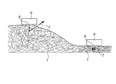
牧草水分測定装置20は、刈り取られた牧草1を取り込んで圧縮し、圧縮された状態で牧草1の水分量を測定する。牧草水分測定装置20は牧草地を走行する作業車に装着され、作業車の走行に伴って移動しながら、牧草1の水分量を測定する。牧草水分測定装置20は、分光分析器(品質測定器に相当)9と、送草管21と、掻き込み部(取草部に相当)22とを備える。
The grass moisture measuring device 20 takes in the cut grass 1 and compresses it, and measures the water content of the grass 1 in the compressed state. The grass moisture measuring device 20 is attached to a work vehicle traveling on the pasture, and measures the moisture content of the grass 1 while moving along with the traveling of the work vehicle. The grass moisture measuring device 20 includes a spectroscopic analyzer (corresponding to a quality measuring device) 9, a grass feeding pipe 21, and a scraping portion (corresponding to a weeding portion) 22.
送草管21は、2つの側壁21aと、底部21bと、天板部21cとを備える管状構造である。例えば、側壁21a、底部21b、天板部21cは、いずれも板状の部材である。2つの側壁21aは、それぞれ底部21bの両端部に立設されて、互いに向かい合って配置される。天板部21cは、送草管21の前側領域において、2つの側壁21aにまたがる態様で、底部21bと向い合うように設けられる。ここで、送草管21の前側端部は、牧草1が取り入れられる送草管21の入口に相当する。
The feeding pipe 21 has a tubular structure including two side walls 21a, a bottom portion 21b, and a top plate portion 21c. For example, the side wall 21a, the bottom portion 21b, and the top plate portion 21c are all plate-shaped members. The two side walls 21a are erected at both ends of the bottom 21b and are arranged to face each other. The top plate portion 21c is provided in the front region of the feeding pipe 21 so as to face the bottom portion 21b in a manner straddling the two side walls 21a. Here, the front end portion of the grass feeding pipe 21 corresponds to the entrance of the feeding pipe 21 into which the grass 1 is taken.
掻き込み部22は、送草管21の前側領域において、2つの側壁21aにまたがる態様で、2つの側壁21aにまたがる軸芯Pを中心に回転可能に軸支される。掻き込み部22は、シリンダ22aと羽根22bとを備える。シリンダ22aは、軸芯Pを中心に回転する円柱状の部材である。羽根22bはシリンダ22aから突出する態様で、シリンダ22aの表面に回転方向に並んで複数設けられる。羽根22bは、シリンダ22aの回転に伴って軸芯Pを中心に回転し、牧草1を掻き込んで送草管21の内部に牧草1を詰め込む。例えば、羽根22bは、シリンダ22aに4枚設けられる。また、それぞれの羽根22bは先端に複数の爪22cを有することが好ましい。爪22cが設けられることにより、羽根22bは効率的に牧草1を掻き込むことができる。また、それぞれの羽根22bは、先端領域が回転方向に曲げられても良い。これによっても、羽根22bは効率的に牧草1を掻き込むことができる。
The scraping portion 22 is rotatably supported around the shaft core P straddling the two side walls 21a in a mode straddling the two side walls 21a in the front region of the feeding pipe 21. The scraping portion 22 includes a cylinder 22a and a blade 22b. The cylinder 22a is a columnar member that rotates about the axis P. A plurality of blades 22b are provided on the surface of the cylinder 22a side by side in the rotational direction in a manner of projecting from the cylinder 22a. The blades 22b rotate around the shaft core P with the rotation of the cylinder 22a, scrape the grass 1 and pack the grass 1 inside the feeding pipe 21. For example, four blades 22b are provided on the cylinder 22a. Further, it is preferable that each blade 22b has a plurality of claws 22c at its tip. By providing the claws 22c, the blades 22b can efficiently scrape the grass 1. Further, the tip region of each blade 22b may be bent in the rotational direction. This also allows the blades 22b to efficiently scrape the grass 1.
掻き込み部22は、牧草1の少なくとも一部を掻き込んで送草管21の入り口から内部に牧草1を次々に詰め込む。そのため、送草管21内の牧草1は、圧縮されてその密度が高くなる。送草管21内を通過した牧草1は、送草管21の後端である排出口から排出される。排出された牧草1は、掻き込まれなかった牧草1と合流する。
The scraping section 22 scrapes at least a part of the grass 1 and packs the grass 1 into the inside one after another from the entrance of the feeding pipe 21. Therefore, the grass 1 in the feeding pipe 21 is compressed and its density becomes high. The grass 1 that has passed through the feeding pipe 21 is discharged from the discharge port at the rear end of the feeding pipe 21. The discharged grass 1 merges with the unscraped grass 1.
分光分析器9は、送草管21の上部領域に、2つの側壁21aにまたがる態様で設けられる。例えば、分光分析器9は、天板部21cより後方に天板部21cと接して設けられる。分光分析器9は、2つの側壁21aの間の送草管21の内側に測定ヘッド8が向かうように配置され、測定ヘッド8は送草管21の内部で圧縮された牧草1と向い合う。このような構成により、分光分析器9は、送草管21の内部で圧縮された牧草1の水分量を測定することができる。分光分析器9は、測定ヘッド8から近赤外線光等の光7(図4参照)を牧草1に照射し、牧草1を透過し、反射することを繰り返して戻った光7(図4参照)を測定ヘッド8で受光する。分光分析器9は、受光した光7(図4参照)を分光分析して、牧草1の水分量を測定する。
The spectroscopic analyzer 9 is provided in the upper region of the feeding tube 21 so as to straddle the two side walls 21a. For example, the spectroscopic analyzer 9 is provided in contact with the top plate portion 21c behind the top plate portion 21c. The spectroanalyzer 9 is arranged so that the measuring head 8 faces the inside of the feeding pipe 21 between the two side walls 21a, and the measuring head 8 faces the grass 1 compressed inside the feeding pipe 21. With such a configuration, the spectroscopic analyzer 9 can measure the water content of the grass 1 compressed inside the grass feeding tube 21. The spectroscopic analyzer 9 irradiates the grass 1 with light 7 (see FIG. 4) such as near-infrared light from the measurement head 8, transmits the light 7 through the grass 1, and repeatedly reflects the light 7 (see FIG. 4). Is received by the measuring head 8. The spectroscopic analyzer 9 spectroscopically analyzes the received light 7 (see FIG. 4) to measure the water content of the grass 1.
以上のような構成により、送草管21内で十分に圧縮された牧草1に対して、分光分析器9は光7(図4参照)を照射することができるため、後に図4を用いて詳述するように、照射した光7(図4参照)が牧草1で乱反射することが抑制される。その結果、分光分析器9は、牧草1を透過した光(図4参照)を適切に受光して牧草1の水分量を精度良く測定することができる。
With the above configuration, the spectroscopic analyzer 9 can irradiate the grass 1 sufficiently compressed in the grass feeding tube 21 with light 7 (see FIG. 4). Therefore, FIG. 4 will be used later. As will be described in detail, the diffused reflection of the irradiated light 7 (see FIG. 4) on the grass 1 is suppressed. As a result, the spectroscopic analyzer 9 can appropriately receive the light transmitted through the grass 1 (see FIG. 4) and measure the water content of the grass 1 with high accuracy.
また、送草管21は環状構造であるため、送草管21の内部の少なくとも分光分析器9の近傍は遮光され、送草管21の内部に詰め込まれた牧草1には外部からの光の入射が抑制される。このことからも、分光分析器9は、牧草1を透過した光(図4参照)のみを適切に受光して牧草1の水分量を精度良く測定することができる。
Further, since the grass feeding tube 21 has an annular structure, at least the vicinity of the spectroscopic analyzer 9 inside the feeding tube 21 is shielded from light, and the grass 1 packed inside the feeding tube 21 receives light from the outside. Incident is suppressed. From this as well, the spectroscopic analyzer 9 can appropriately receive only the light transmitted through the grass 1 (see FIG. 4) and measure the water content of the grass 1 with high accuracy.
また、残置された牧草1は、乾燥速度の差等により、牧草地の上層部と下層部とで水分量にムラが生じる場合がある。牧草水分測定装置20を用いると、牧草1は、掻き込み部22にて掻き込まれる際に攪拌、混合される。その結果、水分量にムラのある牧草1が混ざり合った状態で分光分析器9に対して供給され、分光分析器9は、牧草地に残置された牧草1の平均的な水分量を測定することできる。
In addition, the remaining grass 1 may have uneven water content between the upper and lower layers of the pasture due to differences in drying speed and the like. When the grass moisture measuring device 20 is used, the grass 1 is agitated and mixed when it is scraped by the scraping portion 22. As a result, the grass 1 having an uneven water content is supplied to the spectrophotometer 9 in a mixed state, and the spectrophotometer 9 measures the average water content of the grass 1 left in the pasture. Can be done.
〔作業車〕
本実施形態に係る作業車は、上述の牧草水分測定装置20が装着される。図2を参照しながら図3を用いて、本実施形態に係る作業車が牧草水分測定装置20を使用する態様例について説明する。以下の説明は、作業車としてトラクタTが用いられる場合を例とした説明である。 [Work vehicle]
The work vehicle according to the present embodiment is equipped with the above-mentioned grassmoisture measuring device 20. An example in which the work vehicle according to the present embodiment uses the grass moisture measuring device 20 will be described with reference to FIG. The following description is based on the case where the tractor T is used as the work vehicle.
本実施形態に係る作業車は、上述の牧草水分測定装置20が装着される。図2を参照しながら図3を用いて、本実施形態に係る作業車が牧草水分測定装置20を使用する態様例について説明する。以下の説明は、作業車としてトラクタTが用いられる場合を例とした説明である。 [Work vehicle]
The work vehicle according to the present embodiment is equipped with the above-mentioned grass
牧草水分測定装置20は、トラクタTの機体前端(例えば、機体フレームの前端)に支持部13が接続される態様で、トラクタTに装着される。
The grass moisture measuring device 20 is attached to the tractor T in such a manner that the support portion 13 is connected to the front end of the tractor T (for example, the front end of the frame).
牧草水分測定装置20は、トラクタTが前進する場合に使用されても、トラクタTが後進する場合に使用されても良いが、使用状態においてトラクタTの進行方向前方に送草管21の入口が向くように装着される。つまり、トラクタTの進行方向前方に対して掻き込み部22が分光分析器9よりも前になるように、牧草水分測定装置20は装着される。
The grass moisture measuring device 20 may be used when the tractor T moves forward or when the tractor T moves backward, but in the used state, the entrance of the grass feeding pipe 21 is forward in the traveling direction of the tractor T. It is installed so that it faces. That is, the grass moisture measuring device 20 is mounted so that the scraping portion 22 is in front of the spectroscopic analyzer 9 with respect to the front of the tractor T in the traveling direction.
ここで、牧草地で生育された牧草1は、刈り取られ、牧草地で必要に応じて天日干し(乾燥)される。また、牧草1を収集しやすくするために、牧草1は牧草地に適宜残置され、例えば、畝状に配置される場合もある。トラクタTは、このような牧草地の刈り取られた牧草1上を走行し、掻き込み部22はトラクタTの走行に伴って牧草1を掻き込み、送草管21内で牧草1が圧縮される。そして、分光分析器9は、圧縮された状態の牧草1の水分量を測定する。
Here, the pasture 1 grown in the pasture is cut and dried in the sun (dried) as needed in the pasture. Further, in order to facilitate the collection of the grass 1, the grass 1 is appropriately left in the pasture, and may be arranged in a ridge shape, for example. The tractor T runs on the cut grass 1 of such a pasture, the scraping portion 22 scrapes the grass 1 as the tractor T runs, and the grass 1 is compressed in the feeding pipe 21. .. Then, the spectroscopic analyzer 9 measures the water content of the grass 1 in the compressed state.
〔水分量の測定〕
次に、図4を用いて、水分量の測定時において照射される光7の進み方と測定精度について説明する。 [Measurement of water content]
Next, with reference to FIG. 4, the traveling method and the measurement accuracy of the light 7 irradiated at the time of measuring the water content will be described.
次に、図4を用いて、水分量の測定時において照射される光7の進み方と測定精度について説明する。 [Measurement of water content]
Next, with reference to FIG. 4, the traveling method and the measurement accuracy of the light 7 irradiated at the time of measuring the water content will be described.
上述のように、刈り取られた牧草1は、牧草地に適宜残置され、牧草1は刈り取られたままに放置されたり、後の作業を行いやすいように畝状等に集められたりする。いずれにせよ、牧草地の牧草1は、特段の圧縮が行われず、自然な状態で、互いに隙間をもって疎な状態で存在する。
As described above, the cut grass 1 is appropriately left in the pasture, and the grass 1 is left as it is cut or collected in a ridge shape so that later work can be easily performed. In any case, the pasture 1 in the pasture is not particularly compressed and exists in a natural state, in a sparse state with gaps from each other.
このように、疎な状態で存在する牧草1に対して、分光分析器9から光7を照射すると、牧草1間に空間があるため、牧草1で光7が反射する。このように、照射した光7が乱反射すると、光が無秩序に散乱し、光7は分光分析器9の測定ヘッド8に戻らない場合がある。この場合、牧草1の水分量の測定が行えないことになる。結果として、照射した光7に比べて、測定ヘッド8に戻る光7の割合が小さくなり、牧草1の水分量を正確に測定できなくなる。
In this way, when the light 7 is irradiated from the spectrophotometer 9 to the grass 1 existing in a sparse state, the light 7 is reflected by the grass 1 because there is a space between the grass 1. In this way, when the irradiated light 7 is diffusely reflected, the light is scattered in a disorderly manner, and the light 7 may not return to the measurement head 8 of the spectrophotometer 9. In this case, the water content of the grass 1 cannot be measured. As a result, the proportion of the light 7 returning to the measuring head 8 becomes smaller than that of the irradiated light 7, and the water content of the grass 1 cannot be accurately measured.
これに対して、密な状態で存在する牧草1に対して、分光分析器9から光7を照射すると、牧草1が密集しているため、ある牧草1を透過した光7は、すぐに次の牧草1に到達して乱反射することが少ない。そのため、いくつかの牧草1を透過した光は広がらず、測定ヘッド8に戻りやすくなる。その結果、十分な量の光7が牧草1を透過した後に測定ヘッド8に戻る可能性が高くなり、牧草1の水分量を精度良く測定することができるようになる。
On the other hand, when the light 7 is applied to the grass 1 existing in a dense state from the spectroscopic analyzer 9, the grass 1 is densely packed, so that the light 7 transmitted through the grass 1 is immediately next. It rarely reaches the grass 1 and reflects diffusely. Therefore, the light transmitted through some grasses 1 does not spread, and it becomes easy to return to the measurement head 8. As a result, there is a high possibility that a sufficient amount of light 7 will return to the measuring head 8 after passing through the grass 1, and the water content of the grass 1 can be measured accurately.
そして、牧草1の水分量を精度良く測定することができるため、次の作業を行うのに最適なタイミングを計って作業計画を立てたり、添加剤の添加等の適切な処置を行ったりすることができる。また、通信装置(図示せず)をさらに設け、牧草1を貯留して乾燥させるサイロ、あるいはサイロ等を管理するサーバ等に測定した水分量を送信することにより、貯留される牧草1の水分量に応じたサイロ等の管理を行うこともできる。以上のことにより、高品質な飼料を容易に作成することができる。さらに、牧草地を走査的に走行しながら水分量を測定することができるため、GPS等で牧草地における位置情報を取得できる場合には、位置情報と水分量とを関連付けて、牧草地における水分量の分布をマップとして生成することもできる。
Since the water content of the grass 1 can be measured accurately, it is necessary to make a work plan at the optimum timing for the next work and take appropriate measures such as adding additives. Can be done. In addition, a communication device (not shown) is further provided, and the measured water content is transmitted to a silo that stores and dries the grass 1 or a server that manages the silo, etc., so that the water content of the grass 1 is stored. It is also possible to manage silos and the like according to the above. From the above, high quality feed can be easily prepared. Furthermore, since the water content can be measured while scanning the pasture, if the position information in the pasture can be obtained by GPS or the like, the water content in the pasture is associated with the position information and the water content. The distribution of quantities can also be generated as a map.
図1,図2,図4に示すように、本実施形態に係る牧草水分測定装置20は、牧草1を送草管21に押し込んで圧縮することにより、密な状態の牧草1に対して分光分析器9が光7を照射することができる。そのため、牧草1の水分量を精度良く測定することができる。
As shown in FIGS. 1, 2, and 4, the grass moisture measuring device 20 according to the present embodiment disperses the grass 1 in a dense state by pushing the grass 1 into the feeding pipe 21 and compressing the grass 1. The analyzer 9 can irradiate the light 7. Therefore, the water content of the grass 1 can be measured accurately.
ここで、分光分析器9は、光7を用いて水分量を測定するため、分光分析器9が照射した光7以外の、外部から入力する光が測定ヘッド8に入力すると、水分量の正確な測定ができなくなる。
Here, since the spectroscopic analyzer 9 measures the water content using the light 7, when the light input from the outside other than the light 7 irradiated by the spectroscopic analyzer 9 is input to the measurement head 8, the water content is accurate. It becomes impossible to make a good measurement.
本実施形態に係る牧草水分測定装置20では、上述のように、分光分析器9は、送草管21の上部領域を覆う態様で設けられる。そのため、分光分析器9の測定ヘッド8は、分光分析器9で覆われた領域の牧草1に対して光7を照射することができ、分光分析器9を含む送草管21で光の侵入が遮断された領域の牧草1の水分量を測定することができる。その結果、測定ヘッド8に外部からの光が入射することが抑制され、牧草1の水分量をより精度良く測定することができる。
In the grass moisture measuring device 20 according to the present embodiment, as described above, the spectroscopic analyzer 9 is provided so as to cover the upper region of the grass feeding tube 21. Therefore, the measurement head 8 of the spectroscopic analyzer 9 can irradiate the grass 1 in the area covered by the spectroscopic analyzer 9 with light 7, and the light penetrates through the grass feeding tube 21 including the spectroscopic analyzer 9. The water content of the grass 1 in the area where the light is blocked can be measured. As a result, the light from the outside is suppressed from being incident on the measuring head 8, and the water content of the grass 1 can be measured more accurately.
〔実施形態1の別実施形態〕
(1)牧草水分測定装置20は、トラクタTの機体後端から後方に突出して配置されることが可能で、牧草水分測定装置20はトラクタTの前進走行に伴って牧草地上を牽引される態様で使用される。また、牧草水分測定装置20は、トラクタTの下側部分、例えば前後の車輪4の間に配置されることが可能で、牧草水分測定装置20はトラクタTの前進走行に伴って牧草地を移動する態様で使用される。 [Another Embodiment of Embodiment 1]
(1) The grassmoisture measuring device 20 can be arranged so as to project rearward from the rear end of the tractor T, and the grass moisture measuring device 20 is towed on the grass ground as the tractor T travels forward. Used in. Further, the grass moisture measuring device 20 can be arranged in the lower portion of the tractor T, for example, between the front and rear wheels 4, and the grass moisture measuring device 20 moves in the pasture as the tractor T travels forward. It is used in the mode of
(1)牧草水分測定装置20は、トラクタTの機体後端から後方に突出して配置されることが可能で、牧草水分測定装置20はトラクタTの前進走行に伴って牧草地上を牽引される態様で使用される。また、牧草水分測定装置20は、トラクタTの下側部分、例えば前後の車輪4の間に配置されることが可能で、牧草水分測定装置20はトラクタTの前進走行に伴って牧草地を移動する態様で使用される。 [Another Embodiment of Embodiment 1]
(1) The grass
(2)牧草水分測定装置20が装着された作業車は、トラクタTのみならず、様々な作業車や、様々な作業を行うインプルメントが装着されたトラクタTであっても良い。そして、これらの作業車に装着された牧草水分測定装置20は、牧草地に残置された牧草1を送草管21に取り込み、送草管21内で牧草1の水分量を測定する。
(2) The work vehicle equipped with the grass moisture measuring device 20 may be not only a tractor T but also various work vehicles and a tractor T equipped with an implant for performing various operations. Then, the grass moisture measuring device 20 mounted on these work vehicles takes in the grass 1 left in the pasture into the grass feeding pipe 21 and measures the water content of the grass 1 in the feeding pipe 21.
例えば、牧草水分測定装置20は、図5に示すように、前側領域に刈取部Mが装着されたトラクタTの、後側領域あるいは下側領域に設けられても良い。また、牧草水分測定装置20は、自走式の草刈り車両の前側領域、後側領域あるいは下側領域に設けられても良く、装着可能な任意の領域に設けられる。
For example, as shown in FIG. 5, the grass moisture measuring device 20 may be provided in the rear region or the lower region of the tractor T in which the cutting portion M is mounted in the front region. Further, the grass moisture measuring device 20 may be provided in a front region, a rear region or a lower region of a self-propelled mowing vehicle, and is provided in an arbitrary region where it can be mounted.
トラクタTに装着された刈取部Mや自走式の草刈り車両は、牧草地に植立された牧草2を刈り取る。牧草地の刈り取られた牧草1は、牧草水分測定装置20が通過することに伴って送草管21に取り込まれ、水分量が測定される。これにより、効率的に牧草1の水分量を精度良く測定することができる。
The mowing unit M attached to the tractor T and the self-propelled mowing vehicle mow the mowing 2 planted in the pasture. The cut grass 1 in the pasture is taken into the grass feeding pipe 21 as the grass moisture measuring device 20 passes through, and the moisture content is measured. As a result, the water content of the grass 1 can be efficiently measured with high accuracy.
(3)また、牧草水分測定装置20が装着され作業車は、牧草地の牧草1を収集しながら作業走行を行う作業車であっても良い。このような作業車は、収集した牧草1を搬送する搬送経路3を備える。牧草水分測定装置20は、搬送経路3をバイパスする態様で、搬送経路3に装着される。
(3) Further, the work vehicle equipped with the grass moisture measuring device 20 may be a work vehicle that performs work while collecting grass 1 in the pasture. Such a work vehicle includes a transport path 3 for transporting the collected grass 1. The grass moisture measuring device 20 is attached to the transport path 3 in a manner of bypassing the transport path 3.
例えば、図6に示すように、作業車はハーベスタHとすることができる。ハーベスタHは、牧草地の牧草1を収集し、ローダワゴンW等に排出する。ローダワゴンW等は、収集された牧草1をサイロ等に搬送する。ハーベスタHは、収集した牧草1を搬送経路3で搬送し、搬送経路3からローダワゴンW等に牧草1を排出する。牧草水分測定装置20は、牧草水分測定装置20の入口と排出口とが搬送経路3に接続する態様で、この搬送経路3に装着される。例えば、牧草水分測定装置20は、アタッチメント等を介して搬送経路3に装着されても良く、搬送経路3内を搬送される牧草1の少なくとも一部を掻き込み部22が送草管21内に導くことができれば良い。また、図8に示すように、牧草水分測定装置20は、送草管21の少なくとも一か所に曲がり部21dを備える構成でも良い。これにより、容易に牧草水分測定装置20が搬送経路3に装着されると共に、搬送経路3内の牧草1を掻き込みやすいように掻き込み部22を配置する態様で、牧草水分測定装置20が搬送経路3に装着されやすくなる。
For example, as shown in FIG. 6, the work vehicle can be a harvester H. Harvester H collects pasture 1 in the pasture and discharges it to the loader wagon W or the like. The loader wagon W or the like transports the collected grass 1 to a silo or the like. The harvester H transports the collected grass 1 through the transport path 3, and discharges the grass 1 from the transport path 3 to the loader wagon W or the like. The grass moisture measuring device 20 is attached to the transport path 3 in such a manner that the inlet and the discharge port of the grass moisture measuring device 20 are connected to the transport path 3. For example, the grass moisture measuring device 20 may be attached to the transport path 3 via an attachment or the like, and at least a part of the grass 1 transported in the transport path 3 is scraped into the grass feed pipe 21. I just need to be able to guide you. Further, as shown in FIG. 8, the grass moisture measuring device 20 may be configured to include a bent portion 21d at at least one place of the grass feeding pipe 21. As a result, the grass moisture measuring device 20 is easily attached to the transport path 3, and the grass moisture measuring device 20 transports the grass 1 in the transport path 3 in such a manner that the scraping portion 22 is arranged so as to easily scrape the grass 1. It becomes easy to be attached to the path 3.
また、図7に示すように、作業車は、作業装置としてロールベーラBaを牽引するトラクタTや、自走式のロールベーラBaとすることができる。ロールベーラBaは、牧草地の牧草1を収集し、牧草1をロールベールに成形する。ロールベーラBaは、収集した牧草1をロールベールの成形領域に搬送経路3を介して搬送する。牧草水分測定装置20は、牧草水分測定装置20の入口と排出口とが搬送経路3に接続する態様で、この搬送経路3に装着される。例えば、牧草水分測定装置20は、アタッチメント等を介して搬送経路3に装着されても良く、搬送経路3内を搬送される牧草1の少なくとも一部を掻き込み部22が送草管21内に導くことができれば良い。また、図8に示すように牧草水分測定装置20は、送草管21の少なくとも一か所に曲がり部21dを備える構成でも良い。これにより、容易に牧草水分測定装置20が搬送経路3に装着されると共に、搬送経路3内の牧草1を掻き込みやすいように掻き込み部22を配置する態様で、牧草水分測定装置20が搬送経路3に装着されやすくなる。なお、図6から図8で例示した牧草水分測定装置20は、搬送経路3に設けられるため、支持部13が設けられることを要しない。
Further, as shown in FIG. 7, the work vehicle can be a tractor T for pulling the roll baler Ba or a self-propelled roll baler Ba as a work device. Roll veiler Ba collects pasture 1 in the pasture and shapes the pasture 1 into roll veil. The roll bachelor Ba transports the collected grass 1 to the molding region of the roll bachelor via the transport path 3. The grass moisture measuring device 20 is attached to the transport path 3 in such a manner that the inlet and the discharge port of the grass moisture measuring device 20 are connected to the transport path 3. For example, the grass moisture measuring device 20 may be attached to the transport path 3 via an attachment or the like, and at least a part of the grass 1 transported in the transport path 3 is scraped into the grass feed pipe 21. I just need to be able to guide you. Further, as shown in FIG. 8, the grass moisture measuring device 20 may be configured to include a bent portion 21d at at least one place of the grass feeding pipe 21. As a result, the grass moisture measuring device 20 is easily attached to the transport path 3, and the grass moisture measuring device 20 transports the grass 1 in the transport path 3 in such a manner that the scraping portion 22 is arranged so as to easily scrape the grass 1. It becomes easy to be attached to the path 3. Since the grass moisture measuring device 20 illustrated in FIGS. 6 to 8 is provided in the transport path 3, it is not necessary to provide the support portion 13.
以上のように、ハーベスタHやロールベーラBaに牧草水分測定装置20が設けられることにより、牧草1をサイロ等に搬送する直前、または、ロールベーラBaでロールベールを作成する直前に、牧草1の水分量を測定することができる。そのため、測定された牧草1の水分量に応じて、サイロ等で添加する添加剤を適切に調整したり、ロールベールの作成過程で水分調整に必要な添加剤の添加を行ったり、ロールベールの作成自体を中止したりする等の適切な処理を行うことが可能となる。
As described above, by providing the grass moisture measuring device 20 on the harvester H or the roll baler Ba, the water content of the grass 1 is immediately before the grass 1 is transported to a silo or the like, or immediately before the roll veil is created by the roll baler Ba. Can be measured. Therefore, depending on the measured water content of the grass 1, the additives to be added with a silo or the like can be appropriately adjusted, or the additives necessary for water content adjustment can be added in the process of making the roll bale. It is possible to perform appropriate processing such as canceling the creation itself.
(4)送草管21の断面積は一様でも良いが、送草管21の全体あるいは、分光分析器9の手前の少なくとも一部で、前端(入口)から後端(排出口)に向かう程断面積が小さくなっても良い。この場合、底部21b、側壁21a、天板部21cの少なくとも一つが、送草管21の内側に傾いて構成されても良いが、送草管21の内面において傾斜面を備えても良い。また、送草管21は底部21b、側壁21a、天板部21cを備える構成に限らず、掻き込まれた牧草1が送られる管であれば良く、断面形状は任意である。
(4) The cross-sectional area of the feeding tube 21 may be uniform, but the entire feeding tube 21 or at least a part in front of the spectrophotometer 9 is directed from the front end (entrance) to the rear end (exhaust port). The cross-sectional area may be as small as possible. In this case, at least one of the bottom portion 21b, the side wall 21a, and the top plate portion 21c may be configured to be inclined inward of the feeding pipe 21, but an inclined surface may be provided on the inner surface of the feeding pipe 21. Further, the grass feeding pipe 21 is not limited to the configuration provided with the bottom portion 21b, the side wall 21a, and the top plate portion 21c, and may be a pipe to which the scraped grass 1 is fed, and the cross-sectional shape is arbitrary.
(5)分光分析器9は水分量の測定に限らず、光学的に測定可能な様々な品質(特性)を測定することもできる。また、光7は、近赤外線に限らず、マイクロ波等の他の電磁波であっても良い。また、水分等の品質の測定は分光分析に限らず、静電容量を用いた測定等、種々の測定器・測定方法を用いることができる。
(5) The spectroscopic analyzer 9 is not limited to measuring the amount of water, but can also measure various qualities (characteristics) that can be measured optically. Further, the light 7 is not limited to near infrared rays, and may be other electromagnetic waves such as microwaves. Further, the measurement of the quality of water and the like is not limited to spectroscopic analysis, and various measuring instruments and measuring methods such as measurement using capacitance can be used.
(6)分光分析器9は、2つの側壁21aにまたがって設けられても良いが、2つの側壁21aの間に、2つの側壁21aと間隔を隔てて支持されても良い。
(6) The spectroscopic analyzer 9 may be provided across the two side walls 21a, but may be supported between the two side walls 21a at a distance from the two side walls 21a.
(7)牧草水分測定装置20は、ばね等の弾性体(図示せず)を介して作業車に支持されても良い。具体的には、牧草水分測定装置20は、ばね等の弾性体(図示せず)を介して支持部13の一端に支持される。支持部13の他端は、作業車に支持される。このような構成により、作業車の走行に伴って牧草水分測定装置20が牧草1の上を通過する際に、牧草水分測定装置20が牧草1の圧力で上昇しようとしても、ばね等の弾性体(図示せず)の弾性力により牧草水分測定装置20が下方に押し下げられる。そのため、牧草水分測定装置20が牧草1のうねり等に追随し、より効率的に牧草1を掻き込むことができる。
(7) The grass moisture measuring device 20 may be supported by the work vehicle via an elastic body (not shown) such as a spring. Specifically, the grass moisture measuring device 20 is supported by one end of the support portion 13 via an elastic body (not shown) such as a spring. The other end of the support portion 13 is supported by the work vehicle. With such a configuration, when the grass moisture measuring device 20 passes over the grass 1 as the work vehicle travels, even if the grass moisture measuring device 20 tries to rise by the pressure of the grass 1, an elastic body such as a spring The grass moisture measuring device 20 is pushed downward by the elastic force (not shown). Therefore, the grass moisture measuring device 20 can follow the swell of the grass 1 and scrape the grass 1 more efficiently.
(8)天板部21cは、掻き込み部22上を覆う位置に及んで設けられても良いし、掻き込み部22が設けられる送草管21の入り口付近を覆わないように設けられても良い。掻き込み部22は送草管21の内側で軸支されても良いが、牧草1を送草管21内に送り込むことができれば、送草管21から離れた位置に設けられても良い。取草部である掻き込み部22は、羽根22bが回転することにより牧草1を送草管21に取込む構成でも良いが、牧草1を送草管21に取込むことができる構成であれば任意の構成とすることができ、例えば、掻き込み部22は、牧草1を吸引する吸引器であっても良い。
(8) The top plate portion 21c may be provided so as to cover the position above the scraping portion 22, or may be provided so as not to cover the vicinity of the entrance of the feeding pipe 21 in which the scraping portion 22 is provided. good. The scraping portion 22 may be pivotally supported inside the grass feeding pipe 21, but may be provided at a position away from the grass feeding pipe 21 as long as the grass 1 can be fed into the grass feeding pipe 21. The scraping portion 22, which is a weeding portion, may have a configuration in which the grass 1 is taken into the grass feeding pipe 21 by rotating the blades 22b, but is a configuration in which the grass 1 can be taken into the feeding pipe 21. It can have any configuration, for example, the scraping portion 22 may be a suction device that sucks the grass 1.
(9)羽根22bは、シリンダ22aの幅方向に1枚設けられても良いが、シリンダ22aの幅方向に複数の羽根22bが設けられる構成であっても良い。すなわち、シリンダ22aの周方向に並ぶ羽根22bの少なくとも一部は、シリンダ22aの幅方向にならぶ複数の羽根22bから構成されても良い。
(9) One blade 22b may be provided in the width direction of the cylinder 22a, but a plurality of blades 22b may be provided in the width direction of the cylinder 22a. That is, at least a part of the blades 22b arranged in the circumferential direction of the cylinder 22a may be composed of a plurality of blades 22b arranged in the width direction of the cylinder 22a.
(10)分光分析器9は、天板部21cより後方に天板部21cと接して設けられる場合に限らず、天板部21cと間隔を空けて設けられても良く、分光分析器9の端部が天板部21c上に載置されるように設けられても良い。
(10) The spectroscopic analyzer 9 is not limited to the case where it is provided in contact with the top plate portion 21c behind the top plate portion 21c, and may be provided at a distance from the top plate portion 21c. The end portion may be provided so as to be placed on the top plate portion 21c.
(11)掻き込み部22は、作業車の走行速度に比例して送草管21の内部に送り込む牧草1の量を調整することが可能な構成とすることができる。これにより、送草管21に適切な量の牧草1が適切な速度で送り込まれ、効率的に牧草1を圧縮することができる。例えば、掻き込み部22は、作業者の走行速度に応じてシリンダ22aの回転速度が変わる構成であっても良い。
(11) The scraping unit 22 can be configured so that the amount of grass 1 fed into the grass feeding pipe 21 can be adjusted in proportion to the traveling speed of the work vehicle. As a result, an appropriate amount of grass 1 is sent to the grass feeding pipe 21 at an appropriate speed, and the grass 1 can be efficiently compressed. For example, the scraping portion 22 may have a configuration in which the rotation speed of the cylinder 22a changes according to the traveling speed of the operator.
<実施形態2>
〔牧草水分測定装置〕
まず、図9,図10を用いて、本実施形態に係る作業車に装着される牧草水分測定装置(品質測定装置に相当)の構成例について説明する。 <Embodiment 2>
[Grass moisture measuring device]
First, a configuration example of a grass moisture measuring device (corresponding to a quality measuring device) mounted on a work vehicle according to the present embodiment will be described with reference to FIGS. 9 and 10.
〔牧草水分測定装置〕
まず、図9,図10を用いて、本実施形態に係る作業車に装着される牧草水分測定装置(品質測定装置に相当)の構成例について説明する。 <
[Grass moisture measuring device]
First, a configuration example of a grass moisture measuring device (corresponding to a quality measuring device) mounted on a work vehicle according to the present embodiment will be described with reference to FIGS. 9 and 10.
牧草水分測定装置10は、刈り取られた牧草1を圧縮し、圧縮された状態で牧草1の水分量を測定する。牧草水分測定装置10は牧草地を走行する作業車に装着され、作業車の走行に伴って移動しながら、牧草地の牧草1の水分量を測定する。牧草水分測定装置10は、分光分析器(品質測定器に相当)9と、圧草装置12と、平行リンク構造の支持部13とを備える。牧草水分測定装置10は、支持部13に支持されるフレーム11をさらに備える。
The grass moisture measuring device 10 compresses the cut grass 1 and measures the water content of the grass 1 in the compressed state. The grass moisture measuring device 10 is attached to a work vehicle traveling in the pasture, and measures the moisture content of the grass 1 in the pasture while moving along with the traveling of the work vehicle. The grass moisture measuring device 10 includes a spectroscopic analyzer (corresponding to a quality measuring device) 9, a compaction device 12, and a support portion 13 having a parallel link structure. The grass moisture measuring device 10 further includes a frame 11 supported by the support portion 13.
圧草装置12はフレーム11に支持されて、牧草地の牧草1を押さえつけて圧草する。圧草装置12は、集草部12aと圧草部12bとを備える。
The weeding device 12 is supported by the frame 11 and presses the grass 1 in the pasture to weed. The weeding device 12 includes a weeding portion 12a and a weeding portion 12b.
集草部12aは、板状部材であり、フレーム11から前方に突出するように、フレーム11に設けられる。ここで、前方とは、牧草水分測定装置10が装着された作業車が、牧草1の水分量を測定する作業走行中に走行する方向に相当する。集草部12aの底面は、前方に向かう程立ち上がる形状である。言い換えると、集草部12aの底面は、前方に向かう程、地面からの高さが高くなる。具体的には、集草部12aの底面は、前側領域が上方に突出する曲面と、基端側(後側)領域が下方に突出する曲面とが組み合わされた構成である。集草部12aは、このような構成により、作業車の走行に伴って、牧草1を集草部12aの下方領域に効率的に集め、フレーム11の下方領域に導くことができる。
The grass collecting portion 12a is a plate-shaped member, and is provided on the frame 11 so as to project forward from the frame 11. Here, the front corresponds to the direction in which the work vehicle equipped with the grass moisture measuring device 10 travels during the work traveling for measuring the moisture content of the grass 1. The bottom surface of the grass collecting portion 12a has a shape that rises toward the front. In other words, the bottom surface of the grass collecting portion 12a becomes higher from the ground toward the front. Specifically, the bottom surface of the grass collecting portion 12a has a configuration in which a curved surface in which the front side region protrudes upward and a curved surface in which the proximal end side (rear side) region protrudes downward are combined. With such a configuration, the grass collecting portion 12a can efficiently collect the grass 1 in the lower region of the grass collecting portion 12a and guide it to the lower region of the frame 11 as the work vehicle travels.
圧草部12bは、フレーム11の底部領域に設けられる。集草部12aで集められた牧草は、集草部12aの傾斜に沿って押し付けられていき、圧草部12bの下部領域で圧縮された状態が維持される。圧草部12bは、板状部材、あるいは少なくとも下面が平面の部材である。圧草部12bの底面に対して集草部12aは傾斜し、圧草部12bの底面と集草部12aとは連続的に形成され、例えば、圧草部12bと集草部12aとは一体形成される。
The pressure grass portion 12b is provided in the bottom region of the frame 11. The grass collected in the grass collecting section 12a is pressed along the inclination of the grass collecting section 12a, and the compressed state is maintained in the lower region of the grass collecting section 12b. The pressure grass portion 12b is a plate-shaped member or a member having at least a flat lower surface. The weeding portion 12a is inclined with respect to the bottom surface of the weeding portion 12b, and the bottom surface of the weeding portion 12b and the weeding portion 12a are continuously formed. For example, the weeding portion 12b and the weeding portion 12a are integrated. It is formed.
分光分析器9は、圧草部12bに設けられ、牧草1の水分量を測定する。分光分析器9は、測定ヘッド8から近赤外線光等の光7(図4参照)を牧草1に照射し、牧草1を透過し、反射することを繰り返して戻った光7(図4参照)を測定ヘッド8で受光する。分光分析器9は、受光した光7(図4参照)を分光分析して、牧草1の水分量を測定する。
The spectroscopic analyzer 9 is provided in the weeding section 12b and measures the water content of the grass 1. The spectroscopic analyzer 9 irradiates the grass 1 with light 7 (see FIG. 4) such as near-infrared light from the measurement head 8, transmits the light 7 through the grass 1, and repeatedly reflects the light 7 (see FIG. 4). Is received by the measuring head 8. The spectroscopic analyzer 9 spectroscopically analyzes the received light 7 (see FIG. 4) to measure the water content of the grass 1.
圧草部12bには開口部12cが設けられる。分光分析器9は、圧草部12bの開口部12cにはめ込まれる態様で、圧草部12bに支持される。
An opening 12c is provided in the weeding portion 12b. The spectrophotometer 9 is supported by the weeding portion 12b in a manner of being fitted into the opening 12c of the weeding portion 12b.
以上のような構成により、圧草装置12により十分に圧縮された牧草1に対して、分光分析器9は光7(図4参照)を照射することができるため、先に図4を用いて詳述されたように、照射した光7(図4参照)が牧草1で乱反射することが抑制される。その結果、分光分析器9は、牧草1を透過した光(図4参照)を適切に受光して牧草1の水分量を精度良く測定することができる。
With the above configuration, the spectroscopic analyzer 9 can irradiate the grass 1 sufficiently compressed by the weed control device 12 with light 7 (see FIG. 4), so that FIG. 4 is used first. As described in detail, the diffused reflection of the irradiated light 7 (see FIG. 4) on the grass 1 is suppressed. As a result, the spectroscopic analyzer 9 can appropriately receive the light transmitted through the grass 1 (see FIG. 4) and measure the water content of the grass 1 with high accuracy.
〔作業車〕
本実施形態に係る作業車は、上述の牧草水分測定装置10が装着される。図10を参照しながら図11を用いて、本実施形態に係る作業車が牧草水分測定装置10を使用する態様例について説明する。以下の説明は、作業車としてトラクタTが用いられる場合を例とした説明である。 [Work vehicle]
The work vehicle according to the present embodiment is equipped with the above-mentioned grassmoisture measuring device 10. An example in which the work vehicle according to the present embodiment uses the grass moisture measuring device 10 will be described with reference to FIG. The following description is based on the case where the tractor T is used as the work vehicle.
本実施形態に係る作業車は、上述の牧草水分測定装置10が装着される。図10を参照しながら図11を用いて、本実施形態に係る作業車が牧草水分測定装置10を使用する態様例について説明する。以下の説明は、作業車としてトラクタTが用いられる場合を例とした説明である。 [Work vehicle]
The work vehicle according to the present embodiment is equipped with the above-mentioned grass
牧草水分測定装置10は、トラクタTの機体前端(例えば、機体フレームの前端)に支持部13が接続される態様で、トラクタTに装着される。
The grass moisture measuring device 10 is attached to the tractor T in such a manner that the support portion 13 is connected to the front end of the tractor T (for example, the front end of the frame).
支持部13は平行リンク構造であるため、牧草水分測定装置10はトラクタTに対して上下揺動可能であり、トラクタTに対する上下揺動が許容される。
Since the support portion 13 has a parallel link structure, the grass moisture measuring device 10 can swing up and down with respect to the tractor T, and swings up and down with respect to the tractor T is allowed.
また、支持部13は平行リンク構造であるため、圧草部12bは地面に対して平行移動する。そのため、圧草部12bは、地面に対して常時平行な姿勢となる。その結果、圧草部12bは、牧草1をまんべんなく圧縮することができる。
Further, since the support portion 13 has a parallel link structure, the weeding portion 12b moves in parallel with the ground. Therefore, the weeding portion 12b is always in a posture parallel to the ground. As a result, the crushed grass portion 12b can evenly compress the grass 1.
牧草水分測定装置10は、トラクタTが前進する場合に使用しても、トラクタTが後進する場合に使用しても良いが、使用状態においてトラクタTの進行方向前方に、集草部12aが向くように装着される。つまり、トラクタTの進行方向前方に、圧草部12bより集草部12aが位置するように配置されるように、牧草水分測定装置10は装着される。
The grass moisture measuring device 10 may be used when the tractor T moves forward or when the tractor T moves backward, but the grass collecting portion 12a faces forward in the traveling direction of the tractor T in the used state. It is installed like this. That is, the grass moisture measuring device 10 is mounted so that the grass collecting portion 12a is located in front of the traveling direction of the tractor T with respect to the weeding portion 12b.
ここで、牧草地で生育された牧草1は、刈り取られ、牧草地で必要に応じて天日干し(乾燥)される。また、牧草1を収集しやすくするために、牧草1は牧草地に適宜残置され、例えば、畝状に配置される場合もある。トラクタTは、このような牧草地の刈り取られた牧草1上を走行し、トラクタTの走行に伴って、圧草装置12は牧草1を圧縮する。そして、分光分析器9は、圧縮された状態の牧草1の水分量を測定する。
Here, the pasture 1 grown in the pasture is cut and dried in the sun (dried) as needed in the pasture. Further, in order to facilitate the collection of the grass 1, the grass 1 is appropriately left in the pasture, and may be arranged in a ridge shape, for example. The tractor T runs on the cut grass 1 of such a pasture, and the crushing device 12 compresses the grass 1 as the tractor T runs. Then, the spectroscopic analyzer 9 measures the water content of the grass 1 in the compressed state.
図9,図10,図4に示すように、本実施形態に係る牧草水分測定装置10は、圧草装置12を備えることにより、牧草1を押し付けて圧縮することができ、密な状態の牧草1に対して分光分析器9が光7を照射することができる。そのため、牧草1の水分量を精度良く測定することができる。
As shown in FIGS. 9, 10, and 4, the grass moisture measuring device 10 according to the present embodiment is provided with the pressing device 12 so that the grass 1 can be pressed and compressed, and the grass in a dense state. The spectrophotometer 9 can irradiate 1 with light 7. Therefore, the water content of the grass 1 can be measured accurately.
ここで、分光分析器9は、光7を用いて水分量を測定するため、分光分析器9が照射した光7以外の、外部から入力する光が測定ヘッド8に入力すると、水分量の正確な測定が困難になる。
Here, since the spectroscopic analyzer 9 measures the water content using the light 7, when the light input from the outside other than the light 7 irradiated by the spectroscopic analyzer 9 is input to the measurement head 8, the water content is accurate. Measurement becomes difficult.
本実施形態に係る牧草水分測定装置10では、上述のように、分光分析器9は、圧草部12bに設けられた開口部12cに設置される。例えば、分光分析器9の底面が圧草部12bの底面と略面一となるように、分光分析器9は配置される。そのため、分光分析器9の測定ヘッド8は、圧草部12bおよび分光分析器9で押し付けられた状態の牧草1に対して光7を照射することができると共に、圧草部12bは分光分析器9より大きいために、分光分析器9および圧草部12bで光の侵入が遮断された領域の牧草1の水分量を測定することができる。その結果、測定ヘッド8に外部からの光が入射することが抑制され、牧草1の水分量をより精度良く測定することができる。
In the grass moisture measuring device 10 according to the present embodiment, as described above, the spectroscopic analyzer 9 is installed in the opening 12c provided in the grass section 12b. For example, the spectroscopic analyzer 9 is arranged so that the bottom surface of the spectroscopic analyzer 9 is substantially flush with the bottom surface of the weeding portion 12b. Therefore, the measurement head 8 of the spectroscopic analyzer 9 can irradiate the pasture portion 12b and the grass 1 pressed by the spectroscopic analyzer 9 with light 7, and the compacted grass portion 12b is the spectroscopic analyzer. Since it is larger than 9, the water content of the grass 1 in the region where the invasion of light is blocked can be measured by the spectrophotometer 9 and the compaction portion 12b. As a result, the light from the outside is suppressed from being incident on the measuring head 8, and the water content of the grass 1 can be measured more accurately.
〔実施形態2の別実施形態〕
(1)牧草水分測定装置10は、機体に上下揺動可能に支持される構成に限らず、機体に上下スライド可能に支持される構成であっても良い。 [Another Embodiment of Embodiment 2]
(1) The grassmoisture measuring device 10 is not limited to a configuration in which the grass moisture measuring device 10 is supported so as to be vertically swingable by the machine body, and may be a structure in which the grass moisture measuring device 10 is supported so as to be vertically slidable by the machine body.
(1)牧草水分測定装置10は、機体に上下揺動可能に支持される構成に限らず、機体に上下スライド可能に支持される構成であっても良い。 [Another Embodiment of Embodiment 2]
(1) The grass
(2)牧草水分測定装置10は、トラクタTの機体後端から後方に突出して配置されることが可能で、牧草水分測定装置10はトラクタTの前進走行に伴って牧草地上を牽引される態様で使用される。また、牧草水分測定装置10は、トラクタTの下側部分、例えば前後の車輪4の間に配置されることが可能で、牧草水分測定装置10はトラクタTの前進走行に伴って牧草地を移動する態様で使用される。
(2) The grass moisture measuring device 10 can be arranged so as to project rearward from the rear end of the tractor T, and the grass moisture measuring device 10 is towed on the grass ground as the tractor T travels forward. Used in. Further, the grass moisture measuring device 10 can be arranged in the lower portion of the tractor T, for example, between the front and rear wheels 4, and the grass moisture measuring device 10 moves in the pasture as the tractor T travels forward. It is used in the mode of
(3)トラクタT等の作業車は、牧草水分測定装置10のみを装着しても良いが、他のインプルメントと同時に牧草水分測定装置10を装着しても良い。例えば、図12に示すように、作業車が作業装置としてロールベーラBaを牽引するトラクタTの場合、牧草水分測定装置10は、ロールベーラBaに装着されても良いし、あるいは、図示しないが、自走可能なロールベーラBaに装着されても良い。この場合、牧草水分測定装置10は、ロールベーラBaの、牧草1を収集する領域よりも前方に配置される。
(3) A work vehicle such as a tractor T may be equipped with only the grass moisture measuring device 10, but may be equipped with the grass moisture measuring device 10 at the same time as other implants. For example, as shown in FIG. 12, in the case of a tractor T in which the work vehicle pulls the roll bachelor Ba as a work device, the grass moisture measuring device 10 may be attached to the roll bachelor Ba, or, although not shown, self-propelled. It may be attached to a possible roll bachelor Ba. In this case, the grass moisture measuring device 10 is arranged in front of the area of the roll bachelor Ba where the grass 1 is collected.
このようにロールベーラBaより前方の領域に牧草水分測定装置10が設けられることにより、ロールベーラBaでロールベールを作成する直前に牧草1の水分量を測定することができる。そのため、測定された牧草1の水分量に応じて、ロールベールの作成過程で水分調整に必要な添加剤の添加を行ったり、ロールベールの作成自体を中止したりする等の適切な処理を行うことが可能となる。
By providing the grass moisture measuring device 10 in the region in front of the roll baler Ba in this way, the water content of the grass 1 can be measured immediately before the roll baler is made with the roll baler Ba. Therefore, depending on the measured water content of the grass 1, appropriate treatments such as adding additives necessary for water adjustment in the process of making the roll bale or stopping the making of the roll bale itself are performed. It becomes possible.
同様に、牧草水分測定装置10は、トラクタTに牽引されたロールベーラBaや自走可能なロールベーラBaに限らず、トラクタTに牽引されたローダワゴンや自走可能ローダワゴン等の様々な構成の作業車に装着されても良い。これにより、様々な作業車の作業程で水分調整に必要な添加剤の添加を行ったり、作業自体を中止したりする等の適切な処理を行うことが可能となる。
Similarly, the grass moisture measuring device 10 is not limited to the roll baler Ba towed by the tractor T and the self-propelled roll baler Ba, but also works of various configurations such as a loader wagon towed by the tractor T and a self-propelled loader wagon. It may be mounted on a car. This makes it possible to perform appropriate treatments such as adding additives necessary for moisture adjustment and stopping the work itself in the work process of various work vehicles.
(4)また、牧草水分測定装置10が装着された作業車は、牧草地の刈り取られた牧草1の水分量を測定する場合に限らず、牧草1を刈り取ると共に牧草1の水分量を測定しても良い。例えば、図13に示すように、牧草水分測定装置10は、前側領域に刈取部Mが装着されたトラクタTの、後側領域あるいは下側領域に設けられても良い。また、牧草水分測定装置10は、自走式の草刈り車両の後側領域あるいは下側領域に設けられても良い。
(4) Further, the work vehicle equipped with the grass moisture measuring device 10 is not limited to measuring the water content of the cut grass 1 in the pasture, but also cuts the grass 1 and measures the water content of the grass 1. You may. For example, as shown in FIG. 13, the grass moisture measuring device 10 may be provided in the rear region or the lower region of the tractor T in which the cutting portion M is mounted in the front region. Further, the grass moisture measuring device 10 may be provided in the rear region or the lower region of the self-propelled mowing vehicle.
トラクタTに装着された刈取部Mや自走式の草刈り車両は、牧草地に植立された牧草2を刈り取る。牧草地の刈り取られた牧草1は、牧草水分測定装置10が通過することにより圧縮され、水分量が測定される。これにより、効率的に牧草1の水分量を精度良く測定することができる。
The mowing unit M attached to the tractor T and the self-propelled mowing vehicle mow the mowing 2 planted in the pasture. The cut grass 1 in the pasture is compressed by passing through the grass moisture measuring device 10, and the moisture content is measured. As a result, the water content of the grass 1 can be efficiently measured with high accuracy.
(5)圧草装置12は、走行に伴って牧草1を圧縮する構成に限らず、機械的に牧草1を押圧する構成としても良い。
(5) The weeding device 12 is not limited to the configuration of compressing the grass 1 as it travels, and may be configured to mechanically press the grass 1.
(6)圧草部12bは開口部12cを設けず、圧縮された状態の牧草1の水分量を測定できれば、牧草水分測定装置10は任意の位置に設けられても良い。例えば、牧草水分測定装置10は圧草部12bの下面に支持される構成とすることもできる。
(6) The grass moisture measuring device 10 may be provided at an arbitrary position as long as the compressed grass portion 12b is not provided with the opening 12c and the water content of the compressed grass 1 can be measured. For example, the grass moisture measuring device 10 may be configured to be supported on the lower surface of the crushed grass portion 12b.
(7)分光分析器9は水分量の測定に限らず、光学的に測定可能な様々な品質(特性)を測定することもできる。また、光7は、近赤外線に限らず、マイクロ波等の他の電磁波であっても良い。また、水分等の品質の測定は分光分析に限らず、静電容量を用いた測定等、種々の測定器・測定方法を用いることができる。
(7) The spectroscopic analyzer 9 is not limited to measuring the amount of water, but can also measure various qualities (characteristics) that can be measured optically. Further, the light 7 is not limited to near infrared rays, and may be other electromagnetic waves such as microwaves. Further, the measurement of the quality of water and the like is not limited to spectroscopic analysis, and various measuring instruments and measuring methods such as measurement using capacitance can be used.
(8)牧草水分測定装置10は、圧草装置12を下方に付勢するばね等の弾性体(図示せず)を備えても良い。ばね等の弾性体(図示せず)の弾性力により圧草部12bが下方に押し下げられて圧草部12bが牧草1をしっかりと押圧する。
(8) The grass moisture measuring device 10 may include an elastic body (not shown) such as a spring that urges the grass pressure device 12 downward. The pressure grass portion 12b is pushed downward by the elastic force of an elastic body (not shown) such as a spring, and the pressure grass portion 12b firmly presses the grass 1.
(9)集草部12aの底面は、2つの曲面が組み合わされる構成に限らず、下方に突出する1つの曲面のみを備えても良い。また、集草部12aの底面は曲面を備えなくても良い。さらに、集草部12aは、左右両端が徐々に立ち上がる形状でも良い。
(9) The bottom surface of the grass collecting portion 12a is not limited to a configuration in which two curved surfaces are combined, and may include only one curved surface protruding downward. Further, the bottom surface of the grass collecting portion 12a does not have to have a curved surface. Further, the grass collecting portion 12a may have a shape in which both the left and right ends gradually rise.
(10)分光分析器9は開口部12cにおいて、圧草部12b上に載置されても良い。この際、測定ヘッド8は開口部12cに配置され、測定ヘッド8の下方で圧縮された牧草1と近接するように、分光分析器9は支持される。
(10) The spectroscopic analyzer 9 may be placed on the weeding portion 12b at the opening 12c. At this time, the measurement head 8 is arranged in the opening 12c, and the spectrophotometer 9 is supported so as to be close to the grass 1 compressed below the measurement head 8.
本発明は、牧草に限らず様々な植物の品質を測定でき、様々な作業車に適用することができる。
The present invention can measure the quality of various plants, not limited to grass, and can be applied to various work vehicles.
1 牧草
3 搬送経路
9 分光分析器(品質測定器)
10 牧草水分測定装置(品質測定装置)
12 圧草装置
12c 開口部
13 支持部
15 弾性体
20 牧草水分測定装置(品質測定装置)
21 送草管
22 掻き込み部(取草部)
Ba ロールベーラ(作業車)
H ハーベスタ(作業車)
M 刈取部
T トラクタ(作業車) 1grass 3 transport path 9 spectroscopic analyzer (quality measuring instrument)
10 Grass moisture measuring device (quality measuring device)
12Weeding device 12c Opening 13 Support 15 Elastic body 20 Grass moisture measuring device (quality measuring device)
21Kusabe pipe 22 Scraping part (Kusabe part)
Ba roll baler (work vehicle)
H Harvester (work vehicle)
M Cutting section T tractor (work vehicle)
3 搬送経路
9 分光分析器(品質測定器)
10 牧草水分測定装置(品質測定装置)
12 圧草装置
12c 開口部
13 支持部
15 弾性体
20 牧草水分測定装置(品質測定装置)
21 送草管
22 掻き込み部(取草部)
Ba ロールベーラ(作業車)
H ハーベスタ(作業車)
M 刈取部
T トラクタ(作業車) 1
10 Grass moisture measuring device (quality measuring device)
12
21
Ba roll baler (work vehicle)
H Harvester (work vehicle)
M Cutting section T tractor (work vehicle)
Claims (11)
- 刈り取られた牧草が残置された牧草地で作業走行を行う作業車であって、
作業走行しながら前記牧草の品質を測定する品質測定装置を備え、
前記品質測定装置は、
筒状の送草管と、
牧草地に残置された前記牧草の少なくとも一部を前記送草管の一端から前記送草管の内部に送り込む取草部と、
前記送草管の内部で圧縮された前記牧草の品質を測定する品質測定器とを備える作業車。 It is a work vehicle that runs on the pasture where the cut grass is left.
Equipped with a quality measuring device that measures the quality of the grass while working
The quality measuring device is
With a tubular feeding tube,
A weeding section that feeds at least a part of the grass left in the pasture from one end of the feeding pipe into the inside of the feeding pipe.
A work vehicle equipped with a quality measuring instrument for measuring the quality of the grass compressed inside the feeding pipe. - 刈取部を有し、牧草地で刈取走行を行う作業車であって、
作業走行しながら牧草の品質を測定する品質測定装置を備え、
前記品質測定装置は、
筒状の送草管と、
前記刈取部によって刈り取られた前記牧草の少なくとも一部を前記送草管の一端から前記送草管の内部に送り込む取草部と、
前記送草管の内部で圧縮された前記牧草の品質を測定する品質測定器とを備える作業車。 It is a work vehicle that has a cutting section and runs cutting in the pasture.
Equipped with a quality measuring device that measures the quality of grass while working
The quality measuring device is
With a tubular feeding tube,
A weeding part that feeds at least a part of the grass cut by the cutting part from one end of the feeding pipe into the inside of the feeding pipe.
A work vehicle equipped with a quality measuring instrument for measuring the quality of the grass compressed inside the feeding pipe. - 前記送草管に送り込まれた前記牧草は前記送草管の他端から排出されて、前記送草管に送り込まれなかった他の前記牧草と合流される請求項1または2に記載の作業車。 The work vehicle according to claim 1 or 2, wherein the grass fed into the grass-feeding pipe is discharged from the other end of the grass-feeding pipe and merges with other grasses that have not been fed into the grass-feeding pipe. ..
- 前記作業車は前記牧草を集めて搬送する搬送経路を有し、
前記送草管の一端および他端が前記搬送経路に接続され、前記送草管は前記搬送経路をバイパスするように構成される請求項3に記載の作業車。 The work vehicle has a transport path for collecting and transporting the grass.
The work vehicle according to claim 3, wherein one end and the other end of the feeding pipe are connected to the carrying path, and the feeding pipe is configured to bypass the carrying path. - 前記取草部は、前記作業車の走行速度に比例して前記送草管の内部に送り込む前記牧草の量を調整する請求項1から4のいずれか一項に記載の作業車。 The work vehicle according to any one of claims 1 to 4, wherein the weeding section adjusts the amount of grass to be fed into the inside of the grass feeding pipe in proportion to the traveling speed of the work vehicle.
- 前記送草管の断面積は、前記送草管の一端から前記品質測定器が配置された領域までの区間の少なくとも一部で前記品質測定器に向かう程小さくなる請求項1から5のいずれか一項に記載の作業車。 Any of claims 1 to 5, wherein the cross-sectional area of the feeding pipe becomes smaller toward the quality measuring instrument in at least a part of a section from one end of the feeding pipe to the region where the quality measuring instrument is arranged. The work vehicle described in item 1.
- 牧草地で作業走行を行う作業車であって、
作業走行しながら牧草の品質を測定する品質測定装置を備え、
前記品質測定装置は、
前記牧草を押さえつける圧草装置と、
前記圧草装置によって押さえつけられた状態の前記牧草の品質を測定する品質測定器と、
前記作業車に対して上下移動可能に前記圧草装置を支持する支持部とを備える作業車。 It is a work vehicle that runs on the meadow.
Equipped with a quality measuring device that measures the quality of grass while working
The quality measuring device is
The weeding device that holds down the grass and
A quality measuring device for measuring the quality of the grass pressed by the weeding device, and
A work vehicle provided with a support portion that supports the weeding device so as to be vertically movable with respect to the work vehicle. - 前記圧草装置に設けられ、前記圧草装置を下方に押圧する弾性体を備える請求項7に記載の作業車。 The work vehicle according to claim 7, further comprising an elastic body provided on the weeding device and pressing the weeding device downward.
- 前記支持部は、機体に上下揺動可能に支持される請求項7または8に記載の作業車。 The work vehicle according to claim 7 or 8, wherein the support portion is supported by the machine body so as to be vertically swingable.
- 前記圧草装置は開口部を有し、
前記品質測定器は前記開口部に設けられる請求項7から9のいずれか一項に記載の作業車。 The weeding device has an opening
The work vehicle according to any one of claims 7 to 9, wherein the quality measuring instrument is provided in the opening. - 前記品質測定器は、
前記圧草装置に載置支持され、
前記開口部を通して品質を測定し、
前記圧草装置は、前記品質測定器より外周側にはみ出す請求項10に記載の作業車。
The quality measuring instrument is
It is placed and supported on the weeding device.
Quality is measured through the opening and
The work vehicle according to claim 10, wherein the pressure weed device protrudes from the quality measuring device to the outer peripheral side.
Priority Applications (2)
| Application Number | Priority Date | Filing Date | Title |
|---|---|---|---|
| EP20832439.2A EP3991544A4 (en) | 2019-06-26 | 2020-04-15 | Work vehicle |
| US17/606,865 US20220210970A1 (en) | 2019-06-26 | 2020-04-15 | Work Vehicle |
Applications Claiming Priority (4)
| Application Number | Priority Date | Filing Date | Title |
|---|---|---|---|
| JP2019-119005 | 2019-06-26 | ||
| JP2019119004A JP7118034B2 (en) | 2019-06-26 | 2019-06-26 | work vehicle |
| JP2019-119004 | 2019-06-26 | ||
| JP2019119005A JP7178968B2 (en) | 2019-06-26 | 2019-06-26 | work vehicle |
Publications (1)
| Publication Number | Publication Date |
|---|---|
| WO2020261719A1 true WO2020261719A1 (en) | 2020-12-30 |
Family
ID=74061129
Family Applications (1)
| Application Number | Title | Priority Date | Filing Date |
|---|---|---|---|
| PCT/JP2020/016493 WO2020261719A1 (en) | 2019-06-26 | 2020-04-15 | Work vehicle |
Country Status (3)
| Country | Link |
|---|---|
| US (1) | US20220210970A1 (en) |
| EP (1) | EP3991544A4 (en) |
| WO (1) | WO2020261719A1 (en) |
Families Citing this family (1)
| Publication number | Priority date | Publication date | Assignee | Title |
|---|---|---|---|---|
| DE102022112043A1 (en) * | 2022-05-13 | 2023-11-16 | Claas Selbstfahrende Erntemaschinen Gmbh | Harvester |
Citations (9)
| Publication number | Priority date | Publication date | Assignee | Title |
|---|---|---|---|---|
| US5758479A (en) * | 1995-05-26 | 1998-06-02 | David Staheli | Method and device for hay production |
| US6257072B1 (en) * | 1998-01-16 | 2001-07-10 | Claas Selbstfahrende Erntemaschinen Gmbh | Measuring device for mobile harvesting machines |
| US6421990B1 (en) * | 1999-05-19 | 2002-07-23 | Deere & Company | Measuring device for measuring components in and/or properties of crop material |
| US20050115309A1 (en) * | 2003-11-28 | 2005-06-02 | Lely Enterprises A.G. | Moisture measuring device and method |
| US20090286582A1 (en) * | 2008-05-15 | 2009-11-19 | Georg Kormann | Measuring arrangement for determining the constituents of a sample taken from a crop stream |
| WO2010003421A1 (en) * | 2008-07-08 | 2010-01-14 | Aarhus Universitet | Method for optimizing harvesting of crops |
| US20120192731A1 (en) * | 2010-04-29 | 2012-08-02 | Biziorek Stephane | Round Baler With Electrically Driven Roller |
| US20130042591A1 (en) * | 2011-08-16 | 2013-02-21 | Willi Behnke | Method and device for the state detection of a cutting device |
| JP2018185594A (en) | 2017-04-24 | 2018-11-22 | 株式会社クボタ | Pasture grass management system |
Family Cites Families (3)
| Publication number | Priority date | Publication date | Assignee | Title |
|---|---|---|---|---|
| DE10204941A1 (en) * | 2002-02-07 | 2003-08-21 | Deere & Co | Baling machine has a moisture sensor positioned on the side of the harvest material pressing chamber so that the sensor accurately measures moisture within the bale and not of surrounding air |
| DE10306725A1 (en) * | 2003-02-17 | 2004-09-16 | Claas Selbstfahrende Erntemaschinen Gmbh | Method and device for determining crop parameters |
| DE102006009575A1 (en) * | 2006-02-28 | 2007-09-06 | Claas Selbstfahrende Erntemaschinen Gmbh | Method and device for determining the compaction of crops |
-
2020
- 2020-04-15 US US17/606,865 patent/US20220210970A1/en active Pending
- 2020-04-15 WO PCT/JP2020/016493 patent/WO2020261719A1/en unknown
- 2020-04-15 EP EP20832439.2A patent/EP3991544A4/en active Pending
Patent Citations (9)
| Publication number | Priority date | Publication date | Assignee | Title |
|---|---|---|---|---|
| US5758479A (en) * | 1995-05-26 | 1998-06-02 | David Staheli | Method and device for hay production |
| US6257072B1 (en) * | 1998-01-16 | 2001-07-10 | Claas Selbstfahrende Erntemaschinen Gmbh | Measuring device for mobile harvesting machines |
| US6421990B1 (en) * | 1999-05-19 | 2002-07-23 | Deere & Company | Measuring device for measuring components in and/or properties of crop material |
| US20050115309A1 (en) * | 2003-11-28 | 2005-06-02 | Lely Enterprises A.G. | Moisture measuring device and method |
| US20090286582A1 (en) * | 2008-05-15 | 2009-11-19 | Georg Kormann | Measuring arrangement for determining the constituents of a sample taken from a crop stream |
| WO2010003421A1 (en) * | 2008-07-08 | 2010-01-14 | Aarhus Universitet | Method for optimizing harvesting of crops |
| US20120192731A1 (en) * | 2010-04-29 | 2012-08-02 | Biziorek Stephane | Round Baler With Electrically Driven Roller |
| US20130042591A1 (en) * | 2011-08-16 | 2013-02-21 | Willi Behnke | Method and device for the state detection of a cutting device |
| JP2018185594A (en) | 2017-04-24 | 2018-11-22 | 株式会社クボタ | Pasture grass management system |
Also Published As
| Publication number | Publication date |
|---|---|
| EP3991544A4 (en) | 2023-10-25 |
| EP3991544A1 (en) | 2022-05-04 |
| US20220210970A1 (en) | 2022-07-07 |
Similar Documents
| Publication | Publication Date | Title |
|---|---|---|
| US10694670B2 (en) | Method and arrangement for control of the speed of a baler | |
| EP3662741A1 (en) | Agricultural machine and method for operating an agricultural machine | |
| US10036663B2 (en) | Weighing round bales | |
| US9585310B2 (en) | Weighing round bales | |
| CA2388235C (en) | Yield monitor for forage crops | |
| RU2569566C2 (en) | Harvesting unit | |
| DE10236515C1 (en) | Crop characteristics measuring method for agricultural harvester compares spectral values provided by NIR or NIT sensor with reference values held in onboard computer | |
| WO2020261719A1 (en) | Work vehicle | |
| Shinners | Engineering principles of silage harvesting equipment | |
| EP1905292B1 (en) | Measuring device for measuring parameters | |
| EP3729949B1 (en) | Loading carriage with crop yield detection | |
| US7231814B2 (en) | Moisture measuring device and method | |
| US10058038B2 (en) | System and method for continuous bale forming | |
| EP1454519B1 (en) | Method and device for determination of crop parameters | |
| EP3020266A2 (en) | Loader wagon system and method for collecting halm material and measuring contents of the collected halm material | |
| US20230263131A1 (en) | System, method and apparatus for filling a feed mixer | |
| JP2021003054A (en) | Mobile vehicle | |
| US4263772A (en) | Pivotable forage harvester transfer chute | |
| JP7118034B2 (en) | work vehicle | |
| GB2606740A (en) | Residue monitoring | |
| Digman et al. | Technology background and best practices: Yield mapping in Hay and Forage | |
| Amiama et al. | Advances in Silage Harvest Operations | |
| DE102014010586B4 (en) | Agricultural harvester | |
| EP3756445A1 (en) | Arrangement and method for dosing of silage agent | |
| NL2016211B1 (en) | Agricultural vehicle with a loading chamber and storing method with a crop material property sensor. |
Legal Events
| Date | Code | Title | Description |
|---|---|---|---|
| 121 | Ep: the epo has been informed by wipo that ep was designated in this application |
Ref document number: 20832439 Country of ref document: EP Kind code of ref document: A1 |
|
| NENP | Non-entry into the national phase |
Ref country code: DE |
|
| ENP | Entry into the national phase |
Ref document number: 2020832439 Country of ref document: EP Effective date: 20220126 |