WO2020261612A1 - Organic matter treatment apparatus having steam generation function - Google Patents
Organic matter treatment apparatus having steam generation function Download PDFInfo
- Publication number
- WO2020261612A1 WO2020261612A1 PCT/JP2019/050432 JP2019050432W WO2020261612A1 WO 2020261612 A1 WO2020261612 A1 WO 2020261612A1 JP 2019050432 W JP2019050432 W JP 2019050432W WO 2020261612 A1 WO2020261612 A1 WO 2020261612A1
- Authority
- WO
- WIPO (PCT)
- Prior art keywords
- gas
- temperature
- processing
- furnace
- water
- Prior art date
Links
Images


Classifications
-
- B—PERFORMING OPERATIONS; TRANSPORTING
- B09—DISPOSAL OF SOLID WASTE; RECLAMATION OF CONTAMINATED SOIL
- B09B—DISPOSAL OF SOLID WASTE
- B09B3/00—Destroying solid waste or transforming solid waste into something useful or harmless
-
- F—MECHANICAL ENGINEERING; LIGHTING; HEATING; WEAPONS; BLASTING
- F23—COMBUSTION APPARATUS; COMBUSTION PROCESSES
- F23C—METHODS OR APPARATUS FOR COMBUSTION USING FLUID FUEL OR SOLID FUEL SUSPENDED IN A CARRIER GAS OR AIR
- F23C99/00—Subject-matter not provided for in other groups of this subclass
-
- F—MECHANICAL ENGINEERING; LIGHTING; HEATING; WEAPONS; BLASTING
- F23—COMBUSTION APPARATUS; COMBUSTION PROCESSES
- F23G—CREMATION FURNACES; CONSUMING WASTE PRODUCTS BY COMBUSTION
- F23G5/00—Incineration of waste; Incinerator constructions; Details, accessories or control therefor
- F23G5/02—Incineration of waste; Incinerator constructions; Details, accessories or control therefor with pretreatment
-
- F—MECHANICAL ENGINEERING; LIGHTING; HEATING; WEAPONS; BLASTING
- F23—COMBUSTION APPARATUS; COMBUSTION PROCESSES
- F23G—CREMATION FURNACES; CONSUMING WASTE PRODUCTS BY COMBUSTION
- F23G5/00—Incineration of waste; Incinerator constructions; Details, accessories or control therefor
- F23G5/08—Incineration of waste; Incinerator constructions; Details, accessories or control therefor having supplementary heating
- F23G5/14—Incineration of waste; Incinerator constructions; Details, accessories or control therefor having supplementary heating including secondary combustion
- F23G5/16—Incineration of waste; Incinerator constructions; Details, accessories or control therefor having supplementary heating including secondary combustion in a separate combustion chamber
-
- F—MECHANICAL ENGINEERING; LIGHTING; HEATING; WEAPONS; BLASTING
- F23—COMBUSTION APPARATUS; COMBUSTION PROCESSES
- F23G—CREMATION FURNACES; CONSUMING WASTE PRODUCTS BY COMBUSTION
- F23G5/00—Incineration of waste; Incinerator constructions; Details, accessories or control therefor
- F23G5/44—Details; Accessories
- F23G5/46—Recuperation of heat
-
- F—MECHANICAL ENGINEERING; LIGHTING; HEATING; WEAPONS; BLASTING
- F23—COMBUSTION APPARATUS; COMBUSTION PROCESSES
- F23G—CREMATION FURNACES; CONSUMING WASTE PRODUCTS BY COMBUSTION
- F23G5/00—Incineration of waste; Incinerator constructions; Details, accessories or control therefor
- F23G5/50—Control or safety arrangements
-
- F—MECHANICAL ENGINEERING; LIGHTING; HEATING; WEAPONS; BLASTING
- F23—COMBUSTION APPARATUS; COMBUSTION PROCESSES
- F23J—REMOVAL OR TREATMENT OF COMBUSTION PRODUCTS OR COMBUSTION RESIDUES; FLUES
- F23J15/00—Arrangements of devices for treating smoke or fumes
- F23J15/06—Arrangements of devices for treating smoke or fumes of coolers
-
- Y—GENERAL TAGGING OF NEW TECHNOLOGICAL DEVELOPMENTS; GENERAL TAGGING OF CROSS-SECTIONAL TECHNOLOGIES SPANNING OVER SEVERAL SECTIONS OF THE IPC; TECHNICAL SUBJECTS COVERED BY FORMER USPC CROSS-REFERENCE ART COLLECTIONS [XRACs] AND DIGESTS
- Y02—TECHNOLOGIES OR APPLICATIONS FOR MITIGATION OR ADAPTATION AGAINST CLIMATE CHANGE
- Y02E—REDUCTION OF GREENHOUSE GAS [GHG] EMISSIONS, RELATED TO ENERGY GENERATION, TRANSMISSION OR DISTRIBUTION
- Y02E20/00—Combustion technologies with mitigation potential
- Y02E20/30—Technologies for a more efficient combustion or heat usage
-
- Y—GENERAL TAGGING OF NEW TECHNOLOGICAL DEVELOPMENTS; GENERAL TAGGING OF CROSS-SECTIONAL TECHNOLOGIES SPANNING OVER SEVERAL SECTIONS OF THE IPC; TECHNICAL SUBJECTS COVERED BY FORMER USPC CROSS-REFERENCE ART COLLECTIONS [XRACs] AND DIGESTS
- Y02—TECHNOLOGIES OR APPLICATIONS FOR MITIGATION OR ADAPTATION AGAINST CLIMATE CHANGE
- Y02W—CLIMATE CHANGE MITIGATION TECHNOLOGIES RELATED TO WASTEWATER TREATMENT OR WASTE MANAGEMENT
- Y02W30/00—Technologies for solid waste management
- Y02W30/50—Reuse, recycling or recovery technologies
- Y02W30/82—Recycling of waste of electrical or electronic equipment [WEEE]
Definitions
- the present invention relates to an organic substance processing apparatus that thermally decomposes an organic substance such as a synthetic resin material so that it can be disposed of as ash and gas, and newly has an organic substance processing apparatus having a steam generating function.
- magnetized air By heating the organic matter put into the treatment tank that shuts off the outside air and supplying magnetized air (magnetized air) to the treatment tank in a suppressive manner, the organic matter is kept at a relatively low temperature without generating harmful substances such as dioxins.
- a processing technique for thermal decomposition is known. Since magnetized air activates oxygen by magnetic force to generate a large amount of negative ions, it has the property of causing a violent pyrolysis reaction with carbon molecules of organic matter. As a result, the organic matter is oxidatively decomposed into water, ash (inorganic matter, carbon, etc.) and gas (carbon dioxide, hydrocarbon, etc.).
- Patent Document 1 states that the magnetized air is supplied to the lower part of a processing tank in which the outside air is blocked and the charged organic substance is heated. A supply mechanism is attached, and when the temperature sensor detects that the inside of the processing tank has exceeded a certain temperature, the amount of magnetized air supplied by the magnetized air supply mechanism is adjusted for the magnetized air in the magnetized air supply mechanism. It is described that the electromagnetic valve is operated by the controller so as to reduce the supply amount.
- the temperature inside the treatment tank becomes an environment suitable for thermally decomposing organic matter
- the supply of magnetized air is automatically reduced by the cooperation of the solenoid valve, temperature sensor, and controller, and the organic matter burns at a high temperature. It can be prevented from becoming a state.
- the temperature inside the processing tank is not always uniform, and even if multiple temperature sensors are installed, it is difficult to accurately grasp the temperature inside the processing tank. There is a problem that the timing of operating the valve becomes inaccurate, and it is not possible to surely realize an environment suitable for thermally decomposing organic substances.
- the present inventor has invented the processing apparatus described in Patent Document 2 in advance, and has been able to reliably realize an environment suitable for thermally decomposing organic substances by supplying magnetized air.
- organic matter is effectively pyrolyzed by magnetized air, it does not become harmless to the organic matter generated by thermal decomposition, and gases such as hydrocarbons are released into the atmosphere without being treated.
- gases such as hydrocarbons are released into the atmosphere without being treated.
- the water vapor generated in the process of treatment is released as it is, there remains a problem that useful water vapor is not utilized.
- a heat exchanger C having a drum-shaped main body 141 is attached to the upper portion thereof, and the gas containing thermally decomposed hydrocarbons and the like is cooled in the main body 141. It becomes liquid, and when the liquid gradually accumulates on the bottom of the dome shape, the processing becomes troublesome.
- the present invention thermally decomposes an organic substance with magnetized air, detoxifies hydrocarbons and the like generated by the thermal decomposition, and makes it possible to release it into the atmosphere, and also utilizes steam generated in the process of treatment to make a steam boiler.
- the purpose is to supply steam to etc.
- the organic matter processing apparatus provided with the steam generation function of the present invention employs the means described in each claim of the claims. That is, the invention of claim 1 is a combustion processing mechanism B that heats the charged organic material and is connected to a processing tank A that suppressively supplies magnetized air for thermal decomposition and burns the gas generated by decomposition from the organic material.
- the combustion treatment mechanism B is a high-temperature treatment furnace that is heated by a burner. It has an X and a cooling treatment tank Y that stores water.
- the high temperature processing furnace X generates heat at a high temperature from the lower part to the intermediate part of the furnace, a gas receiving part that receives gas from the processing tank to the lower part of the furnace, a gas sending part that sends gas from the upper part of the furnace to the cooling treatment tank, and the middle part.
- a heating element in which a large number of ceramic heating elements that emit possible far infrared rays are mounted with a gap, a heating element that heats the heating element from the lower part of the furnace, and a high temperature of 800 ° C. or higher above the heating element. It includes a high temperature processing unit having a sustainable high temperature processing space and a high temperature holding unit that controls the temperature inside the furnace by a temperature sensor.
- the cooling treatment tank Y includes a cooling unit that cools the high-temperature gas of the high-temperature treatment furnace according to a temperature gradient through a bent communication cylinder having a plurality of fins arranged on the outer periphery extending toward a blower provided at the bottom.
- a water vapor generating part in which a storage space for storing water vapor is formed above the cooling part and a lead-out pipe for sending water vapor to the outside of the system is continuously provided in the storage space, and a high-pressure pump is arranged to form a tank under a constant pressure.
- the water supply unit that supplies water to the inside, the drainage unit that discharges water to the outside of the tank, and the water level sensors arranged at two or more positions above and below control the opening and closing of the water supply unit and the drainage unit to maintain the storage space. It is characterized by having a water level holding portion.
- the heating element is tubular, and a large number of heating elements are distributed vertically in the high temperature processing furnace, the lower stage is mounted vertically, and the upper stage is mounted horizontally. It is characterized by.
- a plurality of upright large-diameter cylindrical portions and small-diameter cylindrical portions are offset in the up-down direction and connected alternately up and down in the communication cylinder in the cooling treatment tank.
- the wall surface is curved so as to surround the communication port that is offset to connect the lower small diameter cylinder part, and gas can flow between both ends of the wall surface and the peripheral wall surface of the cylinder part. It is characterized in that a gas guide wall having a wide gap is erected near the center of the cylinder.
- the invention of claim 4 is characterized in that, in the above invention, the water level sensors of the water level holding portion are arranged at at least two or more positions above and below.
- an introduction pipe is vertically provided so as to face the bottom of the main body of the heat exchanger C, and an introduction path in which a trap pipe is arranged is provided at the end of the introduction pipe.
- a heating plate for vaporizing the dropped liquefied gas, an air supply port for sending the vaporized gas to a duct connected to the combustion processing mechanism B, and a vaporization chamber having an air supply pipe are formed, and the periphery of the vaporization chamber is formed.
- a heating space is formed by enclosing it with an intake for warm air on one side and an exhaust port on the other, and a connecting pipe for guiding warm air by connecting with the exhaust port of the cooling treatment tank Y is arranged on the intake side of the heating space. It is characterized in that the liquefied gas treatment mechanism D is attached.
- the present invention having the above configuration, magnetized air is supplied, organic substances are thermally decomposed in a suitable environment, and the ash formed on the bottom of the treatment tank is discharged as it is and disposed of, which is a heat exchanger from the treatment tank. It is sent into the high temperature processing furnace via.
- gas such as hydrocarbon is generated by thermal decomposition of organic matter, and the gas includes the subject of regulation such as hydrocarbon under the Air Pollution Control Act.
- the high-temperature processing furnace the continuous heat generation of a large number of heating elements that are heated by the heating unit and emit far infrared rays, and above the heating elements in the high-temperature environment on the surface of the heat-resistant material that has become hot due to heating.
- the temperature of the high temperature treatment space is stably maintained at a high temperature of 800 ° C. or higher.
- the dried hydrocarbons and the like supplied from the heat exchanger into the high-temperature processing furnace rise in the heating element group that radiates far infrared rays heated from the lower part of the high-temperature processing furnace by the heating unit.
- the temperature rises due to the heat generated by the heating element, and the hydrocarbons and the like reach the high temperature treatment space and are treated into harmless gas at a high temperature of 800 ° C. or higher.
- the hydrocarbons and the like are treated at high temperatures to become harmless substances of carbon dioxide and water (water vapor).
- the temperature inside the high-temperature processing furnace is heated by the burner to a high temperature state set while detecting the temperature inside the furnace with a temperature sensor, and is controlled by the high-temperature holding unit to a high temperature of 800 ° C. or higher.
- Hydrocarbons in the high-temperature processing space It is possible to maintain a higher temperature in the high temperature treatment space due to the heat generated by the combustion of the gas itself when it becomes a harmless gas. Then, while the high constant high temperature is maintained, the heating of the heating unit can be stopped, so that fuel can be saved.
- the high temperature gas is moved downward in the water of the tank through a cooling unit provided with a bent communication cylinder extending downward in the water, and in the middle of the cooling treatment tank, the high temperature gas is transferred to the water.
- a cooling unit provided with a bent communication cylinder extending downward in the water
- the high temperature gas is transferred to the water.
- a storage space capable of storing a certain volume of steam is formed above the cooling tanks connected to the high-temperature processing furnace. Then, in the process in which the high-temperature gas sent from the high-temperature processing furnace from 800 ° C. to 1200 ° C. passes through the communication cylinder, the heat exchanged there produces steam, which rises as bubbles, and the above It is stored in the storage space. At this time, since a plurality of fins are arranged in the communication cylinder, heat exchange is efficiently performed between the water in the cooling tank and the hot air passing through the communication cylinder through the fins, and a large amount of water vapor is generated.
- the water level sensor provided in the water level holding unit catches the water level and keeps the water level within a certain range, the water vapor storage space can hold a certain volume and surely stores a certain amount of water vapor. Can be done. Furthermore, since a high-pressure pump is installed in the water supply section, even if the pressure in the storage space rises, water can be forcibly supplied based on the command of the sensor, ensuring the volume of the storage space. Can be maintained at. As a result, it becomes possible to send high-temperature steam from the steam generator of this device to the outside of the system via a lead-out pipe, and supply steam to, for example, a steam turbine of a power generation device, a hospital, a heating device of a building, or the like. be able to.
- the large number of heating elements are distributed to the upper and lower stages in the high temperature processing furnace, and the lower stage is mounted vertically and the upper stage is mounted horizontally, so that the lower heating element group is a heating unit.
- the whole is directly heated by hot air from the bottom to the top to generate heat, and the heating element group in the upper stage receives heat from the heating element in the lower stage heated by the heating unit and generates heat to a temperature of 800 ° C. or higher.
- the high temperature treatment space above it can be stably maintained at a high temperature of 800 ° C. or higher. Then, it becomes possible to surely change hydrocarbons and the like into harmless gas in the stable high temperature.
- the invention of claim 3 is provided in a large-diameter cylindrical portion when a communication cylinder arranged in the cooling treatment tank meanders in water from side to side and moves high-temperature gas from the top to the bottom of the water tank.
- the gas guide wall guides the gas in the cylinder so as to pass through the gap with the peripheral wall surface, so that the high temperature gas is positively brought close to the water having a low temperature, so that the heat exchange efficiency can be improved. As a result, it becomes possible to efficiently cool the high-temperature gas.
- the water level sensors of the water level holding unit by arranging the water level sensors of the water level holding unit at at least two or more positions above and below, the upper and lower water levels are captured and the water level is kept within the range. It can be maintained at the volume specified by the lower limit.
- the liquefied gas treatment mechanism D by adding the liquefied gas treatment mechanism D, it is possible to treat the liquefied gas generated in the process of operating the organic matter processing apparatus of the present invention such as a heat exchanger, and at that time, the liquefied gas is treated. It is rational to use the mechanism that utilizes the cooperation between the layer A, the high-temperature processing furnace X, and the cooling treatment tank Y, and to utilize the warm air containing residual heat of about 140 to 160 ° C. via the cooling treatment tank Y as the heat source. It becomes a thing.
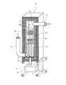
- FIG. 1 is a longitudinal side view of the organic matter processing apparatus provided with the steam generation function of the present invention.
- FIG. 2 is a vertical perspective view of the high temperature processing furnace.
- FIG. 3 is a perspective view of the communication cylinder.
- FIG. 4 is a vertical sectional side view of the treatment tank.
- FIG. 5 is a vertical sectional side view of the liquefied gas treatment mechanism.
- FIG. 6 is a perspective view of the liquefied gas treatment mechanism.
- the organic matter processing apparatus of the present invention As shown in FIG. 1, the organic matter is thermally decomposed in the processing tank A which heats the charged organic matter and suppressively supplies magnetized air for thermal decomposition.
- a combustion processing mechanism B for combusting the generated gas G is provided.
- a heat exchanger C for separating and removing the water contained in the gas G generated from the organic substance is provided between the treatment tank A and the combustion treatment mechanism B.
- a high-temperature processing furnace X that detoxifies the gas G such as hydrocarbons generated in the processing tank A at a high temperature and a gas G that has become high temperature in the high-temperature processing furnace X are cooled and discharged. It has a cooling treatment tank Y.
- the heat exchanger C is attached to the processing tank A, and the high temperature processing furnace X and the cooling processing tank Y are provided in the vicinity of the outside of the processing tank A.
- a liquefied gas treatment mechanism D can be attached between the heat exchanger C and the combustion treatment mechanism B.
- the treatment tank A is provided with a charging port 111 for charging the organic substance P in the upper part of the cylindrical tank, and an ash produced by thermally decomposing the organic substance P in the lower side surface.
- a discharge port 112 is provided for discharging the water.
- a magnetized air supply mechanism 105 for supplying the magnetized air M to the inside of the processing tank A from under the organic substance charged with the magnet 152 that magnetizes the air to make the magnetized air M is provided.
- an electromagnetic valve 106 for adjusting the amount of magnetized air M supplied from the magnetized air supply mechanism 105 to the inside of the processing tank A, and temperature sensors 171 and 172 for detecting the temperature inside the processing tank A are connected.
- a controller 108 for linking and controlling the solenoid valve 106 and the temperature sensors 171 and 172 is provided.
- the magnetized air M supplied from the magnetized air supply mechanism 105 is directed from the nozzle 151 toward the axial center of the processing tank A.
- a heat exchanger C having a drum-shaped main body portion 141 is attached to the upper portion of the processing tank A.
- the internal space of the main body 141 is connected to the space above the processing tank A.
- the gas G at 300 ° C. to 500 ° C. generated by the thermal decomposition of the organic substance P and rising inside the processing tank A enters the heat exchanger C, is cooled inside the gas G, and contains water and hydrocarbons contained in the gas G. Etc. are liquefied. A part of the gas dried by the heat exchanger C moves to the combustion processing mechanism B and flows in the processing tank A.
- the internal space of the main body 141 is connected to the next combustion processing mechanism B via a duct 11, but for safety, the movement of gas stops on the side surface of the duct due to a power failure or the like, and the gas is abnormal.
- An air-silider type shutter 134 that automatically opens when a high pressure is applied can be provided.
- the organic substance P thermally decomposed by the treatment tank A having the above-described configuration is supplied with water, ash (inorganic substances, carbon, etc.) and gas G (carbon dioxide) under the supply of magnetized air M from the nozzle 151 of the magnetized air supply mechanism 105. It is separated into carbon, hydrocarbons, etc.), and this gas G is sent to the combustion processing mechanism B via the heat exchanger C.
- a liquefied gas processing mechanism D can be added between the heat exchanger C and the combustion processing mechanism B described later. That is, a heat exchanger C having a drum-shaped main body 141 is attached to the upper part of the processing tank A, and a liquefied gas treatment mechanism shown below is attached to the lower part of the heat exchanger C main body 141. D can be attached.
- the liquefied gas refers to a gas body generated in the process of the apparatus of the present invention that has been cooled and liquefied for some reason, and is an object that is difficult to process as it is. As shown in FIGS. 5 and 6, the liquefied gas treatment mechanism D first forms a main body introduction path 143 in the lower part of the main body 141.
- the introduction pipe faces the main body 141.
- 143a is arranged, and a trap pipe 143b for storing the liquefied gas L in which hydrocarbons and the like are liquefied is connected to the arrangement thereof, and the tip portion thereof faces the vaporization chamber 145.
- the vaporization chamber 145 heats the liquefied gas L to vaporize it.
- a heating pan 145a is arranged at a position directly below the tip of the trap tube 143b, and the circumference of the vaporization chamber 145 including the heating pan 145a is arranged. Surrounded by a heating space 146.
- the heating dish 145a is responsible for vaporizing the liquefied gas L, and it is desirable that the heating dish 145a is made of ceramic for the purpose of avoiding rust from a liquid containing water.
- a connecting path 147 connected to the discharge port 25 is arranged on one side thereof. That is, the cooling treatment tank Y is provided with a cooling unit 7, and a blower 10 for forcibly moving the gas is connected to the gas delivery unit 24 of the cooling unit 7, and a combustion process is performed after that.
- a discharge port 25 for discharging the gas G detoxified by the mechanism B into the atmosphere is arranged at the end of the cooling treatment tank Y, but in the liquefied gas treatment mechanism D, this discharge port is provided.
- a connecting pipe 147a is added to the tip of the 25, and this is connected to the intake port 146a of the heating space 145.
- a blower 10 succeeding to the cooling treatment tank Y is arranged, and an exhaust pipe 147b that finally discharges the exhaust gas to the outside of the system is arranged at the tip of the blower 10.
- a duct introduction path 144 for treating the liquefied gas L generated in the duct 11 is provided at the lower end of the duct 11. It can be attached. That is, a duct 11 for moving the gas G is provided between the heat exchanger C at the upper part of the processing tank A and the high temperature processing furnace X, but the gas G cools in the process of the route and the liquefied gas L
- a duct introduction pipe 144a is connected to a part of the lower end portion which is a bent portion of the duct 11, and the tip thereof faces the inside of the vaporization chamber 145, and the end thereof is the trap.
- the tube 143b it can be arranged so as to be located directly above the heating dish 145a.
- the introduced liquefied gas L is treated in the same manner as the main body introduction path 143.
- the combustion treatment mechanism B connected to the heat exchanger C detoxifies and odorless gas G containing hydrocarbons and the like produced by thermal decomposition of the organic substance P in the treatment tank A at a high temperature. It is provided with a high-temperature processing furnace X for converting the heat, and a cooling treatment tank Y for cooling the gas G having a high temperature in the high-temperature processing furnace X with water W.
- the high temperature processing furnace X is installed in the vicinity of the processing tank A
- the cooling treatment tank Y is installed in the vicinity of the high temperature processing furnace X.
- a duct 11 for moving the gas G is provided between the heat exchanger C at the upper part of the processing tank A and the high temperature processing furnace X by connecting to the lower part of the high temperature processing furnace X.
- a duct 12 for moving the gas G is provided between the cooling treatment tank Y and the upper part of the high temperature treatment furnace X and the upper part of the cooling treatment tank Y.
- the high temperature processing furnace X is formed in a size having a volume capable of accommodating a heat generating portion 4 having a large number of exothermic materials 41 inside, and as shown in FIG. 2, the circumference of the furnace is 1300 ° C. or higher.
- the inside of the furnace is enclosed in a sealed state by using the heat-resistant material 31 that can withstand the high temperature of the above.
- FIG. 2 shows an embodiment in which three layers of heat-resistant material 31 formed in a thick plate shape are laminated and bonded to improve the heat-resistant performance in response to a high temperature of 1300 ° C. or higher.
- the heat generating part 4 forms a gap through which gas can pass through the ceramic heating element 41 having a heat storage property and having a far infrared radiation function.
- the structure is such that many are installed.
- the heating element 41 is made of a ceramic material that emits far infrared rays, has excellent heat storage properties, stores the heat when heated to a high temperature, and uses a material that generates heat by itself.
- a ceramic having silicon carbide as a main component and containing aluminum oxide, silicon dioxide and the like is formed in a tube and sintered.
- the heating element 41 shows a form in which a tubular heating element 41 is used in FIG. 2, but in addition to this, a heating element in which ceramic is formed in a rod shape, a plate shape, a block shape, or the like can also be used.
- the tubular heating element 41 is distributed in the high-temperature processing furnace X and fixed to the furnace wall of the heat-resistant material 31.
- the tubular heating element 41 is mounted vertically in the lower stage region by inserting it into the bottom wall with a gap between them.
- a gap is provided between them and the wall is inserted horizontally into the side wall
- a gap is provided between the two and the side wall is inserted horizontally.
- a mode in which the heating element group in the lower region and the heating element group in the middle region are distributed with a space between them is shown. Since the optimum size, number, mounting interval, arrangement, etc. of the heating element 41 are determined by the processing capacity and size of the furnace, the distribution of each stage is not limited to the above mode.
- the upper part of the heating element 41 provided in the upper region of the furnace is hollow to provide a high temperature treatment space 30.
- a high temperature processing unit 3 is provided.
- a gas receiving port 21 for supplying the gas G moved from the heat exchanger C into the furnace through the duct 11 is provided in the lower part of the high temperature treatment furnace X. As shown in FIG. 2, the gas receiving port 21 may be opened at the lower part of the side surface, or may be opened at the bottom surface (not shown).
- a heating unit 4 is provided in the lower part outside the high temperature treatment furnace X.
- the heating unit 4 has a burner 51 into which the nozzle 52 is inserted from the lower part to the upper part in the tank, and the burner 51 heats the heating element 41 group in the lower stage region, and the fuel is gas or oil. Can be used.
- the nozzle 52 of the burner 51 is provided on the bottom surface so that the gas G enters from below the heating element 41 group in the lower stage region, or the heating element 41 group in the lower stage region is not shown. It can also be provided at the bottom of the side so that gas can enter from the side of the.
- the high temperature treatment furnace X is provided with a high temperature holding portion 6 for controlling the temperature of the high temperature processing empty portion 3 and holding the temperature at a high temperature.
- a temperature sensor 61 is provided in the furnace toward the high temperature treatment space 30 in order to maintain the temperature of the high temperature treatment space 30 at a high temperature of, for example, at least 800 ° C.
- the temperature controller 60 connected to the temperature sensor 61 stops the operation of the burner 51.
- the temperature controller 60 operates the burner 51 to raise the temperature. That is, the burner 51 is not always operated, but is operated when the temperature is low at the start of operation or when the temperature inside the furnace temporarily drops below 800 ° C. to raise the temperature to 800 ° C. or higher. It is for raising.
- the gas G itself burns to generate thermal energy. Therefore, once the normal operating state is entered, the heat generated by the heat energy stored in the heating element 41 and the gas are generated in the high temperature processing space 30 at the high temperature of the surrounding heat resistant material 31 which is heated to a high temperature.
- a high temperature state of 800 ° C. to 1300 ° C. is maintained due to the addition of heat generated by combining G with oxygen. Therefore, the operation of the burner 51 can be temporarily stopped while the temperature is maintained at a high temperature of 800 ° C. or higher. Therefore, fuel can be saved.
- the high-temperature gas has a property of rising, and when the gas G entering from the gas receiving port 21 of the high-temperature processing furnace X rises between the heating elements 41 and passes through the gaps of the heating elements 41, the heating element 41 The temperature rises while increasing according to the temperature gradient, and reaches the high temperature processing space 30 to reach 800 ° C. to 1300 ° C.
- the organic matter P is thermally decomposed by the magnetized air M in the processing tank A, and the gas G generated is dried in the heat exchanger C at a temperature of about 200 ° C. and treated at a high temperature.
- the gas G rises in the furnace while raising the temperature through the heating elements 41 that are heated and is in a heating state, and becomes a high-temperature treatment space 30 having a high temperature of 800 ° C. or higher. To reach.
- the gas G reacts with oxygen in a high temperature environment of 800 ° C.
- the gas G containing water vapor and carbon dioxide generated by detoxifying the gas G generated by the thermal decomposition of the organic matter in the high temperature treatment furnace X moves to the upper part of the next cooling treatment tank Y via the duct 12. Let me.
- the cooling treatment tank Y As shown in FIG. 1, in the cooling treatment tank Y, the outer periphery of the tank filled with water W and sealed all around is covered with a heat insulating material 79 such as glass wool, and gas is contained in a communication cylinder 71 meandering in water. Is provided from the top to the bottom to cool the gas by heat exchange between the gas and water.
- the cooling unit 7 connects the upper end and the lower end of the communication cylinder 71 between the gas receiving unit 23 provided at the upper part of the tank and the gas delivery unit 24 provided at the bottom of the tank so as to communicate with the high temperature treatment furnace X. To do.
- a plurality of fins 78 for promoting more efficient heat exchange are arranged on the outer circumference of the communication cylinder 71 along the orbit around the communication cylinder 71.
- a blower 10 for forcibly moving the gas in the communication cylinder 71 from the upper part to the lower part of the tank is connected to the gas delivery unit 24.
- the blower 10 is attached to the tip of the duct 13, and the gas G discharged from the communication cylinder 71 is discharged into the atmosphere from the discharge port 25 at the end of the duct 13.
- the gas receiving unit 23 is communicably connected to the high temperature processing empty portion 3 of the high temperature processing furnace X via a duct 12.
- the gas delivery unit 24 is connected to the blower 10 for forcibly moving the gas in the communication cylinder 71 from the upper part to the lower part via the duct 13. Then, the gas G sucked from the communication cylinder 71 by the operation of the blower 10 is released into the atmosphere from the discharge port 25.
- the high temperature treatment furnace X raises the gas G into the furnace, whereas the high temperature gas G in the communication cylinder 71 resists the natural rising force. It is forcibly pulled down with a blower.
- a storage space 81 having a constant volume for storing water vapor is formed above the cooling unit 71 above the communication cylinder 71 of the cooling unit 7 of the cooling treatment tank Y, and water vapor is discharged from the storage space 81 to the outside of the system.
- a steam generating section 8 is provided in which a lead-out pipe 83 is provided with a discharge valve 82 for sending out the steam.
- the steam generating unit 8 is intended to utilize the steam generated in the communication cylinder 71, secures a space having a constant volume according to the purpose, and tries to temporarily store the steam in the space.
- the lead-out pipe 83 guides it to a device outside the system, for example, a boiler for power generation, a heating device for a hospital, a building, or the like, and effectively utilizes the steam generated in the organic matter processing device. ..
- a water level holding portion 9 for holding the storage space 81 is provided, and in conjunction with this, a water supply portion 92 for supplying water into the tank and a drainage portion 93 for discharging excess water to the outside of the tank are provided at the bottom of the tank.
- a water supply portion 92 for supplying water into the tank and a drainage portion 93 for discharging excess water to the outside of the tank are provided at the bottom of the tank.
- an upper limit sensor 91a and a lower limit sensor 91b arranged at least in the vertical position are arranged in the upper part of the tank, and a standard sensor 91c is arranged in the middle as necessary.
- the upper limit sensor 91a and the lower limit sensor 91b set the upper limit and the lower limit of the water level in the tank, the upper limit sensor 91a secures the minimum volume of the storage space 81, and the lower limit sensor 91b secures the maximum volume of the storage space 81.
- the standard sensor 91b is set to an average volume.
- the water supply unit 92 is provided with solenoid valves 92b and 93b of the water supply pipe 92a of the water supply unit 92 and the drainage pipe 93a of the drainage unit 93, and a water level controller that controls opening and closing based on the water level detected by the water level sensor 91. 90 is arranged. Then, a high-pressure pump 92c for forcibly supplying water is added to the water supply pipe 92a so as to surely maintain the volume of the storage space 81 even when the pressure in the storage space 81 increases.
- the direction of arrangement of the communication cylinder 71 is not an upward direction but a downward direction, and a cooling means is taken according to a temperature gradient in which the temperature becomes lower toward the lower side. That is, when the direction of arrangement of the communication cylinder 71 is downward, the water temperature in the cooling tank becomes a temperature gradient that becomes lower as it goes lower, and when the high temperature gas G enters there from the gas receiving unit 23. Initially, the high temperature gas G maintains a high temperature close to the temperature from the gas receiving portion 23, and heat is exchanged through the communication cylinder 71 and its fins 78 to generate a large amount of water vapor.
- the movement of the gas G to be processed in the high temperature processing furnace X and the cooling processing tank Y is connected to the lower end of the communication cylinder 71 of the cooling processing tank Y because all the passages of the ducts 11, 12, and 13 are communicated with each other. It is performed by operating the blower 10 provided in the duct 13, and the moving speed can be adjusted according to the amount of organic matter to be charged and the processing status of the gas G.
- the high-temperature gas G in the high-temperature processing space 30 of the high-temperature processing furnace X is sucked into the communication cylinder 71 by the operation of the blower 10, and water is bent left and right in the water W from the upper end of the communication cylinder 71.
- the water gradually cools in W according to the temperature gradient of the water and proceeds downward, and is forcibly discharged to the outside from the exhaust port 25 by the blower 10 through the duct 13 from the lower end of the communication cylinder 71.
- the communication cylinder 71 of the cooling unit 7 that communicates vertically in the water W in the cooling treatment tank Y needs to have a function of allowing gas G to pass through and efficiently exchanging heat with water.
- the communication cylinder 71 has an upright large-diameter cylindrical portion 72 having a large diameter and a small-diameter cylindrical portion 75 having a height substantially equal to that of the large-diameter cylindrical portion 72 but a small diameter. Multiple connections are made alternately in different directions.
- the large-diameter cylindrical portion 72 includes an upper surface plate 72a covering the upper surface of the cylinder and a lower surface plate 72b covering the lower surface of the cylinder, and the upper surface plate 72a is provided with an eccentric upper communication port 73 and the lower surface plate 72b. Is provided with an eccentric lower communication port 74 on the opposite side of the upper communication port 73. Then, the upper small-diameter cylindrical portion 75 is connected to the upper communication port 73, and the lower small-diameter cylindrical portion 75 is connected to the lower communication port 74, and this structure is repeatedly repeated up and down to form one single piece.
- the communicating cylinder 71 is formed.
- a plurality of fins 78 for promoting the generation of steam may be arranged on the outer periphery of the communication cylinder 71, and the mode may be provided in the small-diameter cylindrical portion 75 or in other portions. It is possible, and by providing more, the contact area with water is increased, the heat exchange efficiency is increased, and more steam can be generated.
- a gas guide wall 76 is provided in the large-diameter cylindrical portion 72 so that the gas can be brought closer to the peripheral wall surface side and circulated.
- the gas guide wall 76 is curved so as to surround the lower communication port 74 that has been offset to connect the lower small-diameter cylindrical portion 75, and both ends of the wall surface and the circumference of the large-diameter cylindrical portion 72.
- a gap 77 through which gas can flow is formed at a distance from the wall surface 72c. Then, the upper part of the wall surface is fixed to the upper surface plate 72a, and the lower part of the wall surface is fixed to the lower surface plate 72b.
- a gap 77 is provided between both ends of the gas guide wall 76 and the peripheral wall surface 72c of the cylinder to form a flow path through which the gas G flows, so that the gas is close to the cold water on the peripheral wall surface side. It is possible to efficiently cool the high temperature gas by passing through.
- the steam sent out of the system through the discharge valve 82 and the outlet pipe 83 arranged in the storage space 81 of the steam generating section 8 is used for the operation of the steam turbine of the generator and the heater / water heater of the hospital or building. It can be used for heating and the like.
- the organic matter is liquefied to become a liquefied gas L, and the liquefied gas L is stored in the bottom of the main body 141 of the drain type heat exchanger C and is guided from the introduction pipe 143a facing the drain.
- the liquefied gas L in which the hydrocarbon or the like is liquefied is temporarily stored in the trap pipe 143b, and eventually enters the vaporization chamber 145 as droplets from the tip end portion, and falls into the heating plate 145a at the bottom of the vaporization chamber 145 directly below.
- a heating space 146 is formed around the outside of the vaporization chamber 145, and a warm air intake port 146a arranged on one side of the heating space 146 is connected to the cooling portion 7 of the cooling treatment tank Y via the connecting pipe 147a of the connecting path 147. Since it is connected to the disposed discharge port 25, the gas G exiting the discharge port 25 is introduced into the heating space 146.
- the temperature of the gas G reaching the discharge port 25 has decreased via the cooling treatment tank Y, but it is still in a state of retaining residual heat of about 140 to 160 ° C. Therefore, when the warm air retaining the residual heat is introduced into the heating space 146, it warms the heating dish 145a of the vaporization chamber 145 surrounding the outside and its surroundings, raises the temperature of the dropped liquefied gas L, and eventually vaporizes it. Acts like.
- the gas circulating in the heating space 146 is discharged to the outside of the system in a detoxified form as it is from the exhaust port 146b connected to the duct 10 arranged on the other side of the heating space 146.
- the gas body vaporized in the vaporization chamber 145 rises in the chamber to reach the air supply port 145b, and the heat exchanger C at the upper part of the treatment tank A and the high temperature treatment furnace X pass through the air supply pipe 145c. It is incorporated into the duct 11 in between. Then, since the duct 11 guides the gas G to the gas receiving portion 21 at the lower part of the high temperature treatment furnace X, the gas incorporated therein is directly detoxified by the high temperature treatment furnace X and the cooling treatment tank Y. Will be received. That is, the liquefied gas L is treated as harmless by the detoxification action of the high temperature treatment furnace X and the cooling action of the cooling treatment tank Y, as in the organic matter treatment apparatus.
- the introduction tube 144a is arranged so as to be connected to a part of the duct 11 so that the end thereof is located directly above the heating plate 145a. Since it is arranged, it is vaporized by heating in the same manner as the main body introduction path 143, and after vaporization, it is incorporated into the duct 11.
- the present invention has the above configuration, and the organic substance P charged into the treatment tank A can be thermally decomposed, and the generated ash can be discharged and disposed of in a landfill or the like.
- the gas G generated by the combustion of the organic substance P is detoxified in the high temperature treatment furnace X, further cooled in the cooling treatment tank Y, and released into the atmosphere.
- the high temperature treatment furnace X and the cooling treatment tank Y are not installed on the treatment tank A according to the rising property of the high temperature gas, but the high temperature gas G is forcibly moved by a blower. It can be installed side by side on the installation surface at the same height as the processing tank A, and the whole can be made compact without being expensive and bulky.
- the apparatus of the present invention also serves as a steam generator, and the steam generated in the above process is used, for example, for the operation of the steam turbine of a generator, for hot water supply and heating of a building, and the like. It also has functions that can be used.
- the liquefied gas treatment mechanism D is added, the liquefied gas L generated in the process of operating the organic matter treatment apparatus of the present invention, which is difficult to treat, can be treated, and the mechanism includes the treatment layer A, the high temperature treatment furnace X, and cooling. It is rational that the cooperation of the treatment tank Y can be utilized and the warm air including the residual heat of about 140 to 160 ° C. via the cooling treatment tank Y can be utilized as the heat source.
- the present invention is widely used as equipment for treating waste in waste treatment facilities, factories where various organic substances are discharged, steam turbines of generators, boilers of various devices, heating / cooling devices, hot water supply devices, and the like. It is possible to use it.
Abstract
[Problem] To provide an organic matter treatment apparatus that has a steam generation function and a function of making harmless a harmful gas generated as a result of thermal decomposition of organic matter with the use of magnetized air. [Solution] A heat exchanger C for separating and removing water is provided between a combustion treatment mechanism B and a treatment tank A in which organic matter is thermally decomposed with the use of magnetized air. The combustion treatment mechanism B has a high-temperature treatment oven X and a cooling treatment tank Y. The high-temperature treatment oven X is provided with: a high-temperature treatment part 3 which is capable of maintaining a high temperature of 800°C or higher; a heat emitting part 4 having a heat emitting body 41 capable of emitting heat at high temperature; a heating part 5 for heating the heat emitting body 31; and a high-temperature maintaining part 6 for controlling the internal temperature of the oven. The cooling treatment tank Y is provided with: a cooling part 7 for cooling high-temperature gas according to the temperature gradient thereof through a communication tube 71 extending downward in water; a steam generation function part 8 which has formed therein a storage space 81 for storing steam and in which the storage space 81 is connected consecutively to a delivery tube for discharging the steam to the outside of the system; and a water level maintaining part 9 for sensing a water level and controlling opening/closing of a water supply part 92 and a water discharge part 93, to thereby maintain the water level to be within a certain range.
Description
本発明は、合成樹脂材等の有機物を熱分解して灰化物とガスとして処分できるように処理する有機物処理装置にあって、これに新たに水蒸気発生機能を兼備させた有機物処理装置に関する。
The present invention relates to an organic substance processing apparatus that thermally decomposes an organic substance such as a synthetic resin material so that it can be disposed of as ash and gas, and newly has an organic substance processing apparatus having a steam generating function.
外気を遮断した処理槽に投入した有機物を加熱すると共に処理槽に磁化された空気(磁化空気)を抑制的に供給することで、有機物をダイオキシン等の有害物質を発生させることなく比較的低温で熱分解させる処理技術が知られている。
磁化空気は磁力によって酸素が活性化されて大量のマイナスイオンを発生させるものであることから、有機物の炭素分子と激しく熱分解反応を起こさせるという特性がある。この結果、有機物は水、灰化物(無機物、カーボン等)、ガス(二酸化炭素、炭化水素等)に酸化分解されることになる。 By heating the organic matter put into the treatment tank that shuts off the outside air and supplying magnetized air (magnetized air) to the treatment tank in a suppressive manner, the organic matter is kept at a relatively low temperature without generating harmful substances such as dioxins. A processing technique for thermal decomposition is known.
Since magnetized air activates oxygen by magnetic force to generate a large amount of negative ions, it has the property of causing a violent pyrolysis reaction with carbon molecules of organic matter. As a result, the organic matter is oxidatively decomposed into water, ash (inorganic matter, carbon, etc.) and gas (carbon dioxide, hydrocarbon, etc.).
このように磁化空気を抑制的に供給して有機物を処理する装置として、例えば、特許文献1には、外気が遮断され投入された有機物を加熱する処理槽の下部に磁化空気を供給する磁化空気供給機構が取付けられ、この磁化空気供給機構の磁化空気の供給量の調整を、処理槽の内部が一定の温度を超えたことを温度センサによって検出された際に磁化空気供給機構における磁化空気の供給量を減少させるようにコントローラで電磁バルブを動作させて行うことが記載されている。
そして、処理槽の内部の温度が有機物を熱分解するに好適な環境になったときに、電磁バルブ、温度センサ、コントローラの連係によって自動的に磁化空気の供給を減少させ、有機物が高温の燃焼状態になるのを防止できる。
しかし、この装置でも、処理槽の内部の温度が均一になるとは限らないことから、複数の温度センサを設置したとしても処理槽の内部の温度を正確に把握することが困難であるため、電磁バルブを動作させるタイミングが不正確になってしまい、有機物を熱分解するに好適な環境を確実に実現することができないという問題点がある。 As a device for processing an organic substance by suppressing the magnetized air in this way, for example, Patent Document 1 states that the magnetized air is supplied to the lower part of a processing tank in which the outside air is blocked and the charged organic substance is heated. A supply mechanism is attached, and when the temperature sensor detects that the inside of the processing tank has exceeded a certain temperature, the amount of magnetized air supplied by the magnetized air supply mechanism is adjusted for the magnetized air in the magnetized air supply mechanism. It is described that the electromagnetic valve is operated by the controller so as to reduce the supply amount.
Then, when the temperature inside the treatment tank becomes an environment suitable for thermally decomposing organic matter, the supply of magnetized air is automatically reduced by the cooperation of the solenoid valve, temperature sensor, and controller, and the organic matter burns at a high temperature. It can be prevented from becoming a state.
However, even with this device, the temperature inside the processing tank is not always uniform, and even if multiple temperature sensors are installed, it is difficult to accurately grasp the temperature inside the processing tank. There is a problem that the timing of operating the valve becomes inaccurate, and it is not possible to surely realize an environment suitable for thermally decomposing organic substances.
これに対し、本発明者は先に特許文献2に記載の処理装置を発明し、磁化空気を供給して有機物を熱分解するに好適な環境を確実に実現することができた。
しかし、この装置でも、有機物は磁化空気で効果的に熱分解されるものの熱分解で発生する有機物の無害化までには到らず、炭化水素等のガスが処理されずに大気中に放出されるおそれがあった。
又、処理の過程で発生する水蒸気に対し、これをそのまま放出してしまうことから、有用な水蒸気活用がなされていないという問題が残されていた。 On the other hand, the present inventor has invented the processing apparatus described in Patent Document 2 in advance, and has been able to reliably realize an environment suitable for thermally decomposing organic substances by supplying magnetized air.
However, even with this device, although organic matter is effectively pyrolyzed by magnetized air, it does not become harmless to the organic matter generated by thermal decomposition, and gases such as hydrocarbons are released into the atmosphere without being treated. There was a risk of
In addition, since the water vapor generated in the process of treatment is released as it is, there remains a problem that useful water vapor is not utilized.
又、この処理槽Aにあって、その上部にはドラム形の本体部141を有する熱交換器Cが付設されるが、その本体部141では熱分解された炭化水素等を含むガスが冷却されて液状となり、その液状となったものが徐々にドーム型の底部に溜まると、処理が面倒なものとなる。
Further, in this processing tank A, a heat exchanger C having a drum-shaped main body 141 is attached to the upper portion thereof, and the gas containing thermally decomposed hydrocarbons and the like is cooled in the main body 141. It becomes liquid, and when the liquid gradually accumulates on the bottom of the dome shape, the processing becomes troublesome.
そこで、本発明は有機物を磁化空気で熱分解し、その熱分解で発生した炭化水素等を無害化して大気中に放出できるようにすると共に、処理の過程で発生する水蒸気を活用して蒸気ボイラー等への蒸気の供給を図ることを目的とする。
Therefore, the present invention thermally decomposes an organic substance with magnetized air, detoxifies hydrocarbons and the like generated by the thermal decomposition, and makes it possible to release it into the atmosphere, and also utilizes steam generated in the process of treatment to make a steam boiler. The purpose is to supply steam to etc.
上記目的のため、本発明の水蒸気発生機能を備えた有機物処理装置は、特許請求の範囲の各請求項に記載の手段を採用する。
即ち、請求項1の発明は、投入された有機物を加熱するとともに磁化空気を抑制的に供給して熱分解する処理槽Aに接続され有機物から分解され発生したガスを燃焼処理する燃焼処理機構Bと、前記処理槽と燃焼処理機構との間においてガスに含まれている水分を分離除去する熱交換器Cと備えた有機物処理装置において、前記燃焼処理機構Bは、バーナーで加熱する高温処理炉Xと水を貯えた冷却処理槽Yとを有する。前記高温処理炉Xは、ガスを前記処理槽から炉内下部に受け入れるガス受入部と、ガスを炉内上部から冷却処理槽へ送り出すガス送出部と、炉内の下部から中間部にかけて高温に発熱可能な遠赤外線を放射するセラミック製の発熱体を間隙を設けて多数装着した発熱部と、炉内の下部から前記発熱体を熱する加熱部と、発熱体の上方において800℃以上の高温を維持可能な高温処理空間を有する高温処理部と、温度センサにより炉内温度を制御する高温保持部とを備える。 前記冷却処理槽Yは、下部に設けたブロワに向けて延設される外周に複数のフィンを配した屈曲状の連通筒を通して前記高温処理炉の高温ガスを温度勾配に従って冷却する冷却部と、前記冷却部の上方に水蒸気を貯める貯留空間を形成し、該貯留空間に系外へ水蒸気を送り出す導出管を連設させた水蒸気発生部と、高圧ポンプを配して一定圧のもとで槽内へ水を供給する給水部及び槽外へ水を排出する排水部と、上下2つ以上の位置に配した水位センサにより前記給水部と排水部の開閉を制御して前記貯留空間を保持する水位保持部とを備えたことを特徴とする。 For the above purpose, the organic matter processing apparatus provided with the steam generation function of the present invention employs the means described in each claim of the claims.
That is, the invention of claim 1 is a combustion processing mechanism B that heats the charged organic material and is connected to a processing tank A that suppressively supplies magnetized air for thermal decomposition and burns the gas generated by decomposition from the organic material. In an organic matter treatment apparatus provided with a heat exchanger C that separates and removes water contained in the gas between the treatment tank and the combustion treatment mechanism, the combustion treatment mechanism B is a high-temperature treatment furnace that is heated by a burner. It has an X and a cooling treatment tank Y that stores water. The high temperature processing furnace X generates heat at a high temperature from the lower part to the intermediate part of the furnace, a gas receiving part that receives gas from the processing tank to the lower part of the furnace, a gas sending part that sends gas from the upper part of the furnace to the cooling treatment tank, and the middle part. A heating element in which a large number of ceramic heating elements that emit possible far infrared rays are mounted with a gap, a heating element that heats the heating element from the lower part of the furnace, and a high temperature of 800 ° C. or higher above the heating element. It includes a high temperature processing unit having a sustainable high temperature processing space and a high temperature holding unit that controls the temperature inside the furnace by a temperature sensor. The cooling treatment tank Y includes a cooling unit that cools the high-temperature gas of the high-temperature treatment furnace according to a temperature gradient through a bent communication cylinder having a plurality of fins arranged on the outer periphery extending toward a blower provided at the bottom. A water vapor generating part in which a storage space for storing water vapor is formed above the cooling part and a lead-out pipe for sending water vapor to the outside of the system is continuously provided in the storage space, and a high-pressure pump is arranged to form a tank under a constant pressure. The water supply unit that supplies water to the inside, the drainage unit that discharges water to the outside of the tank, and the water level sensors arranged at two or more positions above and below control the opening and closing of the water supply unit and the drainage unit to maintain the storage space. It is characterized by having a water level holding portion.
請求項2の発明は、上記発明において、発熱体が管状を成し、多数の発熱体を高温処理炉内の上下に分配し、下段は縦置きに装着し、上段は横置きに装着したことを特徴とする。
According to the invention of claim 2, in the above invention, the heating element is tubular, and a large number of heating elements are distributed vertically in the high temperature processing furnace, the lower stage is mounted vertically, and the upper stage is mounted horizontally. It is characterized by.
請求項3の発明は、上記発明において、冷却処置槽内の連通筒は、複数の直立した大径円筒部と小径円筒部とを上下逆方向に片寄せさせて上下交互に接続し、前記大径円筒部内には下側の小径円筒部を接続するために片寄せさせた連通口を囲うように壁面を湾曲させると共に該壁面の両端辺と円筒部の周壁面との間にガスが流通可能な間隔の隙間を形成したガス誘導壁を、筒部の中央寄りに立設して成ることを特徴とする。
According to the third aspect of the present invention, in the above invention, a plurality of upright large-diameter cylindrical portions and small-diameter cylindrical portions are offset in the up-down direction and connected alternately up and down in the communication cylinder in the cooling treatment tank. In the diameter cylinder part, the wall surface is curved so as to surround the communication port that is offset to connect the lower small diameter cylinder part, and gas can flow between both ends of the wall surface and the peripheral wall surface of the cylinder part. It is characterized in that a gas guide wall having a wide gap is erected near the center of the cylinder.
請求項4の発明は、上記発明において、水位保持部の水位センサを、少なくとも上下2つ以上の位置に配したことを特徴とする。
The invention of claim 4 is characterized in that, in the above invention, the water level sensors of the water level holding portion are arranged at at least two or more positions above and below.
請求項5の発明は、上記発明において、熱交換器Cの本体部の底部に臨ませて、導入管を垂設すると共にその先にトラップ管を配設した導入路を配設し、該トラップ管の下に、滴下した液化ガスを気化させる加熱皿と気化したガスを燃焼処理機構Bに連結するダクトに送り出す送気口及び送気管を配した気化室を形成し、該気化室の周囲を囲って、一方に暖気の取入口を他方に排気口を配した加熱空間を形成し、該加熱空間の取入口側に冷却処理槽Yの排気口と連結して暖気を導く連結管を配設した液化ガス処理機構Dを付設したことを特徴とする。
In the invention of claim 5, in the above invention, an introduction pipe is vertically provided so as to face the bottom of the main body of the heat exchanger C, and an introduction path in which a trap pipe is arranged is provided at the end of the introduction pipe. Under the pipe, a heating plate for vaporizing the dropped liquefied gas, an air supply port for sending the vaporized gas to a duct connected to the combustion processing mechanism B, and a vaporization chamber having an air supply pipe are formed, and the periphery of the vaporization chamber is formed. A heating space is formed by enclosing it with an intake for warm air on one side and an exhaust port on the other, and a connecting pipe for guiding warm air by connecting with the exhaust port of the cooling treatment tank Y is arranged on the intake side of the heating space. It is characterized in that the liquefied gas treatment mechanism D is attached.
上記構成の本発明は、磁化空気が供給されて有機物が好適な環境で熱分解され、処理槽の底に堆積した灰化物はそのまま排出されて処分されるが、それは処理槽から熱交換器を介して高温処理炉内に送られる。
前記処理槽では、有機物の熱分解で炭化水素等のガスが発生し、そのガスには大気汚染防止法における炭化水素等の規制対象が含まれている。
高温処理炉内では、加熱部で加熱されて遠赤外線を放射する多数の発熱体の継続的な発熱と、熱せられて高温となった耐熱材表面の高温環境の中で該発熱体の上方の高温処理空間の温度が800℃以上の高温に安定的に保持される。
そして、前記熱交換器から高温処理炉内へ供給された乾質化された炭化水素等は、加熱部により高温処理炉の下部から加熱された遠赤外線を放射する発熱体群の中を上昇する際に、発熱体の発熱を受けて温度が上昇して行き、高温処理空間内に到って炭化水素等が800℃以上の高温下で無害なガスに処理される。例えば、その炭化水素等は高温処理されて二酸化炭素と水(水蒸気)の無害な物質となる。
高温処理炉内の温度は、温度センサで炉内温度を感知しつつ設定した高温状態にバーナーで加熱されて800℃以上の高温に高温保持部により制御されるが、高温処理空間内の炭化水素等が無害なガスになる際のそれ自体の燃焼による発熱によって、高温処理空間内は更に高い温度に維持することが可能となる。そしてその高い一定高温が維持されている間は加熱部の加熱を停止できるため燃料の節約が可能となる。
一方、前記冷却処置槽では、水中を下方向に向けて延設される屈曲状の連通筒を備えた冷却部を通して、高温ガスを槽の水中を下部へ向かって移動し、その途中で水と熱交換されるガスが温度勾配に従って徐々に冷却することで、高温のガスを確実且つ安全に冷却させることが可能となる。そして低い温度に冷却された無害なガスはガス送出部により大気中に放出される。 In the present invention having the above configuration, magnetized air is supplied, organic substances are thermally decomposed in a suitable environment, and the ash formed on the bottom of the treatment tank is discharged as it is and disposed of, which is a heat exchanger from the treatment tank. It is sent into the high temperature processing furnace via.
In the treatment tank, gas such as hydrocarbon is generated by thermal decomposition of organic matter, and the gas includes the subject of regulation such as hydrocarbon under the Air Pollution Control Act.
In the high-temperature processing furnace, the continuous heat generation of a large number of heating elements that are heated by the heating unit and emit far infrared rays, and above the heating elements in the high-temperature environment on the surface of the heat-resistant material that has become hot due to heating. The temperature of the high temperature treatment space is stably maintained at a high temperature of 800 ° C. or higher.
Then, the dried hydrocarbons and the like supplied from the heat exchanger into the high-temperature processing furnace rise in the heating element group that radiates far infrared rays heated from the lower part of the high-temperature processing furnace by the heating unit. At that time, the temperature rises due to the heat generated by the heating element, and the hydrocarbons and the like reach the high temperature treatment space and are treated into harmless gas at a high temperature of 800 ° C. or higher. For example, the hydrocarbons and the like are treated at high temperatures to become harmless substances of carbon dioxide and water (water vapor).
The temperature inside the high-temperature processing furnace is heated by the burner to a high temperature state set while detecting the temperature inside the furnace with a temperature sensor, and is controlled by the high-temperature holding unit to a high temperature of 800 ° C. or higher. Hydrocarbons in the high-temperature processing space It is possible to maintain a higher temperature in the high temperature treatment space due to the heat generated by the combustion of the gas itself when it becomes a harmless gas. Then, while the high constant high temperature is maintained, the heating of the heating unit can be stopped, so that fuel can be saved.
On the other hand, in the cooling treatment tank, the high temperature gas is moved downward in the water of the tank through a cooling unit provided with a bent communication cylinder extending downward in the water, and in the middle of the cooling treatment tank, the high temperature gas is transferred to the water. By gradually cooling the heat-exchanged gas according to the temperature gradient, it becomes possible to cool the high-temperature gas reliably and safely. Then, the harmless gas cooled to a low temperature is released into the atmosphere by the gas delivery unit.
そして、本発明装置にあっては、上記高温処理炉に連設される冷却槽の上方に一定容積の水蒸気が貯え可能な貯留空間を形成する。すると該高温処理炉から送られてきた800℃から1200℃に達する高温の気体が連通筒を経過する過程で、そこで熱交換された熱が水蒸気を生み、それが気泡となって上昇し、上記貯留空間に貯えられる。このとき連通筒には複数のフィンが配設されているので、これを介して冷却槽の水と連通筒を通る熱気との間で効率良く熱交換が行われ、多くの水蒸気を生む。
このとき、水位保持部に設けられた水位センサは、水位を捉えて水位を一定範囲に保つので、上記水蒸気の貯留空間は一定体積を保持することができ、一定量の水蒸気を確実に貯えることができる。
更に、給水部には高圧ポンプが配設されるので、貯留空間内の圧力が高まった場合にも、センサの指令に基づいて強制的に水を供給することができ、貯留空間の体積を確実に維持することができる。
この結果、本装置の水蒸気発生部から導出管を介して系外へと高温の水蒸気を送り出すことが可能となり、例えば、発電装置の蒸気タービンや、病院、建物の暖房装置等へ蒸気を供給することができる。 Then, in the apparatus of the present invention, a storage space capable of storing a certain volume of steam is formed above the cooling tanks connected to the high-temperature processing furnace. Then, in the process in which the high-temperature gas sent from the high-temperature processing furnace from 800 ° C. to 1200 ° C. passes through the communication cylinder, the heat exchanged there produces steam, which rises as bubbles, and the above It is stored in the storage space. At this time, since a plurality of fins are arranged in the communication cylinder, heat exchange is efficiently performed between the water in the cooling tank and the hot air passing through the communication cylinder through the fins, and a large amount of water vapor is generated.
At this time, since the water level sensor provided in the water level holding unit catches the water level and keeps the water level within a certain range, the water vapor storage space can hold a certain volume and surely stores a certain amount of water vapor. Can be done.
Furthermore, since a high-pressure pump is installed in the water supply section, even if the pressure in the storage space rises, water can be forcibly supplied based on the command of the sensor, ensuring the volume of the storage space. Can be maintained at.
As a result, it becomes possible to send high-temperature steam from the steam generator of this device to the outside of the system via a lead-out pipe, and supply steam to, for example, a steam turbine of a power generation device, a hospital, a heating device of a building, or the like. be able to.
請求項2の発明は、前記多数の発熱体を高温処理炉内の上段と下段に分配し、下段は縦置きに、上段は横置きに夫々装着したことで、下段の発熱体群は加熱部の下から上に向かう熱風で全体を直接的に加熱して発熱させ、上段の発熱体群は加熱部で加熱された下段の発熱体からの熱を受けて800℃以上の温度に発熱させる。そして、その上方の高温処理空間を安定的に800℃以上の高温状態を保持できるようになる。
そして、その安定した高い温度の中で炭化水素等を無害なガスに確実に変化させることが可能となる。 In the invention of claim 2, the large number of heating elements are distributed to the upper and lower stages in the high temperature processing furnace, and the lower stage is mounted vertically and the upper stage is mounted horizontally, so that the lower heating element group is a heating unit. The whole is directly heated by hot air from the bottom to the top to generate heat, and the heating element group in the upper stage receives heat from the heating element in the lower stage heated by the heating unit and generates heat to a temperature of 800 ° C. or higher. Then, the high temperature treatment space above it can be stably maintained at a high temperature of 800 ° C. or higher.
Then, it becomes possible to surely change hydrocarbons and the like into harmless gas in the stable high temperature.
請求項3の発明は、前記冷却処置槽内に配設した連通筒が水中を左右に蛇行しつつ高温のガスを水槽の上から下へ向かって移動させる際に、大径円筒部内に設けたガス誘導壁により、円筒内のガスを周壁面との隙間を通るように誘導することで高温ガスを積極的に低い温度の水に近づけることで、熱交換効率を高めることが可能となる。
この結果、高温のガスを効率良く冷却させることが可能となる。 The invention ofclaim 3 is provided in a large-diameter cylindrical portion when a communication cylinder arranged in the cooling treatment tank meanders in water from side to side and moves high-temperature gas from the top to the bottom of the water tank. The gas guide wall guides the gas in the cylinder so as to pass through the gap with the peripheral wall surface, so that the high temperature gas is positively brought close to the water having a low temperature, so that the heat exchange efficiency can be improved.
As a result, it becomes possible to efficiently cool the high-temperature gas.
この結果、高温のガスを効率良く冷却させることが可能となる。 The invention of
As a result, it becomes possible to efficiently cool the high-temperature gas.
請求項4の発明は、水位保持部の水位センサを、少なくとも上下2つ以上の位置に配することで、上限と下限の水位を捉えてその範囲内に水位を保つので、貯留空間を上限と下限で規定される体積に維持することができる。
In the invention of claim 4, by arranging the water level sensors of the water level holding unit at at least two or more positions above and below, the upper and lower water levels are captured and the water level is kept within the range. It can be maintained at the volume specified by the lower limit.
請求項5の発明は、液化ガス処理機構Dを付加することで、熱交換器等の本発明有機物処理装置の操作の過程で生まれる処理に困る液化ガスを処理することができ、その際、処理層Aと高温処理炉X及び冷却処理槽Yの連携を活用した機構とし、且つ、その熱源に冷却処理槽Yを経由した140~160℃程度の余熱を含む暖気を活用する等の合理的なものとなる。
According to the fifth aspect of the present invention, by adding the liquefied gas treatment mechanism D, it is possible to treat the liquefied gas generated in the process of operating the organic matter processing apparatus of the present invention such as a heat exchanger, and at that time, the liquefied gas is treated. It is rational to use the mechanism that utilizes the cooperation between the layer A, the high-temperature processing furnace X, and the cooling treatment tank Y, and to utilize the warm air containing residual heat of about 140 to 160 ° C. via the cooling treatment tank Y as the heat source. It becomes a thing.
以下、本発明に係る水蒸気発生機能を備えた有機物処理装置を実施するための形態を図面に基づいて説明する。
本発明の有機物処理装置は、図1に示すように、投入された有機物を加熱するとともに磁化空気を抑制的に供給して熱分解する処理槽Aに、該処理槽Aで有機物が熱分解されて発生したガスGを燃焼処理する燃焼処理機構Bを備える。
前記処理槽Aと燃焼処理機構Bとの間には、有機物から発生したガスGに含まれている水分を分離除去する熱交換器Cを設ける。
前記燃焼処理機構Bには、処理槽Aで発生した炭化水素等のガスGを高温下で無害化する高温処理炉Xと、高温処理炉Xで高温となったガスGを冷却して排出する冷却処理槽Yとを有する。前記熱交換器Cは前記処理槽Aに添設し、前記高温処理炉Xと冷却処理槽Yは前記処理槽A外側の近傍に設ける。
前記熱交換器Cと燃焼処理機構Bとの間には、図5及び図6に示す如く、液化ガス処理機構Dを付設することができる。 Hereinafter, a mode for carrying out the organic matter processing apparatus having the steam generation function according to the present invention will be described with reference to the drawings.
In the organic matter processing apparatus of the present invention, as shown in FIG. 1, the organic matter is thermally decomposed in the processing tank A which heats the charged organic matter and suppressively supplies magnetized air for thermal decomposition. A combustion processing mechanism B for combusting the generated gas G is provided.
A heat exchanger C for separating and removing the water contained in the gas G generated from the organic substance is provided between the treatment tank A and the combustion treatment mechanism B.
In the combustion processing mechanism B, a high-temperature processing furnace X that detoxifies the gas G such as hydrocarbons generated in the processing tank A at a high temperature and a gas G that has become high temperature in the high-temperature processing furnace X are cooled and discharged. It has a cooling treatment tank Y. The heat exchanger C is attached to the processing tank A, and the high temperature processing furnace X and the cooling processing tank Y are provided in the vicinity of the outside of the processing tank A.
As shown in FIGS. 5 and 6, a liquefied gas treatment mechanism D can be attached between the heat exchanger C and the combustion treatment mechanism B.
該処理槽Aは、図4に示すように、円筒形の槽の上部に有機物Pを投入するための投入口111を設け、側面下部には、有機物Pが熱分解されて生成される灰化物を排出するための排出口112を設ける。
又、空気を磁化して磁化空気Mとするマグネット152を備えて投入された有機物の下から処理槽Aの内部に磁化空気Mを供給する磁化空気供給機構105を設ける。 As shown in FIG. 4, the treatment tank A is provided with a chargingport 111 for charging the organic substance P in the upper part of the cylindrical tank, and an ash produced by thermally decomposing the organic substance P in the lower side surface. A discharge port 112 is provided for discharging the water.
Further, a magnetizedair supply mechanism 105 for supplying the magnetized air M to the inside of the processing tank A from under the organic substance charged with the magnet 152 that magnetizes the air to make the magnetized air M is provided.
又、空気を磁化して磁化空気Mとするマグネット152を備えて投入された有機物の下から処理槽Aの内部に磁化空気Mを供給する磁化空気供給機構105を設ける。 As shown in FIG. 4, the treatment tank A is provided with a charging
Further, a magnetized
又、該磁化空気供給機構105から処理槽Aの内部へ供給される磁化空気Mの量を調整する電磁バルブ106と、前記処理槽Aの内部の温度を検出する温度センサ171、172と、接続された前記電磁バルブ106と温度センサ171、172とを連係制御するコントローラ108を設ける。
前記磁化空気供給機構105から供給された磁化空気Mはノズル151から処理槽Aの軸中心に向かうようにする。 Further, anelectromagnetic valve 106 for adjusting the amount of magnetized air M supplied from the magnetized air supply mechanism 105 to the inside of the processing tank A, and temperature sensors 171 and 172 for detecting the temperature inside the processing tank A are connected. A controller 108 for linking and controlling the solenoid valve 106 and the temperature sensors 171 and 172 is provided.
The magnetized air M supplied from the magnetizedair supply mechanism 105 is directed from the nozzle 151 toward the axial center of the processing tank A.
前記磁化空気供給機構105から供給された磁化空気Mはノズル151から処理槽Aの軸中心に向かうようにする。 Further, an
The magnetized air M supplied from the magnetized
この結果、処理槽AにおいてガスGの対流が形成され、処理槽Aの内部の温度の均等化が図られ、温度センサ171、172による処理槽Aの内部の温度の把握が正確になって、電磁バルブ106を動作させるタイミングが正確になる。即ち、有機物Pを熱分解するに好適な環境が確実に実現される。
As a result, convection of gas G is formed in the processing tank A, the temperature inside the processing tank A is equalized, and the temperature inside the processing tank A is accurately grasped by the temperature sensors 171 and 172. The timing of operating the solenoid valve 106 becomes accurate. That is, an environment suitable for thermally decomposing the organic substance P is surely realized.
又、上記処理槽Aの上部にはドラム形の本体部141を有する熱交換器Cを付設する。該本体部141の内部空間は処理槽Aの上部の空間に連結させる。
有機物Pの熱分解で生成され処理槽Aの内部を上昇した300℃~500℃のガスGは、熱交換器Cに入り、その内部で冷却されてガスGに含まれている水分及び炭化水素等が液化される。
該熱交換器Cで乾質化されたガスは、一部が燃焼処理機構Bに移動し、処理槽A内を流動させる。 Further, a heat exchanger C having a drum-shapedmain body portion 141 is attached to the upper portion of the processing tank A. The internal space of the main body 141 is connected to the space above the processing tank A.
The gas G at 300 ° C. to 500 ° C. generated by the thermal decomposition of the organic substance P and rising inside the processing tank A enters the heat exchanger C, is cooled inside the gas G, and contains water and hydrocarbons contained in the gas G. Etc. are liquefied.
A part of the gas dried by the heat exchanger C moves to the combustion processing mechanism B and flows in the processing tank A.
有機物Pの熱分解で生成され処理槽Aの内部を上昇した300℃~500℃のガスGは、熱交換器Cに入り、その内部で冷却されてガスGに含まれている水分及び炭化水素等が液化される。
該熱交換器Cで乾質化されたガスは、一部が燃焼処理機構Bに移動し、処理槽A内を流動させる。 Further, a heat exchanger C having a drum-shaped
The gas G at 300 ° C. to 500 ° C. generated by the thermal decomposition of the organic substance P and rising inside the processing tank A enters the heat exchanger C, is cooled inside the gas G, and contains water and hydrocarbons contained in the gas G. Etc. are liquefied.
A part of the gas dried by the heat exchanger C moves to the combustion processing mechanism B and flows in the processing tank A.
なお、本体部141の内部空間は、次の燃焼処理機構Bにダクト11を介して接続されるが、安全のため、該ダクトの側面には停電等でガスの移動がストップしてガスが異常に高圧になったときに自動的に開くエアシリダー式のシャッター134を設けることができる。
The internal space of the main body 141 is connected to the next combustion processing mechanism B via a duct 11, but for safety, the movement of gas stops on the side surface of the duct due to a power failure or the like, and the gas is abnormal. An air-silider type shutter 134 that automatically opens when a high pressure is applied can be provided.
上記の如き構成の処理槽Aにより、熱分解した有機物Pは、磁化空気供給機構105のノズル151からの磁化空気Mの供給の下で水、灰化物(無機物、カーボン等)及びガスG(二酸化炭素、炭化水素等)に分離され、このガスGは熱交換器Cを介して燃焼処理機構Bに送られる。
The organic substance P thermally decomposed by the treatment tank A having the above-described configuration is supplied with water, ash (inorganic substances, carbon, etc.) and gas G (carbon dioxide) under the supply of magnetized air M from the nozzle 151 of the magnetized air supply mechanism 105. It is separated into carbon, hydrocarbons, etc.), and this gas G is sent to the combustion processing mechanism B via the heat exchanger C.
又、上記熱交換器Cと後述の燃焼処理機構Bとの間には、液化ガス処理機構Dを付加することができる。
即ち、上記処理槽Aの上部にはドラム形の本体部141を有する熱交換器Cを付設しているが、該熱交換器Cの本体部141内の下部に、以下に示す液化ガス処理機構Dを付設することができる。ここで液化ガスとは、本発明装置の処理の過程で生じるガス体が何らかの原因で冷やされて液化したものをいい、そのままでは処理に困る対象物である。
該液化ガス処理機構Dは、図5及び図6に示す如くで、先ず上記本体部141内の下部に本体導入路143を形成するが、具体的には、本体部141に臨ませて導入管143aを配設し、その先に炭化水素等が液体化した液化ガスLを貯めるトラップ管143bを連結し、その先端部を気化室145に臨ませる。該気化室145は、液化ガスLを加熱して気化させるもので、トラップ管143bの先端部の直下となる位置に加熱皿145aを配設し、該加熱皿145aを含む気化室145の周囲を加熱空間146で囲う。
該加熱皿145aは、液化ガスLの気化を担うもので、水分を含む液体からの錆を避ける目的で陶製を素材とするのが望ましい。 Further, a liquefied gas processing mechanism D can be added between the heat exchanger C and the combustion processing mechanism B described later.
That is, a heat exchanger C having a drum-shapedmain body 141 is attached to the upper part of the processing tank A, and a liquefied gas treatment mechanism shown below is attached to the lower part of the heat exchanger C main body 141. D can be attached. Here, the liquefied gas refers to a gas body generated in the process of the apparatus of the present invention that has been cooled and liquefied for some reason, and is an object that is difficult to process as it is.
As shown in FIGS. 5 and 6, the liquefied gas treatment mechanism D first forms a mainbody introduction path 143 in the lower part of the main body 141. Specifically, the introduction pipe faces the main body 141. 143a is arranged, and a trap pipe 143b for storing the liquefied gas L in which hydrocarbons and the like are liquefied is connected to the arrangement thereof, and the tip portion thereof faces the vaporization chamber 145. The vaporization chamber 145 heats the liquefied gas L to vaporize it. A heating pan 145a is arranged at a position directly below the tip of the trap tube 143b, and the circumference of the vaporization chamber 145 including the heating pan 145a is arranged. Surrounded by a heating space 146.
Theheating dish 145a is responsible for vaporizing the liquefied gas L, and it is desirable that the heating dish 145a is made of ceramic for the purpose of avoiding rust from a liquid containing water.
即ち、上記処理槽Aの上部にはドラム形の本体部141を有する熱交換器Cを付設しているが、該熱交換器Cの本体部141内の下部に、以下に示す液化ガス処理機構Dを付設することができる。ここで液化ガスとは、本発明装置の処理の過程で生じるガス体が何らかの原因で冷やされて液化したものをいい、そのままでは処理に困る対象物である。
該液化ガス処理機構Dは、図5及び図6に示す如くで、先ず上記本体部141内の下部に本体導入路143を形成するが、具体的には、本体部141に臨ませて導入管143aを配設し、その先に炭化水素等が液体化した液化ガスLを貯めるトラップ管143bを連結し、その先端部を気化室145に臨ませる。該気化室145は、液化ガスLを加熱して気化させるもので、トラップ管143bの先端部の直下となる位置に加熱皿145aを配設し、該加熱皿145aを含む気化室145の周囲を加熱空間146で囲う。
該加熱皿145aは、液化ガスLの気化を担うもので、水分を含む液体からの錆を避ける目的で陶製を素材とするのが望ましい。 Further, a liquefied gas processing mechanism D can be added between the heat exchanger C and the combustion processing mechanism B described later.
That is, a heat exchanger C having a drum-shaped
As shown in FIGS. 5 and 6, the liquefied gas treatment mechanism D first forms a main
The
該加熱空間146には、その一方に排出口25に継がる連結路147を配設する。即ち、上記冷却処理槽Yには、冷却部7が備えられ、該冷却部7のガス送出部24には、ガスを強制的に移動させるためのブロワ10が連結され、その先には燃焼処理機構Bで無害化処理されたガスGを大気中に放出するための排出口25が冷却処理槽Yの端に配設されているが、上記液化ガス処理機構Dにあっては、この排出口25の先に連結管147aを付加し、これを上記加熱空間145の取入口146aに連結させる。一方、該加熱空間146の他方側には、冷却処理槽Yに継がるブロワ10を配し、該ブロワ10の先に最終的に排気ガスを系外に放出する排気管147bを配設する。
In the heating space 146, a connecting path 147 connected to the discharge port 25 is arranged on one side thereof. That is, the cooling treatment tank Y is provided with a cooling unit 7, and a blower 10 for forcibly moving the gas is connected to the gas delivery unit 24 of the cooling unit 7, and a combustion process is performed after that. A discharge port 25 for discharging the gas G detoxified by the mechanism B into the atmosphere is arranged at the end of the cooling treatment tank Y, but in the liquefied gas treatment mechanism D, this discharge port is provided. A connecting pipe 147a is added to the tip of the 25, and this is connected to the intake port 146a of the heating space 145. On the other hand, on the other side of the heating space 146, a blower 10 succeeding to the cooling treatment tank Y is arranged, and an exhaust pipe 147b that finally discharges the exhaust gas to the outside of the system is arranged at the tip of the blower 10.
又、導入路のもう一つの態様として、図6に示す如く、本体導入路143の他にダクト11の下端部に、該ダクト11に生じた液化ガスLを処理する為のダクト導入路144を付設させることができる。
即ち、前記処理槽Aの上部の熱交換器Cと高温処理炉Xとの間にはガスGを移動させるためのダクト11が設けられるが、その順路の過程でガスGが冷えて液化ガスLを生じる虞があるので、この処理部として、該ダクト11の屈曲部となる下端部の一部にダクト導入管144aを継ぎ、その先を上記気化室145内に臨ませ、その末端が上記トラップ管143bと同様加熱皿145aの真上に位置するように配設することができる。導入された液化ガスLは上記本体導入路143と同様の扱いとなる。 Further, as another aspect of the introduction path, as shown in FIG. 6, in addition to the mainbody introduction path 143, a duct introduction path 144 for treating the liquefied gas L generated in the duct 11 is provided at the lower end of the duct 11. It can be attached.
That is, aduct 11 for moving the gas G is provided between the heat exchanger C at the upper part of the processing tank A and the high temperature processing furnace X, but the gas G cools in the process of the route and the liquefied gas L As this processing portion, a duct introduction pipe 144a is connected to a part of the lower end portion which is a bent portion of the duct 11, and the tip thereof faces the inside of the vaporization chamber 145, and the end thereof is the trap. Like the tube 143b, it can be arranged so as to be located directly above the heating dish 145a. The introduced liquefied gas L is treated in the same manner as the main body introduction path 143.
即ち、前記処理槽Aの上部の熱交換器Cと高温処理炉Xとの間にはガスGを移動させるためのダクト11が設けられるが、その順路の過程でガスGが冷えて液化ガスLを生じる虞があるので、この処理部として、該ダクト11の屈曲部となる下端部の一部にダクト導入管144aを継ぎ、その先を上記気化室145内に臨ませ、その末端が上記トラップ管143bと同様加熱皿145aの真上に位置するように配設することができる。導入された液化ガスLは上記本体導入路143と同様の扱いとなる。 Further, as another aspect of the introduction path, as shown in FIG. 6, in addition to the main
That is, a
上記熱交換器Cに接続した燃焼処理機構Bは、図1に示すように、前記処理槽Aで有機物Pが熱分解されて生成された炭化水素等を含むガスGを高温で無害化、無臭化するための高温処理炉Xと、高温処理炉Xで高温となったガスGを水Wで冷却させるための冷却処理槽Yとを備える。
前記高温処理炉Xは前記処理槽Aの近傍に設置し、前記冷却処理槽Yは高温処理炉Xの近傍に設置する。
そして、前記処理槽Aの上部の熱交換器Cと高温処理炉Xとの間にはガスGを移動させるためのダクト11を高温処理炉Xの下部に接続して設け、高温処理炉Xと冷却処理槽Yとの間にはガスGを移動させるためのダクト12を、高温処理炉Xの上部と冷却処理槽Yの上部とを接続して設ける。 As shown in FIG. 1, the combustion treatment mechanism B connected to the heat exchanger C detoxifies and odorless gas G containing hydrocarbons and the like produced by thermal decomposition of the organic substance P in the treatment tank A at a high temperature. It is provided with a high-temperature processing furnace X for converting the heat, and a cooling treatment tank Y for cooling the gas G having a high temperature in the high-temperature processing furnace X with water W.
The high temperature processing furnace X is installed in the vicinity of the processing tank A, and the cooling treatment tank Y is installed in the vicinity of the high temperature processing furnace X.
Then, aduct 11 for moving the gas G is provided between the heat exchanger C at the upper part of the processing tank A and the high temperature processing furnace X by connecting to the lower part of the high temperature processing furnace X. A duct 12 for moving the gas G is provided between the cooling treatment tank Y and the upper part of the high temperature treatment furnace X and the upper part of the cooling treatment tank Y.
前記高温処理炉Xは前記処理槽Aの近傍に設置し、前記冷却処理槽Yは高温処理炉Xの近傍に設置する。
そして、前記処理槽Aの上部の熱交換器Cと高温処理炉Xとの間にはガスGを移動させるためのダクト11を高温処理炉Xの下部に接続して設け、高温処理炉Xと冷却処理槽Yとの間にはガスGを移動させるためのダクト12を、高温処理炉Xの上部と冷却処理槽Yの上部とを接続して設ける。 As shown in FIG. 1, the combustion treatment mechanism B connected to the heat exchanger C detoxifies and odorless gas G containing hydrocarbons and the like produced by thermal decomposition of the organic substance P in the treatment tank A at a high temperature. It is provided with a high-temperature processing furnace X for converting the heat, and a cooling treatment tank Y for cooling the gas G having a high temperature in the high-temperature processing furnace X with water W.
The high temperature processing furnace X is installed in the vicinity of the processing tank A, and the cooling treatment tank Y is installed in the vicinity of the high temperature processing furnace X.
Then, a
高温処理炉Xは、内部に多数の発熱材41を備えた発熱部4を収容することができる容積をもった大きさに形成し、図2に示すように、炉内の周囲を1300℃以上の高温に耐える耐熱材31を用いて炉内を密閉状態に囲う。
該図2は、1300℃以上の高温に対応させて、厚手の板状に形成した耐熱材31を3層重ねて貼り合わせ、耐熱性能を高めた態様を示す。 The high temperature processing furnace X is formed in a size having a volume capable of accommodating aheat generating portion 4 having a large number of exothermic materials 41 inside, and as shown in FIG. 2, the circumference of the furnace is 1300 ° C. or higher. The inside of the furnace is enclosed in a sealed state by using the heat-resistant material 31 that can withstand the high temperature of the above.
FIG. 2 shows an embodiment in which three layers of heat-resistant material 31 formed in a thick plate shape are laminated and bonded to improve the heat-resistant performance in response to a high temperature of 1300 ° C. or higher.
該図2は、1300℃以上の高温に対応させて、厚手の板状に形成した耐熱材31を3層重ねて貼り合わせ、耐熱性能を高めた態様を示す。 The high temperature processing furnace X is formed in a size having a volume capable of accommodating a
FIG. 2 shows an embodiment in which three layers of heat-
前記発熱部4は、高温処置炉Xの内部の下部から中間部にかけて、遠赤外線放射機能を備えた蓄熱性を有するセラミック製の発熱体41を、相互間にガスが通過可能な間隙を形成して多数装着した構造とする。
該発熱体41には、遠赤外線を発するセラミック製で、蓄熱性に優れ、高温に加熱されるとその熱を貯えて、自ら発熱する材料を使用する。
例えば、炭化ケイ素を主成分とし、酸化アルミニウム、二酸化ケイ素等を含むセラミックを管体に形成してこれを焼結したものが使用できる。
該発熱体41は、図2では管状の発熱体41を使用した形態を示すが、この他に棒状、板状、ブロック状等にセラミックを形成した発熱体も使用可能である。 From the lower part to the middle part inside the high temperature treatment furnace X, theheat generating part 4 forms a gap through which gas can pass through the ceramic heating element 41 having a heat storage property and having a far infrared radiation function. The structure is such that many are installed.
Theheating element 41 is made of a ceramic material that emits far infrared rays, has excellent heat storage properties, stores the heat when heated to a high temperature, and uses a material that generates heat by itself.
For example, a ceramic having silicon carbide as a main component and containing aluminum oxide, silicon dioxide and the like is formed in a tube and sintered.
Theheating element 41 shows a form in which a tubular heating element 41 is used in FIG. 2, but in addition to this, a heating element in which ceramic is formed in a rod shape, a plate shape, a block shape, or the like can also be used.
該発熱体41には、遠赤外線を発するセラミック製で、蓄熱性に優れ、高温に加熱されるとその熱を貯えて、自ら発熱する材料を使用する。
例えば、炭化ケイ素を主成分とし、酸化アルミニウム、二酸化ケイ素等を含むセラミックを管体に形成してこれを焼結したものが使用できる。
該発熱体41は、図2では管状の発熱体41を使用した形態を示すが、この他に棒状、板状、ブロック状等にセラミックを形成した発熱体も使用可能である。 From the lower part to the middle part inside the high temperature treatment furnace X, the
The
For example, a ceramic having silicon carbide as a main component and containing aluminum oxide, silicon dioxide and the like is formed in a tube and sintered.
The
前記管状の発熱体41は、高温処理炉X内に分配されて耐熱材31の炉壁に固定されるが、例えば、下段域には相互に間隙を取って縦置きに底壁に差し込んで装着し、中段域には相互に間隙を取って横置きに側壁に差し込んで装着し、上段域には相互に間隙を取って横置きに側壁に差し込んで装着した形態が可能である。
上記例示した配置では、下段域と中段域の発熱体群との間は夫々間隔を設けて分配した態様を示す。
なお、発熱体41は炉の処理能力や大きさ等によって、最適なサイズ、本数、取り付け間隔、配置等を決めるので、各段の分配を上記態様に限定するものではない。 Thetubular heating element 41 is distributed in the high-temperature processing furnace X and fixed to the furnace wall of the heat-resistant material 31. For example, the tubular heating element 41 is mounted vertically in the lower stage region by inserting it into the bottom wall with a gap between them. However, in the middle region, a gap is provided between them and the wall is inserted horizontally into the side wall, and in the upper region, a gap is provided between the two and the side wall is inserted horizontally.
In the above-exemplified arrangement, a mode in which the heating element group in the lower region and the heating element group in the middle region are distributed with a space between them is shown.
Since the optimum size, number, mounting interval, arrangement, etc. of theheating element 41 are determined by the processing capacity and size of the furnace, the distribution of each stage is not limited to the above mode.
上記例示した配置では、下段域と中段域の発熱体群との間は夫々間隔を設けて分配した態様を示す。
なお、発熱体41は炉の処理能力や大きさ等によって、最適なサイズ、本数、取り付け間隔、配置等を決めるので、各段の分配を上記態様に限定するものではない。 The
In the above-exemplified arrangement, a mode in which the heating element group in the lower region and the heating element group in the middle region are distributed with a space between them is shown.
Since the optimum size, number, mounting interval, arrangement, etc. of the
そして、炉内の上段域に設けた発熱体41の上方は空洞とし高温処理空間30を備えた。高温処理部3を設ける。
又、該高温処置炉Xの下部には、前記熱交換器Cから移動したガスGを、ダクト11を介して炉内へ供給するためのガス受け入れ口21を備える。
該ガス受け入れ口21は、図2に示すように、側面下部に開口するか、又は図示はしていないが底面に開口することもできる。 The upper part of theheating element 41 provided in the upper region of the furnace is hollow to provide a high temperature treatment space 30. A high temperature processing unit 3 is provided.
Further, in the lower part of the high temperature treatment furnace X, agas receiving port 21 for supplying the gas G moved from the heat exchanger C into the furnace through the duct 11 is provided.
As shown in FIG. 2, thegas receiving port 21 may be opened at the lower part of the side surface, or may be opened at the bottom surface (not shown).
又、該高温処置炉Xの下部には、前記熱交換器Cから移動したガスGを、ダクト11を介して炉内へ供給するためのガス受け入れ口21を備える。
該ガス受け入れ口21は、図2に示すように、側面下部に開口するか、又は図示はしていないが底面に開口することもできる。 The upper part of the
Further, in the lower part of the high temperature treatment furnace X, a
As shown in FIG. 2, the
又、高温処置炉Xの外部の下部には加熱部4を設ける。
該加熱部4は、ノズル52を槽内の下部から上部へ向けて差し込んだバーナー51を有し、該バーナー51は、下段域の発熱体41群を加熱させるもので、燃料はガスやオイルが使用できる。
該バーナー51のノズル52は、図2に示すように、下段域の発熱体41群の下からガスGが入るように底面に設けるか、又は図示はしていないが下段域の発熱体41群の横からガスが入るように側面下部に設けることもできる。 Further, aheating unit 4 is provided in the lower part outside the high temperature treatment furnace X.
Theheating unit 4 has a burner 51 into which the nozzle 52 is inserted from the lower part to the upper part in the tank, and the burner 51 heats the heating element 41 group in the lower stage region, and the fuel is gas or oil. Can be used.
As shown in FIG. 2, thenozzle 52 of the burner 51 is provided on the bottom surface so that the gas G enters from below the heating element 41 group in the lower stage region, or the heating element 41 group in the lower stage region is not shown. It can also be provided at the bottom of the side so that gas can enter from the side of the.
該加熱部4は、ノズル52を槽内の下部から上部へ向けて差し込んだバーナー51を有し、該バーナー51は、下段域の発熱体41群を加熱させるもので、燃料はガスやオイルが使用できる。
該バーナー51のノズル52は、図2に示すように、下段域の発熱体41群の下からガスGが入るように底面に設けるか、又は図示はしていないが下段域の発熱体41群の横からガスが入るように側面下部に設けることもできる。 Further, a
The
As shown in FIG. 2, the
又、該高温処置炉Xには高温処理空部3の温度を制御して高温に保持するための高温保持部6を設ける。
炉内の温度の制御は、高温処理空間30の温度を、例えば最低でも800℃の高温に保持するために、炉内に高温処理空間30に向けて温度センサ61を設け、高温処理炉Xの内部が900℃を超えたことを温度センサ61が検出したら、温度センサ61に接続した温度コントローラ60によってバーナー51の稼働を停止させることで行う。
又、炉内が800℃以下に低くなったことを温度センサ61が検出したら、前記温度コントローラ60によってバーナー51を稼働させて温度を上げる。
即ち、バーナー51の稼働は、常時稼働するものではなく、稼働開始時の低温状態にあるときや、一時的に炉内温度が800℃よりも低下したときに稼働させて温度を800℃以上に上げるためのものである。 Further, the high temperature treatment furnace X is provided with a hightemperature holding portion 6 for controlling the temperature of the high temperature processing empty portion 3 and holding the temperature at a high temperature.
To control the temperature inside the furnace, atemperature sensor 61 is provided in the furnace toward the high temperature treatment space 30 in order to maintain the temperature of the high temperature treatment space 30 at a high temperature of, for example, at least 800 ° C. When the temperature sensor 61 detects that the temperature inside the temperature exceeds 900 ° C., the temperature controller 60 connected to the temperature sensor 61 stops the operation of the burner 51.
When thetemperature sensor 61 detects that the temperature inside the furnace has dropped to 800 ° C. or lower, the temperature controller 60 operates the burner 51 to raise the temperature.
That is, theburner 51 is not always operated, but is operated when the temperature is low at the start of operation or when the temperature inside the furnace temporarily drops below 800 ° C. to raise the temperature to 800 ° C. or higher. It is for raising.
炉内の温度の制御は、高温処理空間30の温度を、例えば最低でも800℃の高温に保持するために、炉内に高温処理空間30に向けて温度センサ61を設け、高温処理炉Xの内部が900℃を超えたことを温度センサ61が検出したら、温度センサ61に接続した温度コントローラ60によってバーナー51の稼働を停止させることで行う。
又、炉内が800℃以下に低くなったことを温度センサ61が検出したら、前記温度コントローラ60によってバーナー51を稼働させて温度を上げる。
即ち、バーナー51の稼働は、常時稼働するものではなく、稼働開始時の低温状態にあるときや、一時的に炉内温度が800℃よりも低下したときに稼働させて温度を800℃以上に上げるためのものである。 Further, the high temperature treatment furnace X is provided with a high
To control the temperature inside the furnace, a
When the
That is, the
前記高温処理空間30内の高温状態でガスGは自らが燃焼して熱エネルギを発生する。
従って、一旦通常の稼働状態に入ると、高温処理空間30内は、加熱されて高い温度となっている周囲の耐熱材31の高い温度に、発熱体41の蓄熱した熱エネルギによる発熱と、ガスGが酸素と化合して発生する発熱とが加わりって800℃~1300℃の高温状態が保持される。
このため、800℃以上の高温に保持されている間はバーナー51の稼働は一時的に停止しておくことができる。このため燃料の節約が可能となる。
高温の気体は上昇する性質があり、前記高温処理炉Xのガス受入口21から入ったガスGは、発熱体41間を上昇し、その発熱体41の隙間を通過するときに、発熱体41によって加熱され温度勾配に従って温度を上げつつ上昇し、高温処理空間30に至って800℃から1300℃となる。 In the high temperature state in the high temperature processing space 30, the gas G itself burns to generate thermal energy.
Therefore, once the normal operating state is entered, the heat generated by the heat energy stored in theheating element 41 and the gas are generated in the high temperature processing space 30 at the high temperature of the surrounding heat resistant material 31 which is heated to a high temperature. A high temperature state of 800 ° C. to 1300 ° C. is maintained due to the addition of heat generated by combining G with oxygen.
Therefore, the operation of theburner 51 can be temporarily stopped while the temperature is maintained at a high temperature of 800 ° C. or higher. Therefore, fuel can be saved.
The high-temperature gas has a property of rising, and when the gas G entering from thegas receiving port 21 of the high-temperature processing furnace X rises between the heating elements 41 and passes through the gaps of the heating elements 41, the heating element 41 The temperature rises while increasing according to the temperature gradient, and reaches the high temperature processing space 30 to reach 800 ° C. to 1300 ° C.
従って、一旦通常の稼働状態に入ると、高温処理空間30内は、加熱されて高い温度となっている周囲の耐熱材31の高い温度に、発熱体41の蓄熱した熱エネルギによる発熱と、ガスGが酸素と化合して発生する発熱とが加わりって800℃~1300℃の高温状態が保持される。
このため、800℃以上の高温に保持されている間はバーナー51の稼働は一時的に停止しておくことができる。このため燃料の節約が可能となる。
高温の気体は上昇する性質があり、前記高温処理炉Xのガス受入口21から入ったガスGは、発熱体41間を上昇し、その発熱体41の隙間を通過するときに、発熱体41によって加熱され温度勾配に従って温度を上げつつ上昇し、高温処理空間30に至って800℃から1300℃となる。 In the high temperature state in the high temperature processing space 30, the gas G itself burns to generate thermal energy.
Therefore, once the normal operating state is entered, the heat generated by the heat energy stored in the
Therefore, the operation of the
The high-temperature gas has a property of rising, and when the gas G entering from the
そして、一旦通常の稼働状態に入ると、処理槽Aで有機物Pが磁化空気Mにより熱分解され発生したガスGは、熱交換器Cで200℃前後の温度で乾質化されて、高温処理炉X下部のガス受け入れ口21から高温処置炉X内に入る。
該高温処置炉Xでは、ガスGは加熱されて発熱状態となっている発熱体41間を通って温度を上げつつ炉内を上昇し、800℃以上の高温となっている高温処理空間30に到達する。
高温処理空間30内では800℃以上の高温環境下で、ガスGと酸素とが反応し、無害な二酸化炭素ガスと水とに変化する。
なお、その反応では、磁化空気供給機構105から処理槽Aの内部へ供給される磁化空気M中の酸素が処理槽A内で一部が消費されるが、残された酸素が処理槽Aで発生するガスG中に含まれて該高温処置炉Xに入って高温環境下で消費されることとなる。 Then, once the normal operating state is entered, the organic matter P is thermally decomposed by the magnetized air M in the processing tank A, and the gas G generated is dried in the heat exchanger C at a temperature of about 200 ° C. and treated at a high temperature. Enter the high temperature treatment furnace X from thegas receiving port 21 at the bottom of the furnace X.
In the high-temperature treatment furnace X, the gas G rises in the furnace while raising the temperature through theheating elements 41 that are heated and is in a heating state, and becomes a high-temperature treatment space 30 having a high temperature of 800 ° C. or higher. To reach.
In the high temperature treatment space 30, the gas G reacts with oxygen in a high temperature environment of 800 ° C. or higher, and changes into harmless carbon dioxide gas and water.
In the reaction, a part of oxygen in the magnetized air M supplied from the magnetizedair supply mechanism 105 to the inside of the processing tank A is consumed in the processing tank A, but the remaining oxygen is consumed in the processing tank A. It is contained in the generated gas G, enters the high temperature treatment furnace X, and is consumed in a high temperature environment.
該高温処置炉Xでは、ガスGは加熱されて発熱状態となっている発熱体41間を通って温度を上げつつ炉内を上昇し、800℃以上の高温となっている高温処理空間30に到達する。
高温処理空間30内では800℃以上の高温環境下で、ガスGと酸素とが反応し、無害な二酸化炭素ガスと水とに変化する。
なお、その反応では、磁化空気供給機構105から処理槽Aの内部へ供給される磁化空気M中の酸素が処理槽A内で一部が消費されるが、残された酸素が処理槽Aで発生するガスG中に含まれて該高温処置炉Xに入って高温環境下で消費されることとなる。 Then, once the normal operating state is entered, the organic matter P is thermally decomposed by the magnetized air M in the processing tank A, and the gas G generated is dried in the heat exchanger C at a temperature of about 200 ° C. and treated at a high temperature. Enter the high temperature treatment furnace X from the
In the high-temperature treatment furnace X, the gas G rises in the furnace while raising the temperature through the
In the high temperature treatment space 30, the gas G reacts with oxygen in a high temperature environment of 800 ° C. or higher, and changes into harmless carbon dioxide gas and water.
In the reaction, a part of oxygen in the magnetized air M supplied from the magnetized
そして、該高温処置炉Xで有機物の熱分解で発生したガスGが無害化されることで発生した水蒸気と二酸化炭素を含むガスGはダクト12を介して次の冷却処理槽Yの上部へ移動させる。
Then, the gas G containing water vapor and carbon dioxide generated by detoxifying the gas G generated by the thermal decomposition of the organic matter in the high temperature treatment furnace X moves to the upper part of the next cooling treatment tank Y via the duct 12. Let me.
前記冷却処理槽Yは、図1に示すように、内部に水Wを充填して全周を密閉した槽の外周をグラスウール等の断熱材79で覆い、水中で蛇行した連通筒71内にガスを上から下へ流通させて、ガスと水との熱交換によりガスを冷却させる冷却部7を備える。
該冷却部7は、前記高温処置炉Xに連通するよう槽の上部に設けたガス受入部23と槽の底部に設けたガス送出部24との間に前記連通筒71の上端と下端を連結する。
そして、この連通筒71の外周には、より効率的な熱交換を促すためのフィン78を、その連通筒71の周回軌道に沿って複数個を配設する。
又、前記ガス送出部24には、前記連通筒71内のガスを槽の上部から下部へ強制的に移動させるためのブロワ10を連結する。
該ブロワ10はダクト13の先に装着し、連通筒71内から排出したガスGはダクト13末端の排出口25から大気中に放出する。
前記ガス受入部23は、前記高温処理炉Xの高温処理空部3とダクト12を介して連通可能に接続する。
又、前記ガス送出部24は、前記連通筒71内のガスを槽の上部から下部へ強制的に移動させるためのブロワ10とダクト13を介して接続する。そして、ブロワ10の稼働で連通筒71内から吸引されたガスGは排出口25から大気中に放出させる。
このように、前記冷却処理槽Yでは、高温処理炉XではガスGを炉内に上昇させるのに対して、逆に、連通筒71内の高温のガスGを自然の上昇力に抗して強制的にブロワで下方へ引き下げるものである。 As shown in FIG. 1, in the cooling treatment tank Y, the outer periphery of the tank filled with water W and sealed all around is covered with aheat insulating material 79 such as glass wool, and gas is contained in a communication cylinder 71 meandering in water. Is provided from the top to the bottom to cool the gas by heat exchange between the gas and water.
The cooling unit 7 connects the upper end and the lower end of thecommunication cylinder 71 between the gas receiving unit 23 provided at the upper part of the tank and the gas delivery unit 24 provided at the bottom of the tank so as to communicate with the high temperature treatment furnace X. To do.
Then, a plurality offins 78 for promoting more efficient heat exchange are arranged on the outer circumference of the communication cylinder 71 along the orbit around the communication cylinder 71.
Further, ablower 10 for forcibly moving the gas in the communication cylinder 71 from the upper part to the lower part of the tank is connected to the gas delivery unit 24.
Theblower 10 is attached to the tip of the duct 13, and the gas G discharged from the communication cylinder 71 is discharged into the atmosphere from the discharge port 25 at the end of the duct 13.
Thegas receiving unit 23 is communicably connected to the high temperature processing empty portion 3 of the high temperature processing furnace X via a duct 12.
Further, thegas delivery unit 24 is connected to the blower 10 for forcibly moving the gas in the communication cylinder 71 from the upper part to the lower part via the duct 13. Then, the gas G sucked from the communication cylinder 71 by the operation of the blower 10 is released into the atmosphere from the discharge port 25.
As described above, in the cooling treatment tank Y, the high temperature treatment furnace X raises the gas G into the furnace, whereas the high temperature gas G in thecommunication cylinder 71 resists the natural rising force. It is forcibly pulled down with a blower.
該冷却部7は、前記高温処置炉Xに連通するよう槽の上部に設けたガス受入部23と槽の底部に設けたガス送出部24との間に前記連通筒71の上端と下端を連結する。
そして、この連通筒71の外周には、より効率的な熱交換を促すためのフィン78を、その連通筒71の周回軌道に沿って複数個を配設する。
又、前記ガス送出部24には、前記連通筒71内のガスを槽の上部から下部へ強制的に移動させるためのブロワ10を連結する。
該ブロワ10はダクト13の先に装着し、連通筒71内から排出したガスGはダクト13末端の排出口25から大気中に放出する。
前記ガス受入部23は、前記高温処理炉Xの高温処理空部3とダクト12を介して連通可能に接続する。
又、前記ガス送出部24は、前記連通筒71内のガスを槽の上部から下部へ強制的に移動させるためのブロワ10とダクト13を介して接続する。そして、ブロワ10の稼働で連通筒71内から吸引されたガスGは排出口25から大気中に放出させる。
このように、前記冷却処理槽Yでは、高温処理炉XではガスGを炉内に上昇させるのに対して、逆に、連通筒71内の高温のガスGを自然の上昇力に抗して強制的にブロワで下方へ引き下げるものである。 As shown in FIG. 1, in the cooling treatment tank Y, the outer periphery of the tank filled with water W and sealed all around is covered with a
The cooling unit 7 connects the upper end and the lower end of the
Then, a plurality of
Further, a
The
The
Further, the
As described above, in the cooling treatment tank Y, the high temperature treatment furnace X raises the gas G into the furnace, whereas the high temperature gas G in the
そして、冷却処理槽Yの上記冷却部7の連通筒71の上となる冷却部上方には、水蒸気を貯めるための一定体積を有する貯留空間81を形成し、該貯留空間81から系外へ水蒸気を送り出す排出弁82を設けた導出管83連設させた水蒸気発生部8を設ける。
この水蒸気発生部8は、前記連通筒71に生まれる水蒸気を活用せんとするもので、目的に応じて一定体積の空間を確保し、その空間に一旦蒸気を貯留させようとするものである。
そして、その導出管83は、それを系外の装置、例えば発電用のボイラーや病院、建物等の暖房装置等へと導いて、本有機物処理装置に発生する蒸気の有効活用を図るものである。 Then, astorage space 81 having a constant volume for storing water vapor is formed above the cooling unit 71 above the communication cylinder 71 of the cooling unit 7 of the cooling treatment tank Y, and water vapor is discharged from the storage space 81 to the outside of the system. A steam generating section 8 is provided in which a lead-out pipe 83 is provided with a discharge valve 82 for sending out the steam.
Thesteam generating unit 8 is intended to utilize the steam generated in the communication cylinder 71, secures a space having a constant volume according to the purpose, and tries to temporarily store the steam in the space.
Then, the lead-outpipe 83 guides it to a device outside the system, for example, a boiler for power generation, a heating device for a hospital, a building, or the like, and effectively utilizes the steam generated in the organic matter processing device. ..
この水蒸気発生部8は、前記連通筒71に生まれる水蒸気を活用せんとするもので、目的に応じて一定体積の空間を確保し、その空間に一旦蒸気を貯留させようとするものである。
そして、その導出管83は、それを系外の装置、例えば発電用のボイラーや病院、建物等の暖房装置等へと導いて、本有機物処理装置に発生する蒸気の有効活用を図るものである。 Then, a
The
Then, the lead-out
そして、前記貯留空間81を保持する水位保持部9を設け、それに連動させて、槽内へ水を供給する給水部92と、過剰な水を槽外へ排出する排水部93とを槽の底部に配設する。
該水位保持部9には、槽の上部に少なくとも上下位置に配する上限センサ91a及び下限センサ91bを配し、必要に応じて中間に標準センサ91cを配設する。上限センサ91a及び下限センサ91bは槽内の水位の上限及び下限を設定するもので、上限センサ91aは貯留空間81の最小体積を確保し、下限センサ91bは貯留空間81の最大体積を確保し、標準センサ91bは、平均的な体積に設定する。 Then, a waterlevel holding portion 9 for holding the storage space 81 is provided, and in conjunction with this, a water supply portion 92 for supplying water into the tank and a drainage portion 93 for discharging excess water to the outside of the tank are provided at the bottom of the tank. Arrange in.
In the waterlevel holding portion 9, an upper limit sensor 91a and a lower limit sensor 91b arranged at least in the vertical position are arranged in the upper part of the tank, and a standard sensor 91c is arranged in the middle as necessary. The upper limit sensor 91a and the lower limit sensor 91b set the upper limit and the lower limit of the water level in the tank, the upper limit sensor 91a secures the minimum volume of the storage space 81, and the lower limit sensor 91b secures the maximum volume of the storage space 81. The standard sensor 91b is set to an average volume.
該水位保持部9には、槽の上部に少なくとも上下位置に配する上限センサ91a及び下限センサ91bを配し、必要に応じて中間に標準センサ91cを配設する。上限センサ91a及び下限センサ91bは槽内の水位の上限及び下限を設定するもので、上限センサ91aは貯留空間81の最小体積を確保し、下限センサ91bは貯留空間81の最大体積を確保し、標準センサ91bは、平均的な体積に設定する。 Then, a water
In the water
給水部92には、前記給水部92の給水管92a及び排水部93の排水管93aの電磁バルブ92b、93bを配し、上記水位センサ91で検知した水位に基づいて開閉を制御するする水位コントローラ90を配設する。
そして、該給水管92aには、前記貯留空間81内の圧力が高まった場合にも、該貯留空間81の体積を確実に維持させるよう強制的に水を供給する高圧ポンプ92cを付加する。 Thewater supply unit 92 is provided with solenoid valves 92b and 93b of the water supply pipe 92a of the water supply unit 92 and the drainage pipe 93a of the drainage unit 93, and a water level controller that controls opening and closing based on the water level detected by the water level sensor 91. 90 is arranged.
Then, a high-pressure pump 92c for forcibly supplying water is added to thewater supply pipe 92a so as to surely maintain the volume of the storage space 81 even when the pressure in the storage space 81 increases.
そして、該給水管92aには、前記貯留空間81内の圧力が高まった場合にも、該貯留空間81の体積を確実に維持させるよう強制的に水を供給する高圧ポンプ92cを付加する。 The
Then, a high-pressure pump 92c for forcibly supplying water is added to the
さて、本発明では、上記連通筒71の配設の方向を、上向き方向でなく下向き方向とし、より下へ行く程に低温となる温度勾配に従った冷却手段をとる。
即ち、連通筒71の配設の方向を下向き方向としたとき、冷却槽内の水温はより下へ行く程に低温となる温度勾配となり、そこにガス受入部23から高温のガスGが入ると、当初は高温ガスGはガス受入部23からの温度に近い高温を維持し、連通筒71及びそのフィン78を介して熱交換され、多くの水蒸気を発生させる。そして、より下方へと向かうとき、冷却槽内は上向きのときのような上下の対流は少なく、下に向かうほど低温となる温度勾配が確実に維持され、従って、高温ガスGの温度と冷却槽内の水温との間には一定の温度差が保たれ、有効な熱交換作用が働くものとなる。この有効な熱交換作用が全長に亘ったとき、その熱交換作用から生まれる水蒸気の発生も、また全長に亘るものとなる。
従って、この温度勾配のもと、最も有効な水蒸気発生の効果を得ることができる。 By the way, in the present invention, the direction of arrangement of thecommunication cylinder 71 is not an upward direction but a downward direction, and a cooling means is taken according to a temperature gradient in which the temperature becomes lower toward the lower side.
That is, when the direction of arrangement of thecommunication cylinder 71 is downward, the water temperature in the cooling tank becomes a temperature gradient that becomes lower as it goes lower, and when the high temperature gas G enters there from the gas receiving unit 23. Initially, the high temperature gas G maintains a high temperature close to the temperature from the gas receiving portion 23, and heat is exchanged through the communication cylinder 71 and its fins 78 to generate a large amount of water vapor. Then, when going further downward, there is less vertical convection in the cooling tank as in the case of upward, and the temperature gradient that becomes lower as it goes downward is surely maintained. Therefore, the temperature of the high temperature gas G and the cooling tank A constant temperature difference is maintained between the temperature and the water temperature inside, and an effective heat exchange action works. When this effective heat exchange action extends over the entire length, the generation of water vapor generated from the heat exchange action also extends over the entire length.
Therefore, the most effective effect of water vapor generation can be obtained under this temperature gradient.
即ち、連通筒71の配設の方向を下向き方向としたとき、冷却槽内の水温はより下へ行く程に低温となる温度勾配となり、そこにガス受入部23から高温のガスGが入ると、当初は高温ガスGはガス受入部23からの温度に近い高温を維持し、連通筒71及びそのフィン78を介して熱交換され、多くの水蒸気を発生させる。そして、より下方へと向かうとき、冷却槽内は上向きのときのような上下の対流は少なく、下に向かうほど低温となる温度勾配が確実に維持され、従って、高温ガスGの温度と冷却槽内の水温との間には一定の温度差が保たれ、有効な熱交換作用が働くものとなる。この有効な熱交換作用が全長に亘ったとき、その熱交換作用から生まれる水蒸気の発生も、また全長に亘るものとなる。
従って、この温度勾配のもと、最も有効な水蒸気発生の効果を得ることができる。 By the way, in the present invention, the direction of arrangement of the
That is, when the direction of arrangement of the
Therefore, the most effective effect of water vapor generation can be obtained under this temperature gradient.
前記高温処理炉X及び前記冷却処理槽Y内の処理するガスGの移動は、各ダクト11、12、13は通路が全て連通しているので、冷却処理槽Yの連通筒71の下端に繋がるダクト13に設けたブロワ10の稼働で行い、投入する有機物の量やガスGの処理状況に応じて移動速度の調節を行うことができる。
The movement of the gas G to be processed in the high temperature processing furnace X and the cooling processing tank Y is connected to the lower end of the communication cylinder 71 of the cooling processing tank Y because all the passages of the ducts 11, 12, and 13 are communicated with each other. It is performed by operating the blower 10 provided in the duct 13, and the moving speed can be adjusted according to the amount of organic matter to be charged and the processing status of the gas G.
そして、前記高温処理炉Xの高温処理空間30内の高温のガスGが、前記ブロワ10の稼働で連通筒71内に吸引され、連通筒71の上端から水W中を左右に屈曲しつつ水Wで水の温度勾配に従って徐々に冷却されつつ下方向に向けて進行し、連通筒71の下端からダクト13を通りブロワ10で排気口25から強制的に外部へ排出されることとなる。
Then, the high-temperature gas G in the high-temperature processing space 30 of the high-temperature processing furnace X is sucked into the communication cylinder 71 by the operation of the blower 10, and water is bent left and right in the water W from the upper end of the communication cylinder 71. The water gradually cools in W according to the temperature gradient of the water and proceeds downward, and is forcibly discharged to the outside from the exhaust port 25 by the blower 10 through the duct 13 from the lower end of the communication cylinder 71.
又、冷却処置槽Y内の水W中を上下に連通する冷却部7の連通筒71については、ガスGを通過させて水との熱交換が効率良くできる機能が必要であり、これには各種形態が可能である。
例えば、図3に示す形態では、該連通筒71は、直立した径の大きな大径円筒部72と、該大径円筒部72と高さはほぼ等しいが径は小さい小径円筒部75とを上下方向交互に複数接続したものである。
この形態では、大径円筒部72は、筒上面を覆う上面板72aと筒下面を覆う下面板72bとを備え、上面板72aには片寄せ偏心させた上側連通口73を設け、下面板72bには上側連通口73の反対側に片寄せ偏心させた下側連通口74を設ける。
そして、該上側連通口73には上側の小径円筒部75を接続し、下側の連通口74には下側の小径円筒部75を接続し、この構造を上下に繰り返し連続させて1本の連通した連通筒71を形成する。
このとき、連通筒71の外周には、蒸気の発生を促すためのフィン78を複数個に亘って配設し、その態様は、小径円筒部75に設けるかそれ以外の部位にも設けることができ、より多く設けることで水との接触面積を増大させ、熱交換効率を高めて多くの蒸気を発生させることができるようにする。 Further, thecommunication cylinder 71 of the cooling unit 7 that communicates vertically in the water W in the cooling treatment tank Y needs to have a function of allowing gas G to pass through and efficiently exchanging heat with water. Various forms are possible.
For example, in the form shown in FIG. 3, thecommunication cylinder 71 has an upright large-diameter cylindrical portion 72 having a large diameter and a small-diameter cylindrical portion 75 having a height substantially equal to that of the large-diameter cylindrical portion 72 but a small diameter. Multiple connections are made alternately in different directions.
In this embodiment, the large-diametercylindrical portion 72 includes an upper surface plate 72a covering the upper surface of the cylinder and a lower surface plate 72b covering the lower surface of the cylinder, and the upper surface plate 72a is provided with an eccentric upper communication port 73 and the lower surface plate 72b. Is provided with an eccentric lower communication port 74 on the opposite side of the upper communication port 73.
Then, the upper small-diametercylindrical portion 75 is connected to the upper communication port 73, and the lower small-diameter cylindrical portion 75 is connected to the lower communication port 74, and this structure is repeatedly repeated up and down to form one single piece. The communicating cylinder 71 is formed.
At this time, a plurality offins 78 for promoting the generation of steam may be arranged on the outer periphery of the communication cylinder 71, and the mode may be provided in the small-diameter cylindrical portion 75 or in other portions. It is possible, and by providing more, the contact area with water is increased, the heat exchange efficiency is increased, and more steam can be generated.
例えば、図3に示す形態では、該連通筒71は、直立した径の大きな大径円筒部72と、該大径円筒部72と高さはほぼ等しいが径は小さい小径円筒部75とを上下方向交互に複数接続したものである。
この形態では、大径円筒部72は、筒上面を覆う上面板72aと筒下面を覆う下面板72bとを備え、上面板72aには片寄せ偏心させた上側連通口73を設け、下面板72bには上側連通口73の反対側に片寄せ偏心させた下側連通口74を設ける。
そして、該上側連通口73には上側の小径円筒部75を接続し、下側の連通口74には下側の小径円筒部75を接続し、この構造を上下に繰り返し連続させて1本の連通した連通筒71を形成する。
このとき、連通筒71の外周には、蒸気の発生を促すためのフィン78を複数個に亘って配設し、その態様は、小径円筒部75に設けるかそれ以外の部位にも設けることができ、より多く設けることで水との接触面積を増大させ、熱交換効率を高めて多くの蒸気を発生させることができるようにする。 Further, the
For example, in the form shown in FIG. 3, the
In this embodiment, the large-diameter
Then, the upper small-diameter
At this time, a plurality of
又、前記大径円筒部72内に、ガスを周壁面側に寄せて流通可能とするガス誘導壁76を設ける。
該ガス誘導壁76は、下側の小径円筒部75を接続するために片寄せさせた下側連通口74を囲うように壁面を湾曲させると共に該壁面の両端辺と大径円筒部72の周壁面72cとの間隔を離してガスが流通可能な隙間77を形成する。そして、壁面上部を上面板72aに固着し、壁面下部を下面板72bに固着する。
この形態では、該ガス誘導壁76の両端辺と筒の周壁面72cとの間にガスGが流れる流路が形成される隙間77を開設したことで、ガスが低温の水に近い周壁面側を通過し、高温のガスを効率良く冷却させることが可能となる。 Further, agas guide wall 76 is provided in the large-diameter cylindrical portion 72 so that the gas can be brought closer to the peripheral wall surface side and circulated.
Thegas guide wall 76 is curved so as to surround the lower communication port 74 that has been offset to connect the lower small-diameter cylindrical portion 75, and both ends of the wall surface and the circumference of the large-diameter cylindrical portion 72. A gap 77 through which gas can flow is formed at a distance from the wall surface 72c. Then, the upper part of the wall surface is fixed to the upper surface plate 72a, and the lower part of the wall surface is fixed to the lower surface plate 72b.
In this embodiment, agap 77 is provided between both ends of the gas guide wall 76 and the peripheral wall surface 72c of the cylinder to form a flow path through which the gas G flows, so that the gas is close to the cold water on the peripheral wall surface side. It is possible to efficiently cool the high temperature gas by passing through.
該ガス誘導壁76は、下側の小径円筒部75を接続するために片寄せさせた下側連通口74を囲うように壁面を湾曲させると共に該壁面の両端辺と大径円筒部72の周壁面72cとの間隔を離してガスが流通可能な隙間77を形成する。そして、壁面上部を上面板72aに固着し、壁面下部を下面板72bに固着する。
この形態では、該ガス誘導壁76の両端辺と筒の周壁面72cとの間にガスGが流れる流路が形成される隙間77を開設したことで、ガスが低温の水に近い周壁面側を通過し、高温のガスを効率良く冷却させることが可能となる。 Further, a
The
In this embodiment, a
さて、上記水蒸気発生部8の貯留空間81に配した排出弁82及び導出管83を経て系外へと送り出された水蒸気は、発電機の蒸気タービンの稼動や病院、建物の暖房・給湯器の加熱等に利用することが可能となる。
By the way, the steam sent out of the system through the discharge valve 82 and the outlet pipe 83 arranged in the storage space 81 of the steam generating section 8 is used for the operation of the steam turbine of the generator and the heater / water heater of the hospital or building. It can be used for heating and the like.
上述した有機物Pの熱分解で生成され処理槽Aの内部を上昇した高温のガスGは、熱交換器Cに入り、その内部で冷却されてガスGに含まれている水分と共に炭化水素を含む有機物が液体化されて液化ガスLとなり、該液化ガスLはドレン型の熱交換器Cの本体部141内の底部に貯留され、ドレンに臨んだ導入管143aから導かれる。
該炭化水素等が液体化した液化ガスLは一旦トラップ管143bに貯められ、やがて先端部から滴となって気化室145に入り、直下にある気化室145底部の加熱皿145aに落下する。
該気化室145の外側周囲には加熱空間146が形成され、該加熱空間146の一方に配した暖気の取入口146aが連結路147の連結管147aを介して冷却処理槽Yの冷却部7に配設された排出口25と連結しているので、排出口25を出たガスGが加熱空間146へと導入される。
すると、排出口25に至ったガスGは冷却処理槽Yを経由して温度の低下したものであるが、なお140~160℃程度の余熱を保持している状態にある。従って、その余熱を保持した暖気が加熱空間146に導入されると、外側を囲った気化室145の加熱皿145a及びその周囲を暖め、滴下された液化ガスLの温度を上昇させ、やがて気化させるよう作用する。
この加熱空間146を巡った気体は、加熱空間146の他方に配されたダクト10に継る排気口146bから、そのまま無害化された形態で系外へと放出される。 The high-temperature gas G generated by the thermal decomposition of the organic substance P and rising inside the treatment tank A enters the heat exchanger C, is cooled inside the heat exchanger C, and contains hydrocarbons together with the water contained in the gas G. The organic matter is liquefied to become a liquefied gas L, and the liquefied gas L is stored in the bottom of themain body 141 of the drain type heat exchanger C and is guided from the introduction pipe 143a facing the drain.
The liquefied gas L in which the hydrocarbon or the like is liquefied is temporarily stored in thetrap pipe 143b, and eventually enters the vaporization chamber 145 as droplets from the tip end portion, and falls into the heating plate 145a at the bottom of the vaporization chamber 145 directly below.
Aheating space 146 is formed around the outside of the vaporization chamber 145, and a warm air intake port 146a arranged on one side of the heating space 146 is connected to the cooling portion 7 of the cooling treatment tank Y via the connecting pipe 147a of the connecting path 147. Since it is connected to the disposed discharge port 25, the gas G exiting the discharge port 25 is introduced into the heating space 146.
Then, the temperature of the gas G reaching thedischarge port 25 has decreased via the cooling treatment tank Y, but it is still in a state of retaining residual heat of about 140 to 160 ° C. Therefore, when the warm air retaining the residual heat is introduced into the heating space 146, it warms the heating dish 145a of the vaporization chamber 145 surrounding the outside and its surroundings, raises the temperature of the dropped liquefied gas L, and eventually vaporizes it. Acts like.
The gas circulating in theheating space 146 is discharged to the outside of the system in a detoxified form as it is from the exhaust port 146b connected to the duct 10 arranged on the other side of the heating space 146.
該炭化水素等が液体化した液化ガスLは一旦トラップ管143bに貯められ、やがて先端部から滴となって気化室145に入り、直下にある気化室145底部の加熱皿145aに落下する。
該気化室145の外側周囲には加熱空間146が形成され、該加熱空間146の一方に配した暖気の取入口146aが連結路147の連結管147aを介して冷却処理槽Yの冷却部7に配設された排出口25と連結しているので、排出口25を出たガスGが加熱空間146へと導入される。
すると、排出口25に至ったガスGは冷却処理槽Yを経由して温度の低下したものであるが、なお140~160℃程度の余熱を保持している状態にある。従って、その余熱を保持した暖気が加熱空間146に導入されると、外側を囲った気化室145の加熱皿145a及びその周囲を暖め、滴下された液化ガスLの温度を上昇させ、やがて気化させるよう作用する。
この加熱空間146を巡った気体は、加熱空間146の他方に配されたダクト10に継る排気口146bから、そのまま無害化された形態で系外へと放出される。 The high-temperature gas G generated by the thermal decomposition of the organic substance P and rising inside the treatment tank A enters the heat exchanger C, is cooled inside the heat exchanger C, and contains hydrocarbons together with the water contained in the gas G. The organic matter is liquefied to become a liquefied gas L, and the liquefied gas L is stored in the bottom of the
The liquefied gas L in which the hydrocarbon or the like is liquefied is temporarily stored in the
A
Then, the temperature of the gas G reaching the
The gas circulating in the
一方、上記気化室145で気化したガス体は、同室内を上昇して送気口145bに至り、送気管145cを介して、処理槽Aの上部の熱交換器Cと高温処理炉Xとの間のダクト11へと編入される。
すると、該ダクト11はガスGを高温処置炉Xの下部のガス受入部21に導くものであるから、そこに編入された気体は、そのまま高温処置炉X及び冷却処理槽Yによる無害化処理を受けるものとなる。つまり、高温処置炉Xによる無害化作用及び冷却処理槽Yによる冷却作用を受けて、上記有機物処理装置と同様液化ガスLが無害なものとして処理されることになる。 On the other hand, the gas body vaporized in thevaporization chamber 145 rises in the chamber to reach the air supply port 145b, and the heat exchanger C at the upper part of the treatment tank A and the high temperature treatment furnace X pass through the air supply pipe 145c. It is incorporated into the duct 11 in between.
Then, since theduct 11 guides the gas G to the gas receiving portion 21 at the lower part of the high temperature treatment furnace X, the gas incorporated therein is directly detoxified by the high temperature treatment furnace X and the cooling treatment tank Y. Will be received. That is, the liquefied gas L is treated as harmless by the detoxification action of the high temperature treatment furnace X and the cooling action of the cooling treatment tank Y, as in the organic matter treatment apparatus.
すると、該ダクト11はガスGを高温処置炉Xの下部のガス受入部21に導くものであるから、そこに編入された気体は、そのまま高温処置炉X及び冷却処理槽Yによる無害化処理を受けるものとなる。つまり、高温処置炉Xによる無害化作用及び冷却処理槽Yによる冷却作用を受けて、上記有機物処理装置と同様液化ガスLが無害なものとして処理されることになる。 On the other hand, the gas body vaporized in the
Then, since the
又、導入路のもう一つの態様として設けたダクト導入路144にあっては、ダクト11の一部に継げて導入管144aを配し、その末端を加熱皿145aの真上に位置するように配設したので、上記本体導入路143と同様にそれが加熱により気化されたものとなり、気化後にはダクト11へと編入される。
Further, in the duct introduction path 144 provided as another aspect of the introduction path, the introduction tube 144a is arranged so as to be connected to a part of the duct 11 so that the end thereof is located directly above the heating plate 145a. Since it is arranged, it is vaporized by heating in the same manner as the main body introduction path 143, and after vaporization, it is incorporated into the duct 11.
本発明は以上の構成であり、前記処理槽Aに投入された有機物Pを熱分解させ、発生した灰分は排出させて埋立地などに廃棄処分することができる。
一方、有機物Pの燃焼で発生したガスGは高温処理炉Xで無害化され、更に冷却処理槽Yで冷却されて大気中に放出されることとなる。
なお、規模によっては、高温処理炉X及び冷却処理槽Yを複数基設けることも可能であり、又、排気されたガスGは常温より高いので、その熱を乾燥機等に有効利用することができる。なお、前記高温処理炉Xと冷却処理槽Yは、高温の気体の上昇する性質に合わせて処理槽Aに上に設置することはせず、高温のガスGをブロワで強制的に移動させることで処理槽Aと同じ高さの設置面に並べて設置することができ、高く嵩張ることなく全体をコンパクトにすることが可能となる。 The present invention has the above configuration, and the organic substance P charged into the treatment tank A can be thermally decomposed, and the generated ash can be discharged and disposed of in a landfill or the like.
On the other hand, the gas G generated by the combustion of the organic substance P is detoxified in the high temperature treatment furnace X, further cooled in the cooling treatment tank Y, and released into the atmosphere.
Depending on the scale, it is possible to provide a plurality of high-temperature processing furnaces X and cooling processing tanks Y, and since the exhausted gas G is higher than room temperature, the heat can be effectively used in a dryer or the like. it can. The high temperature treatment furnace X and the cooling treatment tank Y are not installed on the treatment tank A according to the rising property of the high temperature gas, but the high temperature gas G is forcibly moved by a blower. It can be installed side by side on the installation surface at the same height as the processing tank A, and the whole can be made compact without being expensive and bulky.
そして、上記有機物の処理に加えて、本発明装置は、水蒸気の発生装置ともなり、上記過程で発生する水蒸気を、例えば、発電機の蒸気タービンの稼働に用いたり、建物の給湯や暖房等に利用することができる機能をも兼備するものとなる。
Then, in addition to the treatment of the above organic matter, the apparatus of the present invention also serves as a steam generator, and the steam generated in the above process is used, for example, for the operation of the steam turbine of a generator, for hot water supply and heating of a building, and the like. It also has functions that can be used.
又、液化ガス処理機構Dを付加すれば、処理に困る本発明有機物処理装置の操作の過程で生まれる液化ガスLを処理することができ、その機構は、処理層Aと高温処理炉X及び冷却処理槽Yの連携を活用し、且つ、その熱源に冷却処理槽Yを経由した140~160℃程度の余熱を含む暖気が活用できる等の合理的なものとなる。
Further, if the liquefied gas treatment mechanism D is added, the liquefied gas L generated in the process of operating the organic matter treatment apparatus of the present invention, which is difficult to treat, can be treated, and the mechanism includes the treatment layer A, the high temperature treatment furnace X, and cooling. It is rational that the cooperation of the treatment tank Y can be utilized and the warm air including the residual heat of about 140 to 160 ° C. via the cooling treatment tank Y can be utilized as the heat source.
本発明は、廃棄物処理施設や各種有機物が排出される工場等の廃棄物を処理するための設備として、又、発電機の蒸気タービンや各種機器のボイラー、暖冷房装置及び給湯装置等に広く利用することが可能である。
The present invention is widely used as equipment for treating waste in waste treatment facilities, factories where various organic substances are discharged, steam turbines of generators, boilers of various devices, heating / cooling devices, hot water supply devices, and the like. It is possible to use it.
The present invention is widely used as equipment for treating waste in waste treatment facilities, factories where various organic substances are discharged, steam turbines of generators, boilers of various devices, heating / cooling devices, hot water supply devices, and the like. It is possible to use it.
Claims (5)
- 投入された有機物を加熱するとともに磁化空気を抑制的に供給して熱分解する処理槽Aに接続され有機物から分解され発生したガスを燃焼処理する燃焼処理機構Bと、前記処理槽と燃焼処理機構との間においてガスに含まれている水分を分離除去する熱交換器Cと備えた有機物処理装置において、
前記燃焼処理機構Bは、バーナーで加熱する高温処理炉Xと水を貯えた冷却処理槽Yとを有し、
前記高温処理炉Xは、ガスを前記処理槽から炉内下部に受け入れるガス受入部と、ガスを炉内上部から冷却処理槽へ送り出すガス送出部と、炉内の下部から中間部にかけて高温に発熱可能な遠赤外線を放射するセラミック製の発熱体を間隙を設けて多数装着した発熱部と、炉内の下部から前記発熱体を熱する加熱部と、発熱体の上方において800℃以上の高温を維持可能な高温処理空間を有する高温処理部と、温度センサにより炉内温度を制御する高温保持部と、を備え、
前記冷却処理槽Yは、下部に設けたブロワに向けて延設される外周に複数のフィンを配した屈曲状の連通筒を通して前記高温処理炉の高温ガスを温度勾配に従って冷却する冷却部と、前記冷却部の上方に水蒸気を貯める貯留空間を形成し、該貯留空間に系外へ水蒸気を送り出す導出管を連設させた水蒸気発生部と、高圧ポンプを配して一定圧のもとで槽内へ水を供給する給水部及び槽外へ水を排出する排水部と、上下2つ以上の位置に配した水位センサにより前記給水部と排水部の開閉を制御して前記貯留空間を保持する水位保持部とを備えた、
ことを特徴とする水蒸気発生機能を備えた有機物処理装置。 A combustion processing mechanism B that is connected to a processing tank A that heats the input organic material and suppressively supplies magnetized air for thermal decomposition and burns the gas generated by decomposition from the organic material, and the processing tank and the combustion processing mechanism. In an organic matter processing apparatus provided with a heat exchanger C that separates and removes water contained in the gas between the two.
The combustion processing mechanism B has a high-temperature processing furnace X for heating with a burner and a cooling processing tank Y for storing water.
The high temperature processing furnace X generates heat at a high temperature from the lower part to the intermediate part of the furnace, a gas receiving part that receives gas from the processing tank to the lower part of the furnace, a gas sending part that sends gas from the upper part of the furnace to the cooling treatment tank, and the middle part. A heating element in which a large number of ceramic heating elements that emit possible far infrared rays are mounted with a gap, a heating element that heats the heating element from the lower part of the furnace, and a high temperature of 800 ° C. or higher above the heating element. It is provided with a high temperature processing unit having a sustainable high temperature processing space and a high temperature holding unit that controls the temperature inside the furnace by a temperature sensor.
The cooling treatment tank Y includes a cooling unit that cools the high-temperature gas of the high-temperature treatment furnace according to a temperature gradient through a bent communication cylinder having a plurality of fins arranged on the outer periphery extending toward a blower provided at the bottom. A water vapor generating part in which a storage space for storing water vapor is formed above the cooling part and a lead-out pipe for sending water vapor to the outside of the system is continuously provided in the storage space, and a high-pressure pump is arranged to form a tank under a constant pressure. The water supply section that supplies water to the inside, the drainage section that discharges water to the outside of the tank, and the water level sensors arranged at two or more positions above and below control the opening and closing of the water supply section and the drainage section to maintain the storage space. Equipped with a water level holding part,
An organic matter processing device equipped with a steam generation function. - 高温処理炉Xの発熱体が管状を成し、多数の発熱体を高温処理炉内の上下に分配し、下段は縦置きに装着し、上段は横置きに装着したことを特徴とする請求項1に記載の水蒸気発生機能を備えた有機物処理装置。 The claim is characterized in that the heating elements of the high-temperature processing furnace X form a tubular shape, and a large number of heating elements are distributed vertically in the high-temperature processing furnace, the lower stage is mounted vertically, and the upper stage is mounted horizontally. An organic substance processing apparatus having the steam generation function according to 1.
- 冷却処置槽Y内の連通筒は、複数の直立した大径円筒部と小径円筒部とを上下逆方向に片寄せさせて上下交互に接続し、前記大径円筒部内には下側の小径円筒部を接続するために片寄せさせた連通口を囲うように壁面を湾曲させると共に該壁面の両端辺と円筒部の周壁面との間にガスが流通可能な間隔の隙間を形成したガス誘導壁を、筒部の中央寄りに立設して成ることを特徴とする請求項1又は2に記載の水蒸気発生機能を備えた有機物処理装置。 In the communication cylinder in the cooling treatment tank Y, a plurality of upright large-diameter cylinders and small-diameter cylinders are offset in the up-down direction and alternately connected vertically, and the lower small-diameter cylinder is inside the large-diameter cylinder. A gas guide wall in which the wall surface is curved so as to surround a communication port that has been offset to connect the portions, and a gap is formed between both ends of the wall surface and the peripheral wall surface of the cylindrical portion so that gas can flow. The organic substance treatment apparatus having the steam generation function according to claim 1 or 2, wherein the gas treatment apparatus is erected near the center of the cylinder portion.
- 冷却処理槽Yの水位保持部の水位センサを、少なくとも上下2つ以上の位置に配したことを特徴とする請求項1~3のうちいずれかに記載の水蒸気発生機能を備えた有機物処理装置。 The organic substance treatment apparatus having the steam generation function according to any one of claims 1 to 3, wherein the water level sensors of the water level holding portion of the cooling treatment tank Y are arranged at at least two or more positions above and below.
- 熱交換器Cの本体部の底部に臨ませて、導入管を垂設すると共にその先にトラップ管を配設した導入路を配設し、
該トラップ管の下に、滴下した液化ガスを気化させる加熱皿と気化したガスを燃焼処理機構Bに連結するダクトに送り出す送気口及び送気管を配した気化室を形成し、
該気化室の周囲を囲って、一方に暖気の取入口を他方に排気口を配した加熱空間を形成し、
該加熱空間の取入口側に冷却処理槽Yの排気口と連結して暖気を導く連結管を配設した液化ガス処理機構Dを付設したことを特徴とする請求項1~4のうちいずれかに記載の有機物処理装置。
The introduction pipe is vertically installed so as to face the bottom of the main body of the heat exchanger C, and the introduction path in which the trap pipe is arranged is arranged in front of the introduction pipe.
Under the trap pipe, a heating plate for vaporizing the dropped liquefied gas, an air supply port for sending the vaporized gas to a duct connected to the combustion processing mechanism B, and a vaporization chamber having an air supply pipe are formed.
Surrounding the vaporization chamber, a heating space is formed in which a warm air intake is arranged on one side and an exhaust port is arranged on the other side.
Any one of claims 1 to 4, wherein a liquefied gas treatment mechanism D is provided on the intake side of the heating space with a connecting pipe connected to the exhaust port of the cooling treatment tank Y to guide warm air. The organic matter processing apparatus according to.
Priority Applications (2)
| Application Number | Priority Date | Filing Date | Title |
|---|---|---|---|
| JP2021527332A JP7142394B2 (en) | 2019-06-28 | 2019-12-23 | Organic matter treatment equipment with steam generation function |
| PH12021550089A PH12021550089A1 (en) | 2019-06-28 | 2021-01-14 | Organic matter treatment apparatus having water vapor generation function |
Applications Claiming Priority (2)
| Application Number | Priority Date | Filing Date | Title |
|---|---|---|---|
| JP2019120847 | 2019-06-28 | ||
| JP2019-120847 | 2019-06-28 |
Publications (1)
| Publication Number | Publication Date |
|---|---|
| WO2020261612A1 true WO2020261612A1 (en) | 2020-12-30 |
Family
ID=74061840
Family Applications (1)
| Application Number | Title | Priority Date | Filing Date |
|---|---|---|---|
| PCT/JP2019/050432 WO2020261612A1 (en) | 2019-06-28 | 2019-12-23 | Organic matter treatment apparatus having steam generation function |
Country Status (3)
| Country | Link |
|---|---|
| JP (1) | JP7142394B2 (en) |
| PH (1) | PH12021550089A1 (en) |
| WO (1) | WO2020261612A1 (en) |
Citations (12)
| Publication number | Priority date | Publication date | Assignee | Title |
|---|---|---|---|---|
| JPS48100501A (en) * | 1972-04-10 | 1973-12-19 | ||
| JPS59161612A (en) * | 1983-03-04 | 1984-09-12 | Tonami Denki Eng:Kk | Combustion device |
| JPS6266016A (en) * | 1985-07-22 | 1987-03-25 | ザ ダウ ケミカル カンパニ− | Combustion of halogenated hydrocarbon simultaneously recovering heat |
| JP2005081234A (en) * | 2003-09-08 | 2005-03-31 | Toshiba Corp | Decomposition apparatus for contaminant gas and treatment apparatus for contaminated soil |
| WO2005047207A1 (en) * | 2003-11-17 | 2005-05-26 | Ngk Insulators, Ltd. | Furnace and degreasing method |
| JP2008163256A (en) * | 2006-12-28 | 2008-07-17 | Nippon Steel Engineering Co Ltd | Apparatus and method for cleaning gasified gases |
| JP2009052845A (en) * | 2007-08-28 | 2009-03-12 | Sakae Murata | Exhaust gas treatment apparatus and boiler system |
| JP2010005581A (en) * | 2008-06-30 | 2010-01-14 | Greentec Kk | Organic treating object decomposition apparatus, and organic matter decomposing method using the same |
| JP2010051860A (en) * | 2008-08-27 | 2010-03-11 | Hano Seisakusho:Kk | Organic compound decomposer |
| JP2015224795A (en) * | 2014-05-25 | 2015-12-14 | 株式会社カープコーポレーション | Generator for fuel gas from organic materials and utilization of heat of same |
| JP5997482B2 (en) * | 2012-04-06 | 2016-09-28 | 株式会社日省エンジニアリング | Organic matter processing equipment |
| JP3207497U (en) * | 2016-04-15 | 2016-11-17 | 坪田 章男 | Exhaust gas combustion equipment for magnetic pyrolysis sinter furnace |
Family Cites Families (1)
| Publication number | Priority date | Publication date | Assignee | Title |
|---|---|---|---|---|
| US9794736B2 (en) | 2012-12-21 | 2017-10-17 | Qualcomm Incorporated | Low power always-on determination of indoor versus outdoor state |
-
2019
- 2019-12-23 WO PCT/JP2019/050432 patent/WO2020261612A1/en active Application Filing
- 2019-12-23 JP JP2021527332A patent/JP7142394B2/en active Active
-
2021
- 2021-01-14 PH PH12021550089A patent/PH12021550089A1/en unknown
Patent Citations (12)
| Publication number | Priority date | Publication date | Assignee | Title |
|---|---|---|---|---|
| JPS48100501A (en) * | 1972-04-10 | 1973-12-19 | ||
| JPS59161612A (en) * | 1983-03-04 | 1984-09-12 | Tonami Denki Eng:Kk | Combustion device |
| JPS6266016A (en) * | 1985-07-22 | 1987-03-25 | ザ ダウ ケミカル カンパニ− | Combustion of halogenated hydrocarbon simultaneously recovering heat |
| JP2005081234A (en) * | 2003-09-08 | 2005-03-31 | Toshiba Corp | Decomposition apparatus for contaminant gas and treatment apparatus for contaminated soil |
| WO2005047207A1 (en) * | 2003-11-17 | 2005-05-26 | Ngk Insulators, Ltd. | Furnace and degreasing method |
| JP2008163256A (en) * | 2006-12-28 | 2008-07-17 | Nippon Steel Engineering Co Ltd | Apparatus and method for cleaning gasified gases |
| JP2009052845A (en) * | 2007-08-28 | 2009-03-12 | Sakae Murata | Exhaust gas treatment apparatus and boiler system |
| JP2010005581A (en) * | 2008-06-30 | 2010-01-14 | Greentec Kk | Organic treating object decomposition apparatus, and organic matter decomposing method using the same |
| JP2010051860A (en) * | 2008-08-27 | 2010-03-11 | Hano Seisakusho:Kk | Organic compound decomposer |
| JP5997482B2 (en) * | 2012-04-06 | 2016-09-28 | 株式会社日省エンジニアリング | Organic matter processing equipment |
| JP2015224795A (en) * | 2014-05-25 | 2015-12-14 | 株式会社カープコーポレーション | Generator for fuel gas from organic materials and utilization of heat of same |
| JP3207497U (en) * | 2016-04-15 | 2016-11-17 | 坪田 章男 | Exhaust gas combustion equipment for magnetic pyrolysis sinter furnace |
Also Published As
| Publication number | Publication date |
|---|---|
| JP7142394B2 (en) | 2022-09-27 |
| PH12021550089A1 (en) | 2021-09-20 |
| JPWO2020261612A1 (en) | 2020-12-30 |
Similar Documents
| Publication | Publication Date | Title |
|---|---|---|
| WO2020217587A1 (en) | Organic matter treatment device | |
| CA2229671C (en) | Direct contact water heater with dual water heating chambers | |
| JPS61185302A (en) | Water heating distillating device | |
| SE462505B (en) | SEAT AND DEVICE FOR WASTE DISPOSAL THROUGH PLASMA PYROLYSIS | |
| US8622053B2 (en) | Burner and method of its operation | |
| US5315938A (en) | Heat accumulator | |
| JP5997482B2 (en) | Organic matter processing equipment | |
| WO2020261612A1 (en) | Organic matter treatment apparatus having steam generation function | |
| JP2020139638A (en) | Steam generation facility and ammonia vaporizing system | |
| JP6046906B2 (en) | Organic matter processing equipment | |
| US11143397B2 (en) | System and method for a direct emission and diffusion of high-pressure combustion with exhaust into feed-water from a combustion barrel | |
| KR100853767B1 (en) | A firewood boiler | |
| KR100564313B1 (en) | Small-sized Firing Furnace for the pottery | |
| KR200242929Y1 (en) | Boiler using Brown gas, heating element and heat medium. | |
| US11359811B2 (en) | System and method for a direct emission and diffusion of high-pressure combustion with exhaust into feed-water from a combustion barrel | |
| JP2024012056A (en) | Organic material treating device | |
| KR101892718B1 (en) | Incineration boiler with maximized waste heat recovery rate | |
| JP2001116197A (en) | Liquefied gas vaporizing device | |
| RU2425294C1 (en) | Thermal gas chemical plant | |
| JP2004092980A (en) | Waste heat recovery boiler device | |
| KR101628634B1 (en) | Incineration apparatus for waste with heat recovery equipment not have chimmey | |
| NO160694B (en) | SLIPEBAAND-MAGAZINE. | |
| JP2020203254A (en) | Material processing device | |
| US20120024498A1 (en) | Fluid Recirculating Economizer | |
| JPH10267215A (en) | Incinerator including electric power plant and control method of incinerator |
Legal Events
| Date | Code | Title | Description |
|---|---|---|---|
| 121 | Ep: the epo has been informed by wipo that ep was designated in this application |
Ref document number: 19935467 Country of ref document: EP Kind code of ref document: A1 |
|
| WWE | Wipo information: entry into national phase |
Ref document number: 2021527332 Country of ref document: JP |
|
| NENP | Non-entry into the national phase |
Ref country code: DE |
|
| 122 | Ep: pct application non-entry in european phase |
Ref document number: 19935467 Country of ref document: EP Kind code of ref document: A1 |