WO2020255709A1 - 解析装置 - Google Patents
解析装置 Download PDFInfo
- Publication number
- WO2020255709A1 WO2020255709A1 PCT/JP2020/021868 JP2020021868W WO2020255709A1 WO 2020255709 A1 WO2020255709 A1 WO 2020255709A1 JP 2020021868 W JP2020021868 W JP 2020021868W WO 2020255709 A1 WO2020255709 A1 WO 2020255709A1
- Authority
- WO
- WIPO (PCT)
- Prior art keywords
- particles
- sph
- structure model
- analysis
- model
- Prior art date
- Legal status (The legal status is an assumption and is not a legal conclusion. Google has not performed a legal analysis and makes no representation as to the accuracy of the status listed.)
- Ceased
Links
Images



Classifications
-
- G—PHYSICS
- G06—COMPUTING OR CALCULATING; COUNTING
- G06F—ELECTRIC DIGITAL DATA PROCESSING
- G06F30/00—Computer-aided design [CAD]
- G06F30/10—Geometric CAD
-
- G—PHYSICS
- G06—COMPUTING OR CALCULATING; COUNTING
- G06F—ELECTRIC DIGITAL DATA PROCESSING
- G06F30/00—Computer-aided design [CAD]
- G06F30/10—Geometric CAD
- G06F30/17—Mechanical parametric or variational design
-
- G—PHYSICS
- G06—COMPUTING OR CALCULATING; COUNTING
- G06F—ELECTRIC DIGITAL DATA PROCESSING
- G06F30/00—Computer-aided design [CAD]
- G06F30/20—Design optimisation, verification or simulation
-
- G—PHYSICS
- G06—COMPUTING OR CALCULATING; COUNTING
- G06F—ELECTRIC DIGITAL DATA PROCESSING
- G06F30/00—Computer-aided design [CAD]
- G06F30/20—Design optimisation, verification or simulation
- G06F30/23—Design optimisation, verification or simulation using finite element methods [FEM] or finite difference methods [FDM]
-
- G—PHYSICS
- G06—COMPUTING OR CALCULATING; COUNTING
- G06F—ELECTRIC DIGITAL DATA PROCESSING
- G06F30/00—Computer-aided design [CAD]
- G06F30/20—Design optimisation, verification or simulation
- G06F30/25—Design optimisation, verification or simulation using particle-based methods
-
- E—FIXED CONSTRUCTIONS
- E02—HYDRAULIC ENGINEERING; FOUNDATIONS; SOIL SHIFTING
- E02D—FOUNDATIONS; EXCAVATIONS; EMBANKMENTS; UNDERGROUND OR UNDERWATER STRUCTURES
- E02D5/00—Bulkheads, piles, or other structural elements specially adapted to foundation engineering
- E02D5/74—Means for anchoring structural elements or bulkheads
- E02D5/80—Ground anchors
-
- G—PHYSICS
- G06—COMPUTING OR CALCULATING; COUNTING
- G06F—ELECTRIC DIGITAL DATA PROCESSING
- G06F30/00—Computer-aided design [CAD]
- G06F30/10—Geometric CAD
- G06F30/13—Architectural design, e.g. computer-aided architectural design [CAAD] related to design of buildings, bridges, landscapes, production plants or roads
Definitions
- the present invention relates to an analysis technique for an underground structure buried in soil.
- Utility poles are one of the structures that support social infrastructure.
- a pole or branch line is installed on the utility pole at the end.
- the branch line is divided into an upper branch line (steel stranded wire) and a lower branch line.
- a branch line anchor which is a type of lower branch line, is embedded in the ground to support utility poles.
- CAE computer-aided engineering
- the underground structure premised on the rigid structural steel material and the soft clay / sandy soil supporting it are simultaneously modeled and coupled analysis as an integral body. It is difficult to carry out from various points of view.
- the finite element method FEM
- the element-free Galerkin method EFGM
- the soil as a continuum
- the individual element method which treats the material as a discrete element, can be considered.
- the first is that it can be pulled out and deformed to some extent, but the limit is to simulate pulling out of about 100 mm.
- background mesh quality for region integration is important, which is due to the difficulty of dealing with extreme deformations if it depends on the structural mesh.
- the second is that the effect of gravity is barely visible in the results.
- Most of the anchor withdrawal load calculated using EFGM is covered by the deformation resistance component. In other words, there is a possibility that the deformation resistance of the soil is overestimated.
- the first is that the bond strength between soil particles is overestimated.
- the present invention has been made in view of the above, and an object of the present invention is to solve a trade-off between model accuracy and computational complexity in numerical analysis simulating a pull-out test of an underground structure.
- the analyzer generates a structure model generation unit that generates a structure model that models an underground structure, and particles that model the soil that is a support of the underground structure.
- a particle generation unit and a calculation unit for coupled analysis of the structure model and the particles by the finite element method and the SPH method are provided, and the particle generation unit underestimates the pull-out resistance force of the analysis result. It is characterized by setting the maximum diameter of the particles that does not cause such a time history result.
- FIG. 1 is a functional block diagram showing the configuration of the analysis device of the present embodiment.
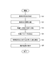
- FIG. 2 is a flowchart showing a processing flow of the analysis device of the present embodiment.
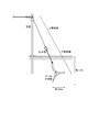
- FIG. 3 is a diagram for explaining a branch line.
- FIG. 4 is a perspective view showing the configuration of the lower anchor of the branch line.
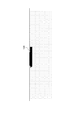
- FIG. 5 is a diagram for explaining the structure model and SPH particles used in the numerical analysis.
- FIG. 6A is a diagram showing a numerical analysis result when one row of SPH particles is placed on half of the surface of the stabilizer of the anchor under the branch line.
- FIG. 6B is a diagram showing a numerical analysis result when two rows of SPH particles are placed on half of the surface of the stabilizer of the anchor under the branch line.
- FIG. 6C is a diagram showing a numerical analysis result when three rows of SPH particles are placed on half of the surface of the stabilizer of the anchor under the branch line.
- the underground structure using a rigid material such as a steel material is handled by FEM, and the soft soil that is the support of the underground structure is smoothed-particle. It is handled by the Hydrodynamics (SPH) method.
- the soil is discretized by particles and modeled, and the SPH method is applied.
- the SPH method can simulate a continuous deformation behavior by smoothing the space around each particle by superposition of kernel functions.
- FEM underground structure
- SPH method the soil particles behave as points and the underground structure side behaves as a surface. Therefore, the particle density on the contact surface, that is, the particle diameter is an important factor in the calculation of the contact force.
- FIG. 1 is a functional block diagram showing the configuration of the analysis device 1 of the present embodiment.
- the analysis device 1 shown in the figure includes a structure model generation unit 11, a particle generation unit 12, a setting unit 13, a calculation unit 14, and a display unit 15.
- Each part included in the analysis device 1 may be configured by a computer provided with a central processing unit, a storage device, and the like, and the processing of each part may be executed by a program.
- This program is stored in a storage device included in the analysis device 1, and can be recorded on a recording medium such as a magnetic disk, an optical disk, or a semiconductor memory, or can be provided through a network.
- the structure model generation unit 11 generates a structure model (three-dimensional model) that models an underground structure by CAD.
- the structure model generation unit 11 may input a structure model generated by another device.
- the structure model generation unit 11 divides the structure model into a plurality of finite elements (mesh) used in FEM.
- the particle generation unit 12 discretizes the soil to generate modeled SPH particles and fills the periphery of the structure model. At this time, in the particle generation unit 12, the SPH particles are placed in the main contact portion between the SPH particles and the structure model so that the processing time of the calculation unit 14 described later is within a predetermined time and good analysis results can be obtained.
- the particle size of the SPH particles is set for proper contact. If the particle size of the SPH particles is small, sufficient accurate analysis results can be obtained, but the processing time increases. If the particle size of the SPH particles is large, accurate analysis results cannot be obtained. In the present embodiment, the particle generation unit 12 sets the maximum particle size that does not cause a time history result such that the pull-out resistance force of the analysis result is underestimated.
- the setting unit 13 sets various parameters required for the analysis process. For example, setting of element coordinate system, setting of material property value, setting of boundary condition, setting of external force condition, and the like can be mentioned.
- the calculation unit 14 applies the FEM and SPH methods to perform coupled analysis of the structure model and SPH particles.
- the display unit 15 displays the analysis result by the calculation unit 14.
- the display unit 15 displays the analysis result by a vector diagram, contour lines, a time history diagram, an animation, or the like.
- step S1 the structure model generation unit 11 forms a structure model of the underground structure to be analyzed.
- step S2 the structure model generation unit 11 divides the structure model into a plurality of finite elements.
- step S3 the particle generation unit 12 discretizes the soil to generate modeled SPH particles and fills the periphery of the structure model.
- step S4 the setting unit 13 sets various parameters required for analysis.
- step S5 the calculation unit 14 applies the FEM and SPH methods to perform a coupled analysis of the extraction test of the underground structure.
- step S6 the display unit 15 displays the analysis result.
- a branch line is installed on the utility pole in order to keep the force applied to the utility pole that crosses the communication cable in equilibrium.
- the branch line consists of an upper branch line (steel stranded wire) and a lower branch line.
- the lower branch line is composed of a rod portion (steel rod) that is directly connected to the upper branch line and an anchor body portion that is buried in the ground. The rod portion and the anchor body portion are fastened with bolts passed through the strap. A force is applied to the anchor body to pull it out from the rod.
- the anchor main body 100 is composed of three parts, a guide plate 110, a resistance plate 120, and a stabilizer 130.
- the guide plate 110 is connected to the rod portion.
- a steel plate called a direction plate 121 is welded to the resistance plate 120 perpendicularly to the surface direction.
- the pull-out test of the anchor under the branch line when a load was applied to the loop of the rod portion was numerically analyzed by changing the particle size of the SPH particles.
- the upper surface of the stabilizer 130 is the main contact surface with the soil when the anchor under the branch line is pulled out. Since the upper surface of the stabilizer 130 is line-symmetrical, half of the stabilizer 130 was used as the structure model.
- the width of the stabilizer 130 halved is 50 mm.
- FIG. 5 shows the position of the SPH particles when the structure model and the particle diameter of the SPH particles are 30 mm. Assuming that the particle size is 30 mm, 2 rows ⁇ 16 points of SPH particles are placed on a structure model having a width of 50 mm, and half of the soil is represented by 17 rows ⁇ 67 points of SPH particles.
- the particle spacing (distance between the center of the particles) is almost the same as the particle diameter.
- the particle spacing changes according to the particle size.
- the particle size is 50 mm or more, the number of SPH particles expressing the soil is reduced, and the number of SPH particles on the structure model is one row or less.
- the particle size is less than 30 mm, the number of SPH particles representing the soil increases, and the number of SPH particles on the structure model is three or more rows.
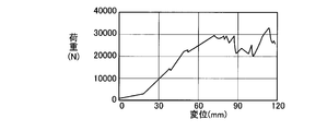
- Figures 6A to 6C show the numerical analysis results when the number of rows of SPH particles on the stabilizer 130 is changed.
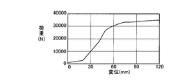
- the graphs of FIGS. 6A to 6C show the relationship with the displacement indicating the pull-out state of the anchor under the branch line due to the load when a load is applied to the loop of the rod portion.
- the graph of FIG. 6A is a numerical analysis result when one row of SPH particles is placed on the surface of the stabilizer 130.
- the particle diameter is 50 mm or more, one row or less of SHP particles are placed on the surface of the structure model of the stabilizer 130 having a width of 50 mm.
- the structure model slips between the particles, so that the pull-out resistance is significantly reduced.
- the SPH particle diameter is 50 mm, the SPH particles are placed on the surface of the structure model in only one row or less, and the particles are easily skid on the anchor surface by pulling out. For this reason, it is not possible to calculate accurately because the time history results such that the pull-out resistance is underestimated are repeatedly shown. That is, as shown in FIG. 6A, the graph showing the numerical analysis result is rattling.
- the calculation execution time by the Intel Xeon CPU 8 cores was about 25 hours.
- the graph of FIG. 6B is a numerical analysis result when two rows of SPH particles are placed on the surface of the stabilizer 130.
- the particle size is 30 mm or more and less than 50 mm, as shown in FIG. 5, two rows of SPH particles are placed on the surface of the structure model of the stabilizer 130 having a width of 50 mm.
- the calculated resistance is about the same as the nominal bearing capacity of the lower branch line anchor of 30 kN, which is relatively accurate.
- the graph showing the numerical analysis result is not loose and does not show the time history result in which the pull-out resistance is underestimated.
- the calculation execution time by the Intel Xeon CPU 8 cores was about 45 hours.
- the graph of FIG. 6C is a numerical analysis result when three rows of SPH particles are placed on the surface of the stabilizer 130.
- the particle size is less than 30 mm, three or more rows of SPH particles are placed on the surface of the structure model of the stabilizer 130 having a width of 50 mm.
- Soil modeled with SPH particles with smaller particle size has sufficient expressive power, and pull-out resistance can be calculated with sufficient accuracy.
- the amount of calculation will increase explosively. Depending on the ability of the computer, it may take an unrealistic amount of time, resulting in practical problems.
- the calculation execution time by the Intel Xeon CPU 8 cores was 125 hours or more.
- the structure model generation unit 11 generates a structure model that models the underground structure, and the particle generation unit 12 has an insufficient pull-out resistance force as a result of the analysis.
- the diameter of the maximum SPH particle that does not show the time history result to be evaluated SPH particles that model the soil that is the support of the underground structure are generated, and the calculation unit 14
- the diameter of the SPH particles that modeled the soil is set appropriately. The trade-off between model accuracy and computational volume can be resolved.
Landscapes
- Engineering & Computer Science (AREA)
- Physics & Mathematics (AREA)
- Theoretical Computer Science (AREA)
- Geometry (AREA)
- General Physics & Mathematics (AREA)
- Evolutionary Computation (AREA)
- General Engineering & Computer Science (AREA)
- Computer Hardware Design (AREA)
- Computational Mathematics (AREA)
- Mathematical Analysis (AREA)
- Mathematical Optimization (AREA)
- Pure & Applied Mathematics (AREA)
- Piles And Underground Anchors (AREA)
- Investigating Strength Of Materials By Application Of Mechanical Stress (AREA)
Abstract
地中構造体の引抜き試験を模擬する数値解析において、モデルの精度と計算量のトレードオフを解決する。構造体モデル生成部11が地中構造体をモデル化した構造体モデルを生成し、粒子生成部12が、解析の結果の引抜き抵抗力が過小評価されるような時刻歴結果を示すことが生じることのない最大のSPH粒子の径を設定して、地中構造体の支持体である土壌をモデル化したSPH粒子を生成し、演算部14が有限要素法とSPH法により構造体モデルとSPH粒子を連成解析する。
Description
本発明は、土壌に埋設された地中構造体の解析技術に関する。
電柱は、社会インフラを支える構造物の一つである。通信ケーブルを架渉する電柱にかかる力を平衡に保つため、末端の電柱には支柱もしくは支線が設置される。支線は、上部支線(鋼より線)と下部支線に分かれる。下部支線の一種である支線アンカが地中に埋め込まれて、電柱を支持する。
下部支線アンカは、地中に埋設されるため、直接劣化状態を観察することは難しい。そこで、コンピュータ援用工学(Computer Aided Engineering:CAE)における数値解析により、構造物の耐力を推定および予測することが試みられている。
Nils Karajan, Zhidong Han, Hailong Teng, Jason Wang, "On the Parameter Estimation for the Discrete-Element Method in LS-DYNA", 13th International LS-DYNA Users Conference 2014
Nils Karajan, Zhidong Han, Hailong Teng, Jason Wang, "Interaction Possibilities of Bonded and Loose Particles", 9th European LS-DYNA Conference 2013
地中構造体の引抜き試験のシミュレーションにおいて、剛な構造用鋼材を前提とした地中構造体と、それを支持する柔な粘土質・砂質土とを同時にモデル化し、一体物として連成解析を実施するには、様々な観点から困難を伴う。
地中構造体と土壌の連成問題を取り上げた場合、解析手法として、例えば、有限要素法(FEM)およびメッシュフリー法のひとつであるエレメント・フリー・ガラーキン法(EFGM)、土壌を連続体ではなく離散体として取扱う個別要素法(DEM)などが考えられる。
EFGMを用いて土壌の変形を再現するための手法を検討すると、下記の問題に突き当たる。一つめは、ある程度の引き抜き・変形には対応できるが、100mm程度の引き抜きを模擬するのが限界である点である。EFGMでは、領域積分のためのバックグラウンドメッシュ品質が重要であり、これが構造メッシュに依存する場合は極端な変形に対応することが困難であることが原因である。二つめは、重力の影響が結果に殆ど表出しない点である。EFGMを用いて計算されたアンカ引抜荷重の大部分は変形抵抗成分によって賄われている。つまり土壌の変形抵抗を過大評価している可能性がある。三つめは、柔らかい土に対しては接触不安定性によりほとんど計算ができない点である。
DEMを用いて土壌の変形を再現するための手法を検討すると、下記の問題に突き当たる。一つめは、土壌粒子間の結合強度を過小評価し過ぎる点である。二つめは、土壌粒子を粒子状離散体としてモデル化しているために、土壌分野で一般に使用されているムーアクーロンモデルなど、土壌粘性と内部摩擦などとの関連性を見出すことが困難な数値解析モデルとなってしまう点である。
土壌のモデル化において、土壌粒子の結合強度の観点などから,取り得る手法は限定されるという課題がある。また、モデルの高精細化および解析手法によっては、計算量が爆発的に増加するという課題がある。
本発明は、上記に鑑みてなされたものであり、地中構造体の引抜き試験を模擬する数値解析において、モデルの精度と計算量のトレードオフを解決することを目的とする。
本発明の一態様に係る解析装置は、地中構造体をモデル化した構造体モデルを生成する構造体モデル生成部と、前記地中構造体の支持体である土壌をモデル化した粒子を生成する粒子生成部と、有限要素法とSPH法により前記構造体モデルと前記粒子を連成解析する演算部と、を備え、前記粒子生成部は、解析の結果の引抜き抵抗力が過小評価されるような時刻歴結果を示すことが生じることのない最大の前記粒子の径を設定することを特徴とする。
本発明によれば、地中構造体の引抜き試験を模擬する数値解析において、モデルの精度と計算量のトレードオフを解決することができる。
以下、本発明の実施の形態について図面を用いて説明する。
本実施形態では、地中構造体の引抜き試験のシミュレーションにおいて、鉄鋼材料など剛な材料を使用した地中構造体をFEMにて扱い、地中構造体の支持体である柔な土壌をSmoothed Particle Hydrodynamics(SPH)法で扱う。本実施形態では、土壌を粒子で離散化してモデル化し、SPH法を適用する。SPH法は、各粒子の周囲の空間をカーネル関数の重ね合わせによってスムージングすることにより、連続体的な変形挙動を模擬できる。一方で、地中構造体(FEM)と土壌(SPH法)との接触判定において、土壌粒子は点として地中構造体側は面として振る舞う。このため、接触力の算出において、接触面上における粒子密度、すなわち粒子径は重要な要素となる。
図1は、本実施形態の解析装置1の構成を示す機能ブロック図である。同図に示す解析装置1は、構造体モデル生成部11、粒子生成部12、設定部13、演算部14、および表示部15を備える。解析装置1が備える各部は、中央演算処理装置、記憶装置等を備えたコンピュータにより構成して、各部の処理がプログラムによって実行されるものとしてもよい。このプログラムは解析装置1が備える記憶装置に記憶されており、磁気ディスク、光ディスク、半導体メモリ等の記録媒体に記録することも、ネットワークを通して提供することも可能である。
構造体モデル生成部11は、CADにより地中構造体をモデル化した構造体モデル(3次元モデル)を生成する。構造体モデル生成部11は、他の装置で生成した構造体モデルを入力してもよい。構造体モデル生成部11は、構造体モデルを、FEMで用いる複数の有限個の要素(メッシュ)に分割する。
粒子生成部12は、土壌を離散化してモデル化したSPH粒子を生成し、構造体モデルの周囲に充溢させる。このとき、粒子生成部12は、後述の演算部14の処理時間が所定時間内に収まり、かつ、良好な解析結果が得られるよう、SPH粒子と構造体モデルとの主たる接触部分にSPH粒子が適切に接触するように、SPH粒子の粒子径を設定する。SPH粒子の粒子径が小さいと十分な精度の解析結果が得られるが、処理時間が増大する。SPH粒子の粒子径が大きいと正確な解析結果が得られない。本実施形態では、粒子生成部12は、解析の結果の引抜き抵抗力が過小評価されるような時刻歴結果を示すことが生じることのない最大の粒子径を設定する。
設定部13は、解析処理に必要な各種パラメータの設定を行う。例えば、要素座標系の設定、材料特性値の設定、境界条件の設定、および外力条件の設定などが挙げられる。
演算部14は、FEMとSPH法を適用して、構造体モデルとSPH粒子を連成解析する。
表示部15は、演算部14による解析結果を表示する。例えば、表示部15は、ベクトル図、等高線、時刻歴図、アニメーションなどにより解析結果を表示する。
図2を参照し、本実施形態の解析装置1の動作について説明する。
ステップS1において、構造体モデル生成部11は、解析対象の地中構造体の構造体モデルを形成する。
ステップS2において、構造体モデル生成部11は、構造体モデルを複数の有限個の要素に分割する。
ステップS3において、粒子生成部12は、土壌を離散化してモデル化したSPH粒子を生成し、構造体モデルの周囲に充溢させる。
ステップS4において、設定部13は、解析に必要な各種パラメータを設定する。
ステップS5において、演算部14は、FEMとSPH法を適用して、地中構造体の引抜き試験の連成解析を行う。
ステップS6において、表示部15は、解析結果を表示する。
次に、本実施形態の解析装置1により、支線下部アンカの引抜き試験を数値解析した実施例について説明する。
図3に示すように、通信ケーブルを架渉する電柱にかかる力を平衡に保つために、支線を電柱に設置する。支線は、上部支線(鋼より線)と下部支線で構成される。下部支線は、上部支線と直接繋がるロッド部(鋼棒)と地中に埋設されるアンカ本体部で構成される。ロッド部とアンカ本体部とは、ストラップに通したボルトで締結される。アンカ本体部には、ロッド部から引き抜く力が加えられる。
図4に示すように、アンカ本体部100は、案内板110、抵抗板120、および安定板130の3つの部分からなる。案内板110はロッド部に接続される。抵抗板120は、面方向に対して垂直に方向板121と呼ばれる鋼板が溶接される。抵抗板120の安定板130側には、安定板受122と呼ばれる三角形状の突起台座(鋼板)が存在する。
解析装置1を用いて、ロッド部のループに荷重をかけたときの支線下部アンカの引抜き試験をSPH粒子の粒子径を変えて数値解析した。
安定板130の上面は、支線下部アンカを引抜くときの土壌との主たる接触面となる。安定板130の上面が線対称であることから、構造体モデルとして安定板130の半分を用いた。半分にした安定板130の幅は50mmである。
半分の安定板130の引抜き試験に伴い影響を受けると予想される土壌をモデル化した。図5に、構造体モデルとSPH粒子の粒子径を30mmとしたときのSPH粒子の位置を示す。粒子径を30mmとすると、幅50mmの構造体モデル上に2列×16点のSPH粒子が乗り、土壌半分が17列×67点のSPH粒子で表現されている。
粒子の間隔(粒子の中心間の距離)は、ほぼ粒子径と同じである。粒子径に応じて粒子の間隔が変わる。粒子径を50mm以上とすると、土壌を表現するSPH粒子の数は減り、構造体モデル上に乗るSPH粒子は1列以下となる。粒子径を30mm未満とすると、土壌を表現するSPH粒子の数は増え、構造体モデル上に乗るSPH粒子は3列以上となる。
図6A~6Cに、安定板130上に乗るSPH粒子の列の数を変更した場合の数値解析結果を示す。図6A~6Cのグラフは、ロッド部のループに荷重をかけたときの、その荷重による支線下部アンカの引抜け状況を示す変位との関係を示す。
図6Aのグラフは、安定板130表面上にSPH粒子が1列乗った場合の数値解析結果である。粒子径を50mm以上とした場合、幅が50mmの安定板130の構造体モデルの表面にはSHP粒子が1列以下乗る。SPH粒子径が構造体モデルの幅よりも広い場合、粒子間を構造体モデルがすり抜けるために引き抜き抵抗力が大幅に低下する。SPH粒子径が50mmの場合、SPH粒子が構造体モデルの表面に1列以下しか乗らず、引抜きによりアンカ面上での粒子の横滑りが容易に起きる。このため、引抜き抵抗力が過小評価されるような時刻歴結果を示すことが繰り返し生じ正確に計算できない。すなわち、図6Aに示すように、数値解析結果を示すグラフがガタついてしまう。なお、Intel Xeon CPU 8コアによる計算実行時間は約25時間であった。
図6Bのグラフは、安定板130表面上にSPH粒子が2列乗った場合の数値解析結果である。粒子径を30mm以上50mm未満とした場合、図5に示したように、幅が50mmの安定板130の構造体モデルの表面にはSPH粒子が2列乗る。安定板130の構造体モデルの表面にSPH粒子が2列乗るとき、計算した抵抗力は、下部支線アンカの公称地耐力30kNと同程度になり、比較的正確である。図6Bに示すように、数値解析結果を示すグラフはガタついておらず、引抜き抵抗力が過少評価されるような時刻歴結果を示していない。なお、Intel Xeon CPU 8コアによる計算実行時間は約45時間であった。
図6Cのグラフは、安定板130表面上にSPH粒子が3列乗った場合の数値解析結果である。粒子径を30mm未満とした場合、幅が50mmの安定板130の構造体モデルの表面にはSPH粒子が3列以上乗る。より粒子径の小さいSPH粒子でモデル化した土壌は十分な表現力を有しており、引抜き抵抗力は十分な精度をもって計算され得る。しかしながら、土壌半分が図5よりも多数のSPH粒子で表現されるので、計算量は爆発的に増加することとなる。計算機の能力によっては、非現実的な時間を要することとなり、実用上問題を来す結果となる。なお、Intel Xeon CPU 8コアによる計算実行時間は125時間以上であった。
以上説明したように、本実施形態によれば、構造体モデル生成部11が地中構造体をモデル化した構造体モデルを生成し、粒子生成部12が、解析の結果の引抜き抵抗力が過小評価されるような時刻歴結果を示すことが生じることのない最大のSPH粒子の径を設定して、地中構造体の支持体である土壌をモデル化したSPH粒子を生成し、演算部14が有限要素法とSPH法により構造体モデルとSPH粒子を連成解析することにより、地中構造体の引抜き試験を模擬する数値解析において、土壌をモデル化したSPH粒子の径を適切に設定してモデルの精度と計算量のトレードオフを解決できる。
1…解析装置
11…構造体モデル生成部
12…粒子生成部
13…設定部
14…演算部
15…表示部
100…アンカ本体部
110…案内板
120…抵抗板
121…方向板
122…安定板受
130…安定板
11…構造体モデル生成部
12…粒子生成部
13…設定部
14…演算部
15…表示部
100…アンカ本体部
110…案内板
120…抵抗板
121…方向板
122…安定板受
130…安定板
Claims (2)
- 地中構造体をモデル化した構造体モデルを生成する構造体モデル生成部と、
前記地中構造体の支持体である土壌をモデル化した粒子を生成する粒子生成部と、
有限要素法とSPH法により前記構造体モデルと前記粒子を連成解析する演算部と、を備え、
前記粒子生成部は、解析の結果の引抜き抵抗力が過小評価されるような時刻歴結果を示すことが生じることのない最大の前記粒子の径を設定する
ことを特徴とする解析装置。 - 前記地中構造体は下部支線アンカであり、
前記粒子生成部は、前記粒子と前記構造体モデルとの主たる接触部分において前記粒子が前記構造体モデルに2列接触するように前記粒子の径を設定する
ことを特徴とする請求項1に記載の解析装置。
Priority Applications (1)
| Application Number | Priority Date | Filing Date | Title |
|---|---|---|---|
| US17/617,539 US20220245289A1 (en) | 2019-06-17 | 2020-06-03 | Analyzer |
Applications Claiming Priority (2)
| Application Number | Priority Date | Filing Date | Title |
|---|---|---|---|
| JP2019111836A JP7148806B2 (ja) | 2019-06-17 | 2019-06-17 | 解析装置 |
| JP2019-111836 | 2019-06-17 |
Publications (1)
| Publication Number | Publication Date |
|---|---|
| WO2020255709A1 true WO2020255709A1 (ja) | 2020-12-24 |
Family
ID=73837430
Family Applications (1)
| Application Number | Title | Priority Date | Filing Date |
|---|---|---|---|
| PCT/JP2020/021868 Ceased WO2020255709A1 (ja) | 2019-06-17 | 2020-06-03 | 解析装置 |
Country Status (3)
| Country | Link |
|---|---|
| US (1) | US20220245289A1 (ja) |
| JP (1) | JP7148806B2 (ja) |
| WO (1) | WO2020255709A1 (ja) |
Cited By (1)
| Publication number | Priority date | Publication date | Assignee | Title |
|---|---|---|---|---|
| CN112597690A (zh) * | 2021-03-08 | 2021-04-02 | 四川轻化工大学 | 基于sph的燃气管道受挖掘施工破坏过程的分析方法 |
Families Citing this family (2)
| Publication number | Priority date | Publication date | Assignee | Title |
|---|---|---|---|---|
| CN113089636B (zh) * | 2021-04-25 | 2022-03-25 | 中铁二院工程集团有限责任公司 | 一种膨胀土地基路堤桩板墙的加固桩设计方法 |
| CN114624039B (zh) * | 2022-01-21 | 2023-10-20 | 石家庄铁道大学 | 模拟地下工程结构开口破除的模型试验方法及装置 |
Citations (4)
| Publication number | Priority date | Publication date | Assignee | Title |
|---|---|---|---|---|
| JP2003262580A (ja) * | 2002-03-08 | 2003-09-19 | Nippon Telegraph & Telephone East Corp | 地中埋設物の腐食診断方法、腐食診断プログラム、腐食診断プログラムを記録した記録媒体、および腐食診断装置 |
| JP2017003558A (ja) * | 2015-06-10 | 2017-01-05 | 日本電信電話株式会社 | 推定方法 |
| JP2017134479A (ja) * | 2016-01-26 | 2017-08-03 | ジヤトコ株式会社 | 流体解析装置、流体解析方法及び流体解析プログラム |
| JP2018205260A (ja) * | 2017-06-09 | 2018-12-27 | 日本電信電話株式会社 | 劣化判定方法及び劣化判定装置 |
-
2019
- 2019-06-17 JP JP2019111836A patent/JP7148806B2/ja active Active
-
2020
- 2020-06-03 US US17/617,539 patent/US20220245289A1/en not_active Abandoned
- 2020-06-03 WO PCT/JP2020/021868 patent/WO2020255709A1/ja not_active Ceased
Patent Citations (4)
| Publication number | Priority date | Publication date | Assignee | Title |
|---|---|---|---|---|
| JP2003262580A (ja) * | 2002-03-08 | 2003-09-19 | Nippon Telegraph & Telephone East Corp | 地中埋設物の腐食診断方法、腐食診断プログラム、腐食診断プログラムを記録した記録媒体、および腐食診断装置 |
| JP2017003558A (ja) * | 2015-06-10 | 2017-01-05 | 日本電信電話株式会社 | 推定方法 |
| JP2017134479A (ja) * | 2016-01-26 | 2017-08-03 | ジヤトコ株式会社 | 流体解析装置、流体解析方法及び流体解析プログラム |
| JP2018205260A (ja) * | 2017-06-09 | 2018-12-27 | 日本電信電話株式会社 | 劣化判定方法及び劣化判定装置 |
Cited By (1)
| Publication number | Priority date | Publication date | Assignee | Title |
|---|---|---|---|---|
| CN112597690A (zh) * | 2021-03-08 | 2021-04-02 | 四川轻化工大学 | 基于sph的燃气管道受挖掘施工破坏过程的分析方法 |
Also Published As
| Publication number | Publication date |
|---|---|
| US20220245289A1 (en) | 2022-08-04 |
| JP2020204867A (ja) | 2020-12-24 |
| JP7148806B2 (ja) | 2022-10-06 |
Similar Documents
| Publication | Publication Date | Title |
|---|---|---|
| Shahir et al. | Employing a variable permeability model in numerical simulation of saturated sand behavior under earthquake loading | |
| WO2020255709A1 (ja) | 解析装置 | |
| CN109684785A (zh) | 一种深部高应力巷道围岩动态损伤破坏演化方法及系统 | |
| AU2012327124B2 (en) | Analysis device, analysis method, analysis program, and recording medium | |
| Nagula et al. | Coupled Eulerian Lagrangian based numerical modelling of vibro-compaction with model vibrator | |
| Amouzgar et al. | Computationally efficient tsunami modeling on graphics processing units (GPUs) | |
| CN118332653B (zh) | 一种爆破荷载下隧道洞门结构动力响应计算方法和系统 | |
| Naeij et al. | Explicit finite element analysis of slope stability by strength reduction | |
| CN118709485A (zh) | 一种基于dem-fem耦合的土质隧道开挖数值模拟方法 | |
| Nagula et al. | Numerical investigation of liquefaction mitigation potential with vibroflotation | |
| CN118114515A (zh) | 一种综合震后机制模型建立方法、系统、设备及存储介质 | |
| Ceccato et al. | Developing and testing multiphase MPM approaches for the stability of dams and river embankments | |
| Ceccato et al. | The effect of the front inclination on the impact forces transmitted by granular flows to rigid structures | |
| EP1696356A1 (en) | Flow acoustic simulation with the Lattice-Boltzmann method | |
| Yuan et al. | Distributions of strong ground motion due to dynamic ruptures across a bimaterial fault: Implications for seismic hazard analyses | |
| CN118311227B (zh) | 采用临界状态亚塑性模型的土体变形模拟方法及系统 | |
| Kaoua et al. | Finite element simulation of mechanical behaviour of nickel-based metallic foam structures | |
| Ando et al. | An efficient boundary integral equation method applicable to the analysis of non-planar fault dynamics | |
| CN116882001A (zh) | 一种路堑边坡地震稳定性数值模拟方法 | |
| Wang et al. | LEAP-UCD-2017 simulations at Tsinghua University | |
| US11188690B1 (en) | Systems and methods for performing thermal simulation of an additive manufacturing process | |
| Huang et al. | Numerical simulation of drag anchor trajectory in non-linear soil based on cel method | |
| Wang et al. | Engineering evaluation of deterministic ground-motion simulation based on the dynamic response of Pine Flat dam | |
| Sun et al. | Evolution of the soil dynamic response during the vibratory pile driving based on an integrated MPM–FEM method | |
| CN119167733B (zh) | 地震诱发边坡位移预测方法、装置、设备、介质及产品 |
Legal Events
| Date | Code | Title | Description |
|---|---|---|---|
| 121 | Ep: the epo has been informed by wipo that ep was designated in this application |
Ref document number: 20825672 Country of ref document: EP Kind code of ref document: A1 |
|
| NENP | Non-entry into the national phase |
Ref country code: DE |
|
| 122 | Ep: pct application non-entry in european phase |
Ref document number: 20825672 Country of ref document: EP Kind code of ref document: A1 |