WO2020255654A1 - Communication device and communication method - Google Patents
Communication device and communication method Download PDFInfo
- Publication number
- WO2020255654A1 WO2020255654A1 PCT/JP2020/020950 JP2020020950W WO2020255654A1 WO 2020255654 A1 WO2020255654 A1 WO 2020255654A1 JP 2020020950 W JP2020020950 W JP 2020020950W WO 2020255654 A1 WO2020255654 A1 WO 2020255654A1
- Authority
- WO
- WIPO (PCT)
- Prior art keywords
- qos
- communication
- quality
- communication device
- requirement
- Prior art date
Links
Images


Classifications
-
- H—ELECTRICITY
- H04—ELECTRIC COMMUNICATION TECHNIQUE
- H04W—WIRELESS COMMUNICATION NETWORKS
- H04W28/00—Network traffic management; Network resource management
- H04W28/02—Traffic management, e.g. flow control or congestion control
- H04W28/0247—Traffic management, e.g. flow control or congestion control based on conditions of the access network or the infrastructure network
-
- H—ELECTRICITY
- H04—ELECTRIC COMMUNICATION TECHNIQUE
- H04W—WIRELESS COMMUNICATION NETWORKS
- H04W28/00—Network traffic management; Network resource management
- H04W28/02—Traffic management, e.g. flow control or congestion control
- H04W28/0268—Traffic management, e.g. flow control or congestion control using specific QoS parameters for wireless networks, e.g. QoS class identifier [QCI] or guaranteed bit rate [GBR]
-
- H—ELECTRICITY
- H04—ELECTRIC COMMUNICATION TECHNIQUE
- H04W—WIRELESS COMMUNICATION NETWORKS
- H04W64/00—Locating users or terminals or network equipment for network management purposes, e.g. mobility management
-
- H—ELECTRICITY
- H04—ELECTRIC COMMUNICATION TECHNIQUE
- H04W—WIRELESS COMMUNICATION NETWORKS
- H04W28/00—Network traffic management; Network resource management
- H04W28/16—Central resource management; Negotiation of resources or communication parameters, e.g. negotiating bandwidth or QoS [Quality of Service]
- H04W28/24—Negotiating SLA [Service Level Agreement]; Negotiating QoS [Quality of Service]
Definitions
- the present invention relates to a communication device and a communication method in a wireless communication system.
- 5G or NR New Radio
- 5G wireless communication system
- 5G various wireless technologies are being studied in order to satisfy the requirement that the delay of the wireless section be 1 ms or less while achieving a throughput of 10 Gbps or more.
- 5GC 5G Core Network
- EPC Evolved Packet Core
- RAN Radio Access Network
- a network architecture including NG-RAN (Next Generation-Radio Access Network) corresponding to Evolved Universal Terrestrial Radio Access Network) is being studied (for example, Non-Patent Document 1).
- the present invention has been made in view of the above points, and an object of the present invention is to execute communication provided by QoS (Quality of Service) in a wireless network according to a situation.
- QoS Quality of Service
- QoS Quality of Service
- wireless communication is executed in which QoS is not provided, and when the control unit sets the requirement in QoS, the QoS to which the requirement is set is provided.
- a communication device having a communication unit that executes wireless communication is provided.
- QoS Quality of Service
- LTE Long Term Evolution
- NR NR
- LAN Local Area Network
- “configuring" the radio parameter or the like may mean that a predetermined value is set in advance (Pre-configure), or the network node 10 or The radio parameter notified from the user device 20 may be set.
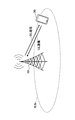
- FIG. 1 is a diagram for explaining a wireless network according to an embodiment of the present invention.
- a system including a wireless network according to an embodiment of the present invention includes a base station device 10 and a user device 20 as shown in FIG. Although FIG. 1 shows one base station device 10 and one user device 20, this is an example, and there may be a plurality of each.
- the base station device 10 may be referred to as a network node 10.
- the base station device 10 is a communication device that provides one or more cells and performs wireless communication with the user device 20.
- the physical resources of the radio signal are defined in the time domain and the frequency domain, the time domain may be defined by the number of OFDM symbols, and the frequency domain may be defined by the number of subcarriers or the number of resource blocks.
- the base station apparatus 10 transmits a synchronization signal and system information to the user apparatus 20.
- the synchronization signals are, for example, NR-PSS (PrimarySynchronizationSignal) and NR-SSS (SecondarySynchronizationSignal).
- the system information is transmitted by, for example, NR-PBCH (Physical Broadcast Channel), and is also referred to as broadcast information. As shown in FIG.
- the base station apparatus 10 transmits a control signal or data to the user apparatus 20 by DL (Downlink), and receives the control signal or data from the user apparatus 20 by UL (Uplink). Both the base station device 10 and the user device 20 can perform beamforming to transmit and receive signals. Further, both the base station device 10 and the user device 20 can apply MIMO (Multiple Input Multiple Output) communication to DL or UL. Further, both the base station device 10 and the user device 20 may communicate via SCell (Secondary Cell) and PCell (Primary Cell) by CA (Carrier Aggregation).
- SCell Secondary Cell
- PCell Primary Cell
- the user device 20 is a communication device having a wireless communication function such as a smartphone, a mobile phone, a tablet, a wearable terminal, and a communication module for M2M (Machine-to-Machine).
- the user apparatus 20 is provided by a wireless communication system by receiving a control signal or data from the base station apparatus 10 in DL and transmitting the control signal or data to the base station apparatus 10 in UL.
- the user device 20 may have a function as a client application that communicates with an application server arranged in the network.
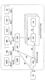
- FIG. 2 is a diagram for explaining a core network according to an embodiment of the present invention.
- the system including the core network according to the embodiment of the present invention is composed of a UE which is a user device 20 and a plurality of network nodes 10.
- a UE which is a user device 20
- a plurality of network nodes 10 10
- one network node 10 corresponds to each function, but one network node 10 may realize a plurality of functions, or a plurality of network nodes 10 may realize one function. ..
- the "connection" described below may be a logical connection or a physical connection.
- the RAN Radio Access Network
- the RAN Radio Access Network
- the base station device 10 may be a network node 10 corresponding to RAN.
- the AMF is a network node 10 having functions such as RAN interface termination, NAS (Non-Access Stratum) termination, registration management, connection management, reachability management, and mobility management.
- the UPF is a network node 10 having functions such as a PDU (Protocol Data Unit) session point to the outside interconnected with a DN (Data Network), packet routing and forwarding, and user plane QoS (Quality of Service) handling.
- UPF and DN constitute a network slice.
- a plurality of network slices are constructed.
- AMF includes UE, RAN, SMF (Session Management function), NSSF (Network Slice Selection Function), NEF (Network Exposure Function), NRF (Network Repository Function), UDM (Unified Data Management), AUSF (Authentication Server Function), It is connected to PCF (Policy Control Function) and AF (Application Function).
- AMF, SMF, NSSF, NEF, NRF, AUSF, PCF, AF are networks connected to each other via their respective service-based interfaces, Namf, Nsmf, Nnssf, Nnef, Nnrf, Nodem, Nausf, Npcf, Naf. Node 10
- the SMF is a network node 10 having functions such as session management, UE IP (Internet Protocol) address allocation and management, DHCP (Dynamic Host Configuration Protocol) function, ARP (Address Resolution Protocol) proxy, and roaming function.
- the NEF is a network node 10 having a function of notifying other NFs (Network Functions) of capabilities and events.
- the NSSF is a network node 10 having functions such as selecting a network slice to be connected to the UE, determining an allowed NSSAI (Network Slice Selection Assistance Information), determining an NSSAI to be set, and determining an AMF set to be connected to the UE. is there.
- the PCF is a network node 10 having a function of controlling network policy.
- AF is a network node 10 having a function of controlling an application server.
- the NRF is a network node 10 having a function of discovering an NF instance that provides a service.
- NaaS Network as a Service
- a LAN Local Area Network
- WAN Wide Area Network
- VPN Virtualization technology
- it is a service that provides a bandwidth guarantee type line service to general users, and may include construction work. 4) A service that provides the above 3) to general users on demand.
- An embodiment of the present invention relates to a technique for realizing NaaS of 4) above in a wireless network.
- NaaS in a wired network in addition to the peak rate and failure rate, items such as the form of bandwidth guarantee classified into QoS and the delay time are defined as SLA (Service Level Agreement).
- Examples of quality items that can be provided by the SLA are, for example, 1) -9) below.
- SLA is defined in advance and the response in case of violation is clarified. For example, if the average delay time exceeds Ymsec, an arrangement is made such as reducing the charge by Z%. 1) Traffic related (average throughput, delay time, packet loss rate, etc.) 2) Operation rate / availability 3) Failure notification 4) Number of simultaneous connections 5) Backup-related (frequency, items, storage period, etc.) 6) Log related (frequency, items, storage period, etc.) 7) Contact system for support desks, etc. 8) Failure-related (recovery time, response time, availability of on-site response, etc.) 9) Types of quality levels above
- Table 1 is an example of a function similar to QoS as an EPC (Evolved Packet Core) function assuming a voice call or the like in LTE.
- EPC Evolved Packet Core
- QCI QoS Class Identifier
- the bit rate is guaranteed (Guarantee), priority, delay budget (Delay Budget), packet loss rate (Loss rate), or application.
- the bit rate is guaranteed (GBR: Guaranteed bit rate)
- the priority is 3
- the permissible delay is 50 ms
- the packet loss rate is 10-3
- the application is a real-time game. ..
- the base station apparatus 10 performs scheduling and the like, and communication is performed so as to satisfy the parameters shown in Table 1.
- QoS is not guaranteed in actual communication.
- a specific usage pattern is provided in advance. It is expected to declare.
- the definition of QoS is proposed assuming an operation mode in which QoS control can be applied to a user terminal as described above.
- the geographical location may be defined by assuming a specific level of communication quality, or a specific geographical location may be assumed due to the communication quality.
- QoS branching conditions Conditions for determining whether or not to provide QoS or the degree of communication quality provided by QoS are defined (hereinafter, the conditions are referred to as "QoS branching conditions"), and the quality provided by different QoS for each QoS branching condition is defined.
- QoS requirements The requirements to be specified (hereinafter referred to as "QoS requirements") are specified.
- the determination of the QoS branching condition may be executed based on the communication state measured by the user terminal or the base station device, or may be executed based on the information or state held by the client application or application server. Alternatively, it may be executed based on a combination thereof.
- the same user terminal may simultaneously determine a plurality of QoS branching conditions composed of each application, each communication port, each destination or source IP address, and the like.
- the client application may be an application running on the user apparatus 20, and the application server may be a server connected to the DN shown in FIG. 2 or AF.
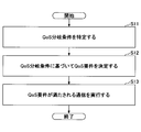
- FIG. 3 is a flowchart for explaining an example (1) of communication to which QoS is applied according to the embodiment of the present invention.
- a communication in which a QoS requirement is determined based on a QoS branching condition will be described with reference to FIG.
- step S11 the user device 20 or the base station device 10 specifies a QoS branching condition.
- the QoS branching conditions may be predetermined or may be set at any time.
- step S12 the user device 20 or the base station device 10 determines the QoS requirement based on the QoS branching condition. Details of the method of determining the QoS requirement from the QoS branching condition will be described later.
- step S13 the user device 20 or the base station device 10 executes communication that satisfies the QoS requirement.
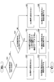
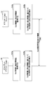
- FIG. 4 is a flowchart for explaining an example (2) of communication to which QoS is applied according to the embodiment of the present invention.
- the QoS branching condition is the RRC state of the radio section, and the QoS requirement may be determined for each RRC state.
- the flowchart shown in FIG. 4 describes a case where the user apparatus 20 executes the flowchart, but the base station apparatus 10 may execute the flowchart instead of the user apparatus 20.
- step S21 the user device 20 determines whether the RRC state, which is the QoS branching condition # 1, is "IDLE mode". When the RRC state is "IDLE mode" (YES in S21), the process proceeds to step S22, and when the RRC state is not "IDLE mode” (NO in S21), the process proceeds to step S24. In step S22, the user device 20 does not set the QoS requirement and proceeds to step S23. In step S23, the user device 20 executes communication for which the QoS requirement is not set.
- step S24 the user device 20 determines whether the RRC state, which is the QoS branching condition # 2, is "CONNECTED mode". If the RRC state is "CONCEPTED mode” (YES in S24), the process proceeds to step S25, and if the RRC state is not "CONNECTED mode” (NO in S24), the process proceeds to step S27.
- step S25 the user apparatus 20 sets U-plane delay X2 ms, C-plane delay Y2 ms, and minimum throughput Z2 Mbps as QoS requirements, and proceeds to step S26.
- step S26 the user device 20 executes communication for which the QoS requirement is set.
- step S27 the user device 20 does not set the QoS requirement and proceeds to step S28.
- step S28 the user device 20 executes communication for which the QoS requirement is not set.
- FIG. 5 is a flowchart for explaining an example (3) of communication to which QoS is applied according to the embodiment of the present invention.
- the QoS branching condition may be a condition that combines the RRC state of the radio section and the communication quality measured by the user terminal.
- the flowchart shown in FIG. 5 describes a case where the user apparatus 20 executes the flowchart, but the base station apparatus 10 may execute the flowchart instead of the user apparatus 20.
- step S31 the user device 20 determines whether the RRC state, which is the QoS branching condition # 1, is "IDLE mode". When the RRC state is "IDLE mode" (YES in S31), the process proceeds to step S32, and when the RRC state is not "IDLE mode” (NO in S31), the process proceeds to step S34. In step S32, the user device 20 does not set the QoS requirement and proceeds to step S33. In step S33, the user device 20 executes communication for which the QoS requirement is not set.
- step S34 the user apparatus 20 determines whether the RRC state, which is the QoS branching condition # 2, is "CONNECTED mode", and the measured RSRP (Reference Signals Received Power) is equal to or higher than the predetermined threshold value W2. To do.
- the RRC state is "CONNECTED mode” and the RSRP is equal to or higher than the predetermined threshold value W2 (YES in S34)
- the process proceeds to step S35, and the RRC state is not "CONCEPTED mode” or the RSRP is not equal to or higher than the predetermined threshold value W2 (YES in S34). NO of S34)
- the process proceeds to step S37.
- step S35 the user apparatus 20 sets the U-plane delay X2 ms, the C-plane delay Y2 ms, and the minimum throughput Z2 Mbps as the QoS requirement # 1, and proceeds to step S36.
- step S36 the user device 20 executes the communication for which the QoS requirement # 1 is set.
- step S37 the user apparatus 20 determines whether the RRC state, which is the QoS branching condition # 3, is "CONNECTED mode", and the measured RSRP is equal to or higher than the predetermined threshold value W3.
- step S40 When the RRC state is "CONNECTED mode” and RSRP is equal to or higher than the predetermined threshold value W3 (YES in S37), the process proceeds to step S38, and when the RRC state is not "CONNECTED mode” or RSRP is not equal to or higher than the predetermined threshold value W3 (YES in S37). NO of S37) Proceed to step S40.
- step S38 the user apparatus 20 sets the U-plane delay X3 ms, the C-plane delay Y3 ms, and the minimum throughput Z3 Mbps as the QoS requirement # 2, and proceeds to step S39.
- step S39 the user device 20 executes the communication for which the QoS requirement # 2 is set.
- step S40 the user device 20 does not set the QoS requirement and proceeds to step S41.
- step S41 the user device 20 executes communication for which the QoS requirement is not set.
- W2 may be larger than W3.
- the QoS branching condition may be configured by combining a condition relating to specific network information and a condition relating to information of a radio section.
- the specific network information may be, for example, the destination IP address of the packet.
- the information in the radio section may be, for example, the RRC state or the measured communication quality.
- the QoS branching condition may be defined by a condition composed of any of the following 1) -10), or may be defined by a condition composed of any combination of the following 1) -10).
- Good. 1) Application type or service classification (for example, VoIP (Voice over Internet Protocol), real-time games, etc.) 2) Destination IP address or source IP address of the packet 3) Communication port 4) RRC status 5) Radio quality measured by the user (for example, RSRP, RSRQ (Reference Signal Received Quality), etc.) 6) The state of the terminal other than the wireless quality measured by the user (for example, the moving state of the terminal measured by the acceleration sensor, the gyro sensor, etc.) 7) Average throughput, delay time, delay fluctuation (Jitter) or packet loss rate 8) Presence / absence of QoS control request of client application 9) Presence / absence of QoS control request of application server 10) RAT (Radio Access Technology) in the area Type
- the QoS requirement may be defined in which the radio quality is higher in the high radio quality state than in the low radio quality state.
- the QoS branching condition is defined by the moving state of the terminal, the QoS requirement that the quality of the state of moving at high speed is lower than that of the state of moving at low speed may be specified.
- the QoS requirement defined by the QoS branching condition may be defined by any of the following 1) -9), or may be defined by any combination of the following 1) -9).
- Traffic-related parameters eg, throughput, delay time, delay fluctuation, packet loss rate, etc.
- Uptime or availability 3) Failure notification 4) Number of simultaneous connections 5) Backup-related parameters (eg frequency, items, retention period, etc.) 6)
- Log-related parameters eg frequency, items, shelf life, etc.
- Service system such as support desk 8) Matters related to response to failures (for example, recovery time, response time, availability of on-site response, etc.) 9) Multiple types indicating the quality level of 1) -8) above
- a determination related to the QoS requirement may be performed, and information indicating information indicating whether or not QoS is possible related to the determination result may be notified.
- a client application running on the user device 20, an application server 10 that provides a service, an application server 10 having a QoS control function, or another network node 10 notifies information indicating whether or not the QoS can be provided in one direction or both directions. You may.
- the client application running on the user apparatus 20, the application server 10 that provides the service, the application server 10 having the function of QoS control, or the application interface called by the other network node 10 notifies the information indicating whether or not the QoS can be provided. May be specified.
- the notification regarding the availability of QoS information may include a method of determining QoS requirements.
- the QoS control is temporarily stopped or suspended.
- the client application 20 or the application server 10 may notify the other communication partner of the service as information indicating whether or not QoS can be provided.
- Various information related to QoS control may be any of the following 1) -4).
- the operation related to the notification of information indicating whether or not QoS can be provided may be changed based on any of the following 1) -6).
- the determination regarding the QoS requirement of various information related to the QoS control may be changed based on any of the following 1) -6).
- 1) Application type or service classification eg, VoIP, real-time games, etc.
- 2) Packet destination IP address or source IP address e.g., IP address or source IP address
- Communication port 4) Presence / absence of QoS control request of client application 5) Presence / absence of QoS control request of application server 6) RAT type in the area
- FIG. 6 is a sequence diagram for explaining an example of notification relating to QoS in the embodiment of the present invention.
- a sequence in which a determination related to a QoS requirement is performed based on various information related to QoS control and information indicating whether or not to provide QoS related to the determination result is notified will be described.
- step S41a the client application 20 acquires information related to QoS control. Subsequently, the client application 20 executes the determination related to the QoS requirement based on the information related to the QoS control (S42a). Subsequently, the client application 20 transmits information indicating whether or not to provide QoS based on the result of the determination to the application server 10 (S43). That is, the determination relating to the QoS requirement is a determination for determining whether or not to transmit information indicating whether or not to provide QoS. On the other hand, in step S41b, the application server 10 acquires information related to QoS control.
- the application server 10 executes the determination related to the QoS requirement based on the information related to the QoS control (S42b). Subsequently, the application server 10 transmits information indicating whether or not to provide QoS based on the result of the determination to the client application 20 (S43). That is, the determination relating to the QoS requirement is a determination for determining whether or not to transmit information indicating whether or not to provide QoS. Either the client application 20 or the application server 10 may transmit information indicating whether or not QoS can be provided in step S43.
- the client application 20 or the application server 10 may perform control related to QoS based on the received information indicating whether or not to provide QoS, and execute communication to which the control related to QoS is applied.
- the control related to QoS may be to change the QoS requirements or to switch whether or not to provide QoS.
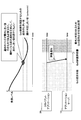
- FIG. 7 is a diagram for explaining an example of notification relating to QoS in the embodiment of the present invention. With reference to FIG. 7, an example will be described in which a determination regarding a QoS requirement is performed based on various information related to QoS control, and information indicating whether or not to provide QoS related to the determination result is notified.
- the application server 10 is a device that provides QoS.
- the client application 20 measures the reception level (for example, RSRP) as the information related to QoS control, and the reception level higher than the threshold value (qrxlevmin) used for the out-of-service judgment as the judgment related to the QoS requirement.
- the reception level is compared with the additional threshold to guarantee the QoS control corresponding to. If the reception level falls below the additional threshold, a "failure notification" may be sent to the application server 10. That is, control may be performed in which the QoS is provided at the time before the "failure notification" and the QoS is not provided at the time of the "failure notification". If the reception level drops further after the "fault notification", the service will be out of service and QoS provision will be impossible.
- RSRP reception level
- qrxlevmin threshold value
- the additional threshold value used for the determination related to the QoS requirement may be the same value as the threshold value used for the out-of-service determination, or may be a different value. Further, the additional threshold value used for the determination related to the QoS requirement may be the same value as the threshold value used for the determination of the QoS branching condition shown in FIG. 5, or may be a different value.
- the "failure notification" may include information indicating that the information related to the guaranteeable QoS control has changed.
- the application server 10 that has received the information indicating that the information relating to the guaranteeable QoS control has changed may change the QoS requirement based on the information indicating that the guaranteeable QoS requirement has changed.
- the client application 20 when the reception level improves, the client application 20 returns to the state where the QoS can be provided when it detects that the reception level has returned to a sufficient quality.
- a notification indicating that this has been done may be sent to the application server 10.
- the application server 10 may request the client application 20 to report information indicating whether or not QoS can be provided or information necessary for determining whether or not QoS can be provided.
- the network node 10 or the user apparatus 20 defines a QoS branching condition, that is, a condition for determining whether or not to provide QoS or the degree of communication quality provided by QoS, and based on the condition, the QoS Can determine the requirements that define the quality provided by.
- a QoS branching condition that is, a condition for determining whether or not to provide QoS or the degree of communication quality provided by QoS, and based on the condition, the QoS Can determine the requirements that define the quality provided by.
- QoS Quality of Service
- the network node 10 and the user apparatus 20 include a function of carrying out the above-described embodiment.
- the network node 10 and the user device 20 may each have only a part of the functions in the embodiment.
- FIG. 8 is a diagram showing an example of the functional configuration of the network node 10.
- the network node 10 has a transmission unit 110, a reception unit 120, a setting unit 130, and a control unit 140.
- the functional configuration shown in FIG. 8 is only an example. Any function classification and name of the functional unit may be used as long as the operation according to the embodiment of the present invention can be executed.
- the network node 10 having a plurality of different functions on the system architecture may be composed of a plurality of network nodes 10 separated for each function.
- the transmission unit 110 includes a function of generating a signal to be transmitted to the user device 20 or another network node 10 and transmitting the signal wirelessly.
- the receiving unit 120 includes a function of receiving various signals transmitted from the user apparatus 20 and acquiring information of, for example, a higher layer from the received signals. Further, the transmission unit 110 has a function of transmitting NR-PSS, NR-SSS, NR-PBCH, DL / UL control signal, DL reference signal, etc. to the user device 20.
- the setting unit 130 stores preset setting information and various setting information to be transmitted to the user device 20 in the storage device, and reads the setting information from the storage device as needed.
- the content of the setting information is, for example, information related to QoS parameter management of the PDU session.
- control unit 140 performs the processing related to the QoS control of the PDU session between the user device 20 and the user plane. Further, the control unit 140 may perform a process for realizing the function of the application server.
- the function unit related to signal transmission in the control unit 140 may be included in the transmission unit 110, and the function unit related to signal reception in the control unit 140 may be included in the reception unit 120.
- FIG. 9 is a diagram showing an example of the functional configuration of the user device 20.
- the user device 20 includes a transmission unit 210, a reception unit 220, a setting unit 230, and a control unit 240.
- the functional configuration shown in FIG. 9 is only an example. Any function classification and name of the functional unit may be used as long as the operation according to the embodiment of the present invention can be executed.
- the transmission unit 210 creates a transmission signal from the transmission data and wirelessly transmits the transmission signal.
- the receiving unit 220 wirelessly receives various signals and acquires a signal of a higher layer from the received signal of the physical layer. Further, the receiving unit 220 has a function of receiving NR-PSS, NR-SSS, NR-PBCH, DL / UL / SL control signal, reference signal and the like transmitted from the network node 10. Further, for example, the transmission unit 210 connects the other user device 20 to the PSCCH (Physical Sidelink Control Channel), PSCH (Physical Sidelink Shared Channel), PSDCH (Physical Sidelink Discovery Channel), PSBCH (Physical Sidelink Broadcast Channel) as D2D communication.
- PSCCH Physical Sidelink Control Channel
- PSCH Physical Sidelink Shared Channel
- PSDCH Physical Sidelink Discovery Channel
- PSBCH Physical Sidelink Broadcast Channel
- the receiving unit 220 receives the PSCCH, PSCH, PSDCH, PSBCH, etc. from the other user device 20. Further, the transmitting unit 210 and the receiving unit 220 have a transmission / reception function of a wireless LAN or a wired LAN.
- the setting unit 230 stores various setting information received from the network node 10 or the user device 20 by the receiving unit 220 in the storage device, and reads it out from the storage device as needed.
- the setting unit 230 also stores preset setting information.
- the content of the setting information is, for example, information related to QoS parameter management of the PDU session.
- the control unit 240 performs the processing related to the QoS control of the PDU session between the user device 20 and the user plane, as described in the embodiment. Further, the control unit 240 may perform a process of realizing the function of the client application.
- the function unit related to signal transmission in the control unit 240 may be included in the transmission unit 210, and the function unit related to signal reception in the control unit 240 may be included in the reception unit 220.
- each functional block may be realized by using one device that is physically or logically connected, or directly or indirectly (for example, by using two or more physically or logically separated devices). , Wired, wireless, etc.) and may be realized using these plurality of devices.
- the functional block may be realized by combining the software with the one device or the plurality of devices.
- Functions include judgment, decision, judgment, calculation, calculation, processing, derivation, investigation, search, confirmation, reception, transmission, output, access, solution, selection, selection, establishment, comparison, assumption, expectation, and assumption.
- broadcasting notifying, communicating, forwarding, configuring, reconfiguring, allocating, mapping, assigning, etc., but only these. I can't.
- a functional block that functions transmission is called a transmitting unit (transmitting unit) or a transmitter (transmitter).
- transmitting unit transmitting unit
- transmitter transmitter
- the network node 10, the user device 20, and the like in one embodiment of the present disclosure may function as a computer that processes the wireless communication method of the present disclosure.
- FIG. 10 is a diagram showing an example of the hardware configuration of the network node 10 and the user device 20 according to the embodiment of the present disclosure.
- the network node 10 and the user device 20 described above are physically configured as a computer device including a processor 1001, a storage device 1002, an auxiliary storage device 1003, a communication device 1004, an input device 1005, an output device 1006, a bus 1007, and the like. You may.
- the word “device” can be read as a circuit, device, unit, etc.
- the hardware configuration of the network node 10 and the user device 20 may be configured to include one or more of the devices shown in the figure, or may be configured not to include some devices.
- the processor 1001 For each function of the network node 10 and the user device 20, the processor 1001 performs an operation by loading predetermined software (program) on the hardware such as the processor 1001 and the storage device 1002, and controls the communication by the communication device 1004. It is realized by controlling at least one of reading and writing of data in the storage device 1002 and the auxiliary storage device 1003.
- the processor 1001 operates, for example, an operating system to control the entire computer.
- the processor 1001 may be composed of a central processing unit (CPU: Central Processing Unit) including an interface with a peripheral device, a control device, an arithmetic unit, a register, and the like.
- CPU Central Processing Unit
- control unit 140, control unit 240, and the like may be realized by the processor 1001.
- the processor 1001 reads a program (program code), a software module, data, or the like from at least one of the auxiliary storage device 1003 and the communication device 1004 into the storage device 1002, and executes various processes according to these.
- a program that causes a computer to execute at least a part of the operations described in the above-described embodiment is used.
- the control unit 140 of the network node 10 shown in FIG. 8 may be realized by a control program stored in the storage device 1002 and operated by the processor 1001.
- the control unit 240 of the user device 20 shown in FIG. 9 may be realized by a control program stored in the storage device 1002 and operated by the processor 1001.
- Processor 1001 may be implemented by one or more chips.
- the program may be transmitted from the network via a telecommunication line.
- the storage device 1002 is a computer-readable recording medium, for example, by at least one of ROM (Read Only Memory), EPROM (Erasable Programmable ROM), EEPROM (Electrically Erasable Programmable ROM), RAM (Random Access Memory), and the like. It may be configured.
- the storage device 1002 may be referred to as a register, a cache, a main memory (main storage device), or the like.
- the storage device 1002 can store a program (program code), a software module, or the like that can be executed to implement the communication method according to the embodiment of the present disclosure.
- the auxiliary storage device 1003 is a computer-readable recording medium, and is, for example, an optical disk such as a CD-ROM (Compact Disc ROM), a hard disk drive, a flexible disk, an optical magnetic disk (for example, a compact disk, a digital versatile disk, Blu).
- -It may be composed of at least one of a ray (registered trademark) disk), a smart card, a flash memory (for example, a card, a stick, a key drive), a floppy (registered trademark) disk, a magnetic strip and the like.
- the storage medium described above may be, for example, a database, server or other suitable medium containing at least one of the storage device 1002 and the auxiliary storage device 1003.
- the communication device 1004 is hardware (transmission / reception device) for communicating between computers via at least one of a wired network and a wireless network, and is also referred to as, for example, a network device, a network controller, a network card, a communication module, or the like.
- the communication device 1004 includes, for example, a high frequency switch, a duplexer, a filter, a frequency synthesizer, etc. in order to realize at least one of frequency division duplex (FDD: Frequency Division Duplex) and time division duplex (TDD: Time Division Duplex). It may be composed of.
- FDD Frequency Division Duplex
- TDD Time Division Duplex
- the transmission / reception unit may be physically or logically separated from each other in the transmission unit and the reception unit.
- the input device 1005 is an input device (for example, a keyboard, a mouse, a microphone, a switch, a button, a sensor, etc.) that receives an input from the outside.
- the output device 1006 is an output device (for example, a display, a speaker, an LED lamp, etc.) that outputs to the outside.
- the input device 1005 and the output device 1006 may have an integrated configuration (for example, a touch panel).
- each device such as the processor 1001 and the storage device 1002 is connected by a bus 1007 for communicating information.
- the bus 1007 may be configured by using a single bus, or may be configured by using a different bus for each device.
- the network node 10 and the user device 20 are hardware such as a microprocessor, a digital signal processor (DSP: Digital Signal Processor), an ASIC (Application Specific Integrated Circuit), a PLD (Programmable Logic Device), and an FPGA (Field Programmable Gate Array). It may be configured to include hardware, and a part or all of each functional block may be realized by the hardware. For example, processor 1001 may be implemented using at least one of these hardware.
- DSP Digital Signal Processor
- ASIC Application Specific Integrated Circuit
- PLD Programmable Logic Device
- FPGA Field Programmable Gate Array
- the network node 10 or the user device 20 defines a QoS branching condition, that is, a condition for determining whether or not to provide QoS or the degree of communication quality provided by QoS, and based on the condition, the QoS sets. You can determine the requirements that define the quality you provide. That is, it is possible to execute the communication provided by QoS (Quality of Service) in the wireless network depending on the situation.
- QoS Quality of Service
- the QoS may be a QoS applied to a communication device in which a specific level of communication quality is assumed, or a specific geographical location is assumed due to the communication quality.
- the network node 10 or the user device 20 can realize QoS in the wireless network.
- the information that is the condition may be the type of communication, the state of communication, the measurement result measured by the communication device, or the QoS control request of the communication device.
- the network node 10 or the user device 20 can specify conditions for determining whether or not QoS is provided or the degree of communication quality provided by QoS.
- the type of communication includes at least one of the following a) -b). a) Application type or service classification b) RAT (Radio Access Technology) type in which the communication device is located
- the communication state includes at least one of the following c) -e).
- c) Destination IP address or source IP address of the packet d) Communication port e) RRC (Radio Resource Control) state
- the measurement result measured by the communication device may include at least one of the following f) -h). .. f) Measured radio quality
- g) Measured terminal movement state h) Average throughput, delay time, delay fluctuation or packet loss rate
- the network node 10 or the user device 20 may or may not provide QoS or QoS. Conditions for determining the degree of communication quality to be provided can be specified in detail.
- the requirement may include at least one of a) -c) below. a) Average throughput, delay time, delay fluctuation or packet loss rate b) Operating rate c) Number of simultaneous connections
- the network node 10 or user device 20 can provide QoS or the degree of communication quality provided by QoS.
- the requirements that define the quality provided by QoS can be defined based on the conditions for determining.
- the communication device in each of one or a plurality of conditions that determine the requirements that define the wireless communication quality provided by the quality of service (QoS), which is the communication method executed by the communication device.
- QoS quality of service
- a communication method for executing a communication procedure for executing wireless communication provided with QoS for which is set is provided.
- the network node 10 or the user device 20 defines a QoS branching condition, that is, a condition for determining whether or not to provide QoS or the degree of communication quality provided by QoS, and based on the condition, the QoS sets. You can determine the requirements that define the quality you provide. That is, it is possible to execute the communication provided by QoS (Quality of Service) in the wireless network depending on the situation.
- QoS Quality of Service
- the operation of the plurality of functional units may be physically performed by one component, or the operation of one functional unit may be physically performed by a plurality of components.
- the order of processing may be changed as long as there is no contradiction.
- the network node 10 and the user device 20 have been described with reference to functional block diagrams, but such devices may be implemented in hardware, software, or a combination thereof.
- the software operated by the processor of the network node 10 according to the embodiment of the present invention and the software operated by the processor of the user apparatus 20 according to the embodiment of the present invention are random access memory (RAM), flash memory, and read-only, respectively. It may be stored in a memory (ROM), EPROM, EEPROM, registers, hard disk (HDD), removable disk, CD-ROM, database, server or any other suitable storage medium.
- information notification includes physical layer signaling (for example, DCI (Downlink Control Information), UCI (Uplink Control Information)), higher layer signaling (for example, RRC (Radio Resource Control) signaling, MAC (Medium Access Control) signaling, etc. Broadcast information (MIB (Master Information Block), SIB (System Information Block)), other signals, or a combination thereof may be used.
- RRC signaling may be referred to as an RRC message, for example, RRC. It may be a connection setup (RRCConnectionSetup) message, an RRC connection reconfiguration (RRCConnectionReconfiguration) message, or the like.
- Each aspect / embodiment described in the present disclosure includes LTE (Long Term Evolution), LTE-A (LTE-Advanced), SUPER 3G, IMT-Advanced, 4G (4th generation mobile communication system), and 5G (5th generation mobile communication).
- system FRA (Future Radio Access), NR (new Radio), W-CDMA (registered trademark), GSM (registered trademark), CDMA2000, UMB (Ultra Mobile Broadband), LTE 802.11 (Wi-Fi (registered trademark)) )), LTE 802.16 (WiMAX®), IEEE 802.20, UWB (Ultra-WideBand), Bluetooth®, and other systems that utilize suitable systems and have been extended based on these. It may be applied to at least one of the next generation systems. Further, a plurality of systems may be applied in combination (for example, a combination of at least one of LTE and LTE-A and 5G).
- the specific operation performed by the network node 10 in the present specification may be performed by its upper node (upper node).
- various operations performed for communication with the user apparatus 20 are the network node 10 and other network nodes other than the network node 10. It is clear that this can be done by at least one (eg, MME, S-GW, etc., but not limited to).
- MME Mobility Management Entity
- S-GW Serving GPRS Support Node
- the information, signals, etc. described in the present disclosure can be output from the upper layer (or lower layer) to the lower layer (or upper layer). Input / output may be performed via a plurality of network nodes.
- the input / output information and the like may be stored in a specific location (for example, memory) or may be managed using a management table. Input / output information and the like can be overwritten, updated, or added. The output information and the like may be deleted. The input information or the like may be transmitted to another device.
- the determination in the present disclosure may be made by a value represented by 1 bit (0 or 1), by a boolean value (Boolean: true or false), or by comparing numerical values (for example). , Comparison with a predetermined value).
- Software is an instruction, instruction set, code, code segment, program code, program, subprogram, software module, whether called software, firmware, middleware, microcode, hardware description language, or another name.
- Applications, software applications, software packages, routines, subroutines, objects, executable files, execution threads, procedures, features, etc. should be broadly interpreted to mean.
- software, instructions, information, etc. may be transmitted and received via a transmission medium.
- a transmission medium For example, a website that uses at least one of wired technology (coaxial cable, fiber optic cable, twist pair, digital subscriber line (DSL: Digital Subscriber Line), etc.) and wireless technology (infrared, microwave, etc.) When transmitted from a server, or other remote source, at least one of these wired and wireless technologies is included within the definition of transmission medium.
- data, instructions, commands, information, signals, bits, symbols, chips, etc. may be voltage, current, electromagnetic waves, magnetic fields or magnetic particles, light fields or photons, or any of these. It may be represented by a combination of.
- a channel and a symbol may be a signal (signaling).
- the signal may be a message.
- the component carrier CC: Component Carrier
- CC Component Carrier
- system and “network” used in this disclosure are used interchangeably.
- the information, parameters, etc. described in the present disclosure may be expressed using absolute values, relative values from predetermined values, or using other corresponding information. It may be represented.
- the radio resource may be one indicated by an index.
- base station Base Station
- wireless base station base station
- base station device fixed station
- NodeB nodeB
- eNodeB eNodeB
- GNB nodeB
- access point “ transmission point ”,“ reception point ”,“ transmission / reception point (transmission / reception point) ”,“ cell ”,“ sector ”
- Terms such as “cell group,” “carrier,” and “component carrier” can be used interchangeably.
- Base stations are sometimes referred to by terms such as macrocells, small cells, femtocells, and picocells.
- the base station can accommodate one or more (for example, three) cells.
- a base station accommodates multiple cells, the entire coverage area of the base station can be divided into multiple smaller areas, each smaller area being a base station subsystem (eg, a small indoor base station (RRH:)).
- Communication services can also be provided by (Remote Radio Head).
- the term "cell” or “sector” is a part or all of the coverage area of at least one of the base station and the base station subsystem that provides the communication service in this coverage. Point to.
- MS Mobile Station
- UE User Equipment
- Mobile stations can be subscriber stations, mobile units, subscriber units, wireless units, remote units, mobile devices, wireless devices, wireless communication devices, remote devices, mobile subscriber stations, access terminals, mobile terminals, wireless, depending on the trader. It may also be referred to as a terminal, remote terminal, handset, user agent, mobile client, client, or some other suitable term.
- At least one of the base station and the mobile station may be called a transmitting device, a receiving device, a communication device, or the like.
- At least one of the base station and the mobile station may be a device mounted on the mobile body, the mobile body itself, or the like.
- the moving body may be a vehicle (eg, car, airplane, etc.), an unmanned moving body (eg, drone, self-driving car, etc.), or a robot (manned or unmanned). ) May be.
- at least one of the base station and the mobile station includes a device that does not necessarily move during communication operation.
- at least one of the base station and the mobile station may be an IoT (Internet of Things) device such as a sensor.
- IoT Internet of Things
- the base station in the present disclosure may be read by the user terminal.
- the communication between the base station and the user terminal is replaced with the communication between a plurality of user devices 20 (for example, it may be called D2D (Device-to-Device), V2X (Vehicle-to-Everything), etc.).
- D2D Device-to-Device
- V2X Vehicle-to-Everything
- Each aspect / embodiment of the present disclosure may be applied to the configuration.
- the user device 20 may have the function of the network node 10 described above.
- words such as "up” and “down” may be read as words corresponding to communication between terminals (for example, "side”).
- the uplink, downlink, and the like may be read as side channels.
- the user terminal in the present disclosure may be read as a base station.
- the base station may have the functions of the user terminal described above.
- determining and “determining” used in this disclosure may include a wide variety of actions.
- “Judgment” and “decision” are, for example, judgment (judging), calculation (calculating), calculation (computing), processing (processing), derivation (deriving), investigation (investigating), search (looking up, search, inquiry). It may include (eg, searching in a table, database or another data structure), ascertaining as being considered a "judgment” or “decision”.
- judgment and “decision” are receiving (for example, receiving information), transmitting (for example, transmitting information), input (input), output (output), and access. (Accessing) (for example, accessing data in memory) may be regarded as “judgment” or “decision”.
- judgment and “decision” mean that “resolving”, “selecting”, “choosing”, “establishing”, “comparing”, etc. are regarded as “judgment” and “decision”. Can include. That is, “judgment” and “decision” may include considering some action as “judgment” and “decision”. Further, “judgment (decision)” may be read as “assuming”, “expecting”, “considering” and the like.
- connection means any direct or indirect connection or connection between two or more elements, and each other. It can include the presence of one or more intermediate elements between two “connected” or “combined” elements.
- the connection or connection between the elements may be physical, logical, or a combination thereof.
- connection may be read as "access”.
- the two elements use at least one of one or more wires, cables and printed electrical connections, and, as some non-limiting and non-comprehensive examples, the radio frequency domain. Can be considered to be “connected” or “coupled” to each other using electromagnetic energies having wavelengths in the microwave and light (both visible and invisible) regions.
- the reference signal can also be abbreviated as RS (Reference Signal), and may be called a pilot (Pilot) depending on the applicable standard.
- RS Reference Signal
- Pilot Pilot
- references to elements using designations such as “first”, “second”, etc. as used in this disclosure does not generally limit the quantity or order of those elements. These designations can be used in the present disclosure as a convenient way to distinguish between two or more elements. Thus, references to the first and second elements do not mean that only two elements can be adopted, or that the first element must somehow precede the second element.
- the term "A and B are different” may mean “A and B are different from each other”.
- the term may mean that "A and B are different from C”.
- Terms such as “separate” and “combined” may be interpreted in the same way as “different”.
- the notification of predetermined information (for example, the notification of "being X") is not limited to the explicit one, but is performed implicitly (for example, the notification of the predetermined information is not performed). May be good.
- the network node 10, the application server 10, the user device 20, or the client application 20 in the present disclosure is an example of a communication device.
- the transmitting unit 210 and the receiving unit 220 are examples of communication units.
- the transmission unit 110 and the reception unit 120 are examples of communication units.
- Network node 110 Transmission unit 120 Reception unit 130 Setting unit 140 Control unit 20 User device 210 Transmission unit 220 Reception unit 230 Setting unit 240 Control unit 1001 Processor 1002 Storage device 1003 Auxiliary storage device 1004 Communication device 1005 Input device 1006 Output device
Abstract
This communication device comprises: a control unit which determines, in each of one or a plurality of conditions determining a requirement in which quality of service (QoS) defines the quality of wireless communication that is provided, whether to not set QoS or to set the requirement for QoS; and a communication unit which, if the control unit does not set QoS, performs wireless communication in which QoS is not provided, and which, if the control unit sets the requirement for QoS, performs wireless communication in which QoS with the requirement set is provided.
Description
本発明は、無線通信システムにおける通信装置及び通信方法に関する。
The present invention relates to a communication device and a communication method in a wireless communication system.
3GPP(3rd Generation Partnership Project)では、システム容量の更なる大容量化、データ伝送速度の更なる高速化、無線区間における更なる低遅延化等を実現するために、5GあるいはNR(New Radio)と呼ばれる無線通信方式(以下、当該無線通信方式を「5G」あるいは「NR」という。)の検討が進んでいる。5Gでは、10Gbps以上のスループットを実現しつつ無線区間の遅延を1ms以下にするという要求条件を満たすために、様々な無線技術の検討が行われている。
In 3GPP (3rd Generation Partnership Project), in order to realize further increase in system capacity, further increase in data transmission speed, further reduction in delay in wireless sections, etc., 5G or NR (New Radio) is used. Studies on a wireless communication system called (hereinafter, the wireless communication system is referred to as "5G" or "NR") are in progress. In 5G, various wireless technologies are being studied in order to satisfy the requirement that the delay of the wireless section be 1 ms or less while achieving a throughput of 10 Gbps or more.
NRでは、LTE(Long Term Evolution)のネットワークアーキテクチャにおけるコアネットワークであるEPC(Evolved Packet Core)に対応する5GC(5G Core Network)及びLTEのネットワークアーキテクチャにおけるRAN(Radio Access Network)であるE-UTRAN(Evolved Universal Terrestrial Radio Access Network)に対応するNG-RAN(Next Generation - Radio Access Network)を含むネットワークアーキテクチャが検討されている(例えば非特許文献1)。
In NR, 5GC (5G Core Network) corresponding to EPC (Evolved Packet Core), which is the core network in the LTE (Long Term Evolution) network architecture, and E-UTRAN (RAN (Radio Access Network)), which is the RAN (Radio Access Network) in the LTE network architecture, A network architecture including NG-RAN (Next Generation-Radio Access Network) corresponding to Evolved Universal Terrestrial Radio Access Network) is being studied (for example, Non-Patent Document 1).
無線ネットワークにおいて、NaaS(Network as a Service)を実現するための帯域保証又は最大遅延をネットワーク全体で設計することは、圏外等の通信環境の変化が無線ネットワークでは発生するため困難であった。また、従来の有線ネットワークにおけるQoS(Quality of Service)に係る制御をそのまま無線ネットワークにおけるQoSに導入することは困難であった。
In a wireless network, it was difficult to design a bandwidth guarantee or maximum delay for realizing NaaS (Network as a Service) for the entire network because changes in the communication environment such as out of service area occur in the wireless network. In addition, it has been difficult to directly introduce control related to Quality of Service (QoS) in a conventional wired network into QoS in a wireless network.
本発明は上記の点に鑑みてなされたものであり、無線ネットワークにおいてQoS(Quality of Service)が提供される通信を状況に応じて実行することを目的とする。
The present invention has been made in view of the above points, and an object of the present invention is to execute communication provided by QoS (Quality of Service) in a wireless network according to a situation.
開示の技術によれば、QoS(Quality of Service)が提供する無線通信品質を規定する要件を決定する1又は複数の条件それぞれにおいて、QoSを設定しないか、又はQoSに前記要件を設定するかを決定する制御部と、前記制御部がQoSを設定しない場合、QoSが提供されない無線通信を実行し、前記制御部がQoSに前記要件を設定する場合、前記要件が設定されるQoSが提供される無線通信を実行する通信部とを有する通信装置が提供される。
According to the disclosed technology, whether to set QoS or to set the above requirements for QoS in each of one or more conditions that determine the requirements that define the wireless communication quality provided by QoS (Quality of Service). When the control unit to be determined and the control unit do not set QoS, wireless communication is executed in which QoS is not provided, and when the control unit sets the requirement in QoS, the QoS to which the requirement is set is provided. A communication device having a communication unit that executes wireless communication is provided.
開示の技術によれば、無線ネットワークにおいてQoS(Quality of Service)が提供される通信を状況に応じて実行することができる。
According to the disclosed technology, it is possible to execute communication provided by QoS (Quality of Service) in a wireless network depending on the situation.
以下、図面を参照して本発明の実施の形態を説明する。なお、以下で説明する実施の形態は一例であり、本発明が適用される実施の形態は、以下の実施の形態に限られない。
Hereinafter, embodiments of the present invention will be described with reference to the drawings. The embodiments described below are examples, and the embodiments to which the present invention is applied are not limited to the following embodiments.
本発明の実施の形態の無線通信システムの動作にあたっては、適宜、既存技術が使用される。ただし、当該既存技術は、例えば既存のLTEであるが、既存のLTEに限られない。また、本明細書で使用する用語「LTE」は、特に断らない限り、LTE-Advanced、及び、LTE-Advanced以降の方式(例:NR)、又は無線LAN(Local Area Network)を含む広い意味を有するものとする。
Existing technology is appropriately used in the operation of the wireless communication system according to the embodiment of the present invention. However, the existing technology is, for example, an existing LTE, but is not limited to the existing LTE. Further, the term "LTE" used in the present specification has a broad meaning including LTE-Advanced, a method after LTE-Advanced (eg, NR), or a wireless LAN (Local Area Network), unless otherwise specified. Shall have.
また、本発明の実施の形態において、無線パラメータ等が「設定される(Configure)」とは、所定の値が予め設定(Pre-configure)されることであってもよいし、ネットワークノード10又はユーザ装置20から通知される無線パラメータが設定されることであってもよい。
Further, in the embodiment of the present invention, "configuring" the radio parameter or the like may mean that a predetermined value is set in advance (Pre-configure), or the network node 10 or The radio parameter notified from the user device 20 may be set.
図1は、本発明の実施の形態における無線ネットワークを説明するための図である。本発明の実施の形態における無線ネットワークを含むシステムは、図1に示されるように、基地局装置10及びユーザ装置20を含む。図1には、基地局装置10及びユーザ装置20が1つずつ示されているが、これは例であり、それぞれ複数であってもよい。基地局装置10は、ネットワークノード10と呼ばれてもよい。
FIG. 1 is a diagram for explaining a wireless network according to an embodiment of the present invention. A system including a wireless network according to an embodiment of the present invention includes a base station device 10 and a user device 20 as shown in FIG. Although FIG. 1 shows one base station device 10 and one user device 20, this is an example, and there may be a plurality of each. The base station device 10 may be referred to as a network node 10.
基地局装置10は、1つ以上のセルを提供し、ユーザ装置20と無線通信を行う通信装置である。無線信号の物理リソースは、時間領域及び周波数領域で定義され、時間領域はOFDMシンボル数で定義されてもよいし、周波数領域はサブキャリア数又はリソースブロック数で定義されてもよい。基地局装置10は、同期信号及びシステム情報をユーザ装置20に送信する。同期信号は、例えば、NR-PSS(Primary Synchronization Signal)及びNR-SSS(Secondary Synchronization Signal)である。システム情報は、例えば、NR-PBCH(Physical Broadcast Channel)にて送信され、報知情報ともいう。図1に示されるように、基地局装置10は、DL(Downlink)で制御信号又はデータをユーザ装置20に送信し、UL(Uplink)で制御信号又はデータをユーザ装置20から受信する。基地局装置10及びユーザ装置20はいずれも、ビームフォーミングを行って信号の送受信を行うことが可能である。また、基地局装置10及びユーザ装置20はいずれも、MIMO(Multiple Input Multiple Output)による通信をDL又はULに適用することが可能である。また、基地局装置10及びユーザ装置20はいずれも、CA(Carrier Aggregation)によるSCell(Secondary Cell)及びPCell(Primary Cell)を介して通信を行ってもよい。
The base station device 10 is a communication device that provides one or more cells and performs wireless communication with the user device 20. The physical resources of the radio signal are defined in the time domain and the frequency domain, the time domain may be defined by the number of OFDM symbols, and the frequency domain may be defined by the number of subcarriers or the number of resource blocks. The base station apparatus 10 transmits a synchronization signal and system information to the user apparatus 20. The synchronization signals are, for example, NR-PSS (PrimarySynchronizationSignal) and NR-SSS (SecondarySynchronizationSignal). The system information is transmitted by, for example, NR-PBCH (Physical Broadcast Channel), and is also referred to as broadcast information. As shown in FIG. 1, the base station apparatus 10 transmits a control signal or data to the user apparatus 20 by DL (Downlink), and receives the control signal or data from the user apparatus 20 by UL (Uplink). Both the base station device 10 and the user device 20 can perform beamforming to transmit and receive signals. Further, both the base station device 10 and the user device 20 can apply MIMO (Multiple Input Multiple Output) communication to DL or UL. Further, both the base station device 10 and the user device 20 may communicate via SCell (Secondary Cell) and PCell (Primary Cell) by CA (Carrier Aggregation).
ユーザ装置20は、スマートフォン、携帯電話機、タブレット、ウェアラブル端末、M2M(Machine-to-Machine)用通信モジュール等の無線通信機能を備えた通信装置である。図1に示されるように、ユーザ装置20は、DLで制御信号又はデータを基地局装置10から受信し、ULで制御信号又はデータを基地局装置10に送信することで、無線通信システムにより提供される各種通信サービスを利用する。また、ユーザ装置20は、ネットワークに配置されるアプリケーションサーバと通信を行うクライアントアプリケーションとしての機能を有してもよい。
The user device 20 is a communication device having a wireless communication function such as a smartphone, a mobile phone, a tablet, a wearable terminal, and a communication module for M2M (Machine-to-Machine). As shown in FIG. 1, the user apparatus 20 is provided by a wireless communication system by receiving a control signal or data from the base station apparatus 10 in DL and transmitting the control signal or data to the base station apparatus 10 in UL. Use various communication services. Further, the user device 20 may have a function as a client application that communicates with an application server arranged in the network.
図2は、本発明の実施の形態におけるコアネットワークを説明するための図である。図2に示されるように、本発明の実施の形態におけるコアネットワークを含むシステムは、ユーザ装置20であるUE、複数のネットワークノード10から構成される。以下、機能ごとに1つのネットワークノード10が対応するものとするが、複数の機能を1つのネットワークノード10が実現してもよいし、複数のネットワークノード10が1つの機能を実現してもよい。また、以下に記載する「接続」は、論理的な接続であってもよいし、物理的な接続であってもよい。
FIG. 2 is a diagram for explaining a core network according to an embodiment of the present invention. As shown in FIG. 2, the system including the core network according to the embodiment of the present invention is composed of a UE which is a user device 20 and a plurality of network nodes 10. Hereinafter, it is assumed that one network node 10 corresponds to each function, but one network node 10 may realize a plurality of functions, or a plurality of network nodes 10 may realize one function. .. Further, the "connection" described below may be a logical connection or a physical connection.
RAN(Radio Access Network)は、無線アクセス機能を有するネットワークノード10であり、UE、AMF(Access and Mobility Management Function)及びUPF(User plane function)と接続される。基地局装置10は、RANに対応するネットワークノード10であってもよい。AMFは、RANインタフェースの終端、NAS(Non-Access Stratum)の終端、登録管理、接続管理、到達性管理、モビリティ管理等の機能を有するネットワークノード10である。UPFは、DN(Data Network)と相互接続する外部に対するPDU(Protocol Data Unit)セッションポイント、パケットのルーティング及びフォワーディング、ユーザプレーンのQoS(Quality of Service)ハンドリング等の機能を有するネットワークノード10である。UPF及びDNは、ネットワークスライスを構成する。、本発明の実施の形態における無線通信ネットワークでは、複数のネットワークスライスが構築されている。
The RAN (Radio Access Network) is a network node 10 having a wireless access function, and is connected to a UE, an AMF (Access and Mobility Management Function), and an UPF (User plane function). The base station device 10 may be a network node 10 corresponding to RAN. The AMF is a network node 10 having functions such as RAN interface termination, NAS (Non-Access Stratum) termination, registration management, connection management, reachability management, and mobility management. The UPF is a network node 10 having functions such as a PDU (Protocol Data Unit) session point to the outside interconnected with a DN (Data Network), packet routing and forwarding, and user plane QoS (Quality of Service) handling. UPF and DN constitute a network slice. In the wireless communication network according to the embodiment of the present invention, a plurality of network slices are constructed.
AMFは、UE、RAN、SMF(Session Management function)、NSSF(Network Slice Selection Function)、NEF(Network Exposure Function)、NRF(Network Repository Function)、UDM(Unified Data Management)、AUSF(Authentication Server Function)、PCF(Policy Control Function)、AF(Application Function)と接続される。AMF、SMF、NSSF、NEF、NRF、AUSF、PCF、AFは、各々のサービスに基づくインタフェース、Namf、Nsmf、Nnssf、Nnef、Nnrf、Nudm、Nausf、Npcf、Nafを介して相互に接続されるネットワークノード10である。
AMF includes UE, RAN, SMF (Session Management function), NSSF (Network Slice Selection Function), NEF (Network Exposure Function), NRF (Network Repository Function), UDM (Unified Data Management), AUSF (Authentication Server Function), It is connected to PCF (Policy Control Function) and AF (Application Function). AMF, SMF, NSSF, NEF, NRF, AUSF, PCF, AF are networks connected to each other via their respective service-based interfaces, Namf, Nsmf, Nnssf, Nnef, Nnrf, Nodem, Nausf, Npcf, Naf. Node 10
SMFは、セッション管理、UEのIP(Internet Protocol)アドレス割り当て及び管理、DHCP(Dynamic Host Configuration Protocol)機能、ARP(Address Resolution Protocol)プロキシ、ローミング機能等の機能を有するネットワークノード10である。NEFは、他のNF(Network Function)に能力及びイベントを通知する機能を有するネットワークノード10である。NSSFは、UEが接続するネットワークスライスの選択、許可されるNSSAI(Network Slice Selection Assistance Information)の決定、設定されるNSSAIの決定、UEが接続するAMFセットの決定等の機能を有するネットワークノード10である。PCFは、ネットワークのポリシ制御を行う機能を有するネットワークノード10である。AFは、アプリケーションサーバを制御する機能を有するネットワークノード10である。NRFは、サービスを提供するNFインスタンスを発見する機能を有するネットワークノード10である。
The SMF is a network node 10 having functions such as session management, UE IP (Internet Protocol) address allocation and management, DHCP (Dynamic Host Configuration Protocol) function, ARP (Address Resolution Protocol) proxy, and roaming function. The NEF is a network node 10 having a function of notifying other NFs (Network Functions) of capabilities and events. The NSSF is a network node 10 having functions such as selecting a network slice to be connected to the UE, determining an allowed NSSAI (Network Slice Selection Assistance Information), determining an NSSAI to be set, and determining an AMF set to be connected to the UE. is there. The PCF is a network node 10 having a function of controlling network policy. AF is a network node 10 having a function of controlling an application server. The NRF is a network node 10 having a function of discovering an NF instance that provides a service.
ここで、NaaS(Network as a Service)というネットワークを提供するサービスには、以下1)-4)の概念が含まれる。
1)ハードウェア導入を主としたネットワーク構築。基幹ルータ等のネットワーク機器を含むLAN(Local Area Network)であり、例えば、事業所内のLANの構築委託等。
2)WAN(Wide Area Network)構築。VPN等の仮想化技術を含めたWANであり、例えば、支社・事業所間を相互にアクセス可能にするWAN構築等。
3)特定のネットワーク構成又は品質を前提とする回線サービス。IoTプラットフォームの提供であり、例えば、LoRAWAN(登録商標)等によるIoTネットワークの敷設、法人向けIoTソリューション。また例えば、帯域保証型の回線サービスを一般ユーザに提供するサービス等であり工事を含む場合もある。
4)上記3)を一般ユーザに、オンデマンド(On-demand)で提供するサービス。ユーザが複数あるオプションからネットワーク品質を選択し、例えば、「XMbpsの帯域保証型」及び「遅延はYmsec以内」のような品質の回線を提供するサービス。 Here, the service that provides a network called NaaS (Network as a Service) includes the concepts of 1) -4) below.
1) Network construction mainly for hardware introduction. A LAN (Local Area Network) that includes network equipment such as a backbone router. For example, outsourcing the construction of a LAN in a business establishment.
2) WAN (Wide Area Network) construction. It is a WAN that includes virtualization technology such as VPN, for example, WAN construction that enables mutual access between branch offices and offices.
3) Line services that assume a specific network configuration or quality. Providing an IoT platform, for example, laying an IoT network using LoRaWAN (registered trademark), and an IoT solution for corporations. Further, for example, it is a service that provides a bandwidth guarantee type line service to general users, and may include construction work.
4) A service that provides the above 3) to general users on demand. A service in which a user selects network quality from a plurality of options and provides a quality line such as "XMbps bandwidth guaranteed type" and "delay is within Ymsec".
本発明の実施の形態は、上記4)のNaaSを無線ネットワークで実現する技術に係る。有線ネットワークにおけるNaaSでは、ピークレート及び故障率に加えて、QoSに分類される帯域保証の形態、遅延時間といった項目がSLA(Service Level Agreement)として規定されている。
An embodiment of the present invention relates to a technique for realizing NaaS of 4) above in a wireless network. In NaaS in a wired network, in addition to the peak rate and failure rate, items such as the form of bandwidth guarantee classified into QoS and the delay time are defined as SLA (Service Level Agreement).
SLAで提供可能な品質の項目例は、例えば、以下1)-9)である。SLA付き回線サービスにおいては、SLAを事前に定義し、違反した場合の対応が明確化されている。例えば、平均遅延時間がYmsecを超えた場合、料金をZ%減額する等の取り決めがなされる。
1)トラフィック関連(平均スループット、遅延時間、パケット損失率等)
2)稼働率・可用性
3)障害通知
4)同時接続可能数
5)バックアップ関連(頻度、項目、保存可能な期間等)
6)ログ関連(頻度、項目、保存可能な期間等)
7)サポートデスク等の窓口体制
8)障害関連(復旧時間、対応時間、オンサイト対応の可否等)
9)上記の品質レベルの種類 Examples of quality items that can be provided by the SLA are, for example, 1) -9) below. In the line service with SLA, SLA is defined in advance and the response in case of violation is clarified. For example, if the average delay time exceeds Ymsec, an arrangement is made such as reducing the charge by Z%.
1) Traffic related (average throughput, delay time, packet loss rate, etc.)
2) Operation rate / availability 3) Failure notification 4) Number of simultaneous connections 5) Backup-related (frequency, items, storage period, etc.)
6) Log related (frequency, items, storage period, etc.)
7) Contact system for support desks, etc. 8) Failure-related (recovery time, response time, availability of on-site response, etc.)
9) Types of quality levels above
レイヤ1-レイヤ2等の無線リンクの区間においては、QoSの保証をサポートする技術はない。一方、音声通話のように定常的に小さなパケットを送信する要求に最適化した機能は存在する。表1は、LTEにおける音声通話等を想定したEPC(Evolved Packet Core)機能としてQoSに類する機能の例である。
There is no technology that supports QoS guarantee in the wireless link section such as Layer 1-Layer 2. On the other hand, there is a function optimized for a request for constantly transmitting a small packet such as a voice call. Table 1 is an example of a function similar to QoS as an EPC (Evolved Packet Core) function assuming a voice call or the like in LTE.

表1に示されるように、QCI(QoS Class Identifier)は、ビットレートを保証するか(Guarantee)、優先度、許容遅延(Delay Budget)、パケット損失率(Loss rate)、アプリケーションに関連付けられる。例えば、QCIが4の場合、ビットレートは保証され(GBR: Guaranteed bit rate)、優先度は3であり、許容遅延は50ms、パケット損失率は10-3乗であり、アプリケーションはリアルタイムゲームである。QCIに応じて、基地局装置10がスケジューリング等を行い、表1に示されるパラメータを満たすように通信が行われる。しかしながら、実際の通信においてQoSが保証されているわけではない。
As shown in Table 1, QCI (QoS Class Identifier) is associated with whether the bit rate is guaranteed (Guarantee), priority, delay budget (Delay Budget), packet loss rate (Loss rate), or application. For example, if the QCI is 4, the bit rate is guaranteed (GBR: Guaranteed bit rate), the priority is 3, the permissible delay is 50 ms, the packet loss rate is 10-3, and the application is a real-time game. .. According to the QCI, the base station apparatus 10 performs scheduling and the like, and communication is performed so as to satisfy the parameters shown in Table 1. However, QoS is not guaranteed in actual communication.
無線ネットワークにおいては、ユーザ装置が通信品質の悪い地理的位置に移動することでSLAを保証することが困難になる可能性が考えられる。そのため、帯域保証又は遅延をネットワーク全体で設計することが、特にモバイルブロードバンドサービスでは困難である。したがって、ユーザの需要に応じてオンデマンドでQoSを保証するNaaSを提供する際、問題が生じる。
In a wireless network, it may be difficult to guarantee SLA by moving the user device to a geographical location with poor communication quality. Therefore, it is difficult to design bandwidth guarantee or delay for the entire network, especially for mobile broadband services. Therefore, there is a problem in providing NaaS that guarantees QoS on demand according to the demand of the user.
以下、移動体通信におけるQoSが提供する品質に係る要件を規定する方法について説明する。無線ネットワークにおいて、従来の有線ネットワークに向けに規定されていたQoSの定義を適用することは困難である。例えば、ユーザ装置20が圏外に移動しただけで、ネットワーク疎通が不可となるため、帯域又は遅延に関するサービス要件をいかなる状況でも保証するといったサービス形態は実現が難しい。一方、LTEと比較して、より柔軟かつ仔細な制御を可能とする5GC(5G Core Network)及びNRで更に機能拡充が検討されるURLLC(Ultra Reliable and Low Latency Communications)がサポートされる場合、無線ネットワークにおいてもQoS制御を可能とする回線サービスに対する潜在的な需要は大きいことが想定される。
The method for defining the quality requirements provided by QoS in mobile communication will be described below. In wireless networks, it is difficult to apply the definition of QoS defined for traditional wired networks. For example, it is difficult to realize a service form that guarantees service requirements regarding bandwidth or delay under any circumstances because network communication becomes impossible just by moving the user device 20 out of the service area. On the other hand, if 5GC (5G Core Network), which enables more flexible and detailed control compared to LTE, and URLLC (Ultra Reliable and Low Latency Communications), for which further functional expansion is being considered, are supported, wireless It is expected that there is a great potential demand for line services that enable QoS control even in networks.
そこで、QoS制御に関する品質要件の視点から、例えば、一般的なモビリティユーザ端末の他、地理的位置が制限される準静的なユーザ端末又は固定位置のユーザ端末等、事前に特定の利用形態を宣言することが想定される。本発明の実施の形態においては、例えば、上記のようにユーザ端末にQoS制御が適用可能である運用形態を想定してQoSの定義を提案する。地理的位置は、特定のレベルの通信品質が想定されることで規定されてもよいし、又は通信品質に起因して特定の地理的位置が想定されてもよい。
Therefore, from the viewpoint of quality requirements related to QoS control, for example, in addition to general mobility user terminals, quasi-static user terminals whose geographical positions are restricted, user terminals at fixed positions, and the like, a specific usage pattern is provided in advance. It is expected to declare. In the embodiment of the present invention, for example, the definition of QoS is proposed assuming an operation mode in which QoS control can be applied to a user terminal as described above. The geographical location may be defined by assuming a specific level of communication quality, or a specific geographical location may be assumed due to the communication quality.
QoS提供の可否又はQoSが提供する通信品質の程度を判定するための条件を規定し(以降、当該条件を「QoS分岐条件」という。)、QoS分岐条件ごとに、異なるQoSが提供する品質を規定する要件(以降、「QoS要件」という。)を規定する。QoS分岐条件の決定は、ユーザ端末又は基地局装置が測定する通信の状態に基づいて実行されてもよいし、クライアントアプリケーション又はアプリケーションサーバが保持する情報又は状態に基づいて実行されてもよいし、あるいはそれらの組み合わせに基づいて実行されてもよい。また、例えば、同一のユーザ端末が、アプリごと、通信のポートごと、宛先又は送信元IPアドレスごと等で構成される複数のQoS分岐条件を同時にそれぞれ判定してもよい。例えば、クライアントアプリケーションはユーザ装置20上で動作するアプリケーションであってもよいし、アプリケーションサーバは図2に示されるDNに接続されるサーバであってもよいしAFであってもよい。
Conditions for determining whether or not to provide QoS or the degree of communication quality provided by QoS are defined (hereinafter, the conditions are referred to as "QoS branching conditions"), and the quality provided by different QoS for each QoS branching condition is defined. The requirements to be specified (hereinafter referred to as "QoS requirements") are specified. The determination of the QoS branching condition may be executed based on the communication state measured by the user terminal or the base station device, or may be executed based on the information or state held by the client application or application server. Alternatively, it may be executed based on a combination thereof. Further, for example, the same user terminal may simultaneously determine a plurality of QoS branching conditions composed of each application, each communication port, each destination or source IP address, and the like. For example, the client application may be an application running on the user apparatus 20, and the application server may be a server connected to the DN shown in FIG. 2 or AF.
図3は、本発明の実施の形態におけるQoSが適用される通信の例(1)を説明するためのフローチャートである。図3を用いて、QoS分岐条件に基づいてQoS要件が決定される通信を説明する。
FIG. 3 is a flowchart for explaining an example (1) of communication to which QoS is applied according to the embodiment of the present invention. A communication in which a QoS requirement is determined based on a QoS branching condition will be described with reference to FIG.
ステップS11において、ユーザ装置20又は基地局装置10は、QoS分岐条件を特定する。QoS分岐条件は、予め規定されてもよいし、任意の時点で設定されてもよい。続いて、ステップS12において、ユーザ装置20又は基地局装置10は、QoS分岐条件に基づいて、QoS要件を決定する。QoS分岐条件からQoS要件を決定する方法の詳細は後述する。続いて、ステップS13において、ユーザ装置20又は基地局装置10は、QoS要件が満たされる通信を実行する。
In step S11, the user device 20 or the base station device 10 specifies a QoS branching condition. The QoS branching conditions may be predetermined or may be set at any time. Subsequently, in step S12, the user device 20 or the base station device 10 determines the QoS requirement based on the QoS branching condition. Details of the method of determining the QoS requirement from the QoS branching condition will be described later. Subsequently, in step S13, the user device 20 or the base station device 10 executes communication that satisfies the QoS requirement.
図4は、本発明の実施の形態におけるQoSが適用される通信の例(2)を説明するためのフローチャートである。例えば、QoS分岐条件は無線区間のRRC状態であって、RRC状態ごとにQoS要件が決定されてもよい。図4に示されるフローチャートは、ユーザ装置20が実行する場合の説明とするが、ユーザ装置20の代わりに基地局装置10がフローチャートを実行してもよい。
FIG. 4 is a flowchart for explaining an example (2) of communication to which QoS is applied according to the embodiment of the present invention. For example, the QoS branching condition is the RRC state of the radio section, and the QoS requirement may be determined for each RRC state. The flowchart shown in FIG. 4 describes a case where the user apparatus 20 executes the flowchart, but the base station apparatus 10 may execute the flowchart instead of the user apparatus 20.
ステップS21において、ユーザ装置20は、QoS分岐条件#1であるRRC状態が「IDLE mode」であるかを判定する。RRC状態が「IDLE mode」である場合(S21のYES)ステップS22に進み、RRC状態が「IDLE mode」でない場合(S21のNO)ステップS24に進む。ステップS22において、ユーザ装置20は、QoS要件を設定せず、ステップS23に進む。ステップS23において、ユーザ装置20は、QoS要件が設定されない通信を実行する。
In step S21, the user device 20 determines whether the RRC state, which is the QoS branching condition # 1, is "IDLE mode". When the RRC state is "IDLE mode" (YES in S21), the process proceeds to step S22, and when the RRC state is not "IDLE mode" (NO in S21), the process proceeds to step S24. In step S22, the user device 20 does not set the QoS requirement and proceeds to step S23. In step S23, the user device 20 executes communication for which the QoS requirement is not set.
一方、ステップS24において、ユーザ装置20は、QoS分岐条件#2であるRRC状態が「CONNECTED mode」であるかを判定する。RRC状態が「CONNECTED mode」である場合(S24のYES)ステップS25に進み、RRC状態が「CONNECTED mode」でない場合(S24のNO)ステップS27に進む。
On the other hand, in step S24, the user device 20 determines whether the RRC state, which is the QoS branching condition # 2, is "CONNECTED mode". If the RRC state is "CONCEPTED mode" (YES in S24), the process proceeds to step S25, and if the RRC state is not "CONNECTED mode" (NO in S24), the process proceeds to step S27.
ステップS25において、ユーザ装置20は、QoS要件としてU-plane遅延X2ms、C-plane遅延Y2ms及び最低スループットZ2Mbpsを設定し、ステップS26に進む。ステップS26において、ユーザ装置20は、QoS要件が設定される通信を実行する。一方ステップS27において、ユーザ装置20は、QoS要件を設定せず、ステップS28に進む。ステップS28において、ユーザ装置20は、QoS要件が設定されない通信を実行する。
In step S25, the user apparatus 20 sets U-plane delay X2 ms, C-plane delay Y2 ms, and minimum throughput Z2 Mbps as QoS requirements, and proceeds to step S26. In step S26, the user device 20 executes communication for which the QoS requirement is set. On the other hand, in step S27, the user device 20 does not set the QoS requirement and proceeds to step S28. In step S28, the user device 20 executes communication for which the QoS requirement is not set.
図5は、本発明の実施の形態におけるQoSが適用される通信の例(3)を説明するためのフローチャートである。例えば、QoS分岐条件は無線区間のRRC状態及びユーザ端末が測定する通信品質を組み合わせた条件であってもよい。図5に示されるフローチャートは、ユーザ装置20が実行する場合の説明とするが、ユーザ装置20の代わりに基地局装置10がフローチャートを実行してもよい。
FIG. 5 is a flowchart for explaining an example (3) of communication to which QoS is applied according to the embodiment of the present invention. For example, the QoS branching condition may be a condition that combines the RRC state of the radio section and the communication quality measured by the user terminal. The flowchart shown in FIG. 5 describes a case where the user apparatus 20 executes the flowchart, but the base station apparatus 10 may execute the flowchart instead of the user apparatus 20.
ステップS31において、ユーザ装置20は、QoS分岐条件#1であるRRC状態が「IDLE mode」であるかを判定する。RRC状態が「IDLE mode」である場合(S31のYES)ステップS32に進み、RRC状態が「IDLE mode」でない場合(S31のNO)ステップS34に進む。ステップS32において、ユーザ装置20は、QoS要件を設定せず、ステップS33に進む。ステップS33において、ユーザ装置20は、QoS要件が設定されない通信を実行する。
In step S31, the user device 20 determines whether the RRC state, which is the QoS branching condition # 1, is "IDLE mode". When the RRC state is "IDLE mode" (YES in S31), the process proceeds to step S32, and when the RRC state is not "IDLE mode" (NO in S31), the process proceeds to step S34. In step S32, the user device 20 does not set the QoS requirement and proceeds to step S33. In step S33, the user device 20 executes communication for which the QoS requirement is not set.
一方、ステップS34において、ユーザ装置20は、QoS分岐条件#2であるRRC状態が「CONNECTED mode」であり、かつ測定されたRSRP(Reference Signals Received Power)が所定の閾値W2以上であるかを判定する。RRC状態が「CONNECTED mode」でありかつRSRPが所定の閾値W2以上である場合(S34のYES)ステップS35に進み、RRC状態が「CONNECTED mode」でないか又はRSRPが所定の閾値W2以上でない場合(S34のNO)ステップS37に進む。
On the other hand, in step S34, the user apparatus 20 determines whether the RRC state, which is the QoS branching condition # 2, is "CONNECTED mode", and the measured RSRP (Reference Signals Received Power) is equal to or higher than the predetermined threshold value W2. To do. When the RRC state is "CONNECTED mode" and the RSRP is equal to or higher than the predetermined threshold value W2 (YES in S34), the process proceeds to step S35, and the RRC state is not "CONCEPTED mode" or the RSRP is not equal to or higher than the predetermined threshold value W2 (YES in S34). NO of S34) The process proceeds to step S37.
ステップS35において、ユーザ装置20は、QoS要件#1としてU-plane遅延X2ms、C-plane遅延Y2ms及び最低スループットZ2Mbpsを設定し、ステップS36に進む。ステップS36において、ユーザ装置20は、QoS要件#1が設定される通信を実行する。一方ステップS37において、ユーザ装置20は、QoS分岐条件#3であるRRC状態が「CONNECTED mode」であり、かつ測定されたRSRPが所定の閾値W3以上であるかを判定する。RRC状態が「CONNECTED mode」でありかつRSRPが所定の閾値W3以上である場合(S37のYES)ステップS38に進み、RRC状態が「CONNECTED mode」でないか又はRSRPが所定の閾値W3以上でない場合(S37のNO)ステップS40に進む。
In step S35, the user apparatus 20 sets the U-plane delay X2 ms, the C-plane delay Y2 ms, and the minimum throughput Z2 Mbps as the QoS requirement # 1, and proceeds to step S36. In step S36, the user device 20 executes the communication for which the QoS requirement # 1 is set. On the other hand, in step S37, the user apparatus 20 determines whether the RRC state, which is the QoS branching condition # 3, is "CONNECTED mode", and the measured RSRP is equal to or higher than the predetermined threshold value W3. When the RRC state is "CONNECTED mode" and RSRP is equal to or higher than the predetermined threshold value W3 (YES in S37), the process proceeds to step S38, and when the RRC state is not "CONNECTED mode" or RSRP is not equal to or higher than the predetermined threshold value W3 (YES in S37). NO of S37) Proceed to step S40.
ステップS38において、ユーザ装置20は、QoS要件#2としてU-plane遅延X3ms、C-plane遅延Y3ms及び最低スループットZ3Mbpsを設定し、ステップS39に進む。ステップS39において、ユーザ装置20は、QoS要件#2が設定される通信を実行する。一方、ステップS40において、ユーザ装置20は、QoS要件を設定せず、ステップS41に進む。ステップS41において、ユーザ装置20は、QoS要件が設定されない通信を実行する。
In step S38, the user apparatus 20 sets the U-plane delay X3 ms, the C-plane delay Y3 ms, and the minimum throughput Z3 Mbps as the QoS requirement # 2, and proceeds to step S39. In step S39, the user device 20 executes the communication for which the QoS requirement # 2 is set. On the other hand, in step S40, the user device 20 does not set the QoS requirement and proceeds to step S41. In step S41, the user device 20 executes communication for which the QoS requirement is not set.
なお、図5に示される閾値W2及び閾値W3について、W2はW3より大であってもよい。なお、QoS分岐条件は、特定のネットワーク情報に係る条件と、無線区間の情報に係る条件とが組み合わせられて構成されてもよい。特定のネットワーク情報は、例えば、パケットの宛先IPアドレスであってもよい。無線区間の情報は、例えば、RRC状態又は測定された通信品質であってもよい。
Regarding the threshold value W2 and the threshold value W3 shown in FIG. 5, W2 may be larger than W3. The QoS branching condition may be configured by combining a condition relating to specific network information and a condition relating to information of a radio section. The specific network information may be, for example, the destination IP address of the packet. The information in the radio section may be, for example, the RRC state or the measured communication quality.
なお、QoS分岐条件は、以下1)-10)のいずれかで構成される条件によって定義されてもよいし、以下1)-10)のいずれかの組み合わせで構成される条件によって定義されてもよい。
1)アプリケーションの種別又はサービス分類(例えば、VoIP(Voice over Internet Protocol)、リアルタイムゲーム等)
2)パケットの宛先IPアドレス又は送信元IPアドレス
3)通信ポート
4)RRC状態
5)ユーザが測定する無線品質(例えば、RSRP、RSRQ(Reference Signal Received Quality)等)
6)ユーザが測定する無線品質以外の端末の状態(例えば、加速度センサ、ジャイロセンサにより測定される端末の移動状態等)
7)平均スループット、遅延時間、遅延揺らぎ(Jitter)又はパケット損失率
8)クライアントアプリケーションのQoS制御要求の有無
9)アプリケーションサーバのQoS制御要求の有無
10)在圏しているRAT(Radio Access Technology)種別 The QoS branching condition may be defined by a condition composed of any of the following 1) -10), or may be defined by a condition composed of any combination of the following 1) -10). Good.
1) Application type or service classification (for example, VoIP (Voice over Internet Protocol), real-time games, etc.)
2) Destination IP address or source IP address of the packet 3) Communication port 4) RRC status 5) Radio quality measured by the user (for example, RSRP, RSRQ (Reference Signal Received Quality), etc.)
6) The state of the terminal other than the wireless quality measured by the user (for example, the moving state of the terminal measured by the acceleration sensor, the gyro sensor, etc.)
7) Average throughput, delay time, delay fluctuation (Jitter) or packet loss rate 8) Presence / absence of QoS control request of client application 9) Presence / absence of QoS control request of application server 10) RAT (Radio Access Technology) in the area Type
例えば、QoS分岐条件が測定される無線品質で定義される場合、無線品質が低い状態よりも無線品質が高い状態のほうが、より高品質であるQoS要件が規定されてもよい。例えば、QoS分岐条件が端末の移動状態で定義される場合、低速移動している状態よりも高速移動している状態のほうが、より低品質であるQoS要件が規定されてもよい。
For example, when the QoS branching condition is defined by the measured radio quality, the QoS requirement may be defined in which the radio quality is higher in the high radio quality state than in the low radio quality state. For example, when the QoS branching condition is defined by the moving state of the terminal, the QoS requirement that the quality of the state of moving at high speed is lower than that of the state of moving at low speed may be specified.
なお、QoS分岐条件によって規定されるQoS要件は、以下1)-9)のいずれかで定義されてもよいし、以下1)-9)のいずれかの組み合わせで定義されてもよい。
1)トラフィックに関連するパラメータ(例えば、スループット、遅延時間、遅延揺らぎ、パケット損失率等)
2)稼働率又は可用性
3)障害通知
4)同時接続可能数
5)バックアップに関連するパラメータ(例えば、頻度、項目、保存可能な期間等)
6)ログに関連するパラメータ(例えば、頻度、項目、保存可能な期間等)
7)サポートデスク等のサービス体制
8)障害への対応に関連する事項(例えば、復旧時間、対応時間、オンサイト対応の可否等)
9)上記1)-8)の品質レベルを示す複数の種類 The QoS requirement defined by the QoS branching condition may be defined by any of the following 1) -9), or may be defined by any combination of the following 1) -9).
1) Traffic-related parameters (eg, throughput, delay time, delay fluctuation, packet loss rate, etc.)
2) Uptime or availability 3) Failure notification 4) Number of simultaneous connections 5) Backup-related parameters (eg frequency, items, retention period, etc.)
6) Log-related parameters (eg frequency, items, shelf life, etc.)
7) Service system such as support desk 8) Matters related to response to failures (for example, recovery time, response time, availability of on-site response, etc.)
9) Multiple types indicating the quality level of 1) -8) above
以下、移動体通信におけるQoSが提供する品質に係る要件に関する通知方法について説明する。QoS制御に係る各種の情報に基づいて、QoS要件に係る判定を行い、判定結果に関連するQoS可否を示す情報を示す情報が通知されてもよい。ユーザ装置20上で動作するクライアントアプリケーション、サービスを提供するアプリケーションサーバ10、QoS制御の機能を有するアプリケーションサーバ10又はその他のネットワークノード10が、一方向又は双方向で当該QoS提供可否を示す情報を通知してもよい。また、ユーザ装置20上で動作するクライアントアプリケーション、サービスを提供するアプリケーションサーバ10、QoS制御の機能を有するアプリケーションサーバ10又はその他のネットワークノード10が呼び出すアプリケーションインタフェースが、当該QoS提供可否を示す情報に関する通知を規定してもよい。当該QoS提供可否を示す情報に関する通知は、QoS要件を決定する方法を含んでもよい。
Hereinafter, the notification method regarding the quality requirements provided by QoS in mobile communication will be described. Based on various information related to QoS control, a determination related to the QoS requirement may be performed, and information indicating information indicating whether or not QoS is possible related to the determination result may be notified. A client application running on the user device 20, an application server 10 that provides a service, an application server 10 having a QoS control function, or another network node 10 notifies information indicating whether or not the QoS can be provided in one direction or both directions. You may. Further, the client application running on the user apparatus 20, the application server 10 that provides the service, the application server 10 having the function of QoS control, or the application interface called by the other network node 10 notifies the information indicating whether or not the QoS can be provided. May be specified. The notification regarding the availability of QoS information may include a method of determining QoS requirements.
例えば、QoS制御に関するアプリケーション動作の観点において、一時的にQoSの提供が不可能と判断されるか又はQoSの提供が困難になると予想される場合に、一時的にQoS制御を停止又は保留することをQoS提供可否を示す情報として、クライアントアプリケーション20又はアプリケーションサーバ10は、対向する通信相手に通知してもよい。
For example, from the viewpoint of application operation related to QoS control, when it is judged that the provision of QoS is temporarily impossible or it is expected that the provision of QoS is difficult, the QoS control is temporarily stopped or suspended. The client application 20 or the application server 10 may notify the other communication partner of the service as information indicating whether or not QoS can be provided.
QoS制御に係る各種の情報は、以下1)-4)のいずれかであってもよい。
1)RRC状態
2)ユーザが測定する無線品質(例えば、RSRP、RSRQ等)
3)ユーザが測定する無線品質以外の端末の状態(例えば、加速度センサ、ジャイロセンサにより測定される端末の移動状態等)
4)平均スループット、遅延時間、遅延揺らぎ(Jitter)又はパケット損失率 Various information related to QoS control may be any of the following 1) -4).
1) RRC state 2) Radio quality measured by the user (eg RSRP, RSRQ, etc.)
3) The state of the terminal other than the wireless quality measured by the user (for example, the moving state of the terminal measured by the acceleration sensor, the gyro sensor, etc.)
4) Average throughput, delay time, delay fluctuation (Jitter) or packet loss rate
QoS提供可否を示す情報の通知に関する動作は、以下1)-6)のいずれかに基づいて変更されてもよい。例えば、以下1)-6)のいずれかに基づいて、QoS制御に係る各種の情報のQoS要件に係る判定が変更されてもよい。
1)アプリケーションの種別又はサービス分類(例えば、VoIP、リアルタイムゲーム等)
2)パケットの宛先IPアドレス又は送信元IPアドレス
3)通信ポート
4)クライアントアプリケーションのQoS制御要求の有無
5)アプリケーションサーバのQoS制御要求の有無
6)在圏しているRAT種別 The operation related to the notification of information indicating whether or not QoS can be provided may be changed based on any of the following 1) -6). For example, the determination regarding the QoS requirement of various information related to the QoS control may be changed based on any of the following 1) -6).
1) Application type or service classification (eg, VoIP, real-time games, etc.)
2) Packet destination IP address or source IP address 3) Communication port 4) Presence / absence of QoS control request of client application 5) Presence / absence of QoS control request of application server 6) RAT type in the area
図6は、本発明の実施の形態におけるQoSに係る通知の例を説明するためのシーケンス図である。図6を用いて、QoS制御に係る各種の情報に基づいて、QoS要件に係る判定を行い、判定結果に関連するQoS提供可否を示す情報が通知されるシーケンスを説明する。
FIG. 6 is a sequence diagram for explaining an example of notification relating to QoS in the embodiment of the present invention. With reference to FIG. 6, a sequence in which a determination related to a QoS requirement is performed based on various information related to QoS control and information indicating whether or not to provide QoS related to the determination result is notified will be described.
ステップS41aにおいて、クライアントアプリケーション20は、QoS制御に係る情報を取得する。続いて、クライアントアプリケーション20は、QoS制御に係る情報に基づいて、QoS要件に係る判定を実行する(S42a)。続いて、クライアントアプリケーション20は、前記判定の結果に基づくQoS提供可否を示す情報をアプリケーションサーバ10に送信する(S43)。すなわち、QoS要件に係る判定とは、QoS提供可否を示す情報を送信するか否かを決定する判定である。一方、ステップS41bにおいて、アプリケーションサーバ10は、QoS制御に係る情報を取得する。続いて、アプリケーションサーバ10は、QoS制御に係る情報に基づいて、QoS要件に係る判定を実行する(S42b)。続いて、アプリケーションサーバ10は、前記判定の結果に基づくQoS提供可否を示す情報をクライアントアプリケーション20に送信する(S43)。すなわち、QoS要件に係る判定とは、QoS提供可否を示す情報を送信するか否かを決定する判定である。クライアントアプリケーション20又はアプリケーションサーバ10のいずれか一方が、ステップS43においてQoS提供可否を示す情報を送信してもよい。クライアントアプリケーション20又はアプリケーションサーバ10は、受信したQoS提供可否を示す情報に基づいて、QoSに係る制御を行って、当該QoSに係る制御が適用された通信を実行してもよい。例えば、QoSに係る制御とは、QoS要件を変更するものであってもよいし、QoSの提供可否を切り替えるものであってもよい。
In step S41a, the client application 20 acquires information related to QoS control. Subsequently, the client application 20 executes the determination related to the QoS requirement based on the information related to the QoS control (S42a). Subsequently, the client application 20 transmits information indicating whether or not to provide QoS based on the result of the determination to the application server 10 (S43). That is, the determination relating to the QoS requirement is a determination for determining whether or not to transmit information indicating whether or not to provide QoS. On the other hand, in step S41b, the application server 10 acquires information related to QoS control. Subsequently, the application server 10 executes the determination related to the QoS requirement based on the information related to the QoS control (S42b). Subsequently, the application server 10 transmits information indicating whether or not to provide QoS based on the result of the determination to the client application 20 (S43). That is, the determination relating to the QoS requirement is a determination for determining whether or not to transmit information indicating whether or not to provide QoS. Either the client application 20 or the application server 10 may transmit information indicating whether or not QoS can be provided in step S43. The client application 20 or the application server 10 may perform control related to QoS based on the received information indicating whether or not to provide QoS, and execute communication to which the control related to QoS is applied. For example, the control related to QoS may be to change the QoS requirements or to switch whether or not to provide QoS.
図7は、本発明の実施の形態におけるQoSに係る通知の例を説明するための図である。図7を用いて、QoS制御に係る各種の情報に基づいて、QoS要件に係る判定を行い、判定結果に関連するQoS提供可否を示す情報が通知される例を説明する。図7において、アプリケーションサーバ10がQoSを提供する装置であるとする。
FIG. 7 is a diagram for explaining an example of notification relating to QoS in the embodiment of the present invention. With reference to FIG. 7, an example will be described in which a determination regarding a QoS requirement is performed based on various information related to QoS control, and information indicating whether or not to provide QoS related to the determination result is notified. In FIG. 7, it is assumed that the application server 10 is a device that provides QoS.
図7に示されるように、クライアントアプリケーション20は、QoS制御に係る情報として受信レベル(例えば、RSRP)を測定し、QoS要件に係る判定として、圏外判定に用いる閾値(qrxlevmin)よりも高い受信レベルに対応するQoS制御を保証するための追加の閾値と受信レベルを比較する。受信レベルが当該追加の閾値を下回った場合、「障害通知」をアプリケーションサーバ10に送信してもよい。すなわち、「障害通知」よりも前の時点はQoSが提供される状態であって、「障害通知」の時点でQoSが非提供状態となる制御を行ってもよい。「障害通知」の後、受信レベルが更に低下すると圏外となり、QoS提供は不可能な状態となる。なお、QoS要件に係る判定に用いる上記追加の閾値は、圏外判定に用いる閾値と同一の値であってもよいし、異なる値であってもよい。また、QoS要件に係る判定に用いる上記追加の閾値は、図5に示されるQoS分岐条件の判定に用いる閾値と同一の値であってもよいし、異なる値であってもよい。
As shown in FIG. 7, the client application 20 measures the reception level (for example, RSRP) as the information related to QoS control, and the reception level higher than the threshold value (qrxlevmin) used for the out-of-service judgment as the judgment related to the QoS requirement. The reception level is compared with the additional threshold to guarantee the QoS control corresponding to. If the reception level falls below the additional threshold, a "failure notification" may be sent to the application server 10. That is, control may be performed in which the QoS is provided at the time before the "failure notification" and the QoS is not provided at the time of the "failure notification". If the reception level drops further after the "fault notification", the service will be out of service and QoS provision will be impossible. The additional threshold value used for the determination related to the QoS requirement may be the same value as the threshold value used for the out-of-service determination, or may be a different value. Further, the additional threshold value used for the determination related to the QoS requirement may be the same value as the threshold value used for the determination of the QoS branching condition shown in FIG. 5, or may be a different value.
QoS要件が複数のQoS制御に係る情報から規定されている場合、保証可能なQoS制御に係る情報が変動したことを示す情報が「障害通知」に含まれてもよい。保証可能なQoS制御に係る情報が変動したことを示す情報を受信したアプリケーションサーバ10は、保証可能なQoS要件が変動したことを示す情報に基づいて、QoS要件の変更を行ってもよい。
When the QoS requirements are defined from the information related to a plurality of QoS controls, the "failure notification" may include information indicating that the information related to the guaranteeable QoS control has changed. The application server 10 that has received the information indicating that the information relating to the guaranteeable QoS control has changed may change the QoS requirement based on the information indicating that the guaranteeable QoS requirement has changed.
図7に示される受信レベルが悪化する例とは逆に受信レベルが向上する場合、クライアントアプリケーション20は、受信レベルが十分な品質に復帰したことを検出した場合、QoS提供が可能な状態に復帰したことを示す通知をアプリケーションサーバ10に送信してもよい。
Contrary to the example in which the reception level deteriorates shown in FIG. 7, when the reception level improves, the client application 20 returns to the state where the QoS can be provided when it detects that the reception level has returned to a sufficient quality. A notification indicating that this has been done may be sent to the application server 10.
アプリケーションサーバ10は、QoSを提供可能であるか否かを示す情報又はQoSを提供可能であるか否かを判定するために必要な情報を、クライアントアプリケーション20に要求して報告させてもよい。
The application server 10 may request the client application 20 to report information indicating whether or not QoS can be provided or information necessary for determining whether or not QoS can be provided.
上述の実施例により、ネットワークノード10又はユーザ装置20は、QoS分岐条件すなわち、QoS提供の可否又はQoSが提供する通信品質の程度を判定するための条件を規定し、当該条件に基づいて、QoSが提供する品質を規定する要件を決定することができる。
According to the above embodiment, the network node 10 or the user apparatus 20 defines a QoS branching condition, that is, a condition for determining whether or not to provide QoS or the degree of communication quality provided by QoS, and based on the condition, the QoS Can determine the requirements that define the quality provided by.
すなわち、無線ネットワークにおいてQoS(Quality of Service)が提供される通信を状況に応じて実行することができる。
That is, it is possible to execute the communication provided by QoS (Quality of Service) in the wireless network depending on the situation.
(装置構成)
次に、これまでに説明した処理及び動作を実行するネットワークノード10及びユーザ装置20の機能構成例を説明する。ネットワークノード10及びユーザ装置20は上述した実施例を実施する機能を含む。ただし、ネットワークノード10及びユーザ装置20はそれぞれ、実施例の中の一部の機能のみを備えることとしてもよい。 (Device configuration)
Next, a functional configuration example of thenetwork node 10 and the user device 20 that execute the processes and operations described so far will be described. The network node 10 and the user apparatus 20 include a function of carrying out the above-described embodiment. However, the network node 10 and the user device 20 may each have only a part of the functions in the embodiment.
次に、これまでに説明した処理及び動作を実行するネットワークノード10及びユーザ装置20の機能構成例を説明する。ネットワークノード10及びユーザ装置20は上述した実施例を実施する機能を含む。ただし、ネットワークノード10及びユーザ装置20はそれぞれ、実施例の中の一部の機能のみを備えることとしてもよい。 (Device configuration)
Next, a functional configuration example of the
<ネットワークノード10>
図8は、ネットワークノード10の機能構成の一例を示す図である。図8に示されるように、ネットワークノード10は、送信部110と、受信部120と、設定部130と、制御部140とを有する。図8に示される機能構成は一例に過ぎない。本発明の実施の形態に係る動作を実行できるのであれば、機能区分及び機能部の名称はどのようなものでもよい。また、システムアーキテクチャ上で複数の異なる機能を有するネットワークノード10は、機能ごとに分離された複数のネットワークノード10から構成されてもよい。 <Network node 10>
FIG. 8 is a diagram showing an example of the functional configuration of thenetwork node 10. As shown in FIG. 8, the network node 10 has a transmission unit 110, a reception unit 120, a setting unit 130, and a control unit 140. The functional configuration shown in FIG. 8 is only an example. Any function classification and name of the functional unit may be used as long as the operation according to the embodiment of the present invention can be executed. Further, the network node 10 having a plurality of different functions on the system architecture may be composed of a plurality of network nodes 10 separated for each function.
図8は、ネットワークノード10の機能構成の一例を示す図である。図8に示されるように、ネットワークノード10は、送信部110と、受信部120と、設定部130と、制御部140とを有する。図8に示される機能構成は一例に過ぎない。本発明の実施の形態に係る動作を実行できるのであれば、機能区分及び機能部の名称はどのようなものでもよい。また、システムアーキテクチャ上で複数の異なる機能を有するネットワークノード10は、機能ごとに分離された複数のネットワークノード10から構成されてもよい。 <
FIG. 8 is a diagram showing an example of the functional configuration of the
送信部110は、ユーザ装置20又は他のネットワークノード10に送信する信号を生成し、当該信号を無線で送信する機能を含む。受信部120は、ユーザ装置20から送信された各種の信号を受信し、受信した信号から、例えばより上位のレイヤの情報を取得する機能を含む。また、送信部110は、ユーザ装置20へNR-PSS、NR-SSS、NR-PBCH、DL/UL制御信号、DL参照信号等を送信する機能を有する。
The transmission unit 110 includes a function of generating a signal to be transmitted to the user device 20 or another network node 10 and transmitting the signal wirelessly. The receiving unit 120 includes a function of receiving various signals transmitted from the user apparatus 20 and acquiring information of, for example, a higher layer from the received signals. Further, the transmission unit 110 has a function of transmitting NR-PSS, NR-SSS, NR-PBCH, DL / UL control signal, DL reference signal, etc. to the user device 20.
設定部130は、予め設定される設定情報、及び、ユーザ装置20に送信する各種の設定情報を記憶装置に格納し、必要に応じて記憶装置から読み出す。設定情報の内容は、例えば、PDUセッションのQoSパラメータ管理に係る情報等である。
The setting unit 130 stores preset setting information and various setting information to be transmitted to the user device 20 in the storage device, and reads the setting information from the storage device as needed. The content of the setting information is, for example, information related to QoS parameter management of the PDU session.
制御部140は、実施例において説明したように、ユーザ装置20とユーザプレーンとのPDUセッションのQoS制御に係る処理を行う。また、制御部140は、アプリケーションサーバの機能を実現する処理を行ってもよい。制御部140における信号送信に関する機能部を送信部110に含め、制御部140における信号受信に関する機能部を受信部120に含めてもよい。
As described in the embodiment, the control unit 140 performs the processing related to the QoS control of the PDU session between the user device 20 and the user plane. Further, the control unit 140 may perform a process for realizing the function of the application server. The function unit related to signal transmission in the control unit 140 may be included in the transmission unit 110, and the function unit related to signal reception in the control unit 140 may be included in the reception unit 120.
<ユーザ装置20>
図9は、ユーザ装置20の機能構成の一例を示す図である。図9に示されるように、ユーザ装置20は、送信部210と、受信部220と、設定部230と、制御部240とを有する。図9に示される機能構成は一例に過ぎない。本発明の実施の形態に係る動作を実行できるのであれば、機能区分及び機能部の名称はどのようなものでもよい。 <User device 20>
FIG. 9 is a diagram showing an example of the functional configuration of theuser device 20. As shown in FIG. 9, the user device 20 includes a transmission unit 210, a reception unit 220, a setting unit 230, and a control unit 240. The functional configuration shown in FIG. 9 is only an example. Any function classification and name of the functional unit may be used as long as the operation according to the embodiment of the present invention can be executed.
図9は、ユーザ装置20の機能構成の一例を示す図である。図9に示されるように、ユーザ装置20は、送信部210と、受信部220と、設定部230と、制御部240とを有する。図9に示される機能構成は一例に過ぎない。本発明の実施の形態に係る動作を実行できるのであれば、機能区分及び機能部の名称はどのようなものでもよい。 <
FIG. 9 is a diagram showing an example of the functional configuration of the
送信部210は、送信データから送信信号を作成し、当該送信信号を無線で送信する。受信部220は、各種の信号を無線受信し、受信した物理レイヤの信号からより上位のレイヤの信号を取得する。また、受信部220は、ネットワークノード10から送信されるNR-PSS、NR-SSS、NR-PBCH、DL/UL/SL制御信号又は参照信号等を受信する機能を有する。また、例えば、送信部210は、D2D通信として、他のユーザ装置20に、PSCCH(Physical Sidelink Control Channel)、PSSCH(Physical Sidelink Shared Channel)、PSDCH(Physical Sidelink Discovery Channel)、PSBCH(Physical Sidelink Broadcast Channel)等を送信し、受信部220は、他のユーザ装置20から、PSCCH、PSSCH、PSDCH又はPSBCH等を受信する。さらに、送信部210及び受信部220は、無線LAN又は有線LANの送受信機能等を有する。
The transmission unit 210 creates a transmission signal from the transmission data and wirelessly transmits the transmission signal. The receiving unit 220 wirelessly receives various signals and acquires a signal of a higher layer from the received signal of the physical layer. Further, the receiving unit 220 has a function of receiving NR-PSS, NR-SSS, NR-PBCH, DL / UL / SL control signal, reference signal and the like transmitted from the network node 10. Further, for example, the transmission unit 210 connects the other user device 20 to the PSCCH (Physical Sidelink Control Channel), PSCH (Physical Sidelink Shared Channel), PSDCH (Physical Sidelink Discovery Channel), PSBCH (Physical Sidelink Broadcast Channel) as D2D communication. ) Etc., and the receiving unit 220 receives the PSCCH, PSCH, PSDCH, PSBCH, etc. from the other user device 20. Further, the transmitting unit 210 and the receiving unit 220 have a transmission / reception function of a wireless LAN or a wired LAN.
設定部230は、受信部220によりネットワークノード10又はユーザ装置20から受信した各種の設定情報を記憶装置に格納し、必要に応じて記憶装置から読み出す。また、設定部230は、予め設定される設定情報も格納する。設定情報の内容は、例えば、PDUセッションのQoSパラメータ管理に係る情報等である。
The setting unit 230 stores various setting information received from the network node 10 or the user device 20 by the receiving unit 220 in the storage device, and reads it out from the storage device as needed. The setting unit 230 also stores preset setting information. The content of the setting information is, for example, information related to QoS parameter management of the PDU session.
制御部240は、実施例において説明したように、ユーザ装置20とユーザプレーンとのPDUセッションのQoS制御に係る処理を行う。また、制御部240は、クライアントアプリケーションの機能を実現する処理を行ってもよい。制御部240における信号送信に関する機能部を送信部210に含め、制御部240における信号受信に関する機能部を受信部220に含めてもよい。
The control unit 240 performs the processing related to the QoS control of the PDU session between the user device 20 and the user plane, as described in the embodiment. Further, the control unit 240 may perform a process of realizing the function of the client application. The function unit related to signal transmission in the control unit 240 may be included in the transmission unit 210, and the function unit related to signal reception in the control unit 240 may be included in the reception unit 220.
(ハードウェア構成)
上記実施形態の説明に用いたブロック図(図8及び図9)は、機能単位のブロックを示している。これらの機能ブロック(構成部)は、ハードウェア及びソフトウェアの少なくとも一方の任意の組み合わせによって実現される。また、各機能ブロックの実現方法は特に限定されない。すなわち、各機能ブロックは、物理的又は論理的に結合した1つの装置を用いて実現されてもよいし、物理的又は論理的に分離した2つ以上の装置を直接的又は間接的に(例えば、有線、無線などを用いて)接続し、これら複数の装置を用いて実現されてもよい。機能ブロックは、上記1つの装置又は上記複数の装置にソフトウェアを組み合わせて実現されてもよい。 (Hardware configuration)
The block diagrams (FIGS. 8 and 9) used in the description of the above-described embodiment show blocks of functional units. These functional blocks (components) are realized by any combination of at least one of hardware and software. Further, the method of realizing each functional block is not particularly limited. That is, each functional block may be realized by using one device that is physically or logically connected, or directly or indirectly (for example, by using two or more physically or logically separated devices). , Wired, wireless, etc.) and may be realized using these plurality of devices. The functional block may be realized by combining the software with the one device or the plurality of devices.
機能には、判断、決定、判定、計算、算出、処理、導出、調査、探索、確認、受信、送信、出力、アクセス、解決、選択、選定、確立、比較、想定、期待、見做し、報知(broadcasting)、通知(notifying)、通信(communicating)、転送(forwarding)、構成(configuring)、再構成(reconfiguring)、割り当て(allocating、mapping)、割り振り(assigning)などがあるが、これらに限られない。たとえば、送信を機能させる機能ブロック(構成部)は、送信部(transmitting unit)や送信機(transmitter)と呼称される。いずれも、上述したとおり、実現方法は特に限定されない。
Functions include judgment, decision, judgment, calculation, calculation, processing, derivation, investigation, search, confirmation, reception, transmission, output, access, solution, selection, selection, establishment, comparison, assumption, expectation, and assumption. There are broadcasting, notifying, communicating, forwarding, configuring, reconfiguring, allocating, mapping, assigning, etc., but only these. I can't. For example, a functional block (constituent unit) that functions transmission is called a transmitting unit (transmitting unit) or a transmitter (transmitter). As described above, the method of realizing each of them is not particularly limited.
例えば、本開示の一実施の形態におけるネットワークノード10、ユーザ装置20等は、本開示の無線通信方法の処理を行うコンピュータとして機能してもよい。図10は、本開示の一実施の形態に係るネットワークノード10及びユーザ装置20のハードウェア構成の一例を示す図である。上述のネットワークノード10及びユーザ装置20は、物理的には、プロセッサ1001、記憶装置1002、補助記憶装置1003、通信装置1004、入力装置1005、出力装置1006、バス1007などを含むコンピュータ装置として構成されてもよい。
For example, the network node 10, the user device 20, and the like in one embodiment of the present disclosure may function as a computer that processes the wireless communication method of the present disclosure. FIG. 10 is a diagram showing an example of the hardware configuration of the network node 10 and the user device 20 according to the embodiment of the present disclosure. The network node 10 and the user device 20 described above are physically configured as a computer device including a processor 1001, a storage device 1002, an auxiliary storage device 1003, a communication device 1004, an input device 1005, an output device 1006, a bus 1007, and the like. You may.
なお、以下の説明では、「装置」という文言は、回路、デバイス、ユニット等に読み替えることができる。ネットワークノード10及びユーザ装置20のハードウェア構成は、図に示した各装置を1つ又は複数含むように構成されてもよいし、一部の装置を含まずに構成されてもよい。
In the following explanation, the word "device" can be read as a circuit, device, unit, etc. The hardware configuration of the network node 10 and the user device 20 may be configured to include one or more of the devices shown in the figure, or may be configured not to include some devices.
ネットワークノード10及びユーザ装置20における各機能は、プロセッサ1001、記憶装置1002等のハードウェア上に所定のソフトウェア(プログラム)を読み込ませることによって、プロセッサ1001が演算を行い、通信装置1004による通信を制御したり、記憶装置1002及び補助記憶装置1003におけるデータの読み出し及び書き込みの少なくとも一方を制御したりすることによって実現される。
For each function of the network node 10 and the user device 20, the processor 1001 performs an operation by loading predetermined software (program) on the hardware such as the processor 1001 and the storage device 1002, and controls the communication by the communication device 1004. It is realized by controlling at least one of reading and writing of data in the storage device 1002 and the auxiliary storage device 1003.
プロセッサ1001は、例えば、オペレーティングシステムを動作させてコンピュータ全体を制御する。プロセッサ1001は、周辺装置とのインタフェース、制御装置、演算装置、レジスタ等を含む中央処理装置(CPU:Central Processing Unit)で構成されてもよい。例えば、上述の制御部140、制御部240等は、プロセッサ1001によって実現されてもよい。
The processor 1001 operates, for example, an operating system to control the entire computer. The processor 1001 may be composed of a central processing unit (CPU: Central Processing Unit) including an interface with a peripheral device, a control device, an arithmetic unit, a register, and the like. For example, the above-mentioned control unit 140, control unit 240, and the like may be realized by the processor 1001.
また、プロセッサ1001は、プログラム(プログラムコード)、ソフトウェアモジュール又はデータ等を、補助記憶装置1003及び通信装置1004の少なくとも一方から記憶装置1002に読み出し、これらに従って各種の処理を実行する。プログラムとしては、上述の実施の形態において説明した動作の少なくとも一部をコンピュータに実行させるプログラムが用いられる。例えば、図8に示したネットワークノード10の制御部140は、記憶装置1002に格納され、プロセッサ1001で動作する制御プログラムによって実現されてもよい。また、例えば、図9に示したユーザ装置20の制御部240は、記憶装置1002に格納され、プロセッサ1001で動作する制御プログラムによって実現されてもよい。上述の各種処理は、1つのプロセッサ1001によって実行される旨を説明してきたが、2以上のプロセッサ1001により同時又は逐次に実行されてもよい。プロセッサ1001は、1以上のチップによって実装されてもよい。なお、プログラムは、電気通信回線を介してネットワークから送信されてもよい。
Further, the processor 1001 reads a program (program code), a software module, data, or the like from at least one of the auxiliary storage device 1003 and the communication device 1004 into the storage device 1002, and executes various processes according to these. As the program, a program that causes a computer to execute at least a part of the operations described in the above-described embodiment is used. For example, the control unit 140 of the network node 10 shown in FIG. 8 may be realized by a control program stored in the storage device 1002 and operated by the processor 1001. Further, for example, the control unit 240 of the user device 20 shown in FIG. 9 may be realized by a control program stored in the storage device 1002 and operated by the processor 1001. Although it has been explained that the various processes described above are executed by one processor 1001, they may be executed simultaneously or sequentially by two or more processors 1001. Processor 1001 may be implemented by one or more chips. The program may be transmitted from the network via a telecommunication line.
記憶装置1002は、コンピュータ読み取り可能な記録媒体であり、例えば、ROM(Read Only Memory)、EPROM(Erasable Programmable ROM)、EEPROM(Electrically Erasable Programmable ROM)、RAM(Random Access Memory)等の少なくとも1つによって構成されてもよい。記憶装置1002は、レジスタ、キャッシュ、メインメモリ(主記憶装置)等と呼ばれてもよい。記憶装置1002は、本開示の一実施の形態に係る通信方法を実施するために実行可能なプログラム(プログラムコード)、ソフトウェアモジュール等を保存することができる。
The storage device 1002 is a computer-readable recording medium, for example, by at least one of ROM (Read Only Memory), EPROM (Erasable Programmable ROM), EEPROM (Electrically Erasable Programmable ROM), RAM (Random Access Memory), and the like. It may be configured. The storage device 1002 may be referred to as a register, a cache, a main memory (main storage device), or the like. The storage device 1002 can store a program (program code), a software module, or the like that can be executed to implement the communication method according to the embodiment of the present disclosure.
補助記憶装置1003は、コンピュータ読み取り可能な記録媒体であり、例えば、CD-ROM(Compact Disc ROM)等の光ディスク、ハードディスクドライブ、フレキシブルディスク、光磁気ディスク(例えば、コンパクトディスク、デジタル多用途ディスク、Blu-ray(登録商標)ディスク)、スマートカード、フラッシュメモリ(例えば、カード、スティック、キードライブ)、フロッピー(登録商標)ディスク、磁気ストリップ等の少なくとも1つによって構成されてもよい。上述の記憶媒体は、例えば、記憶装置1002及び補助記憶装置1003の少なくとも一方を含むデータベース、サーバその他の適切な媒体であってもよい。
The auxiliary storage device 1003 is a computer-readable recording medium, and is, for example, an optical disk such as a CD-ROM (Compact Disc ROM), a hard disk drive, a flexible disk, an optical magnetic disk (for example, a compact disk, a digital versatile disk, Blu). -It may be composed of at least one of a ray (registered trademark) disk), a smart card, a flash memory (for example, a card, a stick, a key drive), a floppy (registered trademark) disk, a magnetic strip and the like. The storage medium described above may be, for example, a database, server or other suitable medium containing at least one of the storage device 1002 and the auxiliary storage device 1003.
通信装置1004は、有線ネットワーク及び無線ネットワークの少なくとも一方を介してコンピュータ間の通信を行うためのハードウェア(送受信デバイス)であり、例えばネットワークデバイス、ネットワークコントローラ、ネットワークカード、通信モジュールなどともいう。通信装置1004は、例えば周波数分割複信(FDD:Frequency Division Duplex)及び時分割複信(TDD:Time Division Duplex)の少なくとも一方を実現するために、高周波スイッチ、デュプレクサ、フィルタ、周波数シンセサイザなどを含んで構成されてもよい。例えば、送受信アンテナ、アンプ部、送受信部、伝送路インタフェース等は、通信装置1004によって実現されてもよい。送受信部は、送信部と受信部とで、物理的に、または論理的に分離された実装がなされてもよい。
The communication device 1004 is hardware (transmission / reception device) for communicating between computers via at least one of a wired network and a wireless network, and is also referred to as, for example, a network device, a network controller, a network card, a communication module, or the like. The communication device 1004 includes, for example, a high frequency switch, a duplexer, a filter, a frequency synthesizer, etc. in order to realize at least one of frequency division duplex (FDD: Frequency Division Duplex) and time division duplex (TDD: Time Division Duplex). It may be composed of. For example, the transmission / reception antenna, the amplifier unit, the transmission / reception unit, the transmission line interface, and the like may be realized by the communication device 1004. The transmission / reception unit may be physically or logically separated from each other in the transmission unit and the reception unit.
入力装置1005は、外部からの入力を受け付ける入力デバイス(例えば、キーボード、マウス、マイクロフォン、スイッチ、ボタン、センサ等)である。出力装置1006は、外部への出力を実施する出力デバイス(例えば、ディスプレイ、スピーカー、LEDランプ等)である。なお、入力装置1005及び出力装置1006は、一体となった構成(例えば、タッチパネル)であってもよい。
The input device 1005 is an input device (for example, a keyboard, a mouse, a microphone, a switch, a button, a sensor, etc.) that receives an input from the outside. The output device 1006 is an output device (for example, a display, a speaker, an LED lamp, etc.) that outputs to the outside. The input device 1005 and the output device 1006 may have an integrated configuration (for example, a touch panel).
また、プロセッサ1001及び記憶装置1002等の各装置は、情報を通信するためのバス1007によって接続される。バス1007は、単一のバスを用いて構成されてもよいし、装置間ごとに異なるバスを用いて構成されてもよい。
Further, each device such as the processor 1001 and the storage device 1002 is connected by a bus 1007 for communicating information. The bus 1007 may be configured by using a single bus, or may be configured by using a different bus for each device.
また、ネットワークノード10及びユーザ装置20は、マイクロプロセッサ、デジタル信号プロセッサ(DSP:Digital Signal Processor)、ASIC(Application Specific Integrated Circuit)、PLD(Programmable Logic Device)、FPGA(Field Programmable Gate Array)等のハードウェアを含んで構成されてもよく、当該ハードウェアにより、各機能ブロックの一部又は全てが実現されてもよい。例えば、プロセッサ1001は、これらのハードウェアの少なくとも1つを用いて実装されてもよい。
Further, the network node 10 and the user device 20 are hardware such as a microprocessor, a digital signal processor (DSP: Digital Signal Processor), an ASIC (Application Specific Integrated Circuit), a PLD (Programmable Logic Device), and an FPGA (Field Programmable Gate Array). It may be configured to include hardware, and a part or all of each functional block may be realized by the hardware. For example, processor 1001 may be implemented using at least one of these hardware.
(実施の形態のまとめ)
以上、説明したように、本発明の実施の形態によれば、QoS(Quality of Service)が提供する無線通信品質を規定する要件を決定する1又は複数の条件それぞれにおいて、QoSを設定しないか、又はQoSに前記要件を設定するかを決定する制御部と、前記制御部がQoSを設定しない場合、QoSが提供されない無線通信を実行し、前記制御部がQoSに前記要件を設定する場合、前記要件が設定されるQoSが提供される無線通信を実行する通信部とを有する通信装置が提供される。 (Summary of embodiments)
As described above, according to the embodiment of the present invention, whether or not to set QoS in each of one or a plurality of conditions that determine the requirements that define the wireless communication quality provided by QoS (Quality of Service). Alternatively, when the control unit that determines whether to set the requirement in QoS and the control unit does not set the QoS, wireless communication in which the QoS is not provided is executed and the control unit sets the requirement in the QoS, the above. Provided is a communication device having a communication unit that executes wireless communication provided with QoS for which requirements are set.
上記の構成により、ネットワークノード10又はユーザ装置20は、QoS分岐条件すなわち、QoS提供の可否又はQoSが提供する通信品質の程度を判定するための条件を規定し、当該条件に基づいて、QoSが提供する品質を規定する要件を決定することができる。すなわち、無線ネットワークにおいてQoS(Quality of Service)が提供される通信を状況に応じて実行することができる。
With the above configuration, the network node 10 or the user device 20 defines a QoS branching condition, that is, a condition for determining whether or not to provide QoS or the degree of communication quality provided by QoS, and based on the condition, the QoS sets. You can determine the requirements that define the quality you provide. That is, it is possible to execute the communication provided by QoS (Quality of Service) in the wireless network depending on the situation.
前記QoSは、特定のレベルの通信品質が想定される、又は通信品質に起因して特定の地理的位置が想定される通信装置に適用されるQoSであってもよい。当該構成により、ネットワークノード10又はユーザ装置20は、無線ネットワークにおいてQoSを実現することができる。
The QoS may be a QoS applied to a communication device in which a specific level of communication quality is assumed, or a specific geographical location is assumed due to the communication quality. With this configuration, the network node 10 or the user device 20 can realize QoS in the wireless network.
前記条件となる情報は、通信の種別、通信の状態、通信装置が測定した測定結果又は通信装置のQoS制御要求であってもよい。当該構成により、ネットワークノード10又はユーザ装置20は、QoS提供の可否又はQoSが提供する通信品質の程度を判定するための条件を規定することができる。
The information that is the condition may be the type of communication, the state of communication, the measurement result measured by the communication device, or the QoS control request of the communication device. With this configuration, the network node 10 or the user device 20 can specify conditions for determining whether or not QoS is provided or the degree of communication quality provided by QoS.
前記通信の種別は、以下a)-b)のうち少なくとも1つを含み、
a)アプリケーションの種別又はサービス分類
b)通信装置が在圏しているRAT(Radio Access Technology)種別
前記通信の状態は、以下c)-e)のうち少なくとも1つを含み、
c)パケットの宛先IPアドレス又は送信元IPアドレス
d)通信ポート
e)RRC(Radio Resource Control)状態
前記通信装置が測定した測定結果は、以下f)-h)のうち少なくとも1つを含んでもよい。
f)測定された無線品質
g)測定された端末の移動状態
h)平均スループット、遅延時間、遅延揺らぎ又はパケット損失率
当該構成により、ネットワークノード10又はユーザ装置20は、QoS提供の可否又はQoSが提供する通信品質の程度を判定するための条件を詳細に規定することができる。 The type of communication includes at least one of the following a) -b).
a) Application type or service classification b) RAT (Radio Access Technology) type in which the communication device is located The communication state includes at least one of the following c) -e).
c) Destination IP address or source IP address of the packet d) Communication port e) RRC (Radio Resource Control) state The measurement result measured by the communication device may include at least one of the following f) -h). ..
f) Measured radio quality g) Measured terminal movement state h) Average throughput, delay time, delay fluctuation or packet loss rate Depending on the configuration, thenetwork node 10 or the user device 20 may or may not provide QoS or QoS. Conditions for determining the degree of communication quality to be provided can be specified in detail.
a)アプリケーションの種別又はサービス分類
b)通信装置が在圏しているRAT(Radio Access Technology)種別
前記通信の状態は、以下c)-e)のうち少なくとも1つを含み、
c)パケットの宛先IPアドレス又は送信元IPアドレス
d)通信ポート
e)RRC(Radio Resource Control)状態
前記通信装置が測定した測定結果は、以下f)-h)のうち少なくとも1つを含んでもよい。
f)測定された無線品質
g)測定された端末の移動状態
h)平均スループット、遅延時間、遅延揺らぎ又はパケット損失率
当該構成により、ネットワークノード10又はユーザ装置20は、QoS提供の可否又はQoSが提供する通信品質の程度を判定するための条件を詳細に規定することができる。 The type of communication includes at least one of the following a) -b).
a) Application type or service classification b) RAT (Radio Access Technology) type in which the communication device is located The communication state includes at least one of the following c) -e).
c) Destination IP address or source IP address of the packet d) Communication port e) RRC (Radio Resource Control) state The measurement result measured by the communication device may include at least one of the following f) -h). ..
f) Measured radio quality g) Measured terminal movement state h) Average throughput, delay time, delay fluctuation or packet loss rate Depending on the configuration, the
前記要件は、以下a)-c)のうち少なくとも1つを含んでもよい。
a)平均スループット、遅延時間、遅延揺らぎ又はパケット損失率
b)稼働率
c)同時接続可能数
当該構成により、ネットワークノード10又はユーザ装置20は、QoS提供の可否又はQoSが提供する通信品質の程度を判定するための条件に基づいて、QoSが提供する品質を規定する要件を規定することができる。 The requirement may include at least one of a) -c) below.
a) Average throughput, delay time, delay fluctuation or packet loss rate b) Operating rate c) Number of simultaneous connections Depending on the configuration, thenetwork node 10 or user device 20 can provide QoS or the degree of communication quality provided by QoS. The requirements that define the quality provided by QoS can be defined based on the conditions for determining.
a)平均スループット、遅延時間、遅延揺らぎ又はパケット損失率
b)稼働率
c)同時接続可能数
当該構成により、ネットワークノード10又はユーザ装置20は、QoS提供の可否又はQoSが提供する通信品質の程度を判定するための条件に基づいて、QoSが提供する品質を規定する要件を規定することができる。 The requirement may include at least one of a) -c) below.
a) Average throughput, delay time, delay fluctuation or packet loss rate b) Operating rate c) Number of simultaneous connections Depending on the configuration, the
また、本発明の実施の形態によれば、通信装置が実行する通信方法であって、QoS(Quality of Service)が提供する無線通信品質を規定する要件を決定する1又は複数の条件それぞれにおいて、QoSを設定しないか、又はQoSに前記要件を設定するかを決定する制御手順と、QoSが設定されない場合、QoSが提供されない無線通信を実行し、QoSに前記要件が設定される場合、前記要件が設定されるQoSが提供される無線通信を実行する通信手順とを実行する通信方法が提供される。
Further, according to the embodiment of the present invention, in each of one or a plurality of conditions that determine the requirements that define the wireless communication quality provided by the quality of service (QoS), which is the communication method executed by the communication device. A control procedure for deciding whether to set QoS or set the requirement in QoS, and if QoS is not set, perform wireless communication in which QoS is not provided, and if the requirement is set in QoS, the requirement. A communication method for executing a communication procedure for executing wireless communication provided with QoS for which is set is provided.
上記の構成により、ネットワークノード10又はユーザ装置20は、QoS分岐条件すなわち、QoS提供の可否又はQoSが提供する通信品質の程度を判定するための条件を規定し、当該条件に基づいて、QoSが提供する品質を規定する要件を決定することができる。すなわち、無線ネットワークにおいてQoS(Quality of Service)が提供される通信を状況に応じて実行することができる。
With the above configuration, the network node 10 or the user device 20 defines a QoS branching condition, that is, a condition for determining whether or not to provide QoS or the degree of communication quality provided by QoS, and based on the condition, the QoS sets. You can determine the requirements that define the quality you provide. That is, it is possible to execute the communication provided by QoS (Quality of Service) in the wireless network depending on the situation.
(実施形態の補足)
以上、本発明の実施の形態を説明してきたが、開示される発明はそのような実施形態に限定されず、当業者は様々な変形例、修正例、代替例、置換例等を理解するであろう。発明の理解を促すため具体的な数値例を用いて説明がなされたが、特に断りのない限り、それらの数値は単なる一例に過ぎず適切な如何なる値が使用されてもよい。上記の説明における項目の区分けは本発明に本質的ではなく、2以上の項目に記載された事項が必要に応じて組み合わせて使用されてよいし、ある項目に記載された事項が、別の項目に記載された事項に(矛盾しない限り)適用されてよい。機能ブロック図における機能部又は処理部の境界は必ずしも物理的な部品の境界に対応するとは限らない。複数の機能部の動作が物理的には1つの部品で行われてもよいし、あるいは1つの機能部の動作が物理的には複数の部品により行われてもよい。実施の形態で述べた処理手順については、矛盾の無い限り処理の順序を入れ替えてもよい。処理説明の便宜上、ネットワークノード10及びユーザ装置20は機能的なブロック図を用いて説明されたが、そのような装置はハードウェアで、ソフトウェアで又はそれらの組み合わせで実現されてもよい。本発明の実施の形態に従ってネットワークノード10が有するプロセッサにより動作するソフトウェア及び本発明の実施の形態に従ってユーザ装置20が有するプロセッサにより動作するソフトウェアはそれぞれ、ランダムアクセスメモリ(RAM)、フラッシュメモリ、読み取り専用メモリ(ROM)、EPROM、EEPROM、レジスタ、ハードディスク(HDD)、リムーバブルディスク、CD-ROM、データベース、サーバその他の適切な如何なる記憶媒体に保存されてもよい。 (Supplement to the embodiment)
Although the embodiments of the present invention have been described above, the disclosed invention is not limited to such embodiments, and those skilled in the art can understand various modifications, modifications, alternatives, substitutions, and the like. There will be. Although explanations have been given using specific numerical examples in order to promote understanding of the invention, these numerical values are merely examples and any appropriate value may be used unless otherwise specified. The classification of items in the above description is not essential to the present invention, and the items described in two or more items may be used in combination as necessary, and the items described in one item may be used in another item. It may be applied (as long as there is no contradiction) to the matters described in. The boundary of the functional unit or the processing unit in the functional block diagram does not always correspond to the boundary of the physical component. The operation of the plurality of functional units may be physically performed by one component, or the operation of one functional unit may be physically performed by a plurality of components. With respect to the processing procedure described in the embodiment, the order of processing may be changed as long as there is no contradiction. For convenience of processing description, thenetwork node 10 and the user device 20 have been described with reference to functional block diagrams, but such devices may be implemented in hardware, software, or a combination thereof. The software operated by the processor of the network node 10 according to the embodiment of the present invention and the software operated by the processor of the user apparatus 20 according to the embodiment of the present invention are random access memory (RAM), flash memory, and read-only, respectively. It may be stored in a memory (ROM), EPROM, EEPROM, registers, hard disk (HDD), removable disk, CD-ROM, database, server or any other suitable storage medium.
以上、本発明の実施の形態を説明してきたが、開示される発明はそのような実施形態に限定されず、当業者は様々な変形例、修正例、代替例、置換例等を理解するであろう。発明の理解を促すため具体的な数値例を用いて説明がなされたが、特に断りのない限り、それらの数値は単なる一例に過ぎず適切な如何なる値が使用されてもよい。上記の説明における項目の区分けは本発明に本質的ではなく、2以上の項目に記載された事項が必要に応じて組み合わせて使用されてよいし、ある項目に記載された事項が、別の項目に記載された事項に(矛盾しない限り)適用されてよい。機能ブロック図における機能部又は処理部の境界は必ずしも物理的な部品の境界に対応するとは限らない。複数の機能部の動作が物理的には1つの部品で行われてもよいし、あるいは1つの機能部の動作が物理的には複数の部品により行われてもよい。実施の形態で述べた処理手順については、矛盾の無い限り処理の順序を入れ替えてもよい。処理説明の便宜上、ネットワークノード10及びユーザ装置20は機能的なブロック図を用いて説明されたが、そのような装置はハードウェアで、ソフトウェアで又はそれらの組み合わせで実現されてもよい。本発明の実施の形態に従ってネットワークノード10が有するプロセッサにより動作するソフトウェア及び本発明の実施の形態に従ってユーザ装置20が有するプロセッサにより動作するソフトウェアはそれぞれ、ランダムアクセスメモリ(RAM)、フラッシュメモリ、読み取り専用メモリ(ROM)、EPROM、EEPROM、レジスタ、ハードディスク(HDD)、リムーバブルディスク、CD-ROM、データベース、サーバその他の適切な如何なる記憶媒体に保存されてもよい。 (Supplement to the embodiment)
Although the embodiments of the present invention have been described above, the disclosed invention is not limited to such embodiments, and those skilled in the art can understand various modifications, modifications, alternatives, substitutions, and the like. There will be. Although explanations have been given using specific numerical examples in order to promote understanding of the invention, these numerical values are merely examples and any appropriate value may be used unless otherwise specified. The classification of items in the above description is not essential to the present invention, and the items described in two or more items may be used in combination as necessary, and the items described in one item may be used in another item. It may be applied (as long as there is no contradiction) to the matters described in. The boundary of the functional unit or the processing unit in the functional block diagram does not always correspond to the boundary of the physical component. The operation of the plurality of functional units may be physically performed by one component, or the operation of one functional unit may be physically performed by a plurality of components. With respect to the processing procedure described in the embodiment, the order of processing may be changed as long as there is no contradiction. For convenience of processing description, the
また、情報の通知は、本開示で説明した態様/実施形態に限られず、他の方法を用いて行われてもよい。例えば、情報の通知は、物理レイヤシグナリング(例えば、DCI(Downlink Control Information)、UCI(Uplink Control Information))、上位レイヤシグナリング(例えば、RRC(Radio Resource Control)シグナリング、MAC(Medium Access Control)シグナリング、報知情報(MIB(Master Information Block)、SIB(System Information Block))、その他の信号又はこれらの組み合わせによって実施されてもよい。また、RRCシグナリングは、RRCメッセージと呼ばれてもよく、例えば、RRC接続セットアップ(RRC Connection Setup)メッセージ、RRC接続再構成(RRC Connection Reconfiguration)メッセージ等であってもよい。
Further, the notification of information is not limited to the mode / embodiment described in the present disclosure, and may be performed by using another method. For example, information notification includes physical layer signaling (for example, DCI (Downlink Control Information), UCI (Uplink Control Information)), higher layer signaling (for example, RRC (Radio Resource Control) signaling, MAC (Medium Access Control) signaling, etc. Broadcast information (MIB (Master Information Block), SIB (System Information Block)), other signals, or a combination thereof may be used. RRC signaling may be referred to as an RRC message, for example, RRC. It may be a connection setup (RRCConnectionSetup) message, an RRC connection reconfiguration (RRCConnectionReconfiguration) message, or the like.
本開示において説明した各態様/実施形態は、LTE(Long Term Evolution)、LTE-A(LTE-Advanced)、SUPER 3G、IMT-Advanced、4G(4th generation mobile communication system)、5G(5th generation mobile communication system)、FRA(Future Radio Access)、NR(new Radio)、W-CDMA(登録商標)、GSM(登録商標)、CDMA2000、UMB(Ultra Mobile Broadband)、IEEE 802.11(Wi-Fi(登録商標))、IEEE 802.16(WiMAX(登録商標))、IEEE 802.20、UWB(Ultra-WideBand)、Bluetooth(登録商標)、その他の適切なシステムを利用するシステム及びこれらに基づいて拡張された次世代システムの少なくとも一つに適用されてもよい。また、複数のシステムが組み合わされて(例えば、LTE及びLTE-Aの少なくとも一方と5Gとの組み合わせ等)適用されてもよい。
Each aspect / embodiment described in the present disclosure includes LTE (Long Term Evolution), LTE-A (LTE-Advanced), SUPER 3G, IMT-Advanced, 4G (4th generation mobile communication system), and 5G (5th generation mobile communication). system), FRA (Future Radio Access), NR (new Radio), W-CDMA (registered trademark), GSM (registered trademark), CDMA2000, UMB (Ultra Mobile Broadband), LTE 802.11 (Wi-Fi (registered trademark)) )), LTE 802.16 (WiMAX®), IEEE 802.20, UWB (Ultra-WideBand), Bluetooth®, and other systems that utilize suitable systems and have been extended based on these. It may be applied to at least one of the next generation systems. Further, a plurality of systems may be applied in combination (for example, a combination of at least one of LTE and LTE-A and 5G).
本明細書で説明した各態様/実施形態の処理手順、シーケンス、フローチャート等は、矛盾の無い限り、順序を入れ替えてもよい。例えば、本開示において説明した方法については、例示的な順序を用いて様々なステップの要素を提示しており、提示した特定の順序に限定されない。
The order of the processing procedures, sequences, flowcharts, etc. of each aspect / embodiment described in the present specification may be changed as long as there is no contradiction. For example, the methods described in the present disclosure present elements of various steps using exemplary order, and are not limited to the particular order presented.
本明細書においてネットワークノード10によって行われるとした特定動作は、場合によってはその上位ノード(upper node)によって行われることもある。ネットワークノード10を有する1つ又は複数のネットワークノード(network nodes)からなるネットワークにおいて、ユーザ装置20との通信のために行われる様々な動作は、ネットワークノード10及びネットワークノード10以外の他のネットワークノード(例えば、MME又はS-GW等が考えられるが、これらに限られない)の少なくとも1つによって行われ得ることは明らかである。上記においてネットワークノード10以外の他のネットワークノードが1つである場合を例示したが、他のネットワークノードは、複数の他のネットワークノードの組み合わせ(例えば、MME及びS-GW)であってもよい。
In some cases, the specific operation performed by the network node 10 in the present specification may be performed by its upper node (upper node). In a network consisting of one or more network nodes having a network node 10, various operations performed for communication with the user apparatus 20 are the network node 10 and other network nodes other than the network node 10. It is clear that this can be done by at least one (eg, MME, S-GW, etc., but not limited to). In the above example, the case where there is one network node other than the network node 10 is illustrated, but the other network node may be a combination of a plurality of other network nodes (for example, MME and S-GW). ..
本開示において説明した情報又は信号等は、上位レイヤ(又は下位レイヤ)から下位レイヤ(又は上位レイヤ)へ出力され得る。複数のネットワークノードを介して入出力されてもよい。
The information, signals, etc. described in the present disclosure can be output from the upper layer (or lower layer) to the lower layer (or upper layer). Input / output may be performed via a plurality of network nodes.
入出力された情報等は特定の場所(例えば、メモリ)に保存されてもよいし、管理テーブルを用いて管理してもよい。入出力される情報等は、上書き、更新、又は追記され得る。出力された情報等は削除されてもよい。入力された情報等は他の装置へ送信されてもよい。
The input / output information and the like may be stored in a specific location (for example, memory) or may be managed using a management table. Input / output information and the like can be overwritten, updated, or added. The output information and the like may be deleted. The input information or the like may be transmitted to another device.
本開示における判定は、1ビットで表される値(0か1か)によって行われてもよいし、真偽値(Boolean:true又はfalse)によって行われてもよいし、数値の比較(例えば、所定の値との比較)によって行われてもよい。
The determination in the present disclosure may be made by a value represented by 1 bit (0 or 1), by a boolean value (Boolean: true or false), or by comparing numerical values (for example). , Comparison with a predetermined value).
ソフトウェアは、ソフトウェア、ファームウェア、ミドルウェア、マイクロコード、ハードウェア記述言語と呼ばれるか、他の名称で呼ばれるかを問わず、命令、命令セット、コード、コードセグメント、プログラムコード、プログラム、サブプログラム、ソフトウェアモジュール、アプリケーション、ソフトウェアアプリケーション、ソフトウェアパッケージ、ルーチン、サブルーチン、オブジェクト、実行可能ファイル、実行スレッド、手順、機能などを意味するよう広く解釈されるべきである。
Software is an instruction, instruction set, code, code segment, program code, program, subprogram, software module, whether called software, firmware, middleware, microcode, hardware description language, or another name. , Applications, software applications, software packages, routines, subroutines, objects, executable files, execution threads, procedures, features, etc. should be broadly interpreted to mean.
また、ソフトウェア、命令、情報などは、伝送媒体を介して送受信されてもよい。例えば、ソフトウェアが、有線技術(同軸ケーブル、光ファイバケーブル、ツイストペア、デジタル加入者回線(DSL:Digital Subscriber Line)など)及び無線技術(赤外線、マイクロ波など)の少なくとも一方を使用してウェブサイト、サーバ、又は他のリモートソースから送信される場合、これらの有線技術及び無線技術の少なくとも一方は、伝送媒体の定義内に含まれる。
In addition, software, instructions, information, etc. may be transmitted and received via a transmission medium. For example, a website that uses at least one of wired technology (coaxial cable, fiber optic cable, twist pair, digital subscriber line (DSL: Digital Subscriber Line), etc.) and wireless technology (infrared, microwave, etc.) When transmitted from a server, or other remote source, at least one of these wired and wireless technologies is included within the definition of transmission medium.
本開示において説明した情報、信号などは、様々な異なる技術のいずれかを使用して表されてもよい。例えば、上記の説明全体に渡って言及され得るデータ、命令、コマンド、情報、信号、ビット、シンボル、チップなどは、電圧、電流、電磁波、磁界若しくは磁性粒子、光場若しくは光子、又はこれらの任意の組み合わせによって表されてもよい。
The information, signals, etc. described in this disclosure may be represented using any of a variety of different techniques. For example, data, instructions, commands, information, signals, bits, symbols, chips, etc. that may be referred to throughout the above description may be voltage, current, electromagnetic waves, magnetic fields or magnetic particles, light fields or photons, or any of these. It may be represented by a combination of.
なお、本開示において説明した用語及び本開示の理解に必要な用語については、同一の又は類似する意味を有する用語と置き換えてもよい。例えば、チャネル及びシンボルの少なくとも一方は信号(シグナリング)であってもよい。また、信号はメッセージであってもよい。また、コンポーネントキャリア(CC:Component Carrier)は、キャリア周波数、セル、周波数キャリアなどと呼ばれてもよい。
Note that the terms explained in the present disclosure and the terms necessary for understanding the present disclosure may be replaced with terms having the same or similar meanings. For example, at least one of a channel and a symbol may be a signal (signaling). Also, the signal may be a message. Further, the component carrier (CC: Component Carrier) may be referred to as a carrier frequency, a cell, a frequency carrier, or the like.
本開示において使用する「システム」及び「ネットワーク」という用語は、互換的に使用される。
The terms "system" and "network" used in this disclosure are used interchangeably.
また、本開示において説明した情報、パラメータなどは、絶対値を用いて表されてもよいし、所定の値からの相対値を用いて表されてもよいし、対応する別の情報を用いて表されてもよい。例えば、無線リソースはインデックスによって指示されるものであってもよい。
Further, the information, parameters, etc. described in the present disclosure may be expressed using absolute values, relative values from predetermined values, or using other corresponding information. It may be represented. For example, the radio resource may be one indicated by an index.
上述したパラメータに使用する名称はいかなる点においても限定的な名称ではない。さらに、これらのパラメータを使用する数式等は、本開示で明示的に開示したものと異なる場合もある。様々なチャネル(例えば、PUCCH、PDCCHなど)及び情報要素は、あらゆる好適な名称によって識別できるので、これらの様々なチャネル及び情報要素に割り当てている様々な名称は、いかなる点においても限定的な名称ではない。
The names used for the above parameters are not limited in any respect. Further, mathematical formulas and the like using these parameters may differ from those explicitly disclosed in this disclosure. Since the various channels (eg, PUCCH, PDCCH, etc.) and information elements can be identified by any suitable name, the various names assigned to these various channels and information elements are in any respect limited names. is not.
本開示においては、「基地局(BS:Base Station)」、「無線基地局」、「基地局装置」、「固定局(fixed station)」、「NodeB」、「eNodeB(eNB)」、「gNodeB(gNB)」、「アクセスポイント(access point)」、「送信ポイント(transmission point)」、「受信ポイント(reception point)、「送受信ポイント(transmission/reception point)」、「セル」、「セクタ」、「セルグループ」、「キャリア」、「コンポーネントキャリア」などの用語は、互換的に使用され得る。基地局は、マクロセル、スモールセル、フェムトセル、ピコセルなどの用語で呼ばれる場合もある。
In this disclosure, "base station (BS: Base Station)", "wireless base station", "base station device", "fixed station", "NodeB", "eNodeB (eNB)", "gNodeB" (GNB) ”,“ access point ”,“ transmission point ”,“ reception point ”,“ transmission / reception point (transmission / reception point) ”,“ cell ”,“ sector ”, Terms such as "cell group," "carrier," and "component carrier" can be used interchangeably. Base stations are sometimes referred to by terms such as macrocells, small cells, femtocells, and picocells.
基地局は、1つ又は複数(例えば、3つ)のセルを収容することができる。基地局が複数のセルを収容する場合、基地局のカバレッジエリア全体は複数のより小さいエリアに区分でき、各々のより小さいエリアは、基地局サブシステム(例えば、屋内用の小型基地局(RRH:Remote Radio Head)によって通信サービスを提供することもできる。「セル」又は「セクタ」という用語は、このカバレッジにおいて通信サービスを行う基地局及び基地局サブシステムの少なくとも一方のカバレッジエリアの一部又は全体を指す。
The base station can accommodate one or more (for example, three) cells. When a base station accommodates multiple cells, the entire coverage area of the base station can be divided into multiple smaller areas, each smaller area being a base station subsystem (eg, a small indoor base station (RRH:)). Communication services can also be provided by (Remote Radio Head). The term "cell" or "sector" is a part or all of the coverage area of at least one of the base station and the base station subsystem that provides the communication service in this coverage. Point to.
本開示においては、「移動局(MS:Mobile Station)」、「ユーザ端末(user terminal)」、「ユーザ装置(UE:User Equipment)」、「端末」などの用語は、互換的に使用され得る。
In the present disclosure, terms such as "mobile station (MS: Mobile Station)", "user terminal", "user device (UE: User Equipment)", and "terminal" may be used interchangeably. ..
移動局は、当業者によって、加入者局、モバイルユニット、加入者ユニット、ワイヤレスユニット、リモートユニット、モバイルデバイス、ワイヤレスデバイス、ワイヤレス通信デバイス、リモートデバイス、モバイル加入者局、アクセス端末、モバイル端末、ワイヤレス端末、リモート端末、ハンドセット、ユーザエージェント、モバイルクライアント、クライアント、又はいくつかの他の適切な用語で呼ばれる場合もある。
Mobile stations can be subscriber stations, mobile units, subscriber units, wireless units, remote units, mobile devices, wireless devices, wireless communication devices, remote devices, mobile subscriber stations, access terminals, mobile terminals, wireless, depending on the trader. It may also be referred to as a terminal, remote terminal, handset, user agent, mobile client, client, or some other suitable term.
基地局及び移動局の少なくとも一方は、送信装置、受信装置、通信装置などと呼ばれてもよい。なお、基地局及び移動局の少なくとも一方は、移動体に搭載されたデバイス、移動体自体などであってもよい。当該移動体は、乗り物(例えば、車、飛行機など)であってもよいし、無人で動く移動体(例えば、ドローン、自動運転車など)であってもよいし、ロボット(有人型又は無人型)であってもよい。なお、基地局及び移動局の少なくとも一方は、必ずしも通信動作時に移動しない装置も含む。例えば、基地局及び移動局の少なくとも一方は、センサなどのIoT(Internet of Things)機器であってもよい。
At least one of the base station and the mobile station may be called a transmitting device, a receiving device, a communication device, or the like. At least one of the base station and the mobile station may be a device mounted on the mobile body, the mobile body itself, or the like. The moving body may be a vehicle (eg, car, airplane, etc.), an unmanned moving body (eg, drone, self-driving car, etc.), or a robot (manned or unmanned). ) May be. It should be noted that at least one of the base station and the mobile station includes a device that does not necessarily move during communication operation. For example, at least one of the base station and the mobile station may be an IoT (Internet of Things) device such as a sensor.
また、本開示における基地局は、ユーザ端末で読み替えてもよい。例えば、基地局及びユーザ端末間の通信を、複数のユーザ装置20間の通信(例えば、D2D(Device-to-Device)、V2X(Vehicle-to-Everything)などと呼ばれてもよい)に置き換えた構成について、本開示の各態様/実施形態を適用してもよい。この場合、上述のネットワークノード10が有する機能をユーザ装置20が有する構成としてもよい。また、「上り」及び「下り」などの文言は、端末間通信に対応する文言(例えば、「サイド(side)」)で読み替えられてもよい。例えば、上りチャネル、下りチャネルなどは、サイドチャネルで読み替えられてもよい。
Further, the base station in the present disclosure may be read by the user terminal. For example, the communication between the base station and the user terminal is replaced with the communication between a plurality of user devices 20 (for example, it may be called D2D (Device-to-Device), V2X (Vehicle-to-Everything), etc.). Each aspect / embodiment of the present disclosure may be applied to the configuration. In this case, the user device 20 may have the function of the network node 10 described above. In addition, words such as "up" and "down" may be read as words corresponding to communication between terminals (for example, "side"). For example, the uplink, downlink, and the like may be read as side channels.
同様に、本開示におけるユーザ端末は、基地局で読み替えてもよい。この場合、上述のユーザ端末が有する機能を基地局が有する構成としてもよい。
Similarly, the user terminal in the present disclosure may be read as a base station. In this case, the base station may have the functions of the user terminal described above.
本開示で使用する「判断(determining)」、「決定(determining)」という用語は、多種多様な動作を包含する場合がある。「判断」、「決定」は、例えば、判定(judging)、計算(calculating)、算出(computing)、処理(processing)、導出(deriving)、調査(investigating)、探索(looking up、search、inquiry)(例えば、テーブル、データベース又は別のデータ構造での探索)、確認(ascertaining)した事を「判断」「決定」したとみなす事などを含み得る。また、「判断」、「決定」は、受信(receiving)(例えば、情報を受信すること)、送信(transmitting)(例えば、情報を送信すること)、入力(input)、出力(output)、アクセス(accessing)(例えば、メモリ中のデータにアクセスすること)した事を「判断」「決定」したとみなす事などを含み得る。また、「判断」、「決定」は、解決(resolving)、選択(selecting)、選定(choosing)、確立(establishing)、比較(comparing)などした事を「判断」「決定」したとみなす事を含み得る。つまり、「判断」「決定」は、何らかの動作を「判断」「決定」したとみなす事を含み得る。また、「判断(決定)」は、「想定する(assuming)」、「期待する(expecting)」、「みなす(considering)」などで読み替えられてもよい。
The terms "determining" and "determining" used in this disclosure may include a wide variety of actions. "Judgment" and "decision" are, for example, judgment (judging), calculation (calculating), calculation (computing), processing (processing), derivation (deriving), investigation (investigating), search (looking up, search, inquiry). It may include (eg, searching in a table, database or another data structure), ascertaining as being considered a "judgment" or "decision". Also, "judgment" and "decision" are receiving (for example, receiving information), transmitting (for example, transmitting information), input (input), output (output), and access. (Accessing) (for example, accessing data in memory) may be regarded as "judgment" or "decision". In addition, "judgment" and "decision" mean that "resolving", "selecting", "choosing", "establishing", "comparing", etc. are regarded as "judgment" and "decision". Can include. That is, "judgment" and "decision" may include considering some action as "judgment" and "decision". Further, "judgment (decision)" may be read as "assuming", "expecting", "considering" and the like.
「接続された(connected)」、「結合された(coupled)」という用語、又はこれらのあらゆる変形は、2又はそれ以上の要素間の直接的又は間接的なあらゆる接続又は結合を意味し、互いに「接続」又は「結合」された2つの要素間に1又はそれ以上の中間要素が存在することを含むことができる。要素間の結合又は接続は、物理的なものであっても、論理的なものであっても、或いはこれらの組み合わせであってもよい。例えば、「接続」は「アクセス」で読み替えられてもよい。本開示で使用する場合、2つの要素は、1又はそれ以上の電線、ケーブル及びプリント電気接続の少なくとも一つを用いて、並びにいくつかの非限定的かつ非包括的な例として、無線周波数領域、マイクロ波領域及び光(可視及び不可視の両方)領域の波長を有する電磁エネルギーなどを用いて、互いに「接続」又は「結合」されると考えることができる。
The terms "connected", "coupled", or any variation thereof, mean any direct or indirect connection or connection between two or more elements, and each other. It can include the presence of one or more intermediate elements between two "connected" or "combined" elements. The connection or connection between the elements may be physical, logical, or a combination thereof. For example, "connection" may be read as "access". As used in the present disclosure, the two elements use at least one of one or more wires, cables and printed electrical connections, and, as some non-limiting and non-comprehensive examples, the radio frequency domain. Can be considered to be "connected" or "coupled" to each other using electromagnetic energies having wavelengths in the microwave and light (both visible and invisible) regions.
参照信号は、RS(Reference Signal)と略称することもでき、適用される標準によってパイロット(Pilot)と呼ばれてもよい。
The reference signal can also be abbreviated as RS (Reference Signal), and may be called a pilot (Pilot) depending on the applicable standard.
本開示において使用する「に基づいて」という記載は、別段に明記されていない限り、「のみに基づいて」を意味しない。言い換えれば、「に基づいて」という記載は、「のみに基づいて」と「に少なくとも基づいて」の両方を意味する。
The phrase "based on" as used in this disclosure does not mean "based on" unless otherwise stated. In other words, the statement "based on" means both "based only" and "at least based on".
本開示において使用する「第1の」、「第2の」などの呼称を使用した要素へのいかなる参照も、それらの要素の量又は順序を全般的に限定しない。これらの呼称は、2つ以上の要素間を区別する便利な方法として本開示において使用され得る。したがって、第1及び第2の要素への参照は、2つの要素のみが採用され得ること、又は何らかの形で第1の要素が第2の要素に先行しなければならないことを意味しない。
Any reference to elements using designations such as "first", "second", etc. as used in this disclosure does not generally limit the quantity or order of those elements. These designations can be used in the present disclosure as a convenient way to distinguish between two or more elements. Thus, references to the first and second elements do not mean that only two elements can be adopted, or that the first element must somehow precede the second element.
上記の各装置の構成における「手段」を、「部」、「回路」、「デバイス」等に置き換えてもよい。
The "means" in the configuration of each of the above devices may be replaced with "part", "circuit", "device" and the like.
本開示において、「含む(include)」、「含んでいる(including)」及びそれらの変形が使用されている場合、これらの用語は、用語「備える(comprising)」と同様に、包括的であることが意図される。さらに、本開示において使用されている用語「又は(or)」は、排他的論理和ではないことが意図される。
When "include", "including" and variations thereof are used in the present disclosure, these terms are as comprehensive as the term "comprising". Is intended. Furthermore, the term "or" used in the present disclosure is intended not to be an exclusive OR.
本開示において、例えば、英語でのa, an及びtheのように、翻訳により冠詞が追加された場合、本開示は、これらの冠詞の後に続く名詞が複数形であることを含んでもよい。
In the present disclosure, if articles are added by translation, for example, a, an and the in English, the disclosure may include that the nouns following these articles are in the plural.
本開示において、「AとBが異なる」という用語は、「AとBが互いに異なる」ことを意味してもよい。なお、当該用語は、「AとBがそれぞれCと異なる」ことを意味してもよい。「離れる」、「結合される」などの用語も、「異なる」と同様に解釈されてもよい。
In the present disclosure, the term "A and B are different" may mean "A and B are different from each other". The term may mean that "A and B are different from C". Terms such as "separate" and "combined" may be interpreted in the same way as "different".
本開示において説明した各態様/実施形態は単独で用いてもよいし、組み合わせて用いてもよいし、実行に伴って切り替えて用いてもよい。また、所定の情報の通知(例えば、「Xであること」の通知)は、明示的に行うものに限られず、暗黙的(例えば、当該所定の情報の通知を行わない)ことによって行われてもよい。
Each aspect / embodiment described in the present disclosure may be used alone, in combination, or switched with execution. Further, the notification of predetermined information (for example, the notification of "being X") is not limited to the explicit one, but is performed implicitly (for example, the notification of the predetermined information is not performed). May be good.
なお、本開示におけるネットワークノード10、アプリケーションサーバ10、ユーザ装置20又はクライアントアプリケーション20は、通信装置の一例である。送信部210及び受信部220は、通信部の一例である。送信部110及び受信部120は、通信部の一例である。
The network node 10, the application server 10, the user device 20, or the client application 20 in the present disclosure is an example of a communication device. The transmitting unit 210 and the receiving unit 220 are examples of communication units. The transmission unit 110 and the reception unit 120 are examples of communication units.
以上、本開示について詳細に説明したが、当業者にとっては、本開示が本開示中に説明した実施形態に限定されるものではないということは明らかである。本開示は、請求の範囲の記載により定まる本開示の趣旨及び範囲を逸脱することなく修正及び変更態様として実施することができる。したがって、本開示の記載は、例示説明を目的とするものであり、本開示に対して何ら制限的な意味を有するものではない。
Although the present disclosure has been described in detail above, it is clear to those skilled in the art that the present disclosure is not limited to the embodiments described in the present disclosure. The present disclosure may be implemented as an amendment or modification without departing from the purpose and scope of the present disclosure, which is determined by the description of the scope of claims. Therefore, the description of this disclosure is for purposes of illustration and does not have any restrictive meaning to this disclosure.
本国際特許出願は2019年6月17日に出願した日本国特許出願第2019-112296号に基づきその優先権を主張するものであり、日本国特許出願第2019-112296号の全内容を本願に援用する。
This international patent application claims its priority based on Japanese Patent Application No. 2019-12296 filed on June 17, 2019, and the entire contents of Japanese Patent Application No. 2019-12296 are included in the present application. Invite.
10 ネットワークノード
110 送信部
120 受信部
130 設定部
140 制御部
20 ユーザ装置
210 送信部
220 受信部
230 設定部
240 制御部
1001 プロセッサ
1002 記憶装置
1003 補助記憶装置
1004 通信装置
1005 入力装置
1006 出力装置 10Network node 110 Transmission unit 120 Reception unit 130 Setting unit 140 Control unit 20 User device 210 Transmission unit 220 Reception unit 230 Setting unit 240 Control unit 1001 Processor 1002 Storage device 1003 Auxiliary storage device 1004 Communication device 1005 Input device 1006 Output device
110 送信部
120 受信部
130 設定部
140 制御部
20 ユーザ装置
210 送信部
220 受信部
230 設定部
240 制御部
1001 プロセッサ
1002 記憶装置
1003 補助記憶装置
1004 通信装置
1005 入力装置
1006 出力装置 10
Claims (6)
- QoS(Quality of Service)が提供する無線通信品質を規定する要件を決定する1又は複数の条件それぞれにおいて、QoSを設定しないか、又はQoSに前記要件を設定するかを決定する制御部と、
前記制御部がQoSを設定しない場合、QoSが提供されない無線通信を実行し、前記制御部がQoSに前記要件を設定する場合、前記要件が設定されるQoSが提供される無線通信を実行する通信部とを有する通信装置。 A control unit that determines whether to set QoS or to set the requirements for QoS in one or more conditions that determine the requirements that define the wireless communication quality provided by QoS (Quality of Service).
When the control unit does not set QoS, it executes wireless communication in which QoS is not provided, and when the control unit sets the requirement in QoS, communication which executes wireless communication in which the requirement is set is provided. A communication device having a unit. - 前記QoSは、特定のレベルの通信品質が想定される、又は通信品質に起因して特定の地理的位置が想定される通信装置に適用されるQoSである請求項1記載の通信装置。 The communication device according to claim 1, wherein the QoS is a QoS applied to a communication device in which a specific level of communication quality is assumed or a specific geographical position is assumed due to the communication quality.
- 前記条件となる情報は、通信の種別、通信の状態、通信装置が測定した測定結果又は通信装置のQoS制御要求である請求項2記載の通信装置。 The communication device according to claim 2, wherein the information that is the condition is a communication type, a communication state, a measurement result measured by the communication device, or a QoS control request of the communication device.
- 前記通信の種別は、以下a)-b)のうち少なくとも1つを含み、
a)アプリケーションの種別又はサービス分類
b)通信装置が在圏しているRAT(Radio Access Technology)種別
前記通信の状態は、以下c)-e)のうち少なくとも1つを含み、
c)パケットの宛先IPアドレス又は送信元IPアドレス
d)通信ポート
e)RRC(Radio Resource Control)状態
前記通信装置が測定した測定結果は、以下f)-h)のうち少なくとも1つを含む請求項3記載の通信装置。
f)測定された無線品質
g)測定された端末の移動状態
h)平均スループット、遅延時間、遅延揺らぎ又はパケット損失率 The type of communication includes at least one of the following a) -b).
a) Application type or service classification b) RAT (Radio Access Technology) type in which the communication device is located The communication state includes at least one of the following c) -e).
c) Destination IP address or source IP address of the packet d) Communication port e) RRC (Radio Resource Control) state The measurement result measured by the communication device includes at least one of the following f) -h). 3. The communication device according to 3.
f) Measured radio quality g) Measured terminal movement state h) Average throughput, delay time, delay fluctuation or packet loss rate - 前記要件は、以下a)-c)のうち少なくとも1つを含む請求項2記載の通信装置。
a)平均スループット、遅延時間、遅延揺らぎ又はパケット損失率
b)稼働率
c)同時接続可能数 The communication device according to claim 2, wherein the requirement includes at least one of a) -c) below.
a) Average throughput, delay time, delay fluctuation or packet loss rate b) Operating rate c) Number of simultaneous connections possible - 通信装置が実行する通信方法であって、
QoS(Quality of Service)が提供する無線通信品質を規定する要件を決定する1又は複数の条件それぞれにおいて、QoSを設定しないか、又はQoSに前記要件を設定するかを決定する制御手順と、
QoSが設定されない場合、QoSが提供されない無線通信を実行し、QoSに前記要件が設定される場合、前記要件が設定されるQoSが提供される無線通信を実行する通信手順とを実行する通信方法。 It is a communication method executed by a communication device.
A control procedure for determining whether to set QoS or to set the requirement in QoS in each of one or more conditions for determining the requirement for defining the wireless communication quality provided by QoS (Quality of Service).
A communication method for executing wireless communication in which QoS is not provided when QoS is not set, and a communication procedure for executing wireless communication in which QoS is provided when the requirements are set in QoS. ..
Priority Applications (2)
| Application Number | Priority Date | Filing Date | Title |
|---|---|---|---|
| US17/596,616 US20220303832A1 (en) | 2019-06-17 | 2020-05-27 | Communication device and communication method |
| JP2021527509A JPWO2020255654A1 (en) | 2019-06-17 | 2020-05-27 |
Applications Claiming Priority (2)
| Application Number | Priority Date | Filing Date | Title |
|---|---|---|---|
| JP2019-112296 | 2019-06-17 | ||
| JP2019112296 | 2019-06-17 |
Publications (1)
| Publication Number | Publication Date |
|---|---|
| WO2020255654A1 true WO2020255654A1 (en) | 2020-12-24 |
Family
ID=74037112
Family Applications (1)
| Application Number | Title | Priority Date | Filing Date |
|---|---|---|---|
| PCT/JP2020/020950 WO2020255654A1 (en) | 2019-06-17 | 2020-05-27 | Communication device and communication method |
Country Status (3)
| Country | Link |
|---|---|
| US (1) | US20220303832A1 (en) |
| JP (2) | JPWO2020255654A1 (en) |
| WO (1) | WO2020255654A1 (en) |
Citations (7)
| Publication number | Priority date | Publication date | Assignee | Title |
|---|---|---|---|---|
| JP2006262379A (en) * | 2005-03-18 | 2006-09-28 | Fujitsu Ltd | NETWORK QoS CONTROL SYSTEM AND CONTROL METHOD |
| JP2012503447A (en) * | 2008-09-19 | 2012-02-02 | クゥアルコム・インコーポレイテッド | Quality of service set by network and mobile devices |
| WO2017022791A1 (en) * | 2015-08-04 | 2017-02-09 | 日本電気株式会社 | Communication system, communication apparatus, communication method, terminal, and program |
| US20170230958A1 (en) * | 2014-03-28 | 2017-08-10 | Lg Electronics Inc. | Method and apparatus for performing d2d operation in wireless communication system |
| US20180139593A1 (en) * | 2015-06-09 | 2018-05-17 | Lg Electronics Inc. | Communication method for user equipment in v2x communication system, and user equipment |
| JP2019057955A (en) * | 2014-01-09 | 2019-04-11 | 日本電気株式会社 | First apparatus, pcrf apparatus, and method therefor |
| WO2019081026A1 (en) * | 2017-10-26 | 2019-05-02 | Huawei Technologies Co., Ltd. | Techniques for notifying a quality of service change |
Family Cites Families (9)
| Publication number | Priority date | Publication date | Assignee | Title |
|---|---|---|---|---|
| TW200509628A (en) * | 2003-04-15 | 2005-03-01 | Ericsson Telefon Ab L M | Bandwidth on demand for media services at stationary equipment unit |
| US7164915B2 (en) * | 2003-12-19 | 2007-01-16 | Interdigital Technology Corporation | Handover in a wireless local area network (WLAN) |
| KR100929103B1 (en) * | 2004-08-17 | 2009-11-30 | 삼성전자주식회사 | Frequency allocating apparatus and method for supporting high speed forward packet data service in orthogonal frequency multiplexing mobile communication system |
| JP5776161B2 (en) * | 2010-10-04 | 2015-09-09 | ソニー株式会社 | COMMUNICATION DEVICE, COMMUNICATION CONTROL METHOD, AND COMMUNICATION SYSTEM |
| JP5682208B2 (en) * | 2010-10-04 | 2015-03-11 | ソニー株式会社 | COMMUNICATION DEVICE, COMMUNICATION CONTROL METHOD, AND COMMUNICATION SYSTEM |
| GB2509071B (en) * | 2012-12-19 | 2018-07-11 | Sony Corp | Telecommunications apparatus and methods |
| WO2014206489A1 (en) * | 2013-06-28 | 2014-12-31 | Nokia Solutions And Networks Oy | Master base station-controlled response to detected failure of radio link between secondary base station and mobile station in dual connectivity wireless networks |
| CN105453476B (en) * | 2013-08-16 | 2020-03-03 | 索尼公司 | Telecommunications apparatus and method |
| CN108235451A (en) * | 2017-12-07 | 2018-06-29 | 姬军生 | A kind of portable private network base station system of integration |
-
2020
- 2020-05-27 US US17/596,616 patent/US20220303832A1/en active Pending
- 2020-05-27 WO PCT/JP2020/020950 patent/WO2020255654A1/en active Application Filing
- 2020-05-27 JP JP2021527509A patent/JPWO2020255654A1/ja active Pending
-
2023
- 2023-04-24 JP JP2023071028A patent/JP2023083543A/en active Pending
Patent Citations (7)
| Publication number | Priority date | Publication date | Assignee | Title |
|---|---|---|---|---|
| JP2006262379A (en) * | 2005-03-18 | 2006-09-28 | Fujitsu Ltd | NETWORK QoS CONTROL SYSTEM AND CONTROL METHOD |
| JP2012503447A (en) * | 2008-09-19 | 2012-02-02 | クゥアルコム・インコーポレイテッド | Quality of service set by network and mobile devices |
| JP2019057955A (en) * | 2014-01-09 | 2019-04-11 | 日本電気株式会社 | First apparatus, pcrf apparatus, and method therefor |
| US20170230958A1 (en) * | 2014-03-28 | 2017-08-10 | Lg Electronics Inc. | Method and apparatus for performing d2d operation in wireless communication system |
| US20180139593A1 (en) * | 2015-06-09 | 2018-05-17 | Lg Electronics Inc. | Communication method for user equipment in v2x communication system, and user equipment |
| WO2017022791A1 (en) * | 2015-08-04 | 2017-02-09 | 日本電気株式会社 | Communication system, communication apparatus, communication method, terminal, and program |
| WO2019081026A1 (en) * | 2017-10-26 | 2019-05-02 | Huawei Technologies Co., Ltd. | Techniques for notifying a quality of service change |
Also Published As
| Publication number | Publication date |
|---|---|
| JPWO2020255654A1 (en) | 2020-12-24 |
| US20220303832A1 (en) | 2022-09-22 |
| JP2023083543A (en) | 2023-06-15 |
Similar Documents
| Publication | Publication Date | Title |
|---|---|---|
| WO2020145300A1 (en) | User device, network node, and communication system | |
| WO2020208913A1 (en) | Network node | |
| JP7204403B2 (en) | network node | |
| CN112690039B (en) | network node | |
| JP7341167B2 (en) | Network nodes, user equipment, and communication methods | |
| WO2020166021A1 (en) | User device and base station device | |
| WO2020166020A1 (en) | User device and base station device | |
| WO2020255654A1 (en) | Communication device and communication method | |
| WO2020255657A1 (en) | Communication device and communication method | |
| JP7313423B2 (en) | Base station, communication method, and wireless communication system | |
| WO2021065012A1 (en) | Access control device and user plane device | |
| WO2020217532A1 (en) | Session management device, user plane device, and communication method | |
| WO2021220971A1 (en) | Terminal and communication method | |
| WO2020166028A1 (en) | Network node | |
| WO2021125191A1 (en) | Communication device and communication method | |
| WO2021241500A1 (en) | Communication device communication method | |
| JPWO2020161907A1 (en) | User device | |
| WO2022097290A1 (en) | Terminal and communication system | |
| WO2022091191A1 (en) | Base station, terminal, and communication method | |
| WO2020230623A1 (en) | User equipment and base station device | |
| WO2022029957A1 (en) | Terminal, network node, and communication method | |
| JP2024050959A (en) | Terminal and communication method | |
| WO2020166015A1 (en) | User device and base station device | |
| WO2021070388A1 (en) | Terminal | |
| WO2020031328A1 (en) | Slice operation device, communication system, and slice operation method |
Legal Events
| Date | Code | Title | Description |
|---|---|---|---|
| 121 | Ep: the epo has been informed by wipo that ep was designated in this application |
Ref document number: 20826854 Country of ref document: EP Kind code of ref document: A1 |
|
| ENP | Entry into the national phase |
Ref document number: 2021527509 Country of ref document: JP Kind code of ref document: A |
|
| NENP | Non-entry into the national phase |
Ref country code: DE |
|
| 122 | Ep: pct application non-entry in european phase |
Ref document number: 20826854 Country of ref document: EP Kind code of ref document: A1 |