WO2020255416A1 - Terminal et procédé de communication sans fil - Google Patents
Terminal et procédé de communication sans fil Download PDFInfo
- Publication number
- WO2020255416A1 WO2020255416A1 PCT/JP2019/024836 JP2019024836W WO2020255416A1 WO 2020255416 A1 WO2020255416 A1 WO 2020255416A1 JP 2019024836 W JP2019024836 W JP 2019024836W WO 2020255416 A1 WO2020255416 A1 WO 2020255416A1
- Authority
- WO
- WIPO (PCT)
- Prior art keywords
- multicast
- transmission
- information
- reception
- mtch
- Prior art date
Links
Images


Classifications
-
- H—ELECTRICITY
- H04—ELECTRIC COMMUNICATION TECHNIQUE
- H04L—TRANSMISSION OF DIGITAL INFORMATION, e.g. TELEGRAPHIC COMMUNICATION
- H04L1/00—Arrangements for detecting or preventing errors in the information received
- H04L1/12—Arrangements for detecting or preventing errors in the information received by using return channel
- H04L1/16—Arrangements for detecting or preventing errors in the information received by using return channel in which the return channel carries supervisory signals, e.g. repetition request signals
- H04L1/1607—Details of the supervisory signal
- H04L1/1671—Details of the supervisory signal the supervisory signal being transmitted together with control information
-
- H—ELECTRICITY
- H04—ELECTRIC COMMUNICATION TECHNIQUE
- H04L—TRANSMISSION OF DIGITAL INFORMATION, e.g. TELEGRAPHIC COMMUNICATION
- H04L1/00—Arrangements for detecting or preventing errors in the information received
- H04L1/08—Arrangements for detecting or preventing errors in the information received by repeating transmission, e.g. Verdan system
-
- H—ELECTRICITY
- H04—ELECTRIC COMMUNICATION TECHNIQUE
- H04W—WIRELESS COMMUNICATION NETWORKS
- H04W4/00—Services specially adapted for wireless communication networks; Facilities therefor
- H04W4/06—Selective distribution of broadcast services, e.g. multimedia broadcast multicast service [MBMS]; Services to user groups; One-way selective calling services
- H04W4/08—User group management
-
- H—ELECTRICITY
- H04—ELECTRIC COMMUNICATION TECHNIQUE
- H04L—TRANSMISSION OF DIGITAL INFORMATION, e.g. TELEGRAPHIC COMMUNICATION
- H04L1/00—Arrangements for detecting or preventing errors in the information received
- H04L1/004—Arrangements for detecting or preventing errors in the information received by using forward error control
- H04L1/0056—Systems characterized by the type of code used
- H04L1/0061—Error detection codes
-
- H—ELECTRICITY
- H04—ELECTRIC COMMUNICATION TECHNIQUE
- H04L—TRANSMISSION OF DIGITAL INFORMATION, e.g. TELEGRAPHIC COMMUNICATION
- H04L1/00—Arrangements for detecting or preventing errors in the information received
- H04L2001/0092—Error control systems characterised by the topology of the transmission link
- H04L2001/0093—Point-to-multipoint
-
- H—ELECTRICITY
- H04—ELECTRIC COMMUNICATION TECHNIQUE
- H04W—WIRELESS COMMUNICATION NETWORKS
- H04W72/00—Local resource management
- H04W72/20—Control channels or signalling for resource management
- H04W72/23—Control channels or signalling for resource management in the downlink direction of a wireless link, i.e. towards a terminal
Definitions
- the present disclosure relates to terminals and wireless communication methods in next-generation mobile communication systems.
- LTE Long Term Evolution
- 3GPP Rel.10-14 LTE-Advanced (3GPP Rel.10-14) has been specified for the purpose of further increasing the capacity and sophistication of LTE (Third Generation Partnership Project (3GPP) Release (Rel.) 8, 9).
- a successor system to LTE for example, 5th generation mobile communication system (5G), 5G + (plus), New Radio (NR), 3GPP Rel.15 or later, etc.) is also being considered.
- 5G 5th generation mobile communication system
- 5G + plus
- NR New Radio
- 3GPP Rel.15 or later, etc. is also being considered.
- multicast transmission for example, multicast traffic channel (MTCH) of a logical channel, multicast data, etc.
- MTCH multicast traffic channel
- PDSCH physical downlink shared channel
- DL-SCH Downlink Shared Channel
- one of the purposes of the present inventors is to provide a terminal and a wireless communication method capable of appropriately controlling the reception of multicast transmission using the physical downlink shared channel.
- the terminal includes a receiver that receives downlink control information in which a cyclic redundancy check (CRC) bit is scrambled using a wireless network temporary identifier (RNTI) common to one or more terminals, and a cell. It is characterized by including a control unit for controlling reception of data associated with a multicast traffic channel (MTCH) using a physical downlink shared channel scheduled by the downlink control information in one or more bandwidth portions.
- CRC cyclic redundancy check
- RNTI wireless network temporary identifier
- reception of multicast transmission using a physical downlink shared channel can be appropriately controlled.
- FIG. 1 is a diagram showing an example of multicast transmission in a single cell according to the first aspect.
- FIG. 2 is a diagram showing an example of multicast transmission in a plurality of cells according to the first aspect.
- FIG. 3 is a diagram showing an example of the first scheduling of multicast transmission according to the second aspect.
- FIG. 4 is a diagram showing an example of a second scheduling of multicast transmission according to the second aspect.
- FIG. 5 is a diagram showing an example of a third scheduling of multicast transmission according to the second aspect.
- FIG. 6 is a diagram showing an example of beam control related to multicast transmission according to the third aspect.
- 7A and 7B are diagrams showing an example of PDCP replication according to another aspect.
- FIG. 8 is a diagram showing an example of a schematic configuration of a wireless communication system according to an embodiment.
- FIG. 9 is a diagram showing an example of the configuration of the base station according to the embodiment.
- FIG. 10 is a diagram showing an example of the configuration of the user terminal according to the embodiment.
- FIG. 11 is a diagram showing an example of the hardware configuration of the base station and the user terminal according to the embodiment.
- UE state In future wireless communication systems (hereinafter, also referred to as NR), terminals (also referred to as user terminals (User Terminals), User Equipment (UEs), devices, etc.) are in a plurality of states (states) according to traffic activities. ) Is assumed.
- the NR UE may have three states of an idle state, an inactive state, and a connected state in the radio resource control (RRC) layer.
- This state is also called a UE state, an RRC state, or the like.
- the idle state is a state in which the RRC connection between the UE and the base station has not been established (established), and is also called an RRC idle state (RRC_IDLE state), an RRC idle (RRC_IDLE), or the like.
- RRC_IDLE state an RRC idle state
- RRC_IDLE an RRC idle
- RRC_IDLE an RRC idle
- the inactive state is a state in which an RRC connection between the UE and the base station is established, but data transmission is not possible, and is also called an RRC inactive state (RRC_INACTIVE state), RRC inactive (RRC_INACTIVE), or the like. Since the RRC connection is established, the UE in the inactive state can transition to the connected state earlier than the idle state. Therefore, the delay time until the start of data transmission is shorter than that of the idle UE.
- the connected state is a state in which an RRC connection between the UE and the base station is established and data transmission is possible, and is also called an RRC connected state (RRC_CONNECTED state), RRC connected state (RRC_CONNECTED), or the like.
- RRC_CONNECTED state RRC connected state
- RRC_CONNECTED RRC connected state
- a connected UE monitors a downlink control channel (eg, Physical Downlink Control Channel (PDCCH)) to determine if data is scheduled, so it is compared to an idle or inactive state. As a result, power consumption increases.
- PDCH Physical Downlink Control Channel
- NR is considered to support a plurality of frequency ranges (FR).
- FR1 frequency ranges
- FR2 frequency ranges
- FR3 The third FR
- FR4 is 52.6 GHz to 114.25 GHz.
- the UE may support at least one of the plurality of FRs.
- NR is considering supporting unicast, which is a one-to-one (Point To Point (PTP)) communication method, and multicast, which is a one-to-many (Point To Multipoint (PTM)) communication method. ..
- PTP Point To Point
- PTM Point To Multipoint
- Multicast it is the same as one or more terminals (also called User Terminal, User Equipment (UE), device, etc.) located in a specific area (for example, Multimedia Broadcast Multicast Service (MBMS) service area, etc.).
- a specific area for example, Multimedia Broadcast Multicast Service (MBMS) service area, etc.
- MBMS Multimedia Broadcast Multicast Service
- the particular area may consist of a single cell or multiple cells.
- Multicast in which the specific area is composed of a single cell may be referred to as a single cell (Single Cell (SC))-based PTM (SC-PTM) or the like.
- SC-PTM Single Cell
- a plurality of cells may cooperate to form a multicast.
- Multicast transmission and unicast transmission may be performed in different time units (for example, slots) in the same cell (time may be multiplexed).
- the time unit for performing multicast transmission in the wireless frame may be predetermined in the specifications, or may be configured (notified) in the UE by higher layer signaling.
- the upper layer signaling is, for example, at least one of Radio Resource Control (RRC) signaling, system information (for example, Remaining Minimum System Information (RMSI), Other system information (OSI), System Information Block (SIB)). It may be at least one of broadcast information (for example, Physical Broadcast Channel (PBCH), Master Information Block (MIB)), Medium Access Control (MAC) signaling, and Radio Link Control (RLC) signaling.
- RRC Radio Resource Control
- system information for example, Remaining Minimum System Information (RMSI), Other system information (OSI), System Information Block (SIB)
- PBCH Physical Broadcast Channel
- MIB Master Information Block
- MAC Medium Access Control
- RLC Radio Link Control
- multicast transmission and unicast transmission may be performed in different cells.
- a UE capable of performing carrier aggregation (CA) or dual connectivity (DC) receives a multicast transmission in one cell and receives or transmits a unicast transmission in another cell. May be good.
- the UE that does not perform CA or DC may hand over to the cell where the multicast transmission is performed and receive the multicast transmission.
- the cell may be paraphrased as a serving cell (Serving Cell), a component carrier (CC), a carrier, or the like.
- Serving Cell Serving Cell
- CC component carrier
- carrier or the like.
- a multicast traffic channel (Multicast Traffic Channel (MTCH)
- an MTCH and a multicast control channel (Multicast Control Channel (MCCH)
- MCCH Multicast Control Channel
- MTCH data to be transmitted by multicast (also referred to as multicast data, traffic, etc.) may be transmitted.
- MCCH control information necessary for receiving the MTCH may be transmitted.
- SC-PTM SC-PTM
- MTCH and MCCH may be referred to as SC-MTCH, SC-MCCH and the like, respectively.
- the logical channels MTCH and MCCH may be mapped to the downlink shared channel (Downlink Shared Channel (DL-SCH)) which is a transport channel in the Medium Access Control (MAC) layer. Further, the DL-SCH may be mapped to a physical downlink shared channel (PDSCH) which is a physical channel in the physical (PHY) layer.
- DL-SCH Downlink Shared Channel
- PDSCH physical downlink shared channel
- an individual traffic channel (Dedicated Traffic Channel (DTCH)
- an individual control channel (Dedicated Control Channel (DCCH)
- DCCH Dedicated Control Channel
- DTCH and DCCH may be mapped to DL-SCH in the MAC layer and DL-SCH may be mapped to PDSCH in the physical layer.
- multicast and unicast transmissions may be associated with the same type of transport and physical channels (ie, DL-SCH and PDSCH).
- multicast transmission is performed using a physical multicast channel (Physical Multicast Channel (PMCH)).
- PMCH Physical Multicast Channel
- NR it is expected to adopt a system configuration different from the existing LTE system, such as providing one or more bandwidth parts (Bandwidth Part (BWP)) in the cell. Therefore, in NR, how the UE controls the reception of multicast transmission using PDSCH becomes a problem.
- BWP Bandwidth Part
- the present inventors have studied a method for appropriately controlling the reception of multicast transmission using PDSCH in NR, and have reached the present invention.
- multicast transmission may be rephrased as multicast, multicast service, multicast data, service related to at least one of multicast and broadcast (multicast / broadcast), or multicast / broadcast, MBMS, MTCH, etc. Good.
- a single cell that supports multicast transmission may be provided for each cell group, or a specific cell group (eg, Master Cell Group (MCG)) or Secondary Cell Group (SCG). ))), It may be provided for each FR, or it may be provided for a specific FR.
- MCG Master Cell Group
- SCG Secondary Cell Group
- the single cell includes a primary cell (Primary Cell (PCell)), a primary secondary cell (Primary Secondary Cell (PSCell)), a special cell (Special Cell (SpCell)), and a physical uplink control channel (for example, Physical Uplink Control Channel).
- PCell Primary Cell
- PSCell Primary Secondary Cell
- SpCell Special Cell
- PUCCH Physical Uplink Control Channel
- SCell Secondary Cell
- SIB20 system information for RRC signaling or multicast
- SpCell may be PCell in MCG or PSCell in SCG. In cases other than DC (eg, CA or single cell), SpCell may be PCell.
- a type of multicast transmission may be supported across the single cell, or may be supported by one or more bandwidth parts (Bandwidth Part (BWP)) within the single cell.
- BWP Bandwidth Part
- BWP is a partial band within the cell.
- the BWP for which multicast transmission is supported may be an initial BWP (initial BWP) (also referred to as an initial downlink BWP, an initial downlink active BWP, etc.), or at least of upper layer signaling and L1 signaling (physical layer signaling). It may be a BWP specified by one.
- initial BWP initial BWP
- L1 signaling physical layer signaling
- a BWP for which multicast transmission is provided to at least one or more UEs (or a group containing the one or more UEs) in an idle state and an inactive state is one of the following: It may be.
- Initial BWP BWP determined based on at least one of multicast system information (eg, SIB20), information transmitted by the MCCH (MCCH information), and DCI.
- the BWP for which multicast transmission is provided to one or more connected UEs (or a group containing the one or more UEs) may be any of the following: ⁇ Initial BWP -First BWP in the cell (BWP with the smallest index (index value)) -For multicast system information (for example, SIB20), RRC signaling (also referred to as RRC parameter, RRC IE, RRC message, etc.), L1 signaling (for example, at least one of information transmitted by MCCH (MCCH information) and DCI).
- the information transmitted by the MCCH may be any information for receiving the multicast transmission (for example, MTCH).
- the information for receiving the multicast transmission (MTCH) may be information transmitted by at least one of PDCCH and PDSCH, or may be paraphrased as information to be RLC signaled, and is not necessarily MCCH. It is not limited to the information transmitted by.
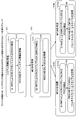
- FIG. 1 is a diagram showing an example of multicast transmission in a single cell according to the first aspect.
- the UE performs CA or DC using a plurality of cells (here, cells # 0 to # 2).
- cells # 0 to # 2 a plurality of cells
- type a a certain type of multicast transmission is supported in cell # 0 which is a PCell.
- cell # 0 contains one or more BWPs. Multicast transmission may be supported in at least one BWP in cell # 0.
- cell # 0 includes initial BWP (BWP # 0), BWP # 1 and # 2, and BWP # 1 supports type a multicast services.
- FIG. 1 is merely an example, and the number and types of BWPs that support multicast transmission within a single cell are not limited to those shown. Further, in FIG. 1, cells # 0 and # 1 are provided in FR1 and cells # 2 are provided in FR2, but these are merely examples and are not limited to those shown. For example, cells # 0 to # 3 may belong to the same FR, or at least two of cells # 0 to # 3 may belong to different FRs.
- the plurality of cells supporting multicast transmission may be a plurality of cells belonging to different cell groups, or may be a plurality of cells belonging to the same cell group or CA.
- Multicast transmission may be supported in one or more BWPs in each of the plurality of cells.
- the one or more BWPs may be determined in the same manner as a single cell that supports the multicast transmission.
- a certain carrier may only support a single type of multicast service.
- a carrier or a BWP with that carrier may support multiple types of multicast services.
- the multicast service type used in each cell (or each BWP) may be notified to the UE by at least one of higher layer signaling and L1 signaling.
- the UE may receive information (multicast type information) indicating the type of the multicast service for each cell (or for each BWP).
- the multicast type information may be notified by RRC signaling (may be an RRC parameter), may be included in system information (eg, SIB20), or may be included in information transmitted by MCCH. May be good.
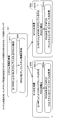
- FIG. 2 is a diagram showing an example of multicast transmission in a plurality of cells according to the first aspect.
- the UE performs CA or DC using a plurality of cells (here, cells # 0 to # 3).
- cells # 0 and # 3 which are PCells.
- cell # 0 supports type a and b multicast services
- cell # 2 supports type c multicast services.
- At least one of the types supported by each cell that supports multicast transmission may be supported by one or more BWPs. Between BWPs in the same cell, the supported types may be the same or at least one type may be different.
- BWP # 1 in cell # 0 of FIG. 2 supports multicast services of types a and b, while BWP # 2 supports multicast services of type a and does not support multicast services of type b.
- BWP # 0 to # 2 in cell # 2 of FIG. 2 support the same type c multicast service.
- FIG. 2 is merely an example, and the number of cells that support multicast transmission, the number and types of BWPs that support multicast transmission in each cell, and the like are not limited to those shown. Further, in FIG. 2, cells # 0 and # 1 are FR1, cells # 2 and # 3 are FR2, and cells supporting multicast transmission are provided for each FR, but these are merely examples and are shown. Not limited. For example, a cell that supports multicast transmission may be provided for each cell group.
- the multicast service can be supported in BWP units.
- BWP-related configurations such as BWP size are aligned between UEs having different capabilities. May be good.
- Multicast transmission may be supported for one or more UEs in at least one UE state, connected, idle, and inactive.
- multicast transmission may be supported by at least one of the following UEs: -Only one or more UEs in the connected state-Only one or more UEs in the idle state-Only one or more UEs in the inactive state-One or more UE states in the connected state, idle state, and inactive state UE
- One or more UEs receiving multicast transmissions may support at least one group of the following, which is determined based on the UE state: (1) A group containing only UEs (s) in a specific UE state (for example, idle state, inactive state or connected state) (2) UEs in the first UE state (for example, idle / inactive state) ( Either the group containing s) or the group containing the UE (s) in the second UE state (eg, connected state) (3) The UE in the first UE state (eg idle / inactive state) Supports both the first group containing (s) and the second group containing UE (s) in the second UE state (eg, connected state)
- the configuration information (multicast setting information) related to the multicast transmission includes the first group (for example, the UE in the idle / inactive state) and the second group (for example, the UE in the connected state). ) May be the same (may be common) or different (may be individual).
- common multicast setting information may be notified to the idle / inactive UE and the connected UE by the multicast system information (for example, SIB20).
- the common multicast setting information may be notified using L1 signaling (for example, at least one of information transmitted via MCCH and DCI) in addition to the multicast system information, or L1 signaling may be used. It may be notified only by the system information for multicast without.
- the multicast setting information for the UE in the idle / inactive state may be notified by the multicast system information (for example, SIB20).
- the multicast setting information may be notified using L1 signaling (for example, at least one of information transmitted via MCCH and DCI) in addition to the multicast system information, or multicast without using L1 signaling. You may be notified only by the system information.
- the multicast setting information for the UE in the connected state may be notified by the multicast system information (for example, SIB20).
- the multicast setting information may be notified using L1 signaling (for example, at least one of information transmitted via MCCH and DCI) in addition to the multicast system information, or multicast without using L1 signaling. You may be notified only by the system information.
- the multicast setting information for the connected UE may be notified by RRC signaling.
- the multicast setting information may be notified using L1 signaling (for example, at least one of information transmitted via MCCH and DCI) in addition to the RRC signaling, or only RRC signaling without using L1 signaling. You may be notified by.
- the UE receives the system information for multicast (for example, step S11 in FIG. 3) and sets the MCCH based on the configuration information (MCCH setting information) related to the MCCH included in the system information. It may be received (eg, step S12 in FIG. 3) and MTCH may be received based on the information transmitted by the MCCH (eg, multicast configuration information) (eg, step S13 in FIG. 3).
- the UE may be at least one of an idle UE, an inactive UE, and a connected UE.
- the UE may receive system information for multicast (eg, step S21 in FIG. 4) and receive MTCH based on the information contained in the system information (eg, multicast configuration information). Good (eg, step S22 in FIG. 4).
- the UE may be at least one of an idle UE, an inactive UE, and a connected UE.
- the UE receives an RRC message (eg, an RRC reconfiguration message) (eg, step S31 in FIG. 5) and uses the information contained in the RRC message (eg, multicast configuration information).
- MTCH may be received based on (for example, step S31 in FIG. 5).
- the UE may be a connected UE.
- the UE receives the MTCH (multicast data) via the PDSCH scheduled by DCI, which is CRC scrambled by a specific radio network temporary identifier (RNTI). You may.
- RNTI radio network temporary identifier
- the specific RNTI may be a RNTI for each multicast service (for each type of multicast service).
- the specific RNTI may be referred to as, for example, group (G or GC) -RNTI, single cell (SC) -RNTI, multicast (M or MC) -RNTI, group cast RNTI, or the like.
- the G-RNTI value may be the same among UEs belonging to the same group (for example, (1) to (3) above).
- One or more G-RNTIs may be introduced in a certain UE.
- Each G-RNTI may be associated with one or more types of multicast transmissions supported by the UE in a cell or cells.
- one or more G-RNTIs use at least one of system information for multicast and L1 signaling (eg, at least one of information transmitted by MCCH and DCI). May be notified.
- one or more G-RNTIs provide at least one of system information for multicast, L1 signaling (for example, at least one of information transmitted by MCCH and DCI) and RRC signaling. It may be notified using.
- the maximum number X of G-RNTIs that can be set in a certain UE in a certain cell or a certain BWP may be defined in the specifications, or may be set (configure) based on the capability of the UE. For example, the maximum number X of the G-RNTI may be set so as not to exceed the UE capability reported by the UE.
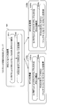
- FIG. 3 is a diagram showing an example of the first scheduling of multicast transmission according to the second aspect.
- the first scheduling shown in FIG. 3 may be applied to a group containing at least UEs in an idle / inactive state.
- the group may or may not include a connected UE.
- the UE may receive system information for multicast (for example, SIB20). Specifically, in step S111, the UE monitors a search space (SS) set that includes one or more search spaces and CRC scrambles the PDCCH (eg, System Information (SI) -RNTI) by a particular RNTI (eg, System Information (SI) -RNTI). DCI) may be detected.
- SS search space
- SI System Information
- SI System Information
- the UE may acquire the system information via the PDSCH scheduled by the DCI.
- the system information may include configuration information (MCCH setting information) related to MCCH.
- the MCCH setting information includes, for example, a cycle in which the MCCH is transmitted (repetition period), a time offset (time offset), and a cycle in which the information transmitted by the MCCH is updated (modification period). At least one may be included.
- step S12 the UE receives the MCCH based on the MCCH setting information in the system information. Specifically, in step S121, the UE may monitor the SS set and detect the PDCCH (DCI), which is CRC scrambled by a particular identifier.
- DCI PDCCH
- the specific identifier may be a specific RNTI (for example, Single Cell (SC) -RNTI) or a temporary mobile group identifier (Temporary Mobile Group Identifier).
- the specific identifier may be included in the MCCH setting information.
- the UE may acquire the MCCH via the PDSCH scheduled by the DCI.
- the MCCH may be repeatedly transmitted in the above-mentioned repeating cycle.
- the same information may be transmitted in the MCCH for each repetition cycle within the update cycle.
- the information transmitted by the MCCH is changed, it may be notified that the information transmitted by the MCCH is changed in the next update cycle in the immediately preceding update cycle.
- the notification may be referred to as an SC-MCCH change notification or the like.
- the PDCCH may be used for the notification.
- the UE may control intermittent reception (Discontinuous Reception (DRX)) based on the notification. Specifically, the UE may be activated only for the time when the notification is performed, and may transition to the DRX state if the information transmitted by the MCCH is not changed.
- DRX discontinuous Reception
- the UE receives the MTCH based on the information transmitted by the MCCH (for example, setting information related to MTCH (multicast) (also referred to as MTCH setting information, multicast setting information, etc.)).
- the information transmitted in the MTCH setting information may include, for example, information indicating at least one of the following.
- ⁇ G-RNTI -DCI payload size-Cells that support multicast transmission-BWP that supports multicast transmission -Multicast transmission type supported by each cell or BWP-Control Resource Set (CORESET) in which the PDCCH that schedules the PDSCH that transmits the MTCH is arranged.
- the UE may monitor the SS set to detect a CRC scrambled PDCCH (DCI) by a particular RNTI (eg, G-RNTI).
- DCI CRC scrambled PDCCH
- G-RNTI eg, G-RNTI
- the specific RNTI may have a different value for each type of multicast transmission. For example, FIG. 3 shows G-RNTI_a corresponding to type a multicast transmission and G-RNTI_b corresponding to type b multicast transmission.
- the UE may acquire the MTCH corresponding to each of the types a and b via the PDSCH scheduled by the DCI.
- steps S13a and 13b, S131a and 131b, S132a and 132b each assume different types of multicast transmission, but the operations may be the same.
- FIG. 4 is a diagram showing an example of a second scheduling of multicast transmission according to the second aspect.
- the second scheduling shown in FIG. 4 may be applied to a group containing at least UEs in an idle / inactive state.
- the group may or may not include a connected UE.
- step S21 in FIG. 4 is the same as that of step S11 in FIG.
- the system information for multicast (for example, SIB20) acquired in step S212 may include the MTCH setting information instead of the MCCH setting information.
- the information included in the MTCH setting information is as described in the first scheduling.
- steps S22a and 22b the UE receives the MTCH based on the MTCH setting information in the system information acquired in step S21.
- the details of steps S22a and S22b are the same as those of steps S13a and S13b in FIG.
- FIG. 5 is a diagram showing an example of a third scheduling of multicast transmission according to the second aspect.
- the third scheduling shown in FIG. 5 may be applied to a group containing UEs in a connected state.
- the group does not include UEs that are idle / inactive.
- the UE may receive the MTCH setting information via RRC signaling. Specifically, in step S311 the UE monitors an SS set containing one or more search spaces and detects a CRC scrambled PDCCH (DCI) by a UE-specific RNTI (eg, Cell (C) -RNTI). You may.
- DCI CRC scrambled PDCCH
- the UE may acquire the MTCH setting information via the PDSCH scheduled by the DCI.
- the MTCH configuration information may be included, for example, in the RRC reconfiguration message.
- the information included in the MTCH setting information is as described in the first scheduling.
- steps S32a and 32b the UE receives the MTCH based on the MTCH setting information in the system information acquired in step S31.
- the details of steps S32a and S32b are the same as those of steps S13a and S13b in FIG.
- MTCH multicast data
- the second aspect it is possible to appropriately schedule the multicast transmission for each UE state (for example, idle state, inactive state, connected state) UE.
- UE state for example, idle state, inactive state, connected state
- the UE behavior related to the reception of at least one PDCCH and PDSCH related to the multicast transmission will be described.
- the UE operation may be the same or different between at least two UEs in the idle state, the inactive state and the connected state.
- the UE operation is, for example, assuming a transmission setting identifier (Transmission Configuration Indicator (TCI)) state (TCI state) for receiving MTCH (or MCCH and MTCH), and uplink control information (UCI). )) May include at least one of the transmission controls.
- TCI Transmission Configuration Indicator
- UCI uplink control information
- the TCI state is, for example, a target channel (in other words, a reference signal (RS) for the channel) and another signal (for example, another reference signal (RS)). It may be information about the pseudo-collocation (Quasi-Co-Location (QCL)) of.
- the TCI state may be referred to as spatial reception parameters, spatial relation information (SRI), and the like.
- the TCI state can also be said to be information indicating a beam used for transmission of the target channel.
- QCL is an index showing the statistical properties of at least one signal and channel (signal / channel). For example, when one signal / channel and another signal / channel have a QCL relationship, a Doppler shift, a Doppler spread, and an average delay are performed between these different signals / channels. ), Delay spread, and spatial parameter (for example, spatial Rx parameter) can be assumed to be the same (QCL for at least one of these). You may.
- the spatial reception parameter may correspond to the received beam of the UE (for example, the received analog beam), or the beam may be specified based on the spatial QCL.
- the QCL (or at least one element of the QCL) in the present disclosure may be read as sQCL (spatial QCL).
- the UE may determine at least one of the transmission beam (Tx beam) and the reception beam (Rx beam) of the signal / channel based on the TCI state of the signal / channel or the QCL relationship.
- At least one channel in which the TCI state or spatial relationship is set is, for example, PDSCH, PDCCH, uplink shared channel (Physical Uplink Shared Channel (PUSCH)), and uplink control channel (Physical Uplink Control Channel (PUCCH)). It may be.
- PDSCH Physical Uplink Shared Channel
- PDCCH Physical Uplink Control Channel
- the RS having a QCL relationship with the channel is, for example, a synchronization signal block (Synchronization Signal Block (SSB)), a channel state information reference signal (Channel State Information Reference Signal (CSI-RS)), and a measurement reference signal (Sounding). It may be at least one such as Reference Signal (SRS)), CSI-RS for tracking (also referred to as Tracking Reference Signal (TRS)), and a reference signal for QCL detection (also referred to as QRS).
- SRS Reference Signal
- TRS Tracking Reference Signal
- QRS reference signal for QCL detection
- the SSB is a signal block including at least one of a primary synchronization signal (Primary Synchronization Signal (PSS)), a secondary synchronization signal (Secondary Synchronization Signal (SSS)), and a broadcast channel (Physical Broadcast Channel (PBCH)).
- PSS Primary Synchronization Signal
- SSS Secondary Synchronization Signal
- PBCH Physical Broadcast Channel
- the SSB may be referred to as an SS / PBCH block.
- the UE that receives the multicast transmission is the MTCH and the MCCH based on the PDSCH (or the antenna port of the PDSCH demodulation reference signal (Demodulation Reference Signal (DMRS))) and the information (TCI state) regarding the QCL with the predetermined RS.
- DMRS Demodulation Reference Signal
- which beam (also referred to as TCI state or QCL relationship) used by a UE in an idle / inactive state to receive the PDSCH may be an implementation of the UE, or may be determined by the detected SSB. It may be determined based on it, or it may be the same as the system information for multicast (for example, SIB20).
- SIB20 system information for multicast
- which beam (also referred to as TCI state or QCL relationship) used by the connected state UE to receive the PDSCH may be determined using at least one of RRC signaling, MAC signaling and DCI.
- the TCI state (QCL relationship) of the connected state UE may be determined based on the information transmitted by the system information for multicast.
- the UE may notify (set) M (M ⁇ 1) TCI states (QCL information for M PDSCHs) for PDSCH by RRC signaling.
- the number M of TCI states set in the UE may be limited by at least one of the UE capability and the QCL type.
- the DCI used for scheduling the PDSCH may include a field indicating the TCI state for the PDSCH (for example, it may be called a TCI field, a TCI state field, or the like).
- the predetermined number of TCI states are activated (for example, 8 TCI states are activated by using MAC CE). Or it may be specified).
- the value of the TCI field in the DCI may indicate one of the TCI states activated by MAC CE.
- FIG. 6 is a diagram showing an example of beam control related to multicast transmission according to the third aspect.
- the base station for example, gNB
- the base station may perform multicast transmission using beam cycling of a plurality of beams (here, beams # 1 to # 4). Note that beam cycling is also called beam sweeping or the like, and the beam transmitted from the base station may be switched in time.
- each beam that performs multicast transmission may be associated with a predetermined RS or a resource for the predetermined RS (for example, SSB or CSI-RS resource).
- the beams # 1 to # 4 may be associated with SSB # 1 to # 4, or CSI-RS resources # 1 to # 4, respectively.
- the DMRS of the PDSCH determines the beams # 1 and # 2.
- the reception of the PDSCH may be controlled on the assumption (assumed) that it has a QCL relationship with the SSB # 1 and # 2 transmitted in 2.
- the UE in the connected state has SSB # 1 to # 4 (or CSI-RS resources # 1 to # 4) and QCL in which the DMRS of the PDSCH is transmitted by the beams # 1 to # 4.
- TCI states each indicating a relationship, may be received by RRC signaling.
- the UE is determined by the DMRS of the PDSCH based on the TCI state indicated by the value of a certain field (for example, the TCI field) in the DCI (DCI CRC scrambled by the G-RNTI) used for scheduling the PDSCH.
- the reception of the PDSCH may be controlled on the assumption that it has a QCL relationship with the SSB # 3 (or CSI-RS resource # 3) transmitted by the beam # 3.
- the UCI provides delivery confirmation information (eg, Hybrid Automatic Repeat reQuest ACKnowledgement (HARQ-ACK), ACK / NACK, etc.), Channel State Information (CSI) and Scheduling for PDSCH. At least one of Request (SR)) may be included.
- delivery confirmation information eg, Hybrid Automatic Repeat reQuest ACKnowledgement (HARQ-ACK), ACK / NACK, etc.
- CSI Channel State Information
- SR Request
- HARQ-ACK for multicast transmission may or may not be supported.
- the NR may or may not support CSI feedback for multicast transmission (MTCH or CSI feedback for PDSCH transmitting (MTCH and MCCH)).
- the CSI feedback (transmission) may be referred to as a CSI report or the like.
- RS for example, Sounding Reference Signal (SRS)
- TDD Time Division Duplex
- the idle / inactive UE does not have to perform at least one of the HARQ-ACK, the CSI report, and the RS (for example, SRS) for estimating the channel condition.
- the connected / inactive UE may perform at least one of the HARQ-ACK, the CSI report, and the RS (for example, SRS) for channel condition estimation.
- At least one of the following restrictions may or may not be provided for the PDSCH associated with the MTCH.
- TB Number of transport blocks
- TB Number of layers (also called rank)
- DMRS ports Number of DMRS antenna ports
- SCS Subcarrier Spacing
- CP Cyclic Prefix
- TBS At least one of Modulation order and Transport block Size
- the PDSCH associated with the MTCH may only support a specific SCS (eg, 120 kHz).
- a specific SCS e.g, 120 kHz
- the PDSCH may support not only the specific SCS but also other SCSs (for example, 15 kHz, 30 kHz, 60 kHz, 240 KHz, 480 kHz, 960 kHz, etc.).
- a normal CP is applied to the PDSCH associated with the MTCH, but an extended CP longer than the normal CP It does not have to be applied.
- a specific SCS for example, 60 kHz may be applied to the PDSCH.
- a specific SCS for example, 15 kHz, 30 kHz, 120 kHz, 240 kHz, 480 kHz, 960 kHz
- the PDSCH associated with the MTCH not only the normal CP but also the extended CP may be applied. ..
- the modulation order of the PDSCH associated with the MTCH may not be expected to be greater than 2 or 4.
- the modulation order "2" is Quadrature Phase Shift Keying (QPSK)
- the modulation order "4" is 16 Quadrature Amplitude Modulation (QAM). That is, 64QAM having a modulation order of "6” or 256QAM having a modulation order of "8" may not be applied to the PDSCH.
- At least one of the TBS and Modulation and Coding Scheme (MCS) indexes applied to the PDSCH associated with the MTCH is system information for multicast (eg SIB20), RRC signaling (eg, eg). It may be specified based on at least one of RRC reconfiguration message or RRC resume message), physical layer signaling (eg, information transmitted on PDSCH associated with MCCH or DCI).
- the TBS may be determined by the UE based on the MCS index or the like.
- the transmission or reception of the PDSCH associated with the MTCH can be appropriately controlled.
- Multicast transmission may be combined with at least one of the following: (5.1) Multiple transmission and reception points (TRP) (multi-TRP) (5.2) Code Block Group (CBG) -based transmission (5.3) Semi-Persistent Scheduling (SPS)) (5.4) Duplication in the Packet Data Convergence Protocol (PDCP) layer
- TRP Multiple transmission and reception points
- CBG Code Block Group
- SPS Semi-Persistent Scheduling
- PDCP Packet Data Convergence Protocol
- a plurality of TRPs with PDSCH associated with the MTCH may be transmitted.
- CBG includes one or more code blocks (Code Block (CB)). Each CB is configured by segmenting 1TB.
- CBG-based transmission of PDSCH associated with MTCH may be supported or configured.
- the CBG-based transmission may be configured based on whether HARQ-ACK feedback is supported or configured for the multicast transmission.
- CBG-based transmission of PDSCH associated with MTCH may be configured.
- the CBG-based transmission of the PDSCH associated with the MTCH may not be configured.
- SPS may be applied to the PDSCH associated with the MTCH.
- a DCI Group DCI
- the DCI may be CRC scrambled by the G-RNTI.
- Data related to multicast transmission may be duplicated in the PDCP layer and transmitted in a plurality of cells.
- the UE may select the data transmitted in any of the plurality of cells, or may combine the data transmitted in at least two of the plurality of cells.
- FIGS. 7A and 7B are diagrams showing an example of PDCP replication according to other aspects.
- two multicast data associated with a radio bearer eg, a multicast bearer
- the two multicast data may be mapped to two MTCHs corresponding to different cells # 1 and # 2, respectively, in the RLC layer.
- the two MTCHs are mapped to two DL-SCHs corresponding to different cells # 1 and # 2, respectively, in the MAC layer.
- the two DL-SCHs may be mapped to two PDSCHs corresponding to different cells # 1 and # 2, respectively, in the L1 layer.
- both the PDSCH corresponding to cell # 1 and the PDSCH corresponding to cell # 2 may be multicast.
- the PDSCH corresponding to cell # 1 may be multicast, while the PDSCH corresponding to cell # 2 may be unicast.
- wireless communication system Wireless communication system
- communication is performed using any one of the wireless communication methods according to each of the above-described embodiments of the present disclosure or a combination thereof.
- FIG. 8 is a diagram showing an example of a schematic configuration of a wireless communication system according to an embodiment.
- the wireless communication system 1 may be a system that realizes communication using Long Term Evolution (LTE), 5th generation mobile communication system New Radio (5G NR), etc. specified by Third Generation Partnership Project (3GPP). ..
- the wireless communication system 1 may support dual connectivity between a plurality of Radio Access Technologies (RATs) (Multi-RAT Dual Connectivity (MR-DC)).
- MR-DC is dual connectivity between LTE (Evolved Universal Terrestrial Radio Access (E-UTRA)) and NR (E-UTRA-NR Dual Connectivity (EN-DC)), and dual connectivity between NR and LTE (NR-E).
- -UTRA Dual Connectivity (NE-DC) may be included.
- the LTE (E-UTRA) base station (eNB) is the master node (Master Node (MN)), and the NR base station (gNB) is the secondary node (Secondary Node (SN)).
- the NR base station (gNB) is MN
- the LTE (E-UTRA) base station (eNB) is SN.
- the wireless communication system 1 has dual connectivity between a plurality of base stations in the same RAT (for example, dual connectivity (NR-NR Dual Connectivity (NN-DC)) in which both MN and SN are NR base stations (gNB). )) May be supported.
- a plurality of base stations in the same RAT for example, dual connectivity (NR-NR Dual Connectivity (NN-DC)) in which both MN and SN are NR base stations (gNB). )
- NR-NR Dual Connectivity NR-DC
- gNB NR base stations
- the wireless communication system 1 includes a base station 11 that forms a macro cell C1 having a relatively wide coverage, and a base station 12 (12a-12c) that is arranged in the macro cell C1 and forms a small cell C2 that is narrower than the macro cell C1. You may prepare.
- the user terminal 20 may be located in at least one cell. The arrangement, number, and the like of each cell and the user terminal 20 are not limited to the mode shown in the figure.
- the base stations 11 and 12 are not distinguished, they are collectively referred to as the base station 10.
- the user terminal 20 may be connected to at least one of the plurality of base stations 10.
- the user terminal 20 may use at least one of carrier aggregation (Carrier Aggregation (CA)) and dual connectivity (DC) using a plurality of component carriers (Component Carrier (CC)).
- CA Carrier Aggregation
- DC dual connectivity
- CC Component Carrier
- Each CC may be included in at least one of a first frequency band (Frequency Range 1 (FR1)) and a second frequency band (Frequency Range 2 (FR2)).
- the macro cell C1 may be included in FR1 and the small cell C2 may be included in FR2.
- FR1 may be in a frequency band of 6 GHz or less (sub 6 GHz (sub-6 GHz)), and FR2 may be in a frequency band higher than 24 GHz (above-24 GHz).
- the frequency bands and definitions of FR1 and FR2 are not limited to these, and for example, FR1 may correspond to a frequency band higher than FR2.
- the user terminal 20 may perform communication using at least one of Time Division Duplex (TDD) and Frequency Division Duplex (FDD) in each CC.
- TDD Time Division Duplex
- FDD Frequency Division Duplex
- the plurality of base stations 10 may be connected by wire (for example, optical fiber compliant with Common Public Radio Interface (CPRI), X2 interface, etc.) or wirelessly (for example, NR communication).
- wire for example, optical fiber compliant with Common Public Radio Interface (CPRI), X2 interface, etc.
- NR communication for example, when NR communication is used as a backhaul between base stations 11 and 12, the base station 11 corresponding to the upper station is an Integrated Access Backhaul (IAB) donor, and the base station 12 corresponding to a relay station (relay) is IAB. It may be called a node.
- IAB Integrated Access Backhaul
- relay station relay station
- the base station 10 may be connected to the core network 30 via another base station 10 or directly.
- the core network 30 may include at least one such as Evolved Packet Core (EPC), 5G Core Network (5GCN), and Next Generation Core (NGC).
- EPC Evolved Packet Core
- 5GCN 5G Core Network
- NGC Next Generation Core
- the user terminal 20 may be a terminal that supports at least one of communication methods such as LTE, LTE-A, and 5G.
- a wireless access method based on Orthogonal Frequency Division Multiplexing may be used.
- OFDM Orthogonal Frequency Division Multiplexing
- DL Downlink
- UL Uplink
- CP-OFDM Cyclic Prefix OFDM
- DFT-s-OFDM Discrete Fourier Transform Spread OFDM
- OFDMA Orthogonal Frequency Division Multiple. Access
- SC-FDMA Single Carrier Frequency Division Multiple Access
- the wireless access method may be called a waveform.
- another wireless access system for example, another single carrier transmission system, another multi-carrier transmission system
- the UL and DL wireless access systems may be used as the UL and DL wireless access systems.
- downlink shared channels Physical Downlink Shared Channel (PDSCH)
- broadcast channels Physical Broadcast Channel (PBCH)
- downlink control channels Physical Downlink Control
- Channel PDCCH
- the uplink shared channel Physical Uplink Shared Channel (PUSCH)
- the uplink control channel Physical Uplink Control Channel (PUCCH)
- the random access channel shared by each user terminal 20 are used.
- Physical Random Access Channel (PRACH) Physical Random Access Channel or the like may be used.
- User data, upper layer control information, System Information Block (SIB), etc. are transmitted by PDSCH.
- User data, upper layer control information, and the like may be transmitted by the PUSCH.
- the Master Information Block (MIB) may be transmitted by the PBCH.
- Lower layer control information may be transmitted by PDCCH.
- the lower layer control information may include, for example, downlink control information (Downlink Control Information (DCI)) including scheduling information of at least one of PDSCH and PUSCH.
- DCI Downlink Control Information
- the DCI that schedules PDSCH may be called DL assignment, DL DCI, etc.
- the DCI that schedules PUSCH may be called UL grant, UL DCI, etc.
- the PDSCH may be read as DL data
- the PUSCH may be read as UL data.
- a control resource set (COntrol REsource SET (CORESET)) and a search space (search space) may be used to detect the PDCCH.
- CORESET corresponds to a resource that searches for DCI.
- the search space corresponds to the search area and search method of PDCCH candidates (PDCCH candidates).
- One CORESET may be associated with one or more search spaces. The UE may monitor the CORESET associated with a search space based on the search space settings.
- One search space may correspond to PDCCH candidates corresponding to one or more aggregation levels.
- One or more search spaces may be referred to as a search space set.
- the "search space”, “search space set”, “search space setting”, “search space set setting”, “CORESET”, “CORESET setting”, etc. of the present disclosure may be read as each other.
- channel state information (Channel State Information (CSI)
- delivery confirmation information for example, it may be called Hybrid Automatic Repeat reQuest ACK knowledgement (HARQ-ACK), ACK / NACK, etc.
- scheduling request (Scheduling Request ( Uplink Control Information (UCI) including at least one of SR)
- the PRACH may transmit a random access preamble for establishing a connection with the cell.
- downlinks, uplinks, etc. may be expressed without “links”. Further, it may be expressed without adding "Physical" at the beginning of various channels.
- a synchronization signal (Synchronization Signal (SS)), a downlink reference signal (Downlink Reference Signal (DL-RS)), and the like may be transmitted.
- the DL-RS includes a cell-specific reference signal (Cell-specific Reference Signal (CRS)), a channel state information reference signal (Channel State Information Reference Signal (CSI-RS)), and a demodulation reference signal (DeModulation).
- CRS Cell-specific Reference Signal
- CSI-RS Channel State Information Reference Signal
- DeModulation Demodulation reference signal
- Reference Signal (DMRS)), positioning reference signal (Positioning Reference Signal (PRS)), phase tracking reference signal (Phase Tracking Reference Signal (PTRS)), and the like may be transmitted.
- PRS Positioning Reference Signal
- PTRS Phase Tracking Reference Signal
- the synchronization signal may be, for example, at least one of a primary synchronization signal (Primary Synchronization Signal (PSS)) and a secondary synchronization signal (Secondary Synchronization Signal (SSS)).
- PSS Primary Synchronization Signal
- SSS Secondary Synchronization Signal
- the signal block including SS (PSS, SSS) and PBCH (and DMRS for PBCH) may be referred to as SS / PBCH block, SS Block (SSB) and the like.
- SS, SSB and the like may also be called a reference signal.
- a measurement reference signal Sounding Reference Signal (SRS)
- a demodulation reference signal DMRS
- UL-RS Uplink Reference Signal
- UE-specific Reference Signal UE-specific Reference Signal
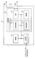
- FIG. 9 is a diagram showing an example of the configuration of the base station according to the embodiment.
- the base station 10 includes a control unit 110, a transmission / reception unit 120, a transmission / reception antenna 130, and a transmission line interface 140.
- the control unit 110, the transmission / reception unit 120, the transmission / reception antenna 130, and the transmission line interface 140 may each be provided with one or more.
- the functional blocks of the feature portion in the present embodiment are mainly shown, and it may be assumed that the base station 10 also has other functional blocks necessary for wireless communication. A part of the processing of each part described below may be omitted.
- the control unit 110 controls the entire base station 10.
- the control unit 110 can be composed of a controller, a control circuit, and the like described based on the common recognition in the technical field according to the present disclosure.
- the control unit 110 may control signal generation, scheduling (for example, resource allocation, mapping) and the like.
- the control unit 110 may control transmission / reception, measurement, and the like using the transmission / reception unit 120, the transmission / reception antenna 130, and the transmission line interface 140.
- the control unit 110 may generate data to be transmitted as a signal, control information, a sequence, and the like, and transfer the data to the transmission / reception unit 120.
- the control unit 110 may perform call processing (setting, release, etc.) of the communication channel, state management of the base station 10, management of radio resources, and the like.
- the transmission / reception unit 120 may include a baseband unit 121, a Radio Frequency (RF) unit 122, and a measurement unit 123.
- the baseband unit 121 may include a transmission processing unit 1211 and a reception processing unit 1212.
- the transmission / reception unit 120 includes a transmitter / receiver, an RF circuit, a baseband circuit, a filter, a phase shifter, a measurement circuit, a transmission / reception circuit, and the like, which are described based on common recognition in the technical fields according to the present disclosure. be able to.
- the transmission / reception unit 120 may be configured as an integrated transmission / reception unit, or may be composed of a transmission unit and a reception unit.
- the transmission unit may be composed of a transmission processing unit 1211 and an RF unit 122.
- the receiving unit may be composed of a receiving processing unit 1212, an RF unit 122, and a measuring unit 123.
- the transmitting / receiving antenna 130 can be composed of an antenna described based on common recognition in the technical field according to the present disclosure, for example, an array antenna.
- the transmission / reception unit 120 may transmit the above-mentioned downlink channel, synchronization signal, downlink reference signal, and the like.
- the transmission / reception unit 120 may receive the above-mentioned uplink channel, uplink reference signal, and the like.
- the transmission / reception unit 120 may form at least one of a transmission beam and a reception beam by using digital beamforming (for example, precoding), analog beamforming (for example, phase rotation), and the like.
- digital beamforming for example, precoding
- analog beamforming for example, phase rotation
- the transmission / reception unit 120 processes, for example, Packet Data Convergence Protocol (PDCP) layer processing and Radio Link Control (RLC) layer processing (for example, RLC) for data, control information, etc. acquired from control unit 110.
- PDCP Packet Data Convergence Protocol
- RLC Radio Link Control
- MAC Medium Access Control
- HARQ retransmission control HARQ retransmission control
- the transmission / reception unit 120 performs channel coding (may include error correction coding), modulation, mapping, filtering, and discrete Fourier transform (Discrete Fourier Transform (DFT)) for the bit string to be transmitted.
- the base band signal may be output by performing processing (if necessary), inverse fast Fourier transform (IFFT) processing, precoding, digital-analog transform, and other transmission processing.
- IFFT inverse fast Fourier transform
- the transmission / reception unit 120 may perform modulation, filtering, amplification, etc. on the baseband signal to the radio frequency band, and transmit the signal in the radio frequency band via the transmission / reception antenna 130. ..
- the transmission / reception unit 120 may perform amplification, filtering, demodulation to a baseband signal, or the like on the signal in the radio frequency band received by the transmission / reception antenna 130.
- the transmission / reception unit 120 (reception processing unit 1212) performs analog-digital conversion, fast Fourier transform (FFT) processing, and inverse discrete Fourier transform (IDFT) on the acquired baseband signal. )) Processing (if necessary), filtering, demapping, demodulation, decoding (may include error correction decoding), MAC layer processing, RLC layer processing, PDCP layer processing, and other reception processing are applied. User data and the like may be acquired.
- FFT fast Fourier transform
- IDFT inverse discrete Fourier transform
- the transmission / reception unit 120 may perform measurement on the received signal.
- the measuring unit 123 may perform Radio Resource Management (RRM) measurement, Channel State Information (CSI) measurement, or the like based on the received signal.
- the measuring unit 123 has received power (for example, Reference Signal Received Power (RSRP)) and reception quality (for example, Reference Signal Received Quality (RSRQ), Signal to Interference plus Noise Ratio (SINR), Signal to Noise Ratio (SNR)).
- RSRP Reference Signal Received Power
- RSSQ Reference Signal Received Quality
- SINR Signal to Noise Ratio
- Signal strength for example, Received Signal Strength Indicator (RSSI)
- propagation path information for example, CSI
- the measurement result may be output to the control unit 110.
- the transmission line interface 140 transmits and receives signals (backhaul signaling) to and from devices included in the core network 30, other base stations 10, and the like, and user data (user plane data) and control plane for the user terminal 20. Data or the like may be acquired or transmitted.
- the transmitting unit and the receiving unit of the base station 10 in the present disclosure may be composed of at least one of the transmission / reception unit 120, the transmission / reception antenna 130, and the transmission line interface 140.
- the transmission / reception unit 120 may transmit downlink control information. Further, the transmission / reception unit 120 may transmit a downlink shared channel.
- the downlink control information may have a cyclic redundancy check (CRC) bit scrambled using a wireless network temporary identifier (RNTI) common to one or more terminals.
- CRC cyclic redundancy check
- RNTI wireless network temporary identifier
- the transmission / reception unit 120 may transmit the RNTI for each type of multicast service.
- the transmission / reception unit 120 receives the data using the physical downlink shared channel associated with the multicast control channel (MCCH) when the user terminal 20 is at least one of the idle state, the inactive state, and the connected state.
- MCCH multicast control channel
- the above MTCH setting information, multicast setting information may be transmitted.
- the transmission / reception unit 120 uses the system information for multicast to receive information (for example, the MTCH setting).
- Information, multicast setting information may be transmitted.
- the transmission / reception unit 120 uses radio resource control (RRC) signaling to transmit information for receiving the data (for example, the MTCH setting information and the multicast setting information). You may.
- RRC radio resource control
- FIG. 10 is a diagram showing an example of the configuration of the user terminal according to the embodiment.
- the user terminal 20 includes a control unit 210, a transmission / reception unit 220, and a transmission / reception antenna 230.
- the control unit 210, the transmission / reception unit 220, and the transmission / reception antenna 230 may each be provided with one or more.
- this example mainly shows the functional blocks of the feature portion in the present embodiment, and it may be assumed that the user terminal 20 also has other functional blocks necessary for wireless communication. A part of the processing of each part described below may be omitted.
- the control unit 210 controls the entire user terminal 20.
- the control unit 210 can be composed of a controller, a control circuit, and the like described based on the common recognition in the technical field according to the present disclosure.
- the control unit 210 may control signal generation, mapping, and the like.
- the control unit 210 may control transmission / reception, measurement, and the like using the transmission / reception unit 220 and the transmission / reception antenna 230.
- the control unit 210 may generate data to be transmitted as a signal, control information, a sequence, and the like, and transfer the data to the transmission / reception unit 220.
- the transmission / reception unit 220 may include a baseband unit 221 and an RF unit 222, and a measurement unit 223.
- the baseband unit 221 may include a transmission processing unit 2211 and a reception processing unit 2212.
- the transmission / reception unit 220 can be composed of a transmitter / receiver, an RF circuit, a baseband circuit, a filter, a phase shifter, a measurement circuit, a transmission / reception circuit, and the like, which are described based on the common recognition in the technical field according to the present disclosure.
- the transmission / reception unit 220 may be configured as an integrated transmission / reception unit, or may be composed of a transmission unit and a reception unit.
- the transmission unit may be composed of a transmission processing unit 2211 and an RF unit 222.
- the receiving unit may be composed of a receiving processing unit 2212, an RF unit 222, and a measuring unit 223.
- the transmitting / receiving antenna 230 can be composed of an antenna described based on common recognition in the technical field according to the present disclosure, for example, an array antenna.
- the transmission / reception unit 220 may receive the above-mentioned downlink channel, synchronization signal, downlink reference signal, and the like.
- the transmission / reception unit 220 may transmit the above-mentioned uplink channel, uplink reference signal, and the like.
- the transmission / reception unit 220 may form at least one of a transmission beam and a reception beam by using digital beamforming (for example, precoding), analog beamforming (for example, phase rotation), and the like.
- digital beamforming for example, precoding
- analog beamforming for example, phase rotation
- the transmission / reception unit 220 processes, for example, PDCP layer processing, RLC layer processing (for example, RLC retransmission control), and MAC layer processing (for example, for data, control information, etc. acquired from the control unit 210). , HARQ retransmission control), etc., to generate a bit string to be transmitted.
- the transmission / reception unit 220 (transmission processing unit 2211) performs channel coding (may include error correction coding), modulation, mapping, filtering processing, DFT processing (if necessary), and IFFT processing for the bit string to be transmitted. , Precoding, digital-to-analog conversion, and other transmission processing may be performed to output the baseband signal.
- Whether or not to apply the DFT process may be based on the transform precoding setting.
- the transmission / reception unit 220 transmission processing unit 2211 described above for transmitting a channel (for example, PUSCH) using the DFT-s-OFDM waveform when the transform precoding is enabled.
- the DFT process may be performed as the transmission process, and if not, the DFT process may not be performed as the transmission process.
- the transmission / reception unit 220 may perform modulation, filtering, amplification, etc. to the radio frequency band on the baseband signal, and transmit the signal in the radio frequency band via the transmission / reception antenna 230. ..
- the transmission / reception unit 220 may perform amplification, filtering, demodulation to a baseband signal, or the like on the signal in the radio frequency band received by the transmission / reception antenna 230.
- the transmission / reception unit 220 (reception processing unit 2212) performs analog-to-digital conversion, FFT processing, IDFT processing (if necessary), filtering processing, demapping, demodulation, and decoding (error correction) for the acquired baseband signal. Decoding may be included), MAC layer processing, RLC layer processing, PDCP layer processing, and other reception processing may be applied to acquire user data and the like.
- the transmission / reception unit 220 may perform measurement on the received signal.
- the measuring unit 223 may perform RRM measurement, CSI measurement, or the like based on the received signal.
- the measuring unit 223 may measure received power (for example, RSRP), reception quality (for example, RSRQ, SINR, SNR), signal strength (for example, RSSI), propagation path information (for example, CSI), and the like.
- the measurement result may be output to the control unit 210.
- the transmission unit and the reception unit of the user terminal 20 in the present disclosure may be composed of at least one of the transmission / reception unit 220, the transmission / reception antenna 230, and the transmission line interface 240.
- RBG size information may be received.
- the transmission / reception unit 220 may receive downlink control information. Further, the transmission / reception unit 220 may receive the downlink shared channel.
- the downlink control information may have a cyclic redundancy check (CRC) bit scrambled using a wireless network temporary identifier (RNTI) common to one or more terminals.
- CRC cyclic redundancy check
- RNTI wireless network temporary identifier
- the transmission / reception unit 220 may receive the RNTI for each type of multicast service.
- the transmission / reception unit 220 receives the data using the physical downlink shared channel associated with the multicast control channel (MCCH).
- MCCH multicast control channel
- the transmission / reception unit 220 uses the system information for multicast to receive the data (for example, the MTCH setting). Information, multicast setting information) may be received.
- the transmission / reception unit 220 uses radio resource control (RRC) signaling to receive information for receiving the data (for example, the MTCH setting information and the multicast setting information). You may.
- RRC radio resource control
- the control unit 210 may control the reception of data associated with the multicast traffic channel (MTCH) using the physical downlink shared channel scheduled by the downlink control information within one or more bandwidth portions in the cell. ..
- MTCH multicast traffic channel
- the control unit 210 may control the reception of the downlink control information.
- each functional block may be realized by using one device that is physically or logically connected, or directly or indirectly (for example, by using two or more physically or logically separated devices). , Wired, wireless, etc.) and may be realized using these plurality of devices.
- the functional block may be realized by combining the software with the one device or the plurality of devices.
- the functions include judgment, decision, judgment, calculation, calculation, processing, derivation, investigation, search, confirmation, reception, transmission, output, access, solution, selection, selection, establishment, comparison, assumption, expectation, and deemed. , Broadcasting, notifying, communicating, forwarding, configuring, reconfiguring, allocating, mapping, assigning, etc.
- a functional block (constituent unit) for functioning transmission may be referred to as a transmitting unit (transmitting unit), a transmitter (transmitter), or the like.
- the method of realizing each of them is not particularly limited.
- the base station, user terminal, and the like in one embodiment of the present disclosure may function as a computer that processes the wireless communication method of the present disclosure.
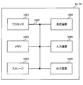
- FIG. 11 is a diagram showing an example of the hardware configuration of the base station and the user terminal according to the embodiment.
- the base station 10 and the user terminal 20 described above may be physically configured as a computer device including a processor 1001, a memory 1002, a storage 1003, a communication device 1004, an input device 1005, an output device 1006, a bus 1007, and the like. ..
- the hardware configuration of the base station 10 and the user terminal 20 may be configured to include one or more of the devices shown in the figure, or may be configured not to include some of the devices.
- processor 1001 may be a plurality of processors. Further, the processing may be executed by one processor, or the processing may be executed simultaneously, sequentially, or by using other methods by two or more processors.
- the processor 1001 may be mounted by one or more chips.
- the processor 1001 For each function of the base station 10 and the user terminal 20, for example, by loading predetermined software (program) on hardware such as the processor 1001 and the memory 1002, the processor 1001 performs an operation and communicates via the communication device 1004. It is realized by controlling at least one of reading and writing of data in the memory 1002 and the storage 1003.
- predetermined software program
- the processor 1001 operates, for example, an operating system to control the entire computer.
- the processor 1001 may be configured by a central processing unit (CPU) including an interface with peripheral devices, a control device, an arithmetic unit, registers, and the like.
- CPU central processing unit
- control unit 110 210
- transmission / reception unit 120 220
- the like may be realized by the processor 1001.
- the processor 1001 reads a program (program code), a software module, data, etc. from at least one of the storage 1003 and the communication device 1004 into the memory 1002, and executes various processes according to these.
- a program program code
- the control unit 110 may be realized by a control program stored in the memory 1002 and operating in the processor 1001, and may be realized in the same manner for other functional blocks.
- the memory 1002 is a computer-readable recording medium, for example, at least a Read Only Memory (ROM), an Erasable Programmable ROM (EPROM), an Electrically EPROM (EEPROM), a Random Access Memory (RAM), or any other suitable storage medium. It may be composed of one.
- the memory 1002 may be referred to as a register, a cache, a main memory (main storage device), or the like.
- the memory 1002 can store a program (program code), a software module, or the like that can be executed to implement the wireless communication method according to the embodiment of the present disclosure.
- the storage 1003 is a computer-readable recording medium, for example, a flexible disk, a floppy (registered trademark) disk, a magneto-optical disk (for example, a compact disc (Compact Disc ROM (CD-ROM)), a digital versatile disk, etc.). At least one of Blu-ray® disks, removable disks, hard disk drives, smart cards, flash memory devices (eg cards, sticks, key drives), magnetic stripes, databases, servers, and other suitable storage media. It may be composed of.
- the storage 1003 may be referred to as an auxiliary storage device.
- the communication device 1004 is hardware (transmission / reception device) for communicating between computers via at least one of a wired network and a wireless network, and is also referred to as, for example, a network device, a network controller, a network card, a communication module, or the like.
- the communication device 1004 includes, for example, a high frequency switch, a duplexer, a filter, a frequency synthesizer, etc. in order to realize at least one of frequency division duplex (Frequency Division Duplex (FDD)) and time division duplex (Time Division Duplex (TDD)). It may be configured to include.
- the transmission / reception unit 120 (220), the transmission / reception antenna 130 (230), and the like described above may be realized by the communication device 1004.
- the transmission / reception unit 120 (220) may be physically or logically separated from the transmission unit 120a (220a) and the reception unit 120b (220b).
- the input device 1005 is an input device (for example, a keyboard, a mouse, a microphone, a switch, a button, a sensor, etc.) that receives an input from the outside.
- the output device 1006 is an output device (for example, a display, a speaker, a Light Emitting Diode (LED) lamp, etc.) that outputs to the outside.
- the input device 1005 and the output device 1006 may have an integrated configuration (for example, a touch panel).
- each device such as the processor 1001 and the memory 1002 is connected by the bus 1007 for communicating information.
- the bus 1007 may be configured by using a single bus, or may be configured by using a different bus for each device.
- the base station 10 and the user terminal 20 include a microprocessor, a digital signal processor (Digital Signal Processor (DSP)), an Application Specific Integrated Circuit (ASIC), a Programmable Logic Device (PLD), a Field Programmable Gate Array (FPGA), and the like. It may be configured to include hardware, and a part or all of each functional block may be realized by using the hardware. For example, processor 1001 may be implemented using at least one of these hardware.
- DSP Digital Signal Processor
- ASIC Application Specific Integrated Circuit
- PLD Programmable Logic Device
- FPGA Field Programmable Gate Array
- the wireless frame may be composed of one or more periods (frames) in the time domain.
- Each of the one or more periods (frames) constituting the wireless frame may be referred to as a subframe.
- the subframe may be composed of one or more slots in the time domain.
- the subframe may have a fixed time length (eg, 1 ms) that is independent of numerology.
- the numerology may be a communication parameter applied to at least one of transmission and reception of a signal or channel.
- Numerology includes, for example, subcarrier spacing (SubCarrier Spacing (SCS)), bandwidth, symbol length, cyclic prefix length, transmission time interval (Transmission Time Interval (TTI)), number of symbols per TTI, and wireless frame configuration.
- SCS subcarrier Spacing
- TTI Transmission Time Interval
- a specific filtering process performed by the transmitter / receiver in the frequency domain, a specific windowing process performed by the transmitter / receiver in the time domain, and the like may be indicated.
- the slot may be composed of one or more symbols in the time domain (Orthogonal Frequency Division Multiple Access (OFDMA) symbol, Single Carrier Frequency Division Multiple Access (SC-FDMA) symbol, etc.). Further, the slot may be a time unit based on numerology.
- OFDMA Orthogonal Frequency Division Multiple Access
- SC-FDMA Single Carrier Frequency Division Multiple Access
- the slot may include a plurality of mini slots. Each minislot may consist of one or more symbols in the time domain. Further, the mini slot may be called a sub slot. A minislot may consist of a smaller number of symbols than the slot.
- a PDSCH (or PUSCH) transmitted in time units larger than the minislot may be referred to as a PDSCH (PUSCH) mapping type A.
- the PDSCH (or PUSCH) transmitted using the minislot may be referred to as PDSCH (PUSCH) mapping type B.
- the wireless frame, subframe, slot, mini slot and symbol all represent the time unit when transmitting a signal.
- the radio frame, subframe, slot, minislot and symbol may have different names corresponding to each.
- the time units such as frames, subframes, slots, mini slots, and symbols in the present disclosure may be read as each other.
- one subframe may be called TTI
- a plurality of consecutive subframes may be called TTI
- one slot or one minislot may be called TTI. That is, at least one of the subframe and TTI may be a subframe (1 ms) in existing LTE, a period shorter than 1 ms (eg, 1-13 symbols), or a period longer than 1 ms. It may be.
- the unit representing TTI may be called a slot, a mini slot, or the like instead of a subframe.
- TTI refers to, for example, the minimum time unit of scheduling in wireless communication.
- the base station schedules each user terminal to allocate radio resources (frequency bandwidth that can be used in each user terminal, transmission power, etc.) in TTI units.
- the definition of TTI is not limited to this.
- the TTI may be a transmission time unit such as a channel-encoded data packet (transport block), a code block, or a code word, or may be a processing unit such as scheduling or link adaptation.
- the time interval for example, the number of symbols
- the transport block, code block, code word, etc. may be shorter than the TTI.
- one or more TTIs may be the minimum time unit for scheduling. Further, the number of slots (number of mini-slots) constituting the minimum time unit of the scheduling may be controlled.
- a TTI having a time length of 1 ms may be referred to as a normal TTI (TTI in 3GPP Rel. 8-12), a normal TTI, a long TTI, a normal subframe, a normal subframe, a long subframe, a slot, or the like.
- TTIs shorter than normal TTIs may be referred to as shortened TTIs, short TTIs, partial TTIs (partial or fractional TTIs), shortened subframes, short subframes, minislots, subslots, slots, and the like.
- the long TTI (for example, normal TTI, subframe, etc.) may be read as a TTI having a time length of more than 1 ms, and the short TTI (for example, shortened TTI, etc.) is less than the TTI length of the long TTI and 1 ms. It may be read as a TTI having the above TTI length.
- a resource block is a resource allocation unit in the time domain and the frequency domain, and may include one or a plurality of continuous subcarriers in the frequency domain.
- the number of subcarriers contained in the RB may be the same regardless of the numerology, and may be, for example, 12.
- the number of subcarriers contained in the RB may be determined based on numerology.
- the RB may include one or more symbols in the time domain, and may have a length of 1 slot, 1 mini slot, 1 subframe or 1 TTI.
- Each 1TTI, 1 subframe, etc. may be composed of one or a plurality of resource blocks.
- One or more RBs are a physical resource block (Physical RB (PRB)), a sub-carrier group (Sub-Carrier Group (SCG)), a resource element group (Resource Element Group (REG)), a PRB pair, and an RB. It may be called a pair or the like.
- Physical RB Physical RB (PRB)
- SCG sub-carrier Group
- REG resource element group
- the resource block may be composed of one or a plurality of resource elements (Resource Element (RE)).
- RE Resource Element
- 1RE may be a radio resource area of 1 subcarrier and 1 symbol.
- Bandwidth Part (which may also be called partial bandwidth) represents a subset of consecutive common resource blocks (RBs) for a neurology in a carrier. May be good.
- the common RB may be specified by the index of the RB with respect to the common reference point of the carrier.
- PRBs may be defined in a BWP and numbered within that BWP.
- the BWP may include UL BWP (BWP for UL) and DL BWP (BWP for DL).
- BWP UL BWP
- BWP for DL DL BWP
- One or more BWPs may be set in one carrier for the UE.
- At least one of the configured BWPs may be active, and the UE may not expect to send or receive a given signal / channel outside the active BWP.
- “cell”, “carrier” and the like in this disclosure may be read as “BWP”.
- the above-mentioned structures such as wireless frames, subframes, slots, mini slots, and symbols are merely examples.
- the number of subframes contained in a wireless frame the number of slots per subframe or wireless frame, the number of minislots contained within a slot, the number of symbols and RBs contained in a slot or minislot, included in the RB.
- the number of subcarriers, the number of symbols in the TTI, the symbol length, the cyclic prefix (CP) length, and other configurations can be changed in various ways.
- the information, parameters, etc. described in the present disclosure may be expressed using absolute values, relative values from predetermined values, or using other corresponding information. It may be represented. For example, radio resources may be indicated by a given index.
- data, instructions, commands, information, signals, bits, symbols, chips, etc. may be voltage, current, electromagnetic waves, magnetic fields or magnetic particles, light fields or photons, or any of these. It may be represented by a combination of.
- information, signals, etc. can be output from the upper layer to the lower layer and from the lower layer to at least one of the upper layers.
- Information, signals, etc. may be input / output via a plurality of network nodes.
- the input / output information, signals, etc. may be stored in a specific location (for example, memory) or may be managed using a management table. Input / output information, signals, etc. can be overwritten, updated, or added. The output information, signals, etc. may be deleted. The input information, signals, etc. may be transmitted to other devices.
- the notification of information is not limited to the mode / embodiment described in the present disclosure, and may be performed by using another method.
- the notification of information in the present disclosure includes physical layer signaling (for example, downlink control information (DCI)), uplink control information (Uplink Control Information (UCI))), and higher layer signaling (for example, Radio Resource Control). (RRC) signaling, broadcast information (master information block (MIB), system information block (SIB), etc.), medium access control (MAC) signaling), other signals or combinations thereof May be carried out by.
- DCI downlink control information
- UCI Uplink Control Information
- RRC Radio Resource Control
- MIB master information block
- SIB system information block
- MAC medium access control
- the physical layer signaling may be referred to as Layer 1 / Layer 2 (L1 / L2) control information (L1 / L2 control signal), L1 control information (L1 control signal), and the like.
- the RRC signaling may be called an RRC message, and may be, for example, an RRC connection setup (RRC Connection Setup) message, an RRC connection reconfiguration (RRC Connection Reconfiguration) message, or the like.
- MAC signaling may be notified using, for example, a MAC control element (MAC Control Element (CE)).
- CE MAC Control Element
- the notification of predetermined information is not limited to the explicit notification, but implicitly (for example, by not notifying the predetermined information or another information). May be done (by notification of).
- the determination may be made by a value represented by 1 bit (0 or 1), or by a boolean value represented by true or false. , May be done by numerical comparison (eg, comparison with a given value).
- Software is an instruction, instruction set, code, code segment, program code, program, subprogram, software module, whether called software, firmware, middleware, microcode, hardware description language, or another name.
- Applications, software applications, software packages, routines, subroutines, objects, executable files, execution threads, procedures, features, etc. should be broadly interpreted to mean.
- software, instructions, information, etc. may be transmitted and received via a transmission medium.
- a transmission medium For example, a website where software uses at least one of wired technology (coaxial cable, fiber optic cable, twist pair, digital subscriber line (DSL), etc.) and wireless technology (infrared, microwave, etc.).
- wired technology coaxial cable, fiber optic cable, twist pair, digital subscriber line (DSL), etc.
- wireless technology infrared, microwave, etc.
- Network may mean a device (eg, a base station) included in the network.
- precoding "precoding weight”
- QCL Quality of Co-Co-Location
- TCI state Transmission Configuration Indication state
- space "Spatial relation”, “spatial domain filter”, “transmission power”, “phase rotation”, "antenna port”, “antenna port group”, “layer”, “number of layers”
- Terms such as “rank”, “resource”, “resource set”, “resource group”, “beam”, “beam width”, “beam angle”, "antenna”, “antenna element", “panel” are compatible.
- Base station BS
- radio base station fixed station
- NodeB NodeB
- eNB eNodeB
- gNB gNodeB
- Access point "Transmission point (Transmission Point (TP))
- RP Reception point
- TRP Transmission / Reception Point
- Panel , "Cell”, “sector”, “cell group”, “carrier”, “component carrier” and the like
- Base stations are sometimes referred to by terms such as macrocells, small cells, femtocells, and picocells.
- the base station can accommodate one or more (for example, three) cells.
- a base station accommodates multiple cells, the entire coverage area of the base station can be divided into multiple smaller areas, each smaller area being a base station subsystem (eg, a small indoor base station (Remote Radio)).
- Communication services can also be provided by Head (RRH))).
- RRH Head
- the term "cell” or “sector” refers to part or all of the coverage area of at least one of the base stations and base station subsystems that provide communication services in this coverage.
- MS mobile station
- UE user equipment
- terminal terminal
- Mobile stations include subscriber stations, mobile units, subscriber units, wireless units, remote units, mobile devices, wireless devices, wireless communication devices, remote devices, mobile subscriber stations, access terminals, mobile terminals, wireless terminals, remote terminals. , Handset, user agent, mobile client, client or some other suitable term.
- At least one of the base station and the mobile station may be called a transmitting device, a receiving device, a wireless communication device, or the like.
- At least one of the base station and the mobile station may be a device mounted on the mobile body, the mobile body itself, or the like.
- the moving body may be a vehicle (eg, car, airplane, etc.), an unmanned moving body (eg, drone, self-driving car, etc.), or a robot (manned or unmanned). ) May be.
- at least one of the base station and the mobile station includes a device that does not necessarily move during communication operation.
- at least one of the base station and the mobile station may be an Internet of Things (IoT) device such as a sensor.
- IoT Internet of Things
- the base station in the present disclosure may be read by the user terminal.
- the communication between the base station and the user terminal is replaced with the communication between a plurality of user terminals (for example, it may be called Device-to-Device (D2D), Vehicle-to-Everything (V2X), etc.).
- D2D Device-to-Device
- V2X Vehicle-to-Everything
- Each aspect / embodiment of the present disclosure may be applied to the configuration.
- the user terminal 20 may have the function of the base station 10 described above.
- words such as "up” and “down” may be read as words corresponding to communication between terminals (for example, "side”).
- the uplink, downlink, and the like may be read as side channels.
- the user terminal in the present disclosure may be read as a base station.
- the base station 10 may have the functions of the user terminal 20 described above.
- the operation performed by the base station may be performed by its upper node (upper node) in some cases.
- various operations performed for communication with a terminal are performed by the base station and one or more network nodes other than the base station (for example,).
- Mobility Management Entity (MME), Serving-Gateway (S-GW), etc. can be considered, but it is not limited to these), or it is clear that it can be performed by a combination thereof.
- each aspect / embodiment described in the present disclosure may be used alone, in combination, or switched with execution.
- the order of the processing procedures, sequences, flowcharts, etc. of each aspect / embodiment described in the present disclosure may be changed as long as there is no contradiction.
- the methods described in the present disclosure present elements of various steps using exemplary order, and are not limited to the particular order presented.
- LTE Long Term Evolution
- LTE-A LTE-Advanced
- SUPER 3G IMT-Advanced
- 4G 4th generation mobile communication system
- 5G 5th generation mobile communication system
- Future Radio Access FAA
- New-Radio Access Technology RAT
- NR New Radio
- NX New radio access
- Future generation radio access FX
- GSM Global System for Mobile communications
- CDMA2000 Code Division Multiple Access
- UMB Ultra Mobile Broadband
- IEEE 802.11 Wi-Fi (registered trademark)
- IEEE 802.16 WiMAX (registered trademark)
- a plurality of systems may be applied in combination (for example, a combination of LTE or LTE-A and 5G).
- references to elements using designations such as “first”, “second”, etc. as used in this disclosure does not generally limit the quantity or order of those elements. These designations can be used in the present disclosure as a convenient way to distinguish between two or more elements. Thus, references to the first and second elements do not mean that only two elements can be adopted or that the first element must somehow precede the second element.
- determining may include a wide variety of actions.
- judgment (decision) means judgment (judging), calculation (calculating), calculation (computing), processing (processing), derivation (deriving), investigation (investigating), search (looking up, search, inquiry) ( For example, searching in a table, database or another data structure), ascertaining, etc. may be considered to be "judgment”.
- judgment (decision) means receiving (for example, receiving information), transmitting (for example, transmitting information), input (input), output (output), access (for example). It may be regarded as “judgment (decision)" of "accessing” (for example, accessing data in memory).
- judgment (decision) is regarded as “judgment (decision)” of solving, selecting, choosing, establishing, comparing, and the like. May be good. That is, “judgment (decision)” may be regarded as “judgment (decision)” of some action.
- the "maximum transmission power" described in the present disclosure may mean the maximum value of the transmission power, may mean the nominal UE maximum transmit power, or may mean the rated maximum transmission power (the). It may mean rated UE maximum transmit power).
- connection are any direct or indirect connection or connection between two or more elements. Means, and can include the presence of one or more intermediate elements between two elements that are “connected” or “joined” to each other.
- the connection or connection between the elements may be physical, logical, or a combination thereof. For example, "connection” may be read as "access”.
- the radio frequency domain microwaves. It can be considered to be “connected” or “coupled” to each other using frequency, electromagnetic energy having wavelengths in the light (both visible and invisible) regions, and the like.
- the term "A and B are different” may mean “A and B are different from each other”.
- the term may mean that "A and B are different from C”.
- Terms such as “separate” and “combined” may be interpreted in the same way as “different”.
Landscapes
- Engineering & Computer Science (AREA)
- Computer Networks & Wireless Communication (AREA)
- Signal Processing (AREA)
- Multimedia (AREA)
- Mobile Radio Communication Systems (AREA)
Abstract
L'invention concerne un terminal comprenant : une unité de réception qui reçoit des informations de commande de liaison descendante dans lesquelles des bits de contrôle de redondance cyclique (CRC) sont mélangés à l'aide d'un identifiant temporaire de réseau radio (RNTI) qui est commune à un ou plusieurs terminaux ; et une unité de commande qui commande la réception de données associées à un canal de trafic de multidiffusion (MTCH) à l'aide d'un canal partagé de liaison descendante physique devant être planifié par les informations de commande de liaison descendante dans une ou plusieurs parties de bande passante dans une cellule. Ceci permet de commander de manière appropriée la réception d'une transmission de multidiffusion à l'aide du canal partagé de liaison descendante physique.
Priority Applications (3)
| Application Number | Priority Date | Filing Date | Title |
|---|---|---|---|
| CN201980099514.8A CN114270981A (zh) | 2019-06-21 | 2019-06-21 | 终端以及无线通信方法 |
| US17/620,950 US20220361154A1 (en) | 2019-06-21 | 2019-06-21 | Terminal and radio communication method |
| PCT/JP2019/024836 WO2020255416A1 (fr) | 2019-06-21 | 2019-06-21 | Terminal et procédé de communication sans fil |
Applications Claiming Priority (1)
| Application Number | Priority Date | Filing Date | Title |
|---|---|---|---|
| PCT/JP2019/024836 WO2020255416A1 (fr) | 2019-06-21 | 2019-06-21 | Terminal et procédé de communication sans fil |
Publications (1)
| Publication Number | Publication Date |
|---|---|
| WO2020255416A1 true WO2020255416A1 (fr) | 2020-12-24 |
Family
ID=74037619
Family Applications (1)
| Application Number | Title | Priority Date | Filing Date |
|---|---|---|---|
| PCT/JP2019/024836 WO2020255416A1 (fr) | 2019-06-21 | 2019-06-21 | Terminal et procédé de communication sans fil |
Country Status (3)
| Country | Link |
|---|---|
| US (1) | US20220361154A1 (fr) |
| CN (1) | CN114270981A (fr) |
| WO (1) | WO2020255416A1 (fr) |
Cited By (2)
| Publication number | Priority date | Publication date | Assignee | Title |
|---|---|---|---|---|
| CN113891498A (zh) * | 2021-10-18 | 2022-01-04 | 上海交通大学 | 一种数据非连续接收的方法及其装置 |
| WO2022237521A1 (fr) * | 2021-05-11 | 2022-11-17 | 华为技术有限公司 | Procédé et appareil permettant de déterminer un changement d'informations d'un canal de commande |
Families Citing this family (1)
| Publication number | Priority date | Publication date | Assignee | Title |
|---|---|---|---|---|
| US11812447B2 (en) * | 2020-08-06 | 2023-11-07 | Qualcomm Incorporated | Semi persistent scheduling physical downlink shared channels for new radio multicast |
Citations (3)
| Publication number | Priority date | Publication date | Assignee | Title |
|---|---|---|---|---|
| WO2018084195A1 (fr) * | 2016-11-04 | 2018-05-11 | 京セラ株式会社 | Terminal sans fil et station de base |
| JP2018110389A (ja) * | 2017-01-05 | 2018-07-12 | 華碩電腦股▲ふん▼有限公司 | 無線通信システムにおいてヌメロロジを決定するのための方法及び装置 |
| US20190174529A1 (en) * | 2016-08-11 | 2019-06-06 | Huawei Technologies Co.,Ltd. | Multicast-based wireless communication method, terminal device, and base station |
Family Cites Families (3)
| Publication number | Priority date | Publication date | Assignee | Title |
|---|---|---|---|---|
| US20140355493A1 (en) * | 2011-12-20 | 2014-12-04 | Huaning Niu | Multicast service using unicast subframe |
| US10749653B2 (en) * | 2017-11-28 | 2020-08-18 | Qualcomm Incorporated | Techniques and apparatuses for providing system information updates in a system using bandwidth parts |
| US11070951B2 (en) * | 2019-02-15 | 2021-07-20 | Huawei Technologies Co., Ltd. | Systems and methods for multicast resource allocation |
-
2019
- 2019-06-21 WO PCT/JP2019/024836 patent/WO2020255416A1/fr active Application Filing
- 2019-06-21 US US17/620,950 patent/US20220361154A1/en active Pending
- 2019-06-21 CN CN201980099514.8A patent/CN114270981A/zh active Pending
Patent Citations (3)
| Publication number | Priority date | Publication date | Assignee | Title |
|---|---|---|---|---|
| US20190174529A1 (en) * | 2016-08-11 | 2019-06-06 | Huawei Technologies Co.,Ltd. | Multicast-based wireless communication method, terminal device, and base station |
| WO2018084195A1 (fr) * | 2016-11-04 | 2018-05-11 | 京セラ株式会社 | Terminal sans fil et station de base |
| JP2018110389A (ja) * | 2017-01-05 | 2018-07-12 | 華碩電腦股▲ふん▼有限公司 | 無線通信システムにおいてヌメロロジを決定するのための方法及び装置 |
Cited By (4)
| Publication number | Priority date | Publication date | Assignee | Title |
|---|---|---|---|---|
| WO2022237521A1 (fr) * | 2021-05-11 | 2022-11-17 | 华为技术有限公司 | Procédé et appareil permettant de déterminer un changement d'informations d'un canal de commande |
| CN113891498A (zh) * | 2021-10-18 | 2022-01-04 | 上海交通大学 | 一种数据非连续接收的方法及其装置 |
| WO2023066017A1 (fr) * | 2021-10-18 | 2023-04-27 | 上海交通大学 | Procédé et appareil d'émission-réception pour signalisation de réception discontinue |
| CN113891498B (zh) * | 2021-10-18 | 2024-04-16 | 上海数字电视国家工程研究中心有限公司 | 一种数据非连续接收的方法及其装置 |
Also Published As
| Publication number | Publication date |
|---|---|
| US20220361154A1 (en) | 2022-11-10 |
| CN114270981A (zh) | 2022-04-01 |
Similar Documents
| Publication | Publication Date | Title |
|---|---|---|
| WO2020166081A1 (fr) | Terminal utilisateur et procédé de communication sans fil | |
| WO2020148903A1 (fr) | Terminal utilisateur et procédé de communication sans fil | |
| US11930518B2 (en) | Terminal, radio communication method, and system for transmitting capability information and receiving operation of channel state information reference signal | |
| WO2021039423A1 (fr) | Terminal et procédé de communication sans fil | |
| WO2020090060A1 (fr) | Terminal utilisateur et procédé de communication sans fil | |
| JPWO2020170449A1 (ja) | 端末、無線通信方法、基地局及びシステム | |
| WO2020255418A1 (fr) | Terminal et procédé de communication sans fil | |
| JPWO2020170398A1 (ja) | 端末、無線通信方法、基地局及びシステム | |
| WO2020261510A1 (fr) | Terminal et procédé de communication sans fil | |
| JP7372620B2 (ja) | 端末、無線通信方法、基地局及びシステム | |
| WO2021038682A1 (fr) | Terminal et procédé de communication sans fil | |
| WO2020209281A1 (fr) | Terminal utilisateur et procédé de communication sans fil | |
| WO2021033223A1 (fr) | Terminal et procédé de communication sans fil | |
| WO2020261389A1 (fr) | Terminal et procédé de communication sans fil | |
| WO2021090507A1 (fr) | Terminal et procédé de communication sans fil | |
| WO2020255416A1 (fr) | Terminal et procédé de communication sans fil | |
| WO2020170450A1 (fr) | Terminal utilisateur et procédé de communication sans fil | |
| WO2020188821A1 (fr) | Terminal utilisateur et procédé de communication sans fil | |
| WO2021192302A1 (fr) | Terminal, procédé de communication sans fil et station de base | |
| WO2021210109A1 (fr) | Terminal, procédé de communication sans fil, et station de base | |
| WO2020255417A1 (fr) | Terminal et procédé de communication sans fil | |
| WO2021111532A1 (fr) | Terminal et procédé de communication sans fil | |
| WO2020188666A1 (fr) | Terminal utilisateur et procédé de communication sans fil | |
| WO2020144871A1 (fr) | Terminal d'utilisateur et procédé de communication sans fil | |
| WO2021205572A1 (fr) | Terminal, procédé de communication sans fil et station de base |
Legal Events
| Date | Code | Title | Description |
|---|---|---|---|
| 121 | Ep: the epo has been informed by wipo that ep was designated in this application |
Ref document number: 19934068 Country of ref document: EP Kind code of ref document: A1 |
|
| NENP | Non-entry into the national phase |
Ref country code: DE |
|
| 122 | Ep: pct application non-entry in european phase |
Ref document number: 19934068 Country of ref document: EP Kind code of ref document: A1 |
|
| NENP | Non-entry into the national phase |
Ref country code: JP |