WO2020246790A1 - Video or image coding based on mapped luma component and scaled chroma component - Google Patents
Video or image coding based on mapped luma component and scaled chroma component Download PDFInfo
- Publication number
- WO2020246790A1 WO2020246790A1 PCT/KR2020/007191 KR2020007191W WO2020246790A1 WO 2020246790 A1 WO2020246790 A1 WO 2020246790A1 KR 2020007191 W KR2020007191 W KR 2020007191W WO 2020246790 A1 WO2020246790 A1 WO 2020246790A1
- Authority
- WO
- WIPO (PCT)
- Prior art keywords
- lmcs
- mapping
- information
- residual
- samples
- Prior art date
Links
Images


Classifications
-
- H—ELECTRICITY
- H04—ELECTRIC COMMUNICATION TECHNIQUE
- H04N—PICTORIAL COMMUNICATION, e.g. TELEVISION
- H04N19/00—Methods or arrangements for coding, decoding, compressing or decompressing digital video signals
- H04N19/70—Methods or arrangements for coding, decoding, compressing or decompressing digital video signals characterised by syntax aspects related to video coding, e.g. related to compression standards
-
- H—ELECTRICITY
- H04—ELECTRIC COMMUNICATION TECHNIQUE
- H04N—PICTORIAL COMMUNICATION, e.g. TELEVISION
- H04N19/00—Methods or arrangements for coding, decoding, compressing or decompressing digital video signals
- H04N19/10—Methods or arrangements for coding, decoding, compressing or decompressing digital video signals using adaptive coding
- H04N19/102—Methods or arrangements for coding, decoding, compressing or decompressing digital video signals using adaptive coding characterised by the element, parameter or selection affected or controlled by the adaptive coding
- H04N19/103—Selection of coding mode or of prediction mode
-
- H—ELECTRICITY
- H04—ELECTRIC COMMUNICATION TECHNIQUE
- H04N—PICTORIAL COMMUNICATION, e.g. TELEVISION
- H04N19/00—Methods or arrangements for coding, decoding, compressing or decompressing digital video signals
- H04N19/10—Methods or arrangements for coding, decoding, compressing or decompressing digital video signals using adaptive coding
- H04N19/102—Methods or arrangements for coding, decoding, compressing or decompressing digital video signals using adaptive coding characterised by the element, parameter or selection affected or controlled by the adaptive coding
- H04N19/132—Sampling, masking or truncation of coding units, e.g. adaptive resampling, frame skipping, frame interpolation or high-frequency transform coefficient masking
-
- H—ELECTRICITY
- H04—ELECTRIC COMMUNICATION TECHNIQUE
- H04N—PICTORIAL COMMUNICATION, e.g. TELEVISION
- H04N19/00—Methods or arrangements for coding, decoding, compressing or decompressing digital video signals
- H04N19/10—Methods or arrangements for coding, decoding, compressing or decompressing digital video signals using adaptive coding
- H04N19/169—Methods or arrangements for coding, decoding, compressing or decompressing digital video signals using adaptive coding characterised by the coding unit, i.e. the structural portion or semantic portion of the video signal being the object or the subject of the adaptive coding
- H04N19/184—Methods or arrangements for coding, decoding, compressing or decompressing digital video signals using adaptive coding characterised by the coding unit, i.e. the structural portion or semantic portion of the video signal being the object or the subject of the adaptive coding the unit being bits, e.g. of the compressed video stream
-
- H—ELECTRICITY
- H04—ELECTRIC COMMUNICATION TECHNIQUE
- H04N—PICTORIAL COMMUNICATION, e.g. TELEVISION
- H04N19/00—Methods or arrangements for coding, decoding, compressing or decompressing digital video signals
- H04N19/10—Methods or arrangements for coding, decoding, compressing or decompressing digital video signals using adaptive coding
- H04N19/169—Methods or arrangements for coding, decoding, compressing or decompressing digital video signals using adaptive coding characterised by the coding unit, i.e. the structural portion or semantic portion of the video signal being the object or the subject of the adaptive coding
- H04N19/186—Methods or arrangements for coding, decoding, compressing or decompressing digital video signals using adaptive coding characterised by the coding unit, i.e. the structural portion or semantic portion of the video signal being the object or the subject of the adaptive coding the unit being a colour or a chrominance component
Definitions
- the present technology relates to video or image coding for generating a reconstructed picture based on a mapped luma component and a scaled chroma component.
- VR Virtual Reality
- AR Artificial Realtiy
- high-efficiency video/video compression technology is required in order to effectively compress, transmit, store, and reproduce information of high-resolution, high-quality video/video having various characteristics as described above.
- LMCS luma mapping with chroma scaling
- a method and apparatus for increasing video/video coding efficiency is provided.
- an efficient method and apparatus for applying filtering are provided.
- an efficient method and apparatus for applying LMCS is provided.
- the LMCS codewords may be limited.
- a single chroma residual scaling factor signaled directly in chroma scaling of the LMCS may be used.
- linear mapping (linear LMCS) may be used.
- information on pivot points necessary for linear mapping may be explicitly signaled.
- a flexible number of bins may be used for luma mapping.
- a video/video decoding method performed by a decoding apparatus is provided.
- a decoding apparatus for performing video/video decoding is provided.
- a video/video encoding method performed by an encoding device is provided.
- an encoding device that performs video/video encoding.
- a computer-readable digital storage medium in which encoded video/image information generated according to the video/image encoding method disclosed in at least one of the embodiments of the present document is stored is provided.
- encoded information causing to perform the video/image decoding method disclosed in at least one of the embodiments of the present document by a decoding device or a computer-readable digital storing encoded video/image information Provide a storage medium.
- subjective/objective visual quality may be improved through efficient filtering.
- an LMCS procedure for video/video coding can be efficiently performed.
- a division operation required for deriving LMCS codewords in mapping may be removed or minimized through the restriction of the LMCS codewords (or their range).
- the latency according to the piecewise index identification may be removed through the use of a single chroma residual scaling factor.
- a chroma residual scaling procedure may be performed without relying on a luma block (reconstruction of) through the use of linear mapping in the LMCS, and thus latency in scaling may be removed.
- mapping efficiency in LMCS may be improved.
- FIG. 1 schematically shows an example of a video/video coding system to which embodiments of this document can be applied.
- FIG. 2 is a diagram schematically illustrating a configuration of a video/video encoding apparatus to which embodiments of the present document can be applied.
- FIG. 3 is a diagram schematically illustrating a configuration of a video/image decoding apparatus to which embodiments of the present document can be applied.
- FIG. 5 illustrates an exemplary hierarchical structure of a CVS according to an embodiment of the present document.
- FIG. 6 shows an exemplary LMCS structure according to an embodiment of the present document.
- FIG. 7 illustrates an LMCS structure according to another embodiment of this document.
- FIG. 8 shows a graph showing exemplary forward mapping.
- FIG. 9 is a flowchart illustrating a method of deriving a chroma residual scaling index according to an embodiment of the present document.
- FIG. 10 shows a linear fit of pivot points according to an embodiment of the present document.
- FIG. 11 shows an example of a linear reshaper according to an embodiment of the present document.
- FIG. 12 and 13 schematically illustrate an example of a video/video encoding method and related components according to the embodiment(s) of this document.
- FIG. 16 shows an example of a content streaming system to which embodiments disclosed in this document can be applied.
- each of the components in the drawings described in this document is independently illustrated for convenience of description of different characteristic functions, and does not mean that each component is implemented as separate hardware or separate software.
- two or more of the configurations may be combined to form one configuration, or one configuration may be divided into a plurality of configurations.
- Embodiments in which each configuration is integrated and/or separated are also included in the scope of the disclosure.
- FIG. 1 schematically shows an example of a video/video coding system to which embodiments of this document can be applied.
- a video/image coding system may include a first device (a source device) and a second device (a receiving device).
- the source device may transmit the encoded video/image information or data in a file or streaming form to the receiving device through a digital storage medium or a network.
- the source device may include a video source, an encoding device, and a transmission unit.
- the receiving device may include a receiving unit, a decoding device, and a renderer.
- the encoding device may be referred to as a video/image encoding device, and the decoding device may be referred to as a video/image decoding device.
- the transmitter may be included in the encoding device.
- the receiver may be included in the decoding device.
- the renderer may include a display unit, and the display unit may be configured as a separate device or an external component.
- the video source may acquire a video/image through a process of capturing, synthesizing, or generating a video/image.
- the video source may include a video/image capturing device and/or a video/image generating device.
- the video/image capture device may include, for example, one or more cameras, a video/image archive including previously captured video/images, and the like.
- the video/image generating device may include, for example, a computer, a tablet and a smartphone, and may (electronically) generate a video/image.
- a virtual video/image may be generated through a computer or the like, and in this case, a video/image capturing process may be substituted as a process of generating related data.
- the encoding device may encode the input video/video.
- the encoding apparatus may perform a series of procedures such as prediction, transformation, and quantization for compression and coding efficiency.
- the encoded data (encoded image/video information) may be output in the form of a bitstream.
- the transmission unit may transmit the encoded image/video information or data output in the form of a bitstream to the reception unit of the reception device through a digital storage medium or a network in a file or streaming format.
- Digital storage media may include various storage media such as USB, SD, CD, DVD, Blu-ray, HDD, and SSD.
- the transmission unit may include an element for generating a media file through a predetermined file format, and may include an element for transmission through a broadcast/communication network.
- the receiver may receive/extract the bitstream and transmit it to the decoding device.
- the decoding device may decode the video/image by performing a series of procedures such as inverse quantization, inverse transformation, and prediction corresponding to the operation of the encoding device.
- the renderer can render the decoded video/video.
- the rendered video/image may be displayed through the display unit.
- This document is about video/image coding.
- the method/embodiment disclosed in this document may be applied to a method disclosed in the VVC (versatile video coding) standard.
- the method/embodiment disclosed in this document is an EVC (essential video coding) standard, AV1 (AOMedia Video 1) standard, AVS2 (2nd generation of audio video coding standard), or next-generation video/image coding standard (ex. H.267). or H.268, etc.).
- a video may mean a set of a series of images over time.
- a picture generally refers to a unit representing one image in a specific time period, and a slice/tile is a unit constituting a part of a picture in coding.
- a slice/tile may include one or more coding tree units (CTU).
- CTU coding tree units
- One picture may be composed of one or more slices/tiles.
- a tile is a rectangular region of CTUs within a particular tile column and a particular tile row in a picture.
- the tile column is a rectangular region of CTUs, the rectangular region has a height equal to the height of the picture, and the width may be specified by syntax elements in a picture parameter set (The tile column is a rectangular region of CTUs having a height equal to the height of the picture and a width specified by syntax elements in the picture parameter set).
- the tile row is a rectangular region of CTUs, the rectangular region has a width specified by syntax elements in a picture parameter set, and a height may be the same as the height of the picture (The tile row is a rectangular region of CTUs having a height specified by syntax elements in the picture parameter set and a width equal to the width of the picture).
- a tile scan may represent a specific sequential ordering of CTUs that partition a picture, the CTUs may be sequentially arranged in a CTU raster scan in a tile, and tiles in a picture may be sequentially arranged in a raster scan of the tiles of the picture.
- a tile scan is a specific sequential ordering of CTUs partitioning a picture in which the CTUs are ordered consecutively in CTU raster scan in a tile whereas tiles in a picture are ordered consecutively in a raster scan of the tiles of the picture).
- a slice may include an integer number of complete tiles, which may be contained exclusively in a single NAL unit, or an integer number of consecutive complete CTU rows in a tile of a picture (A slice includes an integer number of complete tiles or an integer number of consecutive tiles). complete CTU rows within a tile of a picture that may be exclusively contained in a single NAL unit)
- one picture may be divided into two or more subpictures.
- the subpicture may be an rectangular region of one or more slices within a picture.
- a pixel or pel may mean a minimum unit constituting one picture (or image).
- sample' may be used as a term corresponding to a pixel.
- a sample may generally represent a pixel or a value of a pixel, may represent only a pixel/pixel value of a luma component, or may represent only a pixel/pixel value of a chroma component.
- a unit may represent a basic unit of image processing.
- the unit may include at least one of a specific area of a picture and information related to the corresponding area.
- One unit may include one luma block and two chroma (ex. cb, cr) blocks.
- the unit may be used interchangeably with terms such as a block or an area depending on the case.
- the MxN block may include samples (or sample arrays) consisting of M columns and N rows, or a set (or array) of transform coefficients.
- a or B may mean “only A”, “only B” or “both A and B”.
- a or B (A or B) may be interpreted as “A and/or B (A and/or B)”.
- A, B or C (A, B or C) means “only A”, “only B”, “only C”, or "any and all combinations of A, B and C ( It can mean any combination of A, B and C)”.
- a forward slash (/) or comma (comma) used in this document may mean “and/or”.
- A/B can mean “A and/or B”. Accordingly, “A/B” may mean “only A”, “only B”, or “both A and B”.
- A, B, C may mean "A, B or C”.
- At least one of A and B may mean “only A”, “only B”, or “both A and B”.
- the expression “at least one of A or B” or “at least one of A and/or B” means “at least one A and B (at least one of A and B)" can be interpreted the same.
- At least one of A, B and C means “only A”, “only B”, “only C", or "A, B and C May mean any combination of A, B and C”.
- at least one of A, B or C (at least one of A, B or C) or “at least one of A, B and/or C (at least one of A, B and/or C)” It can mean “at least one of A, B and C”.
- parentheses used in this document may mean “for example”. Specifically, when indicated as “prediction (intra prediction)", “intra prediction” may be proposed as an example of “prediction”. In other words, “prediction” in this document is not limited to “intra prediction”, and “intra prediction” may be suggested as an example of “prediction”. In addition, even when displayed as “prediction (ie, intra prediction)", “intra prediction” may be proposed as an example of "prediction”.
- the encoding device may include an image encoding device and/or a video encoding device.
- the encoding device 200 includes an image partitioner 210, a predictor 220, a residual processor 230, an entropy encoder 240, and It may be configured to include an adder 250, a filter 260, and a memory 270.
- the prediction unit 220 may include an inter prediction unit 221 and an intra prediction unit 222.
- the residual processing unit 230 may include a transform unit 232, a quantizer 233, an inverse quantizer 234, and an inverse transformer 235.
- the residual processing unit 230 may further include a subtractor 231.
- the addition unit 250 may be referred to as a reconstructor or a recontructged block generator.
- the image segmentation unit 210, the prediction unit 220, the residual processing unit 230, the entropy encoding unit 240, the addition unit 250, and the filtering unit 260 described above may include one or more hardware components (for example, it may be configured by an encoder chipset or a processor).
- the memory 270 may include a decoded picture buffer (DPB), and may be configured by a digital storage medium.
- the hardware component may further include the memory 270 as an internal/external component.
- the image segmentation unit 210 may divide an input image (or picture, frame) input to the encoding apparatus 200 into one or more processing units.
- the processing unit may be referred to as a coding unit (CU).
- the coding unit is recursively divided according to the QTBTTT (Quad-tree binary-tree ternary-tree) structure from a coding tree unit (CTU) or a largest coding unit (LCU).
- QTBTTT Quad-tree binary-tree ternary-tree
- CTU coding tree unit
- LCU largest coding unit
- one coding unit may be divided into a plurality of coding units of a deeper depth based on a quad tree structure, a binary tree structure, and/or a ternary structure.
- a quad tree structure may be applied first, and a binary tree structure and/or a ternary structure may be applied later.
- the binary tree structure may be applied first.
- the coding procedure according to this document may be performed based on the final coding unit that is no longer divided. In this case, based on the coding efficiency according to the image characteristics, the maximum coding unit can be directly used as the final coding unit, or if necessary, the coding unit is recursively divided into coding units of lower depth to be optimal. A coding unit of the size of may be used as the final coding unit.
- the coding procedure may include a procedure such as prediction, transformation, and restoration described later.
- the processing unit may further include a prediction unit (PU) or a transform unit (TU).
- the prediction unit and the transform unit may be divided or partitioned from the above-described final coding unit, respectively.
- the prediction unit may be a unit of sample prediction
- the transform unit may be a unit for inducing a transform coefficient and/or a unit for inducing a residual signal from the transform coefficient.
- the unit may be used interchangeably with terms such as a block or an area depending on the case.
- the MxN block may represent a set of samples or transform coefficients consisting of M columns and N rows.
- a sample may represent a pixel or a value of a pixel, may represent only a pixel/pixel value of a luminance component, or may represent only a pixel/pixel value of a saturation component.
- a sample may be used as a term corresponding to one picture (or image) as a pixel or pel.
- the encoding apparatus 200 subtracts the prediction signal (predicted block, prediction sample array) output from the inter prediction unit 221 or the intra prediction unit 222 from the input video signal (original block, original sample array) to make a residual.
- a signal residual signal, residual block, residual sample array
- a unit that subtracts the prediction signal (prediction block, prediction sample array) from the input image signal (original block, original sample array) in the encoder 200 may be referred to as a subtraction unit 231.
- the prediction unit may perform prediction on a block to be processed (hereinafter, referred to as a current block) and generate a predicted block including prediction samples for the current block.
- the prediction unit may determine whether intra prediction or inter prediction is applied in units of the current block or CU.
- the prediction unit may generate various information related to prediction, such as prediction mode information, as described later in the description of each prediction mode, and transmit it to the entropy encoding unit 240.
- the information on prediction may be encoded by the entropy encoding unit 240 and output in the form of a bitstream.
- the intra prediction unit 222 may predict the current block by referring to samples in the current picture.
- the referenced samples may be located in the vicinity of the current block or may be located apart according to the prediction mode.
- prediction modes may include a plurality of non-directional modes and a plurality of directional modes.
- the non-directional mode may include, for example, a DC mode and a planar mode (Planar mode).
- the directional mode may include, for example, 33 directional prediction modes or 65 directional prediction modes according to a detailed degree of the prediction direction. However, this is an example, and more or less directional prediction modes may be used depending on the setting.
- the intra prediction unit 222 may determine a prediction mode applied to the current block by using the prediction mode applied to the neighboring block.
- the inter prediction unit 221 may derive a predicted block for the current block based on a reference block (reference sample array) specified by a motion vector on the reference picture.
- motion information may be predicted in units of blocks, subblocks, or samples based on correlation between motion information between neighboring blocks and the current block.
- the motion information may include a motion vector and a reference picture index.
- the motion information may further include inter prediction direction (L0 prediction, L1 prediction, Bi prediction, etc.) information.
- the neighboring block may include a spatial neighboring block existing in the current picture and a temporal neighboring block existing in the reference picture.
- the reference picture including the reference block and the reference picture including the temporal neighboring block may be the same or different.
- the temporal neighboring block may be called a collocated reference block, a co-located CU (colCU), and the like, and a reference picture including the temporal neighboring block may be referred to as a collocated picture (colPic).
- the inter prediction unit 221 constructs a motion information candidate list based on neighboring blocks, and provides information indicating which candidate is used to derive a motion vector and/or a reference picture index of the current block. Can be generated. Inter prediction may be performed based on various prediction modes.
- the inter prediction unit 221 may use motion information of a neighboring block as motion information of a current block.
- a residual signal may not be transmitted.
- MVP motion vector prediction
- the motion vector of the current block is calculated by using the motion vector of the neighboring block as a motion vector predictor and signaling a motion vector difference. I can instruct.
- the prediction unit 220 may generate a prediction signal based on various prediction methods to be described later.
- the prediction unit may apply intra prediction or inter prediction for prediction of one block, as well as simultaneously apply intra prediction and inter prediction. This can be called combined inter and intra prediction (CIIP).
- the prediction unit may be based on an intra block copy (IBC) prediction mode or a palette mode to predict a block.
- IBC intra block copy
- the IBC prediction mode or the palette mode may be used for content image/video coding such as a game, for example, screen content coding (SCC).
- SCC screen content coding
- IBC basically performs prediction in the current picture, but can be performed similarly to inter prediction in that it derives a reference block in the current picture. That is, the IBC may use at least one of the inter prediction techniques described in this document.
- the palette mode can be viewed as an example of intra coding or intra prediction. When the palette mode is applied, a sample value in a picture may be signaled based on information about a palette table and
- the prediction signal generated through the prediction unit may be used to generate a reconstructed signal or may be used to generate a residual signal.
- the transform unit 232 may generate transform coefficients by applying a transform technique to the residual signal.
- the transformation technique may include at least one of Discrete Cosine Transform (DCT), Discrete Sine Transform (DST), Graph-Based Transform (GBT), or Conditionally Non-linear Transform (CNT).
- DCT Discrete Cosine Transform
- DST Discrete Sine Transform
- GBT Graph-Based Transform
- CNT Conditionally Non-linear Transform
- GBT refers to the transformation obtained from this graph when the relationship information between pixels is expressed in a graph.
- CNT refers to a transformation obtained based on generating a prediction signal using all previously reconstructed pixels.
- the conversion process may be applied to a pixel block having the same size of a square, or may be applied to a block having a variable size other than a square.
- the quantization unit 233 quantizes the transform coefficients and transmits it to the entropy encoding unit 240, and the entropy encoding unit 240 encodes the quantized signal (information on quantized transform coefficients) and outputs it as a bitstream. have.
- the information on the quantized transform coefficients may be called residual information.
- the quantization unit 233 may rearrange the quantized transform coefficients in the form of blocks into a one-dimensional vector form based on a coefficient scan order, and the quantized transform coefficients in the form of the one-dimensional vector It is also possible to generate information about transform coefficients.
- the entropy encoding unit 240 may perform various encoding methods such as exponential Golomb, context-adaptive variable length coding (CAVLC), and context-adaptive binary arithmetic coding (CABAC).
- the entropy encoding unit 240 may encode together or separately information necessary for video/image reconstruction (eg, values of syntax elements) in addition to quantized transform coefficients.
- the encoded information (ex. encoded image/video information) may be transmitted or stored in a bitstream format in units of network abstraction layer (NAL) units.
- the image/video information may further include information on various parameter sets, such as an adaptation parameter set (APS), a picture parameter set (PPS), a sequence parameter set (SPS), or a video parameter set (VPS).
- the image/video information may further include general constraint information.
- information and/or syntax elements transmitted/signaled from the encoding device to the decoding device may be included in the image/video information.
- the image/video information may be encoded through the above-described encoding procedure and included in the bitstream.
- the bitstream may be transmitted through a network or may be stored in a digital storage medium.
- the network may include a broadcasting network and/or a communication network
- the digital storage medium may include various storage media such as USB, SD, CD, DVD, Blu-ray, HDD, and SSD.
- a transmission unit for transmitting and/or a storage unit (not shown) for storing may be configured as an internal/external element of the encoding apparatus 200, or the transmission unit It may be included in the entropy encoding unit 240.
- the quantized transform coefficients output from the quantization unit 233 may be used to generate a prediction signal.
- a residual signal residual block or residual samples
- the addition unit 250 adds the reconstructed residual signal to the prediction signal output from the inter prediction unit 221 or the intra prediction unit 222 to obtain a reconstructed signal (restored picture, reconstructed block, reconstructed sample array). Can be created.
- the predicted block may be used as a reconstructed block.
- the addition unit 250 may be referred to as a restoration unit or a restoration block generation unit.
- the generated reconstructed signal may be used for intra prediction of the next processing target block in the current picture, and may be used for inter prediction of the next picture through filtering as described later.
- LMCS luma mapping with chroma scaling
- the filtering unit 260 may improve subjective/objective image quality by applying filtering to the reconstructed signal.
- the filtering unit 260 may apply various filtering methods to the reconstructed picture to generate a modified reconstructed picture, and the modified reconstructed picture may be converted to the memory 270, specifically, the DPB of the memory 270. Can be saved on.
- the various filtering methods may include, for example, deblocking filtering, sample adaptive offset, adaptive loop filter, bilateral filter, and the like.
- the filtering unit 260 may generate a variety of filtering information and transmit it to the entropy encoding unit 240 as described later in the description of each filtering method.
- the filtering information may be encoded by the entropy encoding unit 240 and output in the form of a bitstream.
- the modified reconstructed picture transmitted to the memory 270 may be used as a reference picture in the inter prediction unit 221.
- the encoding device may avoid prediction mismatch between the encoding device 200 and the decoding device, and may improve encoding efficiency.
- the memory 270 DPB may store the modified reconstructed picture for use as a reference picture in the inter prediction unit 221.
- the memory 270 may store motion information of a block from which motion information in a current picture is derived (or encoded) and/or motion information of blocks in a picture that have already been reconstructed.
- the stored motion information may be transferred to the inter prediction unit 221 in order to be used as motion information of spatial neighboring blocks or motion information of temporal neighboring blocks.
- the memory 270 may store reconstructed samples of reconstructed blocks in the current picture, and may be transmitted to the intra prediction unit 222.
- the decoding device may include an image decoding device and/or a video decoding device.
- the decoding apparatus 300 includes an entropy decoder 310, a residual processor 320, a predictor 330, an adder 340, and a filtering unit. It may be configured to include (filter, 350) and memory (memoery) 360.
- the prediction unit 330 may include an inter prediction unit 331 and an intra prediction unit 332.
- the residual processing unit 320 may include a dequantizer 321 and an inverse transformer 321.
- the entropy decoding unit 310, the residual processing unit 320, the prediction unit 330, the addition unit 340, and the filtering unit 350 described above are one hardware component (for example, a decoder chipset or a processor). ) Can be configured.
- the memory 360 may include a decoded picture buffer (DPB), and may be configured by a digital storage medium.
- the hardware component may further include the memory 360 as an internal/external component.
- the decoding apparatus 300 may reconstruct an image in response to a process in which the image/video information is processed by the encoding device of FIG. 2. For example, the decoding apparatus 300 may derive units/blocks based on block division related information obtained from the bitstream.
- the decoding device 300 may perform decoding using a processing unit applied in the encoding device.
- the processing unit of decoding may be, for example, a coding unit, and the coding unit may be divided from a coding tree unit or a maximum coding unit along a quad tree structure, a binary tree structure and/or a ternary tree structure.
- One or more transform units may be derived from the coding unit.
- the reconstructed image signal decoded and output through the decoding device 300 may be reproduced through the playback device.
- the decoding apparatus 300 may receive a signal output from the encoding apparatus of FIG. 2 in the form of a bitstream, and the received signal may be decoded through the entropy decoding unit 310.
- the entropy decoding unit 310 may parse the bitstream to derive information (eg, image/video information) necessary for image restoration (or picture restoration).
- the image/video information may further include information on various parameter sets, such as an adaptation parameter set (APS), a picture parameter set (PPS), a sequence parameter set (SPS), or a video parameter set (VPS).
- the image/video information may further include general constraint information.
- the decoding apparatus may further decode the picture based on the information on the parameter set and/or the general restriction information.
- Signaled/received information and/or syntax elements described later in this document may be decoded through the decoding procedure and obtained from the bitstream.
- the entropy decoding unit 310 decodes information in the bitstream based on a coding method such as exponential Golomb coding, CAVLC, or CABAC, and a value of a syntax element required for image restoration, a quantized value of a transform coefficient related to a residual. Can be printed.
- the CABAC entropy decoding method receives a bin corresponding to each syntax element in a bitstream, and includes information on a syntax element to be decoded and information on a neighboring and decoding target block or information on a symbol/bin decoded in a previous step.
- a context model is determined using the context model, and a symbol corresponding to the value of each syntax element can be generated by performing arithmetic decoding of the bin by predicting the probability of occurrence of a bin according to the determined context model.
- the CABAC entropy decoding method may update the context model using information of the decoded symbol/bin for the context model of the next symbol/bin after the context model is determined.
- information about prediction is provided to a prediction unit (inter prediction unit 332 and intra prediction unit 331), and entropy decoding is performed by the entropy decoding unit 310.
- the dual value that is, quantized transform coefficients and related parameter information may be input to the residual processing unit 320.
- the residual processing unit 320 may derive a residual signal (a residual block, residual samples, and a residual sample array).
- information about filtering among information decoded by the entropy decoding unit 310 may be provided to the filtering unit 350.
- a receiver (not shown) for receiving a signal output from the encoding device may be further configured as an inner/outer element of the decoding device 300, or the receiver may be a component of the entropy decoding unit 310.
- the decoding apparatus may be called a video/video/picture decoding apparatus, and the decoding apparatus can be divided into an information decoder (video/video/picture information decoder) and a sample decoder (video/video/picture sample decoder). May be.
- the information decoder may include the entropy decoding unit 310, and the sample decoder includes the inverse quantization unit 321, an inverse transform unit 322, an addition unit 340, a filtering unit 350, and a memory 360. ), an inter prediction unit 332 and an intra prediction unit 331 may be included.
- the inverse quantization unit 321 may inverse quantize the quantized transform coefficients and output transform coefficients.
- the inverse quantization unit 321 may rearrange the quantized transform coefficients in a two-dimensional block shape. In this case, the rearrangement may be performed based on the coefficient scan order performed by the encoding device.
- the inverse quantization unit 321 may perform inverse quantization on quantized transform coefficients by using a quantization parameter (for example, quantization step size information) and obtain transform coefficients.
- a quantization parameter for example, quantization step size information
- the inverse transform unit 322 obtains a residual signal (residual block, residual sample array) by inverse transforming the transform coefficients.
- the prediction unit may perform prediction on the current block and generate a predicted block including prediction samples for the current block.
- the prediction unit may determine whether intra prediction or inter prediction is applied to the current block based on the information about the prediction output from the entropy decoding unit 310, and may determine a specific intra/inter prediction mode.
- the prediction unit 320 may generate a prediction signal based on various prediction methods to be described later.
- the prediction unit may apply intra prediction or inter prediction for prediction of one block, as well as simultaneously apply intra prediction and inter prediction. This can be called combined inter and intra prediction (CIIP).
- the prediction unit may be based on an intra block copy (IBC) prediction mode or a palette mode to predict a block.
- IBC intra block copy
- the IBC prediction mode or the palette mode may be used for content image/video coding such as a game, for example, screen content coding (SCC).
- SCC screen content coding
- IBC basically performs prediction in the current picture, but can be performed similarly to inter prediction in that it derives a reference block in the current picture. That is, the IBC may use at least one of the inter prediction techniques described in this document.
- the palette mode can be viewed as an example of intra coding or intra prediction. When the palette mode is applied, information about a palette table and a palette index may be included in the image/video information and signale
- the intra prediction unit 331 may predict the current block by referring to samples in the current picture.
- the referenced samples may be located in the vicinity of the current block or may be located apart according to the prediction mode.
- prediction modes may include a plurality of non-directional modes and a plurality of directional modes.
- the intra prediction unit 331 may determine a prediction mode applied to the current block by using the prediction mode applied to the neighboring block.
- the inter prediction unit 332 may derive a predicted block for the current block based on a reference block (reference sample array) specified by a motion vector on the reference picture.
- motion information may be predicted in units of blocks, subblocks, or samples based on correlation between motion information between neighboring blocks and the current block.
- the motion information may include a motion vector and a reference picture index.
- the motion information may further include inter prediction direction (L0 prediction, L1 prediction, Bi prediction, etc.) information.
- the neighboring block may include a spatial neighboring block existing in the current picture and a temporal neighboring block existing in the reference picture.
- the inter prediction unit 332 may construct a motion information candidate list based on neighboring blocks, and derive a motion vector and/or a reference picture index of the current block based on the received candidate selection information.
- Inter prediction may be performed based on various prediction modes, and the information about the prediction may include information indicating a mode of inter prediction for the current block.
- the addition unit 340 is reconstructed by adding the obtained residual signal to the prediction signal (predicted block, prediction sample array) output from the prediction unit (including the inter prediction unit 332 and/or the intra prediction unit 331). Signals (restored pictures, reconstructed blocks, reconstructed sample arrays) can be generated. When there is no residual for a block to be processed, such as when the skip mode is applied, the predicted block may be used as a reconstructed block.
- the addition unit 340 may be referred to as a restoration unit or a restoration block generation unit.
- the generated reconstructed signal may be used for intra prediction of the next processing target block in the current picture, may be output through filtering as described later, or may be used for inter prediction of the next picture.
- LMCS luma mapping with chroma scaling
- the filtering unit 350 may improve subjective/objective image quality by applying filtering to the reconstructed signal.
- the filtering unit 350 may generate a modified reconstructed picture by applying various filtering methods to the reconstructed picture, and the modified reconstructed picture may be converted to the memory 360, specifically, the DPB of the memory 360. Can be transferred to.
- the various filtering methods may include, for example, deblocking filtering, sample adaptive offset, adaptive loop filter, bilateral filter, and the like.
- the (modified) reconstructed picture stored in the DPB of the memory 360 may be used as a reference picture in the inter prediction unit 332.
- the memory 360 may store motion information of a block from which motion information in a current picture is derived (or decoded) and/or motion information of blocks in a picture that have already been reconstructed.
- the stored motion information may be transmitted to the inter prediction unit 260 to be used as motion information of a spatial neighboring block or motion information of a temporal neighboring block.
- the memory 360 may store reconstructed samples of reconstructed blocks in the current picture, and may be transmitted to the intra prediction unit 331.
- the embodiments described in the filtering unit 260, the inter prediction unit 221, and the intra prediction unit 222 of the encoding apparatus 200 are respectively the filtering unit 350 and the inter prediction of the decoding apparatus 300.
- the same or corresponding to the unit 332 and the intra prediction unit 331 may be applied.
- a predicted block including prediction samples for a current block as a coding target block may be generated.
- the predicted block includes prediction samples in the spatial domain (or pixel domain).
- the predicted block is derived equally from the encoding device and the decoding device, and the encoding device decodes information (residual information) about the residual between the original block and the predicted block, not the original sample value of the original block itself.
- Video coding efficiency can be improved by signaling to the device.
- the decoding apparatus may derive a residual block including residual samples based on the residual information, and generate a reconstructed block including reconstructed samples by summing the residual block and the predicted block. A reconstructed picture to be included can be generated.
- the residual information may be generated through transformation and quantization procedures.
- the encoding apparatus derives a residual block between the original block and the predicted block, and derives transform coefficients by performing a transformation procedure on residual samples (residual sample array) included in the residual block. And, by performing a quantization procedure on the transform coefficients, quantized transform coefficients may be derived, and related residual information may be signaled to a decoding apparatus (via a bitstream).
- the residual information may include information such as value information of the quantized transform coefficients, position information, a transform technique, a transform kernel, and a quantization parameter.
- the decoding apparatus may perform an inverse quantization/inverse transform procedure based on the residual information and derive residual samples (or residual blocks).
- the decoding apparatus may generate a reconstructed picture based on the predicted block and the residual block.
- the encoding apparatus may also inverse quantize/inverse transform quantized transform coefficients for reference for inter prediction of a picture to derive a residual block, and generate a reconstructed picture based on this.
- the quantized transform coefficient may be referred to as a transform coefficient.
- the transform coefficient may be called a coefficient or a residual coefficient, or may still be called a transform coefficient for uniformity of expression.
- the quantized transform coefficient and the transform coefficient may be referred to as a transform coefficient and a scaled transform coefficient, respectively.
- the residual information may include information about the transform coefficient(s), and the information about the transform coefficient(s) may be signaled through a residual coding syntax.
- Transform coefficients may be derived based on the residual information (or information about the transform coefficient(s)), and scaled transform coefficients may be derived through an inverse transform (scaling) of the transform coefficients.
- Residual samples may be derived based on the inverse transform (transform) of the scaled transform coefficients. This may be applied/expressed in other parts of this document as well.
- Intra prediction may indicate prediction of generating prediction samples for a current block based on reference samples in a picture (hereinafter, referred to as a current picture) to which the current block belongs.
- a current picture a picture to which the current block belongs.
- surrounding reference samples to be used for intra prediction of the current block may be derived.
- the neighboring reference samples of the current block are a sample adjacent to the left boundary of the current block of size nWxnH, a total of 2xnH samples adjacent to the bottom-left, and a sample adjacent to the top boundary of the current block. And a total of 2xnW samples adjacent to the top-right side and one sample adjacent to the top-left side of the current block.
- the peripheral reference samples of the current block may include a plurality of columns of upper peripheral samples and a plurality of rows of left peripheral samples.
- the neighboring reference samples of the current block are a total of nH samples adjacent to the right boundary of the current block of size nWxnH, a total of nW samples adjacent to the bottom boundary of the current block, and the lower right side of the current block. It may include one sample adjacent to (bottom-right).
- the decoder may construct neighboring reference samples to be used for prediction by substituting samples that are not available with available samples.
- surrounding reference samples to be used for prediction may be configured through interpolation of available samples.
- a prediction sample can be derived based on an average or interpolation of neighboring reference samples of the current block, and (ii) neighboring reference samples of the current block Among them, the prediction sample may be derived based on a reference sample existing in a specific (prediction) direction with respect to the prediction sample.
- the case of (i) may be referred to as a non-directional mode or a non-angular mode, and the case of (ii) may be referred to as a directional mode or an angular mode.
- the prediction sample may be generated through interpolation.
- LIP linear interpolation intra prediction
- chroma prediction samples may be generated based on luma samples using a linear model. This case may be referred to as LM mode.
- a temporary prediction sample of the current block is derived based on the filtered surrounding reference samples, and at least one of the existing surrounding reference samples, that is, unfiltered surrounding reference samples, derived according to the intra prediction mode.
- a prediction sample of the current block may be derived by weighted sum of a reference sample and the temporary prediction sample. The above case may be referred to as PDPC (Position dependent intra prediction).
- a reference sample line with the highest prediction accuracy is selected among the neighboring multi-reference sample lines of the current block, and a prediction sample is derived from the reference sample located in the prediction direction from the line, and at this time, the used reference sample line is decoded.
- Intra prediction coding may be performed by instructing (signaling) the device. The above-described case may be referred to as multi-reference line intra prediction or MRL-based intra prediction.
- intra prediction is performed based on the same intra prediction mode, and neighboring reference samples may be derived and used in units of the subpartition. That is, in this case, the intra prediction mode for the current block is equally applied to the subpartitions, but by deriving and using neighboring reference samples in units of the subpartitions, intra prediction performance may be improved in some cases.
- This prediction method may be referred to as intra-prediction based on ISP (intra sub-partitions).
- the above-described intra prediction methods may be referred to as an intra prediction type in distinction from the intra prediction mode.
- the intra prediction type may be referred to as various terms such as an intra prediction technique or an additional intra prediction mode.
- the intra prediction type (or additional intra prediction mode, etc.) may include at least one of the aforementioned LIP, PDPC, MRL, and ISP.
- a general intra prediction method excluding specific intra prediction types such as LIP, PDPC, MRL, and ISP may be referred to as a normal intra prediction type.
- the normal intra prediction type may be generally applied when the specific intra prediction type as described above is not applied, and prediction may be performed based on the aforementioned intra prediction mode. Meanwhile, post-processing filtering may be performed on the derived prediction samples as necessary.
- the intra prediction procedure may include determining an intra prediction mode/type, deriving a neighboring reference sample, and deriving an intra prediction mode/type based prediction sample. Also, a post-filtering step may be performed on the derived prediction samples as necessary.
- an intra prediction mode applied to the current block may be determined using an intra prediction mode of a neighboring block.
- the decoding apparatus receives one of the MPM candidates in the most probable mode (MPM) list derived based on the intra prediction mode of the neighboring block (ex. left and/or upper neighboring block) of the current block and additional candidate modes.
- the selected MPM index may be selected, or one of the remaining intra prediction modes not included in the MPM candidates (and the planner mode) may be selected based on the remaining intra prediction mode information.
- the MPM list may be configured to include or not include a planner mode as a candidate.
- the MPM list when the MPM list includes a planner mode as candidates, the MPM list may have 6 candidates, and when the MPM list does not include a planner mode as candidates, the MPM list has 5 candidates. I can.
- a not planar flag (ex. intra_luma_not_planar_flag) indicating whether the intra prediction mode of the current block is not a planar mode may be signaled.
- the MPM flag may be signaled first, and the MPM index and the not planner flag may be signaled when the value of the MPM flag is 1.
- the MPM index may be signaled when the value of the not planner flag is 1.
- the MPM list is configured not to include a planar mode as a candidate, rather than that the planner mode is not an MPM, the planar mode is signaled first by signaling a not planar flag because the planar mode is always considered as MPM. This is to first check whether or not.
- the intra prediction mode applied to the current block is among the MPM candidates (and planner mode) or the remaining mode may be indicated based on the MPM flag (ex. intra_luma_mpm_flag).
- a value of 1 of the MPM flag may indicate that the intra prediction mode for the current block is within MPM candidates (and planner mode), and a value of 0 of the MPM flag indicates that the intra prediction mode for the current block is MPM candidates (and planner mode). ) Can indicate not within.
- the not planar flag (ex. intra_luma_not_planar_flag) value 0 may indicate that the intra prediction mode for the current block is a planar mode, and the not planner flag value 1 indicates that the intra prediction mode for the current block is not a planar mode. I can.
- the MPM index may be signaled in the form of an mpm_idx or intra_luma_mpm_idx syntax element, and the remaining intra prediction mode information may be signaled in the form of rem_intra_luma_pred_mode or intra_luma_mpm_remainder syntax element.
- the remaining intra prediction mode information may indicate one of all intra prediction modes by indexing the remaining intra prediction modes not included in the MPM candidates (and the planar mode) in the order of prediction mode numbers.
- the intra prediction mode may be an intra prediction mode for a luma component (sample).
- the intra prediction mode information includes the MPM flag (ex. intra_luma_mpm_flag), the not planar flag (ex.
- intra_luma_not_planar_flag the MPM index
- the MPM index (ex. mpm_idx or intra_luma_mpm_idx)
- the remaining intra prediction mode information rem_intra_remainder_mpm_mainder_). It may include at least one.
- the MPM list may be referred to in various terms such as an MPM candidate list and candModeList.
- the encoder can use the intra prediction mode of the neighboring block to encode the intra prediction mode of the current block.
- the encoder/decoder can construct a list of most probable modes (MPM) for the current block.
- the MPM list may also be referred to as an MPM candidate list.
- MPM may mean a mode used to improve coding efficiency in consideration of similarity between a current block and a neighboring block during intra prediction mode coding.
- the MPM list may be configured including a planner mode, or may be configured excluding a planner mode. For example, when the MPM list includes a planner mode, the number of candidates in the MPM list may be six. In addition, when the MPM list does not include the planner mode, the number of candidates in the MPM list may be five.
- the encoder/decoder can configure an MPM list including 5 or 6 MPMs.
- three types of modes can be considered: default intra modes, neighbor intra modes, and derived intra modes.
- two neighboring blocks that is, a left neighboring block and an upper neighboring block may be considered.
- the planar mode is excluded from the list, and the number of MPM list candidates may be set to five.
- non-directional mode (or non-angular mode) of the intra prediction modes may include a DC mode based on an average of neighboring reference samples of the current block or a planar mode based on interpolation. have.
- the prediction unit of the encoding device/decoding device may derive a prediction sample by performing inter prediction in block units.
- Inter prediction may represent a prediction derived in a method dependent on data elements (ex. sample values or motion information) of a picture(s) other than the current picture (Inter prediction can be a prediction derived in a manner that is dependent on data elements (ex. sample values or motion information) of picture(s) other than the current picture).
- a predicted block (prediction sample array) for the current block is derived based on a reference block (reference sample array) specified by a motion vector on a reference picture indicated by a reference picture index. I can.
- motion information of the current block may be predicted in units of blocks, subblocks, or samples based on correlation between motion information between neighboring blocks and the current block.
- the motion information may include a motion vector and a reference picture index.
- the motion information may further include inter prediction type (L0 prediction, L1 prediction, Bi prediction, etc.) information.
- the neighboring block may include a spatial neighboring block existing in the current picture and a temporal neighboring block existing in the reference picture.
- the reference picture including the reference block and the reference picture including the temporal neighboring block may be the same or different.
- the temporal neighboring block may be called a collocated reference block, a co-located CU (colCU), and the like, and a reference picture including the temporal neighboring block may be referred to as a collocated picture (colPic).
- a motion information candidate list may be constructed based on neighboring blocks of the current block, and a flag indicating which candidate is selected (used) to derive a motion vector and/or a reference picture index of the current block Alternatively, index information may be signaled.
- Inter prediction may be performed based on various prediction modes. For example, in the case of a skip mode and a merge mode, motion information of a current block may be the same as motion information of a selected neighboring block.
- a residual signal may not be transmitted.
- MVP motion vector prediction
- a motion vector of a selected neighboring block is used as a motion vector predictor, and a motion vector difference may be signaled.
- the motion vector of the current block may be derived by using the sum of the motion vector predictor and the motion vector difference.
- the motion information may include L0 motion information and/or L1 motion information according to an inter prediction type (L0 prediction, L1 prediction, Bi prediction, etc.).
- the motion vector in the L0 direction may be referred to as an L0 motion vector or MVL0
- the motion vector in the L1 direction may be referred to as an L1 motion vector or MVL1.
- the prediction based on the L0 motion vector may be referred to as L0 prediction
- the prediction based on the L1 motion vector may be called L1 prediction
- the prediction based on both the L0 motion vector and the L1 motion vector may be referred to as bi prediction. I can.
- the motion vector L0 may represent a motion vector associated with the reference picture list L0 (L0), and the motion vector L1 may represent a motion vector associated with the reference picture list L1 (L1).
- the reference picture list L0 may include pictures prior to the current picture in output order as reference pictures, and the reference picture list L1 may include pictures after the current picture in output order.
- the previous pictures may be referred to as forward (reference) pictures, and the subsequent pictures may be referred to as reverse (reference) pictures.
- the reference picture list L0 may further include pictures later in output order than the current picture as reference pictures. In this case, the previous pictures in the reference picture list L0 may be indexed first, and the subsequent pictures may be indexed next.
- the reference picture list L1 may further include pictures preceding the current picture in an output order as reference pictures.
- the subsequent pictures in the reference picture list 1 may be indexed first, and the previous pictures may be indexed next.
- the output order may correspond to a picture order count (POC) order.
- POC picture order count
- the coded image/video is a video coding layer (VCL) that deals with decoding processing of the image/video and itself, a subsystem for transmitting and storing coded information, and a VCL and a subsystem. It exists between and is divided into a network abstraction layer (NAL) responsible for the network adaptation function.
- VCL video coding layer
- NAL network abstraction layer
- VCL data including compressed video data is generated, or a picture parameter set (PPS), a sequence parameter set (SPS), or a video parameter set (Video Parameter Set: A parameter set including information such as VPS) or a Supplemental Enhancement Information (SEI) message additionally required for a video decoding process may be generated.
- PPS picture parameter set
- SPS sequence parameter set
- SEI Supplemental Enhancement Information
- a NAL unit can be generated by adding header information (NAL unit header) to a Raw Byte Sequence Payload (RBSP) generated in VCL.
- RBSP refers to slice data, parameter set, SEI message, etc. generated in the VCL.
- the NAL unit header may include NAL unit type information specified according to RBSP data included in the corresponding NAL unit.
- the NAL unit may be divided into a VCL NAL unit and a Non-VCL NAL unit according to the RBSP generated from the VCL.
- the VCL NAL unit may mean a NAL unit including information (slice data) on an image
- the Non-VCL NAL unit is a NAL unit including information (parameter set or SEI message) necessary for decoding an image.
- VCL NAL unit and Non-VCL NAL unit may be transmitted through a network by attaching header information according to the data standard of the sub-system.
- the NAL unit may be transformed into a data format of a predetermined standard, such as an H.266/VVC file format, Real-time Transport Protocol (RTP), Transport Stream (TS), and the like, and transmitted through various networks.
- a predetermined standard such as an H.266/VVC file format, Real-time Transport Protocol (RTP), Transport Stream (TS), and the like, and transmitted through various networks.
- the NAL unit type may be specified according to the RBSP data structure included in the NAL unit, and information on the NAL unit type may be stored and signaled in the NAL unit header.
- the NAL unit may be largely classified into a VCL NAL unit type and a Non-VCL NAL unit type.
- the VCL NAL unit type may be classified according to the nature and type of a picture included in the VCL NAL unit, and the non-VCL NAL unit type may be classified according to the type of a parameter set.
- NAL unit type specified according to the type of parameter set included in the Non-VCL NAL unit type.
- NAL unit Type for NAL unit including APS
- NAL unit a type for a NAL unit including DPS
- VPS Video Parameter Set
- NAL unit a type for a NAL unit including SPS
- NAL unit A type for a NAL unit including PPS
- NAL unit A type for a NAL unit including PH
- NAL unit types have syntax information for the NAL unit type, and the syntax information may be stored in the NAL unit header and signaled.
- the syntax information may be nal_unit_type, and NAL unit types may be specified as nal_unit_type values.
- one picture may include a plurality of slices, and one slice may include a slice header and slice data.
- one picture header may be further added to a plurality of slices (slice header and slice data set) in one picture.
- the picture header (picture header syntax) may include information/parameters commonly applicable to the picture.
- slices can be mixed or replaced with tile groups.
- the slice header may be mixed or replaced with a type group header.
- the slice header may include information/parameters commonly applicable to the slice.
- the APS APS syntax
- PPS PPS syntax
- the SPS SPS syntax
- the VPS VPS syntax
- the DPS DPS syntax
- the DPS may include information/parameters commonly applicable to the entire video.
- the DPS may include information/parameters related to concatenation of a coded video sequence (CVS).
- a high level syntax may include at least one of the APS syntax, PPS syntax, SPS syntax, VPS syntax, DPS syntax, picture header syntax, and slice header syntax.
- the image/video information encoded by the encoding device to the decoding device and signaled in the form of a bitstream not only includes intra-picture partitioning information, intra/inter prediction information, residual information, in-loop filtering information, etc.
- Information included in the slice header, information included in the picture header, information included in the APS, information included in the PPS, information included in the SPS, information included in the VPS, and/or information included in the DPS can do.
- the image/video information may further include information on a NAL unit header.
- an in-loop filtering procedure may be performed on reconstructed samples or reconstructed pictures as described above.
- in-loop filtering may be performed in the filter unit of the encoding device and the filter unit of the decoding device, and a deblocking filter, SAO, and/or adaptive loop filter (ALF) may be applied.
- the ALF procedure may be performed after the deblocking filtering procedure and/or the SAO procedure is completed.
- the deblocking filtering procedure and/or the SAO procedure may be omitted.
- LMCS luma mapping wth chroma scaling
- LMCS can be referred to as a loop reshaper (reshaping).
- LMCS control and/or LMCS-related information signaling may be hierarchically performed.
- Coded video suquence may include a sequence parameter set (SPS), a picture parameter set (PPS), a tile group header, tile data, and/or CTU(s).
- SPS sequence parameter set
- PPS picture parameter set
- tile group header and tile data may be referred to as a slice header and slice data, respectively.
- the SPS can natively contain flags to enable tools to be used in CVS. Also, the SPS may be referred to by a PPS including information on parameters that change for each picture.
- Each of the encoded pictures may include tiles of one or more encoded rectangular domains. The tiles may be grouped in a raster scan forming tile groups. Each tile group is encapsulated with header information called a tile group header. Each tile is composed of a CTU containing coded data.
- the data may include original sample values, predicted sample values, and luma and chroma components thereof (luma predicted sample values and chroma predicted sample values).
- the LMCS structure 600 of FIG. 6 is an in-loop mapping portion 610 of luma components based on adaptive piecewise linear (adaptive PWL) models and luma components. - May include a luma-dependent chroma residual scaling portion 620.
- the inverse quantization and inverse transform 611, reconstruction 612, and intra prediction 613 blocks of the in-loop mapping portion 610 represent the processes applied in the mapped (reshaped) domain.
- Loop filters 615 of the in-loop mapping part 610, motion compensation or inter prediction 617 blocks, and restoration 622 of the chroma residual scaling part 620, intra prediction 623, motion compensation Or inter prediction 624, loop filters 625 blocks represent processes applied in the original (non-mapped, non-reshaped) domain.
- an inverse reshaping (mapping) process 614 when the LMCS is enabled, at least one of an inverse reshaping (mapping) process 614, a forward reshaping (mapping) process 618, and a chroma scaling process 621 may be applied.
- the inverse reshaping process can be applied to the (restored) luma sample (or luma samples or luma sample array) of the reconstructed picture.
- the inverse reshaping process may be performed based on a piecewise function (inverse) index of a luma sample.
- the partial function (inverse) index can identify the fragment (or part) to which the luma sample belongs.
- the output of the inverse reshaping process is a modified (restored) luma sample (or modified luma samples or modified luma sample array).
- the LMCS may be enabled or disabled at a tile group (or slice), picture, or higher level.
- a forward reshaping process and/or a chroma scaling process may be applied to generate the reconstructed picture.
- a picture may include luma samples and chroma samples.
- a reconstructed picture having luma samples may be referred to as a reconstructed luma picture, and a reconstructed picture having chroma samples may be referred to as a reconstructed chroma picture.
- the combination of the reconstructed luma picture and the reconstructed chroma picture may be referred to as a reconstructed picture.
- the restored luma picture can be created based on the forward reshaping process.
- forward reshaping is applied to the luma prediction samples derived based on the (restored) luma samples of the reference picture. Since the (restored) luma sample of the reference picture is generated based on the inverse reshaping process, forward reshaping is applied to the luma prediction sample to derive a reshaped (mapped) luma prediction sample.
- the forward reshaping process may be performed based on the partial function index of the luma prediction sample.
- the partial function index may be derived based on a value of a luma prediction sample or a value of a luma sample of a reference picture used for inter prediction.
- intra prediction or intra block copy (IBC)
- IBC intra block copy
- the reconstructed chroma picture may be generated based on a chroma scaling process.
- a (restored) chroma sample in the reconstructed coma picture may be derived based on a chroma prediction sample and a chroma residual sample (c res ) in the current block.
- the chroma residual sample (c res ) is derived based on the (scaled) chroma residual sample (c resScale ) for the current block and the chroma residual scaling factor (cScaleInv may be referred to as varScale).
- the chroma residual scaling factor may be calculated based on the reshaped luma prediction sample values in the current block.
- the scaling factor may be calculated based on the average luma value (ave(Y' pred )) of the reshaped luma prediction sample values (Y' pred ).
- the (scaled) chroma residual sample derived based on the inverse transform/inverse quantization in FIG. 10 is c resScale , the chroma residual derived by performing the (inverse) scaling procedure on the (scaled) chroma residual sample.
- the sample can be referred to as c res .
- FIG. 7 illustrates an LMCS structure according to another embodiment of this document. 7 will be described with reference to FIG. 6.
- the in-loop mapping portion and luma-dependent chroma residual scaling portion of FIG. 7 may operate identically/similar to the in-loop mapping portion 610 and luma-dependent chroma residual scaling portion 620 of FIG. 6. I can.
- a chroma residual scaling factor may be derived based on luma reconstructed samples.
- the average luma value (avgY r ) can be obtained based on the surrounding luma reconstructed samples outside the reconstructed block, not the inner luma reconstructed samples of the reconstructed block, and chroma residual scaling is based on the average luma value (avgY r ).
- Factors can be derived.
- the peripheral luma reconstructed samples may be peripheral luma reconstructed samples of the current block, or may be peripheral luma reconstructed samples of virtual pipeline data units (VPDUs) including the current block.
- VPDUs virtual pipeline data units
- reconstructed samples may be derived based on prediction samples derived based on the intra prediction.
- forward mapping is applied to prediction samples derived based on the inter prediction, and reconstructed based on reshaped (or forward mapped) luma prediction samples. Samples can be generated.
- the video/video information signaled through the bitstream may include LMCS parameters (information on LMCS).
- the LMCS parameters may be composed of HLS (high level syntax, including slice header syntax) or the like. A detailed description of the LMCS parameters and configuration will be described later.
- the syntax tables described in this document may be configured/encoded at the encoder end and signaled to the decoder end through a bitstream.
- the decoder may parse/decode information about the LMCS (in the form of syntax elements) in the syntax tables. One or more of the embodiments described below may be combined.
- the encoder can encode the current picture based on the information about the LMCS, and the decoder can decode the current picture based on the information about the LMCS.
- In-loop mapping of luma components can adjust the dynamic range of the input signal by redistributing codewords over the dynamic range to improve compression efficiency.
- a forward mapping (reshaping) function (FwdMap) and an inverse mapping (reshaping) function (InvMap) corresponding to the forward mapping function (FwdMap) may be used.
- the forward mapping function (FwdMap) can be signaled using partial linear models, for example, partial linear models can have 16 pieces or bins. The pieces can have the same length.
- the inverse mapping function InvMap may not be signaled separately, and instead may be derived from the forward mapping function FwdMap. That is, inverse mapping may be a function of forward mapping.
- In-loop (luma) reshaping can be used to map input luma values (samples) to changed values in the reshaped domain.
- the reshaped values can be encoded and mapped back to the original (unmapped, unreshaped) domain after reconstruction.
- Chroma residual scaling can be applied to compensate for a difference between a luma signal and a chroma signal.
- In-loop reshaping can be performed by specifying a high level syntax for the reshaper model.
- Reshaper model syntax can signal a partial linear model (PWL model).
- a forward lookup table (FwdLUT) and/or an inverse lookup table (InvLUT) may be derived based on the partial linear model.
- an inverse lookup table may be derived based on the forward lookup table (FwdLUT).
- the forward lookup table (FwdLUT) maps the input luma values Y i to the changed values Y r
- the inverse lookup table (InvLUT) maps the restored values Y r based on the changed values to the restored values Y′ i .
- Restored values Y 'i may be derived based on the luma input values Y i.
- the SPS may include the syntax of Table 1 below.
- the syntax of Table 13 may include sps_reshaper_enabled_flag as a tool enabling flag.
- sps_reshaper_enabled_flag may be used to designate whether the reshaper is used in a coded video sequence (CVS). That is, sps_reshaper_enabled_flag may be a flag for enabling reshaper in the SPS.
- the syntax of Table 1 may be part of the SPS.
- semantics that sps_seq_parameter_set_id and sps_reshaper_enabled_flag may indicate may be as shown in Table 2 below.
- the tile group header or slice header may include the syntax of Table 3 or Table 4 below.
- syntax elements included in the syntax of Table 3 or Table 4 may include, for example, items disclosed in the following tables.
- the tile group header may parse additional data (e.g., information included in Table 5 or 6) used to configure lookup tables (FwdLUT and/or InvLUT).
- additional data e.g., information included in Table 5 or 6
- the state of the SPS reshaper flag may be checked in the slice header or the tile group header.
- sps_reshaper_enabled_flag is true (or 1)
- an additional flag, tile_group_reshaper_model_present_flag (or slice_reshaper_model_present_flag) may be parsed.
- tile_group_reshaper_model_present_flag (or slice_reshaper_model_present_flag) may be to indicate the existence of a reshaper model. For example, when tile_group_reshaper_model_present_flag (or slice_reshaper_model_present_flag) is true (or 1), it may be indicated that a reshaper exists for the current tile group (or current slice). If tile_group_reshaper_model_present_flag (or slice_reshaper_model_present_flag) is false (or 0), it may be indicated that there is no reshaper for the current tile group (or current slice).
- the reshaper model (e.g. tile_group_reshaper_model() or slice_reshaper_model()) can be processed, in addition to an additional flag, tile_group_reshaper_enable_flag (or slice_reshaper_enable_flag) can also be parsed.
- tile_group_reshaper_enable_flag (or slice_reshaper_enable_flag) may indicate whether the reshaper model is currently used for the tile group (or slice).
- tile_group_reshaper_enable_flag (or slice_reshaper_enable_flag) is 0 (or false)
- the reshaper model may be indicated as not being used for the current tile group (or current slice).
- tile_group_reshaper_enable_flag (or slice_reshaper_enable_flag) is 1 (or true)
- the reshaper model may be indicated as being used for the current tile group (or slice).
- tile_group_reshaper_model_present_flag (or slice_reshaper_model_present_flag) is true (or 1), and tile_group_reshaper_enable_flag (or slice_reshaper_enable_flag) may be false (or 0).
- tile_group_reshaper_enable_flag may be true (or 1) and tile_group_reshaper_model_present_flag may be false (or 0).
- condition 1 the current tile group/slice would not have been intra-coded
- condition 2 the current tile group/slice would not have been split into two separate coding quad tree structures for luma and chroma, i.e. The current tile group/slice may not have a dual tree structure).
- tile_group_reshaper_enable_flag or slice_reshaper_enable_flag
- tile_group_reshaper_chroma_residual_scale_flag or slice_reshaper_chroma_residual_scale_flag
- tile_group_reshaper_chroma_residual_scale_flag or slice_reshaper_chroma_residual_scale_flag
- tile_group_reshaper_chroma_residual_scale_flag (or slice_reshaper_chroma_residual_scale_flag) is disabled (0 or false), it may be indicated that chroma residual scaling is disabled for the current tile group (or slice).
- the lookup tables configured based on the parsed data may divide the distribution of an allowable luma value range into a plurality of bins (eg, 16). Thus, luma values within given bins can be mapped to changed luma values.
- FIG. 8 shows a graph showing exemplary forward mapping. In FIG. 8, only five bins are shown by way of example.
- the x-axis represents input luma values
- the y-axis represents changed output luma values.
- the x-axis is divided into 5 bins or pieces, and each bin has a length L. That is, five bins mapped to the changed luma values have the same length.
- the forward lookup table (FwdLUT) may be constructed using data available in the tile group header (eg, reshaper data), from which mapping may be facilitated.
- output pivot points related to the bin indices may be calculated.
- the output pivot points can set (mark) the minimum and maximum boundaries of the output range of luma codeword reshaping.
- the process of calculating the output pivot points may be performed based on a piecewise cumulative distribution function of the number of codewords.
- the output pivot range may be divided based on the maximum number of bins to be used and the size of a lookup table (FwdLUT or InvLUT).
- the output pivot range may be divided based on a product between the maximum number of bins and the size of the lookup table. For example, when the product between the maximum number of bins and the size of the lookup table is 1024, the output pivot range may be divided into 1024 entries.
- the division of the output pivot range may be performed (applied or achieved) based on (using) a scaling factor.
- the scaling factor may be derived based on Equation 1 below.
- Equation 1 SF denotes a scaling factor, and y1 and y2 denote output pivot points corresponding to each bin. Also, FP_PREC and c may be predetermined constants.
- the scaling factor determined based on Equation 1 may be referred to as a scaling factor for forward reshaping.
- the mapped pivot points and mapped inverse output pivot points are patched.
- the scaling factor SF may be derived based on Equation 2 below.
- Equation 2 SF denotes a scaling factor
- x1 and x2 denote input pivot points
- y1 and y2 denote output pivot points corresponding to each piece (bin).
- the input pivot points may be pivot points mapped based on the forward lookup table (FwdLUT)
- the output pivot points may be pivot points mapped inversely based on the inverse lookup table (InvLUT).
- FP_PREC may be a predetermined constant.
- FP_PREC of Equation 2 may be the same as or different from FP_PREC of Equation 1.
- the scaling factor determined based on Equation 2 may be referred to as a scaling factor for inverse reshaping.
- division of input pivot points may be performed based on the scaling factor of Equation 2. Based on the divided input pivot points, correspond to the minimum and maximum bin values for bin indices in the range from 0 to the minimum bin index (reshaper_model_min_bin_idx) and/or from the minimum bin index (reshaper_model_min_bin_idx) to the maximum bin index (reshape_model_max_bin_idx). Pivot values are specified.
- the reshaper model may be referred to as an LMCS model.
- the reshaper model has been exemplarily described as a tile group reshaper, but the present specification is not necessarily limited by the present embodiment.
- the reshaper model may be included in the APS, or the tile group reshaper model may be referred to as a slice reshaper model or LMCS data.
- the prefix reshaper_model or Rsp can be used interchangeably with lmcs.
- reshaper_model_min_bin_idx reshaper_model_delta_max_bin_idx
- reshaper_model_max_bin_idx RspCW
- RsepDeltaCW can be used as lmcs_min_bin_idx, lmcs_delta_max_bin_C_idx, lmcsmax_bin_Widx, and lmcsmax_bin_Widx.
- syntax elements included in the syntax of Table 7 may include, for example, items disclosed in the following table.
- idxYInv may be referred to as an inverse mapping index
- the inverse mapping index may be derived based on reconstructed luma samples (lumaSample).
- Luma mapping may be performed based on the above-described embodiments and examples, and the above-described syntax and components included therein may be merely exemplary expressions, and the embodiments are limited by the above-described tables or equations. no.
- chroma residual scaling scaling a chroma component of residual samples
- the (luma-dependent) chroma residual scaling is to compensate for a difference between luma samples and corresponding chroma samples. For example, whether chroma residual scaling is enabled may be signaled at the tile group level or the slice group level. In one example, if luma mapping is enabled and dual tree partitioning is not applied to the current tile group, an additional flag may be signaled to indicate whether luma-dependent chroma residual scaling is enabled. have. In another example, if luma mapping is not used, or if dual tree splitting is not used for the current tile group, luma-dependent chroma residual scaling may be disabled. In another example, chroma residual scaling may always be disabled for chroma blocks having a size less than or equal to 4.
- the chroma residual scaling may be based on an average value of a corresponding luma prediction block (a luma component of a prediction block to which an intra prediction mode and/or an inter prediction mode is applied).
- Scaling operations at the encoder stage and/or the decoder stage may be implemented as fixed-point integer operations based on Equation 3 below.
- c' represents a scaled chroma residual sample (scaled chroma component of the residual sample)
- c represents a chroma residual sample (chroma component of the residual sample)
- s represents a chroma residual.
- CSCALE_FP_PREC may indicate a predetermined constant. For example, CSCALE_FP_PREC may be 11.
- FIG. 9 is a flowchart illustrating a method of deriving a chroma residual scaling index according to an embodiment of the present document. The method described with reference to FIG. 9 may be performed based on tables, equations, variables, arrays, and functions included in FIG. 6 and related descriptions.
- step S910 it may be determined whether the prediction mode is an intra prediction mode or an inter prediction mode based on the prediction mode information. If the prediction mode is an intra prediction mode, the current block or prediction samples of the current block are considered to be in an already reshaped (mapped) region. If the prediction mode is an inter prediction mode, the current block or prediction samples of the current block are considered to be in the original (unmapped, unreshaped) region.
- step S920 when the prediction mode is the intra prediction mode, an average of the current block (or luma prediction samples of the current block) may be calculated (derived). That is, the average of the current blocks in the already reshaped area is calculated directly.
- the average may also be referred to as the average value.
- step S921 when the prediction mode is the inter prediction mode, forward reshaping (forward mapping) may be performed (applied) on luma prediction samples of the current block.
- forward reshaping may be performed (applied) on luma prediction samples of the current block.
- luma prediction samples based on the inter prediction mode may be mapped from an original region to a reshaped region.
- forward reshaping for luma prediction samples may be performed based on the reshaper model described in conjunction with Table 4 above.
- step S922 an average of the forward-reshaped (forward-mapped) luma prediction samples may be calculated (derived). That is, the averaging process may be performed on the forward reshaped result.
- a chroma residual scaling index may be calculated.
- the prediction mode is an intra prediction mode
- the chroma residual scaling index may be calculated based on an average of the luma prediction samples.
- the prediction mode is the inter prediction mode
- the chroma residual scaling index may be calculated based on an average of forward-reshaped luma prediction samples.
- the chroma residual scaling index may be calculated based on a for loop syntax.
- the table below shows an exemplary for loop syntax for derivation (calculation) of the chroma residual scaling index.
- idxS represents the chroma residual scaling index
- idxS represents an index that identifies whether a chroma residual scaling index that satisfies the condition of the if statement has been obtained
- S represents a predetermined constant
- MaxBinIdx represents the maximum allowable bin index.
- ReshapPivot[idxS+1] may be derived based on Tables 7 and/or 8 described above.
- a chroma residual scaling factor may be derived based on the chroma residual scaling index. Equation 4 below is an example for deriving the chroma residual scaling factor.
- ChromaScaleCoef may be a variable (or array) derived based on Tables 7 and/or 8 described above.
- an average luma value of the reference samples may be obtained, and a chroma residual scaling factor may be derived based on the average luma value.
- scaling of chroma component residual samples may be performed based on the chroma residual scaling factor, and a chroma component reconstructed sample may be generated based on the scaled chroma component residual samples.
- LMCS data may be included in HLS (eg, APS), and APS referred to through header information (ex. picture header, slice header) that is a lower level of APS
- HLS eg, APS
- header information e. picture header, slice header
- an LMCS model shape
- the LMCS model may be derived based on LMCS parameters.
- a plurality of APS IDs may be signaled through the header information, and different LMCS models may be applied in units of blocks within the same picture/slice through this.
- a method of efficiently performing an operation required for an LMCS is proposed.
- a division operation by a piece length lmcsCW[i] is required to derive InvScaleCoeff[i].
- the division operation cannot be performed by bit shifting.
- calculation of InvScaleCoeff may require up to 16 division operations per slice.
- Table 8 above in the case of 10-bit coding, the range of lmcsCW[i] ranges from 8 to 511, so the size of the LUT must be 504 to implement the division operation by lmcsCW[i] using the LUT.
- the LUT size in the case of 12-bit coding, since lmcsCW[i] ranges from 32 to 2047, the LUT size must be 2016 to implement the division operation by lmcsCW[i] using the LUT. That is, the division operation can incur considerable cost in hardware implementation, and thus division operation should be omitted if possible.
- lmcsCW[i] may be limited to a fixed number (or a multiple of a predetermined number or pre-determined number). Accordingly, a lookup table (LUT) for a division operation (capacity or size of the LUT) can be reduced. For example, if lmcsCW[i] is a multiple of 2, the size of the LUT to replace the division operation may be reduced by half.
- LUT lookup table
- High internal bit depth coding may be an upper condition of the range limitation of lmcsCW[i]. For example, when the coding bit depth is higher than 10, lmcsCW[i] may be limited to a multiple of 1 ⁇ (BitDepthY-10).
- BitDepthY may be a luma bit depth. Accordingly, the possible value of lmcsCW[i] does not change according to the coding bit depth, and thus the size of the LUT for calculating InvScaleCoeff does not increase even if the coding bit depth is high.
- the value of lmcsCW[i] may be limited to a multiple of 4, and accordingly, the size of the LUT for replacing the division operation is of the LUT used for 10-bit coding. It can be the same size.
- This aspect may be implemented alone, but may be implemented in combination with the above-described aspect.
- lmcsCW[i] can be limited to a narrower range.
- lmcsCW[i] may be limited within a range from (OrgCW>>1) to (OrgCW ⁇ 1)-1.
- the range of lmcsCW[i] may be [32, 127], and InvScaleCoeff can be calculated using only an LUT having a size of 96.
- lmcsCW[i] can be approximated to a power of 2 and used in the design of a reshaper. Accordingly, the division operation in the inverse mapping procedure can be performed by bit shifting (can be substituted).
- LMCS codewords range from (OrgCW>>3) to (OrgCW ⁇ 3)-1. Due to the wide range of LMCS fragment lengths, visual deterioration may result if a large difference between RspCW[i] and OrgCW occurs.
- the range of lmcsCW[i] may be in the range from (OrgCW>>1) to (OrgCW ⁇ 1)-1.
- a single chroma residual scaling factor for chroma residual scaling in LMCS.
- the existing method for deriving the chroma residual scaling factor uses the average value of the corresponding luma block and derived the slope of each piece in the inverse luma mapping as the corresponding scaling factor.
- a latency problem has occurred due to a procedure for identifying a piecewise index that requires availability of the corresponding luma block. This is not desirable for hardware implementation.
- scaling in a chroma block does not depend on a luma block value, and piecewise index identification may not be required. Therefore, a chroma residual scaling procedure in LMCS can be performed without latency issues.
- a single chroma scaling factor can be derived in both the encoder and the decoder based on luma LMCS information.
- the chroma residual scaling factor may be updated.
- a single chroma residual scaling factor may be updated.
- the table below shows an example for obtaining a single chroma scaling factor according to the present embodiment.
- a single chroma scaling factor (ex.ChromaScaleCoeff or ChromaScaleCoeffSingle) can be obtained by averaging the inverse luma mapping slopes of all pieces within the range between lmcs_min_bin_idx and lmcs_max_bin_idx.
- FIG. 10 shows a linear fit of pivot points according to an embodiment of the present document.
- pivot points P1, Ps, and P2 are shown. The following embodiments or examples thereof will be described with reference to FIG. 10.
- a single chroma scaling factor may be obtained based on a linear approximation of the luma PWL mapping between the pivot points lmcs_min_bin_idx and lmcs_max_bin_idx+1. That is, the inverse slope of the linear mapping can be used as a chroma residual scaling factor.
- linear line 1 of FIG. 10 may be a straight line connecting pivot points P1 and P2. Referring to FIG. 10, in P1, the input value is x1 and the mapped value is 0, and in P2, the input value is x2 and the mapped value is y2.
- the inverse slope (inverse scale) of linear line 1 is (x2-x1)/y2, and the single chroma scaling factor ChromaScaleCoeffSingle is calculated based on the input values and mapped values of the pivot points P1 and P2, and the following equation. I can.
- CSCALE_FP_PREC represents a shift factor, and for example, CSCALE_FP_PREC may be a predetermined constant. In one example, CSCALE_FP_PREC may be 11.
- the input value at the pivot point Ps is min_bin_idx+1 and the mapped value is ys.
- the inverse slope (inverse scale) of linear line 1 can be calculated as (xs-x1)/ys, and a single chroma scaling factor ChromaScaleCoeffSingle is the input values and mapped values of the pivot points P1, Ps, and the following math It can be calculated based on the equation.
- CSCALE_FP_PREC represents a shift factor (a factor for bit shifting), and for example, CSCALE_FP_PREC may be a predetermined constant. In one example, CSCALE_FP_PREC may be 11, and bit shifting for inverse scale may be performed based on CSCALE_FP_PREC.
- a single chroma residual scaling factor may be derived based on a linear approximation line.
- An example for deriving a linear approximation line may include linear connection of pivot points (ex. lmcs_min_bin_idx, lmcs_max_bin_idx+1).
- the linear trend result can be represented by codewords of PWL mapping.
- the mapped value y2 in P2 can be the sum of the codewords of all bins (slices), and the difference (x2-x1) between the input value in P2 and the input value in P1 is OrgCW*(lmcs_max_bin_idx-lmcs_min_bin_idx+1) ) (OrgCW, see Table 8 described above).
- the table below shows an example of obtaining a single chroma scaling factor according to the above-described embodiment.
- a single chroma scaling factor (ex. ChromaScaleCoeffSingle) may be obtained from two pivot points (i.e., lmcs_min_bin_idx, lmcs_max_bin_idx).
- the inverse slope of linear mapping can be used as a chroma scaling factor.
- a single chroma scaling factor may be obtained by linear fitting of pivot points to minimize an error (or mean square error) between linear fitting and conventional PWL mapping.
- This example may be more accurate than simply connecting two pivot points of lmcs_min_bin_idx and lmcs_max_bin_idx.
- x is the original luma values
- y is the reshaped luma values.
- xi and yi denote values of the i-th pivot points.
- a chroma scaling factor (i.e., inverse slope of forward mapping) may be derived (obtained) based on Equation 7 or 8 below.
- lmcs_pivots_lienar[i] may be mapped values of linear mapping.
- all pieces of the PWL mapping between the minimum and maximum bin indexes can have the same LMCS codeword (lmcsCW). That is, lmcs_pivots_linear[lmcs_min_bin_idx + 1] may be the same as lmcsCW[lmcs_min_bin_idx].
- CSCALE_FP_PREC represents a shift factor (a factor for bit shifting), and for example, CSCALE_FP_PREC may be a predetermined constant. In one example, CSCALE_FP_PREC may be 11.
- the encoder may determine parameters for a single chroma scaling factor and may signal the parameters to the decoder. Through signaling, the encoder can make use of other information available in the encoder to derive a chroma residual scaling factor.
- the present embodiment aims to eliminate the problem of chroma residual scaling latency.
- Tables below show example syntaxes for signaling y values to derive a chroma scaling factor.
- the syntax element lmcs_chroma_scale may be signaled together with other LMCS data (eg, an absolute value of a codeword, a syntax element related to a code, etc.).
- the encoder can signal to the decoder only the parameters necessary to derive the chroma residual scaling factor.
- the input value x and the mapped value y are required. Since the x value represents the empty length, it is already known to the decoder stage and does not need to be signaled. After all, only y values need to be signaled in order to derive the chroma residual scaling factor.
- the y value may be a mapped value of an arbitrary pivot point in linear mapping (e.g. mapped values of P2 or Ps in FIG. 10).
- One of the syntaxes of Tables 15 and 16 described above can be used to signal the y value at any linear pivot points specified by the encoder and decoder. That is, the encoder and the decoder can derive the y value using the same syntax.
- lmcs_cw_linear may indicate a value mapped to Ps or P2. That is, in the embodiment according to Table 15, a fixed number may be signaled through lmcs_cw_linear.
- the chroma scaling factor may be derived based on the following equation. .
- the chroma scaling factor may be derived based on the following equation.
- CSCALE_FP_PREC represents a shift factor (a factor for bit shifting), and, for example, CSCALE_FP_PREC may be a predetermined constant. In one example, CSCALE_FP_PREC may be 11.
- lmcs_cw_linear may be signaled as a delta value (i.e. lmcs_delta_abs_cw_linear, lmcs_delta_sign_cw_linear_flag) associated with a fixed number.
- lmcs_cw_linear represents a mapped value in lmcs_pivots_linear[lmcs_min_bin_idx+1] (i.e. Ps in FIG. 10)
- lmcs_cw_linear_delta and lmcs_cw_linear may be derived based on the following equations.
- lmcs_cw_linear_delta and lmcs_cw_linear may be derived based on the following equations.
- OrgCW may be a value derived based on Table 8 described above.
- FIG. 11 shows an example of linear reshaping (or linear reshaper, linear mapping) according to an embodiment of the present document. That is, in an embodiment of this document, the use of a linear reshaper in LMCS is proposed.
- the example of FIG. 11 may relate to forward linear reshaping (mapping).
- the LMCS can use piecewise linear mapping with fixed 16 pieces. Accordingly, inevitable deterioration may occur due to a sudden transition between pivot points, which may increase the complexity of the reshaper design. Also, for Reshaper's inverse luma mapping, you need to identify the piecewise function index.
- the peacewise function index identification procedure is an iteration process that includes many comparison execution procedures.
- a luma piecewise index identification procedure is required for chroma residual scaling using the corresponding luma block average. This not only brings about a complexity problem, but also may cause a latency of chroma residual scaling that depends on the restoration of the entire luma block. In order to solve this problem, the use of a linear reshaper in LMCS is proposed, and a detailed description of the linear reshaper will be described later.
- the linear reshaper may include two pivot points (i.e., P1, P2).
- P1 and P2 may represent input and mapped values, for example, P1 may be (minInput, 0) and P2 may be (maxInput, maxMapped).
- minInput represents the minimum input value and maxInput represents the maximum input value. If the input value is less than or equal to minInput, it is mapped to 0, and if the input value is greater than maxInput, it is mapped to maxMapped.
- Input (luma) values between minInput and maxInput can be mapped linearly to other values.
- Pivot points P1, P2 can be determined in the encoder, for which a linear fit can be used to approximate a piecewise linear mapping.
- each luma range can be divided by an equal number of bins.
- luma mapping between the minimum and maximum bins can be evenly distributed (can be achieved).
- all bins may have the same LMCS codeword (lmcsCW).
- the minimum and maximum bin indices can be signaled.
- reshape_model_bin_delta_abs_CW or reshaper_model_delta_abs_CW, lmcs_delta_abs_CW
- reshaper_model_bin_delta_sign_CW_flag or reshaper_model_delta_sign_CW_flag, lmcs_flag
- the syntax element log2_lmcs_num_bins_minus4 may be information on the number of bins. The number of bins can be signaled based on the information, and thus better control of the minimum and maximum pivot points can be enabled. In another existing example, the encoder and/or decoder can derive (specify) the (fixed) number of bins without signaling, for example the number of bins was derived as 16 or 32. However, according to the examples of Tables 17 and 18, log2_lmcs_num_bins_minus4 plus 4 may represent a binary logarithm of the number of bins. The number of bins derived based on the syntax element may range from 4 to a value of the luma bit depth (BitDepthY).
- ScaleCoeffSingle may be referred to as a single luma forward scaling factor, and InvScaleCoeffSingle may be referred to as a single luma inverse scaling factor.
- (Forward) mapping may be performed on predicted luma samples based on a single luma forward scaling factor, and (inverse) mapping may be performed on reconstructed luma samples based on a single luma inverse scaling factor.
- ChromaSclaeCoeffSingle may be referred to as a single chroma residual scaling factor, as described above.
- ScaleCoeffSingle, InvScaleCoeffSingle, and ChromaSclaeCoeffSingle can be used for forward luma mapping, inverse luma mapping, and chroma residual scaling, respectively.
- ScaleCoeffSingle, InvScaleCoeffSingle, and ChromaSclaeCoeffSingle are a single factor and can be uniformly applied to all bins (16 bins PWL mappings).
- FP_PREC and CSCALE_FP_PREC may be constants for bit shifting.
- FP_PREC and CSCALE_FP_PREC may or may not be the same as each other.
- FP_PREC may be greater than or equal to CSCALE_FP_PREC.
- both FP_PREC and CSCALE_FP_PREC may be 11.
- FP_PREC may be 15 and CSCALE_FP_PREC may be 11.
- an LMCS codeword (lmcsCWlinearALL) may be derived based on the following equations.
- linear reshaping syntax elements signaled according to the syntax of Table 17 described above may also be used.
- Table 17 shows an example of semantics described according to this example.
- FP_PREC and CSCALE_FP_PREC may be constants for bit shifting.
- FP_PREC and CSCALE_FP_PREC may or may not be the same as each other.
- FP_PREC may be greater than or equal to CSCALE_FP_PREC.
- both FP_PREC and CSCALE_FP_PREC may be 11.
- FP_PREC may be 15 and CSCALE_FP_PREC may be 11.
- lmcs_max_bin_idx may be used interchangeably with LmcsMaxBinIdx.
- the lmcs_max_bin_idx and LmcsMaxBinIdx may be derived with reference to Table 18 described above based on the lmcs_delta_max_bin_idx of the syntax of Table 17 described above. As such, Table 19 can be interpreted with reference to Table 18.
- the input value of the first pivot point may be derived based on the syntax element lmcs_min_input
- the input value of the second pivot point may be derived based on the syntax element lmcs_max_input.
- the mapped value of the first pivot point may be a predetermined value (a value known to both the encoder and the decoder), and may be 0, for example.
- a mapped value of the second pivot point may be derived based on the syntax element lmcs_max_mapped. That is, the linear reshaper model may be explicitly (directly) signaled based on the information signaled based on the syntax of Table 20.
- lmcs_max_input and lmcs_max_mapped can be signaled as delta values.
- the following tables show an example of syntax and semantics for signaling a linear reshaper model as a delta value.
- the input value of the first pivot point may be derived based on the syntax element lmcs_min_input.
- lmcs_min_input may have a mapped value of 0.
- lmcs_max_input_delta may represent a difference between the input value of the second pivot point and the maximum luma value (i.e., (1 ⁇ bitdepthY)-1).
- lmcs_max_mapped_delta may represent a difference between the mapped value of the second pivot point and the maximum luma value (i.e., (1 ⁇ bitdepthY)-1).
- forward mapping for luma prediction samples, inverse mapping for luma reconstructed samples, and chroma residual scaling may be performed based on examples of the linear reshaper described above.
- only one inverse scaling factor may be needed for inverse scaling for luma (restored) samples (pixels) in linear reshaper based inverse mapping.
- This is the same for forward mapping and chroma residual scaling. That is, the steps of determining ScaleCoeff[i], InvScaleCoeff[i] and ChromaScaleCoeff[i] for the bin index i may be replaced with using only one factor.
- one factor may refer to a (forward) slope or an inverse slope of a linear mapping expressed as a fixed point.
- an inverse luma mapping scaling factor (an inverse scaling factor in inverse mapping for luma reconstructed samples) may be derived based on at least one of the following equations.
- LmcsCWLinear of Equation 17 may be derived from Tables 17 and 18 described above.
- LmcsCWLinearALL of Equations 18 and 19 may be derived from at least one of Tables 19 to 23 described above.
- OrgCW may be derived from Table 8 or 18.
- FP_PREC is a constant for bit shifting and may be a predetermined value.
- FP_PREC may be 11 or 15.
- Table 24 may be for deriving forward-mapped luma samples in the luma mapping procedure based on Tables 7 and 8 described above. That is, Table 24 can be described together with Tables 7 and 9.
- forward mapped luma (prediction) samples PredmAPSamples[i][j] as output can be derived from luma (predictive) samples predSamples[i][j] as input.
- IdxY of Table 24 may be referred to as a (forward) mapping index, and the mapping index may be derived based on predicted luma samples.
- Table 25 may be for deriving forward-mapped luma samples from luma mapping according to the application of the linear reshaper. For example, lmcs_min_input, lmcs_max_input, lmcs_max_mapped, and ScaleCoeffSingle of Table 25 may be derived by at least one of Tables 20 to 23.
- lumaSample as an input may be a luma restoration sample before inverse mapping (before modification).
- InvSample as output may be an inverse mapped (modified) luma reconstructed sample.
- the clipped invSample may be referred to as a modified luma reconstructed sample.
- Equation 20 the index idxInv may be derived based on Table 10 described above. That is, Equation 20 may be for deriving inverse-mapped luma samples in the luma mapping procedure based on Tables 7 and 8 described above. Equation 20 may be described together with Table 9 described above.
- Equation 21 may be for deriving inverse-mapped luma samples from luma mapping according to the application of a linear reshaper.
- lmcs_min_input of Equation 21 may be derived by at least one of Tables 20 to 23.
- a piecewise index identification procedure may be omitted based on the above-described examples of the linear reshaper. That is, since there is only one fragment having a reshaped luma pixel in the examples, a piecewise index identification procedure used for inverse luma mapping and chroma residual scaling may be eliminated. Accordingly, the complexity of the inverse luma mapping can be reduced. In addition, the latency problem caused by relying on luma piecewise index identification can be eliminated during chroma residual scaling.
- the following advantages may be provided for the LMCS. i) By simplifying the encoder's reshaper design, it is possible to prevent deterioration due to sudden changes occurring between the piecewise linear pieces. ii) It is possible to simplify the decoder inverse mapping procedure by removing the piecewise index identification procedure. iii) By removing the peacewise index identification procedure, a latency problem in chroma residual scaling caused by relying on corresponding luma blocks can be eliminated. iv) Reduce the signaling overhead and make frequent reshaper updates more feasible. v) You can remove loops in many areas where a 16-piece loop (eg, for statement) was needed. For example, the number of division operations by lmcsCW[i] can be reduced to 1 to derive InvScaleCoeff[i].
- an LMCS based on flexible beans is proposed.
- the flexible bins may mean that the number of bins is not fixed to a predetermined number.
- the number of bins in the LMCS is fixed to 16, and the 16 bins are evenly distributed for input sample values.
- a flexible number of bins is proposed, and fragments (bins) will not be evenly distributed to original pixel values.
- lmcs_num_bins_minus1 information about the number of bins lmcs_num_bins_minus1 may be signaled.
- lmcs_num_bins_minus1+1 may be equal to the number of bins, and the number of bins may range from 1 to (1 ⁇ BitDepthY)-1.
- lmcs_num_bins_minus1 or lmcs_num_bins_minus1+1 may be a multiple of 2.
- the number of pivot points may be derived based on lmcs_num_bins_minus1 (information on the number of bins), regardless of whether the reshaper is linear or not (signaling of lmcs_num_bins_minus1) and
- the input values of the pivot points and the mapped values (LmcsPivot_input[i], LmcsPivot_mapped[i]) can be derived based on the summation of the signaled codeword values (lmcs_delta_input_cw[i], lmcs_delta_mapped_cw[i]) (here, the initial The input value LmcsPivot_input[0] and the initial output value LmcsPivot_mapped[0] are 0).
- FIG. 12 and 13 schematically illustrate an example of a video/video encoding method and related components according to the embodiment(s) of this document.
- the method disclosed in FIG. 12 may be performed by the encoding apparatus disclosed in FIG. 2.
- S1200 of FIG. 12 may be performed by the residual processing unit 230 or the prediction unit 220 of the encoding device
- S1210 is the prediction unit 220 or the addition unit 250 of the encoding device.
- S1220 may be performed by the residual processing unit 230 or the adding unit 250 of the encoding device
- S1230, S1240 or S1250 may be performed by the residual processing unit 230 of the encoding device.
- It may be performed by, and S1260 may be performed by the entropy encoding unit 240 of the encoding device.
- the method disclosed in FIG. 12 may include the embodiments described above in this document.
- the encoding apparatus may generate predictive luma samples and residual chroma samples (S1200 ).
- the encoding apparatus may derive the prediction luma samples of the current block based on the prediction mode.
- various prediction methods disclosed in this document such as inter prediction or intra prediction, may be applied.
- the encoding device can derive predictive chroma samples.
- the encoding apparatus may derive the residual chroma samples based on the original chroma samples and the predicted chroma samples of the current block. For example, the encoding apparatus may derive residual chroma samples based on a difference between the predicted chroma samples and the original chroma samples.
- the encoding device may generate mapped prediction luma samples (S1210).
- the encoding apparatus may derive input values and mapping values (output values) of pivot points for luma mapping, and may generate mapped prediction luma samples based on the input values and mapping values.
- the encoding device may derive a mapping index (idxY) based on a first prediction luma sample, and a first mapped prediction luma sample based on an input value and a mapping value of a pivot point corresponding to the mapping index Can be created.
- linear mapping linear reshaping, linear LMCS
- linear LMCS linear reshaping
- the encoding apparatus may generate scaled residual chroma samples (S1220). Specifically, the encoding apparatus may derive a chroma residual scaling factor and generate scaled residual chroma samples based on the chroma residual scaling factor.
- chroma residual scaling of the encoding stage may be referred to as forward chroma residual scaling.
- the chroma residual scaling factor derived by the encoding apparatus may be referred to as a forward chroma residual scaling factor, and forward-scaled residual chroma samples may be generated.
- the encoding apparatus may derive LMCS-related information based on the mapped prediction luma samples and the scaled residual chroma samples (S1230).
- the encoding device may generate LMCS related information for the reconstructed samples.
- the encoding apparatus may derive LMCS-related parameters that can be applied to filter the reconstructed samples, and may generate LMCS-related information based on the LMCS-related parameters.
- the LMCS-related information is information on luma mapping (ex.forward mapping, inverse mapping, linear mapping), information on chroma residual scaling, and/or LMCS (or reshaping, reshaper). It may include indexes (ex. a maximum bin index, a minimum bin index).
- the encoding apparatus may generate residual luma samples based on the mapped prediction luma samples (S1240). For example, the encoding apparatus may derive residual luma samples based on a difference between the mapped prediction luma samples and original luma samples.
- the encoding apparatus may derive residual information based on the scaled residual chroma samples and the residual luma samples (S1250).
- the encoding apparatus may derive transform coefficients based on the scaled residual chroma samples and a transform procedure for the luma residual samples.
- the conversion procedure may include at least one of DCT, DST, GBT, or CNT.
- the encoding apparatus may derive quantized transform coefficients based on a quantization procedure for the transform coefficients.
- the quantized transform coefficients may have a one-dimensional vector shape based on the coefficient scan order.
- the encoding apparatus may generate residual information indicating the quantized transform coefficients.
- the residual information may be generated through various encoding methods such as exponential Golomb, CAVLC, CABAC, and the like.
- the encoding device may encode image/video information (S1260).
- the image information may include LMCS related information and/or residual information.
- the LMCS-related information may include information on linear mapping.
- at least one LMCS codeword may be derived based on information about linear mapping.
- the encoded video/video information may be output in the form of a bitstream.
- the bitstream may be transmitted to a decoding device through a network or a storage medium.
- the image/video information may include various information according to an embodiment of the present document.
- the image/video information may include information disclosed in at least one of Tables 1, 3, 4, 7, 14, 15, 16 or 17, 20, 22, or 26 described above.
- the LMCS-related information includes information on a linear LMCS
- the mapped prediction luma samples may be generated based on the information on the linear LMCS.
- the generating of the scaled residual chroma samples includes deriving a single chroma residual scaling factor, and the scaled residual based on the residual chroma samples and the single chroma residual scaling factor.
- Generating dual chroma samples may be included.
- the image information includes information on the single chroma residual scaling factor, and a value of the information on the single chroma residual scaling factor may be the same as a value of the single chroma residual scaling factor.
- the single chroma residual scaling factor is at least one equation included in Tables 12, 13, 18, 19, 21, and 23 described above, or equations 5, 6, 9, 10, 11 or 12. It can be derived on the basis of.
- a chroma residual scaling procedure in LMCS can be performed without latency issues.
- the information on the linear mapping may include information on a first pivot point (eg, P1 in FIG. 11) and information on a second pivot point (eg, P2 in FIG. 11 ).
- the input value and the mapping value of the first pivot point may be a minimum input value and a minimum mapping value, respectively.
- the input value and the mapping value of the second pivot point may be a maximum input value and a maximum mapping value, respectively.
- An input value between the minimum input value and the maximum input value may be linearly mapped.
- the image information may include information on the maximum input value and information on the maximum mapping value.
- the maximum input value may be the same as a value of information on the maximum input value (ex. lmcs_max_input in Table 20).
- the maximum mapping value may be the same as a value of information about the maximum mapping value (ex. lmcs_max_mapped in Table 20).
- the information on the linear mapping includes information on an input delta value of the second pivot point (ex. lmcs_max_input_delta in Table 22) and information on a mapping delta value of the second pivot point (ex. Table 22). Lmcs_max_mapped_delta) may be included.
- the maximum input value may be derived based on the input delta value of the second pivot point, and the maximum mapping value may be derived based on the mapping delta value of the second pivot point.
- the maximum input value and the maximum mapping value may be derived based on at least one equation included in Table 23 described above.
- the generating of the mapped prediction luma samples includes deriving a forward mapping scaling factor (ex. ScaleCoeffSingle described above) for the prediction luma samples, and the forward mapping scaling factor based on the forward mapping scaling factor.
- the mapped predictive luma samples may include generating.
- the forward mapping scaling factor may be a single factor for the prediction luma samples.
- the forward mapping scaling factor may be derived based on at least one equation included in Tables 21 and/or 23 described above.
- the mapped prediction luma samples may be derived based on at least one equation included in Table 25 described above.
- the encoding apparatus may derive an inverse mapping scaling factor (eg, InvScaleCoeffSingle) for the reconstructed luma samples (eg, the aforementioned lumaSample).
- the encoding apparatus may generate reconstructed luma samples (ex. invSample) modified based on the reconstructed luma samples and the inverse mapping scaling factor.
- the inverse mapping scaling factor may be a single factor for the reconstructed luma samples.
- the inverse mapping scaling factor may be derived based on at least one equation or equation 11 or 12 included in Tables 18, 19, 21, and 23 described above.
- the modified reconstructed luma samples may be derived based on Equation 21 described above.
- the LMCS-related information may include information on the number of bins for deriving the mapped prediction luma samples (ex. lmcs_num_bins_minus1 in Table 26).
- the number of pivot points for luma mapping may be set equal to the number of bins.
- the encoding apparatus may generate delta input values and delta mapping values of the pivot points as much as the number of bins.
- input values and mapping values of the pivot points are derived based on the delta input values (ex. lmcs_delta_input_cw[i] in Table 26) and the delta mapping values (ex. lmcs_delta_mapped_cw[i] in Table 26). , Based on the input values (ex.
- the encoding device may derive an LMCS delta codeword based on at least one LMCS codeword and an original codeword (OrgCW) included in the LMCS-related information, and at least one LMCS codeword and an original code Mapped luma prediction samples may be derived based on the word.
- the information on the linear mapping may include information on an LMCS delta codeword.
- the at least one LMCS codeword may be derived based on the sum of the LMCS delta codeword and OrgCW, for example, OrgCW is (1 ⁇ BitDepthY) / 16, where BitDepthY is luma bit Depth can be indicated. This embodiment may be based on Equation 12.
- the at least one LMCS codeword may be derived based on the sum of the LMCS delta codeword and OrgCW* (lmcs_max_bin_idx-lmcs_min_bin_idx+1), and lmcs_max_bin_idx and lmcs_min_bin_idx are respectively a maximum bin index and a minimum bin index
- OrgCW may be (1 ⁇ BitDepthY) / 16. This embodiment may be based on Equations 15 and 16.
- the at least one LMCS codeword may be a multiple of 2.
- the at least one LMCS codeword may be a multiple of 1 ⁇ (BitDepthY-10).
- the at least one LMCS codeword may be in a range from (OrgCW>>1) to (OrgCW ⁇ 1)-1.
- FIG. 14 and 15 schematically illustrate an example of a video/video decoding method and related components according to an embodiment of the present document.
- the method disclosed in FIG. 14 may be performed by the decoding apparatus disclosed in FIG. 3.
- S1400 of FIG. 14 may be performed by the entropy decoding unit 310 of the decoding device
- S1410 may be performed by the prediction unit 330 of the decoding device
- S1420 is the decoding It may be performed by the residual processing unit 320 of the device
- S1430 may be performed by the residual processing unit 320, the prediction unit 330 and/or the addition unit 340 of the decoding device
- S1440 is the It may be performed by the adding unit 340 of the decoding device
- S1450 may be performed by the residual processing unit 320 or the adding unit 340 of the decoding device
- S1460 may be performed by the adding unit 340 of the decoding device.
- the method disclosed in FIG. 15 may include the embodiments described above in this document.
- the decoding apparatus may receive/obtain video/video information (S1400).
- the video/video information may include LMCS-related information.
- the LMCS-related information is information on luma mapping (ex.forward mapping, inverse mapping, linear mapping), information on chroma residual scaling, and/or LMCS (or reshaping, reshaper). Indices (ex. maximum bin index, minimum bin index, mapping index) may be included.
- the decoding apparatus may receive/acquire the image/video information through a bitstream.
- the image/video information may include various information according to an embodiment of the present document.
- the image/video information may include information disclosed in at least one of Tables 1, 3, 4, 7, 14, 15, 16 or 17, 20, 22, or 26 described above.
- the decoding apparatus may generate predicted luma samples (S1410).
- the decoding apparatus may derive prediction luma samples of the current block based on the prediction mode.
- various prediction methods disclosed in this document such as inter prediction or intra prediction, may be applied.
- the decoding apparatus may generate residual chroma samples based on the residual information (S1420). Specifically, the decoding apparatus may derive quantized transform coefficients based on the residual information. The quantized transform coefficients may have a one-dimensional vector shape based on the coefficient scan order. The decoding apparatus may derive transform coefficients based on an inverse quantization procedure for the quantized transform coefficients. The decoding apparatus may derive residual chroma samples and/or residual luma samples based on the transform coefficients.
- the decoding apparatus may generate mapped prediction luma samples (S1430). For example, the decoding apparatus may derive input values and mapping values (output values) of pivot points for luma mapping, and may generate mapped prediction luma samples based on the input values and mapping values. In one example, the decoding apparatus may derive a (forward) mapping index (idxY) based on the first predicted luma sample, and the first mapped based on the input value and the mapping value of the pivot point corresponding to the mapping index. Predictive luma samples can be generated.
- linear mapping linear reshaping, linear LMCS
- linear LMCS linear reshaping
- the decoding apparatus may generate reconstructed luma samples (S1440).
- the decoding apparatus may generate reconstructed luma samples based on the mapped prediction luma samples. Specifically, the decoding apparatus may sum the above-described residual luma samples with the mapped prediction luma samples, and may generate reconstructed luma samples based on the summation result.
- the decoding apparatus may generate scaled residual chroma samples (S1450). Specifically, the decoding apparatus may derive a chroma residual scaling factor and generate scaled residual chroma samples based on the chroma residual scaling factor.
- the chroma residual scaling of the decoding stage may be referred to as inverse chroma residual scaling, as opposed to the encoding stage.
- the chroma residual scaling factor derived by the decoding apparatus may be referred to as an inverse chroma residual scaling factor, and inverse-scaled residual chroma samples may be generated.
- the decoding apparatus may generate reconstructed chroma samples (S1460).
- the decoding apparatus may generate reconstructed chroma samples based on the scaled residual chroma samples.
- the decoding apparatus may perform a prediction procedure on a chroma component and may generate predicted chroma samples.
- the decoding apparatus may generate reconstructed chroma samples based on the summation between the predicted chroma samples and the scaled residual chroma samples.
- the LMCS-related information includes information on a linear LMCS
- the mapped prediction luma samples may be generated based on the information on the linear LMCS.
- the generating of the scaled residual chroma samples includes deriving a single chroma residual scaling factor, and the scaled residual based on the residual chroma samples and the single chroma residual scaling factor.
- Generating dual chroma samples may be included.
- the image information includes information on the single chroma residual scaling factor, and a value of the information on the single chroma residual scaling factor may be the same as a value of the single chroma residual scaling factor.
- the single chroma residual scaling factor is at least one equation included in Tables 12, 13, 18, 19, 21, and 23 described above, or equations 5, 6, 9, 10, 11 or 12. It can be derived on the basis of.
- a chroma residual scaling procedure in LMCS can be performed without latency issues.
- the information on the linear mapping may include information on a first pivot point (eg, P1 in FIG. 11) and information on a second pivot point (eg, P2 in FIG. 11 ).
- the input value and the mapping value of the first pivot point may be a minimum input value and a minimum mapping value, respectively.
- the input value and the mapping value of the second pivot point may be a maximum input value and a maximum mapping value, respectively.
- An input value between the minimum input value and the maximum input value may be linearly mapped.
- the image information may include information on the maximum input value and information on the maximum mapping value.
- the maximum input value may be the same as a value of information on the maximum input value (ex. lmcs_max_input in Table 20).
- the maximum mapping value may be the same as a value of information about the maximum mapping value (ex. lmcs_max_mapped in Table 20).
- the information on the linear mapping includes information on an input delta value of the second pivot point (ex. lmcs_max_input_delta in Table 22) and information on a mapping delta value of the second pivot point (ex. Table 22). Lmcs_max_mapped_delta) may be included.
- the maximum input value may be derived based on the input delta value of the second pivot point, and the maximum mapping value may be derived based on the mapping delta value of the second pivot point.
- the maximum input value and the maximum mapping value may be derived based on at least one equation included in Table 23 described above.
- the generating of the mapped prediction luma samples includes deriving a forward mapping scaling factor (ex. ScaleCoeffSingle described above) for the prediction luma samples, and the forward mapping scaling factor based on the forward mapping scaling factor.
- the mapped predictive luma samples may include generating.
- the forward mapping scaling factor may be a single factor for the prediction luma samples.
- the forward mapping scaling factor may be derived based on at least one equation included in Tables 21 and/or 23 described above.
- the mapped prediction luma samples may be derived based on at least one equation included in Table 25 described above.
- the decoding apparatus may derive an inverse mapping scaling factor (eg, InvScaleCoeffSingle) for the reconstructed luma samples (eg, the aforementioned lumaSample). Also, the decoding apparatus may generate reconstructed luma samples (ex. invSample) modified based on the reconstructed luma samples and the inverse mapping scaling factor.
- the inverse mapping scaling factor may be a single factor for the reconstructed luma samples.
- the inverse mapping scaling factor may be derived based on at least one equation or equation 11 or 12 included in Tables 18, 19, 21, and 23 described above.
- the modified reconstructed luma samples may be derived based on Equation 21 described above.
- the LMCS-related information may include information on the number of bins for deriving the mapped prediction luma samples (ex. lmcs_num_bins_minus1 in Table 26).
- the number of pivot points for luma mapping may be set equal to the number of bins.
- the decoding apparatus may signal delta input values and delta mapping values of the pivot points as much as the number of bins.
- input values and mapping values of the pivot points are derived based on the delta input values (ex. lmcs_delta_input_cw[i] in Table 26) and the delta mapping values (ex. lmcs_delta_mapped_cw[i] in Table 26). , Based on the input values (ex.
- the decoding apparatus may derive an LMCS delta codeword based on at least one LMCS codeword and an original codeword (OrgCW) included in the LMCS-related information, and at least one LMCS codeword and an original code Mapped luma prediction samples may be derived based on the word.
- the information on the linear mapping may include information on an LMCS delta codeword.
- the at least one LMCS codeword may be derived based on the sum of the LMCS delta codeword and OrgCW, for example, OrgCW is (1 ⁇ BitDepthY) / 16, where BitDepthY is luma bit Depth can be indicated. This embodiment may be based on Equation 12.
- the at least one LMCS codeword may be derived based on the sum of the LMCS delta codeword and OrgCW* (lmcs_max_bin_idx-lmcs_min_bin_idx+1), and lmcs_max_bin_idx and lmcs_min_bin_idx are respectively a maximum bin index and a minimum bin index
- OrgCW may be (1 ⁇ BitDepthY) / 16. This embodiment may be based on Equations 15 and 16.
- the at least one LMCS codeword may be a multiple of 2.
- the at least one LMCS codeword may be a multiple of 1 ⁇ (BitDepthY-10).
- the at least one LMCS codeword may be in a range from (OrgCW>>1) to (OrgCW ⁇ 1)-1.
- the method according to the embodiments of the present document described above may be implemented in the form of software, and the encoding device and/or the decoding device according to the present document is, for example, an image such as a TV, a computer, a smart phone, a set-top box, and a display device. It may be included in the device that performs the processing.
- the above-described method may be implemented as a module (process, function, etc.) performing the above-described functions.
- the modules are stored in memory and can be executed by the processor.
- the memory may be inside or outside the processor, and may be connected to the processor by various well-known means.
- the processor may include an application-specific integrated circuit (ASIC), another chipset, a logic circuit, and/or a data processing device.
- the memory may include read-only memory (ROM), random access memory (RAM), flash memory, memory card, storage medium, and/or other storage device. That is, the embodiments described in this document may be implemented and performed on a processor, microprocessor, controller, or chip.
- the functional units illustrated in each drawing may be implemented and executed on a computer, processor, microprocessor, controller, or chip. In this case, information for implementation (ex. information on instructions) or an algorithm may be stored in a digital storage medium.
- the decoding device and the encoding device to which the embodiment(s) of the present document is applied include a multimedia broadcasting transmission/reception device, a mobile communication terminal, a home cinema video device, a digital cinema video device, a surveillance camera, a video chat device, and a video communication device.
- Real-time communication device mobile streaming device, storage medium, camcorder, video-on-demand (VoD) service provider, OTT video (over the top video) device, internet streaming service provider, 3D (3D) video device, virtual reality (VR) ) Device, AR (argumente reality) device, video telephony video device, vehicle terminal (ex.
- an OTT video (Over the top video) device may include a game console, a Blu-ray player, an Internet-connected TV, a home theater system, a smartphone, a tablet PC, and a digital video recorder (DVR).
- a game console may include a game console, a Blu-ray player, an Internet-connected TV, a home theater system, a smartphone, a tablet PC, and a digital video recorder (DVR).
- DVR digital video recorder
- the processing method to which the embodiment(s) of this document is applied may be produced in the form of a program executed by a computer, and may be stored in a computer-readable recording medium.
- Multimedia data having a data structure according to the embodiment(s) of this document may also be stored in a computer-readable recording medium.
- the computer-readable recording medium includes all kinds of storage devices and distributed storage devices in which computer-readable data is stored.
- the computer-readable recording medium includes, for example, Blu-ray disk (BD), universal serial bus (USB), ROM, PROM, EPROM, EEPROM, RAM, CD-ROM, magnetic tape, floppy disk, and optical It may include a data storage device.
- the computer-readable recording medium includes media implemented in the form of a carrier wave (for example, transmission through the Internet).
- the bitstream generated by the encoding method may be stored in a computer-readable recording medium or transmitted through a wired or wireless communication network.
- embodiment(s) of this document may be implemented as a computer program product by program code, and the program code may be executed in a computer according to the embodiment(s) of this document.
- the program code may be stored on a carrier readable by a computer.
- FIG. 16 shows an example of a content streaming system to which embodiments disclosed in this document can be applied.
- a content streaming system to which embodiments of the present document are applied may largely include an encoding server, a streaming server, a web server, a media storage device, a user device, and a multimedia input device.
- the encoding server serves to generate a bitstream by compressing content input from multimedia input devices such as smartphones, cameras, camcorders, etc. into digital data, and transmits it to the streaming server.
- multimedia input devices such as smartphones, cameras, camcorders, etc. directly generate bitstreams
- the encoding server may be omitted.
- the bitstream may be generated by an encoding method or a bitstream generation method to which the embodiments of the present document are applied, and the streaming server may temporarily store the bitstream while transmitting or receiving the bitstream.
- the streaming server transmits multimedia data to a user device based on a user request through a web server, and the web server serves as an intermediary for notifying the user of a service.
- the web server transmits it to the streaming server, and the streaming server transmits multimedia data to the user.
- the content streaming system may include a separate control server, and in this case, the control server serves to control commands/responses between devices in the content streaming system.
- the streaming server may receive content from a media storage and/or encoding server. For example, when content is received from the encoding server, the content may be received in real time. In this case, in order to provide a smooth streaming service, the streaming server may store the bitstream for a predetermined time.
- Examples of the user device include a mobile phone, a smart phone, a laptop computer, a digital broadcasting terminal, a personal digital assistant (PDA), a portable multimedia player (PMP), a navigation system, a slate PC, and Tablet PC, ultrabook, wearable device, for example, smartwatch, smart glass, head mounted display (HMD)), digital TV, desktop There may be computers, digital signage, etc.
- PDA personal digital assistant
- PMP portable multimedia player
- HMD head mounted display
- TV desktop
- desktop There may be computers, digital signage, etc.
- Each server in the content streaming system may be operated as a distributed server, and in this case, data received from each server may be distributedly processed.
- the claims set forth herein may be combined in a variety of ways.
- the technical features of the method claims of the present specification may be combined to be implemented as a device, and the technical features of the device claims of the present specification may be combined to be implemented by a method.
- the technical characteristics of the method claim of the present specification and the technical characteristics of the device claim may be combined to be implemented as a device, and the technical characteristics of the method claim of the present specification and the technical characteristics of the device claim may be combined to be implemented by a method.
Abstract
According to the disclosure of the present document, a linear reshaper is used for LMCS and a single chroma residual scaling factor, which is directly signaled during chroma scaling of the LMCS, can be used. In addition, the number of flexible bins can be used for luma mapping so that the resource/cost (of software or hardware) required for an LMCS procedure is minimized, and the latency of coding is removed so that the LMCS procedure can be efficiently performed.
Description
본 기술은 맵핑된 루마 성분 및 스케일링된 크로마 성분에 기반하는 복원 픽처를 생성하기 위한 비디오 또는 영상 코딩에 관한 것이다.The present technology relates to video or image coding for generating a reconstructed picture based on a mapped luma component and a scaled chroma component.
최근 4K 또는 8K 이상의 UHD(Ultra High Definition) 영상/비디오와 같은 고해상도, 고품질의 영상/비디오에 대한 수요가 다양한 분야에서 증가하고 있다. 영상/비디오 데이터가 고해상도, 고품질이 될수록 기존의 영상/비디오 데이터에 비해 상대적으로 전송되는 정보량 또는 비트량이 증가하기 때문에 기존의 유무선 광대역 회선과 같은 매체를 이용하여 영상 데이터를 전송하거나 기존의 저장 매체를 이용해 영상/비디오 데이터를 저장하는 경우, 전송 비용과 저장 비용이 증가된다.Recently, demand for high-resolution, high-quality video/video such as 4K or 8K or higher UHD (Ultra High Definition) video/video is increasing in various fields. As the video/video data becomes high-resolution and high-quality, the amount of information or bits to be transmitted increases relative to the existing video/video data. Therefore, the video data can be transmitted using a medium such as a wired/wireless broadband line or an existing storage medium When video/video data is stored by using it, the transmission cost and storage cost increase.
또한, 최근 VR(Virtual Reality), AR(Artificial Realtiy) 컨텐츠나 홀로그램 등의 실감 미디어(Immersive Media)에 대한 관심 및 수요가 증가하고 있으며, 게임 영상과 같이 현실 영상과 다른 영상 특성을 갖는 영상/비디오에 대한 방송이 증가하고 있다.In addition, interest and demand for immersive media such as VR (Virtual Reality) and AR (Artificial Realtiy) contents or holograms are increasing in recent years, and videos/videos having different image characteristics from real images such as game images. Broadcasting about is increasing.
이에 따라, 상기와 같은 다양한 특성을 갖는 고해상도 고품질의 영상/비디오의 정보를 효과적으로 압축하여 전송하거나 저장하고, 재생하기 위해 고효율의 영상/비디오 압축 기술이 요구된다.Accordingly, high-efficiency video/video compression technology is required in order to effectively compress, transmit, store, and reproduce information of high-resolution, high-quality video/video having various characteristics as described above.
또한, 압축 효율을 향상시키고 주관적/객관적 비주얼 품질을 높이기 위하여 LMCS(luma mapping with chroma scaling) 절차가 수행되며, LMCS 절차에 관한 정보의 시그널링을 효율적으로 하는 방안에 대한 논의가 있다.In addition, in order to improve compression efficiency and increase subjective/objective visual quality, a luma mapping with chroma scaling (LMCS) procedure is performed, and there is discussion on how to efficiently signal information about the LMCS procedure.
본 문서의 일 실시예에 따르면, 영상/비디오 코딩 효율을 높이는 방법 및 장치를 제공한다.According to an embodiment of the present document, a method and apparatus for increasing video/video coding efficiency is provided.
본 문서의 일 실시예에 따르면, 효율적인 필터링 적용 방법 및 장치를 제공한다.According to an embodiment of the present document, an efficient method and apparatus for applying filtering are provided.
본 문서의 일 실시예에 따르면, 효율적인 LMCS 적용 방법 및 장치를 제공한다.According to an embodiment of the present document, an efficient method and apparatus for applying LMCS is provided.
본 문서의 일 실시예에 따르면, 상기 LMCS 코드워드들(또는 그 범위)을 제한할 수 있다.According to an embodiment of the present document, the LMCS codewords (or ranges thereof) may be limited.
본 문서의 일 실시예에 따르면, LMCS의 크로마 스케일링에서 직접적으로 시그널링된 단일 크로마 레지듀얼 스케일링 팩터가 사용될 수 있다.According to an embodiment of this document, a single chroma residual scaling factor signaled directly in chroma scaling of the LMCS may be used.
본 문서의 일 실시예에 따르면, 선형 맵핑(선형 LMCS)이 사용될 수 있다.According to an embodiment of this document, linear mapping (linear LMCS) may be used.
본 문서의 일 실시예에 따르면, 선형 맵핑에 필요한 피벗 포인트들에 관한 정보가 명시적으로 시그널링될 수 있다.According to an embodiment of the present document, information on pivot points necessary for linear mapping may be explicitly signaled.
본 문서의 일 실시예에 따르면, 플렉서블한 개수의 빈들이 루마 맵핑을 위해 사용될 수 있다.According to an embodiment of the present document, a flexible number of bins may be used for luma mapping.
본 문서의 일 실시예에 따르면, 디코딩 장치에 의하여 수행되는 비디오/영상 디코딩 방법을 제공한다.According to an embodiment of the present document, a video/video decoding method performed by a decoding apparatus is provided.
본 문서의 일 실시예에 따르면, 비디오/영상 디코딩을 수행하는 디코딩 장치를 제공한다.According to an embodiment of the present document, a decoding apparatus for performing video/video decoding is provided.
본 문서의 일 실시예에 따르면, 인코딩 장치에 의하여 수행되는 비디오/영상 인코딩 방법을 제공한다.According to an embodiment of the present document, a video/video encoding method performed by an encoding device is provided.
본 문서의 일 실시예에 따르면, 비디오/영상 인코딩을 수행하는 인코딩 장치를 제공한다.According to an embodiment of the present document, there is provided an encoding device that performs video/video encoding.
본 문서의 일 실시예에 따르면, 본 문서의 실시예들 중 적어도 하나에 개시된 비디오/영상 인코딩 방법에 따라 생성된 인코딩된 비디오/영상 정보가 저장된 컴퓨터 판독 가능한 디지털 저장 매체를 제공한다. According to an embodiment of the present document, a computer-readable digital storage medium in which encoded video/image information generated according to the video/image encoding method disclosed in at least one of the embodiments of the present document is stored is provided.
본 문서의 일 실시예에 따르면, 디코딩 장치에 의하여 본 문서의 실시예들 중 적어도 하나에 개시된 비디오/영상 디코딩 방법을 수행하도록 야기하는 인코딩된 정보 또는 인코딩된 비디오/영상 정보가 저장된 컴퓨터 판독 가능한 디지털 저장 매체를 제공한다.According to an embodiment of the present document, encoded information causing to perform the video/image decoding method disclosed in at least one of the embodiments of the present document by a decoding device or a computer-readable digital storing encoded video/image information Provide a storage medium.
본 문서의 일 실시예에 따르면, 전반적인 영상/비디오 압축 효율을 높일 수 있다.According to an embodiment of the present document, it is possible to increase overall image/video compression efficiency.
본 문서의 일 실시예에 따르면, 효율적인 필터링을 통하여 주관적/객관적 비주얼 품질을 높일 수 있다. According to an embodiment of the present document, subjective/objective visual quality may be improved through efficient filtering.
본 문서의 일 실시예에 따르면, 영상/비디오 코딩을 위한 LMCS 절차가 효율적으로 수행될 수 있다.According to an embodiment of the present document, an LMCS procedure for video/video coding can be efficiently performed.
본 문서의 일 실시예에 따르면, LMCS 절차에 필요한 자원/비용(소프트웨어 또는 하드웨어의)을 최소화할 수 있다.According to an embodiment of the present document, it is possible to minimize the resource/cost (of software or hardware) required for the LMCS procedure.
본 문서의 일 실시예에 따르면, LMCS 절차를 위한 하드웨어 구현을 용이하게 할 수 있다.According to an embodiment of this document, it is possible to facilitate hardware implementation for an LMCS procedure.
본 문서의 일 실시예에 따르면, 상기 LMCS 코드워드들(또는 그 범위) 제한을 통해 맵핑(리셰이핑)에서의 LMCS 코드워드들 도출에 필요한 나눗셈 연산을 제거하거나 최소화할 수 있다.According to an embodiment of the present document, a division operation required for deriving LMCS codewords in mapping (reshaping) may be removed or minimized through the restriction of the LMCS codewords (or their range).
본 문서의 일 실시예에 따르면, 단일 크로마 레지듀얼 스케일링 팩터 사용을 통해 피스와이즈 인덱스 식별에 따른 레이턴시가 제거될 수 있다. According to an embodiment of the present document, the latency according to the piecewise index identification may be removed through the use of a single chroma residual scaling factor.
본 문서의 일 실시예에 따르면, LMCS에서 선형 맵핑의 사용을 통해 루마 블록(의 복원)에 의존하지 않고 크로마 레지듀얼 스케일링 절차가 수행될 수 있고, 따라서 스케일링에서의 레이턴시가 제거될 수 있다.According to an embodiment of the present document, a chroma residual scaling procedure may be performed without relying on a luma block (reconstruction of) through the use of linear mapping in the LMCS, and thus latency in scaling may be removed.
본 문서의 일 실시예에 따르면, LMCS에서의 맵핑 효율이 높아질 수 있다.According to an embodiment of the present document, mapping efficiency in LMCS may be improved.
도 1은 본 문서의 실시예들이 적용될 수 있는 비디오/영상 코딩 시스템의 예를 개략적으로 나타낸다.1 schematically shows an example of a video/video coding system to which embodiments of this document can be applied.
도 2는 본 문서의 실시예들이 적용될 수 있는 비디오/영상 인코딩 장치의 구성을 개략적으로 설명하는 도면이다. 2 is a diagram schematically illustrating a configuration of a video/video encoding apparatus to which embodiments of the present document can be applied.
도 3은 본 문서의 실시예들이 적용될 수 있는 비디오/영상 디코딩 장치의 구성을 개략적으로 설명하는 도면이다.3 is a diagram schematically illustrating a configuration of a video/image decoding apparatus to which embodiments of the present document can be applied.
도 4는 코딩된 영상/비디오에 대한 계층 구조를 예시적으로 나타낸다.4 exemplarily shows a hierarchical structure for a coded image/video.
도 5는 본 문서의 일 실시예에 따른 CVS의 계층적인 구조를 예시적으로 도시한다.5 illustrates an exemplary hierarchical structure of a CVS according to an embodiment of the present document.
도 6은 본 문서의 일 실시예에 따른 예시적인 LMCS 구조를 도시한다.6 shows an exemplary LMCS structure according to an embodiment of the present document.
도 7은 본 문서의 다른 일 실시예에 따른 LMCS 구조를 도시한다. 7 illustrates an LMCS structure according to another embodiment of this document.
도 8은 예시적인 포워드 맵핑을 나타내는 그래프를 보여준다.8 shows a graph showing exemplary forward mapping.
도 9는 본 문서의 일 실시예에 따라 크로마 레지듀얼 스케일링 인덱스를 도출하는 방법을 도시하는 순서도이다.9 is a flowchart illustrating a method of deriving a chroma residual scaling index according to an embodiment of the present document.
도 10은 본 문서의 일 실시예에 따른 피벗 포인트들의 선형 피팅을 나타낸다.10 shows a linear fit of pivot points according to an embodiment of the present document.
도 11은 본 문서의 일 실시예 따른 선형 리셰이퍼의 일 예를 나타낸다.11 shows an example of a linear reshaper according to an embodiment of the present document.
도 12 및 13은 본 문서의 실시예(들)에 따른 비디오/영상 인코딩 방법 및 관련 컴포넌트의 일 예를 개략적으로 나타낸다.12 and 13 schematically illustrate an example of a video/video encoding method and related components according to the embodiment(s) of this document.
도 14 및 15는 본 문서의 실시예에 따른 영상/비디오 디코딩 방법 및 관련 컴포넌트의 일 예를 개략적으로 나타낸다.14 and 15 schematically illustrate an example of a video/video decoding method and related components according to an embodiment of the present document.
도 16은 본 문서에서 개시된 실시예들이 적용될 수 있는 컨텐츠 스트리밍 시스템의 예를 나타낸다.16 shows an example of a content streaming system to which embodiments disclosed in this document can be applied.
본 문서의 개시는 다양한 변경을 가할 수 있고 여러 가지 실시예를 가질 수 있는 바, 특정 실시예들을 도면에 예시하고 상세하게 설명하고자 한다. 그러나, 이는 본 개시를 특정 실시예에 한정하려고 하는 것이 아니다. 본 문서에서 사용하는 용어는 단지 특정한 실시예를 설명하기 위해 사용된 것으로, 본 문서의 실시예들의 기술적 사상을 한정하려는 의도로 사용되는 것은 아니다. 단수의 표현은 문맥상 명백하게 다르게 뜻하지 않는 한, 복수의 표현을 포함한다. 본 문서에서 "포함하다" 또는 "가지다" 등의 용어는 문서상에 기재된 특징, 숫자, 단계, 동작, 구성 요소, 부품 또는 이들을 조합한 것이 존재함을 지정하려는 것이지, 하나 또는 그 이상의 다른 특징들이나 숫자, 단계, 동작, 구성 요소, 부품 또는 이들을 조합한 것들의 존재 또는 부가 가능성을 미리 배제하지 않는 것으로 이해되어야 한다.The disclosure of the present document is intended to illustrate specific embodiments in the drawings and describe in detail since various modifications may be made and various embodiments may be provided. However, this is not intended to limit the present disclosure to specific embodiments. The terms used in this document are only used to describe specific embodiments, and are not intended to limit the technical idea of the embodiments of the present document. Singular expressions include plural expressions unless the context clearly indicates otherwise. In this document, terms such as "comprise" or "have" are intended to designate the existence of features, numbers, steps, actions, components, parts, or combinations thereof, described in the document, and one or more other features or numbers. It is to be understood that the possibility of addition or presence of, steps, actions, components, parts, or combinations thereof is not preliminarily excluded.
한편, 본 문서에서 설명되는 도면상의 각 구성들은 서로 다른 특징적인 기능들에 관한 설명의 편의를 위해 독립적으로 도시된 것으로서, 각 구성들이 서로 별개의 하드웨어나 별개의 소프트웨어로 구현된다는 것을 의미하지는 않는다. 예컨대, 각 구성 중 두 개 이상의 구성이 합쳐져 하나의 구성을 이룰 수도 있고, 하나의 구성이 복수의 구성으로 나뉘어질 수도 있다. 각 구성이 통합 및/또는 분리된 실시예도 본 문서의 개시 범위에 포함된다.Meanwhile, each of the components in the drawings described in this document is independently illustrated for convenience of description of different characteristic functions, and does not mean that each component is implemented as separate hardware or separate software. For example, two or more of the configurations may be combined to form one configuration, or one configuration may be divided into a plurality of configurations. Embodiments in which each configuration is integrated and/or separated are also included in the scope of the disclosure.
이하, 첨부한 도면들을 참조하여, 본 문서의 실시예들을 설명하고자 한다. 이하, 도면상의 동일한 구성 요소에 대해서는 동일한 참조 부호를 사용할 수 있고 동일한 구성 요소에 대해서 중복된 설명은 생략될 수 있다.Hereinafter, exemplary embodiments of the present document will be described with reference to the accompanying drawings. Hereinafter, the same reference numerals may be used for the same constituent elements in the drawings, and duplicate descriptions for the same constituent elements may be omitted.
도 1은 본 문서의 실시예들이 적용될 수 있는 비디오/영상 코딩 시스템의 예를 개략적으로 나타낸다.1 schematically shows an example of a video/video coding system to which embodiments of this document can be applied.
도 1을 참조하면, 비디오/영상 코딩 시스템은 제1 장치(소스 디바이스) 및 제2 장치(수신 디바이스)를 포함할 수 있다. 소스 디바이스는 인코딩된 비디오(video)/영상(image) 정보 또는 데이터를 파일 또는 스트리밍 형태로 디지털 저장매체 또는 네트워크를 통하여 수신 디바이스로 전달할 수 있다. Referring to FIG. 1, a video/image coding system may include a first device (a source device) and a second device (a receiving device). The source device may transmit the encoded video/image information or data in a file or streaming form to the receiving device through a digital storage medium or a network.
상기 소스 디바이스는 비디오 소스, 인코딩 장치, 전송부를 포함할 수 있다. 상기 수신 디바이스는 수신부, 디코딩 장치 및 렌더러를 포함할 수 있다. 상기 인코딩 장치는 비디오/영상 인코딩 장치라고 불릴 수 있고, 상기 디코딩 장치는 비디오/영상 디코딩 장치라고 불릴 수 있다. 송신기는 인코딩 장치에 포함될 수 있다. 수신기는 디코딩 장치에 포함될 수 있다. 렌더러는 디스플레이부를 포함할 수도 있고, 디스플레이부는 별개의 디바이스 또는 외부 컴포넌트로 구성될 수도 있다. The source device may include a video source, an encoding device, and a transmission unit. The receiving device may include a receiving unit, a decoding device, and a renderer. The encoding device may be referred to as a video/image encoding device, and the decoding device may be referred to as a video/image decoding device. The transmitter may be included in the encoding device. The receiver may be included in the decoding device. The renderer may include a display unit, and the display unit may be configured as a separate device or an external component.
비디오 소스는 비디오/영상의 캡쳐, 합성 또는 생성 과정 등을 통하여 비디오/영상을 획득할 수 있다. 비디오 소스는 비디오/영상 캡쳐 디바이스 및/또는 비디오/영상 생성 디바이스를 포함할 수 있다. 비디오/영상 캡쳐 디바이스는 예를 들어, 하나 이상의 카메라, 이전에 캡쳐된 비디오/영상을 포함하는 비디오/영상 아카이브 등을 포함할 수 있다. 비디오/영상 생성 디바이스는 예를 들어 컴퓨터, 타블렛 및 스마트폰 등을 포함할 수 있으며 (전자적으로) 비디오/영상을 생성할 수 있다. 예를 들어, 컴퓨터 등을 통하여 가상의 비디오/영상이 생성될 수 있으며, 이 경우 관련 데이터가 생성되는 과정으로 비디오/영상 캡쳐 과정이 갈음될 수 있다.The video source may acquire a video/image through a process of capturing, synthesizing, or generating a video/image. The video source may include a video/image capturing device and/or a video/image generating device. The video/image capture device may include, for example, one or more cameras, a video/image archive including previously captured video/images, and the like. The video/image generating device may include, for example, a computer, a tablet and a smartphone, and may (electronically) generate a video/image. For example, a virtual video/image may be generated through a computer or the like, and in this case, a video/image capturing process may be substituted as a process of generating related data.
인코딩 장치는 입력 비디오/영상을 인코딩할 수 있다. 인코딩 장치는 압축 및 코딩 효율을 위하여 예측, 변환, 양자화 등 일련의 절차를 수행할 수 있다. 인코딩된 데이터(인코딩된 영상/비디오 정보)는 비트스트림(bitstream) 형태로 출력될 수 있다.The encoding device may encode the input video/video. The encoding apparatus may perform a series of procedures such as prediction, transformation, and quantization for compression and coding efficiency. The encoded data (encoded image/video information) may be output in the form of a bitstream.
전송부는 비트스트림 형태로 출력된 인코딩된 영상/비디오 정보 또는 데이터를 파일 또는 스트리밍 형태로 디지털 저장매체 또는 네트워크를 통하여 수신 디바이스의 수신부로 전달할 수 있다. 디지털 저장 매체는 USB, SD, CD, DVD, 블루레이, HDD, SSD 등 다양한 저장 매체를 포함할 수 있다. 전송부는 미리 정해진 파일 포멧을 통하여 미디어 파일을 생성하기 위한 엘리먼트를 포함할 수 있고, 방송/통신 네트워크를 통한 전송을 위한 엘리먼트를 포함할 수 있다. 수신부는 상기 비트스트림을 수신/추출하여 디코딩 장치로 전달할 수 있다.The transmission unit may transmit the encoded image/video information or data output in the form of a bitstream to the reception unit of the reception device through a digital storage medium or a network in a file or streaming format. Digital storage media may include various storage media such as USB, SD, CD, DVD, Blu-ray, HDD, and SSD. The transmission unit may include an element for generating a media file through a predetermined file format, and may include an element for transmission through a broadcast/communication network. The receiver may receive/extract the bitstream and transmit it to the decoding device.
디코딩 장치는 인코딩 장치의 동작에 대응하는 역양자화, 역변환, 예측 등 일련의 절차를 수행하여 비디오/영상을 디코딩할 수 있다. The decoding device may decode the video/image by performing a series of procedures such as inverse quantization, inverse transformation, and prediction corresponding to the operation of the encoding device.
렌더러는 디코딩된 비디오/영상을 렌더링할 수 있다. 렌더링된 비디오/영상은 디스플레이부를 통하여 디스플레이될 수 있다.The renderer can render the decoded video/video. The rendered video/image may be displayed through the display unit.
본 문서는 비디오/영상 코딩에 관한 것이다. 예를 들어 본 문서에서 개시된 방법/실시예는 VVC (versatile video coding) 표준에 개시되는 방법에 적용될 수 있다. 또한, 본 문서에서 개시된 방법/실시예는 EVC (essential video coding) 표준, AV1 (AOMedia Video 1) 표준, AVS2 (2nd generation of audio video coding standard) 또는 차세대 비디오/영상 코딩 표준(ex. H.267 or H.268 등)에 개시되는 방법에 적용될 수 있다.This document is about video/image coding. For example, the method/embodiment disclosed in this document may be applied to a method disclosed in the VVC (versatile video coding) standard. In addition, the method/embodiment disclosed in this document is an EVC (essential video coding) standard, AV1 (AOMedia Video 1) standard, AVS2 (2nd generation of audio video coding standard), or next-generation video/image coding standard (ex. H.267). or H.268, etc.).
본 문서에서는 비디오/영상 코딩에 관한 다양한 실시예들을 제시하며, 다른 언급이 없는 한 상기 실시예들은 서로 조합되어 수행될 수도 있다. In this document, various embodiments of video/video coding are presented, and the above embodiments may be performed in combination with each other unless otherwise stated.
본 문서에서 비디오(video)는 시간의 흐름에 따른 일련의 영상(image)들의 집합을 의미할 수 있다. 픽처(picture)는 일반적으로 특정 시간대의 하나의 영상을 나타내는 단위를 의미하며, 슬라이스(slice)/타일(tile)은 코딩에 있어서 픽처의 일부를 구성하는 단위이다. 슬라이스/타일은 하나 이상의 CTU(coding tree unit)을 포함할 수 있다. 하나의 픽처는 하나 이상의 슬라이스/타일로 구성될 수 있다. 타일은 픽너 내 특정 타일 열 및 특정 타일 열 이내의 CTU들의 사각 영역이다(A tile is a rectangular region of CTUs within a particular tile column and a particular tile row in a picture). 상기 타일 열은 CTU들의 사각 영역이고, 상기 사각 영역은 상기 픽처의 높이와 동일한 높이를 갖고, 너비는 픽처 파라미터 세트 내의 신택스 요소들에 의하여 명시될 수 있다(The tile column is a rectangular region of CTUs having a height equal to the height of the picture and a width specified by syntax elements in the picture parameter set). 상기 타일 행은 CTU들의 사각 영역이고, 상기 사각 영역은 픽처 파라미터 세트 내의 신택스 요소들에 의하여 명시되는 너비를 갖고, 높이는 상기 픽처의 높이와 동일할 수 있다(The tile row is a rectangular region of CTUs having a height specified by syntax elements in the picture parameter set and a width equal to the width of the picture). 타일 스캔은 픽처를 파티셔닝하는 CTU들의 특정 순차적 오더링을 나타낼 수 있고, 상기 CTU들은 타일 내 CTU 래스터 스캔으로 연속적으로 정렬될 수 있고, 픽처 내 타일들은 상기 픽처의 상기 타일들의 래스터 스캔으로 연속적으로 정렬될 수 있다(A tile scan is a specific sequential ordering of CTUs partitioning a picture in which the CTUs are ordered consecutively in CTU raster scan in a tile whereas tiles in a picture are ordered consecutively in a raster scan of the tiles of the picture). 슬라이스는 단일 NAL 유닛에 배타적으로 담겨질 수 있는, 정수개의 완전한 타일들 또는 픽처의 타일 내의 정수개의 연속적인 완전한 CTU 행들을 포함할 수 있다(A slice includes an integer number of complete tiles or an integer number of consecutive complete CTU rows within a tile of a picture that may be exclusively contained in a single NAL unit) In this document, a video may mean a set of a series of images over time. A picture generally refers to a unit representing one image in a specific time period, and a slice/tile is a unit constituting a part of a picture in coding. A slice/tile may include one or more coding tree units (CTU). One picture may be composed of one or more slices/tiles. A tile is a rectangular region of CTUs within a particular tile column and a particular tile row in a picture. The tile column is a rectangular region of CTUs, the rectangular region has a height equal to the height of the picture, and the width may be specified by syntax elements in a picture parameter set (The tile column is a rectangular region of CTUs having a height equal to the height of the picture and a width specified by syntax elements in the picture parameter set). The tile row is a rectangular region of CTUs, the rectangular region has a width specified by syntax elements in a picture parameter set, and a height may be the same as the height of the picture (The tile row is a rectangular region of CTUs having a height specified by syntax elements in the picture parameter set and a width equal to the width of the picture). A tile scan may represent a specific sequential ordering of CTUs that partition a picture, the CTUs may be sequentially arranged in a CTU raster scan in a tile, and tiles in a picture may be sequentially arranged in a raster scan of the tiles of the picture. (A tile scan is a specific sequential ordering of CTUs partitioning a picture in which the CTUs are ordered consecutively in CTU raster scan in a tile whereas tiles in a picture are ordered consecutively in a raster scan of the tiles of the picture). A slice may include an integer number of complete tiles, which may be contained exclusively in a single NAL unit, or an integer number of consecutive complete CTU rows in a tile of a picture (A slice includes an integer number of complete tiles or an integer number of consecutive tiles). complete CTU rows within a tile of a picture that may be exclusively contained in a single NAL unit)
한편, 하나의 픽처는 둘 이상의 서브픽처로 구분될 수 있다. 서브픽처는 픽처 내 하나 이상의 슬라이스들의 사각 리전일 수 있다(an rectangular region of one or more slices within a picture).Meanwhile, one picture may be divided into two or more subpictures. The subpicture may be an rectangular region of one or more slices within a picture.
픽셀(pixel) 또는 펠(pel)은 하나의 픽처(또는 영상)을 구성하는 최소의 단위를 의미할 수 있다. 또한, 픽셀에 대응하는 용어로서 '샘플(sample)'이 사용될 수 있다. 샘플은 일반적으로 픽셀 또는 픽셀의 값을 나타낼 수 있으며, 루마(luma) 성분의 픽셀/픽셀값만을 나타낼 수도 있고, 크로마(chroma) 성분의 픽셀/픽셀 값만을 나타낼 수도 있다. A pixel or pel may mean a minimum unit constituting one picture (or image). In addition,'sample' may be used as a term corresponding to a pixel. A sample may generally represent a pixel or a value of a pixel, may represent only a pixel/pixel value of a luma component, or may represent only a pixel/pixel value of a chroma component.
유닛(unit)은 영상 처리의 기본 단위를 나타낼 수 있다. 유닛은 픽처의 특정 영역 및 해당 영역에 관련된 정보 중 적어도 하나를 포함할 수 있다. 하나의 유닛은 하나의 루마 블록 및 두개의 크로마(ex. cb, cr) 블록을 포함할 수 있다. 유닛은 경우에 따라서 블록(block) 또는 영역(area) 등의 용어와 혼용하여 사용될 수 있다. 일반적인 경우, MxN 블록은 M개의 열과 N개의 행으로 이루어진 샘플들(또는 샘플 어레이) 또는 변환 계수(transform coefficient)들의 집합(또는 어레이)을 포함할 수 있다.A unit may represent a basic unit of image processing. The unit may include at least one of a specific area of a picture and information related to the corresponding area. One unit may include one luma block and two chroma (ex. cb, cr) blocks. The unit may be used interchangeably with terms such as a block or an area depending on the case. In general, the MxN block may include samples (or sample arrays) consisting of M columns and N rows, or a set (or array) of transform coefficients.
본 문서에서 "A 또는 B(A or B)"는 "오직 A", "오직 B" 또는 "A와 B 모두"를 의미할 수 있다. 달리 표현하면, 본 문서에서 "A 또는 B(A or B)"는 "A 및/또는 B(A and/or B)"으로 해석될 수 있다. 예를 들어, 본 문서에서 "A, B 또는 C(A, B or C)"는 "오직 A", "오직 B", "오직 C", 또는 "A, B 및 C의 임의의 모든 조합(any combination of A, B and C)"를 의미할 수 있다.In this document, "A or B" may mean "only A", "only B" or "both A and B". In other words, in this document, "A or B (A or B)" may be interpreted as "A and/or B (A and/or B)". For example, in this document "A, B or C (A, B or C)" means "only A", "only B", "only C", or "any and all combinations of A, B and C ( It can mean any combination of A, B and C)".
본 문서에서 사용되는 슬래쉬(/)나 쉼표(comma)는 "및/또는(and/or)"을 의미할 수 있다. 예를 들어, "A/B"는 "A 및/또는 B"를 의미할 수 있다. 이에 따라 "A/B"는 "오직 A", "오직 B", 또는 "A와 B 모두"를 의미할 수 있다. 예를 들어, "A, B, C"는 "A, B 또는 C"를 의미할 수 있다.A forward slash (/) or comma (comma) used in this document may mean "and/or". For example, "A/B" can mean "A and/or B". Accordingly, "A/B" may mean "only A", "only B", or "both A and B". For example, "A, B, C" may mean "A, B or C".
본 문서에서 "적어도 하나의 A 및 B(at least one of A and B)"는, "오직 A", "오직 B" 또는 "A와 B 모두"를 의미할 수 있다. 또한, 본 문서에서 "적어도 하나의 A 또는 B(at least one of A or B)"나 "적어도 하나의 A 및/또는 B(at least one of A and/or B)"라는 표현은 "적어도 하나의 A 및 B(at least one of A and B)"와 동일하게 해석될 수 있다. In this document, "at least one of A and B" may mean "only A", "only B", or "both A and B". In addition, in this document, the expression "at least one of A or B" or "at least one of A and/or B" means "at least one A and B (at least one of A and B)" can be interpreted the same.
또한, 본 문서에서 "적어도 하나의 A, B 및 C(at least one of A, B and C)"는, "오직 A", "오직 B", "오직 C", 또는 "A, B 및 C의 임의의 모든 조합(any combination of A, B and C)"를 의미할 수 있다. 또한, "적어도 하나의 A, B 또는 C(at least one of A, B or C)"나 "적어도 하나의 A, B 및/또는 C(at least one of A, B and/or C)"는 "적어도 하나의 A, B 및 C(at least one of A, B and C)"를 의미할 수 있다. In addition, in this document, "at least one of A, B and C" means "only A", "only B", "only C", or "A, B and C May mean any combination of A, B and C". In addition, "at least one of A, B or C (at least one of A, B or C)" or "at least one of A, B and/or C (at least one of A, B and/or C)" It can mean "at least one of A, B and C".
또한, 본 문서에서 사용되는 괄호는 "예를 들어(for example)"를 의미할 수 있다. 구체적으로, "예측(인트라 예측)"로 표시된 경우, "예측"의 일례로 "인트라 예측"이 제안된 것일 수 있다. 달리 표현하면 본 문서의 "예측"은 "인트라 예측"으로 제한(limit)되지 않고, "인트라 예측"이 "예측"의 일례로 제안될 것일 수 있다. 또한, "예측(즉, 인트라 예측)"으로 표시된 경우에도, "예측"의 일례로 "인트라 예측"이 제안된 것일 수 있다.In addition, parentheses used in this document may mean "for example". Specifically, when indicated as "prediction (intra prediction)", "intra prediction" may be proposed as an example of "prediction". In other words, "prediction" in this document is not limited to "intra prediction", and "intra prediction" may be suggested as an example of "prediction". In addition, even when displayed as "prediction (ie, intra prediction)", "intra prediction" may be proposed as an example of "prediction".
본 문서에서 하나의 도면 내에서 개별적으로 설명되는 기술적 특징은, 개별적으로 구현될 수도 있고, 동시에 구현될 수도 있다.In this document, technical features that are individually described in one drawing may be implemented individually or at the same time.
도 2는 본 문서의 실시예들이 적용될 수 있는 비디오/영상 인코딩 장치의 구성을 개략적으로 설명하는 도면이다. 이하 인코딩 장치라 함은 영상 인코딩 장치 및/또는 비디오 인코딩 장치를 포함할 수 있다. 2 is a diagram schematically illustrating a configuration of a video/video encoding apparatus to which embodiments of the present document can be applied. Hereinafter, the encoding device may include an image encoding device and/or a video encoding device.
도 2를 참조하면, 인코딩 장치(200)는 영상 분할부(image partitioner, 210), 예측부(predictor, 220), 레지듀얼 처리부(residual processor, 230), 엔트로피 인코딩부(entropy encoder, 240), 가산부(adder, 250), 필터링부(filter, 260) 및 메모리(memory, 270)를 포함하여 구성될 수 있다. 예측부(220)는 인터 예측부(221) 및 인트라 예측부(222)를 포함할 수 있다. 레지듀얼 처리부(230)는 변환부(transformer, 232), 양자화부(quantizer 233), 역양자화부(dequantizer 234), 역변환부(inverse transformer, 235)를 포함할 수 있다. 레지듀얼 처리부(230)은 감산부(subtractor, 231)를 더 포함할 수 있다. 가산부(250)는 복원부(reconstructor) 또는 복원 블록 생성부(recontructged block generator)로 불릴 수 있다. 상술한 영상 분할부(210), 예측부(220), 레지듀얼 처리부(230), 엔트로피 인코딩부(240), 가산부(250) 및 필터링부(260)는 실시예에 따라 하나 이상의 하드웨어 컴포넌트(예를 들어 인코더 칩셋 또는 프로세서)에 의하여 구성될 수 있다. 또한 메모리(270)는 DPB(decoded picture buffer)를 포함할 수 있고, 디지털 저장 매체에 의하여 구성될 수도 있다. 상기 하드웨어 컴포넌트는 메모리(270)을 내/외부 컴포넌트로 더 포함할 수도 있다.2, the encoding device 200 includes an image partitioner 210, a predictor 220, a residual processor 230, an entropy encoder 240, and It may be configured to include an adder 250, a filter 260, and a memory 270. The prediction unit 220 may include an inter prediction unit 221 and an intra prediction unit 222. The residual processing unit 230 may include a transform unit 232, a quantizer 233, an inverse quantizer 234, and an inverse transformer 235. The residual processing unit 230 may further include a subtractor 231. The addition unit 250 may be referred to as a reconstructor or a recontructged block generator. The image segmentation unit 210, the prediction unit 220, the residual processing unit 230, the entropy encoding unit 240, the addition unit 250, and the filtering unit 260 described above may include one or more hardware components ( For example, it may be configured by an encoder chipset or a processor). In addition, the memory 270 may include a decoded picture buffer (DPB), and may be configured by a digital storage medium. The hardware component may further include the memory 270 as an internal/external component.
영상 분할부(210)는 인코딩 장치(200)에 입력된 입력 영상(또는, 픽쳐, 프레임)를 하나 이상의 처리 유닛(processing unit)으로 분할할 수 있다. 일 예로, 상기 처리 유닛은 코딩 유닛(coding unit, CU)이라고 불릴 수 있다. 이 경우 코딩 유닛은 코딩 트리 유닛(coding tree unit, CTU) 또는 최대 코딩 유닛(largest coding unit, LCU)으로부터 QTBTTT (Quad-tree binary-tree ternary-tree) 구조에 따라 재귀적으로(recursively) 분할될 수 있다. 예를 들어, 하나의 코딩 유닛은 쿼드 트리 구조, 바이너리 트리 구조, 및/또는 터너리 구조를 기반으로 하위(deeper) 뎁스의 복수의 코딩 유닛들로 분할될 수 있다. 이 경우 예를 들어 쿼드 트리 구조가 먼저 적용되고 바이너리 트리 구조 및/또는 터너리 구조가 나중에 적용될 수 있다. 또는 바이너리 트리 구조가 먼저 적용될 수도 있다. 더 이상 분할되지 않는 최종 코딩 유닛을 기반으로 본 문서에 따른 코딩 절차가 수행될 수 있다. 이 경우 영상 특성에 따른 코딩 효율 등을 기반으로, 최대 코딩 유닛이 바로 최종 코딩 유닛으로 사용될 수 있고, 또는 필요에 따라 코딩 유닛은 재귀적으로(recursively) 보다 하위 뎁스의 코딩 유닛들로 분할되어 최적의 사이즈의 코딩 유닛이 최종 코딩 유닛으로 사용될 수 있다. 여기서 코딩 절차라 함은 후술하는 예측, 변환, 및 복원 등의 절차를 포함할 수 있다. 다른 예로, 상기 처리 유닛은 예측 유닛(PU: Prediction Unit) 또는 변환 유닛(TU: Transform Unit)을 더 포함할 수 있다. 이 경우 상기 예측 유닛 및 상기 변환 유닛은 각각 상술한 최종 코딩 유닛으로부터 분할 또는 파티셔닝될 수 있다. 상기 예측 유닛은 샘플 예측의 단위일 수 있고, 상기 변환 유닛은 변환 계수를 유도하는 단위 및/또는 변환 계수로부터 레지듀얼 신호(residual signal)를 유도하는 단위일 수 있다. The image segmentation unit 210 may divide an input image (or picture, frame) input to the encoding apparatus 200 into one or more processing units. For example, the processing unit may be referred to as a coding unit (CU). In this case, the coding unit is recursively divided according to the QTBTTT (Quad-tree binary-tree ternary-tree) structure from a coding tree unit (CTU) or a largest coding unit (LCU). I can. For example, one coding unit may be divided into a plurality of coding units of a deeper depth based on a quad tree structure, a binary tree structure, and/or a ternary structure. In this case, for example, a quad tree structure may be applied first, and a binary tree structure and/or a ternary structure may be applied later. Alternatively, the binary tree structure may be applied first. The coding procedure according to this document may be performed based on the final coding unit that is no longer divided. In this case, based on the coding efficiency according to the image characteristics, the maximum coding unit can be directly used as the final coding unit, or if necessary, the coding unit is recursively divided into coding units of lower depth to be optimal. A coding unit of the size of may be used as the final coding unit. Here, the coding procedure may include a procedure such as prediction, transformation, and restoration described later. As another example, the processing unit may further include a prediction unit (PU) or a transform unit (TU). In this case, the prediction unit and the transform unit may be divided or partitioned from the above-described final coding unit, respectively. The prediction unit may be a unit of sample prediction, and the transform unit may be a unit for inducing a transform coefficient and/or a unit for inducing a residual signal from the transform coefficient.
유닛은 경우에 따라서 블록(block) 또는 영역(area) 등의 용어와 혼용하여 사용될 수 있다. 일반적인 경우, MxN 블록은 M개의 열과 N개의 행으로 이루어진 샘플들 또는 변환 계수(transform coefficient)들의 집합을 나타낼 수 있다. 샘플은 일반적으로 픽셀 또는 픽셀의 값을 나타낼 수 있으며, 휘도(luma) 성분의 픽셀/픽셀값만을 나타낼 수도 있고, 채도(chroma) 성분의 픽셀/픽셀 값만을 나타낼 수도 있다. 샘플은 하나의 픽처(또는 영상)을 픽셀(pixel) 또는 펠(pel)에 대응하는 용어로서 사용될 수 있다.The unit may be used interchangeably with terms such as a block or an area depending on the case. In general, the MxN block may represent a set of samples or transform coefficients consisting of M columns and N rows. In general, a sample may represent a pixel or a value of a pixel, may represent only a pixel/pixel value of a luminance component, or may represent only a pixel/pixel value of a saturation component. A sample may be used as a term corresponding to one picture (or image) as a pixel or pel.
인코딩 장치(200)는 입력 영상 신호(원본 블록, 원본 샘플 어레이)에서 인터 예측부(221) 또는 인트라 예측부(222)로부터 출력된 예측 신호(예측된 블록, 예측 샘플 어레이)를 감산하여 레지듀얼 신호(residual signal, 잔여 블록, 잔여 샘플 어레이)를 생성할 수 있고, 생성된 레지듀얼 신호는 변환부(232)로 전송된다. 이 경우 도시된 바와 같이 인코더(200) 내에서 입력 영상 신호(원본 블록, 원본 샘플 어레이)에서 예측 신호(예측 블록, 예측 샘플 어레이)를 감산하는 유닛은 감산부(231)라고 불릴 수 있다. 예측부는 처리 대상 블록(이하, 현재 블록이라 함)에 대한 예측을 수행하고, 상기 현재 블록에 대한 예측 샘플들을 포함하는 예측된 블록(predicted block)을 생성할 수 있다. 예측부는 현재 블록 또는 CU 단위로 인트라 예측이 적용되는지 또는 인터 예측이 적용되는지 결정할 수 있다. 예측부는 각 예측모드에 대한 설명에서 후술하는 바와 같이 예측 모드 정보 등 예측에 관한 다양한 정보를 생성하여 엔트로피 인코딩부(240)로 전달할 수 있다. 예측에 관한 정보는 엔트로피 인코딩부(240)에서 인코딩되어 비트스트림 형태로 출력될 수 있다. The encoding apparatus 200 subtracts the prediction signal (predicted block, prediction sample array) output from the inter prediction unit 221 or the intra prediction unit 222 from the input video signal (original block, original sample array) to make a residual. A signal (residual signal, residual block, residual sample array) may be generated, and the generated residual signal is transmitted to the converter 232. In this case, as illustrated, a unit that subtracts the prediction signal (prediction block, prediction sample array) from the input image signal (original block, original sample array) in the encoder 200 may be referred to as a subtraction unit 231. The prediction unit may perform prediction on a block to be processed (hereinafter, referred to as a current block) and generate a predicted block including prediction samples for the current block. The prediction unit may determine whether intra prediction or inter prediction is applied in units of the current block or CU. The prediction unit may generate various information related to prediction, such as prediction mode information, as described later in the description of each prediction mode, and transmit it to the entropy encoding unit 240. The information on prediction may be encoded by the entropy encoding unit 240 and output in the form of a bitstream.
인트라 예측부(222)는 현재 픽처 내의 샘플들을 참조하여 현재 블록을 예측할 수 있다. 상기 참조되는 샘플들은 예측 모드에 따라 상기 현재 블록의 주변(neighbor)에 위치할 수 있고, 또는 떨어져서 위치할 수도 있다. 인트라 예측에서 예측 모드들은 복수의 비방향성 모드와 복수의 방향성 모드를 포함할 수 있다. 비방향성 모드는 예를 들어 DC 모드 및 플래너 모드(Planar 모드)를 포함할 수 있다. 방향성 모드는 예측 방향의 세밀한 정도에 따라 예를 들어 33개의 방향성 예측 모드 또는 65개의 방향성 예측 모드를 포함할 수 있다. 다만, 이는 예시로서 설정에 따라 그 이상 또는 그 이하의 개수의 방향성 예측 모드들이 사용될 수 있다. 인트라 예측부(222)는 주변 블록에 적용된 예측 모드를 이용하여, 현재 블록에 적용되는 예측 모드를 결정할 수도 있다.The intra prediction unit 222 may predict the current block by referring to samples in the current picture. The referenced samples may be located in the vicinity of the current block or may be located apart according to the prediction mode. In intra prediction, prediction modes may include a plurality of non-directional modes and a plurality of directional modes. The non-directional mode may include, for example, a DC mode and a planar mode (Planar mode). The directional mode may include, for example, 33 directional prediction modes or 65 directional prediction modes according to a detailed degree of the prediction direction. However, this is an example, and more or less directional prediction modes may be used depending on the setting. The intra prediction unit 222 may determine a prediction mode applied to the current block by using the prediction mode applied to the neighboring block.
인터 예측부(221)는 참조 픽처 상에서 움직임 벡터에 의해 특정되는 참조 블록(참조 샘플 어레이)을 기반으로, 현재 블록에 대한 예측된 블록을 유도할 수 있다. 이때, 인터 예측 모드에서 전송되는 움직임 정보의 양을 줄이기 위해 주변 블록과 현재 블록 간의 움직임 정보의 상관성에 기초하여 움직임 정보를 블록, 서브블록 또는 샘플 단위로 예측할 수 있다. 상기 움직임 정보는 움직임 벡터 및 참조 픽처 인덱스를 포함할 수 있다. 상기 움직임 정보는 인터 예측 방향(L0 예측, L1 예측, Bi 예측 등) 정보를 더 포함할 수 있다. 인터 예측의 경우에, 주변 블록은 현재 픽처 내에 존재하는 공간적 주변 블록(spatial neighboring block)과 참조 픽처에 존재하는 시간적 주변 블록(temporal neighboring block)을 포함할 수 있다. 상기 참조 블록을 포함하는 참조 픽처와 상기 시간적 주변 블록을 포함하는 참조 픽처는 동일할 수도 있고, 다를 수도 있다. 상기 시간적 주변 블록은 동일 위치 참조 블록(collocated reference block), 동일 위치 CU(colCU) 등의 이름으로 불릴 수 있으며, 상기 시간적 주변 블록을 포함하는 참조 픽처는 동일 위치 픽처(collocated picture, colPic)라고 불릴 수도 있다. 예를 들어, 인터 예측부(221)는 주변 블록들을 기반으로 움직임 정보 후보 리스트를 구성하고, 상기 현재 블록의 움직임 벡터 및/또는 참조 픽처 인덱스를 도출하기 위하여 어떤 후보가 사용되는지를 지시하는 정보를 생성할 수 있다. 다양한 예측 모드를 기반으로 인터 예측이 수행될 수 있으며, 예를 들어 스킵 모드와 머지 모드의 경우에, 인터 예측부(221)는 주변 블록의 움직임 정보를 현재 블록의 움직임 정보로 이용할 수 있다. 스킵 모드의 경우, 머지 모드와 달리 레지듀얼 신호가 전송되지 않을 수 있다. 움직임 정보 예측(motion vector prediction, MVP) 모드의 경우, 주변 블록의 움직임 벡터를 움직임 벡터 예측자(motion vector predictor)로 이용하고, 움직임 벡터 차분(motion vector difference)을 시그널링함으로써 현재 블록의 움직임 벡터를 지시할 수 있다.The inter prediction unit 221 may derive a predicted block for the current block based on a reference block (reference sample array) specified by a motion vector on the reference picture. In this case, in order to reduce the amount of motion information transmitted in the inter prediction mode, motion information may be predicted in units of blocks, subblocks, or samples based on correlation between motion information between neighboring blocks and the current block. The motion information may include a motion vector and a reference picture index. The motion information may further include inter prediction direction (L0 prediction, L1 prediction, Bi prediction, etc.) information. In the case of inter prediction, the neighboring block may include a spatial neighboring block existing in the current picture and a temporal neighboring block existing in the reference picture. The reference picture including the reference block and the reference picture including the temporal neighboring block may be the same or different. The temporal neighboring block may be called a collocated reference block, a co-located CU (colCU), and the like, and a reference picture including the temporal neighboring block may be referred to as a collocated picture (colPic). May be. For example, the inter prediction unit 221 constructs a motion information candidate list based on neighboring blocks, and provides information indicating which candidate is used to derive a motion vector and/or a reference picture index of the current block. Can be generated. Inter prediction may be performed based on various prediction modes. For example, in the case of a skip mode and a merge mode, the inter prediction unit 221 may use motion information of a neighboring block as motion information of a current block. In the case of the skip mode, unlike the merge mode, a residual signal may not be transmitted. In the case of motion vector prediction (MVP) mode, the motion vector of the current block is calculated by using the motion vector of the neighboring block as a motion vector predictor and signaling a motion vector difference. I can instruct.
예측부(220)는 후술하는 다양한 예측 방법을 기반으로 예측 신호를 생성할 수 있다. 예를 들어, 예측부는 하나의 블록에 대한 예측을 위하여 인트라 예측 또는 인터 예측을 적용할 수 있을 뿐 아니라, 인트라 예측과 인터 예측을 동시에 적용할 수 있다. 이는 combined inter and intra prediction (CIIP)라고 불릴 수 있다. 또한, 예측부는 블록에 대한 예측을 위하여 인트라 블록 카피(intra block copy, IBC) 예측 모드에 기반할 수도 있고 또는 팔레트 모드(palette mode)에 기반할 수도 있다. 상기 IBC 예측 모드 또는 팔레트 모드는 예를 들어 SCC(screen content coding) 등과 같이 게임 등의 컨텐츠 영상/동영상 코딩을 위하여 사용될 수 있다. IBC는 기본적으로 현재 픽처 내에서 예측을 수행하나 현재 픽처 내에서 참조 블록을 도출하는 점에서 인터 예측과 유사하게 수행될 수 있다. 즉, IBC는 본 문서에서 설명되는 인터 예측 기법들 중 적어도 하나를 이용할 수 있다. 팔레트 모드는 인트라 코딩 또는 인트라 예측의 일 예로 볼 수 있다. 팔레트 모드가 적용되는 경우 팔레트 테이블 및 팔레트 인덱스에 관한 정보를 기반으로 픽처 내 샘플 값을 시그널링할 수 있다. The prediction unit 220 may generate a prediction signal based on various prediction methods to be described later. For example, the prediction unit may apply intra prediction or inter prediction for prediction of one block, as well as simultaneously apply intra prediction and inter prediction. This can be called combined inter and intra prediction (CIIP). In addition, the prediction unit may be based on an intra block copy (IBC) prediction mode or a palette mode to predict a block. The IBC prediction mode or the palette mode may be used for content image/video coding such as a game, for example, screen content coding (SCC). IBC basically performs prediction in the current picture, but can be performed similarly to inter prediction in that it derives a reference block in the current picture. That is, the IBC may use at least one of the inter prediction techniques described in this document. The palette mode can be viewed as an example of intra coding or intra prediction. When the palette mode is applied, a sample value in a picture may be signaled based on information about a palette table and a palette index.
상기 예측부 (인터 예측부(221) 및/또는 상기 인트라 예측부(222) 포함)를 통해 생성된 예측 신호는 복원 신호를 생성하기 위해 이용되거나 레지듀얼 신호를 생성하기 위해 이용될 수 있다. 변환부(232)는 레지듀얼 신호에 변환 기법을 적용하여 변환 계수들(transform coefficients)를 생성할 수 있다. 예를 들어, 변환 기법은 DCT(Discrete Cosine Transform), DST(Discrete Sine Transform), GBT(Graph-Based Transform), 또는 CNT(Conditionally Non-linear Transform) 중 적어도 하나를 포함할 수 있다. 여기서, GBT는 픽셀 간의 관계 정보를 그래프로 표현한다고 할 때 이 그래프로부터 얻어진 변환을 의미한다. CNT는 이전에 복원된 모든 픽셀(all previously reconstructed pixel)를 이용하여 예측 신호를 생성하고 그에 기초하여 획득되는 변환을 의미한다. 또한, 변환 과정은 정사각형의 동일한 크기를 갖는 픽셀 블록에 적용될 수도 있고, 정사각형이 아닌 가변 크기의 블록에도 적용될 수 있다.The prediction signal generated through the prediction unit (including the inter prediction unit 221 and/or the intra prediction unit 222) may be used to generate a reconstructed signal or may be used to generate a residual signal. The transform unit 232 may generate transform coefficients by applying a transform technique to the residual signal. For example, the transformation technique may include at least one of Discrete Cosine Transform (DCT), Discrete Sine Transform (DST), Graph-Based Transform (GBT), or Conditionally Non-linear Transform (CNT). Here, GBT refers to the transformation obtained from this graph when the relationship information between pixels is expressed in a graph. CNT refers to a transformation obtained based on generating a prediction signal using all previously reconstructed pixels. In addition, the conversion process may be applied to a pixel block having the same size of a square, or may be applied to a block having a variable size other than a square.
양자화부(233)는 변환 계수들을 양자화하여 엔트로피 인코딩부(240)로 전송되고, 엔트로피 인코딩부(240)는 양자화된 신호(양자화된 변환 계수들에 관한 정보)를 인코딩하여 비트스트림으로 출력할 수 있다. 상기 양자화된 변환 계수들에 관한 정보는 레지듀얼 정보라고 불릴 수 있다. 양자화부(233)는 계수 스캔 순서(scan order)를 기반으로 블록 형태의 양자화된 변환 계수들을 1차원 벡터 형태로 재정렬할 수 있고, 상기 1차원 벡터 형태의 양자화된 변환 계수들을 기반으로 상기 양자화된 변환 계수들에 관한 정보를 생성할 수도 있다. 엔트로피 인코딩부(240)는 예를 들어 지수 골롬(exponential Golomb), CAVLC(context-adaptive variable length coding), CABAC(context-adaptive binary arithmetic coding) 등과 같은 다양한 인코딩 방법을 수행할 수 있다. 엔트로피 인코딩부(240)는 양자화된 변환 계수들 외 비디오/이미지 복원에 필요한 정보들(예컨대 신택스 요소들(syntax elements)의 값 등)을 함께 또는 별도로 인코딩할 수도 있다. 인코딩된 정보(ex. 인코딩된 영상/비디오 정보)는 비트스트림 형태로 NAL(network abstraction layer) 유닛 단위로 전송 또는 저장될 수 있다. 상기 영상/비디오 정보는 어댑테이션 파라미터 세트(APS), 픽처 파라미터 세트(PPS), 시퀀스 파라미터 세트(SPS) 또는 비디오 파라미터 세트(VPS) 등 다양한 파라미터 세트에 관한 정보를 더 포함할 수 있다. 또한 상기 영상/비디오 정보는 일반 제한 정보(general constraint information)을 더 포함할 수 있다. 본 문서에서 인코딩 장치에서 디코딩 장치로 전달/시그널링되는 정보 및/또는 신택스 요소들은 영상/비디오 정보에 포함될 수 있다. 상기 영상/비디오 정보는 상술한 인코딩 절차를 통하여 인코딩되어 상기 비트스트림에 포함될 수 있다. 상기 비트스트림은 네트워크를 통하여 전송될 수 있고, 또는 디지털 저장매체에 저장될 수 있다. 여기서 네트워크는 방송망 및/또는 통신망 등을 포함할 수 있고, 디지털 저장매체는 USB, SD, CD, DVD, 블루레이, HDD, SSD 등 다양한 저장매체를 포함할 수 있다. 엔트로피 인코딩부(240)로부터 출력된 신호는 전송하는 전송부(미도시) 및/또는 저장하는 저장부(미도시)가 인코딩 장치(200)의 내/외부 엘리먼트로서 구성될 수 있고, 또는 전송부는 엔트로피 인코딩부(240)에 포함될 수도 있다.The quantization unit 233 quantizes the transform coefficients and transmits it to the entropy encoding unit 240, and the entropy encoding unit 240 encodes the quantized signal (information on quantized transform coefficients) and outputs it as a bitstream. have. The information on the quantized transform coefficients may be called residual information. The quantization unit 233 may rearrange the quantized transform coefficients in the form of blocks into a one-dimensional vector form based on a coefficient scan order, and the quantized transform coefficients in the form of the one-dimensional vector It is also possible to generate information about transform coefficients. The entropy encoding unit 240 may perform various encoding methods such as exponential Golomb, context-adaptive variable length coding (CAVLC), and context-adaptive binary arithmetic coding (CABAC). The entropy encoding unit 240 may encode together or separately information necessary for video/image reconstruction (eg, values of syntax elements) in addition to quantized transform coefficients. The encoded information (ex. encoded image/video information) may be transmitted or stored in a bitstream format in units of network abstraction layer (NAL) units. The image/video information may further include information on various parameter sets, such as an adaptation parameter set (APS), a picture parameter set (PPS), a sequence parameter set (SPS), or a video parameter set (VPS). In addition, the image/video information may further include general constraint information. In this document, information and/or syntax elements transmitted/signaled from the encoding device to the decoding device may be included in the image/video information. The image/video information may be encoded through the above-described encoding procedure and included in the bitstream. The bitstream may be transmitted through a network or may be stored in a digital storage medium. Here, the network may include a broadcasting network and/or a communication network, and the digital storage medium may include various storage media such as USB, SD, CD, DVD, Blu-ray, HDD, and SSD. For the signal output from the entropy encoding unit 240, a transmission unit (not shown) for transmitting and/or a storage unit (not shown) for storing may be configured as an internal/external element of the encoding apparatus 200, or the transmission unit It may be included in the entropy encoding unit 240.
양자화부(233)로부터 출력된 양자화된 변환 계수들은 예측 신호를 생성하기 위해 이용될 수 있다. 예를 들어, 양자화된 변환 계수들에 역양자화부(234) 및 역변환부(235)를 통해 역양자화 및 역변환을 적용함으로써 레지듀얼 신호(레지듀얼 블록 or 레지듀얼 샘플들)를 복원할 수 있다. 가산부(250)는 복원된 레지듀얼 신호를 인터 예측부(221) 또는 인트라 예측부(222)로부터 출력된 예측 신호에 더함으로써 복원(reconstructed) 신호(복원 픽처, 복원 블록, 복원 샘플 어레이)가 생성될 수 있다. 스킵 모드가 적용된 경우와 같이 처리 대상 블록에 대한 레지듀얼이 없는 경우, 예측된 블록이 복원 블록으로 사용될 수 있다. 가산부(250)는 복원부 또는 복원 블록 생성부라고 불릴 수 있다. 생성된 복원 신호는 현재 픽처 내 다음 처리 대상 블록의 인트라 예측을 위하여 사용될 수 있고, 후술하는 바와 같이 필터링을 거쳐서 다음 픽처의 인터 예측을 위하여 사용될 수도 있다. The quantized transform coefficients output from the quantization unit 233 may be used to generate a prediction signal. For example, a residual signal (residual block or residual samples) may be restored by applying inverse quantization and inverse transform to the quantized transform coefficients through the inverse quantization unit 234 and the inverse transform unit 235. The addition unit 250 adds the reconstructed residual signal to the prediction signal output from the inter prediction unit 221 or the intra prediction unit 222 to obtain a reconstructed signal (restored picture, reconstructed block, reconstructed sample array). Can be created. When there is no residual for a block to be processed, such as when the skip mode is applied, the predicted block may be used as a reconstructed block. The addition unit 250 may be referred to as a restoration unit or a restoration block generation unit. The generated reconstructed signal may be used for intra prediction of the next processing target block in the current picture, and may be used for inter prediction of the next picture through filtering as described later.
한편 픽처 인코딩 및/또는 복원 과정에서 LMCS (luma mapping with chroma scaling)가 적용될 수도 있다.Meanwhile, luma mapping with chroma scaling (LMCS) may be applied during picture encoding and/or reconstruction.
필터링부(260)는 복원 신호에 필터링을 적용하여 주관적/객관적 화질을 향상시킬 수 있다. 예를 들어 필터링부(260)은 복원 픽처에 다양한 필터링 방법을 적용하여 수정된(modified) 복원 픽처를 생성할 수 있고, 상기 수정된 복원 픽처를 메모리(270), 구체적으로 메모리(270)의 DPB에 저장할 수 있다. 상기 다양한 필터링 방법은 예를 들어, 디블록킹 필터링, 샘플 적응적 오프셋(sample adaptive offset), 적응적 루프 필터(adaptive loop filter), 양방향 필터(bilateral filter) 등을 포함할 수 있다. 필터링부(260)은 각 필터링 방법에 대한 설명에서 후술하는 바와 같이 필터링에 관한 다양한 정보를 생성하여 엔트로피 인코딩부(240)로 전달할 수 있다. 필터링 관한 정보는 엔트로피 인코딩부(240)에서 인코딩되어 비트스트림 형태로 출력될 수 있다. The filtering unit 260 may improve subjective/objective image quality by applying filtering to the reconstructed signal. For example, the filtering unit 260 may apply various filtering methods to the reconstructed picture to generate a modified reconstructed picture, and the modified reconstructed picture may be converted to the memory 270, specifically, the DPB of the memory 270. Can be saved on. The various filtering methods may include, for example, deblocking filtering, sample adaptive offset, adaptive loop filter, bilateral filter, and the like. The filtering unit 260 may generate a variety of filtering information and transmit it to the entropy encoding unit 240 as described later in the description of each filtering method. The filtering information may be encoded by the entropy encoding unit 240 and output in the form of a bitstream.
메모리(270)에 전송된 수정된 복원 픽처는 인터 예측부(221)에서 참조 픽처로 사용될 수 있다. 인코딩 장치는 이를 통하여 인터 예측이 적용되는 경우, 인코딩 장치(200)와 디코딩 장치에서의 예측 미스매치를 피할 수 있고, 부호화 효율도 향상시킬 수 있다. The modified reconstructed picture transmitted to the memory 270 may be used as a reference picture in the inter prediction unit 221. When inter prediction is applied through this, the encoding device may avoid prediction mismatch between the encoding device 200 and the decoding device, and may improve encoding efficiency.
메모리(270) DPB는 수정된 복원 픽처를 인터 예측부(221)에서의 참조 픽처로 사용하기 위해 저장할 수 있다. 메모리(270)는 현재 픽처 내 움직임 정보가 도출된(또는 인코딩된) 블록의 움직임 정보 및/또는 이미 복원된 픽처 내 블록들의 움직임 정보를 저장할 수 있다. 상기 저장된 움직임 정보는 공간적 주변 블록의 움직임 정보 또는 시간적 주변 블록의 움직임 정보로 활용하기 위하여 인터 예측부(221)에 전달할 수 있다. 메모리(270)는 현재 픽처 내 복원된 블록들의 복원 샘플들을 저장할 수 있고, 인트라 예측부(222)에 전달할 수 있다.The memory 270 DPB may store the modified reconstructed picture for use as a reference picture in the inter prediction unit 221. The memory 270 may store motion information of a block from which motion information in a current picture is derived (or encoded) and/or motion information of blocks in a picture that have already been reconstructed. The stored motion information may be transferred to the inter prediction unit 221 in order to be used as motion information of spatial neighboring blocks or motion information of temporal neighboring blocks. The memory 270 may store reconstructed samples of reconstructed blocks in the current picture, and may be transmitted to the intra prediction unit 222.
도 3은 본 문서의 실시예들이 적용될 수 있는 비디오/영상 디코딩 장치의 구성을 개략적으로 설명하는 도면이다. 이하 디코딩 장치라 함은 영상 디코딩 장치 및/또는 비디오 디코딩 장치를 포함할 수 있다.3 is a diagram schematically illustrating a configuration of a video/image decoding apparatus to which embodiments of the present document can be applied. Hereinafter, the decoding device may include an image decoding device and/or a video decoding device.
도 3을 참조하면, 디코딩 장치(300)는 엔트로피 디코딩부(entropy decoder, 310), 레지듀얼 처리부(residual processor, 320), 예측부(predictor, 330), 가산부(adder, 340), 필터링부(filter, 350) 및 메모리(memoery, 360)를 포함하여 구성될 수 있다. 예측부(330)는 인터 예측부(331) 및 인트라 예측부(332)를 포함할 수 있다. 레지듀얼 처리부(320)는 역양자화부(dequantizer, 321) 및 역변환부(inverse transformer, 321)를 포함할 수 있다. 상술한 엔트로피 디코딩부(310), 레지듀얼 처리부(320), 예측부(330), 가산부(340) 및 필터링부(350)는 실시예에 따라 하나의 하드웨어 컴포넌트(예를 들어 디코더 칩셋 또는 프로세서)에 의하여 구성될 수 있다. 또한 메모리(360)는 DPB(decoded picture buffer)를 포함할 수 있고, 디지털 저장 매체에 의하여 구성될 수도 있다. 상기 하드웨어 컴포넌트는 메모리(360)을 내/외부 컴포넌트로 더 포함할 수도 있다.Referring to FIG. 3, the decoding apparatus 300 includes an entropy decoder 310, a residual processor 320, a predictor 330, an adder 340, and a filtering unit. It may be configured to include (filter, 350) and memory (memoery) 360. The prediction unit 330 may include an inter prediction unit 331 and an intra prediction unit 332. The residual processing unit 320 may include a dequantizer 321 and an inverse transformer 321. The entropy decoding unit 310, the residual processing unit 320, the prediction unit 330, the addition unit 340, and the filtering unit 350 described above are one hardware component (for example, a decoder chipset or a processor). ) Can be configured. In addition, the memory 360 may include a decoded picture buffer (DPB), and may be configured by a digital storage medium. The hardware component may further include the memory 360 as an internal/external component.
영상/비디오 정보를 포함하는 비트스트림이 입력되면, 디코딩 장치(300)는 도 2의 인코딩 장치에서 영상/비디오 정보가 처리된 프로세스에 대응하여 영상을 복원할 수 있다. 예를 들어, 디코딩 장치(300)는 상기 비트스트림으로부터 획득한 블록 분할 관련 정보를 기반으로 유닛들/블록들을 도출할 수 있다. 디코딩 장치(300)는 인코딩 장치에서 적용된 처리 유닛을 이용하여 디코딩을 수행할 수 있다. 따라서 디코딩의 처리 유닛은 예를 들어 코딩 유닛일 수 있고, 코딩 유닛은 코딩 트리 유닛 또는 최대 코딩 유닛으로부터 쿼드 트리 구조, 바이너리 트리 구조 및/또는 터너리 트리 구조를 따라서 분할될 수 있다. 코딩 유닛으로부터 하나 이상의 변환 유닛이 도출될 수 있다. 그리고, 디코딩 장치(300)를 통해 디코딩 및 출력된 복원 영상 신호는 재생 장치를 통해 재생될 수 있다.When a bitstream including image/video information is input, the decoding apparatus 300 may reconstruct an image in response to a process in which the image/video information is processed by the encoding device of FIG. 2. For example, the decoding apparatus 300 may derive units/blocks based on block division related information obtained from the bitstream. The decoding device 300 may perform decoding using a processing unit applied in the encoding device. Thus, the processing unit of decoding may be, for example, a coding unit, and the coding unit may be divided from a coding tree unit or a maximum coding unit along a quad tree structure, a binary tree structure and/or a ternary tree structure. One or more transform units may be derived from the coding unit. In addition, the reconstructed image signal decoded and output through the decoding device 300 may be reproduced through the playback device.
디코딩 장치(300)는 도 2의 인코딩 장치로부터 출력된 신호를 비트스트림 형태로 수신할 수 있고, 수신된 신호는 엔트로피 디코딩부(310)를 통해 디코딩될 수 있다. 예를 들어, 엔트로피 디코딩부(310)는 상기 비트스트림을 파싱하여 영상 복원(또는 픽처 복원)에 필요한 정보(ex. 영상/비디오 정보)를 도출할 수 있다. 상기 영상/비디오 정보는 어댑테이션 파라미터 세트(APS), 픽처 파라미터 세트(PPS), 시퀀스 파라미터 세트(SPS) 또는 비디오 파라미터 세트(VPS) 등 다양한 파라미터 세트에 관한 정보를 더 포함할 수 있다. 또한 상기 영상/비디오 정보는 일반 제한 정보(general constraint information)을 더 포함할 수 있다. 디코딩 장치는 상기 파라미터 세트에 관한 정보 및/또는 상기 일반 제한 정보를 더 기반으로 픽처를 디코딩할 수 있다. 본 문서에서 후술되는 시그널링/수신되는 정보 및/또는 신택스 요소들은 상기 디코딩 절차를 통하여 디코딩되어 상기 비트스트림으로부터 획득될 수 있다. 예컨대, 엔트로피 디코딩부(310)는 지수 골롬 부호화, CAVLC 또는 CABAC 등의 코딩 방법을 기초로 비트스트림 내 정보를 디코딩하고, 영상 복원에 필요한 신택스 엘리먼트의 값, 레지듀얼에 관한 변환 계수의 양자화된 값 들을 출력할 수 있다. 보다 상세하게, CABAC 엔트로피 디코딩 방법은, 비트스트림에서 각 구문 요소에 해당하는 빈을 수신하고, 디코딩 대상 구문 요소 정보와 주변 및 디코딩 대상 블록의 디코딩 정보 혹은 이전 단계에서 디코딩된 심볼/빈의 정보를 이용하여 문맥(context) 모델을 결정하고, 결정된 문맥 모델에 따라 빈(bin)의 발생 확률을 예측하여 빈의 산술 디코딩(arithmetic decoding)를 수행하여 각 구문 요소의 값에 해당하는 심볼을 생성할 수 있다. 이때, CABAC 엔트로피 디코딩 방법은 문맥 모델 결정 후 다음 심볼/빈의 문맥 모델을 위해 디코딩된 심볼/빈의 정보를 이용하여 문맥 모델을 업데이트할 수 있다. 엔트로피 디코딩부(310)에서 디코딩된 정보 중 예측에 관한 정보는 예측부(인터 예측부(332) 및 인트라 예측부(331))로 제공되고, 엔트로피 디코딩부(310)에서 엔트로피 디코딩이 수행된 레지듀얼 값, 즉 양자화된 변환 계수들 및 관련 파라미터 정보는 레지듀얼 처리부(320)로 입력될 수 있다. 레지듀얼 처리부(320)는 레지듀얼 신호(레지듀얼 블록, 레지듀얼 샘플들, 레지듀얼 샘플 어레이)를 도출할 수 있다. 또한, 엔트로피 디코딩부(310)에서 디코딩된 정보 중 필터링에 관한 정보는 필터링부(350)으로 제공될 수 있다. 한편, 인코딩 장치로부터 출력된 신호를 수신하는 수신부(미도시)가 디코딩 장치(300)의 내/외부 엘리먼트로서 더 구성될 수 있고, 또는 수신부는 엔트로피 디코딩부(310)의 구성요소일 수도 있다. 한편, 본 문서에 따른 디코딩 장치는 비디오/영상/픽처 디코딩 장치라고 불릴 수 있고, 상기 디코딩 장치는 정보 디코더(비디오/영상/픽처 정보 디코더) 및 샘플 디코더(비디오/영상/픽처 샘플 디코더)로 구분할 수도 있다. 상기 정보 디코더는 상기 엔트로피 디코딩부(310)를 포함할 수 있고, 상기 샘플 디코더는 상기 역양자화부(321), 역변환부(322), 가산부(340), 필터링부(350), 메모리(360), 인터 예측부(332) 및 인트라 예측부(331) 중 적어도 하나를 포함할 수 있다.The decoding apparatus 300 may receive a signal output from the encoding apparatus of FIG. 2 in the form of a bitstream, and the received signal may be decoded through the entropy decoding unit 310. For example, the entropy decoding unit 310 may parse the bitstream to derive information (eg, image/video information) necessary for image restoration (or picture restoration). The image/video information may further include information on various parameter sets, such as an adaptation parameter set (APS), a picture parameter set (PPS), a sequence parameter set (SPS), or a video parameter set (VPS). In addition, the image/video information may further include general constraint information. The decoding apparatus may further decode the picture based on the information on the parameter set and/or the general restriction information. Signaled/received information and/or syntax elements described later in this document may be decoded through the decoding procedure and obtained from the bitstream. For example, the entropy decoding unit 310 decodes information in the bitstream based on a coding method such as exponential Golomb coding, CAVLC, or CABAC, and a value of a syntax element required for image restoration, a quantized value of a transform coefficient related to a residual. Can be printed. In more detail, the CABAC entropy decoding method receives a bin corresponding to each syntax element in a bitstream, and includes information on a syntax element to be decoded and information on a neighboring and decoding target block or information on a symbol/bin decoded in a previous step. A context model is determined using the context model, and a symbol corresponding to the value of each syntax element can be generated by performing arithmetic decoding of the bin by predicting the probability of occurrence of a bin according to the determined context model. have. In this case, the CABAC entropy decoding method may update the context model using information of the decoded symbol/bin for the context model of the next symbol/bin after the context model is determined. Among the information decoded by the entropy decoding unit 310, information about prediction is provided to a prediction unit (inter prediction unit 332 and intra prediction unit 331), and entropy decoding is performed by the entropy decoding unit 310. The dual value, that is, quantized transform coefficients and related parameter information may be input to the residual processing unit 320. The residual processing unit 320 may derive a residual signal (a residual block, residual samples, and a residual sample array). In addition, information about filtering among information decoded by the entropy decoding unit 310 may be provided to the filtering unit 350. Meanwhile, a receiver (not shown) for receiving a signal output from the encoding device may be further configured as an inner/outer element of the decoding device 300, or the receiver may be a component of the entropy decoding unit 310. Meanwhile, the decoding apparatus according to this document may be called a video/video/picture decoding apparatus, and the decoding apparatus can be divided into an information decoder (video/video/picture information decoder) and a sample decoder (video/video/picture sample decoder). May be. The information decoder may include the entropy decoding unit 310, and the sample decoder includes the inverse quantization unit 321, an inverse transform unit 322, an addition unit 340, a filtering unit 350, and a memory 360. ), an inter prediction unit 332 and an intra prediction unit 331 may be included.
역양자화부(321)에서는 양자화된 변환 계수들을 역양자화하여 변환 계수들을 출력할 수 있다. 역양자화부(321)는 양자화된 변환 계수들을 2차원의 블록 형태로 재정렬할 수 있다. 이 경우 상기 재정렬은 인코딩 장치에서 수행된 계수 스캔 순서를 기반하여 재정렬을 수행할 수 있다. 역양자화부(321)는 양자화 파라미터(예를 들어 양자화 스텝 사이즈 정보)를 이용하여 양자화된 변환 계수들에 대한 역양자화를 수행하고, 변환 계수들(transform coefficient)를 획득할 수 있다. The inverse quantization unit 321 may inverse quantize the quantized transform coefficients and output transform coefficients. The inverse quantization unit 321 may rearrange the quantized transform coefficients in a two-dimensional block shape. In this case, the rearrangement may be performed based on the coefficient scan order performed by the encoding device. The inverse quantization unit 321 may perform inverse quantization on quantized transform coefficients by using a quantization parameter (for example, quantization step size information) and obtain transform coefficients.
역변환부(322)에서는 변환 계수들를 역변환하여 레지듀얼 신호(레지듀얼 블록, 레지듀얼 샘플 어레이)를 획득하게 된다. The inverse transform unit 322 obtains a residual signal (residual block, residual sample array) by inverse transforming the transform coefficients.
예측부는 현재 블록에 대한 예측을 수행하고, 상기 현재 블록에 대한 예측 샘플들을 포함하는 예측된 블록(predicted block)을 생성할 수 있다. 예측부는 엔트로피 디코딩부(310)로부터 출력된 상기 예측에 관한 정보를 기반으로 상기 현재 블록에 인트라 예측이 적용되는지 또는 인터 예측이 적용되는지 결정할 수 있고, 구체적인 인트라/인터 예측 모드를 결정할 수 있다. The prediction unit may perform prediction on the current block and generate a predicted block including prediction samples for the current block. The prediction unit may determine whether intra prediction or inter prediction is applied to the current block based on the information about the prediction output from the entropy decoding unit 310, and may determine a specific intra/inter prediction mode.
예측부(320)는 후술하는 다양한 예측 방법을 기반으로 예측 신호를 생성할 수 있다. 예를 들어, 예측부는 하나의 블록에 대한 예측을 위하여 인트라 예측 또는 인터 예측을 적용할 수 있을 뿐 아니라, 인트라 예측과 인터 예측을 동시에 적용할 수 있다. 이는 combined inter and intra prediction (CIIP)라고 불릴 수 있다. 또한, 예측부는 블록에 대한 예측을 위하여 인트라 블록 카피(intra block copy, IBC) 예측 모드에 기반할 수도 있고 또는 팔레트 모드(palette mode)에 기반할 수도 있다. 상기 IBC 예측 모드 또는 팔레트 모드는 예를 들어 SCC(screen content coding) 등과 같이 게임 등의 컨텐츠 영상/동영상 코딩을 위하여 사용될 수 있다. IBC는 기본적으로 현재 픽처 내에서 예측을 수행하나 현재 픽처 내에서 참조 블록을 도출하는 점에서 인터 예측과 유사하게 수행될 수 있다. 즉, IBC는 본 문서에서 설명되는 인터 예측 기법들 중 적어도 하나를 이용할 수 있다. 팔레트 모드는 인트라 코딩 또는 인트라 예측의 일 예로 볼 수 있다. 팔레트 모드가 적용되는 경우 팔레트 테이블 및 팔레트 인덱스에 관한 정보가 상기 영상/비디오 정보에 포함되어 시그널링될 수 있다. The prediction unit 320 may generate a prediction signal based on various prediction methods to be described later. For example, the prediction unit may apply intra prediction or inter prediction for prediction of one block, as well as simultaneously apply intra prediction and inter prediction. This can be called combined inter and intra prediction (CIIP). In addition, the prediction unit may be based on an intra block copy (IBC) prediction mode or a palette mode to predict a block. The IBC prediction mode or the palette mode may be used for content image/video coding such as a game, for example, screen content coding (SCC). IBC basically performs prediction in the current picture, but can be performed similarly to inter prediction in that it derives a reference block in the current picture. That is, the IBC may use at least one of the inter prediction techniques described in this document. The palette mode can be viewed as an example of intra coding or intra prediction. When the palette mode is applied, information about a palette table and a palette index may be included in the image/video information and signaled.
인트라 예측부(331)는 현재 픽처 내의 샘플들을 참조하여 현재 블록을 예측할 수 있다. 상기 참조되는 샘플들은 예측 모드에 따라 상기 현재 블록의 주변(neighbor)에 위치할 수 있고, 또는 떨어져서 위치할 수도 있다. 인트라 예측에서 예측 모드들은 복수의 비방향성 모드와 복수의 방향성 모드를 포함할 수 있다. 인트라 예측부(331)는 주변 블록에 적용된 예측 모드를 이용하여, 현재 블록에 적용되는 예측 모드를 결정할 수도 있다.The intra prediction unit 331 may predict the current block by referring to samples in the current picture. The referenced samples may be located in the vicinity of the current block or may be located apart according to the prediction mode. In intra prediction, prediction modes may include a plurality of non-directional modes and a plurality of directional modes. The intra prediction unit 331 may determine a prediction mode applied to the current block by using the prediction mode applied to the neighboring block.
인터 예측부(332)는 참조 픽처 상에서 움직임 벡터에 의해 특정되는 참조 블록(참조 샘플 어레이)을 기반으로, 현재 블록에 대한 예측된 블록을 유도할 수 있다. 이때, 인터 예측 모드에서 전송되는 움직임 정보의 양을 줄이기 위해 주변 블록과 현재 블록 간의 움직임 정보의 상관성에 기초하여 움직임 정보를 블록, 서브블록 또는 샘플 단위로 예측할 수 있다. 상기 움직임 정보는 움직임 벡터 및 참조 픽처 인덱스를 포함할 수 있다. 상기 움직임 정보는 인터 예측 방향(L0 예측, L1 예측, Bi 예측 등) 정보를 더 포함할 수 있다. 인터 예측의 경우에, 주변 블록은 현재 픽처 내에 존재하는 공간적 주변 블록(spatial neighboring block)과 참조 픽처에 존재하는 시간적 주변 블록(temporal neighboring block)을 포함할 수 있다. 예를 들어, 인터 예측부(332)는 주변 블록들을 기반으로 움직임 정보 후보 리스트를 구성하고, 수신한 후보 선택 정보를 기반으로 상기 현재 블록의 움직임 벡터 및/또는 참조 픽처 인덱스를 도출할 수 있다. 다양한 예측 모드를 기반으로 인터 예측이 수행될 수 있으며, 상기 예측에 관한 정보는 상기 현재 블록에 대한 인터 예측의 모드를 지시하는 정보를 포함할 수 있다. The inter prediction unit 332 may derive a predicted block for the current block based on a reference block (reference sample array) specified by a motion vector on the reference picture. In this case, in order to reduce the amount of motion information transmitted in the inter prediction mode, motion information may be predicted in units of blocks, subblocks, or samples based on correlation between motion information between neighboring blocks and the current block. The motion information may include a motion vector and a reference picture index. The motion information may further include inter prediction direction (L0 prediction, L1 prediction, Bi prediction, etc.) information. In the case of inter prediction, the neighboring block may include a spatial neighboring block existing in the current picture and a temporal neighboring block existing in the reference picture. For example, the inter prediction unit 332 may construct a motion information candidate list based on neighboring blocks, and derive a motion vector and/or a reference picture index of the current block based on the received candidate selection information. Inter prediction may be performed based on various prediction modes, and the information about the prediction may include information indicating a mode of inter prediction for the current block.
가산부(340)는 획득된 레지듀얼 신호를 예측부(인터 예측부(332) 및/또는 인트라 예측부(331) 포함)로부터 출력된 예측 신호(예측된 블록, 예측 샘플 어레이)에 더함으로써 복원 신호(복원 픽처, 복원 블록, 복원 샘플 어레이)를 생성할 수 있다. 스킵 모드가 적용된 경우와 같이 처리 대상 블록에 대한 레지듀얼이 없는 경우, 예측된 블록이 복원 블록으로 사용될 수 있다.The addition unit 340 is reconstructed by adding the obtained residual signal to the prediction signal (predicted block, prediction sample array) output from the prediction unit (including the inter prediction unit 332 and/or the intra prediction unit 331). Signals (restored pictures, reconstructed blocks, reconstructed sample arrays) can be generated. When there is no residual for a block to be processed, such as when the skip mode is applied, the predicted block may be used as a reconstructed block.
가산부(340)는 복원부 또는 복원 블록 생성부라고 불릴 수 있다. 생성된 복원 신호는 현재 픽처 내 다음 처리 대상 블록의 인트라 예측을 위하여 사용될 수 있고, 후술하는 바와 같이 필터링을 거쳐서 출력될 수도 있고 또는 다음 픽처의 인터 예측을 위하여 사용될 수도 있다. The addition unit 340 may be referred to as a restoration unit or a restoration block generation unit. The generated reconstructed signal may be used for intra prediction of the next processing target block in the current picture, may be output through filtering as described later, or may be used for inter prediction of the next picture.
한편, 픽처 디코딩 과정에서 LMCS (luma mapping with chroma scaling)가 적용될 수도 있다.Meanwhile, luma mapping with chroma scaling (LMCS) may be applied in the picture decoding process.
필터링부(350)는 복원 신호에 필터링을 적용하여 주관적/객관적 화질을 향상시킬 수 있다. 예를 들어 필터링부(350)는 복원 픽처에 다양한 필터링 방법을 적용하여 수정된(modified) 복원 픽처를 생성할 수 있고, 상기 수정된 복원 픽처를 메모리(360), 구체적으로 메모리(360)의 DPB에 전송할 수 있다. 상기 다양한 필터링 방법은 예를 들어, 디블록킹 필터링, 샘플 적응적 오프셋(sample adaptive offset), 적응적 루프 필터(adaptive loop filter), 양방향 필터(bilateral filter) 등을 포함할 수 있다. The filtering unit 350 may improve subjective/objective image quality by applying filtering to the reconstructed signal. For example, the filtering unit 350 may generate a modified reconstructed picture by applying various filtering methods to the reconstructed picture, and the modified reconstructed picture may be converted to the memory 360, specifically, the DPB of the memory 360. Can be transferred to. The various filtering methods may include, for example, deblocking filtering, sample adaptive offset, adaptive loop filter, bilateral filter, and the like.
메모리(360)의 DPB에 저장된 (수정된) 복원 픽처는 인터 예측부(332)에서 참조 픽쳐로 사용될 수 있다. 메모리(360)는 현재 픽처 내 움직임 정보가 도출된(또는 디코딩된) 블록의 움직임 정보 및/또는 이미 복원된 픽처 내 블록들의 움직임 정보를 저장할 수 있다. 상기 저장된 움직임 정보는 공간적 주변 블록의 움직임 정보 또는 시간적 주변 블록의 움직임 정보로 활용하기 위하여 인터 예측부(260)에 전달할 수 있다. 메모리(360)는 현재 픽처 내 복원된 블록들의 복원 샘플들을 저장할 수 있고, 인트라 예측부(331)에 전달할 수 있다.The (modified) reconstructed picture stored in the DPB of the memory 360 may be used as a reference picture in the inter prediction unit 332. The memory 360 may store motion information of a block from which motion information in a current picture is derived (or decoded) and/or motion information of blocks in a picture that have already been reconstructed. The stored motion information may be transmitted to the inter prediction unit 260 to be used as motion information of a spatial neighboring block or motion information of a temporal neighboring block. The memory 360 may store reconstructed samples of reconstructed blocks in the current picture, and may be transmitted to the intra prediction unit 331.
본 문서에서, 인코딩 장치(200)의 필터링부(260), 인터 예측부(221) 및 인트라 예측부(222)에서 설명된 실시예들은 각각 디코딩 장치(300)의 필터링부(350), 인터 예측부(332) 및 인트라 예측부(331)에도 동일 또는 대응되도록 적용될 수 있다In this document, the embodiments described in the filtering unit 260, the inter prediction unit 221, and the intra prediction unit 222 of the encoding apparatus 200 are respectively the filtering unit 350 and the inter prediction of the decoding apparatus 300. The same or corresponding to the unit 332 and the intra prediction unit 331 may be applied.
상술한 바와 같이 비디오 코딩을 수행함에 있어 압축 효율을 높이기 위하여 예측을 수행한다. 이를 통하여 코딩 대상 블록인 현재 블록에 대한 예측 샘플들을 포함하는 예측된 블록을 생성할 수 있다. 여기서 상기 예측된 블록은 공간 도메인(또는 픽셀 도메인)에서의 예측 샘플들을 포함한다. 상기 예측된 블록은 인코딩 장치 및 디코딩 장치에서 동일하게 도출되며, 상기 인코딩 장치는 원본 블록의 원본 샘플 값 자체가 아닌 상기 원본 블록과 상기 예측된 블록 간의 레지듀얼에 대한 정보(레지듀얼 정보)를 디코딩 장치로 시그널링함으로써 영상 코딩 효율을 높일 수 있다. 디코딩 장치는 상기 레지듀얼 정보를 기반으로 레지듀얼 샘플들을 포함하는 레지듀얼 블록을 도출하고, 상기 레지듀얼 블록과 상기 예측된 블록을 합하여 복원 샘플들을 포함하는 복원 블록을 생성할 수 있고, 복원 블록들을 포함하는 복원 픽처를 생성할 수 있다. As described above, prediction is performed to increase compression efficiency in performing video coding. Through this, a predicted block including prediction samples for a current block as a coding target block may be generated. Here, the predicted block includes prediction samples in the spatial domain (or pixel domain). The predicted block is derived equally from the encoding device and the decoding device, and the encoding device decodes information (residual information) about the residual between the original block and the predicted block, not the original sample value of the original block itself. Video coding efficiency can be improved by signaling to the device. The decoding apparatus may derive a residual block including residual samples based on the residual information, and generate a reconstructed block including reconstructed samples by summing the residual block and the predicted block. A reconstructed picture to be included can be generated.
상기 레지듀얼 정보는 변환 및 양자화 절차를 통하여 생성될 수 있다. 예를 들어, 인코딩 장치는 상기 원본 블록과 상기 예측된 블록 간의 레지듀얼 블록을 도출하고, 상기 레지듀얼 블록에 포함된 레지듀얼 샘플들(레지듀얼 샘플 어레이)에 변환 절차를 수행하여 변환 계수들을 도출하고, 상기 변환 계수들에 양자화 절차를 수행하여 양자화된 변환 계수들을 도출하여 관련된 레지듀얼 정보를 (비트스트림을 통하여) 디코딩 장치로 시그널링할 수 있다. 여기서 상기 레지듀얼 정보는 상기 양자화된 변환 계수들의 값 정보, 위치 정보, 변환 기법, 변환 커널, 양자화 파라미터 등의 정보를 포함할 수 있다. 디코딩 장치는 상기 레지듀얼 정보를 기반으로 역양자화/역변환 절차를 수행하고 레지듀얼 샘플들(또는 레지듀얼 블록)을 도출할 수 있다. 디코딩 장치는 예측된 블록과 상기 레지듀얼 블록을 기반으로 복원 픽처를 생성할 수 있다. 인코딩 장치는 또한 이후 픽처의 인터 예측을 위한 참조를 위하여 양자화된 변환 계수들을 역양자화/역변환하여 레지듀얼 블록을 도출하고, 이를 기반으로 복원 픽처를 생성할 수 있다. The residual information may be generated through transformation and quantization procedures. For example, the encoding apparatus derives a residual block between the original block and the predicted block, and derives transform coefficients by performing a transformation procedure on residual samples (residual sample array) included in the residual block. And, by performing a quantization procedure on the transform coefficients, quantized transform coefficients may be derived, and related residual information may be signaled to a decoding apparatus (via a bitstream). Here, the residual information may include information such as value information of the quantized transform coefficients, position information, a transform technique, a transform kernel, and a quantization parameter. The decoding apparatus may perform an inverse quantization/inverse transform procedure based on the residual information and derive residual samples (or residual blocks). The decoding apparatus may generate a reconstructed picture based on the predicted block and the residual block. The encoding apparatus may also inverse quantize/inverse transform quantized transform coefficients for reference for inter prediction of a picture to derive a residual block, and generate a reconstructed picture based on this.
본 문서에서 양자화/역양자화 및/또는 변환/역변환 중 적어도 하나는 생략될 수 있다. 상기 양자화/역양자화가 생략되는 경우, 상기 양자화된 변환 계수는 변환 계수라고 불릴 수 있다. 상기 변환/역변환이 생략되는 경우, 상기 변환 계수는 계수 또는 레지듀얼 계수 라고 불릴 수도 있고, 또는 표현의 통일성을 위하여 변환 계수라고 여전히 불릴 수도 있다.In this document, at least one of quantization/inverse quantization and/or transform/inverse transformation may be omitted. When the quantization/inverse quantization is omitted, the quantized transform coefficient may be referred to as a transform coefficient. When the transform/inverse transform is omitted, the transform coefficient may be called a coefficient or a residual coefficient, or may still be called a transform coefficient for uniformity of expression.
본 문서에서 양자화된 변환 계수 및 변환 계수는 각각 변환 계수 및 스케일링된(scaled) 변환 계수라고 지칭될 수 있다. 이 경우 레지듀얼 정보는 변환 계수(들)에 관한 정보를 포함할 수 있고, 상기 변환 계수(들)에 관한 정보는 레지듀얼 코딩 신택스를 통하여 시그널링될 수 있다. 상기 레지듀얼 정보(또는 상기 변환 계수(들)에 관한 정보)를 기반으로 변환 계수들이 도출될 수 있고, 상기 변환 계수들에 대한 역변환(스케일링)을 통하여 스케일링된 변환 계수들이 도출될 수 있다. 상기 스케일링된 변환 계수들에 대한 역변환(변환)을 기반으로 레지듀얼 샘플들이 도출될 수 있다. 이는 본 문서의 다른 부분에서도 마찬가지로 적용/표현될 수 있다.In this document, the quantized transform coefficient and the transform coefficient may be referred to as a transform coefficient and a scaled transform coefficient, respectively. In this case, the residual information may include information about the transform coefficient(s), and the information about the transform coefficient(s) may be signaled through a residual coding syntax. Transform coefficients may be derived based on the residual information (or information about the transform coefficient(s)), and scaled transform coefficients may be derived through an inverse transform (scaling) of the transform coefficients. Residual samples may be derived based on the inverse transform (transform) of the scaled transform coefficients. This may be applied/expressed in other parts of this document as well.
인트라 예측은 현재 블록이 속하는 픽처(이하, 현재 픽처) 내의 참조 샘플들을 기반으로 현재 블록에 대한 예측 샘플들을 생성하는 예측을 나타낼 수 있다. 현재 블록에 인트라 예측이 적용되는 경우, 현재 블록의 인트라 예측에 사용할 주변 참조 샘플들이 도출될 수 있다. 상기 현재 블록의 주변 참조 샘플들은 nWxnH 크기의 현재 블록의 좌측(left) 경계에 인접한 샘플 및 좌하측(bottom-left)에 이웃하는 총 2xnH 개의 샘플들, 현재 블록의 상측(top) 경계에 인접한 샘플 및 우상측(top-right)에 이웃하는 총 2xnW 개의 샘플들 및 현재 블록의 좌상측(top-left)에 이웃하는 1개의 샘플을 포함할 수 있다. 또는, 상기 현재 블록의 주변 참조 샘플들은 복수열의 상측 주변 샘플들 및 복수행의 좌측 주변 샘플들을 포함할 수도 있다. 또한, 상기 현재 블록의 주변 참조 샘플들은 nWxnH 크기의 현재 블록의 우측(right) 경계에 인접한 총 nH 개의 샘플들, 현재 블록의 하측(bottom) 경계에 인접한 총 nW 개의 샘플들 및 현재 블록의 우하측(bottom-right)에 이웃하는 1개의 샘플을 포함할 수도 있다. Intra prediction may indicate prediction of generating prediction samples for a current block based on reference samples in a picture (hereinafter, referred to as a current picture) to which the current block belongs. When intra prediction is applied to the current block, surrounding reference samples to be used for intra prediction of the current block may be derived. The neighboring reference samples of the current block are a sample adjacent to the left boundary of the current block of size nWxnH, a total of 2xnH samples adjacent to the bottom-left, and a sample adjacent to the top boundary of the current block. And a total of 2xnW samples adjacent to the top-right side and one sample adjacent to the top-left side of the current block. Alternatively, the peripheral reference samples of the current block may include a plurality of columns of upper peripheral samples and a plurality of rows of left peripheral samples. In addition, the neighboring reference samples of the current block are a total of nH samples adjacent to the right boundary of the current block of size nWxnH, a total of nW samples adjacent to the bottom boundary of the current block, and the lower right side of the current block. It may include one sample adjacent to (bottom-right).
다만, 현재 블록의 주변 참조 샘플들 중 일부는 아직 디코딩되지 않았거나, 이용 가능하지 않을 수 있다. 이 경우, 디코더는 이용 가능한 샘플들로 이용 가능하지 않은 샘플들을 대체(substitution)하여 예측에 사용할 주변 참조 샘플들을 구성할 수 있다. 또는, 이용 가능한 샘플들의 보간(interpolation)을 통하여 예측에 사용할 주변 참조 샘플들을 구성할 수 있다.However, some of the neighboring reference samples of the current block have not yet been decoded or may not be available. In this case, the decoder may construct neighboring reference samples to be used for prediction by substituting samples that are not available with available samples. Alternatively, surrounding reference samples to be used for prediction may be configured through interpolation of available samples.
주변 참조 샘플들이 도출된 경우, (i) 현재 블록의 주변(neighboring) 참조 샘플들의 평균(average) 혹은 인터폴레이션(interpolation)을 기반으로 예측 샘플을 유도할 수 있고, (ii) 현재 블록의 주변 참조 샘플들 중 예측 샘플에 대하여 특정 (예측) 방향에 존재하는 참조 샘플을 기반으로 상기 예측 샘플을 유도할 수도 있다. (i)의 경우는 비방향성(non-directional) 모드 또는 비각도(non-angular) 모드, (ii)의 경우는 방향성(directional) 모드 또는 각도(angular) 모드라고 불릴 수 있다. When neighboring reference samples are derived, (i) a prediction sample can be derived based on an average or interpolation of neighboring reference samples of the current block, and (ii) neighboring reference samples of the current block Among them, the prediction sample may be derived based on a reference sample existing in a specific (prediction) direction with respect to the prediction sample. The case of (i) may be referred to as a non-directional mode or a non-angular mode, and the case of (ii) may be referred to as a directional mode or an angular mode.
또한, 상기 주변 참조 샘플들 중 상기 현재 블록의 예측 샘플을 기준으로 상기 현재 블록의 인트라 예측 모드의 예측 방향에 위치하는 제1 주변 샘플과 상기 예측 방향의 반대 방향에 위치하는 제2 주변 샘플과의 보간을 통하여 상기 예측 샘플이 생성될 수도 있다. 상술한 경우는 선형 보간 인트라 예측(Linear interpolation intra prediction, LIP) 이라고 불릴 수 있다. 또한, 선형 모델(linear model)을 이용하여 루마 샘플들을 기반으로 크로마 예측 샘플들이 생성될 수도 있다. 이 경우는 LM 모드라고 불릴 수 있다. In addition, among the neighboring reference samples, a first neighboring sample positioned in a prediction direction of an intra prediction mode of the current block and a second neighboring sample positioned in a direction opposite to the prediction direction based on the prediction sample of the current block. The prediction sample may be generated through interpolation. The above-described case may be referred to as linear interpolation intra prediction (LIP). Also, chroma prediction samples may be generated based on luma samples using a linear model. This case may be referred to as LM mode.
또한, 필터링된 주변 참조 샘플들을 기반으로 상기 현재 블록의 임시 예측 샘플을 도출하고, 상기 기존의 주변 참조 샘플들, 즉, 필터링되지 않은 주변 참조 샘플들 중 상기 인트라 예측 모드에 따라 도출된 적어도 하나의 참조 샘플과 상기 임시 예측 샘플을 가중합(weighted sum)하여 상기 현재 블록의 예측 샘플을 도출할 수도 있다. 상술한 경우는 PDPC(Position dependent intra prediction) 라고 불릴 수 있다. In addition, a temporary prediction sample of the current block is derived based on the filtered surrounding reference samples, and at least one of the existing surrounding reference samples, that is, unfiltered surrounding reference samples, derived according to the intra prediction mode. A prediction sample of the current block may be derived by weighted sum of a reference sample and the temporary prediction sample. The above case may be referred to as PDPC (Position dependent intra prediction).
또한, 현재 블록의 주변 다중 참조 샘플 라인 중 가장 예측 정확도가 높은 참조 샘플 라인을 선택하여 해당 라인에서 예측 방향에 위치하는 참조 샘플을 이용하여 예측 샘플을 도출하고 이 때, 사용된 참조 샘플 라인을 디코딩 장치에 지시(시그널링)하는 방법으로 인트라 예측 부호화를 수행할 수 있다. 상술한 경우는 다중 참조 라인 (multi-reference line) 인트라 예측 또는 MRL 기반 인트라 예측이라고 불릴 수 있다. In addition, a reference sample line with the highest prediction accuracy is selected among the neighboring multi-reference sample lines of the current block, and a prediction sample is derived from the reference sample located in the prediction direction from the line, and at this time, the used reference sample line is decoded. Intra prediction coding may be performed by instructing (signaling) the device. The above-described case may be referred to as multi-reference line intra prediction or MRL-based intra prediction.
또한, 현재 블록을 수직 또는 수평의 서브파티션들로 나누어 동일한 인트라 예측 모드를 기반으로 인트라 예측을 수행하되, 상기 서브파티션 단위로 주변 참조 샘플들을 도출하여 이용할 수 있다. 즉, 이 경우 현재 블록에 대한 인트라 예측 모드가 상기 서브파티션들에 동일하게 적용되되, 상기 서브파티션 단위로 주변 참조 샘플을 도출하여 이용함으로써 경우에 따라 인트라 예측 성능을 높일 수 있다. 이러한 예측 방법은 ISP (intra sub-partitions) 기반 인트라 예측이라고 불릴 수 있다. In addition, while dividing the current block into vertical or horizontal subpartitions, intra prediction is performed based on the same intra prediction mode, and neighboring reference samples may be derived and used in units of the subpartition. That is, in this case, the intra prediction mode for the current block is equally applied to the subpartitions, but by deriving and using neighboring reference samples in units of the subpartitions, intra prediction performance may be improved in some cases. This prediction method may be referred to as intra-prediction based on ISP (intra sub-partitions).
상술한 인트라 예측 방법들은 인트라 예측 모드와 구분하여 인트라 예측 타입이라고 불릴 수 있다. 상기 인트라 예측 타입은 인트라 예측 기법 또는 부가 인트라 예측 모드 등 다양한 용어로 불릴 수 있다. 예를 들어 상기 인트라 예측 타입(또는 부가 인트라 예측 모드 등)은 상술한 LIP, PDPC, MRL, ISP 중 적어도 하나를 포함할 수 있다. 상기 LIP, PDPC, MRL, ISP 등의 특정 인트라 예측 타입을 제외한 일반 인트라 예측 방법은 노멀 인트라 예측 타입이라고 불릴 수 있다. 노멀 인트라 예측 타입은 상기와 같은 특정 인트라 예측 타입이 적용되지 않는 경우 일반적으로 적용될 수 있으며, 상술한 인트라 예측 모드를 기반으로 예측이 수행될 수 있다. 한편, 필요에 따라서 도출된 예측 샘플에 대한 후처리 필터링이 수행될 수도 있다. The above-described intra prediction methods may be referred to as an intra prediction type in distinction from the intra prediction mode. The intra prediction type may be referred to as various terms such as an intra prediction technique or an additional intra prediction mode. For example, the intra prediction type (or additional intra prediction mode, etc.) may include at least one of the aforementioned LIP, PDPC, MRL, and ISP. A general intra prediction method excluding specific intra prediction types such as LIP, PDPC, MRL, and ISP may be referred to as a normal intra prediction type. The normal intra prediction type may be generally applied when the specific intra prediction type as described above is not applied, and prediction may be performed based on the aforementioned intra prediction mode. Meanwhile, post-processing filtering may be performed on the derived prediction samples as necessary.
구체적으로, 인트라 예측 절차는 인트라 예측 모드/타입 결정 단계, 주변 참조 샘플 도출 단계, 인트라 예측 모드/타입 기반 예측 샘플 도출 단계를 포함할 수 있다. 또한, 필요에 따라서 도출된 예측 샘플에 대한 후처리 필터링(post-filtering) 단계가 수행될 수도 있다. Specifically, the intra prediction procedure may include determining an intra prediction mode/type, deriving a neighboring reference sample, and deriving an intra prediction mode/type based prediction sample. Also, a post-filtering step may be performed on the derived prediction samples as necessary.
인트라 예측이 적용되는 경우, 주변 블록의 인트라 예측 모드를 이용하여 현재 블록에 적용되는 인트라 예측 모드가 결정될 수 있다. 예를 들어, 디코딩 장치는 현재 블록의 주변 블록(ex. 좌측 및/또는 상측 주변 블록)의 인트라 예측 모드 및 추가적인 후보 모드들을 기반으로 도출된 MPM(most probable mode) 리스트 내 MPM 후보들 중 하나를 수신된 MPM 인덱스를 기반으로 선택할 수 있으며, 또는 상기 MPM 후보들(및 플래너 모드)에 포함되지 않은 나머지 인트라 예측 모드들 중 하나를 리메이닝 인트라 예측 모드 정보를 기반으로 선택할 수 있다. 상기 MPM 리스트는 플래너 모드를 후보로 포함하거나 포함하지 않도록 구성될 수 있다. 예를 들어, 상기 MPM 리스트가 플래너 모드를 후보로 포함하는 경우 상기 MPM 리스트는 6개의 후보를 가질 수 있고, 상기 MPM 리스트가 플래너 모드를 후보로 포함하지 않는 경우 상기 MPM 리스트는 5개의 후보를 가질 수 있다. 상기 MPM 리스트가 플래너 모드를 후보로 포함하지 않는 경우 현재 블록의 인트라 예측 모드가 플래너 모드가 아닌지 나타내는 not 플래너 플래그(ex. intra_luma_not_planar_flag)가 시그널링될 수 있다. 예를 들어, MPM 플래그가 먼저 시그널링되고, MPM 인덱스 및 not 플래너 플래그는 MPM 플래그의 값이 1인 경우 시그널링될 수 있다. 또한, 상기 MPM 인덱스는 상기 not 플래너 플래그의 값이 1인 경우 시그널링될 수 있다. 여기서, 상기 MPM 리스트가 플래너 모드를 후보로 포함하지 않도록 구성되는 것은, 상기 플래너 모드가 MPM이 아니라는 것이라기보다는, MPM으로 항상 플래너 모드가 고려되기에 먼저 플래그(not planar flag)를 시그널링하여 플래너 모드인지 여부를 먼저 확인하기 위함이다. When intra prediction is applied, an intra prediction mode applied to the current block may be determined using an intra prediction mode of a neighboring block. For example, the decoding apparatus receives one of the MPM candidates in the most probable mode (MPM) list derived based on the intra prediction mode of the neighboring block (ex. left and/or upper neighboring block) of the current block and additional candidate modes. The selected MPM index may be selected, or one of the remaining intra prediction modes not included in the MPM candidates (and the planner mode) may be selected based on the remaining intra prediction mode information. The MPM list may be configured to include or not include a planner mode as a candidate. For example, when the MPM list includes a planner mode as candidates, the MPM list may have 6 candidates, and when the MPM list does not include a planner mode as candidates, the MPM list has 5 candidates. I can. When the MPM list does not include a planar mode as a candidate, a not planar flag (ex. intra_luma_not_planar_flag) indicating whether the intra prediction mode of the current block is not a planar mode may be signaled. For example, the MPM flag may be signaled first, and the MPM index and the not planner flag may be signaled when the value of the MPM flag is 1. In addition, the MPM index may be signaled when the value of the not planner flag is 1. Here, the MPM list is configured not to include a planar mode as a candidate, rather than that the planner mode is not an MPM, the planar mode is signaled first by signaling a not planar flag because the planar mode is always considered as MPM. This is to first check whether or not.
예를 들어, 현재 블록에 적용되는 인트라 예측 모드가 MPM 후보들(및 플래너 모드) 중에 있는지, 아니면 리메이닝 모드 중에 있는지는 MPM 플래그 (ex. intra_luma_mpm_flag)를 기반으로 지시될 수 있다. MPM 플래그의 값 1은 상기 현재 블록에 대한 인트라 예측 모드가 MPM 후보들(및 플래너 모드) 내에 있음을 나타낼 수 있으며, MPM flag의 값 0은 상기 현재 블록에 대한 인트라 예측 모드가 MPM 후보들(및 플래너 모드) 내에 없음을 나타낼 수 있다. 상기 not 플래너 플래그 (ex. intra_luma_not_planar_flag) 값 0은 상기 현재 블록에 대한 인트라 예측 모드가 플래너 모드임을 나타낼 수 있고, 상기 not 플래너 플래그 값 1은 상기 현재 블록에 대한 인트라 예측 모드가 플래너 모드가 아님을 나타낼 수 있다. 상기 MPM 인덱스는 mpm_idx 또는 intra_luma_mpm_idx 신텍스 요소의 형태로 시그널링될 수 있고, 상기 리메이닝 인트라 예측 모드 정보는 rem_intra_luma_pred_mode 또는 intra_luma_mpm_remainder 신텍스 요소의 형태로 시그널링될 수 있다. 예를 들어, 상기 리메이닝 인트라 예측 모드 정보는 전체 인트라 예측 모드들 중 상기 MPM 후보들(및 플래너 모드)에 포함되지 않는 나머지 인트라 예측 모드들을 예측 모드 번호 순으로 인덱싱하여 그 중 하나를 가리킬 수 있다. 상기 인트라 예측 모드는 루마 성분(샘플)에 대한 인트라 예측 모드일 수 있다. 이하, 인트라 예측 모드 정보는 상기 MPM flag (ex. intra_luma_mpm_flag), 상기 not planar flag (ex. intra_luma_not_planar_flag), 상기 MPM 인덱스 (ex. mpm_idx 또는 intra_luma_mpm_idx), 상기 리메이닝 인트라 예측 모드 정보 (rem_intra_luma_pred_mode 또는 intra_luma_mpm_remainder) 중 적어도 하나를 포함할 수 있다. 본 문서에서 MPM 리스트는 MPM 후보 리스트, candModeList 등 다양한 용어로 불릴 수 있다. MIP가 현재 블록에 적용되는 경우, MIP를 위한 별도의 mpm flag(ex. intra_mip_mpm_flag), mpm 인덱스(ex. intra_mip_mpm_idx), 리메이닝 인트라 예측 모드 정보(ex. intra_mip_mpm_remainder)가 시그널링될 수 있으며, 상기 not planar flag는 시그널링되지 않는다. For example, whether the intra prediction mode applied to the current block is among the MPM candidates (and planner mode) or the remaining mode may be indicated based on the MPM flag (ex. intra_luma_mpm_flag). A value of 1 of the MPM flag may indicate that the intra prediction mode for the current block is within MPM candidates (and planner mode), and a value of 0 of the MPM flag indicates that the intra prediction mode for the current block is MPM candidates (and planner mode). ) Can indicate not within. The not planar flag (ex. intra_luma_not_planar_flag) value 0 may indicate that the intra prediction mode for the current block is a planar mode, and the not planner flag value 1 indicates that the intra prediction mode for the current block is not a planar mode. I can. The MPM index may be signaled in the form of an mpm_idx or intra_luma_mpm_idx syntax element, and the remaining intra prediction mode information may be signaled in the form of rem_intra_luma_pred_mode or intra_luma_mpm_remainder syntax element. For example, the remaining intra prediction mode information may indicate one of all intra prediction modes by indexing the remaining intra prediction modes not included in the MPM candidates (and the planar mode) in the order of prediction mode numbers. The intra prediction mode may be an intra prediction mode for a luma component (sample). Hereinafter, the intra prediction mode information includes the MPM flag (ex. intra_luma_mpm_flag), the not planar flag (ex. intra_luma_not_planar_flag), the MPM index (ex. mpm_idx or intra_luma_mpm_idx), and the remaining intra prediction mode information (rem_intra_remainder_mpm_mainder_). It may include at least one. In this document, the MPM list may be referred to in various terms such as an MPM candidate list and candModeList. When MIP is applied to the current block, a separate mpm flag (ex. intra_mip_mpm_flag) for MIP, an mpm index (ex. intra_mip_mpm_idx), and remaining intra prediction mode information (ex. intra_mip_mpm_remainder) may be signaled, and the not planar The flag is not signaled.
다시 말해, 일반적으로 영상에 대한 블록 분할이 되면, 코딩하려는 현재 블록과 주변(neighboring) 블록은 비슷한 영상 특성을 갖게 된다. 따라서, 현재 블록과 주변 블록은 서로 동일하거나 비슷한 인트라 예측 모드를 가질 확률이 높다. 따라서, 인코더는 현재 블록의 인트라 예측 모드를 인코딩하기 위해 주변 블록의 인트라 예측 모드를 이용할 수 있다. In other words, in general, when a block is divided for an image, the current block to be coded and the neighboring block have similar image characteristics. Accordingly, it is highly likely that the current block and the neighboring block have the same or similar intra prediction modes. Accordingly, the encoder can use the intra prediction mode of the neighboring block to encode the intra prediction mode of the current block.
예를 들어, 인코더/디코더는 현재 블록에 대한 MPM(most probable modes) 리스트를 구성할 수 있다. 상기 MPM 리스트는 MPM 후보 리스트라고 나타낼 수도 있다. 여기서, MPM이라 함은 인트라 예측 모드 코딩시 현재 블록과 주변 블록의 유사성을 고려하여 코딩 효율을 향상시키기 위해 이용되는 모드를 의미할 수 있다. 상술한 바와 같이 MPM 리스트는 플래너 모드를 포함하여 구성될 수 있고, 또는 플래너 모드를 제외하여 구성될 수 있다. 예를 들어, MPM 리스트가 플래너 모드를 포함하는 경우 MPM 리스트의 후보들의 개수는 6개일 수 있다. 그리고, MPM 리스트가 플래너 모드를 포함하지 않는 경우, MPM 리스트의 후보들의 개수는 5개일 수 있다. For example, the encoder/decoder can construct a list of most probable modes (MPM) for the current block. The MPM list may also be referred to as an MPM candidate list. Here, MPM may mean a mode used to improve coding efficiency in consideration of similarity between a current block and a neighboring block during intra prediction mode coding. As described above, the MPM list may be configured including a planner mode, or may be configured excluding a planner mode. For example, when the MPM list includes a planner mode, the number of candidates in the MPM list may be six. In addition, when the MPM list does not include the planner mode, the number of candidates in the MPM list may be five.
인코더/디코더는 5개 또는 6개의 MPM을 포함하는 MPM 리스트를 구성할 수 있다. The encoder/decoder can configure an MPM list including 5 or 6 MPMs.
MPM 리스트를 구성하기 위하여 디폴트 인트라 모드들 (Default intra modes), 주변 인트라 모드들 (Neighbour intra modes) 및 도출된 인트라 모드들 (Derved intra modes)의 3가지 종류의 모드들이 고려될 수 있다.In order to construct the MPM list, three types of modes can be considered: default intra modes, neighbor intra modes, and derived intra modes.
상기 주변 인트라 모드들을 위하여, 두 개의 주변 블록들, 즉, 좌측 주변 블록 및 상측 주변 블록가 고려될 수 있다.For the peripheral intra modes, two neighboring blocks, that is, a left neighboring block and an upper neighboring block may be considered.
상술한 바와 같이 만약 MPM 리스트가 플래너 모드를 포함하지 않도록 구성하는 경우, 상기 리스트에서 플래너(planar) 모드가 제외되며, 상기 MPM 리스트 후보들의 개수는 5개로 설정될 수 있다. As described above, if the MPM list is configured not to include the planar mode, the planar mode is excluded from the list, and the number of MPM list candidates may be set to five.
또한, 인트라 예측 모드 중 비방향성 모드(또는 비각도 모드)는 현재 블록의 주변(neighboring) 참조 샘플들의 평균(average) 기반의 DC 모드 또는 보간(interpolation) 기반의 플래너(planar) 모드를 포함할 수 있다.In addition, the non-directional mode (or non-angular mode) of the intra prediction modes may include a DC mode based on an average of neighboring reference samples of the current block or a planar mode based on interpolation. have.
인터 예측이 적용되는 경우, 인코딩 장치/디코딩 장치의 예측부는 블록 단위로 인터 예측을 수행하여 예측 샘플을 도출할 수 있다. 인터 예측은 현재 픽처 이외의 픽처(들)의 데이터 요소들(ex. 샘플값들, 또는 움직임 정보)에 의존적인 방법으로 도출되는 예측을 나타낼 수 있다(Inter prediction can be a prediction derived in a manner that is dependent on data elements (ex. sample values or motion information) of picture(s) other than the current picture). 현재 블록에 인터 예측이 적용되는 경우, 참조 픽처 인덱스가 가리키는 참조 픽처 상에서 움직임 벡터에 의해 특정되는 참조 블록(참조 샘플 어레이)을 기반으로, 현재 블록에 대한 예측된 블록(예측 샘플 어레이)을 유도할 수 있다. 이때, 인터 예측 모드에서 전송되는 움직임 정보의 양을 줄이기 위해 주변 블록과 현재 블록 간의 움직임 정보의 상관성에 기초하여 현재 블록의 움직임 정보를 블록, 서브블록 또는 샘플 단위로 예측할 수 있다. 상기 움직임 정보는 움직임 벡터 및 참조 픽처 인덱스를 포함할 수 있다. 상기 움직임 정보는 인터 예측 타입(L0 예측, L1 예측, Bi 예측 등) 정보를 더 포함할 수 있다. 인터 예측이 적용되는 경우, 주변 블록은 현재 픽처 내에 존재하는 공간적 주변 블록(spatial neighboring block)과 참조 픽처에 존재하는 시간적 주변 블록(temporal neighboring block)을 포함할 수 있다. 상기 참조 블록을 포함하는 참조 픽처와 상기 시간적 주변 블록을 포함하는 참조 픽처는 동일할 수도 있고, 다를 수도 있다. 상기 시간적 주변 블록은 동일 위치 참조 블록(collocated reference block), 동일 위치 CU(colCU) 등의 이름으로 불릴 수 있으며, 상기 시간적 주변 블록을 포함하는 참조 픽처는 동일 위치 픽처(collocated picture, colPic)라고 불릴 수도 있다. 예를 들어, 현재 블록의 주변 블록들을 기반으로 움직임 정보 후보 리스트가 구성될 수 있고, 상기 현재 블록의 움직임 벡터 및/또는 참조 픽처 인덱스를 도출하기 위하여 어떤 후보가 선택(사용)되는지를 지시하는 플래그 또는 인덱스 정보가 시그널링될 수 있다. 다양한 예측 모드를 기반으로 인터 예측이 수행될 수 있으며, 예를 들어 스킵 모드와 머지 모드의 경우에, 현재 블록의 움직임 정보는 선택된 주변 블록의 움직임 정보와 같을 수 있다. 스킵 모드의 경우, 머지 모드와 달리 레지듀얼 신호가 전송되지 않을 수 있다. 움직임 정보 예측(motion vector prediction, MVP) 모드의 경우, 선택된 주변 블록의 움직임 벡터를 움직임 벡터 예측자(motion vector predictor)로 이용하고, 움직임 벡터 차분(motion vector difference)은 시그널링될 수 있다. 이 경우 상기 움직임 벡터 예측자 및 움직임 벡터 차분의 합을 이용하여 상기 현재 블록의 움직임 벡터를 도출할 수 있다.When inter prediction is applied, the prediction unit of the encoding device/decoding device may derive a prediction sample by performing inter prediction in block units. Inter prediction may represent a prediction derived in a method dependent on data elements (ex. sample values or motion information) of a picture(s) other than the current picture (Inter prediction can be a prediction derived in a manner that is dependent on data elements (ex. sample values or motion information) of picture(s) other than the current picture). When inter prediction is applied to the current block, a predicted block (prediction sample array) for the current block is derived based on a reference block (reference sample array) specified by a motion vector on a reference picture indicated by a reference picture index. I can. In this case, in order to reduce the amount of motion information transmitted in the inter prediction mode, motion information of the current block may be predicted in units of blocks, subblocks, or samples based on correlation between motion information between neighboring blocks and the current block. The motion information may include a motion vector and a reference picture index. The motion information may further include inter prediction type (L0 prediction, L1 prediction, Bi prediction, etc.) information. When inter prediction is applied, the neighboring block may include a spatial neighboring block existing in the current picture and a temporal neighboring block existing in the reference picture. The reference picture including the reference block and the reference picture including the temporal neighboring block may be the same or different. The temporal neighboring block may be called a collocated reference block, a co-located CU (colCU), and the like, and a reference picture including the temporal neighboring block may be referred to as a collocated picture (colPic). May be. For example, a motion information candidate list may be constructed based on neighboring blocks of the current block, and a flag indicating which candidate is selected (used) to derive a motion vector and/or a reference picture index of the current block Alternatively, index information may be signaled. Inter prediction may be performed based on various prediction modes. For example, in the case of a skip mode and a merge mode, motion information of a current block may be the same as motion information of a selected neighboring block. In the case of the skip mode, unlike the merge mode, a residual signal may not be transmitted. In the case of motion vector prediction (MVP) mode, a motion vector of a selected neighboring block is used as a motion vector predictor, and a motion vector difference may be signaled. In this case, the motion vector of the current block may be derived by using the sum of the motion vector predictor and the motion vector difference.
상기 움직임 정보는 인터 예측 타입(L0 예측, L1 예측, Bi 예측 등)에 따라 L0 움직임 정보 및/또는 L1 움직임 정보를 포함할 수 있다. L0 방향의 움직임 벡터는 L0 움직임 벡터 또는 MVL0라고 불릴 수 있고, L1 방향의 움직임 벡터는 L1 움직임 벡터 또는 MVL1이라고 불릴 수 있다. L0 움직임 벡터에 기반한 예측은 L0 예측이라고 불릴 수 있고, L1 움직임 벡터에 기반한 예측을 L1 예측이라고 불릴 수 있고, 상기 L0 움직임 벡터 및 상기 L1 움직임 벡터 둘 다에 기반한 예측을 쌍(Bi) 예측이라고 불릴 수 있다. 여기서 L0 움직임 벡터는 참조 픽처 리스트 L0 (L0)에 연관된 움직임 벡터를 나타낼 수 있고, L1 움직임 벡터는 참조 픽처 리스트 L1 (L1)에 연관된 움직임 벡터를 나타낼 수 있다. 참조 픽처 리스트 L0는 상기 현재 픽처보다 출력 순서상 이전 픽처들을 참조 픽처들로 포함할 수 있고, 참조 픽처 리스트 L1은 상기 현재 픽처보다 출력 순서상 이후 픽처들을 포함할 수 있다. 상기 이전 픽처들은 순방향 (참조) 픽처라고 불릴 수 있고, 상기 이후 픽처들은 역방향 (참조) 픽처라고 불릴 수 있다. 상기 참조 픽처 리스트 L0은 상기 현재 픽처보다 출력 순서상 이후 픽처들을 참조 픽처들로 더 포함할 수 있다. 이 경우 상기 참조 픽처 리스트 L0 내에서 상기 이전 픽처들이 먼저 인덱싱되고 상기 이후 픽처들은 그 다음에 인덱싱될 수 있다. 상기 참조 픽처 리스트 L1은 상기 현재 픽처보다 출력 순서상 이전 픽처들을 참조 픽처들로 더 포함할 수 있다. 이 경우 상기 참조 픽처 리스트1 내에서 상기 이후 픽처들이 먼저 인덱싱되고 상기 이전 픽처들은 그 다음에 인덱싱 될 수 있다. 여기서 출력 순서는 POC(picture order count) 순서(order)에 대응될 수 있다.The motion information may include L0 motion information and/or L1 motion information according to an inter prediction type (L0 prediction, L1 prediction, Bi prediction, etc.). The motion vector in the L0 direction may be referred to as an L0 motion vector or MVL0, and the motion vector in the L1 direction may be referred to as an L1 motion vector or MVL1. The prediction based on the L0 motion vector may be referred to as L0 prediction, the prediction based on the L1 motion vector may be called L1 prediction, and the prediction based on both the L0 motion vector and the L1 motion vector may be referred to as bi prediction. I can. Here, the motion vector L0 may represent a motion vector associated with the reference picture list L0 (L0), and the motion vector L1 may represent a motion vector associated with the reference picture list L1 (L1). The reference picture list L0 may include pictures prior to the current picture in output order as reference pictures, and the reference picture list L1 may include pictures after the current picture in output order. The previous pictures may be referred to as forward (reference) pictures, and the subsequent pictures may be referred to as reverse (reference) pictures. The reference picture list L0 may further include pictures later in output order than the current picture as reference pictures. In this case, the previous pictures in the reference picture list L0 may be indexed first, and the subsequent pictures may be indexed next. The reference picture list L1 may further include pictures preceding the current picture in an output order as reference pictures. In this case, the subsequent pictures in the reference picture list 1 may be indexed first, and the previous pictures may be indexed next. Here, the output order may correspond to a picture order count (POC) order.
도 4는 코딩된 영상/비디오에 대한 계층 구조를 예시적으로 나타낸다.4 exemplarily shows a hierarchical structure for a coded image/video.
도 4를 참조하면, 코딩된 영상/비디오는 영상/비디오의 디코딩 처리 및 그 자체를 다루는 VCL(video coding layer, 비디오 코딩 계층), 부호화된 정보를 전송하고 저장하는 하위 시스템, 그리고 VCL과 하위 시스템 사이에 존재하며 네트워크 적응 기능을 담당하는 NAL(network abstraction layer, 네트워크 추상 계층)로 구분되어 있다. Referring to FIG. 4, the coded image/video is a video coding layer (VCL) that deals with decoding processing of the image/video and itself, a subsystem for transmitting and storing coded information, and a VCL and a subsystem. It exists between and is divided into a network abstraction layer (NAL) responsible for the network adaptation function.
VCL에서는 압축된 영상 데이터(슬라이스 데이터)를 포함하는 VCL 데이터를 생성하거나, 혹은 픽처 파라미터 세트(Picture Parameter Set: PPS), 시퀀스 파라미터 세트(Sequence Parameter Set: SPS), 비디오 파라미터 세트(Video Parameter Set: VPS) 등의 정보를 포함하는 파라미터 세트 또는 영상의 디코딩 과정에 부가적으로 필요한 SEI(Supplemental Enhancement Information) 메시지를 생성할 수 있다.In VCL, VCL data including compressed video data (slice data) is generated, or a picture parameter set (PPS), a sequence parameter set (SPS), or a video parameter set (Video Parameter Set: A parameter set including information such as VPS) or a Supplemental Enhancement Information (SEI) message additionally required for a video decoding process may be generated.
NAL에서는 VCL에서 생성된 RBSP(Raw Byte Sequence Payload)에 헤더 정보(NAL 유닛 헤더)를 부가하여 NAL 유닛을 생성할 수 있다. 이때, RBSP는 VCL에서 생성된 슬라이스 데이터, 파라미터 세트, SEI 메시지 등을 말한다. NAL 유닛 헤더에는 해당 NAL 유닛에 포함되는 RBSP 데이터에 따라 특정되는 NAL 유닛 타입 정보를 포함할 수 있다. In NAL, a NAL unit can be generated by adding header information (NAL unit header) to a Raw Byte Sequence Payload (RBSP) generated in VCL. In this case, RBSP refers to slice data, parameter set, SEI message, etc. generated in the VCL. The NAL unit header may include NAL unit type information specified according to RBSP data included in the corresponding NAL unit.
상기 도면에서 도시된 바와 같이, NAL 유닛은 VCL에서 생성된 RBSP의 따라 VCL NAL 유닛과 Non-VCL NAL 유닛으로 구분될 수 있다. VCL NAL 유닛은 영상에 대한 정보(슬라이스 데이터)를 포함하고 있는 NAL 유닛을 의미할 수 있고, Non-VCL NAL 유닛은 영상을 디코딩하기 위하여 필요한 정보(파라미터 세트 또는 SEI 메시지)를 포함하고 있는 NAL 유닛을 의미할 수 있다. As shown in the figure, the NAL unit may be divided into a VCL NAL unit and a Non-VCL NAL unit according to the RBSP generated from the VCL. The VCL NAL unit may mean a NAL unit including information (slice data) on an image, and the Non-VCL NAL unit is a NAL unit including information (parameter set or SEI message) necessary for decoding an image. Can mean
상술한 VCL NAL 유닛, Non-VCL NAL 유닛은 하위 시스템의 데이터 규격에 따라 헤더 정보를 붙여서 네트워크를 통해 전송될 수 있다. 예컨대, NAL 유닛은 H.266/VVC 파일 포맷, RTP(Real-time Transport Protocol), TS(Transport Stream) 등과 같은 소정 규격의 데이터 형태로 변형되어 다양한 네트워크를 통해 전송될 수 있다. The above-described VCL NAL unit and Non-VCL NAL unit may be transmitted through a network by attaching header information according to the data standard of the sub-system. For example, the NAL unit may be transformed into a data format of a predetermined standard, such as an H.266/VVC file format, Real-time Transport Protocol (RTP), Transport Stream (TS), and the like, and transmitted through various networks.
상술한 바와 같이, NAL 유닛은 해당 NAL 유닛에 포함되는 RBSP 데이터 구조(structure)에 따라 NAL 유닛 타입이 특정될 수 있으며, 이러한 NAL 유닛 타입에 대한 정보는 NAL 유닛 헤더에 저장되어 시그널링될 수 있다. As described above, the NAL unit type may be specified according to the RBSP data structure included in the NAL unit, and information on the NAL unit type may be stored and signaled in the NAL unit header.
예를 들어, NAL 유닛이 영상에 대한 정보(슬라이스 데이터)를 포함하는지 여부에 따라 크게 VCL NAL 유닛 타입과 Non-VCL NAL 유닛 타입으로 분류될 수 있다. VCL NAL 유닛 타입은 VCL NAL 유닛이 포함하는 픽처의 성질 및 종류 등에 따라 분류될 수 있으며, Non-VCL NAL 유닛 타입은 파라미터 세트의 종류 등에 따라 분류될 수 있다.For example, depending on whether the NAL unit includes information about an image (slice data), it may be largely classified into a VCL NAL unit type and a Non-VCL NAL unit type. The VCL NAL unit type may be classified according to the nature and type of a picture included in the VCL NAL unit, and the non-VCL NAL unit type may be classified according to the type of a parameter set.
아래는 Non-VCL NAL 유닛 타입이 포함하는 파라미터 세트의 종류 등에 따라 특정된 NAL 유닛 타입의 일예이다.The following is an example of the NAL unit type specified according to the type of parameter set included in the Non-VCL NAL unit type.
- APS (Adaptation Parameter Set) NAL unit: APS를 포함하는 NAL 유닛에 대한 타입-APS (Adaptation Parameter Set) NAL unit: Type for NAL unit including APS
- DPS (Decoding Parameter Set) NAL unit: DPS를 포함하는 NAL 유닛에 대한 타입-DPS (Decoding Parameter Set) NAL unit: a type for a NAL unit including DPS
- VPS(Video Parameter Set) NAL unit: VPS를 포함하는 NAL 유닛에 대한 타입-Video Parameter Set (VPS) NAL unit: A type for a NAL unit including a VPS
- SPS(Sequence Parameter Set) NAL unit: SPS를 포함하는 NAL 유닛에 대한 타입-SPS (Sequence Parameter Set) NAL unit: a type for a NAL unit including SPS
- PPS(Picture Parameter Set) NAL unit: PPS를 포함하는 NAL 유닛에 대한 타입-PPS (Picture Parameter Set) NAL unit: A type for a NAL unit including PPS
- PH(Picture header) NAL unit: PH를 포함하는 NAL 유닛에 대한 타입-PH (Picture header) NAL unit: A type for a NAL unit including PH
상술한 NAL 유닛 타입들은 NAL 유닛 타입을 위한 신택스 정보를 가지며, 상기 신택스 정보는 NAL 유닛 헤더에 저장되어 시그널링될 수 있다. 예컨대, 상기 신택스 정보는 nal_unit_type일 수 있으며, NAL 유닛 타입들은 nal_unit_type 값으로 특정될 수 있다.The above-described NAL unit types have syntax information for the NAL unit type, and the syntax information may be stored in the NAL unit header and signaled. For example, the syntax information may be nal_unit_type, and NAL unit types may be specified as nal_unit_type values.
한편, 상술한 바와 같이 하나의 픽처는 복수의 슬라이스를 포함할 수 있으며, 하나의 슬라이스는 슬라이스 헤더 및 슬라이스 데이터를 포함할 수 있다. 이 경우, 하나의 픽처 내 복수의 슬라이스(슬라이스 헤더 및 슬라이스 데이터 집합)에 대하여 하나의 픽처 헤더가 더 부가될 수 있다. 상기 픽처 헤더(픽처 헤더 신택스)는 상기 픽처에 공통적으로 적용할 수 있는 정보/파라미터를 포함할 수 있다. 본 문서에서 슬라이스는 타일 그룹으로 혼용 또는 대체될 수 있다. 또한, 본 문서에서 슬라이스 헤더는 타입 그룹 헤더로 혼용 또는 대체될 수 있다.Meanwhile, as described above, one picture may include a plurality of slices, and one slice may include a slice header and slice data. In this case, one picture header may be further added to a plurality of slices (slice header and slice data set) in one picture. The picture header (picture header syntax) may include information/parameters commonly applicable to the picture. In this document, slices can be mixed or replaced with tile groups. Also, in this document, the slice header may be mixed or replaced with a type group header.
상기 슬라이스 헤더(슬라이스 헤더 신택스)는 상기 슬라이스에 공통적으로 적용할 수 있는 정보/파라미터를 포함할 수 있다. 상기 APS(APS 신택스) 또는 PPS(PPS 신택스)는 하나 이상의 슬라이스 또는 픽처에 공통적으로 적용할 수 있는 정보/파라미터를 포함할 수 있다. 상기 SPS(SPS 신택스)는 하나 이상의 시퀀스에 공통적으로 적용할 수 있는 정보/파라미터를 포함할 수 있다. 상기 VPS(VPS 신택스)는 다중 레이어에 공통적으로 적용할 수 있는 정보/파라미터를 포함할 수 있다. 상기 DPS(DPS 신택스)는 비디오 전반에 공통적으로 적용할 수 있는 정보/파라미터를 포함할 수 있다. 상기 DPS는 CVS(coded video sequence)의 접합(concatenation)에 관련된 정보/파라미터를 포함할 수 있다. 본 문서에서 상위 레벨 신택스(High level syntax, HLS)라 함은 상기 APS 신택스, PPS 신택스, SPS 신택스, VPS 신택스, DPS 신택스, 픽처 헤더 신택스, 슬라이스 헤더 신택스 중 적어도 하나를 포함할 수 있다. The slice header (slice header syntax) may include information/parameters commonly applicable to the slice. The APS (APS syntax) or PPS (PPS syntax) may include information/parameters commonly applicable to one or more slices or pictures. The SPS (SPS syntax) may include information/parameters commonly applicable to one or more sequences. The VPS (VPS syntax) may include information/parameters commonly applicable to multiple layers. The DPS (DPS syntax) may include information/parameters commonly applicable to the entire video. The DPS may include information/parameters related to concatenation of a coded video sequence (CVS). In this document, a high level syntax (HLS) may include at least one of the APS syntax, PPS syntax, SPS syntax, VPS syntax, DPS syntax, picture header syntax, and slice header syntax.
본 문서에서 인코딩 장치에서 디코딩 장치로 인코딩되어 비트스트림 형태로 시그널링되는 영상/비디오 정보는 픽처 내 파티셔닝 관련 정보, 인트라/인터 예측 정보, 레지듀얼 정보, 인루프 필터링 정보 등을 포함할 뿐 아니라, 상기 슬라이스 헤더에 포함된 정보, 상기 픽처 헤더에 포함된 정보, 상기 APS에 포함된 정보, 상기 PPS에 포함된 정보, SPS에 포함된 정보, VPS에 포함된 정보 및/또는 DPS에 포함된 정보를 포함할 수 있다. 또한 상기 영상/비디오 정보는 NAL 유닛 헤더의 정보를 더 포함할 수 있다.In this document, the image/video information encoded by the encoding device to the decoding device and signaled in the form of a bitstream not only includes intra-picture partitioning information, intra/inter prediction information, residual information, in-loop filtering information, etc. Information included in the slice header, information included in the picture header, information included in the APS, information included in the PPS, information included in the SPS, information included in the VPS, and/or information included in the DPS can do. In addition, the image/video information may further include information on a NAL unit header.
한편, 양자화 등 압축 부호화 과정에서 발생하는 에러에 의한 원본(original) 영상과 복원 영상의 차이를 보상하기 위하여, 상술한 바와 같이 복원 샘플들 또는 복원 픽처에 인루프 필터링 절차가 수행될 수 있다. 상술한 바와 같이 인루프 필터링은 인코딩 장치의 필터부 및 디코딩 장치의 필터부에서 수행될 수 있으며, 디블록킹 필터, SAO 및/또는 적응적 루프 필터(ALF)가 적용될 수 잇다. 예를 들어, ALF 절차는 디블록킹 필터링 절차 및/또는 SAO 절차가 완료된 후 수행될 수 있다. 다만 이 경우에도 디블록킹 필터링 절차 및/또는 SAO 절차가 생략될 수도 있다.Meanwhile, in order to compensate for a difference between an original image and a reconstructed image due to an error occurring in a compression encoding process such as quantization, an in-loop filtering procedure may be performed on reconstructed samples or reconstructed pictures as described above. As described above, in-loop filtering may be performed in the filter unit of the encoding device and the filter unit of the decoding device, and a deblocking filter, SAO, and/or adaptive loop filter (ALF) may be applied. For example, the ALF procedure may be performed after the deblocking filtering procedure and/or the SAO procedure is completed. However, even in this case, the deblocking filtering procedure and/or the SAO procedure may be omitted.
한편, 코딩 효율을 높이기 위하여 상술한 바와 같이 LMCS (luma mapping wth chroma scaling)가 적용될 수 있다. LMCS는 루프 리셰이퍼 (리셰이핑)으로 지칭될 수 있다. 코딩 효율을 높이기 위하여 LMCS의 제어 및/또는 LMCS 관련 정보의 시그널링은 계층적으로 수행될 수 있다. Meanwhile, in order to increase coding efficiency, luma mapping wth chroma scaling (LMCS) may be applied as described above. LMCS can be referred to as a loop reshaper (reshaping). In order to increase coding efficiency, LMCS control and/or LMCS-related information signaling may be hierarchically performed.
도 5는 본 문서의 일 실시예에 따른 CVS의 계층적인 구조를 예시적으로 도시한다. CVS(coded video suquence)는 SPS(sequence parameter set), PPS(picture parameter set), 타일 그룹 헤더(tile group header), 타일 데이터(tile data), 및/또는 CTU(들)을 포함할 수 있다. 여기서, 타일 그룹 헤더 및 타일 데이터는 각각 슬라이스 헤더 및 슬라이스 데이터로 지칭될 수도 있다.5 illustrates an exemplary hierarchical structure of a CVS according to an embodiment of the present document. Coded video suquence (CVS) may include a sequence parameter set (SPS), a picture parameter set (PPS), a tile group header, tile data, and/or CTU(s). Here, the tile group header and tile data may be referred to as a slice header and slice data, respectively.
SPS는 CVS에서 사용되도록 툴들을 인에이블 시키기 위한 플래그들을 원시적으로 포함할 수 있다. 또한, SPS는 픽처마다 바뀌는 파라미터들에 대한 정보를 포함하는 PPS에 의하여 참조될 수 있다. 부호화된 픽처 각각은 하나 이상의 부호화된 직사각형 도메인의 타일들을 포함할 수 있다. 상기 타일들은 타일 그룹들을 형성하는 래스터 스캔으로 그룹화될 수 있다. 각 타일 그룹은 타일 그룹 헤더라는 헤더 정보로 캡슐화된다. 각 타일들은 부호화된 데이터를 포함하는 CTU로 구성된다. 여기서 데이터는 원본 샘플 값들, 예측 샘플 값들, 및 그것의 루마 및 크로마 성분들(루마 예측 샘플 값들 및 크로마 예측 샘플 값들)을 포함할 수 있다.The SPS can natively contain flags to enable tools to be used in CVS. Also, the SPS may be referred to by a PPS including information on parameters that change for each picture. Each of the encoded pictures may include tiles of one or more encoded rectangular domains. The tiles may be grouped in a raster scan forming tile groups. Each tile group is encapsulated with header information called a tile group header. Each tile is composed of a CTU containing coded data. Here, the data may include original sample values, predicted sample values, and luma and chroma components thereof (luma predicted sample values and chroma predicted sample values).
도 6은 본 문서의 일 실시예에 따른 예시적인 LMCS 구조를 도시한다. 도 6의 LMCS 구조(600)는, 적응적 부분 선형(adaptive piecewise linear, adaptive PWL) 모델들에 기반한 루마 성분들의 인-루프 맵핑(in-loop mapping) 부분(610)과 크로마 성분들에 대해 루마-의존적인 크로마 레지듀얼 스케일링(luma-dependent chroma residual scaling) 부분(620)을 포함할 수 있다. 인-루프 맵핑 부분(610)의 역양자화 및 역변환(611), 복원(612), 및 인트라 예측(613) 블록들은 맵핑된(리셰이프된(reshaped)) 도메인에서 적용되는 프로세스들을 나타낸다. 인-루프 맵핑 부분(610)의 루프 필터들(615), 움직임 보상 또는 인터 예측(617) 블록들, 및 크로마 레지듀얼 스케일링 부분(620)의 복원(622), 인트라 예측(623), 움직임 보상 또는 인터 예측(624), 루프 필터들(625) 블록들은 본래의(맵핑되지 않은(non-mapped), 리셰이프되지 않은) 도메인에서 적용되는 프로세스들을 나타낸다.6 shows an exemplary LMCS structure according to an embodiment of the present document. The LMCS structure 600 of FIG. 6 is an in-loop mapping portion 610 of luma components based on adaptive piecewise linear (adaptive PWL) models and luma components. -May include a luma-dependent chroma residual scaling portion 620. The inverse quantization and inverse transform 611, reconstruction 612, and intra prediction 613 blocks of the in-loop mapping portion 610 represent the processes applied in the mapped (reshaped) domain. Loop filters 615 of the in-loop mapping part 610, motion compensation or inter prediction 617 blocks, and restoration 622 of the chroma residual scaling part 620, intra prediction 623, motion compensation Or inter prediction 624, loop filters 625 blocks represent processes applied in the original (non-mapped, non-reshaped) domain.
도 6에서 설명되는 바와 같이, LMCS가 인에이블되면, 인버스 리셰이핑(맵핑) 프로세스(614), 포워드 리셰이핑(맵핑) 프로세스(618), 및 크로마 스케일링 프로세스(621) 중 적어도 하나가 적용될 수 있다. 예를 들면, 인버스 리셰이핑 프로세스는 복원된 픽처의 (복원된) 루마 샘플(또는 루마 샘플들 또는 루마 샘플 어레이)에 적용될 수 있다. 인버스 리셰이핑 프로세스는 루마 샘플의 부분 함수 (인버스) 인덱스(piecewise function (inverse) index)를 기반으로 수행될 수 있다. 부분 함수 (인버스) 인덱스는 루마 샘플이 속하는 조각(또는 부분)을 식별할 수 있다. 인버스 리셰이핑 프로세스의 출력은 수정된 (복원) 루마 샘플(또는 수정된 루마 샘플들 또는 수정된 루마 샘플 어레이)이다. LMCS는 타일 그룹(또는 슬라이스), 픽처 또는 더 높은 레벨에서 인에이블되거나 또는 디스에이블될 수 있다.As described in FIG. 6, when the LMCS is enabled, at least one of an inverse reshaping (mapping) process 614, a forward reshaping (mapping) process 618, and a chroma scaling process 621 may be applied. . For example, the inverse reshaping process can be applied to the (restored) luma sample (or luma samples or luma sample array) of the reconstructed picture. The inverse reshaping process may be performed based on a piecewise function (inverse) index of a luma sample. The partial function (inverse) index can identify the fragment (or part) to which the luma sample belongs. The output of the inverse reshaping process is a modified (restored) luma sample (or modified luma samples or modified luma sample array). The LMCS may be enabled or disabled at a tile group (or slice), picture, or higher level.
포워드 리셰이핑 프로세스 및/또는 크로마 스케일링 프로세스는 복원된 픽처를 생성하기 위해 적용될 수 있다. 픽처는 루마 샘플들과 크로마 샘플들을 포함할 수 있다. 루마 샘플들을 갖는 복원된 픽처는 복원된 루마 픽처라고 지칭 될 수 있고, 크로마 샘플들을 갖는 복원된 픽처는 복원된 크로마 픽처라고 지칭 될 수 있다. 복원된 루마 픽처와 복원된 크로마 픽처의 조합은 복원된 픽처라고 지칭 될 수 있다. 복원된 루마 픽처는 포워드 리셰이핑 프로세스를 기반으로 생성 될 수 있다. 예를 들어, 인터 예측이 현재 블록에 적용되면, 포워드 리셰이핑은 참조 픽처의 (복원된) 루마 샘플을 기반으로 도출 된 루마 예측 샘플에 적용된다. 참조 픽처의 (복원된) 루마 샘플은 인버스 리셰이핑 프로세스를 기반으로 생성되므로, 포워드 리셰이핑이 루마 예측 샘플에 적용되어 리셰이프된(매핑된) 루마 예측 샘플이 도출될 수 있다. 포워드 리셰이핑 프로세스는 루마 예측 샘플의 부분 함수 인덱스를 기반으로 수행될 수 있다. 부분 함수 인덱스는 인터 예측에 사용된 참조 픽처의 루마 예측 샘플의 값 또는 루마 샘플의 값을 기반으로 도출될 수 있다. 인트라 예측 (또는 IBC(intra block copy))이 현재 블록에 적용되는 경우, 인버스 리셰이핑 프로세스가 현재 픽처의 복원된 샘플들에 아직 적용되지 않았기 때문에 포워드 매핑은 필요하지 않다. 복원된 루마 픽처에서 (복원된) 루마 샘플은 리셰이프된 루마 예측 샘플 및 대응하는 루마 레지듀얼 샘플을 기반으로 생성된다.A forward reshaping process and/or a chroma scaling process may be applied to generate the reconstructed picture. A picture may include luma samples and chroma samples. A reconstructed picture having luma samples may be referred to as a reconstructed luma picture, and a reconstructed picture having chroma samples may be referred to as a reconstructed chroma picture. The combination of the reconstructed luma picture and the reconstructed chroma picture may be referred to as a reconstructed picture. The restored luma picture can be created based on the forward reshaping process. For example, if inter prediction is applied to the current block, forward reshaping is applied to the luma prediction samples derived based on the (restored) luma samples of the reference picture. Since the (restored) luma sample of the reference picture is generated based on the inverse reshaping process, forward reshaping is applied to the luma prediction sample to derive a reshaped (mapped) luma prediction sample. The forward reshaping process may be performed based on the partial function index of the luma prediction sample. The partial function index may be derived based on a value of a luma prediction sample or a value of a luma sample of a reference picture used for inter prediction. When intra prediction (or intra block copy (IBC)) is applied to the current block, forward mapping is not necessary because the inverse reshaping process has not yet been applied to reconstructed samples of the current picture. In the reconstructed luma picture, a (restored) luma sample is generated based on the reshaped luma prediction sample and the corresponding luma residual sample.
복원된 크로마 픽처는 크로마 스케일링 프로세스를 기반으로 생성될 수 있다. 예를 들어, 복원된 코마 픽처에서의 (복원된) 크로마 샘플은 현재 블록에서의 크로마 예측 샘플 및 크로마 레지듀얼 샘플(cres)를 기반으로 도출될 수 있다. 크로마 레지듀얼 샘플(cres)은 현재 블록에 대한 (스케일링된) 크로마 레지듀얼 샘플(cresScale) 및 크로마 레지듀얼 스케일링 팩터(cScaleInv는 varScale로 지칭 될 수 있음)를 기반으로 도출된다. 크로마 레지듀얼 스케일링 팩터는 현재 블록에서 리셰이프된 루마 예측 샘플 값들을 기반으로 계산될 수 있다. 예를 들어, 스케일링 팩터는 리셰이프된 루마 예측 샘플 값들(Y'pred)의 평균 루마 값(ave(Y'pred))에 기초하여 계산될 수 있다. 참고로, 도 10에서 역변환/역양자화를 기반으로 도출된 (스케일링된) 크로마 레지듀얼 샘플은 cresScale, 상기 (스케일링된) 크로마 레지듀얼 샘플에 (인버스) 스케일링 절차를 수행하여 도출되는 크로마 레지듀얼 샘플은 cres로 지칭될 수 있다. The reconstructed chroma picture may be generated based on a chroma scaling process. For example, a (restored) chroma sample in the reconstructed coma picture may be derived based on a chroma prediction sample and a chroma residual sample (c res ) in the current block. The chroma residual sample (c res ) is derived based on the (scaled) chroma residual sample (c resScale ) for the current block and the chroma residual scaling factor (cScaleInv may be referred to as varScale). The chroma residual scaling factor may be calculated based on the reshaped luma prediction sample values in the current block. For example, the scaling factor may be calculated based on the average luma value (ave(Y' pred )) of the reshaped luma prediction sample values (Y' pred ). For reference, the (scaled) chroma residual sample derived based on the inverse transform/inverse quantization in FIG. 10 is c resScale , the chroma residual derived by performing the (inverse) scaling procedure on the (scaled) chroma residual sample. The sample can be referred to as c res .
도 7은 본 문서의 다른 일 실시예에 따른 LMCS 구조를 도시한다. 도 7은 도 6을 참조하여 설명될 것이다. 여기서는, 도 7의 LMCS 구조와 도 6의 LMCS 구조(600) 간의 차이가 주로 설명될 것이다. 도 7의 인-루프 맵핑 부분과 루마-의존적인 크로마 레지듀얼 스케일링 부분은 도 6의 인-루프 맵핑 부분(610)과 루마-의존적인 크로마 레지듀얼 스케일링 부분(620)과 동일/유사하게 동작할 수 있다.7 illustrates an LMCS structure according to another embodiment of this document. 7 will be described with reference to FIG. 6. Here, the difference between the LMCS structure of FIG. 7 and the LMCS structure 600 of FIG. 6 will be mainly described. The in-loop mapping portion and luma-dependent chroma residual scaling portion of FIG. 7 may operate identically/similar to the in-loop mapping portion 610 and luma-dependent chroma residual scaling portion 620 of FIG. 6. I can.
도 7을 참조하면, 루마 복원 샘플들을 기반으로 크로마 레지듀얼 스케일링 팩터를 도출할 수 있다. 이 경우, 복원 블록의 내부 루마 복원 샘플들이 아닌 복원 블록 외부의 주변 루마 복원 샘플들을 기반으로 평균 루마 값(avgYr)을 획득할 수 있고 상기 평균 루마 값(avgYr)을 기반으로 크로마 레지듀얼 스케일링 팩터를 도출할 수 있다. 여기서 상기 주변 루마 복원 샘플들은 현재 블록의 주변 루마 복원 샘플들일 수 있고, 또는 상기 현재 블록을 포함하는 VPDU(virtual pipeline data units)의 주변 루마 복원 샘플들일 수도 있다. 예를 들어, 대상 블록에 인트라 예측이 적용되는 경우, 상기 인트라 예측을 기반으로 도출된 예측 샘플들을 기반으로 복원 샘플들이 도출될 수 있다. 또한 예를 들어, 상기 대상 블록에 인터 예측이 적용되는 경우, 상기 인터 예측을 기반으로 도출된 예측 샘플들에 포워드 맵핑을 적용하고, 리셰이프된(혹은 포워드 맵핑된) 루마 예측 샘플들을 기반으로 복원 샘플들이 생성될 수 있다. Referring to FIG. 7, a chroma residual scaling factor may be derived based on luma reconstructed samples. In this case, the average luma value (avgY r ) can be obtained based on the surrounding luma reconstructed samples outside the reconstructed block, not the inner luma reconstructed samples of the reconstructed block, and chroma residual scaling is based on the average luma value (avgY r ). Factors can be derived. Here, the peripheral luma reconstructed samples may be peripheral luma reconstructed samples of the current block, or may be peripheral luma reconstructed samples of virtual pipeline data units (VPDUs) including the current block. For example, when intra prediction is applied to a target block, reconstructed samples may be derived based on prediction samples derived based on the intra prediction. Also, for example, when inter prediction is applied to the target block, forward mapping is applied to prediction samples derived based on the inter prediction, and reconstructed based on reshaped (or forward mapped) luma prediction samples. Samples can be generated.
비트스트림을 통해 시그널링되는 동영상/영상 정보는 LMCS 파라미터들(LMCS 대한 정보)를 포함 할 수있다. LMCS 파라미터들은 HLS(high level syntax, 슬라이스 헤더 신택스를 포함) 등으로 구성될 수 있다. LMCS 파라미터들 및 구성의 상세한 설명은 후술될 것이다. 전술한 바와 같이, 본 문서(및 이하의 실시예들)에서 설명된 신택스 표들은 인코더 단에서 구성/인코딩될 수 있고, 비트스트림을 통해 디코더 단으로 시그널링될 수 있다. 디코더는 신택스 표들에서 LMCS에 대한 정보(신택스 구성요소의 형태들로)를 파싱/디코딩할 수 있다. 이하에서 설명될 하나 이상의 실시예는 조합될 수 있다. 인코더는 LMCS에 관한 정보를 기반으로 현재 픽처를 인코딩할 수 있고 그리고 디코더는 LMCS에 관한 정보를 기반으로 현재 픽처를 디코딩할 수 있다.The video/video information signaled through the bitstream may include LMCS parameters (information on LMCS). The LMCS parameters may be composed of HLS (high level syntax, including slice header syntax) or the like. A detailed description of the LMCS parameters and configuration will be described later. As described above, the syntax tables described in this document (and the following embodiments) may be configured/encoded at the encoder end and signaled to the decoder end through a bitstream. The decoder may parse/decode information about the LMCS (in the form of syntax elements) in the syntax tables. One or more of the embodiments described below may be combined. The encoder can encode the current picture based on the information about the LMCS, and the decoder can decode the current picture based on the information about the LMCS.
루마 성분들의 인-루프 맵핑은 압축 효율을 향상시키기 위해 동적 범위에 걸쳐 코드워드들을 재분배함으로써 입력 신호의 동적 범위를 조절할 수 있다. 루마 맵핑을 위해, 포워드 맵핑(리셰이핑) 함수(FwdMap)와, 상기 포워드 맵핑 함수(FwdMap)에 대응하는 인버스 맵핑(리셰이핑) 함수(InvMap)가 사용될 수 있다. 포워드 맵핑 함수(FwdMap)는 부분 선형 모델들을 이용하여 시그널링될 수 있고, 예를 들면 부분 선형 모델들은 16개의 조각들(pieces) 또는 빈들(bins)을 가질 수 있다. 상기 조각들은 동일한 길이를 가질 수 있다. 일 예에서, 인버스 맵핑 함수(InvMap)는 별도로 시그널링되지 않을 수 있고, 대신 포워드 맵핑 함수(FwdMap)로부터 도출될 수 있다. 즉, 인버스 맵핑은 포워드 맵핑의 함수일 수 있다. 예를 들어, 인버스 맵핑 함수는 y=x를 기준으로 포워드 맵핑 함수를 대칭시킨 함수일 수 있다.In-loop mapping of luma components can adjust the dynamic range of the input signal by redistributing codewords over the dynamic range to improve compression efficiency. For luma mapping, a forward mapping (reshaping) function (FwdMap) and an inverse mapping (reshaping) function (InvMap) corresponding to the forward mapping function (FwdMap) may be used. The forward mapping function (FwdMap) can be signaled using partial linear models, for example, partial linear models can have 16 pieces or bins. The pieces can have the same length. In an example, the inverse mapping function InvMap may not be signaled separately, and instead may be derived from the forward mapping function FwdMap. That is, inverse mapping may be a function of forward mapping. For example, the inverse mapping function may be a function in which the forward mapping function is symmetrical based on y=x.
인-루프 (루마) 리셰이핑(reshaping)은 리셰이프된 도메인에서 입력 루마 값들(샘플들)을 변경된 값들로 맵핑하는 데 사용될 수 있다. 리셰이프된 값들은 부호화되고, 그리고 복원 후에 본래의(맵핑되지 않은, 리셰이프되지 않은) 도메인으로 다시 맵핑될 수 있다. 크로마 레지듀얼 스케일링은 루마 신호와 크로마 신호 간의 차이를 보상하기 위해 적용될 수 있다. 인-루프 리셰이핑은 리셰이퍼 모델을 위한 하이 레벨 신택스를 지정하여 수행될 수 있다. 리셰이퍼 모델 신택스는 부분 선형 모델(PWL 모델)을 시그널링할 수 있다. 부분 선형 모델을 기반으로 포워드 룩업테이블(FwdLUT) 및/또는 인버스 룩업테이블(InvLUT)이 도출될 수 있다. 일 예로서, 포워드 룩업테이블(FwdLUT)이 도출된 경우, 포워드 룩업테이블(FwdLUT)을 기반으로 인버스 룩업테이블(InvLUT)이 도출될 수 있다. 포워드 룩업테이블(FwdLUT)은 입력 루마 값들 Yi을 변경된 값들 Yr로 맵핑하고, 인버스 룩업테이블(InvLUT)은 변경된 값들에 기반한 복원 값들 Yr을 복원된 값들 Y'i로 맵핑할 수 있다. 복원된 값들 Y'i는 입력 루마 값들 Yi를 기반으로 도출될 수 있다.In-loop (luma) reshaping can be used to map input luma values (samples) to changed values in the reshaped domain. The reshaped values can be encoded and mapped back to the original (unmapped, unreshaped) domain after reconstruction. Chroma residual scaling can be applied to compensate for a difference between a luma signal and a chroma signal. In-loop reshaping can be performed by specifying a high level syntax for the reshaper model. Reshaper model syntax can signal a partial linear model (PWL model). A forward lookup table (FwdLUT) and/or an inverse lookup table (InvLUT) may be derived based on the partial linear model. As an example, when a forward lookup table (FwdLUT) is derived, an inverse lookup table (InvLUT) may be derived based on the forward lookup table (FwdLUT). The forward lookup table (FwdLUT) maps the input luma values Y i to the changed values Y r , and the inverse lookup table (InvLUT) maps the restored values Y r based on the changed values to the restored values Y′ i . Restored values Y 'i may be derived based on the luma input values Y i.
일 예에서, SPS는 아래 표 1의 신택스를 포함할 수 있다. 표 13의 신택스는 툴 인에이블링 플래그로서 sps_reshaper_enabled_flag를 포함할 수 있다. 여기서, sps_reshaper_enabled_flag는 리셰이퍼가 CVS(coded video sequence)에서 사용되는지를 지정하는데 이용될 수 있다. 즉, sps_reshaper_enabled_flag는 SPS에서 리셰이핑을 인에이블링하는 플래그일 수 있다. 일 예에서, 표 1의 신택스는 SPS의 일부분일 수 있다. In one example, the SPS may include the syntax of Table 1 below. The syntax of Table 13 may include sps_reshaper_enabled_flag as a tool enabling flag. Here, sps_reshaper_enabled_flag may be used to designate whether the reshaper is used in a coded video sequence (CVS). That is, sps_reshaper_enabled_flag may be a flag for enabling reshaper in the SPS. In one example, the syntax of Table 1 may be part of the SPS.

일 예에서, sps_seq_parameter_set_id 및 sps_reshaper_enabled_flag가 나타 수 있는 시맨틱스는 아래 표 2와 같을 수 있다.In one example, semantics that sps_seq_parameter_set_id and sps_reshaper_enabled_flag may indicate may be as shown in Table 2 below.

일 예에서, 타일 그룹 헤더 또는 슬라이스 헤더는 아래 표 3 또는 표 4의 신택스를 포함할 수 있다. In one example, the tile group header or slice header may include the syntax of Table 3 or Table 4 below.


상기 표 3 또는 표 4의 신택스에 포함된 신택스 요소들의 시맨틱스는 예를 들어, 다음 표들에 개시된 사항을 포함할 수 있다. The semantics of syntax elements included in the syntax of Table 3 or Table 4 may include, for example, items disclosed in the following tables.


일 예로서, sps_reshaper_enabled_flag가 파싱되면, 타일 그룹 헤더는 룩업 테이블들(FwdLUT 및/또는 InvLUT)을 구성하는 데 사용되는 추가적인 데이터(예컨대, 상기 표 5 또는 6에 포함된 정보)를 파싱할 수 있다. 이를 위해, SPS 리셰이퍼 플래그의 상태가 슬라이스 헤더 도는 타일 그룹 헤더에서 확인될 수 있다. sps_reshaper_enabled_flag가 참(또는 1)인 경우, 추가적인 플래그, tile_group_reshaper_model_present_flag(또는 slice_reshaper_model_present_flag)가 파싱될 수 있다. tile_group_reshaper_model_present_flag(또는 slice_reshaper_model_present_flag)의 목적은 리셰이퍼 모델의 존재를 지시하는 데 있을 수 있다. 예를 들어, tile_group_reshaper_model_present_flag(또는 slice_reshaper_model_present_flag)가 참(또는 1)인 경우, 현재 타일 그룹(또는 현재 슬라이스)에 대해 리셰이퍼가 존재한다고 지시될 수 있다. tile_group_reshaper_model_present_flag(또는 slice_reshaper_model_present_flag)가 거짓(또는 0)인 경우, 현재 타일 그룹(또는 현재 슬라이스)에 대해 리셰이퍼가 존재하지 않는다고 지시될 수 있다.As an example, when sps_reshaper_enabled_flag is parsed, the tile group header may parse additional data (e.g., information included in Table 5 or 6) used to configure lookup tables (FwdLUT and/or InvLUT). To this end, the state of the SPS reshaper flag may be checked in the slice header or the tile group header. When sps_reshaper_enabled_flag is true (or 1), an additional flag, tile_group_reshaper_model_present_flag (or slice_reshaper_model_present_flag) may be parsed. The purpose of tile_group_reshaper_model_present_flag (or slice_reshaper_model_present_flag) may be to indicate the existence of a reshaper model. For example, when tile_group_reshaper_model_present_flag (or slice_reshaper_model_present_flag) is true (or 1), it may be indicated that a reshaper exists for the current tile group (or current slice). If tile_group_reshaper_model_present_flag (or slice_reshaper_model_present_flag) is false (or 0), it may be indicated that there is no reshaper for the current tile group (or current slice).
리셰이퍼가 존재하고 그리고 리셰이퍼가 현재 타일 그룹(또는 현재 슬라이스)에서 인에이블되었다면, 리셰이퍼 모델(예컨대, tile_group_reshaper_model() 또는 slice_reshaper_model())은 프로세싱 될 수 있고, 이에 더하여 추가적인 플래그, tile_group_reshaper_enable_flag (또는 slice_reshaper_enable_flag)도 파싱될 수 있다. tile_group_reshaper_enable_flag(또는 slice_reshaper_enable_flag)는 리셰이퍼 모델이 현재 타일 그룹(또는 슬라이스)에 사용되었는지를 지시할 수 있다. 예를 들어, tile_group_reshaper_enable_flag(또는 slice_reshaper_enable_flag)가 0(또는 거짓)이면, 리셰이퍼 모델은 현재 타일 그룹(또는 현재 슬라이스)에 사용되지 않은 것으로 지시될 수 있다. tile_group_reshaper_enable_flag(또는 slice_reshaper_enable_flag)가 1(또는 참)이면, 리셰이퍼 모델은 현재 타일 그룹(또는 슬라이스)에 사용된 것으로 지시될 수 있다.If a reshaper exists and the reshaper is enabled in the current tile group (or current slice), the reshaper model (e.g. tile_group_reshaper_model() or slice_reshaper_model()) can be processed, in addition to an additional flag, tile_group_reshaper_enable_flag (or slice_reshaper_enable_flag) can also be parsed. tile_group_reshaper_enable_flag (or slice_reshaper_enable_flag) may indicate whether the reshaper model is currently used for the tile group (or slice). For example, if tile_group_reshaper_enable_flag (or slice_reshaper_enable_flag) is 0 (or false), the reshaper model may be indicated as not being used for the current tile group (or current slice). If tile_group_reshaper_enable_flag (or slice_reshaper_enable_flag) is 1 (or true), the reshaper model may be indicated as being used for the current tile group (or slice).
일 예로서, 예를 들어, tile_group_reshaper_model_present_flag(또는 slice_reshaper_model_present_flag)가 참(또는 1)이고 tile_group_reshaper_enable_flag(또는 slice_reshaper_enable_flag)가 거짓(또는 0)일 수 있다. 이는, 리셰이퍼 모델이 존재하지만 현재 타일 그룹(또는 슬라이스)에서 사용되지 않았음을 의미한다. 이러한 경우 리셰이퍼 모델은 다음 타일 그룹들(또는 슬라이스들)에서 사용될 수 있다. 다른 예로서, tile_group_reshaper_enable_flag 가 참(또는 1)이고 tile_group_reshaper_model_present_flag가 거짓(또는 0)일 수도 있다.As an example, for example, tile_group_reshaper_model_present_flag (or slice_reshaper_model_present_flag) is true (or 1), and tile_group_reshaper_enable_flag (or slice_reshaper_enable_flag) may be false (or 0). This means that a reshaper model exists but is not currently used in a tile group (or slice). In this case, the reshaper model can be used in the next tile groups (or slices). As another example, tile_group_reshaper_enable_flag may be true (or 1) and tile_group_reshaper_model_present_flag may be false (or 0).
리셰이퍼 모델(예컨대, tile_group_reshaper_model() 또는 slice_reshaper_model()) 및 tile_group_reshaper_enable_flag(또는 slice_reshaper_enable_flag)가 파싱되면, 크로마 스케일링을 위해 필요한 조건들이 존재하는지 여부가 판단(평가)될 수 있다. 상기 조건들은 조건 1(현재 타일 그룹/슬라이스가 인트라 부호화되지 않았을 것) 및/또는 조건 2(현재 타일 그룹/슬라이스가 루마 및 크로마에 대한 두개의 구분된 코딩 쿼드 트리 구조로 분할되지 않았을 것, 즉 현재 타일 그룹/슬라이스가 듀얼 트리 구조가 아닐 것)를 포함할 수 있다. 조건 1 및/또는 조건 2가 참이고 및/또는 tile_group_reshaper_enable_flag(또는 slice_reshaper_enable_flag)가 참(또는 1)이라면, tile_group_reshaper_chroma_residual_scale_flag(또는 slice_reshaper_chroma_residual_scale_flag)가 파싱될 수 있다. tile_group_reshaper_chroma_residual_scale_flag(또는 slice_reshaper_chroma_residual_scale_flag)가 인에이블되면(1 또는 참이라면), 현재 타일 그룹(또는 슬라이스)에 대해 크로마 레지듀얼 스케일링이 인에이블됨이 지시될 수 있다. tile_group_reshaper_chroma_residual_scale_flag(또는 slice_reshaper_chroma_residual_scale_flag)가 디스에이블되면(0 또는 거짓이라면), 현재 타일 그룹(또는 슬라이스)에 대해 크로마 레지듀얼 스케일링이 디스에이블됨이 지시될 수 있다.When the reshaper model (e.g., tile_group_reshaper_model() or slice_reshaper_model()) and tile_group_reshaper_enable_flag (or slice_reshaper_enable_flag) are parsed, it may be determined (evaluated) whether or not conditions necessary for chroma scaling exist. The above conditions were condition 1 (the current tile group/slice would not have been intra-coded) and/or condition 2 (the current tile group/slice would not have been split into two separate coding quad tree structures for luma and chroma, i.e. The current tile group/slice may not have a dual tree structure). If condition 1 and/or condition 2 is true and/or tile_group_reshaper_enable_flag (or slice_reshaper_enable_flag) is true (or 1), tile_group_reshaper_chroma_residual_scale_flag (or slice_reshaper_chroma_residual_scale_flag) may be parsed. When tile_group_reshaper_chroma_residual_scale_flag (or slice_reshaper_chroma_residual_scale_flag) is enabled (1 or true), it may be indicated that chroma residual scaling is enabled for the current tile group (or slice). When tile_group_reshaper_chroma_residual_scale_flag (or slice_reshaper_chroma_residual_scale_flag) is disabled (0 or false), it may be indicated that chroma residual scaling is disabled for the current tile group (or slice).
상술된 리셰이핑의 목적은 룩업 테이블들(FwdLUT 및/또는 InvLUT)을 구성하기 위해 필요한 데이터를 파싱하는 것이다. 일 예에서, 상기 파싱된 데이터를 기반으로 구성된 룩업 테이블들은 허용 가능한 루마 값 범위의 분포를 복수 개의 빈들(예컨대, 16개)로 나눌 수 있다. 따라서, 주어진 빈들 내에 있는 루마 값들은 변경된 루마 값들에 맵핑될 수 있다. The purpose of the reshaping described above is to parse the data necessary to construct the lookup tables (FwdLUT and/or InvLUT). In an example, the lookup tables configured based on the parsed data may divide the distribution of an allowable luma value range into a plurality of bins (eg, 16). Thus, luma values within given bins can be mapped to changed luma values.
도 8은 예시적인 포워드 맵핑을 나타내는 그래프를 보여준다. 도 8에서는 예시적으로 5개의 빈들만이 도시된다.8 shows a graph showing exemplary forward mapping. In FIG. 8, only five bins are shown by way of example.
도 8을 참조하면, x축은 입력 루마 값들을 나타내고, y축은 변경된 출력 루마 값들을 나타낸다. x축은 5개의 빈들 또는 조각들로 나뉘어지고, 각 빈은 길이 L을 가진다. 즉, 변경된 루마 값들에 맵핑된 5개의 빈들은 서로 동일한 길이를 가진다. 포워드 룩업테이블(FwdLUT)은 타일 그룹 헤더에서 이용 가능한 데이터(예컨대, 리셰이퍼 데이터)를 사용하여 구성될 수 있고, 이로부터 맵핑이 용이해질 수 있다.Referring to FIG. 8, the x-axis represents input luma values, and the y-axis represents changed output luma values. The x-axis is divided into 5 bins or pieces, and each bin has a length L. That is, five bins mapped to the changed luma values have the same length. The forward lookup table (FwdLUT) may be constructed using data available in the tile group header (eg, reshaper data), from which mapping may be facilitated.
일 실시예에서, 상기 빈 인덱스들과 관련된 출력 피벗 지점(output pivot points)들이 계산될 수 있다. 출력 피벗 지점들은 루마 코드워드 리셰이핑의 출력 범위의 최소 및 최대 경계들을 설정(마킹)할 수 있다. 출력 피벗 지점들을 계산하는 과정은 코드워드들의 수의 부분 누적(piecewise cumulative) 분포 함수를 기반으로 수행될 수 있다. 상기 출력 피벗 범위는 사용될 빈들의 최대 개수 및 룩업 테이블(FwdLUT 또는 InvLUT)의 크기를 기반으로 분할될 수 있다. 일 예로서, 상기 출력 피벗 범위는 빈들의 최대 개수와 룩업 테이블의 크기 간의 곱을 기반으로 분할될 수 있다. 예를 들어, 빈들의 최대 개수와 룩업 테이블의 크기 간의 곱이 1024인 경우, 상기 출력 피벗 범위는 1024개의 엔트리들로 분할될 수 있다. 상기 출력 피벗 범위의 분할은 스케일링 팩터를 기반으로(이용하여) 수행(적용 또는 달성)될 수 있다. 일 예에서, 스케일링 팩터는 아래 수학식 1을 기반으로 도출될 수 있다.In one embodiment, output pivot points related to the bin indices may be calculated. The output pivot points can set (mark) the minimum and maximum boundaries of the output range of luma codeword reshaping. The process of calculating the output pivot points may be performed based on a piecewise cumulative distribution function of the number of codewords. The output pivot range may be divided based on the maximum number of bins to be used and the size of a lookup table (FwdLUT or InvLUT). As an example, the output pivot range may be divided based on a product between the maximum number of bins and the size of the lookup table. For example, when the product between the maximum number of bins and the size of the lookup table is 1024, the output pivot range may be divided into 1024 entries. The division of the output pivot range may be performed (applied or achieved) based on (using) a scaling factor. In an example, the scaling factor may be derived based on Equation 1 below.
상기 수학식 1에서, SF는 스케일링 팩터를 나타내고, y1 및 y2는 각각의 빈에 대응하는 출력 피벗 지점들을 나타낸다. 또한, FP_PREC 및 c는 사전에 결정된 상수들일 수 있다. 상기 수학식 1을 기반으로 결정되는 스케일링 팩터는 포워드 리셰이이핑을 위한 스케일링 팩터로 지칭될 수 있다.In Equation 1, SF denotes a scaling factor, and y1 and y2 denote output pivot points corresponding to each bin. Also, FP_PREC and c may be predetermined constants. The scaling factor determined based on Equation 1 may be referred to as a scaling factor for forward reshaping.
다른 실시예에서, 인버스 리셰이핑(인버스 맵핑)과 관련하여, 빈들의 정의된 범위(예컨대, reshaper_model_min_bin_idx에서 reshape_model_max_bin_idx까지)에 대해, 포워드 룩업테이블(FwdLUT)의 맵핑된 피벗 지점들에 대응하는 입력 리셰이프된 피벗 지점들 및 맵핑된 인버스 출력 피벗 지점들(빈 인덱스*초기 코드워드들의 수로 주어짐)이 패치된다. 다른 예에서, 스케일링 팩터(SF)는 아래 수학식 2를 기반으로 도출될 수 있다.In another embodiment, with respect to inverse reshaping (inverse mapping), for a defined range of bins (e.g., from reshaper_model_min_bin_idx to reshape_model_max_bin_idx), the input reshape corresponding to the mapped pivot points of the forward lookup table (FwdLUT). The mapped pivot points and mapped inverse output pivot points (given by empty index*number of initial codewords) are patched. In another example, the scaling factor SF may be derived based on Equation 2 below.
상기 수학식 2에서, SF는 스케일링 팩터를 나타내고, x1 및 x2는 입력 피벗 지점들을 나타내고, y1 및 y2는 각각의 조각(빈)에 대응하는 출력 피벗 지점들을 나타낸다. 여기서, 입력 피벗 지점들은 포워드 룩업테이블(FwdLUT)를 기반으로 맵핑된 피벗 지점들일 수 있고, 그리고 출력 피벗 지점들은 인버스 룩업테이블(InvLUT)를 기반으로 인버스 맵핑된 피벗 지점들일 수 있다. 또한, FP_PREC는 사전에 결정된 상수일 수 있다. 수학식 2의 FP_PREC은 수학식 1의 FP_PREC과 동일하거나 상이할 수 있다. 상기 수학식 2를 기반으로 결정되는 스케일링 팩터는 인버스 리셰이핑을 위한 스케일링 팩터로 지칭될 수 있다. 인버스 리셰이핑 도중에, 수학식 2의 스케일링 팩터를 기반으로 입력 피벗 지점들의 분할이 수행될 수 있다. 분할된 입력 피벗 지점들을 기반으로, 0에서 최소 빈 인덱스(reshaper_model_min_bin_idx)까지 및/또는 최소 빈 인덱스(reshaper_model_min_bin_idx)에서 최대 빈 인덱스(reshape_model_max_bin_idx)까지의 범위에 속하는 빈 인덱스들을 위해 최소 및 최대 빈 값들에 대응하는 피벗 값들이 지정된다.In Equation 2, SF denotes a scaling factor, x1 and x2 denote input pivot points, and y1 and y2 denote output pivot points corresponding to each piece (bin). Here, the input pivot points may be pivot points mapped based on the forward lookup table (FwdLUT), and the output pivot points may be pivot points mapped inversely based on the inverse lookup table (InvLUT). Also, FP_PREC may be a predetermined constant. FP_PREC of Equation 2 may be the same as or different from FP_PREC of Equation 1. The scaling factor determined based on Equation 2 may be referred to as a scaling factor for inverse reshaping. During inverse reshaping, division of input pivot points may be performed based on the scaling factor of Equation 2. Based on the divided input pivot points, correspond to the minimum and maximum bin values for bin indices in the range from 0 to the minimum bin index (reshaper_model_min_bin_idx) and/or from the minimum bin index (reshaper_model_min_bin_idx) to the maximum bin index (reshape_model_max_bin_idx). Pivot values are specified.
아래 표 7은 일 실시예에 따른 리셰이퍼 모델의 신택스를 나타낸다. 상기 리셰이퍼 모델은 LMCS 모델로 불릴 수 있다. 여기서, 리셰이퍼 모델은 예시적으로 타일 그룹 리셰이퍼로 설명되었으나, 반드시 본 실시예에 의하여 본 명세서가 제한되는 것은 아니다. 예를 들어, 상기 리셰이퍼 모델은 APS에 포함될 수도 있고, 또는 타일 그룹 리셰이퍼 모델은 슬라이스 리셰이퍼 모델 또는 LMCS 데이터로 지칭될 수도 있다. 또한, 접두어(prefix) reshaper_model 또는 Rsp는 lmcs와 혼용되어 사용될 수 있다. 예를 들면, 다음 표들 및 이하의 설명에서 reshaper_model_min_bin_idx, reshaper_model_delta_max_bin_idx, reshaper_model_max_bin_idx, RspCW, RsepDeltaCW는 각각 lmcs_min_bin_idx, lmcs_delta_max_bin_idx, lmcs_max_bin_idx, lmcsCW, lmcsDeltaCW와 혼용되어 사용될 수 있다.Table 7 below shows the syntax of the reshaper model according to an embodiment. The reshaper model may be referred to as an LMCS model. Here, the reshaper model has been exemplarily described as a tile group reshaper, but the present specification is not necessarily limited by the present embodiment. For example, the reshaper model may be included in the APS, or the tile group reshaper model may be referred to as a slice reshaper model or LMCS data. Also, the prefix reshaper_model or Rsp can be used interchangeably with lmcs. For example, in the following tables and the following description, reshaper_model_min_bin_idx, reshaper_model_delta_max_bin_idx, reshaper_model_max_bin_idx, RspCW, RsepDeltaCW can be used as lmcs_min_bin_idx, lmcs_delta_max_bin_C_idx, lmcsmax_bin_Widx, and lmcsmax_bin_Widx.

상기 표 7의 신택스에 포함된 신택스 요소들의 시맨틱스는 예를 들어, 다음 표에 개시된 사항을 포함할 수 있다. The semantics of syntax elements included in the syntax of Table 7 may include, for example, items disclosed in the following table.


본 문서에 따른 루마 샘플에 대한 인버스 맵핑 절차는 아래 표와 같은 표준문서 형식으로 기술될 수 있다.The inverse mapping procedure for luma samples according to this document can be described in a standard document format as shown in the table below.

본 문서에 따른 루마 샘플에 대한 피스와이즈 함수 인덱스(piecewise function index) 절차의 식별은 아래 표와 같은 표준문서 형식으로 기술될 수 있다. 표 10에서, idxYInv는 인버스 맵핑 인덱스로 지칭될 수 있고, 인버스 맵핑 인덱스는 복원 루마 샘플들(lumaSample)을 기반으로 도출될 수 있다.Identification of a piecewise function index procedure for a luma sample according to this document can be described in a standard document format as shown in the table below. In Table 10, idxYInv may be referred to as an inverse mapping index, and the inverse mapping index may be derived based on reconstructed luma samples (lumaSample).

상술된 실시예들 및 예시들을 기반으로 루마 맵핑이 수행될 수 있으며, 상술된 신택스 및 그것에 포함된 구성요소들은 단지 예시적인 표현일 수 있고 실시예들이 상술된 표들이나 수학식들에 의해 제한되는 것은 아니다. 이하에서는 루마 맵핑을 기반으로 크로마 레지듀얼 스케일링(레지듀얼 샘플들의 크로마 성분에 대한 스케일링)을 수행하는 방법이 설명될 것이다.Luma mapping may be performed based on the above-described embodiments and examples, and the above-described syntax and components included therein may be merely exemplary expressions, and the embodiments are limited by the above-described tables or equations. no. Hereinafter, a method of performing chroma residual scaling (scaling a chroma component of residual samples) based on luma mapping will be described.
(루마-의존적인(luma-dependent)) 크로마 레지듀얼 스케일링은 루마 샘플들 및 이에 대응하는 크로마 샘플들 간의 차이를 보상하기 위함이다. 예를 들어, 크로마 레지듀얼 스케일링이 인에이블되는지 여부는 타일 그룹 레벨 또는 슬라이스 그룹 레벨에서 시그널링될 수 있다. 일 예에서, 루마 맵핑이 인에이블되고 듀얼 트리 분할(dual tree partitioning)이 현재 타일 그룹에 적용되지 않으면, 루마-의존적인 크로마 레지듀얼 스케일링이 인에이블되는지 여부를 지시하기 위해 추가적인 플래그가 시그널링될 수 있다. 다른 예에서, 루마 맵핑이 사용되지 않거나, 또는 듀얼 트리 분할이 현재 타일 그룹에 사용되지 않으면, 루마-의존적인 크로마 레지듀얼 스케일링이 디스에이블될 수 있다. 또 다른 예에서, 크로마 레지듀얼 스케일링은 4보다 작거나 같은 크기를 가지는 크로마 블록들에 대해서는 항상 디스에이블될 수 있다. The (luma-dependent) chroma residual scaling is to compensate for a difference between luma samples and corresponding chroma samples. For example, whether chroma residual scaling is enabled may be signaled at the tile group level or the slice group level. In one example, if luma mapping is enabled and dual tree partitioning is not applied to the current tile group, an additional flag may be signaled to indicate whether luma-dependent chroma residual scaling is enabled. have. In another example, if luma mapping is not used, or if dual tree splitting is not used for the current tile group, luma-dependent chroma residual scaling may be disabled. In another example, chroma residual scaling may always be disabled for chroma blocks having a size less than or equal to 4.
크로마 레지듀얼 스케일링은 해당 루마 예측 블록(인트라 예측 모드 및/또는 인터 예측 모드가 적용된 예측 블록의 루마 성분)의 평균 값을 기반으로 할 수 있다. 인코더 단 및/또는 디코더 단에서의 스케일링 연산들은 아래 수학식 3을 기반으로 고정 소수점 정수 연산으로써 구현될 수 있다.The chroma residual scaling may be based on an average value of a corresponding luma prediction block (a luma component of a prediction block to which an intra prediction mode and/or an inter prediction mode is applied). Scaling operations at the encoder stage and/or the decoder stage may be implemented as fixed-point integer operations based on Equation 3 below.
상술된 수학식 3에서, c'는 스케일링된 크로마 레지듀얼 샘플(레지듀얼 샘플의 스케일링된 크로마 성분)을 나타내고, c는 크로마 레지듀얼 샘플(레지듀얼 샘플의 크로마 성분)을 나타내고, s는 크로마 레지듀얼 스케일링 팩터를 나타내고, CSCALE_FP_PREC는 사전에 결정된 상수를 나타낼 수 있고, 예를 들면, CSCALE_FP_PREC은 11일 수 있다.In the above-described Equation 3, c'represents a scaled chroma residual sample (scaled chroma component of the residual sample), c represents a chroma residual sample (chroma component of the residual sample), and s represents a chroma residual. Represents a dual scaling factor, and CSCALE_FP_PREC may indicate a predetermined constant. For example, CSCALE_FP_PREC may be 11.
도 9는 본 문서의 일 실시예에 따라 크로마 레지듀얼 스케일링 인덱스를 도출하는 방법을 도시하는 순서도이다. 도 9와 함께 설명되는 방법은 도 6 및 그와 관련된 설명에 포함된 표들, 수학식들, 변수들, 어레이들, 함수들을 기반으로 수행될 수 있다.9 is a flowchart illustrating a method of deriving a chroma residual scaling index according to an embodiment of the present document. The method described with reference to FIG. 9 may be performed based on tables, equations, variables, arrays, and functions included in FIG. 6 and related descriptions.
S910 단계에서, 예측 모드 정보를 기반으로 예측 모드가 인트라 예측 모드인지 혹은 인터 예측 모드인지 여부가 판단될 수 있다. 예측 모드가 인트라 예측 모드라면, 현재 블록 또는 현재 블록의 예측 샘플들은 이미 리셰이프된(맵핑된) 영역에 있는 것으로 간주된다. 예측 모드가 인터 예측 모드라면, 현재 블록 또는 현재 블록의 예측 샘플들은 본래의(맵핑되지 않은, 리셰이프되지 않은) 영역에 있는 것으로 간주된다.In step S910, it may be determined whether the prediction mode is an intra prediction mode or an inter prediction mode based on the prediction mode information. If the prediction mode is an intra prediction mode, the current block or prediction samples of the current block are considered to be in an already reshaped (mapped) region. If the prediction mode is an inter prediction mode, the current block or prediction samples of the current block are considered to be in the original (unmapped, unreshaped) region.
S920 단계에서, 예측 모드가 인트라 예측 모드인 경우, 현재 블록(또는 현재 블록의 루마 예측 샘플들)의 평균이 계산(도출)될 수 있다. 즉, 이미 리셰이프된 영역에 있는 현재 블록의 평균이 직접적으로 계산된다. 평균은 평균 값으로도 지칭될 수 있다.In step S920, when the prediction mode is the intra prediction mode, an average of the current block (or luma prediction samples of the current block) may be calculated (derived). That is, the average of the current blocks in the already reshaped area is calculated directly. The average may also be referred to as the average value.
S921 단계에서, 예측 모드가 인터 예측 모드인 경우, 현재 블록의 루마 예측 샘플들에 대해 포워드 리셰이핑(포워드 맵핑)이 수행(적용)될 수 있다. 포워드 리셰이핑을 통해, 인터 예측 모드에 기반한 루마 예측 샘플들은 본래의 영역으로부터 리셰이프된 영역으로 맵핑될 수 있다. 일 예에서, 루마 예측 샘플들에 대한 포워드 리셰이핑은 상술된 표 4와 함께 설명된 리셰이퍼 모델을 기반으로 수행될 수 있다.In step S921, when the prediction mode is the inter prediction mode, forward reshaping (forward mapping) may be performed (applied) on luma prediction samples of the current block. Through forward reshaping, luma prediction samples based on the inter prediction mode may be mapped from an original region to a reshaped region. In one example, forward reshaping for luma prediction samples may be performed based on the reshaper model described in conjunction with Table 4 above.
S922 단계에서, 포워드 리셰이프된(포워드 맵핑된) 루마 예측 샘플들의 평균이 계산(도출)될 수 있다. 즉, 포워드 리셰이프된 결과에 대해 평균화 과정이 수행될 수 있다.In step S922, an average of the forward-reshaped (forward-mapped) luma prediction samples may be calculated (derived). That is, the averaging process may be performed on the forward reshaped result.
S930 단계에서, 크로마 레지듀얼 스케일링 인덱스가 계산될 수 있다. 예측 모드가 인트라 예측 모드인 경우, 상기 루마 예측 샘플들의 평균을 기반으로 상기 크로마 레지듀얼 스케일링 인덱스가 계산될 수 있다. 예측 모드가 인터 예측 모드인 경우, 포워드 리셰이프된 루마 예측 샘플들의 평균을 기반으로 상기 크로마 레지듀얼 스케일링 인덱스가 계산될 수 있다.In step S930, a chroma residual scaling index may be calculated. When the prediction mode is an intra prediction mode, the chroma residual scaling index may be calculated based on an average of the luma prediction samples. When the prediction mode is the inter prediction mode, the chroma residual scaling index may be calculated based on an average of forward-reshaped luma prediction samples.
일 실시예에서, 상기 크로마 레지듀얼 스케일링 인덱스는 for 루프 구문을 기반으로 계산될 수 있다. 아래 표는 상기 크로마 레지듀얼 스케일링 인덱스의 도출(계산)을 위한 예시적인 for 루프 구문을 나타낸다.In an embodiment, the chroma residual scaling index may be calculated based on a for loop syntax. The table below shows an exemplary for loop syntax for derivation (calculation) of the chroma residual scaling index.

상기 표 11에서, idxS는 상기 크로마 레지듀얼 스케일링 인덱스를 나타내고, idxS는 if 구문의 조건을 만족하는 크로마 레지듀얼 스케일링 인덱스가 구해졌는지를 식별하는 인덱스를 나타내고, S는 사전에 결정된 상수를 나타내고, 그리고 MaxBinIdx는 허용 가능한 최대 빈 인덱스를 나타낸다. ReshapPivot[idxS+1]은 상술된 표 7 및/또는 8을 기반으로 도출될 수 있다.In Table 11, idxS represents the chroma residual scaling index, idxS represents an index that identifies whether a chroma residual scaling index that satisfies the condition of the if statement has been obtained, S represents a predetermined constant, and MaxBinIdx represents the maximum allowable bin index. ReshapPivot[idxS+1] may be derived based on Tables 7 and/or 8 described above.
일 실시예에서, 크로마 레지듀얼 스케일링 팩터는 상기 크로마 레지듀얼 스케일링 인덱스를 기반으로 도출될 수 있다. 아래 수학식 4는 상기 크로마 레지듀얼 스케일링 팩터의 도출을 위한 일 예이다.In an embodiment, a chroma residual scaling factor may be derived based on the chroma residual scaling index. Equation 4 below is an example for deriving the chroma residual scaling factor.
상기 수학식 4에서, s는 상기 크로마 레지듀얼 스케일링 팩터를 나타내고, 그리고 ChromaScaleCoef는 상술된 표 7 및/또는 8을 기반으로 도출된 변수(또는 어레이)일 수 있다. In Equation 4, s denotes the chroma residual scaling factor, and ChromaScaleCoef may be a variable (or array) derived based on Tables 7 and/or 8 described above.
상술한 바와 같이 상기 참조 샘플들의 평균 루마 값을 획득할 수 있고 상기 평균 루마 값을 기반으로 크로마 레지듀얼 스케일링 팩터를 도출할 수 있다. 상기 크로마 레지듀얼 스케일링 팩터를 기반으로 크로마 성분 레지듀얼 샘플들에 대한 스케일링을 수행하고, 스케일링된 크로마 성분 레지듀얼 샘플들을 기반으로 크로마 성분 복원 샘플이 생성될 수 있음은 상술한 바와 같다. As described above, an average luma value of the reference samples may be obtained, and a chroma residual scaling factor may be derived based on the average luma value. As described above, scaling of chroma component residual samples may be performed based on the chroma residual scaling factor, and a chroma component reconstructed sample may be generated based on the scaled chroma component residual samples.
본 문서의 일실시예에서는 상술한 LMCS를 효율적으로 적용하기 위한 시그널링 구조가 제안된다. 본 문서의 일실시예에 따르면, 예를 들어, LMCS 데이터는 HLS(예를 들어 APS)에 포함될 수 있고, APS의 하위 레벨인 헤더 정보(ex. 픽처 헤더, 슬라이스 헤더)를 통하여, 참조되는 APS ID를 시그널링함으로 LMCS 모델(리셰이퍼 모델)을 적응적으로 도출할 수 있다. 상기 LMCS 모델은 LMCS 파라미터를 기반으로 도출될 수 있다. 또한, 예를 들어 상기 헤더 정보를 통하여 복수의 APS ID가 시그널링될 수 있고, 이를 통하여 동일 픽처/슬라이스 내 블록 단위로 서로 다른 LMCS 모델을 적용할 수 있다.In an embodiment of this document, a signaling structure for efficiently applying the above-described LMCS is proposed. According to an embodiment of the present document, for example, LMCS data may be included in HLS (eg, APS), and APS referred to through header information (ex. picture header, slice header) that is a lower level of APS By signaling the ID, an LMCS model (reshaper model) can be adaptively derived. The LMCS model may be derived based on LMCS parameters. Further, for example, a plurality of APS IDs may be signaled through the header information, and different LMCS models may be applied in units of blocks within the same picture/slice through this.
본 문서에 따른 일 실시예에서는 LMCS에 필요한 연산을 효율적으로 수행하는 방법이 제안된다. 표 8에서 상술된 시맨틱스에 따르면, InvScaleCoeff[i]의 도출을 위해 조각 길이(piece length) lmcsCW[i]에 의한 나눗셈 연산이 요구된다. 다만, 상기 조각 길이가 2의 거듭제곱(power of 2)이 아닌 경우, 상기 나눗셈 연산은 비트시프팅으로 수행될 수 없다.In an embodiment according to this document, a method of efficiently performing an operation required for an LMCS is proposed. According to the semantics described above in Table 8, a division operation by a piece length lmcsCW[i] is required to derive InvScaleCoeff[i]. However, when the length of the piece is not a power of 2, the division operation cannot be performed by bit shifting.
예를 들면, InvScaleCoeff의 계산은 하나의 슬라이스당 최대 16번의 나눗셈 연산이 필요할 수 있다. 상술된 표 8에 의할 경우, 10비트 코딩의 경우 lmcsCW[i]의 범위는 8에서 511까지이므로 LUT를 사용하여 lmcsCW[i]에 의한 나눗셈 연산을 구현하려면 LUT의 사이즈가 504는 되어야 한다. 또한, 12비트 코딩의 경우, lmcsCW[i]의 범위는 32에서 2047까지이므로 LUT를 사용하여 lmcsCW[i]에 의한 나눗셈 연산를 구현하려면 LUT 크기가 2016는 되어야 한다. 즉, 나눗셈 연산은 하드웨어 구현에 있어서 상당한 비용을 초래할 수 있고, 따라서 나눗셈 연산은 가능하다면 생략되어야 한다.For example, calculation of InvScaleCoeff may require up to 16 division operations per slice. According to Table 8 above, in the case of 10-bit coding, the range of lmcsCW[i] ranges from 8 to 511, so the size of the LUT must be 504 to implement the division operation by lmcsCW[i] using the LUT. In addition, in the case of 12-bit coding, since lmcsCW[i] ranges from 32 to 2047, the LUT size must be 2016 to implement the division operation by lmcsCW[i] using the LUT. That is, the division operation can incur considerable cost in hardware implementation, and thus division operation should be omitted if possible.
본 실시예의 일 관점에서, lmcsCW[i]를 고정된 수(또는 사전에 결정된 수 또는 소정의 수(pre-defined number or pre-determined number))의 배수로 제한할 수 있다. 그에 따라, 나눗셈 연산을 위한 LUT(lookup table)이(LUT의 용량 또는 크기가) 감소될 수 있다. 예를 들어, lmcsCW[i]가 2의 배수이면, 나눗셈 연산을 대체하기 위한 LUT의 크기가 절반으로 줄어들 수 있다.In one aspect of the present embodiment, lmcsCW[i] may be limited to a fixed number (or a multiple of a predetermined number or pre-determined number). Accordingly, a lookup table (LUT) for a division operation (capacity or size of the LUT) can be reduced. For example, if lmcsCW[i] is a multiple of 2, the size of the LUT to replace the division operation may be reduced by half.
본 실시예의 다른 관점에서, 높은 인터널 비트 심도 코딩이 제안된다. 높은 인터널 비트 심도 코딩은 lmcsCW[i]의 범위 제한의 상위 조건일 수 있다. 예를 들어, 코딩 비트 심도가 10보다 높은 경우에 lmcsCW[i]는 1<<(BitDepthY-10)의 배수로 제한될 수 있다. 여기서, BitDepthY는 루마 비트 심도일 수 있다. 이에 따라, lmcsCW[i]의 가능한 값은 코딩 비트 심도에 따라 변하지 않게 되고, 따라서 상기 InvScaleCoeff 계산을 위한 LUT의 사이즈는 코딩 비트 심도가 높더라도 증가하지 않게 된다. 일 예에서, 12비트 인터널 코딩 비트 심도에 대해, lmcsCW[i]의 값은 4의 배수로 제한될 수 있고, 이에 따라 나눗셈 연산을 대체하기 위한 LUT의 사이즈는 10비트 코딩을 위해 사용되는 LUT의 사이즈와 동일할 수 있다. 본 관점은 단독으로도 실시 가능하나, 상술된 관점과 조합되어 실시될 수도 있다.In another aspect of this embodiment, high internal bit depth coding is proposed. High internal bit depth coding may be an upper condition of the range limitation of lmcsCW[i]. For example, when the coding bit depth is higher than 10, lmcsCW[i] may be limited to a multiple of 1<<(BitDepthY-10). Here, BitDepthY may be a luma bit depth. Accordingly, the possible value of lmcsCW[i] does not change according to the coding bit depth, and thus the size of the LUT for calculating InvScaleCoeff does not increase even if the coding bit depth is high. In one example, for a 12-bit internal coding bit depth, the value of lmcsCW[i] may be limited to a multiple of 4, and accordingly, the size of the LUT for replacing the division operation is of the LUT used for 10-bit coding. It can be the same size. This aspect may be implemented alone, but may be implemented in combination with the above-described aspect.
본 실시예의 다른 관점에서, lmcsCW[i]를 더 좁은 범위로 제한할 수 있다. 예를 들어, lmcsCW[i]는 (OrgCW>>1)에서 (OrgCW<<1)-1까지의 범위 내로 제한될 수 있다. 10 비트 코딩의 경우 lmcsCW[i]의 범위는 [32, 127]일 수 있고 96의 사이즈를 가지는 LUT만으로도 InvScaleCoeff를 계산할 수 있다.In another aspect of this embodiment, lmcsCW[i] can be limited to a narrower range. For example, lmcsCW[i] may be limited within a range from (OrgCW>>1) to (OrgCW<<1)-1. In the case of 10-bit coding, the range of lmcsCW[i] may be [32, 127], and InvScaleCoeff can be calculated using only an LUT having a size of 96.
본 실시예의 또 다른 관점에서, lmcsCW[i]를 2의 거듭제곱에 근접하는 수치로 근사하여 리셰이퍼의 설계에 사용할 수 있다. 이에 따라, 인버스 맵핑 절차에서의 나눗셈 연산은 비트시프팅으로 수행될 수 있다(대체될 수 있다).In another aspect of the present embodiment, lmcsCW[i] can be approximated to a power of 2 and used in the design of a reshaper. Accordingly, the division operation in the inverse mapping procedure can be performed by bit shifting (can be substituted).
본 문서에 따른 일 실시예에서는 LMCS 코드워드 범위의 제한이 제안된다. 상술된 표 8에 따르면, LMCS 코드워드들의 값은 (OrgCW>>3)에서 (OrgCW<<3)-1까지의 범위 내에 있다. LMCS 조각 길이의 넓은 범위로 인해, RspCW[i]와 OrgCW 간의 큰 차이가 발생하면 시각적 열화가 초래될 수 있다.In an embodiment according to this document, a limitation of the range of the LMCS codeword is proposed. According to Table 8 described above, values of LMCS codewords range from (OrgCW>>3) to (OrgCW<<3)-1. Due to the wide range of LMCS fragment lengths, visual deterioration may result if a large difference between RspCW[i] and OrgCW occurs.
본 문서에 따른 일 실시예에 따르면, LMCS PWL 맵핑의 코드워드를 좁은 범위로 제한하는 것이 제안된다. 예를 들어, lmcsCW[i]의 범위는 (OrgCW>>1)에서 (OrgCW<<1)-1까지의 범위에 있을 수 있다.According to an embodiment according to this document, it is proposed to limit the codeword of LMCS PWL mapping to a narrow range. For example, the range of lmcsCW[i] may be in the range from (OrgCW>>1) to (OrgCW<<1)-1.
본 문서에 따른 일 실시예에서는 LMCS에서의 크로마 레지듀얼 스케일링을 위해 단일 크로마 레지듀얼 스케일링 팩터의 사용이 제안된다. 크로마 레지듀얼 스케일링 팩터 도출을 위한 기존 방법은 해당 루마 블록의 평균 값을 사용하고 인버스 루마 맵핑에서의 각 조각의 기울기를 해당 스케일링 팩터로서 도출하였다. 또한, 해당 루마 블록의 이용가능성을 요구하는 피스와이즈 인덱스를 식별하기 위한 절차로 인해 레이턴시 문제가 발생되었다. 이는 하드웨어 구현에 있어서 바람지하지 않다. 본 문서의 일 실시예를 통해, 크로마 블록에서의 스케일링은 루마 블록 값에 의존하지 않게 되고 피스와이즈 인덱스 식별이 필요하지 않을 수 있다. 따라서 레이턴시 이슈 없이 LMCS에서의 크로마 레지듀얼 스케일링 절차가 수행될 수 있다. In an embodiment according to this document, it is proposed to use a single chroma residual scaling factor for chroma residual scaling in LMCS. The existing method for deriving the chroma residual scaling factor uses the average value of the corresponding luma block and derived the slope of each piece in the inverse luma mapping as the corresponding scaling factor. In addition, a latency problem has occurred due to a procedure for identifying a piecewise index that requires availability of the corresponding luma block. This is not desirable for hardware implementation. Through an embodiment of the present document, scaling in a chroma block does not depend on a luma block value, and piecewise index identification may not be required. Therefore, a chroma residual scaling procedure in LMCS can be performed without latency issues.
본 문서에 따른 일실시예에서, 단일 크로마 스케일링 팩터는 루마 LMCS 정보를 기반으로 인코더와 디코더 모두에서 도출될 수 있다. LMCS 루마 모델이 수신되면 크로마 레지듀얼 스케일링 팩터가 업데이트 될 수 있다. 예를 들어, LMCS 모델이 업데이트 되는 경우에 단일 크로마 레지듀얼 스케일링 팩터가 업데이트될 수 있다.In one embodiment according to this document, a single chroma scaling factor can be derived in both the encoder and the decoder based on luma LMCS information. When the LMCS luma model is received, the chroma residual scaling factor may be updated. For example, when the LMCS model is updated, a single chroma residual scaling factor may be updated.
아래 표는 본 실시예에 따라 단일 크로마 스케일링 팩터의 획득을 위한 일 예를 나타낸다.The table below shows an example for obtaining a single chroma scaling factor according to the present embodiment.

표 12를 참조하면, 단일 크로마 스케일링 팩터(ex. ChromaScaleCoeff 또는 ChromaScaleCoeffSingle)는 lmcs_min_bin_idx와 lmcs_max_bin_idx 사이의 범위 내의 모든 조각들(pieces)의 인버스 루마 맵핑 기울기들을 평균화함으로써 획득될 수 있다.Referring to Table 12, a single chroma scaling factor (ex.ChromaScaleCoeff or ChromaScaleCoeffSingle) can be obtained by averaging the inverse luma mapping slopes of all pieces within the range between lmcs_min_bin_idx and lmcs_max_bin_idx.
도 10은 본 문서의 일 실시예에 따른 피벗 포인트들의 선형 피팅을 나타낸다. 도 10에서는 피벗 포인트들 P1, Ps, P2가 도시된다. 이하의 실시예들 또는 그것들의 예시들은 도 10을 참조하여 설명될 것이다.10 shows a linear fit of pivot points according to an embodiment of the present document. In FIG. 10, pivot points P1, Ps, and P2 are shown. The following embodiments or examples thereof will be described with reference to FIG. 10.
본 실시예의 일 예에서, 피벗 포인트들 lmcs_min_bin_idx와 lmcs_max_bin_idx+1 사이의 루마 PWL 맵핑의 선형 근사를 기반으로 단일 크로마 스케일링 팩터가 획득될 수 있다. 즉, 선형 맵핑의 인버스 기울기가 크로마 레지듀얼 스케일링 팩터로 사용될 수 있다. 예를 들어, 도 10의 선형 라인 1(linear line 1)은 피벗 포인트들 P1, P2를 잇는 일직선일 수 있다. 도 10을 참조하면, P1에서 입력 값은 x1이고 맵핑된 값은 0고, 그리고 P2에서 입력 값은 x2이고 맵핑된 값은 y2이다. 선형 라인 1의 인버스 기울기(인버스 스케일)은 (x2-x1)/y2이고, 그리고 단일 크로마 스케일링 팩터 ChromaScaleCoeffSingle은 피벗 포인트들 P1, P2의 입력 값들 및 맵핑된 값들, 및 다음 수학식을 기반으로 계산될 수 있다.In an example of this embodiment, a single chroma scaling factor may be obtained based on a linear approximation of the luma PWL mapping between the pivot points lmcs_min_bin_idx and lmcs_max_bin_idx+1. That is, the inverse slope of the linear mapping can be used as a chroma residual scaling factor. For example, linear line 1 of FIG. 10 may be a straight line connecting pivot points P1 and P2. Referring to FIG. 10, in P1, the input value is x1 and the mapped value is 0, and in P2, the input value is x2 and the mapped value is y2. The inverse slope (inverse scale) of linear line 1 is (x2-x1)/y2, and the single chroma scaling factor ChromaScaleCoeffSingle is calculated based on the input values and mapped values of the pivot points P1 and P2, and the following equation. I can.
수학식 5에서, CSCALE_FP_PREC은 시프트 팩터(shift factor)를 나타내고, 예를 들어 CSCALE_FP_PREC은 사전에 결정된 상수일 수 있다. 일 예에서, CSCALE_FP_PREC은 11일 수 있다.In Equation 5, CSCALE_FP_PREC represents a shift factor, and for example, CSCALE_FP_PREC may be a predetermined constant. In one example, CSCALE_FP_PREC may be 11.
본 실시예에 따른 다른 예에서, 도 10을 참조하면, 피벗 포인트 Ps에서 입력 값은 min_bin_idx+1이고 맵핑된 값은 ys이다. 이에 따라, 선형 라인 1의 인버스 기울기(인버스 스케일)은 (xs-x1)/ys로 계산될 수 있고, 단일 크로마 스케일링 팩터 ChromaScaleCoeffSingle은 피벗 포인트들 P1, Ps의 입력 값들 및 맵핑된 값들, 및 다음 수학식을 기반으로 계산될 수 있다.In another example according to this embodiment, referring to FIG. 10, the input value at the pivot point Ps is min_bin_idx+1 and the mapped value is ys. Accordingly, the inverse slope (inverse scale) of linear line 1 can be calculated as (xs-x1)/ys, and a single chroma scaling factor ChromaScaleCoeffSingle is the input values and mapped values of the pivot points P1, Ps, and the following math It can be calculated based on the equation.
수학식 6에서, CSCALE_FP_PREC은 시프트 팩터(비트 시프팅을 위한 팩터)를 나타내고, 예를 들어 CSCALE_FP_PREC은 사전에 결정된 상수일 수 있다. 일 예에서, CSCALE_FP_PREC은 11일 수 있고, CSCALE_FP_PREC을 기반으로 인버스 스케일에 대한 비트 시프팅이 수행될 수 있다.In Equation 6, CSCALE_FP_PREC represents a shift factor (a factor for bit shifting), and for example, CSCALE_FP_PREC may be a predetermined constant. In one example, CSCALE_FP_PREC may be 11, and bit shifting for inverse scale may be performed based on CSCALE_FP_PREC.
본 실시예에 따른 다른 예에서, 단일 크로마 레지듀얼 스케일링 팩터는 선형 근사 라인(linear approximation line)을 기반으로 도출될 수 있다. 선형 근사 라인 도출을 위한 일 예는 피벗 포인트들(ex. lmcs_min_bin_idx, lmcs_max_bin_idx+1)의 선형적 연결을 포함할 수 있다. 예를 들어, 선형 추세 결과는 PWL 맵핑의 코드워드들로 나타낼 수 있다. P2에서의 맵핑된 값 y2는 모든 빈들(조각들)의 코드워드의 합일 수 있고, 그리고 P2에서의 입력 값과 P1에서의 입력 값 간의 차 (x2-x1)는 OrgCW*(lmcs_max_bin_idx-lmcs_min_bin_idx+1)(OrgCW는 상술된 표 8 참조)일 수 있다. 아래 표는 상술된 실시예에 따라 단일 크로마 스케일링 팩터를 획득하는 예시를 나타낸다.In another example according to this embodiment, a single chroma residual scaling factor may be derived based on a linear approximation line. An example for deriving a linear approximation line may include linear connection of pivot points (ex. lmcs_min_bin_idx, lmcs_max_bin_idx+1). For example, the linear trend result can be represented by codewords of PWL mapping. The mapped value y2 in P2 can be the sum of the codewords of all bins (slices), and the difference (x2-x1) between the input value in P2 and the input value in P1 is OrgCW*(lmcs_max_bin_idx-lmcs_min_bin_idx+1) ) (OrgCW, see Table 8 described above). The table below shows an example of obtaining a single chroma scaling factor according to the above-described embodiment.

표 13을 참조하면, 단일 크로마 스케일링 팩터(ex. ChromaScaleCoeffSingle)는 2개의 피벗 포인트들(i.e., lmcs_min_bin_idx, lmcs_max_bin_idx)로부터 획득될 수 있다. 예를 들면, 선형 맵핑의 기울기 역수(inverse slope of linear mapping)는 크로마 스케일링 팩터로서 사용될 수 있다.Referring to Table 13, a single chroma scaling factor (ex. ChromaScaleCoeffSingle) may be obtained from two pivot points (i.e., lmcs_min_bin_idx, lmcs_max_bin_idx). For example, the inverse slope of linear mapping can be used as a chroma scaling factor.
본 실시예의 또 다른 예에서, 단일 크로마 스케일링 팩터는 피벗 포인트들의 선형 피팅(linear fitting)에 의하여 획득되어 선형 피팅과 기존 PWL 맵핑 간의 에러(또는 평균 제곱 에러)를 최소화할 수 있다. 본 예시는 단순히 lmcs_min_bin_idx와 lmcs_max_bin_idx의 2 개의 피벗 포인트들을 단순히 연결하는 것보다 더 정확할 수 있다. 최적의 선형 맵핑을 찾기 위한 다양한 방법이 존재할 수 있고, 아래에서는 일 예가 설명될 것이다.In another example of this embodiment, a single chroma scaling factor may be obtained by linear fitting of pivot points to minimize an error (or mean square error) between linear fitting and conventional PWL mapping. This example may be more accurate than simply connecting two pivot points of lmcs_min_bin_idx and lmcs_max_bin_idx. There may be various methods for finding the optimal linear mapping, and an example will be described below.
일 예에서, 최소 제곱 에러의 합을 최소화하기 위한 선형 추세식(linear fitting equation) y=b1*x + b0의 파라미터들 b1, b0는 다음 수학식 5 및/또는 6을 기반으로 계산될 수 있다.In an example, parameters b1 and b0 of a linear fitting equation y=b1*x + b0 for minimizing the sum of least squares errors may be calculated based on the following equations 5 and/or 6. .

여기서, x는 원본 루마 값들이고, y는 리셰이프된 루마 값들을 나타낸다. 구체적으로,  ,
,  은 각각 x, y의 평균을 나타내고, xi, yi는 i 번째 피벗 포인트들의 값들을 나타낸다.Here, x is the original luma values, and y is the reshaped luma values. Specifically, , Denotes the mean of x and y, respectively, and xi and yi denote values of the i-th pivot points.
도 10을 참조하면, 선형 맵핑을 식별하기 위한 또 다른 근사가 다음과 같이 주어질 수 있다:Referring to Fig. 10, another approximation for identifying linear mapping can be given as follows:
- lmcs_min_bin_idx와 lmcs_max_bin_idx+1에서의 PWL 맵핑의 피벗포인트들을 연결함으로써 선형 라인 1 획득, OrgCW의 배수인 입력 값들을 가지는 선형 라인에서의 lmcs_pivots_linear[i]를 계산-Obtain linear line 1 by connecting the pivot points of the PWL mapping at lmcs_min_bin_idx and lmcs_max_bin_idx+1, and calculate lmcs_pivots_linear[i] on a linear line with input values that are multiples of OrgCW.
- 선형 라인 1 및 PWL 맵핑을 이용하여 피벗 포인트들의 맵핑된 값들 간의 간의 차이를 합산-Summing the difference between the mapped values of the pivot points using linear line 1 and PWL mapping
- 평균 차이(avgDiff)를 획득-Acquire the mean difference (avgDiff)
- 평균 차이에 따라(e.g. 2*avgDiff) 선형 라인의 마지막 피벗 포인트를 조정-Adjust the last pivot point of the linear line according to the mean difference (e.g. 2*avgDiff)
- 조정된 선형 라인의 기울기 역수(inverse slope)를 크로마 레지듀얼 스케일로서 사용-Use the inverse slope of the adjusted linear line as the chroma residual scale
상술된 선형 피팅에 따라, 크로마 스케일링 팩터(i.e., 포워드 맵핑의 기울기 역수(inverse slope of forward mapping))는 다음 수학식 7 또는 8을 기반으로 도출될(획득될) 수 있다.According to the above-described linear fitting, a chroma scaling factor (i.e., inverse slope of forward mapping) may be derived (obtained) based on Equation 7 or 8 below.
상술된 수학식들에서, lmcs_pivots_lienar[i]는 선형 맵핑의 맵핑된 값들일 수 있다. 선형 맵핑을 통해, 최소 및 최대 빈 인덱스들 사이의 PWL 맵핑의 모든 조각들은 동일한 LMCS 코드워드(lmcsCW)를 가질 수 있다. 즉, lmcs_pivots_linear[lmcs_min_bin_idx + 1]은 lmcsCW[lmcs_min_bin_idx]와 동일할 수 있다.In the above equations, lmcs_pivots_lienar[i] may be mapped values of linear mapping. Through linear mapping, all pieces of the PWL mapping between the minimum and maximum bin indexes can have the same LMCS codeword (lmcsCW). That is, lmcs_pivots_linear[lmcs_min_bin_idx + 1] may be the same as lmcsCW[lmcs_min_bin_idx].
또한, 수학식 9, 10에서, CSCALE_FP_PREC은 시프트 팩터(비트 시프팅을 위한 팩터)를 나타내고, 예를 들어 CSCALE_FP_PREC은 사전에 결정된 상수일 수 있다. 일 예에서, CSCALE_FP_PREC은 11일 수 있다.In addition, in Equations 9 and 10, CSCALE_FP_PREC represents a shift factor (a factor for bit shifting), and for example, CSCALE_FP_PREC may be a predetermined constant. In one example, CSCALE_FP_PREC may be 11.
단일 크로마 레지듀얼 스케일링 팩터(ChromaScaleCoeffSingle)를 통해, 해당 루마 블록의 평균을 계산할 필요가 없고 그리고 PWL 선형 맵핑에서 인덱스를 찾을 필요가 없다. 따라서 크로마 레지듀얼 스케일링을 이용한 코딩의 효율이 높아질 수 있다.With a single chroma residual scaling factor (ChromaScaleCoeffSingle), there is no need to calculate the average of the corresponding luma block and there is no need to find an index in PWL linear mapping. Accordingly, the efficiency of coding using chroma residual scaling can be increased.
본 문서의 다른 실시예에서, 인코더는 단일 크로마 스케일링 팩터에 관한 파라미터들을 결정할 수 있고 상기 파라미터들을 디코더에 시그널링할 수 있다. 시그널링을 통해, 인코더는 크로마 레지듀얼 스케일링 팩터를 도출하기 위해 인코더에서 이용 가능한 다른 정보를 활용 가능하게 할 수 있다. 본 실시예는 크로마 레지듀얼 스케일링 레이턴시 문제를 제거하는 데 목적이 있다.In another embodiment of this document, the encoder may determine parameters for a single chroma scaling factor and may signal the parameters to the decoder. Through signaling, the encoder can make use of other information available in the encoder to derive a chroma residual scaling factor. The present embodiment aims to eliminate the problem of chroma residual scaling latency.
예를 들어, 크로마 레지듀얼 스케일링 팩터를 결정하기 위해 사용되는 선형 맵핑을 식별하기 위한 절차는 다음과 같이 주어질 수 있다:For example, the procedure for identifying the linear mapping used to determine the chroma residual scaling factor can be given as follows:
- lmcs_min_bin_idx와 lmcs_max_bin_idx+1에서의 PWL 맵핑의 피벗포인트들을 연결함으로써 선형 라인 1 획득, OrgCW의 배수인 입력 값들을 가지는 선형 라인에서의 lmcs_pivots_linear[i]를 계산-Obtain linear line 1 by connecting the pivot points of the PWL mapping at lmcs_min_bin_idx and lmcs_max_bin_idx+1, and calculate lmcs_pivots_linear[i] on a linear line with input values that are multiples of OrgCW.
- 선형 라인 1 및 루마 PWL 맵핑의 피벗 포인트들을 이용하여 피벗 포인트들의 맵핑된 값들 간의 차이의 가중합을 획득-A weighted sum of the differences between the mapped values of the pivot points is obtained using the pivot points of linear line 1 and luma PWL mapping.
- 가중치가 적용된(weighted) 평균 차이(avgDiff)를 획득-Acquiring weighted average difference (avgDiff)
- 가중치가 적용된 평균 차이에 따라(e.g. 2*avgDiff) 선형 라인 1의 마지막 피벗 포인트를 조정-Adjust the last pivot point of linear line 1 according to the weighted mean difference (e.g. 2*avgDiff)
- 조정된 선형 라인의 기울기 역수(inverse slope)를 크로마 레지듀얼 스케일로서 사용-Use the inverse slope of the adjusted linear line as the chroma residual scale
아래 표들은 크로마 스케일링 팩터 도출을 위해 y 값을 시그널링하는 예시적인 신택스들을 나타낸다. Tables below show example syntaxes for signaling y values to derive a chroma scaling factor.

표 14에서, 신택스 요소 lmcs_chroma_scale는 LMCS 크로마 레지듀얼 스케일링을 위해 사용되는 단일 크로마 (레지듀얼) 스케일링 팩터를 명시(specify)할 수 있다(ChromaScaleCoeffSingle = lmcs_chroma_scale). 즉, 크로마 레지듀얼 스케일링 팩터에 관한 정보가 직접적으로 시그널링되고 상기 시그널링된 정보가 크로마 레지듀얼 스케일링 팩터로 도출될 수 있다. 달리 말하자면, 시그널링된 크로마 레지듀얼 스케일링 팩터에 관한 정보의 값이 단일 크로마 레지듀얼 스케일링 팩터의 값으로 (직접적으로) 도출될 수 있다. 여기서, 신택스 요소 lmcs_chroma_scale은 다른 LMCS 데이터(예컨대, 코드워드의 절대값, 부호에 관한 신택스 요소 etc.)와 함께 시그널링될 수 있다.In Table 14, the syntax element lmcs_chroma_scale may specify a single chroma (residual) scaling factor used for LMCS chroma residual scaling (ChromaScaleCoeffSingle = lmcs_chroma_scale). That is, information on a chroma residual scaling factor may be directly signaled and the signaled information may be derived as a chroma residual scaling factor. In other words, the value of the information on the signaled chroma residual scaling factor may be derived (directly) as the value of the single chroma residual scaling factor. Here, the syntax element lmcs_chroma_scale may be signaled together with other LMCS data (eg, an absolute value of a codeword, a syntax element related to a code, etc.).
대안적으로, 인코더는 크로마 레지듀얼 스케일링 팩터를 도출하기 위해 필요한 파라미터들만을 디코더에 시그널링할 수 있다. 디코더에서 크로마 레지두얼 스케일링 팩터를 도출하기 위해, 입력 값 x와 맵팽된 값 y가 필요하다. x 값은 빈 길이를 나타내므로 이미 디코다 단에도 알려진 값이어서 시그널링될 필요가 없다. 결국, 크로마 레지듀얼 스케일링 팩터 도출을 위해서는 오직 y 값만이 시그널링될 필요가 있다. 여기서, y 값은 선형 맵핑에 있어서의 임의의 피벗 포인트의 맵핑된 값일 수 있다(e.g. 도 10의 P2 혹은 Ps의 맵핑된 값들).Alternatively, the encoder can signal to the decoder only the parameters necessary to derive the chroma residual scaling factor. In order to derive the chroma residual scaling factor in the decoder, the input value x and the mapped value y are required. Since the x value represents the empty length, it is already known to the decoder stage and does not need to be signaled. After all, only y values need to be signaled in order to derive the chroma residual scaling factor. Here, the y value may be a mapped value of an arbitrary pivot point in linear mapping (e.g. mapped values of P2 or Ps in FIG. 10).
다음 표들은 크로마 레지듀얼 스케일링 팩터 도출을 위해 맵핑된 값들을 시그널링하는 예시들을 나타낸다. The following tables show examples of signaling mapped values to derive a chroma residual scaling factor.


상술된 표 15 및 16의 신택스들 중 하나가 인코더와 디코더에 의하여 명시되는(specified) 임의의 선형 피벗 포인트들에서 y 값을 시그널링하기 위해 사용될 수 있다. 즉, 인코더 및 디코더는 서로 동일한 신택스를 사용하여 y 값을 도출할 수 있다.One of the syntaxes of Tables 15 and 16 described above can be used to signal the y value at any linear pivot points specified by the encoder and decoder. That is, the encoder and the decoder can derive the y value using the same syntax.
먼저, 표 15에 따른 실시예가 설명될 것이다. 표 15에서, lmcs_cw_linear은 Ps 또는 P2에 맵핑된 값을 나타낼 수 있다. 즉, 표 15에 따른 실시예에서 lmcs_cw_linear를 통해 고정된 숫자가 시그널링될 수 있다. First, an embodiment according to Table 15 will be described. In Table 15, lmcs_cw_linear may indicate a value mapped to Ps or P2. That is, in the embodiment according to Table 15, a fixed number may be signaled through lmcs_cw_linear.
본 실시예에 따른 일 예에서, lmcs_cw_linear가 하나의 빈(i.e. 도 10의 Ps에서의 lmcs_pivots_linear[lmcs_min_bin_idx + 1])에 맵핑된 값을 나타낸다면 크로마 스케일링 팩터는 다음 수학식을 기반으로 도출될 수 있다.In an example according to the present embodiment, if lmcs_cw_linear represents a value mapped to one bin (ie lmcs_pivots_linear[lmcs_min_bin_idx + 1] in Ps of FIG. 10), the chroma scaling factor may be derived based on the following equation. .
본 실시예에 따른 다른 예에서, lmcs_cw_linear가 lmcs_max_bin_idx+1(i.e. 도 10의 P2에서의 lmcs_pivots_linear[lmcs_max_bin_idx + 1])을 나타낸다면 크로마 스케일링 팩터는 다음 수학식을 기반으로 도출될 수 있다.In another example according to the present embodiment, if lmcs_cw_linear represents lmcs_max_bin_idx+1 (i.e. lmcs_pivots_linear [lmcs_max_bin_idx + 1] in P2 of FIG. 10), the chroma scaling factor may be derived based on the following equation.
상술된 수학식들에서, CSCALE_FP_PREC은 시프트 팩터(비트 시프팅을 위한 팩터)를 나타내고, 예를 들어 CSCALE_FP_PREC은 사전에 결정된 상수일 수 있다. 일 예에서, CSCALE_FP_PREC은 11일 수 있다.In the above-described equations, CSCALE_FP_PREC represents a shift factor (a factor for bit shifting), and, for example, CSCALE_FP_PREC may be a predetermined constant. In one example, CSCALE_FP_PREC may be 11.
다음으로, 표 16에 따른 실시예가 설명될 것이다. 본 실시예에서, lmcs_cw_linear는 고정된 수와 관련된 델타 값(i.e. lmcs_delta_abs_cw_linear, lmcs_delta_sign_cw_linear_flag)으로서 시그널링될 수도 있다. 본 실시예의 일 예에서, lmcs_cw_linear가 lmcs_pivots_linear[lmcs_min_bin_idx+1](i.e. 도 10의 Ps)에서의 맵핑된 값을 나타내는 경우, lmcs_cw_linear_delta 및 lmcs_cw_linear는 다음 수학식들을 기반으로 도출될 수 있다.Next, an embodiment according to Table 16 will be described. In this embodiment, lmcs_cw_linear may be signaled as a delta value (i.e. lmcs_delta_abs_cw_linear, lmcs_delta_sign_cw_linear_flag) associated with a fixed number. In an example of the present embodiment, when lmcs_cw_linear represents a mapped value in lmcs_pivots_linear[lmcs_min_bin_idx+1] (i.e. Ps in FIG. 10), lmcs_cw_linear_delta and lmcs_cw_linear may be derived based on the following equations.
본 실시예의 다른 예에서, lmcs_cw_linear가 lmcs_pivots_linear[lmcs_max_bin_idx+1](i.e. 도 10의 P2)에서의 맵핑된 값을 나타내는 경우, lmcs_cw_linear_delta 및 lmcs_cw_linear는 다음 수학식들을 기반으로 도출될 수 있다.In another example of the present embodiment, when lmcs_cw_linear represents a mapped value in lmcs_pivots_linear[lmcs_max_bin_idx+1] (i.e. P2 in FIG. 10), lmcs_cw_linear_delta and lmcs_cw_linear may be derived based on the following equations.
상술된 수학식들에서, OrgCW는 상술된 표 8을 기반으로 도출된 값일 수 있다.In the above equations, OrgCW may be a value derived based on Table 8 described above.
도 11은 본 문서의 일 실시예에 따른 선형 리셰이핑(또는 선형 리셰이퍼, 선형 맵핑)의 일 예를 나타낸다. 즉, 본 문서의 일 실시예에서는 LMCS에서 선형 리셰이퍼의 사용이 제안된다. 예를 들면, 도 11의 예시는 포워드 선형 리셰이핑(맵핑)에 관련될 수 있다.11 shows an example of linear reshaping (or linear reshaper, linear mapping) according to an embodiment of the present document. That is, in an embodiment of this document, the use of a linear reshaper in LMCS is proposed. For example, the example of FIG. 11 may relate to forward linear reshaping (mapping).
기존 예에서, LMCS는 고정된 16개의 조각들을 가지는 피스와이즈 선형 매핑을 사용할 수 있다. 이에 따라 피벗 포인트들 간의 갑작스러운 트랜지션(transition)으로 인해 피할 수 없는 열화가 발생할 수 있기 때문에 리셰이퍼 설계의 복잡도가 올라갈 수 있다. 또한, 리셰이퍼의 인버스 루마 매핑의 경우, 피스와이즈 함수 인덱스를 식별해야 한다. 피스와이즈 함수 인덱스 식별 절차는 많은 비교 수행 절차가 포함된 이터레이션 프로세스(iteration process)이다. 또한, 대응하는 루마 블록 평균을 사용하는 크로마 레지듀얼 스케일링을 위해, 루마 피스와이즈 인덱스 식별 절차가 필요하다. 이것은 복잡도 문제를 가져올뿐만 아니라, 전체 루마 블록의 복원에 의존적인 크로마 레지듀얼 스케일링의 레이턴시를 야기할 수 있다. 이러한 문제의 해결을 위해 LMCS에서 선형 리셰이퍼의 사용이 제안되고, 이하 선형 리셰이퍼에 대한 상세한 설명이 후술될 것이다.In the existing example, the LMCS can use piecewise linear mapping with fixed 16 pieces. Accordingly, inevitable deterioration may occur due to a sudden transition between pivot points, which may increase the complexity of the reshaper design. Also, for Reshaper's inverse luma mapping, you need to identify the piecewise function index. The peacewise function index identification procedure is an iteration process that includes many comparison execution procedures. In addition, for chroma residual scaling using the corresponding luma block average, a luma piecewise index identification procedure is required. This not only brings about a complexity problem, but also may cause a latency of chroma residual scaling that depends on the restoration of the entire luma block. In order to solve this problem, the use of a linear reshaper in LMCS is proposed, and a detailed description of the linear reshaper will be described later.
도 11을 참조하면, 선형 리셰이퍼는 2개의 피벗 포인트들(i.e., P1, P2)을 포함할 수 있다. P1과 P2는 입력과 맵핑된 값을 나타낼 수 있고, 예를 들면 P1은 (minInput, 0)일 수 있고 그리고 P2는 (maxInput, maxMapped)일 수 있다. 여기서 minInput은 최소 입력 값을 나타내고, maxInput은 최대 입력 값을 나타낸다. 입력 값이 minInput보다 작거나 같으면 0으로 맵핑되고, 입력 값이 maxInput보다 크면 maxMapped으로 맵핑된다. minInput과 maxInput 사이의 입력 (루마) 값들은 다른 값들로 선형적으로 맵핑될 수 있다. 도 11은 맵핑의 일 예를 보여준다. 피벗 포인트들 P1, P2는 인코더에서 결정될 수 있고, 이를 위해 피스와이즈 선형 맵핑을 근사하기 위해 선형 피팅이 사용될 수 있다.Referring to FIG. 11, the linear reshaper may include two pivot points (i.e., P1, P2). P1 and P2 may represent input and mapped values, for example, P1 may be (minInput, 0) and P2 may be (maxInput, maxMapped). Here, minInput represents the minimum input value and maxInput represents the maximum input value. If the input value is less than or equal to minInput, it is mapped to 0, and if the input value is greater than maxInput, it is mapped to maxMapped. Input (luma) values between minInput and maxInput can be mapped linearly to other values. 11 shows an example of mapping. Pivot points P1, P2 can be determined in the encoder, for which a linear fit can be used to approximate a piecewise linear mapping.
선형 리셰이퍼를 시그널링하는 방법에는 다양한 방법들이 있을 수 있다. 선형 리셰이퍼를 시그널링하는 방법의 일 예에서, 각 루마 범위는 균등한 빈 개수들(equal number of bins)로 나누어 수 있다. 즉, 최소 및 최대 빈들 사이의 루마 맵핑은 균등하게 분배될 수 있다(달성될 수 있다). 예를 들어, 모든 빈들은 동일한 LMCS 코드워드(lmcsCW)를 가질 수 있다. 이를 위해, 최소 및 최대 빈 인덱스들이 시그널링될 수 있다. 또한, 오직 하나의 세트의 reshape_model_bin_delta_abs_CW(또는 reshaper_model_delta_abs_CW, lmcs_delta_abs_CW)및 reshaper_model_bin_delta_sign_CW_flag(또는 reshaper_model_delta_sign_CW_flag, lmcs_delta_sign_CW_flag)가 시그널링될 필요가 있다.There can be various ways of signaling a linear reshaper. In one example of a method of signaling a linear reshaper, each luma range can be divided by an equal number of bins. In other words, luma mapping between the minimum and maximum bins can be evenly distributed (can be achieved). For example, all bins may have the same LMCS codeword (lmcsCW). To this end, the minimum and maximum bin indices can be signaled. In addition, only one set of reshape_model_bin_delta_abs_CW (or reshaper_model_delta_abs_CW, lmcs_delta_abs_CW) and reshaper_model_bin_delta_sign_CW_flag (or reshaper_model_delta_sign_CW_flag, lmcs_flag) need to be signaled.
다음 표들은 본 예시에 따라 선형 리셰이퍼를 시그널링하는 신택스 및 시맨틱스를 예시적으로 나타낸다.The following tables exemplarily show syntax and semantics for signaling a linear reshaper according to this example.


상기 표 17 및 18을 참조하면, 신택스 요소 log2_lmcs_num_bins_minus4는 빈들의 개수에 관한 정보일 수 있다. 상기 정보를 기반으로 빈들의 개수가 시그널링될 수 있고, 따라서 최소 및 최대 피벗 포인트들의 더 나은 컨트롤이 가능해질 수 있다. 기존의 다른 예에서는, 인코더 및/또는 디코더가 빈들의 (고정된) 개수를 시그널링 없이 도출(명시)할 수 있고, 예를 들어 빈들의 개수는 16 또는 32로 도출되었다. 다만, 상기 표 17 및 18의 예시에 따르면, log2_lmcs_num_bins_minus4 더하기 4는 빈들의 개수의 로그2(binary logarithm)를 나타낼 수 있다. 상기 신택스 요소를 기반으로 도출된 빈들의 개수는 4부터 루마 비트 심도(BitDepthY)의 값까지의 범위에 있을 수 있다.Referring to Tables 17 and 18, the syntax element log2_lmcs_num_bins_minus4 may be information on the number of bins. The number of bins can be signaled based on the information, and thus better control of the minimum and maximum pivot points can be enabled. In another existing example, the encoder and/or decoder can derive (specify) the (fixed) number of bins without signaling, for example the number of bins was derived as 16 or 32. However, according to the examples of Tables 17 and 18, log2_lmcs_num_bins_minus4 plus 4 may represent a binary logarithm of the number of bins. The number of bins derived based on the syntax element may range from 4 to a value of the luma bit depth (BitDepthY).
상기 표 18에서, ScaleCoeffSingle은 단일 루마 포워드 스케일링 팩터로 지칭될 수 있고, InvScaleCoeffSingle은 단일 루마 인버스 스케일링 팩터로 지칭될 수 있다. 단일 루마 포워드 스케일링 팩터를 기반으로 예측 루마 샘플들에 대한 (포워드) 맵핑이 수행될 수 있고, 그리고 단일 루마 인버스 스케일링 팩터를 기반으로 복원 루마 샘플들에 대한 (인버스) 맵핑이 수행될 수 있다. ChromaSclaeCoeffSingle은, 상술된 바와 같이, 단일 크로마 레지듀얼 스케일링 팩터로 지칭될 수 있다. ScaleCoeffSingle, InvScaleCoeffSingle, ChromaSclaeCoeffSingle은 각각 포워드 루마 맵핑, 인버스 루마 맵핑, 크로마 레지듀얼 스케일링을 위해 사용될 수 있다. ScaleCoeffSingle, InvScaleCoeffSingle, ChromaSclaeCoeffSingle은 단일 팩터로서 모든 빈들(16 bins PWL mappings)에 대해 일률적으로 적용될 수 있다.In Table 18, ScaleCoeffSingle may be referred to as a single luma forward scaling factor, and InvScaleCoeffSingle may be referred to as a single luma inverse scaling factor. (Forward) mapping may be performed on predicted luma samples based on a single luma forward scaling factor, and (inverse) mapping may be performed on reconstructed luma samples based on a single luma inverse scaling factor. ChromaSclaeCoeffSingle may be referred to as a single chroma residual scaling factor, as described above. ScaleCoeffSingle, InvScaleCoeffSingle, and ChromaSclaeCoeffSingle can be used for forward luma mapping, inverse luma mapping, and chroma residual scaling, respectively. ScaleCoeffSingle, InvScaleCoeffSingle, and ChromaSclaeCoeffSingle are a single factor and can be uniformly applied to all bins (16 bins PWL mappings).
상기 표 18을 참조하면, FP_PREC 및 CSCALE_FP_PREC은 비트 시프팅을 위한 상수들일 수 있다. FP_PREC 및 CSCALE_FP_PREC은 서로 동일하거나 동일하지 않을 수 있다. 예를 들어, FP_PREC는 CSCALE_FP_PREC보다 크거나 같을 수 있다. 일 예에서, FP_PREC 및 CSCALE_FP_PREC은 모두 11일 수 있다. 다른 예에서, FP_PREC은 15이고 그리고 CSCALE_FP_PREC은 11일 수 있다.Referring to Table 18, FP_PREC and CSCALE_FP_PREC may be constants for bit shifting. FP_PREC and CSCALE_FP_PREC may or may not be the same as each other. For example, FP_PREC may be greater than or equal to CSCALE_FP_PREC. In one example, both FP_PREC and CSCALE_FP_PREC may be 11. In another example, FP_PREC may be 15 and CSCALE_FP_PREC may be 11.
선형 리셰이퍼를 시그널링하는 방법의 다른 예에서, 다음 수학식들을 기반으로 LMCS 코드워드(lmcsCWlinearALL)가 도출될 수 있다. 본 예에서도 상술된 표 17의 신택스에 따라 시그널링된 선형 리셰이핑 신택스 요소들이 사용될 수 있다. 다음 표는 본 예시에 따라 설명되는 시맨틱스의 일 예를 나타낸다.In another example of a method of signaling a linear reshaper, an LMCS codeword (lmcsCWlinearALL) may be derived based on the following equations. In this example, linear reshaping syntax elements signaled according to the syntax of Table 17 described above may also be used. The following table shows an example of semantics described according to this example.
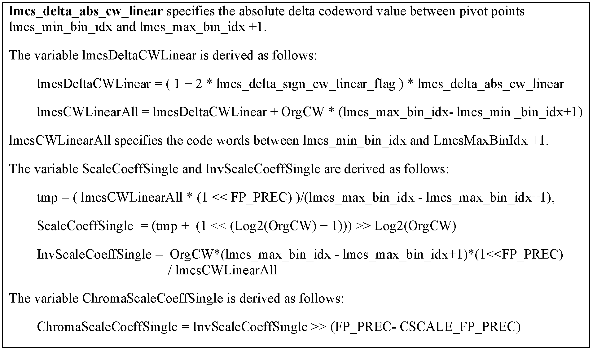
상기 표 19를 참조하면, FP_PREC 및 CSCALE_FP_PREC은 비트 시프팅을 위한 상수들일 수 있다. FP_PREC 및 CSCALE_FP_PREC은 서로 동일하거나 동일하지 않을 수 있다. 예를 들어, FP_PREC는 CSCALE_FP_PREC보다 크거나 같을 수 있다. 일 예에서, FP_PREC 및 CSCALE_FP_PREC은 모두 11일 수 있다. 다른 예에서, FP_PREC은 15이고 그리고 CSCALE_FP_PREC은 11일 수 있다.Referring to Table 19, FP_PREC and CSCALE_FP_PREC may be constants for bit shifting. FP_PREC and CSCALE_FP_PREC may or may not be the same as each other. For example, FP_PREC may be greater than or equal to CSCALE_FP_PREC. In one example, both FP_PREC and CSCALE_FP_PREC may be 11. In another example, FP_PREC may be 15 and CSCALE_FP_PREC may be 11.
상기 표 19에서, lmcs_max_bin_idx는 LmcsMaxBinIdx와 혼용되어 사용될 수 있다. lmcs_max_bin_idx 및 LmcsMaxBinIdx는, 상술된 표 17의 신택스의 lmcs_delta_max_bin_idx를 기반으로 상술된 표 18을 참조하여 도출될 수 있다. 이와 같이, 표 19는 표 18을 참조하여 해석될 수 있다. In Table 19, lmcs_max_bin_idx may be used interchangeably with LmcsMaxBinIdx. The lmcs_max_bin_idx and LmcsMaxBinIdx may be derived with reference to Table 18 described above based on the lmcs_delta_max_bin_idx of the syntax of Table 17 described above. As such, Table 19 can be interpreted with reference to Table 18.
본 문서에 따른 다른 실시예에서, 선형 리셰이퍼를 시그널링하는 방법의 또 다른 예가 제안될 수 있다. 선형 리셰이퍼 모델의 피벗 포인트들 P1, P2는 명시적으로 시그널링될 수 있다. 다음 표들은 본 예시에 따라 선형 리셰이퍼 모델을 명시적으로 시그널링하는 신택스 및 시맨틱스의 일 예를 나타낸다. In another embodiment according to the present document, another example of a method of signaling a linear reshaper may be proposed. The pivot points P1 and P2 of the linear reshaper model can be explicitly signaled. The following tables show an example of syntax and semantics for explicitly signaling a linear reshaper model according to this example.


표 20 및 21을 참조하면, 신택스 요소 lmcs_min_input을 기반으로 제1 피벗 포인트의 입력 값이 도출될 수 있고, 그리고 신택스 요소 lmcs_max_input을 기반으로 제2 피벗 포인트의 입력 값이 도출될 수 있다. 제1 피벗 포인트의 맵핑된 값은 사전에 결정된 값(인코더 및 디코더 모두에 알려진 값)일 수 있고, 예를 들어 0일 수 있다. 신택스 요소 lmcs_max_mapped를 기반으로 제2 피벗 포인트의 맵핑된 값이 도출될 수 있다. 즉, 표 20의 신택스를 기반으로 시그널링된 상기 정보를 기반으로 선형 리셰이퍼 모델이 명시적으로(직접적으로) 시그널링될 수 있다.Referring to Tables 20 and 21, the input value of the first pivot point may be derived based on the syntax element lmcs_min_input, and the input value of the second pivot point may be derived based on the syntax element lmcs_max_input. The mapped value of the first pivot point may be a predetermined value (a value known to both the encoder and the decoder), and may be 0, for example. A mapped value of the second pivot point may be derived based on the syntax element lmcs_max_mapped. That is, the linear reshaper model may be explicitly (directly) signaled based on the information signaled based on the syntax of Table 20.
대안적으로, lmcs_max_input 및 lmcs_max_mapped는 델타 값으로서 시그널링될 수 있다. 다음 표들은 델타 값으로서 선형 리셰이퍼 모델을 시그널링하는 신택스 및 시맨틱스의 일 예를 나타낸다. Alternatively, lmcs_max_input and lmcs_max_mapped can be signaled as delta values. The following tables show an example of syntax and semantics for signaling a linear reshaper model as a delta value.


상기 표 23을 참조하면, 신택스 요소 lmcs_min_input을 기반으로 제1 피벗 포인트의 입력 값이 도출될 수 있다. 예를 들어, lmcs_min_input은 0의 맵핑된 값을 가질 수 있다. lmcs_max_input_delta는 제2 피벗 포인트의 입력 값과 최대 루마 값(i.e., (1<<bitdepthY)-1) 간의 차이를 나타낼 수 있다. lmcs_max_mapped_delta는 제2 피벗 포인트의 맵핑된 값과 최대 루마 값(i.e., (1<<bitdepthY)-1) 간의 차이를 나타낼 수 있다. Referring to Table 23, the input value of the first pivot point may be derived based on the syntax element lmcs_min_input. For example, lmcs_min_input may have a mapped value of 0. lmcs_max_input_delta may represent a difference between the input value of the second pivot point and the maximum luma value (i.e., (1<<bitdepthY)-1). lmcs_max_mapped_delta may represent a difference between the mapped value of the second pivot point and the maximum luma value (i.e., (1<<bitdepthY)-1).
본 문서의 일 실시예에 따르면, 상술된 선형 리셰이퍼에 관한 예시들을 기반으로 루마 예측 샘플들을 위한 포워드 맵핑, 루마 복원 샘플들을 위한 인버스 맵핑, 크로마 레지듀얼 스케일링이 수행될 수 있다. 일 예에서, 선형 리셰이퍼 기반 인버스 맵핑에서 루마 (복원) 샘플들(픽셀들)을 위한 인버스 스케일링을 위해 오직 하나의 인버스 스케일링 팩터가 필요할 수 있다. 이는 포워드 맵핑, 크로마 레지듀얼 스케일링에서도 마찬가지이다. 즉, 빈 인덱스 i에 대한 ScaleCoeff[i], InvScaleCoeff[i] and ChromaScaleCoeff[i]를 결정하는 단계들은 오직 하나의 팩터를 이용하는 것을 대체될 수 있다. 여기서, 하나의 팩터란 선형 맵핑의 (포워드) 기울기 또는 인버스 기울기가 고정 소수점으로 표현된 것을 지칭할 수 있다. 일 예에서, 인버스 루마 맵핑 스케일링 팩터(루마 복원 샘플들을 위한 인버스 맵핑에서의 인버스 스케일링 팩터)는 다음 수학식들 중 적어도 하나를 기반으로 도출될 수 있다.According to an embodiment of the present document, forward mapping for luma prediction samples, inverse mapping for luma reconstructed samples, and chroma residual scaling may be performed based on examples of the linear reshaper described above. In one example, only one inverse scaling factor may be needed for inverse scaling for luma (restored) samples (pixels) in linear reshaper based inverse mapping. This is the same for forward mapping and chroma residual scaling. That is, the steps of determining ScaleCoeff[i], InvScaleCoeff[i] and ChromaScaleCoeff[i] for the bin index i may be replaced with using only one factor. Here, one factor may refer to a (forward) slope or an inverse slope of a linear mapping expressed as a fixed point. In an example, an inverse luma mapping scaling factor (an inverse scaling factor in inverse mapping for luma reconstructed samples) may be derived based on at least one of the following equations.
수학식 17의 lmcsCWLinear는 상술된 표 17 및 18로부터 도출될 수 있다. 수학식 18 및 19의 lmcsCWLinearALL은 상술된 표 19 내지 23 중 적어도 하나로부터 도출될 수 있다. 수학식 17 또는 18에서 OrgCW는 표 8 또는 18로부터 도출될 수 있다.LmcsCWLinear of Equation 17 may be derived from Tables 17 and 18 described above. LmcsCWLinearALL of Equations 18 and 19 may be derived from at least one of Tables 19 to 23 described above. In Equation 17 or 18, OrgCW may be derived from Table 8 or 18.
다음 표들은 픽처 복원에서의 루마 샘플들(i.e. 루마 예측 샘플들)에 대한 포워드 맵핑 절차를 나타내는 수학식들 및 신택스(조건문)를 설명한다. 이하의 표들 및 수학식들에서, FP_PREC은 비트 시프팅을 위한 상수이고, 사전에 결정된 값일 수 있다. 예를 들면, FP_PREC은 11 또는 15일 수 있다.The following tables describe equations and syntax (conditional statements) representing a forward mapping procedure for luma samples (i.e. luma prediction samples) in picture restoration. In the following tables and equations, FP_PREC is a constant for bit shifting and may be a predetermined value. For example, FP_PREC may be 11 or 15.


표 24는 상술된 표 7 및 8에 기반한 루마 맵핑 절차에서 포워드 맵핑된 루마 샘플들을 도출하기 위한 것일 수 있다. 즉, 표 24는 표 7 및 9과 함께 설명될 수 있다. 표 24에서, 입력으로서의 루마 (예측) 샘플들 predSamples[i][j]로부터 출력으로서의 포워드 맵핑된 루마 (예측) 샘플들 PredmAPSamples[i][j]가 도출될 수 있다. 표 24의 idxY는 (포워드) 맵핑 인덱스로 지칭될 수 있고, 맵핑 인덱스는 예측 루마 샘플들을 기반으로 도출될 수 있다.Table 24 may be for deriving forward-mapped luma samples in the luma mapping procedure based on Tables 7 and 8 described above. That is, Table 24 can be described together with Tables 7 and 9. In Table 24, forward mapped luma (prediction) samples PredmAPSamples[i][j] as output can be derived from luma (predictive) samples predSamples[i][j] as input. IdxY of Table 24 may be referred to as a (forward) mapping index, and the mapping index may be derived based on predicted luma samples.
표 25는 선형 리셰이퍼의 적용에 따른 루마 맵핑에서 포워드 맵핑된 루마 샘플들을 도출하기 위한 것일 수 있다. 예를 들어, 표 25의 lmcs_min_input, lmcs_max_input, lmcs_max_mapped, ScaleCoeffSingle은 표 20 내지 23 중 적어도 하나에 의하여 도출될 수 있다. 표 25에서, lmcs_min_input<predSamples[i][j]< lmcs_max_input인 경우에 입력으로서의 루마 (예측) 샘플들 predSamples[i][j]로부터 출력으로서의 포워드 맵핑된 루마 (예측) 샘플들 PredmAPSamples[i][j]가 도출될 수 있다. 표 24와 표 25 간의 비교를 통해, 선형 리셰이퍼의 적용에 따른 기존 LMCS로부터의 변화가 포워드 맵핑 관점에서 보여질 수 있다.Table 25 may be for deriving forward-mapped luma samples from luma mapping according to the application of the linear reshaper. For example, lmcs_min_input, lmcs_max_input, lmcs_max_mapped, and ScaleCoeffSingle of Table 25 may be derived by at least one of Tables 20 to 23. In Table 25, in the case of lmcs_min_input<predSamples[i][j]< lmcs_max_input, luma (prediction) samples as input from predSamples[i][j] to forward mapped luma (prediction) samples as output PredmAPSamples[i][ j] can be derived. Through the comparison between Tables 24 and 25, the change from the existing LMCS according to the application of the linear reshaper can be seen from the perspective of forward mapping.
다음 수학식들은 루마 샘플들(i.e. 루마 복원 샘플들)에 대한 인버스 맵핑 절차를 설명한다. 아래 수학식들에서, 입력으로서의 lumaSample은 인버스 맵핑 이전의(수정 전) 루마 복원 샘플일 수 있다. 출력으로서의 invSample은 인버스 맵핑된(수정된) 루마 복원 샘플일 수 있다. 다른 경우, 클리핑된 invSample가 수정된 루마 복원 샘플로 지칭되기도 할 수 있다. The following equations describe an inverse mapping procedure for luma samples (i.e. luma reconstructed samples). In the following equations, lumaSample as an input may be a luma restoration sample before inverse mapping (before modification). InvSample as output may be an inverse mapped (modified) luma reconstructed sample. In other cases, the clipped invSample may be referred to as a modified luma reconstructed sample.

수학식 20을 참조하면, 인덱스 idxInv는 상술된 표 10을 기반으로 도출될 수 있다. 즉, 수학식 20은 상술된 표 7 및 8에 기반한 루마 맵핑 절차에서 인버스 맵핑된 루마 샘플들을 도출하기 위한 것일 수 있다. 수학식 20은 상술된 표 9와 함께 설명될 수 있다.Referring to Equation 20, the index idxInv may be derived based on Table 10 described above. That is, Equation 20 may be for deriving inverse-mapped luma samples in the luma mapping procedure based on Tables 7 and 8 described above. Equation 20 may be described together with Table 9 described above.
수학식 21은 선형 리셰이퍼의 적용에 따른 루마 맵핑에서 인버스 맵핑된 루마 샘플들을 도출하기 위한 것일 수 있다. 예를 들어, 수학식 21의 lmcs_min_input은 표 20 내지 23 중 적어도 하나에 의하여 도출될 수 있다. 수학식 20과 수학식 21 간의 비교를 통해, 선형 리셰이퍼의 적용에 따른 기존 LMCS로부터의 변화가 포워드 맵핑 관점에서 보여질 수 있다.Equation 21 may be for deriving inverse-mapped luma samples from luma mapping according to the application of a linear reshaper. For example, lmcs_min_input of Equation 21 may be derived by at least one of Tables 20 to 23. Through the comparison between Equation 20 and Equation 21, a change from the existing LMCS according to the application of the linear reshaper can be seen from the viewpoint of forward mapping.
상술된 선형 리셰이퍼에 관한 예시들을 기반으로 피스와이즈 인덱스 식별 절차가 생략될 수 있다. 즉, 본 예시들에서 리셰이프된 루마 픽셀을 갖는 조각이 1개만 존재하기 때문에 인버스 루마 맵핑 및 크로마 레지듀얼 스케일링에 사용되는 피스와이즈 인덱스 식별 절차가 제거될 수 있다. 이에 따라, 인버스 루마 맵핑의 복잡성이 감소될 수 있다. 이에 더하여, 루마 피스와이즈 인덱스 식별에 의존함으로써 야기되는 레이턴시 문제가 크로마 레지듀얼 스케일링 도중에 제거될 수 있다.A piecewise index identification procedure may be omitted based on the above-described examples of the linear reshaper. That is, since there is only one fragment having a reshaped luma pixel in the examples, a piecewise index identification procedure used for inverse luma mapping and chroma residual scaling may be eliminated. Accordingly, the complexity of the inverse luma mapping can be reduced. In addition, the latency problem caused by relying on luma piecewise index identification can be eliminated during chroma residual scaling.
상술된 선형 리셰이퍼의 사용에 관한 실시예에 따라, LMCS를 위해 다음과 같은 이점들이 제공될 수 있다. i) 인코더의 리셰이퍼 설계를 단순화하여 피스와이즈 선형 조각들 사이에서 발생되는 갑작스러운 변화로 인한 열화를 방지할 수 있다. ii) 피스와이즈 인덱스 식별 절차를 제거하여 디코더 인버스 매핑 절차를 단순화할 수 있다. iii) 피스와이즈 인덱스 식별 절차를 제거하여 해당 루마 블록들에 의존함으로써 야기되는 크로마 레지듀얼 스케일링 내의 레이턴시 문제를 제거할 수 있다. iv) 시그널링의 오버헤드를 줄이고, 잦은 리셰이퍼의 업데이트를 보다 실현 가능하게 할 수 있다. v) 16개 조각들의 루프(예컨대, for 구문)가 필요했던 많은 부분들에서 루프를 제거할 수 있다. 예를 들어, InvScaleCoeff[i]를 도출하기 위해 lmcsCW[i]에 의한 나눗셈 연산의 수를 1로 줄일 수 있다.Depending on the embodiment of the use of the linear reshaper described above, the following advantages may be provided for the LMCS. i) By simplifying the encoder's reshaper design, it is possible to prevent deterioration due to sudden changes occurring between the piecewise linear pieces. ii) It is possible to simplify the decoder inverse mapping procedure by removing the piecewise index identification procedure. iii) By removing the peacewise index identification procedure, a latency problem in chroma residual scaling caused by relying on corresponding luma blocks can be eliminated. iv) Reduce the signaling overhead and make frequent reshaper updates more feasible. v) You can remove loops in many areas where a 16-piece loop (eg, for statement) was needed. For example, the number of division operations by lmcsCW[i] can be reduced to 1 to derive InvScaleCoeff[i].
본 문서에 따른 또 다른 실시예에서는 플렉서블한 빈들에 기반한 LMCS가 제안된다. 여기서, 플렉서블한 빈들이란 빈들의 개수가 소정의 수로 고정되지 않음을 의미할 수 있다. 기존의 일 실시예에서는 LMCS에서의 빈들의 개수가 16개로 고정되었고, 그리고 16개의 빈들은 입력 샘플 값들에 대해 균등하게 분포되었다. 본 실시예에서는 플렉서블한 개수의 빈들이 제안되고 그리고 조각(빈)들이 원본 픽셀 값들에 대해 균등하게 분배되지 않을 것이다.In another embodiment according to this document, an LMCS based on flexible beans is proposed. Here, the flexible bins may mean that the number of bins is not fixed to a predetermined number. In an existing embodiment, the number of bins in the LMCS is fixed to 16, and the 16 bins are evenly distributed for input sample values. In this embodiment, a flexible number of bins is proposed, and fragments (bins) will not be evenly distributed to original pixel values.
다음 표들은 본 실시예에 따른 LMCS 데이터에 관한 신택스 및/또는 시맨틱스를 예시적으로 나타낸다.The following tables exemplarily show syntax and/or semantics for LMCS data according to the present embodiment.


표 26을 참조하면, 빈들의 개수에 관한 정보 lmcs_num_bins_minus1가 시그널링될 수 있다. 표 27을 참조하면, lmcs_num_bins_minus1+1은 빈들의 개수와 동일할 수 있고, 이로부터 빈들의 개수는 1부터 (1<<BitDepthY)-1까지의 범위 내에 있을 수 있다. 예를 들어, lmcs_num_bins_minus1 또는 lmcs_num_bins_minus1+1은 2의 배수일 수 있다. Referring to Table 26, information about the number of bins lmcs_num_bins_minus1 may be signaled. Referring to Table 27, lmcs_num_bins_minus1+1 may be equal to the number of bins, and the number of bins may range from 1 to (1<<BitDepthY)-1. For example, lmcs_num_bins_minus1 or lmcs_num_bins_minus1+1 may be a multiple of 2.
표 26 및 27과 함께 설명된 실시예에서, 피벗 포인트들의 개수는, 리셰이퍼가 선형인지 여부와 관계 없이, lmcs_num_bins_minus1(빈들의 개수에 관한 정보)을 기반으로 도출될 수 있고(lmcs_num_bins_minus1의 시그널링) 그리고 피벗 포인트들의 입력 값들 및 맵핑된 값들(LmcsPivot_input[i], LmcsPivot_mapped[i])은 시그널링된 코드워드 값들(lmcs_delta_input_cw[i], lmcs_delta_mapped_cw[i])의 합산을 기반으로 도출될 수 있다(여기서, 초기 입력 값 LmcsPivot_input[0] 및 초기 출력 값 LmcsPivot_mapped[0]은 0). In the embodiment described with Tables 26 and 27, the number of pivot points may be derived based on lmcs_num_bins_minus1 (information on the number of bins), regardless of whether the reshaper is linear or not (signaling of lmcs_num_bins_minus1) and The input values of the pivot points and the mapped values (LmcsPivot_input[i], LmcsPivot_mapped[i]) can be derived based on the summation of the signaled codeword values (lmcs_delta_input_cw[i], lmcs_delta_mapped_cw[i]) (here, the initial The input value LmcsPivot_input[0] and the initial output value LmcsPivot_mapped[0] are 0).
이하의 도면은 본 명세서의 구체적인 일례를 설명하기 위해 작성되었다. 도면에 기재된 구체적인 장치의 명칭이나 구체적인 신호/메시지/필드의 명칭은 예시적으로 제시된 것이므로, 본 명세서의 기술적 특징이 이하의 도면에 사용된 구체적인 명칭에 제한되지 않는다.The following drawings are prepared to explain a specific example of the present specification. Since the names of specific devices or names of specific signals/messages/fields described in the drawings are provided by way of example, technical features of the present specification are not limited to specific names used in the following drawings.
도 12 및 13은 본 문서의 실시예(들)에 따른 비디오/영상 인코딩 방법 및 관련 컴포넌트의 일 예를 개략적으로 나타낸다. 도 12에서 개시된 방법은 도 2에서 개시된 인코딩 장치에 의하여 수행될 수 있다. 구체적으로 예를 들어, 도 12의 S1200는 상기 인코딩 장치의 레지듀얼 처리부(230) 또는 예측부(220)에 의하여 수행될 수 있고, S1210은 상기 인코딩 장치의 예측부(220) 또는 가산부(250)에 의하여 수행될 수 있고, S1220은 상기 인코딩 장치의 레지듀얼 처리부(230) 또는 가산부(250)에 의하여 수행될 수 있고, S1230, S1240 또는 S1250은 상기 인코딩 장치의 레지듀얼 처리부(230)에 의하여 수행될 수 있고, S1260은 상기 인코딩 장치의 엔트로피 인코딩부(240)에 의하여 수행될 수 있다. 도 12에서 개시된 방법은 본 문서에서 상술한 실시예들을 포함할 수 있다.12 and 13 schematically illustrate an example of a video/video encoding method and related components according to the embodiment(s) of this document. The method disclosed in FIG. 12 may be performed by the encoding apparatus disclosed in FIG. 2. Specifically, for example, S1200 of FIG. 12 may be performed by the residual processing unit 230 or the prediction unit 220 of the encoding device, and S1210 is the prediction unit 220 or the addition unit 250 of the encoding device. ), and S1220 may be performed by the residual processing unit 230 or the adding unit 250 of the encoding device, and S1230, S1240 or S1250 may be performed by the residual processing unit 230 of the encoding device. It may be performed by, and S1260 may be performed by the entropy encoding unit 240 of the encoding device. The method disclosed in FIG. 12 may include the embodiments described above in this document.
도 12를 참조하면, 인코딩 장치는 예측 루마 샘플들 및 레지듀얼 크로마 샘플들을 생성할 수 있다(S1200). 예측 루마 샘플들과 관련하여, 인코딩 장치는 예측 모드를 기반으로 상기 현재 블록의 예측 루마 샘플들을 도출할 수 있다. 이 경우 인터 예측 또는 인트라 예측 등 본 문서에서 개시된 다양한 예측 방법이 적용될 수 있다. 유사하게, 인코딩 장치는 예측 크로마 샘플들을 도출할 수 있다. 인코딩 장치는 현재 블록의 원본 크로마 샘플들 및 예측 크로마 샘플들을 기반으로 상기 레지듀얼 크로마 샘플들을 도출할 수 있다. 예를 들어, 인코딩 장치는 상기 예측 크로마 샘플들과 원본 크로마 샘플들 간의 차를 기반으로 레지듀얼 크로마 샘플들을 도출할 수 있다. Referring to FIG. 12, the encoding apparatus may generate predictive luma samples and residual chroma samples (S1200 ). In relation to the prediction luma samples, the encoding apparatus may derive the prediction luma samples of the current block based on the prediction mode. In this case, various prediction methods disclosed in this document, such as inter prediction or intra prediction, may be applied. Similarly, the encoding device can derive predictive chroma samples. The encoding apparatus may derive the residual chroma samples based on the original chroma samples and the predicted chroma samples of the current block. For example, the encoding apparatus may derive residual chroma samples based on a difference between the predicted chroma samples and the original chroma samples.
인코딩 장치는 맵핑된 예측 루마 샘플들을 생성할 수 있다(S1210). 예를 들어, 인코딩 장치는 루마 맵핑을 위한 피벗 포인트들의 입력 값들 및 맵핑 값(출력 값)을 도출할 수 있고 그리고 상기 입력 값들 및 맵핑 값들을 기반으로 맵핑된 예측 루마 샘플들을 생성할 수 있다. 일 예에서, 인코딩 장치는 제1 예측 루마 샘플을 기반으로 맵핑 인덱스(idxY)를 도출할 수 있고 그리고 상기 맵핑 인덱스에 대응하는 피벗 포인트의 입력 값 및 맵핑 값을 기반으로 제1 맵핑된 예측 루마 샘플을 생성할 수 있다. 다른 예에서, 선형 맵핑(선형 리셰이핑, 선형 LMCS) 사용될 수 있고 그리고 선형 맵핑에서의 두 개의 피벗 포인트들로부터 도출된 포워드 맵핑 스켕일링 팩터를 기반으로 맵핑된 예측 루마 샘플들이 생성될 수 있고, 따라서 선형 맵핑으로 인해 인덱스 도출 절차가 생략될 수도 있다.The encoding device may generate mapped prediction luma samples (S1210). For example, the encoding apparatus may derive input values and mapping values (output values) of pivot points for luma mapping, and may generate mapped prediction luma samples based on the input values and mapping values. In one example, the encoding device may derive a mapping index (idxY) based on a first prediction luma sample, and a first mapped prediction luma sample based on an input value and a mapping value of a pivot point corresponding to the mapping index Can be created. In another example, linear mapping (linear reshaping, linear LMCS) can be used and mapped predictive luma samples based on the forward mapping scaling factor derived from the two pivot points in the linear mapping can be generated, and thus The index derivation procedure may be omitted due to linear mapping.
인코딩 장치는 스케일링된 레지듀얼 크로마 샘플들을 생성할 수 있다(S1220). 구체적으로, 인코딩 장치는 크로마 레지듀얼 스케일링 팩터를 도출할 수 있고 크로마 레지듀얼 스케일링 팩터를 기반으로 스케일링된 레지듀얼 크로마 샘플들을 생성할 수 있다. 여기서, 인코딩 단의 크로마 레지듀얼 스케일링은 포워드 크로마 레지듀얼 스케일링으로 지칭될 수도 있다. 따라서, 인코딩 장치에 의하여 도출된 크로마 레지듀얼 스케일링 팩터는 포워드 크로마 레지듀얼 스케일링 팩터로 지칭될 수 있고 포워드 스케일링된 레지듀얼 크로마 샘플들이 생성될 수 있다.The encoding apparatus may generate scaled residual chroma samples (S1220). Specifically, the encoding apparatus may derive a chroma residual scaling factor and generate scaled residual chroma samples based on the chroma residual scaling factor. Here, chroma residual scaling of the encoding stage may be referred to as forward chroma residual scaling. Accordingly, the chroma residual scaling factor derived by the encoding apparatus may be referred to as a forward chroma residual scaling factor, and forward-scaled residual chroma samples may be generated.
인코딩 장치는 맵핑된 예측 루마 샘플들 및 스케일링된 레지듀얼 크로마 샘플들을 기반으로 LMCS 관련 정보를 도출할 수 있다(S1230). 인코딩 장치는 상기 복원 샘플들에 대한 LMCS 관련 정보를 생성할 수 있다. 인코딩 장치는 상기 복원 샘플들에 대한 필터링을 위하여 적용될 수 있는 LMCS 관련 파라미터를 도출하고, LMCS 관련 파라미터들을 기반으로 LMCS 관련 정보를 생성할 수 있다. 예를 들어, LMCS 관련 정보는 상술된 루마 맵핑(ex. 포워드 맵핑, 인버스 맵핑, 선형 맵핑)에 관한 정보, 크로마 레지듀얼 스케일링에 관한 정보, 및/또는 LMCS(또는 리셰이핑, 리셰이퍼)에 관련된 인덱스들(ex. 최대 빈 인덱스, 최소 빈 인덱스)을 포함할 수 있다.The encoding apparatus may derive LMCS-related information based on the mapped prediction luma samples and the scaled residual chroma samples (S1230). The encoding device may generate LMCS related information for the reconstructed samples. The encoding apparatus may derive LMCS-related parameters that can be applied to filter the reconstructed samples, and may generate LMCS-related information based on the LMCS-related parameters. For example, the LMCS-related information is information on luma mapping (ex.forward mapping, inverse mapping, linear mapping), information on chroma residual scaling, and/or LMCS (or reshaping, reshaper). It may include indexes (ex. a maximum bin index, a minimum bin index).
인코딩 장치는 상기 맵핑된 예측 루마 샘플들을 기반으로 레지듀얼 루마 샘플들을 생성할 수 있다(S1240). 예를 들어, 인코딩 장치는 상기 맵핑된 예측 루마 샘플들과 원본 루마 샘플들 간의 차를 기반으로 레지듀얼 루마 샘플들을 도출할 수 있다.The encoding apparatus may generate residual luma samples based on the mapped prediction luma samples (S1240). For example, the encoding apparatus may derive residual luma samples based on a difference between the mapped prediction luma samples and original luma samples.
인코딩 장치는 상기 스케일링된 레지듀얼 크로마 샘플들 및 상기 레지듀얼 루마 샘플들을 기반으로 레지듀얼 정보를 도출할 수 있다(S1250). 인코딩 장치는 상기 스케일링된 레지듀얼 크로마 샘플들 및 상기 루마 레지듀얼 샘플들에 대한 변환 절차를 기반으로 변환 계수들을 도출할 수 있다. 예를 들어, 변환 절차는 DCT, DST, GBT, 또는 CNT 중 적어도 하나를 포함할 수 있다. 인코딩 장치는 상기 변환 계수들에 대한 양자화 절차를 기반으로 양자화된 변환 계수들을 도출할 수 있다. 양자화된 변환 계수들은 계수 스캔 순서를 기반으로 1차원 벡터 형태를 가질 수 있다. 인코딩 장치는 상기 양자화된 변환 계수들을 나타내는 레지듀얼 정보를 생성할 수 있다. 레지듀얼 정보는 지수 골롬, CAVLC, CABAC 등과 같은 다양한 인코딩 방법을 통해 생성될 수 있다.The encoding apparatus may derive residual information based on the scaled residual chroma samples and the residual luma samples (S1250). The encoding apparatus may derive transform coefficients based on the scaled residual chroma samples and a transform procedure for the luma residual samples. For example, the conversion procedure may include at least one of DCT, DST, GBT, or CNT. The encoding apparatus may derive quantized transform coefficients based on a quantization procedure for the transform coefficients. The quantized transform coefficients may have a one-dimensional vector shape based on the coefficient scan order. The encoding apparatus may generate residual information indicating the quantized transform coefficients. The residual information may be generated through various encoding methods such as exponential Golomb, CAVLC, CABAC, and the like.
인코딩 장치는 영상/비디오 정보를 인코딩할 수 있다(S1260). 상기 영상 정보는 LMCS 관련 정보 및/또는 레지듀얼 정보를 포함할 수 있다. 예를 들면, LMCS 관련 정보는 선형 맵핑에 관한 정보를 포함할 수 있다. 일 예에서, 선형 맵핑에 관한 정보를 기반으로 적어도 하나의 LMCS 코드워드가 도출될 수 있다. 인코딩된 비디오/영상 정보는 비트스트림 형태로 출력될 수 있다. 상기 비트스트림은 네트워크 또는 저장매체를 통하여 디코딩 장치로 전송될 수 있다. The encoding device may encode image/video information (S1260). The image information may include LMCS related information and/or residual information. For example, the LMCS-related information may include information on linear mapping. In an example, at least one LMCS codeword may be derived based on information about linear mapping. The encoded video/video information may be output in the form of a bitstream. The bitstream may be transmitted to a decoding device through a network or a storage medium.
상기 영상/비디오 정보는 본 문서의 실시예에 따른 다양한 정보를 포함할 수 있다. 예를 들어, 상기 영상/비디오 정보는 상술한 표 1, 3, 4, 7, 14, 15, 16 또는 17, 20, 22 또는 26 중 적어도 하나에 개시된 정보를 포함할 수 있다.The image/video information may include various information according to an embodiment of the present document. For example, the image/video information may include information disclosed in at least one of Tables 1, 3, 4, 7, 14, 15, 16 or 17, 20, 22, or 26 described above.
일 실시예에서, 상기 LMCS 관련 정보는 선형 LMCS에 관한 정보를 포함하고 그리고 선형 LMCS에 관한 정보를 기반으로 상기 맵핑된 예측 루마 샘플들이 생성될 수 있다.In an embodiment, the LMCS-related information includes information on a linear LMCS, and the mapped prediction luma samples may be generated based on the information on the linear LMCS.
일 실시예에서, 상기 스케일링된 레지듀얼 크로마 샘플들을 생성하는 단계는 단일 크로마 레지듀얼 스케일링 팩터를 도출하는 단계, 및 상기 레지듀얼 크로마 샘플들 및 상기 단일 크로마 레지듀얼 스케일링 팩터를 기반으로 상기 스케일링된 레지듀얼 크로마 샘플들을 생성하는 단계를 포함할 수 있다. 일 예에서, 상기 영상 정보는 상기 단일 크로마 레지듀얼 스케일링 팩터에 관한 정보를 포함하고, 상기 단일 크로마 레지듀얼 스케일링 팩터에 관한 정보의 값은 상기 단일 크로마 레지듀얼 스케일링 팩터의 값과 동일할 수 있다. 다른 예에서, 상기 단일 크로마 레지듀얼 스케일링 팩터는 상술된 표 12, 13, 18, 19, 21, 23에 포함된 적어도 하나의 수학식, 또는 수학식 5, 6, 9, 10, 11 또는 12를 기반으로 도출될 수 있다. 단일 크로마 레지듀얼 스케일링 팩터 기반 복원 크로마 샘플들 도출을 통해, 크로마 블록에서의 스케일링은 루마 블록 값에 의존하지 않게 되고 피스와이즈 인덱스 식별이 필요하지 않을 수 있다. 따라서 레이턴시 이슈 없이 LMCS에서의 크로마 레지듀얼 스케일링 절차가 수행될 수 있다. In an embodiment, the generating of the scaled residual chroma samples includes deriving a single chroma residual scaling factor, and the scaled residual based on the residual chroma samples and the single chroma residual scaling factor. Generating dual chroma samples may be included. In one example, the image information includes information on the single chroma residual scaling factor, and a value of the information on the single chroma residual scaling factor may be the same as a value of the single chroma residual scaling factor. In another example, the single chroma residual scaling factor is at least one equation included in Tables 12, 13, 18, 19, 21, and 23 described above, or equations 5, 6, 9, 10, 11 or 12. It can be derived on the basis of. Through derivation of reconstructed chroma samples based on a single chroma residual scaling factor, scaling in a chroma block does not depend on a luma block value, and piecewise index identification may not be required. Therefore, a chroma residual scaling procedure in LMCS can be performed without latency issues.
일 실시예에서, 상기 선형 맵핑에 관한 정보는 제1 피벗 포인트(ex. 도 11의 P1)에 관한 정보 및 제2 피벗 포인트(ex. 도 11의 P2)에 관한 정보를 포함할 수 있다. 예를 들어, 상기 제1 피벗 포인트의 입력 값 및 맵핑 값은 각각 최소 입력 값, 최소 맵핑 값일 수 있다. 상기 제2 피벗 포인트의 입력 값 및 맵핑 값은 각각 최대 입력 값, 최대 맵핑 값일 수 있다. 상기 최소 입력 값 및 상기 최대 입력 값 사이의 입력 값은 선형적으로 맵핑될 수 있다.In an embodiment, the information on the linear mapping may include information on a first pivot point (eg, P1 in FIG. 11) and information on a second pivot point (eg, P2 in FIG. 11 ). For example, the input value and the mapping value of the first pivot point may be a minimum input value and a minimum mapping value, respectively. The input value and the mapping value of the second pivot point may be a maximum input value and a maximum mapping value, respectively. An input value between the minimum input value and the maximum input value may be linearly mapped.
일 실시예에서, 상기 영상 정보는 상기 최대 입력 값에 관한 정보 및 상기 최대 맵핑 값에 관한 정보를 포함할 수 있다. 상기 최대 입력 값은 상기 최대 입력 값에 관한 정보(ex. 표 20의 lmcs_max_input)의 값과 동일할 수 있다. 상기 최대 맵핑 값은 상기 최대 맵핑 값에 관한 정보(ex. 표 20의 lmcs_max_mapped)의 값과 동일할 수 있다.In an embodiment, the image information may include information on the maximum input value and information on the maximum mapping value. The maximum input value may be the same as a value of information on the maximum input value (ex. lmcs_max_input in Table 20). The maximum mapping value may be the same as a value of information about the maximum mapping value (ex. lmcs_max_mapped in Table 20).
일 실시예에서, 상기 선형 맵핑에 관한 정보는 상기 제2 피벗 포인트의 입력 델타 값에 관한 정보(ex. 표 22의 lmcs_max_input_delta) 및 상기 제2 피벗 포인트의 맵핑 델타 값에 관한 정보(ex. 표 22의 lmcs_max_mapped_delta)를 포함할 수 있다. 상기 제2 피벗 포인트의 입력 델타 값을 기반으로 상기 최대 입력 값이 도출되고, 상기 제2 피벗 포인트의 맵핑 델타 값을 기반으로 상기 최대 맵핑 값이 도출될 수 있다.In an embodiment, the information on the linear mapping includes information on an input delta value of the second pivot point (ex. lmcs_max_input_delta in Table 22) and information on a mapping delta value of the second pivot point (ex. Table 22). Lmcs_max_mapped_delta) may be included. The maximum input value may be derived based on the input delta value of the second pivot point, and the maximum mapping value may be derived based on the mapping delta value of the second pivot point.
일 실시예에서, 상기 최대 입력 값 및 상기 최대 맵핑 값은 상술된 표 23에 포함된 적어도 하나의 수학식을 기반으로 도출될 수 있다.In an embodiment, the maximum input value and the maximum mapping value may be derived based on at least one equation included in Table 23 described above.
일 실시예에서, 상기 맵핑된 예측 루마 샘플들을 생성하는 단계는, 상기 예측 루마 샘플들에 대한 포워드 맵핑 스케일링 팩터(ex. 상술된 ScaleCoeffSingle)를 도출하는 단계, 및 상기 포워드 맵핑 스케일링 팩터를 기반으로 상기 맵핑된 예측 루마 샘플들은 생성하는 단계를 포함할 수 있다. 상기 포워드 맵핑 스케일링 팩터는 상기 예측 루마 샘플들을 위한 단일 팩터일 수 있다.In an embodiment, the generating of the mapped prediction luma samples includes deriving a forward mapping scaling factor (ex. ScaleCoeffSingle described above) for the prediction luma samples, and the forward mapping scaling factor based on the forward mapping scaling factor. The mapped predictive luma samples may include generating. The forward mapping scaling factor may be a single factor for the prediction luma samples.
일 실시예에서, 상기 포워드 맵핑 스케일링 팩터는 상술된 표 21 및/또는 23에 포함된 적어도 하나의 수학식을 기반으로 도출될 수 있다.In one embodiment, the forward mapping scaling factor may be derived based on at least one equation included in Tables 21 and/or 23 described above.
일 실시예에서, 상기 맵핑된 예측 루마 샘플들은 상술된 표 25에 포함된 적어도 하나의 수학식을 기반을 도출될 수 있다. In an embodiment, the mapped prediction luma samples may be derived based on at least one equation included in Table 25 described above.
일 실시예에서, 인코딩 장치는 상기 복원 루마 샘플들(ex. 상술된 lumaSample)에 대한 인버스 맵핑 스케일링 팩터(ex. 상술된 InvScaleCoeffSingle)를 도출할 수 있다. 또한, 인코딩 장치는 상기 복원 루마 샘플들 및 상기 인버스 맵핑 스케일링 팩터를 기반으로 수정된 복원 루마 샘플들(ex. invSample)을 생성할 수 있다. 상기 인버스 맵핑 스케일링 팩터는 상기 복원 루마 샘플들을 위한 단일 팩터일 수 있다.In an embodiment, the encoding apparatus may derive an inverse mapping scaling factor (eg, InvScaleCoeffSingle) for the reconstructed luma samples (eg, the aforementioned lumaSample). In addition, the encoding apparatus may generate reconstructed luma samples (ex. invSample) modified based on the reconstructed luma samples and the inverse mapping scaling factor. The inverse mapping scaling factor may be a single factor for the reconstructed luma samples.
일 실시예에서, 상기 인버스 맵핑 스케일링 팩터는 상술된 표 18, 19, 21, 23에 포함된 적어도 하나의 수학식, 또는 수학식 11 또는 12를 기반으로 도출될 수 있다.In an embodiment, the inverse mapping scaling factor may be derived based on at least one equation or equation 11 or 12 included in Tables 18, 19, 21, and 23 described above.
일 실시예에서, 상기 수정된 복원 루마 샘플들은 상술된 수학식 21을 기반으로 도출될 수 있다.In an embodiment, the modified reconstructed luma samples may be derived based on Equation 21 described above.
일 실시예에서, 상기 LMCS 관련 정보는 상기 맵핑된 예측 루마 샘플들을 도출하기 위한 빈들의 개수에 관한 정보(ex. 표 26의 lmcs_num_bins_minus1)를 포함할 수 있다. 예를 들어, 루마 맵핑을 위한 피벗 포인트들의 개수는 상기 빈들의 개수와 동일하게 설정될 수 있다. 일 예에서, 인코딩 장치는 상기 빈들의 개수만큼 상기 피벗 포인트들의 델타 입력 값들 및 델타 맵핑 값들을 각각 생성할 수 있다. 일 예에서, 상기 델타 입력 값들(ex. 표 26의 lmcs_delta_input_cw[i]) 및 상기 델타 맵핑 값들(ex. 표 26의 lmcs_delta_mapped_cw[i])을 기반으로 상기 피벗 포인트들의 입력 값들 및 맵핑 값들이 도출되고, 상기 입력 값들(ex. 표 27의 LmcsPivot_input[i], 또는 표 8의 InputPivot[i]) 및 상기 맵핑 값들(ex. 표 27의 LmcsPivot_mapped[i], 또는 표 8의 LmcsPivot[i])을 기반으로 상기 맵핑된 예측 루마 샘플들이 생성될 수 있다.In an embodiment, the LMCS-related information may include information on the number of bins for deriving the mapped prediction luma samples (ex. lmcs_num_bins_minus1 in Table 26). For example, the number of pivot points for luma mapping may be set equal to the number of bins. In an example, the encoding apparatus may generate delta input values and delta mapping values of the pivot points as much as the number of bins. In an example, input values and mapping values of the pivot points are derived based on the delta input values (ex. lmcs_delta_input_cw[i] in Table 26) and the delta mapping values (ex. lmcs_delta_mapped_cw[i] in Table 26). , Based on the input values (ex. LmcsPivot_input[i] of Table 27, or InputPivot[i] of Table 8) and the mapping values (ex. LmcsPivot_mapped[i] of Table 27, or LmcsPivot[i] of Table 8) As a result, the mapped prediction luma samples may be generated.
일 실시예에서, 인코딩 장치는 상기 LMCS 관련 정보에 포함된 적어도 하나의 LMCS 코드워드와 원본 코드워드(OrgCW)를 기반으로 LMCS 델타 코드워드를 도출할 수 있고, 적어도 하나의 LMCS 코드워드와 원본 코드워드를 기반으로 맵핑된 루마 예측 샘플들을 도출할 수도 있다. 일 예에서, 상기 선형 맵핑에 관한 정보는 LMCS 델타 코드워드에 관한 정보를 포함할 수 있다.In one embodiment, the encoding device may derive an LMCS delta codeword based on at least one LMCS codeword and an original codeword (OrgCW) included in the LMCS-related information, and at least one LMCS codeword and an original code Mapped luma prediction samples may be derived based on the word. In one example, the information on the linear mapping may include information on an LMCS delta codeword.
일 실시예에서, 상기 LMCS 델타 코드워드와 OrgCW의 합산을 기반으로 상기 적어도 하나의 LMCS 코드워드가 도출될 수 있고, 예를 들어 OrgCW는 (1<<BitDepthY) / 16 이고, 여기서 BitDepthY는 루마 비트 심도를 나타낼 수 있다. 본 실시예는 수학식 12에 기반할 수 있다.In one embodiment, the at least one LMCS codeword may be derived based on the sum of the LMCS delta codeword and OrgCW, for example, OrgCW is (1<<BitDepthY) / 16, where BitDepthY is luma bit Depth can be indicated. This embodiment may be based on Equation 12.
일 실시예에서, 상기 LMCS 델타 코드워드와 OrgCW*(lmcs_max_bin_idx-lmcs_min_bin_idx+1)의 합산을 기반으로 상기 적어도 하나의 LMCS 코드워드가 도출될 수 있고, lmcs_max_bin_idx 및 lmcs_min_bin_idx는 각각 최대 빈 인덱스 및 최소 빈 인덱스이고, OrgCW는 (1<<BitDepthY) / 16 일 수 있다. 본 실시예는 수학식 15, 16에 기반할 수 있다.In one embodiment, the at least one LMCS codeword may be derived based on the sum of the LMCS delta codeword and OrgCW* (lmcs_max_bin_idx-lmcs_min_bin_idx+1), and lmcs_max_bin_idx and lmcs_min_bin_idx are respectively a maximum bin index and a minimum bin index And OrgCW may be (1<<BitDepthY) / 16. This embodiment may be based on Equations 15 and 16.
일 실시예에서, 상기 적어도 하나의 LMCS 코드워드는 2의 배수일 수 있다.In one embodiment, the at least one LMCS codeword may be a multiple of 2.
일 실시예에서, 상기 복원 루마 샘플들의 루마 비트 심도(BitDepthY)가 10보다 높은 경우, 상기 적어도 하나의 LMCS 코드워드는 1<<(BitDepthY-10)의 배수일 수 있다.In an embodiment, when the luma bit depth (BitDepthY) of the reconstructed luma samples is higher than 10, the at least one LMCS codeword may be a multiple of 1<<(BitDepthY-10).
일 실시예에서, 상기 적어도 하나의 LMCS 코드워드는 (OrgCW>>1)에서 (OrgCW<<1)-1까지의 범위 내에 있을 수 있다.In one embodiment, the at least one LMCS codeword may be in a range from (OrgCW>>1) to (OrgCW<<1)-1.
도 14 및 15은 본 문서의 실시예에 따른 영상/비디오 디코딩 방법 및 관련 컴포넌트의 일 예를 개략적으로 나타낸다. 도 14에서 개시된 방법은 도 3에서 개시된 디코딩 장치에 의하여 수행될 수 있다. 구체적으로 예를 들어, 도 14의 S1400은 상기 디코딩 장치의 엔트로피 디코딩부(310)에 의하여 수행될 수 있고, S1410은 상기 디코딩 장치의 예측부(330)에 의하여 수행될 수 있고, S1420은 상기 디코딩 장치의 레지듀얼 처리부(320)에 의하여 수행될 수 있고, S1430은 상기 디코딩 장치의 레지듀얼 처리부(320), 예측부(330) 및/또는 가산부(340)에 수행될 수 있고, S1440은 상기 디코딩 장치의 가산부(340)에 의하여 수행될 수 있고, S1450은 상기 디코딩 장치의 레지듀얼 처리부(320) 또는 가산부(340)에 의하여 수행될 수 있고, S1460은 상기 디코딩 장치의 가산부(340)에 의하여 수행될 수 있다. 도 15에서 개시된 방법은 본 문서에서 상술한 실시예들을 포함할 수 있다. 14 and 15 schematically illustrate an example of a video/video decoding method and related components according to an embodiment of the present document. The method disclosed in FIG. 14 may be performed by the decoding apparatus disclosed in FIG. 3. Specifically, for example, S1400 of FIG. 14 may be performed by the entropy decoding unit 310 of the decoding device, S1410 may be performed by the prediction unit 330 of the decoding device, and S1420 is the decoding It may be performed by the residual processing unit 320 of the device, and S1430 may be performed by the residual processing unit 320, the prediction unit 330 and/or the addition unit 340 of the decoding device, and S1440 is the It may be performed by the adding unit 340 of the decoding device, S1450 may be performed by the residual processing unit 320 or the adding unit 340 of the decoding device, and S1460 may be performed by the adding unit 340 of the decoding device. ) Can be performed. The method disclosed in FIG. 15 may include the embodiments described above in this document.
도 14를 참조하면, 디코딩 장치는 비디오/영상 정보를 수신/획득할 수 있다 (S1400). 비디오/영상 정보는 LMCS 관련 정보를 포함할 수 있다. 예를 들어, LMCS 관련 정보는 상술된 루마 맵핑(ex. 포워드 맵핑, 인버스 맵핑, 선형 맵핑)에 관한 정보, 크로마 레지듀얼 스케일링에 관한 정보, 및/또는 LMCS(또는 리셰이핑, 리셰이퍼)에 관련된 인덱스들(ex. 최대 빈 인덱스, 최소 빈 인덱스, 맵핑 인덱스)을 포함할 수 있다. 디코딩 장치는 비트스트림을 통하여 상기 영상/비디오 정보를 수신/획득할 수 있다.Referring to FIG. 14, the decoding apparatus may receive/obtain video/video information (S1400). The video/video information may include LMCS-related information. For example, the LMCS-related information is information on luma mapping (ex.forward mapping, inverse mapping, linear mapping), information on chroma residual scaling, and/or LMCS (or reshaping, reshaper). Indices (ex. maximum bin index, minimum bin index, mapping index) may be included. The decoding apparatus may receive/acquire the image/video information through a bitstream.
상기 영상/비디오 정보는 본 문서의 실시예에 따른 다양한 정보를 포함할 수 있다. 예를 들어, 상기 영상/비디오 정보는 상술한 표 1, 3, 4, 7, 14, 15, 16 또는 17, 20, 22 또는 26 중 적어도 하나에 개시된 정보를 포함할 수 있다.The image/video information may include various information according to an embodiment of the present document. For example, the image/video information may include information disclosed in at least one of Tables 1, 3, 4, 7, 14, 15, 16 or 17, 20, 22, or 26 described above.
디코딩 장치는 예측 루마 샘플들을 생성할 수 있다(S1410). 디코딩 장치는 예측 모드를 기반으로 상기 현재 블록의 예측 루마 샘플들을 도출할 수 있다. 이 경우 인터 예측 또는 인트라 예측 등 본 문서에서 개시된 다양한 예측 방법이 적용될 수 있다.The decoding apparatus may generate predicted luma samples (S1410). The decoding apparatus may derive prediction luma samples of the current block based on the prediction mode. In this case, various prediction methods disclosed in this document, such as inter prediction or intra prediction, may be applied.
디코딩 장치는 레지듀얼 정보를 기반으로 레지듀얼 크로마 샘플들을 생성할 수 있다(S1420). 구체적으로, 디코딩 장치는 레지듀얼 정보를 기반으로 양자화된 변환 계수들을 도출할 수 있다. 양자화된 변환 계수들은 계수 스캔 순서를 기반으로 1차원 벡터 형태를 가질 수 있다. 디코딩 장치는 상기 양자화된 변환 계수들에 대한 역양자화 절차를 기반으로 변환 계수들을 도출할 수 있다. 디코딩 장치는 변환 계수들을 기반으로 레지듀얼 크로마 샘플들 및/또는 레지듀얼 루마 샘플들을 도출할 수 있다.The decoding apparatus may generate residual chroma samples based on the residual information (S1420). Specifically, the decoding apparatus may derive quantized transform coefficients based on the residual information. The quantized transform coefficients may have a one-dimensional vector shape based on the coefficient scan order. The decoding apparatus may derive transform coefficients based on an inverse quantization procedure for the quantized transform coefficients. The decoding apparatus may derive residual chroma samples and/or residual luma samples based on the transform coefficients.
디코딩 장치는 맵핑된 예측 루마 샘플들을 생성할 수 있다(S1430). 예를 들어, 디코딩 장치는 루마 맵핑을 위한 피벗 포인트들의 입력 값들 및 맵핑 값(출력 값)을 도출할 수 있고 그리고 상기 입력 값들 및 맵핑 값들을 기반으로 맵핑된 예측 루마 샘플들을 생성할 수 있다. 일 예에서, 디코딩 장치는 제1 예측 루마 샘플을 기반으로 (포워드) 맵핑 인덱스(idxY)를 도출할 수 있고 그리고 상기 맵핑 인덱스에 대응하는 피벗 포인트의 입력 값 및 맵핑 값을 기반으로 제1 맵핑된 예측 루마 샘플을 생성할 수 있다. 다른 예에서, 선형 맵핑(선형 리셰이핑, 선형 LMCS) 사용될 수 있고 그리고 선형 맵핑에서의 두 개의 피벗 포인트들로부터 도출된 포워드 맵핑 스켕일링 팩터를 기반으로 맵핑된 예측 루마 샘플들이 생성될 수 있고, 따라서 선형 맵핑으로 인해 인덱스 도출 절차가 생략될 수도 있다.The decoding apparatus may generate mapped prediction luma samples (S1430). For example, the decoding apparatus may derive input values and mapping values (output values) of pivot points for luma mapping, and may generate mapped prediction luma samples based on the input values and mapping values. In one example, the decoding apparatus may derive a (forward) mapping index (idxY) based on the first predicted luma sample, and the first mapped based on the input value and the mapping value of the pivot point corresponding to the mapping index. Predictive luma samples can be generated. In another example, linear mapping (linear reshaping, linear LMCS) can be used and mapped predictive luma samples based on the forward mapping scaling factor derived from the two pivot points in the linear mapping can be generated, and thus The index derivation procedure may be omitted due to linear mapping.
디코딩 장치는 복원 루마 샘플들을 생성할 수 있다(S1440). 디코딩 장치는 맵핑된 예측 루마 샘플들을 기반으로 복원 루마 샘플들을 생성할 수 있다. 구체적으로, 디코딩 장치는 상술된 레지듀얼 루마 샘플들을 맵핑된 예측 루마 샘플들과 합산할 수 있고 상기 합산 결과를 기반으로 복원 루마 샘플들을 생성할 수 있다.The decoding apparatus may generate reconstructed luma samples (S1440). The decoding apparatus may generate reconstructed luma samples based on the mapped prediction luma samples. Specifically, the decoding apparatus may sum the above-described residual luma samples with the mapped prediction luma samples, and may generate reconstructed luma samples based on the summation result.
디코딩 장치는 스케일링된 레지듀얼 크로마 샘플들을 생성할 수 있다(S1450). 구체적으로, 디코딩 장치는 크로마 레지듀얼 스케일링 팩터를 도출할 수 있고 크로마 레지듀얼 스케일링 팩터를 기반으로 스케일링된 레지듀얼 크로마 샘플들을 생성할 수 있다. 여기서, 디코딩 단의 크로마 레지듀얼 스케일링은, 인코딩 단과는 반대로, 인버스 크로마 레지듀얼 스케일링으로 지칭될 수도 있다. 따라서, 디코딩 장치에 의하여 도출된 크로마 레지듀얼 스케일링 팩터는 인버스 크로마 레지듀얼 스케일링 팩터로 지칭될 수 있고 인버스 스케일링된 레지듀얼 크로마 샘플들이 생성될 수 있다.The decoding apparatus may generate scaled residual chroma samples (S1450). Specifically, the decoding apparatus may derive a chroma residual scaling factor and generate scaled residual chroma samples based on the chroma residual scaling factor. Here, the chroma residual scaling of the decoding stage may be referred to as inverse chroma residual scaling, as opposed to the encoding stage. Accordingly, the chroma residual scaling factor derived by the decoding apparatus may be referred to as an inverse chroma residual scaling factor, and inverse-scaled residual chroma samples may be generated.
디코딩 장치는 복원 크로마 샘플들을 생성할 수 있다(S1460). 디코딩 장치는 스케일링된 레지듀얼 크로마 샘플들을 기반으로 복원 크로마 샘플들을 생성할 수 있다. 구체적으로, 디코딩 장치는 크로마 성분에 대한 예측 절차를 수행할 수 있고 예측 크로마 샘플들을 생성할 수 있다. 디코딩 장치는 예측 크로마 샘플들과 스케일링된 레지듀얼 크로마 샘플들 간의 합산을 기반으로 복원 크로마 샘플들을 생성할 수 있다. The decoding apparatus may generate reconstructed chroma samples (S1460). The decoding apparatus may generate reconstructed chroma samples based on the scaled residual chroma samples. Specifically, the decoding apparatus may perform a prediction procedure on a chroma component and may generate predicted chroma samples. The decoding apparatus may generate reconstructed chroma samples based on the summation between the predicted chroma samples and the scaled residual chroma samples.
일 실시예에서, 상기 LMCS 관련 정보는 선형 LMCS에 관한 정보를 포함하고 그리고 선형 LMCS에 관한 정보를 기반으로 상기 맵핑된 예측 루마 샘플들이 생성될 수 있다.In an embodiment, the LMCS-related information includes information on a linear LMCS, and the mapped prediction luma samples may be generated based on the information on the linear LMCS.
일 실시예에서, 상기 스케일링된 레지듀얼 크로마 샘플들을 생성하는 단계는 단일 크로마 레지듀얼 스케일링 팩터를 도출하는 단계, 및 상기 레지듀얼 크로마 샘플들 및 상기 단일 크로마 레지듀얼 스케일링 팩터를 기반으로 상기 스케일링된 레지듀얼 크로마 샘플들을 생성하는 단계를 포함할 수 있다. 일 예에서, 상기 영상 정보는 상기 단일 크로마 레지듀얼 스케일링 팩터에 관한 정보를 포함하고, 상기 단일 크로마 레지듀얼 스케일링 팩터에 관한 정보의 값은 상기 단일 크로마 레지듀얼 스케일링 팩터의 값과 동일할 수 있다. 다른 예에서, 상기 단일 크로마 레지듀얼 스케일링 팩터는 상술된 표 12, 13, 18, 19, 21, 23에 포함된 적어도 하나의 수학식, 또는 수학식 5, 6, 9, 10, 11 또는 12를 기반으로 도출될 수 있다. 단일 크로마 레지듀얼 스케일링 팩터 기반 복원 크로마 샘플들 도출을 통해, 크로마 블록에서의 스케일링은 루마 블록 값에 의존하지 않게 되고 피스와이즈 인덱스 식별이 필요하지 않을 수 있다. 따라서 레이턴시 이슈 없이 LMCS에서의 크로마 레지듀얼 스케일링 절차가 수행될 수 있다. In an embodiment, the generating of the scaled residual chroma samples includes deriving a single chroma residual scaling factor, and the scaled residual based on the residual chroma samples and the single chroma residual scaling factor. Generating dual chroma samples may be included. In one example, the image information includes information on the single chroma residual scaling factor, and a value of the information on the single chroma residual scaling factor may be the same as a value of the single chroma residual scaling factor. In another example, the single chroma residual scaling factor is at least one equation included in Tables 12, 13, 18, 19, 21, and 23 described above, or equations 5, 6, 9, 10, 11 or 12. It can be derived on the basis of. Through derivation of reconstructed chroma samples based on a single chroma residual scaling factor, scaling in a chroma block does not depend on a luma block value, and piecewise index identification may not be required. Therefore, a chroma residual scaling procedure in LMCS can be performed without latency issues.
일 실시예에서, 상기 선형 맵핑에 관한 정보는 제1 피벗 포인트(ex. 도 11의 P1)에 관한 정보 및 제2 피벗 포인트(ex. 도 11의 P2)에 관한 정보를 포함할 수 있다. 예를 들어, 상기 제1 피벗 포인트의 입력 값 및 맵핑 값은 각각 최소 입력 값, 최소 맵핑 값일 수 있다. 상기 제2 피벗 포인트의 입력 값 및 맵핑 값은 각각 최대 입력 값, 최대 맵핑 값일 수 있다. 상기 최소 입력 값 및 상기 최대 입력 값 사이의 입력 값은 선형적으로 맵핑될 수 있다.In an embodiment, the information on the linear mapping may include information on a first pivot point (eg, P1 in FIG. 11) and information on a second pivot point (eg, P2 in FIG. 11 ). For example, the input value and the mapping value of the first pivot point may be a minimum input value and a minimum mapping value, respectively. The input value and the mapping value of the second pivot point may be a maximum input value and a maximum mapping value, respectively. An input value between the minimum input value and the maximum input value may be linearly mapped.
일 실시예에서, 상기 영상 정보는 상기 최대 입력 값에 관한 정보 및 상기 최대 맵핑 값에 관한 정보를 포함할 수 있다. 상기 최대 입력 값은 상기 최대 입력 값에 관한 정보(ex. 표 20의 lmcs_max_input)의 값과 동일할 수 있다. 상기 최대 맵핑 값은 상기 최대 맵핑 값에 관한 정보(ex. 표 20의 lmcs_max_mapped)의 값과 동일할 수 있다.In an embodiment, the image information may include information on the maximum input value and information on the maximum mapping value. The maximum input value may be the same as a value of information on the maximum input value (ex. lmcs_max_input in Table 20). The maximum mapping value may be the same as a value of information about the maximum mapping value (ex. lmcs_max_mapped in Table 20).
일 실시예에서, 상기 선형 맵핑에 관한 정보는 상기 제2 피벗 포인트의 입력 델타 값에 관한 정보(ex. 표 22의 lmcs_max_input_delta) 및 상기 제2 피벗 포인트의 맵핑 델타 값에 관한 정보(ex. 표 22의 lmcs_max_mapped_delta)를 포함할 수 있다. 상기 제2 피벗 포인트의 입력 델타 값을 기반으로 상기 최대 입력 값이 도출되고, 상기 제2 피벗 포인트의 맵핑 델타 값을 기반으로 상기 최대 맵핑 값이 도출될 수 있다.In an embodiment, the information on the linear mapping includes information on an input delta value of the second pivot point (ex. lmcs_max_input_delta in Table 22) and information on a mapping delta value of the second pivot point (ex. Table 22). Lmcs_max_mapped_delta) may be included. The maximum input value may be derived based on the input delta value of the second pivot point, and the maximum mapping value may be derived based on the mapping delta value of the second pivot point.
일 실시예에서, 상기 최대 입력 값 및 상기 최대 맵핑 값은 상술된 표 23에 포함된 적어도 하나의 수학식을 기반으로 도출될 수 있다.In an embodiment, the maximum input value and the maximum mapping value may be derived based on at least one equation included in Table 23 described above.
일 실시예에서, 상기 맵핑된 예측 루마 샘플들을 생성하는 단계는, 상기 예측 루마 샘플들에 대한 포워드 맵핑 스케일링 팩터(ex. 상술된 ScaleCoeffSingle)를 도출하는 단계, 및 상기 포워드 맵핑 스케일링 팩터를 기반으로 상기 맵핑된 예측 루마 샘플들은 생성하는 단계를 포함할 수 있다. 상기 포워드 맵핑 스케일링 팩터는 상기 예측 루마 샘플들을 위한 단일 팩터일 수 있다.In an embodiment, the generating of the mapped prediction luma samples includes deriving a forward mapping scaling factor (ex. ScaleCoeffSingle described above) for the prediction luma samples, and the forward mapping scaling factor based on the forward mapping scaling factor. The mapped predictive luma samples may include generating. The forward mapping scaling factor may be a single factor for the prediction luma samples.
일 실시예에서, 상기 포워드 맵핑 스케일링 팩터는 상술된 표 21 및/또는 23에 포함된 적어도 하나의 수학식을 기반으로 도출될 수 있다.In one embodiment, the forward mapping scaling factor may be derived based on at least one equation included in Tables 21 and/or 23 described above.
일 실시예에서, 상기 맵핑된 예측 루마 샘플들은 상술된 표 25에 포함된 적어도 하나의 수학식을 기반을 도출될 수 있다. In an embodiment, the mapped prediction luma samples may be derived based on at least one equation included in Table 25 described above.
일 실시예에서, 디코딩 장치는 상기 복원 루마 샘플들(ex. 상술된 lumaSample)에 대한 인버스 맵핑 스케일링 팩터(ex. 상술된 InvScaleCoeffSingle)를 도출할 수 있다. 또한, 디코딩 장치는 상기 복원 루마 샘플들 및 상기 인버스 맵핑 스케일링 팩터를 기반으로 수정된 복원 루마 샘플들(ex. invSample)을 생성할 수 있다. 상기 인버스 맵핑 스케일링 팩터는 상기 복원 루마 샘플들을 위한 단일 팩터일 수 있다.In an embodiment, the decoding apparatus may derive an inverse mapping scaling factor (eg, InvScaleCoeffSingle) for the reconstructed luma samples (eg, the aforementioned lumaSample). Also, the decoding apparatus may generate reconstructed luma samples (ex. invSample) modified based on the reconstructed luma samples and the inverse mapping scaling factor. The inverse mapping scaling factor may be a single factor for the reconstructed luma samples.
일 실시예에서, 상기 인버스 맵핑 스케일링 팩터는 상술된 표 18, 19, 21, 23에 포함된 적어도 하나의 수학식, 또는 수학식 11 또는 12를 기반으로 도출될 수 있다.In an embodiment, the inverse mapping scaling factor may be derived based on at least one equation or equation 11 or 12 included in Tables 18, 19, 21, and 23 described above.
일 실시예에서, 상기 수정된 복원 루마 샘플들은 상술된 수학식 21을 기반으로 도출될 수 있다.In an embodiment, the modified reconstructed luma samples may be derived based on Equation 21 described above.
일 실시예에서, 상기 LMCS 관련 정보는 상기 맵핑된 예측 루마 샘플들을 도출하기 위한 빈들의 개수에 관한 정보(ex. 표 26의 lmcs_num_bins_minus1)를 포함할 수 있다. 예를 들어, 루마 맵핑을 위한 피벗 포인트들의 개수는 상기 빈들의 개수와 동일하게 설정될 수 있다. 일 예에서, 디코딩 장치는 상기 빈들의 개수만큼 상기 피벗 포인트들의 델타 입력 값들 및 델타 맵핑 값들을 각각 시그널링할 수 있다. 일 예에서, 상기 델타 입력 값들(ex. 표 26의 lmcs_delta_input_cw[i]) 및 상기 델타 맵핑 값들(ex. 표 26의 lmcs_delta_mapped_cw[i])을 기반으로 상기 피벗 포인트들의 입력 값들 및 맵핑 값들이 도출되고, 상기 입력 값들(ex. 표 27의 LmcsPivot_input[i], 또는 표 8의 InputPivot[i]) 및 상기 맵핑 값들(ex. 표 27의 LmcsPivot_mapped[i], 또는 표 8의 LmcsPivot[i])을 기반으로 상기 맵핑된 예측 루마 샘플들이 생성될 수 있다.In an embodiment, the LMCS-related information may include information on the number of bins for deriving the mapped prediction luma samples (ex. lmcs_num_bins_minus1 in Table 26). For example, the number of pivot points for luma mapping may be set equal to the number of bins. In an example, the decoding apparatus may signal delta input values and delta mapping values of the pivot points as much as the number of bins. In an example, input values and mapping values of the pivot points are derived based on the delta input values (ex. lmcs_delta_input_cw[i] in Table 26) and the delta mapping values (ex. lmcs_delta_mapped_cw[i] in Table 26). , Based on the input values (ex. LmcsPivot_input[i] of Table 27, or InputPivot[i] of Table 8) and the mapping values (ex. LmcsPivot_mapped[i] of Table 27, or LmcsPivot[i] of Table 8) As a result, the mapped prediction luma samples may be generated.
일 실시예에서, 디코딩 장치는 상기 LMCS 관련 정보에 포함된 적어도 하나의 LMCS 코드워드와 원본 코드워드(OrgCW)를 기반으로 LMCS 델타 코드워드를 도출할 수 있고, 적어도 하나의 LMCS 코드워드와 원본 코드워드를 기반으로 맵핑된 루마 예측 샘플들을 도출할 수도 있다. 일 예에서, 상기 선형 맵핑에 관한 정보는 LMCS 델타 코드워드에 관한 정보를 포함할 수 있다.In one embodiment, the decoding apparatus may derive an LMCS delta codeword based on at least one LMCS codeword and an original codeword (OrgCW) included in the LMCS-related information, and at least one LMCS codeword and an original code Mapped luma prediction samples may be derived based on the word. In one example, the information on the linear mapping may include information on an LMCS delta codeword.
일 실시예에서, 상기 LMCS 델타 코드워드와 OrgCW의 합산을 기반으로 상기 적어도 하나의 LMCS 코드워드가 도출될 수 있고, 예를 들어 OrgCW는 (1<<BitDepthY) / 16 이고, 여기서 BitDepthY는 루마 비트 심도를 나타낼 수 있다. 본 실시예는 수학식 12에 기반할 수 있다.In one embodiment, the at least one LMCS codeword may be derived based on the sum of the LMCS delta codeword and OrgCW, for example, OrgCW is (1<<BitDepthY) / 16, where BitDepthY is luma bit Depth can be indicated. This embodiment may be based on Equation 12.
일 실시예에서, 상기 LMCS 델타 코드워드와 OrgCW*(lmcs_max_bin_idx-lmcs_min_bin_idx+1)의 합산을 기반으로 상기 적어도 하나의 LMCS 코드워드가 도출될 수 있고, lmcs_max_bin_idx 및 lmcs_min_bin_idx는 각각 최대 빈 인덱스 및 최소 빈 인덱스이고, OrgCW는 (1<<BitDepthY) / 16 일 수 있다. 본 실시예는 수학식 15, 16에 기반할 수 있다.In one embodiment, the at least one LMCS codeword may be derived based on the sum of the LMCS delta codeword and OrgCW* (lmcs_max_bin_idx-lmcs_min_bin_idx+1), and lmcs_max_bin_idx and lmcs_min_bin_idx are respectively a maximum bin index and a minimum bin index And OrgCW may be (1<<BitDepthY) / 16. This embodiment may be based on Equations 15 and 16.
일 실시예에서, 상기 적어도 하나의 LMCS 코드워드는 2의 배수일 수 있다.In one embodiment, the at least one LMCS codeword may be a multiple of 2.
일 실시예에서, 상기 복원 루마 샘플들의 루마 비트 심도(BitDepthY)가 10보다 높은 경우, 상기 적어도 하나의 LMCS 코드워드는 1<<(BitDepthY-10)의 배수일 수 있다.In an embodiment, when the luma bit depth (BitDepthY) of the reconstructed luma samples is higher than 10, the at least one LMCS codeword may be a multiple of 1<<(BitDepthY-10).
일 실시예에서, 상기 적어도 하나의 LMCS 코드워드는 (OrgCW>>1)에서 (OrgCW<<1)-1까지의 범위 내에 있을 수 있다.In one embodiment, the at least one LMCS codeword may be in a range from (OrgCW>>1) to (OrgCW<<1)-1.
상술한 실시예에서, 방법들은 일련의 단계 또는 블록으로써 순서도를 기초로 설명되고 있지만, 해당 실시예는 단계들의 순서에 한정되는 것은 아니며, 어떤 단계는 상술한 바와 다른 단계와 다른 순서로 또는 동시에 발생할 수 있다. 또한, 당업자라면 순서도에 나타내어진 단계들이 배타적이지 않고, 다른 단계가 포함되거나 순서도의 하나 또는 그 이상의 단계가 본 문서의 실시예들의 범위에 영향을 미치지 않고 삭제될 수 있음을 이해할 수 있을 것이다.In the above-described embodiment, the methods are described on the basis of a flowchart as a series of steps or blocks, but the embodiment is not limited to the order of the steps, and certain steps may occur in a different order or concurrently with the steps described above. I can. In addition, those skilled in the art will appreciate that the steps shown in the flowchart are not exclusive, other steps are included, or one or more steps in the flowchart may be deleted without affecting the scope of the embodiments of the present document.
상술한 본 문서의 실시예들에 따른 방법은 소프트웨어 형태로 구현될 수 있으며, 본 문서에 따른 인코딩 장치 및/또는 디코딩 장치는 예를 들어 TV, 컴퓨터, 스마트폰, 셋톱박스, 디스플레이 장치 등의 영상 처리를 수행하는 장치에 포함될 수 있다.The method according to the embodiments of the present document described above may be implemented in the form of software, and the encoding device and/or the decoding device according to the present document is, for example, an image such as a TV, a computer, a smart phone, a set-top box, and a display device. It may be included in the device that performs the processing.
본 문서에서 실시예들이 소프트웨어로 구현될 때, 상술한 방법은 상술한 기능을 수행하는 모듈(과정, 기능 등)로 구현될 수 있다. 모듈은 메모리에 저장되고, 프로세서에 의해 실행될 수 있다. 메모리는 프로세서 내부 또는 외부에 있을 수 있고, 잘 알려진 다양한 수단으로 프로세서와 연결될 수 있다. 프로세서는 ASIC(application-specific integrated circuit), 다른 칩셋, 논리 회로 및/또는 데이터 처리 장치를 포함할 수 있다. 메모리는 ROM(read-only memory), RAM(random access memory), 플래쉬 메모리, 메모리 카드, 저장 매체 및/또는 다른 저장 장치를 포함할 수 있다. 즉, 본 문서에서 설명한 실시예들은 프로세서, 마이크로 프로세서, 컨트롤러 또는 칩 상에서 구현되어 수행될 수 있다. 예를 들어, 각 도면에서 도시한 기능 유닛들은 컴퓨터, 프로세서, 마이크로 프로세서, 컨트롤러 또는 칩 상에서 구현되어 수행될 수 있다. 이 경우 구현을 위한 정보(ex. information on instructions) 또는 알고리즘이 디지털 저장 매체에 저장될 수 있다.When the embodiments in this document are implemented as software, the above-described method may be implemented as a module (process, function, etc.) performing the above-described functions. The modules are stored in memory and can be executed by the processor. The memory may be inside or outside the processor, and may be connected to the processor by various well-known means. The processor may include an application-specific integrated circuit (ASIC), another chipset, a logic circuit, and/or a data processing device. The memory may include read-only memory (ROM), random access memory (RAM), flash memory, memory card, storage medium, and/or other storage device. That is, the embodiments described in this document may be implemented and performed on a processor, microprocessor, controller, or chip. For example, the functional units illustrated in each drawing may be implemented and executed on a computer, processor, microprocessor, controller, or chip. In this case, information for implementation (ex. information on instructions) or an algorithm may be stored in a digital storage medium.
또한, 본 문서의 실시예(들)이 적용되는 디코딩 장치 및 인코딩 장치는 멀티미디어 방송 송수신 장치, 모바일 통신 단말, 홈 시네마 비디오 장치, 디지털 시네마 비디오 장치, 감시용 카메라, 비디오 대화 장치, 비디오 통신과 같은 실시간 통신 장치, 모바일 스트리밍 장치, 저장 매체, 캠코더, 주문형 비디오(VoD) 서비스 제공 장치, OTT 비디오(Over the top video) 장치, 인터넷 스트리밍 서비스 제공 장치, 3차원(3D) 비디오 장치, VR(virtual reality) 장치, AR(argumente reality) 장치, 화상 전화 비디오 장치, 운송 수단 단말 (ex. 차량(자율주행차량 포함) 단말, 비행기 단말, 선박 단말 등) 및 의료용 비디오 장치 등에 포함될 수 있으며, 비디오 신호 또는 데이터 신호를 처리하기 위해 사용될 수 있다. 예를 들어, OTT 비디오(Over the top video) 장치로는 게임 콘솔, 블루레이 플레이어, 인터넷 접속 TV, 홈시어터 시스템, 스마트폰, 태블릿 PC, DVR(Digital Video Recorder) 등을 포함할 수 있다.In addition, the decoding device and the encoding device to which the embodiment(s) of the present document is applied include a multimedia broadcasting transmission/reception device, a mobile communication terminal, a home cinema video device, a digital cinema video device, a surveillance camera, a video chat device, and a video communication device. Real-time communication device, mobile streaming device, storage medium, camcorder, video-on-demand (VoD) service provider, OTT video (over the top video) device, internet streaming service provider, 3D (3D) video device, virtual reality (VR) ) Device, AR (argumente reality) device, video telephony video device, vehicle terminal (ex. vehicle (including autonomous vehicle) terminal, airplane terminal, ship terminal, etc.) and medical video devices, and video signals or data It can be used to process signals. For example, an OTT video (Over the top video) device may include a game console, a Blu-ray player, an Internet-connected TV, a home theater system, a smartphone, a tablet PC, and a digital video recorder (DVR).
또한, 본 문서의 실시예(들)이 적용되는 처리 방법은 컴퓨터로 실행되는 프로그램의 형태로 생산될 수 있으며, 컴퓨터가 판독할 수 있는 기록 매체에 저장될 수 있다. 본 문서의 실시예(들)에 따른 데이터 구조를 가지는 멀티미디어 데이터도 또한 컴퓨터가 판독할 수 있는 기록 매체에 저장될 수 있다. 상기 컴퓨터가 판독할 수 있는 기록 매체는 컴퓨터로 읽을 수 있는 데이터가 저장되는 모든 종류의 저장 장치 및 분산 저장 장치를 포함한다. 상기 컴퓨터가 판독할 수 있는 기록 매체는, 예를 들어, 블루레이 디스크(BD), 범용 직렬 버스(USB), ROM, PROM, EPROM, EEPROM, RAM, CD-ROM, 자기 테이프, 플로피 디스크 및 광학적 데이터 저장 장치를 포함할 수 있다. 또한, 상기 컴퓨터가 판독할 수 있는 기록 매체는 반송파(예를 들어, 인터넷을 통한 전송)의 형태로 구현된 미디어를 포함한다. 또한, 인코딩 방법으로 생성된 비트스트림이 컴퓨터가 판독할 수 있는 기록 매체에 저장되거나 유무선 통신 네트워크를 통해 전송될 수 있다.In addition, the processing method to which the embodiment(s) of this document is applied may be produced in the form of a program executed by a computer, and may be stored in a computer-readable recording medium. Multimedia data having a data structure according to the embodiment(s) of this document may also be stored in a computer-readable recording medium. The computer-readable recording medium includes all kinds of storage devices and distributed storage devices in which computer-readable data is stored. The computer-readable recording medium includes, for example, Blu-ray disk (BD), universal serial bus (USB), ROM, PROM, EPROM, EEPROM, RAM, CD-ROM, magnetic tape, floppy disk, and optical It may include a data storage device. Further, the computer-readable recording medium includes media implemented in the form of a carrier wave (for example, transmission through the Internet). In addition, the bitstream generated by the encoding method may be stored in a computer-readable recording medium or transmitted through a wired or wireless communication network.
또한, 본 문서의 실시예(들)는 프로그램 코드에 의한 컴퓨터 프로그램 제품으로 구현될 수 있고, 상기 프로그램 코드는 본 문서의 실시예(들)에 의해 컴퓨터에서 수행될 수 있다. 상기 프로그램 코드는 컴퓨터에 의해 판독가능한 캐리어 상에 저장될 수 있다.In addition, the embodiment(s) of this document may be implemented as a computer program product by program code, and the program code may be executed in a computer according to the embodiment(s) of this document. The program code may be stored on a carrier readable by a computer.
도 16은 본 문서에서 개시된 실시예들이 적용될 수 있는 컨텐츠 스트리밍 시스템의 예를 나타낸다. 16 shows an example of a content streaming system to which embodiments disclosed in this document can be applied.
도 16을 참조하면, 본 문서의 실시예들이 적용되는 컨텐츠 스트리밍 시스템은 크게 인코딩 서버, 스트리밍 서버, 웹 서버, 미디어 저장소, 사용자 장치 및 멀티미디어 입력 장치를 포함할 수 있다.Referring to FIG. 16, a content streaming system to which embodiments of the present document are applied may largely include an encoding server, a streaming server, a web server, a media storage device, a user device, and a multimedia input device.
상기 인코딩 서버는 스마트폰, 카메라, 캠코더 등과 같은 멀티미디어 입력 장치들로부터 입력된 컨텐츠를 디지털 데이터로 압축하여 비트스트림을 생성하고 이를 상기 스트리밍 서버로 전송하는 역할을 한다. 다른 예로, 스마트폰, 카메라, 캠코더 등과 같은 멀티미디어 입력 장치들이 비트스트림을 직접 생성하는 경우, 상기 인코딩 서버는 생략될 수 있다.The encoding server serves to generate a bitstream by compressing content input from multimedia input devices such as smartphones, cameras, camcorders, etc. into digital data, and transmits it to the streaming server. As another example, when multimedia input devices such as smartphones, cameras, camcorders, etc. directly generate bitstreams, the encoding server may be omitted.
상기 비트스트림은 본 문서의 실시예들이 적용되는 인코딩 방법 또는 비트스트림 생성 방법에 의해 생성될 수 있고, 상기 스트리밍 서버는 상기 비트스트림을 전송 또는 수신하는 과정에서 일시적으로 상기 비트스트림을 저장할 수 있다.The bitstream may be generated by an encoding method or a bitstream generation method to which the embodiments of the present document are applied, and the streaming server may temporarily store the bitstream while transmitting or receiving the bitstream.
상기 스트리밍 서버는 웹 서버를 통한 사용자 요청에 기초하여 멀티미디어 데이터를 사용자 장치에 전송하고, 상기 웹 서버는 사용자에게 어떠한 서비스가 있는지를 알려주는 매개체 역할을 한다. 사용자가 상기 웹 서버에 원하는 서비스를 요청하면, 상기 웹 서버는 이를 스트리밍 서버에 전달하고, 상기 스트리밍 서버는 사용자에게 멀티미디어 데이터를 전송한다. 이때, 상기 컨텐츠 스트리밍 시스템은 별도의 제어 서버를 포함할 수 있고, 이 경우 상기 제어 서버는 상기 컨텐츠 스트리밍 시스템 내 각 장치 간 명령/응답을 제어하는 역할을 한다.The streaming server transmits multimedia data to a user device based on a user request through a web server, and the web server serves as an intermediary for notifying the user of a service. When a user requests a desired service from the web server, the web server transmits it to the streaming server, and the streaming server transmits multimedia data to the user. In this case, the content streaming system may include a separate control server, and in this case, the control server serves to control commands/responses between devices in the content streaming system.
상기 스트리밍 서버는 미디어 저장소 및/또는 인코딩 서버로부터 컨텐츠를 수신할 수 있다. 예를 들어, 상기 인코딩 서버로부터 컨텐츠를 수신하게 되는 경우, 상기 컨텐츠를 실시간으로 수신할 수 있다. 이 경우, 원활한 스트리밍 서비스를 제공하기 위하여 상기 스트리밍 서버는 상기 비트스트림을 일정 시간동안 저장할 수 있다.The streaming server may receive content from a media storage and/or encoding server. For example, when content is received from the encoding server, the content may be received in real time. In this case, in order to provide a smooth streaming service, the streaming server may store the bitstream for a predetermined time.
상기 사용자 장치의 예로는, 휴대폰, 스마트 폰(smart phone), 노트북 컴퓨터(laptop computer), 디지털방송용 단말기, PDA(personal digital assistants), PMP(portable multimedia player), 네비게이션, 슬레이트 PC(slate PC), 태블릿 PC(tablet PC), 울트라북(ultrabook), 웨어러블 디바이스(wearable device, 예를 들어, 워치형 단말기 (smartwatch), 글래스형 단말기 (smart glass), HMD(head mounted display)), 디지털 TV, 데스크탑 컴퓨터, 디지털 사이니지 등이 있을 수 있다.Examples of the user device include a mobile phone, a smart phone, a laptop computer, a digital broadcasting terminal, a personal digital assistant (PDA), a portable multimedia player (PMP), a navigation system, a slate PC, and Tablet PC, ultrabook, wearable device, for example, smartwatch, smart glass, head mounted display (HMD)), digital TV, desktop There may be computers, digital signage, etc.
상기 컨텐츠 스트리밍 시스템 내 각 서버들은 분산 서버로 운영될 수 있으며, 이 경우 각 서버에서 수신하는 데이터는 분산 처리될 수 있다.Each server in the content streaming system may be operated as a distributed server, and in this case, data received from each server may be distributedly processed.
본 명세서에 기재된 청구항들은 다양한 방식으로 조합될 수 있다. 예를 들어, 본 명세서의 방법 청구항의 기술적 특징이 조합되어 장치로 구현될 수 있고, 본 명세서의 장치 청구항의 기술적 특징이 조합되어 방법으로 구현될 수 있다. 또한, 본 명세서의 방법 청구항의 기술적 특징과 장치 청구항의 기술적 특징이 조합되어 장치로 구현될 수 있고, 본 명세서의 방법 청구항의 기술적 특징과 장치 청구항의 기술적 특징이 조합되어 방법으로 구현될 수 있다.The claims set forth herein may be combined in a variety of ways. For example, the technical features of the method claims of the present specification may be combined to be implemented as a device, and the technical features of the device claims of the present specification may be combined to be implemented by a method. In addition, the technical characteristics of the method claim of the present specification and the technical characteristics of the device claim may be combined to be implemented as a device, and the technical characteristics of the method claim of the present specification and the technical characteristics of the device claim may be combined to be implemented by a method.
Claims (20)
- 디코딩 장치에 의하여 수행되는 영상 디코딩 방법에 있어서,In the video decoding method performed by the decoding device,비트스트림으로부터 예측 관련 정보, 레지듀얼 정보 및 LMCS(luma mapping with chroma scaling) 관련 정보를 포함하는 영상 정보를 획득하는 단계;Obtaining image information including prediction related information, residual information, and luma mapping with chroma scaling (LMCS) related information from the bitstream;상기 예측 관련 정보를 기반으로 예측 루마 샘플들을 생성하는 단계;Generating prediction luma samples based on the prediction related information;상기 레지듀얼 정보를 기반으로 레지듀얼 크로마 샘플들을 생성하는 단계;Generating residual chroma samples based on the residual information;상기 LMCS 관련 정보 및 상기 예측 루마 샘플들을 기반으로 맵핑된 예측 루마 샘플들을 생성하는 단계;Generating mapped prediction luma samples based on the LMCS-related information and the prediction luma samples;상기 맵핑된 예측 루마 샘플들을 기반으로 복원 루마 샘플들을 생성하는 단계;Generating reconstructed luma samples based on the mapped prediction luma samples;상기 LMCS 관련 정보 및 상기 레지듀얼 크로마 샘플들을 기반으로 스케일링된 레지듀얼 크로마 샘플들을 생성하는 단계; 및Generating scaled residual chroma samples based on the LMCS-related information and the residual chroma samples; And상기 스케일링된 레지듀얼 크로마 샘플들을 기반으로 복원 크로마 샘플들을를 생성하는 단계를 포함하되,Including the step of generating reconstructed chroma samples based on the scaled residual chroma samples,상기 LMCS 관련 정보는 선형 LMCS에 관한 정보를 포함하고,The LMCS related information includes information about a linear LMCS,상기 선형 LMCS에 관한 정보를 기반으로 상기 맵핑된 예측 루마 샘플들이 생성되는 것을 특징으로 하는, 영상 디코딩 방법.The image decoding method, characterized in that the mapped prediction luma samples are generated based on the information on the linear LMCS.
- 제1항에 있어서,The method of claim 1,상기 스케일링된 레지듀얼 크로마 샘플들을 생성하는 단계는:Generating the scaled residual chroma samples comprises:단일 크로마 레지듀얼 스케일링 팩터를 도출하는 단계; 및Deriving a single chroma residual scaling factor; And상기 레지듀얼 크로마 샘플들 및 상기 단일 크로마 레지듀얼 스케일링 팩터를 기반으로 상기 스케일링된 레지듀얼 크로마 샘플들을 생성하는 단계를 포함하되,Including the step of generating the scaled residual chroma samples based on the residual chroma samples and the single chroma residual scaling factor,상기 영상 정보는 상기 단일 크로마 레지듀얼 스케일링 팩터에 관한 정보를 포함하고,The image information includes information on the single chroma residual scaling factor,상기 단일 크로마 레지듀얼 스케일링 팩터에 관한 정보의 값은 상기 단일 크로마 레지듀얼 스케일링 팩터의 값과 동일한 것을 특징으로 하는, 영상 디코딩 방법.The image decoding method, characterized in that the value of the information on the single chroma residual scaling factor is the same as the value of the single chroma residual scaling factor.
- 제1항에 있어서,The method of claim 1,상기 선형 맵핑에 관한 정보는 제1 피벗 포인트에 관한 정보 및 제2 피벗 포인트에 관한 정보를 포함하고,The information on the linear mapping includes information on a first pivot point and information on a second pivot point,상기 제1 피벗 포인트의 입력 값 및 맵핑 값은 각각 최소 입력 값, 최소 맵핑 값이고,The input value and the mapping value of the first pivot point are a minimum input value and a minimum mapping value, respectively,상기 제2 피벗 포인트의 입력 값 및 맵핑 값은 각각 최대 입력 값, 최대 맵핑 값이고,The input value and the mapping value of the second pivot point are a maximum input value and a maximum mapping value, respectively,상기 최소 입력 값 및 상기 최대 입력 값 사이의 입력 값은 선형적으로 맵핑되는 것을 특징으로 하는, 영상 디코딩 방법.An input value between the minimum input value and the maximum input value is linearly mapped.
- 제3항에 있어서,The method of claim 3,상기 영상 정보는 상기 최대 입력 값에 관한 정보 및 상기 최대 맵핑 값에 관한 정보를 포함하고,The image information includes information on the maximum input value and information on the maximum mapping value,상기 최대 입력 값은 상기 최대 입력 값에 관한 정보의 값과 동일하고,The maximum input value is the same as the value of the information on the maximum input value,상기 최대 맵핑 값은 상기 최대 맵핑 값에 관한 정보의 값과 동일한 것을 특징으로 하는, 영상 디코딩 방법.The maximum mapping value is characterized in that the same as the value of the information on the maximum mapping value, video decoding method.
- 제3항에 있어서,The method of claim 3,상기 선형 맵핑에 관한 정보는 상기 제2 피벗 포인트의 입력 델타 값에 관한 정보 및 상기 제2 피벗 포인트의 맵핑 델타 값에 관한 정보를 포함하고,The information on the linear mapping includes information on an input delta value of the second pivot point and information on a mapping delta value of the second pivot point,상기 제2 피벗 포인트의 입력 델타 값을 기반으로 상기 최대 입력 값이 도출되고,The maximum input value is derived based on the input delta value of the second pivot point,상기 제2 피벗 포인트의 맵핑 델타 값을 기반으로 상기 최대 맵핑 값이 도출되는 것을 특징으로 하는, 영상 디코딩 방법.The image decoding method, characterized in that the maximum mapping value is derived based on the mapping delta value of the second pivot point.
- 제5항에 있어서,The method of claim 5,상기 최대 맵핑 값은 다음 수학식을 기반으로 도출되고,The maximum mapping value is derived based on the following equation,
 여기서, lmcs_max_mapped는 상기 최대 맵핑 값을 나타내고, bitdepthY 는 루마 비트 심도를 나타내고, lmcs_max_mapped_delta는 상기 제2 피벗 포인트의 맵핑 델타 값을 나타내는 것을 특징으로 하는, 영상 디코딩 방법.Here, lmcs_max_mapped represents the maximum mapping value, bitdepthY represents the luma bit depth, and lmcs_max_mapped_delta represents the mapping delta value of the second pivot point.
 - 제1항에 있어서,The method of claim 1,상기 맵핑된 예측 루마 샘플들을 생성하는 단계는:Generating the mapped predictive luma samples comprises:상기 예측 루마 샘플들에 대한 포워드 맵핑 스케일링 팩터를 도출하는 단계; 및Deriving a forward mapping scaling factor for the predicted luma samples; And상기 포워드 맵핑 스케일링 팩터를 기반으로 상기 맵핑된 예측 루마 샘플들은 생성하는 단계를 포함하되,Generating the mapped prediction luma samples based on the forward mapping scaling factor,상기 포워드 맵핑 스케일링 팩터는 상기 예측 루마 샘플들을 위한 단일 팩터인 것을 특징으로 하는 것을 특징으로 하는, 영상 디코딩 방법.Wherein the forward mapping scaling factor is a single factor for the prediction luma samples.
- 제7항에 있어서,The method of claim 7,상기 포워드 맵핑 스케일링 팩터는 다음 수학식들을 기반으로로 도출되고,The forward mapping scaling factor is derived based on the following equations,


 여기서, lmcs_max_mapped는 상기 최대 맵핑 값을 나타내고, lmcs_min_input는 상기 최소 입력 값을 나타내고, lmcs_max_input는 상기 최대 입력 값을 나타내고, ScaleCoeffSingle은 상기 포워드 맵핑 스케일링 팩터를 나타내고, FP_PREC은 사전에 결정된 상수를 나타내는 것을 특징으로 하는, 영상 디코딩 방법.Here, lmcs_max_mapped represents the maximum mapping value, lmcs_min_input represents the minimum input value, lmcs_max_input represents the maximum input value, ScaleCoeffSingle represents the forward mapping scaling factor, and FP_PREC represents a predetermined constant. That, video decoding method.
 - 제8항에 있어서,The method of claim 8,상기 맵핑된 예측 루마 샘플들은 다음 수학식을 기반으로 생성되고,The mapped prediction luma samples are generated based on the following equation,
 여기서, PredMapSamples[i][j]는 상기 맵핑된 예측 루마 샘플들을 나타내고, ScaleCoeffSingle은 상기 포워드 맵핑 스케일링 팩터를 나타내고, predSamples[i][j]는 상기 예측 루마 샘플들을 나타내고, FP_PREC은 사전에 결정된 상수를 나타내는 것을 특징으로 하는, 영상 디코딩 방법.Here, PredMapSamples[i][j] represents the mapped prediction luma samples, ScaleCoeffSingle represents the forward mapping scaling factor, predSamples[i][j] represents the prediction luma samples, and FP_PREC is a predetermined constant Characterized in that representing, the video decoding method.
 - 제9항에 있어서,The method of claim 9,상기 FP_PREC은 11인 것을 특징으로 하는, 영상 디코딩 방법.The FP_PREC is 11, characterized in that the video decoding method.
- 제1항에 있어서,The method of claim 1,상기 복원 루마 샘플들에 대한 인버스 맵핑 스케일링 팩터를 도출하는 단계; 및Deriving an inverse mapping scaling factor for the reconstructed luma samples; And상기 복원 루마 샘플들 및 상기 인버스 맵핑 스케일링 팩터를 기반으로 수정된 복원 루마 샘플들을 생성하는 단계를 더 포함하되,Further comprising generating modified reconstructed luma samples based on the reconstructed luma samples and the inverse mapping scaling factor,상기 인버스 맵핑 스케일링 팩터는 상기 복원 루마 샘플들을 위한 단일 팩터인 것을 특징으로 하는 것을 특징으로 하는, 영상 디코딩 방법.Wherein the inverse mapping scaling factor is a single factor for the reconstructed luma samples.
- 제11항에 있어서,The method of claim 11,상기 인버스 맵핑 스케일링 팩터는 다음 수학식들을 기반으로로 도출되고,The inverse mapping scaling factor is derived based on the following equations,

 여기서, InvScaleCoeffSingle은 상기 인버스 맵핑 스케일링 팩터를 나타내고, lmcs_min_input는 상기 제1 피벗 포인트의 입력 값을 나타내고, lmcs_max_input는 상기 제2 피벗 포인트의 입력 값을 나타내고, FP_PREC은 사전에 결정된 상수를 나타내는 것을 특징으로 하는, 영상 디코딩 방법.Here, InvScaleCoeffSingle represents the inverse mapping scaling factor, lmcs_min_input represents the input value of the first pivot point, lmcs_max_input represents the input value of the second pivot point, and FP_PREC represents a predetermined constant. , Video decoding method.
 - 제12항에 있어서,The method of claim 12,상기 수정된 복원 루마 샘플들은 다음 수학식을 기반으로 생성되고,The modified reconstructed luma samples are generated based on the following equation,
 여기서, invSample은 상기 수정된 복원 루마 샘플들을 나타내고, lmcs_min_input는 상기 제1 피벗 포인트의 입력 값을 나타내고, InvScaleCoeffSingle은 상기 인버스 맵핑 스케일링 팩터를 나타내고, lumaSample은 상기 복원 루마 샘플들을 나타내고, FP_PREC은 사전에 결정된 상수를 나타내는 것을 특징으로 하는, 영상 디코딩 방법.Here, invSample represents the modified reconstructed luma samples, lmcs_min_input represents the input value of the first pivot point, InvScaleCoeffSingle represents the inverse mapping scaling factor, lumaSample represents the reconstructed luma samples, and FP_PREC is determined in advance. Characterized in that representing a constant, video decoding method.
 - 제13항에 있어서,The method of claim 13,상기 스케일링된 레지듀얼 크로마 샘플들을 생성하는 단계는:Generating the scaled residual chroma samples comprises:단일 크로마 레지듀얼 스케일링 팩터를 도출하는 단계; 및Deriving a single chroma residual scaling factor; And상기 레지듀얼 크로마 샘플들 및 단일 크로마 레지듀얼 스케일링 팩터를 기반으로 상기 스케일링된 레지듀얼 크로마 샘플들을 생성하는 단계를 포함하되,Including the step of generating the scaled residual chroma samples based on the residual chroma samples and a single chroma residual scaling factor,상기 단일 크로마 레지듀얼 스케일링 팩터는 다음 수학식을 기반으로 도출되고,The single chroma residual scaling factor is derived based on the following equation,
 여기서, ChromaScaleCoeffSingle은 상기 단일 크로마 레지듀얼 스케일링 팩터를 나타내고, InvScaleCoeffSingle은 상기 인버스 맵핑 스케일링 팩터를 나타내고, FP_PREC 및 CSCALE_FP_PREC은 사전에 결정된 상수들을 나타내는 것을 특징으로 하는, 영상 디코딩 방법.Here, ChromaScaleCoeffSingle represents the single chroma residual scaling factor, InvScaleCoeffSingle represents the inverse mapping scaling factor, and FP_PREC and CSCALE_FP_PREC represent predetermined constants.
 - 제14항에 있어서,The method of claim 14,FP_PREC은 11 또는 15이고,FP_PREC is 11 or 15,CSCALE_FP_PREC은 11인 것을 특징으로 하는, 영상 디코딩 방법.CSCALE_FP_PREC is 11, characterized in that, video decoding method.
- 제1항에 있어서,The method of claim 1,상기 LMCS 관련 정보는 상기 맵핑된 예측 루마 샘플들을 도출하기 위한 빈들의 개수에 관한 정보를 포함하고,The LMCS-related information includes information on the number of bins for deriving the mapped prediction luma samples,루마 맵핑을 위한 피벗 포인트들의 개수는 상기 빈들의 개수와 동일하게 설정되고,The number of pivot points for luma mapping is set equal to the number of bins,상기 빈들의 개수만큼 상기 피벗 포인트들의 델타 입력 값들 및 델타 맵핑 값들이 각각 시그널링되고,Delta input values and delta mapping values of the pivot points are signaled as much as the number of bins,상기 델타 입력 값들 및 상기 델타 맵핑 값들을 기반으로 상기 피벗 포인트들의 입력 값들 및 맵핑 값들이 도출되고,Input values and mapping values of the pivot points are derived based on the delta input values and the delta mapping values,상기 입력 값들 및 상기 맵핑 값들을 기반으로 상기 맵핑된 예측 루마 샘플들이 생성되는 것을 특징으로 하는, 영상 디코딩 방법.The image decoding method, characterized in that the mapped prediction luma samples are generated based on the input values and the mapping values.
- 인코딩 장치에 의하여 수행되는 영상 인코딩 방법에 있어서,In the video encoding method performed by the encoding device,예측 루마 샘플들 및 레지듀얼 크로마 샘플들을 생성하는 단계;Generating predictive luma samples and residual chroma samples;맵핑된 예측 루마 샘플들을 생성하는 단계;Generating mapped predictive luma samples;스케일링된 레지듀얼 크로마 샘플들을 생성하는 단계;Generating scaled residual chroma samples;상기 맵핑된 예측 루마 샘플들 및 상기 스케일링된 레지듀얼 크로마 샘플들을 기반으로 LMCS 관련 정보를 도출하는 단계; Deriving LMCS related information based on the mapped prediction luma samples and the scaled residual chroma samples;상기 맵핑된 예측 루마 샘플들을 기반으로 레지듀얼 루마 샘플들을 생성하는 단계;Generating residual luma samples based on the mapped prediction luma samples;상기 스케일링된 레지듀얼 크로마 샘플들 및 상기 레지듀얼 루마 샘플들을 기반으로 레지듀얼 정보를 도출하는 단계; 및Deriving residual information based on the scaled residual chroma samples and the residual luma samples; And상기 LMCS 관련 정보 및 상기 레지듀얼 정보를 포함하는 영상 정보를 인코딩하는 단계를 포함하되,Including the step of encoding video information including the LMCS-related information and the residual information,상기 LMCS 관련 정보는 선형 LMCS에 관한 정보를 포함하고,The LMCS related information includes information about a linear LMCS,상기 선형 LMCS에 관한 정보를 기반으로 상기 맵핑된 예측 루마 샘플들이 생성되는 것을 특징으로 하는, 영상 인코딩 방법.The image encoding method, characterized in that the mapped prediction luma samples are generated based on the information on the linear LMCS.
- 제17항에 있어서,The method of claim 17,상기 스케일링된 레지듀얼 크로마 샘플들을 생성하는 단계는:Generating the scaled residual chroma samples comprises:단일 크로마 레지듀얼 스케일링 팩터를 도출하는 단계; 및Deriving a single chroma residual scaling factor; And상기 레지듀얼 크로마 샘플들 및 상기 단일 크로마 레지듀얼 스케일링 팩터를 기반으로 상기 스케일링된 레지듀얼 크로마 샘플들을 생성하는 단계를 포함하되,Including the step of generating the scaled residual chroma samples based on the residual chroma samples and the single chroma residual scaling factor,상기 영상 정보는 상기 단일 크로마 레지듀얼 스케일링 팩터에 관한 정보를 포함하고,The image information includes information on the single chroma residual scaling factor,상기 단일 크로마 레지듀얼 스케일링 팩터에 관한 정보의 값은 상기 단일 크로마 레지듀얼 스케일링 팩터의 값과 동일한 것을 특징으로 하는, 영상 인코딩 방법.The image encoding method, characterized in that the value of the information on the single chroma residual scaling factor is the same as the value of the single chroma residual scaling factor.
- 제17항에 있어서,The method of claim 17,상기 LMCS 관련 정보는 상기 맵핑된 예측 루마 샘플들을 도출하기 위한 빈들의 개수에 관한 정보를 포함하고,The LMCS-related information includes information on the number of bins for deriving the mapped prediction luma samples,루마 맵핑을 위한 피벗 포인트들의 개수는 상기 빈들의 개수와 동일하게 설정되고,The number of pivot points for luma mapping is set equal to the number of bins,상기 피벗 포인트들의 델타 입력 값들 및 델타 맵핑 값들이 상기 개수만큼 시그널링되고,Delta input values and delta mapping values of the pivot points are signaled by the number,상기 델타 입력 값들 및 상기 델타 맵핑 값들을 기반으로 상기 피벗 포인트들의 입력 값들 및 맵핑 값들이 도출되고,Input values and mapping values of the pivot points are derived based on the delta input values and the delta mapping values,상기 입력 값들 및 상기 맵핑 값들을 기반으로 상기 맵핑된 예측 루마 샘플들이 생성되는 것을 특징으로 하는, 영상 인코딩 방법.The image encoding method, characterized in that the mapped prediction luma samples are generated based on the input values and the mapping values.
- 영상 디코딩 장치가 영상 디코딩 방법을 수행하도록 야기하는 인코딩된 정보를 저장하는 컴퓨터 판독 가능한 저장 매체에 있어서, 상기 영상 디코딩 방법은:A computer-readable storage medium storing encoded information that causes an image decoding device to perform an image decoding method, the image decoding method comprising:비트스트림으로부터 예측 관련 정보, 레지듀얼 정보 및 LMCS(luma mapping with chroma scaling) 관련 정보를 포함하는 영상 정보를 획득하는 단계;Obtaining image information including prediction related information, residual information, and luma mapping with chroma scaling (LMCS) related information from the bitstream;상기 예측 관련 정보를 기반으로 예측 루마 샘플들을 생성하는 단계;Generating prediction luma samples based on the prediction related information;상기 레지듀얼 정보를 기반으로 레지듀얼 크로마 샘플들을 생성하는 단계;Generating residual chroma samples based on the residual information;상기 LMCS 관련 정보 및 상기 예측 루마 샘플들을 기반으로 맵핑된 예측 루마 샘플들을 생성하는 단계;Generating mapped prediction luma samples based on the LMCS-related information and the prediction luma samples;상기 맵핑된 예측 루마 샘플들을 기반으로 복원 루마 샘플들을 생성하는 단계;Generating reconstructed luma samples based on the mapped prediction luma samples;상기 LMCS 관련 정보 및 상기 레지듀얼 크로마 샘플들을 기반으로 스케일링된 레지듀얼 크로마 샘플들을 생성하는 단계; 및Generating scaled residual chroma samples based on the LMCS-related information and the residual chroma samples; And상기 스케일링된 레지듀얼 크로마 샘플들을 기반으로 복원 크로마 샘플들을를 생성하는 단계를 포함하되,Including the step of generating reconstructed chroma samples based on the scaled residual chroma samples,상기 LMCS 관련 정보는 선형 LMCS에 관한 정보를 포함하고,The LMCS related information includes information about a linear LMCS,상기 선형 LMCS에 관한 정보를 기반으로 상기 맵핑된 예측 루마 샘플들이 생성되는 것을 특징으로 하는, 컴퓨터 판독 가능한 저장 매체.The computer-readable storage medium, characterized in that the mapped prediction luma samples are generated based on the information on the linear LMCS.
Priority Applications (1)
| Application Number | Priority Date | Filing Date | Title |
|---|---|---|---|
| US17/615,743 US20220256174A1 (en) | 2019-06-03 | 2020-06-03 | Video or image coding based on mapped luma component and scaled chroma component |
Applications Claiming Priority (2)
| Application Number | Priority Date | Filing Date | Title |
|---|---|---|---|
| US201962856722P | 2019-06-03 | 2019-06-03 | |
| US62/856,722 | 2019-06-03 |
Publications (1)
| Publication Number | Publication Date |
|---|---|
| WO2020246790A1 true WO2020246790A1 (en) | 2020-12-10 |
Family
ID=73653030
Family Applications (1)
| Application Number | Title | Priority Date | Filing Date |
|---|---|---|---|
| PCT/KR2020/007191 WO2020246790A1 (en) | 2019-06-03 | 2020-06-03 | Video or image coding based on mapped luma component and scaled chroma component |
Country Status (2)
| Country | Link |
|---|---|
| US (1) | US20220256174A1 (en) |
| WO (1) | WO2020246790A1 (en) |
Families Citing this family (1)
| Publication number | Priority date | Publication date | Assignee | Title |
|---|---|---|---|---|
| EP4032276A1 (en) * | 2019-09-17 | 2022-07-27 | InterDigital VC Holdings France, SAS | Chroma residual scaling foreseeing a corrective value to be added to luma mapping slope values |
Citations (2)
| Publication number | Priority date | Publication date | Assignee | Title |
|---|---|---|---|---|
| KR20180084813A (en) * | 2015-11-25 | 2018-07-25 | 퀄컴 인코포레이티드 | Linear-model prediction from video coding to non-square prediction units |
| KR20190046852A (en) * | 2016-09-15 | 2019-05-07 | 퀄컴 인코포레이티드 | Linear Model Chroma Intra Prediction for Video Coding |
Family Cites Families (2)
| Publication number | Priority date | Publication date | Assignee | Title |
|---|---|---|---|---|
| US10681358B2 (en) * | 2017-12-19 | 2020-06-09 | Qualcomm Incorporated | Quantization parameter control for video coding with joined pixel/transform based quantization |
| IL305463A (en) * | 2018-02-14 | 2023-10-01 | Dolby Laboratories Licensing Corp | Image reshaping in video coding using rate distortion optimization |
-
2020
- 2020-06-03 WO PCT/KR2020/007191 patent/WO2020246790A1/en active Application Filing
- 2020-06-03 US US17/615,743 patent/US20220256174A1/en active Pending
Patent Citations (2)
| Publication number | Priority date | Publication date | Assignee | Title |
|---|---|---|---|---|
| KR20180084813A (en) * | 2015-11-25 | 2018-07-25 | 퀄컴 인코포레이티드 | Linear-model prediction from video coding to non-square prediction units |
| KR20190046852A (en) * | 2016-09-15 | 2019-05-07 | 퀄컴 인코포레이티드 | Linear Model Chroma Intra Prediction for Video Coding |
Non-Patent Citations (3)
| Title |
|---|
| BROSS B; CHEN J; LIU (EDITORS) S: "Versatile Video Coding (Draft 4)", JVET-M 1001-V7. JOINT VIDEO EXPERTS TEAM (JVET) OF LTU-T SG 16 WP 3 AND ISO/LEC JTC 1/SC 29/WG 11 13TH MEETING, no. JVET-M1001-v7, 17 March 2019 (2019-03-17), Marrakech, XP030203323 * |
| LU TAORAN, PU FANGJUN, YIN PENG, HUSAK WALT, MCCARTHY SEAN, CHEN TAO: "CE12: Mapping functions (test CE12-1 and CE12-2)", JVET-M0427-V2. JOINT VIDEO EXPERTS TEAM (JVET) OF ITU-T SG 16 WP 3 AND ISO/IEC JTC 1/SC 29/WG 11 13TH MEETING, 15 January 2019 (2019-01-15), Marrakech, XP055769446 * |
| YE (ALIBABA-INC) Y; CHEN J; LIAO (ALIBABA) R: "On luma mapping with chroma scaling", JVET-N0477-V3. JOINT VIDEO EXPERTS TEAM (JVET) OF [TU-T SG 16 WP 3 AND ISO/LEC JTC 1/SC 29/WG 11 14TH MEETING, no. JVET- N0447-v3, 21 March 2019 (2019-03-21), Geneva, XP030204293 * |
Also Published As
| Publication number | Publication date |
|---|---|
| US20220256174A1 (en) | 2022-08-11 |
Similar Documents
| Publication | Publication Date | Title |
|---|---|---|
| WO2021040481A1 (en) | Cross component filtering-based image coding device and method | |
| WO2021040480A1 (en) | In-loop filtering-based video coding device and method | |
| WO2020204413A1 (en) | Video or image coding for correcting restoration picture | |
| WO2021040484A1 (en) | Cross-component adaptive loop filtering-based image coding apparatus and method | |
| WO2021040483A1 (en) | Apparatus and method for coding image | |
| WO2020231139A1 (en) | Luma mapping- and chroma scaling-based video or image coding | |
| WO2020180143A1 (en) | Video or image coding based on luma mapping with chroma scaling | |
| WO2020204419A1 (en) | Adaptive loop filter-based video or image coding | |
| WO2021040479A1 (en) | Device and method for coding video on basis of filtering | |
| WO2020251278A1 (en) | Image decoding method based on chroma quantization parameter data, and apparatus therefor | |
| WO2020213867A1 (en) | Video or image coding based on signaling of scaling list data | |
| WO2021101203A1 (en) | Filtering-based image coding device and method | |
| WO2021101205A1 (en) | Image coding device and method | |
| WO2020256400A1 (en) | Luma mapping- and chroma scaling-based video or image coding | |
| WO2020180122A1 (en) | Video or image coding on basis of conditionally parsed alf model and reshaping model | |
| WO2021172914A1 (en) | Image decoding method for residual coding and device for same | |
| WO2021172912A1 (en) | Method and apparatus for decoding imaging related to sign data hiding | |
| WO2020256393A1 (en) | Luma mapping-based video or image coding | |
| WO2021040482A1 (en) | Adaptive loop filtering-based image coding device and method | |
| WO2020256512A1 (en) | Luma-mapping-based video or image coding | |
| WO2020184928A1 (en) | Luma mapping- and chroma scaling-based video or image coding | |
| WO2020197207A1 (en) | Filtering-based video or image coding comprising mapping | |
| WO2021006697A1 (en) | Image decoding method for residual coding and apparatus therefor | |
| WO2020246790A1 (en) | Video or image coding based on mapped luma component and scaled chroma component | |
| WO2021172916A1 (en) | Image decoding method and apparatus therefor |
Legal Events
| Date | Code | Title | Description |
|---|---|---|---|
| 121 | Ep: the epo has been informed by wipo that ep was designated in this application |
Ref document number: 20817778 Country of ref document: EP Kind code of ref document: A1 |
|
| NENP | Non-entry into the national phase |
Ref country code: DE |
|
| 122 | Ep: pct application non-entry in european phase |
Ref document number: 20817778 Country of ref document: EP Kind code of ref document: A1 |