WO2020246587A1 - Body weight load reduction device - Google Patents
Body weight load reduction device Download PDFInfo
- Publication number
- WO2020246587A1 WO2020246587A1 PCT/JP2020/022304 JP2020022304W WO2020246587A1 WO 2020246587 A1 WO2020246587 A1 WO 2020246587A1 JP 2020022304 W JP2020022304 W JP 2020022304W WO 2020246587 A1 WO2020246587 A1 WO 2020246587A1
- Authority
- WO
- WIPO (PCT)
- Prior art keywords
- unloading
- force
- actuator
- floor reaction
- ratio
- Prior art date
Links
Images


Classifications
-
- A—HUMAN NECESSITIES
- A61—MEDICAL OR VETERINARY SCIENCE; HYGIENE
- A61H—PHYSICAL THERAPY APPARATUS, e.g. DEVICES FOR LOCATING OR STIMULATING REFLEX POINTS IN THE BODY; ARTIFICIAL RESPIRATION; MASSAGE; BATHING DEVICES FOR SPECIAL THERAPEUTIC OR HYGIENIC PURPOSES OR SPECIFIC PARTS OF THE BODY
- A61H3/00—Appliances for aiding patients or disabled persons to walk about
- A61H3/008—Using suspension devices for supporting the body in an upright walking or standing position, e.g. harnesses
-
- A—HUMAN NECESSITIES
- A61—MEDICAL OR VETERINARY SCIENCE; HYGIENE
- A61H—PHYSICAL THERAPY APPARATUS, e.g. DEVICES FOR LOCATING OR STIMULATING REFLEX POINTS IN THE BODY; ARTIFICIAL RESPIRATION; MASSAGE; BATHING DEVICES FOR SPECIAL THERAPEUTIC OR HYGIENIC PURPOSES OR SPECIFIC PARTS OF THE BODY
- A61H2201/00—Characteristics of apparatus not provided for in the preceding codes
- A61H2201/12—Driving means
- A61H2201/1238—Driving means with hydraulic or pneumatic drive
-
- A—HUMAN NECESSITIES
- A61—MEDICAL OR VETERINARY SCIENCE; HYGIENE
- A61H—PHYSICAL THERAPY APPARATUS, e.g. DEVICES FOR LOCATING OR STIMULATING REFLEX POINTS IN THE BODY; ARTIFICIAL RESPIRATION; MASSAGE; BATHING DEVICES FOR SPECIAL THERAPEUTIC OR HYGIENIC PURPOSES OR SPECIFIC PARTS OF THE BODY
- A61H2201/00—Characteristics of apparatus not provided for in the preceding codes
- A61H2201/14—Special force transmission means, i.e. between the driving means and the interface with the user
- A61H2201/1481—Special movement conversion means
- A61H2201/149—Special movement conversion means rotation-linear or vice versa
-
- A—HUMAN NECESSITIES
- A61—MEDICAL OR VETERINARY SCIENCE; HYGIENE
- A61H—PHYSICAL THERAPY APPARATUS, e.g. DEVICES FOR LOCATING OR STIMULATING REFLEX POINTS IN THE BODY; ARTIFICIAL RESPIRATION; MASSAGE; BATHING DEVICES FOR SPECIAL THERAPEUTIC OR HYGIENIC PURPOSES OR SPECIFIC PARTS OF THE BODY
- A61H2201/00—Characteristics of apparatus not provided for in the preceding codes
- A61H2201/16—Physical interface with patient
- A61H2201/1602—Physical interface with patient kind of interface, e.g. head rest, knee support or lumbar support
- A61H2201/165—Wearable interfaces
- A61H2201/1652—Harness
-
- A—HUMAN NECESSITIES
- A61—MEDICAL OR VETERINARY SCIENCE; HYGIENE
- A61H—PHYSICAL THERAPY APPARATUS, e.g. DEVICES FOR LOCATING OR STIMULATING REFLEX POINTS IN THE BODY; ARTIFICIAL RESPIRATION; MASSAGE; BATHING DEVICES FOR SPECIAL THERAPEUTIC OR HYGIENIC PURPOSES OR SPECIFIC PARTS OF THE BODY
- A61H2201/00—Characteristics of apparatus not provided for in the preceding codes
- A61H2201/50—Control means thereof
- A61H2201/5007—Control means thereof computer controlled
-
- A—HUMAN NECESSITIES
- A61—MEDICAL OR VETERINARY SCIENCE; HYGIENE
- A61H—PHYSICAL THERAPY APPARATUS, e.g. DEVICES FOR LOCATING OR STIMULATING REFLEX POINTS IN THE BODY; ARTIFICIAL RESPIRATION; MASSAGE; BATHING DEVICES FOR SPECIAL THERAPEUTIC OR HYGIENIC PURPOSES OR SPECIFIC PARTS OF THE BODY
- A61H2201/00—Characteristics of apparatus not provided for in the preceding codes
- A61H2201/50—Control means thereof
- A61H2201/5058—Sensors or detectors
- A61H2201/5061—Force sensors
-
- A—HUMAN NECESSITIES
- A61—MEDICAL OR VETERINARY SCIENCE; HYGIENE
- A61H—PHYSICAL THERAPY APPARATUS, e.g. DEVICES FOR LOCATING OR STIMULATING REFLEX POINTS IN THE BODY; ARTIFICIAL RESPIRATION; MASSAGE; BATHING DEVICES FOR SPECIAL THERAPEUTIC OR HYGIENIC PURPOSES OR SPECIFIC PARTS OF THE BODY
- A61H2230/00—Measuring physical parameters of the user
- A61H2230/62—Posture
- A61H2230/625—Posture used as a control parameter for the apparatus
Definitions
- the present invention relates to a weight unloading device.
- a training program for spontaneously generating natural walking movements may be implemented.
- a device configured to unload at least a part of the body weight of the subject is used so that the subject can walk safely.
- a weight unloading device that vertically lifts the weight of a subject walking on a treadmill is used.
- a weight unloading device has been developed for a subject walking on a normal floor surface to unload at least a part of the subject's body weight while tracking the movement of the subject. ing.
- Patent Documents 1 and 2 propose a fall prevention device and a walking support device that are provided with a support member that lifts and supports the user from above and can be used for training such walking movements.
- the fall prevention device proposed in Patent Documents 1 and 2 detects in advance the collapse of the user's body based on the distance between the walking support device main body and the user. Then, when the collapse of the body is detected, the fall prevention device supports the user's body with a support member to prevent the user from falling. Further, Patent Documents 1 and 2 propose to provide a unloading member that unloads the weight of the user in cooperation with the supporting member. According to this walking exercise support device, it is possible to prevent the subject who trains the walking exercise from falling and to unload at least a part of the weight of the subject during the walking period.
- the conventional weight unloading device has the following problems. That is, the spontaneous torque at each joint of the leg plays an important role in performing a normal periodic walking motion. People with gait disturbances have abnormalities in their periodic gait due to a decrease in spontaneous torque at least in some joints. For example, in a hemiplegic stroke patient, the torque of the abductor and adductor muscles of the hip joint on the paralyzed side is significantly reduced, resulting in a periodic lateral tilt of the pelvis during walking, which is natural. I can't walk.
- the subject's spontaneous walking is naturally changed by independently and dynamically changing the load-relief force acting on each leg during the walking period. It is preferable to approach walking.
- the unloading force acting on each leg is independently and dynamically changed to intervene in the periodic lateral inclination of the pelvis that occurs during the walking period. Is preferable.
- the present invention has been made in consideration of such a point on one aspect, and an object of the present invention is to be able to independently and dynamically change the unloading force for each of the left and right legs of the user during the walking period. To provide a weight unloading device.
- the present invention adopts the following configuration in order to solve the above-mentioned problems.
- the weight unloading device is a weight unloading device for unloading the weight of the user, and is a first actuator, a second actuator, a proximal end and a distal end.
- the distal end is connected to the first actuator so that the first load-relieving force supplied by the first actuator acts on one leg of the user.
- a second support member whose proximal end is attached to the user so that the second unloading force supplied by the actuator acts on the other leg of the user, and each leg of the user. It includes a sensor that measures information indicating the bias of the floor reaction force acting on the unit, and a control device that controls the operation of the first actuator and the second actuator.
- the control device acquires information indicating the bias of the floor reaction force measured by the sensor, and according to the bias of the floor reaction force indicated by the acquired information, the first unloading force and the first load-relieving force. 2
- the first actuator and the second actuator respectively, so as to determine the size of each of the unloading forces and generate the first unloading force and the second unloading force of the determined sizes, respectively. Is configured to control.
- the actuator (first actuator) that supplies the unloading force (first unloading force) acting on one leg of the user and the unloading force acting on the other leg.
- An actuator (second actuator) for supplying (second load-relief force) is prepared separately.
- the control device determines the magnitude of each unloading force according to the bias of the measured floor reaction force, and operates each actuator so as to generate each unloading force of the determined magnitude. Control. That is, the load-relief force for each leg of the user can be individually and dynamically adjusted by using the bias of the floor reaction force during the walking period as an index. Therefore, according to the weight unloading device according to the configuration, the unloading force for each of the left and right legs of the user can be independently and dynamically changed during the walking period.
- each actuator may not be particularly limited and may be appropriately determined according to the embodiment.
- the actuator has two or more outputs, one of the output portions may be used as the "first actuator” and the other output portion may be used as the "second actuator".
- the type of the sensor is not particularly limited as long as it can measure the bias of the floor reaction force, and may be appropriately selected according to the embodiment.
- a force sensor for example, a motion capture sensor, an inclination sensor, an electromyographic sensor, a pressure distribution sensor, or the like may be used.
- a load cell may be used for the force sensor.
- the tilt sensor may consist of, for example, an accelerometer and a gyro sensor.
- the "leg” is the part between the legs and hips and may be referred to as the "lower limbs".
- the "foot” is the part below the ankle (the part from the sole of the foot), which is the part of the leg that touches the ground.
- the "sole” is the surface of the foot that touches the ground.
- the bias of the floor reaction force is the first ratio of the floor reaction force acting on one leg to the total floor reaction force acting on both legs, and both legs. It may be expressed as a second ratio of the floor reaction force acting on the other leg to the total floor reaction force acting on the other leg. Then, determining the magnitude of each of the first unloading force and the second unloading force is to determine the magnitude of the second unloading force according to the first ratio, and the above. Determining the magnitude of the first load-relief capacity according to the second ratio may be included. According to this configuration, the magnitude of the load-relief force applied to the swing leg can be determined according to the floor reaction force against the support leg.
- the "supporting leg” is a leg that comes into contact with the ground during the walking period and supports the weight.
- a “swing leg” is typically a leg that is off the ground and bears no weight during the walking period.
- the “swing leg” is a leg that supports the body weight lightly as compared with the supporting leg and advances in the traveling direction during the walking period.
- determining the magnitude of the second unloading force according to the first ratio means that the second unloading force increases as the first ratio increases. It may include increasing the force and decreasing the second unloading force as the first ratio decreases. Further, determining the magnitude of the first unloading force according to the second ratio means increasing the first unloading force as the second ratio increases, and the above. As the second ratio becomes smaller, the first unloading force may be reduced.
- each leg has a small load-relief force on each leg when each leg is a support leg, and a large load-relief force on each leg when each leg is a free leg. It is possible to control the magnitude of the load-relief force for the part. As a result, the load-relieving force can be generated so as to relatively strongly support the movement of raising the legs among the walking movements.
- determining the magnitude of the second unloading force according to the first ratio is the first of the first ratio and the first proportional constant. Calculate the product, calculate the first sum of the calculated first product and the first constant term, and adopt the calculated first sum as the value of the second unloading capacity. It may be composed of. Further, determining the magnitude of the first unloading force according to the second ratio was calculated by calculating the second product of the second ratio and the second proportionality constant. It may be composed of calculating the second sum of the second product and the second constant term, and adopting the calculated second sum as the value of the first load-relief capacity. According to this configuration, the magnitude of the unloading force acting on each leg can be easily adjusted by each proportional constant and each constant term, thereby training according to various conditions of the user. You can create a program.
- control device may be further configured to accept the designation of the values of the first constant term and the second constant term. According to this configuration, the magnitude of the unloading force for each leg can be easily adjusted by changing the value of each constant term.
- determining the magnitudes of the first unloading force and the second unloading force is the sum of the first unloading force and the second unloading force. It may include maintaining a constant predetermined value. Then, when the sum of the designated values of the first constant term and the second constant term is equal to or more than the predetermined value, the control device is designated for each of the first constant term and the second constant term. The magnitudes of the first unloading force and the second unloading force may be determined according to the ratio of the values.
- the sensor is a first sensor that measures a first floor reaction force acting on the sole of the one leg of the user, and the other sensor of the user. It may be composed of a second sensor that measures the second floor reaction force acting on the sole of the leg. Acquiring the information indicating the bias of the floor reaction force means acquiring the values of the first floor reaction force and the second floor reaction force measured by the first sensor and the second sensor, respectively. It may be included.
- the first ratio may be the ratio of the value of the first floor reaction force to the total value of the first floor reaction force and the second floor reaction force.
- the second ratio may be the ratio of the value of the second floor reaction force to the total value of the first floor reaction force and the second floor reaction force.
- a relatively inexpensive sensor such as a load cell can be used. Therefore, according to the configuration, it is possible to provide a weight unloading device that can be manufactured at a relatively low cost.
- the first sensor and the second sensor are arranged on the heel side of the sole and the toe side of the sole, respectively.
- a two-force sensor may be included.
- the entire sole of each leg is not always in contact with the ground.
- the first force sensor on the heel part and the second force sensor on the toe part, the floor reaction force acting on the sole of each leg during the walking period can be accurately measured. can do. Thereby, the bias of the floor reaction force measured accurately can be reflected in the determination of the unloading force for each leg.
- the sensor is configured to measure the position of the center of the floor reaction force acting on each leg of the user as information indicating the bias of the floor reaction force. May be done. Acquiring the information indicating the bias of the floor reaction force may include acquiring the value of the position of the center of the measured floor reaction force.
- the first ratio may be the ratio of the value of the position of the center of the floor reaction force to the value of the position of the one leg with respect to the position of the other leg.
- the second ratio may be the ratio of the value of the position of the center of the floor reaction force to the value of the position of the other leg with respect to the position of the one leg.
- the control device adjusts the timing of generating the first unloading force and the second unloading force of the determined sizes according to the walking cycle. It may be further configured. According to this configuration, the load-removing force given to each leg can be adjusted in time. With this adjustment, the effect of training the user to walk symmetrically and naturally can be further expected.
- control device is further configured to increase at least one of the first unloading force and the second unloading force by a sensory threshold value at a predetermined timing of the walking cycle. You can. According to this configuration, it is possible to teach the user the timing of walking motion by somatosensory.
- the first actuator and the second actuator may each be composed of pneumatic artificial muscles.
- the pneumatic artificial muscle is an example of an actuator that obtains power by injecting air into an elastic material such as rubber or carbon fiber, and is relatively inexpensive. Therefore, according to the configuration, it is possible to provide a weight unloading device that can be manufactured at low cost.
- the artificial muscle of each actuator gives compressed air of a predetermined pressure to the user with the distal end of each support member attached to the user, and muscle contraction.
- the initial setting may be made by tensioning each of the support members so that the rate becomes a predetermined value.
- the driving force of the pneumatic artificial muscle is determined by the pressure of air acting on the artificial muscle (hereinafter, also simply referred to as "pneumatic pressure") and the muscle contraction rate of the artificial muscle.
- the acting air pressure is small, the change in the driving force due to the fluctuation of the muscle contraction rate becomes small, and when the acting air pressure is large, the change in the driving force due to the fluctuation in the muscle contraction rate becomes large.
- the state of the artificial muscle of each actuator can be initialized so as to be suitable for controlling the unloading force. As a result, it is possible to easily control the load-relief force generated for each leg.
- the weight unloading device has the first support member and the second support member so that the proximal ends of the first support member and the second support member each hang from above the user. Further hanging tools may be provided.
- the first support member and the second support member have a proximal end and a distal end, respectively, and are a cable suspended from the hanging tool and a connecting tool formed in a dogleg shape.
- a connector arranged between an end portion, a second end portion, and both ends thereof and having a convex portion directed upward is connected to the convex portion of the connector and the proximal end of the cable.
- a second rope configured to be adjustable in length and a second rope having a proximal end and a distal end, wherein the distal end is coupled to the first end of the connector.
- a rope and a third rope having proximal and distal ends, the third rope having the distal end coupled to the second end of the connector, may be provided.
- the distal end of the cable of each support member may constitute the distal end of each support member.
- the proximal end of each of the second rope and the third rope of each of the support members may constitute the proximal end of each of the support members.
- the hanging tool may include a pair of pillars. Then, the weight unloading device according to the one side surface further connects a pair of restraints configured to restrain the movement of the connecting tools by connecting the connecting tools of the supporting members to the pillars. You may prepare. According to this configuration, the movement of the connector can be suppressed during the walking motion of the user.
- a weight unloading device that can independently and dynamically change the unloading force for each of the left and right legs of the user during the walking period.
- FIG. 1 schematically illustrates an example of a weight unloading device according to an embodiment.
- FIG. 2A is a perspective view schematically illustrating an example of the connector according to the embodiment.
- FIG. 2B is a side view schematically illustrating an example of the connector according to the embodiment.
- FIG. 2C is a cross-sectional view schematically illustrating an example of how the support member is held by the holding portion according to the embodiment.
- FIG. 3 schematically illustrates an example of the sensor according to the embodiment.
- FIG. 4 schematically illustrates an example of the system configuration of the weight unloading device according to the embodiment.
- FIG. 5 schematically illustrates an example of the hardware configuration of the control device according to the embodiment.
- FIG. 6 schematically illustrates an example of the software configuration of the control device according to the embodiment.
- FIG. 5 schematically illustrates an example of the hardware configuration of the control device according to the embodiment.
- FIG. 7 shows an example of a process of calculating each unloading force of the control device according to the embodiment.
- FIG. 8 shows an example of the relationship between the bias of the floor reaction force and each unloading force according to the embodiment.
- FIG. 9 shows an example of a processing procedure relating to weight unloading of the control device according to the embodiment.
- FIG. 10 schematically illustrates an example of a weight unloading device according to another form.
- FIG. 11A schematically illustrates an example of a weight unloading device according to another form.
- FIG. 11B schematically illustrates an example of the configuration of the restraint.
- FIG. 12 schematically illustrates an example of a weight unloading device according to another form.
- FIG. 13 illustrates an example of the relationship between the magnitude of each unloading force and the walking cycle.
- FIG. 14 illustrates an example of the timing of adding the load-relief force for the sensory threshold.
- FIG. 15 shows the results of measuring the balance of the walking cycle of the subject when the walking exercise training program was carried out using the weight unloading device according to the embodiment.
- FIG. 16 shows the results of measuring the balance of the walking cycle of the subject when the walking exercise training program was carried out using the weight unloading device according to the embodiment.
- FIG. 17 shows the results of measuring the balance of the walking cycle of the subject when the walking exercise training program was carried out using the weight unloading device according to the embodiment.
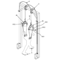
- FIG. 1 schematically illustrates an example of the weight unloading device 100 according to the present embodiment.
- the weight unloading device 100 is used to unload the weight of the user W at least partially.
- the purpose of unloading the weight of the user W (that is, the purpose of using the weight unloading device 100) may not be particularly limited, and may be appropriately determined according to the embodiment.
- the weight unloading device 100 may be used for training of gait movements of persons with gait disorders such as hemiplegic stroke patients and elderly people who have difficulty walking by themselves.
- the user W may be appropriately read as, for example, a target person, a wearer, a trainee, or the like, depending on the situation.
- the weight unloading device 100 includes a first actuator 1, a second actuator 2, a first support member 3, a second support member 4, a sensor 5, a control device 6, and a hanger FL.
- Each actuator (1, 2) supplies a load-relief force to each leg of the user W.
- Each support member (3, 4) transmits the load-relief force supplied by each actuator (1, 2) to each leg of the user W.
- the sensor 5 measures information indicating the bias of the floor reaction force acting on each leg of the user W.
- the control device 6 determines the magnitude of the unloading force for each leg based on the information indicating the bias of the floor reaction force measured by the sensor 5, and controls the operation of each actuator (1, 2).
- the hanger FL suspends each support member (3, 4) so that one end (proximal end (31, 41) described later) of each support member (3, 4) hangs from above the user W. Lower.
- the weight unloading device 100 applies each unloading force whose size is determined according to the bias of the floor reaction force to each leg of the user W, thereby at least a part of the weight of the user W. Can be lifted vertically.
- the first actuator 1 and the first support member 3 are used to give a load-relief force to the left leg of the user W (hereinafter, also simply referred to as “left leg”). It is used.
- the second actuator 2 and the second support member 4 are used to give a load-relief force to the right leg portion of the user W (hereinafter, also simply referred to as “right leg”). That is, the left leg of the user W is an example of the "one leg" of the present invention, and the right leg of the user W is an example of the "other leg” of the present invention.
- the relationship between each component and the body direction of the user W does not have to be limited to such an example. The relationship may be the opposite of this embodiment.
- first actuator 1 and the first support member 3 are used to apply an unloaded force to the right leg of the user W
- second actuator 2 and the second support member 4 are unloaded to the left leg of the user W. It may be used to give force.
- “One” may correspond to either left or right
- “the other” may correspond to either left or right
- the “first” may correspond to either the left or right
- the “second” may correspond to either the left or the right.
- the "leg” is a portion between the legs and the waist, and may be referred to as a "lower limb".
- the "foot” is the part below the ankle (the part from the sole of the foot), which is the part of the leg that touches the ground.
- the "sole” is the surface of the foot that touches the ground.
- each actuator (1, 2) is composed of a pneumatic artificial muscle.
- a valve 11 is attached to the first actuator 1 in order to control the air pressure acting on the artificial muscle.
- the second actuator 2 is composed of a pneumatic artificial muscle.
- a valve 21 is attached to the second actuator 2.
- the type of pneumatic artificial muscle of each actuator (1 and 2) does not have to be particularly limited, and may be appropriately selected according to the embodiment.
- the actuator device proposed in Japanese Patent Application Laid-Open No. 2016-61302 may be used.
- Each valve (11, 21) is connected to a common compressor CP. As a result, a common primary pressure is supplied to each valve (11, 21) from the compressor CP. Each valve (11, 21) is controlled by the control device 6 and outputs a pressure adjusted from the primary pressure to each actuator (1, 2). A known pressure control valve may be used for each valve (11, 21).
- Pneumatic artificial muscle is an example of an actuator that obtains power by injecting air into an elastic material such as rubber or carbon fiber, and is relatively inexpensive. Therefore, in the present embodiment, by using a pneumatic artificial muscle for each actuator (1, 2), the manufacturing cost of the weight unloading device 100 can be suppressed.
- the periphery of the second actuator 2 (artificial muscle) is covered with a cover, whereas the first actuator 1 (artificial muscle) is not covered and is exposed. ..
- the presence or absence of this cover does not have to be particularly limited, and may be appropriately selected depending on the embodiment.
- the cover of the second actuator 2 may be omitted.
- the periphery of the first actuator 1 may be covered with a cover.
- the first support member 3 has a proximal end 31 and a distal end 32.
- the proximal end 31 is an end close to the user W
- the distal end 32 is an end different from the proximal end 31 and away from the user W.
- the distal end 32 is connected to the first actuator 1.
- the "connection” may be direct or indirect. The same applies to the "connection” of other components.
- the linear encoder 15 is attached to the connecting portion between the distal end 32 of the first support member 3 and the first actuator 1.
- the linear encoder 15 measures the muscle contraction rate of the pneumatic artificial muscle constituting the first actuator 1.
- the proximal end 31 is attached to the user W so that the first unloading force supplied by the first actuator 1 acts on the leg on the left side of the user W.
- the second support member 4 has a proximal end 41 and a distal end 42.
- the distal end 42 is connected to the second actuator 2.
- the linear encoder 25 is attached to the connecting portion between the distal end 42 of the second support member 4 and the second actuator 2.
- the linear encoder 25 measures the muscle contraction rate of the pneumatic artificial muscle constituting the second actuator 2.
- the proximal end 41 is attached to the user W so that the second unloading force supplied by the second actuator 2 acts on the leg on the right side of the user W.
- the hanger FL suspends each support member (3, 4) so that the proximal ends (31, 41) of each support member (3, 4) hang from above the user W.
- the hanger FL includes a pair of column portions (F1, F2), a beam portion F3, and a pair of holding portions (F4, F5).
- Each pillar portion (F1, F2) is configured to extend in the vertical direction, and is arranged on each of the left and right sides of the user W.
- each pillar portion (F1, F2) may be fixed to the left and right sides of the treadmill.
- a moving component such as a caster may be attached to the lower end of each pillar (F1, F2) so that the hanger FL can track the movement of the user W.
- the beam portion F3 is bridged between the upper ends of each column portion (F1, F2) and is configured to extend in the horizontal direction.
- the beam portion F3 is provided with a pair of holding portions (F4, F5) arranged at intervals in the horizontal direction.
- the distance between the pair of holding portions (F4, F5) is preferably set to be slightly narrower than the shoulder width of the user W in order to apply the load-relieving force to the inside of the shoulder of the user W.
- Each holding portion (F4, F5) is configured to hold each supporting member (3, 4). Details of this configuration will be described later. Further, since each holding portion (F4, F5) is provided with a clamp portion (F41, F51), the position where each holding portion (F4, F5) is fixed to the beam portion F3 is adjustable. .. Thereby, the distance between the pair of holding portions (F4, F5) can be adjusted.
- the material of each component of the hanger FL does not have to be particularly limited, and may be appropriately selected according to the embodiment.
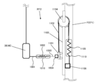
- the first support member 3 includes a cable 35, a connector 36, a first rope 37, a second rope 38, and a third rope 39.
- the cable 35 is composed of an outer cable 355 and an inner cable 356.
- the cable 35 has a proximal end 351 and a distal end 352.
- the distal end 352 of the cable 35 constitutes the distal end 32 of the first support member 3. That is, the distal end 352 of the cable 35 is connected to the first actuator 1.
- the first actuator 1 and the valve 11 are attached to the pillar portion F1 on the right side when viewed from the user W.
- the cable 35 extends from the first actuator 1 and is held by a holding portion F4 arranged on the left half body side of the user W, whereby the cable 35 is suspended on the left half body side of the user W by the hanger FL.
- a distance for crossing the cable 35 is secured, and the transmissibility of the first load-relief force in the cable 35 is secured. Can be prevented from being impaired.
- the connector 36 is formed in a dogleg shape like a boomerang.
- the connector 36 has a first end portion 361, a second end portion 362, and a convex portion 363.
- the first end portion 361 is directed to the front of the user W when using the weight unloading device 100.
- the second end 362 is directed to the rear of the user W during use.
- the convex portion 363 is arranged between both end portions (361, 362) and is directed upward.
- the first rope 37 connects the convex portion 363 of the connecting tool 36 and the proximal end 351 of the cable 35.
- a load cell 30 is attached to the joint portion of the first rope 37 and the proximal end 351 of the cable 35.
- the load cell 30 is a first unloading force supplied by the first actuator 1, and measures the first unloading force acting on the left leg of the user W.
- the length of the first rope 37 is adjustable.
- the second rope 38 has a proximal end 381 and a distal end 382.
- the distal end 382 is coupled to the first end 361 of the connector 36.
- the third rope 39 has a proximal end 391 and a distal end 392.
- the distal end 392 is coupled to the second end 362 of the connector 36.
- the proximal ends (381, 391) of the second rope 38 and the third rope 39 respectively, constitute the proximal end 31 of the first support member 3. That is, the proximal ends (381, 391) of each rope (38, 39) are attached to the user W.
- the second support member 4 is configured in the same manner as the first support member 3. That is, the second support member 4 includes a cable 45, a connector 46, a first rope 47, a second rope 48, and a third rope 49.
- the cable 45 is composed of an outer cable 455 and an inner cable 456.
- the cable 45 has a proximal end 451 and a distal end 452.
- the distal end 452 of the cable 45 constitutes the distal end 42 of the second support member 4 and is connected to the second actuator 2.
- the second actuator 2 and the valve 21 are attached to the pillar portion F2 on the left side when viewed from the user W.
- the cable 45 extends from the second actuator 2 and is held by a holding portion F5 arranged on the right half body side of the user W, whereby the cable 45 is suspended on the right half body side of the user W by the hanger FL.
- a distance for crossing the cable 45 is secured, and the transmissibility of the second load-relieving force in the cable 45 is secured. Can be prevented from being impaired. That is, in the present embodiment, the cable 35 of the first support member 3 extends from the first actuator 1 attached to the right pillar portion F1 toward the left holding portion F4, and is attached to the left pillar portion F2.
- the cables (35, 45) intersect slightly above the beam portion F3.
- the curve formed above the beam portion F3 of each cable (35, 45) can be made gentle. ..
- the loss of each unloading force in each cable (35, 45) can be reduced.
- the height of the portion of each cable (35, 45) that curves upward from the beam portion F3 can be lowered.
- the connector 46 is formed in a dogleg shape like a boomerang.
- the connector 46 has a first end portion 461, a second end portion 462, and a convex portion 463.
- the first end portion 461 is directed to the front of the user W
- the second end portion 462 is directed to the rear of the user W.
- the direction in which each end portion (461, 462) faces is not limited to such an example, and may be appropriately selected according to the embodiment.
- the convex portion 463 is arranged between both end portions (461, 462) and is directed upward.
- the first rope 47 connects the convex portion 463 of the connecting tool 46 and the proximal end 451 of the cable 45.
- a load cell 40 is attached to the joint portion of the first rope 47 and the proximal end 451 of the cable 45.
- the load cell 40 is a second unloading force supplied by the second actuator 2, and measures the second unloading force acting on the leg on the right side of the user W.
- the length of the first rope 47 is adjustable.
- the joint portion of the first rope 37 including the load cell 30 and the proximal end 351 of the cable 35 is covered with a cover, whereas the first rope 47 including the load cell 40 and The coupling portion of the proximal end 451 of the cable 45 is uncovered and exposed.
- the presence or absence of this cover does not have to be particularly limited, and may be appropriately selected depending on the embodiment.
- the cover of the joint portion of the first support member 3 may be omitted.
- the joint portion of the second support member 4 may be covered with a cover.
- the second rope 48 has a proximal end 481 and a distal end 482.
- the distal end 482 is coupled to the first end 461 of the connector 46.
- the third rope 49 has a proximal end 491 and a distal end 492.
- the distal end 492 is coupled to the second end 462 of the connector 46.
- Proximal ends (481, 491) of the second rope 48 and the third rope 49, respectively, constitute the proximal end 41 of the second support member 4. That is, the proximal ends (481, 491) of each rope (48, 49) are attached to the user W.
- FIGS. 2A and 2B are perspective views and side views schematically illustrating an example of the connecting tool (36, 46).
- the rope ascender 370 is provided on the convex portion 363 of the connecting tool 36 of the first support member 3.
- One end 371 of the first rope 37 is pulled out from the rope ascender 370.
- the other end of the first rope 37 is fixed by the fastener 373 at the convex portion 363.
- the first rope 37 forms an annular portion, and the convex portion 363 of the connector 36 and the proximal end 351 of the cable 35 are connected by the annular portion. Further, the length of the annular portion of the first rope 37 can be adjusted by operating the rope ascender 370 to change the drawn length of the one end portion 371. As a result, the first rope 37 is configured so that the length connecting the convex portion 363 of the connecting tool 36 and the proximal end 351 of the cable 35 can be adjusted. By adjusting the length of the connection, the connector 36 can be arranged at a height suitable for the height of the user W.
- the distal end 382 of the second rope 38 is fixed by a fastener 380 at the first end 361.
- the distal end 392 of the third rope 39 is secured by a fastener 390 at the second end 362.
- Known fasteners may be used for each fastener (373, 380, 390). Notches are formed at each end (361, 362) to capture each rope (38, 39). As a result, it is possible to suppress the shaking of each rope (38, 39) with respect to the connecting tool 36.
- each proximal end (381, 391) of each rope (38, 39) is attached to the user W.
- the configuration for attaching each proximal end (381, 391) to the user W does not have to be particularly limited, and may be appropriately determined according to the embodiment.
- each proximal end (381, 391) may be equipped with a rope ratchet.
- a holder for attaching the rope ratchet may be provided near the waist of the left half of the pants worn by the user W.
- the lengths of the second rope 38 and the third rope 39 can be adjusted so as to be suitable for the length of the body of the user W, and the proximal end 31 of the first support member 3 can be adjusted to the proximal end 31 of the user W. It can be attached and detached with one touch.
- the connecting tool 46 of the second support member 4 is configured in the same manner as the connecting tool 36 of the first support member 3. That is, the rope ascender is configured to allow the length of the first rope 47 of the second support member 4 to connect the convex portion 463 of the connector 46 and the proximal end 451 of the cable 45 to be adjustable. By adjusting the length of the connection, the connection tool 46 can be arranged at a height suitable for the height of the user W. Further, the distal ends (482, 492) of each rope (48, 49) are fixed by fasteners at each end (461, 462) of the connecting tool 46.
- each end (461, 462) is formed with a notch for capturing each rope (48, 49), thereby suppressing the swing of each rope (48, 49) with respect to the connector 46. it can.
- each proximal end (481, 491) of each rope (48, 49) is attached to the user W.
- the configuration for mounting each proximal end (481, 491) to the user W is not particularly limited and may be appropriately determined according to the embodiment.
- each proximal end (481, 491) may be equipped with a rope ratchet.
- a holder for attaching the rope ratchet may be provided near the waist of the right half of the pants worn by the user W.
- the lengths of the second rope 48 and the third rope 49 can be adjusted so as to be suitable for the length of the body of the user W, and the proximal end 41 of the second support member 4 is set to the user W. It can be attached and detached with one touch.
- each component of each support member (3, 4) does not have to be particularly limited, and may be appropriately selected according to the embodiment.
- a Bowden cable may be used for each cable (35, 45).
- Climbing ropes may be used for each rope (36-39, 46-49).
- Resin materials such as fiber reinforced plastics and engineering plastics may be used for each connector (36, 46). As shown in FIG. 1, each connector (36, 46) may be covered so that the internal structure is not exposed.
- FIG. 2C is a cross-sectional view schematically illustrating an example in which each cable (35, 45) is held by each holding portion (F4, F5) according to the present embodiment.
- each cable (35, 45) includes an outer cable (355, 455) and an inner cable (356, 456).
- Each holding portion includes a flat plate portion 80 having a through hole 81 penetrating in the vertical direction.
- the through hole 81 includes a first portion 811, a second portion 812, and a third portion 813 in this order from above in the vertical direction.
- the diameter of the first portion 811 is the largest, and the diameter of the third portion 813 is the smallest.
- a bolt 82 supported by the pillow ball 83 is inserted into the through hole 81.
- the bolt 82 has a shape extending in one direction (axial direction), and includes a head portion 821 and a shaft portion 822 arranged along the one direction.
- the diameter of the head portion 821 is larger than the diameter of the shaft portion 822, and the pillow ball 83 is locked to the head portion 821 and supports the shaft portion 822.
- the pillow balls 83 are arranged in the first portion 811 and the second portion 812 of the through hole 81, and the shaft portion 822 of the bolt 82 extends outward through the third portion 813 of the through hole 81. As a result, the bolt 82 is inserted into the through hole 81 via the pillow ball 83.
- the bolt 82 is provided with a through hole 824 penetrating the head portion 821 and the shaft portion 822 along one direction in the center of the plane.
- Each cable (35, 45) is held by each holding portion (F4, F5) by being inserted into the through hole 824 of the bolt 82.
- the through hole 824 includes a first portion 825 and a second portion 826 in order from the head 821 side. The diameter of the first portion 825 is larger than the diameter of the second portion 826.
- each outer cable (355, 455) of each cable (35, 45) is inserted into the first portion 825. That is, each outer cable (355, 455) extends from each actuator (1, 2) to the bolt 82 of each holding portion (F4, F5).
- the length of the inner cable (356, 456) of each cable (35, 45) is longer than that of the outer cable (355, 455).
- the inner cables (356, 456) of each cable (35, 45) extend outward via the second portion 826 of the through hole 824.
- the distal end of the inner cable (356, 456) is connected to each actuator (1, 2), and the proximal end is connected to the first rope (37, 47).
- Each unloading force supplied by each actuator (1, 2) is transmitted to the first rope (37, 47) via each inner cable (356, 456).
- each cable (35, 45) By holding each cable (35, 45) in each holding portion (F4, F5) with the above configuration, the following effects can be obtained. That is, when each cable (35, 45) moves back and forth and left and right and tilts from the vertical direction while the user W is walking, the pillow ball 83 rotates and slides in the feeding direction of the cable (35, 45). Therefore, it is possible to suppress the occurrence of friction of the cables (35, 45) in each holding portion (F4, F5). As a result, it is possible to suppress the loss of each unloading force transmitted from each actuator (1, 2). Further, it is possible to prevent each cable (35, 45) from being cut due to friction.
- each holding portion (F4, F5) is provided with a bearing such as a pillow ball, and by holding each cable (35, 45) via the bearing, a degree of freedom may be provided in the feeding direction of the cable (35, 45).
- the degree of freedom in the feeding direction of the cables (35, 45) is realized by the action of bearings such as rotation and sliding. Thereby, similarly to the above, it is possible to suppress the occurrence of friction of the cables (35, 45) in each holding portion (F4, F5).
- each of the holding portions (F4, F5) is also incorporated into the connecting portion between the distal end of the outer cable (355, 455) of each support member (3, 4) and each actuator (1, 2). May be done. As a result, it is possible to allow a mounting error between the drive shaft of each actuator (1, 2) and each support member (3, 4).
- FIG. 3 schematically illustrates an example of the sensor 5 according to the present embodiment.
- the sensor 5 is configured to measure information indicating the bias of the floor reaction force acting on each leg of the user W.
- the sensor 5 is composed of the first sensor 51 and the second sensor 52.
- the first sensor 51 is arranged on the heel side (for example, the heel portion) of the sole, the first force sensor 511, and the second sensor 51 is arranged on the toe side (for example, the toe portion) of the sole.
- the first sensor 51 may be arranged, for example, on the insole of the shoe worn by the user W on the left leg.
- the first sensor 51 according to the present embodiment is configured to measure the first floor reaction force acting on the sole of the left leg of the user W.
- the second sensor 52 includes a first force sensor 521 arranged on the heel side of the sole and a second force sensor 522 arranged on the toe portion of the sole.
- the second sensor 52 may be arranged, for example, on the insole of the shoe worn on the right leg of the user W.
- the second sensor 52 according to the present embodiment is configured to measure the second floor reaction force acting on the sole of the leg on the right side of the user W.
- a load cell may be used for each force sensor (511, 512, 521, 522).
- each first force sensor (511, 521) is arranged on the heel portion
- each second force sensor (512, 522) is arranged on the toe portion, so that each leg portion is arranged during the walking period. It is possible to accurately measure the floor reaction force acting on the sole of the foot. Thereby, the bias of the floor reaction force measured accurately can be reflected in the determination of the unloading force for each leg. Further, as described above, relatively inexpensive sensors such as a load cell and a Force Sensing Resister (FSR) can be used for each sensor (51, 52). Therefore, the manufacturing cost of the weight unloading device 100 can be suppressed.
- FSR Force Sensing Resister
- FIG. 4 schematically illustrates an example of the system configuration of the weight unloading device 100 including the control device 6.
- the control device 6 is a computer configured to control the operation of each actuator (1, 2).
- the bias of the floor reaction force acting on each leg of the user W is measured by the sensor 5.
- the control device 6 acquires information indicating the bias of the floor reaction force measured by the sensor 5.
- the control device 6 determines the magnitudes of the first unloading force and the second unloading force according to the bias of the floor reaction force indicated by the acquired information. Then, the control device 6 controls each of the first actuator 1 and the second actuator 2 so as to generate the first unloading force and the second unloading force of the determined sizes, respectively.
- each actuator (1, 2) is composed of a pneumatic artificial muscle.
- Each valve (11, 21) is attached to each actuator (1, 2), and each valve (11, 21) is connected to a compressor CP.
- a common primary pressure is supplied to each valve (11, 21) from the compressor CP.
- the control device 6 controls the output valve of each valve (11, 21) to adjust the pressure of the compressed air output from each valve (11, 21).
- the control device 6 controls the operation of the first actuator 1 so that the first unloading force of the determined magnitude is output from the first actuator 1.
- the control device 6 controls the operation of the second actuator 2 so that the second unloading force of a determined size is output from the second actuator 2.
- the first unloading force output from the first actuator 1 is applied to the left leg of the user W
- the second unloading force output from the second actuator 2 is the right side of the user W. Given to the legs of.
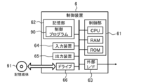
- FIG. 5 schematically illustrates an example of the hardware configuration of the control device 6 according to the present embodiment.
- the control device 6 is a computer to which the control unit 61, the storage unit 62, the external interface 63, the input device 64, the output device 65, and the drive 66 are electrically connected. ..
- the external interface is described as "external I / F".
- the control unit 61 includes a CPU (Central Processing Unit), a RAM (Random Access Memory), a ROM (Read Only Memory), and the like, which are examples of processors, and is configured to execute information processing based on a program and various data.
- the storage unit 62 is an example of a memory, and is composed of, for example, a hard disk drive, a solid state drive, or the like. In the present embodiment, the storage unit 62 stores various information such as the control program 90.
- the control program 90 is a program for causing the control device 6 to execute information processing (FIG. 9) described later regarding the control of each actuator (1, 2).
- the control program 90 includes a series of instructions for the information processing. Details will be described later.
- the external interface 63 is, for example, a USB (Universal Serial Bus) port, a dedicated port, or the like, and is an interface for connecting to an external device.
- the type and number of the external interfaces 63 may be appropriately selected according to the type and number of connected external devices.
- the external interface 63 and the external device may be connected by wire or wirelessly.
- control device 6 is connected to each valve (11, 21) of each actuator (1, 2) via the external interface 63, and the driving force (1, 2) output from each actuator (1, 2) is output. Unloading capacity) is controlled. Further, the control device 6 is connected to the sensor 5, each linear encoder (15, 25), and each load cell (30, 40) via the external interface 63, and information indicating the bias of the floor reaction force, each artificial muscle. Various information such as information indicating the muscle contraction rate of the muscle contraction rate and the measured value of each unloading force is acquired.
- the input device 64 is, for example, a device for inputting a mouse, a keyboard, or the like.
- the output device 65 is, for example, a device for outputting a display, a speaker, or the like.
- the operator can operate the control device 6 by using the input device 64 and the output device 65.
- the operator is, for example, the user W himself, an assistant who assists the training of the user W, and the like.
- the drive 66 is, for example, a CD drive, a DVD drive, or the like, and is a drive device for reading a program stored in the storage medium 91.
- the type of the drive 66 may be appropriately selected according to the type of the storage medium 91.
- the control program 90 may be stored in the storage medium 91.
- the storage medium 91 stores the information of the program or the like by electrical, magnetic, optical, mechanical or chemical action so that the information of the program or the like recorded by the computer or other device or machine can be read. It is a medium to do.
- the control device 6 may acquire the control program 90 from the storage medium 91.
- FIG. 5 illustrates a disc-type storage medium such as a CD or DVD as an example of the storage medium 91.
- the type of the storage medium 91 is not limited to the disc type, and may be other than the disc type.
- Examples of storage media other than the disk type include semiconductor memories such as flash memories.
- the control unit 61 may include a plurality of processors.
- the processor may be composed of a microprocessor, an FPGA (field-programmable gate array), a DSP (digital signal processor), or the like.
- the storage unit 62 may be composed of a RAM and a ROM included in the control unit 61. At least one of the external interface 63, the input device 64, the output device 65, and the drive 66 may be omitted.
- the control device 6 may be composed of a plurality of computers. In this case, the hardware configurations of the computers may or may not match. Further, the control device 6 may be a general-purpose PC (Personal Computer) or the like, in addition to an information processing device designed exclusively for the provided service.
- PC Personal Computer
- FIG. 6 schematically illustrates an example of the software configuration of the control device 6 according to the present embodiment.
- the control unit 61 of the control device 6 expands the control program 90 stored in the storage unit 62 into the RAM. Then, the control unit 61 interprets the instructions included in the control program 90 expanded in the RAM by the CPU, controls each component, and executes information processing corresponding to the instructions.
- the control device 6 includes software for the information acquisition unit 611, the load unloading force determination unit 612, the unloading command unit 613, the designated reception unit 614, and the initial setting unit 615. Operates as a computer equipped as a module. That is, in the present embodiment, each software module of the control device 6 is realized by the control unit 61 (CPU).
- the information acquisition unit 611 acquires information indicating the bias of the floor reaction force measured by the sensor 5. In the present embodiment, the information acquisition unit 611 further acquires information indicating the muscle contraction rate of the artificial muscles constituting the actuators (1, 2) measured by the linear encoders (15, 25). In addition, the information acquisition unit 611 acquires information indicating the actually measured values of the load-unloading forces supplied by the actuators (1, 2) measured by the load cells (30, 40).
- the unloading force determination unit 612 determines the magnitudes of the first unloading force and the second unloading force according to the bias of the floor reaction force indicated by the acquired information.
- the unloading command unit 613 controls each of the first actuator 1 and the second actuator 2 so as to generate the first unloading force and the second unloading force of the determined sizes, respectively.
- the bias of the floor reaction force is the first ratio of the floor reaction force acting on the left leg to the total floor reaction force acting on both legs, and the total floor reaction force acting on both legs. It is expressed by the second ratio of the floor reaction force acting on the right leg with respect to. Determining the size of each of the first and second unloading powers depends on the first ratio and the size of the second unloading power, and according to the second ratio. It includes determining the magnitude of the first load-relief capacity.
- the sensor 5 is composed of the first sensor 51 and the second sensor 52. Therefore, to acquire the information indicating the bias of the floor reaction force, the value of the first floor reaction force measured by the first sensor 51 and the value of the second floor reaction force measured by the second sensor 52 are acquired. Including to do.
- the first ratio is the ratio of the value of the first floor reaction force to the total value of the first floor reaction force and the second floor reaction force
- the second ratio is the ratio of the first floor reaction force and the second floor reaction force. It is the ratio of the value of the second floor reaction force to the total value of.
- the measured value of the first floor reaction force is the total value of the floor reaction force measured by the first force sensor 511 and the second force sensor 512.
- the measured value of the second floor reaction force is the total value of the floor reaction force measured by the first force sensor 521 and the second force sensor 522.
- each ratio and each unloading capacity may be appropriately determined according to the embodiment.
- determining the magnitude of the second unloading capacity according to the first ratio means increasing the second unloading capacity as the first ratio increases, and the first. This includes reducing the second unloading capacity as the ratio decreases.
- determining the magnitude of the first unloading capacity according to the second ratio means increasing the first unloading capacity as the second ratio increases, and the second ratio It includes reducing the first unloading capacity as it becomes smaller.
- the method of realizing the relationship between each ratio and each unloading capacity may be appropriately determined according to the embodiment.
- the relationship between each ratio and each unloading capacity may be defined, for example, by a given function.
- determining the magnitude of the second unloading force according to the first ratio is calculated by calculating the first product of the first ratio and the first proportionality constant. It is composed of calculating the first sum of the first product and the first constant term, and adopting the calculated first sum as the value of the second unloading capacity.
- determining the magnitude of the first unloading force according to the second ratio is to calculate the second product of the second ratio and the second proportionality constant, the calculated second It is composed of calculating the second sum of the product of and the second constant term, and adopting the calculated second sum as the value of the first unloading capacity. That is, in the present embodiment, the relationship between each ratio and each unloading force is expressed by a linear function. Each constant term defines each unloading force bias.
- FIG. 7 shows an example of the process of calculating each unloading force and controlling each actuator (1, 2).
- FIG. 8 shows an example of the relationship between the bias of the floor reaction force and each unloading force.
- the information acquisition unit 611 acquires the value of each floor reaction force measured by each sensor (51, 52) constituting the sensor 5 as information indicating the bias of the floor reaction force. ..
- the floor reaction force value F FP is expressed by the following equation 1.
- FLH indicates the measured value obtained by the first force sensor 511 of the first sensor 51
- FLT indicates the measured value obtained by the second force sensor 512. That is, the total value of FLH and FLT is an example of the value of the first floor reaction force.
- F RH indicates a measured value obtained by the first force sensor 521 of the second sensor 52
- F RT indicates a measured value obtained by the second force sensor 522. That is, the total value of F RH and F RT is an example of the value of the second floor reaction force.
- the information acquisition unit 611 calculates the first ratio and the second ratio by the calculation of the following equations 2 and 3.
- the first ratio is represented by the ratio of the value of the first floor reaction force to the total value of the first floor reaction force and the second floor reaction force.
- the second ratio is represented by the ratio of the value of the second floor reaction force to the total value of the first floor reaction force and the second floor reaction force.
- the unloading force determination unit 612 determines the magnitude of each unloading force (target value 70) according to each obtained ratio. Specifically, according to the following equation 4, the unloading force determination unit 612 determines the magnitude of the second unloading force according to the first ratio, and the first according to the second ratio. Determine the size of the unloading capacity.
- F FP Fref
- F ref indicates the calculated target value 70.
- FLref indicates the magnitude of the determined first load relief capacity.
- F Rref indicates the magnitude of the determined second load relief capacity.
- ⁇ R is an example of the first proportionality constant, and ⁇ R is an example of the first constant term.
- ⁇ L is an example of the second proportionality constant, and ⁇ L is an example of the second constant term.
- the first proportionality constant is set to a positive value.
- the second unloading capacity increases as the first ratio increases, and the second unloading capacity decreases as the first ratio decreases.
- the magnitude of the load-relief capacity can be determined.
- the second proportionality constant is set to a positive value.
- the magnitude of the first unloading capacity is increased so that the first unloading capacity increases as the second ratio increases and the first unloading capacity decreases as the second ratio decreases.
- Each constant term ( ⁇ R , ⁇ L ) defines the bias of each unloading force.
- the horizontal axis of the graph shown in FIG. 8 indicates the second ratio.
- the total value of the first unloading force and the second unloading force is fixed to a fixed predetermined value. In this way, the total value of the first unloading capacity and the second unloading capacity may be maintained at a constant predetermined value.
- the setting of the load relief capacity does not have to be limited to such an example.
- the total value of the first unloading capacity and the second unloading capacity does not have to be fixed at a fixed predetermined value.
- the information acquisition unit 611 muscle contraction of the artificial muscles constituting the actuators (1, 2) measured by the linear encoders (15, 25). Get information that shows the rate.
- the muscle contraction rate ⁇ of each artificial muscle is expressed by the following equation 5.
- ⁇ L indicates the muscle contraction rate of the first actuator 1 measured by the linear encoder 15.
- ⁇ R indicates the muscle contraction rate of the second actuator 2 measured by the linear encoder 25.
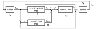
- the driving force (unloading force) output by each actuator (1 and 2) is determined according to the muscle contraction rate of the artificial muscle and the pressure of the air to be applied. Therefore, the unloading command unit 613 applies the pressure P f to each actuator (1, 2) by the following equations 6 to 8 in order to realize the output of the desired unloading force F ref by the feedforward control 71. To determine.
- f PAM (F ref , ⁇ ) is a function for calculating the pressure P f applied to each actuator (1, 2) from the target value 70 (F ref ) of the unloading force and the muscle contraction rate ⁇ of each artificial muscle.
- P u indicates a reference pressure on the high pressure side (hereinafter, also referred to as “high pressure side reference pressure”).
- P l indicates a reference pressure on the low pressure side (hereinafter, also referred to as “low pressure side reference pressure”).
- the high-pressure side reference pressure and the low-pressure side reference pressure indicate the air pressure used for calibrating the artificial muscle.
- f l is a proportional constant indicating the relationship between the force of the pneumatic artificial muscle and the air pressure at the high-pressure side reference pressure P u .
- fu u is a proportional constant indicating the relationship between the force of the pneumatic artificial muscle and the air pressure at the low pressure side reference pressure Pl .
- This proportionality constant is approximated by a quadratic equation at each reference pressure P u and P l .
- (A u, b u, c u), and (a l, b l, c l) is a coefficient of a quadratic equation in the approximation.
- PLf indicates the pressure of air applied to the first actuator 1.
- PRf indicates the pressure of air applied to the second actuator 2.
- the model formula by approximation of the pneumatic artificial muscle is given by a quadratic function.
- the model expression may be approximated by using a higher-order function expression, for example, a polynomial of degree 3 or higher, a trigonometric function, or the like.
- the information acquisition unit 611 is a leg portion of the user W measured by each load cell (30, 40). Obtain information indicating the measured value of the load-relief capacity for.
- the measured value F PAM of each unloading force is expressed by the following equation 9.
- FLPAM indicates an actually measured value of the first unloading force measured by the load cell 30.
- F RPAM indicates an actually measured value of the second unloading force measured by the load cell 40.
- the method of the feedback control 72 does not have to be particularly limited, and may be appropriately selected depending on the embodiment. For the feedback control 72, known methods such as PI control and PID control may be adopted.
- the unloading command unit 613 calculates the deviation e between the target value 70 (F ref ) and the measured value (F PAM ) of each unloading force by the following equation 10. Then, the unloading command unit 613 calculates the correction amount P PID of the pressure applied to each actuator (1, 2) based on the calculated deviation e by the following equation 11.
- e L indicates the deviation between the target value 70 of the first unloading force and the measured value.
- e R indicates the deviation between the target value 70 of the second unloading capacity and the measured value.
- P LPID indicates a correction amount of pressure applied to the first actuator 1.
- P RPID indicates the amount of pressure correction applied to the second actuator 2.
- K p is the proportional gain
- K d is the differential gain
- Ti is the integrated gain.
- Each gain may be adjusted experimentally. The adjustment of each gain may be performed by, for example, a step response method, a limit sensitivity method, or the like.
- the unloading command unit 613 adds the pressure correction amount P PID determined by the feedback control 72 to the pressure value P f determined by the feedforward control 71 according to the following equation 12 to each actuator (1).
- the value P of the pressure applied to 2) is determined.
- P L indicates the pressure applied to the first actuator 1.
- P R represents the pressure applied to the second actuator 2.
- the unloading command unit 613 adjusts the pressure of air output from the compressor CP to each actuator (1, 2) via each valve (11, 21) by giving a command to each valve (11, 21). To do. As a result, the unloading command unit 613 applies the determined pressure P to each actuator (1, 2) so that the desired unloading force is output from each actuator (1, 2). 1 and 2) are controlled.
- the designated reception unit 614 accepts the designation of the value of the parameter for determining the unloading force such as each constant term of the equation 4.
- the initial setting unit 615 applies compressed air of a predetermined pressure to each actuator (1, 2) after the proximal ends (31, 41) of each support member (3, 4) are attached to the user W. Control each valve (11, 21). Then, the initial setting unit 615 via the output device 65 so as to tension each support member (3, 4) so that the muscle contraction rate measured by each linear encoder (15, 25) becomes a predetermined value. Outputs instructions to the operator. As a result, the initial setting unit 615 performs the initial setting of the artificial muscles constituting each actuator (1, 2).
- each software module of the control device 6 will be described in detail in an operation example described later.
- an example in which each software module of the control device 6 is realized by a general-purpose CPU is described.
- some or all of the above software modules may be implemented by one or more dedicated processors.
- the software module may be omitted, replaced, or added as appropriate according to the embodiment.
- FIG. 9 is a flowchart showing an example of a processing procedure related to weight unloading of the control device 6 according to the present embodiment.
- the processing procedure described below is an example of a control method. However, the processing procedure described below is only an example, and each processing may be changed as much as possible. Further, with respect to the processing procedure described below, steps can be omitted, replaced, and added as appropriate according to the embodiment.
- the user W moves under the beam portion F3 of the hanger FL, and attaches the proximal ends (31, 41) of each support member (3, 4) to the vicinity of the waist.
- the proximal ends (381, 391) of each rope (38, 39) of the first support member 3 may include a low ratchet.
- the user W may attach the rope ratchets at the proximal ends (381, 391) to the holders provided near the waist of the left half of the body.
- the proximal ends (481, 491) of each rope (48, 49) of the second support member 4 may be provided with a low ratchet.
- the user W may attach the rope ratchets at the proximal ends (481, 491) to the holders provided near the waist of the right half of the body. As a result, the user W can attach the proximal ends (31, 41) of each support member (3, 4) to the vicinity of the waist. This attachment may be assisted by an assistant.
- the control device 6 may recognize that the proximal ends (31, 41) of each support member (3, 4) are attached to the user W by, for example, an operation via the input device 64 of the operator. .. In response to this, the control device 6 may execute the following information processing.
- Step S10 the control unit 61 operates as the initial setting unit 615 and outputs an instruction for performing the initial setting of each actuator (1, 2) to the output device 65.
- the control unit 61 applies compressed air of a predetermined pressure to each actuator (1, 2) after the proximal ends (31, 41) of each support member (3, 4) are attached to the user W. Control each valve (11, 21) to give. Then, the control unit 61 gives an instruction to the output device 65 to urge each support member (3, 4) to be tense so that the muscle contraction rate measured by each linear encoder (15, 25) becomes a predetermined value. Output.
- the driving force of the pneumatic artificial muscle is determined by the air pressure acting on the artificial muscle and the muscle contraction rate of the artificial muscle.
- the acting air pressure is small, the change in the driving force due to the fluctuation of the muscle contraction rate becomes small, and when the acting air pressure is large, the change in the driving force due to the fluctuation in the muscle contraction rate becomes large.
- the muscle contraction rate is large, the change in the driving force due to the fluctuation of the air pressure is small, and when the muscle contraction rate is small, the change in the driving force due to the fluctuation in the air pressure is large. Therefore, it is desirable to control the driving force that the air pressure and the muscle contraction rate are in an appropriate state.
- the state of the artificial muscle of each actuator (1, 2) can be initialized so as to be suitable for controlling each unloading force.
- the pressure applied to each actuator (1, 2) and the predetermined values of the muscle contraction rate may be appropriately set according to the embodiment.
- Each predetermined value may be given by a set value in the control program 90, or may be given by an input via the operator's input device 64.
- the control unit 61 recognizes the completion of the initial setting of each artificial muscle based on the measured value of the muscle contraction rate obtained from each linear encoder (15, 25) becoming a predetermined value. When the initial setting of each artificial muscle is completed, the control unit 61 proceeds to the next step S12.
- Step S12 the control unit 61 operates as the designated reception unit 614, and receives the designation of the value of the parameter of the unloading amount including each constant term ( ⁇ R , ⁇ L ) of the equation 4.
- the operator inputs the value of each parameter by the input device 64.
- the total value of the first unloading power and the second unloading power may be maintained at a constant predetermined value.
- the control unit 61 may accept the designation of each constant term ( ⁇ R , ⁇ L ) and the value of each of the total values as the parameter of the unloading amount.
- the target value 70 of each unloading capacity is calculated by the calculation of the above formula 4. Therefore, when the total value of the first unloading power and the second unloading power is maintained at a constant predetermined value, each proportionality constant ( ⁇ R , ⁇ L ) has the same value “(total value) ⁇ ( Specified as " ⁇ R + ⁇ L )". In this case, the magnitude of the unloading force for each leg can be easily adjusted by changing the value of each constant term ( ⁇ R , ⁇ L ).
- each proportional constant ( ⁇ R , ⁇ L ) becomes negative.
- the control unit 61 may return an error and accept the specification of the value of each parameter again.
- the control unit 61 may accept the designation of the value of the constant term ( ⁇ R , ⁇ L ) having a sum larger than the total value of the first unloading force and the second unloading force. Further, the total value of the first unloading capacity and the second unloading capacity may not be maintained at a constant predetermined value. In this case, the control unit 61 may further accept the designation of the value of each proportionality constant ( ⁇ R , ⁇ L ) as the parameter of the unloaded amount.
- the walking cycle I was able to improve the left-right balance. Therefore, in order to improve the left-right balance of the walking cycle, it is preferable to set the constant term on the healthy side to a larger value than the constant term on the paralyzed side.
- step S14 the control unit 61 operates as the information acquisition unit 611 to acquire information indicating the bias of the floor reaction force measured by the sensor 5.
- the sensor 5 is composed of the first sensor 51 and the second sensor 52. Therefore, the control unit 61 shows the value of the first floor reaction force measured by the first sensor 51 and the value of the second floor reaction force measured by the second sensor 52 as information indicating the bias of the floor reaction force. Get information.
- each sensor (51, 52) is composed of a first force sensor (511, 521) and a second force sensor (512, 522).
- Control unit 61 acquires information indicating the value F FP of measured floor reaction force by the force sensor (511,512,521,522). Then, the control unit 61 calculates the first ratio RL (F FP ) and the second ratio RR (F FP ) according to the above equations 2 and 3. As a result, the control unit 61 acquires information indicating the first ratio RL (F FP ) and the second ratio RR (F FP ) as information indicating the bias of the floor reaction force.
- control unit 61 acquires information indicating the muscle contraction rate ⁇ of the artificial muscle constituting each actuator (1, 2) measured by each linear encoder (15, 25) for the feedforward control 71. .. Specifically, each linear encoder (15, 25) can measure the length of the artificial muscle constituting each actuator (1, 2). The control unit 61 can derive the muscle contraction rate of each artificial muscle from this measured value. For example, the control unit 61 can derive the muscle contraction rate ⁇ by the following equation 13.
- L 0 indicates the natural length of each artificial muscle and is given in advance according to the specifications of each artificial muscle.
- L indicates the length of each artificial muscle measured by each linear encoder (15, 25).
- the control unit 61 calculates the muscle contraction rate ⁇ by substituting the measured value of the length of each artificial muscle obtained by each linear encoder (15, 25) into the equation 13 and executing the calculation of the equation 13. can do.
- control unit 61 acquires information indicating the measured value F PAM of each unloading force supplied by each actuator (1, 2) measured by each load cell (30, 40). To do.
- the route for acquiring each information does not have to be particularly limited, and may be appropriately selected according to the embodiment.
- the sensor 5, each linear encoder (15, 25), and each load cell (30, 40) may be directly connected to the control device 6 via the external interface 63.
- the control unit 61 may acquire each information directly from the sensor 5, each linear encoder (15, 25), and each load cell (30, 40) via the external interface 63.
- the sensor 5, each linear encoder (15, 25), and each load cell (30, 40) may be connected to another computer.
- the control unit 61 may indirectly acquire each information from the sensor 5, each linear encoder (15, 25), and each load cell (30, 40) via another computer. When each information is acquired, the control unit 61 proceeds to the next step S16.
- step S16 the control unit 61 operates as the load-relief force determination unit 612, and the first load-relief force ( FLref ) and the second load- relief force are obtained according to the bias of the floor reaction force indicated by the acquired information.
- F Rref Determine the size of each.
- the control unit 61 substitutes the values of the constant terms ( ⁇ R , ⁇ L ) specified in step S12 and the specified or specified proportional constants ( ⁇ R , ⁇ L ) into Equation 4. .. Further, the control unit 61 substitutes the value of each ratio ( RL (F FP ), RR (F FP )) acquired in step S14 into the equation 4. Then, the control unit 61 calculates the target value 70 of each unloading force F ref by executing the calculation of the equation 4, in other words, determines the magnitude of each unloading force F ref . After determining the size of each unloading force F ref , the control unit 61 proceeds to the next step S18.
- the control unit 61 may determine the magnitude of each unloading force F ref according to the equation 4 using each of the proportionality constants ( ⁇ R , ⁇ L ) which is a negative value.
- the proportional constant ( ⁇ R, ⁇ L) of the absolute value of the constant term ( ⁇ R, ⁇ L) is greater than the one of the absolute value either identified, the constant term ( ⁇ R, ⁇ L) of There is a possibility that the load-relief capacity exceeding the sum will be supplied to the user W.
- the control unit 61 controls the values of the specified constant terms ( ⁇ R , ⁇ L ).
- the magnitude of each unloading force F ref may be determined according to the ratio of.
- each constant term ( ⁇ R , ⁇ L ), that is, the total bias of each unloading force is set to exceed a predetermined value, the total unloading force supplied to each leg becomes. It is possible to prevent the load-relief force exceeding a desired magnitude from acting on the user W by preventing the load from exceeding a certain predetermined value.
- Each constant terms ( ⁇ R, ⁇ L) according to a ratio of, by determining the size of each relieving force F ref, in accordance with the intention of setting the constant term ( ⁇ R, ⁇ L) The unloading force can be applied to each leg of the user W.
- Step S18 the control unit 61 operates as the unloading command unit 613 to generate the first unloading force ( FLref ) and the second unloading force (F Rref ) of the determined sizes, respectively.
- Each of the first actuator 1 and the second actuator 2 is controlled.
- control unit 61 applies the pressure P f to each actuator (1, 2) according to the above equations 6 to 8 in order to realize the output of the desired unloading force F ref by the feedforward control 71.
- the feedforward control 71 information indicating the value of each unloading force F ref determined in step S16 and the muscle contraction rate ⁇ of each artificial muscle obtained in step S14 is used.
- control unit 61 uses the feedback control 72 to control each actuator (F ref ) based on the deviation e between the target value 70 (F ref ) and the measured value (F PAM ) of each unloading force according to the above equations 10 and 11. Calculate the correction amount P PID of the pressure applied to 1 and 2).
- the feedback control 72 information indicating the value of each unloading force F ref determined in step S16 and the measured value F PAM of each unloading force obtained in step S14 is used.
- the control unit 61 adds the pressure correction amount P PID determined by the feedback control 72 to the pressure value P f determined by the feedforward control 71 according to the equation 12, so that each actuator (1, 2) ) Is determined by the value P of the pressure applied to.
- the control unit 61 adjusts the pressure of air output from the compressor CP to each actuator (1, 2) via each valve (11, 21).
- the control unit 61 controls the operation of each actuator (1, 2) so that a desired driving force (unloading force) is output from each actuator (1, 2).
- the control unit 61 proceeds to the next step 20.
- Step S20 the control unit 61 determines whether or not to end the control of the operation of each actuator (1, 2).
- the end trigger may be appropriately set according to the embodiment.
- control unit 61 may accept the end designation via the input device 64. In this case, the control unit 61 determines that the control of each actuator (1, 2) is not terminated while the termination designation is not input via the input device 64. On the other hand, when the end designation is input via the input device 64, the control unit 61 determines that the control of each actuator (1, 2) is terminated.
- a time for continuing the control of each actuator (1, 2) may be set.
- the control unit 61 determines that the control of each actuator (1, 2) is not terminated until the duration elapses.
- the control unit 61 determines that the control of each actuator (1, 2) is finished.
- the duration may be specified by input via the operator's input device 64, or may be given by a set value in the control program 90.
- the duration may be set in step S12, or may be set separately from step S12.
- the control unit 61 may include a timer (not shown) in order to measure the elapsed time after controlling the operation of each actuator (1, 2).
- control unit 61 repeats the process from step S14. On the other hand, when it is determined that the control is finished, the control unit 61 ends a series of processes related to this operation example.
- the actuators (first actuator 1 and second actuator 2) that supply the load-relieving force acting on each leg of the user W are separately prepared.
- the bias of the floor reaction force required for each leg of the user W is measured by the sensor 5.
- the control device 6 determines the magnitude of each unloading force according to the bias of the floor reaction force measured by the processes of steps S14 to S18, and determines each unloading force of the determined magnitude.
- the operation of each actuator (1, 2) is controlled so as to generate it. That is, by using the bias of the floor reaction force during the walking period as a use, for example, as shown in FIG. 8, the load-relief force for each leg of the user W can be individually and dynamically adjusted. .. Therefore, according to the weight unloading device 100 according to the present embodiment, the unloading force for each of the left and right legs of the user W can be changed independently and dynamically during the walking period.
- step S16 the control device 6, in accordance with the first ratio of the floor reaction force acting on the left leg (R L (F FP)) , second Men'niryoku for right leg Determine the size of (F Rref ).
- the control device 6 determines the magnitude of the first unloading force ( FLref ) with respect to the left leg according to the second ratio ( RR (F FP )) of the floor reaction force acting on the right leg. Thereby, the magnitude of the load-relief force applied to the swing leg can be determined according to the floor reaction force against the support leg.
- each proportionality constant ( ⁇ R , ⁇ L ) is set to a positive value, the second unloading capacity is increased or decreased according to the increase or decrease of the first ratio ( RL (F FP )).
- (F Rref ) can be increased or decreased.
- the load-relieving force can be generated so as to relatively strongly support the movement of raising the legs among the walking movements.
- a hemiplegic stroke patient uses the weight unloading device 100 according to the present embodiment.
- the weight transfer can be promoted from the healthy side to the paralyzed side by controlling the load-relief force described above.
- the ratio of the support time of the leg on the paralyzed side can be increased, and the balance of the left and right support times can be improved.
- the ratio (R L (F FP), R R (F FP)) and the relieving force (F Rref, F Lref) the relationship between the proportional constant (alpha R, alpha It is given by a linear function defined by L ) and constant terms ( ⁇ R , ⁇ L ). Therefore, the magnitude of the unloading force supplied to each leg of the user W can be easily adjusted by the proportionality constant ( ⁇ R , ⁇ L ) and the constant term ( ⁇ R , ⁇ L ).
- a training program can be created according to various states of the user W.
- each support member (3, 4) the body of the user W is lifted from the front and back by the second rope (38, 48) and the third rope (39, 49).
- the second rope (38, 48) and the third rope (39, 49) are the first end (361) of the connector (36, 46) with the convex portion (363, 463) further directed upward. , 461) and the second end (362, 462).
- each support member (3, 4) is arranged inside the shoulder of the user W, and is arranged from the inside of the shoulder. The body of the user W can be lifted. As a result, each of the support members (3, 4) can stably support the body of the user W. Further, since each of the connecting tools (36, 46) is formed in a dogleg shape and arranged so as to be convex upward, the space around the shoulder of the user W can be secured. As a result, the user W can easily move his shoulders and swing his arms during walking. That is, it is possible to easily encourage the user W to perform a natural walking motion.
- each actuator (1, 2) does not have to be limited to the pneumatic artificial muscle.
- the type of each actuator (1, 2) is not particularly limited as long as it can supply the load-relieving force, and may be appropriately selected according to the embodiment.
- a pneumatic cylinder, a wire winding type motor, a series elastic actuator (Series Elastic Actuator), a hydraulic piston, a ball screw, a linear motion motor and the like may be used for each actuator (1, 2).
- a pneumatic cylinder, a wire winding type motor, a series elastic actuator (Series Elastic Actuator), a hydraulic piston, a ball screw, a linear motion motor and the like may be used.
- Different types of actuators may be used for the first actuator 1 and the second actuator 2.
- each actuator (1, 2) may be composed of one or a plurality of actuators.
- one of the output portions may be used as the first actuator 1 and the other output portion may be used as the second actuator 2.
- a pneumatic cylinder that reciprocates can take out outputs from two directions. In this case, the reciprocating motion may be made to correspond to the bias of the floor reaction force, and the output in each direction may be taken out as the output of the first actuator 1 and the second actuator 2, respectively.
- each valve (11, 21) and the compressor CP are used as a configuration for controlling the air pressure supplied to the artificial muscle of each actuator (1, 2).
- the configuration for controlling the air pressure supplied to the artificial muscle does not have to be limited to such an example, and may be appropriately determined according to the embodiment.
- a separate compressor may be prepared for each actuator (1, 2).
- the hanger FL includes a pair of column portions (F1, F2), a beam portion F3, and a pair of holding portions (F4, F5).
- the configuration of the hanger FL is not limited to such an example as long as each support member (3, 4) can be hung, and may be appropriately determined according to the embodiment.
- the suspender FL may be omitted.
- the distance between the pair of holding portions (F4, F5) may be wider than the shoulder width of the user W.
- each of the support members (3, 4) may be arranged outside the shoulder of the user W so that the load-relieving force is generated outward with respect to the body of the user W.
- each support member (3, 4) has a cable (35, 45), a connector (36, 46), a first rope (37, 47), a second rope (38, 48), and the like. And a third rope (39, 49).
- the configuration of each support member (3, 4) may not be particularly limited as long as the load-relief force supplied from each actuator (1, 2) can be transmitted to each leg of the user W. , May be appropriately determined according to the embodiment.
- each support member (3, 4) may further include a restraint that suppresses each of the connecting tools (36, 46) from swinging or rotating from side to side.
- FIG. 10 schematically illustrates an example of the weight unloading device 100A according to this modified example.
- the weight unloading device 100A further includes a restraint RT.
- the weight unloading device 100A according to the present modification is configured in the same manner as the weight unloading device 100 according to the above embodiment.
- the restraint RT connects the second ends (362, 462) of the respective connecting tools (36, 46) to each other. As a result, the restraint RT suppresses the left-right runout and rotation of each connector (36, 46).
- the connecting position of the restraint RT is not limited to such an example, and if it is possible to suppress the left-right runout and rotation of each connecting tool (36, 46), it is appropriate according to the embodiment. May be decided.
- the material of the restraint RT may not be particularly limited, and may be appropriately selected depending on the embodiment.
- a material having elasticity or damper property such as a leaf spring or urethane resin may be used.
- FIG. 11A schematically illustrates an example of a weight unloading device including the restraint RT2 according to another form.
- FIG. 11B schematically illustrates an example of the configuration of the restraint RT2.
- the weight unloading device according to this modification includes a pair of restraints RT2. That is, one restraint RT2 is prepared for each connecting tool (36, 46).
- the restraint RT2 on the right side is configured to connect the connecting tool 46 on the right side to the pillar portion F1 on the right side to restrain the connecting tool 46.
- the restraint RT2 on the left side is configured to connect the connecting tool 36 on the left side to the pillar portion F2 on the left side to restrain the connecting tool 36.
- Each restraint RT2 includes a pair of first connecting string 1001, a spring 1002, a second connecting string 1003, and a mounting portion 1004.
- One end of each first connecting string 1001 of the restraint RT2 is connected to each end (361, 362) (461, 462) of each connecting tool (36) (46), and each first connecting string 1001 The other end is coupled to one end of the spring 1002.
- One end of the second connecting string 1003 is connected to the other end of the spring 1003, and the other end of the second connecting string 1003 is connected to the mounting portion 1004.
- the length of each connecting string (1001, 1003) may be configured to be adjustable.
- the mounting portion 1004 is configured to be connectable to each pillar portion (F1, F2).
- the mounting portion 1004 may be composed of, for example, a magnet.
- the mounting portion 1004 is configured to be magnetically connectable to each pillar portion (F1, F2). According to this restraint RT2, the movement of each connecting tool (36, 46) is performed by connecting each connecting tool (36, 46) to each pillar portion (F2, F1) while applying tension by the spring 1002. In particular, vibration in the direction of rotation) can be restrained. As a result, it is possible to prevent the connecting tools (36, 46) from hitting the face and body of the user W during the walking motion.
- a guide rail 1103 extending in the vertical direction is provided inside each pillar portion (F1, F2), and a track 1101 configured to slide the guide rail 1103 is arranged. ..
- One end of the string 1102 is connected to the track 1101.
- the string 1102 is hung on a pulley 1104 provided above the truck 1101 of each pillar portion (F1, F2).
- One end of the spring 1105 is connected to the other end of the string 1102, and the other end of the spring 1105 is connected to the fixing portion 1106 via the string.
- the configuration of the fixed portion 1106 may be arbitrary. Since each pillar portion (F1, F2) has these components, the track 1101 is configured so that the position in the vertical direction can be adjusted by the action of the spring 1105.
- the attachment portion 1004 of the restraint RT2 can move in the vertical direction in accordance with the vertical movement of each of the connecting tools (36, 46).
- the restraint RT2 of each connector (36, 46) The movement can be properly restrained.
- each spring (1002, 1105) may be covered with a braided tube (1010, 1110). As a result, the shaking of each spring (1002, 1105) can be suppressed without using a damper or the like. Further, it is possible to prevent the springs (1002, 1105) from being pinched.
- the configuration of the restraint RT2 and each pillar (F1, F2) does not have to be limited to such an example.
- the mounting portion 1004 may be directly connected (fixed) to each pillar portion (F1, F2).
- the pulley 1104 may be omitted, and the truck 1101 may be configured so that the vertical position can be adjusted by a method other than the pulley 1104.
- the sensor 5 is composed of a force sensor (511, 512, 521, 522).
- the type of the sensor 5 is not particularly limited as long as it can measure the bias of the floor reaction force acting on each leg of the user W, and the sensor 5 is appropriately selected according to the embodiment. Good.
- a motion capture sensor, an inclination sensor, an electromyographic sensor, a pressure distribution sensor, or the like may be used as the sensor 5.
- the tilt sensor may consist of, for example, an accelerometer and a gyro sensor. By attaching this inclination sensor to the waist or the like of the user W, it is possible to measure the bias of the floor reaction force.
- the myoelectric sensor may be attached to each leg of the user W, for example.
- the floor reaction force (particularly, vertical load) acting on each leg of the user W can be estimated from the myoelectricity measured by the myoelectric sensor.
- a sensor for measuring partial pressure such as a pressure sensitive sensor (FSR (Force Sensing Resistor), PVDF film, etc.) may be used.
- FSR Force Sensing Resistor
- PVDF film etc.
- the measured value of the partial pressure obtained by the sensor may be approximately treated as the measured value of the floor reaction force.
- the bias of the floor reaction force is derived from the value of the floor reaction force acting on the sole of each leg measured by the force sensor (511, 512, 521, 522).
- the method for deriving the bias of the floor reaction force does not have to be limited to such an example.
- FIG. 12 schematically illustrates an example of the weight unloading device 100B according to this modified example.
- the weight unloading device 100B is configured in the same manner as the weight unloading device 100 according to the above embodiment, except that the sensor 5 replaces the sensor 5A.
- the sensor 5A is configured to measure the position of the center of the floor reaction force acting on each leg of the user W as information indicating the bias of the floor reaction force.
- a pressure distribution sensor may be used.
- the sensor 5A may be built into the treadmill.
- acquiring the information indicating the bias of the floor reaction force in step S14 may include acquiring the position of the center of the measured floor reaction force.
- the first ratio ( RL (F FP )) is the left leg (in the embodiment, the left leg) with respect to the position of the other leg (the right leg in the embodiment). It may be expressed by the ratio of the value of the position of the center of the floor reaction force to the value of the position of part).
- the second ratio (R R (F FP)) is the ratio of the value of the position of the center of the floor reaction force with respect to the value of the position of the other leg when relative to the position of one of the legs May be represented.
- the value of the position of each leg may be measured by the sensor 5A.
- sensors may be used for the value of the position of each leg.
- motion capture may be utilized.
- the sensor does not have to be placed at a position where it directly contacts the sole of each leg, whereby the user W can be encouraged to move naturally.
- the components placed under the sole of the foot become flexible, and the user W can make a natural step back.
- each sensor (51, 52) constituting the sensor 5 is arranged on the sole (for example, the sole) of each leg of the user W.
- the arrangement of the sensor 5 does not have to be limited to such an example.
- the arrangement of the sensor 5 may be appropriately determined according to the type of the sensor 5 and the measurement method. For example, when measuring the floor reaction force acting on each leg of the user W who trains walking exercise on a separate type treadmill, each force sensor corresponding to each leg may be built in the treadmill. ..
- each sensor (51, 52) is composed of a first force sensor (511, 521) arranged on the heel side and a second force sensor (512, 522) arranged on the toe side. ing.
- the configuration of each sensor (51, 52) does not have to be limited to such an example, and may be appropriately determined according to the embodiment.
- the number of force sensors constituting each sensor (51, 52) is not limited to two, and may be one or three or more.
- step 10 performs the initial setting of the artificial muscles constituting each actuator (1, 2).
- the process of step S10 may be omitted.
- the initial setting of each artificial muscle may be performed in advance.
- the initial setting unit 615 may be omitted from the software configuration of the control device 6.
- the controller 6 may determine the magnitude of each unloading force F ref in step S16 according to the ratio of the values of the designated constant terms ( ⁇ R , ⁇ L ).
- the method for determining each load-relief force F ref does not have to be limited to such an example, and may be appropriately determined according to the embodiment.
- the control device 6 may adopt the value of the designated constant term ( ⁇ R , ⁇ L ) as it is for each unloading force F ref .
- the control device 6 accepts the designation of the value of the parameter of the unloaded amount including each constant term ( ⁇ R , ⁇ L ) in step S12.
- the process of accepting the specification of the value of this parameter may be omitted.
- at least a part of the proportionality constant ( ⁇ R , ⁇ L ) and the constant term ( ⁇ R , ⁇ L ) may be given in advance by a set value in the control program 90 or the like.
- the designated reception unit 614 may be omitted from the software configuration of the control device 6.
- the ratio (R L (F FP), R R (F FP)) and the relieving force (F Rref, F Lref) the relationship between the proportional constant (alpha R, alpha It is given by a linear function defined by L ) and constant terms ( ⁇ R , ⁇ L ).
- the ratio (R L (F FP), R R (F FP)) and the relieving force (F Rref, F Lref) relationship between may not be limited to such an example, It may be set as appropriate according to the embodiment.
- the second Men'niryoku with an increase in first ratio (R L (F FP)) (F Rref) is reduced, first in response to a decrease of the first ratio (R L (F FP)) 2
- the load relief capacity (F Rref ) may be increased.
- the first Men'niryoku in accordance with an increase in the second ratio (R R (F FP)) (F Lref) may be reduced.
- First Men'niryoku according to the decrease of the second ratio (R R (F FP)) (F Lref) may be increased.
- the second ratio (R R (F FP)) Is used as an index to determine the first unloading capacity ( FLref ).
- the first ratio ( RL (F FP )) is used as an index to determine the first unloading capacity ( FLref )
- the second ratio (R R (F FP )) is used as an index to determine the first. 2
- the load relief capacity (F Rref ) may be determined. Each unloading capacity may be increased or decreased according to the increase or decrease of each ratio. Moreover, this relationship may be reversed.
- the bias of the floor reaction force is expressed by the ratio of the floor reaction force ( RL (F FP ), RR (F FP )).
- the method for expressing the bias of the floor reaction force does not have to be limited to such an example, and may be appropriately determined according to the embodiment.
- the measured value of a sensor capable of measuring the pressure distribution such as a surface pressure sensor or a pressure distribution sensor may be acquired as it is as a bias of the floor reaction force.
- the deviation of the floor reaction force with respect to the measured value obtained by a sensor such as a myoelectric potential meter or an angle sensor may be modeled in advance.
- the bias of the floor reaction force may be calculated by inputting the measured value obtained by the sensor into a given model formula.
- each linear encoder (15, 25) is used to measure the muscle contraction rate of the artificial muscle constituting each actuator (1, 2).
- Each linear encoder (15, 25) is arranged at a connecting portion between each actuator (1, 2) and each support member (3, 4).
- the type and arrangement of the sensor for measuring the muscle contraction rate need not be limited to such an example as long as the muscle contraction rate can be measured, and may be appropriately determined according to the embodiment. ..
- An encoder other than the linear encoder may be used as the sensor for measuring the muscle contraction rate.
- each load cell (30, 40) is used to measure the load-relief force acting on each leg.
- Each load cell (30, 40) is arranged at a joint portion between the cable (35, 45) and the first rope (37, 47) in each support member (3, 4).
- the type and arrangement of the sensor for measuring the unloading force acting on each leg may not be limited to such an example as long as the unloading force acting on each leg can be measured. It may be appropriately determined according to the form of.
- the control device 6 outputs each unloading force of a size determined according to the bias of the floor reaction force without considering the walking cycle of the user W.
- the timing of outputting each unloading force does not have to be limited to such an example.
- the control device 6 may be configured to adjust the timing of generating each of the first unloading force and the second unloading force of the determined sizes according to the walking cycle.
- FIG. 13 exemplifies an example of the relationship between the magnitude of each unloading force and the walking cycle.
- the control unit 61 acquires information indicating the walking cycle (hereinafter, also referred to as cycle information).
- the method of acquiring the cycle information is not particularly limited, and may be appropriately selected depending on the embodiment.
- the walking cycle may be measured by another sensor such as a motion sensor.
- the control device 6 may include a phase estimator configured to estimate the walking cycle as a software module. That is, the control unit 61 may acquire cycle information by appropriately estimating the walking cycle of the user.
- a known method may be adopted as a method for estimating the walking cycle.
- the control unit 61 may estimate the walking cycle based on the measurement data obtained by the other sensors.
- the walking cycle can be estimated from the speed of the treadmill and the timing of the heel strike.
- the heel strike of each leg can be detected based on the output of each force sensor (511, 512, 521, 522) of the sensor 5.
- the control unit 61 may acquire information indicating the speed of the treadmill directly from the treadmill or by input from the operator. Further, the control unit 61 may detect a heel strike of each leg based on the output of the sensor 5. Then, the control unit 61 may estimate the walking cycle from the speed of the treadmill and the timing of the heel strike.
- control unit 61 determines the magnitude of each unloading force to be output at each timing according to the walking cycle indicated by the obtained cycle information. As an example, in step S16, the control unit 61 determines the magnitude of each unloading force to be output at each timing by executing the calculation of the following formula 14 instead of the calculation of the above formula 4. Good.
- F tref corresponds to F ref and indicates a calculated target value 70.
- [Delta] T L represents the adjustment of the output timing of the first relieving force for walking period
- [Delta] T R represents the adjustment of the output timing of the second relieving force.
- Each adjustment amount may be specified by the input of the operator. Alternatively, each adjustment amount may be appropriately determined according to the walking cycle.
- the processing of the control device 6 other than these may be the same as that of the above embodiment. Thus, as shown in FIG. 13, the control device 6 can be delayed by [Delta] T L and [Delta] T R outputs each relieving force.
- the control device 6 by appropriately adjusting the [Delta] T L and [Delta] T R, it is possible to vary the timing of outputting each relieving force time.
- the pattern of each unloading force with respect to the walking cycle can be freely adjusted, and as a result, the effect of training the user W in symmetrical and natural walking can be expected.
- by relatively changing the output timing of the load-relieving force with respect to the leg on the paralyzed side it is possible to encourage the user W to walk symmetrically and naturally.
- delaying the timing for outputting each relieving force by [Delta] T L and [Delta] T R delaying the timing for outputting each relieving force by [Delta] T L and [Delta] T R.
- the control device 6 may determine the adjustment amount so as to advance the timing of outputting each unloading force.
- control device 6 may be configured to increase at least one of the first unloading force and the second unloading force by the sensory threshold value at a predetermined timing of the walking cycle.
- FIG. 14 is an illustration of an example timing for adding the sensory threshold ([Delta] F L) component relieving force of the first Men'niryoku (F Lref).
- the magnitude of the first unloading force ( FLref ) is represented by a constant value, but it may be determined by the method of the above embodiment or a modified example.
- the second unloading force may be added by the sensory threshold value.
- the control unit 61 acquires cycle information indicating the walking cycle. The period information may be acquired by the same method as in ⁇ 4.5> above. Then, the control unit 61 increases the magnitude of the load-relief force of the target by the sensory threshold value according to the predetermined timing of the walking cycle.
- the processing of the control device 6 other than these may be the same as that of the above embodiment.
- the sensory threshold value may be appropriately determined so that the user W can feel the fluctuation of the unloading force with a somatosensory system.
- This amount of fluctuation may be somatosensory, but may be a minute value.
- the fluctuation amount is a fluctuation amount larger than the threshold value that can be perceived by somatosensory.
- the threshold of the amount of fluctuation may be determined in advance.
- the threshold value of the fluctuation amount may be determined by the following method. First, it is set to give the user W an arbitrary amount of unloading force. For example, as shown in FIG. 14, the magnitude of the unloading force (in FIG. 14, the first unloading force is illustrated) may be a constant value.
- the constant value may be the average value of the unloading force given in one walking cycle. Then, the value of the fluctuation amount is gradually increased, and it is confirmed with the user W whether the fluctuation of the load relief amount is recognized. Thereby, the perceived value of the user W can be determined as the sensory threshold value of the fluctuation amount. Further, the timing of adding the load-relief force corresponding to the sensory threshold value may be arbitrarily determined. As an example, the load-relief force for the sensory threshold value may be added at the timing of instructing the start of the action of kicking the ground by each leg. This timing may be specified by the input of an operator (eg, a therapist). According to this modification, it is possible to teach the user W the timing of the walking motion by somatosensory.
- the instruction of the timing of the walking motion by this somatosensory may be performed when the bilateral symmetry of walking is not improved. In this case, it is possible to improve the symmetry of the walking motion without disturbing the pattern of the unloading force applied to each leg.
- a method of teaching the timing of walking motion for example, a method using video, a method using sound, etc. can be considered in addition to the method based on this somatosensory system.
- the timing of the walking motion by a video the user W must watch the video.
- teaching by sound the timing is taught by different types of sounds for each of the left and right legs, and the user W must identify the type of sound. Therefore, when the user W is, for example, an elderly person, a patient with a central nervous system disease, etc., the load of the user W recognizing each teaching is high, and the user W is made to walk according to the teaching. It can be difficult.
- a body weight unloading device having the same configuration as that of the present embodiment was prepared, and walking training was performed on a treadmill for a hemiplegic stroke patient.
- each support member is attached to a subject whose left leg is paralyzed and whose right leg is healthy, and a part of the body weight of the subject is applied by the same processing procedure as in the above embodiment.
- the total value of the unloading force for each leg was set to a constant value (a constant value set at any of 7.5%, 10%, and 15% of the body weight, which differs depending on each condition).
- the unloading force (unloading amount) acting on each leg was adjusted.
- the walking speed of the treadmill was adjusted to a speed at which the subject could walk comfortably in the range of 1 km / h to 2 km / h.
- the stance time on the healthy side (right leg) and the stance time on the paralyzed side (left leg) were measured, and the measured values obtained were used to measure the stance time on the paralyzed side with respect to the stance time on the healthy side.
- the ratio of was calculated. The closer the ratio of the stance time is to 1, the smaller the difference between the left and right stance time is, and the better the balance between the left and right in the walking exercise, that is, the natural walking.
- FIGS. 15 and 16 show the calculation results of the ratio of the stance time on the paralyzed side to the stance time on the healthy side.
- the horizontal axis of the graph of FIG. 15 shows the sum of the load-relief amount during the support leg and the load-relief amount during the swing leg on the paralyzed side.
- the horizontal axis of the graph of FIG. 16 shows the sum of the load-relief amount during the support leg and the load-relief amount during the swing leg on the healthy side.
- the larger the sum of the unloading amounts the worse the ratio of the stance time
- FIG. 16 the larger the sum of the unloading amounts, the better the ratio of the stance time. From the calculation results shown in FIGS.
- the left-right ratio of the stance time was improved by reducing the amount of load released to the leg on the paralyzed side and increasing the amount of load released to the leg on the healthy side. It was found that the subject could be encouraged to walk naturally. In the above embodiment, such an operation of the unloading force can be easily achieved by adjusting each constant term.
- each support member is attached to a subject whose left leg is paralyzed and whose right leg is healthy, and the same as in the above embodiment.
- walking training was performed on the treadmill while unloading a part of the subject's body weight.
- five trials were carried out. As a condition common to the five trials, the total value of the unloading force for each leg was set to be constant (15% of body weight).
- each load-relief capacity was determined in the same manner as in the above embodiment.
- the value of each constant term was set to "0".
- the value of the constant term on the healthy side was set to 45% of the total value of the unloading force, and the value of the constant term on the paralyzed side was set to "0".
- the value of the constant term on the paralyzed side was set to 45% of the total value of the unloading force, and the value of the constant term on the healthy side was set to "0".
- the values of the constant terms on the healthy side and the paralyzed side were set to 22.5% of the total value of the unloading force.
- FIG. 17 shows the calculation result of the ratio of the stance time on the paralyzed side to the stance time on the healthy side in each trial.
- the horizontal axis of FIG. 17 indicates the number of each trial.
- the left-right ratio of the stance time was the most improved in the third trial in which the load relief amount on the healthy side was increased, and the left-right ratio of the stance time was the highest in the fourth trial in which the load release amount on the paralyzed side was increased. It got worse.
- the left-right ratio of the stance time was improved, and the subject It was found that it can promote natural walking. Further, in order to encourage the subject to walk naturally in this way, the method of determining the load-relief force according to the above embodiment, and the setting of reducing the value of the constant term on the paralyzed side and increasing the value of the constant term on the healthy side. The method turned out to be effective.
- 3rd rope 491 ... Proximal end, 492 ... Distal end, FL ... hanging tool, F1 and F2 ... pillars, F3 ... beams, F4 / F5 ... Holding part, 5 ... Sensor, 51 ... 1st sensor, 511 ... 1st force sensor, 512 ... 2nd force sensor, 52 ... Second sensor, 521 ... 1st force sensor, 522 ... 2nd force sensor, 6 ... Control device, 61 ... Control unit, 62 ... Storage unit, 63 ... External interface, 64 ... Input device, 65 ... Output device, 66 ... Drive, 90 ... control program, 91 ... storage medium, 611 ... Information acquisition department, 612 ... Unloading capacity determination department, 613 ... Unloading Command Department, 614 ... Designated Reception Department, 615 ... Initial setting section, 70 ... target value, 71 ... feedforward control, 72 ... Feedback control
Abstract
A body weight load reduction device according to an aspect of the present invention comprises a first actuator, a second actuator, a first support member, a second support member, a sensor for measuring a bias in a floor reaction force acting on each leg of a user, and a control device for controlling operation of the actuators. One end of each support member is connected to a respective actuator, and the other end of each support member is mounted to the user so that a load reduction force supplied by each actuator acts on the respective leg of the user. The control device controls each actuator so as to generate a respective load reduction force that is determined in accordance with the bias of the floor reaction force.
Description
本発明は、体重免荷装置に関する。
The present invention relates to a weight unloading device.
例えば、片麻痺脳卒中の患者、自力歩行困難な高齢者等の歩行障害者の歩行能力を回復するために、自然な歩行運動を自然発生させるためのトレーニングプログラムが実施されることがある。しかしながら、この歩行運動を訓練する対象者は、基本的には、自身の体重を自力で支えることが困難である。一例として、片麻痺脳卒中の患者は、麻痺側の体重を自力で支えることが困難である。そのため、対象者が安全に歩行可能なように、対象者の体重の少なくとも一部を免荷するように構成された装置(体重免荷装置)が利用される。例えば、臨床現場では、トレッドミル上を歩行する対象者に対して、体重を垂直に持ち上げる体重免荷装置が利用されている。また、近年では、通常の床面上を歩行する対象者に対して、当該対象者の移動を追跡しながら、当該対象者の体重の少なくとも一部を免荷する体重免荷装置の開発もなされている。
For example, in order to restore the walking ability of people with gait disorders such as hemiplegic stroke patients and elderly people who have difficulty walking on their own, a training program for spontaneously generating natural walking movements may be implemented. However, it is basically difficult for the subject who trains this walking exercise to support his / her own weight by himself / herself. As an example, hemiplegic stroke patients have difficulty supporting their weight on their own. Therefore, a device (weight unloading device) configured to unload at least a part of the body weight of the subject is used so that the subject can walk safely. For example, in clinical practice, a weight unloading device that vertically lifts the weight of a subject walking on a treadmill is used. Further, in recent years, a weight unloading device has been developed for a subject walking on a normal floor surface to unload at least a part of the subject's body weight while tracking the movement of the subject. ing.
特許文献1及び2には、使用者を上方から吊り上げて支持する支持部材を備え、このような歩行運動の訓練に利用可能な転倒防止装置及び歩行支援装置が提案されている。具体的に、特許文献1及び2で提案される転倒防止装置は、歩行支援装置本体と使用者との間の距離等に基づいて、使用者の身体の崩れ落ちを予め検知する。そして、当該転倒防止装置は、身体の崩れ落ちが検知される場合に、支持部材により使用者の身体を支えることで、当該使用者の転倒を防止する。更に、特許文献1及び2では、支持部材と連携して、使用者の体重を免荷する免荷部材を設けることが提案されている。この歩行運動支援装置によれば、歩行運動を訓練する対象者が転倒するのを防止すると共に、歩行期間中に対象者の体重の少なくとも一部を免荷することができる。
Patent Documents 1 and 2 propose a fall prevention device and a walking support device that are provided with a support member that lifts and supports the user from above and can be used for training such walking movements. Specifically, the fall prevention device proposed in Patent Documents 1 and 2 detects in advance the collapse of the user's body based on the distance between the walking support device main body and the user. Then, when the collapse of the body is detected, the fall prevention device supports the user's body with a support member to prevent the user from falling. Further, Patent Documents 1 and 2 propose to provide a unloading member that unloads the weight of the user in cooperation with the supporting member. According to this walking exercise support device, it is possible to prevent the subject who trains the walking exercise from falling and to unload at least a part of the weight of the subject during the walking period.
本件発明者らは、従来の体重免荷装置では、次のような問題点が生じることを見出した。すなわち、脚部の各関節における自発的なトルクが、通常の周期的な歩行運動を行うために重要な役割を果たす。歩行障害者は、少なくとも一部の関節における自発的なトルクが低下することで、周期的な歩行に異常をきたす。例えば、片麻痺脳卒中の患者は、麻痺側の股関節の外転筋及び内転筋のトルクが著しく低下することで、周期的な骨盤の横方向の傾斜が歩行中に生じ、これによって、自然な歩行ができなくなってしまう。片側性の運動麻痺、感覚障害等により片側の脚の機能が低下した場合に、歩行障害者は、健常な側の脚部を多く使用する傾向があり、その結果、健常側に頼る歩行となり、歩行時に左右非対称性運動が生じる。歩行の左右非対称性運動は、長期的には骨格及び筋肉自体の非対称性を引き起こすため、左右対称で自然な歩行を再学習することが、更に難しくなってしまう。
The inventors of the present invention have found that the conventional weight unloading device has the following problems. That is, the spontaneous torque at each joint of the leg plays an important role in performing a normal periodic walking motion. People with gait disturbances have abnormalities in their periodic gait due to a decrease in spontaneous torque at least in some joints. For example, in a hemiplegic stroke patient, the torque of the abductor and adductor muscles of the hip joint on the paralyzed side is significantly reduced, resulting in a periodic lateral tilt of the pelvis during walking, which is natural. I can't walk. When the function of one leg deteriorates due to unilateral motor paralysis, sensory impairment, etc., people with walking disabilities tend to use more of the leg on the healthy side, and as a result, the gait relies on the healthy side. Left-right asymmetric movement occurs when walking. Left-right asymmetric movements of gait cause asymmetry of the skeleton and muscles themselves in the long run, making it even more difficult to relearn symmetrical and natural gait.
そこで、対象者が自然な歩行運動を訓練するためには、歩行期間中に各脚部に作用する免荷力を独立かつ動的に変更することで、対象者の自発的な歩行を自然な歩行に近付けるのが好ましい。例えば、上記片麻痺脳卒中の患者の例では、各脚部に作用する免荷力を独立かつ動的に変更することで、歩行期間中に生じる周期的な骨盤の横方向の傾斜に介入するのが好ましい。
Therefore, in order for the subject to train a natural walking movement, the subject's spontaneous walking is naturally changed by independently and dynamically changing the load-relief force acting on each leg during the walking period. It is preferable to approach walking. For example, in the case of the hemiplegic stroke patient described above, the unloading force acting on each leg is independently and dynamically changed to intervene in the periodic lateral inclination of the pelvis that occurs during the walking period. Is preferable.
しかしながら、特許文献1及び2のような従来の体重免荷装置には、対象者の体重を支える免荷力を発生させるためのアクチュエータは1つしか設けられておらず、対象者は、同一の力で身体の両側を持ち上げられるに過ぎない。そのため、従来の体重免荷装置では、歩行期間中に対象者の左右の脚部それぞれに対する免荷力を独立かつ動的に変更することは困難である。
However, conventional weight unloading devices such as Patent Documents 1 and 2 are provided with only one actuator for generating a unloading force that supports the weight of the subject, and the subject is the same. You can only lift both sides of your body with force. Therefore, with the conventional weight unloading device, it is difficult to independently and dynamically change the unloading force for each of the left and right legs of the subject during the walking period.
本発明は、一側面では、このような点を考慮してなされたものであり、その目的は、歩行期間中に使用者の左右の脚部それぞれに対する免荷力を独立かつ動的に変更可能な体重免荷装置を提供することである。
The present invention has been made in consideration of such a point on one aspect, and an object of the present invention is to be able to independently and dynamically change the unloading force for each of the left and right legs of the user during the walking period. To provide a weight unloading device.
本発明は、上述した課題を解決するために、以下の構成を採用する。
The present invention adopts the following configuration in order to solve the above-mentioned problems.
すなわち、本発明の一側面に係る体重免荷装置は、使用者の体重を免荷するための体重免荷装置であって、第1アクチュエータと、第2アクチュエータと、近位端及び遠位端を有する第1支持部材であって、前記第1アクチュエータに当該遠位端が接続され、前記第1アクチュエータにより供給される第1免荷力が前記使用者の一方の脚部に作用するように前記使用者に当該近位端が装着される第1支持部材と、近位端及び遠位端を有する第2支持部材であって、前記第2アクチュエータに当該遠位端が接続され、前記第2アクチュエータにより供給される第2免荷力が前記使用者の他方の脚部に作用するように前記使用者に当該近位端が装着される第2支持部材と、前記使用者の前記各脚部に作用する床反力の偏りを示す情報を測定するセンサと、前記第1アクチュエータ及び前記第2アクチュエータの動作を制御する制御装置と、を備える。前記制御装置は、前記センサにより測定された前記床反力の偏りを示す情報を取得し、取得された情報により示される前記床反力の偏りに応じて、前記第1免荷力及び前記第2免荷力それぞれの大きさを決定し、及びそれぞれ決定された大きさの前記第1免荷力及び前記第2免荷力それぞれを発生させるように、前記第1アクチュエータ及び前記第2アクチュエータそれぞれを制御する、ように構成される。
That is, the weight unloading device according to one aspect of the present invention is a weight unloading device for unloading the weight of the user, and is a first actuator, a second actuator, a proximal end and a distal end. The distal end is connected to the first actuator so that the first load-relieving force supplied by the first actuator acts on one leg of the user. A first support member to which the proximal end is attached to the user, and a second support member having a proximal end and a distal end, wherein the distal end is connected to the second actuator and the first. A second support member whose proximal end is attached to the user so that the second unloading force supplied by the actuator acts on the other leg of the user, and each leg of the user. It includes a sensor that measures information indicating the bias of the floor reaction force acting on the unit, and a control device that controls the operation of the first actuator and the second actuator. The control device acquires information indicating the bias of the floor reaction force measured by the sensor, and according to the bias of the floor reaction force indicated by the acquired information, the first unloading force and the first load-relieving force. 2 The first actuator and the second actuator, respectively, so as to determine the size of each of the unloading forces and generate the first unloading force and the second unloading force of the determined sizes, respectively. Is configured to control.
当該構成に係る体重免荷装置では、使用者の一方の脚部に作用する免荷力(第1免荷力)を供給するアクチュエータ(第1アクチュエータ)及び他方の脚部に作用する免荷力(第2免荷力)を供給するアクチュエータ(第2アクチュエータ)が別々に用意される。歩行期間中には、使用者の各脚部に作用する床反力の偏りが、センサにより測定される。そして、制御装置は、測定される床反力の偏りに応じて、各免荷力の大きさを決定し、決定された大きさの各免荷力を発生させるように、各アクチュエータの動作を制御する。すなわち、歩行期間中の床反力の偏りを指標として用いて、使用者の各脚部に対する免荷力を個別にかつ動的に調整することができる。したがって、当該構成に係る体重免荷装置によれば、歩行期間中に使用者の左右の脚部それぞれに対する免荷力を独立かつ動的に変更することができる。
In the weight unloading device according to this configuration, the actuator (first actuator) that supplies the unloading force (first unloading force) acting on one leg of the user and the unloading force acting on the other leg. An actuator (second actuator) for supplying (second load-relief force) is prepared separately. During the walking period, the bias of the floor reaction force acting on each leg of the user is measured by the sensor. Then, the control device determines the magnitude of each unloading force according to the bias of the measured floor reaction force, and operates each actuator so as to generate each unloading force of the determined magnitude. Control. That is, the load-relief force for each leg of the user can be individually and dynamically adjusted by using the bias of the floor reaction force during the walking period as an index. Therefore, according to the weight unloading device according to the configuration, the unloading force for each of the left and right legs of the user can be independently and dynamically changed during the walking period.
なお、「一方」は、左右のいずれか一方に対応し、「他方」は、左右のいずれか他方に対応する。例えば、一方の脚部は右側の脚部であり、他方の脚部は左側の脚部であってもよい。或いは、一方の脚部は左側の脚部であり、他方の脚部は右側の脚部であってもよい。同様に、「第1」は、左右のいずれか一方に対応し、「第2」は、左右のいずれか他方に対応する。各アクチュエータの数及び種類はそれぞれ、特に限定されなくてもよく、実施の形態に応じて適宜決定されてよい。また、アクチュエータが、2以上の出力を有する場合、いずれかの出力部分を「第1アクチュエータ」として利用し、他の出力部分を「第2アクチュエータ」として利用してもよい。
Note that "one" corresponds to either left or right, and "the other" corresponds to either left or right. For example, one leg may be the right leg and the other leg may be the left leg. Alternatively, one leg may be the left leg and the other leg may be the right leg. Similarly, "first" corresponds to either left or right, and "second" corresponds to either left or right. The number and type of each actuator may not be particularly limited and may be appropriately determined according to the embodiment. When the actuator has two or more outputs, one of the output portions may be used as the "first actuator" and the other output portion may be used as the "second actuator".
センサは、床反力の偏りを測定可能であれば、その種類は、特に限定されなくてもよく、実施の形態に応じて適宜選択されてよい。センサには、例えば、力センサ、モーションキャプチャ、傾斜センサ、筋電センサ、圧力分布センサ等が用いられてよい。力センサには、例えば、ロードセルが用いられてよい。傾斜センサは、例えば、加速度計及びジャイロセンサにより構成されてよい。「脚部」は、足から腰までの間の部分であり、「下肢」と称されてもよい。「足」は、足首から下の部分(足底までの部分)であり、脚部のうちの地面に接する部分である。「足底」は、地面に接する足の面である。
The type of the sensor is not particularly limited as long as it can measure the bias of the floor reaction force, and may be appropriately selected according to the embodiment. As the sensor, for example, a force sensor, a motion capture sensor, an inclination sensor, an electromyographic sensor, a pressure distribution sensor, or the like may be used. For the force sensor, for example, a load cell may be used. The tilt sensor may consist of, for example, an accelerometer and a gyro sensor. The "leg" is the part between the legs and hips and may be referred to as the "lower limbs". The "foot" is the part below the ankle (the part from the sole of the foot), which is the part of the leg that touches the ground. The "sole" is the surface of the foot that touches the ground.
上記一側面に係る体重免荷装置において、前記床反力の偏りは、両脚部に作用する床反力の合計に対する前記一方の脚部に作用する床反力の第1の比、及び両脚部に作用する床反力の合計に対する前記他方の脚部に作用する床反力の第2の比で表されてよい。そして、前記第1免荷力及び前記第2免荷力それぞれの大きさを決定することは、前記第1の比に応じて、前記第2免荷力の大きさを決定すること、及び前記第2の比に応じて、前記第1免荷力の大きさを決定すること、を含んでもよい。当該構成によれば、支持脚に対する床反力に応じて遊脚に与える免荷力の大きさを決定することができる。なお、「支持脚」とは、歩行期間中に地面に接し、体重を支持する脚部である。一方、「遊脚」とは、典型的には、歩行期間中に地面から離れて、体重のかからない脚部である。或いは、「遊脚」とは、支持脚に比べて体重を軽く支え、歩行期間中に進行方向に進む脚部である。
In the weight unloading device according to the one aspect, the bias of the floor reaction force is the first ratio of the floor reaction force acting on one leg to the total floor reaction force acting on both legs, and both legs. It may be expressed as a second ratio of the floor reaction force acting on the other leg to the total floor reaction force acting on the other leg. Then, determining the magnitude of each of the first unloading force and the second unloading force is to determine the magnitude of the second unloading force according to the first ratio, and the above. Determining the magnitude of the first load-relief capacity according to the second ratio may be included. According to this configuration, the magnitude of the load-relief force applied to the swing leg can be determined according to the floor reaction force against the support leg. The "supporting leg" is a leg that comes into contact with the ground during the walking period and supports the weight. On the other hand, a "swing leg" is typically a leg that is off the ground and bears no weight during the walking period. Alternatively, the "swing leg" is a leg that supports the body weight lightly as compared with the supporting leg and advances in the traveling direction during the walking period.
上記一側面に係る体重免荷装置において、前記第1の比に応じて、前記第2免荷力の大きさを決定することは、前記第1の比が大きくなるにつれて、前記第2免荷力を大きくすること、及び、前記第1の比が小さくなるにつれて、前記第2免荷力を小さくすること、を含んでもよい。また、前記第2の比に応じて、前記第1免荷力の大きさを決定することは、前記第2の比が大きくなるにつれて、前記第1免荷力を大きくすること、及び、前記第2の比が小さくなるにつれて、前記第1免荷力を小さくすること、を含んでもよい。
In the weight unloading device according to the one aspect, determining the magnitude of the second unloading force according to the first ratio means that the second unloading force increases as the first ratio increases. It may include increasing the force and decreasing the second unloading force as the first ratio decreases. Further, determining the magnitude of the first unloading force according to the second ratio means increasing the first unloading force as the second ratio increases, and the above. As the second ratio becomes smaller, the first unloading force may be reduced.
歩行障害者とって、歩行動作のうち脚部を上げる動作が困難となっているケースが多い。当該構成によれば、各脚部が支持脚である時に各脚部に対する免荷力が小さくなり、各脚部が遊脚である時に各脚部に対する免荷力が大きくなるように、各脚部に対する免荷力の大きさを制御することができる。これにより、歩行動作のうち脚部を上げる動作を比較的に強く支援するように免荷力を発生させることができる。
For people with walking disabilities, it is often difficult to raise the legs among walking movements. According to this configuration, each leg has a small load-relief force on each leg when each leg is a support leg, and a large load-relief force on each leg when each leg is a free leg. It is possible to control the magnitude of the load-relief force for the part. As a result, the load-relieving force can be generated so as to relatively strongly support the movement of raising the legs among the walking movements.
上記一側面に係る体重免荷装置において、前記第1の比に応じて、前記第2免荷力の大きさを決定することは、前記第1の比と第1比例定数との第1の積を算出すること、算出された前記第1の積と第1定数項との第1の和を算出すること、及び算出された前記第1の和を前記第2免荷力の値として採用すること、により構成されてよい。また、前記第2の比に応じて、前記第1免荷力の大きさを決定することは、前記第2の比と第2比例定数との第2の積を算出すること、算出された前記第2の積と第2定数項との第2の和を算出すること、及び算出された前記第2の和を前記第1免荷力の値として採用すること、により構成されてよい。当該構成によれば、各比例定数及び各定数項により、各脚部に作用する免荷力の大きさを簡易に調整することができ、これにより、使用者の様々な状態に応じて、トレーニングプログラムを作成することができる。
In the weight unloading device according to the one aspect, determining the magnitude of the second unloading force according to the first ratio is the first of the first ratio and the first proportional constant. Calculate the product, calculate the first sum of the calculated first product and the first constant term, and adopt the calculated first sum as the value of the second unloading capacity. It may be composed of. Further, determining the magnitude of the first unloading force according to the second ratio was calculated by calculating the second product of the second ratio and the second proportionality constant. It may be composed of calculating the second sum of the second product and the second constant term, and adopting the calculated second sum as the value of the first load-relief capacity. According to this configuration, the magnitude of the unloading force acting on each leg can be easily adjusted by each proportional constant and each constant term, thereby training according to various conditions of the user. You can create a program.
上記一側面に係る体重免荷装置において、前記制御装置は、前記第1定数項及び前記第2定数項それぞれの値の指定を受け付けるように更に構成されてよい。当該構成によれば、各定数項の値の変更により、各脚部に対する免荷力の大きさを簡易に調整することができる。
In the weight unloading device according to the one aspect, the control device may be further configured to accept the designation of the values of the first constant term and the second constant term. According to this configuration, the magnitude of the unloading force for each leg can be easily adjusted by changing the value of each constant term.
上記一側面に係る体重免荷装置において、前記第1免荷力及び前記第2免荷力それぞれの大きさを決定することは、前記第1免荷力及び前記第2免荷力の合計を一定の所定値に維持することを含んでもよい。そして、前記第1定数項及び前記第2定数項それぞれの指定された値の合計が前記所定値以上である場合、制御装置は、前記第1定数項及び前記第2定数項それぞれの指定された値の比に応じて、前記第1免荷力及び前記第2免荷力それぞれの大きさを決定してもよい。当該構成によれば、各免荷力の定数項(バイアス)の合計が所定値を超えるように設定された場合でも、各脚部に供給する免荷力の合計が一定の所定値を超えないようにすることができる。これにより、所望の大きさを超える免荷力が使用者に作用することを防止することができる。また、各定数項の値の比に応じて、各免荷力の大きさを決定することで、各定数項の設定の意図に応じた免荷力を使用者の各脚部に作用させることができる。
In the weight unloading device according to the one aspect, determining the magnitudes of the first unloading force and the second unloading force is the sum of the first unloading force and the second unloading force. It may include maintaining a constant predetermined value. Then, when the sum of the designated values of the first constant term and the second constant term is equal to or more than the predetermined value, the control device is designated for each of the first constant term and the second constant term. The magnitudes of the first unloading force and the second unloading force may be determined according to the ratio of the values. According to this configuration, even if the total of the constant terms (bias) of each unloading force is set to exceed a predetermined value, the total of the unloading force supplied to each leg does not exceed a certain predetermined value. Can be done. This makes it possible to prevent the load-relief force exceeding a desired size from acting on the user. In addition, by determining the magnitude of each unloading force according to the ratio of the values of each constant term, the unloading force according to the intention of setting each constant term is applied to each leg of the user. Can be done.
上記一側面に係る体重免荷装置において、前記センサは、前記使用者の前記一方の脚部の足底に作用する第1床反力を測定する第1センサ、及び前記使用者の前記他方の脚部の足底に作用する第2床反力を測定する第2センサにより構成されてよい。前記床反力の偏りを示す情報を取得することは、前記第1センサ及び前記第2センサそれぞれにより測定された前記第1床反力及び前記第2床反力それぞれの値を取得することを含んでもよい。前記第1の比は、前記第1床反力及び前記第2床反力の合計値に対する前記第1床反力の値の比であってよい。前記第2の比は、前記第1床反力及び前記第2床反力の合計値に対する前記第2床反力の値の比であってよい。第1センサ及び第2センサには、ロードセル等の比較的に安価なセンサを利用することができる。そのため、当該構成によれば、比較的に安価に製造可能な体重免荷装置を提供することができる。
In the weight unloading device according to the one aspect, the sensor is a first sensor that measures a first floor reaction force acting on the sole of the one leg of the user, and the other sensor of the user. It may be composed of a second sensor that measures the second floor reaction force acting on the sole of the leg. Acquiring the information indicating the bias of the floor reaction force means acquiring the values of the first floor reaction force and the second floor reaction force measured by the first sensor and the second sensor, respectively. It may be included. The first ratio may be the ratio of the value of the first floor reaction force to the total value of the first floor reaction force and the second floor reaction force. The second ratio may be the ratio of the value of the second floor reaction force to the total value of the first floor reaction force and the second floor reaction force. For the first sensor and the second sensor, a relatively inexpensive sensor such as a load cell can be used. Therefore, according to the configuration, it is possible to provide a weight unloading device that can be manufactured at a relatively low cost.
上記一側面に係る体重免荷装置において、前記第1センサ及び前記第2センサはそれぞれ、前記足底のかかと側に配置される第1力センサ、及び前記足底のつま先側に配置される第2力センサを含んでもよい。歩行期間中、各脚部の足底の全面が地面に接しているとは限らない。足底のつま先部分のみが接している期間、及び足底のかかと部分のみが接している期間もそれぞれ存在し得る。当該構成によれば、第1力センサをかかと部分に配置し、第2力センサをつま先部分に配置することで、歩行期間中に各脚部の足底に作用する床反力を正確に測定することができる。これにより、正確に測定された床反力の偏りを、各脚部に対する免荷力の決定に反映することができる。
In the weight unloading device according to the one side surface, the first sensor and the second sensor are arranged on the heel side of the sole and the toe side of the sole, respectively. A two-force sensor may be included. During the walking period, the entire sole of each leg is not always in contact with the ground. There may be a period in which only the toe portion of the sole is in contact and a period in which only the heel portion of the sole is in contact. According to this configuration, by arranging the first force sensor on the heel part and the second force sensor on the toe part, the floor reaction force acting on the sole of each leg during the walking period can be accurately measured. can do. Thereby, the bias of the floor reaction force measured accurately can be reflected in the determination of the unloading force for each leg.
上記一側面に係る体重免荷装置において、前記センサは、前記床反力の偏りを示す情報として、前記使用者の前記各脚部に作用する床反力の中心の位置を測定するように構成されてよい。前記床反力の偏りを示す情報を取得することは、測定された前記床反力の中心の位置の値を取得することを含んでもよい。前記第1の比は、前記他方の脚部の位置を基準としたときの前記一方の脚部の位置の値に対する前記床反力の中心の位置の値の比であってよい。前記第2の比は、前記一方の脚部の位置を基準としたときの前記他方の脚部の位置の値に対する前記床反力の中心の位置の値の比であってよい。当該構成によれば、各脚部の足底にセンサを配置しなくてもよく、これによって、使用者に自然な運動を促すことができる。特に、足底の下に配置される構成要素が柔軟になり、使用者は、自然な踏み返しを行うことができる。
In the weight unloading device according to the one aspect, the sensor is configured to measure the position of the center of the floor reaction force acting on each leg of the user as information indicating the bias of the floor reaction force. May be done. Acquiring the information indicating the bias of the floor reaction force may include acquiring the value of the position of the center of the measured floor reaction force. The first ratio may be the ratio of the value of the position of the center of the floor reaction force to the value of the position of the one leg with respect to the position of the other leg. The second ratio may be the ratio of the value of the position of the center of the floor reaction force to the value of the position of the other leg with respect to the position of the one leg. According to this configuration, it is not necessary to place a sensor on the sole of each leg, which can encourage the user to move naturally. In particular, the components placed under the sole of the foot become flexible, allowing the user to make a natural step back.
上記一側面に係る体重免荷装置において、前記制御装置は、それぞれ決定された大きさの前記第1免荷力及び第2免荷力それぞれを発生させるタイミングを歩行周期に応じて調節するように更に構成されてよい。当該構成によれば、各脚部に与える免荷力を時間的に調整することができる。この調整により、左右対称で自然な歩行を使用者にトレーニングさせる効果を更に期待することができる。
In the weight unloading device according to the one aspect, the control device adjusts the timing of generating the first unloading force and the second unloading force of the determined sizes according to the walking cycle. It may be further configured. According to this configuration, the load-removing force given to each leg can be adjusted in time. With this adjustment, the effect of training the user to walk symmetrically and naturally can be further expected.
上記一側面に係る体重免荷装置において、前記制御装置は、歩行周期の所定のタイミングに、前記第1免荷力及び第2免荷力の少なくとも一方を感覚閾値分だけ増やすように更に構成されてよい。当該構成によれば、使用者に対して体性感覚により歩行動作のタイミングを教示することができる。
In the weight unloading device according to the one aspect, the control device is further configured to increase at least one of the first unloading force and the second unloading force by a sensory threshold value at a predetermined timing of the walking cycle. You can. According to this configuration, it is possible to teach the user the timing of walking motion by somatosensory.
上記一側面に係る体重免荷装置において、前記第1アクチュエータ及び前記第2アクチュエータはそれぞれ、空気圧方式の人工筋肉により構成されてよい。空気圧方式の人工筋肉は、ゴム、カーボン繊維等の弾性材に空気を注入することで動力を得るアクチュエータの一例であり、比較的に安価である。そのため、当該構成によれば、安価に製造可能な体重免荷装置を提供することができる。
In the weight unloading device according to the one aspect, the first actuator and the second actuator may each be composed of pneumatic artificial muscles. The pneumatic artificial muscle is an example of an actuator that obtains power by injecting air into an elastic material such as rubber or carbon fiber, and is relatively inexpensive. Therefore, according to the configuration, it is possible to provide a weight unloading device that can be manufactured at low cost.
上記一側面に係る体重免荷装置において、前記各アクチュエータの前記人工筋肉は、前記各支持部材の前記遠位端を前記使用者に装着した状態で、所定の圧力の圧縮空気を与え、筋収縮率が所定の値になるように前記各支持部材を緊張させることで初期設定されてよい。空気圧方式の人工筋肉の駆動力は、人工筋肉に作用させる空気の圧力(以下、単に「空気圧」とも記載する)及び人工筋肉の筋収縮率により決定される。作用させる空気圧が小さいと筋収縮率の変動による駆動力の変化は小さくなり、作用させる空気圧が大きいと筋収縮率の変動による駆動力の変化は大きくなる。同様に、筋収縮率が大きい状態では空気圧の変動による駆動力の変化は小さく、筋収縮率が小さい状態では空気圧の変動による駆動力の変化が大きくなる。そのため、空気圧及び筋収縮率が適度な状態であることが、駆動力の制御には望ましい。当該構成によれば、各アクチュエータの人工筋肉の状態を免荷力の制御に適するように初期化することができる。これにより、各脚部に対して発生させる免荷力を制御しやすくすることができる。
In the weight unloading device according to the one aspect, the artificial muscle of each actuator gives compressed air of a predetermined pressure to the user with the distal end of each support member attached to the user, and muscle contraction. The initial setting may be made by tensioning each of the support members so that the rate becomes a predetermined value. The driving force of the pneumatic artificial muscle is determined by the pressure of air acting on the artificial muscle (hereinafter, also simply referred to as "pneumatic pressure") and the muscle contraction rate of the artificial muscle. When the acting air pressure is small, the change in the driving force due to the fluctuation of the muscle contraction rate becomes small, and when the acting air pressure is large, the change in the driving force due to the fluctuation in the muscle contraction rate becomes large. Similarly, when the muscle contraction rate is large, the change in the driving force due to the fluctuation of the air pressure is small, and when the muscle contraction rate is small, the change in the driving force due to the fluctuation in the air pressure is large. Therefore, it is desirable to control the driving force that the air pressure and the muscle contraction rate are in an appropriate state. According to this configuration, the state of the artificial muscle of each actuator can be initialized so as to be suitable for controlling the unloading force. As a result, it is possible to easily control the load-relief force generated for each leg.
上記一側面に係る体重免荷装置は、前記第1支持部材及び前記第2支持部材それぞれの前記近位端が前記使用者の上方から垂れ下がるように前記第1支持部材及び前記第2支持部材を吊り下げる吊り具を更に備えてもよい。前記第1支持部材及び前記第2支持部材はそれぞれ、近位端及び遠位端を有し、前記吊り具に吊り下げられるケーブルと、くの字形に形成された連結具であって、第1端部、第2端部、及び前記両端部の間に配置され、上方に向けられる凸部を有する連結具と、前記連結具の前記凸部及び前記ケーブルの前記近位端を連結し、その長さを調節可能に構成された第1ロープと、近位端及び遠位端を有する第2ロープであって、前記連結具の前記第1端部に当該遠位端が結合される第2ロープと、近位端及び遠位端を有する第3ロープであって、前記連結具の前記第2端部に当該遠位端が結合される第3ロープと、を備えてもよい。前記各支持部材の前記ケーブルの前記遠位端が、前記各支持部材の前記遠位端を構成してもよい。前記各支持部材の前記第2ロープ及び前記第3ロープそれぞれの前記近位端が、前記各支持部材の前記近位端を構成してもよい。当該構成によれば、使用者の身体の大きさに対して各支持部材の長さを適切に調整可能な体重免荷装置を提供することができる。
The weight unloading device according to the one side surface has the first support member and the second support member so that the proximal ends of the first support member and the second support member each hang from above the user. Further hanging tools may be provided. The first support member and the second support member have a proximal end and a distal end, respectively, and are a cable suspended from the hanging tool and a connecting tool formed in a dogleg shape. A connector arranged between an end portion, a second end portion, and both ends thereof and having a convex portion directed upward is connected to the convex portion of the connector and the proximal end of the cable. A second rope configured to be adjustable in length and a second rope having a proximal end and a distal end, wherein the distal end is coupled to the first end of the connector. A rope and a third rope having proximal and distal ends, the third rope having the distal end coupled to the second end of the connector, may be provided. The distal end of the cable of each support member may constitute the distal end of each support member. The proximal end of each of the second rope and the third rope of each of the support members may constitute the proximal end of each of the support members. According to this configuration, it is possible to provide a weight unloading device capable of appropriately adjusting the length of each support member with respect to the size of the user's body.
上記一側面に係る体重免荷装置において、前記吊り具は、一対の柱部を備えてよい。そして、上記一側面に係る体重免荷装置は、前記各支持部材の連結具を前記各柱部に連結することで、連結具の動きを拘束するようにそれぞれ構成された一対の拘束具を更に備えてもよい。当該構成によれば、使用者の歩行動作中に連結具の動きを抑えることができる。
In the weight unloading device according to the one side surface, the hanging tool may include a pair of pillars. Then, the weight unloading device according to the one side surface further connects a pair of restraints configured to restrain the movement of the connecting tools by connecting the connecting tools of the supporting members to the pillars. You may prepare. According to this configuration, the movement of the connector can be suppressed during the walking motion of the user.
本発明によれば、歩行期間中に使用者の左右の脚部それぞれに対する免荷力を独立かつ動的に変更可能な体重免荷装置を提供することができる。
According to the present invention, it is possible to provide a weight unloading device that can independently and dynamically change the unloading force for each of the left and right legs of the user during the walking period.
以下、本発明の一側面に係る実施の形態(以下、「本実施形態」とも表記する)を、図面に基づいて説明する。ただし、以下で説明する本実施形態は、あらゆる点において本発明の例示に過ぎない。本発明の範囲を逸脱することなく種々の改良又は変形が行われてもよい。つまり、本発明の実施にあたって、実施形態に応じた具体的構成が適宜採用されてもよい。なお、以下の説明では、説明の便宜のため、図面内の向きを基準として説明を行う。
Hereinafter, an embodiment according to one aspect of the present invention (hereinafter, also referred to as “the present embodiment”) will be described with reference to the drawings. However, the embodiments described below are merely examples of the present invention in all respects. Various improvements or modifications may be made without departing from the scope of the present invention. That is, in carrying out the present invention, a specific configuration according to the embodiment may be appropriately adopted. In the following description, for convenience of explanation, the description will be made with reference to the orientation in the drawing.
§1 構成例
まず、図1を用いて、本実施形態に係る体重免荷装置100の構成について説明する。図1は、本実施形態に係る体重免荷装置100の一例を模式的に例示する。 §1 Configuration example First, the configuration of theweight unloading device 100 according to the present embodiment will be described with reference to FIG. FIG. 1 schematically illustrates an example of the weight unloading device 100 according to the present embodiment.
まず、図1を用いて、本実施形態に係る体重免荷装置100の構成について説明する。図1は、本実施形態に係る体重免荷装置100の一例を模式的に例示する。 §1 Configuration example First, the configuration of the
本実施形態に係る体重免荷装置100は、使用者Wの体重を少なくとも部分的に免荷するために利用される。使用者Wの体重を免荷する目的(すなわち、体重免荷装置100の使用目的)は、特に限定されなくてもよく、実施の形態に応じて適宜決定されてもよい。例えば、体重免荷装置100は、片麻痺脳卒中の患者、自力歩行困難な高齢者等の歩行障害者の歩行運動のトレーニングに用いられてよい。なお、使用者Wは、場面に応じて、例えば、対象者、装着者、訓練者等と適宜読み替えられてよい。
The weight unloading device 100 according to the present embodiment is used to unload the weight of the user W at least partially. The purpose of unloading the weight of the user W (that is, the purpose of using the weight unloading device 100) may not be particularly limited, and may be appropriately determined according to the embodiment. For example, the weight unloading device 100 may be used for training of gait movements of persons with gait disorders such as hemiplegic stroke patients and elderly people who have difficulty walking by themselves. The user W may be appropriately read as, for example, a target person, a wearer, a trainee, or the like, depending on the situation.
本実施形態に係る体重免荷装置100は、第1アクチュエータ1、第2アクチュエータ2、第1支持部材3、第2支持部材4、センサ5、制御装置6、及び吊り具FLを備えている。各アクチュエータ(1、2)は、使用者Wの各脚部に対する免荷力を供給する。各支持部材(3、4)は、各アクチュエータ(1、2)により供給される免荷力を使用者Wの各脚部に伝達する。センサ5は、使用者Wの各脚部に作用する床反力の偏りを示す情報を測定する。制御装置6は、センサ5により測定された床反力の偏りを示す情報に基づいて、各脚部に対する免荷力の大きさを決定し、各アクチュエータ(1、2)の動作を制御する。吊り具FLは、各支持部材(3、4)の一方の端部(後述する近位端(31、41))が使用者Wの上方から垂れ下がるように各支持部材(3、4)を吊り下げる。これにより、体重免荷装置100は、床反力の偏りに応じて大きさが決定された各免荷力を使用者Wの各脚部に与えることで、使用者Wの体重の少なくとも一部を垂直に持ち上げることができる。
The weight unloading device 100 according to the present embodiment includes a first actuator 1, a second actuator 2, a first support member 3, a second support member 4, a sensor 5, a control device 6, and a hanger FL. Each actuator (1, 2) supplies a load-relief force to each leg of the user W. Each support member (3, 4) transmits the load-relief force supplied by each actuator (1, 2) to each leg of the user W. The sensor 5 measures information indicating the bias of the floor reaction force acting on each leg of the user W. The control device 6 determines the magnitude of the unloading force for each leg based on the information indicating the bias of the floor reaction force measured by the sensor 5, and controls the operation of each actuator (1, 2). The hanger FL suspends each support member (3, 4) so that one end (proximal end (31, 41) described later) of each support member (3, 4) hangs from above the user W. Lower. As a result, the weight unloading device 100 applies each unloading force whose size is determined according to the bias of the floor reaction force to each leg of the user W, thereby at least a part of the weight of the user W. Can be lifted vertically.
なお、図1の例では、第1アクチュエータ1及び第1支持部材3は、使用者Wの左側の脚部(以下、単に「左脚」とも記載する)に対して免荷力を与えるために用いられている。また、第2アクチュエータ2及び第2支持部材4は、使用者Wの右側の脚部(以下、単に「右脚」とも記載する)に対して免荷力を与えるために用いられている。すなわち、使用者Wの左側の脚部が、本発明の「一方の脚部」の一例であり、使用者Wの右側の脚部が、本発明の「他方の脚部」の一例である。ただし、各構成要素と使用者Wの身体方向との関係は、このような例に限定されなくてもよい。当該関係は、本実施形態とは反対であってもよい。すなわち、第1アクチュエータ1及び第1支持部材3が使用者Wの右脚に免荷力を与えるために用いられ、第2アクチュエータ2及び第2支持部材4が使用者Wの左脚に免荷力を与えるために用いられてもよい。「一方」は、左右のいずれか一方に対応すればよく、「他方」は、左右のいずれか他方に対応すればよい。同様に、「第1」は、左右のいずれか一方に対応すればよく、「第2」は、左右のいずれか他方に対応すればよい。また、「脚部」は、足から腰までの間の部分であり、「下肢」と称されてもよい。「足」は、足首から下の部分(足底までの部分)であり、脚部のうちの地面に接する部分である。「足底」は、地面に接する足の面である。以下、各構成要素について説明する。
In the example of FIG. 1, the first actuator 1 and the first support member 3 are used to give a load-relief force to the left leg of the user W (hereinafter, also simply referred to as “left leg”). It is used. Further, the second actuator 2 and the second support member 4 are used to give a load-relief force to the right leg portion of the user W (hereinafter, also simply referred to as “right leg”). That is, the left leg of the user W is an example of the "one leg" of the present invention, and the right leg of the user W is an example of the "other leg" of the present invention. However, the relationship between each component and the body direction of the user W does not have to be limited to such an example. The relationship may be the opposite of this embodiment. That is, the first actuator 1 and the first support member 3 are used to apply an unloaded force to the right leg of the user W, and the second actuator 2 and the second support member 4 are unloaded to the left leg of the user W. It may be used to give force. "One" may correspond to either left or right, and "the other" may correspond to either left or right. Similarly, the "first" may correspond to either the left or right, and the "second" may correspond to either the left or the right. Further, the "leg" is a portion between the legs and the waist, and may be referred to as a "lower limb". The "foot" is the part below the ankle (the part from the sole of the foot), which is the part of the leg that touches the ground. The "sole" is the surface of the foot that touches the ground. Hereinafter, each component will be described.
[アクチュエータ]
まず、各アクチュエータ(1、2)の一例について説明する。本実施形態では、第1アクチュエータ1は、空気圧方式の人工筋肉により構成される。人工筋肉に作用させる空気圧を制御するために、第1アクチュエータ1には、バルブ11が取り付けられている。同様に、第2アクチュエータ2は、空気圧方式の人工筋肉により構成される。第2アクチュエータ2には、バルブ21が取り付けられている。各アクチュエータ(1、2)の空気圧方式の人工筋肉の種類は、特に限定されなくてもよく、実施の形態に応じて適宜選択されてよい。各アクチュエータ(1、2)には、例えば、特開2016-61302号公報に提案されているアクチュエータ装置が用いられてよい。 [Actuator]
First, an example of each actuator (1, 2) will be described. In the present embodiment, thefirst actuator 1 is composed of a pneumatic artificial muscle. A valve 11 is attached to the first actuator 1 in order to control the air pressure acting on the artificial muscle. Similarly, the second actuator 2 is composed of a pneumatic artificial muscle. A valve 21 is attached to the second actuator 2. The type of pneumatic artificial muscle of each actuator (1 and 2) does not have to be particularly limited, and may be appropriately selected according to the embodiment. For each actuator (1, 2), for example, the actuator device proposed in Japanese Patent Application Laid-Open No. 2016-61302 may be used.
まず、各アクチュエータ(1、2)の一例について説明する。本実施形態では、第1アクチュエータ1は、空気圧方式の人工筋肉により構成される。人工筋肉に作用させる空気圧を制御するために、第1アクチュエータ1には、バルブ11が取り付けられている。同様に、第2アクチュエータ2は、空気圧方式の人工筋肉により構成される。第2アクチュエータ2には、バルブ21が取り付けられている。各アクチュエータ(1、2)の空気圧方式の人工筋肉の種類は、特に限定されなくてもよく、実施の形態に応じて適宜選択されてよい。各アクチュエータ(1、2)には、例えば、特開2016-61302号公報に提案されているアクチュエータ装置が用いられてよい。 [Actuator]
First, an example of each actuator (1, 2) will be described. In the present embodiment, the
各バルブ(11、21)は、共通のコンプレッサCPに接続されている。これにより、各バルブ(11、21)には、コンプレッサCPから共通の一次圧が供給される。各バルブ(11、21)は、制御装置6により制御されて、一次圧から調節された圧力を各アクチュエータ(1、2)に出力する。各バルブ(11、21)には、公知の圧力制御バルブが用いられてよい。
Each valve (11, 21) is connected to a common compressor CP. As a result, a common primary pressure is supplied to each valve (11, 21) from the compressor CP. Each valve (11, 21) is controlled by the control device 6 and outputs a pressure adjusted from the primary pressure to each actuator (1, 2). A known pressure control valve may be used for each valve (11, 21).
空気圧方式の人工筋肉は、ゴム、カーボン繊維等の弾性材に空気を注入することで動力を得るアクチュエータの一例であり、比較的に安価である。そのため、本実施形態では、各アクチュエータ(1、2)に空気圧方式の人工筋肉を用いることで、体重免荷装置100の製造コストを抑えることができる。
Pneumatic artificial muscle is an example of an actuator that obtains power by injecting air into an elastic material such as rubber or carbon fiber, and is relatively inexpensive. Therefore, in the present embodiment, by using a pneumatic artificial muscle for each actuator (1, 2), the manufacturing cost of the weight unloading device 100 can be suppressed.
なお、図1の例では、第2アクチュエータ2(人工筋肉)の周囲はカバーにより覆われているのに対して、第1アクチュエータ1(人工筋肉)は、カバーされておらず、露出している。このカバーの有無は、特に限定されなくてもよく、実施の形態に応じて適宜選択されてよい。第2アクチュエータ2のカバーは省略されてもよい。また、第1アクチュエータ1の周囲は、カバーにより覆われていてもよい。
In the example of FIG. 1, the periphery of the second actuator 2 (artificial muscle) is covered with a cover, whereas the first actuator 1 (artificial muscle) is not covered and is exposed. .. The presence or absence of this cover does not have to be particularly limited, and may be appropriately selected depending on the embodiment. The cover of the second actuator 2 may be omitted. Further, the periphery of the first actuator 1 may be covered with a cover.
[吊り具及び支持部材]
次に、吊り具FL及び各支持部材(3、4)の一例について説明する。第1支持部材3は、近位端31及び遠位端32を有している。近位端31は、使用者Wに近接する端部であり、遠位端32は、近位端31とは異なる端部であって、使用者Wから離れた端部である。他の構成要素の近位端及び遠位端も同様である。遠位端32は、第1アクチュエータ1に接続される。「接続」は、直接的又は間接的であってよい。その他の構成要素の「接続」に関しても同様である。本実施形態では、第1支持部材3の遠位端32と第1アクチュエータ1との接続部分にはリニアエンコーダ15が取り付けられている。このリニアエンコーダ15は、第1アクチュエータ1を構成する空気圧方式の人工筋肉の筋収縮率を測定する。一方、近位端31は、第1アクチュエータ1により供給される第1免荷力が使用者Wの左側の脚部に作用するように使用者Wに装着される。 [Hangers and support members]
Next, an example of the hanger FL and each support member (3, 4) will be described. Thefirst support member 3 has a proximal end 31 and a distal end 32. The proximal end 31 is an end close to the user W, and the distal end 32 is an end different from the proximal end 31 and away from the user W. The same applies to the proximal and distal ends of the other components. The distal end 32 is connected to the first actuator 1. The "connection" may be direct or indirect. The same applies to the "connection" of other components. In the present embodiment, the linear encoder 15 is attached to the connecting portion between the distal end 32 of the first support member 3 and the first actuator 1. The linear encoder 15 measures the muscle contraction rate of the pneumatic artificial muscle constituting the first actuator 1. On the other hand, the proximal end 31 is attached to the user W so that the first unloading force supplied by the first actuator 1 acts on the leg on the left side of the user W.
次に、吊り具FL及び各支持部材(3、4)の一例について説明する。第1支持部材3は、近位端31及び遠位端32を有している。近位端31は、使用者Wに近接する端部であり、遠位端32は、近位端31とは異なる端部であって、使用者Wから離れた端部である。他の構成要素の近位端及び遠位端も同様である。遠位端32は、第1アクチュエータ1に接続される。「接続」は、直接的又は間接的であってよい。その他の構成要素の「接続」に関しても同様である。本実施形態では、第1支持部材3の遠位端32と第1アクチュエータ1との接続部分にはリニアエンコーダ15が取り付けられている。このリニアエンコーダ15は、第1アクチュエータ1を構成する空気圧方式の人工筋肉の筋収縮率を測定する。一方、近位端31は、第1アクチュエータ1により供給される第1免荷力が使用者Wの左側の脚部に作用するように使用者Wに装着される。 [Hangers and support members]
Next, an example of the hanger FL and each support member (3, 4) will be described. The
同様に、第2支持部材4は、近位端41及び遠位端42を有している。遠位端42は、第2アクチュエータ2に接続される。本実施形態では、第2支持部材4の遠位端42と第2アクチュエータ2との接続部分にはリニアエンコーダ25が取り付けられている。リニアエンコーダ25は、第2アクチュエータ2を構成する空気圧方式の人工筋肉の筋収縮率を測定する。一方、近位端41は、第2アクチュエータ2により供給される第2免荷力が使用者Wの右側の脚部に作用するように使用者Wに装着される。
Similarly, the second support member 4 has a proximal end 41 and a distal end 42. The distal end 42 is connected to the second actuator 2. In the present embodiment, the linear encoder 25 is attached to the connecting portion between the distal end 42 of the second support member 4 and the second actuator 2. The linear encoder 25 measures the muscle contraction rate of the pneumatic artificial muscle constituting the second actuator 2. On the other hand, the proximal end 41 is attached to the user W so that the second unloading force supplied by the second actuator 2 acts on the leg on the right side of the user W.
吊り具FLは、各支持部材(3、4)の近位端(31、41)が使用者Wの上方から垂れ下がるように各支持部材(3、4)を吊り下げる。本実施形態では、吊り具FLは、一対の柱部(F1、F2)、梁部F3、及び一対の保持部(F4、F5)を備えている。各柱部(F1、F2)は、垂直方向に延びるように構成され、使用者Wの左右それぞれに配置される。例えば、使用者Wがトレッドミル(不図示)上で歩行運動を訓練する場合、各柱部(F1、F2)は、トレッドミルの左右それぞれに固定されてよい。或いは、使用者Wの移動を吊り具FLが追跡可能なように、各柱部(F1、F2)の下端部には、キャスタ等の移動用部品が取り付けられてもよい。
The hanger FL suspends each support member (3, 4) so that the proximal ends (31, 41) of each support member (3, 4) hang from above the user W. In the present embodiment, the hanger FL includes a pair of column portions (F1, F2), a beam portion F3, and a pair of holding portions (F4, F5). Each pillar portion (F1, F2) is configured to extend in the vertical direction, and is arranged on each of the left and right sides of the user W. For example, when the user W trains walking exercise on a treadmill (not shown), each pillar portion (F1, F2) may be fixed to the left and right sides of the treadmill. Alternatively, a moving component such as a caster may be attached to the lower end of each pillar (F1, F2) so that the hanger FL can track the movement of the user W.
梁部F3は、各柱部(F1、F2)の上端部の間に架け渡され、水平方向に延びるように構成されている。梁部F3には、水平方向に離間して配置された一対の保持部(F4、F5)が設けられている。使用者Wの肩よりも内側に免荷力を作用させるため、一対の保持部(F4、F5)の間の距離は、使用者Wの肩幅よりもやや狭く設定されるのが好ましい。各保持部(F4、F5)は、各支持部材(3、4)をそれぞれ保持するように構成されている。この構成の詳細は後述する。また、各保持部(F4、F5)は、クランプ部(F41、F51)を備えていることで、梁部F3に各保持部(F4、F5)を固定する位置を調節可能に構成されている。これにより、一対の保持部(F4、F5)の間の距離を調節することができる。ただし、吊り具FLの各構成要素の材料は、特に限定されなくてもよく、実施の形態に応じて適宜選択されてよい。
The beam portion F3 is bridged between the upper ends of each column portion (F1, F2) and is configured to extend in the horizontal direction. The beam portion F3 is provided with a pair of holding portions (F4, F5) arranged at intervals in the horizontal direction. The distance between the pair of holding portions (F4, F5) is preferably set to be slightly narrower than the shoulder width of the user W in order to apply the load-relieving force to the inside of the shoulder of the user W. Each holding portion (F4, F5) is configured to hold each supporting member (3, 4). Details of this configuration will be described later. Further, since each holding portion (F4, F5) is provided with a clamp portion (F41, F51), the position where each holding portion (F4, F5) is fixed to the beam portion F3 is adjustable. .. Thereby, the distance between the pair of holding portions (F4, F5) can be adjusted. However, the material of each component of the hanger FL does not have to be particularly limited, and may be appropriately selected according to the embodiment.
次に、各支持部材(3、4)の構成の一例について詳細に説明する。本実施形態では、第1支持部材3は、ケーブル35、連結具36、第1ロープ37、第2ロープ38、及び第3ロープ39を備えている。ケーブル35は、アウターケーブル355及びインナーケーブル356により構成されている。ケーブル35は、近位端351及び遠位端352を有している。ケーブル35の遠位端352が、第1支持部材3の遠位端32を構成する。すなわち、ケーブル35の遠位端352が、第1アクチュエータ1に接続される。本実施形態では、第1アクチュエータ1及びバルブ11は、使用者Wから見て右側の柱部F1に取り付けられている。ケーブル35は、この第1アクチュエータ1から延びて、使用者Wの左半身側に配置される保持部F4に保持され、これによって、吊り具FLにより使用者Wの左半身側に吊り下げられる。右側に配置された第1アクチュエータ1から左側に配置された保持部F4をケーブル35が通るようにすることで、ケーブル35を架け渡す距離を確保し、ケーブル35における第1免荷力の伝達性を損なわないようにすることができる。
Next, an example of the configuration of each support member (3, 4) will be described in detail. In the present embodiment, the first support member 3 includes a cable 35, a connector 36, a first rope 37, a second rope 38, and a third rope 39. The cable 35 is composed of an outer cable 355 and an inner cable 356. The cable 35 has a proximal end 351 and a distal end 352. The distal end 352 of the cable 35 constitutes the distal end 32 of the first support member 3. That is, the distal end 352 of the cable 35 is connected to the first actuator 1. In the present embodiment, the first actuator 1 and the valve 11 are attached to the pillar portion F1 on the right side when viewed from the user W. The cable 35 extends from the first actuator 1 and is held by a holding portion F4 arranged on the left half body side of the user W, whereby the cable 35 is suspended on the left half body side of the user W by the hanger FL. By allowing the cable 35 to pass from the first actuator 1 arranged on the right side to the holding portion F4 arranged on the left side, a distance for crossing the cable 35 is secured, and the transmissibility of the first load-relief force in the cable 35 is secured. Can be prevented from being impaired.
連結具36は、ブーメランのようにくの字形に形成されている。連結具36は、第1端部361、第2端部362、及び凸部363を有する。図1の例では、第1端部361は、体重免荷装置100の使用時に使用者Wの前方に向けられている。第2端部362は、使用時に使用者Wの後方に向けられている。ただし、各端部(361、362)の向く方向は、このような例に限定されなくてもよく、実施の形態に応じて適宜選択されてよい。凸部363は、両端部(361、362)の間に配置され、上方に向けられる。
The connector 36 is formed in a dogleg shape like a boomerang. The connector 36 has a first end portion 361, a second end portion 362, and a convex portion 363. In the example of FIG. 1, the first end portion 361 is directed to the front of the user W when using the weight unloading device 100. The second end 362 is directed to the rear of the user W during use. However, the direction in which each end portion (361, 362) faces does not have to be limited to such an example, and may be appropriately selected according to the embodiment. The convex portion 363 is arranged between both end portions (361, 362) and is directed upward.
第1ロープ37は、連結具36の凸部363及びケーブル35の近位端351を連結する。第1ロープ37及びケーブル35の近位端351の結合部分には、ロードセル30が取り付けられている。ロードセル30は、第1アクチュエータ1により供給される第1免荷力であって、使用者Wの左側の脚部に作用する第1免荷力を測定する。第1ロープ37は、その長さを調節可能に構成される。
The first rope 37 connects the convex portion 363 of the connecting tool 36 and the proximal end 351 of the cable 35. A load cell 30 is attached to the joint portion of the first rope 37 and the proximal end 351 of the cable 35. The load cell 30 is a first unloading force supplied by the first actuator 1, and measures the first unloading force acting on the left leg of the user W. The length of the first rope 37 is adjustable.
第2ロープ38は、近位端381及び遠位端382を有する。遠位端382は、連結具36の第1端部361に結合されている。同様に、第3ロープ39は、近位端391及び遠位端392を有する。遠位端392は、連結具36の第2端部362に結合されている。第2ロープ38及び第3ロープ39それぞれの近位端(381、391)は、第1支持部材3の近位端31を構成する。すなわち、各ロープ(38、39)の近位端(381、391)が、使用者Wに装着される。
The second rope 38 has a proximal end 381 and a distal end 382. The distal end 382 is coupled to the first end 361 of the connector 36. Similarly, the third rope 39 has a proximal end 391 and a distal end 392. The distal end 392 is coupled to the second end 362 of the connector 36. The proximal ends (381, 391) of the second rope 38 and the third rope 39, respectively, constitute the proximal end 31 of the first support member 3. That is, the proximal ends (381, 391) of each rope (38, 39) are attached to the user W.
第2支持部材4は、第1支持部材3と同様に構成される。すなわち、第2支持部材4は、ケーブル45、連結具46、第1ロープ47、第2ロープ48、及び第3ロープ49を備えている。ケーブル45は、アウターケーブル455及びインナーケーブル456により構成されている。ケーブル45は、近位端451及び遠位端452を有している。ケーブル45の遠位端452が、第2支持部材4の遠位端42を構成し、第2アクチュエータ2に接続される。本実施形態では、第2アクチュエータ2及びバルブ21は、使用者Wから見て左側の柱部F2に取り付けられている。ケーブル45は、この第2アクチュエータ2から延びて、使用者Wの右半身側に配置される保持部F5に保持され、これによって、吊り具FLにより使用者Wの右半身側に吊り下げられる。左側に配置された第2アクチュエータ2から右側に配置された保持部F5をケーブル45が通るようにすることで、ケーブル45を架け渡す距離を確保し、ケーブル45における第2免荷力の伝達性を損なわないようにすることができる。すなわち、本実施形態では、右側の柱部F1に取り付けられた第1アクチュエータ1から第1支持部材3のケーブル35が左側の保持部F4の方に延び、左側の柱部F2に取り付けられた第2アクチュエータ2から第2支持部材4のケーブル45が右側の保持部F5の方に延びていることで、各ケーブル(35、45)が、梁部F3のやや上方で交差している。これにより、各ケーブル(35、45)の幅方向に延びる距離を確保することができ、その結果、各ケーブル(35、45)の梁部F3上方に形成されるカーブを緩やかにすることができる。この作用によって、各ケーブル(35、45)における各免荷力のロスを低減することができる。更には、各ケーブル(35、45)の梁部F3より上方にカーブする部分の高さを低くすることができる。これによって、体重免荷装置100を屋内で使用する場合に、使用者Wの空間を確保するために梁部F3の位置を高くしても、各ケーブル(35、45)のカーブ部分が天井又は天井の設備に物理的に干渉しないようにすることができる。
The second support member 4 is configured in the same manner as the first support member 3. That is, the second support member 4 includes a cable 45, a connector 46, a first rope 47, a second rope 48, and a third rope 49. The cable 45 is composed of an outer cable 455 and an inner cable 456. The cable 45 has a proximal end 451 and a distal end 452. The distal end 452 of the cable 45 constitutes the distal end 42 of the second support member 4 and is connected to the second actuator 2. In the present embodiment, the second actuator 2 and the valve 21 are attached to the pillar portion F2 on the left side when viewed from the user W. The cable 45 extends from the second actuator 2 and is held by a holding portion F5 arranged on the right half body side of the user W, whereby the cable 45 is suspended on the right half body side of the user W by the hanger FL. By allowing the cable 45 to pass from the second actuator 2 arranged on the left side to the holding portion F5 arranged on the right side, a distance for crossing the cable 45 is secured, and the transmissibility of the second load-relieving force in the cable 45 is secured. Can be prevented from being impaired. That is, in the present embodiment, the cable 35 of the first support member 3 extends from the first actuator 1 attached to the right pillar portion F1 toward the left holding portion F4, and is attached to the left pillar portion F2. Since the cable 45 of the second support member 4 extends from the actuator 2 toward the holding portion F5 on the right side, the cables (35, 45) intersect slightly above the beam portion F3. As a result, it is possible to secure a distance extending in the width direction of each cable (35, 45), and as a result, the curve formed above the beam portion F3 of each cable (35, 45) can be made gentle. .. By this action, the loss of each unloading force in each cable (35, 45) can be reduced. Further, the height of the portion of each cable (35, 45) that curves upward from the beam portion F3 can be lowered. As a result, when the weight unloading device 100 is used indoors, even if the position of the beam portion F3 is raised in order to secure the space for the user W, the curved portion of each cable (35, 45) is on the ceiling or It can be prevented from physically interfering with the ceiling equipment.
連結具46は、ブーメランのようにくの字形に形成されている。連結具46は、第1端部461、第2端部462、及び凸部463を有する。図1の例では、第1端部461は、使用者Wの前方に向けられ、第2端部462は、使用者Wの後方に向けられている。ただし、各端部(461、462)の向く方向は、このような例に限定されなくてもよく、実施の形態に応じて適宜選択されてよい。凸部463は、両端部(461、462)の間に配置され、上方に向けられる。
The connector 46 is formed in a dogleg shape like a boomerang. The connector 46 has a first end portion 461, a second end portion 462, and a convex portion 463. In the example of FIG. 1, the first end portion 461 is directed to the front of the user W, and the second end portion 462 is directed to the rear of the user W. However, the direction in which each end portion (461, 462) faces is not limited to such an example, and may be appropriately selected according to the embodiment. The convex portion 463 is arranged between both end portions (461, 462) and is directed upward.
第1ロープ47は、連結具46の凸部463及びケーブル45の近位端451を連結する。第1ロープ47及びケーブル45の近位端451の結合部分には、ロードセル40が取り付けられている。ロードセル40は、第2アクチュエータ2により供給される第2免荷力であって、使用者Wの右側の脚部に作用する第2免荷力を測定する。第1ロープ47は、その長さを調節可能に構成される。
The first rope 47 connects the convex portion 463 of the connecting tool 46 and the proximal end 451 of the cable 45. A load cell 40 is attached to the joint portion of the first rope 47 and the proximal end 451 of the cable 45. The load cell 40 is a second unloading force supplied by the second actuator 2, and measures the second unloading force acting on the leg on the right side of the user W. The length of the first rope 47 is adjustable.
なお、図1の例では、ロードセル30を含む、第1ロープ37及びケーブル35の近位端351の結合部分はカバーにより覆われているのに対して、ロードセル40を含む、第1ロープ47及びケーブル45の近位端451の結合部分は、カバーされておらず、露出している。このカバーの有無は、特に限定されなくてもよく、実施の形態に応じて適宜選択されてよい。第1支持部材3における当該結合部分のカバーは省略されてよい。また、第2支持部材4における当該結合部分はカバーにより覆われていてもよい。
In the example of FIG. 1, the joint portion of the first rope 37 including the load cell 30 and the proximal end 351 of the cable 35 is covered with a cover, whereas the first rope 47 including the load cell 40 and The coupling portion of the proximal end 451 of the cable 45 is uncovered and exposed. The presence or absence of this cover does not have to be particularly limited, and may be appropriately selected depending on the embodiment. The cover of the joint portion of the first support member 3 may be omitted. Further, the joint portion of the second support member 4 may be covered with a cover.
第2ロープ48は、近位端481及び遠位端482を有する。遠位端482は、連結具46の第1端部461に結合されている。同様に、第3ロープ49は、近位端491及び遠位端492を有する。遠位端492は、連結具46の第2端部462に結合されている。第2ロープ48及び第3ロープ49それぞれの近位端(481、491)は、第2支持部材4の近位端41を構成する。すなわち、各ロープ(48、49)の近位端(481、491)が、使用者Wに装着される。
The second rope 48 has a proximal end 481 and a distal end 482. The distal end 482 is coupled to the first end 461 of the connector 46. Similarly, the third rope 49 has a proximal end 491 and a distal end 492. The distal end 492 is coupled to the second end 462 of the connector 46. Proximal ends (481, 491) of the second rope 48 and the third rope 49, respectively, constitute the proximal end 41 of the second support member 4. That is, the proximal ends (481, 491) of each rope (48, 49) are attached to the user W.
ここで、図2A及び図2Bを更に用いて、各支持部材(3、4)の連結具(36、46)周りの構成について説明する。図2A及び図2Bは、連結具(36、46)の一例を模式的に例示する斜視図及び側面図である。本実施形態では、第1支持部材3の連結具36の凸部363には、ロープアセンダ370が設けられている。第1ロープ37の一端部371は、ロープアセンダ370から引き出されている。一方、第1ロープ37の他端部は、凸部363において留め具373により固定されている。これにより、第1ロープ37は、環状の部分を形成しており、この環状の部分により、連結具36の凸部363及びケーブル35の近位端351が連結されている。また、ロープアセンダ370を操作して一端部371の引き出される長さを変更することにより、第1ロープ37の環状部分の長さを調節することができる。これにより、第1ロープ37は、連結具36の凸部363及びケーブル35の近位端351を連結する長さを調節可能に構成されている。この連結の長さの調節により、使用者Wの身長に適した高さに連結具36を配置することができる。
Here, with reference to FIGS. 2A and 2B, the configuration around the connecting tool (36, 46) of each support member (3, 4) will be described. 2A and 2B are perspective views and side views schematically illustrating an example of the connecting tool (36, 46). In the present embodiment, the rope ascender 370 is provided on the convex portion 363 of the connecting tool 36 of the first support member 3. One end 371 of the first rope 37 is pulled out from the rope ascender 370. On the other hand, the other end of the first rope 37 is fixed by the fastener 373 at the convex portion 363. As a result, the first rope 37 forms an annular portion, and the convex portion 363 of the connector 36 and the proximal end 351 of the cable 35 are connected by the annular portion. Further, the length of the annular portion of the first rope 37 can be adjusted by operating the rope ascender 370 to change the drawn length of the one end portion 371. As a result, the first rope 37 is configured so that the length connecting the convex portion 363 of the connecting tool 36 and the proximal end 351 of the cable 35 can be adjusted. By adjusting the length of the connection, the connector 36 can be arranged at a height suitable for the height of the user W.
第2ロープ38の遠位端382は、第1端部361において留め具380により固定されている。第3ロープ39の遠位端392は、第2端部362において留め具390により固定されている。各留め具(373、380、390)には、公知の留め具が用いられてよい。各端部(361、362)には、各ロープ(38、39)を捕捉するための切れ込みが形成されている。これにより、連結具36に対する各ロープ(38、39)の揺れを抑えることができる。
The distal end 382 of the second rope 38 is fixed by a fastener 380 at the first end 361. The distal end 392 of the third rope 39 is secured by a fastener 390 at the second end 362. Known fasteners may be used for each fastener (373, 380, 390). Notches are formed at each end (361, 362) to capture each rope (38, 39). As a result, it is possible to suppress the shaking of each rope (38, 39) with respect to the connecting tool 36.
一方、各ロープ(38、39)の各近位端(381、391)は使用者Wに装着される。各近位端(381、391)を使用者Wに装着するための構成は、特に限定されなくてもよく、実施の形態に応じて適宜決定されてよい。例えば、各近位端(381、391)は、ロープラチェットを備えてもよい。これに対応して、使用者Wの着用するパンツの左半身の腰回り付近には、ロープラチェットを取り付けるためのホルダが設けられてよい。これにより、使用者Wの胴体の長さに適するように、第2ロープ38及び第3ロープ39それぞれの長さを調整可能であると共に、第1支持部材3の近位端31を使用者Wにワンタッチで脱着することができる。
On the other hand, each proximal end (381, 391) of each rope (38, 39) is attached to the user W. The configuration for attaching each proximal end (381, 391) to the user W does not have to be particularly limited, and may be appropriately determined according to the embodiment. For example, each proximal end (381, 391) may be equipped with a rope ratchet. Correspondingly, a holder for attaching the rope ratchet may be provided near the waist of the left half of the pants worn by the user W. As a result, the lengths of the second rope 38 and the third rope 39 can be adjusted so as to be suitable for the length of the body of the user W, and the proximal end 31 of the first support member 3 can be adjusted to the proximal end 31 of the user W. It can be attached and detached with one touch.
第2支持部材4の連結具46は、第1支持部材3の連結具36と同様に構成される。すなわち、ロープアセンダにより、第2支持部材4の第1ロープ47は、連結具46の凸部463及びケーブル45の近位端451を連結する長さを調節可能に構成されている。この連結の長さの調節により、使用者Wの身長に適した高さに連結具46を配置することができる。また、各ロープ(48、49)の遠位端(482、492)は、連結具46の各端部(461、462)において留め具により固定されている。各端部(461、462)には、各ロープ(48、49)を捕捉するための切れ込みが形成されており、これにより、連結具46に対する各ロープ(48、49)の揺れを抑えることができる。一方、各ロープ(48、49)の各近位端(481、491)は使用者Wに装着される。各近位端(481、491)を使用者Wに装着するための構成は、第1支持部材3と同様に、特に限定されなくてもよく、実施の形態に応じて適宜決定されてよい。例えば、各近位端(481、491)は、ロープラチェットを備えてもよい。これに対応して、使用者Wの着用するパンツの右半身の腰回り付近には、ロープラチェットを取り付けるためのホルダが設けられてよい。これにより、使用者Wの胴体の長さに適するように、第2ロープ48及び第3ロープ49それぞれの長さを調整可能にすると共に、第2支持部材4の近位端41を使用者Wにワンタッチで脱着することができる。
The connecting tool 46 of the second support member 4 is configured in the same manner as the connecting tool 36 of the first support member 3. That is, the rope ascender is configured to allow the length of the first rope 47 of the second support member 4 to connect the convex portion 463 of the connector 46 and the proximal end 451 of the cable 45 to be adjustable. By adjusting the length of the connection, the connection tool 46 can be arranged at a height suitable for the height of the user W. Further, the distal ends (482, 492) of each rope (48, 49) are fixed by fasteners at each end (461, 462) of the connecting tool 46. Each end (461, 462) is formed with a notch for capturing each rope (48, 49), thereby suppressing the swing of each rope (48, 49) with respect to the connector 46. it can. On the other hand, each proximal end (481, 491) of each rope (48, 49) is attached to the user W. As with the first support member 3, the configuration for mounting each proximal end (481, 491) to the user W is not particularly limited and may be appropriately determined according to the embodiment. For example, each proximal end (481, 491) may be equipped with a rope ratchet. Correspondingly, a holder for attaching the rope ratchet may be provided near the waist of the right half of the pants worn by the user W. As a result, the lengths of the second rope 48 and the third rope 49 can be adjusted so as to be suitable for the length of the body of the user W, and the proximal end 41 of the second support member 4 is set to the user W. It can be attached and detached with one touch.
各支持部材(3、4)の各構成要素の材料は、特に限定されなくてもよく、実施の形態に応じて適宜選択されてよい。例えば、各ケーブル(35、45)には、ボーデンケーブルが用いられてよい。各ロープ(36~39、46~49)には、クライミングロープが用いられてよい。各連結具(36、46)には、繊維強化プラスチック、エンジニアリングプラスチック等の樹脂材料が用いられてよい。図1に示されるとおり、各連結具(36、46)は、内部構造が露出しないように、カバーされてもよい。
The material of each component of each support member (3, 4) does not have to be particularly limited, and may be appropriately selected according to the embodiment. For example, a Bowden cable may be used for each cable (35, 45). Climbing ropes may be used for each rope (36-39, 46-49). Resin materials such as fiber reinforced plastics and engineering plastics may be used for each connector (36, 46). As shown in FIG. 1, each connector (36, 46) may be covered so that the internal structure is not exposed.
ここで、図2Cを更に用いて、各ケーブル(35、45)及び各保持部(F4、F5)の構成の一例について説明する。図2Cは、本実施形態に係る各保持部(F4、F5)により各ケーブル(35、45)が保持される様子の一例を模式的に例示する断面図である。本実施形態では、各ケーブル(35、45)は、アウターケーブル(355、455)及びインナーケーブル(356、456)を備えている。
Here, an example of the configuration of each cable (35, 45) and each holding portion (F4, F5) will be described with reference to FIG. 2C. FIG. 2C is a cross-sectional view schematically illustrating an example in which each cable (35, 45) is held by each holding portion (F4, F5) according to the present embodiment. In this embodiment, each cable (35, 45) includes an outer cable (355, 455) and an inner cable (356, 456).
各保持部(F4、F5)は、鉛直方向に貫通する貫通孔81を有する平板部80を備える。貫通孔81は、鉛直方向上方から順に第1部分811、第2部分812、及び第3部分813を備えている。第1部分811の径が最も大きく、第3部分813の径が最も小さくなっている。この貫通孔81には、ピロボール83に支持されたボルト82が差し込まれる。
Each holding portion (F4, F5) includes a flat plate portion 80 having a through hole 81 penetrating in the vertical direction. The through hole 81 includes a first portion 811, a second portion 812, and a third portion 813 in this order from above in the vertical direction. The diameter of the first portion 811 is the largest, and the diameter of the third portion 813 is the smallest. A bolt 82 supported by the pillow ball 83 is inserted into the through hole 81.
具体的に、ボルト82は、一方向(軸方向)に延びる形状を有しており、当該一方向に沿って配置される頭部821及び軸部822を備えている。頭部821の径は、軸部822の径よりも大きくなっており、ピロボール83は、頭部821に係止され、かつ軸部822を支持する。ピロボール83は、貫通孔81の第1部分811及び第2部分812に配置され、ボルト82の軸部822は貫通孔81の第3部分813を介して外側に延びている。これにより、ボルト82は、ピロボール83を介して貫通孔81に差し込まれている。
Specifically, the bolt 82 has a shape extending in one direction (axial direction), and includes a head portion 821 and a shaft portion 822 arranged along the one direction. The diameter of the head portion 821 is larger than the diameter of the shaft portion 822, and the pillow ball 83 is locked to the head portion 821 and supports the shaft portion 822. The pillow balls 83 are arranged in the first portion 811 and the second portion 812 of the through hole 81, and the shaft portion 822 of the bolt 82 extends outward through the third portion 813 of the through hole 81. As a result, the bolt 82 is inserted into the through hole 81 via the pillow ball 83.
また、ボルト82は、頭部821及び軸部822を一方向に沿って貫通する貫通孔824を平面中央に備えている。各ケーブル(35、45)は、このボルト82の貫通孔824に差し込まれることで、各保持部(F4、F5)に保持される。具体的には、貫通孔824は、頭部821側から順に第1部分825及び第2部分826を備えている。第1部分825の径が、第2部分826の径よりも大きくなっている。
Further, the bolt 82 is provided with a through hole 824 penetrating the head portion 821 and the shaft portion 822 along one direction in the center of the plane. Each cable (35, 45) is held by each holding portion (F4, F5) by being inserted into the through hole 824 of the bolt 82. Specifically, the through hole 824 includes a first portion 825 and a second portion 826 in order from the head 821 side. The diameter of the first portion 825 is larger than the diameter of the second portion 826.
本実施形態では、各ケーブル(35、45)のアウターケーブル(355、455)の端部は第1部分825に差し込まれる。つまり、各アウターケーブル(355、455)は、各アクチュエータ(1、2)から各保持部(F4、F5)のボルト82まで延びている。一方、各ケーブル(35、45)のインナーケーブル(356、456)の長さは、アウターケーブル(355、455)よりも長くなっている。これにより、各ケーブル(35、45)のインナーケーブル(356、456)は、貫通孔824の第2部分826を介して外側に延びている。
In the present embodiment, the end of the outer cable (355, 455) of each cable (35, 45) is inserted into the first portion 825. That is, each outer cable (355, 455) extends from each actuator (1, 2) to the bolt 82 of each holding portion (F4, F5). On the other hand, the length of the inner cable (356, 456) of each cable (35, 45) is longer than that of the outer cable (355, 455). As a result, the inner cables (356, 456) of each cable (35, 45) extend outward via the second portion 826 of the through hole 824.
インナーケーブル(356、456)の遠位端は各アクチュエータ(1、2)に連結され、近位端は第1ロープ(37、47)に連結される。各アクチュエータ(1、2)により供給される各免荷力は、各インナーケーブル(356、456)を介して第1ロープ(37、47)の方に伝達される。
The distal end of the inner cable (356, 456) is connected to each actuator (1, 2), and the proximal end is connected to the first rope (37, 47). Each unloading force supplied by each actuator (1, 2) is transmitted to the first rope (37, 47) via each inner cable (356, 456).
各保持部(F4、F5)は、以上の構成により各ケーブル(35、45)を保持することで、次のような作用効果を奏することができる。すなわち、使用者Wが歩行中に各ケーブル(35、45)が前後左右に移動して鉛直方向から傾いた際に、ケーブル(35、45)の送り出し方向にピロボール83が回転及び摺動することで、各保持部(F4、F5)におけるケーブル(35、45)の摩擦の発生を抑制することができる。これにより、各アクチュエータ(1、2)から伝達される各免荷力の損失を抑えることができる。また、摩擦により各ケーブル(35、45)が切断されるのを防止することができる。
By holding each cable (35, 45) in each holding portion (F4, F5) with the above configuration, the following effects can be obtained. That is, when each cable (35, 45) moves back and forth and left and right and tilts from the vertical direction while the user W is walking, the pillow ball 83 rotates and slides in the feeding direction of the cable (35, 45). Therefore, it is possible to suppress the occurrence of friction of the cables (35, 45) in each holding portion (F4, F5). As a result, it is possible to suppress the loss of each unloading force transmitted from each actuator (1, 2). Further, it is possible to prevent each cable (35, 45) from being cut due to friction.
なお、各保持部(F4、F5)においてピロボール83を介して各ケーブル(35、45)を保持する構成は、上記の例に限定されなくてもよく、実施形態に応じて適宜決定されてよい。各保持部(F4、F5)が、ピロボール等の軸受を備え、軸受を介して各ケーブル(35、45)保持することで、ケーブル(35、45)の送り出し方向に自由度が設けられてよい。ケーブル(35、45)の送り出し方向の自由度は、回転、摺動等の軸受の作用により実現される。これにより、上記と同様に、各保持部(F4、F5)におけるケーブル(35、45)の摩擦の発生を抑制することができる。
The configuration in which each cable (35, 45) is held in each holding portion (F4, F5) via the pillow ball 83 does not have to be limited to the above example, and may be appropriately determined according to the embodiment. .. Each holding portion (F4, F5) is provided with a bearing such as a pillow ball, and by holding each cable (35, 45) via the bearing, a degree of freedom may be provided in the feeding direction of the cable (35, 45). .. The degree of freedom in the feeding direction of the cables (35, 45) is realized by the action of bearings such as rotation and sliding. Thereby, similarly to the above, it is possible to suppress the occurrence of friction of the cables (35, 45) in each holding portion (F4, F5).
なお、上記各保持部(F4、F5)の構造は、各支持部材(3、4)のアウターケーブル(355、455)の遠位端と各アクチュエータ(1、2)との連結部にも取り入れられてよい。これにより、各各アクチュエータ(1、2)の駆動軸と各支持部材(3、4)との取り付け誤差を許容することができる。
The structure of each of the holding portions (F4, F5) is also incorporated into the connecting portion between the distal end of the outer cable (355, 455) of each support member (3, 4) and each actuator (1, 2). May be done. As a result, it is possible to allow a mounting error between the drive shaft of each actuator (1, 2) and each support member (3, 4).
[センサ]
次に、図3を更に用いて、センサ5の一例について説明する。図3は、本実施形態に係るセンサ5の一例を模式的に例示する。センサ5は、使用者Wの各脚部に作用する床反力の偏りを示す情報を測定するように構成される。本実施形態では、センサ5は、第1センサ51及び第2センサ52により構成される。 [Sensor]
Next, an example of thesensor 5 will be described with reference to FIG. FIG. 3 schematically illustrates an example of the sensor 5 according to the present embodiment. The sensor 5 is configured to measure information indicating the bias of the floor reaction force acting on each leg of the user W. In the present embodiment, the sensor 5 is composed of the first sensor 51 and the second sensor 52.
次に、図3を更に用いて、センサ5の一例について説明する。図3は、本実施形態に係るセンサ5の一例を模式的に例示する。センサ5は、使用者Wの各脚部に作用する床反力の偏りを示す情報を測定するように構成される。本実施形態では、センサ5は、第1センサ51及び第2センサ52により構成される。 [Sensor]
Next, an example of the
本実施形態では、第1センサ51は、足底のかかと側(例えば、かかと部分)に配置される第1力センサ511、及び足底のつま先側(例えば、つま先部分)に配置される第2力センサ512を含む。第1センサ51は、例えば、使用者Wが左脚に着用される靴の中底に配置されてよい。これにより、本実施形態に係る第1センサ51は、使用者Wの左側の脚部の足底に作用する第1床反力を測定するように構成される。
In the present embodiment, the first sensor 51 is arranged on the heel side (for example, the heel portion) of the sole, the first force sensor 511, and the second sensor 51 is arranged on the toe side (for example, the toe portion) of the sole. Includes force sensor 512. The first sensor 51 may be arranged, for example, on the insole of the shoe worn by the user W on the left leg. As a result, the first sensor 51 according to the present embodiment is configured to measure the first floor reaction force acting on the sole of the left leg of the user W.
同様に、第2センサ52は、足底のかかと側に配置される第1力センサ521、及び足底のつま先部分に配置される第2力センサ522を含む。第2センサ52は、例えば、使用者Wの右脚に着用される靴の中底に配置されてよい。これにより、本実施形態に係る第2センサ52は、使用者Wの右側の脚部の足底に作用する第2床反力を測定するように構成される。各力センサ(511、512、521、522)には、例えば、ロードセルが用いられてよい。
Similarly, the second sensor 52 includes a first force sensor 521 arranged on the heel side of the sole and a second force sensor 522 arranged on the toe portion of the sole. The second sensor 52 may be arranged, for example, on the insole of the shoe worn on the right leg of the user W. As a result, the second sensor 52 according to the present embodiment is configured to measure the second floor reaction force acting on the sole of the leg on the right side of the user W. For each force sensor (511, 512, 521, 522), for example, a load cell may be used.
歩行期間中、使用者Wの各脚部の足底の全面が地面に接しているとは限らない。足底のつま先部分のみが接している期間、及び足底のかかと部分のみが接している期間もそれぞれ存在し得る。本実施形態によれば、各第1力センサ(511、521)をかかと部分に配置し、各第2力センサ(512、522)をつま先部分に配置することで、歩行期間中に各脚部の足底に作用する床反力を正確に測定することができる。これにより、正確に測定された床反力の偏りを、各脚部に対する免荷力の決定に反映することができる。また、上記のとおり、各センサ(51、52)には、ロードセル、Force Sensing Resister(FSR)等の比較的に安価なセンサを用いることができる。そのため、体重免荷装置100の製造コストを抑えることができる。
During the walking period, the entire sole of each leg of the user W is not always in contact with the ground. There may be a period in which only the toe portion of the sole is in contact and a period in which only the heel portion of the sole is in contact. According to the present embodiment, each first force sensor (511, 521) is arranged on the heel portion, and each second force sensor (512, 522) is arranged on the toe portion, so that each leg portion is arranged during the walking period. It is possible to accurately measure the floor reaction force acting on the sole of the foot. Thereby, the bias of the floor reaction force measured accurately can be reflected in the determination of the unloading force for each leg. Further, as described above, relatively inexpensive sensors such as a load cell and a Force Sensing Resister (FSR) can be used for each sensor (51, 52). Therefore, the manufacturing cost of the weight unloading device 100 can be suppressed.
[制御装置]
次に、図4を更に用いて、制御装置6の一例について説明する。図4は、制御装置6を含む体重免荷装置100のシステム構成の一例を模式的に例示する。制御装置6は、各アクチュエータ(1、2)の動作を制御するように構成されたコンピュータである。 [Control device]
Next, an example of thecontrol device 6 will be described with reference to FIG. FIG. 4 schematically illustrates an example of the system configuration of the weight unloading device 100 including the control device 6. The control device 6 is a computer configured to control the operation of each actuator (1, 2).
次に、図4を更に用いて、制御装置6の一例について説明する。図4は、制御装置6を含む体重免荷装置100のシステム構成の一例を模式的に例示する。制御装置6は、各アクチュエータ(1、2)の動作を制御するように構成されたコンピュータである。 [Control device]
Next, an example of the
使用者Wの各脚部に作用する床反力の偏りはセンサ5により測定される。制御装置6は、センサ5により測定された床反力の偏りを示す情報を取得する。制御装置6は、取得された情報により示される床反力の偏りに応じて、第1免荷力及び第2免荷力それぞれの大きさを決定する。そして、制御装置6は、それぞれ決定された大きさの第1免荷力及び第2免荷力それぞれを発生させるように、第1アクチュエータ1及び第2アクチュエータ2それぞれを制御する。
The bias of the floor reaction force acting on each leg of the user W is measured by the sensor 5. The control device 6 acquires information indicating the bias of the floor reaction force measured by the sensor 5. The control device 6 determines the magnitudes of the first unloading force and the second unloading force according to the bias of the floor reaction force indicated by the acquired information. Then, the control device 6 controls each of the first actuator 1 and the second actuator 2 so as to generate the first unloading force and the second unloading force of the determined sizes, respectively.
本実施形態では、各アクチュエータ(1、2)は、空気圧方式の人工筋肉により構成される。各アクチュエータ(1、2)には各バルブ(11、21)が取り付けられており、各バルブ(11、21)は、コンプレッサCPに接続されている。各バルブ(11、21)には、コンプレッサCPから共通の一次圧が供給されている。制御装置6は、各バルブ(11、21)の出力弁を制御して、各バルブ(11、21)から出力される圧縮空気の圧力を調節する。これにより、制御装置6は、決定された大きさの第1免荷力が第1アクチュエータ1から出力されるように、第1アクチュエータ1の動作を制御する。また、制御装置6は、決定された大きさの第2免荷力が第2アクチュエータ2から出力されるように、第2アクチュエータ2の動作を制御する。本実施形態では、第1アクチュエータ1から出力された第1免荷力は使用者Wの左側の脚部に与えられ、第2アクチュエータ2から出力された第2免荷力は使用者Wの右側の脚部に与えられる。
In the present embodiment, each actuator (1, 2) is composed of a pneumatic artificial muscle. Each valve (11, 21) is attached to each actuator (1, 2), and each valve (11, 21) is connected to a compressor CP. A common primary pressure is supplied to each valve (11, 21) from the compressor CP. The control device 6 controls the output valve of each valve (11, 21) to adjust the pressure of the compressed air output from each valve (11, 21). As a result, the control device 6 controls the operation of the first actuator 1 so that the first unloading force of the determined magnitude is output from the first actuator 1. Further, the control device 6 controls the operation of the second actuator 2 so that the second unloading force of a determined size is output from the second actuator 2. In the present embodiment, the first unloading force output from the first actuator 1 is applied to the left leg of the user W, and the second unloading force output from the second actuator 2 is the right side of the user W. Given to the legs of.
<ハードウェア構成>
次に、図5を用いて、本実施形態に係る制御装置6のハードウェア構成の一例について説明する。図5は、本実施形態に係る制御装置6のハードウェア構成の一例を模式的に例示する。 <Hardware configuration>
Next, an example of the hardware configuration of thecontrol device 6 according to the present embodiment will be described with reference to FIG. FIG. 5 schematically illustrates an example of the hardware configuration of the control device 6 according to the present embodiment.
次に、図5を用いて、本実施形態に係る制御装置6のハードウェア構成の一例について説明する。図5は、本実施形態に係る制御装置6のハードウェア構成の一例を模式的に例示する。 <Hardware configuration>
Next, an example of the hardware configuration of the
図5に示されるとおり、本実施形態に係る制御装置6は、制御部61、記憶部62、外部インタフェース63、入力装置64、出力装置65、及びドライブ66が電気的に接続されたコンピュータである。なお、図5では、外部インタフェースを「外部I/F」と記載している。
As shown in FIG. 5, the control device 6 according to the present embodiment is a computer to which the control unit 61, the storage unit 62, the external interface 63, the input device 64, the output device 65, and the drive 66 are electrically connected. .. In FIG. 5, the external interface is described as "external I / F".
制御部61は、プロセッサの一例であるCPU(Central Processing Unit)、RAM(Random Access Memory)、ROM(Read Only Memory)等を含み、プログラム及び各種データに基づいて情報処理を実行するように構成される。記憶部62は、メモリの一例であり、例えば、ハードディスクドライブ、ソリッドステートドライブ等で構成される。本実施形態では、記憶部62は、制御プログラム90等の各種情報を記憶する。
The control unit 61 includes a CPU (Central Processing Unit), a RAM (Random Access Memory), a ROM (Read Only Memory), and the like, which are examples of processors, and is configured to execute information processing based on a program and various data. To. The storage unit 62 is an example of a memory, and is composed of, for example, a hard disk drive, a solid state drive, or the like. In the present embodiment, the storage unit 62 stores various information such as the control program 90.
制御プログラム90は、各アクチュエータ(1、2)の制御に関する後述の情報処理(図9)を制御装置6に実行させるためのプログラムである。制御プログラム90は、当該情報処理の一連の命令を含む。詳細は後述する。
The control program 90 is a program for causing the control device 6 to execute information processing (FIG. 9) described later regarding the control of each actuator (1, 2). The control program 90 includes a series of instructions for the information processing. Details will be described later.
外部インタフェース63は、例えば、USB(Universal Serial Bus)ポート、専用ポート等であり、外部装置と接続するためのインタフェースである。外部インタフェース63の種類及び数は、接続される外部装置の種類及び数に応じて適宜選択されてよい。外部インタフェース63及び外部装置は、有線又は無線で接続されてよい。
The external interface 63 is, for example, a USB (Universal Serial Bus) port, a dedicated port, or the like, and is an interface for connecting to an external device. The type and number of the external interfaces 63 may be appropriately selected according to the type and number of connected external devices. The external interface 63 and the external device may be connected by wire or wirelessly.
本実施形態では、制御装置6は、外部インタフェース63を介して、各アクチュエータ(1、2)の各バルブ(11、21)に接続され、各アクチュエータ(1、2)から出力される駆動力(免荷力)を制御する。また、制御装置6は、外部インタフェース63を介して、センサ5、各リニアエンコーダ(15、25)、及び各ロードセル(30、40)に接続され、床反力の偏りを示す情報、各人工筋肉の筋収縮率を示す情報、各免荷力の実測値等の各種情報を取得する。
In the present embodiment, the control device 6 is connected to each valve (11, 21) of each actuator (1, 2) via the external interface 63, and the driving force (1, 2) output from each actuator (1, 2) is output. Unloading capacity) is controlled. Further, the control device 6 is connected to the sensor 5, each linear encoder (15, 25), and each load cell (30, 40) via the external interface 63, and information indicating the bias of the floor reaction force, each artificial muscle. Various information such as information indicating the muscle contraction rate of the muscle contraction rate and the measured value of each unloading force is acquired.
入力装置64は、例えば、マウス、キーボード等の入力を行うための装置である。また、出力装置65は、例えば、ディスプレイ、スピーカ等の出力を行うための装置である。オペレータは、入力装置64及び出力装置65を利用して、制御装置6を操作することができる。オペレータは、例えば、使用者W自身、使用者Wの訓練を補助する補助者等である。
The input device 64 is, for example, a device for inputting a mouse, a keyboard, or the like. The output device 65 is, for example, a device for outputting a display, a speaker, or the like. The operator can operate the control device 6 by using the input device 64 and the output device 65. The operator is, for example, the user W himself, an assistant who assists the training of the user W, and the like.
ドライブ66は、例えば、CDドライブ、DVDドライブ等であり、記憶媒体91に記憶されたプログラムを読み込むためのドライブ装置である。ドライブ66の種類は、記憶媒体91の種類に応じて適宜選択されてよい。上記制御プログラム90は、この記憶媒体91に記憶されていてもよい。
The drive 66 is, for example, a CD drive, a DVD drive, or the like, and is a drive device for reading a program stored in the storage medium 91. The type of the drive 66 may be appropriately selected according to the type of the storage medium 91. The control program 90 may be stored in the storage medium 91.
記憶媒体91は、コンピュータその他装置、機械等が記録されたプログラム等の情報を読み取り可能なように、当該プログラム等の情報を、電気的、磁気的、光学的、機械的又は化学的作用によって蓄積する媒体である。制御装置6は、この記憶媒体91から、上記制御プログラム90を取得してもよい。
The storage medium 91 stores the information of the program or the like by electrical, magnetic, optical, mechanical or chemical action so that the information of the program or the like recorded by the computer or other device or machine can be read. It is a medium to do. The control device 6 may acquire the control program 90 from the storage medium 91.
ここで、図5では、記憶媒体91の一例として、CD、DVD等のディスク型の記憶媒体を例示している。しかしながら、記憶媒体91の種類は、ディスク型に限定される訳ではなく、ディスク型以外であってもよい。ディスク型以外の記憶媒体として、例えば、フラッシュメモリ等の半導体メモリを挙げることができる。
Here, FIG. 5 illustrates a disc-type storage medium such as a CD or DVD as an example of the storage medium 91. However, the type of the storage medium 91 is not limited to the disc type, and may be other than the disc type. Examples of storage media other than the disk type include semiconductor memories such as flash memories.
なお、制御装置6の具体的なハードウェア構成に関して、実施形態に応じて、適宜、構成要素の省略、置換及び追加が可能である。例えば、制御部61は、複数のプロセッサを含んでもよい。プロセッサは、マイクロプロセッサ、FPGA(field-programmable gate array)、DSP(digital signal processor)等で構成されてよい。記憶部62は、制御部61に含まれるRAM及びROMにより構成されてもよい。外部インタフェース63、入力装置64、出力装置65、及びドライブ66の少なくともいずれかは省略されてもよい。制御装置6は、複数台のコンピュータで構成されてもよい。この場合、各コンピュータのハードウェア構成は、一致していてもよいし、一致していなくてもよい。また、制御装置6は、提供されるサービス専用に設計された情報処理装置の他、汎用のPC(Personal Computer)等であってもよい。
Regarding the specific hardware configuration of the control device 6, components can be omitted, replaced, or added as appropriate according to the embodiment. For example, the control unit 61 may include a plurality of processors. The processor may be composed of a microprocessor, an FPGA (field-programmable gate array), a DSP (digital signal processor), or the like. The storage unit 62 may be composed of a RAM and a ROM included in the control unit 61. At least one of the external interface 63, the input device 64, the output device 65, and the drive 66 may be omitted. The control device 6 may be composed of a plurality of computers. In this case, the hardware configurations of the computers may or may not match. Further, the control device 6 may be a general-purpose PC (Personal Computer) or the like, in addition to an information processing device designed exclusively for the provided service.
<ソフトウェア構成>
次に、図6を用いて、本実施形態に係る制御装置6のソフトウェア構成の一例について説明する。図6は、本実施形態に係る制御装置6のソフトウェア構成の一例を模式的に例示する。 <Software configuration>
Next, an example of the software configuration of thecontrol device 6 according to the present embodiment will be described with reference to FIG. FIG. 6 schematically illustrates an example of the software configuration of the control device 6 according to the present embodiment.
次に、図6を用いて、本実施形態に係る制御装置6のソフトウェア構成の一例について説明する。図6は、本実施形態に係る制御装置6のソフトウェア構成の一例を模式的に例示する。 <Software configuration>
Next, an example of the software configuration of the
制御装置6の制御部61は、記憶部62に記憶された制御プログラム90をRAMに展開する。そして、制御部61は、RAMに展開された制御プログラム90に含まれる命令をCPUにより解釈し、各構成要素を制御することで、当該命令に対応する情報処理を実行する。これにより、図6に示されるとおり、本実施形態に係る制御装置6は、情報取得部611、免荷力決定部612、免荷指令部613、指定受付部614、及び初期設定部615をソフトウェアモジュールとして備えるコンピュータとして動作する。すなわち、本実施形態では、制御装置6の各ソフトウェアモジュールは、制御部61(CPU)により実現される。
The control unit 61 of the control device 6 expands the control program 90 stored in the storage unit 62 into the RAM. Then, the control unit 61 interprets the instructions included in the control program 90 expanded in the RAM by the CPU, controls each component, and executes information processing corresponding to the instructions. As a result, as shown in FIG. 6, the control device 6 according to the present embodiment includes software for the information acquisition unit 611, the load unloading force determination unit 612, the unloading command unit 613, the designated reception unit 614, and the initial setting unit 615. Operates as a computer equipped as a module. That is, in the present embodiment, each software module of the control device 6 is realized by the control unit 61 (CPU).
情報取得部611は、センサ5により測定された床反力の偏りを示す情報を取得する。本実施形態では、更に、情報取得部611は、各リニアエンコーダ(15、25)により測定された各アクチュエータ(1、2)を構成する人工筋肉の筋収縮率を示す情報を取得する。また、情報取得部611は、各ロードセル(30、40)により測定された各アクチュエータ(1、2)により供給された各免荷力の実測値を示す情報を取得する。
The information acquisition unit 611 acquires information indicating the bias of the floor reaction force measured by the sensor 5. In the present embodiment, the information acquisition unit 611 further acquires information indicating the muscle contraction rate of the artificial muscles constituting the actuators (1, 2) measured by the linear encoders (15, 25). In addition, the information acquisition unit 611 acquires information indicating the actually measured values of the load-unloading forces supplied by the actuators (1, 2) measured by the load cells (30, 40).
免荷力決定部612は、取得された情報により示される床反力の偏りに応じて、第1免荷力及び第2免荷力それぞれの大きさを決定する。免荷指令部613は、それぞれ決定された大きさの第1免荷力及び第2免荷力それぞれを発生させるように、第1アクチュエータ1及び第2アクチュエータ2それぞれを制御する。
The unloading force determination unit 612 determines the magnitudes of the first unloading force and the second unloading force according to the bias of the floor reaction force indicated by the acquired information. The unloading command unit 613 controls each of the first actuator 1 and the second actuator 2 so as to generate the first unloading force and the second unloading force of the determined sizes, respectively.
本実施形態では、床反力の偏りは、両脚部に作用する床反力の合計に対する左側の脚部に作用する床反力の第1の比、及び両脚部に作用する床反力の合計に対する右側の脚部に作用する床反力の第2の比で表される。第1免荷力及び第2免荷力それぞれの大きさを決定することは、第1の比に応じて、第2の免荷力の大きさを決定すること、及び第2の比に応じて、第1免荷力の大きさを決定すること、を含む。
In the present embodiment, the bias of the floor reaction force is the first ratio of the floor reaction force acting on the left leg to the total floor reaction force acting on both legs, and the total floor reaction force acting on both legs. It is expressed by the second ratio of the floor reaction force acting on the right leg with respect to. Determining the size of each of the first and second unloading powers depends on the first ratio and the size of the second unloading power, and according to the second ratio. It includes determining the magnitude of the first load-relief capacity.
本実施形態では、センサ5は、第1センサ51及び第2センサ52により構成されている。そのため、床反力の偏りを示す情報を取得することは、第1センサ51により測定された第1床反力の値、及び第2センサ52により測定された第2床反力の値を取得することを含む。第1の比は、第1床反力及び第2床反力の合計値に対する第1床反力の値の比であり、第2の比は、第1床反力及び第2床反力の合計値に対する第2床反力の値の比である。なお、本実施形態では、第1床反力の測定値は、第1力センサ511及び第2力センサ512により測定される床反力の合計値である。同様に、第2床反力の測定値は、第1力センサ521及び第2力センサ522により測定される床反力の合計値である。
In the present embodiment, the sensor 5 is composed of the first sensor 51 and the second sensor 52. Therefore, to acquire the information indicating the bias of the floor reaction force, the value of the first floor reaction force measured by the first sensor 51 and the value of the second floor reaction force measured by the second sensor 52 are acquired. Including to do. The first ratio is the ratio of the value of the first floor reaction force to the total value of the first floor reaction force and the second floor reaction force, and the second ratio is the ratio of the first floor reaction force and the second floor reaction force. It is the ratio of the value of the second floor reaction force to the total value of. In the present embodiment, the measured value of the first floor reaction force is the total value of the floor reaction force measured by the first force sensor 511 and the second force sensor 512. Similarly, the measured value of the second floor reaction force is the total value of the floor reaction force measured by the first force sensor 521 and the second force sensor 522.
各比と各免荷力との間の関係は、実施の形態に応じて適宜決定されてよい。本実施形態では、第1の比に応じて、第2免荷力の大きさを決定することは、第1の比が大きくなるにつれて、第2免荷力を大きくすること、及び第1の比が小さくなるにつれて、第2免荷力を小さくすること、を含む。同様に、第2の比に応じて、第1免荷力の大きさを決定することは、第2の比が大きくなるにつれて、第1免荷力を大きくすること、及び第2の比が小さくなるにつれて、第1免荷力を小さくすること、を含む。
The relationship between each ratio and each unloading capacity may be appropriately determined according to the embodiment. In the present embodiment, determining the magnitude of the second unloading capacity according to the first ratio means increasing the second unloading capacity as the first ratio increases, and the first. This includes reducing the second unloading capacity as the ratio decreases. Similarly, determining the magnitude of the first unloading capacity according to the second ratio means increasing the first unloading capacity as the second ratio increases, and the second ratio It includes reducing the first unloading capacity as it becomes smaller.
この各比と各免荷力との間の関係を実現する方法は、実施の形態に応じて適宜決定されてよい。各比と各免荷力との間の関係は、例えば、所定の関数により定義されてよい。本実施形態では、第1の比に応じて、第2免荷力の大きさを決定することは、第1の比と第1比例定数との第1の積を算出すること、算出された第1の積と第1定数項との第1の和を算出すること、及び、算出された第1の和を第2免荷力の値として採用すること、により構成される。同様に、第2の比に応じて、第1免荷力の大きさを決定することは、第2の比と第2比例定数との第2の積を算出すること、算出された第2の積と第2定数項との第2の和を算出すること、及び算出された第2の和を第1免荷力の値として採用すること、により構成される。すなわち、本実施形態では、各比と各免荷力との間の関係は、一次関数により表現される。各定数項は、各免荷力のバイアスに規定する。
The method of realizing the relationship between each ratio and each unloading capacity may be appropriately determined according to the embodiment. The relationship between each ratio and each unloading capacity may be defined, for example, by a given function. In the present embodiment, determining the magnitude of the second unloading force according to the first ratio is calculated by calculating the first product of the first ratio and the first proportionality constant. It is composed of calculating the first sum of the first product and the first constant term, and adopting the calculated first sum as the value of the second unloading capacity. Similarly, determining the magnitude of the first unloading force according to the second ratio is to calculate the second product of the second ratio and the second proportionality constant, the calculated second It is composed of calculating the second sum of the product of and the second constant term, and adopting the calculated second sum as the value of the first unloading capacity. That is, in the present embodiment, the relationship between each ratio and each unloading force is expressed by a linear function. Each constant term defines each unloading force bias.
ここで、図7及び図8を用いて、各免荷力を算出し、各アクチュエータ(1、2)を制御する上記過程の一例を詳細に説明する。図7は、各免荷力を算出し、各アクチュエータ(1、2)を制御する過程の一例を示す。図8は、床反力の偏りと各免荷力との関係の一例を示す。まず、図7に示されるとおり、情報取得部611は、床反力の偏りを示す情報として、センサ5を構成する各センサ(51、52)により測定された各床反力の値を取得する。床反力の値FFPは、以下の式1により表される。
Here, an example of the above process of calculating each unloading force and controlling each actuator (1, 2) will be described in detail with reference to FIGS. 7 and 8. FIG. 7 shows an example of the process of calculating each unloading force and controlling each actuator (1, 2). FIG. 8 shows an example of the relationship between the bias of the floor reaction force and each unloading force. First, as shown in FIG. 7, the information acquisition unit 611 acquires the value of each floor reaction force measured by each sensor (51, 52) constituting the sensor 5 as information indicating the bias of the floor reaction force. .. The floor reaction force value F FP is expressed by the following equation 1.

次に、免荷力決定部612は、得られた各比に応じて、各免荷力の大きさ(目標値70)を決定する。具体的には、以下の式4により、免荷力決定部612は、第1の比に応じて、第2免荷力の大きさを決定し、及び第2の比に応じて、第1免荷力の大きさを決定する。
Next, the unloading force determination unit 612 determines the magnitude of each unloading force (target value 70) according to each obtained ratio. Specifically, according to the following equation 4, the unloading force determination unit 612 determines the magnitude of the second unloading force according to the first ratio, and the first according to the second ratio. Determine the size of the unloading capacity.
本実施形態では、第1比例定数は、正の値に設定される。これにより、図8に示されるとおり、第1の比が大きくなるにつれて、第2免荷力が大きくなり、かつ第1の比が小さくなるにつれて、第2免荷力が小さくなるように第2免荷力の大きさを決定することができる。同様に、本実施形態では、第2比例定数は、正の値に設定される。これにより、第2の比が大きくなるにつれて、第1免荷力が大きくなり、かつ第2の比が小さくなるにつれて、第1免荷力が小さくなるように第1免荷力の大きさを決定することができる。各定数項(βR、βL)は、各免荷力のバイアスを規定する。
In this embodiment, the first proportionality constant is set to a positive value. As a result, as shown in FIG. 8, the second unloading capacity increases as the first ratio increases, and the second unloading capacity decreases as the first ratio decreases. The magnitude of the load-relief capacity can be determined. Similarly, in this embodiment, the second proportionality constant is set to a positive value. As a result, the magnitude of the first unloading capacity is increased so that the first unloading capacity increases as the second ratio increases and the first unloading capacity decreases as the second ratio decreases. Can be decided. Each constant term (β R , β L ) defines the bias of each unloading force.
なお、図8に示されるグラフの横軸は、第2の比を示す。図8の例では、第1免荷力及び第2免荷力の合計値が一定の所定値に固定されている。このように、第1免荷力及び第2免荷力の合計値は、一定の所定値に維持されてもよい。ただし、免荷力の設定は、このような例に限定されなくてもよい。第1免荷力及び第2免荷力の合計値は一定の所定値に固定されなくてもよい。
The horizontal axis of the graph shown in FIG. 8 indicates the second ratio. In the example of FIG. 8, the total value of the first unloading force and the second unloading force is fixed to a fixed predetermined value. In this way, the total value of the first unloading capacity and the second unloading capacity may be maintained at a constant predetermined value. However, the setting of the load relief capacity does not have to be limited to such an example. The total value of the first unloading capacity and the second unloading capacity does not have to be fixed at a fixed predetermined value.
次に、本実施形態では、フィードフォワード制御71を実施するため、情報取得部611は、各リニアエンコーダ(15、25)により測定される各アクチュエータ(1、2)を構成する人工筋肉の筋収縮率を示す情報を取得する。各人工筋肉の筋収縮率εは、以下の式5により表される。
Next, in the present embodiment, in order to carry out the feedforward control 71, the information acquisition unit 611 muscle contraction of the artificial muscles constituting the actuators (1, 2) measured by the linear encoders (15, 25). Get information that shows the rate. The muscle contraction rate ε of each artificial muscle is expressed by the following equation 5.
また、本実施形態では、フィードバック制御72により各アクチュエータ(1、2)に与える圧力を補正するため、情報取得部611は、各ロードセル(30、40)により測定される使用者Wの各脚部に対する免荷力の実測値を示す情報を取得する。各免荷力の実測値FPAMは、以下の式9により表される。
Further, in the present embodiment, in order to correct the pressure applied to each actuator (1, 2) by the feedback control 72, the information acquisition unit 611 is a leg portion of the user W measured by each load cell (30, 40). Obtain information indicating the measured value of the load-relief capacity for. The measured value F PAM of each unloading force is expressed by the following equation 9.
本実施形態では、フィードバック制御72として、PID制御を採用する。そのため、免荷指令部613は、以下の式10により、各免荷力の目標値70(Fref)と実測値(FPAM)との偏差eを算出する。そして、免荷指令部613は、以下の式11により、算出された偏差eに基づいて、各アクチュエータ(1、2)に与える圧力の補正量PPIDを算出する。
In this embodiment, PID control is adopted as the feedback control 72. Therefore, the unloading command unit 613 calculates the deviation e between the target value 70 (F ref ) and the measured value (F PAM ) of each unloading force by the following equation 10. Then, the unloading command unit 613 calculates the correction amount P PID of the pressure applied to each actuator (1, 2) based on the calculated deviation e by the following equation 11.
免荷指令部613は、以下の式12により、フィードフォワード制御71により決定された圧力の値Pfにフィードバック制御72により決定された圧力の補正量PPIDを加算することで、各アクチュエータ(1、2)に与える圧力の値Pを決定する。
The unloading command unit 613 adds the pressure correction amount P PID determined by the feedback control 72 to the pressure value P f determined by the feedforward control 71 according to the following equation 12 to each actuator (1). The value P of the pressure applied to 2) is determined.
図6に戻り、指定受付部614は、式4の各定数項等の免荷力を決定するためのパラメタの値の指定を受け付ける。初期設定部615は、各支持部材(3、4)の近位端(31、41)が使用者Wに装着された後、所定の圧力の圧縮空気を各アクチュエータ(1、2)に与えるように各バルブ(11、21)を制御する。そして、初期設定部615は、各リニアエンコーダ(15、25)により測定される筋収縮率が所定の値になるように各支持部材(3、4)を緊張させるように、出力装置65を介してオペレータに指示を出力する。これにより、初期設定部615は、各アクチュエータ(1、2)を構成する人工筋肉の初期設定を実施する。
Returning to FIG. 6, the designated reception unit 614 accepts the designation of the value of the parameter for determining the unloading force such as each constant term of the equation 4. The initial setting unit 615 applies compressed air of a predetermined pressure to each actuator (1, 2) after the proximal ends (31, 41) of each support member (3, 4) are attached to the user W. Control each valve (11, 21). Then, the initial setting unit 615 via the output device 65 so as to tension each support member (3, 4) so that the muscle contraction rate measured by each linear encoder (15, 25) becomes a predetermined value. Outputs instructions to the operator. As a result, the initial setting unit 615 performs the initial setting of the artificial muscles constituting each actuator (1, 2).
制御装置6の各ソフトウェアモジュールに関しては後述する動作例で詳細に説明する。なお、本実施形態では、制御装置6の各ソフトウェアモジュールがいずれも汎用のCPUによって実現される例について説明している。しかしながら、以上のソフトウェアモジュールの一部又は全部が、1又は複数の専用のプロセッサにより実現されてもよい。また、制御装置6のソフトウェア構成に関して、実施形態に応じて、適宜、ソフトウェアモジュールの省略、置換及び追加が行われてもよい。
Each software module of the control device 6 will be described in detail in an operation example described later. In this embodiment, an example in which each software module of the control device 6 is realized by a general-purpose CPU is described. However, some or all of the above software modules may be implemented by one or more dedicated processors. Further, regarding the software configuration of the control device 6, the software module may be omitted, replaced, or added as appropriate according to the embodiment.
§2 動作例
次に、図9を用いて、体重免荷装置100の動作例について説明する。図9は、本実施形態に係る制御装置6の体重免荷に関する処理手順の一例を示すフローチャートである。以下で説明する処理手順は、制御方法の一例である。ただし、以下で説明する処理手順は一例に過ぎず、各処理は可能な限り変更されてよい。また、以下で説明する処理手順について、実施の形態に応じて、適宜、ステップの省略、置換、及び追加が可能である。 §2 Operation example Next, an operation example of theweight unloading device 100 will be described with reference to FIG. FIG. 9 is a flowchart showing an example of a processing procedure related to weight unloading of the control device 6 according to the present embodiment. The processing procedure described below is an example of a control method. However, the processing procedure described below is only an example, and each processing may be changed as much as possible. Further, with respect to the processing procedure described below, steps can be omitted, replaced, and added as appropriate according to the embodiment.
次に、図9を用いて、体重免荷装置100の動作例について説明する。図9は、本実施形態に係る制御装置6の体重免荷に関する処理手順の一例を示すフローチャートである。以下で説明する処理手順は、制御方法の一例である。ただし、以下で説明する処理手順は一例に過ぎず、各処理は可能な限り変更されてよい。また、以下で説明する処理手順について、実施の形態に応じて、適宜、ステップの省略、置換、及び追加が可能である。 §2 Operation example Next, an operation example of the
(事前準備)
まず、使用者Wは、吊り具FLの梁部F3の下に移動し、各支持部材(3、4)の近位端(31、41)を腰回り付近に装着する。例えば、第1支持部材3の各ロープ(38、39)の近位端(381、391)は、ロープラチェットを備えてよい。使用者Wは、各近位端(381、391)のロープラチェットを左半身の腰回り付近に設けられたホルダに取り付けてよい。同様に、第2支持部材4の各ロープ(48、49)の近位端(481、491)は、ロープラチェットを備えてよい。使用者Wは、各近位端(481、491)のロープラチェットを右半身の腰回り付近に設けられたホルダに取り付けてよい。これにより、使用者Wは、各支持部材(3、4)の近位端(31、41)を腰回り付近に装着することができる。この装着は、補助者により補助されてよい。制御装置6は、例えば、オペレータの入力装置64を介した操作等により、各支持部材(3、4)の近位端(31、41)が使用者Wに装着されたことを認識してよい。これに応じて、制御装置6は、以下の情報処理を実行してよい。 (Advance preparation)
First, the user W moves under the beam portion F3 of the hanger FL, and attaches the proximal ends (31, 41) of each support member (3, 4) to the vicinity of the waist. For example, the proximal ends (381, 391) of each rope (38, 39) of thefirst support member 3 may include a low ratchet. The user W may attach the rope ratchets at the proximal ends (381, 391) to the holders provided near the waist of the left half of the body. Similarly, the proximal ends (481, 491) of each rope (48, 49) of the second support member 4 may be provided with a low ratchet. The user W may attach the rope ratchets at the proximal ends (481, 491) to the holders provided near the waist of the right half of the body. As a result, the user W can attach the proximal ends (31, 41) of each support member (3, 4) to the vicinity of the waist. This attachment may be assisted by an assistant. The control device 6 may recognize that the proximal ends (31, 41) of each support member (3, 4) are attached to the user W by, for example, an operation via the input device 64 of the operator. .. In response to this, the control device 6 may execute the following information processing.
まず、使用者Wは、吊り具FLの梁部F3の下に移動し、各支持部材(3、4)の近位端(31、41)を腰回り付近に装着する。例えば、第1支持部材3の各ロープ(38、39)の近位端(381、391)は、ロープラチェットを備えてよい。使用者Wは、各近位端(381、391)のロープラチェットを左半身の腰回り付近に設けられたホルダに取り付けてよい。同様に、第2支持部材4の各ロープ(48、49)の近位端(481、491)は、ロープラチェットを備えてよい。使用者Wは、各近位端(481、491)のロープラチェットを右半身の腰回り付近に設けられたホルダに取り付けてよい。これにより、使用者Wは、各支持部材(3、4)の近位端(31、41)を腰回り付近に装着することができる。この装着は、補助者により補助されてよい。制御装置6は、例えば、オペレータの入力装置64を介した操作等により、各支持部材(3、4)の近位端(31、41)が使用者Wに装着されたことを認識してよい。これに応じて、制御装置6は、以下の情報処理を実行してよい。 (Advance preparation)
First, the user W moves under the beam portion F3 of the hanger FL, and attaches the proximal ends (31, 41) of each support member (3, 4) to the vicinity of the waist. For example, the proximal ends (381, 391) of each rope (38, 39) of the
(ステップS10)
ステップS10では、制御部61は、初期設定部615として動作し、各アクチュエータ(1、2)の初期設定を行うための指示を出力装置65に出力する。一例として、制御部61は、各支持部材(3、4)の近位端(31、41)が使用者Wに装着された後、所定の圧力の圧縮空気を各アクチュエータ(1、2)に与えるように各バルブ(11、21)を制御する。そして、制御部61は、各リニアエンコーダ(15、25)により測定される筋収縮率が所定の値になるように各支持部材(3、4)を緊張させるように促す指示を出力装置65に出力する。オペレータは、各ロープ(37~39、47~49)の長さを適宜調節することで、各人工筋肉の筋収縮率が所定の値になるように各支持部材(3、4)を緊張させる。これにより、各アクチュエータ(1、2)を構成する人工筋肉の初期設定が完了する。 (Step S10)
In step S10, thecontrol unit 61 operates as the initial setting unit 615 and outputs an instruction for performing the initial setting of each actuator (1, 2) to the output device 65. As an example, the control unit 61 applies compressed air of a predetermined pressure to each actuator (1, 2) after the proximal ends (31, 41) of each support member (3, 4) are attached to the user W. Control each valve (11, 21) to give. Then, the control unit 61 gives an instruction to the output device 65 to urge each support member (3, 4) to be tense so that the muscle contraction rate measured by each linear encoder (15, 25) becomes a predetermined value. Output. The operator adjusts the length of each rope (37 to 39, 47 to 49) appropriately to tension each support member (3, 4) so that the muscle contraction rate of each artificial muscle becomes a predetermined value. .. This completes the initial setting of the artificial muscles constituting each actuator (1, 2).
ステップS10では、制御部61は、初期設定部615として動作し、各アクチュエータ(1、2)の初期設定を行うための指示を出力装置65に出力する。一例として、制御部61は、各支持部材(3、4)の近位端(31、41)が使用者Wに装着された後、所定の圧力の圧縮空気を各アクチュエータ(1、2)に与えるように各バルブ(11、21)を制御する。そして、制御部61は、各リニアエンコーダ(15、25)により測定される筋収縮率が所定の値になるように各支持部材(3、4)を緊張させるように促す指示を出力装置65に出力する。オペレータは、各ロープ(37~39、47~49)の長さを適宜調節することで、各人工筋肉の筋収縮率が所定の値になるように各支持部材(3、4)を緊張させる。これにより、各アクチュエータ(1、2)を構成する人工筋肉の初期設定が完了する。 (Step S10)
In step S10, the
空気圧方式の人工筋肉の駆動力は、人工筋肉に作用させる空気圧及び人工筋肉の筋収縮率により決定される。作用させる空気圧が小さいと筋収縮率の変動による駆動力の変化は小さくなり、作用させる空気圧が大きいと筋収縮率の変動による駆動力の変化は大きくなる。同様に、筋収縮率が大きい状態では空気圧の変動による駆動力の変化は小さく、筋収縮率が小さい状態では空気圧の変動による駆動力の変化が大きくなる。そのため、空気圧及び筋収縮率が適度な状態であることが、駆動力の制御には望ましい。この初期設定によれば、各アクチュエータ(1、2)の人工筋肉の状態を各免荷力の制御に適するように初期化することができる。これにより、後述するステップS18において使用者Wの各脚部に対して発生させる各免荷力を制御しやすくすることができる。
The driving force of the pneumatic artificial muscle is determined by the air pressure acting on the artificial muscle and the muscle contraction rate of the artificial muscle. When the acting air pressure is small, the change in the driving force due to the fluctuation of the muscle contraction rate becomes small, and when the acting air pressure is large, the change in the driving force due to the fluctuation in the muscle contraction rate becomes large. Similarly, when the muscle contraction rate is large, the change in the driving force due to the fluctuation of the air pressure is small, and when the muscle contraction rate is small, the change in the driving force due to the fluctuation in the air pressure is large. Therefore, it is desirable to control the driving force that the air pressure and the muscle contraction rate are in an appropriate state. According to this initial setting, the state of the artificial muscle of each actuator (1, 2) can be initialized so as to be suitable for controlling each unloading force. As a result, it is possible to easily control each load-removing force generated for each leg of the user W in step S18 described later.
なお、各アクチュエータ(1、2)に与える圧力及び筋収縮率の所定の値は、実施の形態に応じて適宜設定されてよい。各所定の値は、制御プログラム90内の設定値により与えられてもよいし、オペレータの入力装置64を介した入力により与えられてもよい。制御部61は、各リニアエンコーダ(15、25)から得られる筋収縮率の測定値が所定の値になったことに基づいて、各人工筋肉の初期設定の完了を認識する。各人工筋肉の初期設定が完了すると、制御部61は、次のステップS12に処理を進める。
The pressure applied to each actuator (1, 2) and the predetermined values of the muscle contraction rate may be appropriately set according to the embodiment. Each predetermined value may be given by a set value in the control program 90, or may be given by an input via the operator's input device 64. The control unit 61 recognizes the completion of the initial setting of each artificial muscle based on the measured value of the muscle contraction rate obtained from each linear encoder (15, 25) becoming a predetermined value. When the initial setting of each artificial muscle is completed, the control unit 61 proceeds to the next step S12.
(ステップS12)
ステップS12では、制御部61は、指定受付部614として動作し、式4の各定数項(βR、βL)を含む免荷量のパラメタの値の指定を受け付ける。オペレータは、入力装置64により、各パラメタの値を入力する。 (Step S12)
In step S12, thecontrol unit 61 operates as the designated reception unit 614, and receives the designation of the value of the parameter of the unloading amount including each constant term (β R , β L ) of the equation 4. The operator inputs the value of each parameter by the input device 64.
ステップS12では、制御部61は、指定受付部614として動作し、式4の各定数項(βR、βL)を含む免荷量のパラメタの値の指定を受け付ける。オペレータは、入力装置64により、各パラメタの値を入力する。 (Step S12)
In step S12, the
本実施形態では、第1免荷力及び第2免荷力の合計値は、一定の所定値に維持されてもよい。これに応じて、制御部61は、免荷量のパラメタとして、各定数項(βR、βL)及び合計値それぞれの値の指定を受け付けてもよい。本実施形態では、上記式4の計算により、各免荷力の目標値70が算出される。そのため、第1免荷力及び第2免荷力の合計値が一定の所定値で維持される場合には、各比例定数(αR、αL)は、同じ値「(合計値)-(βR+βL)」に特定される。この場合、各定数項(βR、βL)の値の変更により、各脚部に対する免荷力の大きさを簡易に調整することができる。
In the present embodiment, the total value of the first unloading power and the second unloading power may be maintained at a constant predetermined value. In response to this, the control unit 61 may accept the designation of each constant term (β R , β L ) and the value of each of the total values as the parameter of the unloading amount. In the present embodiment, the target value 70 of each unloading capacity is calculated by the calculation of the above formula 4. Therefore, when the total value of the first unloading power and the second unloading power is maintained at a constant predetermined value, each proportionality constant (α R , α L ) has the same value “(total value) − ( Specified as "β R + β L )". In this case, the magnitude of the unloading force for each leg can be easily adjusted by changing the value of each constant term (β R , β L ).
なお、定数項(βR、βL)の和が第1免荷力及び第2免荷力の合計値よりも大きい場合、各比例定数(αR、αL)の値は負になり、各脚部が支持脚である時に各脚部に対する免荷力を小さくし、遊脚である時に各脚部に対する免荷力を大きくすることが困難になる。そのため、指定された定数項(βR、βL)の和が指定された合計値よりも大きい場合、制御部61は、エラーを返して、各パラメタの値の指定を再度受け付けてもよい。
If the sum of the constant terms (β R , β L ) is larger than the total value of the first unloading force and the second unloading force, the value of each proportional constant (α R , α L ) becomes negative. When each leg is a support leg, it becomes difficult to reduce the load-relief force for each leg, and when it is a free leg, it becomes difficult to increase the load-relief force for each leg. Therefore, if the sum of the specified constant terms (β R , β L ) is larger than the specified total value, the control unit 61 may return an error and accept the specification of the value of each parameter again.
ただし、各パラメタの値の指定は、このような例に限定されなくてもよい。制御部61は、第1免荷力及び第2免荷力の合計値よりも和が大きい定数項(βR、βL)の値の指定を受け付けてもよい。また、第1免荷力及び第2免荷力の合計値は一定の所定値に維持されなくてもよい。この場合、制御部61は、免荷量のパラメタとして、各比例定数(αR、αL)の値の指定を更に受け付けてもよい。
However, the specification of the value of each parameter does not have to be limited to such an example. The control unit 61 may accept the designation of the value of the constant term (β R , β L ) having a sum larger than the total value of the first unloading force and the second unloading force. Further, the total value of the first unloading capacity and the second unloading capacity may not be maintained at a constant predetermined value. In this case, the control unit 61 may further accept the designation of the value of each proportionality constant (α R , α L ) as the parameter of the unloaded amount.
なお、後述する実験例によれば、使用者Wが片麻痺脳卒中の患者である場合、麻痺側の脚部に対する免荷力よりも健常側の脚部に対する免荷力を大きくすると、歩行周期の左右のバランスを改善することができた。そのため、歩行周期の左右のバランスを改善するためには、麻痺側の定数項よりも健常側の定数項を大きな値に設定するのが好ましい。各パラメタの値の指定の受付が完了すると、制御部61は、次のステップS14に処理を進める。
According to the experimental example described later, when the user W is a hemiplegic stroke patient, if the load-relief force on the leg on the healthy side is made larger than the load-relief force on the leg on the paralyzed side, the walking cycle I was able to improve the left-right balance. Therefore, in order to improve the left-right balance of the walking cycle, it is preferable to set the constant term on the healthy side to a larger value than the constant term on the paralyzed side. When the acceptance of the designation of the value of each parameter is completed, the control unit 61 proceeds to the next step S14.
(ステップS14)
ステップS14では、制御部61は、情報取得部611として動作し、センサ5により測定された床反力の偏りを示す情報を取得する。本実施形態では、センサ5は、第1センサ51及び第2センサ52により構成されている。そのため、制御部61は、床反力の偏りを示す情報として、第1センサ51により測定された第1床反力の値及び第2センサ52により測定された第2床反力の値を示す情報を取得する。 (Step S14)
In step S14, thecontrol unit 61 operates as the information acquisition unit 611 to acquire information indicating the bias of the floor reaction force measured by the sensor 5. In the present embodiment, the sensor 5 is composed of the first sensor 51 and the second sensor 52. Therefore, the control unit 61 shows the value of the first floor reaction force measured by the first sensor 51 and the value of the second floor reaction force measured by the second sensor 52 as information indicating the bias of the floor reaction force. Get information.
ステップS14では、制御部61は、情報取得部611として動作し、センサ5により測定された床反力の偏りを示す情報を取得する。本実施形態では、センサ5は、第1センサ51及び第2センサ52により構成されている。そのため、制御部61は、床反力の偏りを示す情報として、第1センサ51により測定された第1床反力の値及び第2センサ52により測定された第2床反力の値を示す情報を取得する。 (Step S14)
In step S14, the
より詳細には、各センサ(51、52)は、第1力センサ(511、521)及び第2力センサ(512、522)により構成されている。制御部61は、各力センサ(511、512、521、522)により測定された床反力の値FFPを示す情報を取得する。そして、制御部61は、上記式2及び式3に従って、第1の比RL(FFP)及び第2の比RR(FFP)を算出する。これにより、制御部61は、床反力の偏りを示す情報として、第1の比RL(FFP)及び第2の比RR(FFP)を示す情報を取得する。
More specifically, each sensor (51, 52) is composed of a first force sensor (511, 521) and a second force sensor (512, 522). Control unit 61 acquires information indicating the value F FP of measured floor reaction force by the force sensor (511,512,521,522). Then, the control unit 61 calculates the first ratio RL (F FP ) and the second ratio RR (F FP ) according to the above equations 2 and 3. As a result, the control unit 61 acquires information indicating the first ratio RL (F FP ) and the second ratio RR (F FP ) as information indicating the bias of the floor reaction force.
また、制御部61は、フィードフォワード制御71のために、各リニアエンコーダ(15、25)により測定された各アクチュエータ(1、2)を構成する人工筋肉の筋収縮率εを示す情報を取得する。詳細には、各リニアエンコーダ(15、25)により、各アクチュエータ(1、2)を構成する人工筋肉の長さを測定することができる。制御部61は、この測定値から各人工筋肉の筋収縮率を導出することができる。例えば、制御部61は、以下の式13により、筋収縮率εを導出することができる。
Further, the control unit 61 acquires information indicating the muscle contraction rate ε of the artificial muscle constituting each actuator (1, 2) measured by each linear encoder (15, 25) for the feedforward control 71. .. Specifically, each linear encoder (15, 25) can measure the length of the artificial muscle constituting each actuator (1, 2). The control unit 61 can derive the muscle contraction rate of each artificial muscle from this measured value. For example, the control unit 61 can derive the muscle contraction rate ε by the following equation 13.
更に、制御部61は、フィードバック制御72のために、各ロードセル(30、40)により測定された各アクチュエータ(1、2)により供給された各免荷力の実測値FPAMを示す情報を取得する。
Further, for the feedback control 72, the control unit 61 acquires information indicating the measured value F PAM of each unloading force supplied by each actuator (1, 2) measured by each load cell (30, 40). To do.
なお、各情報を取得する経路は、特に限定されなくてもよく、実施の形態に応じて適宜選択されてよい。例えば、センサ5、各リニアエンコーダ(15、25)、及び各ロードセル(30、40)は外部インタフェース63を介して制御装置6に直接的に接続されていてもよい。この場合、制御部61は、外部インタフェース63を介して、センサ5、各リニアエンコーダ(15、25)、及び各ロードセル(30、40)から直接的に各情報を取得してもよい。或いは、センサ5、各リニアエンコーダ(15、25)、及び各ロードセル(30、40)は、他のコンピュータに接続されてもよい。この場合、制御部61は、他のコンピュータを介して、センサ5、各リニアエンコーダ(15、25)、及び各ロードセル(30、40)から間接的に各情報を取得してもよい。各情報を取得すると、制御部61は、次のステップS16に処理を進める。
Note that the route for acquiring each information does not have to be particularly limited, and may be appropriately selected according to the embodiment. For example, the sensor 5, each linear encoder (15, 25), and each load cell (30, 40) may be directly connected to the control device 6 via the external interface 63. In this case, the control unit 61 may acquire each information directly from the sensor 5, each linear encoder (15, 25), and each load cell (30, 40) via the external interface 63. Alternatively, the sensor 5, each linear encoder (15, 25), and each load cell (30, 40) may be connected to another computer. In this case, the control unit 61 may indirectly acquire each information from the sensor 5, each linear encoder (15, 25), and each load cell (30, 40) via another computer. When each information is acquired, the control unit 61 proceeds to the next step S16.
(ステップS16)
ステップS16では、制御部61は、免荷力決定部612として動作し、取得された情報により示される床反力の偏りに応じて、第1免荷力(FLref)及び第2免荷力(FRref)それぞれの大きさを決定する。 (Step S16)
In step S16, thecontrol unit 61 operates as the load-relief force determination unit 612, and the first load-relief force ( FLref ) and the second load- relief force are obtained according to the bias of the floor reaction force indicated by the acquired information. (F Rref ) Determine the size of each.
ステップS16では、制御部61は、免荷力決定部612として動作し、取得された情報により示される床反力の偏りに応じて、第1免荷力(FLref)及び第2免荷力(FRref)それぞれの大きさを決定する。 (Step S16)
In step S16, the
本実施形態では、制御部61は、ステップS12で指定された各定数項(βR、βL)及び特定又は指定された各比例定数(αR、αL)の値を式4に代入する。更に、制御部61は、ステップS14で取得された各比の値(RL(FFP)、RR(FFP))を式4に代入する。そして、制御部61は、式4の演算を実行することで、各免荷力Frefの目標値70を算出する、換言すると、各免荷力Frefの大きさを決定する。各免荷力Frefの大きさを決定と、制御部61は、次のステップS18に処理を進める。
In the present embodiment, the control unit 61 substitutes the values of the constant terms (β R , β L ) specified in step S12 and the specified or specified proportional constants (α R , α L ) into Equation 4. .. Further, the control unit 61 substitutes the value of each ratio ( RL (F FP ), RR (F FP )) acquired in step S14 into the equation 4. Then, the control unit 61 calculates the target value 70 of each unloading force F ref by executing the calculation of the equation 4, in other words, determines the magnitude of each unloading force F ref . After determining the size of each unloading force F ref , the control unit 61 proceeds to the next step S18.
なお、第1免荷力及び第2免荷力の合計が一定の所定値に維持される場合に、指定された定数項(βR、βL)の値の合計が当該所定値以上であると、式4に従って各免荷力Frefの大きさを決定するためには、各比例定数(αR、αL)の値は負になる。制御部61は、この負の値である各比例定数(αR、αL)を用いて、式4に従って各免荷力Frefの大きさを決定してもよい。
When the total of the first unloading power and the second unloading power is maintained at a certain predetermined value, the total of the values of the designated constant terms (β R , β L ) is equal to or more than the predetermined value. And, in order to determine the magnitude of each unloading force F ref according to Equation 4, the value of each proportionality constant (α R , α L ) becomes negative. The control unit 61 may determine the magnitude of each unloading force F ref according to the equation 4 using each of the proportionality constants (α R , α L ) which is a negative value.
ただし、特定される各比例定数(αR、αL)の絶対値が定数項(βR、βL)のいずれか一方の絶対値よりも大きい場合、定数項(βR、βL)の和を超える免荷力が使用者Wに供給される可能性がある。これを防止するため、指定された定数項(βR、βL)の値の合計が当該所定値以上である場合、制御部61は、指定された定数項(βR、βL)の値の比に応じて、各免荷力Frefの大きさを決定してもよい。
However, the proportional constant (α R, α L) of the absolute value of the constant term (β R, β L) is greater than the one of the absolute value either identified, the constant term (β R, β L) of There is a possibility that the load-relief capacity exceeding the sum will be supplied to the user W. To prevent this, when the sum of the values of the specified constant terms (β R , β L ) is equal to or greater than the predetermined value, the control unit 61 controls the values of the specified constant terms (β R , β L ). The magnitude of each unloading force F ref may be determined according to the ratio of.
これにより、各定数項(βR、βL)、すなわち、各免荷力のバイアスの合計が所定値を超えるように設定された場合でも、各脚部に供給される免荷力の合計が一定の所定値を超えないようにし、所望の大きさを超える免荷力が使用者Wに作用することを防止することができる。また、各定数項(βR、βL)の比に応じて、各免荷力Frefの大きさを決定することで、各定数項(βR、βL)の設定の意図に応じた免荷力を使用者Wの各脚部に作用させることができる。
As a result, even if each constant term (β R , β L ), that is, the total bias of each unloading force is set to exceed a predetermined value, the total unloading force supplied to each leg becomes. It is possible to prevent the load-relief force exceeding a desired magnitude from acting on the user W by preventing the load from exceeding a certain predetermined value. Each constant terms (β R, β L) according to a ratio of, by determining the size of each relieving force F ref, in accordance with the intention of setting the constant term (β R, β L) The unloading force can be applied to each leg of the user W.
(ステップS18)
ステップS18では、制御部61は、免荷指令部613として動作し、それぞれ決定された大きさの第1免荷力(FLref)及び第2免荷力(FRref)を発生させるように、第1アクチュエータ1及び第2アクチュエータ2それぞれを制御する。 (Step S18)
In step S18, thecontrol unit 61 operates as the unloading command unit 613 to generate the first unloading force ( FLref ) and the second unloading force (F Rref ) of the determined sizes, respectively. Each of the first actuator 1 and the second actuator 2 is controlled.
ステップS18では、制御部61は、免荷指令部613として動作し、それぞれ決定された大きさの第1免荷力(FLref)及び第2免荷力(FRref)を発生させるように、第1アクチュエータ1及び第2アクチュエータ2それぞれを制御する。 (Step S18)
In step S18, the
本実施形態では、制御部61は、フィードフォワード制御71により、所望の免荷力Frefの出力を実現するため、上記式6~式8に従って、各アクチュエータ(1、2)に与える圧力Pfを決定する。フィードフォワード制御71には、ステップS16により決定された各免荷力Frefの値及びステップS14により得られた各人工筋肉の筋収縮率εを示す情報が利用される。
In the present embodiment, the control unit 61 applies the pressure P f to each actuator (1, 2) according to the above equations 6 to 8 in order to realize the output of the desired unloading force F ref by the feedforward control 71. To determine. For the feedforward control 71, information indicating the value of each unloading force F ref determined in step S16 and the muscle contraction rate ε of each artificial muscle obtained in step S14 is used.
また、制御部61は、フィードバック制御72により、上記式10及び式11に従って、各免荷力の目標値70(Fref)と実測値(FPAM)との偏差eに基づいて、各アクチュエータ(1、2)に与える圧力の補正量PPIDを算出する。フィードバック制御72には、ステップS16により決定された各免荷力Frefの値及びステップS14により得られた各免荷力の実測値FPAMを示す情報が利用される。
Further, the control unit 61 uses the feedback control 72 to control each actuator (F ref ) based on the deviation e between the target value 70 (F ref ) and the measured value (F PAM ) of each unloading force according to the above equations 10 and 11. Calculate the correction amount P PID of the pressure applied to 1 and 2). For the feedback control 72, information indicating the value of each unloading force F ref determined in step S16 and the measured value F PAM of each unloading force obtained in step S14 is used.
そして、制御部61は、式12に従って、フィードフォワード制御71により決定された圧力の値Pfにフィードバック制御72により決定された圧力の補正量PPIDを加算することで、各アクチュエータ(1、2)に与える圧力の値Pを決定する。制御部61は、各バルブ(11、21)に指令を与えることで、コンプレッサCPから各バルブ(11、21)を介して各アクチュエータ(1、2)に出力される空気の圧力を調節する。これにより、制御部61は、各アクチュエータ(1、2)から所望の駆動力(免荷力)が出力されるように、各アクチュエータ(1、2)の動作を制御する。駆動力の出力が完了すると、制御部61は、次のステップ20に処理を進める。
Then, the control unit 61 adds the pressure correction amount P PID determined by the feedback control 72 to the pressure value P f determined by the feedforward control 71 according to the equation 12, so that each actuator (1, 2) ) Is determined by the value P of the pressure applied to. By giving a command to each valve (11, 21), the control unit 61 adjusts the pressure of air output from the compressor CP to each actuator (1, 2) via each valve (11, 21). As a result, the control unit 61 controls the operation of each actuator (1, 2) so that a desired driving force (unloading force) is output from each actuator (1, 2). When the output of the driving force is completed, the control unit 61 proceeds to the next step 20.
(ステップS20)
ステップS20では、制御部61は、各アクチュエータ(1、2)の動作の制御を終了するか否かを判定する。終了のトリガは、実施の形態に応じて適宜設定されてよい。 (Step S20)
In step S20, thecontrol unit 61 determines whether or not to end the control of the operation of each actuator (1, 2). The end trigger may be appropriately set according to the embodiment.
ステップS20では、制御部61は、各アクチュエータ(1、2)の動作の制御を終了するか否かを判定する。終了のトリガは、実施の形態に応じて適宜設定されてよい。 (Step S20)
In step S20, the
例えば、制御部61は、入力装置64を介して終了の指定を受け付けてもよい。この場合、入力装置64を介して終了の指定が入力されていない間、制御部61は、各アクチュエータ(1、2)の制御を終了しないと判定する。一方、入力装置64を介して終了の指定が入力されると、制御部61は、各アクチュエータ(1、2)の制御を終了すると判定する。
For example, the control unit 61 may accept the end designation via the input device 64. In this case, the control unit 61 determines that the control of each actuator (1, 2) is not terminated while the termination designation is not input via the input device 64. On the other hand, when the end designation is input via the input device 64, the control unit 61 determines that the control of each actuator (1, 2) is terminated.
また、例えば、各アクチュエータ(1、2)の制御を継続する時間(以下、単に「継続時間」とも記載する)が設定されてもよい。この場合、継続時間が経過するまで、制御部61は、各アクチュエータ(1、2)の制御を終了しないと判定する。一方、継続時間を経過すると、制御部61は、各アクチュエータ(1、2)の制御を終了すると判定する。
Further, for example, a time for continuing the control of each actuator (1, 2) (hereinafter, also simply referred to as “duration”) may be set. In this case, the control unit 61 determines that the control of each actuator (1, 2) is not terminated until the duration elapses. On the other hand, when the duration elapses, the control unit 61 determines that the control of each actuator (1, 2) is finished.
なお、継続時間は、オペレータの入力装置64を介した入力により指定されてもよいし、制御プログラム90内の設定値により与えられてもよい。継続時間の入力を受け付ける場合、継続時間の設定は、上記ステップS12で行われてもよしい、上記ステップS12とは別に行われてもよい。制御部61は、各アクチュエータ(1、2)の動作を制御してからの経過時間を計測するため、タイマ(不図示)を備えてもよい。
The duration may be specified by input via the operator's input device 64, or may be given by a set value in the control program 90. When accepting the input of the duration, the duration may be set in step S12, or may be set separately from step S12. The control unit 61 may include a timer (not shown) in order to measure the elapsed time after controlling the operation of each actuator (1, 2).
制御を終了しないと判定した場合、制御部61は、ステップS14から処理を繰り返す。一方、制御を終了すると判定した場合、制御部61は、本動作例に係る一連の処理を終了する。
If it is determined that the control is not terminated, the control unit 61 repeats the process from step S14. On the other hand, when it is determined that the control is finished, the control unit 61 ends a series of processes related to this operation example.
§3 特徴
以上のとおり、本実施形態によれば、使用者Wの各脚部に作用する免荷力を供給するアクチュエータ(第1アクチュエータ1及び第2アクチュエータ2)が別々に用意される。歩行期間中には、使用者Wの各脚部に要する床反力の偏りが、センサ5により測定される。そして、制御装置6は、上記ステップS14~S18の処理により、測定される床反力の偏りに応じて、各免荷力の大きさを決定し、決定された大きさの各免荷力を発生させるように、各アクチュエータ(1、2)の動作を制御する。すなわち、歩行期間中の床反力の偏りを使用として用いて、例えば、図8に示されるように、使用者Wの各脚部に対する免荷力を個別にかつ動的に調整することができる。したがって、本実施形態に係る体重免荷装置100によれば、歩行期間中に使用者Wの左右の脚部それぞれに対する免荷力を独立かつ動的に変更することができる。 §3 Features As described above, according to the present embodiment, the actuators (first actuator 1 and second actuator 2) that supply the load-relieving force acting on each leg of the user W are separately prepared. During the walking period, the bias of the floor reaction force required for each leg of the user W is measured by the sensor 5. Then, the control device 6 determines the magnitude of each unloading force according to the bias of the floor reaction force measured by the processes of steps S14 to S18, and determines each unloading force of the determined magnitude. The operation of each actuator (1, 2) is controlled so as to generate it. That is, by using the bias of the floor reaction force during the walking period as a use, for example, as shown in FIG. 8, the load-relief force for each leg of the user W can be individually and dynamically adjusted. .. Therefore, according to the weight unloading device 100 according to the present embodiment, the unloading force for each of the left and right legs of the user W can be changed independently and dynamically during the walking period.
以上のとおり、本実施形態によれば、使用者Wの各脚部に作用する免荷力を供給するアクチュエータ(第1アクチュエータ1及び第2アクチュエータ2)が別々に用意される。歩行期間中には、使用者Wの各脚部に要する床反力の偏りが、センサ5により測定される。そして、制御装置6は、上記ステップS14~S18の処理により、測定される床反力の偏りに応じて、各免荷力の大きさを決定し、決定された大きさの各免荷力を発生させるように、各アクチュエータ(1、2)の動作を制御する。すなわち、歩行期間中の床反力の偏りを使用として用いて、例えば、図8に示されるように、使用者Wの各脚部に対する免荷力を個別にかつ動的に調整することができる。したがって、本実施形態に係る体重免荷装置100によれば、歩行期間中に使用者Wの左右の脚部それぞれに対する免荷力を独立かつ動的に変更することができる。 §3 Features As described above, according to the present embodiment, the actuators (
また、本実施形態では、上記ステップS16において、制御装置6は、左脚に作用する床反力の第1の比(RL(FFP))に応じて、右脚に対する第2免荷力(FRref)の大きさを決定する。制御装置6は、右脚に作用する床反力の第2の比(RR(FFP))に応じて、左脚に対する第1免荷力(FLref)の大きさを決定する。これにより、支持脚に対する床反力に応じて遊脚に与える免荷力の大きさを決定することができる。
Further, in the present embodiment, in step S16, the control device 6, in accordance with the first ratio of the floor reaction force acting on the left leg (R L (F FP)) , second Men'niryoku for right leg Determine the size of (F Rref ). The control device 6 determines the magnitude of the first unloading force ( FLref ) with respect to the left leg according to the second ratio ( RR (F FP )) of the floor reaction force acting on the right leg. Thereby, the magnitude of the load-relief force applied to the swing leg can be determined according to the floor reaction force against the support leg.
また、本実施形態では、各比例定数(αR、αL)を正の値に設定することで、第1の比(RL(FFP))の増減に応じて、第2免荷力(FRref)を増減させることができる。また、第2の比(RR(FFP))の増減に応じて、第1免荷力(FLref)を増減させることができる。すなわち、各脚部が支持脚である時に各脚部に対する免荷力が小さくなり、各脚部が遊脚である時に各脚部に対する免荷力が大きくなるように、各脚部に対する免荷力の大きさを制御することができる。これにより、歩行動作のうち脚部を上げる動作を比較的に強く支援するように免荷力を発生させることができる。また、片麻痺脳卒中の患者が、本実施形態に係る体重免荷装置100を使用した場面を想定する。この場面において、使用者が、麻痺側の脚部で支持し始めた際に、上記の免荷力の制御により、健常側から麻痺側に体重移動を促すことができる。これにより、麻痺側の脚部の支持時間の割合を高めて、左右の支持時間のバランスを改善することができる。
Further, in the present embodiment, by setting each proportionality constant (α R , α L ) to a positive value, the second unloading capacity is increased or decreased according to the increase or decrease of the first ratio ( RL (F FP )). (F Rref ) can be increased or decreased. Further, it is possible in accordance with the increase or decrease in the second ratio (R R (F FP)) , increasing or decreasing the first Men'niryoku (F Lref). That is, the unloading force for each leg is small when each leg is a support leg, and the unloading force for each leg is large when each leg is a free leg. The magnitude of the force can be controlled. As a result, the load-relieving force can be generated so as to relatively strongly support the movement of raising the legs among the walking movements. Further, it is assumed that a hemiplegic stroke patient uses the weight unloading device 100 according to the present embodiment. In this situation, when the user begins to support the leg on the paralyzed side, the weight transfer can be promoted from the healthy side to the paralyzed side by controlling the load-relief force described above. As a result, the ratio of the support time of the leg on the paralyzed side can be increased, and the balance of the left and right support times can be improved.
また、本実施形態では、各比(RL(FFP)、RR(FFP))及び各免荷力(FRref、FLref)との間の関係は、比例定数(αR、αL)及び定数項(βR、βL)により規定される一次関数により与えられる。したがって、比例定数(αR、αL)及び定数項(βR、βL)により、使用者Wの各脚部に供給する免荷力の大きさを簡易に調整することができ、これにより、使用者Wの様々な状態に応じて、トレーニングプログラムを作成することができる。
Further, in the present embodiment, the ratio (R L (F FP), R R (F FP)) and the relieving force (F Rref, F Lref) the relationship between the proportional constant (alpha R, alpha It is given by a linear function defined by L ) and constant terms (β R , β L ). Therefore, the magnitude of the unloading force supplied to each leg of the user W can be easily adjusted by the proportionality constant (α R , α L ) and the constant term (β R , β L ). , A training program can be created according to various states of the user W.
また、本実施形態では、各支持部材(3、4)において、第2ロープ(38、48)及び第3ロープ(39、49)により、使用者Wの身体は、前後から持ち上げられる。加えて、第2ロープ(38、48)及び第3ロープ(39、49)は、上方に更に凸部(363、463)が向けられた連結具(36、46)の第1端部(361、461)及び第2端部(362、462)に結合されている。これにより、前後方向の振れを抑制することができ、使用者Wの身体を安定的に持ち上げることができる。また、保持部(F4、F5)の幅が使用者Wの肩幅よりもやや狭いことで、各支持部材(3、4)は、使用者Wの肩よりも内側に配置され、肩の内側から使用者Wの身体を持ち上げることができる。これらにより、各支持部材(3、4)は、使用者Wの身体を安定的に支持することができる。更に、各連結具(36、46)が、くの字形に形成され、上に凸になるように配置されていることで、使用者Wの肩回りの空間を確保することができる。これにより、歩行動作時に使用者Wが、肩を動かしやすく、かつ腕を振りやすくすることができる。すなわち、使用者Wに自然な歩行動作を促しやすくすることができる。
Further, in the present embodiment, in each support member (3, 4), the body of the user W is lifted from the front and back by the second rope (38, 48) and the third rope (39, 49). In addition, the second rope (38, 48) and the third rope (39, 49) are the first end (361) of the connector (36, 46) with the convex portion (363, 463) further directed upward. , 461) and the second end (362, 462). As a result, the swing in the front-rear direction can be suppressed, and the body of the user W can be lifted stably. Further, since the width of the holding portions (F4, F5) is slightly narrower than the shoulder width of the user W, each support member (3, 4) is arranged inside the shoulder of the user W, and is arranged from the inside of the shoulder. The body of the user W can be lifted. As a result, each of the support members (3, 4) can stably support the body of the user W. Further, since each of the connecting tools (36, 46) is formed in a dogleg shape and arranged so as to be convex upward, the space around the shoulder of the user W can be secured. As a result, the user W can easily move his shoulders and swing his arms during walking. That is, it is possible to easily encourage the user W to perform a natural walking motion.
§4 変形例
以上、本発明の実施の形態を詳細に説明してきたが、前述までの説明はあらゆる点において本発明の例示に過ぎない。本発明の範囲を逸脱することなく種々の改良や変形を行うことができることは言うまでもない。例えば、以下のような変更が可能である。なお、以下では、上記実施形態と同様の構成要素に関しては同様の符号を用い、上記実施形態と同様の点については、適宜説明を省略した。以下の変形例は適宜組み合わせ可能である。 §4 Modifications Although the embodiments of the present invention have been described in detail above, the above description is merely an example of the present invention in all respects. Needless to say, various improvements and modifications can be made without departing from the scope of the present invention. For example, the following changes can be made. In the following, the same reference numerals will be used for the same components as those in the above embodiment, and the same points as in the above embodiment will be omitted as appropriate. The following modifications can be combined as appropriate.
以上、本発明の実施の形態を詳細に説明してきたが、前述までの説明はあらゆる点において本発明の例示に過ぎない。本発明の範囲を逸脱することなく種々の改良や変形を行うことができることは言うまでもない。例えば、以下のような変更が可能である。なお、以下では、上記実施形態と同様の構成要素に関しては同様の符号を用い、上記実施形態と同様の点については、適宜説明を省略した。以下の変形例は適宜組み合わせ可能である。 §4 Modifications Although the embodiments of the present invention have been described in detail above, the above description is merely an example of the present invention in all respects. Needless to say, various improvements and modifications can be made without departing from the scope of the present invention. For example, the following changes can be made. In the following, the same reference numerals will be used for the same components as those in the above embodiment, and the same points as in the above embodiment will be omitted as appropriate. The following modifications can be combined as appropriate.
<4.1>
上記実施形態では、各アクチュエータ(1、2)には、空気圧方式の人工筋肉を用いている。しかしながら、各アクチュエータ(1、2)の種類は、空気圧方式の人工筋肉に限定されなくてもよい。各アクチュエータ(1、2)の種類は、免荷力を供給可能であれば、特に限定されなくてもよく、実施の形態に応じて適宜選択されてよい。例えば、各アクチュエータ(1、2)には、空気圧シリンダ、ワイヤ巻き取り式のモータ、直列弾性アクチュエータ(Series Elastic Actuator)、油圧ピストン、ボールネジ、直動モータ等が用いられてよい。第1アクチュエータ1及び第2アクチュエータ2には、異なる種類のアクチュエータが用いられてもよい。また、各アクチュエータ(1、2)は、1又は複数のアクチュエータにより構成されてよい。アクチュエータが、2以上の出力を有する場合、いずれかの出力部分を第1アクチュエータ1として利用し、他の出力部分を第2アクチュエータ2として利用してもよい。例えば、往復運動を行う空気圧シリンダは、2方向から出力を取り出すことができる。この場合、往復運動を床反力の偏りに対応させ、各方向の出力をそれぞれ第1のアクチュエータ1及び第2のアクチュエータ2の出力として取り出してもよい。 <4.1>
In the above embodiment, pneumatic artificial muscles are used for each actuator (1, 2). However, the type of each actuator (1, 2) does not have to be limited to the pneumatic artificial muscle. The type of each actuator (1, 2) is not particularly limited as long as it can supply the load-relieving force, and may be appropriately selected according to the embodiment. For example, for each actuator (1, 2), a pneumatic cylinder, a wire winding type motor, a series elastic actuator (Series Elastic Actuator), a hydraulic piston, a ball screw, a linear motion motor and the like may be used. Different types of actuators may be used for thefirst actuator 1 and the second actuator 2. Further, each actuator (1, 2) may be composed of one or a plurality of actuators. When the actuator has two or more outputs, one of the output portions may be used as the first actuator 1 and the other output portion may be used as the second actuator 2. For example, a pneumatic cylinder that reciprocates can take out outputs from two directions. In this case, the reciprocating motion may be made to correspond to the bias of the floor reaction force, and the output in each direction may be taken out as the output of the first actuator 1 and the second actuator 2, respectively.
上記実施形態では、各アクチュエータ(1、2)には、空気圧方式の人工筋肉を用いている。しかしながら、各アクチュエータ(1、2)の種類は、空気圧方式の人工筋肉に限定されなくてもよい。各アクチュエータ(1、2)の種類は、免荷力を供給可能であれば、特に限定されなくてもよく、実施の形態に応じて適宜選択されてよい。例えば、各アクチュエータ(1、2)には、空気圧シリンダ、ワイヤ巻き取り式のモータ、直列弾性アクチュエータ(Series Elastic Actuator)、油圧ピストン、ボールネジ、直動モータ等が用いられてよい。第1アクチュエータ1及び第2アクチュエータ2には、異なる種類のアクチュエータが用いられてもよい。また、各アクチュエータ(1、2)は、1又は複数のアクチュエータにより構成されてよい。アクチュエータが、2以上の出力を有する場合、いずれかの出力部分を第1アクチュエータ1として利用し、他の出力部分を第2アクチュエータ2として利用してもよい。例えば、往復運動を行う空気圧シリンダは、2方向から出力を取り出すことができる。この場合、往復運動を床反力の偏りに対応させ、各方向の出力をそれぞれ第1のアクチュエータ1及び第2のアクチュエータ2の出力として取り出してもよい。 <4.1>
In the above embodiment, pneumatic artificial muscles are used for each actuator (1, 2). However, the type of each actuator (1, 2) does not have to be limited to the pneumatic artificial muscle. The type of each actuator (1, 2) is not particularly limited as long as it can supply the load-relieving force, and may be appropriately selected according to the embodiment. For example, for each actuator (1, 2), a pneumatic cylinder, a wire winding type motor, a series elastic actuator (Series Elastic Actuator), a hydraulic piston, a ball screw, a linear motion motor and the like may be used. Different types of actuators may be used for the
また、各アクチュエータ(1、2)の人工筋肉に供給する空気圧を制御する構成として、各バルブ(11、21)及びコンプレッサCPが利用されている。しかしながら、人工筋肉に供給する空気圧を制御する構成は、このような例に限定されなくてもよく、実施の形態に応じて適宜決定されてよい。例えば、各アクチュエータ(1、2)には、別々のコンプレッサが用意されてもよい。
Further, each valve (11, 21) and the compressor CP are used as a configuration for controlling the air pressure supplied to the artificial muscle of each actuator (1, 2). However, the configuration for controlling the air pressure supplied to the artificial muscle does not have to be limited to such an example, and may be appropriately determined according to the embodiment. For example, a separate compressor may be prepared for each actuator (1, 2).
<4.2>
上記実施形態では、吊り具FLは、一対の柱部(F1、F2)、梁部F3、及び一対の保持部(F4、F5)を備えている。しかしながら、吊り具FLの構成は、各支持部材(3、4)を吊り下げ可能であれば、このような例に限定されなくてもよく、実施の形態に応じて適宜決定されてよい。また、各支持部材(3、4)が、建物の設備等の他の部材により吊り下げられる場合、吊り具FLは、省略されてもよい。また、一対の保持部(F4、F5)の間隔は、使用者Wの肩幅より広くなっていてもよい。これにより、各支持部材(3、4)が使用者Wの肩よりも外側に配置され、使用者Wの身体に対して外側に向けて免荷力が発生するようにしてもよい。 <4.2>
In the above embodiment, the hanger FL includes a pair of column portions (F1, F2), a beam portion F3, and a pair of holding portions (F4, F5). However, the configuration of the hanger FL is not limited to such an example as long as each support member (3, 4) can be hung, and may be appropriately determined according to the embodiment. Further, when each support member (3, 4) is suspended by another member such as a building facility, the suspender FL may be omitted. Further, the distance between the pair of holding portions (F4, F5) may be wider than the shoulder width of the user W. As a result, each of the support members (3, 4) may be arranged outside the shoulder of the user W so that the load-relieving force is generated outward with respect to the body of the user W.
また、上記実施形態では、各支持部材(3、4)は、ケーブル(35、45)、連結具(36、46)、第1ロープ(37、47)、第2ロープ(38、48)、及び第3ロープ(39、49)を備えている。しかしながら、各支持部材(3、4)の構成は、各アクチュエータ(1、2)から供給される免荷力を使用者Wの各脚部に伝達可能であれば、特に限定されなくてもよく、実施の形態に応じて適宜決定されてよい。また、各支持部材(3、4)は、各連結具(36、46)が左右に振れたり、回転したりするのを抑制する拘束具を更に備えてもよい。
Further, in the above embodiment, each support member (3, 4) has a cable (35, 45), a connector (36, 46), a first rope (37, 47), a second rope (38, 48), and the like. And a third rope (39, 49). However, the configuration of each support member (3, 4) may not be particularly limited as long as the load-relief force supplied from each actuator (1, 2) can be transmitted to each leg of the user W. , May be appropriately determined according to the embodiment. Further, each support member (3, 4) may further include a restraint that suppresses each of the connecting tools (36, 46) from swinging or rotating from side to side.
図10は、本変形例に係る体重免荷装置100Aの一例を模式的に例示する。本変形例では、体重免荷装置100Aは、拘束具RTを更に備える。この点を除き、本変形例に係る体重免荷装置100Aは、上記実施形態に係る体重免荷装置100と同様に構成される。図10の例では、拘束具RTは、各連結具(36、46)の第2端部(362、462)同士を連結する。これにより、拘束具RTは、各連結具(36、46)の左右の振れ及び回転を抑制する。ただし、拘束具RTの連結位置は、このような例に限定されなくてもよく、各連結具(36、46)の左右の振れ及び回転を抑制可能であれば、実施の形態に応じて適宜決定されてよい。なお、この拘束具RTの材料は、特に限定されなくてもよく、実施の形態に応じて適宜選択されてよい。拘束具RTには、例えば、板バネ、ウレタン樹脂等の弾性又はダンパ性を有する材料が用いられてよい。
FIG. 10 schematically illustrates an example of the weight unloading device 100A according to this modified example. In this modification, the weight unloading device 100A further includes a restraint RT. Except for this point, the weight unloading device 100A according to the present modification is configured in the same manner as the weight unloading device 100 according to the above embodiment. In the example of FIG. 10, the restraint RT connects the second ends (362, 462) of the respective connecting tools (36, 46) to each other. As a result, the restraint RT suppresses the left-right runout and rotation of each connector (36, 46). However, the connecting position of the restraint RT is not limited to such an example, and if it is possible to suppress the left-right runout and rotation of each connecting tool (36, 46), it is appropriate according to the embodiment. May be decided. The material of the restraint RT may not be particularly limited, and may be appropriately selected depending on the embodiment. For the restraint RT, for example, a material having elasticity or damper property such as a leaf spring or urethane resin may be used.
図11Aは、他の形態に係る拘束具RT2を備える体重免荷装置の一例を模式的に例示する。図11Bは、拘束具RT2の構成の一例を模式的に例示する。本変形例に係る体重免荷装置は、一対の拘束具RT2を備える。つまり、各連結具(36、46)に拘束具RT2が1つずつ用意される。右側の拘束具RT2は、右側の連結具46を右側の柱部F1に連結して、連結具46を拘束するように構成される。左側の拘束具RT2は、左側の連結具36を左側の柱部F2に連結して、連結具36を拘束するように構成される。
FIG. 11A schematically illustrates an example of a weight unloading device including the restraint RT2 according to another form. FIG. 11B schematically illustrates an example of the configuration of the restraint RT2. The weight unloading device according to this modification includes a pair of restraints RT2. That is, one restraint RT2 is prepared for each connecting tool (36, 46). The restraint RT2 on the right side is configured to connect the connecting tool 46 on the right side to the pillar portion F1 on the right side to restrain the connecting tool 46. The restraint RT2 on the left side is configured to connect the connecting tool 36 on the left side to the pillar portion F2 on the left side to restrain the connecting tool 36.
各拘束具RT2は、一対の第1連結紐1001、バネ1002、第2連結紐1003、及び取付部1004を備えている。拘束具RT2の各第1連結紐1001の一端部は、連結具(36)(46)の各端部(361、362)(461、462)に結合されており、各第1連結紐1001の他端部は、バネ1002の一端部に結合されている。バネ1003の他端部には、第2連結紐1003の一端部が結合されており、第2連結紐1003の他端部は、取付部1004に結合されている。各連結紐(1001、1003)の長さは調整可能に構成されてよい。取付部1004は、各柱部(F1、F2)に連結可能に構成される。取付部1004は、例えば、磁石により構成されてよい。この場合、取付部1004は、各柱部(F1、F2)に磁力で連結可能に構成される。この拘束具RT2によれば、バネ1002によりテンションをかけながら、各連結具(36、46)を各柱部(F2、F1)に連結することで、各連結具(36、46)の動き(特に、回転方向の振動)を拘束することができる。その結果、歩行動作中の使用者Wの顔及び体に各連結具(36、46)が当たらないようにすることができる。
Each restraint RT2 includes a pair of first connecting string 1001, a spring 1002, a second connecting string 1003, and a mounting portion 1004. One end of each first connecting string 1001 of the restraint RT2 is connected to each end (361, 362) (461, 462) of each connecting tool (36) (46), and each first connecting string 1001 The other end is coupled to one end of the spring 1002. One end of the second connecting string 1003 is connected to the other end of the spring 1003, and the other end of the second connecting string 1003 is connected to the mounting portion 1004. The length of each connecting string (1001, 1003) may be configured to be adjustable. The mounting portion 1004 is configured to be connectable to each pillar portion (F1, F2). The mounting portion 1004 may be composed of, for example, a magnet. In this case, the mounting portion 1004 is configured to be magnetically connectable to each pillar portion (F1, F2). According to this restraint RT2, the movement of each connecting tool (36, 46) is performed by connecting each connecting tool (36, 46) to each pillar portion (F2, F1) while applying tension by the spring 1002. In particular, vibration in the direction of rotation) can be restrained. As a result, it is possible to prevent the connecting tools (36, 46) from hitting the face and body of the user W during the walking motion.
更に、本変形例では、各柱部(F1、F2)の内側に、上下方向に延びるガイドレール1103が設けられており、このガイドレール1103をスライド可能に構成されたトラック1101が配置されている。トラック1101には、紐1102の一端部が結合されている。紐1102は、各柱部(F1、F2)のトラック1101の上方に設けられた滑車1104に架け回されている。紐1102の他端部には、バネ1105の一端部が結合されており、バネ1105の他端部は紐を介して固定部1106に連結されている。固定部1106の構成は任意でよい。各柱部(F1、F2)が、これらの構成要素を有していることにより、トラック1101は、バネ1105の作用によって上下方向の位置を調節可能に構成されている。これにより、各連結具(36、46)の上下方向の移動に応じて、拘束具RT2の取付部1004が上下方向に移動することができる。その結果、歩行動作による身体の揺れ、使用者Wの変更等により、各連結具(36、46)の上下方向の位置が変更されても、拘束具RT2により各連結具(36、46)の動きを適切に拘束することができる。
Further, in this modification, a guide rail 1103 extending in the vertical direction is provided inside each pillar portion (F1, F2), and a track 1101 configured to slide the guide rail 1103 is arranged. .. One end of the string 1102 is connected to the track 1101. The string 1102 is hung on a pulley 1104 provided above the truck 1101 of each pillar portion (F1, F2). One end of the spring 1105 is connected to the other end of the string 1102, and the other end of the spring 1105 is connected to the fixing portion 1106 via the string. The configuration of the fixed portion 1106 may be arbitrary. Since each pillar portion (F1, F2) has these components, the track 1101 is configured so that the position in the vertical direction can be adjusted by the action of the spring 1105. As a result, the attachment portion 1004 of the restraint RT2 can move in the vertical direction in accordance with the vertical movement of each of the connecting tools (36, 46). As a result, even if the vertical position of each connector (36, 46) is changed due to the shaking of the body due to the walking motion, the change of the user W, etc., the restraint RT2 of each connector (36, 46) The movement can be properly restrained.
各バネ(1002、1105)の周囲は、編組チューブ(1010、1110)により覆われてよい。これにより、ダンパ等を用いなくても、各バネ(1002、1105)の揺れを抑えることができる。また、各バネ(1002、1105)の挟み込みを防ぐことができる。
The circumference of each spring (1002, 1105) may be covered with a braided tube (1010, 1110). As a result, the shaking of each spring (1002, 1105) can be suppressed without using a damper or the like. Further, it is possible to prevent the springs (1002, 1105) from being pinched.
なお、拘束具RT2及び各柱部(F1、F2)の構成は、このような例に限定されなくてよい。例えば、取付部1004は、各柱部(F1、F2)に直接的に連結(固定)されてよい。また、例えば、滑車1104は省略されてよく、トラック1101は、滑車1104以外の方法で上下の位置を調整可能に構成されてよい。
The configuration of the restraint RT2 and each pillar (F1, F2) does not have to be limited to such an example. For example, the mounting portion 1004 may be directly connected (fixed) to each pillar portion (F1, F2). Further, for example, the pulley 1104 may be omitted, and the truck 1101 may be configured so that the vertical position can be adjusted by a method other than the pulley 1104.
<4.3>
上記実施形態では、センサ5は、力センサ(511、512、521、522)により構成されている。しかしながら、センサ5は、使用者Wの各脚部に作用する床反力の偏りを測定可能であれば、その種類は、特に限定されなくてもよく、実施の形態に応じて適宜選択されてよい。センサ5には、力センサの他に、例えば、モーションキャプチャ、傾斜センサ、筋電センサ、圧力分布センサ等が用いられてよい。傾斜センサは、例えば、加速度計及びジャイロセンサにより構成されてよい。この傾斜センサは、使用者Wの腰等に装着されることで、床反力の偏りを測定することができる。筋電センサは、例えば、使用者Wの各脚部に装着されてよい。筋電センサにより測定される筋電により、使用者Wの各脚部に作用する床反力(特に、垂直荷重)を推定することができる。また、例えば、感圧センサ(FSR(Force Sensing Resistor)・PVDFフィルム等)等の部分圧力を測定するセンサが用いられてよい。この場合、センサにより得られる部分圧力の測定値を近似的に床反力の測定値として取り扱ってよい。また、上記実施形態では、力センサ(511、512、521、522)により測定される各脚部の足底に作用する床反力の値から床反力の偏りを導出している。しかしながら、床反力の偏りを導出する方法は、このような例に限定されなくてもよい。 <4.3>
In the above embodiment, thesensor 5 is composed of a force sensor (511, 512, 521, 522). However, the type of the sensor 5 is not particularly limited as long as it can measure the bias of the floor reaction force acting on each leg of the user W, and the sensor 5 is appropriately selected according to the embodiment. Good. In addition to the force sensor, for example, a motion capture sensor, an inclination sensor, an electromyographic sensor, a pressure distribution sensor, or the like may be used as the sensor 5. The tilt sensor may consist of, for example, an accelerometer and a gyro sensor. By attaching this inclination sensor to the waist or the like of the user W, it is possible to measure the bias of the floor reaction force. The myoelectric sensor may be attached to each leg of the user W, for example. The floor reaction force (particularly, vertical load) acting on each leg of the user W can be estimated from the myoelectricity measured by the myoelectric sensor. Further, for example, a sensor for measuring partial pressure such as a pressure sensitive sensor (FSR (Force Sensing Resistor), PVDF film, etc.) may be used. In this case, the measured value of the partial pressure obtained by the sensor may be approximately treated as the measured value of the floor reaction force. Further, in the above embodiment, the bias of the floor reaction force is derived from the value of the floor reaction force acting on the sole of each leg measured by the force sensor (511, 512, 521, 522). However, the method for deriving the bias of the floor reaction force does not have to be limited to such an example.
上記実施形態では、センサ5は、力センサ(511、512、521、522)により構成されている。しかしながら、センサ5は、使用者Wの各脚部に作用する床反力の偏りを測定可能であれば、その種類は、特に限定されなくてもよく、実施の形態に応じて適宜選択されてよい。センサ5には、力センサの他に、例えば、モーションキャプチャ、傾斜センサ、筋電センサ、圧力分布センサ等が用いられてよい。傾斜センサは、例えば、加速度計及びジャイロセンサにより構成されてよい。この傾斜センサは、使用者Wの腰等に装着されることで、床反力の偏りを測定することができる。筋電センサは、例えば、使用者Wの各脚部に装着されてよい。筋電センサにより測定される筋電により、使用者Wの各脚部に作用する床反力(特に、垂直荷重)を推定することができる。また、例えば、感圧センサ(FSR(Force Sensing Resistor)・PVDFフィルム等)等の部分圧力を測定するセンサが用いられてよい。この場合、センサにより得られる部分圧力の測定値を近似的に床反力の測定値として取り扱ってよい。また、上記実施形態では、力センサ(511、512、521、522)により測定される各脚部の足底に作用する床反力の値から床反力の偏りを導出している。しかしながら、床反力の偏りを導出する方法は、このような例に限定されなくてもよい。 <4.3>
In the above embodiment, the
図12は、本変形例に係る体重免荷装置100Bの一例を模式的に例示する。体重免荷装置100Bは、センサ5がセンサ5Aに置き換わる点を除き、上記実施形態に係る体重免荷装置100と同様に構成される。センサ5Aは、床反力の偏りを示す情報として、使用者Wの各脚部に作用する床反力の中心の位置を測定するように構成される。センサ5Aには、例えば、圧力分布センサが用いられてよい。使用者Wがトレッドミル上で歩行運動を訓練する場合、センサ5Aは、トレッドミルに内蔵されてよい。
FIG. 12 schematically illustrates an example of the weight unloading device 100B according to this modified example. The weight unloading device 100B is configured in the same manner as the weight unloading device 100 according to the above embodiment, except that the sensor 5 replaces the sensor 5A. The sensor 5A is configured to measure the position of the center of the floor reaction force acting on each leg of the user W as information indicating the bias of the floor reaction force. For the sensor 5A, for example, a pressure distribution sensor may be used. When the user W trains walking on the treadmill, the sensor 5A may be built into the treadmill.
この場合、上記ステップS14における床反力の偏りを示す情報を取得することは、測定された床反力の中心の位置を取得することを含んでよい。また、第1の比(RL(FFP))は、他方の脚部(実施形態では、右側の脚部)の位置を基準としたときの一方の脚部(実施形態では、左側の脚部)の位置の値に対する床反力の中心の位置の値の比で表されてよい。同様に、第2の比(RR(FFP))は、一方の脚部の位置を基準としたときの他方の脚部の位置の値に対する床反力の中心の位置の値の比で表されてよい。なお、各脚部の位置の値は、センサ5Aにより測定されてもよい。或いは、各脚部の位置の値は、他のセンサが用いられてよい。他のセンサには、例えば、モーションキャプチャが利用されてよい。当該変形例によれば、各脚部の足底に直接的に接する位置にセンサを配置しなくてもよく、これによって、使用者Wに自然な運動を促すことができる。特に、足底の下に配置される構成要素が柔軟になり、使用者Wは、自然な踏み返しを行うことができる。
In this case, acquiring the information indicating the bias of the floor reaction force in step S14 may include acquiring the position of the center of the measured floor reaction force. The first ratio ( RL (F FP )) is the left leg (in the embodiment, the left leg) with respect to the position of the other leg (the right leg in the embodiment). It may be expressed by the ratio of the value of the position of the center of the floor reaction force to the value of the position of part). Similarly, the second ratio (R R (F FP)) is the ratio of the value of the position of the center of the floor reaction force with respect to the value of the position of the other leg when relative to the position of one of the legs May be represented. The value of the position of each leg may be measured by the sensor 5A. Alternatively, other sensors may be used for the value of the position of each leg. For other sensors, for example, motion capture may be utilized. According to the modification, the sensor does not have to be placed at a position where it directly contacts the sole of each leg, whereby the user W can be encouraged to move naturally. In particular, the components placed under the sole of the foot become flexible, and the user W can make a natural step back.
また、上記実施形態では、センサ5を構成する各センサ(51、52)は、使用者Wの各脚部の足底(例えば、靴底)に配置されている。しかしながら、センサ5の配置は、このような例に限定されなくてもよい。センサ5の配置は、センサ5の種類及び測定方法に応じて適宜決定されてよい。例えば、セパレート型のトレッドミル上で歩行運動を訓練する使用者Wの各脚部に作用する床反力を測定する場合に、各脚部に対応する各力センサがトレッドミルに内蔵されてよい。
Further, in the above embodiment, each sensor (51, 52) constituting the sensor 5 is arranged on the sole (for example, the sole) of each leg of the user W. However, the arrangement of the sensor 5 does not have to be limited to such an example. The arrangement of the sensor 5 may be appropriately determined according to the type of the sensor 5 and the measurement method. For example, when measuring the floor reaction force acting on each leg of the user W who trains walking exercise on a separate type treadmill, each force sensor corresponding to each leg may be built in the treadmill. ..
また、上記実施形態では、各センサ(51、52)は、かかと側に配置される第1力センサ(511、521)及びつま先側に配置される第2力センサ(512、522)により構成されている。しかしながら、各センサ(51、52)の構成は、このような例に限定されなくてもよく、実施の形態に応じて適宜決定されてよい。各センサ(51、52)を構成する力センサの数は、2つに限定されなくてもよく、1つであってもよいし、3つ以上であってもよい。
Further, in the above embodiment, each sensor (51, 52) is composed of a first force sensor (511, 521) arranged on the heel side and a second force sensor (512, 522) arranged on the toe side. ing. However, the configuration of each sensor (51, 52) does not have to be limited to such an example, and may be appropriately determined according to the embodiment. The number of force sensors constituting each sensor (51, 52) is not limited to two, and may be one or three or more.
また、上記実施形態では、ステップ10の処理により、各アクチュエータ(1、2)を構成する人工筋肉の初期設定が行われる。このステップS10の処理は、省略されてよい。例えば、各人工筋肉の初期設定は予め行われてよい。ステップS10の処理を省略する場合、制御装置6のソフトウェア構成から初期設定部615は省略されてよい。
Further, in the above embodiment, the processing of step 10 performs the initial setting of the artificial muscles constituting each actuator (1, 2). The process of step S10 may be omitted. For example, the initial setting of each artificial muscle may be performed in advance. When the process of step S10 is omitted, the initial setting unit 615 may be omitted from the software configuration of the control device 6.
<4.4>
上記実施形態では、第1免荷力及び第2免荷力の合計が一定の所定値に維持され、かつ指定された定数項(βR、βL)の値の合計が当該所定値以上である場合、制御装置6は、ステップS16において、指定された定数項(βR、βL)の値の比に応じて、各免荷力Frefの大きさを決定してもよい。ただし、各免荷力Frefを決定する方法は、このような例に限定されなくてもよく、実施の形態に応じて適宜決定されてよい。例えば、制御装置6は、このような場合に、指定された定数項(βR、βL)の値をそのまま各免荷力Frefに採用してもよい。 <4.4>
In the above embodiment, the sum of the first unloading force and the second unloading force is maintained at a constant predetermined value, and the sum of the values of the designated constant terms (β R , β L ) is equal to or greater than the predetermined value. In some cases, thecontroller 6 may determine the magnitude of each unloading force F ref in step S16 according to the ratio of the values of the designated constant terms (β R , β L ). However, the method for determining each load-relief force F ref does not have to be limited to such an example, and may be appropriately determined according to the embodiment. For example, in such a case, the control device 6 may adopt the value of the designated constant term (β R , β L ) as it is for each unloading force F ref .
上記実施形態では、第1免荷力及び第2免荷力の合計が一定の所定値に維持され、かつ指定された定数項(βR、βL)の値の合計が当該所定値以上である場合、制御装置6は、ステップS16において、指定された定数項(βR、βL)の値の比に応じて、各免荷力Frefの大きさを決定してもよい。ただし、各免荷力Frefを決定する方法は、このような例に限定されなくてもよく、実施の形態に応じて適宜決定されてよい。例えば、制御装置6は、このような場合に、指定された定数項(βR、βL)の値をそのまま各免荷力Frefに採用してもよい。 <4.4>
In the above embodiment, the sum of the first unloading force and the second unloading force is maintained at a constant predetermined value, and the sum of the values of the designated constant terms (β R , β L ) is equal to or greater than the predetermined value. In some cases, the
また、上記実施形態では、制御装置6は、ステップS12において、各定数項(βR、βL)を含む免荷量のパラメタの値の指定を受け付けている。このパラメタの値の指定を受け付ける処理は、省略されてもよい。例えば、比例定数(αR、αL)及び定数項(βR、βL)のうちの少なくとも一部は、制御プログラム90内の設定値等により予め与えられてもよい。ステップ12の処理を省略する場合、制御装置6のソフトウェア構成から指定受付部614は省略されてよい。
Further, in the above embodiment, the control device 6 accepts the designation of the value of the parameter of the unloaded amount including each constant term (β R , β L ) in step S12. The process of accepting the specification of the value of this parameter may be omitted. For example, at least a part of the proportionality constant (α R , α L ) and the constant term (β R , β L ) may be given in advance by a set value in the control program 90 or the like. When the process of step 12 is omitted, the designated reception unit 614 may be omitted from the software configuration of the control device 6.
また、上記実施形態では、各比(RL(FFP)、RR(FFP))及び各免荷力(FRref、FLref)との間の関係は、比例定数(αR、αL)及び定数項(βR、βL)により規定される一次関数により与えられている。しかしながら、各比(RL(FFP)、RR(FFP))及び各免荷力(FRref、FLref)との間の関係は、このような例に限定されなくてもよく、実施の形態に応じて適宜設定されてよい。例えば、各比(RL(FFP)、RR(FFP))及び各免荷力(FRref、FLref)との間の関係は、n次関数(nは2以上の自然数)、三角関数、対数関数等の一次関数以外の関数により規定されてよい。
In the above embodiment, the ratio (R L (F FP), R R (F FP)) and the relieving force (F Rref, F Lref) the relationship between the proportional constant (alpha R, alpha It is given by a linear function defined by L ) and constant terms (β R , β L ). However, the ratio (R L (F FP), R R (F FP)) and the relieving force (F Rref, F Lref) relationship between may not be limited to such an example, It may be set as appropriate according to the embodiment. For example, each ratio (R L (F FP), R R (F FP)) and relationships, n-order function (n is a natural number of 2 or more) between the relieving force (F Rref, F Lref), It may be defined by a function other than a linear function such as a trigonometric function or a logarithmic function.
また、上記実施形態では、各比例定数(αR、αL)が正の値に設定される場合、第1の比(RL(FFP))の増減に応じて第2免荷力(FRref)は増減し、第2の比(RR(FFP))の増減に応じて第1免荷力(FLref)は増減する。このような関係を与える方法は、このような例に限定されなくてもよい。また、この関係は反転してもよい。すなわち、第1の比(RL(FFP))の増加に応じて第2免荷力(FRref)は減少し、第1の比(RL(FFP))の減少に応じて第2免荷力(FRref)は増加してもよい。同様に、第2の比(RR(FFP))の増加に応じて第1免荷力(FLref)は減少してもよい。第2の比(RR(FFP))の減少に応じて第1免荷力(FLref)は増加してもよい。
Further, in the above embodiment, when each proportionality constant (α R , α L ) is set to a positive value, the second unloading capacity (2 L (F FP )) is increased or decreased according to the increase or decrease of the first ratio ( RL (F FP )). F Rref) is increased or decreased, the first Men'niryoku in response to an increase or a decrease of the second ratio (R R (F FP)) (F Lref) is increased or decreased. The method of giving such a relationship does not have to be limited to such an example. Moreover, this relationship may be reversed. That is, the second Men'niryoku with an increase in first ratio (R L (F FP)) (F Rref) is reduced, first in response to a decrease of the first ratio (R L (F FP)) 2 The load relief capacity (F Rref ) may be increased. Similarly, the first Men'niryoku in accordance with an increase in the second ratio (R R (F FP)) (F Lref) may be reduced. First Men'niryoku according to the decrease of the second ratio (R R (F FP)) (F Lref) may be increased.
また、上記実施形態では、第1の比(RL(FFP))を指標に用いて、第2免荷力(FRref)を決定し、第2の比(RR(FFP))を指標に用いて、第1免荷力(FLref)を決定している。しかしながら、床反力の偏りに基づいて各床反力(FLref、FRref)を決定する方法は、このような例に限定されなくてもよい。第1の比(RL(FFP))を指標に用いて、第1免荷力(FLref)を決定し、第2の比(RR(FFP))を指標に用いて、第2免荷力(FRref)を決定してもよい。各比の増減に応じて各免荷力は増減してもよい。また、この関係は反転してもよい。
In the above embodiment, by using the first ratio of (R L (F FP)) as an index to determine a second Men'niryoku (F Rref), the second ratio (R R (F FP)) Is used as an index to determine the first unloading capacity ( FLref ). However, the floor reaction force based on the deviation of the floor reaction force (F Lref, F Rref) method of determining may not be limited to such an example. The first ratio ( RL (F FP )) is used as an index to determine the first unloading capacity ( FLref ), and the second ratio (R R (F FP )) is used as an index to determine the first. 2 The load relief capacity (F Rref ) may be determined. Each unloading capacity may be increased or decreased according to the increase or decrease of each ratio. Moreover, this relationship may be reversed.
また、上記実施形態では、床反力の偏りは、床反力の比(RL(FFP)、RR(FFP))により表現されている。しかしながら、床反力の偏りを表現する方法は、このような例に限定されなくてもよく、実施の形態に応じて適宜決定されてよい。例えば、面圧力センサ、圧力分布センサ等の圧力分布を測定可能なセンサの測定値をそのまま床反力の偏りとして取得してもよい。或いは、筋電位計、角度センサ等のセンサにより得られる測定値に対する床反力の偏りが予めモデル化されていてもよい。この場合、当該センサにより得られた測定値を所与のモデル式に入力することで、床反力の偏りを算出してもよい。
Further, in the above embodiment, the bias of the floor reaction force is expressed by the ratio of the floor reaction force ( RL (F FP ), RR (F FP )). However, the method for expressing the bias of the floor reaction force does not have to be limited to such an example, and may be appropriately determined according to the embodiment. For example, the measured value of a sensor capable of measuring the pressure distribution such as a surface pressure sensor or a pressure distribution sensor may be acquired as it is as a bias of the floor reaction force. Alternatively, the deviation of the floor reaction force with respect to the measured value obtained by a sensor such as a myoelectric potential meter or an angle sensor may be modeled in advance. In this case, the bias of the floor reaction force may be calculated by inputting the measured value obtained by the sensor into a given model formula.
また、上記実施形態では、各アクチュエータ(1、2)を構成する人工筋肉の筋収縮率を測定するために、各リニアエンコーダ(15、25)が用いられている。各リニアエンコーダ(15、25)は、各アクチュエータ(1、2)と各支持部材(3、4)との接続部分に配置されている。しかしながら、筋収縮率を測定するためのセンサの種類及び配置は、筋収縮率を測定可能であれば、このような例に限定されなくてもよく、実施の形態に応じて適宜決定されてよい。筋収縮率を測定するためのセンサには、リニアエンコーダ以外のエンコーダが利用されてよい。
Further, in the above embodiment, each linear encoder (15, 25) is used to measure the muscle contraction rate of the artificial muscle constituting each actuator (1, 2). Each linear encoder (15, 25) is arranged at a connecting portion between each actuator (1, 2) and each support member (3, 4). However, the type and arrangement of the sensor for measuring the muscle contraction rate need not be limited to such an example as long as the muscle contraction rate can be measured, and may be appropriately determined according to the embodiment. .. An encoder other than the linear encoder may be used as the sensor for measuring the muscle contraction rate.
また、上記実施形態では、各脚部に作用する免荷力を測定するために、各ロードセル(30、40)が用いられている。各ロードセル(30、40)は、各支持部材(3、4)において、ケーブル(35、45)と第1ロープ(37、47)との結合部分に配置されている。しかしながら、各脚部に作用する免荷力を測定するためのセンサの種類及び配置は、各脚部に対する免荷力を測定可能であれば、このような例に限定されなくてもよく、実施の形態に応じて適宜決定されてよい。
Further, in the above embodiment, each load cell (30, 40) is used to measure the load-relief force acting on each leg. Each load cell (30, 40) is arranged at a joint portion between the cable (35, 45) and the first rope (37, 47) in each support member (3, 4). However, the type and arrangement of the sensor for measuring the unloading force acting on each leg may not be limited to such an example as long as the unloading force acting on each leg can be measured. It may be appropriately determined according to the form of.
<4.5>
上記実施形態では、制御装置6は、使用者Wの歩行周期を考慮せず、床反力の偏りに応じて決定された大きさの各免荷力を出力している。しかしながら、各免荷力を出力するタイミングは、このような例に限定されなくてよい。制御装置6は、それぞれ決定された大きさの第1免荷力及び第2免荷力それぞれを発生させるタイミングを歩行周期に応じて調節するように構成されてよい。 <4.5>
In the above embodiment, thecontrol device 6 outputs each unloading force of a size determined according to the bias of the floor reaction force without considering the walking cycle of the user W. However, the timing of outputting each unloading force does not have to be limited to such an example. The control device 6 may be configured to adjust the timing of generating each of the first unloading force and the second unloading force of the determined sizes according to the walking cycle.
上記実施形態では、制御装置6は、使用者Wの歩行周期を考慮せず、床反力の偏りに応じて決定された大きさの各免荷力を出力している。しかしながら、各免荷力を出力するタイミングは、このような例に限定されなくてよい。制御装置6は、それぞれ決定された大きさの第1免荷力及び第2免荷力それぞれを発生させるタイミングを歩行周期に応じて調節するように構成されてよい。 <4.5>
In the above embodiment, the
図13は、各免荷力の大きさと歩行周期との関係の一例を例示する。本変形例では、制御部61は、歩行周期を示す情報(以下、周期情報とも記載する)を取得する。当該周期情報を取得する方法は、特に限定されなくてよく、実施の形態に応じて適宜選択されてよい。歩行周期は、例えば、モーションセンサ等の他のセンサにより測定されてよい。或いは、制御装置6は、歩行周期を推定するように構成された位相推定器をソフトウェアモジュールとして備えてもよい。すなわち、制御部61は、使用者の歩行周期を適宜推定することで、周期情報を取得してもよい。歩行周期を推定する方法には、公知の方法が採用されてよい。一例として、制御部61は、上記他のセンサにより得られた測定データに基づいて、歩行周期を推定してもよい。その他の一例として、使用者Wがトレッドミル上で歩行動作を行っている場合、トレッドミルの速度及びヒールストライクのタイミングから歩行周期を推定することができる。また、上記実施形態では、センサ5の各力センサ(511、512、521、522)の出力に基づいて各脚部のヒールストライクを検出することができる。この場合、制御部61は、トレッドミルから直接又はオペレータの入力によりトレッドミルの速度を示す情報を取得してもよい。また、制御部61は、センサ5の出力に基づいて各脚部のヒールストライクを検出してもよい。そして、制御部61は、トレッドミルの速度及びヒールストライクのタイミングから歩行周期を推定してもよい。
FIG. 13 exemplifies an example of the relationship between the magnitude of each unloading force and the walking cycle. In this modification, the control unit 61 acquires information indicating the walking cycle (hereinafter, also referred to as cycle information). The method of acquiring the cycle information is not particularly limited, and may be appropriately selected depending on the embodiment. The walking cycle may be measured by another sensor such as a motion sensor. Alternatively, the control device 6 may include a phase estimator configured to estimate the walking cycle as a software module. That is, the control unit 61 may acquire cycle information by appropriately estimating the walking cycle of the user. A known method may be adopted as a method for estimating the walking cycle. As an example, the control unit 61 may estimate the walking cycle based on the measurement data obtained by the other sensors. As another example, when the user W is walking on the treadmill, the walking cycle can be estimated from the speed of the treadmill and the timing of the heel strike. Further, in the above embodiment, the heel strike of each leg can be detected based on the output of each force sensor (511, 512, 521, 522) of the sensor 5. In this case, the control unit 61 may acquire information indicating the speed of the treadmill directly from the treadmill or by input from the operator. Further, the control unit 61 may detect a heel strike of each leg based on the output of the sensor 5. Then, the control unit 61 may estimate the walking cycle from the speed of the treadmill and the timing of the heel strike.
次に、制御部61は、得られた周期情報により示される歩行周期に応じて、各タイミングで出力する各免荷力の大きさを決定する。一例として、制御部61は、上記ステップS16において、上記式4の演算に代えて、以下の式14の演算を実行することで、各タイミングで出力する各免荷力の大きさを決定してよい。
Next, the control unit 61 determines the magnitude of each unloading force to be output at each timing according to the walking cycle indicated by the obtained cycle information. As an example, in step S16, the control unit 61 determines the magnitude of each unloading force to be output at each timing by executing the calculation of the following formula 14 instead of the calculation of the above formula 4. Good.

当該変形例によれば、制御装置6は、ΔTL及びΔTRを適宜調整することにより、各免荷力を出力するタイミングを時間的に変動させることができる。これにより、歩行周期に対する各免荷力のパターンを自在に調整することができ、その結果、左右対称で自然な歩行を使用者Wにトレーニングさせる効果を期待することができる。例えば、麻痺側の脚部に対する免荷力の出力タイミングを相対的に変化させることで、左右対称の自然な歩行を使用者Wに促すことができる。なお、上記の例では、ΔTL及びΔTRにより各免荷力を出力するタイミングを遅らせている。しかしながら、タイミングの調整方法は、このような例に限定されなくてよい。制御装置6は、各免荷力を出力するタイミングを早めるように調整量を決定してもよい。
According to this modification, the control device 6, by appropriately adjusting the [Delta] T L and [Delta] T R, it is possible to vary the timing of outputting each relieving force time. As a result, the pattern of each unloading force with respect to the walking cycle can be freely adjusted, and as a result, the effect of training the user W in symmetrical and natural walking can be expected. For example, by relatively changing the output timing of the load-relieving force with respect to the leg on the paralyzed side, it is possible to encourage the user W to walk symmetrically and naturally. In the above example, delaying the timing for outputting each relieving force by [Delta] T L and [Delta] T R. However, the timing adjustment method is not limited to such an example. The control device 6 may determine the adjustment amount so as to advance the timing of outputting each unloading force.
<4.6>
上記実施形態において、制御装置6は、歩行周期の所定のタイミングに、第1免荷力及び第2免荷力の少なくとも一方を感覚閾値分だけ増やすように構成されてよい。 <4.6>
In the above embodiment, thecontrol device 6 may be configured to increase at least one of the first unloading force and the second unloading force by the sensory threshold value at a predetermined timing of the walking cycle.
上記実施形態において、制御装置6は、歩行周期の所定のタイミングに、第1免荷力及び第2免荷力の少なくとも一方を感覚閾値分だけ増やすように構成されてよい。 <4.6>
In the above embodiment, the
図14は、感覚閾値(ΔFL)分の免荷力を第1免荷力(FLref)に追加するタイミングの一例を例示する。なお、図14では、説明の便宜のため、第1免荷力(FLref)の大きさは、一定値で表現されているが、上記実施形態又は変形例の方法で決定されてよい。第2免荷力も同様に感覚閾値分の免荷力が追加されてよい。本変形例では、制御部61は、歩行周期を示す周期情報を取得する。周期情報は、上記<4.5>と同様の方法で取得されてよい。そして、制御部61は、歩行周期が所定のタイミングであることに応じて、対象の免荷力の大きさを感覚閾値分だけ増やす。これら以外の制御装置6の処理は、上記実施形態と同様でよい。
Figure 14 is an illustration of an example timing for adding the sensory threshold ([Delta] F L) component relieving force of the first Men'niryoku (F Lref). In FIG. 14, for convenience of explanation, the magnitude of the first unloading force ( FLref ) is represented by a constant value, but it may be determined by the method of the above embodiment or a modified example. Similarly, the second unloading force may be added by the sensory threshold value. In this modification, the control unit 61 acquires cycle information indicating the walking cycle. The period information may be acquired by the same method as in <4.5> above. Then, the control unit 61 increases the magnitude of the load-relief force of the target by the sensory threshold value according to the predetermined timing of the walking cycle. The processing of the control device 6 other than these may be the same as that of the above embodiment.
感覚閾値は、使用者Wが免荷力の変動を体性感覚で感じられるように適宜決定されてよい。この変動量は、体性感覚的に認知可能であるが微少な値であってよい。変動量は、体性感覚的に認知可能な閾値より大きな変動量である。変動量の閾値は、事前に決定されてよい。一例として、次のような方法で変動量の閾値を決定してよい。まず、任意の大きさの免荷力を使用者Wに付与するように設定する。例えば、図14のように、免荷力(図14では、第1免荷力を例示)の大きさは、一定値であってよい。一定値は、一歩行周期に付与される免荷力の平均値であってよい。そして、変動量の値を徐々に大きくしていき、免荷量の変動を認知しているかを使用者Wに確認する。これにより、使用者Wの認知できた値を変動量の感覚閾値として決定することができる。また、感覚閾値分の免荷力を追加するタイミングは任意に決定されてよい。一例として、感覚閾値分の免荷力は、各脚部により地面を蹴る動作の開始を指示するタイミングで追加されてよい。このタイミングは、オペレータ(例えば、療法士)の入力により指定されてよい。本変形例によれば、使用者Wに対して体性感覚により歩行動作のタイミングを教示することができる。使用者Wが、左右対称の自然な歩行をトレーニングしている場合に、この体性感覚による歩行動作のタイミングの教示は、歩行の左右対称性に改善が見られないときに行われてよい。この場合、各脚部に付与する免荷力のパターンを乱すことなく、歩行動作の対称性の改善を図ることができる。
The sensory threshold value may be appropriately determined so that the user W can feel the fluctuation of the unloading force with a somatosensory system. This amount of fluctuation may be somatosensory, but may be a minute value. The fluctuation amount is a fluctuation amount larger than the threshold value that can be perceived by somatosensory. The threshold of the amount of fluctuation may be determined in advance. As an example, the threshold value of the fluctuation amount may be determined by the following method. First, it is set to give the user W an arbitrary amount of unloading force. For example, as shown in FIG. 14, the magnitude of the unloading force (in FIG. 14, the first unloading force is illustrated) may be a constant value. The constant value may be the average value of the unloading force given in one walking cycle. Then, the value of the fluctuation amount is gradually increased, and it is confirmed with the user W whether the fluctuation of the load relief amount is recognized. Thereby, the perceived value of the user W can be determined as the sensory threshold value of the fluctuation amount. Further, the timing of adding the load-relief force corresponding to the sensory threshold value may be arbitrarily determined. As an example, the load-relief force for the sensory threshold value may be added at the timing of instructing the start of the action of kicking the ground by each leg. This timing may be specified by the input of an operator (eg, a therapist). According to this modification, it is possible to teach the user W the timing of the walking motion by somatosensory. When the user W is training the bilaterally symmetric natural walking, the instruction of the timing of the walking motion by this somatosensory may be performed when the bilateral symmetry of walking is not improved. In this case, it is possible to improve the symmetry of the walking motion without disturbing the pattern of the unloading force applied to each leg.
なお、歩行動作のタイミングを教示する方法として、この体性感覚による方法以外に、例えば、映像による方法、音による方法等が考えられる。歩行動作のタイミングを映像により教示する場合、使用者Wは、その映像を注視しなければならない。また、音により教示する場合、左右の脚部それぞれに対して別の種類の音でタイミングを教示することになり、使用者Wは、その音の種類を識別しなければならない。したがって、使用者Wが、例えば、高齢者、中枢神経疾患の患者等である場合に、それぞれの教示を使用者Wが認知する負荷が高く、教示通りに使用者Wに歩行動作をさせるのが困難である可能性がある。また、音に注意を向けると、歩行訓練の介助者、療法士等の運動を教示する者との言語的なコミュニケーションが阻害されてしまう可能性がある。更には、言語聴覚的な疾患がある場合は音による教示が困難である。これに対して、本変形例によれば、上記のような認知負荷を増やすことなく、体性感覚により使用者Wに歩行動作のタイミングを教示することができる。そのため、他の方法に比べて、歩行動作のタイミングの教示にかかる時間の短縮と安全性向上とを期待することができる。
As a method of teaching the timing of walking motion, for example, a method using video, a method using sound, etc. can be considered in addition to the method based on this somatosensory system. When teaching the timing of the walking motion by a video, the user W must watch the video. Further, when teaching by sound, the timing is taught by different types of sounds for each of the left and right legs, and the user W must identify the type of sound. Therefore, when the user W is, for example, an elderly person, a patient with a central nervous system disease, etc., the load of the user W recognizing each teaching is high, and the user W is made to walk according to the teaching. It can be difficult. In addition, paying attention to sound may hinder linguistic communication with a walking training assistant, a therapist, or other person who teaches exercise. Furthermore, it is difficult to teach by sound when there is a speech-language-hearing disorder. On the other hand, according to the present modification, it is possible to teach the user W the timing of the walking motion by somatosensory without increasing the cognitive load as described above. Therefore, as compared with other methods, it can be expected that the time required for teaching the timing of walking motion will be shortened and the safety will be improved.
§5 実施例
次に、各実施例について説明する。本実施形態と同様の構成を有する体重免荷装置を作製し、片麻痺脳卒中の患者に対してトレッドミル上で歩行訓練のトレーニングを実施した。 §5 Examples Next, each embodiment will be described. A body weight unloading device having the same configuration as that of the present embodiment was prepared, and walking training was performed on a treadmill for a hemiplegic stroke patient.
次に、各実施例について説明する。本実施形態と同様の構成を有する体重免荷装置を作製し、片麻痺脳卒中の患者に対してトレッドミル上で歩行訓練のトレーニングを実施した。 §5 Examples Next, each embodiment will be described. A body weight unloading device having the same configuration as that of the present embodiment was prepared, and walking training was performed on a treadmill for a hemiplegic stroke patient.
<第1実施例>
第1実施例では、左脚が麻痺しており、右脚が健常である被験者に各支持部材の近位端を装着し、上記実施形態と同様の処理手順により、被験者の体重の一部を免荷しながら、歩行訓練のトレーニングを実施した。各脚部に対する免荷力の合計値は一定(体重の7.5%、10%、15%のいずれかで設定した一定値、各条件で異なる)に設定した。式4の各定数項を変更することで、各脚部に作用する免荷力(免荷量)を調整した。トレッドミルの歩行速度は、1km/h~2km/hの範囲で被験者が快適に歩行できる速度に調整した。トレーニングを実施している間、健常側(右脚)の立脚時間及び麻痺側(左脚)の立脚時間をそれぞれ測定し、得られた測定値により、健常側の立脚時間に対する麻痺側の立脚時間の比を算出した。なお、立脚時間の比は1に近付くほど、立脚時間の左右差が少なく、歩行運動における左右のバランスが良い、すなわち、自然な歩行であることを示す。 <First Example>
In the first embodiment, the proximal end of each support member is attached to a subject whose left leg is paralyzed and whose right leg is healthy, and a part of the body weight of the subject is applied by the same processing procedure as in the above embodiment. We carried out walking training while unloading. The total value of the unloading force for each leg was set to a constant value (a constant value set at any of 7.5%, 10%, and 15% of the body weight, which differs depending on each condition). By changing each constant term ofEquation 4, the unloading force (unloading amount) acting on each leg was adjusted. The walking speed of the treadmill was adjusted to a speed at which the subject could walk comfortably in the range of 1 km / h to 2 km / h. During the training, the stance time on the healthy side (right leg) and the stance time on the paralyzed side (left leg) were measured, and the measured values obtained were used to measure the stance time on the paralyzed side with respect to the stance time on the healthy side. The ratio of was calculated. The closer the ratio of the stance time is to 1, the smaller the difference between the left and right stance time is, and the better the balance between the left and right in the walking exercise, that is, the natural walking.
第1実施例では、左脚が麻痺しており、右脚が健常である被験者に各支持部材の近位端を装着し、上記実施形態と同様の処理手順により、被験者の体重の一部を免荷しながら、歩行訓練のトレーニングを実施した。各脚部に対する免荷力の合計値は一定(体重の7.5%、10%、15%のいずれかで設定した一定値、各条件で異なる)に設定した。式4の各定数項を変更することで、各脚部に作用する免荷力(免荷量)を調整した。トレッドミルの歩行速度は、1km/h~2km/hの範囲で被験者が快適に歩行できる速度に調整した。トレーニングを実施している間、健常側(右脚)の立脚時間及び麻痺側(左脚)の立脚時間をそれぞれ測定し、得られた測定値により、健常側の立脚時間に対する麻痺側の立脚時間の比を算出した。なお、立脚時間の比は1に近付くほど、立脚時間の左右差が少なく、歩行運動における左右のバランスが良い、すなわち、自然な歩行であることを示す。 <First Example>
In the first embodiment, the proximal end of each support member is attached to a subject whose left leg is paralyzed and whose right leg is healthy, and a part of the body weight of the subject is applied by the same processing procedure as in the above embodiment. We carried out walking training while unloading. The total value of the unloading force for each leg was set to a constant value (a constant value set at any of 7.5%, 10%, and 15% of the body weight, which differs depending on each condition). By changing each constant term of
図15及び図16は、健常側の立脚時間に対する麻痺側の立脚時間の比の算出結果を示す。図15のグラフの横軸は、麻痺側における支持脚時の免荷量及び遊脚時の免荷量の和を示す。図16のグラフの横軸は、健常側における支持脚時の免荷量及び遊脚時の免荷量の和を示す。図15では、免荷量の和が大きくなるほど、立脚時間の比が悪化しているのに対して、図16では、免荷量の和が大きくなるほど、立脚時間の比が改善している。この図15及び図16に示される算出結果から、麻痺側の脚部に対する免荷量を小さくし、健常側の脚部に対する免荷量を大きくすることで、立脚時間の左右比を改善し、被験者に自然な歩行を促すことができることが分かった。上記実施形態では、このような免荷力の操作は、各定数項の調整により簡単に達成することができる。
15 and 16 show the calculation results of the ratio of the stance time on the paralyzed side to the stance time on the healthy side. The horizontal axis of the graph of FIG. 15 shows the sum of the load-relief amount during the support leg and the load-relief amount during the swing leg on the paralyzed side. The horizontal axis of the graph of FIG. 16 shows the sum of the load-relief amount during the support leg and the load-relief amount during the swing leg on the healthy side. In FIG. 15, the larger the sum of the unloading amounts, the worse the ratio of the stance time, whereas in FIG. 16, the larger the sum of the unloading amounts, the better the ratio of the stance time. From the calculation results shown in FIGS. 15 and 16, the left-right ratio of the stance time was improved by reducing the amount of load released to the leg on the paralyzed side and increasing the amount of load released to the leg on the healthy side. It was found that the subject could be encouraged to walk naturally. In the above embodiment, such an operation of the unloading force can be easily achieved by adjusting each constant term.
<第2実施例及び参考例>
第2実施例及び参考例では、第1実施例と同様に、左脚が麻痺しており、右脚が健常である被験者に各支持部材の近位端を装着し、上記実施形態と同様の処理手順により、被験者の体重の一部を免荷しながら、トレッドミル上で歩行訓練のトレーニングを実施した。第2実施例及び参考例では、5つのトライアルを実施した。5つのトライアルに共通の条件として、各脚部に対する免荷力の合計値は一定(体重の15%)に設定した。 <Second Example and Reference Example>
In the second embodiment and the reference example, as in the first embodiment, the proximal end of each support member is attached to a subject whose left leg is paralyzed and whose right leg is healthy, and the same as in the above embodiment. According to the processing procedure, walking training was performed on the treadmill while unloading a part of the subject's body weight. In the second example and the reference example, five trials were carried out. As a condition common to the five trials, the total value of the unloading force for each leg was set to be constant (15% of body weight).
第1トライアルでは、参考例として、各免荷力を決定する方法を変更し、各脚部に対する免荷力を同じでかつ一定にした。一方、第2トライアル~第5トライアルでは、実施例として、上記実施形態と同様に各免荷力を決定した。第2トライアルでは、各定数項の値を「0」に設定した。第3トライアルでは、健常側の定数項の値を免荷力の合計値の45%に設定し、麻痺側の定数項の値を「0」に設定した。第4トライアルでは、麻痺側の定数項の値を免荷力の合計値の45%に設定し、健常側の定数項の値を「0」に設定した。第5トライアルでは、健常側及び麻痺側それぞれの定数項の値を免荷力の合計値の22.5%に設定した。各トライアルでトレーニングを実施している間、健常側(右脚)の立脚時間及び麻痺側(左脚)の立脚時間をそれぞれ測定し、得られた測定値により、健常側の立脚時間に対する麻痺側の立脚時間の比を算出した。
In the first trial, as a reference example, the method of determining each unloading force was changed so that the unloading force for each leg was the same and constant. On the other hand, in the second trial to the fifth trial, as an example, each load-relief capacity was determined in the same manner as in the above embodiment. In the second trial, the value of each constant term was set to "0". In the third trial, the value of the constant term on the healthy side was set to 45% of the total value of the unloading force, and the value of the constant term on the paralyzed side was set to "0". In the fourth trial, the value of the constant term on the paralyzed side was set to 45% of the total value of the unloading force, and the value of the constant term on the healthy side was set to "0". In the fifth trial, the values of the constant terms on the healthy side and the paralyzed side were set to 22.5% of the total value of the unloading force. During the training in each trial, the stance time on the healthy side (right leg) and the stance time on the paralyzed side (left leg) were measured, and the measured values obtained were used to determine the paralyzed side with respect to the stance time on the healthy side. The ratio of stance time was calculated.
図17は、各トライアルにおける健常側の立脚時間に対する麻痺側の立脚時間の比の算出結果を示す。図17の横軸は、各トライアルの番号を示す。図17に示されるとおり、健常側の免荷量を大きくした第3トライアルにおいて立脚時間の左右比が最も改善し、麻痺側の免荷量を大きくした第4トライアルにおいて立脚時間の左右比が最も悪化した。この結果から、第1実施例と同様に、麻痺側の脚部に対する免荷量を小さくし、健常側の脚部に対する免荷量を大きくすることで、立脚時間の左右比を改善し、被験者に自然な歩行を促すことができることが分かった。また、このような自然な歩行を被験者に促すために、上記実施形態による免荷力の決定方法、及び麻痺側の定数項の値を小さくし、かつ健常側の定数項の値を大きくする設定方法が有効であることが分かった。
FIG. 17 shows the calculation result of the ratio of the stance time on the paralyzed side to the stance time on the healthy side in each trial. The horizontal axis of FIG. 17 indicates the number of each trial. As shown in FIG. 17, the left-right ratio of the stance time was the most improved in the third trial in which the load relief amount on the healthy side was increased, and the left-right ratio of the stance time was the highest in the fourth trial in which the load release amount on the paralyzed side was increased. It got worse. From this result, as in the first embodiment, by reducing the load-relief amount for the leg on the paralyzed side and increasing the load-relief amount for the leg on the healthy side, the left-right ratio of the stance time was improved, and the subject It was found that it can promote natural walking. Further, in order to encourage the subject to walk naturally in this way, the method of determining the load-relief force according to the above embodiment, and the setting of reducing the value of the constant term on the paralyzed side and increasing the value of the constant term on the healthy side. The method turned out to be effective.
100…体重免荷装置、W…使用者、
1…第1アクチュエータ、
11…バルブ、15…リニアエンコーダ、
2…第2アクチュエータ、
21…バルブ、25…リニアエンコーダ、
CP…コンプレッサ、
3…第1支持部材、30…ロードセル、
31…近位端、32…遠位端、
35…ケーブル、
351…近位端、352…遠位端、
36…連結具、
361…第1端部、362…第2端部、
363…凸部、
37…第1ロープ、
370…ロープアセンダ、
371…一端部、372…他端部、
373…留め具、
38…第2ロープ、380…留め具、
381…近位端、382…遠位端、
39…第3ロープ、390…留め具、
391…近位端、392…遠位端、
4…第2支持部材、40…ロードセル、
41…近位端、42…遠位端、
45…ケーブル、
451…近位端、452…遠位端、
46…連結具、
461…第1端部、462…第2端部、
463…凸部、
47…第1ロープ、
48…第2ロープ、
481…近位端、482…遠位端、
49…第3ロープ、
491…近位端、492…遠位端、
FL…吊り具、
F1・F2…柱部、F3…梁部、
F4・F5…保持部、
5…センサ、
51…第1センサ、
511…第1力センサ、512…第2力センサ、
52…第2センサ、
521…第1力センサ、522…第2力センサ、
6…制御装置、
61…制御部、62…記憶部、
63…外部インタフェース、
64…入力装置、65…出力装置、
66…ドライブ、
90…制御プログラム、91…記憶媒体、
611…情報取得部、612…免荷力決定部、
613…免荷指令部、614…指定受付部、
615…初期設定部、
70…目標値、71…フィードフォワード制御、
72…フィードバック制御 100 ... Weight unloading device, W ... User,
1 ... 1st actuator,
11 ... valve, 15 ... linear encoder,
2 ... 2nd actuator,
21 ... valve, 25 ... linear encoder,
CP ... Compressor,
3 ... 1st support member, 30 ... load cell,
31 ... proximal end, 32 ... distal end,
35 ... Cable,
351 ... Proximal end, 352 ... Distal end,
36 ... Connecting tool,
361 ... 1st end, 362 ... 2nd end,
363 ... Convex part,
37 ... 1st rope,
370 ... Rope Ascender,
371 ... one end, 372 ... the other end,
373 ... Fasteners,
38 ... 2nd rope, 380 ... Fasteners,
381 ... Proximal end, 382 ... Distal end,
39 ... 3rd rope, 390 ... Fasteners,
391 ... Proximal end, 392 ... Distal end,
4 ... 2nd support member, 40 ... load cell,
41 ... proximal end, 42 ... distal end,
45 ... Cable,
451 ... Proximal end, 452 ... Distal end,
46 ... Connecting tool,
461 ... 1st end, 462 ... 2nd end,
463 ... Convex part,
47 ... 1st rope,
48 ... 2nd rope,
481 ... Proximal end, 482 ... Distal end,
49 ... 3rd rope,
491 ... Proximal end, 492 ... Distal end,
FL ... hanging tool,
F1 and F2 ... pillars, F3 ... beams,
F4 / F5 ... Holding part,
5 ... Sensor,
51 ... 1st sensor,
511 ... 1st force sensor, 512 ... 2nd force sensor,
52 ... Second sensor,
521 ... 1st force sensor, 522 ... 2nd force sensor,
6 ... Control device,
61 ... Control unit, 62 ... Storage unit,
63 ... External interface,
64 ... Input device, 65 ... Output device,
66 ... Drive,
90 ... control program, 91 ... storage medium,
611 ... Information acquisition department, 612 ... Unloading capacity determination department,
613 ... Unloading Command Department, 614 ... Designated Reception Department,
615 ... Initial setting section,
70 ... target value, 71 ... feedforward control,
72 ... Feedback control
Claims (15)
- 使用者の体重を免荷するための体重免荷装置であって、
第1アクチュエータと、
第2アクチュエータと、
近位端及び遠位端を有する第1支持部材であって、前記第1アクチュエータに当該遠位端が接続され、前記第1アクチュエータにより供給される第1免荷力が前記使用者の一方の脚部に作用するように前記使用者に当該近位端が装着される第1支持部材と、
近位端及び遠位端を有する第2支持部材であって、前記第2アクチュエータに当該遠位端が接続され、前記第2アクチュエータにより供給される第2免荷力が前記使用者の他方の脚部に作用するように前記使用者に当該近位端が装着される第2支持部材と、
前記使用者の前記各脚部に作用する床反力の偏りを示す情報を測定するセンサと、
前記第1アクチュエータ及び前記第2アクチュエータの動作を制御する制御装置と、
を備え、
前記制御装置は、
前記センサにより測定された前記床反力の偏りを示す情報を取得し、
取得された情報により示される前記床反力の偏りに応じて、前記第1免荷力及び前記第2免荷力それぞれの大きさを決定し、及び
それぞれ決定された大きさの前記第1免荷力及び前記第2免荷力それぞれを発生させるように、前記第1アクチュエータ及び前記第2アクチュエータそれぞれを制御する、
ように構成される、
体重免荷装置。 It is a weight unloading device for unloading the weight of the user.
With the first actuator
With the second actuator
A first support member having a proximal end and a distal end, the distal end being connected to the first actuator, and a first unloading force supplied by the first actuator is one of the users. A first support member to which the user is attached with the proximal end so as to act on the legs,
A second support member having a proximal end and a distal end, the distal end being connected to the second actuator, and a second unloading force supplied by the second actuator to the other of the user. A second support member to which the user is fitted with the proximal end so as to act on the legs,
A sensor that measures information indicating the bias of the floor reaction force acting on each leg of the user, and
A control device that controls the operation of the first actuator and the second actuator, and
With
The control device
The information indicating the bias of the floor reaction force measured by the sensor is acquired, and the information is obtained.
The magnitudes of the first unloading force and the second unloading force are determined according to the bias of the floor reaction force indicated by the acquired information, and the first waiver of each determined magnitude is determined. The first actuator and the second actuator are controlled so as to generate the load force and the second load-relief force, respectively.
Is configured as
Weight unloading device. - 前記床反力の偏りは、両脚部に作用する床反力の合計に対する前記一方の脚部に作用する床反力の第1の比、及び両脚部に作用する床反力の合計に対する前記他方の脚部に作用する床反力の第2の比で表され、
前記第1免荷力及び前記第2免荷力それぞれの大きさを決定することは、
前記第1の比に応じて、前記第2免荷力の大きさを決定すること、及び
前記第2の比に応じて、前記第1免荷力の大きさを決定すること、
を含む、
請求項1に記載の体重免荷装置。 The bias of the floor reaction force is the first ratio of the floor reaction force acting on one leg to the total floor reaction force acting on both legs, and the other floor reaction force acting on both legs. Expressed as the second ratio of the floor reaction force acting on the legs of
Determining the magnitude of each of the first unloading force and the second unloading force
Determining the magnitude of the second unloading force according to the first ratio, and determining the magnitude of the first unloading force according to the second ratio.
including,
The weight unloading device according to claim 1. - 前記第1の比に応じて、前記第2免荷力の大きさを決定することは、
前記第1の比が大きくなるにつれて、前記第2免荷力を大きくすること、及び、
前記第1の比が小さくなるにつれて、前記第2免荷力を小さくすること、
を含み、
前記第2の比に応じて、前記第1免荷力の大きさを決定することは、
前記第2の比が大きくなるにつれて、前記第1免荷力を大きくすること、及び、
前記第2の比が小さくなるにつれて、前記第1免荷力を小さくすること、
を含む、
請求項2に記載の体重免荷装置。 Determining the magnitude of the second unloading force according to the first ratio
As the first ratio increases, the second unloading capacity is increased, and
As the first ratio becomes smaller, the second unloading capacity is reduced.
Including
Determining the magnitude of the first unloading force according to the second ratio
As the second ratio increases, the first unloading capacity is increased, and
As the second ratio becomes smaller, the first unloading capacity is reduced.
including,
The weight unloading device according to claim 2. - 前記第1の比に応じて、前記第2免荷力の大きさを決定することは、
前記第1の比と第1比例定数との第1の積を算出すること、
算出された前記第1の積と第1定数項との第1の和を算出すること、及び
算出された前記第1の和を前記第2免荷力の値として採用すること、
により構成され、
前記第2の比に応じて、前記第1免荷力の大きさを決定することは、
前記第2の比と第2比例定数との第2の積を算出すること、
算出された前記第2の積と第2定数項との第2の和を算出すること、及び
算出された前記第2の和を前記第1免荷力の値として採用すること、
により構成される、
請求項2又は3に記載の体重免荷装置。 Determining the magnitude of the second unloading force according to the first ratio
To calculate the first product of the first ratio and the first proportionality constant,
To calculate the first sum of the calculated first product and the first constant term, and to adopt the calculated first sum as the value of the second unloading capacity.
Consists of
Determining the magnitude of the first unloading force according to the second ratio
To calculate the second product of the second ratio and the second proportionality constant,
To calculate the second sum of the calculated second product and the second constant term, and to adopt the calculated second sum as the value of the first unloading capacity.
Consists of
The weight unloading device according to claim 2 or 3. - 前記制御装置は、前記第1定数項及び前記第2定数項それぞれの値の指定を受け付けるように更に構成される、
請求項4に記載の体重免荷装置。 The control device is further configured to accept the designation of the values of the first constant term and the second constant term, respectively.
The weight unloading device according to claim 4. - 前記第1免荷力及び前記第2免荷力それぞれの大きさを決定することは、前記第1免荷力及び前記第2免荷力の合計を一定の所定値に維持することを含み、
前記第1定数項及び前記第2定数項それぞれの指定された値の合計が前記所定値以上である場合、制御装置は、前記第1定数項及び前記第2定数項それぞれの指定された値の比に応じて、前記第1免荷力及び前記第2免荷力それぞれの大きさを決定する、
請求項5に記載の体重免荷装置。 Determining the magnitude of each of the first unloading force and the second unloading force includes maintaining the total of the first unloading force and the second unloading force at a constant predetermined value.
When the sum of the specified values of the first constant term and the second constant term is equal to or greater than the predetermined value, the control device determines the specified values of the first constant term and the second constant term. The magnitudes of the first unloading force and the second unloading force are determined according to the ratio.
The weight unloading device according to claim 5. - 前記センサは、前記使用者の前記一方の脚部の足底に作用する第1床反力を測定する第1センサ、及び前記使用者の前記他方の脚部の足底に作用する第2床反力を測定する第2センサにより構成され、
前記床反力の偏りを示す情報を取得することは、前記第1センサ及び前記第2センサそれぞれにより測定された前記第1床反力及び前記第2床反力それぞれの値を取得することを含み、
前記第1の比は、前記第1床反力及び前記第2床反力の合計値に対する前記第1床反力の値の比であり、
前記第2の比は、前記第1床反力及び前記第2床反力の合計値に対する前記第2床反力の値の比である、
請求項2から6のいずれか1項に記載の体重免荷装置。 The sensors are a first sensor that measures a first floor reaction force acting on the sole of the one leg of the user, and a second floor that acts on the sole of the other leg of the user. It consists of a second sensor that measures the reaction force.
Acquiring the information indicating the bias of the floor reaction force means acquiring the values of the first floor reaction force and the second floor reaction force measured by the first sensor and the second sensor, respectively. Including
The first ratio is the ratio of the value of the first floor reaction force to the total value of the first floor reaction force and the second floor reaction force.
The second ratio is the ratio of the value of the second floor reaction force to the total value of the first floor reaction force and the second floor reaction force.
The weight unloading device according to any one of claims 2 to 6. - 前記第1センサ及び前記第2センサはそれぞれ、前記足底のかかと側に配置される第1力センサ、及び前記足底のつま先側に配置される第2力センサを含む、
請求項7に記載の体重免荷装置。 The first sensor and the second sensor include a first force sensor arranged on the heel side of the sole and a second force sensor arranged on the toe side of the sole, respectively.
The weight unloading device according to claim 7. - 前記センサは、前記床反力の偏りを示す情報として、前記使用者の前記各脚部に作用する床反力の中心の位置を測定するように構成され、
前記床反力の偏りを示す情報を取得することは、測定された前記床反力の中心の位置の値を取得することを含み、
前記第1の比は、前記他方の脚部の位置を基準としたときの前記一方の脚部の位置の値に対する前記床反力の中心の位置の値の比であり、
前記第2の比は、前記一方の脚部の位置を基準としたときの前記他方の脚部の位置の値に対する前記床反力の中心の位置の値の比である、
請求項2から6のいずれか1項に記載の体重免荷装置。 The sensor is configured to measure the position of the center of the floor reaction force acting on each of the legs of the user as information indicating the bias of the floor reaction force.
Acquiring the information indicating the bias of the floor reaction force includes acquiring the value of the position of the center of the measured floor reaction force.
The first ratio is the ratio of the value of the position of the center of the floor reaction force to the value of the position of the one leg with respect to the position of the other leg.
The second ratio is the ratio of the value of the position of the center of the floor reaction force to the value of the position of the other leg with respect to the position of the one leg.
The weight unloading device according to any one of claims 2 to 6. - 前記制御装置は、それぞれ決定された大きさの前記第1免荷力及び第2免荷力それぞれを発生させるタイミングを歩行周期に応じて調節するように更に構成される、
請求項1から9のいずれか1項に記載の体重免荷装置。 The control device is further configured to adjust the timing of generating each of the first unloading force and the second unloading force of a determined size according to the walking cycle.
The weight unloading device according to any one of claims 1 to 9. - 前記制御装置は、歩行周期の所定のタイミングに、前記第1免荷力及び第2免荷力の少なくとも一方を感覚閾値分だけ増やすように更に構成される、
請求項1から10のいずれか1項に記載の体重免荷装置。 The control device is further configured to increase at least one of the first unloading force and the second unloading force by a sensory threshold value at a predetermined timing of the walking cycle.
The weight unloading device according to any one of claims 1 to 10. - 前記第1アクチュエータ及び前記第2アクチュエータはそれぞれ、空気圧方式の人工筋肉により構成される、
請求項1から11のいずれか1項に記載の体重免荷装置。 The first actuator and the second actuator are each composed of pneumatic artificial muscles.
The weight unloading device according to any one of claims 1 to 11. - 前記各アクチュエータの前記人工筋肉は、前記各支持部材の前記近位端を前記使用者に装着した状態で、所定の圧力の圧縮空気を与え、筋収縮率が所定の値になるように前記各支持部材を緊張させることで初期設定される、
請求項12に記載の体重免荷装置。 Each of the artificial muscles of the actuator gives compressed air at a predetermined pressure with the proximal end of each support member attached to the user so that the muscle contraction rate becomes a predetermined value. Initially set by tensioning the support member,
The weight unloading device according to claim 12. - 前記第1支持部材及び前記第2支持部材それぞれの前記近位端が前記使用者の上方から垂れ下がるように前記第1支持部材及び前記第2支持部材を吊り下げる吊り具を更に備え、
前記第1支持部材及び前記第2支持部材はそれぞれ、
近位端及び遠位端を有し、前記吊り具に吊り下げられるケーブルと、
くの字形に形成された連結具であって、第1端部、第2端部、及び前記両端部の間に配置され、上方に向けられる凸部を有する連結具と、
前記連結具の前記凸部及び前記ケーブルの前記近位端を連結し、その長さを調節可能に構成された第1ロープと、
近位端及び遠位端を有する第2ロープであって、前記連結具の前記第1端部に当該遠位端が結合される第2ロープと、
近位端及び遠位端を有する第3ロープであって、前記連結具の前記第2端部に当該遠位端が結合される第3ロープと、
を備え、
前記各支持部材の前記ケーブルの前記遠位端が、前記各支持部材の前記遠位端を構成し、
前記各支持部材の前記第2ロープ及び前記第3ロープそれぞれの前記近位端が、前記各支持部材の前記近位端を構成する、
請求項1から13のいずれか1項に記載の体重免荷装置。 Further provided with a hanger for suspending the first support member and the second support member so that the proximal ends of the first support member and the second support member each hang from above the user.
The first support member and the second support member are each
A cable that has a proximal end and a distal end and is suspended from the hanger,
A connecting tool formed in a dogleg shape, which is arranged between the first end portion, the second end portion, and both ends thereof, and has a convex portion directed upward.
A first rope configured to connect the convex portion of the connector and the proximal end of the cable so that the length thereof can be adjusted.
A second rope having a proximal end and a distal end, wherein the distal end is joined to the first end of the connector.
A third rope having a proximal end and a distal end, wherein the distal end is joined to the second end of the connector.
With
The distal end of the cable of each support member constitutes the distal end of each support member.
The proximal end of each of the second rope and the third rope of each of the support members constitutes the proximal end of each of the support members.
The weight unloading device according to any one of claims 1 to 13. - 前記吊り具は、一対の柱部を備え、
前記体重免荷装置は、前記各支持部材の連結具を前記各柱部に連結することで、連結具の動きを拘束するようにそれぞれ構成された一対の拘束具を更に備える、
請求項14に記載の体重免荷装置。 The hanging tool includes a pair of pillars and
The weight unloading device further includes a pair of restraints configured to restrain the movement of the couplers by connecting the couplers of the support members to the pillars.
The weight unloading device according to claim 14.
Priority Applications (4)
| Application Number | Priority Date | Filing Date | Title |
|---|---|---|---|
| JP2021524931A JP7105013B2 (en) | 2019-06-06 | 2020-06-05 | Weight relief device |
| DE112020002716.3T DE112020002716T5 (en) | 2019-06-06 | 2020-06-05 | Body Weight Load Reduction Device |
| CN202080041671.6A CN113905705A (en) | 2019-06-06 | 2020-06-05 | Weight reduction device |
| US17/596,138 US20220241132A1 (en) | 2019-06-06 | 2020-06-05 | Body weight load reduction device |
Applications Claiming Priority (2)
| Application Number | Priority Date | Filing Date | Title |
|---|---|---|---|
| JP2019-106469 | 2019-06-06 | ||
| JP2019106469 | 2019-06-06 |
Publications (1)
| Publication Number | Publication Date |
|---|---|
| WO2020246587A1 true WO2020246587A1 (en) | 2020-12-10 |
Family
ID=73653318
Family Applications (1)
| Application Number | Title | Priority Date | Filing Date |
|---|---|---|---|
| PCT/JP2020/022304 WO2020246587A1 (en) | 2019-06-06 | 2020-06-05 | Body weight load reduction device |
Country Status (5)
| Country | Link |
|---|---|
| US (1) | US20220241132A1 (en) |
| JP (1) | JP7105013B2 (en) |
| CN (1) | CN113905705A (en) |
| DE (1) | DE112020002716T5 (en) |
| WO (1) | WO2020246587A1 (en) |
Families Citing this family (1)
| Publication number | Priority date | Publication date | Assignee | Title |
|---|---|---|---|---|
| CN115531797B (en) * | 2022-08-11 | 2023-09-22 | 湖北人来康复设备制造有限公司 | Weight-reducing self-adaptive gait training method |
Citations (3)
| Publication number | Priority date | Publication date | Assignee | Title |
|---|---|---|---|---|
| JP2007330299A (en) * | 2006-06-12 | 2007-12-27 | Honda Motor Co Ltd | Control device of walking aid |
| WO2012118143A1 (en) * | 2011-03-02 | 2012-09-07 | 国立大学法人 筑波大学 | Ambulation training device and ambulation training system |
| WO2016186182A1 (en) * | 2015-05-19 | 2016-11-24 | Cyberdyne株式会社 | Walking assistance device |
Family Cites Families (9)
| Publication number | Priority date | Publication date | Assignee | Title |
|---|---|---|---|---|
| JP4449133B2 (en) * | 1999-01-08 | 2010-04-14 | 株式会社安川電機 | Control method for limb body drive device |
| JP4481089B2 (en) | 2004-06-04 | 2010-06-16 | 学校法人東海大学 | Fall prevention device and walking support device using the same |
| JP4417300B2 (en) * | 2005-07-13 | 2010-02-17 | 本田技研工業株式会社 | Walking assist device |
| JP2009195636A (en) | 2008-02-25 | 2009-09-03 | Tokai Univ | Safety against overturning for walking training and walking support device |
| JP2014104185A (en) * | 2012-11-28 | 2014-06-09 | Sony Corp | Exercise assistance device and exercise assistance method |
| JP2014184086A (en) * | 2013-03-25 | 2014-10-02 | Equos Research Co Ltd | Walking support device and walking support program |
| JP2014195509A (en) * | 2013-03-29 | 2014-10-16 | 株式会社エクォス・リサーチ | Walking assist device |
| JP6250420B2 (en) * | 2014-02-04 | 2017-12-20 | 三菱重工業株式会社 | LOAD SUPPORT DEVICE, CONTROL METHOD FOR LOAD SUPPORT DEVICE, AND COMPUTER-READABLE RECORDING MEDIUM CONTAINING PROGRAM FOR EXECUTING THE CONTROL METHOD |
| JP5906506B1 (en) | 2014-09-12 | 2016-04-20 | 株式会社国際電気通信基礎技術研究所 | Actuator device, power assist robot and humanoid robot |
-
2020
- 2020-06-05 WO PCT/JP2020/022304 patent/WO2020246587A1/en active Application Filing
- 2020-06-05 US US17/596,138 patent/US20220241132A1/en active Pending
- 2020-06-05 CN CN202080041671.6A patent/CN113905705A/en active Pending
- 2020-06-05 DE DE112020002716.3T patent/DE112020002716T5/en active Pending
- 2020-06-05 JP JP2021524931A patent/JP7105013B2/en active Active
Patent Citations (3)
| Publication number | Priority date | Publication date | Assignee | Title |
|---|---|---|---|---|
| JP2007330299A (en) * | 2006-06-12 | 2007-12-27 | Honda Motor Co Ltd | Control device of walking aid |
| WO2012118143A1 (en) * | 2011-03-02 | 2012-09-07 | 国立大学法人 筑波大学 | Ambulation training device and ambulation training system |
| WO2016186182A1 (en) * | 2015-05-19 | 2016-11-24 | Cyberdyne株式会社 | Walking assistance device |
Also Published As
| Publication number | Publication date |
|---|---|
| DE112020002716T5 (en) | 2022-02-17 |
| JP7105013B2 (en) | 2022-07-22 |
| CN113905705A (en) | 2022-01-07 |
| JPWO2020246587A1 (en) | 2020-12-10 |
| US20220241132A1 (en) | 2022-08-04 |
Similar Documents
| Publication | Publication Date | Title |
|---|---|---|
| US20220296848A1 (en) | Immersive multisensory simulation system | |
| JP6884526B2 (en) | Standing assistance method and equipment | |
| JP6940948B2 (en) | Powered orthodontic appliance system for collaborative ground rehabilitation | |
| US10426637B2 (en) | Exoskeleton ankle robot | |
| JP5936233B2 (en) | Walking training apparatus and walking training system | |
| Strausser et al. | The development and testing of a human machine interface for a mobile medical exoskeleton | |
| KR102503955B1 (en) | Method and apparatus for controlling balance | |
| KR20160062933A (en) | Method and apparatus for setting assistant torque | |
| KR102094852B1 (en) | Method and apparatus for setting torque | |
| WO2005074370A2 (en) | Gait rehabilitation methods and apparatuses | |
| WO2016180073A1 (en) | Exoskeleton ankle robot | |
| JP6250420B2 (en) | LOAD SUPPORT DEVICE, CONTROL METHOD FOR LOAD SUPPORT DEVICE, AND COMPUTER-READABLE RECORDING MEDIUM CONTAINING PROGRAM FOR EXECUTING THE CONTROL METHOD | |
| JP2013070787A (en) | Walking support device | |
| KR20210053976A (en) | Wearable active assistive device | |
| JP2013070785A (en) | Walking support device | |
| WO2020246587A1 (en) | Body weight load reduction device | |
| US20180221239A1 (en) | Gait rehabilitation systems, methods, and apparatuses thereof | |
| Piriyakulkit et al. | Real-time gait event recognition for wearable assistive device using an IMU on thigh | |
| JP5610294B2 (en) | Walking support device and walking support program | |
| JP2013048701A (en) | Walking assistance device, and walking assistance program | |
| KR20190142709A (en) | Controlling method of lower body assisting robot | |
| KR101778086B1 (en) | the walking rehabilitation apparatus for severe disability | |
| US20210015694A1 (en) | Bio-inspired standing balance controller for a full-mobilization exoskeleton | |
| KR102205833B1 (en) | Method and apparatus for setting torque | |
| Dong et al. | A performance evaluation of overground gait training with a mobile body weight support system using wearable sensors |
Legal Events
| Date | Code | Title | Description |
|---|---|---|---|
| 121 | Ep: the epo has been informed by wipo that ep was designated in this application |
Ref document number: 20817637 Country of ref document: EP Kind code of ref document: A1 |
|
| ENP | Entry into the national phase |
Ref document number: 2021524931 Country of ref document: JP Kind code of ref document: A |
|
| 122 | Ep: pct application non-entry in european phase |
Ref document number: 20817637 Country of ref document: EP Kind code of ref document: A1 |