WO2020246261A1 - Mobile body, position estimation method, and program - Google Patents
Mobile body, position estimation method, and program Download PDFInfo
- Publication number
- WO2020246261A1 WO2020246261A1 PCT/JP2020/020243 JP2020020243W WO2020246261A1 WO 2020246261 A1 WO2020246261 A1 WO 2020246261A1 JP 2020020243 W JP2020020243 W JP 2020020243W WO 2020246261 A1 WO2020246261 A1 WO 2020246261A1
- Authority
- WO
- WIPO (PCT)
- Prior art keywords
- zoom
- moving body
- self
- parameter
- unit
- Prior art date
Links
- 238000000034 method Methods 0.000 title claims abstract description 71
- 238000003384 imaging method Methods 0.000 claims description 116
- 230000008569 process Effects 0.000 claims description 56
- 230000004807 localization Effects 0.000 abstract description 4
- 238000012545 processing Methods 0.000 description 27
- 230000000007 visual effect Effects 0.000 description 19
- 230000007246 mechanism Effects 0.000 description 14
- 238000004891 communication Methods 0.000 description 12
- 238000010586 diagram Methods 0.000 description 11
- 238000005516 engineering process Methods 0.000 description 11
- 230000003287 optical effect Effects 0.000 description 11
- 230000036544 posture Effects 0.000 description 8
- 230000008859 change Effects 0.000 description 7
- 238000012937 correction Methods 0.000 description 6
- 230000007613 environmental effect Effects 0.000 description 4
- 230000004075 alteration Effects 0.000 description 3
- 230000010354 integration Effects 0.000 description 3
- 230000001133 acceleration Effects 0.000 description 2
- 238000013507 mapping Methods 0.000 description 2
- 238000005259 measurement Methods 0.000 description 2
- 230000002123 temporal effect Effects 0.000 description 2
- 238000013519 translation Methods 0.000 description 2
- 230000003044 adaptive effect Effects 0.000 description 1
- 230000005540 biological transmission Effects 0.000 description 1
- 230000000295 complement effect Effects 0.000 description 1
- 239000000470 constituent Substances 0.000 description 1
- 230000007547 defect Effects 0.000 description 1
- 230000006866 deterioration Effects 0.000 description 1
- 230000000694 effects Effects 0.000 description 1
- 230000006870 function Effects 0.000 description 1
- 238000003702 image correction Methods 0.000 description 1
- 238000012423 maintenance Methods 0.000 description 1
- 229910044991 metal oxide Inorganic materials 0.000 description 1
- 150000004706 metal oxides Chemical class 0.000 description 1
- 238000005457 optimization Methods 0.000 description 1
- 230000001151 other effect Effects 0.000 description 1
- 238000007781 pre-processing Methods 0.000 description 1
- 230000009467 reduction Effects 0.000 description 1
- 239000004065 semiconductor Substances 0.000 description 1
- XLYOFNOQVPJJNP-UHFFFAOYSA-N water Substances O XLYOFNOQVPJJNP-UHFFFAOYSA-N 0.000 description 1
Images


Classifications
-
- G—PHYSICS
- G06—COMPUTING; CALCULATING OR COUNTING
- G06T—IMAGE DATA PROCESSING OR GENERATION, IN GENERAL
- G06T7/00—Image analysis
- G06T7/70—Determining position or orientation of objects or cameras
- G06T7/73—Determining position or orientation of objects or cameras using feature-based methods
- G06T7/74—Determining position or orientation of objects or cameras using feature-based methods involving reference images or patches
-
- G—PHYSICS
- G01—MEASURING; TESTING
- G01C—MEASURING DISTANCES, LEVELS OR BEARINGS; SURVEYING; NAVIGATION; GYROSCOPIC INSTRUMENTS; PHOTOGRAMMETRY OR VIDEOGRAMMETRY
- G01C11/00—Photogrammetry or videogrammetry, e.g. stereogrammetry; Photographic surveying
- G01C11/04—Interpretation of pictures
-
- G—PHYSICS
- G01—MEASURING; TESTING
- G01C—MEASURING DISTANCES, LEVELS OR BEARINGS; SURVEYING; NAVIGATION; GYROSCOPIC INSTRUMENTS; PHOTOGRAMMETRY OR VIDEOGRAMMETRY
- G01C23/00—Combined instruments indicating more than one navigational value, e.g. for aircraft; Combined measuring devices for measuring two or more variables of movement, e.g. distance, speed or acceleration
-
- G—PHYSICS
- G05—CONTROLLING; REGULATING
- G05D—SYSTEMS FOR CONTROLLING OR REGULATING NON-ELECTRIC VARIABLES
- G05D1/00—Control of position, course or altitude of land, water, air, or space vehicles, e.g. automatic pilot
- G05D1/02—Control of position or course in two dimensions
-
- G—PHYSICS
- G05—CONTROLLING; REGULATING
- G05D—SYSTEMS FOR CONTROLLING OR REGULATING NON-ELECTRIC VARIABLES
- G05D1/00—Control of position, course or altitude of land, water, air, or space vehicles, e.g. automatic pilot
- G05D1/10—Simultaneous control of position or course in three dimensions
-
- G—PHYSICS
- G06—COMPUTING; CALCULATING OR COUNTING
- G06T—IMAGE DATA PROCESSING OR GENERATION, IN GENERAL
- G06T7/00—Image analysis
- G06T7/50—Depth or shape recovery
- G06T7/529—Depth or shape recovery from texture
-
- G—PHYSICS
- G06—COMPUTING; CALCULATING OR COUNTING
- G06T—IMAGE DATA PROCESSING OR GENERATION, IN GENERAL
- G06T7/00—Image analysis
- G06T7/50—Depth or shape recovery
- G06T7/55—Depth or shape recovery from multiple images
- G06T7/593—Depth or shape recovery from multiple images from stereo images
-
- H—ELECTRICITY
- H04—ELECTRIC COMMUNICATION TECHNIQUE
- H04N—PICTORIAL COMMUNICATION, e.g. TELEVISION
- H04N13/00—Stereoscopic video systems; Multi-view video systems; Details thereof
- H04N13/20—Image signal generators
- H04N13/204—Image signal generators using stereoscopic image cameras
-
- H—ELECTRICITY
- H04—ELECTRIC COMMUNICATION TECHNIQUE
- H04N—PICTORIAL COMMUNICATION, e.g. TELEVISION
- H04N13/00—Stereoscopic video systems; Multi-view video systems; Details thereof
- H04N13/20—Image signal generators
- H04N13/204—Image signal generators using stereoscopic image cameras
- H04N13/239—Image signal generators using stereoscopic image cameras using two 2D image sensors having a relative position equal to or related to the interocular distance
-
- H—ELECTRICITY
- H04—ELECTRIC COMMUNICATION TECHNIQUE
- H04N—PICTORIAL COMMUNICATION, e.g. TELEVISION
- H04N13/00—Stereoscopic video systems; Multi-view video systems; Details thereof
- H04N13/20—Image signal generators
- H04N13/296—Synchronisation thereof; Control thereof
-
- H—ELECTRICITY
- H04—ELECTRIC COMMUNICATION TECHNIQUE
- H04N—PICTORIAL COMMUNICATION, e.g. TELEVISION
- H04N17/00—Diagnosis, testing or measuring for television systems or their details
- H04N17/002—Diagnosis, testing or measuring for television systems or their details for television cameras
-
- H—ELECTRICITY
- H04—ELECTRIC COMMUNICATION TECHNIQUE
- H04N—PICTORIAL COMMUNICATION, e.g. TELEVISION
- H04N23/00—Cameras or camera modules comprising electronic image sensors; Control thereof
- H04N23/60—Control of cameras or camera modules
- H04N23/69—Control of means for changing angle of the field of view, e.g. optical zoom objectives or electronic zooming
-
- H—ELECTRICITY
- H04—ELECTRIC COMMUNICATION TECHNIQUE
- H04N—PICTORIAL COMMUNICATION, e.g. TELEVISION
- H04N23/00—Cameras or camera modules comprising electronic image sensors; Control thereof
- H04N23/60—Control of cameras or camera modules
- H04N23/695—Control of camera direction for changing a field of view, e.g. pan, tilt or based on tracking of objects
-
- H—ELECTRICITY
- H04—ELECTRIC COMMUNICATION TECHNIQUE
- H04N—PICTORIAL COMMUNICATION, e.g. TELEVISION
- H04N25/00—Circuitry of solid-state image sensors [SSIS]; Control thereof
- H04N25/60—Noise processing, e.g. detecting, correcting, reducing or removing noise
-
- G—PHYSICS
- G01—MEASURING; TESTING
- G01C—MEASURING DISTANCES, LEVELS OR BEARINGS; SURVEYING; NAVIGATION; GYROSCOPIC INSTRUMENTS; PHOTOGRAMMETRY OR VIDEOGRAMMETRY
- G01C21/00—Navigation; Navigational instruments not provided for in groups G01C1/00 - G01C19/00
- G01C21/10—Navigation; Navigational instruments not provided for in groups G01C1/00 - G01C19/00 by using measurements of speed or acceleration
- G01C21/12—Navigation; Navigational instruments not provided for in groups G01C1/00 - G01C19/00 by using measurements of speed or acceleration executed aboard the object being navigated; Dead reckoning
- G01C21/16—Navigation; Navigational instruments not provided for in groups G01C1/00 - G01C19/00 by using measurements of speed or acceleration executed aboard the object being navigated; Dead reckoning by integrating acceleration or speed, i.e. inertial navigation
- G01C21/165—Navigation; Navigational instruments not provided for in groups G01C1/00 - G01C19/00 by using measurements of speed or acceleration executed aboard the object being navigated; Dead reckoning by integrating acceleration or speed, i.e. inertial navigation combined with non-inertial navigation instruments
- G01C21/1656—Navigation; Navigational instruments not provided for in groups G01C1/00 - G01C19/00 by using measurements of speed or acceleration executed aboard the object being navigated; Dead reckoning by integrating acceleration or speed, i.e. inertial navigation combined with non-inertial navigation instruments with passive imaging devices, e.g. cameras
-
- G—PHYSICS
- G06—COMPUTING; CALCULATING OR COUNTING
- G06T—IMAGE DATA PROCESSING OR GENERATION, IN GENERAL
- G06T2207/00—Indexing scheme for image analysis or image enhancement
- G06T2207/10—Image acquisition modality
- G06T2207/10032—Satellite or aerial image; Remote sensing
-
- G—PHYSICS
- G06—COMPUTING; CALCULATING OR COUNTING
- G06T—IMAGE DATA PROCESSING OR GENERATION, IN GENERAL
- G06T2207/00—Indexing scheme for image analysis or image enhancement
- G06T2207/30—Subject of image; Context of image processing
- G06T2207/30244—Camera pose
-
- H—ELECTRICITY
- H04—ELECTRIC COMMUNICATION TECHNIQUE
- H04N—PICTORIAL COMMUNICATION, e.g. TELEVISION
- H04N13/00—Stereoscopic video systems; Multi-view video systems; Details thereof
- H04N2013/0074—Stereoscopic image analysis
- H04N2013/0081—Depth or disparity estimation from stereoscopic image signals
Definitions
- the present disclosure relates to a mobile body, a position estimation method, and a program, and more particularly to a mobile body, a position estimation method, and a program that enable high accuracy of self-position estimation.
- Visual SLAM Simultaneous Localization And Mapping
- Non-Patent Document 1 discloses SLAM technology using a monocular camera.
- Drones that fly in the air can move in any environment from near the surface of the earth to the sky, unlike vehicles that move on the ground. Therefore, when self-position estimation is performed in a drone, the spatial resolution (distance accuracy) becomes insufficient as the distance to the subject becomes long, and the self-position estimation accuracy deteriorates.
- This disclosure has been made in view of such a situation, and is intended to enable high accuracy of self-position estimation.
- an imaging unit having a zoom lens an imaging control unit that sets the zoom parameters of the imaging unit according to at least one of the altitude and the moving speed of the own machine, and the zoom parameters are set. It is a moving body including a self-position estimation unit that estimates a self-position based on an image captured by the image pickup unit.
- the zoom parameters include the zoom magnification of the zoom lens and the camera parameters of the imaging unit.
- the zoom parameters of the imaging unit are set according to at least one of the altitude and the moving speed of the moving body including the imaging unit having a zoom lens, and the imaging with the zoom parameters set. This is a position estimation method for estimating the position of the moving body based on the image captured by the unit.
- the program of the present disclosure sets the zoom parameter of the image pickup unit according to at least one of the altitude and the movement speed of the moving body including the image pickup unit having the zoom lens in the processor, and the zoom parameter is set.
- This is a program for executing a process of estimating the position of the moving body based on the image captured by the imaging unit.
- the zoom parameters of the imaging unit are set according to at least one of the altitude and the moving speed of the moving body including the imaging unit having the zoom lens, and the image pickup unit with the zoom parameters set the image.
- the position of the moving body is estimated based on the image.
- Visual SLAM is a technology that estimates the self-position using an image obtained from a camera and acquires the surrounding environmental structure (map).
- the distance and direction to the subject are estimated from the parallax of the feature points in the left and right stereo images, and the amount of movement of the camera is estimated from the temporal fluctuation of those feature points.
- the distance and direction to the subject are estimated from the parallax of the feature points captured between consecutive frames based on the movement amount of the monocular camera itself, and from the temporal fluctuation of those feature points. , The amount of movement of the camera is estimated.
- a stereo camera is used or a monocular camera is used, in order to perform self-position estimation, a common subject is captured within the angle of view of the camera before and after the camera is moved. Must be.
- Drones that fly in the air can move in any environment from near the surface of the earth to the sky, unlike vehicles that move on the ground. Therefore, when self-position estimation is performed in a drone, the spatial resolution (distance accuracy) becomes insufficient as the distance to the subject becomes long, and the self-position estimation accuracy deteriorates.
- the moving body to which the technique according to the present disclosure is applied can estimate the self-position even in an environment where it is difficult to specify the distance to the subject by appropriately controlling the zoom magnification of the zoom lens according to the altitude. It is configured to achieve high accuracy.
- FIG. 1 is a diagram showing the appearance of a moving body to which the technique according to the present disclosure (the present technique) is applied.
- the mobile body 10 shown in FIG. 1 is configured as a drone.
- the moving body 10 autonomously moves (autonomous flight) according to a preset flight path.
- the moving body includes autonomous moving robots such as drones, vehicles, ships, and vacuum cleaners that move autonomously, as well as devices that move attached to the moving body.
- autonomous moving robots such as drones, vehicles, ships, and vacuum cleaners that move autonomously, as well as devices that move attached to the moving body.
- the technology according to the present disclosure includes a drone, an autonomous vehicle moving on land, and moving on or under water. It can be applied to autonomous mobile robots such as autonomous navigation vessels and autonomous mobile vacuum cleaners that move indoors.
- the moving body 10 is equipped with an imaging unit that captures an image for self-position estimation.
- the imaging unit 20 mounted on the moving body 10 is connected to the bottom surface of the moving body 10 via an electronically driveable arm CA.
- the imaging unit 20 has a mechanism capable of controlling its optical axis in the depression angle direction by the joint of the arm CA. As a result, the optical axis of the imaging unit 20 is fixed at least between the vertical direction (depression angle 90 °) and the horizontal direction (depression angle 0 °).
- the imaging unit 20 has a zoom lens 21.
- the details of the zoom lens 21 will be described later, but the zoom magnification of the zoom lens 21 is controlled according to the altitude of the moving body 10.
- the imaging unit 20 may be composed of a monocular camera or a stereo camera.
- the imaging unit 20 may be connected to the bottom surface of the moving body 10 via an electronically driveable gimbal GB.
- the gimbal GB has a three-axis rotation axis
- the imaging unit 20 has a configuration in which the optical axis can be controlled by the gimbal GB in three directions of depression angle, azimuth angle, and inclination angle. ..
- the rotation axis of the gimbal GB may be limited to any of the three axes, if necessary.
- the posture of the imaging unit 20 can be kept constant even when the body of the moving body 10 is tilted.
- a general drone may be equipped with an aerial camera connected via a gimbal.
- the imaging unit 20 may be rigidly connected to the aerial photography camera.
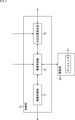
- FIG. 4 is a block diagram showing a configuration example of the moving body 10.
- the mobile body 10 includes a control unit 51, a positioning sensor 52, a communication unit 53, a drive mechanism 54, and a storage unit 55.
- the control unit 51 is composed of a processor such as a CPU (Central Processing Unit), a memory, and the like, and controls the positioning sensor 52, the communication unit 53, the drive mechanism 54, and the storage unit 55 by executing a predetermined program.
- a processor such as a CPU (Central Processing Unit), a memory, and the like, and controls the positioning sensor 52, the communication unit 53, the drive mechanism 54, and the storage unit 55 by executing a predetermined program.
- the positioning sensor 52 may be any sensor that can acquire the position of the own device (moving body 10), and is configured as, for example, a single focus camera or various positioning devices. Further, the positioning sensor 52 may be configured to include a sonar, a radar, a LiDER, and the like. The positioning data collected by the positioning sensor 52 is used, for example, to correct the self-position of the moving body 10. The positioning sensor 52 does not necessarily have to be provided.
- the communication unit 53 is composed of a network interface or the like, and performs wireless or wired communication with a controller for manipulating the mobile body 10 and any other device.
- the communication unit 53 may directly communicate with a device to be a communication partner, or may perform network communication via a base station such as Wi-Fi (registered trademark), 4G, 5G, or a repeater. Good.
- the communication unit 53 receives GPS information transmitted from a GPS (Global Positioning System) satellite.
- GPS Global Positioning System
- the drive mechanism 54 is a mechanism for moving the moving body 10.
- the moving body 10 is configured as a drone, and the drive mechanism 54 is composed of a motor, a propeller, and the like as a flight mechanism.
- the storage unit 55 is composed of a non-volatile memory such as a flash memory, and stores various information under the control of the control unit 51.
- the storage unit 55 stores the environmental structure (map) created by Visual SLAM, the image taken in the past, and the depth (three-dimensional coordinates) of the feature points on the image in association with the self-position information.
- FIG. 5 is a block diagram showing a functional configuration example of the control unit 51.
- the functional block of the control unit 51 shown in FIG. 5 is realized by executing a predetermined program by the processors constituting the control unit 51.
- the control unit 51 is composed of a drive control unit 71, an imaging control unit 72, and a self-position estimation unit 73.
- the drive control unit 71 controls the movement of the moving body 10 by controlling the drive mechanism 54.
- the image pickup control unit 72 controls the image pickup unit 20 having the zoom lens 21.
- the image captured by the imaging unit 20 is supplied to the self-position estimation unit 73.
- the image pickup control unit 72 sets the zoom parameter of the image pickup unit 20 according to the altitude of the moving body 10. It is assumed that the zoom parameters include the zoom magnification of the zoom lens 21 and the camera parameters of the imaging unit 20.
- the altitude of the moving body 10 may be acquired from the self-position estimation result of the self-position estimation unit 73, or may be acquired from the positioning data from the positioning sensor 52.
- the self-position estimation unit 73 estimates the self-position by Visual SLAM based on the image from the imaging unit 20. Further, the self-position estimation unit 73 may estimate the self-position based on the GPS information received by the communication unit 53.
- the self-position information indicating the estimated self-position is associated with the environmental structure (map) created by Visual SLAM, the image taken in the past, and the depth (three-dimensional coordinates) of the feature points on the image, and is stored in the storage unit. It is stored in 55.
- FIG. 6 is a block diagram showing a detailed configuration example of the imaging unit 20.
- the image pickup unit 20 shown in FIG. 6 includes an image sensor 91, an image processing unit 92, and a zoom lens control unit 93 in addition to the zoom lens 21.
- the image sensor 91 is composed of, for example, a CMOS (Complementary Metal Oxide Semiconductor) image sensor.
- the image sensor 91 takes in the incident light (image light) from the subject incident through the zoom lens 21, converts the amount of the incident light imaged on the imaging surface into an electric signal, and processes the image as an image signal. Output to unit 92.
- CMOS Complementary Metal Oxide Semiconductor
- the image processing unit 92 performs image correction processing such as defect correction, aberration correction, and noise reduction on the image signal from the image sensor 91. Further, the image processing unit 92 controls the zoom lens control unit 93 to perform AE (Automatic Exposure) processing for controlling exposure and contrast AF processing for controlling the focus of the zoom lens 21.
- AE Automatic Exposure
- the zoom lens control unit 93 controls the zoom lens 21 based on the zoom parameters set by the image pickup control unit 72.
- the zoom lens control unit 93 controls the servo that drives the zoom lens 21 by converting the zoom magnification among the zoom parameters into the drive control value of the zoom lens 21. That is, it can be said that the zoom parameter includes the drive control value of the zoom lens 21.
- the camera parameter among the zoom parameters is also supplied to the aberration correction circuit included in the image processing unit 92, and the aberration correction corresponding to the zoom magnification is performed. That is, it can be said that the zoom magnification is set to a desired magnification according to the camera parameters.
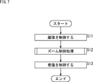
- FIG. 7 is a flowchart illustrating a flow of movement control of the moving body 10.
- step S11 the drive control unit 71 controls the takeoff of the moving body 10, that is, the start of movement (flight) by controlling the drive mechanism 54.
- step S12 the image pickup control unit 72 performs a zoom control process for setting the zoom parameters of the image pickup unit 20.
- step S13 the drive control unit 71 controls the landing of the moving body 10, that is, the end of the movement (flight) by controlling the drive mechanism 54.
- the self-position estimation unit 73 always performs self-position estimation processing for estimating the self-position by Visual SLAM based on the image captured by the image pickup unit 20 in which the zoom parameter is set.
- the moving body 10 estimates its own position while flying in the air.
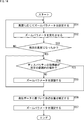
- FIG. 8 is a flowchart illustrating a zoom control process for setting zoom parameters according to altitude.
- step S31 the image pickup control unit 72 sets the zoom parameter according to the altitude of the moving body 10.
- the zoom parameter is a parameter that determines the zoom magnification (by extension, the focal length, the angle of view, and the wide end / tele end) of the zoom lens 21.
- a LUT Lookup table in which the values of the zoom parameters corresponding to the altitudes are arranged is stored in the storage unit 55, and the image pickup control unit 72 refers to the LUTs to display the zoom parameters according to the altitudes. Set.
- the zoom parameter is set so that the viewing angle is the viewing angle ⁇ 1 at which the ground surface of the area D is imaged.
- the viewing angle is the viewing angle ⁇ 2 ( ⁇ 2> ⁇ 1) in which the ground surface having the same area D as in FIG. 9 is imaged.
- the zoom parameter is set so that
- the image pickup control unit 72 sets the zoom parameter so that the viewing angle becomes smaller as the altitude of the moving body 10 increases.
- the altitude of the moving body 10 may be determined based on the self-position estimation result by the self-position estimation unit 73, or may be determined based on the positioning data collected by the positioning sensor 52.
- step S32 the image pickup control unit 72 controls the zoom lens 21 to change the zoom parameter so that the zoom parameter becomes a set value.
- step S33 the image pickup control unit 72 determines whether or not the altitude of the moving body 10 has reached a predetermined altitude.
- the predetermined altitude may be an altitude automatically set in consideration of weather conditions such as weather and wind speed, or may be an altitude determined by a preset route plan.
- step S33 the processing of steps S31 and S32, that is, the setting of the zoom parameter according to the altitude and the control of the value are repeated until it is determined that the altitude of the moving body 10 has reached a predetermined altitude. Then, when it is determined in step S33 that the altitude of the moving body 10 has reached a predetermined altitude, the process proceeds to step S34.
- step S34 the self-position estimation unit 73 corrects the estimated self-position based on the positioning data collected by the positioning sensor 52.
- the self-position estimation unit 73 registers a pair of an image and a position information as a map in the storage unit 55 in advance, and uses the position information corresponding to an image similar to the image captured by the image pickup unit 20. Correct the self-position. Further, not only the pair of the image and the position information but also the depth (three-dimensional information) of the feature points appearing in the image may be registered. In this case, the self-position estimation unit 73 derives a correspondence relationship (movement amount) between the registered image and the currently captured image, and uses the movement amount and the registered position information. Therefore, it is possible to correct the self-position with higher accuracy.
- the self-position estimation unit 73 may correct the self-position by using the GPS information received by the communication unit 53. Further, the self-position estimation unit 73 obtains the self-position by transmitting the machine ID of the moving body 10 and the captured image to an external server such as a control tower and inquiring about the position of the self-position. May be good.
- step S35 the image pickup control unit 72 fixes the zoom parameter.
- the zoom magnification of the zoom lens 21 is set to an appropriate zoom magnification.
- the trade-off between the viewing angle and the spatial resolution is eliminated by controlling the zoom magnification according to the altitude of the moving body 10. Therefore, even in an environment where it is difficult to specify the distance to the subject, it is possible to realize high accuracy in self-position estimation.
- the zoom magnification of the zoom lens 21 is set to a desired magnification by adjusting the drive control value of the servo that drives the zoom lens 21 and changing the camera parameters of the imaging unit 20.
- the camera parameters of the imaging unit 20 include internal parameters including the optical center, focal length, and distortion coefficient of the zoom lens 21, and external parameters including translation and rotation between the moving body 10 body and the imaging unit 20. Is done. Further, when the imaging unit 20 is composed of a stereo camera, the camera parameters of the imaging unit 20 include external parameters including translation and rotation between the left and right cameras.
- the drive control value of the zoom lens 21 is changed so that an image having a desired zoom magnification can be obtained even during control of the zoom lens 21 based on the correspondence as shown in FIG. Be done.
- the drive control value of the zoom lens 21 is changed at high speed, the subject may move and blur. Therefore, it is desirable to change the drive control value of the zoom lens 21 at a speed at which the subject does not move and blur.
- the camera parameters corresponding to the drive control values of the limited number of zoom lenses 21 may be acquired, and the values between the acquired camera parameters may be obtained by interpolation.
- the camera parameters of the imaging unit 20 are used for self-position estimation.
- the distortion correction is performed based on the internal parameter (distortion coefficient) corresponding to the set drive control value of the zoom lens 21.
- the position and orientation of the imaging unit 20 are obtained from the relationship between the three-dimensional coordinates and the two-dimensional coordinates on the image.
- the three-dimensional coordinates are obtained by back-projecting the two-dimensional coordinates of the depth and feature points obtained from the parallax in the reference frame f (t) using the internal parameters (optical center of the zoom lens 21 and focal length). Be done.
- the two-dimensional coordinates are obtained by detecting the feature points corresponding to the reference frame f (t) in the current frame f (t + 1).
- the internal parameters are also used when obtaining the three-dimensional coordinates in Visual SLAM.
- the external parameter between the moving body 10 main body and the imaging unit 20 is used for self-position estimation, in particular, when the moving body 10 adopts a configuration in which a positioning device is mounted in addition to the imaging unit 20.
- the configuration of the mobile body 10 on which the positioning device is mounted will be described later.
- zoom control process flow 2> By the way, in the zoom control process described above, the zoom parameter is set according to the altitude, but the zoom parameter may be further adjusted according to the moving speed of the moving body 10.
- FIG. 12 is a flowchart illustrating a zoom control process for adjusting a zoom parameter according to a moving speed.
- steps S41 to S43, S45, and S46 of the flowchart of FIG. 12 is the same as the processing of steps S31 to S35 of the flowchart of FIG. 8, so the description thereof will be omitted.
- step S44 the image pickup control unit 72 controls the zoom lens 21 to set the zoom parameter according to the moving speed. adjust.
- the moving speed here is the maximum speed automatically set in consideration of weather conditions such as weather and wind speed, or the maximum speed determined by a preset route plan.
- the zoom parameter is adjusted so that the viewing angle becomes large. .. This enables the frame I and t-1 of the subject, the portion that overlaps the subject frame I t at time t at time t-1.
- the zoom parameter is adjusted so that the viewing angle becomes small. ..
- the moving speed is not so high, even with a small viewing angle, it is the frame I and t-1 of the subject, the portion that overlaps the subject frame I t at time t at time t-1.
- the imaging control unit 72 adjusts the zoom parameter so that the higher the moving speed of the moving body 10, the larger the viewing angle.
- the zoom parameter is adjusted according to the maximum speed of the moving body 10, but the actual moving speed is detected while the moving body 10 is moving, and it is adaptive according to the moving speed.
- the zoom parameter may be adjusted to.
- the body of the moving body 10 may tilt.
- driving the gimbal GB cancels the inclination of the moving body 10 and keeps the imaging unit 20 in a constant orientation with respect to the ground surface. As described above, the position and orientation of the imaging unit 20 may be controlled.
- the zoom parameter is adjusted according to both the altitude and the moving speed of the moving body 10, but the zoom parameter is adjusted according to either the altitude or the moving speed of the moving body 10. It may be adjusted.
- zoom control process flow 3> The zoom parameter may be adjusted according to the disparity of the image captured by the imaging unit 20.
- FIG. 14 is a flowchart illustrating a zoom control process for adjusting a zoom parameter according to the disparity of the image.
- steps S51 to S53, S56, and S57 of the flowchart of FIG. 14 is the same as the processing of steps S31 to S35 of the flowchart of FIG. 8, so the description thereof will be omitted.
- step S54 the image pickup control unit 72 determines whether or not the index value of the disparity of the feature points on the image imaged by the image pickup unit 20 is within a predetermined range.
- the wider the zoom lens the smaller the disparity of the feature points in the distance, and the lower the depth resolution.
- the disparity is 0.5 pix or less, the depth is buried in the noise of the image, and accurate positioning cannot be performed.
- the image pickup control unit 72 obtains the disparity of the feature points of the entire image.
- the imaging unit 20 is composed of a monocular camera, as shown in A of FIG. 15, a point corresponding to the feature points in the frame I t-1 at time t-1, epipolar line in the frame I t at time t By searching with, the disparity of the feature points can be obtained.
- the imaging unit 20 is composed of a stereo camera, as shown in B of FIG. 15, points corresponding to the feature points in the right eye image Ilit of the stereo image are located on the epipolar line in the left eye image Ileft. By searching, the disparity of the feature points can be obtained.
- the image pickup control unit 72 determines whether or not the average value of the disparity of the feature points of the entire image is within a predetermined range.
- step S55 the imaging control unit 72 determines that the average value of the disparity of the feature points of the entire image is the value. Adjust the zoom parameter (viewing angle) so that the value falls within the specified range. After that, the process returns to step S54, and step S55 is repeated until it is determined that the average value of the disparity of the feature points of the entire image is within a predetermined range.
- the viewing angle may be controlled so that the representative value of the disparity of the feature points of the entire image is within a predetermined range, not limited to the average value of the disparity of the feature points of the entire image.
- the representative value of the disparity may be the disparity of the feature points stably detected in the image, or the disparity of the feature points in the region in the center of the screen.
- a representative value of disparity may be obtained by weighting each feature point of the image and calculating the weighted average.
- step S55 is skipped and the process proceeds to step S56.
- the image pickup control unit 72 further adjusts the zoom parameter according to the index value of the disparity of the feature points on the image captured by the image pickup unit 20.
- the depth of the feature points on the image can be obtained with high accuracy, so that the accuracy of self-position estimation can be maintained.
- the zoom parameter is adjusted based on the disparity index value after the altitude change of the moving body 10, but the disparity index value obtained during the movement of the moving body 10 is assumed.
- the zoom parameters may be adaptively adjusted accordingly.
- the zoom parameter may be adjusted based on the index value of disparity after the zoom parameter is adjusted according to at least one of the altitude and the moving speed as well as the altitude of the moving body 10.
- zoom control process flow 4> The zoom parameter may be adjusted according to the overlap rate between the frames of the images captured by the imaging unit 20.
- FIG. 16 is a flowchart illustrating a zoom control process for adjusting a zoom parameter according to an overlap rate between frames of an image.
- steps S61 to S63, S66, and S67 in the flowchart of FIG. 16 is the same as the processing of steps S31 to S35 of the flowchart of FIG. 8, so the description thereof will be omitted.
- step S64 the imaging control unit 72 determines whether or not the overlap rate between frames of the images captured by the imaging unit 20 is equal to or less than a predetermined threshold value.
- the match between the frame I t at time t is performed.
- the overlap rate OLR is expressed by the following equation (1).
- the denominator in equation (1) is the number of pixels in the texture area on the frame I t-1, molecules in the formula (1) is, in FIG. 17, the matching between the frame I t-1 and the frame I t It is the number of pixels of the matched texture area 100.
- the overlap ratio OLR is between the frame I t-1 and the frame I in addition be represented using any of a number of pixels of the texture region matched with the t, frame I t-1 and the frame I t It may be expressed using the number of feature points matched by.
- step S65 When it is determined that the overlap rate thus obtained is equal to or less than a predetermined threshold value, the process proceeds to step S65, and the imaging control unit 72 adjusts the zoom parameter so that the viewing angle becomes large. After that, the process returns to step S64, and step S65 is repeated until it is determined that the overlap rate is not equal to or less than a predetermined threshold value.
- step S65 is skipped and the process proceeds to step S66.
- the image pickup control unit 72 further adjusts the zoom parameter according to the overlap rate between the frames of the images captured by the image pickup unit 20.
- the zoom parameter is adjusted based on the overlap rate after the altitude change of the moving body 10, but it is adapted according to the overlap rate obtained during the movement of the moving body 10.
- the zoom parameter may be adjusted.
- the zoom parameter may be adjusted based on the overlap rate after the zoom parameter is adjusted according to at least one of the altitude and the moving speed as well as the altitude of the moving body 10.
- the moving body 10 may be equipped with a positioning device 120 in addition to the imaging unit 20.
- the positioning device 120 corresponds to the positioning sensor 52 of FIG. 4, and is, for example, any one of devices such as a single focus camera, an RTK (Real Time Kinetic) positioning device, a GPS positioning device, and an IMU (Inertial Measurement Unit), or these. It is composed of a combination of.
- step S71 it is determined whether or not the zoom control process by the image pickup control unit 72 has been started.
- step S72 The process does not proceed until it is determined that the zoom control process has started, and when it is determined that the zoom control process has started, the process proceeds to step S72.
- step S72 the self-position estimation unit 73 lowers the reliability of self-position estimation using the zoom camera image, which is an image captured by the imaging unit 20.
- step S73 it is determined whether or not the zoom control process by the image pickup control unit 72 is completed.
- Step S73 is repeated until it is determined that the zoom control process has been completed. That is, the self-position estimation is performed with the reliability of the self-position estimation using the zoom camera image lowered until the zoom control process is completed and the zoom parameter is fixed.
- step S75 the process proceeds to step S75.
- step S74 the self-position estimation unit 73 restores the reliability of self-position estimation using the zoom camera image.
- the self-position estimation is performed with the reliability of the self-position estimation using the zoom camera image lowered, so that the altitude of the moving body 10 changes. While doing so, it is possible to accurately estimate the self-position.
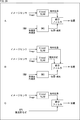
- FIG. 20 is a diagram illustrating integration of self-position estimation results using output data of a plurality of devices.
- FIG. 20A integrates the result of Visual SLAM using the image from the image sensor (single focus camera) and the position / velocity calculated by INS (Inertial Navigation System) based on the acceleration / angular velocity from the IMU. The configuration is shown.
- INS Inertial Navigation System
- the self-position is estimated by integrating the relative position, which is the result of Visual SLAM, and the position / velocity calculated by INS by the integrated filter.
- the integrated filter for example, a Kalman filter can be used.
- FIG. 20 shows a configuration in which each of the results of Visual SLAM using images from two image sensors and the position / velocity calculated by INS based on the acceleration / angular velocity from the IMU are integrated.
- the self-position is estimated by integrating each of the relative positions, which is the result of Visual SLAM, and the position / velocity calculated by INS by the integrated filter.
- C in FIG. 20 shows a configuration that integrates the result of Visual SLAM using the image from the image sensor and the position and altitude measured by the GPS sensor and the altimeter.
- the self-position is estimated by integrating the relative position, which is the result of Visual SLAM, and the position and altitude measured by the GPS sensor and the altimeter by the integrated filter.
- the self-position may be estimated by integrating the self-position estimation results using the output data of a plurality of devices.
- the self-position estimation result (low reliability) using the image captured by the imaging unit 20 and the self-position estimation result using the output data of the positioning device 120 may be integrated.
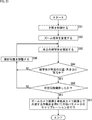
- FIG. 21 is a flowchart illustrating a flow of calibration of internal parameters. The process of FIG. 21 is executed, for example, when the moving body 10 in flight reaches the sky above a predetermined destination. For example, a subject (calibration board, etc.) on which a known pattern is drawn is arranged on the ground surface of the destination.
- step S81 the drive control unit 71 controls the descent of the moving body 10 by controlling the drive mechanism 54.
- the posture of the imaging unit 20 is controlled by the arm CA so that the optical axis of the zoom lens 21 of the imaging unit 20 is fixed in the vertical direction (depression angle 90 °).
- step S82 the imaging control unit 72 controls the zoom lens 21 to change the zoom magnification to the zoom magnification to be calibrated.
- step S83 the image pickup control unit 72 takes an image of a subject on the ground by controlling the image pickup unit 20.
- step S84 it is determined whether or not the subject appears at a predetermined position and size.
- step S84 If it is determined in step S84 that the subject is captured at a predetermined position and size, the process proceeds to step S85.
- step S85 it is determined whether or not the imaging unit 20 has imaged a subject on the ground a predetermined number of times.
- step S84 if it is determined in step S84 that the subject is not captured at a predetermined position and size, or if it is determined in step S85 that the imaging unit 20 has not captured a predetermined number of times, the process proceeds to step S86 and the shooting position. Is adjusted.
- the altitude of the moving body 10 is changed so that the subject appears in the predetermined position / size.
- the positions and postures of the moving body 10 and the imaging unit 20 may be changed up, down, left and right.
- step S86 when the subject is captured at a predetermined position and size and the imaging unit 20 images the subject a predetermined number of times, the process proceeds to step S86.
- step S86 the imaging control unit 72 calibrates the internal parameters using a plurality of images obtained by imaging a predetermined number of times.
- the above processing is executed for the zoom magnification that you want to calibrate. Therefore, when there are a plurality of zoom magnifications to be calibrated, the process of FIG. 21 is repeatedly executed for each zoom magnification.
- the process of FIG. 21 is executed when the moving body 10 in flight reaches the sky above a predetermined destination, but it is moved by arranging the subject on the ground surface of the departure point.
- Body 10 may be performed when taking off from the starting point.
- FIG. 23 is a flowchart illustrating a flow of calibration of external parameters between the main body of the moving body 10 and the imaging unit 20. The process of FIG. 23 is executed in a state where the mobile body 10 including the positioning device 120 described with reference to FIG. 18 is moving over, for example, a takeoff point (starting point) or a landing point (destination). To.
- process of FIG. 23 may be executed in parallel with the calibration of the internal parameters of FIG. 21, or may be executed separately from the calibration of the internal parameters of FIG. 21.
- steps S91 to S96 of FIG. 23 is basically the same as the processing in steps S81 to S86 of FIG. 21, so the description thereof will be omitted.
- the optical axis of the zoom lens 21 of the imaging unit 20 may be fixed in the vertical direction (depression angle of 90 °) or may be fixed in any direction.
- the external parameters include the deviation of the optical axis inside the imaging unit 20 including the zoom lens 21 and the deviation of the inclination of the arm CA.
- the optical axis of the zoom lens 21 is fixed in the vertical direction (depression angle 90 °) by the arm CA, and only the deviation of the optical axis inside the imaging unit 20 due to aged deterioration is calibrated. Can be executed.
- step S97 the image pickup control unit 72 uses the feature points common to the zoom camera image captured by the image pickup unit 20 and the single focus camera image captured by the single focus camera constituting the positioning device 120. , Calibrate the external parameters.
- the process of FIG. 24 is also executed in a state where the mobile body 10 including the positioning device 120 is moving over the takeoff point or the landing point.
- step S101 the drive control unit 71 controls the drive mechanism 54 so as to move on a pre-registered route (to make an optimum movement for performing calibration of external parameters). Control the movement of.
- step S102 the self-position estimation unit 73 performs self-position estimation using the zoom camera image captured by the image pickup unit 20.
- step S103 the self-position estimation unit 73 performs self-position estimation using the single-focus camera image captured by the single-focus cameras constituting the positioning device 120.
- step S104 the imaging control unit 72 calibrates the external parameters so that the self-position estimation result using the zoom camera image and the self-position estimation result using the single focus camera image match. Specifically, the imaging control unit 72 calibrates the external parameters by solving an optimization problem in which the external parameters are used as variables.
- the posture of the image pickup unit 20 is kept constant, so that the zoom lens 21 and the single focus camera are used.
- the relative positional relationship with (positioning device 120) is not kept constant. In this case, it is assumed that the small posture change of the moving body 10 is performed by the single focus camera, and the posture relative to the imaging unit 20 can be obtained from the posture at any time.
- the external parameters affect the integrated result of integrating the self-position estimation result using the zoom camera image captured by the imaging unit 20 and the self-position estimation result using the single-focus camera captured by the single-focus camera. To exert.
- the moving body 10 of the present technology since the external parameters are calibrated, even if the camera parameters change, the maintenance can be performed regularly, and the self-positioning with high accuracy can be performed. It is possible to maintain the state of performing estimation.
- control unit 51 of the moving body 10 controls the zoom parameters of the imaging unit 20 to estimate the self-position.
- an external computer that controls the moving body 10 may control the zoom parameter of the imaging unit 20 to estimate the position of the moving body 10.
- FIG. 25 is a diagram showing a configuration example of a control system for the mobile body 10.
- the mobile body 10 wirelessly communicates with the controller 210 and the mobile terminal 220 for manipulating the mobile body 10.
- the controller 210 and the mobile terminal 220 include a control unit having the same function as the control unit 51, and set the zoom parameter of the imaging unit 20 according to at least one of the altitude and the moving speed of the moving body 10. , The self-position is estimated based on the image from the imaging unit 20.
- FIG. 25 is a block diagram showing a configuration example of computer hardware.
- the controller 210 and the mobile terminal 220 described above are realized by a computer having the configuration shown in FIG. 25.
- the CPU 1001, ROM 1002, and RAM 1003 are connected to each other by the bus 1004.
- An input / output interface 1005 is further connected to the bus 1004.
- An input unit 1006 including a keyboard and a mouse, and an output unit 1007 including a display and a speaker are connected to the input / output interface 1005.
- the input / output interface 1005 is connected to a storage unit 1008 including a hard disk and a non-volatile memory, a communication unit 1009 including a network interface, and a drive 310 for driving the removable media 1011.
- the CPU 1001 loads and executes the program stored in the storage unit 1008 into the RAM 1003 via the input / output interface 1005 and the bus 1004, thereby executing the above-mentioned series of processes. Is done.
- the program executed by the CPU 1001 is recorded on the removable media 311 or provided via a wired or wireless transmission medium such as a local area network, the Internet, or digital broadcasting, and installed in the storage unit 1008.
- a wired or wireless transmission medium such as a local area network, the Internet, or digital broadcasting
- the program executed by the computer may be a program in which processing is performed in chronological order in the order described in this specification, or in parallel or at a necessary timing such as when a call is made. It may be a program in which processing is performed.
- the technique according to the present disclosure may have the following configuration.
- the image pickup control unit changes the zoom parameter so that the viewing angle becomes smaller as the altitude of the own machine increases.
- the imaging control unit adjusts the zoom parameter so that the viewing angle increases as the moving speed of the own machine increases.
- the imaging unit is composed of a monocular camera.
- the imaging unit is composed of a stereo camera.
- the zoom parameter includes an internal parameter and an external parameter of the imaging unit.
- the internal parameter includes a distortion coefficient of the zoom lens.
- the zoom parameters of the imaging unit are set according to at least one of the altitude and the moving speed of the moving body including the imaging unit having a zoom lens.
- To the processor The zoom parameters of the imaging unit are set according to at least one of the altitude and the moving speed of the moving body including the imaging unit having a zoom lens.
Abstract
The present disclosure relates to a mobile body, a position estimation method, and a program, which enable highly precise localization. An image-capturing control unit sets a zoom parameter of an image-capturing unit that has a zoom lens, in accordance with at least one of altitude and traveling velocity of an own craft; and a localization unit estimates an own position on the basis of an image captured by the image-capturing unit of which the zoom parameter has been set. The feature according to the present disclosure is applicable to a mobile body such as a drone, for example.
Description
本開示は、移動体、位置推定方法、およびプログラムに関し、特に、自己位置推定の高精度化を実現することができるようにする移動体、位置推定方法、およびプログラムに関する。
The present disclosure relates to a mobile body, a position estimation method, and a program, and more particularly to a mobile body, a position estimation method, and a program that enable high accuracy of self-position estimation.
近年、移動体において、カメラから得られる画像を用いて自己位置を推定するとともに、周囲の環境構造(マップ)を取得するVisual SLAM(Simultaneous Localization And Mapping)と呼ばれる技術が知られている。
In recent years, a technique called Visual SLAM (Simultaneous Localization And Mapping) has been known for estimating the self-position of a moving body using an image obtained from a camera and acquiring the surrounding environmental structure (map).
例えば非特許文献1には、単眼カメラを用いたSLAM技術が開示されている。
For example, Non-Patent Document 1 discloses SLAM technology using a monocular camera.
通常、自己位置推定を行うためには、カメラの移動前と移動後とで、カメラの画角内に共通の被写体が写っている必要がある。
Normally, in order to estimate the self-position, it is necessary that a common subject is captured within the angle of view of the camera before and after the camera is moved.
カメラの画角については、視野角と空間分解能(距離精度)とがトレードオフとなることが一般的に知られている。
It is generally known that there is a trade-off between the viewing angle and the spatial resolution (distance accuracy) of the angle of view of the camera.
空中を飛行するドローンは、地上を移動する車両などと異なり、地表の近くから上空まであらゆる環境を移動することができる。そのため、ドローンにおいて自己位置推定を行う場合、被写体までの距離が遠くなることで空間分解能(距離精度)が不足し、自己位置推定の精度が低下してしまう。
Drones that fly in the air can move in any environment from near the surface of the earth to the sky, unlike vehicles that move on the ground. Therefore, when self-position estimation is performed in a drone, the spatial resolution (distance accuracy) becomes insufficient as the distance to the subject becomes long, and the self-position estimation accuracy deteriorates.
本開示は、このような状況に鑑みてなされたものであり、自己位置推定の高精度化を実現することができるようにするものである。
This disclosure has been made in view of such a situation, and is intended to enable high accuracy of self-position estimation.
本開示の移動体は、ズームレンズを有する撮像部と、自機の高度および移動速度の少なくともいずれかに応じて、前記撮像部のズームパラメータを設定する撮像制御部と、前記ズームパラメータが設定された前記撮像部により撮像された画像に基づいて、自己位置を推定する自己位置推定部とを備える移動体である。ズームパラメータには、ズームレンズのズーム倍率、撮像部のカメラパラメータが含まれる。
In the moving body of the present disclosure, an imaging unit having a zoom lens, an imaging control unit that sets the zoom parameters of the imaging unit according to at least one of the altitude and the moving speed of the own machine, and the zoom parameters are set. It is a moving body including a self-position estimation unit that estimates a self-position based on an image captured by the image pickup unit. The zoom parameters include the zoom magnification of the zoom lens and the camera parameters of the imaging unit.
本開示の位置推定方法は、ズームレンズを有する撮像部を備える移動体の高度および移動速度の少なくともいずれかに応じて、前記撮像部のズームパラメータを設定し、前記ズームパラメータが設定された前記撮像部により撮像された画像に基づいて、前記移動体の位置を推定する位置推定方法である。
In the position estimation method of the present disclosure, the zoom parameters of the imaging unit are set according to at least one of the altitude and the moving speed of the moving body including the imaging unit having a zoom lens, and the imaging with the zoom parameters set. This is a position estimation method for estimating the position of the moving body based on the image captured by the unit.
本開示のプログラムは、プロセッサに、ズームレンズを有する撮像部を備える移動体の高度および移動速度の少なくともいずれかに応じて、前記撮像部のズームパラメータを設定し、前記ズームパラメータが設定された前記撮像部により撮像された画像に基づいて、前記移動体の位置を推定する処理を実行させるためのプログラムである。
The program of the present disclosure sets the zoom parameter of the image pickup unit according to at least one of the altitude and the movement speed of the moving body including the image pickup unit having the zoom lens in the processor, and the zoom parameter is set. This is a program for executing a process of estimating the position of the moving body based on the image captured by the imaging unit.
本開示においては、ズームレンズを有する撮像部を備える移動体の高度および移動速度の少なくともいずれかに応じて、前記撮像部のズームパラメータが設定され、前記ズームパラメータが設定された前記撮像部により撮像された画像に基づいて、前記移動体の位置が推定される。
In the present disclosure, the zoom parameters of the imaging unit are set according to at least one of the altitude and the moving speed of the moving body including the imaging unit having the zoom lens, and the image pickup unit with the zoom parameters set the image. The position of the moving body is estimated based on the image.
以下、本開示を実施するための形態(以下、実施の形態という)について説明する。なお、説明は以下の順序で行う。
Hereinafter, a mode for implementing the present disclosure (hereinafter referred to as an embodiment) will be described. The explanation will be given in the following order.
1.Visual SLAMと本開示に係る技術の概要
2.移動体の構成と移動制御
3.ズーム制御処理の流れ1(高度に応じたズームパラメータ設定)
4.ズーム制御処理の流れ2(移動速度に応じたズームパラメータ調整)
5.ズーム制御処理の流れ3(ディスパリティに応じたズームパラメータ調整)
6.ズーム制御処理の流れ4(オーバーラップ率に応じたズームパラメータ調整)
7.測位デバイスを備える移動体の構成
8.キャリブレーションの流れ
9.移動体の制御システムの構成 1. 1. Outline of Visual SLAM and the technology related to this disclosure 2. Structure of moving body and movement control 3. Zoom control process flow 1 (zoom parameter setting according to altitude)
4. Zoom control process flow 2 (Zoom parameter adjustment according to moving speed)
5. Zoom control process flow 3 (Zoom parameter adjustment according to disparity)
6. Zoom control process flow 4 (Zoom parameter adjustment according to overlap rate)
7. Configuration of a mobile body equipped with a positioning device 8. Calibration flow 9. Configuration of mobile control system
<1.Visual SLAMと本開示に係る技術の概要>
Visual SLAMは、カメラから得られる画像を用いて自己位置を推定するとともに、周囲の環境構造(マップ)を取得する技術である。 <1. Outline of Visual SLAM and the technology related to this disclosure>
Visual SLAM is a technology that estimates the self-position using an image obtained from a camera and acquires the surrounding environmental structure (map).
Visual SLAMは、カメラから得られる画像を用いて自己位置を推定するとともに、周囲の環境構造(マップ)を取得する技術である。 <1. Outline of Visual SLAM and the technology related to this disclosure>
Visual SLAM is a technology that estimates the self-position using an image obtained from a camera and acquires the surrounding environmental structure (map).
Visual SLAMにおいてステレオカメラを用いる場合、左右のステレオ画像に写った特徴点の視差から被写体までの距離と方向が推定され、それらの特徴点の時間的変動から、カメラの移動量が推定される。
When a stereo camera is used in Visual SLAM, the distance and direction to the subject are estimated from the parallax of the feature points in the left and right stereo images, and the amount of movement of the camera is estimated from the temporal fluctuation of those feature points.
Visual SLAMにおいて単眼カメラを用いる場合、単眼カメラ自身の移動量に基づいて、連続するフレーム間に写った特徴点の視差から被写体までの距離と方向が推定され、それらの特徴点の時間的変動から、カメラの移動量が推定される。
When a monocular camera is used in Visual SLAM, the distance and direction to the subject are estimated from the parallax of the feature points captured between consecutive frames based on the movement amount of the monocular camera itself, and from the temporal fluctuation of those feature points. , The amount of movement of the camera is estimated.
単眼カメラを用いる場合、自身の移動量に基づいて視差を作り出す必要があるが、最初の移動量を推定するには、大きさが既知の被写体を撮像しながら移動を開始させたり、他の測距デバイスを用いて最初の移動量を決定したりするなどの初期化が必要となる。
When using a monocular camera, it is necessary to create parallax based on its own movement amount, but to estimate the initial movement amount, start movement while imaging a subject of known size, or use other measurements. Initialization is required, such as determining the initial amount of movement using a parallax device.
ステレオカメラを用いる場合であっても、単眼カメラを用いる場合であっても、自己位置推定を行うためには、カメラの移動前と移動後とで、カメラの画角内に共通の被写体が写っている必要がある。
Regardless of whether a stereo camera is used or a monocular camera is used, in order to perform self-position estimation, a common subject is captured within the angle of view of the camera before and after the camera is moved. Must be.
カメラの画角については、視野角と空間分解能(距離精度)とがトレードオフとなることが一般的に知られている。
It is generally known that there is a trade-off between the viewing angle and the spatial resolution (distance accuracy) of the angle of view of the camera.
空中を飛行するドローンは、地上を移動する車両などと異なり、地表の近くから上空まであらゆる環境を移動することができる。そのため、ドローンにおいて自己位置推定を行う場合、被写体までの距離が遠くなることで空間分解能(距離精度)が不足し、自己位置推定の精度が低下してしまう。
Drones that fly in the air can move in any environment from near the surface of the earth to the sky, unlike vehicles that move on the ground. Therefore, when self-position estimation is performed in a drone, the spatial resolution (distance accuracy) becomes insufficient as the distance to the subject becomes long, and the self-position estimation accuracy deteriorates.
そこで、本開示に係る技術を適用した移動体は、高度に応じてズームレンズのズーム倍率を適切に制御することで、被写体までの距離を規定し難い環境下であっても、自己位置推定の高精度化を実現するように構成される。
Therefore, the moving body to which the technique according to the present disclosure is applied can estimate the self-position even in an environment where it is difficult to specify the distance to the subject by appropriately controlling the zoom magnification of the zoom lens according to the altitude. It is configured to achieve high accuracy.
<2.移動体の構成と移動制御>
(移動体の外観)
図1は、本開示に係る技術(本技術)を適用した移動体の外観を示す図である。 <2. Mobile configuration and movement control>
(Appearance of moving body)
FIG. 1 is a diagram showing the appearance of a moving body to which the technique according to the present disclosure (the present technique) is applied.
(移動体の外観)
図1は、本開示に係る技術(本技術)を適用した移動体の外観を示す図である。 <2. Mobile configuration and movement control>
(Appearance of moving body)
FIG. 1 is a diagram showing the appearance of a moving body to which the technique according to the present disclosure (the present technique) is applied.
図1に示される移動体10はドローンとして構成される。移動体10は、例えば、あらかじめ設定された飛行経路に従って自律移動(自律飛行)する。移動体には、自律移動するドローンや車両、船舶、掃除機などの自律移動ロボットに加え、移動体に付属して移動する機器なども含まれる。以下においては、本開示に係る技術を、空中を飛行するドローンに適用した例について説明するが、本開示に係る技術は、ドローンの他、陸上を移動する自律走行車両、水上または水中を移動する自律航行船舶、屋内を移動する自律移動掃除機などの自律移動ロボットに適用することが可能である。
The mobile body 10 shown in FIG. 1 is configured as a drone. For example, the moving body 10 autonomously moves (autonomous flight) according to a preset flight path. The moving body includes autonomous moving robots such as drones, vehicles, ships, and vacuum cleaners that move autonomously, as well as devices that move attached to the moving body. In the following, an example in which the technology according to the present disclosure is applied to a drone flying in the air will be described. However, the technology according to the present disclosure includes a drone, an autonomous vehicle moving on land, and moving on or under water. It can be applied to autonomous mobile robots such as autonomous navigation vessels and autonomous mobile vacuum cleaners that move indoors.
移動体10には、自己位置推定を行うための画像を撮像する撮像部が搭載される。
The moving body 10 is equipped with an imaging unit that captures an image for self-position estimation.
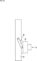
図2に示されるように、移動体10に搭載される撮像部20は、移動体10の機体底面に、電子駆動可能なアームCAを介して接続される。撮像部20は、アームCAの関節によって俯角方向にその光軸を制御できる機構を備えている。これにより、撮像部20の光軸は、少なくとも鉛直方向(俯角90°)から水平方向(俯角0°)の間に固定される。
As shown in FIG. 2, the imaging unit 20 mounted on the moving body 10 is connected to the bottom surface of the moving body 10 via an electronically driveable arm CA. The imaging unit 20 has a mechanism capable of controlling its optical axis in the depression angle direction by the joint of the arm CA. As a result, the optical axis of the imaging unit 20 is fixed at least between the vertical direction (depression angle 90 °) and the horizontal direction (depression angle 0 °).
撮像部20は、ズームレンズ21を有している。詳細は後述するが、ズームレンズ21は、移動体10の高度に応じてそのズーム倍率が制御される。撮像部20は、単眼カメラで構成されてもよいしステレオカメラで構成されてもよい。
The imaging unit 20 has a zoom lens 21. The details of the zoom lens 21 will be described later, but the zoom magnification of the zoom lens 21 is controlled according to the altitude of the moving body 10. The imaging unit 20 may be composed of a monocular camera or a stereo camera.
また、図3に示されるように、撮像部20は、移動体10の機体底面に、電子駆動可能なジンバルGBを介して接続されるようにしてもよい。図3の例では、ジンバルGBは3軸の回転軸を有し、撮像部20は、ジンバルGBによって俯角、方位角、および傾斜角の3方向に、その光軸を制御できる構成を備えている。ジンバルGBの回転軸は、必要に応じて、3軸のうちのいずれかに制限されてもよい。
Further, as shown in FIG. 3, the imaging unit 20 may be connected to the bottom surface of the moving body 10 via an electronically driveable gimbal GB. In the example of FIG. 3, the gimbal GB has a three-axis rotation axis, and the imaging unit 20 has a configuration in which the optical axis can be controlled by the gimbal GB in three directions of depression angle, azimuth angle, and inclination angle. .. The rotation axis of the gimbal GB may be limited to any of the three axes, if necessary.
撮像部20がジンバルGBを介して接続される構成により、移動体10の機体が傾いた場合であっても、撮像部20の姿勢を一定に保つことができる。
Due to the configuration in which the imaging unit 20 is connected via the gimbal GB, the posture of the imaging unit 20 can be kept constant even when the body of the moving body 10 is tilted.
なお、一般的なドローンには、ジンバルを介して接続された空撮用カメラが搭載されることがある。この空撮用カメラが本技術の移動体10に搭載される場合には、撮像部20は、空撮用カメラに剛体接続されるようにしてもよい。
Note that a general drone may be equipped with an aerial camera connected via a gimbal. When this aerial photography camera is mounted on the mobile body 10 of the present technology, the imaging unit 20 may be rigidly connected to the aerial photography camera.
(移動体の構成ブロック)
図4は、移動体10の構成例を示すブロック図である。 (Movement block)
FIG. 4 is a block diagram showing a configuration example of the movingbody 10.
図4は、移動体10の構成例を示すブロック図である。 (Movement block)
FIG. 4 is a block diagram showing a configuration example of the moving
移動体10は、制御部51、測位センサ52、通信部53、駆動機構54、および記憶部55を備えている。
The mobile body 10 includes a control unit 51, a positioning sensor 52, a communication unit 53, a drive mechanism 54, and a storage unit 55.
制御部51は、CPU(Central Processing Unit)などのプロセッサやメモリなどで構成され、所定のプログラムを実行することにより、測位センサ52、通信部53、駆動機構54、および記憶部55を制御する。
The control unit 51 is composed of a processor such as a CPU (Central Processing Unit), a memory, and the like, and controls the positioning sensor 52, the communication unit 53, the drive mechanism 54, and the storage unit 55 by executing a predetermined program.
測位センサ52は、自機(移動体10)の位置を取得可能なセンサであればよく、例えば、単焦点カメラや各種の測位デバイスなどとして構成される。また、測位センサ52は、ソナー、レーダやLiDERなどを含むようにして構成されてもよい。測位センサ52により収集された測位データは、例えば、移動体10の自己位置の補正に用いられる。測位センサ52は、必ずしも設けられなくともよい。
The positioning sensor 52 may be any sensor that can acquire the position of the own device (moving body 10), and is configured as, for example, a single focus camera or various positioning devices. Further, the positioning sensor 52 may be configured to include a sonar, a radar, a LiDER, and the like. The positioning data collected by the positioning sensor 52 is used, for example, to correct the self-position of the moving body 10. The positioning sensor 52 does not necessarily have to be provided.
通信部53は、ネットワークインタフェースなどで構成され、移動体10を操縦するためのコントローラや、その他の任意の装置との間で、無線または有線による通信を行う。例えば、通信部53は、通信相手となる装置と、直接通信を行ってもよいし、Wi-Fi(登録商標)や4G,5Gなどの基地局や中継器を介したネットワーク通信を行ってもよい。また、通信部53は、GPS(Global Positioning System)衛星から送信されてくるGPS情報を受信する。
The communication unit 53 is composed of a network interface or the like, and performs wireless or wired communication with a controller for manipulating the mobile body 10 and any other device. For example, the communication unit 53 may directly communicate with a device to be a communication partner, or may perform network communication via a base station such as Wi-Fi (registered trademark), 4G, 5G, or a repeater. Good. In addition, the communication unit 53 receives GPS information transmitted from a GPS (Global Positioning System) satellite.
駆動機構54は、移動体10を移動させるための機構である。この例では、移動体10はドローンとして構成され、駆動機構54は、飛行機構としてのモータやプロペラなどから構成される。
The drive mechanism 54 is a mechanism for moving the moving body 10. In this example, the moving body 10 is configured as a drone, and the drive mechanism 54 is composed of a motor, a propeller, and the like as a flight mechanism.
記憶部55は、フラッシュメモリなどの不揮発性メモリなどにより構成され、制御部51の制御に従い、各種の情報を記憶する。例えば、記憶部55は、Visual SLAMにより作成された環境構造(マップ)や過去に撮影した画像、画像上の特徴点の奥行き(3次元座標)を、自己位置情報と対応付けて記憶する。
The storage unit 55 is composed of a non-volatile memory such as a flash memory, and stores various information under the control of the control unit 51. For example, the storage unit 55 stores the environmental structure (map) created by Visual SLAM, the image taken in the past, and the depth (three-dimensional coordinates) of the feature points on the image in association with the self-position information.
(制御部の機能構成ブロック)
図5は、制御部51の機能構成例を示すブロック図である。 (Functional configuration block of control unit)
FIG. 5 is a block diagram showing a functional configuration example of thecontrol unit 51.
図5は、制御部51の機能構成例を示すブロック図である。 (Functional configuration block of control unit)
FIG. 5 is a block diagram showing a functional configuration example of the
図5に示される制御部51の機能ブロックは、制御部51を構成するプロセッサにより所定のプログラムが実行されることによって実現される。
The functional block of the control unit 51 shown in FIG. 5 is realized by executing a predetermined program by the processors constituting the control unit 51.
制御部51は、駆動制御部71、撮像制御部72、および自己位置推定部73から構成される。
The control unit 51 is composed of a drive control unit 71, an imaging control unit 72, and a self-position estimation unit 73.
駆動制御部71は、駆動機構54を制御することで、移動体10の移動を制御する。
The drive control unit 71 controls the movement of the moving body 10 by controlling the drive mechanism 54.
撮像制御部72は、ズームレンズ21を有する撮像部20を制御する。撮像部20により撮像された画像は、自己位置推定部73に供給される。
The image pickup control unit 72 controls the image pickup unit 20 having the zoom lens 21. The image captured by the imaging unit 20 is supplied to the self-position estimation unit 73.
また、撮像制御部72は、移動体10の高度に応じて、撮像部20のズームパラメータを設定する。ズームパラメータは、ズームレンズ21のズーム倍率と、撮像部20のカメラパラメータを含むものとする。移動体10の高度は、自己位置推定部73の自己位置推定結果から取得されてもよいし、測位センサ52からの測位データから取得されてもよい。
Further, the image pickup control unit 72 sets the zoom parameter of the image pickup unit 20 according to the altitude of the moving body 10. It is assumed that the zoom parameters include the zoom magnification of the zoom lens 21 and the camera parameters of the imaging unit 20. The altitude of the moving body 10 may be acquired from the self-position estimation result of the self-position estimation unit 73, or may be acquired from the positioning data from the positioning sensor 52.
自己位置推定部73は、撮像部20からの画像に基づいて、Visual SLAMにより自己位置を推定する。また、自己位置推定部73は、通信部53により受信されたGPS情報に基づいて、自己位置を推定してもよい。推定された自己位置を示す自己位置情報は、Visual SLAMにより作成された環境構造(マップ)や過去に撮影した画像、画像上の特徴点の奥行き(3次元座標)と対応付けられて、記憶部55に記憶される。
The self-position estimation unit 73 estimates the self-position by Visual SLAM based on the image from the imaging unit 20. Further, the self-position estimation unit 73 may estimate the self-position based on the GPS information received by the communication unit 53. The self-position information indicating the estimated self-position is associated with the environmental structure (map) created by Visual SLAM, the image taken in the past, and the depth (three-dimensional coordinates) of the feature points on the image, and is stored in the storage unit. It is stored in 55.
(撮像部の構成ブロック)
図6は、撮像部20の詳細な構成例を示すブロック図である。 (Constituent block of imaging unit)
FIG. 6 is a block diagram showing a detailed configuration example of theimaging unit 20.
図6は、撮像部20の詳細な構成例を示すブロック図である。 (Constituent block of imaging unit)
FIG. 6 is a block diagram showing a detailed configuration example of the
図6に示される撮像部20は、ズームレンズ21に加え、イメージセンサ91、画像処理部92、およびズームレンズ制御部93を備えている。
The image pickup unit 20 shown in FIG. 6 includes an image sensor 91, an image processing unit 92, and a zoom lens control unit 93 in addition to the zoom lens 21.
イメージセンサ91は、例えばCMOS(Complementary Metal Oxide Semiconductor)イメージセンサで構成される。イメージセンサ91は、ズームレンズ21を介して入射された被写体からの入射光(像光)を取り込み、撮像面上に結像された入射光の光量を電気信号に変換し、画像信号として画像処理部92に出力する。
The image sensor 91 is composed of, for example, a CMOS (Complementary Metal Oxide Semiconductor) image sensor. The image sensor 91 takes in the incident light (image light) from the subject incident through the zoom lens 21, converts the amount of the incident light imaged on the imaging surface into an electric signal, and processes the image as an image signal. Output to unit 92.
画像処理部92は、イメージセンサ91からの画像信号に対して、欠陥補正、収差補正、ノイズリダクションなどの画像補正処理を施す。さらに、画像処理部92は、ズームレンズ制御部93を制御することで、露光制御を行うためのAE(Automatic Exposure)処理や、ズームレンズ21のフォーカスを制御するためのコントラストAF処理を行う。
The image processing unit 92 performs image correction processing such as defect correction, aberration correction, and noise reduction on the image signal from the image sensor 91. Further, the image processing unit 92 controls the zoom lens control unit 93 to perform AE (Automatic Exposure) processing for controlling exposure and contrast AF processing for controlling the focus of the zoom lens 21.
ズームレンズ制御部93は、撮像制御部72によって設定されたズームパラメータに基づいて、ズームレンズ21を制御する。
The zoom lens control unit 93 controls the zoom lens 21 based on the zoom parameters set by the image pickup control unit 72.
具体的には、ズームレンズ制御部93は、ズームパラメータのうちのズーム倍率を、ズームレンズ21の駆動制御値に変換することで、ズームレンズ21を駆動するサーボを制御する。すなわち、ズームパラメータには、ズームレンズ21の駆動制御値が含まれるということもできる。
Specifically, the zoom lens control unit 93 controls the servo that drives the zoom lens 21 by converting the zoom magnification among the zoom parameters into the drive control value of the zoom lens 21. That is, it can be said that the zoom parameter includes the drive control value of the zoom lens 21.
なお、ズームパラメータのうちのカメラパラメータは、画像処理部92が備える収差補正回路にも供給され、ズーム倍率に対応した収差補正が行われる。すなわち、ズーム倍率は、カメラパラメータによって所望の倍率に設定されということもできる。
The camera parameter among the zoom parameters is also supplied to the aberration correction circuit included in the image processing unit 92, and the aberration correction corresponding to the zoom magnification is performed. That is, it can be said that the zoom magnification is set to a desired magnification according to the camera parameters.
(移動制御の流れ)
図7は、移動体10の移動制御の流れについて説明するフローチャートである。 (Flow of movement control)
FIG. 7 is a flowchart illustrating a flow of movement control of the movingbody 10.
図7は、移動体10の移動制御の流れについて説明するフローチャートである。 (Flow of movement control)
FIG. 7 is a flowchart illustrating a flow of movement control of the moving
ステップS11において、駆動制御部71は、駆動機構54を制御することで、移動体10の離陸、すなわち移動(飛行)の開始を制御する。
In step S11, the drive control unit 71 controls the takeoff of the moving body 10, that is, the start of movement (flight) by controlling the drive mechanism 54.
ステップS12において、撮像制御部72は、撮像部20のズームパラメータを設定するズーム制御処理を行う。
In step S12, the image pickup control unit 72 performs a zoom control process for setting the zoom parameters of the image pickup unit 20.
ステップS13において、駆動制御部71は、駆動機構54を制御することで、移動体10の着陸、すなわち移動(飛行)の終了を制御する。
In step S13, the drive control unit 71 controls the landing of the moving body 10, that is, the end of the movement (flight) by controlling the drive mechanism 54.
なお、自己位置推定部73は、常に、ズームパラメータが設定された撮像部20により撮像された画像に基づいて、Visual SLAMにより自己位置を推定する自己位置推定処理を行っている。
The self-position estimation unit 73 always performs self-position estimation processing for estimating the self-position by Visual SLAM based on the image captured by the image pickup unit 20 in which the zoom parameter is set.
以上のようにして、移動体10は、空中を飛行しながら自己位置推定を行う。
As described above, the moving body 10 estimates its own position while flying in the air.
以下では、ステップS12のズーム制御処理の流れについて説明する。
The flow of the zoom control process in step S12 will be described below.
<3.ズーム制御処理の流れ1>
図8は、高度に応じてズームパラメータを設定するズーム制御処理について説明するフローチャートである。 <3. Zoomcontrol process flow 1>
FIG. 8 is a flowchart illustrating a zoom control process for setting zoom parameters according to altitude.
図8は、高度に応じてズームパラメータを設定するズーム制御処理について説明するフローチャートである。 <3. Zoom
FIG. 8 is a flowchart illustrating a zoom control process for setting zoom parameters according to altitude.
ステップS31において、撮像制御部72は、移動体10の高度に応じて、ズームパラメータを設定する。ズームパラメータは、ズームレンズ21のズーム倍率(ひいては、焦点距離や画角、ワイド端/テレ端)を決めるパラメータとされる。記憶部55には、高度に対応するズームパラメータの値が配列されたLUT(Lookup table)が記憶されており、撮像制御部72は、そのLUTを参照することで、高度に応じたズームパラメータを設定する。
In step S31, the image pickup control unit 72 sets the zoom parameter according to the altitude of the moving body 10. The zoom parameter is a parameter that determines the zoom magnification (by extension, the focal length, the angle of view, and the wide end / tele end) of the zoom lens 21. A LUT (Lookup table) in which the values of the zoom parameters corresponding to the altitudes are arranged is stored in the storage unit 55, and the image pickup control unit 72 refers to the LUTs to display the zoom parameters according to the altitudes. Set.
例えば、図9に示されるように、移動体10が高高度H1を飛行する場合には、視野角が、面積Dの地表面が撮像される視野角θ1となるように、ズームパラメータが設定される。
For example, as shown in FIG. 9, when the moving body 10 flies at a high altitude H1, the zoom parameter is set so that the viewing angle is the viewing angle θ1 at which the ground surface of the area D is imaged. To.
一方、図10に示されるように、移動体10が低高度H2を飛行する場合には、視野角が、図9と同じ面積Dの地表面が撮像される視野角θ2(θ2>θ1)となるように、ズームパラメータが設定される。
On the other hand, as shown in FIG. 10, when the moving body 10 flies at a low altitude H2, the viewing angle is the viewing angle θ2 (θ2> θ1) in which the ground surface having the same area D as in FIG. 9 is imaged. The zoom parameter is set so that
このように、撮像制御部72は、移動体10の高度が高いほど視野角が小さくなるように、ズームパラメータを設定する。
In this way, the image pickup control unit 72 sets the zoom parameter so that the viewing angle becomes smaller as the altitude of the moving body 10 increases.
移動体10の高度は、自己位置推定部73による自己位置推定結果に基づいて判定されてもよいし、測位センサ52により収集された測位データに基づいて判定されてもよい。
The altitude of the moving body 10 may be determined based on the self-position estimation result by the self-position estimation unit 73, or may be determined based on the positioning data collected by the positioning sensor 52.
ステップS32において、撮像制御部72は、ズームレンズ21を制御することで、ズームパラメータが設定された値となるように、ズームパラメータを変化させる。
In step S32, the image pickup control unit 72 controls the zoom lens 21 to change the zoom parameter so that the zoom parameter becomes a set value.
ステップS33において、撮像制御部72は、移動体10の高度が所定の高度になったか否かを判定する。所定の高度は、天候や風速といった気象条件などを鑑みて自動で設定された高度であってもよいし、あらかじめ設定された経路計画によって決められた高度であってもよい。
In step S33, the image pickup control unit 72 determines whether or not the altitude of the moving body 10 has reached a predetermined altitude. The predetermined altitude may be an altitude automatically set in consideration of weather conditions such as weather and wind speed, or may be an altitude determined by a preset route plan.
ステップS33において、移動体10の高度が所定の高度になったと判定されるまで、ステップS31,S32の処理、すなわち、高度に応じたズームパラメータの設定と、その値の制御が繰り返される。そして、ステップS33において、移動体10の高度が所定の高度になったと判定されると、ステップS34に進む。
In step S33, the processing of steps S31 and S32, that is, the setting of the zoom parameter according to the altitude and the control of the value are repeated until it is determined that the altitude of the moving body 10 has reached a predetermined altitude. Then, when it is determined in step S33 that the altitude of the moving body 10 has reached a predetermined altitude, the process proceeds to step S34.
ステップS34において、自己位置推定部73は、測位センサ52により収集された測位データに基づいて、推定した自己位置を補正する。
In step S34, the self-position estimation unit 73 corrects the estimated self-position based on the positioning data collected by the positioning sensor 52.
例えば、自己位置推定部73は、画像と位置情報のペアをマップとして記憶部55にあらかじめ登録しておき、撮像部20により撮像された画像と似た画像に対応する位置情報を用いることで、自己位置を補正する。さらに、画像と位置情報のペアだけでなく、画像に写る特徴点の奥行き(3次元情報)を登録しておくようにしてもよい。この場合、自己位置推定部73は、登録されている画像と、現在撮影されている画像との間の対応関係(移動量)を導出し、その移動量と、登録されている位置情報を用いることで、より高精度に自己位置を補正することもできる。
For example, the self-position estimation unit 73 registers a pair of an image and a position information as a map in the storage unit 55 in advance, and uses the position information corresponding to an image similar to the image captured by the image pickup unit 20. Correct the self-position. Further, not only the pair of the image and the position information but also the depth (three-dimensional information) of the feature points appearing in the image may be registered. In this case, the self-position estimation unit 73 derives a correspondence relationship (movement amount) between the registered image and the currently captured image, and uses the movement amount and the registered position information. Therefore, it is possible to correct the self-position with higher accuracy.
また、自己位置推定部73は、通信部53により受信されたGPS情報を用いて、自己位置を補正してもよい。さらに、自己位置推定部73は、管制塔などの外部のサーバに、移動体10の機体IDや撮影されている画像を送信し、自機の位置の問い合わせを行うことで、自己位置を求めてもよい。
Further, the self-position estimation unit 73 may correct the self-position by using the GPS information received by the communication unit 53. Further, the self-position estimation unit 73 obtains the self-position by transmitting the machine ID of the moving body 10 and the captured image to an external server such as a control tower and inquiring about the position of the self-position. May be good.
ステップS35において、撮像制御部72は、ズームパラメータを固定する。これにより、ズームレンズ21のズーム倍率が、適切なズーム倍率に設定される。
In step S35, the image pickup control unit 72 fixes the zoom parameter. As a result, the zoom magnification of the zoom lens 21 is set to an appropriate zoom magnification.
以上の処理によれば、移動体10の高度に応じてズーム倍率が制御されることで、視野角と空間分解能のトレードオフが解消される。したがって、被写体までの距離を規定し難い環境下であっても、自己位置推定の高精度化を実現することが可能となる。
According to the above processing, the trade-off between the viewing angle and the spatial resolution is eliminated by controlling the zoom magnification according to the altitude of the moving body 10. Therefore, even in an environment where it is difficult to specify the distance to the subject, it is possible to realize high accuracy in self-position estimation.
例えば、単焦点カメラのみを搭載したドローンでは、高々10mから15m上空での自己位置すら推定できなかったが、本技術を適用したドローンでは、100mから200m上空での自己位置を推定することも可能となる。
For example, with a drone equipped with only a single focus camera, it was not possible to estimate even the self-position at a height of 10 to 15 m above, but with a drone to which this technology is applied, it is possible to estimate the self-position at a height of 100 to 200 m. It becomes.
(ズームパラメータの詳細)
ズームレンズ21のズーム倍率は、ズームレンズ21を駆動するサーボの駆動制御値を調整し、撮像部20のカメラパラメータを変化させることで所望の倍率に設定される。 (Details of zoom parameters)
The zoom magnification of thezoom lens 21 is set to a desired magnification by adjusting the drive control value of the servo that drives the zoom lens 21 and changing the camera parameters of the imaging unit 20.
ズームレンズ21のズーム倍率は、ズームレンズ21を駆動するサーボの駆動制御値を調整し、撮像部20のカメラパラメータを変化させることで所望の倍率に設定される。 (Details of zoom parameters)
The zoom magnification of the
撮像部20のカメラパラメータには、ズームレンズ21の光学中心、焦点距離、さらには歪み係数を含む内部パラメータと、移動体10本体と撮像部20との間の並進、回転を含む外部パラメータが含まれる。さらに、撮像部20がステレオカメラで構成される場合、撮像部20のカメラパラメータには、左右のカメラ間の並進、回転を含む外部パラメータが含まれる。
The camera parameters of the imaging unit 20 include internal parameters including the optical center, focal length, and distortion coefficient of the zoom lens 21, and external parameters including translation and rotation between the moving body 10 body and the imaging unit 20. Is done. Further, when the imaging unit 20 is composed of a stereo camera, the camera parameters of the imaging unit 20 include external parameters including translation and rotation between the left and right cameras.
ズームレンズ21のレンズ鏡筒部の機械的なガタや、ズーム機構制御に係るシステム遅延などにより、ズームレンズ21制御中のズーム倍率を画像に同期して正確に設定することは難しい。そのため、工場などにおけるキャリブレーションによって、図11に示されるような、ズームレンズ21の駆動制御値とカメラパラメータとの対応関係を、あらかじめ取得しておく必要がある。
It is difficult to accurately set the zoom magnification during control of the zoom lens 21 in synchronization with the image due to the mechanical play of the lens barrel of the zoom lens 21 and the system delay related to the control of the zoom mechanism. Therefore, it is necessary to acquire in advance the correspondence between the drive control value of the zoom lens 21 and the camera parameters as shown in FIG. 11 by calibration in a factory or the like.
上述したズーム制御処理においては、図11に示されるような対応関係に基づいて、ズームレンズ21制御中においても所望のズーム倍率の画像が得られるように、ズームレンズ21の駆動制御値が変化させられる。
In the zoom control process described above, the drive control value of the zoom lens 21 is changed so that an image having a desired zoom magnification can be obtained even during control of the zoom lens 21 based on the correspondence as shown in FIG. Be done.
このとき、ズームレンズ21の駆動制御値を高速に変化させると、被写体に動きボケが発生する可能性がある。そこで、被写体に動きボケが発生しない程度の速度で、ズームレンズ21の駆動制御値を変化させることが望ましい。
At this time, if the drive control value of the zoom lens 21 is changed at high speed, the subject may move and blur. Therefore, it is desirable to change the drive control value of the zoom lens 21 at a speed at which the subject does not move and blur.
また、ズームレンズ21の駆動制御値とカメラパラメータとの対応関係において、調整可能なズームレンズ21の駆動制御値の全てに対応するカメラパラメータを取得することは容易ではない。そこで、限定された数のズームレンズ21の駆動制御値に対応するカメラパラメータを取得し、取得されたカメラパラメータ間の値は補間により求めるようにしてもよい。
Further, in the correspondence relationship between the drive control value of the zoom lens 21 and the camera parameter, it is not easy to acquire the camera parameter corresponding to all the drive control values of the adjustable zoom lens 21. Therefore, the camera parameters corresponding to the drive control values of the limited number of zoom lenses 21 may be acquired, and the values between the acquired camera parameters may be obtained by interpolation.
撮像部20のカメラパラメータは、自己位置推定に用いられる。
The camera parameters of the imaging unit 20 are used for self-position estimation.
具体的には、自己位置推定を行う際、前処理として歪み補正などを行う必要がある。そのため、自己位置推定を行う際には、設定されたズームレンズ21の駆動制御値に対応する内部パラメータ(歪み係数)に基づいて、歪み補正が行われる。
Specifically, when performing self-position estimation, it is necessary to perform distortion correction etc. as preprocessing. Therefore, when the self-position estimation is performed, the distortion correction is performed based on the internal parameter (distortion coefficient) corresponding to the set drive control value of the zoom lens 21.
また、Visual SLAMにおいては、画像上の3次元座標と2次元座標の関係から撮像部20の位置姿勢が求められる。
Further, in Visual SLAM, the position and orientation of the imaging unit 20 are obtained from the relationship between the three-dimensional coordinates and the two-dimensional coordinates on the image.
3次元座標は、基準フレームf(t)において、視差から求められた奥行き、特徴点の2次元座標を、内部パラメータ(ズームレンズ21の光学中心、焦点距離)を用いて逆投影することで求められる。2次元座標は、現在フレームf(t+1)において、基準フレームf(t)と対応する特徴点を検出することで求められる。
The three-dimensional coordinates are obtained by back-projecting the two-dimensional coordinates of the depth and feature points obtained from the parallax in the reference frame f (t) using the internal parameters (optical center of the zoom lens 21 and focal length). Be done. The two-dimensional coordinates are obtained by detecting the feature points corresponding to the reference frame f (t) in the current frame f (t + 1).
このように、内部パラメータは、Visual SLAMにおいて3次元座標を求める際にも用いられる。
In this way, the internal parameters are also used when obtaining the three-dimensional coordinates in Visual SLAM.
また、移動体10本体と撮像部20との間の外部パラメータは、特に、移動体10が、撮像部20に加えて測位デバイスが搭載される構成を採る場合の自己位置推定に用いられる。測位デバイスが搭載される移動体10の構成については後述する。
Further, the external parameter between the moving body 10 main body and the imaging unit 20 is used for self-position estimation, in particular, when the moving body 10 adopts a configuration in which a positioning device is mounted in addition to the imaging unit 20. The configuration of the mobile body 10 on which the positioning device is mounted will be described later.
<4.ズーム制御処理の流れ2>
ところで、上述したズーム制御処理では、高度に応じてズームパラメータが設定されるものとしたが、さらに、移動体10の移動速度に応じてズームパラメータが調整されてもよい。 <4. Zoom control process flow 2>
By the way, in the zoom control process described above, the zoom parameter is set according to the altitude, but the zoom parameter may be further adjusted according to the moving speed of the movingbody 10.
ところで、上述したズーム制御処理では、高度に応じてズームパラメータが設定されるものとしたが、さらに、移動体10の移動速度に応じてズームパラメータが調整されてもよい。 <4. Zoom control process flow 2>
By the way, in the zoom control process described above, the zoom parameter is set according to the altitude, but the zoom parameter may be further adjusted according to the moving speed of the moving
図12は、移動速度に応じてズームパラメータを調整するズーム制御処理について説明するフローチャートである。
FIG. 12 is a flowchart illustrating a zoom control process for adjusting a zoom parameter according to a moving speed.
なお、図12のフローチャートのステップS41乃至S43,S45,S46の処理は、図8のフローチャートのステップS31乃至S35の処理とそれぞれ同様であるので、その説明は省略する。
Note that the processing of steps S41 to S43, S45, and S46 of the flowchart of FIG. 12 is the same as the processing of steps S31 to S35 of the flowchart of FIG. 8, so the description thereof will be omitted.
すなわち、ステップS43において、移動体10の高度が所定の高度になったと判定されると、ステップS44において、撮像制御部72は、ズームレンズ21を制御することで、移動速度に応じてズームパラメータを調整する。ここでの移動速度は、天候や風速といった気象条件などを鑑みて自動で設定された最高速度、または、あらかじめ設定された経路計画によって決められた最高速度とされる。
That is, when it is determined in step S43 that the altitude of the moving body 10 has reached a predetermined altitude, in step S44, the image pickup control unit 72 controls the zoom lens 21 to set the zoom parameter according to the moving speed. adjust. The moving speed here is the maximum speed automatically set in consideration of weather conditions such as weather and wind speed, or the maximum speed determined by a preset route plan.
例えば、図13のAに示されるように、移動体10が、地表面に平行な方向に比較的高い移動速度v1で移動する場合には、視野角が大きくなるようにズームパラメータが調整される。これにより、時刻t-1におけるフレームIt-1の被写体と、時刻tにおけるフレームItの被写体に重なる部分ができる。
For example, as shown in A of FIG. 13, when the moving body 10 moves in a direction parallel to the ground surface at a relatively high moving speed v1, the zoom parameter is adjusted so that the viewing angle becomes large. .. This enables the frame I and t-1 of the subject, the portion that overlaps the subject frame I t at time t at time t-1.
一方、図13のBに示されるように、移動体10が、地表面に平行な方向に比較的低い移動速度v2で移動する場合には、視野角が小さくなるようにズームパラメータが調整される。このように、移動速度がさほど高くない場合には、視野角が小さくても、時刻t-1におけるフレームIt-1の被写体と、時刻tにおけるフレームItの被写体に重なる部分ができる。
On the other hand, as shown in B of FIG. 13, when the moving body 10 moves in a direction parallel to the ground surface at a relatively low moving speed v2, the zoom parameter is adjusted so that the viewing angle becomes small. .. Thus, when the moving speed is not so high, even with a small viewing angle, it is the frame I and t-1 of the subject, the portion that overlaps the subject frame I t at time t at time t-1.
このように、撮像制御部72は、移動体10の移動速度が高いほど視野角が大きくなるように、ズームパラメータを調整する。
In this way, the imaging control unit 72 adjusts the zoom parameter so that the higher the moving speed of the moving body 10, the larger the viewing angle.
これにより、移動体10が高速移動する場合であっても、フレーム間で被写体を追従することができるので、自己位置推定の精度を保つことが可能となる。
As a result, even when the moving body 10 moves at high speed, the subject can be tracked between frames, so that the accuracy of self-position estimation can be maintained.
図11の処理においては、移動体10の最高速度に応じてズームパラメータが調整されるものとしたが、移動体10の移動中に実際の移動速度が検出され、その移動速度に応じて適応的にズームパラメータが調整されてもよい。
In the process of FIG. 11, the zoom parameter is adjusted according to the maximum speed of the moving body 10, but the actual moving speed is detected while the moving body 10 is moving, and it is adaptive according to the moving speed. The zoom parameter may be adjusted to.
なお、移動体10が速度を上げて移動する際、移動体10の機体が傾くことがある。撮像部20がジンバルGBを介して接続されている場合には、ジンバルGBを駆動することで、移動体10の機体の傾きをキャンセルし、撮像部20が地表面に対して一定の向きを保つように、撮像部20の位置姿勢が制御されてもよい。
When the moving body 10 moves at a high speed, the body of the moving body 10 may tilt. When the imaging unit 20 is connected via the gimbal GB, driving the gimbal GB cancels the inclination of the moving body 10 and keeps the imaging unit 20 in a constant orientation with respect to the ground surface. As described above, the position and orientation of the imaging unit 20 may be controlled.
また、図11の処理では、移動体10の高度と移動速度の両方に応じてズームパラメータが調整されるものとしたが、移動体10の高度と移動速度のいずれか一方に応じてズームパラメータが調整されてもよい。
Further, in the process of FIG. 11, the zoom parameter is adjusted according to both the altitude and the moving speed of the moving body 10, but the zoom parameter is adjusted according to either the altitude or the moving speed of the moving body 10. It may be adjusted.
<5.ズーム制御処理の流れ3>
撮像部20により撮像された画像のディスパリティに応じて、ズームパラメータが調整されてもよい。 <5. Zoom control process flow 3>
The zoom parameter may be adjusted according to the disparity of the image captured by theimaging unit 20.
撮像部20により撮像された画像のディスパリティに応じて、ズームパラメータが調整されてもよい。 <5. Zoom control process flow 3>
The zoom parameter may be adjusted according to the disparity of the image captured by the
図14は、画像のディスパリティに応じてズームパラメータを調整するズーム制御処理について説明するフローチャートである。
FIG. 14 is a flowchart illustrating a zoom control process for adjusting a zoom parameter according to the disparity of the image.
なお、図14のフローチャートのステップS51乃至S53,S56,S57の処理は、図8のフローチャートのステップS31乃至S35の処理とそれぞれ同様であるので、その説明は省略する。
Note that the processing of steps S51 to S53, S56, and S57 of the flowchart of FIG. 14 is the same as the processing of steps S31 to S35 of the flowchart of FIG. 8, so the description thereof will be omitted.
すなわち、ステップS54において、撮像制御部72は、撮像部20により撮像された画像上の特徴点についてのディスパリティの指標値が、所定の範囲内の値であるか否かを判定する。
That is, in step S54, the image pickup control unit 72 determines whether or not the index value of the disparity of the feature points on the image imaged by the image pickup unit 20 is within a predetermined range.
Visual SLAMにおいては、画像上の特徴点の奥行き(デプス)を精度良く求めることが重要であるが、特徴点についてのディスパリティとデプス分解能とは相関がある。
In Visual SLAM, it is important to accurately obtain the depth of a feature point on an image, but there is a correlation between the disparity of the feature point and the depth resolution.
具体的には、ズームレンズが広角になるほど、遠方にある特徴点のディスパリティが小さくなり、デプス分解能が低くなる。例えば、例えばディスパリティが0.5pix以下になると、デプスが画像のノイズに埋もれ、正確な測位ができなくなってしまう。
Specifically, the wider the zoom lens, the smaller the disparity of the feature points in the distance, and the lower the depth resolution. For example, when the disparity is 0.5 pix or less, the depth is buried in the noise of the image, and accurate positioning cannot be performed.
一方、ディスパリティが大きくなると、特徴点の一致探索を行う処理コストが高くなってしまう。
On the other hand, if the disparity becomes large, the processing cost for performing a matching search for feature points will increase.
そこで、まず、撮像制御部72は、画像全体の特徴点のディスパリティを求める。
Therefore, first, the image pickup control unit 72 obtains the disparity of the feature points of the entire image.
撮像部20が単眼カメラで構成される場合、図15のAに示されるように、時刻t-1におけるフレームIt-1における特徴点に対応する点を、時刻tにおけるフレームItにおけるエピポーラ線上で探索することで、特徴点のディスパリティが求められる。
When the imaging unit 20 is composed of a monocular camera, as shown in A of FIG. 15, a point corresponding to the feature points in the frame I t-1 at time t-1, epipolar line in the frame I t at time t By searching with, the disparity of the feature points can be obtained.
撮像部20がステレオカメラで構成される場合、図15のBに示されるように、ステレオ画像のうちの右眼画像Irightにおける特徴点に対応する点を、左眼画像Ileftにおけるエピポーラ線上で探索することで、特徴点のディスパリティが求められる。
When the imaging unit 20 is composed of a stereo camera, as shown in B of FIG. 15, points corresponding to the feature points in the right eye image Ilit of the stereo image are located on the epipolar line in the left eye image Ileft. By searching, the disparity of the feature points can be obtained.
そして、撮像制御部72は、画像全体の特徴点のディスパリティの平均値が所定の範囲内の値であるか否かを判定する。
Then, the image pickup control unit 72 determines whether or not the average value of the disparity of the feature points of the entire image is within a predetermined range.
画像全体の特徴点のディスパリティの平均値が所定の範囲内の値であると判定されなかった場合、ステップS55に進み、撮像制御部72は、画像全体の特徴点のディスパリティの平均値が所定の範囲内の値に収まるように、ズームパラメータ(視野角)を調整する。その後、ステップS54に戻り、画像全体の特徴点のディスパリティの平均値が所定の範囲内の値であると判定されるまで、ステップS55は繰り返される。
If it is not determined that the average value of the disparity of the feature points of the entire image is within a predetermined range, the process proceeds to step S55, and the imaging control unit 72 determines that the average value of the disparity of the feature points of the entire image is the value. Adjust the zoom parameter (viewing angle) so that the value falls within the specified range. After that, the process returns to step S54, and step S55 is repeated until it is determined that the average value of the disparity of the feature points of the entire image is within a predetermined range.
なお、画像全体の特徴点のディスパリティの平均値に限らず、画像全体の特徴点のディスパリティの代表値が所定の範囲内の値に収まるように、視野角が制御されてもよい。また、ディスパリティの代表値は、画像において安定的に検出された特徴点のディスパリティであってもよいし、画面中央部の領域の特徴点のディスパリティであってもよい。さらに、画像の各特徴点に対して重みを付け、その重み付き平均を算出することにより、ディスパリティの代表値が求められてもよい。
Note that the viewing angle may be controlled so that the representative value of the disparity of the feature points of the entire image is within a predetermined range, not limited to the average value of the disparity of the feature points of the entire image. Further, the representative value of the disparity may be the disparity of the feature points stably detected in the image, or the disparity of the feature points in the region in the center of the screen. Further, a representative value of disparity may be obtained by weighting each feature point of the image and calculating the weighted average.
そして、画像全体の特徴点のディスパリティの平均値が所定の範囲内の値であると判定されると、ステップS55はスキップされ、ステップS56に進む。
Then, when it is determined that the average value of the disparity of the feature points of the entire image is within a predetermined range, step S55 is skipped and the process proceeds to step S56.
このように、撮像制御部72は、撮像部20により撮像された画像上の特徴点についてのディスパリティの指標値に応じて、ズームパラメータをさらに調整する。
In this way, the image pickup control unit 72 further adjusts the zoom parameter according to the index value of the disparity of the feature points on the image captured by the image pickup unit 20.
これにより、画像上の特徴点のデプスを精度良く求めることができるので、自己位置推定の精度を保つことが可能となる。
As a result, the depth of the feature points on the image can be obtained with high accuracy, so that the accuracy of self-position estimation can be maintained.
なお、図13の処理においては、移動体10の高度変化後にディスパリティの指標値に基づいてズームパラメータが調整されるものとしたが、移動体10の移動中に求められたディスパリティの指標値に応じて適応的にズームパラメータが調整されてもよい。もちろん、移動体10の高度のみではなく、高度と移動速度の少なくともいずれか応じてズームパラメータが調整された後に、ディスパリティの指標値に基づいてズームパラメータが調整されてもよい。
In the process of FIG. 13, the zoom parameter is adjusted based on the disparity index value after the altitude change of the moving body 10, but the disparity index value obtained during the movement of the moving body 10 is assumed. The zoom parameters may be adaptively adjusted accordingly. Of course, the zoom parameter may be adjusted based on the index value of disparity after the zoom parameter is adjusted according to at least one of the altitude and the moving speed as well as the altitude of the moving body 10.
<6.ズーム制御処理の流れ4>
撮像部20により撮像された画像のフレーム間のオーバーラップ率に応じて、ズームパラメータが調整されてもよい。 <6. Zoom control process flow 4>
The zoom parameter may be adjusted according to the overlap rate between the frames of the images captured by theimaging unit 20.
撮像部20により撮像された画像のフレーム間のオーバーラップ率に応じて、ズームパラメータが調整されてもよい。 <6. Zoom control process flow 4>
The zoom parameter may be adjusted according to the overlap rate between the frames of the images captured by the
図16は、画像のフレーム間のオーバーラップ率に応じてズームパラメータを調整するズーム制御処理について説明するフローチャートである。
FIG. 16 is a flowchart illustrating a zoom control process for adjusting a zoom parameter according to an overlap rate between frames of an image.
なお、図16のフローチャートのステップS61乃至S63,S66,S67の処理は、図8のフローチャートのステップS31乃至S35の処理とそれぞれ同様であるので、その説明は省略する。
Note that the processing of steps S61 to S63, S66, and S67 in the flowchart of FIG. 16 is the same as the processing of steps S31 to S35 of the flowchart of FIG. 8, so the description thereof will be omitted.
すなわち、ステップS64において、撮像制御部72は、撮像部20により撮像された画像のフレーム間のオーバーラップ率が、所定の閾値以下であるか否かを判定する。
That is, in step S64, the imaging control unit 72 determines whether or not the overlap rate between frames of the images captured by the imaging unit 20 is equal to or less than a predetermined threshold value.
具体的には、まず、図17に示されるように、時刻t-1におけるフレームIt-1と、時刻tにおけるフレームItとの間のマッチングが行われる。
Specifically, first, as shown in FIG. 17, the frame I t-1 at time t-1, the match between the frame I t at time t is performed.
ここで、R(It-1)を、フレームIt-1上の特徴的なテクスチャ領域の画素数とし、R(It)を、フレームIt上の特徴的なテクスチャ領域の画素数とすると、オーバーラップ率OLRは、以下の式(1)で表される。
Here, the R (I t-1), the number of pixels characteristic texture area on the frame I t-1, the R (I t), the number of pixels of the characteristic texture area on the frame I t and Then, the overlap rate OLR is expressed by the following equation (1).

式(1)における分母は、フレームIt-1上のテクスチャ領域の画素数であり、式(1)における分子は、図17中、フレームIt-1とフレームItとの間のマッチングにより一致したテクスチャ領域100の画素数である。
The denominator in equation (1) is the number of pixels in the texture area on the frame I t-1, molecules in the formula (1) is, in FIG. 17, the matching between the frame I t-1 and the frame I t It is the number of pixels of the matched texture area 100.
なお、オーバーラップ率OLRは、フレームIt-1とフレームItとの間でマッチングしたテクスチャ領域の画素数を用いて表される以外にも、フレームIt-1とフレームItとの間でマッチングした特徴点の数を用いて表されてもよい。
Incidentally, the overlap ratio OLR is between the frame I t-1 and the frame I in addition be represented using any of a number of pixels of the texture region matched with the t, frame I t-1 and the frame I t It may be expressed using the number of feature points matched by.
このようにして求められたオーバーラップ率が、所定の閾値以下であると判定された場合、ステップS65に進み、撮像制御部72は、視野角が大きくなるように、ズームパラメータを調整する。その後、ステップS64に戻り、オーバーラップ率が所定の閾値以下でないと判定されるまで、ステップS65は繰り返される。
When it is determined that the overlap rate thus obtained is equal to or less than a predetermined threshold value, the process proceeds to step S65, and the imaging control unit 72 adjusts the zoom parameter so that the viewing angle becomes large. After that, the process returns to step S64, and step S65 is repeated until it is determined that the overlap rate is not equal to or less than a predetermined threshold value.
そして、オーバーラップ率が、所定の閾値以下でないと判定されると、ステップS65はスキップされ、ステップS66に進む。
Then, if it is determined that the overlap rate is not equal to or less than a predetermined threshold value, step S65 is skipped and the process proceeds to step S66.
このように、撮像制御部72は、撮像部20により撮像された画像のフレーム間のオーバーラップ率に応じて、ズームパラメータをさらに調整する。
In this way, the image pickup control unit 72 further adjusts the zoom parameter according to the overlap rate between the frames of the images captured by the image pickup unit 20.
これにより、フレーム間で共通の被写体を追従することができるので、自己位置推定の精度を保つことが可能となる。
As a result, it is possible to follow a common subject between frames, so that the accuracy of self-position estimation can be maintained.
なお、図15の処理においては、移動体10の高度変化後にオーバーラップ率に基づいてズームパラメータが調整されるものとしたが、移動体10の移動中に求められたオーバーラップ率に応じて適応的にズームパラメータが調整されてもよい。もちろん、移動体10の高度のみではなく、高度と移動速度の少なくともいずれか応じてズームパラメータが調整された後に、オーバーラップ率に基づいてズームパラメータが調整されてもよい。
In the process of FIG. 15, the zoom parameter is adjusted based on the overlap rate after the altitude change of the moving body 10, but it is adapted according to the overlap rate obtained during the movement of the moving body 10. The zoom parameter may be adjusted. Of course, the zoom parameter may be adjusted based on the overlap rate after the zoom parameter is adjusted according to at least one of the altitude and the moving speed as well as the altitude of the moving body 10.
<7.測位デバイスを備える移動体の構成>
図18に示されるように、移動体10には、撮像部20に加えて、測位デバイス120が搭載されてもよい。 <7. Configuration of mobile with positioning device>
As shown in FIG. 18, the movingbody 10 may be equipped with a positioning device 120 in addition to the imaging unit 20.
図18に示されるように、移動体10には、撮像部20に加えて、測位デバイス120が搭載されてもよい。 <7. Configuration of mobile with positioning device>
As shown in FIG. 18, the moving
測位デバイス120は、図4の測位センサ52に対応し、例えば、単焦点カメラ、RTK(Real Time Kinematic)測位デバイス、GPS測位デバイス、IMU(Inertial Measurement Unit)などのデバイスのいずれか、または、これらの組み合わせにより構成される。
The positioning device 120 corresponds to the positioning sensor 52 of FIG. 4, and is, for example, any one of devices such as a single focus camera, an RTK (Real Time Kinetic) positioning device, a GPS positioning device, and an IMU (Inertial Measurement Unit), or these. It is composed of a combination of.
ズームレンズ21を有する撮像部20とは別に、測位デバイス120が設けられることで、移動体10の離陸時および着陸時、高度変化に伴うズームパラメータの制御時にも、高精度な自己位置推定を行うことが可能となる。
By providing the positioning device 120 separately from the imaging unit 20 having the zoom lens 21, highly accurate self-position estimation can be performed even when the moving body 10 takes off and lands, and when the zoom parameters are controlled due to altitude changes. It becomes possible.
(自己位置推定が行われている間の処理の流れ)
ここで、図19のフローチャートを参照して、測位デバイス120を備える移動体10において自己位置推定が行われている間の処理の流れについて説明する。 (Processing flow while self-position estimation is performed)
Here, with reference to the flowchart of FIG. 19, the flow of processing while self-position estimation is being performed in themobile body 10 including the positioning device 120 will be described.
ここで、図19のフローチャートを参照して、測位デバイス120を備える移動体10において自己位置推定が行われている間の処理の流れについて説明する。 (Processing flow while self-position estimation is performed)
Here, with reference to the flowchart of FIG. 19, the flow of processing while self-position estimation is being performed in the
ステップS71においては、撮像制御部72によるズーム制御処理が開始されたか否かが判定される。
In step S71, it is determined whether or not the zoom control process by the image pickup control unit 72 has been started.
ズーム制御処理が開始されたと判定されるまで、処理は進まず、ズーム制御処理が開始されたと判定されると、ステップS72に進む。
The process does not proceed until it is determined that the zoom control process has started, and when it is determined that the zoom control process has started, the process proceeds to step S72.
ステップS72において、自己位置推定部73は、撮像部20により撮像された画像であるズームカメラ画像を用いた自己位置推定の信頼度を下げる。
In step S72, the self-position estimation unit 73 lowers the reliability of self-position estimation using the zoom camera image, which is an image captured by the imaging unit 20.
その後、ステップS73においては、撮像制御部72によるズーム制御処理が終了したか否かが判定される。
After that, in step S73, it is determined whether or not the zoom control process by the image pickup control unit 72 is completed.
ズーム制御処理が終了されたと判定されるまで、ステップS73は繰り返される。すなわち、ズーム制御処理が終了し、ズームパラメータが固定されるまで、ズームカメラ画像を用いた自己位置推定の信頼度を下げた状態で、自己位置推定が行われる。
Step S73 is repeated until it is determined that the zoom control process has been completed. That is, the self-position estimation is performed with the reliability of the self-position estimation using the zoom camera image lowered until the zoom control process is completed and the zoom parameter is fixed.
そして、ズーム制御処理が終了したと判定されると、ステップS75に進む。
Then, when it is determined that the zoom control process is completed, the process proceeds to step S75.
ステップS74において、自己位置推定部73は、ズームカメラ画像を用いた自己位置推定の信頼度を元に戻す。
In step S74, the self-position estimation unit 73 restores the reliability of self-position estimation using the zoom camera image.
以上の処理によれば、ズームパラメータが変化している最中は、ズームカメラ画像を用いた自己位置推定の信頼度を下げた状態で自己位置推定が行われるので、移動体10の高度が変化している間も、自己位置推定を精度良く行うことが可能となる。
According to the above processing, while the zoom parameter is changing, the self-position estimation is performed with the reliability of the self-position estimation using the zoom camera image lowered, so that the altitude of the moving body 10 changes. While doing so, it is possible to accurately estimate the self-position.
(自己位置推定結果の統合)
図19の処理において、測位デバイス120が複数のデバイスから構成される場合、それぞれのデバイスの出力データを用いた自己位置推定結果を統合するようにしてもよい。 (Integration of self-position estimation results)
In the process of FIG. 19, when thepositioning device 120 is composed of a plurality of devices, the self-position estimation result using the output data of each device may be integrated.
図19の処理において、測位デバイス120が複数のデバイスから構成される場合、それぞれのデバイスの出力データを用いた自己位置推定結果を統合するようにしてもよい。 (Integration of self-position estimation results)
In the process of FIG. 19, when the
図20は、複数のデバイスの出力データを用いた自己位置推定結果の統合について説明する図である。
FIG. 20 is a diagram illustrating integration of self-position estimation results using output data of a plurality of devices.
図20のAは、イメージセンサ(単焦点カメラ)からの画像を用いたVisual SLAMの結果と、IMUからの加速度・角速度に基づいてINS(Inertial Navigation System)により算出された位置・速度を統合する構成を示している。
FIG. 20A integrates the result of Visual SLAM using the image from the image sensor (single focus camera) and the position / velocity calculated by INS (Inertial Navigation System) based on the acceleration / angular velocity from the IMU. The configuration is shown.
図20のAにおいては、Visual SLAMの結果である相対位置と、INSにより算出された位置・速度が、統合フィルタにより統合されることで、自己位置が推定される。統合フィルタには、例えばカルマンフィルタを用いることができる。
In A of FIG. 20, the self-position is estimated by integrating the relative position, which is the result of Visual SLAM, and the position / velocity calculated by INS by the integrated filter. For the integrated filter, for example, a Kalman filter can be used.
図20のBは、2つのイメージセンサからの画像を用いたVisual SLAMの結果それぞれと、IMUからの加速度・角速度に基づいてINSにより算出された位置・速度を統合する構成を示している。
B in FIG. 20 shows a configuration in which each of the results of Visual SLAM using images from two image sensors and the position / velocity calculated by INS based on the acceleration / angular velocity from the IMU are integrated.
図20のBにおいても、Visual SLAMの結果である相対位置それぞれと、INSにより算出された位置・速度が、統合フィルタにより統合されることで、自己位置が推定される。
Also in B of FIG. 20, the self-position is estimated by integrating each of the relative positions, which is the result of Visual SLAM, and the position / velocity calculated by INS by the integrated filter.
図20のCは、イメージセンサからの画像を用いたVisual SLAMの結果と、GPSセンサや高度計により測定された位置や高度を統合する構成を示している。
C in FIG. 20 shows a configuration that integrates the result of Visual SLAM using the image from the image sensor and the position and altitude measured by the GPS sensor and the altimeter.
図20のCにおいては、Visual SLAMの結果である相対位置と、GPSセンサや高度計により測定された位置や高度が、統合フィルタにより統合されることで、自己位置が推定される。
In C of FIG. 20, the self-position is estimated by integrating the relative position, which is the result of Visual SLAM, and the position and altitude measured by the GPS sensor and the altimeter by the integrated filter.
このようにして、複数のデバイスの出力データを用いた自己位置推定結果が統合されることで、自己位置が推定されてもよい。
In this way, the self-position may be estimated by integrating the self-position estimation results using the output data of a plurality of devices.
また、撮像部20により撮像された画像を用いた(信頼度の低い)自己位置推定結果と、測位デバイス120の出力データを用いた自己位置推定結果が統合されてもよい。
Further, the self-position estimation result (low reliability) using the image captured by the imaging unit 20 and the self-position estimation result using the output data of the positioning device 120 may be integrated.
<8.キャリブレーションの流れ>
ズームレンズを備えるカメラにおいては、正確なズーム倍率の画像を得るためには、カメラパラメータのキャリブレーションが必要となる。内部パラメータと外部パラメータのキャリブレーションは、例えば、非特許文献の“A flexible new technique for camera calibration”に開示されている技術を用いて行うことができる。 <8. Calibration flow>
In a camera equipped with a zoom lens, it is necessary to calibrate the camera parameters in order to obtain an image with an accurate zoom magnification. Calibration of internal and external parameters can be performed using, for example, the technique disclosed in the non-patent document "A flexible new technique for camera calibration".
以下においては、移動体10に搭載された撮像部20のカメラパラメータのキャリブレーションの流れについて説明する。
In the following, the flow of calibrating the camera parameters of the imaging unit 20 mounted on the moving body 10 will be described.
(内部パラメータのキャリブレーション)
図21は、内部パラメータのキャリブレーションの流れについて説明するフローチャートである。図21の処理は、例えば、飛行中の移動体10が、あらかじめ決められた目的地の上空に到達した時に実行される。目的地の地表面には、例えば既知の模様が描かれた被写体(キャリブレーションボードなど)が配置されている。 (Calibration of internal parameters)
FIG. 21 is a flowchart illustrating a flow of calibration of internal parameters. The process of FIG. 21 is executed, for example, when the movingbody 10 in flight reaches the sky above a predetermined destination. For example, a subject (calibration board, etc.) on which a known pattern is drawn is arranged on the ground surface of the destination.
図21は、内部パラメータのキャリブレーションの流れについて説明するフローチャートである。図21の処理は、例えば、飛行中の移動体10が、あらかじめ決められた目的地の上空に到達した時に実行される。目的地の地表面には、例えば既知の模様が描かれた被写体(キャリブレーションボードなど)が配置されている。 (Calibration of internal parameters)
FIG. 21 is a flowchart illustrating a flow of calibration of internal parameters. The process of FIG. 21 is executed, for example, when the moving
飛行中の移動体10が目的地の上空に到達すると、ステップS81において、駆動制御部71は、駆動機構54を制御することで、移動体10の下降を制御する。
When the moving body 10 in flight reaches the sky above the destination, in step S81, the drive control unit 71 controls the descent of the moving body 10 by controlling the drive mechanism 54.
このとき、図22に示されるように、撮像部20のズームレンズ21の光軸が鉛直方向(俯角90°)に固定されるように、アームCAにより撮像部20の姿勢が制御される。
At this time, as shown in FIG. 22, the posture of the imaging unit 20 is controlled by the arm CA so that the optical axis of the zoom lens 21 of the imaging unit 20 is fixed in the vertical direction (depression angle 90 °).
ステップS82において、撮像制御部72は、ズームレンズ21を制御することで、ズーム倍率を、キャリブレーションを行いたいズーム倍率に変更する。
In step S82, the imaging control unit 72 controls the zoom lens 21 to change the zoom magnification to the zoom magnification to be calibrated.
さらに、ステップS83において、撮像制御部72は、撮像部20を制御することで、地上の被写体を撮像する。
Further, in step S83, the image pickup control unit 72 takes an image of a subject on the ground by controlling the image pickup unit 20.
ステップS84においては、被写体が所定の位置・大きさに写るか否かが判定される。
In step S84, it is determined whether or not the subject appears at a predetermined position and size.
ステップS84において、被写体が所定の位置・大きさに写ると判定されると、ステップS85に進む。
If it is determined in step S84 that the subject is captured at a predetermined position and size, the process proceeds to step S85.
ステップS85においては、撮像部20が、地上の被写体を所定回数撮像したか否かが判定される。
In step S85, it is determined whether or not the imaging unit 20 has imaged a subject on the ground a predetermined number of times.
一方、ステップS84において、被写体が所定の位置・大きさに写らないと判定されるか、ステップS85において、撮像部20が所定回数撮像していないと判定された場合、ステップS86に進み、撮影位置が調整される。
On the other hand, if it is determined in step S84 that the subject is not captured at a predetermined position and size, or if it is determined in step S85 that the imaging unit 20 has not captured a predetermined number of times, the process proceeds to step S86 and the shooting position. Is adjusted.
例えば、被写体が所定の位置・大きさに写らない場合には、被写体が所定の位置・大きさに写るように、移動体10の高度が変更される。
For example, when the subject does not appear in the predetermined position / size, the altitude of the moving body 10 is changed so that the subject appears in the predetermined position / size.
また例えば、撮像部20が被写体を所定回数撮像していない場合には、移動体10や撮像部20の位置や姿勢が上下左右に変化されてもよい。
Further, for example, when the imaging unit 20 does not image the subject a predetermined number of times, the positions and postures of the moving body 10 and the imaging unit 20 may be changed up, down, left and right.
このようにして、被写体が所定の位置・大きさに写るようにして、撮像部20により所定回数撮像されると、ステップS86に進む。
In this way, when the subject is captured at a predetermined position and size and the imaging unit 20 images the subject a predetermined number of times, the process proceeds to step S86.
ステップS86において、撮像制御部72は、所定回数の撮像により得られた複数枚の画像を用いて、内部パラメータのキャリブレーションを行う。
In step S86, the imaging control unit 72 calibrates the internal parameters using a plurality of images obtained by imaging a predetermined number of times.
以上の処理が、キャリブレーションを行いたいズーム倍率について実行される。したがって、キャリブレーションを行いたいズーム倍率が複数ある場合には、図21の処理が、それぞれのズーム倍率について繰り返し実行される。
The above processing is executed for the zoom magnification that you want to calibrate. Therefore, when there are a plurality of zoom magnifications to be calibrated, the process of FIG. 21 is repeatedly executed for each zoom magnification.
なお、図21の処理は、飛行中の移動体10が、あらかじめ決められた目的地の上空に到達した時に実行されるものとしたが、出発地の地表面に被写体を配置することで、移動体10が、出発地を離陸する時に実行されてもよい。
The process of FIG. 21 is executed when the moving body 10 in flight reaches the sky above a predetermined destination, but it is moved by arranging the subject on the ground surface of the departure point. Body 10 may be performed when taking off from the starting point.
(移動体本体と撮像部との間の外部パラメータのキャリブレーション)
図23は、移動体10本体と撮像部20との間の外部パラメータのキャリブレーションの流れについて説明するフローチャートである。図23の処理は、図18を参照して説明した、測位デバイス120を備える移動体10が、例えば離陸地点(出発地)または着陸地点(目的地)の上空を移動している状態で実行される。 (Calibration of external parameters between the moving body and the imaging unit)
FIG. 23 is a flowchart illustrating a flow of calibration of external parameters between the main body of the movingbody 10 and the imaging unit 20. The process of FIG. 23 is executed in a state where the mobile body 10 including the positioning device 120 described with reference to FIG. 18 is moving over, for example, a takeoff point (starting point) or a landing point (destination). To.
図23は、移動体10本体と撮像部20との間の外部パラメータのキャリブレーションの流れについて説明するフローチャートである。図23の処理は、図18を参照して説明した、測位デバイス120を備える移動体10が、例えば離陸地点(出発地)または着陸地点(目的地)の上空を移動している状態で実行される。 (Calibration of external parameters between the moving body and the imaging unit)
FIG. 23 is a flowchart illustrating a flow of calibration of external parameters between the main body of the moving
また、図23の処理は、図21の内部パラメータのキャリブレーションと並行して実行されてもよいし、図21の内部パラメータのキャリブレーションとは別個に実行されてもよい。
Further, the process of FIG. 23 may be executed in parallel with the calibration of the internal parameters of FIG. 21, or may be executed separately from the calibration of the internal parameters of FIG. 21.
なお、図23のステップS91乃至S96における処理は、図21のステップS81乃至S86における処理と基本的には同様であるので、その説明は省略する。
Note that the processing in steps S91 to S96 of FIG. 23 is basically the same as the processing in steps S81 to S86 of FIG. 21, so the description thereof will be omitted.
撮像部20のズームレンズ21の光軸は鉛直方向(俯角90°)に固定されてもよいし、任意の方向に固定されてもよい。
The optical axis of the zoom lens 21 of the imaging unit 20 may be fixed in the vertical direction (depression angle of 90 °) or may be fixed in any direction.
外部パラメータには、ズームレンズ21を含む撮像部20内部での光軸のずれと、アームCAの傾きのずれが含まれる。アームCAの傾きのずれが小さい場合には、アームCAによりズームレンズ21の光軸を鉛直方向(俯角90°)に固定し、経年劣化による撮像部20内部での光軸のずれのみのキャリブレーションを実行することができる。
The external parameters include the deviation of the optical axis inside the imaging unit 20 including the zoom lens 21 and the deviation of the inclination of the arm CA. When the deviation of the tilt of the arm CA is small, the optical axis of the zoom lens 21 is fixed in the vertical direction (depression angle 90 °) by the arm CA, and only the deviation of the optical axis inside the imaging unit 20 due to aged deterioration is calibrated. Can be executed.
すなわち、ステップS97において、撮像制御部72は、撮像部20により撮像されたズームカメラ画像と、測位デバイス120を構成する単焦点カメラにより撮像された単焦点カメラ画像とで共通する特徴点を用いて、外部パラメータのキャリブレーションを行う。
That is, in step S97, the image pickup control unit 72 uses the feature points common to the zoom camera image captured by the image pickup unit 20 and the single focus camera image captured by the single focus camera constituting the positioning device 120. , Calibrate the external parameters.
外部パラメータのキャリブレーションは、図24に示されるフローチャートに従って行われてもよい。
Calibration of external parameters may be performed according to the flowchart shown in FIG.
図24の処理もまた、測位デバイス120を備える移動体10が、離陸地点または着陸地点の上空を移動している状態で実行される。
The process of FIG. 24 is also executed in a state where the mobile body 10 including the positioning device 120 is moving over the takeoff point or the landing point.
ステップS101において、駆動制御部71は、駆動機構54を制御することで、あらかじめ登録された経路を移動する(外部パラメータのキャリブレーションを実行するために最適な動きをする)ように、移動体10の移動を制御する。
In step S101, the drive control unit 71 controls the drive mechanism 54 so as to move on a pre-registered route (to make an optimum movement for performing calibration of external parameters). Control the movement of.
ステップS102において、自己位置推定部73は、撮像部20により撮像されたズームカメラ画像を用いた自己位置推定を行う。
In step S102, the self-position estimation unit 73 performs self-position estimation using the zoom camera image captured by the image pickup unit 20.
これと並行して、ステップS103において、自己位置推定部73は、測位デバイス120を構成する単焦点カメラにより撮像された単焦点カメラ画像を用いた自己位置推定を行う。
In parallel with this, in step S103, the self-position estimation unit 73 performs self-position estimation using the single-focus camera image captured by the single-focus cameras constituting the positioning device 120.
そして、ステップS104において、撮像制御部72は、ズームカメラ画像を用いた自己位置推定結果と、単焦点カメラ画像を用いた自己位置推定結果が一致するように、外部パラメータのキャリブレーションを行う。具体的には、撮像制御部72は、外部パラメータを変数とするような最適化問題を解くことにより、外部パラメータのキャリブレーションを行う。
Then, in step S104, the imaging control unit 72 calibrates the external parameters so that the self-position estimation result using the zoom camera image and the self-position estimation result using the single focus camera image match. Specifically, the imaging control unit 72 calibrates the external parameters by solving an optimization problem in which the external parameters are used as variables.
なお、図3に示されるように、撮像部20が、ジンバルGBを介して移動体10と接続されている場合、撮像部20の姿勢は一定に保たれるため、ズームレンズ21と単焦点カメラ(測位デバイス120)との相対的な位置関係は一定に保たれない。この場合、移動体10の細かな姿勢変化については単焦点カメラで行われるものとし,その姿勢から随時撮像部20との相対的な姿勢が求められるようにする。
As shown in FIG. 3, when the image pickup unit 20 is connected to the moving body 10 via the gimbal GB, the posture of the image pickup unit 20 is kept constant, so that the zoom lens 21 and the single focus camera are used. The relative positional relationship with (positioning device 120) is not kept constant. In this case, it is assumed that the small posture change of the moving body 10 is performed by the single focus camera, and the posture relative to the imaging unit 20 can be obtained from the posture at any time.
特に、外部パラメータは、撮像部20により撮像されたズームカメラ画像を用いた自己位置推定結果と、単焦点カメラにより撮像された単焦点カメラを用いた自己位置推定結果を統合した統合結果に影響を及ぼす。
In particular, the external parameters affect the integrated result of integrating the self-position estimation result using the zoom camera image captured by the imaging unit 20 and the self-position estimation result using the single-focus camera captured by the single-focus camera. To exert.
具体的には、撮像部20においてズームレンズ21のズーム倍率を変化させた場合、その光軸に、例えば0.01°などの微妙なずれが生じる可能性がある。この状態で、ズームカメラ画像を用いた自己位置推定結果と、単焦点カメラを用いた自己位置推定結果を統合した場合、例えば0.01°ずつ、推定された撮像部20の位置姿勢がずれてしまう。
Specifically, when the zoom magnification of the zoom lens 21 is changed in the imaging unit 20, there is a possibility that a slight deviation such as 0.01 ° may occur in the optical axis. In this state, when the self-position estimation result using the zoom camera image and the self-position estimation result using the single focus camera are integrated, the estimated position and orientation of the imaging unit 20 deviate by, for example, 0.01 °. It ends up.
これに対して、本技術の移動体10においては、外部パラメータのキャリブレーションが行われるので、カメラパラメータに変化が生じた場合でも、定期的にそのメンテナンスを行うことができ、高精度な自己位置推定を行う状態を維持することが可能となる。
On the other hand, in the moving body 10 of the present technology, since the external parameters are calibrated, even if the camera parameters change, the maintenance can be performed regularly, and the self-positioning with high accuracy can be performed. It is possible to maintain the state of performing estimation.
<9.移動体の制御システムの構成>
以上においては、移動体10の制御部51が、撮像部20のズームパラメータを制御し、自己位置推定を行うものとした。これに限らず、移動体10を制御する外部のコンピュータが、撮像部20のズームパラメータを制御し、移動体10の位置推定を行うようにしてもよい。 <9. Configuration of mobile control system>
In the above, thecontrol unit 51 of the moving body 10 controls the zoom parameters of the imaging unit 20 to estimate the self-position. Not limited to this, an external computer that controls the moving body 10 may control the zoom parameter of the imaging unit 20 to estimate the position of the moving body 10.
以上においては、移動体10の制御部51が、撮像部20のズームパラメータを制御し、自己位置推定を行うものとした。これに限らず、移動体10を制御する外部のコンピュータが、撮像部20のズームパラメータを制御し、移動体10の位置推定を行うようにしてもよい。 <9. Configuration of mobile control system>
In the above, the
図25は、移動体10の制御システムの構成例を示す図である。
FIG. 25 is a diagram showing a configuration example of a control system for the mobile body 10.
図25において、移動体10は、移動体10を操縦するためのコントローラ210や携帯端末220と無線通信を行う。
In FIG. 25, the mobile body 10 wirelessly communicates with the controller 210 and the mobile terminal 220 for manipulating the mobile body 10.
コントローラ210や携帯端末220は、制御部51と同様の機能を有する制御部を備えており、移動体10の高度および移動速度の少なくともいずれかに応じて、撮像部20のズームパラメータを設定したり、撮像部20からの画像に基づいて自己位置を推定したりする。
The controller 210 and the mobile terminal 220 include a control unit having the same function as the control unit 51, and set the zoom parameter of the imaging unit 20 according to at least one of the altitude and the moving speed of the moving body 10. , The self-position is estimated based on the image from the imaging unit 20.
図25は、コンピュータのハードウェアの構成例を示すブロック図である。
FIG. 25 is a block diagram showing a configuration example of computer hardware.
上述したコントローラ210や携帯端末220は、図25に示す構成を有するコンピュータにより実現される。
The controller 210 and the mobile terminal 220 described above are realized by a computer having the configuration shown in FIG. 25.
CPU1001、ROM1002、RAM1003は、バス1004により相互に接続されている。
The CPU 1001, ROM 1002, and RAM 1003 are connected to each other by the bus 1004.
バス1004には、さらに、入出力インタフェース1005が接続されている。入出力インタフェース1005には、キーボード、マウスなどよりなる入力部1006、ディスプレイ、スピーカなどよりなる出力部1007が接続される。また、入出力インタフェース1005には、ハードディスクや不揮発性のメモリなどよりなる記憶部1008、ネットワークインタフェースなどよりなる通信部1009、リムーバブルメディア1011を駆動するドライブ310が接続される。
An input / output interface 1005 is further connected to the bus 1004. An input unit 1006 including a keyboard and a mouse, and an output unit 1007 including a display and a speaker are connected to the input / output interface 1005. Further, the input / output interface 1005 is connected to a storage unit 1008 including a hard disk and a non-volatile memory, a communication unit 1009 including a network interface, and a drive 310 for driving the removable media 1011.
以上のように構成されるコンピュータでは、CPU1001が、例えば、記憶部1008に記憶されているプログラムを入出力インタフェース1005およびバス1004を介してRAM1003にロードして実行することにより、上述した一連の処理が行われる。
In the computer configured as described above, the CPU 1001 loads and executes the program stored in the storage unit 1008 into the RAM 1003 via the input / output interface 1005 and the bus 1004, thereby executing the above-mentioned series of processes. Is done.
CPU1001が実行するプログラムは、例えばリムーバブルメディア311に記録して、あるいは、ローカルエリアネットワーク、インターネット、デジタル放送といった、有線または無線の伝送媒体を介して提供され、記憶部1008にインストールされる。
The program executed by the CPU 1001 is recorded on the removable media 311 or provided via a wired or wireless transmission medium such as a local area network, the Internet, or digital broadcasting, and installed in the storage unit 1008.
なお、コンピュータが実行するプログラムは、本明細書で説明する順序に沿って時系列に処理が行われるプログラムであっても良いし、並列に、あるいは呼び出しが行われたときなどの必要なタイミングで処理が行われるプログラムであっても良い。
The program executed by the computer may be a program in which processing is performed in chronological order in the order described in this specification, or in parallel or at a necessary timing such as when a call is made. It may be a program in which processing is performed.
なお、本開示に係る技術の実施の形態は、上述した実施の形態に限定されるものではなく、本開示に係る技術の要旨を逸脱しない範囲において種々の変更が可能である。
Note that the embodiment of the technology according to the present disclosure is not limited to the above-described embodiment, and various changes can be made without departing from the gist of the technology according to the present disclosure.
また、本明細書に記載された効果はあくまで例示であって限定されるものではなく、他の効果があってもよい。
Further, the effects described in the present specification are merely examples and are not limited, and other effects may be obtained.
さらに、本開示に係る技術は以下のような構成をとることができる。
(1)
ズームレンズを有する撮像部と、
自機の高度および移動速度の少なくともいずれかに応じて、前記撮像部のズームパラメータを設定する撮像制御部と、
前記ズームパラメータが設定された前記撮像部により撮像された画像に基づいて、自己位置を推定する自己位置推定部と
を備える移動体。
(2)
前記撮像制御部は、前記自機の高度が高いほど視野角が小さくなるように、前記ズームパラメータを変化させる
(1)に記載の移動体。
(3)
前記撮像制御部は、前記自機の移動速度が高いほど視野角が大きくなるように、前記ズームパラメータを調整する
(1)に記載の移動体。
(4)
前記撮像制御部は、前記撮像部により撮像された前記画像上の特徴点についてのディスパリティの指標値に応じて、前記ズームパラメータを調整する
(1)乃至(3)のいずれかに記載の移動体。
(5)
前記撮像制御部は、複数の前記特徴点についての前記ディスパリティの平均値が一定の範囲内の値となるように、前記ズームパラメータを調整する
(4)に記載の移動体。
(6)
前記撮像制御部は、複数の前記特徴点についての前記ディスパリティの代表値が一定の範囲内の値となるように、前記ズームパラメータを調整する
(4)に記載の移動体。
(7)
前記撮像部は、単眼カメラで構成され、
前記撮像制御部は、異なるフレーム間の前記指標値に応じて、前記ズームパラメータを調整する
(4)乃至(6)のいずれかに記載の移動体。
(8)
前記撮像部は、ステレオカメラで構成され、
前記撮像制御部は、ステレオ画像間の前記指標値に応じて、前記ズームパラメータを調整する
(4)乃至(6)のいずれかに記載の移動体。
(9)
前記撮像制御部は、前記撮像部により撮像された前記画像のフレーム間のオーバーラップ率に応じて、前記ズームパラメータを調整する
(1)乃至(3)のいずれかに記載の移動体。
(10)
前記撮像制御部は、前記オーバーラップ率が所定の閾値以下である場合、視野角が大きくなるように、前記ズームパラメータを調整する
(9)に記載の移動体。
(11)
前記オーバーラップ率は、前記フレーム間でマッチングしたテクスチャ領域の画素数を用いて表される
(9)または(10)に記載の移動体。
(12)
前記オーバーラップ率は、前記フレーム間でマッチングした特徴点の数を用いて表される
(9)または(10)に記載の移動体。
(13)
前記撮像部とは異なる測位デバイスをさらに備え、
前記自己位置推定部は、前記ズームパラメータが変化している最中、前記測位デバイスによる測位結果を用いて、前記自己位置を推定する
(1)乃至(12)のいずれかに記載の移動体。
(14)
前記自己位置推定部は、複数の前記測位デバイスによる前記測位結果を用いた自己位置推定結果を統合することで、前記自己位置を推定する
(13)に記載の移動体。
(15)
前記ズームパラメータは、前記ズームレンズの駆動制御値を含む
(1)乃至(14)に記載の移動体。
(16)
前記ズームパラメータは、前記撮像部の内部パラメータおよび外部パラメータを含む
(1)乃至(15)に記載の移動体。
(17)
前記内部パラメータは、前記ズームレンズの歪み係数を含む
(16)に記載の移動体。
(18)
ズームレンズを有する撮像部を備える移動体の高度および移動速度の少なくともいずれかに応じて、前記撮像部のズームパラメータを設定し、
前記ズームパラメータが設定された前記撮像部により撮像された画像に基づいて、前記移動体の位置を推定する
位置推定方法。
(19)
プロセッサに、
ズームレンズを有する撮像部を備える移動体の高度および移動速度の少なくともいずれかに応じて、前記撮像部のズームパラメータを設定し、
前記ズームパラメータが設定された前記撮像部により撮像された画像に基づいて、前記移動体の位置を推定する
処理を実行させるためのプログラム。 Further, the technique according to the present disclosure may have the following configuration.
(1)
An imaging unit with a zoom lens and
An imaging control unit that sets the zoom parameters of the imaging unit according to at least one of the altitude and moving speed of the own machine.
A moving body including a self-position estimation unit that estimates a self-position based on an image captured by the imaging unit in which the zoom parameter is set.
(2)
The moving body according to (1), wherein the image pickup control unit changes the zoom parameter so that the viewing angle becomes smaller as the altitude of the own machine increases.
(3)
The moving body according to (1), wherein the imaging control unit adjusts the zoom parameter so that the viewing angle increases as the moving speed of the own machine increases.
(4)
The movement according to any one of (1) to (3), wherein the image pickup control unit adjusts the zoom parameter according to an index value of disparity for a feature point on the image imaged by the image pickup unit. body.
(5)
The moving body according to (4), wherein the image pickup control unit adjusts the zoom parameter so that the average value of the disparity for the plurality of the feature points is a value within a certain range.
(6)
The moving body according to (4), wherein the image pickup control unit adjusts the zoom parameter so that the representative value of the disparity for the plurality of the feature points is a value within a certain range.
(7)
The imaging unit is composed of a monocular camera.
The moving body according to any one of (4) to (6), wherein the image pickup control unit adjusts the zoom parameter according to the index value between different frames.
(8)
The imaging unit is composed of a stereo camera.
The moving body according to any one of (4) to (6), wherein the imaging control unit adjusts the zoom parameter according to the index value between stereo images.
(9)
The moving body according to any one of (1) to (3), wherein the image pickup control unit adjusts the zoom parameter according to the overlap rate between frames of the images imaged by the image pickup unit.
(10)
The moving body according to (9), wherein the image pickup control unit adjusts the zoom parameter so that the viewing angle becomes large when the overlap rate is equal to or less than a predetermined threshold value.
(11)
The moving body according to (9) or (10), wherein the overlap ratio is represented by using the number of pixels in the texture region matched between the frames.
(12)
The moving body according to (9) or (10), wherein the overlap rate is expressed using the number of feature points matched between the frames.
(13)
Further equipped with a positioning device different from the imaging unit,
The moving body according to any one of (1) to (12), wherein the self-position estimation unit estimates the self-position by using the positioning result of the positioning device while the zoom parameter is changing.
(14)
The moving body according to (13), wherein the self-position estimation unit estimates the self-position by integrating the self-position estimation results using the positioning results of the plurality of positioning devices.
(15)
The moving body according to (1) to (14), wherein the zoom parameter includes a drive control value of the zoom lens.
(16)
The moving body according to (1) to (15), wherein the zoom parameter includes an internal parameter and an external parameter of the imaging unit.
(17)
The moving body according to (16), wherein the internal parameter includes a distortion coefficient of the zoom lens.
(18)
The zoom parameters of the imaging unit are set according to at least one of the altitude and the moving speed of the moving body including the imaging unit having a zoom lens.
A position estimation method for estimating the position of the moving body based on an image captured by the imaging unit in which the zoom parameter is set.
(19)
To the processor
The zoom parameters of the imaging unit are set according to at least one of the altitude and the moving speed of the moving body including the imaging unit having a zoom lens.
A program for executing a process of estimating the position of the moving body based on an image captured by the imaging unit in which the zoom parameter is set.
(1)
ズームレンズを有する撮像部と、
自機の高度および移動速度の少なくともいずれかに応じて、前記撮像部のズームパラメータを設定する撮像制御部と、
前記ズームパラメータが設定された前記撮像部により撮像された画像に基づいて、自己位置を推定する自己位置推定部と
を備える移動体。
(2)
前記撮像制御部は、前記自機の高度が高いほど視野角が小さくなるように、前記ズームパラメータを変化させる
(1)に記載の移動体。
(3)
前記撮像制御部は、前記自機の移動速度が高いほど視野角が大きくなるように、前記ズームパラメータを調整する
(1)に記載の移動体。
(4)
前記撮像制御部は、前記撮像部により撮像された前記画像上の特徴点についてのディスパリティの指標値に応じて、前記ズームパラメータを調整する
(1)乃至(3)のいずれかに記載の移動体。
(5)
前記撮像制御部は、複数の前記特徴点についての前記ディスパリティの平均値が一定の範囲内の値となるように、前記ズームパラメータを調整する
(4)に記載の移動体。
(6)
前記撮像制御部は、複数の前記特徴点についての前記ディスパリティの代表値が一定の範囲内の値となるように、前記ズームパラメータを調整する
(4)に記載の移動体。
(7)
前記撮像部は、単眼カメラで構成され、
前記撮像制御部は、異なるフレーム間の前記指標値に応じて、前記ズームパラメータを調整する
(4)乃至(6)のいずれかに記載の移動体。
(8)
前記撮像部は、ステレオカメラで構成され、
前記撮像制御部は、ステレオ画像間の前記指標値に応じて、前記ズームパラメータを調整する
(4)乃至(6)のいずれかに記載の移動体。
(9)
前記撮像制御部は、前記撮像部により撮像された前記画像のフレーム間のオーバーラップ率に応じて、前記ズームパラメータを調整する
(1)乃至(3)のいずれかに記載の移動体。
(10)
前記撮像制御部は、前記オーバーラップ率が所定の閾値以下である場合、視野角が大きくなるように、前記ズームパラメータを調整する
(9)に記載の移動体。
(11)
前記オーバーラップ率は、前記フレーム間でマッチングしたテクスチャ領域の画素数を用いて表される
(9)または(10)に記載の移動体。
(12)
前記オーバーラップ率は、前記フレーム間でマッチングした特徴点の数を用いて表される
(9)または(10)に記載の移動体。
(13)
前記撮像部とは異なる測位デバイスをさらに備え、
前記自己位置推定部は、前記ズームパラメータが変化している最中、前記測位デバイスによる測位結果を用いて、前記自己位置を推定する
(1)乃至(12)のいずれかに記載の移動体。
(14)
前記自己位置推定部は、複数の前記測位デバイスによる前記測位結果を用いた自己位置推定結果を統合することで、前記自己位置を推定する
(13)に記載の移動体。
(15)
前記ズームパラメータは、前記ズームレンズの駆動制御値を含む
(1)乃至(14)に記載の移動体。
(16)
前記ズームパラメータは、前記撮像部の内部パラメータおよび外部パラメータを含む
(1)乃至(15)に記載の移動体。
(17)
前記内部パラメータは、前記ズームレンズの歪み係数を含む
(16)に記載の移動体。
(18)
ズームレンズを有する撮像部を備える移動体の高度および移動速度の少なくともいずれかに応じて、前記撮像部のズームパラメータを設定し、
前記ズームパラメータが設定された前記撮像部により撮像された画像に基づいて、前記移動体の位置を推定する
位置推定方法。
(19)
プロセッサに、
ズームレンズを有する撮像部を備える移動体の高度および移動速度の少なくともいずれかに応じて、前記撮像部のズームパラメータを設定し、
前記ズームパラメータが設定された前記撮像部により撮像された画像に基づいて、前記移動体の位置を推定する
処理を実行させるためのプログラム。 Further, the technique according to the present disclosure may have the following configuration.
(1)
An imaging unit with a zoom lens and
An imaging control unit that sets the zoom parameters of the imaging unit according to at least one of the altitude and moving speed of the own machine.
A moving body including a self-position estimation unit that estimates a self-position based on an image captured by the imaging unit in which the zoom parameter is set.
(2)
The moving body according to (1), wherein the image pickup control unit changes the zoom parameter so that the viewing angle becomes smaller as the altitude of the own machine increases.
(3)
The moving body according to (1), wherein the imaging control unit adjusts the zoom parameter so that the viewing angle increases as the moving speed of the own machine increases.
(4)
The movement according to any one of (1) to (3), wherein the image pickup control unit adjusts the zoom parameter according to an index value of disparity for a feature point on the image imaged by the image pickup unit. body.
(5)
The moving body according to (4), wherein the image pickup control unit adjusts the zoom parameter so that the average value of the disparity for the plurality of the feature points is a value within a certain range.
(6)
The moving body according to (4), wherein the image pickup control unit adjusts the zoom parameter so that the representative value of the disparity for the plurality of the feature points is a value within a certain range.
(7)
The imaging unit is composed of a monocular camera.
The moving body according to any one of (4) to (6), wherein the image pickup control unit adjusts the zoom parameter according to the index value between different frames.
(8)
The imaging unit is composed of a stereo camera.
The moving body according to any one of (4) to (6), wherein the imaging control unit adjusts the zoom parameter according to the index value between stereo images.
(9)
The moving body according to any one of (1) to (3), wherein the image pickup control unit adjusts the zoom parameter according to the overlap rate between frames of the images imaged by the image pickup unit.
(10)
The moving body according to (9), wherein the image pickup control unit adjusts the zoom parameter so that the viewing angle becomes large when the overlap rate is equal to or less than a predetermined threshold value.
(11)
The moving body according to (9) or (10), wherein the overlap ratio is represented by using the number of pixels in the texture region matched between the frames.
(12)
The moving body according to (9) or (10), wherein the overlap rate is expressed using the number of feature points matched between the frames.
(13)
Further equipped with a positioning device different from the imaging unit,
The moving body according to any one of (1) to (12), wherein the self-position estimation unit estimates the self-position by using the positioning result of the positioning device while the zoom parameter is changing.
(14)
The moving body according to (13), wherein the self-position estimation unit estimates the self-position by integrating the self-position estimation results using the positioning results of the plurality of positioning devices.
(15)
The moving body according to (1) to (14), wherein the zoom parameter includes a drive control value of the zoom lens.
(16)
The moving body according to (1) to (15), wherein the zoom parameter includes an internal parameter and an external parameter of the imaging unit.
(17)
The moving body according to (16), wherein the internal parameter includes a distortion coefficient of the zoom lens.
(18)
The zoom parameters of the imaging unit are set according to at least one of the altitude and the moving speed of the moving body including the imaging unit having a zoom lens.
A position estimation method for estimating the position of the moving body based on an image captured by the imaging unit in which the zoom parameter is set.
(19)
To the processor
The zoom parameters of the imaging unit are set according to at least one of the altitude and the moving speed of the moving body including the imaging unit having a zoom lens.
A program for executing a process of estimating the position of the moving body based on an image captured by the imaging unit in which the zoom parameter is set.
10 移動体, 20 撮像部, 21 ズームレンズ, 51 制御部, 52 測位センサ, 53 通信部, 54 駆動機構, 55 記憶部, 71 駆動制御部, 72 撮像制御部, 73 自己位置推定部, 120 測位デバイス
10 mobile body, 20 imaging unit, 21 zoom lens, 51 control unit, 52 positioning sensor, 53 communication unit, 54 drive mechanism, 55 storage unit, 71 drive control unit, 72 imaging control unit, 73 self-position estimation unit, 120 positioning device
Claims (19)
- ズームレンズを有する撮像部と、
自機の高度および移動速度の少なくともいずれかに応じて、前記撮像部のズームパラメータを設定する撮像制御部と、
前記ズームパラメータが設定された前記撮像部により撮像された画像に基づいて、自己位置を推定する自己位置推定部と
を備える移動体。 An imaging unit with a zoom lens and
An imaging control unit that sets the zoom parameters of the imaging unit according to at least one of the altitude and moving speed of the own machine.
A moving body including a self-position estimation unit that estimates a self-position based on an image captured by the imaging unit in which the zoom parameter is set. - 前記撮像制御部は、前記自機の高度が高いほど視野角が小さくなるように、前記ズームパラメータを変化させる
請求項1に記載の移動体。 The moving body according to claim 1, wherein the imaging control unit changes the zoom parameter so that the viewing angle becomes smaller as the altitude of the own machine increases. - 前記撮像制御部は、前記自機の移動速度が高いほど視野角が大きくなるように、前記ズームパラメータを調整する
請求項1に記載の移動体。 The moving body according to claim 1, wherein the imaging control unit adjusts the zoom parameter so that the viewing angle increases as the moving speed of the own machine increases. - 前記撮像制御部は、前記撮像部により撮像された前記画像上の特徴点についてのディスパリティの指標値に応じて、前記ズームパラメータを調整する
請求項1に記載の移動体。 The moving body according to claim 1, wherein the image pickup control unit adjusts the zoom parameter according to an index value of disparity for a feature point on the image imaged by the image pickup unit. - 前記撮像制御部は、複数の前記特徴点についての前記ディスパリティの平均値が一定の範囲内の値となるように、前記ズームパラメータを調整する
請求項4に記載の移動体。 The moving body according to claim 4, wherein the image pickup control unit adjusts the zoom parameter so that the average value of the disparity for the plurality of the feature points is a value within a certain range. - 前記撮像制御部は、複数の前記特徴点についての前記ディスパリティの代表値が一定の範囲内の値となるように、前記ズームパラメータを調整する
請求項4に記載の移動体。 The moving body according to claim 4, wherein the image pickup control unit adjusts the zoom parameter so that the representative value of the disparity for the plurality of the feature points is a value within a certain range. - 前記撮像部は、単眼カメラで構成され、
前記撮像制御部は、異なるフレーム間の前記指標値に応じて、前記ズームパラメータを調整する
請求項4に記載の移動体。 The imaging unit is composed of a monocular camera.
The moving body according to claim 4, wherein the image pickup control unit adjusts the zoom parameter according to the index value between different frames. - 前記撮像部は、ステレオカメラで構成され、
前記撮像制御部は、ステレオ画像間の前記指標値に応じて、前記ズームパラメータを調整する
請求項4に記載の移動体。 The imaging unit is composed of a stereo camera.
The moving body according to claim 4, wherein the imaging control unit adjusts the zoom parameter according to the index value between stereo images. - 前記撮像制御部は、前記撮像部により撮像された前記画像のフレーム間のオーバーラップ率に応じて、前記ズームパラメータを調整する
請求項1に記載の移動体。 The moving body according to claim 1, wherein the image pickup control unit adjusts the zoom parameter according to the overlap rate between frames of the images captured by the image pickup unit. - 前記撮像制御部は、前記オーバーラップ率が所定の閾値以下である場合、視野角が大きくなるように、前記ズームパラメータを調整する
請求項9に記載の移動体。 The moving body according to claim 9, wherein the image pickup control unit adjusts the zoom parameter so that the viewing angle becomes large when the overlap rate is equal to or less than a predetermined threshold value. - 前記オーバーラップ率は、前記フレーム間でマッチングしたテクスチャ領域の画素数を用いて表される
請求項9に記載の移動体。 The moving body according to claim 9, wherein the overlap rate is expressed by using the number of pixels in the texture region matched between the frames. - 前記オーバーラップ率は、前記フレーム間でマッチングした特徴点の数を用いて表される
請求項9に記載の移動体。 The moving body according to claim 9, wherein the overlap rate is expressed by using the number of feature points matched between the frames. - 前記撮像部とは異なる測位デバイスをさらに備え、
前記自己位置推定部は、前記ズームパラメータが変化している最中、前記測位デバイスによる測位結果を用いて、前記自己位置を推定する
請求項1に記載の移動体。 Further equipped with a positioning device different from the imaging unit,
The moving body according to claim 1, wherein the self-position estimation unit estimates the self-position by using the positioning result of the positioning device while the zoom parameter is changing. - 前記自己位置推定部は、複数の前記測位デバイスによる前記測位結果を用いた自己位置推定結果を統合することで、前記自己位置を推定する
請求項13に記載の移動体。 The mobile body according to claim 13, wherein the self-position estimation unit estimates the self-position by integrating the self-position estimation results using the positioning results of the plurality of positioning devices. - 前記ズームパラメータは、前記ズームレンズの駆動制御値を含む
請求項1に記載の移動体。 The moving body according to claim 1, wherein the zoom parameter includes a drive control value of the zoom lens. - 前記ズームパラメータは、前記撮像部の内部パラメータおよび外部パラメータを含む
請求項1に記載の移動体。 The moving body according to claim 1, wherein the zoom parameter includes an internal parameter and an external parameter of the imaging unit. - 前記内部パラメータは、前記ズームレンズの歪み係数を含む
請求項16に記載の移動体。 The moving body according to claim 16, wherein the internal parameter includes a distortion coefficient of the zoom lens. - ズームレンズを有する撮像部を備える移動体の高度および移動速度の少なくともいずれかに応じて、前記撮像部のズームパラメータを設定し、
前記ズームパラメータが設定された前記撮像部により撮像された画像に基づいて、前記移動体の位置を推定する
位置推定方法。 The zoom parameters of the imaging unit are set according to at least one of the altitude and the moving speed of the moving body including the imaging unit having a zoom lens.
A position estimation method for estimating the position of the moving body based on an image captured by the imaging unit in which the zoom parameter is set. - プロセッサに、
ズームレンズを有する撮像部を備える移動体の高度および移動速度の少なくともいずれかに応じて、前記撮像部のズームパラメータを設定し、
前記ズームパラメータが設定された前記撮像部により撮像された画像に基づいて、前記移動体の位置を推定する
処理を実行させるためのプログラム。 To the processor
The zoom parameters of the imaging unit are set according to at least one of the altitude and the moving speed of the moving body including the imaging unit having a zoom lens.
A program for executing a process of estimating the position of the moving body based on an image captured by the imaging unit in which the zoom parameter is set.
Priority Applications (2)
| Application Number | Priority Date | Filing Date | Title |
|---|---|---|---|
| US17/614,177 US20220222851A1 (en) | 2019-06-05 | 2020-05-22 | Moving body, position estimation method, and program |
| JP2021524753A JP7468523B2 (en) | 2019-06-05 | 2020-05-22 | MOBILE BODY, POSITION ESTIMATION METHOD, AND PROGRAM |
Applications Claiming Priority (2)
| Application Number | Priority Date | Filing Date | Title |
|---|---|---|---|
| JP2019-105206 | 2019-06-05 | ||
| JP2019105206 | 2019-06-05 |
Publications (1)
| Publication Number | Publication Date |
|---|---|
| WO2020246261A1 true WO2020246261A1 (en) | 2020-12-10 |
Family
ID=73652840
Family Applications (1)
| Application Number | Title | Priority Date | Filing Date |
|---|---|---|---|
| PCT/JP2020/020243 WO2020246261A1 (en) | 2019-06-05 | 2020-05-22 | Mobile body, position estimation method, and program |
Country Status (3)
| Country | Link |
|---|---|
| US (1) | US20220222851A1 (en) |
| JP (1) | JP7468523B2 (en) |
| WO (1) | WO2020246261A1 (en) |
Cited By (1)
| Publication number | Priority date | Publication date | Assignee | Title |
|---|---|---|---|---|
| WO2022176409A1 (en) * | 2021-02-19 | 2022-08-25 | ソニーグループ株式会社 | Position estimation system, moving body, position estimation method, and recording medium |
Citations (5)
| Publication number | Priority date | Publication date | Assignee | Title |
|---|---|---|---|---|
| JPH10122838A (en) * | 1996-10-15 | 1998-05-15 | Nec Corp | Method and device for three-dimensional structure estimation |
| JP2017056904A (en) * | 2015-09-18 | 2017-03-23 | アイシン・エィ・ダブリュ株式会社 | Control system, control method and control program of unmanned flight vehicle |
| JP2017138947A (en) * | 2016-01-28 | 2017-08-10 | パナソニック インテレクチュアル プロパティ コーポレーション オブ アメリカPanasonic Intellectual Property Corporation of America | Flight altitude control device, unmanned aerial vehicle, flight altitude control method, and flight altitude control program |
| JP2017144986A (en) * | 2015-10-14 | 2017-08-24 | パナソニック インテレクチュアル プロパティ コーポレーション オブ アメリカPanasonic Intellectual Property Corporation of America | Unmanned air vehicle and flight control method |
| US20180095464A1 (en) * | 2014-06-09 | 2018-04-05 | X Development Llc | Supervisory Control of an Unmanned Aerial Vehicle |
Family Cites Families (25)
| Publication number | Priority date | Publication date | Assignee | Title |
|---|---|---|---|---|
| US6130705A (en) * | 1998-07-10 | 2000-10-10 | Recon/Optical, Inc. | Autonomous electro-optical framing camera system with constant ground resolution, unmanned airborne vehicle therefor, and methods of use |
| CA2392410A1 (en) * | 2002-07-04 | 2004-01-04 | Dan Keith Andersen | Method of aerial monitoring of forests |
| US7911497B2 (en) * | 2003-04-25 | 2011-03-22 | Lockheed Martin Corporation | Method and apparatus for video on demand |
| US20100157056A1 (en) * | 2007-05-20 | 2010-06-24 | Rafael Advanced Defense Systems Ltd. | Tracking and imaging data fusion |
| DE102009050187A1 (en) * | 2009-10-21 | 2011-04-28 | Gobandit Gmbh | GPS / video data communication system, data communication method, and apparatus for use in a GPS / video data communication system |
| JP5538823B2 (en) * | 2009-11-06 | 2014-07-02 | キヤノン株式会社 | Imaging device |
| KR101640456B1 (en) * | 2010-03-15 | 2016-07-19 | 삼성전자주식회사 | Apparatus and Method imaging through hole of each pixels of display panel |
| EP2643822B1 (en) * | 2010-11-24 | 2017-03-22 | Google, Inc. | Guided navigation through geo-located panoramas |
| US9602801B2 (en) * | 2011-07-18 | 2017-03-21 | Truality, Llc | Method for smoothing transitions between scenes of a stereo film and controlling or regulating a plurality of 3D cameras |
| JP5950197B2 (en) * | 2012-03-15 | 2016-07-13 | パナソニックIpマネジメント株式会社 | Video signal processing device |
| JP2014154907A (en) * | 2013-02-05 | 2014-08-25 | Canon Inc | Stereoscopic imaging apparatus |
| US9075415B2 (en) * | 2013-03-11 | 2015-07-07 | Airphrame, Inc. | Unmanned aerial vehicle and methods for controlling same |
| US9723216B2 (en) * | 2014-02-13 | 2017-08-01 | Nvidia Corporation | Method and system for generating an image including optically zoomed and digitally zoomed regions |
| JP6368142B2 (en) * | 2014-05-14 | 2018-08-01 | キヤノン株式会社 | Information processing apparatus and information processing method |
| JP6516434B2 (en) * | 2014-10-15 | 2019-05-22 | キヤノン株式会社 | Image processing apparatus, imaging apparatus, image processing method |
| US20160127695A1 (en) * | 2014-10-30 | 2016-05-05 | Motorola Solutions, Inc | Method and apparatus for controlling a camera's field of view |
| WO2017104102A1 (en) | 2015-12-16 | 2017-06-22 | パナソニックIpマネジメント株式会社 | Imaging device |
| US10029790B2 (en) * | 2016-01-28 | 2018-07-24 | Panasonic Intellectual Property Corporation Of America | Device that controls flight altitude of unmanned aerial vehicle |
| US20180332213A1 (en) * | 2016-03-24 | 2018-11-15 | Motorola Solutions, Inc | Methods and apparatus for continuing a zoom of a stationary camera utilizing a drone |
| US10642271B1 (en) * | 2016-08-26 | 2020-05-05 | Amazon Technologies, Inc. | Vehicle guidance camera with zoom lens |
| US10719956B2 (en) * | 2017-03-14 | 2020-07-21 | Nec Corporation | Camera parameter estimation apparatus, camera parameter estimation method, and computer-readable recording medium |
| US10957063B2 (en) * | 2018-03-26 | 2021-03-23 | Adobe Inc. | Dynamically modifying virtual and augmented reality content to reduce depth conflict between user interface elements and video content |
| US10721404B1 (en) * | 2018-08-29 | 2020-07-21 | Amazon Technologies, Inc. | Configuring imaging devices based on control signals |
| US11287835B2 (en) * | 2019-03-21 | 2022-03-29 | Wing Aviation Llc | Geo-fiducials for UAV navigation |
| WO2022070808A1 (en) * | 2020-10-01 | 2022-04-07 | 富士フイルム株式会社 | Disaster information processing device, method for operating disaster information processing device, program for operating disaster information processing device, and disaster information processing system |
-
2020
- 2020-05-22 JP JP2021524753A patent/JP7468523B2/en active Active
- 2020-05-22 WO PCT/JP2020/020243 patent/WO2020246261A1/en active Application Filing
- 2020-05-22 US US17/614,177 patent/US20220222851A1/en active Pending
Patent Citations (5)
| Publication number | Priority date | Publication date | Assignee | Title |
|---|---|---|---|---|
| JPH10122838A (en) * | 1996-10-15 | 1998-05-15 | Nec Corp | Method and device for three-dimensional structure estimation |
| US20180095464A1 (en) * | 2014-06-09 | 2018-04-05 | X Development Llc | Supervisory Control of an Unmanned Aerial Vehicle |
| JP2017056904A (en) * | 2015-09-18 | 2017-03-23 | アイシン・エィ・ダブリュ株式会社 | Control system, control method and control program of unmanned flight vehicle |
| JP2017144986A (en) * | 2015-10-14 | 2017-08-24 | パナソニック インテレクチュアル プロパティ コーポレーション オブ アメリカPanasonic Intellectual Property Corporation of America | Unmanned air vehicle and flight control method |
| JP2017138947A (en) * | 2016-01-28 | 2017-08-10 | パナソニック インテレクチュアル プロパティ コーポレーション オブ アメリカPanasonic Intellectual Property Corporation of America | Flight altitude control device, unmanned aerial vehicle, flight altitude control method, and flight altitude control program |
Cited By (1)
| Publication number | Priority date | Publication date | Assignee | Title |
|---|---|---|---|---|
| WO2022176409A1 (en) * | 2021-02-19 | 2022-08-25 | ソニーグループ株式会社 | Position estimation system, moving body, position estimation method, and recording medium |
Also Published As
| Publication number | Publication date |
|---|---|
| JP7468523B2 (en) | 2024-04-16 |
| US20220222851A1 (en) | 2022-07-14 |
| JPWO2020246261A1 (en) | 2020-12-10 |
Similar Documents
| Publication | Publication Date | Title |
|---|---|---|
| US11649052B2 (en) | System and method for providing autonomous photography and videography | |
| CN108323190B (en) | Obstacle avoidance method and device and unmanned aerial vehicle | |
| US8896697B2 (en) | Video motion compensation and stabilization gimbaled imaging system | |
| US9409656B2 (en) | Aerial photographing system | |
| CN110799921A (en) | Shooting method and device and unmanned aerial vehicle | |
| CN108140245B (en) | Distance measurement method and device and unmanned aerial vehicle | |
| CN111226154B (en) | Autofocus camera and system | |
| US20220086362A1 (en) | Focusing method and apparatus, aerial camera and unmanned aerial vehicle | |
| US20180227469A1 (en) | Photographing device, moving body for photographing, and photographing control apparatus for moving body | |
| WO2018053785A1 (en) | Image processing in an unmanned autonomous vehicle | |
| CN110337668B (en) | Image stability augmentation method and device | |
| CN111699454B (en) | Flight planning method and related equipment | |
| WO2020246261A1 (en) | Mobile body, position estimation method, and program | |
| KR101589925B1 (en) | Digital map drawing system based on standard point of geographic image | |
| JP6949930B2 (en) | Control device, moving body and control method | |
| JP2021096865A (en) | Information processing device, flight control instruction method, program, and recording medium | |
| WO2022151473A1 (en) | Photographing control method, photographing control apparatus and gimbal assembly | |
| CN112985359B (en) | Image acquisition method and image acquisition equipment | |
| WO2018227345A1 (en) | Control method and unmanned aerial vehicle | |
| JP2019219874A (en) | Autonomous moving and imaging control system and autonomous moving body | |
| JP2019207467A (en) | Three-dimensional map correction device, three-dimensional map correction method, and three-dimensional map correction program | |
| WO2019127192A1 (en) | Image processing method and apparatus | |
| CN110686664A (en) | Visual positioning system, unmanned aerial vehicle and method for self-detecting position of unmanned aerial vehicle | |
| WO2021235265A1 (en) | Information processing device, information processing method, information processing program, flying body, flying body control method, and flying body control program | |
| JP6974290B2 (en) | Position estimation device, position estimation method, program, and recording medium |
Legal Events
| Date | Code | Title | Description |
|---|---|---|---|
| 121 | Ep: the epo has been informed by wipo that ep was designated in this application |
Ref document number: 20817741 Country of ref document: EP Kind code of ref document: A1 |
|
| ENP | Entry into the national phase |
Ref document number: 2021524753 Country of ref document: JP Kind code of ref document: A |
|
| NENP | Non-entry into the national phase |
Ref country code: DE |
|
| 122 | Ep: pct application non-entry in european phase |
Ref document number: 20817741 Country of ref document: EP Kind code of ref document: A1 |