WO2020246125A1 - Dispositif de codage d'image, dispositif de décodage d'image, procédé, et programme - Google Patents
Dispositif de codage d'image, dispositif de décodage d'image, procédé, et programme Download PDFInfo
- Publication number
- WO2020246125A1 WO2020246125A1 PCT/JP2020/015216 JP2020015216W WO2020246125A1 WO 2020246125 A1 WO2020246125 A1 WO 2020246125A1 JP 2020015216 W JP2020015216 W JP 2020015216W WO 2020246125 A1 WO2020246125 A1 WO 2020246125A1
- Authority
- WO
- WIPO (PCT)
- Prior art keywords
- color difference
- quantization matrix
- quantization
- conversion
- coding
- Prior art date
Links
- 238000000034 method Methods 0.000 title claims description 60
- 238000013139 quantization Methods 0.000 claims abstract description 330
- 239000011159 matrix material Substances 0.000 claims abstract description 234
- 238000006243 chemical reaction Methods 0.000 claims abstract description 173
- 230000010354 integration Effects 0.000 claims abstract description 19
- 230000009466 transformation Effects 0.000 claims abstract description 8
- 230000008569 process Effects 0.000 claims description 29
- 230000006866 deterioration Effects 0.000 abstract description 4
- 230000001131 transforming effect Effects 0.000 abstract 1
- 238000000926 separation method Methods 0.000 description 14
- 230000006870 function Effects 0.000 description 6
- 238000010586 diagram Methods 0.000 description 5
- 238000004590 computer program Methods 0.000 description 4
- 230000000694 effects Effects 0.000 description 2
- 230000004048 modification Effects 0.000 description 2
- 238000012986 modification Methods 0.000 description 2
- 230000003044 adaptive effect Effects 0.000 description 1
- 238000004364 calculation method Methods 0.000 description 1
- 230000008859 change Effects 0.000 description 1
- 230000006835 compression Effects 0.000 description 1
- 238000007906 compression Methods 0.000 description 1
- 239000000284 extract Substances 0.000 description 1
- 239000004973 liquid crystal related substance Substances 0.000 description 1
- 239000000203 mixture Substances 0.000 description 1
- 230000009467 reduction Effects 0.000 description 1
- 230000008929 regeneration Effects 0.000 description 1
- 238000011069 regeneration method Methods 0.000 description 1
- 230000000717 retained effect Effects 0.000 description 1
- 230000000007 visual effect Effects 0.000 description 1
Images


Classifications
-
- H—ELECTRICITY
- H04—ELECTRIC COMMUNICATION TECHNIQUE
- H04N—PICTORIAL COMMUNICATION, e.g. TELEVISION
- H04N19/00—Methods or arrangements for coding, decoding, compressing or decompressing digital video signals
- H04N19/10—Methods or arrangements for coding, decoding, compressing or decompressing digital video signals using adaptive coding
- H04N19/102—Methods or arrangements for coding, decoding, compressing or decompressing digital video signals using adaptive coding characterised by the element, parameter or selection affected or controlled by the adaptive coding
- H04N19/124—Quantisation
- H04N19/126—Details of normalisation or weighting functions, e.g. normalisation matrices or variable uniform quantisers
-
- H—ELECTRICITY
- H04—ELECTRIC COMMUNICATION TECHNIQUE
- H04N—PICTORIAL COMMUNICATION, e.g. TELEVISION
- H04N19/00—Methods or arrangements for coding, decoding, compressing or decompressing digital video signals
- H04N19/10—Methods or arrangements for coding, decoding, compressing or decompressing digital video signals using adaptive coding
- H04N19/102—Methods or arrangements for coding, decoding, compressing or decompressing digital video signals using adaptive coding characterised by the element, parameter or selection affected or controlled by the adaptive coding
- H04N19/127—Prioritisation of hardware or computational resources
-
- H—ELECTRICITY
- H04—ELECTRIC COMMUNICATION TECHNIQUE
- H04N—PICTORIAL COMMUNICATION, e.g. TELEVISION
- H04N19/00—Methods or arrangements for coding, decoding, compressing or decompressing digital video signals
- H04N19/10—Methods or arrangements for coding, decoding, compressing or decompressing digital video signals using adaptive coding
- H04N19/134—Methods or arrangements for coding, decoding, compressing or decompressing digital video signals using adaptive coding characterised by the element, parameter or criterion affecting or controlling the adaptive coding
- H04N19/136—Incoming video signal characteristics or properties
-
- H—ELECTRICITY
- H04—ELECTRIC COMMUNICATION TECHNIQUE
- H04N—PICTORIAL COMMUNICATION, e.g. TELEVISION
- H04N19/00—Methods or arrangements for coding, decoding, compressing or decompressing digital video signals
- H04N19/10—Methods or arrangements for coding, decoding, compressing or decompressing digital video signals using adaptive coding
- H04N19/169—Methods or arrangements for coding, decoding, compressing or decompressing digital video signals using adaptive coding characterised by the coding unit, i.e. the structural portion or semantic portion of the video signal being the object or the subject of the adaptive coding
- H04N19/17—Methods or arrangements for coding, decoding, compressing or decompressing digital video signals using adaptive coding characterised by the coding unit, i.e. the structural portion or semantic portion of the video signal being the object or the subject of the adaptive coding the unit being an image region, e.g. an object
- H04N19/176—Methods or arrangements for coding, decoding, compressing or decompressing digital video signals using adaptive coding characterised by the coding unit, i.e. the structural portion or semantic portion of the video signal being the object or the subject of the adaptive coding the unit being an image region, e.g. an object the region being a block, e.g. a macroblock
-
- H—ELECTRICITY
- H04—ELECTRIC COMMUNICATION TECHNIQUE
- H04N—PICTORIAL COMMUNICATION, e.g. TELEVISION
- H04N19/00—Methods or arrangements for coding, decoding, compressing or decompressing digital video signals
- H04N19/10—Methods or arrangements for coding, decoding, compressing or decompressing digital video signals using adaptive coding
- H04N19/169—Methods or arrangements for coding, decoding, compressing or decompressing digital video signals using adaptive coding characterised by the coding unit, i.e. the structural portion or semantic portion of the video signal being the object or the subject of the adaptive coding
- H04N19/18—Methods or arrangements for coding, decoding, compressing or decompressing digital video signals using adaptive coding characterised by the coding unit, i.e. the structural portion or semantic portion of the video signal being the object or the subject of the adaptive coding the unit being a set of transform coefficients
-
- H—ELECTRICITY
- H04—ELECTRIC COMMUNICATION TECHNIQUE
- H04N—PICTORIAL COMMUNICATION, e.g. TELEVISION
- H04N19/00—Methods or arrangements for coding, decoding, compressing or decompressing digital video signals
- H04N19/10—Methods or arrangements for coding, decoding, compressing or decompressing digital video signals using adaptive coding
- H04N19/169—Methods or arrangements for coding, decoding, compressing or decompressing digital video signals using adaptive coding characterised by the coding unit, i.e. the structural portion or semantic portion of the video signal being the object or the subject of the adaptive coding
- H04N19/186—Methods or arrangements for coding, decoding, compressing or decompressing digital video signals using adaptive coding characterised by the coding unit, i.e. the structural portion or semantic portion of the video signal being the object or the subject of the adaptive coding the unit being a colour or a chrominance component
-
- H—ELECTRICITY
- H04—ELECTRIC COMMUNICATION TECHNIQUE
- H04N—PICTORIAL COMMUNICATION, e.g. TELEVISION
- H04N19/00—Methods or arrangements for coding, decoding, compressing or decompressing digital video signals
- H04N19/46—Embedding additional information in the video signal during the compression process
-
- H—ELECTRICITY
- H04—ELECTRIC COMMUNICATION TECHNIQUE
- H04N—PICTORIAL COMMUNICATION, e.g. TELEVISION
- H04N19/00—Methods or arrangements for coding, decoding, compressing or decompressing digital video signals
- H04N19/60—Methods or arrangements for coding, decoding, compressing or decompressing digital video signals using transform coding
Definitions
- the present invention relates to an image coding device, an image decoding device, a method, and a program.
- HEVC High Efficiency Video Coding
- a basic block having a size larger than that of a conventional macroblock (16 ⁇ 16 pixels) has been adopted.
- This large size basic block is called a CTU (Coding Tree Unit), and its size is up to 64 ⁇ 64 pixels.
- the CTU is further divided into sub-blocks that serve as units for prediction and conversion.
- a process called a quantization matrix, in which a coefficient after orthogonal conversion (hereinafter referred to as an orthogonal conversion coefficient) is weighted according to a frequency component is used.
- VVC Versatile Video Coding
- the quantization matrix in HEVC is premised on quantization / inverse quantization processing for each component of luminance (Y) and color difference (Cb, Cr), and is used for color difference residual coefficient integrated coding, which is a new coding method. Not available. Therefore, when the color difference residual coefficient integrated coding is used, there is a problem that the quantization control according to the frequency component cannot be performed and the subjective image quality cannot be improved. Therefore, the present invention has been made to solve the above-mentioned problems, and the subjective image quality is improved by enabling the quantization process using the quantization matrix corresponding to the color difference residual coefficient integrated coding. The purpose is to let you.
- the image coding apparatus of the present invention has the following configuration. That is, An image coding device that encodes image data composed of one luminance component and two color difference components.
- a quantization means that orthogonally transforms each component of the block obtained by dividing the image to be encoded and quantizes the conversion coefficient of each component obtained by the orthogonal transformation. It has a coding means for encoding the residual coefficient obtained by the quantization means, and has.
- the coding means is When the conversion coefficients of the orthogonal conversion of the two color difference components are integrated and encoded, the conversion coefficients of the orthogonal conversion obtained by the integration are quantized using a predetermined quantization matrix. , It is characterized in that the residual coefficient obtained by quantization is encoded.
- the present invention it is possible to suppress deterioration of subjective image quality while increasing the coding efficiency of the residual coefficients of the two color difference components.
- the block block diagram of the image coding apparatus in 1st Embodiment The block block diagram of the image decoding apparatus in 1st Embodiment.
- the figure which shows the example of the sub-block division in an embodiment The figure which shows the example of the sub-block division in an embodiment.
- the figure which shows the example of the sub-block division in an embodiment The figure which shows the example of the sub-block division in an embodiment.
- the figure which shows the example of the sub-block division in an embodiment The figure which shows the example of the sub-block division in an embodiment.
- the figure which shows the example of the sub-block division in an embodiment. which shows the example of the sub-block division in an embodiment.
- the figure which shows the example of the quantization matrix used in embodiment The figure which shows the example of the quantization matrix used in embodiment.
- the figure which shows the example of the quantization matrix used in embodiment The figure which shows the example of the quantization matrix used in embodiment.
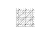
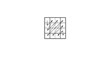
- the figure which shows the example of the quantization matrix used in embodiment The figure which shows the scanning method of the element of the quantization matrix used in embodiment.
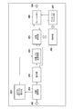
- FIG. 1 is a block composition of the image coding device of the present embodiment.
- the image coding device has a control unit 150 that controls the entire device.
- the control unit 150 includes a CPU, a ROM for storing a program executed by the CPU, and a RAM used as a work area of the CPU.
- the image coding device includes an input terminal 101, a block division unit 102, a quantization matrix holding unit 103, a prediction unit 104, a conversion / quantization unit 105, an inverse quantization / inverse conversion unit 106, an image reproduction unit 107, and a frame. It has a memory 108, an in-loop filter unit 109, a coding unit 110, an integrated coding unit 111, an output terminal 112, and a quantization matrix coding unit 113.
- the input terminal 101 inputs the image data to be encoded generated by the image data source in frame units.
- the image data generation source may be of any type, such as an image pickup device, a file server that stores image data to be encoded, a storage medium, and the like.
- the output terminal 112 outputs the coded data to the output destination device, and the output destination device is not particularly limited to a storage medium, a file server, or the like.
- the block division unit 102 divides the image of the input frame into a plurality of basic blocks, and outputs one of the basic blocks to the prediction unit 104 in the subsequent stage in order.
- the quantization matrix holding unit 103 generates a plurality of quantization matrices prior to coding and holds them in an internal memory (not shown).
- the method of generating the quantization matrix is not particularly limited, but the user may input the quantization matrix, calculate from the characteristics of the input image, or use a predetermined value as an initial value. ..
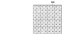
- the quantization matrix holding unit 103 in the present embodiment corresponds to the two-dimensional quantization matrix 800 corresponding to the orthogonal conversion of 8 ⁇ 8 pixels shown in FIG. 8A and the 4 ⁇ 4 orthogonal conversion shown in FIGS. 8B and 8C.
- the two-dimensional quantization matrices 801 and 802 are generated and held.
- the quantization matrix 800 is for the luminance component
- the quantization matrices 801 and 802 are for the two color difference components.
- the prediction unit 104 determines sub-block division for the image data in the basic block unit, performs intra-frame prediction such as intra-frame prediction and inter-frame prediction in the sub-block unit, and generates prediction image data. .. Further, the prediction unit 104 calculates and outputs a prediction error for each pixel from the input image data and the predicted image data. Further, the prediction unit 104 also outputs information necessary for prediction, for example, information such as sub-block division, prediction mode, motion vector, and the like together with the prediction error. Hereinafter, the information necessary for this prediction will be referred to as prediction information.
- the conversion / quantization unit 105 orthogonally converts the prediction error input from the prediction unit 104 in subblock units to obtain an orthogonal conversion coefficient (orthogonally converted residual coefficient). Further, the conversion / quantization unit 105 uses the quantization matrix stored in the quantization matrix holding unit 103 to quantize the orthogonal conversion coefficient, and the quantized residual coefficient (quantized orthogonality). Conversion factor) is obtained.
- the inverse quantization / inverse conversion unit 106 inputs the residual coefficient from the conversion / quantization unit 105, inversely quantizes it using the quantization matrix stored in the quantization matrix holding unit 103, and reproduces the orthogonal conversion coefficient. To do.
- the inverse quantization / inverse conversion unit 106 further performs inverse orthogonal conversion to reproduce the prediction error.
- the image reproduction unit 107 generates predicted image data by appropriately referring to the frame memory 108 based on the prediction information output from the prediction unit 104.
- the image reproduction unit 107 generates the reproduction image data by adding the prediction error from the inverse quantization / inverse conversion unit 106 to the predicted image data, and stores the reproduced image data in the frame memory 108.
- the in-loop filter unit 109 performs in-loop filter processing such as a deblocking filter and a sample adaptive offset on the reproduced image stored in the frame memory 108, and stores the filtered image data in the frame memory 108 again. ..
- the coding unit 110 encodes the residual coefficient output from the conversion / quantization unit 105 and the prediction information output from the prediction unit 104, generates code data, and outputs the code data to the integrated coding unit 111.
- the quantization matrix coding unit 113 encodes the quantization matrix held in the quantization matrix holding unit 103, generates the quantization matrix code data, and outputs the quantization matrix code data to the integrated coding unit 111.
- the integrated coding unit 111 generates header code data including the quantization matrix code data from the quantization matrix coding unit 113. Then, the integrated coding unit 111 causes the header code data to be followed by the code data output from the coding unit 110 to form a bit stream. Then, the integrated coding unit 111 outputs the formed bit stream via the output terminal 112.
- the image coding operation in the image coding device will be described in more detail below.
- the moving image data in the 4: 2: 0 color format is input in frame units from the input terminal 101, but the still image data for one frame may be input.
- the intra-predictive coding process will be described for ease of explanation, but the present embodiment is not limited to this and can be applied to the inter-predictive coding process.
- the block division unit 101 will be described as dividing the image data input from the input terminal into basic blocks of 8 ⁇ 8 pixels.
- the 8 ⁇ 8 pixel basic block includes pixels having a luminance (Y) component of 8 ⁇ 8 pixels and a color difference (Cb and Cr) component of 4 ⁇ 4 pixels. It should be noted that this is for facilitating understanding, and is not limited to the above numerical values (size).
- a quantization matrix Prior to image coding, a quantization matrix is generated and coded.
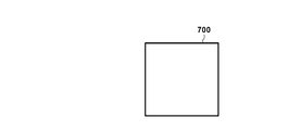
- the quantization matrix holding unit 103 first generates and holds a quantization matrix. Specifically, a quantization matrix is generated according to the size of the encoded subblock and the type of prediction method. In this embodiment, a quantization matrix corresponding to the 8 ⁇ 8 pixel basic block shown in FIG. 7A, which is not divided into subblocks, is generated. That is, the quantization matrix holding unit 103 generates an 8 ⁇ 8 quantization matrix for the luminance (Y) component and a 4 ⁇ 4 quantization matrix for the color difference (Cb and Cr) components.
- the generated quantization matrix is not limited to this, and a quantization matrix corresponding to the shape of the subblock, such as 4 ⁇ 8 or 8 ⁇ 4, may be generated.
- the method for determining each element constituting the quantization matrix is not particularly limited. For example, a predetermined initial value may be used, or may be set individually. Further, it may be generated according to the characteristics of the image.
- the quantization matrix holding unit 103 holds the quantization matrix generated in this way in an internal memory (not shown).
- FIG. 8A shows the quantization matrix 800 for the Y component.
- FIG. 8B shows a quantization matrix 801 for the Cb component
- FIG. 8C shows a quantization matrix 802 for the Cr component.
- the configuration is 8 ⁇ 8 64 pixels and 4 ⁇ 4 16 pixels, and each square in the thick frame represents each element constituting the quantization matrix. ..
- the three types of quantization matrices shown in FIGS. 8A to 8C are held in a two-dimensional shape, but each element in the quantization matrix is of course not limited to this.
- the quantization matrix coding unit 113 reads out the two-dimensional shape quantization matrix held in the quantization matrix holding unit 106 in order, scans each element, calculates the difference between the previous and next elements, and one-dimensionally. Place in the matrix of.
- the scanning method shown in FIGS. 9A or 9B is used according to the size of each of the quantization matrices 800 to 802 shown in FIGS. 8A to 8C, and each element is connected to the immediately preceding element in the scanning order.
- the difference shall be calculated.
- the quantization matrix 802 for 4 ⁇ 4 pixels shown in FIG. 8C is scanned by the scanning method shown in FIG. 9B, but the element located immediately below the first element 8 located in the upper left.
- the difference +6 is calculated. Further, in the coding of the first element (8 in the present embodiment) of the quantization matrix, the difference from a predetermined initial value (for example, 8) is calculated, but of course, the difference is not limited to this, and is arbitrary. The difference from the value or the value of the first element itself may be used. In short, it suffices if the initial value is the same as that of the decoding device.
- a predetermined initial value for example, 8
- the quantization matrix coding unit 113 generates a difference matrix for the quantization matrix 800 of FIG. 8A by using the scanning method of FIG. 9A.
- the quantization matrix coding unit 113 generates a difference matrix for the quantization matrices 801 and 802 of FIGS. 8B and 8C by using the scanning method of FIG. 9B.
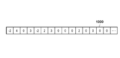
- FIG. 10A shows the difference matrix 1000 obtained from the quantization matrix 800 of FIG. 8A.
- FIG. 10B shows the difference matrix 1001 obtained from the quantization matrix 801 of FIG. 8B.
- FIG. 10C shows the difference matrix 1002 obtained from the quantization matrix 802.
- the quantization matrix coding unit 113 further encodes each difference matrix generated as described above to generate the quantization matrix code data.
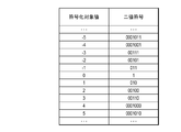
- the quantization matrix coding unit 113 of the present embodiment encodes each element of the difference matrix by assigning a code word using the coding table shown in FIG. 11A, and generates the quantization matrix code data. To do.
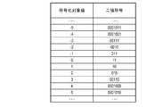
- the coding table is not limited to this, and for example, the coding table shown in FIG. 11B may be used. In this way, the quantization matrix coding unit 113 outputs the generated quantization matrix code data to the integrated coding unit 111 in the subsequent stage.
- the integrated coding unit 111 integrates the code data of the quantization matrix into the header information necessary for encoding the image data.
- the image data is encoded.
- the image data for one frame input from the input terminal 101 is supplied to the block dividing unit 102.
- the block division unit 102 divides the input one-frame image data into a plurality of basic blocks, and outputs the image data in basic block units to the prediction unit 104.
- image data in basic block units of 8 ⁇ 8 pixels is supplied to the prediction unit 104.
- the prediction unit 104 executes prediction processing on the image data in basic block units input from the block division unit 102. Specifically, the subblock division that divides the basic block into smaller subblocks is determined, and the intra prediction mode such as horizontal prediction or vertical prediction is further determined for each subblock.
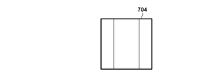
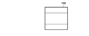
- FIGS. 7A to 7F The sub-block division method will be described with reference to FIGS. 7A to 7F.
- the thick frames of blocks 700 to 705 in FIGS. 7A to 7F have the same size of 8 ⁇ 8 pixels as the basic block.
- Each rectangle in the thick frame represents a subblock.
- FIG. 7B shows an example of the conventional square subblock division, in which the 8 ⁇ 8 pixel basic block 701 is divided into four 4 ⁇ 4 pixel subblocks.
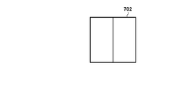
- FIGS. 7C to 7F show an example of rectangular subblock division.
- FIG. 7C shows that the basic block 702 is divided into two sub-blocks (longitudinal in the vertical direction) having a size of 4 ⁇ 8 pixels.
- FIG. 7C shows that the basic block 702 is divided into two sub-blocks (longitudinal in the vertical direction) having a size of 4 ⁇ 8 pixels.
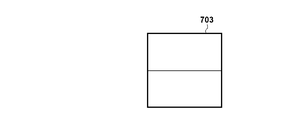
- FIGS. 7E and 7F shows that the basic block 703 is divided into two subblocks (horizontally longitudinal) having a size of 8 ⁇ 4 pixels.
- the basic blocks 704 and 705 of FIGS. 7E and 7F although the division directions are different, they are divided into three rectangular subblocks at a ratio of 1: 2: 1. In this way, not only squares but also rectangular sub-blocks are used for encoding processing.
- FIG. 7A in which the basic block having an 8 ⁇ 8 pixel size is not divided into sub-blocks, is used, but the sub-block division method is not limited to this.
- a quadtree division as shown in FIG. 7B, a ternary division as shown in FIGS. 7E and 7F, or a binary tree division as shown in FIGS. 7C and 7D may be used.
- the sub-block division other than FIG. 7A is also used, the quantization matrix corresponding to the sub-block used in the quantization matrix holding unit 103 is generated. Further, the generated quantization matrix will be encoded by the quantization matrix coding unit 113.
- the prediction unit 104 generates prediction image data from the determined prediction mode and the encoded area stored in the frame memory 108, and further predicts an error in pixel units from the input image data and the prediction image data. Is calculated, and the prediction error is output to the conversion / quantization unit 105. Further, the prediction unit 104 outputs information such as subblock division and prediction mode as prediction information to the coding unit 110 and the image reproduction unit 107.
- the conversion / quantization unit 105 performs orthogonal conversion / quantization on the prediction error input from the prediction unit 104 and generates a residual coefficient. Further, in parallel with this, the conversion / quantization unit 105 determines whether or not to use the color difference residual coefficient integrated coding that collectively encodes the residual coefficients of the components Cb and Cr.
- the color difference residual coefficient integrated coding is to encode only one residual coefficient when the correlation between the residual coefficients of Cb and Cr is high, and omit the coding of the other residual coefficient. The amount is reduced and the coding efficiency is improved.
- On the decoding side only one of the encoded color difference residual coefficients is decoded, and the other color difference residual coefficient is reproduced by calculating using the decoded color difference residual coefficient.
- color difference residual coefficient integrated coding is used, and only the component Cb is used in the subsequent coding section 110. Is encoded, and the coding of the residual coefficient of Cr is omitted.
- the conversion / quantization unit 105 first performs an orthogonal conversion process corresponding to the size of the subblock on the prediction error to generate an orthogonal conversion coefficient (orthogonally converted residual coefficient). Next, the conversion / quantization unit 105 determines whether or not to use the color difference residual coefficient integrated coding from the correlation of the orthogonal conversion coefficients of the generated components Cb and Cr. That is, the conversion / quantization unit 105 determines whether or not the product of the orthogonal conversion coefficient of the component Cb multiplied by (-1) is close to the orthogonal conversion coefficient of the component Cr, and if it is determined to be close, the conversion / quantization unit 105 determines whether or not it is close.
- the conversion / quantization unit 105 It is decided to use the color difference residual coefficient integrated coding. Further, the conversion / quantization unit 105 generates information (1 bit is sufficient) indicating whether or not to use the color difference residual coefficient integrated coding as the color difference integrated information. Then, the conversion / quantization unit 105 quantizes the orthogonal conversion coefficient according to the color component using the quantization matrix stored in the quantization matrix holding unit 103, and the residual coefficient (quantized orthogonal conversion coefficient). ) Is generated. In the present embodiment, it is assumed that the quantization matrix of FIG. 8A is used for the orthogonal conversion coefficient of the Y component, FIG. 8B is used for the orthogonal conversion coefficient of the Cb component, and FIG. 8C is used for the orthogonal conversion coefficient of the Cr component.
- the quantization matrix used is not limited to this. If it is decided to use the color difference residual coefficient integrated coding, the orthogonal conversion coefficient of the Cb component is quantized using the quantization matrix of FIG. 8B, and the quantization processing of the orthogonal conversion coefficient of the Cr component is performed and the subsequent stage is performed. Output is omitted. As a result, it is possible to reduce the amount of calculation for the quantization processing of the Cr component that is not used in the subsequent processing.
- the generated residual coefficient and color difference integrated information are output to the coding unit 110 and the inverse quantization / inverse conversion unit 106.
- the inverse quantization / inverse conversion unit 106 uses the quantization matrix stored in the quantization matrix holding unit 103 for the residual coefficient (quantized orthogonal conversion coefficient) input from the conversion / quantization unit 105. By inverse quantization, the orthogonal conversion coefficient (to be exact, the residual coefficient that is not quantized but is orthogonally converted) is reproduced. The inverse quantization / inverse conversion unit 106 further performs inverse orthogonal conversion of the reproduced orthogonal conversion coefficient to reproduce the prediction error. Similar to the conversion / quantization unit 105, the inverse quantization process uses a quantization matrix corresponding to the color component of the subblock to be encoded.
- the inverse quantization / inverse conversion unit 106 uses the same one as the quantization matrix used in the conversion / quantization unit 105 to perform inverse quantization. That is, the quantization matrix of FIG. 8A is used for the residual coefficient of the Y component, FIG. 8B is used for the residual coefficient of the Cb component, and FIG. 8C is used for the residual coefficient of the Cr component.
- the inverse quantization / inverse conversion unit 106 determines the quantum of the residual coefficient of the Cb component in FIG. 8B. Inverse quantization is performed using the conversion matrix 801 to regenerate the orthogonal conversion coefficient of the Cb component. The inverse quantization / inverse conversion unit 106 reproduces the regenerated Cb component by multiplying the orthogonal conversion coefficient by “-1” as the Cr component orthogonal conversion coefficient. The prediction error reproduced by applying the inverse orthogonal conversion to the orthogonal conversion coefficient reproduced in this way is output to the image reproduction unit 107.
- the image reproduction unit 107 appropriately refers to the frame memory 108 based on the prediction information input from the prediction unit 104, and reproduces the predicted image. Then, the image reproduction unit 107 generates the reproduced image data based on the reproduced predicted image and the prediction error reproduced by the inverse quantization / inverse conversion unit 106, and stores the reproduced image data in the frame memory 108.
- the in-loop filter unit 109 reads the reproduced image data from the frame memory 108 and performs in-loop filter processing such as a deblocking filter. Then, the in-loop filter unit 109 re-stores the filtered image data in the frame memory 108.
- the coding unit 110 entropy-encodes the residual coefficient and color difference integrated information of the sub-block unit generated by the conversion / quantization unit 105, and the prediction information input from the prediction unit 104, and generates code data.
- the coding unit 110 encodes the residual coefficients of all the color components of Y, Cb, and Cr.
- the coding unit 110 encodes the residual coefficients of the color components of Y and Cb, and the residual of the Cr component. Do not encode the coefficients.
- the method of entropy coding is not particularly specified, but Golomb coding, arithmetic coding, Huffman coding and the like can be used.
- the coding unit 110 outputs the generated code data to the integrated coding unit 111.
- the integrated coding unit 111 forms a bit stream by multiplexing the code data and the like input from the coding unit 110 together with the code data of the header described above. Then, the integrated coding unit 111 outputs the formed bit stream from the output terminal 112 to the outside (the recording medium is a network or the like).
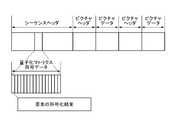
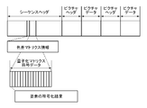
- FIG. 6A is an example of the data structure of the bit stream output in this embodiment.
- the sequence header contains the code data of the quantization matrix and is composed of the coded results of each element.
- the encoded position is not limited to this, and of course, a configuration in which the image header portion and other header portions are encoded may be used.
- the quantization matrix when the quantization matrix is changed in one sequence, it can be updated by newly encoding the quantization matrix. At this time, all the quantization matrices may be rewritten, or some of them may be changed by designating the color components of the quantization matrix corresponding to the quantization matrix to be rewritten.
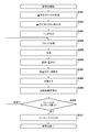
- FIG. 3 is a flowchart showing the coding process for one frame of the control unit 150 in the image coding device of the embodiment.
- the control unit 150 controls the quantization matrix holding unit 103 to generate and hold a two-dimensional quantization matrix.
- the quantization matrix holding unit 103 of the present embodiment corresponds to a block of 8 ⁇ 8 pixels, and the quantization matrix 800 to corresponds to each color component of the Y component, the Cb component, and the Cr component shown in FIGS. 8A to 8C. 802 will be generated and retained.
- the control unit 150 controls the quantization matrix coding unit 113, scans the quantization matrix generated and held in S301, calculates the difference between each element, and generates the difference matrix.
- the quantization matrices 800 to 802 shown in FIGS. 8A to 8C use the scanning method of FIGS. 9A or 9B to generate the difference matrices 1001 to 1003 shown in FIGS. 10A to 10C. Become. Then, the control unit 150 controls the quantization matrix coding unit 113 to encode the generated difference matrix and generate the quantization matrix code data.
- control unit 150 controls the integrated coding unit 111 to encode and output the header information necessary for coding the image data together with the generated quantization matrix code data.
- control unit 150 controls the block division unit 102 to divide the input image in frame units into basic block units.
- control unit 150 controls the prediction unit 104 to execute prediction processing on the image data of the basic block unit generated in S304, and predictive information such as sub-block division information and prediction mode and Generate predicted image data. Further, the control unit 150 controls the prediction unit 104 to calculate the prediction error from the input image data and the prediction image data.
- the control unit 150 controls the conversion / quantization unit 105 to perform orthogonal conversion on the prediction error calculated in S305, and generate a conversion coefficient. Further, the control unit 150 controls the conversion / quantization unit 105 to perform quantization using the quantization matrix generated / held in S301 to generate a residual coefficient. In parallel with this, the conversion / quantization unit 105 causes the conversion / quantization unit 105 to determine whether or not to use the color difference residual coefficient integrated coding that collectively encodes the residual coefficients of Cb and Cr. In the present embodiment, it is assumed that the quantization matrix of FIG. 8A is used for the orthogonal conversion coefficient of the Y component, FIG. 8B is used for the orthogonal conversion coefficient of the Cb component, and FIG.
- the orthogonal conversion coefficient of the Cb component is quantized using the quantization matrix of FIG. 8B, and the quantization process of the orthogonal conversion coefficient of the Cr component is omitted.
- the orthogonal conversion coefficients of the components Cb and Cr are 4 ⁇ 4, respectively.
- represents the absolute value of the real number x.
- the number of coefficients of the color difference component is 4 ⁇ 4, so when the following equation is satisfied using a predetermined threshold value Th, the component is obtained by multiplying the orthogonal conversion coefficient of the component Cb by (-1). It may be judged that it is close to the orthogonal conversion coefficient of Cr.
- the color difference residual coefficient integrated coding when a negative correlation is observed between the residual coefficient of Cb and the residual coefficient of Cr, the color difference residual coefficient integrated coding is used, but this is not the case.
- the determination process for determining whether or not to use the color difference residual coefficient integrated coding is ⁇ ⁇
- the information "a" indicating the correlation may be encoded.
- the control unit 150 controls the inverse quantization / inverse conversion unit 106, and the residual coefficient generated in S306 is inversely quantized using the quantization matrix generated / held in S301. And regenerate the orthogonal transformation coefficient.
- the same quantization matrix used in S306 is used, and the inverse quantization process is performed.
- the residual coefficient of the Cb component is inversely quantized using the quantization matrix of FIG. 8B, and the orthogonal conversion coefficient of the Cb component is reproduced. Further, the reproduced orthogonal conversion coefficient of the Cb component multiplied by "-1" is reproduced as the orthogonal conversion coefficient of the Cr component. Then, the reproduced orthogonal conversion coefficient is inversely orthogonally converted, and the prediction error is reproduced.
- control unit 150 controls the image reproduction unit 107, reproduces the predicted image based on the predicted information generated in S305, and reproduces the image data from the reproduced predicted image and the predicted error generated in S307. And store it in the frame memory 108.
- the control unit 150 controls the coding unit 110 to encode the prediction information generated in S305 and the residual coefficient and color difference integrated information generated in S306 to generate code data.
- the coding unit 110 encodes the residual coefficients of all the color components of Y, Cb, and Cr. To do.
- the coding unit 110 encodes the residual coefficients of the color components of the components Y and Cb, and the residue of the Cr component. The coding of the difference coefficient is omitted.
- the coding unit 110 outputs the generated code data to the integrated coding unit 111.
- the integrated coding unit 111 positions and outputs the coded data from the coding unit 110 so as to follow the previously generated header.
- control unit 150 determines whether or not the coding of all the basic blocks in the frame of interest has been completed. The control unit 150 proceeds to S311 when it determines that the process has ended, returns the process to S304 when it determines that an uncoded basic block remains, and continues encoding for the next basic block. ..
- control unit 150 controls the in-loop filter unit 109, performs in-loop filter processing on the image data reproduced in S308, generates a filtered image, and ends the processing.
- the quantization matrix shown in FIG. 8B is used when the color difference residual coefficient integrated coding is used, but the quantization matrix used is not limited to this.
- the effect does not change even if the quantization / inverse quantization process is performed using the quantization matrix for the Cr component shown in FIG. 8C. It is also possible to generate a new quantization matrix using the existing quantization matrix of FIGS. 8B and 8C and use it for the quantization / inverse quantization process.
- another quantization matrix may be encoded for the color difference residual coefficient integrated coding.
- coding is performed using the quantization matrix 803 for color difference residual coefficient integrated coding, and the color difference residual coefficient integrated coding is performed. It can also be configured to be used for the quantization processing of the subblocks used. As a result, it is possible to realize a unique quantization control for the subblock using the color difference residual coefficient integrated coding.
- the quantization matrix for the subblock using the color difference residual coefficient integrated coding is uniquely determined, but it may be configured to be selectable by introducing an identifier.
- FIG. 6B selectively introduces the color difference matrix information (2 bits) for designating the quantization matrix to selectively select the quantization matrix for the subblock using the color difference residual coefficient integrated coding. It was done.
- FIG. 8B which is a quantization matrix for the Cb component
- FIG. 8C which is a quantization matrix for the Cr component
- FIG. 8D is used for the subblock using the color difference residual coefficient integrated coding.
- the sub-block the basic block
- the conversion coefficient of the component Cb of the subblock is quantized using the quantization matrix 801 shown in FIG. 8B
- the conversion coefficient of the Cr component is quantized using the quantization matrix 802 of FIG. 8C.
- the color difference integration information of a certain subblock of a certain picture is coded by the color difference residual coefficient integration, which of the subblocks of the components Cb and Cr is encoded is a header. It depends on the color difference matrix information stored in. For example, when the color difference matrix information is 0, it is shown that the conversion coefficient of the subblock of the component Cb among the components Cb and Cr is quantized and encoded by the quantization matrix 801 of FIG. 8B, and the quantum of the component Cr is shown. Indicates that quantization and coding are omitted.
- the conversion coefficient of the subblock of the component Cr among the components Cb and Cr is quantized and encoded using the quantization matrix 802 of FIG. 8C. It is shown that the quantization and coding of the component Cb are omitted (the component Cb may be encoded and the component Cr may be omitted).
- the conversion coefficient of the subblock of the component Cb (or the component Cr) among the components Cb and Cr is quantized and encoded using the quantization matrix 803 of FIG. 8D. It is shown that the quantization and coding of the component Cr (or the component Cb) are omitted.
- the coded data of the quantization matrix 803 is stored in the header. That is, the quantization matrix holding unit 103 generates and holds the quantization matrix 803, and the quantization matrix coding unit 113 also encodes the quantization matrix 803.
- FIG. 2 is a block configuration diagram of an image decoding device that decodes the coded image data generated by the image coding device in the embodiment.
- the configuration and its operation related to the decoding process will be described with reference to the figure.
- the image decoding device has a control unit 250 that controls the entire device.
- the control unit 250 has a CPU, a ROM for storing a program executed by the CPU, and a RAM used as a work area of the CPU.
- the image decoding device includes an input terminal 201, a separation decoding unit 202, a decoding unit 203, an inverse quantization / inverse conversion unit 204, an image reproduction unit 205, a frame memory 206, an in-loop filter unit 207, an output terminal 208, and the like. It has a quantization matrix decoding unit 209.
- the input terminal 201 inputs a coded bit stream
- the input source is, for example, a storage medium storing the coded stream, but it may be input from a network, and the type thereof does not matter.
- the separation / decoding unit 202 separates the bitstream into code data related to information related to decoding processing and coefficients, and decodes the code data existing in the header part of the bitstream.
- the separation / decoding unit 202 of the present embodiment separates the quantization matrix code data and outputs it to the quantization matrix decoding unit 209. Further, the separation / decoding unit 202 outputs the code data of the image to the decoding unit 203. That is, the separation / decoding unit 202 performs the reverse operation of the integrated coding unit 111 of FIG.
- the quantization matrix decoding unit 209 reproduces and holds the quantization matrix by decoding the quantization matrix code data supplied from the separation decoding unit 202.
- the decoding unit 203 decodes the code data of the image output from the separation decoding unit 202, and reproduces the residual coefficient, the color difference integrated information, and the prediction information.
- the inverse quantization / inverse conversion unit 204 performs inverse quantization on the residual coefficient using the regenerated quantization matrix, and after the inverse quantization unit.
- the prediction error is reproduced by obtaining the coefficient and further performing the inverse orthogonal transformation.
- the image reproduction unit 205 appropriately refers to the frame memory 206 based on the input prediction information to generate the prediction image data. Then, the image reproduction unit 205 generates the reproduction image data from the predicted image data and the prediction error reproduced by the inverse quantization / inverse conversion unit 204, and stores the reproduced image data in the frame memory 206.
- the in-loop filter unit 207 performs in-loop filter processing such as a deblocking filter on the reproduced image data stored in the frame memory 206, and obtains the image data after the filter processing. Restore in frame memory.
- in-loop filter processing such as a deblocking filter
- the output terminal 208 sequentially outputs the frame images stored in the frame memory 206 to the outside.
- the output destination is generally a display device, but other devices may be used.
- the encoded bit stream is input in frame units.
- the bit stream for one frame input from the input terminal 201 is supplied to the separation / decoding unit 202.
- the separation / decoding unit 202 separates the bitstream into code data related to information related to decoding processing and coefficients, and decodes the code data existing in the header part of the bitstream. Then, the separation / decoding unit 202 supplies the quantization matrix code data included in the header unit to the quantization matrix decoding unit 209, and supplies the code data of the image data to the decoding unit 202.
- the separation / decoding unit 202 first extracts the quantization matrix code data from the sequence header of the bitstream shown in FIG. 6A and outputs it to the quantization matrix decoding unit 209. In this embodiment, the quantization matrix code data corresponding to the quantization matrix shown in FIGS. 8A to 8C is extracted and output. Subsequently, the code data of the basic block unit of the picture data is extracted and output to the decoding unit 203.
- the quantization matrix decoding unit 209 first decodes the input quantization matrix code data, and reproduces the one-dimensional difference matrices 1000 to 1002 shown in FIGS. 10A to 10C. Then, the quantization matrix decoding unit 209 decodes each quantization matrix using the coding table shown in FIG. 11A, similarly to the coding side. In the embodiment, the coded table of FIG. 11A is used, but the coded table of FIG. 11B may be used. In short, the same one as the coding side may be used. The quantization matrix decoding unit 209 reverse-scans the reproduced one-dimensional difference matrices 1000 to 1002, and reproduces and holds the two-dimensional quantization matrix.
- the quantization matrix coding unit 113 of the present embodiment decodes the difference matrices 1000 to 1002 shown in FIGS. 10A to 10C by using the scanning method shown in FIGS. 9A or 9B according to their respective sizes. .. As a result, the quantization matrix coding unit 113 can reproduce and hold the three types of quantization matrices 800 to 802 shown in FIGS. 8A to 8C.
- the decoding unit 203 decodes the code data supplied from the separation decoding unit 202, reproduces the color difference integrated information and the prediction information, and further reproduces the residual coefficient according to the reproduced color difference integrated information.
- the decoding unit 203 reproduces the prediction information and acquires the prediction mode used in the subblock.
- the decoding unit 203 reproduces the color difference integrated information and determines whether or not the color difference residual coefficient integrated coding is performed in the subblock.
- the decoding unit 203 decodes and reproduces the residual coefficients of all the color components of Y, Cb, and Cr.
- the decoding unit 203 decodes the residual coefficient of the color components of Y and Cb (the code of the color component of Cr). Since the converted data does not exist, the decryption process is not performed). The decoding unit 203 outputs the reproduced color difference integrated information and the residual coefficient to the inverse quantization / inverse conversion unit 204, and outputs the reproduced prediction information to the image reproduction unit 205.
- the inverse quantization / inverse conversion unit 204 performs inverse quantization on the input residual coefficient using the quantization matrix reproduced by the quantization matrix decoding unit 209 to generate an orthogonal conversion coefficient, and further reverses. Quantization is performed to reproduce the prediction error.
- the inverse quantization / inverse conversion unit 204 like the inverse quantization / inverse conversion unit 106 on the coding side, performs inverse quantization using a quantization matrix corresponding to the color component of the decoding target subblock. That is, the quantization matrix of FIG. 8A is used for the residual coefficient of the Y component, FIG. 8B is used for the residual coefficient of the Cb component, and FIG. 8C is used for the residual coefficient of the Cr component.
- the decoding unit 203 does not supply the residual coefficient of the orthogonal conversion coefficient of the Cr component. Therefore, the inverse quantization / inverse conversion unit 204 reproduces the orthogonal conversion coefficient of the Cr component after inverse quantization using the quantization matrix of the residual coefficient of the Cb component in FIG. 8B. That is, the efficiency of processing is improved by performing inverse quantization using a quantization matrix before the regeneration of the Cr component. Specifically, the inverse quantization / inverse conversion unit 204 reproduces the reproduced Cb component orthogonal conversion coefficient multiplied by (-1) as the Cr component orthogonal conversion coefficient, and supplies the image reproduction unit 205. To do.
- the prediction error reproduced by applying the inverse orthogonal conversion to the orthogonal conversion coefficient reproduced in this way is output to the image reproduction unit 205.
- the quantization matrix used is not limited to this, and may be the same as the quantization matrix used in the conversion / quantization unit 105 and the inverse quantization / inverse conversion unit 106 on the coding side.
- the image reproduction unit 205 appropriately refers to the frame memory 206 based on the prediction information input from the decoding unit 203, and reproduces the predicted image. Similar to the prediction unit 104 on the coding side, the image reproduction unit 205 of the present embodiment uses intra-prediction such as horizontal prediction and vertical prediction. Since the specific prediction processing is the same as that of the prediction unit 104 on the coding side, the description thereof will be omitted.
- the image reproduction unit 205 reproduces the image data from the predicted image and the prediction error input from the inverse quantization / inverse conversion unit 204, and re-stores the image data in the frame memory 206. The stored image data is used as a reference when making a prediction.
- the in-loop filter unit 207 reads the reproduced image from the frame memory 206 and performs in-loop filter processing such as a deblocking filter. Then, the in-loop filter unit 207 re-stores the filtered image in the frame memory 206.
- the reproduced image stored in the frame memory 206 is finally output from the output terminal 208 to the outside (a display device is a typical example).
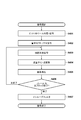
- FIG. 4 is a flowchart showing a decoding process of the control unit 250 in the image decoding device according to the embodiment.
- the control unit 250 controls the separation / decoding unit 202 to separate the bitstream into code data related to decoding processing and coefficients, and decodes the code data of the header portion. More specifically, the separation / decoding unit 202 supplies the quantization matrix code data to the quantization matrix decoding unit 209, and supplies the image code data to the decoding unit 203.
- the control unit 250 controls the quantization matrix decoding unit 209 to decode the quantization matrix code data reproduced in S401.
- the quantization matrix decoding unit 209 reproduces the one-dimensional difference matrices 1000 to 1002 shown in FIGS. 10A to 10C.
- the quantization matrix decoding unit 209 scans the one-dimensional difference matrix 1000 as shown in FIG. 9A, decodes it according to the coding table of FIG. 11A, reproduces and holds the quantization matrix 800 of FIG. 8A. To do.
- the quantization matrix decoding unit 209 scans the one-dimensional difference matrices 1001 and 1102 as shown in FIG. 9B, decodes them according to the coding table of FIG. 11A, and decodes the one-dimensional difference matrices 1001 and 1102 according to the coding table of FIGS. Regenerate and hold 802.
- control unit 250 controls the decoding unit 203, decodes the code data separated in S401, reproduces the color difference integrated information and the prediction information, and uses the residual coefficient of the brightness component and the color difference integrated information.
- the residual coefficient of the corresponding color difference is reproduced. It should be noted that, as described above, the residual coefficient of the color difference to be reproduced may be both Cb and Cr or only Cb.
- the control unit 250 controls the inverse quantization / inverse conversion unit 204, performs inverse quantization on the residual coefficient using the quantization matrix reproduced in S402, and generates an orthogonal conversion coefficient.
- the inverse quantization / inverse conversion unit 204 further performs an inverse orthogonal transformation to reproduce the prediction error.
- the quantization matrix used in the inverse quantization process is determined according to the color component of the subblock to be decoded. That is, the inverse quantization / inverse conversion unit 204 has FIG. 8A for the residual coefficient of the Y component, FIG. 8B for the residual coefficient of the Cb component, and FIG. 8C for the residual coefficient of the Cr component.
- Quantization matrix is used to dequantize.
- the quantization matrix used is not limited to this, and may be the same as the quantization matrix used on the coding side.
- the inverse quantization / inverse conversion unit 204 quantizes the residual coefficient of the Cb component in FIG. 8B.
- the orthogonal conversion coefficient of the Cb component is reproduced by inverse quantization using a matrix.
- the inverse quantization / inverse conversion unit 204 reproduces the regenerated Cb component by multiplying the orthogonal conversion coefficient by (-1) as the Cr component orthogonal conversion coefficient.
- the control unit 250 controls the image reproduction unit 205 to reproduce the image generated in S403. Specifically, the image reproduction unit 205 reproduces the predicted image with reference to the frame memory 206 based on the prediction information. At this time, the image reproduction unit 205 uses intra-prediction such as horizontal prediction and vertical prediction as in S305 on the coding side. Then, the image reproduction unit 205 reproduces the image data from the reproduced predicted image and the prediction error generated in S404, and stores the reproduced image data in the frame memory 206.
- intra-prediction such as horizontal prediction and vertical prediction as in S305 on the coding side.
- control unit 250 determines whether or not the decoding of all the basic blocks in the frame of interest has been completed, and if so, proceeds to S407, and if there are undecrypted blocks, the process proceeds to S407. The process is returned to S403 in order to target the next basic block for decoding.
- control unit 250 controls the in-loop filter unit 207, performs in-loop filter processing on the image data reproduced in S405, generates a filtered image, and ends the processing.
- the coded bitstream generated by the image coding device described above that is, the subblock using the color difference residual coefficient integrated coding, can be quantized for each frequency component. It is possible to decode a bit stream that is controlled and has improved subjective image quality.
- the decoding process when the header of the bitstream contains the color difference matrix information will be as follows.
- the color difference integration information of a certain subblock of a certain picture indicates that the color difference residual coefficient integrated coding is not used, the remainder of the component Cb of the subblock.
- the difference coefficient is inversely quantized using the quantization matrix 801 shown in FIG. 8B, and the residual coefficient of the Cr component is inversely quantized using the quantization matrix 802 shown in FIG. 8C.
- the color difference integration information of a certain subblock of a certain picture is coded by the color difference residual coefficient integration, which of the subblocks of the components Cb and Cr is encoded is a header. It depends on the color difference matrix information stored in. The following is the explanation.
- the residual coefficient of the subblock of the component Cb among the components Cb and Cr is inversely quantized by the quantization matrix 801 of FIG. 8B to obtain a conversion coefficient and decoded. Since the component Cr does not exist, a value obtained by multiplying the conversion coefficient of the inverse quantized component Cb by "-1" is generated as the conversion coefficient of the component Cr and decoded.
- the residual coefficient of the subblock of the component Cr among the components Cb and Cr is inversely quantized by the quantization matrix 802 of FIG. 8C to obtain a conversion coefficient and decoded. Since the component Cb does not exist, a value obtained by multiplying the conversion coefficient of the inverse quantized component Cr by "-1" is generated as the conversion coefficient of the component Cb and decoded.
- the residual coefficient of one of the components Cb and Cr (for example, the component Cb) is inversely quantized by the quantization matrix 801 of FIG. 8B to obtain a conversion coefficient. It is decrypted. Since the other component Cr does not exist, a value obtained by multiplying the conversion coefficient of one of the inversely quantized components by "-1" is generated as the conversion coefficient of the other component and decoded.
- FIG. 5 is a block diagram showing a configuration example of computer hardware applicable to the image coding device and the image decoding device according to the above embodiment.
- the CPU 501 controls the entire computer by using the computer programs and data stored in the RAM 502 and the ROM 503, and executes each of the above-described processes as performed by the image processing device according to the above embodiment. That is, the CPU 501 functions as each processing unit shown in FIGS. 1 and 2.
- the RAM 502 has an area for temporarily storing programs and data acquired from the outside via the external storage device 506 and the I / F (interface) 507. Further, the RAM 502 is also used as a work area used by the CPU 501 when executing various processes.
- the RAM 502 can be allocated as a frame memory, for example, or various other areas can be provided as appropriate.
- the ROM 503 stores the setting data of this computer, the boot program, and the like.
- the operation unit 504 is composed of a keyboard, a mouse, and the like, and can be operated by a user of the computer to input various instructions to the CPU 501.
- the display unit 505 displays the processing result by the CPU 501.
- the display unit 505 is composed of, for example, a liquid crystal display.
- the external storage device 506 is a large-capacity information storage device represented by a hard disk drive device.
- the external storage device 506 stores an OS (operating system) and a computer program (application program) for realizing the functions of the respective parts shown in FIGS. 1 and 2 in the CPU 501. Further, each image data as a processing target may be stored in the external storage device 506.
- the computer programs and data stored in the external storage device 506 are appropriately loaded into the RAM 502 according to the control by the CPU 501, and are processed by the CPU 501.
- a network such as a LAN or the Internet, or other devices such as a projection device or a display device can be connected to the I / F 507, and the computer acquires and sends various information via the I / F 507. Can be done.
- Reference numeral 508 is a bus connecting the above-mentioned parts.
- the CPU 501 executes the boot program stored in the ROM 503, loads the OS stored in the external storage device 506 into the RAM 502, and executes the boot program. Then, under the control of the OS, the CPU 501 loads the application program related to encoding or decoding from the external storage device 506 into the RAM 502 and executes it.
- the CPU 501 functions as each processing unit of FIG. 1 or 2, and the present device functions as an image coding device or an image decoding device.
- the present invention supplies a program that realizes one or more functions of the above-described embodiment to a system or device via a network or storage medium, and one or more processors in the computer of the system or device reads and executes the program. It can also be realized by the processing to be performed. It can also be realized by a circuit (for example, ASIC) that realizes one or more functions.
- a circuit for example, ASIC
- the present invention is used in a coding device / decoding device that encodes / decodes still images / moving images.
- it can be applied to a coding method and a decoding method using a quantization matrix.
Abstract
Priority Applications (10)
| Application Number | Priority Date | Filing Date | Title |
|---|---|---|---|
| CN202080041967.8A CN113994677A (zh) | 2019-06-07 | 2020-04-02 | 图像编码装置、图像解码装置、方法和程序 |
| EP20819205.4A EP3982632A4 (fr) | 2019-06-07 | 2020-04-02 | Dispositif de codage d'image, dispositif de décodage d'image, procédé, et programme |
| KR1020217041995A KR20220011175A (ko) | 2019-06-07 | 2020-04-02 | 화상 복호 장치, 복호 방법, 및 컴퓨터 프로그램 |
| BR112021024187A BR112021024187A2 (pt) | 2019-06-07 | 2020-04-02 | Dispositivo de codificação de imagem, dispositivo de decodificação de imagem, método e programa |
| US17/542,254 US11856198B2 (en) | 2019-06-07 | 2021-12-03 | Image decoding device, method, and non-transitory computer-readable storage medium |
| US18/510,126 US20240089440A1 (en) | 2019-06-07 | 2023-11-15 | Image decoding device, method, and non-transitory computer-readable storage medium |
| US18/510,096 US20240089439A1 (en) | 2019-06-07 | 2023-11-15 | Image decoding device, method, and non-transitory computer-readable storage medium |
| US18/510,167 US20240089442A1 (en) | 2019-06-07 | 2023-11-15 | Image decoding device, method, and non-transitory computer-readable storage medium |
| US18/510,148 US20240089441A1 (en) | 2019-06-07 | 2023-11-15 | Image decoding device, method, and non-transitory computer-readable storage medium |
| US18/510,344 US20240089443A1 (en) | 2019-06-07 | 2023-11-15 | Image decoding device, method, and non-transitory computer-readable storage medium |
Applications Claiming Priority (2)
| Application Number | Priority Date | Filing Date | Title |
|---|---|---|---|
| JP2019107454A JP2020202473A (ja) | 2019-06-07 | 2019-06-07 | 画像符号化装置及び画像復号装置及び方法及びプログラム |
| JP2019-107454 | 2019-06-07 |
Related Child Applications (1)
| Application Number | Title | Priority Date | Filing Date |
|---|---|---|---|
| US17/542,254 Continuation US11856198B2 (en) | 2019-06-07 | 2021-12-03 | Image decoding device, method, and non-transitory computer-readable storage medium |
Publications (1)
| Publication Number | Publication Date |
|---|---|
| WO2020246125A1 true WO2020246125A1 (fr) | 2020-12-10 |
Family
ID=73652489
Family Applications (1)
| Application Number | Title | Priority Date | Filing Date |
|---|---|---|---|
| PCT/JP2020/015216 WO2020246125A1 (fr) | 2019-06-07 | 2020-04-02 | Dispositif de codage d'image, dispositif de décodage d'image, procédé, et programme |
Country Status (8)
| Country | Link |
|---|---|
| US (6) | US11856198B2 (fr) |
| EP (1) | EP3982632A4 (fr) |
| JP (2) | JP2020202473A (fr) |
| KR (1) | KR20220011175A (fr) |
| CN (1) | CN113994677A (fr) |
| BR (1) | BR112021024187A2 (fr) |
| TW (1) | TW202101990A (fr) |
| WO (1) | WO2020246125A1 (fr) |
Families Citing this family (1)
| Publication number | Priority date | Publication date | Assignee | Title |
|---|---|---|---|---|
| US11641469B2 (en) * | 2020-01-13 | 2023-05-02 | Qualcomm Incorporated | Signaling scaling matrices in video coding |
Citations (3)
| Publication number | Priority date | Publication date | Assignee | Title |
|---|---|---|---|---|
| WO2011052215A1 (fr) * | 2009-10-30 | 2011-05-05 | パナソニック株式会社 | Procédé de décodage, appareil décodeur, procédé de codage et appareil codeur |
| JP2013038758A (ja) | 2011-07-13 | 2013-02-21 | Canon Inc | 画像符号化装置、画像符号化方法及びプログラム、画像復号装置、画像復号方法及びプログラム |
| JP2019107454A (ja) | 2018-12-28 | 2019-07-04 | 日本光電工業株式会社 | 医療用システム |
Family Cites Families (6)
| Publication number | Priority date | Publication date | Assignee | Title |
|---|---|---|---|---|
| JP5026092B2 (ja) * | 2007-01-12 | 2012-09-12 | 三菱電機株式会社 | 動画像復号装置および動画像復号方法 |
| JPWO2010070897A1 (ja) * | 2008-12-16 | 2012-05-24 | パナソニック株式会社 | 動画像符号化方法、動画像復号方法、動画像符号化装置、動画像復号装置、プログラム、及び集積回路 |
| CN102164284A (zh) * | 2010-02-24 | 2011-08-24 | 富士通株式会社 | 视频解码方法和系统 |
| JP2011259205A (ja) * | 2010-06-09 | 2011-12-22 | Sony Corp | 画像復号化装置と画像符号化装置およびその方法とプログラム |
| JP6210368B2 (ja) * | 2012-09-18 | 2017-10-11 | サン パテント トラスト | 画像復号方法および画像復号装置 |
| CN107360419B (zh) * | 2017-07-18 | 2019-09-24 | 成都图必优科技有限公司 | 一种基于透视模型的运动前视视频帧间预测编码方法 |
-
2019
- 2019-06-07 JP JP2019107454A patent/JP2020202473A/ja active Pending
-
2020
- 2020-04-02 CN CN202080041967.8A patent/CN113994677A/zh active Pending
- 2020-04-02 WO PCT/JP2020/015216 patent/WO2020246125A1/fr active Application Filing
- 2020-04-02 BR BR112021024187A patent/BR112021024187A2/pt unknown
- 2020-04-02 KR KR1020217041995A patent/KR20220011175A/ko active Search and Examination
- 2020-04-02 EP EP20819205.4A patent/EP3982632A4/fr active Pending
- 2020-04-27 TW TW109113992A patent/TW202101990A/zh unknown
-
2021
- 2021-12-03 US US17/542,254 patent/US11856198B2/en active Active
-
2023
- 2023-11-15 US US18/510,148 patent/US20240089441A1/en active Pending
- 2023-11-15 US US18/510,167 patent/US20240089442A1/en active Pending
- 2023-11-15 US US18/510,126 patent/US20240089440A1/en active Pending
- 2023-11-15 US US18/510,096 patent/US20240089439A1/en active Pending
- 2023-11-15 US US18/510,344 patent/US20240089443A1/en active Pending
- 2023-12-04 JP JP2023204899A patent/JP2024015184A/ja active Pending
Patent Citations (3)
| Publication number | Priority date | Publication date | Assignee | Title |
|---|---|---|---|---|
| WO2011052215A1 (fr) * | 2009-10-30 | 2011-05-05 | パナソニック株式会社 | Procédé de décodage, appareil décodeur, procédé de codage et appareil codeur |
| JP2013038758A (ja) | 2011-07-13 | 2013-02-21 | Canon Inc | 画像符号化装置、画像符号化方法及びプログラム、画像復号装置、画像復号方法及びプログラム |
| JP2019107454A (ja) | 2018-12-28 | 2019-07-04 | 日本光電工業株式会社 | 医療用システム |
Non-Patent Citations (4)
| Title |
|---|
| CHUBACH, OLENA ET AL.: "CE7-related: Support of quantization matrices for VVC", JOINT VIDEO EXPERTS TEAM (JVET), 25 March 2019 (2019-03-25), XP030204823 * |
| HELMRICH, CHRISTIAN ET AL.: "CE7-related: Joint chroma residual coding with multiple modes", JOINT VIDEO EXPERTS TEAM (JVET, 21 March 2019 (2019-03-21), XP030204159 * |
| LAINEMA, JANI: "CE7: Joint coding of chrominance residuals (CE7-1)", JOINT VIDEO EXPERTS TEAM (JVET, 12 March 2019 (2019-03-12), XP030202618 * |
| See also references of EP3982632A4 |
Also Published As
| Publication number | Publication date |
|---|---|
| US20240089439A1 (en) | 2024-03-14 |
| EP3982632A1 (fr) | 2022-04-13 |
| US20220094937A1 (en) | 2022-03-24 |
| BR112021024187A2 (pt) | 2022-01-11 |
| US20240089443A1 (en) | 2024-03-14 |
| TW202101990A (zh) | 2021-01-01 |
| US11856198B2 (en) | 2023-12-26 |
| US20240089441A1 (en) | 2024-03-14 |
| JP2020202473A (ja) | 2020-12-17 |
| US20240089440A1 (en) | 2024-03-14 |
| KR20220011175A (ko) | 2022-01-27 |
| EP3982632A4 (fr) | 2023-05-03 |
| US20240089442A1 (en) | 2024-03-14 |
| JP2024015184A (ja) | 2024-02-01 |
| CN113994677A (zh) | 2022-01-28 |
Similar Documents
| Publication | Publication Date | Title |
|---|---|---|
| JP2024015184A (ja) | 画像復号装置及び方法及びプログラム | |
| WO2020184229A1 (fr) | Dispositif de codage d'image, procédé de codage d'image, et programme | |
| JP2023164601A (ja) | 画像符号化装置、画像符号化方法、及びプログラム、画像復号装置、画像復号方法、及びプログラム | |
| WO2020003740A1 (fr) | Dispositif de codage d'image, dispositif de décodage d'image, procédés de commande et programme correspondants | |
| WO2021054012A1 (fr) | Dispositif de codage d'image, dispositif de décodage d'image, procédé de commande associé, et programme | |
| WO2021187023A1 (fr) | Dispositif de codage d'image, procédé et programme de codage d'image, dispositif de décodage d'image, et procédé et programme de décodage d'image | |
| RU2765428C1 (ru) | Устройство кодирования изображений, устройство декодирования изображений, способы управления ими и программа | |
| WO2020255820A1 (fr) | Dispositif de codage d'image, dispositif de décodage d'image, et programme d'ordinateur | |
| JP7358136B2 (ja) | 画像符号化装置、画像符号化方法、及びプログラム、画像復号装置、画像復号方法、及びプログラム | |
| WO2020183859A1 (fr) | Dispositif de codage d'image, dispositif de décodage d'image, procédé de codage d'image, procédé de décodage d'image, et programme | |
| WO2020184223A1 (fr) | Décodeur d'image, procédé de décodage d'image, et programme | |
| WO2020184227A1 (fr) | Décodeur d'image, procédé de décodage d'image et programme | |
| JP2021150723A (ja) | 画像符号化装置、画像符号化方法、及びプログラム、画像復号装置、画像復号方法、及びプログラム | |
| WO2020129489A1 (fr) | Dispositif de codage d'image, dispositif de décodage d'image, et procédé et programme pour les commander | |
| CN118018737A (en) | Image encoding apparatus, image decoding apparatus, and control method | |
| CN118018736A (en) | Image encoding apparatus, image decoding apparatus, and control method | |
| CN118018733A (en) | Image encoding apparatus, image decoding apparatus, and control method | |
| CN118018735A (en) | Image encoding apparatus, image decoding apparatus, and control method | |
| CN118018734A (en) | Image encoding apparatus, image decoding apparatus, and control method |
Legal Events
| Date | Code | Title | Description |
|---|---|---|---|
| 121 | Ep: the epo has been informed by wipo that ep was designated in this application |
Ref document number: 20819205 Country of ref document: EP Kind code of ref document: A1 |
|
| WWE | Wipo information: entry into national phase |
Ref document number: 122023005968 Country of ref document: BR |
|
| REG | Reference to national code |
Ref country code: BR Ref legal event code: B01A Ref document number: 112021024187 Country of ref document: BR |
|
| NENP | Non-entry into the national phase |
Ref country code: DE |
|
| ENP | Entry into the national phase |
Ref document number: 20217041995 Country of ref document: KR Kind code of ref document: A |
|
| WWE | Wipo information: entry into national phase |
Ref document number: 2020819205 Country of ref document: EP |
|
| ENP | Entry into the national phase |
Ref document number: 112021024187 Country of ref document: BR Kind code of ref document: A2 Effective date: 20211130 |