WO2020242260A1 - Procédé et dispositif de compression d'image basée sur l'apprentissage machine utilisant un contexte global - Google Patents
Procédé et dispositif de compression d'image basée sur l'apprentissage machine utilisant un contexte global Download PDFInfo
- Publication number
- WO2020242260A1 WO2020242260A1 PCT/KR2020/007039 KR2020007039W WO2020242260A1 WO 2020242260 A1 WO2020242260 A1 WO 2020242260A1 KR 2020007039 W KR2020007039 W KR 2020007039W WO 2020242260 A1 WO2020242260 A1 WO 2020242260A1
- Authority
- WO
- WIPO (PCT)
- Prior art keywords
- image
- entropy
- context
- padding
- model
- Prior art date
Links
- 238000000034 method Methods 0.000 title claims abstract description 90
- 238000007906 compression Methods 0.000 title claims abstract description 83
- 230000006835 compression Effects 0.000 title claims abstract description 83
- 238000010801 machine learning Methods 0.000 title abstract description 6
- 238000012545 processing Methods 0.000 claims description 70
- 238000004891 communication Methods 0.000 claims description 13
- 239000000203 mixture Substances 0.000 claims description 9
- 238000009826 distribution Methods 0.000 description 56
- 230000006870 function Effects 0.000 description 45
- 238000013459 approach Methods 0.000 description 41
- 238000003860 storage Methods 0.000 description 23
- 238000012549 training Methods 0.000 description 20
- 230000006872 improvement Effects 0.000 description 17
- 238000005457 optimization Methods 0.000 description 15
- 230000008569 process Effects 0.000 description 14
- 230000009466 transformation Effects 0.000 description 13
- 238000013139 quantization Methods 0.000 description 8
- 238000013528 artificial neural network Methods 0.000 description 7
- 238000010606 normalization Methods 0.000 description 7
- 238000000605 extraction Methods 0.000 description 5
- 238000012360 testing method Methods 0.000 description 5
- 230000015572 biosynthetic process Effects 0.000 description 4
- 238000006243 chemical reaction Methods 0.000 description 4
- 238000013527 convolutional neural network Methods 0.000 description 4
- 238000010586 diagram Methods 0.000 description 4
- 239000004615 ingredient Substances 0.000 description 4
- 238000003786 synthesis reaction Methods 0.000 description 4
- 208000037170 Delayed Emergence from Anesthesia Diseases 0.000 description 3
- BQCADISMDOOEFD-UHFFFAOYSA-N Silver Chemical compound [Ag] BQCADISMDOOEFD-UHFFFAOYSA-N 0.000 description 3
- 230000008859 change Effects 0.000 description 3
- 230000000694 effects Effects 0.000 description 3
- 238000003780 insertion Methods 0.000 description 3
- 230000037431 insertion Effects 0.000 description 3
- 210000004185 liver Anatomy 0.000 description 3
- 229910052709 silver Inorganic materials 0.000 description 3
- 239000004332 silver Substances 0.000 description 3
- 230000009471 action Effects 0.000 description 2
- 230000008901 benefit Effects 0.000 description 2
- 238000004364 calculation method Methods 0.000 description 2
- 238000007796 conventional method Methods 0.000 description 2
- 238000009795 derivation Methods 0.000 description 2
- 238000002474 experimental method Methods 0.000 description 2
- 210000000887 face Anatomy 0.000 description 2
- 238000007689 inspection Methods 0.000 description 2
- 230000003993 interaction Effects 0.000 description 2
- 230000011218 segmentation Effects 0.000 description 2
- 239000004065 semiconductor Substances 0.000 description 2
- 238000009827 uniform distribution Methods 0.000 description 2
- 230000004913 activation Effects 0.000 description 1
- 230000003044 adaptive effect Effects 0.000 description 1
- 230000004931 aggregating effect Effects 0.000 description 1
- 230000005540 biological transmission Effects 0.000 description 1
- 230000001364 causal effect Effects 0.000 description 1
- 230000001149 cognitive effect Effects 0.000 description 1
- 238000004590 computer program Methods 0.000 description 1
- 230000007423 decrease Effects 0.000 description 1
- 230000001419 dependent effect Effects 0.000 description 1
- 238000005315 distribution function Methods 0.000 description 1
- 238000009472 formulation Methods 0.000 description 1
- 238000012886 linear function Methods 0.000 description 1
- 238000002156 mixing Methods 0.000 description 1
- 238000012986 modification Methods 0.000 description 1
- 230000004048 modification Effects 0.000 description 1
- 230000003287 optical effect Effects 0.000 description 1
- 238000010422 painting Methods 0.000 description 1
- 238000002360 preparation method Methods 0.000 description 1
- 230000000750 progressive effect Effects 0.000 description 1
- 238000003908 quality control method Methods 0.000 description 1
- 238000011160 research Methods 0.000 description 1
- 230000004044 response Effects 0.000 description 1
- 238000005070 sampling Methods 0.000 description 1
- 230000000007 visual effect Effects 0.000 description 1
Images


Classifications
-
- G—PHYSICS
- G06—COMPUTING; CALCULATING OR COUNTING
- G06T—IMAGE DATA PROCESSING OR GENERATION, IN GENERAL
- G06T9/00—Image coding
- G06T9/002—Image coding using neural networks
-
- H—ELECTRICITY
- H04—ELECTRIC COMMUNICATION TECHNIQUE
- H04N—PICTORIAL COMMUNICATION, e.g. TELEVISION
- H04N19/00—Methods or arrangements for coding, decoding, compressing or decompressing digital video signals
- H04N19/10—Methods or arrangements for coding, decoding, compressing or decompressing digital video signals using adaptive coding
- H04N19/102—Methods or arrangements for coding, decoding, compressing or decompressing digital video signals using adaptive coding characterised by the element, parameter or selection affected or controlled by the adaptive coding
- H04N19/13—Adaptive entropy coding, e.g. adaptive variable length coding [AVLC] or context adaptive binary arithmetic coding [CABAC]
-
- G—PHYSICS
- G06—COMPUTING; CALCULATING OR COUNTING
- G06N—COMPUTING ARRANGEMENTS BASED ON SPECIFIC COMPUTATIONAL MODELS
- G06N20/00—Machine learning
-
- G—PHYSICS
- G06—COMPUTING; CALCULATING OR COUNTING
- G06T—IMAGE DATA PROCESSING OR GENERATION, IN GENERAL
- G06T3/00—Geometric image transformations in the plane of the image
- G06T3/40—Scaling of whole images or parts thereof, e.g. expanding or contracting
- G06T3/4023—Scaling of whole images or parts thereof, e.g. expanding or contracting based on decimating pixels or lines of pixels; based on inserting pixels or lines of pixels
-
- G—PHYSICS
- G06—COMPUTING; CALCULATING OR COUNTING
- G06T—IMAGE DATA PROCESSING OR GENERATION, IN GENERAL
- G06T3/00—Geometric image transformations in the plane of the image
- G06T3/40—Scaling of whole images or parts thereof, e.g. expanding or contracting
- G06T3/4046—Scaling of whole images or parts thereof, e.g. expanding or contracting using neural networks
-
- H—ELECTRICITY
- H04—ELECTRIC COMMUNICATION TECHNIQUE
- H04N—PICTORIAL COMMUNICATION, e.g. TELEVISION
- H04N1/00—Scanning, transmission or reproduction of documents or the like, e.g. facsimile transmission; Details thereof
- H04N1/41—Bandwidth or redundancy reduction
-
- H—ELECTRICITY
- H04—ELECTRIC COMMUNICATION TECHNIQUE
- H04N—PICTORIAL COMMUNICATION, e.g. TELEVISION
- H04N19/00—Methods or arrangements for coding, decoding, compressing or decompressing digital video signals
- H04N19/10—Methods or arrangements for coding, decoding, compressing or decompressing digital video signals using adaptive coding
- H04N19/134—Methods or arrangements for coding, decoding, compressing or decompressing digital video signals using adaptive coding characterised by the element, parameter or criterion affecting or controlling the adaptive coding
- H04N19/136—Incoming video signal characteristics or properties
Definitions
- the following embodiments relate to a video decoding method, a decoding device, an encoding method, and an encoding device.
- a decoding method, a decoding device, an encoding method, and an encoding device that provide image compression based on machine learning using a global context. It is about.
- An embodiment may provide an encoding apparatus, an encoding method, a decoding apparatus, and a decoding method that provide compression for an image based on machine learning using a global context.
- the entropy model may be a context-adaptive entropy model.
- the context-adaptive entropy model can utilize three different types of contexts.
- the above contexts can be used to estimate the parameters of the Gaussian mixture model.
- the parameters may include a weight parameter, an average parameter, and a standard deviation parameter.
- the entropy model may be a context-adaptive entropy model
- the context-adaptive entropy model can use a global context.
- the entropy encoding may be performed by combining an image compression network and a quality enhancement network.
- the quality enhancement network may be a very deep super resolution (VDSR), a residual density network (RDN), or a grouped residual density network (GRDN).
- VDSR very deep super resolution
- RDN residual density network
- GRDN grouped residual density network
- Padding in a horizontal direction or padding in a vertical direction may be applied to the input image.
- the horizontal padding may include inserting one or more rows at the center of the vertical axis of the input image.
- the vertical padding may be the insertion of one or more columns at the center of the horizontal axis of the input image.
- the horizontal padding may be performed when the height of the input image is not a multiple of k.
- the vertical padding may be performed when the width of the input image is not a multiple of k.
- n may be the number of down-scalings for the input image.
- a recording medium for recording the bitstream generated by the encoding method may be provided.
- the communication unit for obtaining a bitstream; And a processor configured to generate a reconstructed image by performing decoding on the bitstream using an entropy model.
- obtaining a bitstream And generating a reconstructed image by performing decoding using an entropy model on the bitstream.
- the entropy model may be a context-adaptive entropy model.
- the context-adaptive entropy model can utilize three different types of contexts.
- the above contexts can be used to estimate the parameters of the Gaussian mixture model.
- the parameters may include a weight parameter, an average parameter, and a standard deviation parameter.
- the entropy model may be a context-adaptive entropy model.
- the context-adaptive entropy model can use a global context.
- the entropy encoding may be performed by combining an image compression network and a quality enhancement network.
- the quality enhancement network may be a very deep super resolution (VDSR), a residual density network (RDN), or a grouped residual density network (GRDN).
- VDSR very deep super resolution
- RDN residual density network
- GRDN grouped residual density network
- a padding area in a horizontal direction or a padding area in a vertical direction may be removed from the reconstructed image.
- the removal of the padding area in the horizontal direction may be the removal of one or more rows from the center on the vertical axis of the reconstructed image.
- the removal of the padding area in the vertical direction may be removing one or more columns from the center on the horizontal axis of the reconstructed image.
- the removal of the padding area in the horizontal direction may be performed when the height of the original image is not a multiple of k.
- the removal of the padding area in the vertical direction may be performed when the width of the original image is not a multiple of k.
- the k may be 2 n .
- N may be the number of down-scalings for the original image.
- An encoding device, an encoding method, a decoding device, and a decoding method are provided that provide compression for an image based on machine learning using a global context.
- FIG. 1 shows an end-to-end image compression based on an entropy model according to an example.
- FIG 3 shows an implementation of an automatic encoder according to an embodiment.
- FIG. 6 illustrates an offset to a current position of (0, 0) according to an example.
- FIG 8 shows an end-to-end joint learning scheme of cascaded image compression and quality improvement according to an embodiment.
- FIG 9 shows an overall network architecture of an image compression network according to an embodiment.
- 10 may show a structure of a model parameter estimator according to an example.
- 11 may show a non-local context processing network according to an example.
- FIG 12 illustrates an offset-context processing network according to an example.
- FIG. 13 shows variables mapped to a global context area according to an example.
- FIG. 14 shows the structure of a GRDN according to an embodiment.
- FIG. 15 shows the structure of a GRDB of GRDN according to an embodiment.
- FIG. 16 shows the structure of an RDB of GRDB according to an embodiment.
- FIG 17 shows an encoder according to an embodiment.
- FIG. 19 is a structural diagram of an encoding apparatus according to an embodiment.
- 20 is a structural diagram of a decoding apparatus according to an embodiment.
- 21 is a flowchart of an encoding method according to an embodiment.
- 22 is a flowchart of a decoding method according to an embodiment.
- 23 illustrates padding with an input image according to an example.
- FIG. 24 illustrates a code for padding in encoding according to an embodiment.
- 25 is a flowchart of a padding method in encoding according to an embodiment.
- 26 illustrates a code for removing a padding area in encoding according to an embodiment.
- 26 is a flowchart of a method of removing padding in encoding according to an embodiment.
- first and second may be used to describe various elements, but the above elements should not be limited by the above terms. The above terms are used to distinguish one component from another component. For example, without departing from the scope of the rights, a first element may be referred to as a second element, and similarly, a second element may be referred to as a first element.
- each component shown in the embodiments are shown independently to represent different characteristic functions, and it does not mean that each component is composed of only separate hardware or one software component unit. That is, each component is listed as each component for convenience of description. For example, at least two of the components may be combined into one component. Also, one component may be divided into a plurality of components. An integrated embodiment and a separate embodiment of each of these components are also included in the scope of the rights unless departing from the essence.
- the components are not essential components that perform essential functions, but may be optional components only for improving performance.
- the embodiments may be implemented including only components essential to implement the essence of the embodiments, and structures excluding optional components, such as components used only for improving performance, are also included in the scope of the rights.
- the basic approach for minimizing entropy is that the analysis transform network and the synthesis transform network are reconstructed by training an analysis transform network (say, an encoder) and a synthesis transform network. It is possible to reduce the entropy of transformed latent representations while keeping the quality of the images as close to the originals as possible.
- Prior probability modeling is a major factor in minimizing entropy, and the entropy model can approximate the actual entropy of hidden expression components. Prior probability modeling may perform a key role for training and actual entropy decoding and/or encoding.
- the image compression method is based on context such as previously decoded neighboring representational components or some bit-allocated side information.
- the parameters can be estimated.
- a better context can be considered the information given to the model parameter estimator. This information can be helpful in predicting the distributions of hidden expression components more accurately.
- FIG. 1 shows an end-to-end image compression based on an entropy model according to an example.
- the proposed methods for ANN-based image compression can be divided into two streams.
- one approach can utilize a small amount of binary and latent representations to contain compressed information at all steps. Each step can be stacked more and more with additional hidden expression components to achieve progressive quality improvement.
- Another approach can improve the compression performance by improving the network structure of the above-described approach.
- the target problem of the former approaches can be regarded as how to include as much information as possible in a fixed number of expression components, whereas the target problem of the latter approach is only when a sufficient number of expression components is given. It can be considered how to reduce the expected bit-rate.
- low entropy corresponds to a low bit-rate by entropy coding.
- the approaches can employ their own entropy models to approximate the actual distribution of the discrete hidden expression components.
- some approaches can propose new frameworks that utilize entropy models, and performance of entropy models can be verified by comparing the results generated by entropy models with existing codecs such as JPEG2000. .
- each representational component has a fixed distribution.
- an input-adaptive entropy model can be used that estimates the scale of the distribution for each representational component. This approach can be based on the nature of natural images that the scales of the representational components change together within adjacent regions.
- One of the main elements of end-to-end optimized image compression may be a trainable entropy model for hidden representation components.
- entropy models can compute estimated bits for encoding the hidden representation components by approximating the distributions of the hidden representation components.
- Rate estimation is Can be decomposed into additional bits and the actual entropy of.
- the rate estimate May include the actual entropy of and additional bits.
- the additional bits may be due to a mismatch between the actual distributions and the estimates for these actual distributions.
- the rate term during the training process When this decreases, the entropy model And approximation Can be as close as possible, and also Other parameters are set so that the actual entropy of To Can be converted smoothly.
- Structure can mean how to combine various building blocks.
- Various building blocks include hyper parameter, skip connection, non-linearity, Generalized Divisive Normalization (GDN), and attention layer. I can.
- Targets of utilization are adjacent known areas, positional information, and It may include side information and the like.
- Prior may mean distributions used to estimate the actual distribution of hidden expression components.
- Fryer has a zero-mean Gaussian distribution, a Gaussian distribution, a Laplacian distribution, a Gaussian Scale Mixture distribution, a Gaussian Mixture distribution, and a non- It may include a non-parametric distribution.
- a new entropy model may be proposed that utilizes two types of contexts.
- the two types of context can be a bit-consuming context and a bit-free context.
- Bit-free context can be used for an autoregressive approach.
- the bit-consuming context and the bit-free context can be classified according to whether the context requires additional bit allocation for transmission.
- the proposed entropy model can more accurately estimate the distribution of each hidden expression component using a more general form of entropy models.
- the proposed entropy model can more efficiently reduce spatial dependencies between adjacent hidden expression components through such accurate estimation.
- the entropy models of the embodiment may approximate the distribution of the discrete hidden expression components. Entropy models can improve image compression performance through this approximation.
- Some of the entropy models of the embodiment may be assumed to be non-parametric models, while others are six weighted zero-mean Gaussian models per expression component. It may be a Gaussian scale mixed model composed of.
- entropy models may have a common characteristic of focusing on learning distributions of expression components without considering input adaptability.
- the models trained on the expression components can be fixed for any input during the test time.
- a specific entropy model may employ input-adaptive scale estimation for the expression components.
- this entropy model the assumption that the scales of hidden representations from natural images tend to move together within an adjacent region can be applied.
- the entropy model can use a small amount of additional information. Additional information can be estimated, such as appropriate scale parameters (eg, standard deviations) of the hidden representation components.
- uniform noise can be added to each hidden representation component. This addition may be to fit the distribution of noisy representational components to the mentioned PMF-approximation functions.
- the entropy model can achieve state-of-the-art compression performance similar to Better Portable Graphics (BPG).
- hidden representation components When hidden representation components are transformed through a convolutional neural network, the same convolution filters are shared across spatial regions, and natural images share various factors in common within adjacent regions. Because they have, hidden expression components can essentially contain spatial dependencies.
- these spatial dependencies can be successfully captured and compression performance can be improved by input-adaptively estimating the standard deviations of hidden representation components.
- the form of the estimated distribution can be generalized through mean estimation utilizing contexts.
- the entropy model according to the method of the embodiment may use a given context to estimate the mean and standard deviation of each hidden expression component.
- the entropy model can perform context-adaptive entropy coding by estimating the probability of each binary representation component.
- the input image Is a hidden expression component with low entropy Can be converted to
- the spatial dependencies of Can be captured as
- four major parametric transformation functions can be used.
- the transformation functions of the four parameters of the entropy model are as follows 1) to 4).
- the optimization problem can be analyzed from the viewpoint of the variant autoencoder, and the minimization of KL-divergence can be regarded as the same problem as the R-D optimization of image compression. Basically, the same concept may be employed in the embodiment. However, in training, in an embodiment, discrete expression components for conditions may be used instead of noise expression components, and therefore, noise expression components may be used only as inputs to entropy models.
- Empirically, using discrete expression components for conditions can yield better results. These results can come from eliminating the discrepancy of conditions between training time and testing time, and improving the training capacity by eliminating this discrepancy.
- the training capacity can be improved by limiting the effect of uniform noise to only helping approximation to probability mass functions.
- a gradient overriding method with an identity function may be used to deal with discontinuities from uniform quantization.
- the resulting objective functions used in the embodiment are described in Equation 2 below.
- the total loss includes two terms.
- the two terms represent proportions and distortions.
- the total loss may include a rate term R and a distortion term D.
- the rate term is And It can represent the predicted bits calculated with the entropy models of. Is ultimately Can be an approximation of Is ultimately Can be an approximation of
- Equation 4 Equation 4 below is We can represent an entropy model for approximation of the required bits for. Equation 4 may be a formal expression component for the entropy model.
- Entropy model is the standard deviation parameter As well as the average parameter It can be based on a Gaussian model with
- function It can be estimated in a deterministic way from the two types of contexts given by. function May be an estimator.
- estimate may have the same meaning, and may be used interchangeably.
- the two types of contexts can be bit-consuming context and bit-free context.
- the two types of contexts for estimating the distribution of an expression component are And It can be marked as
- Extractor Is from Can be extracted. Is converted It may be the result of
- a known (already entropy-coded, entropy-decoded) subset of can be utilized. Such The known subset of is It can be marked as
- Extractor Is from Can be extracted.
- the entropy encoder and the entropy decoder are sequentially in the same specific order, such as raster scanning. Can handle. Thus, the same In processing, given to the entropy encoder and the entropy decoder Can always be the same.
- a simplified version of the entropy model rather than more complex entropy models, can be used for end-to-end optimization on the overall parameters of the proposed method.
- Equation 5 represents a simplified version of the entropy model.
- the rate term is not an actual amount of bits, but may be an estimate calculated from entropy models as mentioned. Therefore, in training or encoding, actual entropy encoding or entropy decoding processes may not necessarily be required.
- the distortion term can be assumed to follow Gaussian distributions as widely-used distortion metrics. Under this assumption, the distortion term can be calculated using Mean Squared Error (MSE).
- MSE Mean Squared Error
- FIG 3 shows an implementation of an automatic encoder according to an embodiment.
- GDN may represent generalized divisive normalization.
- IGDN may represent inverse generalized divisive normalization.
- leakyReLU may be a function that is a variation of ReLU, and may be a function in which a leaky degree is specified.
- a first setting value and a second setting value may be set for the leakyReLU function.
- the leakyReLU function may output the input value and the second set value without outputting the first set value.
- notations for the convolution layer used in FIG. 3 may be as follows: Number of filters Filter height Filter width (/ factor of down-scale or up-scale).
- And May represent up-scaling and down-scaling, respectively.
- transposed convolution can be used for up-scaling and down-scaling.
- Convolutional neural networks can be used to implement transform and rebuild functions.
- bracket Components for estimating the distribution of are added to the convolution automatic encoder.
- Q may represent uniform quantization (banoling).
- EC may represent entropy encoding.
- ED may represent entropy decoding.
- Can represent a distribution estimator.
- the convolutional auto-encoder can be implemented using convolutional layers.
- the input to the convolution layer is channel-wisely concatenated.
- And Can can be
- the convolutional layer is estimated And estimated Can be output as results.
- the index i for may include three indices k , l and m .
- k may be a horizontal index.
- l can be a vertical index.
- m may be a channel index.
- Is of It can be extracted as.
- Is To It can be extracted as. From here, Is Can represent known areas of
- the marginal areas of may also be set to zero.
- the entropy model of the embodiment may be combined with a lightweight entropy model.
- the representational components can be assumed to follow a zero-mean Gaussian model with estimated standard deviations.
- hidden expression component Is 2 parts And Can be separated by Two different entropy models And Can be applied to , , And The parameters of can be shared, and the whole parameters can still be trained together.
- parameters for 5 sub-configurations The number of may be set to 182. Parameters The number of may be set to 192. Slightly more parameters can be used for higher configurations.
- an arithmetic encoder can be used for actual entropy coding.
- the arithmetic encoder can generate and reconstruct a bitstream as described above with the estimated model parameters.
- the entropy models of an embodiment can be extended to utilize two different types of contexts.
- the contexts used can be divided into two types.
- One of the two types may be a kind of free context and may contain a portion of hidden variables known to both the encoder and the decoder.
- the other of the two types may be a context requiring the allocation of additional bits to be shared.
- the former may be contexts commonly used in various codecs. The latter may have been proven to help with compression.
- a framework of entropy models utilizing these contexts was provided.
- One method for improving performance may be to generalize the distribution model that is the basis of the entropy model.
- performance can be improved by generalizing the previous entropy models, and quite acceptable results can be detected.
- Gaussian-based entropy models can obviously have limited expression power.
- Another way to improve performance may be to improve the levels of contexts.
- Embodiments may use low-level representational components within limited adjacent areas. Given a sufficient capacity of networks and a higher level of contexts, more accurate estimation may be possible by embodiment.
- the entropy model understands that the above structures generally have two eyes, and there is a symmetry between the two eyes, the entropy model is the one remaining eye of the human face.
- the entropy model is the one remaining eye of the human face.
- the generative entropy model is the distribution of images within a specific domain, e.g. human faces and bedrooms. You can learn. Also, in-painting methods allow visible areas Conditional distribution given by You can learn. These high-level understandings may be combined in an embodiment.
- contexts provided through the additional information may be extended to high-level information such as a segmentation map and other information that aids in compression.
- the segmentation map may help to discriminatively estimate the distribution of the expression component according to the segment class to which the expression component belongs.
- Entropy model-based approaches End-to-end optimized image compression can be used, and lossy image compression with a compressive autocoder can be used.
- joint autoregressive and hierarchical priors can be used for compressed images, end-to-end
- a context-adaptive entropy model can be used.
- Inter-channel correlation The correlation between different channels in hidden expression components can be effectively removed. Also, inter-channel correlation may be utilized.
- Methods for quality improvement may be optimized by jointing to image compression.
- the following problems and characteristics may be considered for a fryer:
- An approach using a Gaussian fryer may have limitations in expression power and may have limitations in fitting to actual distributions. have. The more generalized the prior, the higher compression performance can be obtained through a more accurate approximation to actual distributions.
- the non-local context may mean a context that removes non-local correlations.
- Non-local context May be defined as in Equation 6 below.
- Equation 6 Equations 7 and 8 below may be used.
- H can represent a linear function
- j may be an index for a channel.
- k may be an index with respect to the vertical axis.
- l can be an index on the horizontal axis.
- k may be a constant that determines the number of trainable variables in v j .
- the current location may be a location to be encoded and/or decoded.
- the trainable variables may be variables whose distance from the current location is less than or equal to k .
- the distance from the current position 1) may be the larger of the difference between the current of the x coordinates and the difference and 2) between the x-coordinate of the variable y coordinate of the current coordinates and y variables.
- FIG. 6 illustrates an offset to a current position of (0, 0) according to an example.
- a context pointing to offsets from boarders may be used.
- the conditional distributions of hidden representation components may differ according to spatial locations. Taking this feature into account, offsets can be utilized as contexts.
- Offset may mean a context indicating offsets from boundaries.
- FIGS. 6 and 7 a current position, an effective area, and a margin area are shown.
- the offset ( L , R , T , B ) may be (0, w -1, 0, h -1), and in FIG. 7, the offset (L, R, T, B) is (2, It may be w -3, 3, h -4).
- L , R , T, and B may mean left, right, top and bottom, respectively.
- w may be the width of the input image.
- h may be the height of the input image.
- FIG 8 shows an end-to-end joint learning scheme of cascaded image compression and quality improvement according to an embodiment.
- FIG. 8 structures embracing quality enhancement networks are shown.
- the disclosed image compression network may employ an existing image quality enhancement network for an end-to-end joint learning scheme.
- the image compression network can jointly optimize image compression and quality improvement.
- the architecture of an embodiment can provide high flexibility and high extensibility.
- the method of the embodiment can easily accommodate future improved image quality enhancement networks, and can allow various combinations of image compression methods and quality enhancement methods. That is, individually developed image compression networks and image enhancement networks can be easily combined within an integrated architecture that minimizes the total loss of Equation 9 below, and can be easily jointed and optimized. .
- the input image It can represent image compression using as input. as it were, May be an image compression sub-network.
- the reconstructed image It may be a quality improvement function using as an input. as it were, May be a quality improvement sub-network.
- Is Can be In addition, Is , , And May be an intermediate rebuild output of.
- the architecture of the embodiment is two sub-networks
- the total loss of Equation 9 Can be optimized to be jointed to minimize From here, Is Can be optimally expressed in the sense of outputting the final reconstruction with high fidelity.
- Embodiments may present a joint end-to-end learning scheme for both image compression and quality enhancement, rather than a customized quality enhancement network. Therefore, in order to select an appropriate quality enhancement network, a reference image compression method can be combined with various quality enhancement methods and cache case connections.
- the image compression network may utilize the verified wisdoms of quality enhancement networks.
- the proven wisdom of the quality improvement network can include super-resolution and artifact-reduction.
- the quality improvement network may include a very deep super resolution (VDSR), a residual density network (RDN), and a grouped residual density network (GRDN). .
- VDSR very deep super resolution
- RDN residual density network
- GRDN grouped residual density network
- FIG 9 shows an overall network architecture of an image compression network according to an embodiment.
- the structure of the automatic encoder may correspond to an encoder and a decoder.
- a convolution automatic encoder structure can be used, and the distribution estimator It can also be implemented with convolutional neural networks.
- the reconstructed image It may represent a synthesis transformation to generate.
- -A square marked "conv” may represent a convolutional layer.
- the convolution layer is "number of filters” "Filter height” It can be expressed as “filter width” / "factor of down-scaling or up-scaling”.
- the input image can be normalized on a scale between -1 and 1.
- N and M may indicate the number of feature map channels.
- M in each fully-connected layer may be the product of the number of nodes and an accompanying integer.
- GDN Generalized Divisive Normalization
- IGDN Inverse Generalized Divisive Normalization
- -"ReLU may represent a relu layer.
- -"EC may indicate an entropy encoding process.
- ED may represent an entropy decoding process.
- Normalization can refer to normalization.
- -"abs" can represent an absolute operator.
- convolutional neural networks can be used to implement transform and rebuild functions.
- the image compression network and the quality enhancement network may be connected by Cashcade.
- the quality improvement network may be GRDN.
- Image compression network is Hyperprior You can use Is It is possible to capture the spatial correlations of
- the image compression network can use four fundamental transformation functions. Transformation functions are described above , Synthetic transformation , Analysis transformation And synthetic transformation Can be
- the optimization process for rate-distortion of the embodiment is that the image compression network And It is possible to ensure that the entropy of is yielded as low as possible. Also, the optimization process is that the image compression network The output image reconstructed from It can be ensured to derive as close to the original visual quality as possible.
- the input image And output image The distortion of the liver can be calculated, the rate is And It may be calculated based on prior probability models for.
- a simple zero-mean Gaussian model convolved with can be used.
- the standard deviations of a simple zero-mean Gaussian model can be established through training.
- the prior probability model for the model parameter estimator It can be estimated in an auto-regressive manner.
- model parameter estimator Can utilize two types of contexts.
- bit-consuming contexts bit-consuming contexts.
- bit-free context Is the Hyperfryer Can be reconstructed from Is Can be extracted from adjacent known expression components of.
- model parameter estimator The global context is used to estimate model parameters more precisely. Can be used.
- GMM Gaussian Mixture Model
- 10 may show a structure of a model parameter estimator according to an example.
- 11 may show a non-local context processing network according to an example.
- FIG 12 illustrates an offset-context processing network according to an example.
- -"FCN may represent a fully-connected network.
- -"concat may represent a concatenation operator.
- -"leakyReLU may indicate a leaking (leaky) ReLU.
- the leaked ReLU may be a function that is a variation of ReLU, and may be a function in which a leaky degree is specified.
- a first setting value and a second setting value may be set for the leakyReLU function.
- the leakyReLU function may output the input value and the second set value without outputting the first set value.
- Model parameter estimator The structure of Can be improved by extending the to new model estimators.
- a new model estimator can apply a Model Parameter Refinement Module (MPRM) to improve the capability of model parameter estimation.
- MPRM Model Parameter Refinement Module
- the MPRM can have two residual blocks.
- the two residual blocks may be an offset-context processing network and a non-local context processing network.
- Each of the two residual blocks may include fully-connected layers and corresponding non-linear activation layers.
- the entropy-minimization method of the above-described embodiment is Local contexts can be utilized to estimate prior model parameters for.
- the entropy-minimization method is the current hidden expression component The standard deviation parameter of a single Gaussian prior model (uniform function and convoluted) for And average parameters To estimate the current hidden expression component The neighboring hidden expression components of can be used.
- a single Gaussian model may have limited capabilities in modeling the various distributions of hidden expression components.
- a Gaussian Mixture Model (GMM) may be used.
- a single Gaussian distribution (or Gaussian dictionary model) can be used to model the distribution of.
- this single Gaussian modeling can be limited in predicting the actual distributions of hidden representation components, and thus sub-optimal ) Can lead to performance.
- a GMM of a prior probability model which is a more generalized form, may be used. GMM can more accurately approximate actual distributions.
- Equation 10 below may represent an entropy model using GMM.
- the R-D optimization framework described above with reference to Equation 9 of the above-described embodiment may be used for the entropy model of the embodiment.
- the rate term is And It can be configured as a cross-entropy for
- zero-mean Gaussian density functions (convolved with a uniform density function) can be used, as described in the above-described embodiment.
- the standard deviations of the zero-mean Gaussian density functions can be optimized through training.
- Equation 11 Equation 11
- Equation 13 Equation 11
- Equation 12 may represent Gaussian mixing.
- Equation 11 Can represent non-local contexts.
- Equation 11 May represent offsets.
- the offset can be one-hot coded.
- Equation 11 may represent the formula of the merged model. Structural changes may be independent of the model formula according to Equation 11.
- Model parameter estimator Is Can predict the parameters, and through prediction Each Gaussian distribution of four Gaussian distributions has its own weight parameter , Average parameter And standard deviation parameters You can have.
- the mean squared error (MSE) can be basically used as a distortion term for optimization in Equation 9 described above.
- MSE mean squared error
- a multiscale structural similarity (MS-SSIM) optimized model may be used as the distortion term.
- FIG. 13 shows variables mapped to a global context area according to an example.
- the global context can be used by aggregating all possible contexts from the entire area of known representation components for estimating prior model parameters.
- the global context can be defined as information aggregated from a local context region and a non-local context region.
- area and region may be used with the same meaning, and may be used interchangeably.
- the local context area is the current hidden expression component It may be an area within a fixed distance from. Can represent a fixed distance.
- the non-local context area may be an entire causal area outside of the local context area.
- Global context As, a weighted average value and a weighted standard deviation value aggregated from the global context area may be used.
- the global context area is May be the entire known spatial area within the channel of. Is 1 1 through convolution layer May be a linearly transformed version of.
- Global context Is the weighted average And weighted standard deviation It may include.
- Is Current position within the second channel It may be a three-dimensional space-time-channel-wise position index indicating.
- Is the current position Relative coordinates based on It may be a weight variable for.
- the weight variables within may be normalized weights. Normalized weights are element-wise Can be multiplied by In Equation 15. Weighting variables are element-by-element for weighted average Can be multiplied by In Equation 16. Weight variables Can be multiplied by the difference squares of.
- key issues are all locations Weight variables in It may be to find the optimal set of.
- a fixed number of trainable variables from In order to obtain, Can be estimated based on a scheme for extracting a 1-dimensional global context region from a 2-dimensional extension.
- FIG. 13 1) fixed distance A global context region is shown, including a local context region within and 2) a non-local context region with variable size.
- Local context regions are trainable variables Can be covered by The non-local context area may be outside the local context area.
- the non-local context area can be enlarged as the local context window defining the local context area slides onto the feature map.
- Weight variables as the non-local context area expands The number of can be increased.
- Equation 21 below may be established within the same channel (ie, over the same spatial feature space).
- the context of a channel may depend on a neighboring representation component immediately next to the current hidden representation component.
- the context of the channel may depend on widely diffused neighboring expression components.
- FIG. 14 shows the structure of a GRDN according to an embodiment.
- an intermediate rebuild can be input to the GRDN, and the final rebuild can be output from the GRDN.
- -"GRDB may represent a grouped residual density block (GRDB).
- -"CBAM may represent a convolutional block attention module (CBAM).
- -"Conv. Up may indicate convolution up-sampling.
- FIG. 15 shows the structure of a GRDB of GRDN according to an embodiment.
- RDB residual density block
- FIG. 16 shows the structure of an RDB of GRDB according to an embodiment.
- GRDBs may be used to implement GRDN.
- 3 RDBs can be used for each GRDB.
- Three convolutional layers can be used for each RDB.
- FIG 17 shows an encoder according to an embodiment.
- small icons on the right may represent an entropy-coded bitstream.
- EC may represent entropy coding (ie, entropy encoding). May represent uniform noise addition or uniform quantization.
- the expression components containing noise are shown by dotted lines.
- the noisy representational components can be used for training only as input to entropy models.
- the encoder may include elements for an encoding process in the automatic encoder described above with reference to FIG. 9, and may perform encoding of the automatic encoder.
- the encoder of the embodiment may be viewed as a side in which the automatic encoder described above with reference to FIG. 9 performs encoding on an input image.
- small icons on the left may represent an entropy-coded bitstream.
- ED may represent entropy decoding.
- the decoder may include elements for a decoding process in the automatic encoder described above with reference to FIG. 9, and may perform decoding of the automatic encoder.
- the decoder of the embodiment may be viewed as a side in which the automatic decoder described above with reference to FIG. 9 performs decoding on an input image.
- the encoder can convert the input image into hidden representation components.
- the encoder can generate quantized hidden representation components by quantizing the hidden representation components.
- the encoder can generate entropy-encoded hidden expression components by performing entropy-encoding using an entropy model trained on the quantized hidden expression components, and output entropy-encoded hidden expression components as a bitstream. have.
- the trained entropy model can be shared between the encoder and decoder.
- the trained entropy model can also be referred to as a shared entropy model.
- the decoder may receive entropy-coded hidden expression components through the bitstream.
- the decoder can generate the hidden expression components by performing entropy-decoding using a shared entropy model on the entropy-encoded hidden expression components.
- the decoder can generate a reconstructed image using hidden expression components.
- the structure of the encoder-decoder model is basically And It may include. Is of Can be in charge of conversion to, Is It can be responsible for the inverse transform (inverse transform) of the transform.
- tuning for quantization steps may generally be unnecessary because scales of expression components are optimized together by training.
- the entropy model is The distribution of can be estimated individually. bracket In the estimation of the distribution of , And Is the three types of given contexts , And Can be estimated with
- Is Can be extracted from The parameters and entropy models of can be simply shared by both the encoder and the decoder.
- inputs to entropy models may be noisy representational components.
- the noisy representational components can cause the entropy model to approximate the probability mass functions of the discrete representational components.
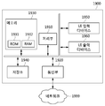
- FIG. 19 is a structural diagram of an encoding apparatus according to an embodiment.
- the encoding apparatus 1900 includes a processing unit 1910, a memory 1930, a user interface (UI) input device 1950, a UI output device 1960, and storage that communicate with each other through a bus 1990. (1940) may be included.
- the encoding apparatus 1900 may further include a communication unit 1920 connected to the network 1999.
- the processing unit 1910 may be a semiconductor device that executes processing instructions stored in a central processing unit (CPU), a memory 1930 or the storage 1940.
- the processing unit 1910 may be at least one hardware processor.
- the processing unit 1910 may generate and process signals, data, or information input to the device 1900, output from the device 1900, or used inside the device 1900. You can perform tests, comparisons, and judgments related to. That is to say, in the embodiment, generation and processing of data or information, and inspection, comparison, and determination related to data or information may be performed by the processing unit 1910.
- At least some of the elements constituting the processing unit 1910 may be program modules, and may communicate with an external device or system.
- Program modules may be included in the encoding apparatus 1900 in the form of an operating system, an application program module, and other program modules.
- Program modules may be physically stored on various known storage devices.
- at least some of these program modules may be stored in a remote storage device capable of communicating with the encoding device 1900.
- Program modules are routines, subroutines, programs, objects, components, and data that perform functions or operations according to an embodiment or implement abstract data types according to an embodiment.
- the structure may be included, but is not limited thereto.
- the program modules may be composed of an instruction or code executed by at least one processor of the encoding apparatus 1900.
- the processing unit 1910 may correspond to the above-described encoder. In other words, the encoding operation of the encoder described above with reference to FIG. 17 and the automatic encoder described above with reference to FIG. 9 may be performed by the processing unit 1910.
- the storage unit may represent the memory 1930 and/or the storage 1940.
- the memory 1930 and the storage 1940 may be various types of volatile or nonvolatile storage media.
- the memory 1930 may include at least one of a ROM 1931 and a RAM 1932.
- the storage unit may store data or information used for the operation of the encoding apparatus 1900.
- data or information of the encoding apparatus 1900 may be stored in a storage unit.
- the encoding apparatus 1900 may be implemented in a computer system including a recording medium that can be read by a computer.
- the recording medium may store at least one module required for the encoding apparatus 1900 to operate.
- the memory 1930 may store at least one module, and at least one module may be configured to be executed by the processing unit 1910.
- a function related to communication of data or information of the encoding apparatus 1900 may be performed through the communication unit 1920.
- the network 1999 may provide communication between the encoding device 1900 and the decoding device 2000.
- 20 is a structural diagram of a decoding apparatus according to an embodiment.
- the decoding apparatus 2000 includes a processing unit 2010 that communicates with each other through a bus 2090, a memory 2030, a user interface (UI) input device 2050, a UI output device 2060, and a storage. It may include (2040). In addition, the decoding apparatus 2000 may further include a communication unit 2020 connected to the network 2099.
- a processing unit 2010 that communicates with each other through a bus 2090, a memory 2030, a user interface (UI) input device 2050, a UI output device 2060, and a storage. It may include (2040).
- the decoding apparatus 2000 may further include a communication unit 2020 connected to the network 2099.
- the processing unit 2010 may be a central processing unit (CPU), a semiconductor device that executes processing instructions stored in the memory 2030 or the storage 2040.
- the processing unit 2010 may be at least one hardware processor.
- the processing unit 2010 may generate and process signals, data, or information input to the device 2000, output from the device 2000, or used inside the device 2000, and You can perform tests, comparisons, and judgments related to. That is to say, in the embodiment, generation and processing of data or information, and inspection, comparison, and determination related to data or information may be performed by the processing unit 2010.
- At least some of the elements constituting the processing unit 2010 may be program modules, and may communicate with an external device or system.
- Program modules may be included in the decoding apparatus 2000 in the form of an operating system, an application program module, and other program modules.
- Program modules may be physically stored on various known storage devices.
- at least some of these program modules may be stored in a remote storage device capable of communicating with the decoding device 2000.
- Program modules are routines, subroutines, programs, objects, components, and data that perform functions or operations according to an embodiment or implement abstract data types according to an embodiment.
- the structure may be included, but is not limited thereto.
- the program modules may be composed of instructions or codes executed by at least one processor of the decoding apparatus 2000.
- the processing unit 2010 may correspond to the above-described decoder. In other words, the decoding operation of the decoder described above with reference to FIG. 18 and the automatic encoder described above with reference to FIG. 9 may be performed by the processing unit 2010.
- the storage unit may represent the memory 2030 and/or the storage 2040.
- the memory 2030 and the storage 2040 may be various types of volatile or nonvolatile storage media.
- the memory 2030 may include at least one of a ROM 2031 and a RAM 2032.
- the storage unit may store data or information used for the operation of the decoding apparatus 2000.
- data or information of the decoding apparatus 2000 may be stored in a storage unit.
- the decoding apparatus 2000 may be implemented in a computer system including a recording medium that can be read by a computer.
- the recording medium may store at least one module required for the decoding apparatus 2000 to operate.
- the memory 2030 may store at least one module, and at least one module may be configured to be executed by the processing unit 2010.
- a function related to communication of data or information of the decoding apparatus 2000 may be performed through the communication unit 2020.
- the network 2099 may provide communication between the encoding device 1900 and the decoding device 2000.
- 21 is a flowchart of an encoding method according to an embodiment.
- step 2110 the processing unit 1910 of the encoding apparatus 1900 may generate a bitstream.
- the processor 1910 may generate a bitstream by performing entropy encoding using an entropy model on the input image.
- the processing unit 1910 may perform an operation for encoding the encoder described above with reference to FIG. 17 and the automatic encoder described above with reference to FIG. 9.
- the processing unit 1910 may use an image compression network and a quality enhancement network for encoding.
- the communication unit 1920 of the encoding apparatus 1900 may transmit a bitstream.
- the communication unit 1920 may transmit the bitstream to the decoding apparatus 2000.
- the bitstream may be stored in the storage unit of the encoding apparatus 1900.
- 22 is a flowchart of a decoding method according to an embodiment.
- step 2210 the communication unit 2020 or the storage unit of the decoding apparatus 2000 may obtain a bitstream.
- step 2220 the processing unit 2010 of the decoding apparatus 2000 may generate a reconstructed image using the bitstream.
- the processing unit 2010 of the decoding apparatus 2000 may generate a reconstructed image by performing decoding using an entropy model on the bitstream.
- the processor 2010 may perform an operation for decoding of the decoder described above with reference to FIG. 18 and the automatic encoder described above with reference to FIG. 9.
- the processing unit 2010 may use an image compression network and a quality improvement network for decoding.
- 23 illustrates padding with an input image according to an example.
- a padding method can be used to obtain a high level of MS-SSIM.
- 1/2 of down-scaling may be performed in the steps of generating y and generating z . Therefore, when the size of the input image is a multiple of 2 n , the maximum compression performance can be derived.
- n may be the number of down-scaling for the input image.
- the padding is formed in the center of the input image rather than the padding for the boundary of the input image.
- FIG. 24 illustrates a code for padding in encoding according to an embodiment.
- 25 is a flowchart of a padding method in encoding according to an embodiment.
- Step 2110 described above with reference to FIG. 21 may include steps 2510, 2520, 2530 and 2540.
- the reference value k may be 2 n .
- n may be the number of down-scalings for the input image in the image compression network.
- the processor 1910 may determine whether to apply horizontal padding to the input image.
- the horizontal padding may be the insertion of one or more rows at the center of the vertical axis of the input image.
- the processor 1910 may determine whether to apply horizontal padding to the input image based on the height h and the reference value k of the input image.
- the processor 1910 may apply horizontal padding to the input image if the height h of the input image is not a multiple of the reference value k . If the height h of the input image is a multiple of the reference value k, the processor 1910 may not apply horizontal padding to the input image.
- step 2520 may be performed.
- step 2530 may be performed.
- the processor 1910 may apply padding in the horizontal direction to the input image.
- the processing unit 1910 may add a padding area between the upper area of the input image and the lower area of the input image.
- the processing unit 1910 may adjust the height of the input image to be a multiple of the reference value k by applying padding in the horizontal direction to the input image.
- the processor 1910 may generate an upper image and a lower image by separating the input image in a vertical direction.
- the processing unit 1910 may apply padding between the upper image and the lower image.
- the processing unit 1910 may generate a padding area.
- the processing unit 1910 may generate an input image whose height is adjusted by combining the upper image, the padding area, and the lower image.
- the padding may be edge padding.
- step 2530 the processor 1910 may determine whether to apply vertical padding to the input image.
- Padding in the vertical direction may be the insertion of one or more columns at the center of the horizontal axis of the input image.
- the processor 1910 may determine whether to apply vertical padding to the input image based on the width w and the reference value k of the input image.
- the processor 1910 may apply vertical padding to the input image if the width w of the input image is not a multiple of the reference value k .
- the processor 1910 may not apply vertical padding to the input image if the area w of the input image is a multiple of the reference value k .
- step 2540 may be performed.
- the procedure may be terminated.
- the processor 1910 may apply vertical padding to the input image.
- the processor 1910 may add a padding area between the left area of the input image and the right area of the input image.
- the processor 1910 may adjust the width of the input image to be a multiple of the reference value k by applying vertical padding to the input image.
- the processor 1910 may generate a left image and a right image by separating the input image in a vertical direction.
- the processing unit 1910 may apply padding between the left image and the right image.
- the processing unit 1910 may generate a padding area.
- the processing unit 1910 may generate an input image whose width is adjusted by combining the left image, the padding area, and the right image.
- the padding may be edge padding.
- a padded image may be generated through the padding of the above-described steps 2510, 2520, 2530, and 2540.
- the width and height of the padded image may be multiples of the reference value k , respectively.
- the padded image can be used to replace the input image.
- 26 illustrates a code for removing a padding area in encoding according to an embodiment.
- FIG. 27 is a flowchart of a method of removing padding in encoding according to an embodiment.
- Step 2220 described above with reference to FIG. 22 may include steps 2710, 2720, 2730 and 2740.
- the target image may be an image reconstructed from the image to which the padding of the embodiment described above is applied with reference to FIG. 25.
- the target image may be an image generated through padding, encoding, and decoding of the input image.
- the height h of the original image may mean the height of the input image before the horizontal direction padding is applied.
- the width w of the original image may mean the width of the input image before vertical padding is applied.
- the reference value k may be 2 n .
- n may be the number of down-scalings for the input image in the image compression network.
- the processing unit 2010 may determine whether to remove the padding area in the horizontal direction from the target image.
- the removal of the padding area in the horizontal direction may be removing one or more rows from the center on the vertical axis of the target image.
- the processor 2010 may determine whether to remove the horizontal padding area from the target image based on the height h and the reference value k of the original image. If the height h of the original image is not a multiple of the reference value k, the processor 2010 may remove the padding area in the horizontal direction from the target image. If the height h of the original image is a multiple of the reference value k, the processing unit 2010 may not remove the horizontal padding area from the target image.
- the processor 2010 may determine whether to remove the horizontal padding area from the target image from the image based on the height h of the original image and the height of the target image. If the height h of the original image and the height of the target image are not the same, the processor 2010 may remove the padding area in the horizontal direction from the target image. If the height h of the original image and the height of the target image are the same, the processing unit 2010 may not remove the padding area in the horizontal direction from the target image.
- step 2720 When removing the horizontal padding area from the target image, step 2720 may be performed.
- step 2730 may be performed.
- the processor 2010 may remove the horizontal padding area from the target image.
- the processor 2010 may remove the padding area between the upper area of the target image and the lower area of the input image.
- the processing unit 2010 may generate an upper image and a lower image by removing the padding area in the horizontal direction from the target image.
- the processing unit 2010 may adjust the height of the target image by combining the upper image and the lower image.
- the height of the target image may be equal to the height h of the original image.
- the padding area may be an area generated by edge padding.
- step 2730 the processor 2010 may determine whether to remove the vertical padding area from the target image.
- the removal of the padding area in the vertical direction may be the removal of one or more columns from the center on the horizontal axis of the target image.
- the processor 2010 may determine whether to remove the padding area in the vertical direction from the target image based on the area w and the reference value k of the original image. If the area w of the original image is not a multiple of the reference value k, the processing unit 2010 may remove the padding area in the vertical direction from the target image. If the area w of the original image is a multiple of the reference value k, the processing unit 2010 may not remove the vertical padding area from the target image.
- the processor 2010 may determine whether to remove the vertical padding area from the target image from the image based on the width w of the original image and the width of the target image. If the area w of the original image and the area of the target image are not the same, the processor 2010 may remove the padding area in the vertical direction from the target image. If the area w of the original image and the area of the target image are the same, the processor 2010 may not remove the vertical padding area from the target image.
- step 2740 may be performed.
- the procedure may end.
- the processing unit 2010 may remove the padding area in the vertical direction from the target image.
- the processing unit 2010 may remove the padding area between the left area of the target image and the right area of the input image.
- the processor 2010 may generate a left image and a right image by removing the padding area in the vertical direction from the target image.
- the processing unit 2010 may adjust the width of the target image by combining the left image and the right image.
- the padding area may be an area generated by edge padding.
- Padding may be removed from the target image by the above-described steps 2710, 2720, 2730, and 2740.
- the apparatus described above may be implemented as a hardware component, a software component, and/or a combination of a hardware component and a software component.
- the devices and components described in the embodiments include, for example, a processor, a controller, an arithmetic logic unit (ALU), a digital signal processor, a microcomputer, a field programmable array (FPA), It can be implemented using one or more general purpose computers or special purpose computers, such as a programmable logic unit (PLU), a microprocessor, or any other device capable of executing and responding to instructions.
- the processing device may execute an operating system (OS) and one or more software applications executed on the operating system.
- the processing device may access, store, manipulate, process, and generate data in response to the execution of software.
- OS operating system
- the processing device may access, store, manipulate, process, and generate data in response to the execution of software.
- the processing device is a plurality of processing elements and/or a plurality of types of processing elements. It can be seen that it may include.
- the processing device may include a plurality of processors or one processor and one controller.
- other processing configurations are possible, such as a parallel processor.
- the software may include a computer program, code, instructions, or a combination of one or more of these, configuring the processing unit to behave as desired or processed independently or collectively. You can command the device.
- Software and/or data may be interpreted by a processing device or to provide instructions or data to a processing device, of any type of machine, component, physical device, virtual equipment, computer storage medium or device. , Or may be permanently or temporarily embodyed in a transmitted signal wave.
- the software may be distributed over networked computer systems and stored or executed in a distributed manner. Software and data may be stored on one or more computer-readable recording media.
- the method according to the embodiment may be implemented in the form of program instructions that can be executed through various computer means and recorded in a computer-readable medium.
- the computer-readable recording medium may contain information used in embodiments according to the present invention.
- a computer-readable recording medium may include a bitstream, and the bitstream may include information described in embodiments according to the present invention.
- the computer-readable recording medium may include a non-transitory computer-readable medium.
- the computer-readable medium may include program instructions, data files, data structures, and the like alone or in combination.
- the program instructions recorded on the medium may be specially designed and configured for the embodiment, or may be known and usable to those skilled in computer software.
- Examples of computer-readable recording media include magnetic media such as hard disks, floppy disks, and magnetic tapes, optical media such as CD-ROMs and DVDs, and magnetic media such as floptical disks.
- -A hardware device specially configured to store and execute program instructions such as magneto-optical media, and ROM, RAM, flash memory, and the like.
- Examples of the program instructions include not only machine language codes such as those produced by a compiler, but also high-level language codes that can be executed by a computer using an interpreter or the like.
- the hardware device described above may be configured to operate as one or more software modules to perform the operation of the embodiment, and vice versa.
- the apparatus described in the embodiments may include one or more processors and may include a memory.
- the memory may store one or more programs executed by one or more processors.
- One or more programs may perform the operation of the device described in the embodiments.
- one or more programs of the device may perform the operations described in the steps associated with the device among the aforementioned steps. That is to say, the operation of the device described in the embodiment may be executed by one or more programs.
- One or more programs may include a program, an application, and an app of the device described above in the embodiment.
- one of the one or more programs may correspond to a program, an application, and an app of the device described above in the embodiment.
Landscapes
- Engineering & Computer Science (AREA)
- Theoretical Computer Science (AREA)
- Physics & Mathematics (AREA)
- General Physics & Mathematics (AREA)
- Multimedia (AREA)
- Artificial Intelligence (AREA)
- Evolutionary Computation (AREA)
- Signal Processing (AREA)
- Software Systems (AREA)
- Computer Vision & Pattern Recognition (AREA)
- Medical Informatics (AREA)
- Data Mining & Analysis (AREA)
- Computing Systems (AREA)
- General Engineering & Computer Science (AREA)
- Mathematical Physics (AREA)
- Compression Of Band Width Or Redundancy In Fax (AREA)
- Compression Or Coding Systems Of Tv Signals (AREA)
Abstract
L'invention concerne un procédé et un dispositif de compression d'image basée sur l'apprentissage machine utilisant un contexte global. Un réseau de compression d'image de l'invention utilise un réseau d'amélioration de qualité d'image existant pour un schéma d'apprentissage conjoint de bout en bout. Le réseau de compression d'image peut optimiser conjointement la compression d'image et l'amélioration de qualité. Les réseaux de compression d'image et les réseaux d'amélioration d'image peuvent être facilement combinés dans une architecture intégrée qui réduit au minimum la perte totale, et peuvent être facilement combinés et optimisés.
Priority Applications (1)
| Application Number | Priority Date | Filing Date | Title |
|---|---|---|---|
| US17/615,519 US20220277491A1 (en) | 2019-05-31 | 2020-05-29 | Method and device for machine learning-based image compression using global context |
Applications Claiming Priority (4)
| Application Number | Priority Date | Filing Date | Title |
|---|---|---|---|
| KR10-2019-0064882 | 2019-05-31 | ||
| KR20190064882 | 2019-05-31 | ||
| KR10-2020-0065289 | 2020-05-29 | ||
| KR1020200065289A KR20200138079A (ko) | 2019-05-31 | 2020-05-29 | 전역적 문맥을 이용하는 기계 학습 기반의 이미지 압축을 위한 방법 및 장치 |
Publications (1)
| Publication Number | Publication Date |
|---|---|
| WO2020242260A1 true WO2020242260A1 (fr) | 2020-12-03 |
Family
ID=73552402
Family Applications (1)
| Application Number | Title | Priority Date | Filing Date |
|---|---|---|---|
| PCT/KR2020/007039 WO2020242260A1 (fr) | 2019-05-31 | 2020-05-29 | Procédé et dispositif de compression d'image basée sur l'apprentissage machine utilisant un contexte global |
Country Status (2)
| Country | Link |
|---|---|
| US (1) | US20220277491A1 (fr) |
| WO (1) | WO2020242260A1 (fr) |
Cited By (2)
| Publication number | Priority date | Publication date | Assignee | Title |
|---|---|---|---|---|
| US20220277491A1 (en) * | 2019-05-31 | 2022-09-01 | Electronics And Telecommunications Research Institute | Method and device for machine learning-based image compression using global context |
| WO2023155848A1 (fr) * | 2022-02-17 | 2023-08-24 | Beijing Bytedance Network Technology Co., Ltd. | Procédé, appareil, et support de traitement de données |
Families Citing this family (2)
| Publication number | Priority date | Publication date | Assignee | Title |
|---|---|---|---|---|
| US11769227B2 (en) * | 2021-08-12 | 2023-09-26 | Adobe Inc. | Generating synthesized digital images utilizing a multi-resolution generator neural network |
| WO2024083250A1 (fr) * | 2022-10-21 | 2024-04-25 | Douyin Vision Co., Ltd. | Procédé, appareil et support de traitement vidéo |
Citations (4)
| Publication number | Priority date | Publication date | Assignee | Title |
|---|---|---|---|---|
| US20170105005A1 (en) * | 2015-10-07 | 2017-04-13 | Qualcomm Incorporated | Methods and systems of performing predictive random access using a background picture |
| CN106713935A (zh) * | 2017-01-09 | 2017-05-24 | 杭州电子科技大学 | 一种基于贝叶斯决策的hevc块划分快速方法 |
| KR20180001428A (ko) * | 2016-06-24 | 2018-01-04 | 한국과학기술원 | Cnn 기반 인루프 필터를 포함하는 부호화 방법과 장치 및 복호화 방법과 장치 |
| US10225607B1 (en) * | 2018-01-25 | 2019-03-05 | Novatek Microelectronics Corp. | Video processing apparatus and video processing method thereof |
Family Cites Families (22)
| Publication number | Priority date | Publication date | Assignee | Title |
|---|---|---|---|---|
| WO2008118146A1 (fr) * | 2007-03-23 | 2008-10-02 | Thomson Licensing | Modification d'un flux binaire codé |
| US8913666B2 (en) * | 2010-10-01 | 2014-12-16 | Qualcomm Incorporated | Entropy coding coefficients using a joint context model |
| US9042440B2 (en) * | 2010-12-03 | 2015-05-26 | Qualcomm Incorporated | Coding the position of a last significant coefficient within a video block based on a scanning order for the block in video coding |
| US9049452B2 (en) * | 2011-01-25 | 2015-06-02 | Mediatek Singapore Pte. Ltd. | Method and apparatus for compressing coding unit in high efficiency video coding |
| CN107277539B (zh) * | 2011-05-27 | 2020-11-06 | 寰发股份有限公司 | 减少用于上下文自适应熵解码中的行缓存的方法及装置 |
| US8995523B2 (en) * | 2011-06-03 | 2015-03-31 | Qualcomm Incorporated | Memory efficient context modeling |
| ES2853673T3 (es) * | 2011-06-14 | 2021-09-17 | Lg Electronics Inc | Método para codificar y descodificar la información de imágenes |
| CN107105305B (zh) * | 2011-06-24 | 2020-04-03 | Lg 电子株式会社 | 图像信息编码和解码方法 |
| FR2977111A1 (fr) * | 2011-06-24 | 2012-12-28 | France Telecom | Procede de codage et decodage d'images, dispositif de codage et decodage et programmes d'ordinateur correspondants |
| EP2727356A2 (fr) * | 2011-06-30 | 2014-05-07 | Huawei Technologies Co., Ltd | Procédé de codage rapide pour codage sans perte |
| SG10201709427VA (en) * | 2011-07-01 | 2017-12-28 | Samsung Electronics Co Ltd | Method And Apparatus For Entropy Encoding Using Hierarchical Data Unit, And Method And Apparatus For Decoding |
| WO2013042884A1 (fr) * | 2011-09-19 | 2013-03-28 | 엘지전자 주식회사 | Procédé de codage/décodage d'image et dispositif associé |
| US9451287B2 (en) * | 2011-11-08 | 2016-09-20 | Qualcomm Incorporated | Context reduction for context adaptive binary arithmetic coding |
| US9467701B2 (en) * | 2012-04-05 | 2016-10-11 | Qualcomm Incorporated | Coded block flag coding |
| US9538172B2 (en) * | 2012-04-11 | 2017-01-03 | Qualcomm Incorporated | Grouping bypass coded syntax elements in video coding |
| CN104205843A (zh) * | 2012-04-20 | 2014-12-10 | 华为技术有限公司 | Hevc中无损编码中的改进帧内预测 |
| EP3090543A4 (fr) * | 2013-12-30 | 2017-08-02 | QUALCOMM Incorporated | Simplification de codage delta dc par résidus en codage vidéo 3d |
| US20190034734A1 (en) * | 2017-07-28 | 2019-01-31 | Qualcomm Incorporated | Object classification using machine learning and object tracking |
| WO2020009758A1 (fr) * | 2018-07-02 | 2020-01-09 | Interdigital Vc Holdings, Inc. | Codage et décodage arithmétique binaire reposant sur le contexte |
| US11412225B2 (en) * | 2018-09-27 | 2022-08-09 | Electronics And Telecommunications Research Institute | Method and apparatus for image processing using context-adaptive entropy model |
| WO2020242260A1 (fr) * | 2019-05-31 | 2020-12-03 | 한국전자통신연구원 | Procédé et dispositif de compression d'image basée sur l'apprentissage machine utilisant un contexte global |
| BR112022014484A2 (pt) * | 2020-01-23 | 2022-09-13 | Huawei Tech Co Ltd | Método de decodificação de uma sequência de vídeo codificada e decodificador, método de codificação de uma sequência de vídeo e codificador, e mídia legível por computador não transitória |
-
2020
- 2020-05-29 WO PCT/KR2020/007039 patent/WO2020242260A1/fr active Application Filing
- 2020-05-29 US US17/615,519 patent/US20220277491A1/en not_active Abandoned
Patent Citations (4)
| Publication number | Priority date | Publication date | Assignee | Title |
|---|---|---|---|---|
| US20170105005A1 (en) * | 2015-10-07 | 2017-04-13 | Qualcomm Incorporated | Methods and systems of performing predictive random access using a background picture |
| KR20180001428A (ko) * | 2016-06-24 | 2018-01-04 | 한국과학기술원 | Cnn 기반 인루프 필터를 포함하는 부호화 방법과 장치 및 복호화 방법과 장치 |
| CN106713935A (zh) * | 2017-01-09 | 2017-05-24 | 杭州电子科技大学 | 一种基于贝叶斯决策的hevc块划分快速方法 |
| US10225607B1 (en) * | 2018-01-25 | 2019-03-05 | Novatek Microelectronics Corp. | Video processing apparatus and video processing method thereof |
Non-Patent Citations (1)
| Title |
|---|
| LEE, JOOYOUNG ET AL.: "Context-adaptive Entropy Model for End-to-end Optimized Image Compression", ARXIV: 1809.10452V4, 6 May 2019 (2019-05-06), pages 1 - 20, XP081202283, Retrieved from the Internet <URL:https://arxiv.org/abs/1809.10452> [retrieved on 20200814] * |
Cited By (2)
| Publication number | Priority date | Publication date | Assignee | Title |
|---|---|---|---|---|
| US20220277491A1 (en) * | 2019-05-31 | 2022-09-01 | Electronics And Telecommunications Research Institute | Method and device for machine learning-based image compression using global context |
| WO2023155848A1 (fr) * | 2022-02-17 | 2023-08-24 | Beijing Bytedance Network Technology Co., Ltd. | Procédé, appareil, et support de traitement de données |
Also Published As
| Publication number | Publication date |
|---|---|
| US20220277491A1 (en) | 2022-09-01 |
Similar Documents
| Publication | Publication Date | Title |
|---|---|---|
| WO2020242260A1 (fr) | Procédé et dispositif de compression d'image basée sur l'apprentissage machine utilisant un contexte global | |
| WO2017222140A1 (fr) | Procédés et dispositifs de codage et de décodage comprenant un filtre en boucle à base de cnn | |
| WO2009131376A2 (fr) | Système de communication à antennes multiples comprenant la mise à jour et le changement adaptatifs de livres de codes | |
| WO2020190112A1 (fr) | Procédé, appareil, dispositif et support permettant de générer des informations de sous-titrage de données multimédias | |
| WO2020197241A1 (fr) | Dispositif et procédé de compression de modèle d'apprentissage automatique | |
| WO2009157715A2 (fr) | Procédé de conception de livre de codes pour système à multiples entrées et multiples sorties et procédé d'utilisation du livre de codes | |
| WO2012033373A2 (fr) | Codage par transformation de faible complexité utilisant une transformée dct/dst adaptative pour l'intra-prédiction | |
| WO2022005188A1 (fr) | Procédé de reconnaissance d'entité, appareil, dispositif électronique et support de stockage lisible par ordinateur | |
| WO2019009491A1 (fr) | Procédé et dispositif de codage ou de décodage d'image | |
| WO2021162359A1 (fr) | Procédé de traitement d'image et appareil électronique | |
| WO2019074339A1 (fr) | Système et procédé de conversion de signaux | |
| WO2022154457A1 (fr) | Procédé de localisation d'action, dispositif, équipement électronique et support de stockage lisible par ordinateur | |
| EP4367628A1 (fr) | Procédé de traitement d'image et dispositif associé | |
| WO2017155137A1 (fr) | Procédé de formation de faisceau et dispositif associé | |
| WO2011002260A2 (fr) | Livre de code tournant de référence utilisé dans un système de communications à entrées et sorties multiples (mimo) | |
| WO2011040707A2 (fr) | Système de communication entrée multiple sortie multiple utilisant une rétraction explicite | |
| WO2012011755A2 (fr) | Appareil et procédé pour transmettre des données | |
| WO2021256843A1 (fr) | Dispositif et procédé pour effectuer un calcul statistique sur un texte chiffré homomorphe | |
| WO2019045320A1 (fr) | Procédé et dispositif électronique permettant de prédire une structure électronique de matériau | |
| WO2017142299A1 (fr) | Système et procédé pour authentifier une signature manuscrite à base de suivi de mouvement dynamique pour un segment de division spatiale | |
| WO2021112647A1 (fr) | Procédé, appareil et dispositif électronique pour déterminer un vecteur de représentation de mot | |
| WO2024019341A1 (fr) | Dispositif de réception comprenant un coupleur linéaire dans un système mimo pour prendre en charge de multiples numérologies, et procédé de fonctionnement de celui-ci | |
| WO2021137675A1 (fr) | Procédé et appareil de positionnement | |
| WO2024043617A1 (fr) | Dispositif de codage d'image et dispositif de décodage d'image basés sur l'ia, et procédé de codage et de décodage d'image les utilisant | |
| WO2022034967A1 (fr) | Filtre de diversité à retard adaptatif, et dispositif d'annulation d'écho et procédé l'utilisant |
Legal Events
| Date | Code | Title | Description |
|---|---|---|---|
| 121 | Ep: the epo has been informed by wipo that ep was designated in this application |
Ref document number: 20813538 Country of ref document: EP Kind code of ref document: A1 |
|
| NENP | Non-entry into the national phase |
Ref country code: DE |
|
| 122 | Ep: pct application non-entry in european phase |
Ref document number: 20813538 Country of ref document: EP Kind code of ref document: A1 |