WO2020242109A1 - Procédé et appareil pour la réception de mu ppdu dans un système lan sans fil - Google Patents
Procédé et appareil pour la réception de mu ppdu dans un système lan sans fil Download PDFInfo
- Publication number
- WO2020242109A1 WO2020242109A1 PCT/KR2020/006519 KR2020006519W WO2020242109A1 WO 2020242109 A1 WO2020242109 A1 WO 2020242109A1 KR 2020006519 W KR2020006519 W KR 2020006519W WO 2020242109 A1 WO2020242109 A1 WO 2020242109A1
- Authority
- WO
- WIPO (PCT)
- Prior art keywords
- sig
- field
- ppdu
- sta
- eht
- Prior art date
Links
- 238000000034 method Methods 0.000 title claims abstract description 100
- 230000015654 memory Effects 0.000 claims description 31
- 230000010363 phase shift Effects 0.000 claims description 6
- VXQBJTKSVGFQOL-UHFFFAOYSA-N 2-(2-butoxyethoxy)ethyl acetate Chemical compound CCCCOCCOCCOC(C)=O VXQBJTKSVGFQOL-UHFFFAOYSA-N 0.000 claims 2
- 230000005540 biological transmission Effects 0.000 description 44
- 230000004044 response Effects 0.000 description 23
- 238000004891 communication Methods 0.000 description 22
- 230000008569 process Effects 0.000 description 22
- 238000012545 processing Methods 0.000 description 17
- 238000013528 artificial neural network Methods 0.000 description 14
- 238000010586 diagram Methods 0.000 description 13
- 230000006870 function Effects 0.000 description 12
- 101100042610 Arabidopsis thaliana SIGB gene Proteins 0.000 description 11
- 241001591005 Siga Species 0.000 description 11
- 101150117326 sigA gene Proteins 0.000 description 11
- 239000000523 sample Substances 0.000 description 10
- 238000012549 training Methods 0.000 description 10
- 238000005516 engineering process Methods 0.000 description 9
- 238000010801 machine learning Methods 0.000 description 9
- 101100161473 Arabidopsis thaliana ABCB25 gene Proteins 0.000 description 8
- 101100096893 Mus musculus Sult2a1 gene Proteins 0.000 description 8
- 101150081243 STA1 gene Proteins 0.000 description 8
- 238000007726 management method Methods 0.000 description 8
- OVGWMUWIRHGGJP-WVDJAODQSA-N (z)-7-[(1s,3r,4r,5s)-3-[(e,3r)-3-hydroxyoct-1-enyl]-6-thiabicyclo[3.1.1]heptan-4-yl]hept-5-enoic acid Chemical compound OC(=O)CCC\C=C/C[C@@H]1[C@@H](/C=C/[C@H](O)CCCCC)C[C@@H]2S[C@H]1C2 OVGWMUWIRHGGJP-WVDJAODQSA-N 0.000 description 7
- 101000988961 Escherichia coli Heat-stable enterotoxin A2 Proteins 0.000 description 7
- 210000002569 neuron Anatomy 0.000 description 7
- 101100421503 Arabidopsis thaliana SIGA gene Proteins 0.000 description 4
- 238000013473 artificial intelligence Methods 0.000 description 4
- 238000004364 calculation method Methods 0.000 description 4
- 239000013256 coordination polymer Substances 0.000 description 4
- 238000013135 deep learning Methods 0.000 description 4
- 230000008054 signal transmission Effects 0.000 description 4
- 101000752249 Homo sapiens Rho guanine nucleotide exchange factor 3 Proteins 0.000 description 3
- 102100021689 Rho guanine nucleotide exchange factor 3 Human genes 0.000 description 3
- 230000001419 dependent effect Effects 0.000 description 3
- 230000002829 reductive effect Effects 0.000 description 3
- 230000011664 signaling Effects 0.000 description 3
- 210000000225 synapse Anatomy 0.000 description 3
- 230000009471 action Effects 0.000 description 2
- 230000004913 activation Effects 0.000 description 2
- 230000002776 aggregation Effects 0.000 description 2
- 238000004220 aggregation Methods 0.000 description 2
- VYLDEYYOISNGST-UHFFFAOYSA-N bissulfosuccinimidyl suberate Chemical compound O=C1C(S(=O)(=O)O)CC(=O)N1OC(=O)CCCCCCC(=O)ON1C(=O)C(S(O)(=O)=O)CC1=O VYLDEYYOISNGST-UHFFFAOYSA-N 0.000 description 2
- 230000009977 dual effect Effects 0.000 description 2
- 238000013507 mapping Methods 0.000 description 2
- 238000010295 mobile communication Methods 0.000 description 2
- 230000002787 reinforcement Effects 0.000 description 2
- 101100395869 Escherichia coli sta3 gene Proteins 0.000 description 1
- 101000741965 Homo sapiens Inactive tyrosine-protein kinase PRAG1 Proteins 0.000 description 1
- 102100038659 Inactive tyrosine-protein kinase PRAG1 Human genes 0.000 description 1
- 108700026140 MAC combination Proteins 0.000 description 1
- -1 and accordingly Proteins 0.000 description 1
- 230000003190 augmentative effect Effects 0.000 description 1
- 230000001186 cumulative effect Effects 0.000 description 1
- 230000007423 decrease Effects 0.000 description 1
- 230000003247 decreasing effect Effects 0.000 description 1
- 230000000694 effects Effects 0.000 description 1
- 238000003780 insertion Methods 0.000 description 1
- 230000037431 insertion Effects 0.000 description 1
- 230000000670 limiting effect Effects 0.000 description 1
- 230000007774 longterm Effects 0.000 description 1
- 239000011159 matrix material Substances 0.000 description 1
- 230000036961 partial effect Effects 0.000 description 1
- 238000013468 resource allocation Methods 0.000 description 1
- 230000003068 static effect Effects 0.000 description 1
- 230000000946 synaptic effect Effects 0.000 description 1
- 238000012546 transfer Methods 0.000 description 1
Images


Classifications
-
- H—ELECTRICITY
- H04—ELECTRIC COMMUNICATION TECHNIQUE
- H04L—TRANSMISSION OF DIGITAL INFORMATION, e.g. TELEGRAPHIC COMMUNICATION
- H04L5/00—Arrangements affording multiple use of the transmission path
- H04L5/0091—Signaling for the administration of the divided path
- H04L5/0092—Indication of how the channel is divided
-
- H—ELECTRICITY
- H04—ELECTRIC COMMUNICATION TECHNIQUE
- H04L—TRANSMISSION OF DIGITAL INFORMATION, e.g. TELEGRAPHIC COMMUNICATION
- H04L27/00—Modulated-carrier systems
- H04L27/26—Systems using multi-frequency codes
- H04L27/2601—Multicarrier modulation systems
- H04L27/2602—Signal structure
- H04L27/2603—Signal structure ensuring backward compatibility with legacy system
-
- H—ELECTRICITY
- H04—ELECTRIC COMMUNICATION TECHNIQUE
- H04W—WIRELESS COMMUNICATION NETWORKS
- H04W72/00—Local resource management
- H04W72/04—Wireless resource allocation
- H04W72/044—Wireless resource allocation based on the type of the allocated resource
- H04W72/0453—Resources in frequency domain, e.g. a carrier in FDMA
-
- H—ELECTRICITY
- H04—ELECTRIC COMMUNICATION TECHNIQUE
- H04W—WIRELESS COMMUNICATION NETWORKS
- H04W72/00—Local resource management
- H04W72/50—Allocation or scheduling criteria for wireless resources
- H04W72/51—Allocation or scheduling criteria for wireless resources based on terminal or device properties
-
- H—ELECTRICITY
- H04—ELECTRIC COMMUNICATION TECHNIQUE
- H04W—WIRELESS COMMUNICATION NETWORKS
- H04W84/00—Network topologies
- H04W84/02—Hierarchically pre-organised networks, e.g. paging networks, cellular networks, WLAN [Wireless Local Area Network] or WLL [Wireless Local Loop]
- H04W84/10—Small scale networks; Flat hierarchical networks
- H04W84/12—WLAN [Wireless Local Area Networks]
-
- H—ELECTRICITY
- H04—ELECTRIC COMMUNICATION TECHNIQUE
- H04L—TRANSMISSION OF DIGITAL INFORMATION, e.g. TELEGRAPHIC COMMUNICATION
- H04L27/00—Modulated-carrier systems
- H04L27/26—Systems using multi-frequency codes
- H04L27/2601—Multicarrier modulation systems
- H04L27/2602—Signal structure
-
- H—ELECTRICITY
- H04—ELECTRIC COMMUNICATION TECHNIQUE
- H04L—TRANSMISSION OF DIGITAL INFORMATION, e.g. TELEGRAPHIC COMMUNICATION
- H04L5/00—Arrangements affording multiple use of the transmission path
- H04L5/003—Arrangements for allocating sub-channels of the transmission path
- H04L5/0048—Allocation of pilot signals, i.e. of signals known to the receiver
-
- H—ELECTRICITY
- H04—ELECTRIC COMMUNICATION TECHNIQUE
- H04L—TRANSMISSION OF DIGITAL INFORMATION, e.g. TELEGRAPHIC COMMUNICATION
- H04L5/00—Arrangements affording multiple use of the transmission path
- H04L5/0091—Signaling for the administration of the divided path
- H04L5/0096—Indication of changes in allocation
- H04L5/0098—Signalling of the activation or deactivation of component carriers, subcarriers or frequency bands
Definitions
- the present specification relates to a technique for receiving an MU PPDU in a wireless LAN system, and more particularly, to a method and apparatus for designing an MU PPDU for simultaneously transmitting data to an HE STA and an EHT STA in a broadband.
- WLAN wireless local area network
- OFDMA orthogonal frequency division multiple access
- MIMO downlink multi-user multiple input, multiple output
- the new communication standard may be an extreme high throughput (EHT) standard that is currently being discussed.
- the EHT standard may use a newly proposed increased bandwidth, an improved PHY layer protocol data unit (PPDU) structure, an improved sequence, and a hybrid automatic repeat request (HARQ) technique.
- PPDU PHY layer protocol data unit
- HARQ hybrid automatic repeat request
- the EHT standard can be referred to as the IEEE 802.11be standard.
- an increased number of spatial streams can be used.
- a signaling technique in the WLAN system may need to be improved.
- This specification proposes a method and apparatus for receiving an MU PPDU in a wireless LAN system.
- An example of the present specification proposes a method of receiving an MU PPDU.
- This embodiment proposes a method of simultaneously transmitting data to an HE STA (802.11ax STA) and an EHT STA (802.11be STA) using one MU PPDU in a wideband (240 MHz, 320 MHz band) supported by the EHT WLAN system. do.
- the broadband tone plan may be designed by repeating the 80MHz tone plan of the existing 802.11ax.
- This embodiment is performed in a receiving STA and may correspond to an STA supporting an Extremely High Throughput (EHT) wireless LAN system.
- the transmitting STA of this embodiment may correspond to an access point (AP).
- AP access point
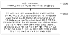
- the receiving STA receives the MU PPDU (Multi-User Physical Protocol Data Unit) from the transmitting STA.
- MU PPDU Multi-User Physical Protocol Data Unit
- the receiving STA decodes the MU PPDU.
- the receiving STA means a plurality of receiving STAs, and includes an HE STA and an EHT STA.
- the MU PPDU includes an L-SIG (Legacy-Signal) field, an RL-SIG (Repeated Legacy-Signal) field, a HE-SIG (High Efficiency-Signal) field, and an EHT-SIG (Extremely High Throughput-Signal) field.
- the HE STA may decode the L-SIG field, the RL-SIG field, and the HE-SIG field.
- the EHT STA may decode the L-SIG field, the RL-SIG field, the HE-SIG field, and the EHT-SIG field.
- the first reserved bit of the L-SIG field includes information that the first band in which the MU PPDU is transmitted is greater than 160 MHz. That is, the transmitting STA may inform the EHT STA that the MU PPDU is an EHT MU PPDU and that a band in which the MU PPDU is transmitted is greater than 160 MHz by using the first reserved bit.
- the second reserved bit of the HE-SIG field includes information on a size of the first band or a second band through which the EHT-SIG field is transmitted.
- the HE-SIG field may include information on the third band allocated to the HE STA (corresponding to the bandwidth field of the HE-SIG-A field).
- the third band may be a primary 80MHz or a primary 160MHz. That is, data for the HE STA may be allocated only within a primary 160 MHz of the MU PPDU (EHT MU PPDU).
- the transmitting STA informs the EHT STA that the band in which the MU PPDU is transmitted is 240 MHz or 320 MHz by using the second reserved bit, or the band in which the EHT-SIG field is transmitted in the MU PPDU (second band) Alternatively, information about the channel can be announced.
- the band (or channel) in which the EHT-SIG field is transmitted may be set to a band (or channel) other than the band (or channel) set in the bandwidth field of the HE-SIG-A field. That is, if the third band is set by the HE-SIG field, the EHT-SIG field may be allocated to a band other than the third band in the first band.
- the technical characteristics of the 11ax wireless LAN system can be used as it is by designing the tone plan in the broadband by using the tone plan for the existing 11ax 80MHz band as it is.
- the present specification has a new effect of increasing data transmission efficiency and overall throughput by designing one MU PPDU for simultaneously transmitting data to an HE STA and an EHT STA in a broadband.
- FIG. 1 shows an example of a transmitting device and/or a receiving device of the present specification.
- WLAN wireless LAN
- FIG. 3 is a diagram illustrating a general link setup process.
- FIG. 4 is a diagram showing an example of a PPDU used in the IEEE standard.
- FIG. 5 is a diagram showing an arrangement of resource units (RU) used in a 20 MHz band.
- FIG. 6 is a diagram showing an arrangement of a resource unit (RU) used in a 40 MHz band.
- RU resource unit
- RU 7 is a diagram showing the arrangement of resource units (RU) used in the 80MHz band.
- FIG. 11 shows an example of a trigger frame.
- FIG. 13 shows an example of a subfield included in a per user information field.
- 15 shows an example of a channel used/supported/defined within a 2.4 GHz band.
- 16 shows an example of a channel used/supported/defined within a 5 GHz band.
- FIG. 17 shows an example of a channel used/supported/defined within a 6 GHz band.
- 21 shows an example of a 320MHz MU PPDU proposed in this embodiment.
- FIG. 22 shows another example of a 320MHz MU PPDU proposed in this embodiment.
- 25 shows another example of a 320MHz MU PPDU proposed in this embodiment.
- 26 shows another example of a 320MHz MU PPDU proposed in this embodiment.
- FIG. 27 shows another example of a 320MHz MU PPDU proposed in this embodiment.
- 29 shows another example of a 160MHz MU PPDU proposed in this embodiment.
- FIG. 30 shows another example of a 160MHz MU PPDU proposed in this embodiment.
- 31 shows another example of a 160MHz MU PPDU proposed in this embodiment.
- 34 is a flowchart showing the operation of the receiving device according to the present embodiment.
- 35 is a flowchart illustrating a procedure for transmitting an MU PPDU from a transmitting STA according to the present embodiment.
- 36 is a flowchart illustrating a procedure for receiving an MU PPDU in a receiving STA according to this embodiment.
- a or B (A or B) may mean “only A”, “only B” or “both A and B”.
- a or B (A or B)” may be interpreted as “A and/or B (A and/or B)”.
- A, B or C (A, B or C) refers to “only A”, “only B”, “only C” or “A, B and C” in any and all combinations (any It can mean a combination of A, B and C)”.
- a forward slash (/) or comma used in the present specification may mean “and/or”.
- A/B may mean “and/or B”.
- A/B may mean “only A”, “only B”, or “both A and B”.
- A, B, C may mean “A, B or C”.
- At least one of A and B may mean “only A”, “only B” or “both A and B”.
- the expression “at least one of A or B” or “at least one of A and/or B” means “at least one Can be interpreted the same as “at least one of A and B”.
- “at least one of A, B and C” means “only A”, “only B”, “only C” or “A, B and C. It can mean any combination of A, B and C”. Also, “at least one of A, B or C” or “at least one of A, B and/or C” It can mean “at least one of A, B and C”.
- control information EHT-Signal
- EHT-Signal when displayed as “control information (EHT-Signal)”, “EHT-Signal” may be proposed as an example of “control information”.
- control information of the present specification is not limited to “EHT-Signal”, and “EHT-Signal” may be suggested as an example of “control information”.
- EHT-signal even when displayed as “control information (ie, EHT-signal)”, “EHT-Signal” may be proposed as an example of “control information”.
- the following example of the present specification can be applied to various wireless communication systems.
- the following example of the present specification may be applied to a wireless local area network (WLAN) system.
- WLAN wireless local area network
- this specification can be applied to the IEEE 802.11a/g/n/ac standard or the IEEE 802.11ax standard.
- this specification can be applied to the newly proposed EHT standard or IEEE 802.11be standard.
- an example of the present specification may be applied to the EHT standard or to a new wireless LAN standard that is improved (enhance) IEEE 802.11be.
- an example of the present specification may be applied to a mobile communication system.
- LTE Long Term Evolution
- 3GPP 3rd Generation Partnership Project
- an example of the present specification may be applied to a communication system of 5G NR standard based on 3GPP standard.
- FIG. 1 shows an example of a transmitting device and/or a receiving device of the present specification.
- the example of FIG. 1 may perform various technical features described below. 1 is related to at least one STA (station).
- the STAs 110 and 120 of the present specification include a mobile terminal, a wireless device, a wireless transmit/receive unit (WTRU), a user equipment (UE), It may be referred to by various names such as a mobile station (MS), a mobile subscriber unit, or simply a user.
- STAs 110 and 120 of the present specification may be referred to by various names such as a network, a base station, a Node-B, an access point (AP), a repeater, a router, and a relay.
- the STAs 110 and 120 of the present specification may be referred to by various names such as a receiving device, a transmitting device, a receiving STA, a transmitting STA, a receiving device, and a transmitting device.
- the STAs 110 and 120 may perform an access point (AP) role or a non-AP role. That is, the STAs 110 and 120 of the present specification may perform functions of an AP and/or a non-AP.
- the AP may also be indicated as an AP STA.
- the STAs 110 and 120 of the present specification may support various communication standards other than the IEEE 802.11 standard together.
- communication standards eg, LTE, LTE-A, 5G NR standards
- the STA of the present specification may be implemented with various devices such as a mobile phone, a vehicle, and a personal computer.
- the STA of the present specification may support communication for various communication services such as voice call, video call, data communication, and autonomous driving (Self-Driving, Autonomous-Driving).
- the STAs 110 and 120 may include a medium access control (MAC) and a physical layer interface for a wireless medium according to the IEEE 802.11 standard.
- MAC medium access control
- the STAs 110 and 120 will be described on the basis of the sub-drawing (a) of FIG. 1 as follows.
- the first STA 110 may include a processor 111, a memory 112, and a transceiver 113.
- the illustrated processor, memory, and transceiver may each be implemented as separate chips, or at least two or more blocks/functions may be implemented through a single chip.
- the transceiver 113 of the first STA performs a signal transmission/reception operation.
- IEEE 802.11 packets eg, IEEE 802.11a/b/g/n/ac/ax/be, etc.
- IEEE 802.11a/b/g/n/ac/ax/be, etc. can be transmitted and received.
- the first STA 110 may perform an intended operation of the AP.
- the processor 111 of the AP may receive a signal through the transceiver 113, process a received signal, generate a transmission signal, and perform control for signal transmission.
- the memory 112 of the AP may store a signal (ie, a received signal) received through the transceiver 113 and may store a signal (ie, a transmission signal) to be transmitted through the transceiver.
- the second STA 120 may perform an intended operation of a non-AP STA.
- the non-AP transceiver 123 performs a signal transmission/reception operation.
- IEEE 802.11 packets eg, IEEE 802.11a/b/g/n/ac/ax/be, etc.
- IEEE 802.11a/b/g/n/ac/ax/be, etc. can be transmitted and received.
- the processor 121 of the non-AP STA may receive a signal through the transceiver 123, process a received signal, generate a transmission signal, and perform control for signal transmission.
- the memory 122 of the non-AP STA may store a signal (ie, a reception signal) received through the transceiver 123 and may store a signal (ie, a transmission signal) to be transmitted through the transceiver.
- an operation of a device indicated as an AP may be performed by the first STA 110 or the second STA 120.
- the operation of the device indicated as an AP is controlled by the processor 111 of the first STA 110 and is controlled by the processor 111 of the first STA 110.
- a related signal may be transmitted or received through the controlled transceiver 113.
- control information related to the operation of the AP or a transmission/reception signal of the AP may be stored in the memory 112 of the first STA 110.
- the operation of the device indicated as an AP is controlled by the processor 121 of the second STA 120 and controlled by the processor 121 of the second STA 120.
- a related signal may be transmitted or received through the transceiver 123 being used.
- control information related to the operation of the AP or transmission/reception signals of the AP may be stored in the memory 122 of the second STA 110.
- an operation of a device indicated as non-AP may be performed by the first STA 110 or the second STA 120.
- the operation of the device marked as non-AP is controlled by the processor 121 of the second STA 120 and the processor of the second STA 120 ( A related signal may be transmitted or received through the transceiver 123 controlled by 121).
- control information related to the operation of the non-AP or transmission/reception signals of the AP may be stored in the memory 122 of the second STA 120.
- the operation of the device marked as non-AP is controlled by the processor 111 of the first STA 110 and the processor of the first STA 120 ( A related signal may be transmitted or received through the transceiver 113 controlled by 111).
- control information related to the operation of the non-AP or transmission/reception signals of the AP may be stored in the memory 112 of the first STA 110.
- (transmit/receive) STA, first STA, second STA, STA1, STA2, AP, first AP, second AP, AP1, AP2, (transmit/receive) Terminal, (transmit/receive) device , (Transmission/reception) apparatus, a device called a network, etc. may refer to the STAs 110 and 120 of FIG. 1.
- an operation in which various STAs transmit and receive signals may be performed by the transceivers 113 and 123 of FIG. 1.
- an operation in which various STAs generate transmission/reception signals or perform data processing or calculation in advance for transmission/reception signals may be performed by the processors 111 and 121 of FIG. 1.
- an example of an operation of generating a transmission/reception signal or performing data processing or calculation in advance for a transmission/reception signal is: 1) Determining bit information of a subfield (SIG, STF, LTF, Data) field included in the PPDU.
- Time resources or frequency resources eg, subcarrier resources
- SIG, STF, LTF, Data Time resources or frequency resources
- Determination/configuration/retrieve operation 3) A specific sequence used for the subfields (SIG, STF, LTF, Data) fields included in the PPDU (e.g., pilot sequence, STF/LTF sequence, applied to SIG)
- An operation of determining/configuring/obtaining an extra sequence 4) a power control operation and/or a power saving operation applied to the STA, 5) an operation related to determination/acquisition/configuration/calculation/decoding/encoding of an ACK signal, etc.
- various information used by various STAs for determination/acquisition/configuration/calculation/decoding/encoding of transmission/reception signals (for example, information related to fields/subfields/control fields/parameters/power, etc.) It may be stored in the memories 112 and 122 of FIG. 1.
- the device/STA of the sub-drawing (a) of FIG. 1 described above may be modified as in the sub-drawing (b) of FIG. 1.
- the STAs 110 and 120 of the present specification will be described based on the sub-drawing (b) of FIG. 1.
- the transceivers 113 and 123 illustrated in sub-drawing (b) of FIG. 1 may perform the same functions as the transceiver illustrated in sub-drawing (a) of FIG. 1.
- the processing chips 114 and 124 shown in sub-drawing (b) of FIG. 1 may include processors 111 and 121 and memories 112 and 122.
- the processors 111 and 121 and the memories 112 and 122 illustrated in sub-drawing (b) of FIG. 1 are the processors 111 and 121 and the memories 112 and 122 illustrated in sub-drawing (a) of FIG. ) And can perform the same function.
- the STA, the receiving device, the transmitting device, the receiving Apparatus, and/or the transmitting Apparatus refer to the STAs 110 and 120 shown in sub-drawings (a)/(b) of FIG. 1, or the sub-drawing (b) of FIG. ) May mean processing chips 114 and 124 shown in FIG.
- the technical features of the present specification may be performed on the STAs 110 and 120 shown in sub-drawings (a)/(b) of FIG. 1, and the processing chip shown in sub-drawing (b) of FIG. 114, 124).
- the technical feature of the transmitting STA transmitting the control signal is that the control signal generated by the processors 111 and 121 shown in sub-drawings (a)/(b) of FIG. 1 is sub-drawing (a) of FIG. It can be understood as a technical feature transmitted through the transceivers 113 and 123 shown in )/(b).
- the technical feature in which the transmitting STA transmits the control signal is a technical feature in which a control signal to be transmitted to the transceivers 113 and 123 is generated from the processing chips 114 and 124 shown in sub-drawing (b) of FIG. 1. Can be understood.
- the technical characteristic that the receiving STA receives the control signal may be understood as a technical characteristic in which the control signal is received by the transceivers 113 and 123 shown in sub-drawing (a) of FIG. 1.
- the technical feature that the receiving STA receives the control signal is that the control signal received by the transceivers 113 and 123 shown in sub-drawing (a) of FIG. 1 is the processor shown in sub-drawing (a) of FIG. 111, 121) can be understood as a technical feature obtained.
- the technical feature that the receiving STA receives the control signal is that the control signal received by the transceivers 113 and 123 shown in sub-drawing (b) of FIG. 1 is a processing chip shown in sub-drawing (b) of FIG. It can be understood as a technical feature obtained by (114, 124).
- software codes 115 and 125 may be included in the memories 112 and 122.
- the software codes 115 and 125 may include instructions for controlling the operations of the processors 111 and 121.
- the software codes 115 and 125 may be included in various programming languages.
- the processors 111 and 121 or the processing chips 114 and 124 illustrated in FIG. 1 may include an application-specific integrated circuit (ASIC), another chipset, a logic circuit, and/or a data processing device.
- the processor may be an application processor (AP).
- the processors 111 and 121 or the processing chips 114 and 124 shown in FIG. 1 are a digital signal processor (DSP), a central processing unit (CPU), a graphics processing unit (GPU), and a modem (modulator). and demodulator).
- the processors 111 and 121 or the processing chips 114 and 124 shown in FIG. 1 are SNAPDRAGONTM series processors manufactured by Qualcomm®, EXYNOSTM series processors manufactured by Samsung®, and Apple®. It may be an A series processor, a HELIOTM series processor manufactured by MediaTek®, an ATOMTM series processor manufactured by INTEL®, or an enhanced processor thereof.
- uplink may mean a link for communication from a non-AP STA to an AP STA, and an uplink PPDU/packet/signal may be transmitted through the uplink.
- the downlink may mean a link for communication from the AP STA to the non-AP STA, and downlink PPDU/packet/signal may be transmitted through the downlink.
- WLAN wireless LAN
- FIG. 2 shows the structure of an infrastructure BSS (basic service set) of IEEE (institute of electrical and electronic engineers) 802.11.
- BSS basic service set
- IEEE institute of electrical and electronic engineers
- the wireless LAN system may include one or more infrastructure BSSs 200 and 205 (hereinafter, BSS).
- BSS (200, 205) is a set of APs and STAs such as an access point (AP) 225 and STA1 (Station, 200-1) that can communicate with each other by successfully synchronizing, and does not indicate a specific area.
- the BSS 205 may include one or more STAs 205-1 and 205-2 that can be coupled to one AP 230.
- the BSS may include at least one STA, APs 225 and 230 providing a distribution service, and a distribution system (DS) 210 connecting a plurality of APs.
- STA STA
- APs 225 and 230 providing a distribution service
- DS distribution system
- the distributed system 210 may implement an extended service set (ESS) 240, which is an extended service set, by connecting several BSSs 200 and 205.
- ESS 240 may be used as a term indicating one network formed by connecting one or several APs through the distributed system 210.
- APs included in one ESS 240 may have the same service set identification (SSID).
- the portal 220 may serve as a bridge for connecting a wireless LAN network (IEEE 802.11) and another network (eg, 802.X).
- IEEE 802.11 IEEE 802.11
- 802.X another network
- a network between the APs 225 and 230 and a network between the APs 225 and 230 and the STAs 200-1, 205-1 and 205-2 may be implemented.
- a network that performs communication by configuring a network even between STAs without the APs 225 and 230 is defined as an ad-hoc network or an independent basic service set (IBSS).
- FIG. 2 The lower part of FIG. 2 is a conceptual diagram showing IBSS.
- the IBSS is a BSS operating in an ad-hoc mode. Since IBSS does not include APs, there is no centralized management entity. That is, in the IBSS, the STAs 250-1, 250-2, 250-3, 255-4, and 255-5 are managed in a distributed manner. In IBSS, all STAs (250-1, 250-2, 250-3, 255-4, 255-5) can be configured as mobile STAs, and access to the distributed system is not allowed, so a self-contained network. network).
- FIG. 3 is a diagram illustrating a general link setup process.
- the STA may perform a network discovery operation.
- the network discovery operation may include a scanning operation of the STA. That is, in order for the STA to access the network, it must find a network that can participate. The STA must identify a compatible network before participating in the wireless network. The process of identifying a network existing in a specific area is called scanning. Scanning methods include active scanning and passive scanning.
- the STA performing scanning transmits a probe request frame to search for an AP present in the vicinity while moving channels and waits for a response thereto.
- the responder transmits a probe response frame in response to the probe request frame to the STA that has transmitted the probe request frame.
- the responder may be an STA that last transmitted a beacon frame in the BSS of the channel being scanned.
- BSS since the AP transmits a beacon frame, the AP becomes a responder, and in IBSS, the responder is not constant because STAs in the IBSS rotate and transmit beacon frames.
- an STA that transmits a probe request frame on channel 1 and receives a probe response frame on channel 1 stores BSS-related information included in the received probe response frame and stores the next channel (e.g., 2 Channel) and scanning (ie, probe request/response transmission/reception on channel 2) in the same manner.
- the next channel e.g., 2 Channel
- scanning ie, probe request/response transmission/reception on channel 2
- the scanning operation may be performed by a passive scanning method.
- An STA performing scanning based on passive scanning may wait for a beacon frame while moving channels.
- the beacon frame is one of the management frames in IEEE 802.11, and is periodically transmitted so that an STA that notifies the existence of a wireless network and performs scanning can find the wireless network and participate in the wireless network.
- the AP periodically transmits a beacon frame, and in IBSS, STAs in the IBSS rotate and transmit the beacon frame.
- the STA performing the scanning receives the beacon frame, it stores information on the BSS included in the beacon frame, moves to another channel, and records the beacon frame information in each channel.
- the STA receiving the beacon frame may store BSS-related information included in the received beacon frame, move to the next channel, and perform scanning in the next channel in the same manner.
- the STA that discovers the network may perform an authentication process through step S320.
- This authentication process may be referred to as a first authentication process in order to clearly distinguish it from the security setup operation of step S340 to be described later.
- the authentication process of S320 may include a process in which the STA transmits an authentication request frame to the AP, and in response thereto, the AP transmits an authentication response frame to the STA.
- An authentication frame used for authentication request/response corresponds to a management frame.
- the authentication frame consists of an authentication algorithm number, an authentication transaction sequence number, a status code, a challenge text, a robust security network (RSN), and a finite cycle group. Group), etc. can be included.
- RSN robust security network
- the STA may transmit an authentication request frame to the AP.
- the AP may determine whether to allow authentication for the corresponding STA based on the information included in the received authentication request frame.
- the AP may provide the result of the authentication process to the STA through the authentication response frame.
- the STA that has been successfully authenticated may perform a connection process based on step S330.
- the association process includes a process in which the STA transmits an association request frame to the AP, and in response thereto, the AP transmits an association response frame to the STA.
- the connection request frame includes information related to various capabilities, beacon listening interval, service set identifier (SSID), supported rates, supported channels, RSN, and mobility domain. , Supported operating classes, TIM broadcast requests, interworking service capabilities, and the like may be included.
- the connection response frame includes information related to various capabilities, status codes, association IDs (AIDs), support rates, Enhanced Distributed Channel Access (EDCA) parameter sets, Received Channel Power Indicators (RCPI), Received Signal to Noise (RSNI). Indicator), mobility domain, timeout interval (association comeback time), overlapping BSS scan parameter, TIM broadcast response, QoS map, and the like.
- AIDs association IDs
- EDCA Enhanced Distributed Channel Access
- RCPI Received Channel
- step S340 the STA may perform a security setup process.
- the security setup process of step S340 may include, for example, a process of performing a private key setup through 4-way handshaking through an Extensible Authentication Protocol over LAN (EAPOL) frame. .
- EAPOL Extensible Authentication Protocol over LAN
- FIG. 4 is a diagram showing an example of a PPDU used in the IEEE standard.
- PPDUs PHY protocol data units
- LTF and STF fields included training signals
- SIG-A and SIG-B included control information for the receiving station
- data field included user data corresponding to PSDU (MAC PDU/Aggregated MAC PDU). Included.
- FIG. 4 also includes an example of an HE PPDU according to the IEEE 802.11ax standard.
- the HE PPDU according to FIG. 4 is an example of a PPDU for multiple users, and HE-SIG-B is included only for multiple users, and the corresponding HE-SIG-B may be omitted in the PPDU for a single user.
- the HE-PPDU for multiple users is L-STF (legacy-short training field), L-LTF (legacy-long training field), L-SIG (legacy-signal), HE-SIG-A (high efficiency-signal A), HE-SIG-B (high efficiency-signal-B), HE-STF (high efficiency-short training field), HE-LTF (high efficiency-long training field) , A data field (or MAC payload), and a packet extension (PE) field.
- Each field may be transmitted during the illustrated time period (ie, 4 or 8 ⁇ s, etc.).
- the resource unit may include a plurality of subcarriers (or tones).
- the resource unit may be used when transmitting signals to multiple STAs based on the OFDMA technique. Also, even when a signal is transmitted to one STA, a resource unit may be defined.
- the resource unit can be used for STF, LTF, data fields, and the like.
- FIG. 5 is a diagram showing an arrangement of resource units (RU) used in a 20 MHz band.
- resource units corresponding to different numbers of tones (ie, subcarriers) may be used to configure some fields of the HE-PPDU.
- resources may be allocated in units of RUs shown for HE-STF, HE-LTF, and data fields.
- 26-units ie, units corresponding to 26 tones
- 6 tones may be used as a guard band
- 5 tones may be used as the guard band.
- 7 DC tones are inserted in the center band, that is, the DC band
- 26-units corresponding to 13 tones may exist on the left and right sides of the DC band.
- 26-units, 52-units, and 106-units may be allocated to other bands.
- Each unit can be assigned for a receiving station, i.e. a user.
- the RU arrangement of FIG. 5 is utilized not only in a situation for a plurality of users (MU), but also in a situation for a single user (SU).
- MU plurality of users
- SU single user
- one 242-unit is used. It is possible to use and in this case 3 DC tones can be inserted.
- RUs of various sizes that is, 26-RU, 52-RU, 106-RU, 242-RU, etc.
- this embodiment Is not limited to the specific size of each RU (ie, the number of corresponding tones).
- FIG. 6 is a diagram showing an arrangement of a resource unit (RU) used in a 40 MHz band.
- RU resource unit
- 26-RU, 52-RU, 106-RU, 242-RU, 484-RU, and the like may also be used in the example of FIG. 6.
- 5 DC tones can be inserted into the center frequency, 12 tones are used as guard bands in the leftmost band of the 40MHz band, and 11 tones are used in the rightmost band of the 40MHz band. It can be used as a guard band.
- a 484-RU when used for a single user, a 484-RU may be used. Meanwhile, the fact that the specific number of RUs can be changed is the same as the example of FIG. 4.
- RU 7 is a diagram showing the arrangement of resource units (RU) used in the 80MHz band.
- FIG. 7 may also be used with 26-RU, 52-RU, 106-RU, 242-RU, 484-RU, 996-RU, etc. have.
- 7 DC tones can be inserted into the center frequency, 12 tones are used as guard bands in the leftmost band of the 80MHz band, and 11 tones are used in the rightmost band of the 80MHz band. It can be used as a guard band.
- 26-RU using 13 tones located on the left and right of the DC band can be used.
- a 996-RU when used for a single user, a 996-RU may be used, and in this case, 5 DC tones may be inserted.
- the RU arrangement (ie, RU location) shown in FIGS. 5 to 7 may be applied to a new wireless LAN system (eg, EHT system) as it is.
- a new wireless LAN system eg, EHT system
- the RU arrangement for 80 MHz that is, the example of FIG. 7
- the RU arrangement for 40 MHz that is, the example of FIG. 6
- the EHT PPDU is configured in the 320 MHz band
- the arrangement of the RU for 80 MHz (example of FIG. 7) may be repeated 4 times or the arrangement of the RU for 40 MHz (ie, example of FIG. 6) may be repeated 8 times. have.
- One RU of the present specification may be allocated for only one STA (eg, non-AP). Alternatively, a plurality of RUs may be allocated for one STA (eg, non-AP).
- the RU described herein may be used for UL (Uplink) communication and DL (Downlink) communication.
- the transmitting STA eg, AP
- transmits the first RU eg, 26/52/106
- a second RU eg, 26/52/106/242-RU, etc.
- the first STA may transmit the first Trigger-based PPDU based on the first RU
- the second STA may transmit the second Trigger-based PPDU based on the second RU.
- the first/second Trigger-based PPDU is transmitted to the AP in the same time interval.
- the transmitting STA (eg, AP) allocates a first RU (eg, 26/52/106/242-RU, etc.) to the first STA, and 2 STAs may be assigned a second RU (eg, 26/52/106/242-RU, etc.). That is, the transmitting STA (eg, AP) may transmit the HE-STF, HE-LTF, and Data fields for the first STA through the first RU within one MU PPDU, and the second RU through the second RU.
- HE-STF, HE-LTF, and Data fields for 2 STAs can be transmitted.
- HE-SIG-B Information on the arrangement of the RU may be signaled through HE-SIG-B.
- the HE-SIG-B field 810 includes a common field 820 and a user-specific field 830.
- the common field 820 may include information commonly applied to all users (ie, user STAs) receiving the SIG-B.
- the user-individual field 830 may be referred to as a user-individual control field. When the SIG-B is transmitted to a plurality of users, the user-individual field 830 may be applied to only some of the plurality of users.
- the common field 920 and the user-individual field 930 may be encoded separately.
- the common field 920 may include RU allocation information of N*8 bits.
- the RU allocation information may include information on the location of the RU.
- the RU allocation information may include information on which RU (26-RU/52-RU/106-RU) is allocated in which frequency band. .
- a maximum of 9 26-RUs may be allocated to a 20 MHz channel.
- Table 8 when the RU allocation information of the common field 820 is set as '00000000', nine 26-RUs may be allocated to a corresponding channel (ie, 20 MHz).
- Table 1 when the RU allocation information of the common field 820 is set as '00000001', seven 26-RUs and one 52-RU are arranged in a corresponding channel. That is, in the example of FIG. 5, 52-RUs may be allocated to the rightmost side and seven 26-RUs may be allocated to the left side.
- Table 1 shows only some of the RU locations that can be displayed by RU allocation information.
- the RU allocation information may additionally include an example of Table 2 below.
- "01000y2y1y0" relates to an example in which 106-RU is allocated to the leftmost-left side of a 20 MHz channel, and five 26-RUs are allocated to the right side.
- a plurality of STAs eg, User-STAs
- up to 8 STAs may be allocated to 106-RU, and the number of STAs (eg, User-STA) allocated to 106-RU is 3-bit information (y2y1y0).
- 3-bit information (y2y1y0) is set to N
- the number of STAs (eg, User-STAs) allocated to 106-RU based on the MU-MIMO technique may be N+1.
- a plurality of different STAs may be allocated to a plurality of RUs.
- a plurality of STAs may be allocated based on the MU-MIMO technique.
- the user-individual field 830 may include a plurality of user fields.
- the number of STAs (eg, user STAs) allocated to a specific channel may be determined based on the RU allocation information in the common field 820. For example, when the RU allocation information of the common field 820 is '00000000', one User STA may be allocated to each of nine 26-RUs (ie, a total of 9 User STAs are allocated). That is, up to 9 User STAs may be allocated to a specific channel through the OFDMA scheme. In other words, up to 9 User STAs may be allocated to a specific channel through a non-MU-MIMO scheme.
- RU allocation when RU allocation is set to “01000y2y1y0”, a plurality of User STAs are allocated to 106-RUs disposed on the leftmost-left side through the MU-MIMO technique, and five 26-RUs disposed on the right side are allocated Five User STAs may be allocated through a non-MU-MIMO scheme. This case is embodied through an example of FIG. 9.
- RU allocation is set to “01000010” as shown in FIG. 9, based on Table 2, 106-RUs are allocated to the leftmost-left side of a specific channel, and five 26-RUs are allocated to the right side. I can.
- a total of three User STAs may be allocated to the 106-RU through the MU-MIMO scheme.
- the user-individual field 830 of HE-SIG-B may include 8 User fields.
- Eight User fields may be included in the order shown in FIG. 9.
- two User fields may be implemented as one User block field.
- the User field shown in FIGS. 8 and 9 may be configured based on two formats. That is, the User field related to the MU-MIMO technique may be configured in the first format, and the User field related to the non-MU-MIMO technique may be configured in the second format.
- User fields 1 to 3 may be based on a first format
- User fields 4 to 8 may be based on a second format.
- the first format or the second format may include bit information of the same length (eg, 21 bits).
- Each User field may have the same size (eg, 21 bits).
- the User Field of the first format (the format of the MU-MIMO scheme) may be configured as follows.
- the first bit (eg, B0-B10) in the user field (ie, 21 bits) is the identification information of the user STA to which the corresponding user field is allocated (eg, STA-ID, partial AID, etc.) It may include.
- the second bit (eg, B11-B14) in the user field (ie, 21 bits) may include information on spatial configuration.
- an example of the second bit (ie, B11-B14) may be as shown in Tables 3 to 4 below.
- information on the number of spatial streams for a user STA may consist of 4 bits.
- information on the number of spatial streams for a user STA ie, second bits, B11-B14
- information on the number of spatial streams ie, second bits, B11-B14
- the third bit (ie, B15-18) in the user field (ie, 21 bits) may include MCS (Modulation and Coding Scheme) information.
- MCS information may be applied to a data field in a PPDU in which the corresponding SIG-B is included.
- MCS MCS information
- MCS index MCS field, and the like used in the present specification may be indicated by a specific index value.
- MCS information may be indicated by index 0 to index 11.
- MCS information includes information about a constellation modulation type (e.g., BPSK, QPSK, 16-QAM, 64-QAM, 256-QAM, 1024-QAM, etc.), and a coding rate (e.g., 1/2, 2/ 3, 3/4, 5/6, etc.).
- a channel coding type eg, BCC or LDPC
- the fourth bit (ie, B19) in the user field (ie, 21 bits) may be a reserved field.
- the fifth bit (ie, B20) in the user field may include information on the coding type (eg, BCC or LDPC). That is, the fifth bit (ie, B20) may include information on the type of channel coding (eg, BCC or LDPC) applied to the data field in the PPDU including the corresponding SIG-B.
- the coding type eg, BCC or LDPC
- the fifth bit (ie, B20) may include information on the type of channel coding (eg, BCC or LDPC) applied to the data field in the PPDU including the corresponding SIG-B.
- the above-described example relates to the User Field of the first format (the format of the MU-MIMO scheme).
- An example of the User field of the second format (the format of the non-MU-MIMO scheme) is as follows.
- the first bit (eg, B0-B10) in the User field of the second format may include identification information of the User STA.
- the second bit (eg, B11-B13) in the user field of the second format may include information on the number of spatial streams applied to the corresponding RU.
- the third bit (eg, B14) in the user field of the second format may include information on whether the beamforming steering matrix is applied.
- the fourth bit (eg, B15-B18) in the User field of the second format may include MCS (Modulation and Coding Scheme) information.
- the fifth bit (eg, B19) in the User field of the second format may include information on whether or not Dual Carrier Modulation (DCM) is applied.
- the sixth bit (ie, B20) in the user field of the second format may include information on the coding type (eg, BCC or LDPC).
- the transmitting STA may perform channel access through contending (ie, a backoff operation) and transmit a trigger frame 1030. That is, the transmitting STA (eg, AP) may transmit a PPDU including the trigger frame 1330.
- a trigger-based (TB) PPDU is transmitted after a delay equal to SIFS.
- the TB PPDUs 1041 and 1042 may be transmitted at the same time slot and may be transmitted from a plurality of STAs (eg, User STAs) in which an AID is indicated in the trigger frame 1030.
- the ACK frame 1050 for the TB PPDU may be implemented in various forms.
- an orthogonal frequency division multiple access (OFDMA) technique or an MU MIMO technique can be used, and an OFDMA and MU MIMO technique can be used simultaneously.
- OFDMA orthogonal frequency division multiple access
- the trigger frame of FIG. 11 allocates resources for uplink multiple-user transmission (MU) and may be transmitted from an AP, for example.
- the trigger frame may be composed of a MAC frame and may be included in a PPDU.
- Each of the fields shown in FIG. 11 may be partially omitted, and other fields may be added. Also, the length of each field may be changed differently from that shown.
- the frame control field 1110 of FIG. 11 includes information on the version of the MAC protocol and other additional control information, and the duration field 1120 is time information for setting NAV or an identifier of the STA (for example, For example, information about AID) may be included.
- the RA field 1130 includes address information of the receiving STA of the corresponding trigger frame, and may be omitted if necessary.
- the TA field 1140 includes address information of an STA (eg, an AP) that transmits a corresponding trigger frame
- a common information field 1150 is a common information applied to a receiving STA receiving a corresponding trigger frame.
- a field indicating the length of an L-SIG field of an uplink PPDU transmitted in response to a corresponding trigger frame, or a SIG-A field of an uplink PPDU transmitted in response to a corresponding trigger frame i.e., HE-SIG-A Field
- information about a length of a CP of an uplink PPDU transmitted in response to a corresponding trigger frame or information about a length of an LTF field may be included.
- the individual user information field may be referred to as an “allocation field”.
- the trigger frame of FIG. 11 may include a padding field 1170 and a frame check sequence field 1180.
- Each of the individual user information fields 1160#1 to 1160#N shown in FIG. 11 may again include a plurality of subfields.
- FIG. 12 shows an example of a common information field of a trigger frame. Some of the subfields of FIG. 12 may be omitted, and other subfields may be added. In addition, the length of each of the illustrated subfields may be changed.
- the illustrated length field 1210 has the same value as the length field of the L-SIG field of the uplink PPDU transmitted in response to the corresponding trigger frame, and the length field of the L-SIG field of the uplink PPDU represents the length of the uplink PPDU.
- the length field 1210 of the trigger frame can be used to indicate the length of the corresponding uplink PPDU.
- cascade indicator field 1220 indicates whether a cascade operation is performed.
- Cascade operation means that downlink MU transmission and uplink MU transmission are performed together in the same TXOP. That is, after downlink MU transmission is performed, it means that uplink MU transmission is performed after a preset time (eg, SIFS).
- a preset time eg, SIFS.
- the CS request field 1230 indicates whether to consider the state of the radio medium or the NAV in a situation in which the receiving device that has received the corresponding trigger frame transmits the corresponding uplink PPDU.
- the HE-SIG-A information field 1240 may include information for controlling the content of the SIG-A field (ie, the HE-SIG-A field) of the uplink PPDU transmitted in response to the corresponding trigger frame.
- the CP and LTF type field 1250 may include information on the length of the LTF and the CP length of the uplink PPDU transmitted in response to the corresponding trigger frame.
- the trigger type field 1060 may indicate a purpose for which the corresponding trigger frame is used, for example, normal triggering, triggering for beamforming, and request for Block ACK/NACK.
- the trigger type field 1260 of the trigger frame indicates a basic type of trigger frame for normal triggering.
- a basic type trigger frame may be referred to as a basic trigger frame.
- the user information field 1300 of FIG. 13 shows an example of a subfield included in a per user information field.
- the user information field 1300 of FIG. 13 may be understood as any of the individual user information fields 1160#1 to 1160#N mentioned in FIG. 11 above. Some of the subfields included in the user information field 1300 of FIG. 13 may be omitted, and other subfields may be added. In addition, the length of each of the illustrated subfields may be changed.
- a user identifier field 1310 of FIG. 13 indicates an identifier of an STA (ie, a receiving STA) corresponding to per user information, and an example of the identifier is an association identifier (AID) of the receiving STA. It can be all or part of the value.
- an RU Allocation field 1320 may be included. That is, when the receiving STA identified by the user identifier field 1310 transmits the TB PPDU corresponding to the trigger frame, it transmits the TB PPDU through the RU indicated by the RU allocation field 1320.
- the RU indicated by the RU Allocation field 1320 may be the RU shown in FIGS. 5, 6, and 7.
- the subfield of FIG. 13 may include a coding type field 1330.
- the coding type field 1330 may indicate the coding type of the TB PPDU. For example, when BCC coding is applied to the TB PPDU, the coding type field 1330 may be set to '1', and when LDPC coding is applied, the coding type field 1330 may be set to '0'. have.
- the subfield of FIG. 13 may include an MCS field 1340.
- the MCS field 1340 may indicate an MCS scheme applied to a TB PPDU. For example, when BCC coding is applied to the TB PPDU, the coding type field 1330 may be set to '1', and when LDPC coding is applied, the coding type field 1330 may be set to '0'. have.
- the transmitting STA may allocate 6 RU resources as shown in FIG. 14 through a trigger frame.
- the AP is a first RU resource (AID 0, RU 1), a second RU resource (AID 0, RU 2), a third RU resource (AID 0, RU 3), a fourth RU resource (AID 2045, RU 4), the fifth RU resource (AID 2045, RU 5), and the sixth RU resource (AID 3, RU 6) can be allocated.
- Information on AID 0, AID 3, or AID 2045 may be included, for example, in the user identification field 1310 of FIG. 13.
- Information about RU 1 to RU 6 may be included in, for example, the RU allocation field 1320 of FIG. 13.
- the first to third RU resources of FIG. 14 may be used as UORA resources for an associated STA
- the fourth to fifth RU resources of FIG. 14 are for un-associated STAs. It may be used as a UORA resource
- the sixth RU resource of FIG. 14 may be used as a resource for a normal UL MU.
- the OBO (OFDMA random access BackOff) counter of STA1 is reduced to 0, and STA1 randomly selects the second RU resources (AID 0, RU 2).
- the OBO counter of STA2/3 is greater than 0, uplink resources are not allocated to STA2/3.
- STA1 of FIG. 14 is an associated STA, there are a total of three eligible RA RUs for STA1 (RU 1, RU 2, RU 3), and accordingly, STA1 decreases the OBO counter by 3 so that the OBO counter is It became 0.
- STA2 of FIG. 14 is an associated STA, there are a total of three eligible RA RUs for STA2 (RU 1, RU 2, and RU 3). Accordingly, STA2 has reduced the OBO counter by 3, but the OBO counter is 0. Is in a larger state.
- STA3 of FIG. 14 is an un-associated STA, there are a total of two eligible RA RUs (RU 4 and RU 5) for STA3, and accordingly, STA3 has reduced the OBO counter by 2, but the OBO counter is It is in a state greater than 0.
- 15 shows an example of a channel used/supported/defined within a 2.4 GHz band.
- the 2.4 GHz band may be referred to by other names such as the first band (band).
- the 2.4 GHz band may mean a frequency region in which channels with a center frequency adjacent to 2.4 GHz (eg, channels with a center frequency located within 2.4 to 2.5 GHz) are used/supported/defined.
- the 2.4 GHz band may contain multiple 20 MHz channels.
- 20 MHz in the 2.4 GHz band may have multiple channel indexes (eg, index 1 to index 14).
- a center frequency of a 20 MHz channel to which channel index 1 is assigned may be 2.412 GHz
- a center frequency of a 20 MHz channel to which channel index 2 is assigned may be 2.417 GHz
- 20 MHz to which channel index N is assigned The center frequency of the channel may be (2.407 + 0.005*N) GHz.
- the channel index can be referred to by various names such as channel number. Specific values of the channel index and the center frequency may be changed.
- Each of the illustrated first to fourth frequency regions 1510 to 1540 may include one channel.
- the first frequency domain 1510 may include channel 1 (a 20 MHz channel having index 1).
- the center frequency of channel 1 may be set to 2412 MHz.
- the second frequency domain 1520 may include channel 6.
- the center frequency of channel 6 may be set to 2437 MHz.
- the third frequency domain 1530 may include channel 11.
- the center frequency of channel 11 may be set to 2462 MHz.
- the fourth frequency domain 1540 may include channel 14. At this time, the center frequency of channel 14 may be set to 2484 MHz.
- 16 shows an example of a channel used/supported/defined within a 5 GHz band.
- the 5 GHz band may be referred to by another name such as the second band/band.
- the 5 GHz band may mean a frequency range in which channels having a center frequency of 5 GHz or more and less than 6 GHz (or less than 5.9 GHz) are used/supported/defined.
- the 5 GHz band may include a plurality of channels between 4.5 GHz and 5.5 GHz. The specific values shown in FIG. 16 may be changed.
- the plurality of channels in the 5 GHz band include UNII (Unlicensed National Information Infrastructure)-1, UNII-2, UNII-3, and ISM.
- UNII-1 can be called UNII Low.
- UNII-2 may include a frequency domain called UNII Mid and UNII-2 Extended.
- UNII-3 can be called UNII-Upper.
- a plurality of channels may be set within the 5 GHz band, and the bandwidth of each channel may be variously set to 20 MHz, 40 MHz, 80 MHz, or 160 MHz.
- a frequency range/range of 5170 MHz to 5330 MHz in UNII-1 and UNII-2 may be divided into eight 20 MHz channels.
- the frequency range/range from 5170 MHz to 5330 MHz can be divided into four channels through the 40 MHz frequency domain.
- the 5170 MHz to 5330 MHz frequency domain/range can be divided into two channels through the 80 MHz frequency domain.
- the 5170 MHz to 5330 MHz frequency domain/range may be divided into one channel through the 160 MHz frequency domain.
- FIG. 17 shows an example of a channel used/supported/defined within a 6 GHz band.
- the 6 GHz band may be referred to as a third band/band.
- the 6 GHz band may mean a frequency region in which channels with a center frequency of 5.9 GHz or more are used/supported/defined. The specific values shown in FIG. 17 may be changed.
- the 20 MHz channel of FIG. 17 may be defined from 5.940 GHz.
- the leftmost channel of the 20 MHz channel of FIG. 17 may have an index number 1 (or a channel index, a channel number, etc.), and a center frequency of 5.945 GHz may be allocated. That is, the center frequency of the index N channel may be determined as (5.940 + 0.005*N) GHz.
- the index (or channel number) of the 20 MHz channel of FIG. 17 is 1, 5, 9, 13, 17, 21, 25, 29, 33, 37, 41, 45, 49, 53, 57, 61, 65, 69, 73, 77, 81, 85, 89, 93, 97, 101, 105, 109, 113, 117, 121, 125, 129, 133, 137, 141, 145, 149, 153, 157, 161, It may be 165, 169, 173, 177, 181, 185, 189, 193, 197, 201, 205, 209, 213, 217, 221, 225, 229, 233.
- the index of the 40 MHz channel in FIG. 17 is 3, 11, 19, 27, 35, 43, 51, 59, 67, 75, 83, 91, 99, 107, 115, 123, 131, 139, 147, 155, 163, 171, 179, 187, 195, 203, 211, 219, 227.
- the PPDU of FIG. 18 may be referred to as various names such as EHT PPDU, transmission PPDU, reception PPDU, 1st type or Nth type PPDU. In addition, it can be used in the EHT system and/or a new wireless LAN system that has improved the EHT system.
- the subfields of FIG. 18 may be changed to various names.
- the SIG A field may be referred to as an EHT-SIG-A field
- an SIG B field may be referred to as an EHT-SIG-B
- an STF field may be referred to as an EHT-STF field
- an LTF field may be referred to as an EHT-LTF field.
- the subcarrier spacing of the L-LTF, L-STF, L-SIG, and RL-SIG fields of FIG. 18 may be set to 312.5 kHz, and the subcarrier spacing of the STF, LTF, and Data fields may be set to 78.125 kHz. That is, the subcarrier index of the L-LTF, L-STF, L-SIG, and RL-SIG fields may be displayed in units of 312.5 kHz, and the subcarrier indexes of the STF, LTF, and Data fields may be displayed in units of 78.125 kHz.
- the SIG A and/or SIG B fields of FIG. 18 may include additional fields (eg, SIG C or one control symbol, etc.).
- Subcarrier spacing of all/some of the SIG A and SIG B fields may be set to 312.5 kHz, and subcarrier spacing of the remaining parts may be set to 78.125 kHz.
- the L-LTF and the L-STF may be the same as the conventional field.
- the L-SIG field of FIG. 18 may include, for example, 24-bit bit information.
- the 24-bit information may include a 4 bit Rate field, 1 bit Reserved bit, 12 bit Length field, 1 bit Parity bit, and 6 bit Tail bit.
- the 12-bit Length field may include information on the number of octets of a Physical Service Data Unit (PSDU).
- PSDU Physical Service Data Unit
- the value of the 12-bit Length field may be determined based on the type of PPDU. For example, when the PPDU is a non-HT, HT, VHT PPDU or EHT PPDU, the value of the Length field may be determined as a multiple of 3.
- the value of the Length field may be determined as “multiple of 3 + 1” or “multiple of 3 +2”.
- the value of the Length field may be determined as a multiple of 3
- the value of the Length field is "multiple of 3 + 1" or "multiple of 3 It can be determined as +2”.
- the transmitting STA may apply BCC encoding based on a code rate of 1/2 to 24-bit information of the L-SIG field. Thereafter, the transmitting STA may obtain a 48-bit BCC coded bit. BPSK modulation is applied to the 48-bit coded bits, so that 48 BPSK symbols may be generated. The transmitting STA may map 48 BPSK symbols to locations excluding pilot subcarriers ⁇ subcarrier index -21, -7, +7, +21 ⁇ and DC subcarrier ⁇ subcarrier index 0 ⁇ .
- the transmitting STA may additionally map a signal of ⁇ -1, -1, -1, 1 ⁇ to the subcarrier index ⁇ -28, -27, +27, 28 ⁇ .
- the above signal can be used for channel estimation in the frequency domain corresponding to ⁇ -28, -27, +27, 28 ⁇ .
- the transmitting STA may generate the RL-SIG generated in the same manner as the L-SIG. BPSK modulation is applied for RL-SIG.
- the receiving STA may know that the received PPDU is an HE PPDU or an EHT PPDU based on the presence of the RL-SIG.
- EHT-SIG-A or one control symbol may be inserted.
- a symbol consecutive to the RL-SIG may include 26 bits of information and may include information for identifying the type of the EHT PPDU.
- EHT PPDU is classified into various types (e.g., EHT PPDU supporting SU, EHT PPDU supporting MU, EHT PPDU related to trigger frame, EHT PPDU related to extended range transmission, etc.)
- Information on the type of the EHT PPDU may be included in a symbol consecutive to the RL-SIG.
- Symbols subsequent to the RL-SIG may include, for example, information on the length of the TXOP and information on the BSS color ID.
- a SIG-A field may be configured in succession to a symbol (eg, one control symbol) consecutive to RL-SIG.
- a symbol following the RL-SIG may be the SIG-A field.
- the SIG-A field includes 1) a DL/UL indicator, 2) a BSS color field, which is an identifier of the BSS, 3) a field containing information about the remaining time of the current TXOP section, and 4) a bandwidth.
- a bandwidth field containing information 5) A field containing information on the MCS scheme applied to SIG-B, 6) Information related to whether a dual subcarrier modulation scheme is applied to SIG-B An indication field, 7) A field including information on the number of symbols used for SIG-B, 8) A field including information on whether SIG-B is generated over the entire band, 9) LTF/STF A field including information on the type of, 10) may include information on a field indicating the length of the LTF and the length of the CP.
- the SIG-B of FIG. 18 may include the technical features of HE-SIG-B shown in the example of FIGS. 8 to 9 as it is.
- the STF of FIG. 18 may be used to improve automatic gain control estimation in a multiple input multiple output (MIMO) environment or an OFDMA environment.
- the LTF of FIG. 18 may be used to estimate a channel in a MIMO environment or an OFDMA environment.
- the STF of FIG. 18 may be set in various types.
- the first type of STF (that is, 1x STF) may be generated based on a first type STF sequence in which non-zero coefficients are arranged at 16 subcarrier intervals.
- the STF signal generated based on the first type STF sequence may have a period of 0.8 ⁇ s, and the 0.8 ⁇ s period signal may be repeated 5 times to become a first type STF having a length of 4 ⁇ s.
- the second type of STF (that is, 2x STF) may be generated based on a second type STF sequence in which non-zero coefficients are arranged at 8 subcarrier intervals.
- the STF signal generated based on the second type STF sequence may have a period of 1.6 ⁇ s, and the 1.6 ⁇ s period signal may be repeated 5 times to become a second type EHT-STF having a length of 8 ⁇ s.
- a third type of STF ie, 4x EHT-STF
- the STF signal generated based on the third type STF sequence may have a period of 3.2 ⁇ s, and the period signal of 3.2 ⁇ s may be repeated 5 times to become a third type EHT-STF having a length of 16 ⁇ s.
- the EHT-LTF field may have first, second, and third types (ie, 1x, 2x, 4x LTF).
- the first/second/third type LTF field may be generated based on an LTF sequence in which non-zero coefficients are arranged at 4/2/1 subcarrier intervals.
- the first/second/third type LTF may have a time length of 3.2/6.4/12.8 ⁇ s.
- GIs of various lengths eg, 0.8/1/6/3.2 ⁇ s may be applied to the first/second/third type LTF.
- Information on the type of STF and/or LTF may be included in the SIG A field and/or the SIG B field of FIG. 18.
- the PPDU of FIG. 18 may support various bandwidths.
- the PPDU of FIG. 18 may have a bandwidth of 20/40/80/160/240/320 MHz.
- some fields (eg, STF, LTF, data) of FIG. 18 may be configured based on RUs shown in FIGS. 5 to 7, and the like.
- all fields of the PPDU of FIG. 18 may occupy the entire bandwidth.
- some fields (eg, STF, LTF, data) of FIG. 18 are shown in FIGS. 5 to 7, etc.
- the STF, LTF, and data fields for the first receiving STA of the PPDU may be transmitted and received through the first RU, and the STF, LTF, and data fields for the second receiving STA of the PPDU are transmitted and received through the second RU.
- the positions of the first and second RUs may be determined based on FIGS. 5 to 7 and the like.
- the PPDU of FIG. 18 may be identified as an EHT PPDU based on the following method.
- the receiving STA may determine the type of the received PPDU as the EHT PPDU based on the following items. For example, 1) the first symbol after the L-LTF signal of the received PPDU is BPSK, 2) RL-SIG where the L-SIG of the received PPDU is repeated is detected, and 3) the length of the L-SIG of the received PPDU When the result of applying “modulo 3” to the value is detected as “0”, the received PPDU may be determined as an EHT PPDU.
- the receiving STA is the type of the EHT PPDU (e.g., SU/MU/Trigger-based/Extended Range type) based on bit information included in the symbol after RL-SIG of FIG. ) Can be detected.
- the receiving STA is 1) the first symbol after the L-LTF signal, which is BSPK, 2) RL-SIG that is consecutive to the L-SIG field and is the same as L-SIG, and 3) the result of applying “modulo 3” is Based on the L-SIG including the Length field set to “0”, the received PPDU may be determined as an EHT PPDU.
- the receiving STA may determine the type of the received PPDU as an HE PPDU based on the following. For example, 1) the first symbol after the L-LTF signal is BPSK, 2) RL-SIG repeating L-SIG is detected, and 3) “modulo 3” is applied to the length value of L-SIG. When the result is detected as “1” or “2”, the received PPDU may be determined as an HE PPDU.
- the receiving STA may determine the type of the received PPDU as non-HT, HT, and VHT PPDU based on the following items. For example, if 1) the first symbol after the L-LTF signal is BPSK, and 2) the L-SIG repeating RL-SIG is not detected, the received PPDU will be determined as non-HT, HT and VHT PPDU. I can. In addition, even if the receiving STA detects the repetition of RL-SIG, if the result of applying “modulo 3” to the length value of L-SIG is detected as “0”, the receiving PPDU is non-HT, HT and VHT PPDU. It can be judged as.
- (transmit/receive/uplink/downward) signal may be a signal transmitted/received based on the PPDU of FIG. 18.
- the PPDU of FIG. 18 may be used to transmit and receive various types of frames.
- the PPDU of FIG. 18 may be used for a control frame.
- An example of a control frame may include request to send (RTS), clear to send (CTS), Power Save-Poll (PS-Poll), BlockACKReq, BlockAck, NDP (Null Data Packet) announcement, and Trigger Frame.
- the PPDU of FIG. 18 may be used for a management frame.
- An example of a management frame may include a Beacon frame, (Re-)Association Request frame, (Re-)Association Response frame, Probe Request frame, and Probe Response frame.
- the PPDU of FIG. 18 may be used for a data frame.
- the PPDU of FIG. 18 may be used to simultaneously transmit at least two or more of a control frame, a management frame, and a data frame.
- the tone plan relates to a rule for determining the size of a Resource Unit (RU) and/or a location of the RU.
- a tone plan applied to a PPDU according to the IEEE 802.11ax standard that is, an HE PPDU will be described.
- the following describes the RU size applied to the HE PPDU, the location of the RU, and control information related to the RU applied to the HE PPDU.
- control information related to the RU (or control information related to the tone plan) is applied to the size and location of the RU, information of a user STA allocated to a specific RU, a frequency bandwidth for a PPDU including the RU, and/or a specific RU. It may include control information on the modulation scheme to be used.
- Control information related to the RU may be included in the SIG field.
- control information related to RU is included in the HE-SIG-B field. That is, in the process of generating the transmission PPDU, the transmitting STA may include control information on the RU included in the PPDU in the HE-SIG-B field.
- the receiving STA receives the HE-SIG-B included in the receiving PPDU, obtains control information included in the HE-SIG-B, determines whether there is an RU allocated to the receiving STA, and determines whether the HE-SIG- The RU allocated based on B can be decoded.
- the HE-STF, HE-LTF, and Data fields could be configured in units of RU. That is, when the first RU for the first receiving STA is configured, the STF/LTF/Data field for the first receiving STA may be transmitted/received through the first RU.
- a PPDU ie, SU PPDU
- a PPDU ie, MU PPDU
- a tone plan for each is separately defined. Specific details will be described below.
- the RU defined in 11ax may include a plurality of subcarriers. For example, when the RU includes N subcarriers, it may be expressed as N-tone RU or N RU. The location of a specific RU may be indicated by a subcarrier index. The subcarrier index may be defined in units of subcarrier frequency spacing. In the 11ax standard, the subcarrier frequency spacing is 312.5 kHz or 78.125 kHz, and the subcarrier frequency spacing for RU is 78.125 kHz.
- the subcarrier index +1 for the RU may mean a position that is increased by 78.125 kHz more than the DC tone
- the subcarrier index of -1 for the RU may mean a position that is decreased by 78.125 kHz more than the DC tone.
- the location of a specific RU is indicated as [-121:-96]
- the RU is located in the area from subcarrier index -121 to subcarrier index -96, and as a result, the RU is 26 subcarriers. It may include.
- the N-tone RU may include a preset pilot tone.
- An OFDM symbol is composed of subcarriers, and the number of subcarriers may function as a bandwidth of a PPDU.
- the data subcarrier used for data transmission the pilot subcarrier used for phase information and parameter tracking, and unused unused for data transmission and pilot transmission.
- the subcarrier is defined.
- the HE MU PPDU using OFDMA transmission may be transmitted by mixing 26 ton RU, 52 ton RU, 106 ton RU, 242 ton RU, 484 ton RU, and 996 ton RU.
- the 26-ton RU consists of 24 data subcarriers and 2 pilot subcarriers.
- the 52-tone RU consists of 48 data subcarriers and 4 pilot subcarriers.
- the 106-ton RU consists of 102 data subcarriers and 4 pilot subcarriers.
- the 242-ton RU consists of 234 data subcarriers and 8 pilot subcarriers.
- the 484-ton RU consists of 468 data subcarriers and 16 pilot subcarriers.
- the 996-ton RU consists of 980 data subcarriers and 16 pilot subcarriers.
- null subcarrier there is a null subcarrier between the 26-tone RU, 52-tone RU and 106-tone RU positions.
- the null subcarrier is located near the DC or edge tone to protect against transmit center frequency leakage, receiver DC offset and interference from adjacent RUs.
- the null subcarrier has zero energy.
- the index of the null subcarrier is enumerated as follows.
- the location of the null subcarrier for each 80 MHz frequency segment of the 80+80 MHz HE PPDU shall follow the location of the 80 MHz HE PPDU.
- the position of the pilot sequence in the HE-LTF field and the data field is the same as the position of 4x HE-LTF can do.
- the position of the pilot sequence in the HE-LTF consists of pilot subcarriers for the data field multiplied by 4 times.
- the position of the pilot subcarrier should be the same as the position of the pilot in the 4x data symbol. All pilot subcarriers are located at even-numbered indices listed below.
- the position of the pilot subcarrier should use the same 80MHz position for both 80MHz.
- transmission of an increased stream is considered by using a wider band than the existing 11ax or by using more antennas.
- the present specification also considers a method of aggregation and use of various bands.
- a band may include, for example, a 2.4 GHz, 5 GHz, or 6 GHz band.
- a 2.4 GHz band and a 5 GHz band were supported in the 11n standard, and even a 6 GHz band was supported in the 11ax standard.
- a number of channels as follows may be defined.
- a wireless LAN system to which the technical features of this document are applied may support multi-band. That is, the transmitting STA transmits the PPDU through a channel (eg, 20/40/80/80+80/160 MHz, etc.) on, for example, a first band (eg, 5 GHz) band. , It is possible to transmit the PPDU through any channel (eg, 20/40/80/80+80/160/240/320 MHz, etc.) on the second band (eg, 6 GHz).
- the 240 MHz channel may be a continuous 240 MHz channel or a combination of 80/160 MHz channels that are discontinuous from each other.
- the 320 MHz channel is a continuous 320 MHz channel or an 80/160 MHz channel that is discontinuous from each other.
- a 240 MHz channel may mean a continuous 240 MHz channel, an 80+80+80 MHz channel, or an 80+160 MHz channel.
- the multi-band can be interpreted in various meanings.
- the transmitting STA sets any one of the 20/40/80/80+80/160/240/320 MHz channels on the 6 GHz band as the first band, and another 20/40/80 on the 6 GHz band.
- any one of the /80+80/160/240/320 MHz channels may be set as the second band, and multi-band transmission (ie, transmission supporting the first band and the second band simultaneously) may be performed.
- the transmitting STA may simultaneously transmit the PPDU through the first band and the second band, or may transmit through only one band at a specific time.
- At least one of the Primary 20 MHz and Secondary 20/40/80/160 MHz channels described below may be transmitted in the first band, and the remaining channels may be transmitted in the second band. Alternatively, all channels may be transmitted in the same one band.
- band may be replaced with a link.
- the technical characteristics of the tone plan and the indication therefor described below may use the technical characteristics of 11ax as they are.
- the tone plan of 11ax can be equally applied to RU of 11be/EHT standard. That is, the 11ax tone plan can be applied equally to the RU included in the STF/LTF/data field in the EHT PPDU.
- FIGS. 5 to 7 of the present specification that is, the location of the RU included in a specific frequency band, the size of the RU, the pilot signal in the RU, the location of the null subcarrier disposed between the RUs will be described below. The same can be applied to EHT PPDU.
- the EHT PPDU includes L-STF, L-LTF, and L-SIG as legacy preamble parts, and U-SIG, EHT-SIG, EHT-STF, EHT-LTF, and data as EHT parts.
- the legacy preamble part is transmitted first in the EHT PPDU.
- phase rotation is applied to the legacy preamble part.
- the EHT PPDU includes a repeated L-SIG (RL-SIG), and the RL-SIG is located immediately after the L-SIG.
- additional subcarriers are applied to the L-SIG and RL-SIG, and the index of the additional subcarrier is [-28, -27, 27, 28], and is modulated with BPSK.
- a coefficient [-1 -1 -1 1] is mapped to the additional subcarrier.
- the U-SIG is a field in which two OFDM symbols are jointly encoded, and is located immediately after the RL-SIG.
- U-SIG includes a version independent field. The purpose of the version independent field is to achieve better coexistence among the next generation 802.11 generations.
- U-SIG also includes a version dependent field.
- U-SIG is transmitted using 52 data tones and 4 pilot tones per 20 MHz.
- U-SIG is modulated in the same manner as the HE-SIG-A field of 802.11ax.
- U-SIG includes version dependent bits after version independent bits. Version independent bits are defined as static positions and bits in different generations/PHY versions. Version dependent bits are defined as variable bits in each PHY version.
- the version independent field of U-SIG may also include bandwidth information. The bandwidth information may also include puncturing information.
- U-SIG is duplicated within the 80MHz band (duplicated in units of 20MHz and 1 2 1 2), and in the case of more than 160MHz band, it may be duplicated in 80MHz units (1 2 1 2 1 2 1 2) or may not be duplicated. Yes (1 2 1 2 3 4 3 4).
- EHT-SIG is duplicated within the 80MHz band (dup in 20MHz units and 1 2 1 2), and if it is over 160MHz band, it may be duplicated in 80MHz units (1 2 1 2 1 2 1 2) or may not be duplicated (1 2 1 2 3 4 3 4).
- an OFDMA tone plan for MU PPDU transmission at 20/40/80/80+80/160MHz is designed, and in 11be, the 80MHz tone plan of the existing 11ax is repeated.
- a tone plan By designing the tone plan in this way, simultaneous transmission of 11ax / 11be STAs using EHT MU PPDU may be possible.
- a method of simultaneously transmitting data for 11ax / 11be STAs using one MU PPDU is proposed.
- the subcarrier (or tone) index in each bandwidth is as follows.
- Tone index in the 160MHz band -1024 ⁇ 1023
- Tone index in the 240MHz band -1536 to 1535
- Tone index in the 320MHz band -2048 to 2047
- the existing 11ax 80MHz tone plan is as follows.
- the 996-tone RU consists of 980 data subcarriers and 16 pilot subcarriers.
- the pilot position of the 996-tone RU was previously described.
- the positions of 996-tone RUs are fixed to subcarriers [-1012: -515, -509: -12] and [12: 509, 515: 1012] for each half of the bandwidth Has been.
- the 2x996-tone RU consists of two 996-tone RUs, and one RU is defined for each of the 80MHz channels for the 160MHz and 80+80MHz HE PPDU formats.
- the 80MHz HE MU PPDU and HE TB PPDU with one or more RUs smaller than the 996-tone RU have 7 DCs located in the subcarrier index [-3:3].
- the 80MHz HE SU PPDU, HE MU PPDU and HE TB PPDU having one 996-tone RU have 5 DCs located in the subcarrier index [-2:2].
- the structure used for the 80MHz HE PPDU is used for both the Primary 80MHz and Secondary 80MHz channels in the 160MHz and 80+80MHz HE PPDU.
- the DC subcarrier is located at the subcarrier index [-11:11].
- the AP proposes a method of simultaneously transmitting data for 11ax / 11be STAs using one MU PPDU in consideration of the OFDMA tone plan for transmitting the MU PPDU.
- Data for 11ax / 11be STA can be simultaneously transmitted by using the existing HE MU PPDU to which the bandwidth of each band is limited to 160MHz and the tone plan of the bandwidth and the corresponding bandwidth is applied. Considering multi-band transmission, even if the bandwidth of each band is limited to 160MHz, transmission in excess of 160MHz can be achieved.
- an EHT MU PPDU when transmitting more than 160MHz in one band, an EHT MU PPDU may be used, but only data for an EHT STA may be allocated and transmitted.
- a situation in which one band transmits an EHT MU PPDU of 160 MHz or less may be considered. Even in this case, only data for the EHT STA may be allocated and transmitted. Therefore, this method may be inefficient in terms of bandwidth use and data transmission compared to the method of 3.2 below. Instead, method 3.2 may have limitations on the EHT PPDU spoofing method that can be considered, whereas in this method, various EHT PPDU spoofing methods can be considered.
- the AP transmits data using the HE MU PPDU, as in the method of 3.1.
- the AP transmits the EHT MU PPDU, and in order to simultaneously transmit data for the 11ax / 11be STA using the PPDU, the HE STA receiving the EHT MU PPDU must recognize that the PPDU is a HE MU PPDU and the corresponding EHT The EHT STA receiving the MU PPDU must recognize that the PPDU is an EHT MU PPDU. Therefore, the EHT MU PPDU uses the existing HE MU PPDU as it is, but as an example, using Bit4, the reserved bit of LSIG, to the EHT STA, the corresponding PPDU is an EHT (MU) PPDU and a bandwidth of more than 160 MHz (e.g.
- the AP may inform the EHT STA of the information by using a method other than the reserved bit of LSIG.
- data for the HE STA may be allocated only within the primary 160 MHz channel of the EHT MU PPDU, and the EHT STA may not have this limitation.
- SIGA and SIGB within the primary 160 MHz are the existing HE- SIG-A and HE-SIG-B may be used as they are, and the bandwidth field of the SIGA may be set to the maximum bandwidth allocated to the HE STA or 160 MHz.
- the RLSIG of the EHT MU PPDU may be set for the entire band so that the received PPDU is determined as an HE PPDU. That is, the AP may be set to be 1 or 2 as a result of applying modulo 3 to the length value of RLSIG.
- the HE STA may determine the PPDU received by decoding the RLSIG as an HE PPDU.
- the EHT STA may determine the received PPDU as the EHT PPDU by decoding the reserved bit (Bit4) of the LSIG and the reserved bit (Bit7) of SIGA2 to be described later.
- the bandwidth for the EHT STA can be divided into 240MHz or 320MHz using the B7 reserved bit of SIGA2, or a secondary channel (secondary 20/40/80/160MHz) or a channel set in the SIGA bandwidth field (BW field) for HE STA.
- a secondary channel for example, EHT-SIG-A
- BW field SIGA bandwidth field
- EHT SIG field for example, EHT-SIG-A
- bandwidth and common information for the EHT STA can be indicated. If the EHT SIG field is located in the secondary 20/40/80MHz, depending on implementation, there may be an HE STA that determines and decodes it as HE-SIG-A, so the EHT SIG field is inserted in the remaining channels except for the secondary 160MHz or the primary 160MHz. It may be desirable.
- EHT SIG field it may be desirable to insert the EHT SIG field into the remaining channels excluding the bandwidth set in the BW field of SIGA for the HE STA.
- user specific information for each EHT STA may be inserted, which is a secondary channel (secondary 20/40/80/160MHz) or an EHT SIG field (in a channel other than the channel set in the BW field of SIGA for HE STA)
- EHT-SIG-B can be defined and loaded in the corresponding field.
- This field may also be preferably inserted into the remaining channels excluding the secondary 160MHz or the primary 160MHz, or the remaining channels excluding the bandwidth set in the BW field of the SIGA for the HE STA.
- HE-SIG-B since HE-SIG-B must decode the primary 40MHz when the bandwidth is more than 40MHz, it may always be desirable that the SIGB for the EHT STA is not located at the secondary 20MHz.
- LSIG consists of 24 bits, where Bit0 to Bit3 consists of a Rate field, Bit4 is a reserved bit, Bit5 to Bit16 is a length field of TXVECTOR, and can be transmitted from LSB (Least Significant Bit) to MSB (Most Significant Bit).
- HE-SIG-A2 of HE MU PPDU consists of 25 bits, and Bit7 is a reserved bit.
- FIGS. 21 to 27 Various examples of a method of transmitting data through a 320MHz MU PPDU may be shown as shown in FIGS. 21 to 27.
- 21 shows an example of a 320MHz MU PPDU proposed in this embodiment.
- the part marked with number 1000 is the part to which data for HE STA is allocated (this does not mean that it is all allocated to each 20MHz channel, but that it is allocated to some or all RUs within each 20MHz channel, and some RUs are for EHT STA. It means that data can also be allocated), Bit4, which is a reserved bit of all LSIGs, can be set to 1, and the BW field of HE-SIG-A can be set to 160MHz.
- HE-SIG-A/B is located at the primary 160MHz and EHT-SIG-A/B is located at the secondary 160MHz.
- FIG. 22 shows another example of a 320MHz MU PPDU proposed in this embodiment.
- the part marked with 1000 is the part to which data for the HE STA is allocated (this does not mean that it is all allocated to each 20MHz channel, but that it is allocated to some or all RUs within each 20MHz channel, and some RUs are for EHT STA. It means that data can also be allocated)
- Bit4 which is a reserved bit of all LSIGs, can be set to 1, and the BW field of HE-SIG-A can be set to 160MHz. Even if there is HE data only in the primary 80MHz, since the BW field of HE-SIG-A is set to 160MHz, the HE SIG field can be in the primary 160MHz, and the EHT SIG can be located in other channels.
- the part marked with number 1000 is the part to which data for HE STA is allocated (this does not mean that it is all allocated to each 20MHz channel, but that it is allocated to some or all RUs within each 20MHz channel, and some RUs are for EHT STA. It means that data can also be allocated)
- Bit4 which is a reserved bit of all LSIGs, can be set to 1, and the BW field of HE-SIG-A can be set to 80MHz. Since there is HE data only in the primary 80MHz, the HE SIG field is also only in the primary 80MHz, and the EHT SIG can be located in other channels.
- a structure of the HE/EHT SIG field may be proposed in a situation in which data for the HE STA is allocated to the primary 160 MHz. This may be the same as the structure of FIG. 23 except that a band to which data of the HE STA is allocated is a primary 160 MHz.
- the part marked with 1000 is the part to which data for HE STA is allocated (this does not mean that it is all allocated to each 20MHz channel, but that it is allocated to some or all RUs within each 20MHz channel, and some RUs are for EHT STA. It means that data can also be allocated)
- Bit4 which is a reserved bit of all LSIGs, can be set to 1, and the BW field of HE-SIG-A can be set to 80MHz.
- the HE SIG field is located only in the primary 40MHz, and the EHT SIG can be located in other channels.
- HE-SIG-A is the same in units of 20 MHz and HE-SIG-B is the same in units of 40 MHz, there may be no problem even if the HE SIG field is located only at the primary 40 MHz.
- the HE STA In order to reduce power consumption when the HE STA decodes HE-SIG-B, it can detect and read only 40 MHz (that is, read only 1 2).
- the HE STA may read HE-SIG-A at the primary 40 MHz to confirm that the bandwidth allocated to the HE STA is 80 MHz, and read HE-SIG-B to check the resource unit (RU) to which data is allocated among the bandwidths. Accordingly, the HE STA may receive data through the RU (primary 80MHz in FIG. 24).
- 25 shows another example of a 320MHz MU PPDU proposed in this embodiment.
- FIG. 25 is the same as the situation of FIG. 24 except that HE-SIG-A is located only at the primary 20MHz. Since HE-SIG-A is all the same in units of 20MHz, there may be no problem even if it is located only at the primary 20MHz. In order to reduce power consumption when the HE STA decodes HE-SIG-B, it can detect and read only 40 MHz (that is, it reads only 1 2). The HE STA may read HE-SIG-A at the primary 20 MHz to confirm that the bandwidth allocated to the HE STA is 80 MHz, and read HE-SIG-B to check the resource unit (RU) to which data is allocated among the bandwidths. Accordingly, the HE STA may receive data through the RU (primary 80MHz in FIG. 25).
- RU resource unit
- HE-STF and HE-LTF may be loaded only in a band set in the BW field of SIG-A for an HE STA, and EHT-STF and EHT-LTF may be loaded in other bands.
- HE-STF, HE-LTF, EHT-STF, and EHT-LTF are drawn in units of 20 MHz, but they are divided for classification and can be generated in units of 40/80/160/240/320 MHz.
- a new signaling field EHT-SIG-C may be inserted after EHT-SIG-B.
- HE-SIG-A or a new RLSIG may be inserted between RLSIG and EHT-SIG-A in order to guarantee the decoding time of the EHT terminal.
- U-SIG (see Figs. 19 and 20) may be inserted into RLSIG and EHT-SIG-A.
- HE-SIG-A When HE-SIG-A is used, it means that HE-SIG-A is used for all 20MHz channels, and some 20MHz channels after HE-SIG-A can be formed in the same configuration as the existing HE MU PPDU, and the remaining 20MHz As for the channel, EHT-SIG-A and EHT-SIG-B, (EHT-SIG-C), EHT-STF, EHT-LTF, Data, etc. may be located in a corresponding order. However, this can be configured only in the 20MHz channel where only the EHT STA is located.
- EHT-SIG-A and EHT-SIG-B (EHT-SIG-C), EHT-STF, EHT-LTF, Data after two RLSIGs other than the 20MHz channel composed of the existing HE MU PPDU.
- Etc. may be located in the corresponding order, and the second RLSIG may be an LSIG in which QBPSK (Quadrate Binary Phase Shift Keying) is used.
- QBPSK Quadraturethane
- this can be configured only in the 20MHz channel where only the EHT STA is located.
- 26 and 27 show some examples in which HE-SIG-A or new RLSIG is inserted between RLSIG and EHT-SIG-A.
- 26 shows another example of a 320MHz MU PPDU proposed in this embodiment. 26 shows an example of a part of HE-SIG-A inserted between RLSIG and EHT-SIG-A.
- FIG. 27 shows another example of a 320MHz MU PPDU proposed in this embodiment.
- FIG. 27 shows an example of a portion in which a new RLSIG is inserted between RLSIG and EHT-SIG-A.
- the lengths of HE-SIG-B and EHT-SIG-A are the same, and the lengths of EHTSTF and HELTF are the same, but this is not intended.
- the actual lengths of different fields can all be different. However, in all of the above examples, padding, etc. is inserted into the data, so the last time point of all data parts may be the same.
- the BW field of SIGA for the HE STA may be set to the maximum bandwidth allocated to the HE STA (here, the maximum bandwidth may be one of 20/40/80/160 MHz defined in the existing 11ax), and within the set bandwidth, the HE SIGA and SIGB for STA may exist, and existing HE-SIG-A and HE-SIG-B may be used as they are.
- HE-SIG-A and HE-SIG-B can only be loaded at the primary 20/40 MHz.
- SIGA and SIGB for the EHT STA may be loaded on the remaining channels excluding the bandwidth set in the BW field of the SIGA for the HE STA. Alternatively, it may be loaded on a secondary 20/40/80/160 MHz, and in this case, a problem may occur for the HE STA depending on the implementation.
- 160MHz MU PPDU Various examples in 160MHz MU PPDU can be seen as follows.
- the part marked with number 1000 is the part to which data for HE STA is allocated (this does not mean that it is all allocated to each 20MHz channel, but that it is allocated to some or all RUs within each 20MHz channel, and some RUs are for EHT STA. It means that data can also be allocated)
- Bit4 which is a reserved bit of all LSIGs, can be set to 1, and the BW field of HE-SIG-A can be set to 80MHz.
- HE-SIG-A/B is located at primary 80MHz and EHT-SIG-A/B is located at Secondary 80MHz.
- 29 shows another example of a 160MHz MU PPDU proposed in this embodiment.
- 29 is an example of a structure of an HE/EHT SIG field in a situation in which data for an HE STA is allocated to a primary 80 MHz.
- the part marked with 1000 is the part to which data for HE STA is allocated (this does not mean that it is all allocated to each 20MHz channel, but that it is allocated to some or all RUs within each 20MHz channel, and some RUs are for EHT STA. It means that data can also be allocated)
- Bit4 which is a reserved bit of all LSIGs, can be set to 1, and the BW field of HE-SIG-A can be set to 80MHz.
- the HE SIG field is located only in the primary 40MHz, and the EHT SIG can be located in other channels.
- HE-SIG-A is the same in units of 20MHz and HE-SIG-B is the same in units of 40MHz, there may be no problem even if the HE SIG field is located only at the primary 40MHz.
- the HE STA may read HE-SIG-A at the primary 40 MHz to confirm that the bandwidth allocated to the HE STA is 80 MHz, and read HE-SIG-B to check the resource unit (RU) to which data is allocated among the bandwidths. Accordingly, the HE STA may receive data through the RU (primary 80MHz in FIG. 29).
- FIG. 30 shows another example of a 160MHz MU PPDU proposed in this embodiment.
- FIG. 30 is the same as that of FIG. 29 except that HE-SIG-A is located only at the primary 20MHz. Since HE-SIG-A is all the same in units of 20MHz, there may be no problem even if it is located only at the primary 20MHz. In order to reduce power consumption when the HE STA decodes HE-SIG-B, it can detect and read only 40 MHz (that is, it reads only 1 2). The HE STA may read HE-SIG-A at the primary 20 MHz to confirm that the bandwidth allocated to the HE STA is 80 MHz, and read HE-SIG-B to check the resource unit (RU) to which data is allocated among the bandwidths. Accordingly, the HE STA may receive data through the RU (primary 80MHz in FIG. 30).
- RU resource unit
- HE-STF and HE-LTF may be loaded only with bandwidth set in the BW field of SIGA for HE STA, and EHT-STF and EHT-LTF may be loaded other than that.
- HE-STF, HE-LTF, EHT-STF, and EHT-LTF are drawn in units of 20 MHz, but they are divided for classification and can be generated in units of 40/80/160/240/320 MHz.
- a new signaling field EHT-SIG-C may be inserted after EHT-SIG-B.
- HE-SIG-A or a new RLSIG may be inserted between RLSIG and EHT-SIG-A in order to guarantee the decoding time of the EHT terminal.
- U-SIG (see Figs. 19 and 20) may be inserted into RLSIG and EHT-SIG-A.
- HE-SIG-A When HE-SIG-A is used, it means that HE-SIG-A is used for all 20MHz channels, and some 20MHz channels after HE-SIG-A can be configured in the same configuration as the existing HE MU PPDU, and the remaining 20MHz As for the channel, EHT-SIG-A and EHT-SIG-B, (EHT-SIG-C), EHT-STF, EHT-LTF, Data, etc. may be located in a corresponding order. However, this can be configured only in the 20MHz channel where only the EHT STA is located.
- EHT-SIG-A and EHT-SIG-B (EHT-SIG-C), EHT-STF, EHT-LTF, Data after two RLSIGs other than the 20MHz channel composed of the existing HE MU PPDU.
- Etc. may be located in that order, and the second RLSIG may be an LSIG in which QBPSK is used. However, this can be configured only in the 20MHz channel where only the EHT STA is located.
- 31 and 32 illustrate some examples in which HE-SIG-A or new RLSIG is inserted between RLSIG and EHT-SIG-A.
- 31 shows another example of a 160MHz MU PPDU proposed in this embodiment. 31 shows an example of a part of HE-SIG-A inserted between RLSIG and EHT-SIG-A.
- FIG. 32 shows another example of a 160MHz MU PPDU proposed in this embodiment.
- FIG. 32 shows an example of a portion in which a new RLSIG is inserted between RLSIG and EHT-SIG-A.
- the lengths of HE-SIG-B and EHT-SIG-A are the same, and the lengths of EHTSTF and HELTF are the same, but this is not intended.
- the actual lengths of different fields can all be different. However, in all of the above examples, padding, etc. is inserted into the data, so the last time point of all data parts may be the same.
- the example of FIG. 33 may be performed in a transmitting device (AP and/or non-AP STA). Some of each step (or a detailed sub-step to be described later) in the example of FIG. 21 may be omitted or changed.
- the transmitting device may acquire frequency resource and information on the receiving STA.
- the information on the frequency resource may include various information related to the PPDU. For example, information about a band (e.g., information about a 2.4 GHz, 5 GHz, 6 GHz band), information about a channel (e.g., 20/40/80/80+80/160/240/ 320 MHz information), information about the Tone Plan may be included.
- the information on the receiving STA includes the identifier of the receiving STA, information on the band/channel preferred by the receiving STA, and the receiving capability of the receiving STA (for example, whether EHT-PPDU reception is supported, the number of supported streams, MCS, etc.) ) Can be included.
- step S3320 the transmitting device may configure/generate a PPDU based on the acquired control information.
- the step of configuring/generating the PPDU may include configuring/generating each field of the PPDU. That is, step S3320 includes configuring an L-SIG/RL-SIG/EHT-SIG field including control information on the PPDU.
- the transmission device may indicate to the EHT STA that the transmission PPDU is the EHT MU PPDU and the bandwidth exceeds 160 MHz (for example, 240/320 MHz) using Bit4, which is the reserved bit of the LSIG. That is, some bits of the L-SIG may be information on whether it is an EHT PPDU or another PPDU. In addition, some bits of the L-SIG may be information on whether the bandwidth of the EHT PPDU exceeds 160 MHz.
- the transmitting device may simultaneously transmit the HE PPDU and the EHT PPDU.
- the HE-SIG-A field in the HE PPDU may include information on the bandwidth of the HE PPDU as described above, and the HE-SIG-A may include control information on the HE-SIG-B.
- the HE-SIG-B in the HE PPDU may include control information on the STA to which the HE PPDU is allocated as described above.
- the EHT-SIG-A field in the EHT PPDU may include control information on the bandwidth of the EHT PPDU
- the EHT-SIG-B may include control information on the STA to which the EHT PPDU is allocated as described above. have.
- step S3320 may include generating an STF/LTF sequence transmitted through a specific RU.
- the STF/LTF sequence may be generated based on a preset STF generation sequence/LTF generation sequence.
- step S3320 may include generating a data field (ie, MPDU) transmitted through a specific RU.
- a data field ie, MPDU
- step S3330 the transmitting device may transmit the PPDU configured through step S3320 to the receiving device based on step S3330.
- the transmitting device may perform at least one of operations such as CSD, Spatial Mapping, IDFT/IFFT operation, and GI insertion.
- the signal/field/sequence configured according to the present specification may be transmitted in the form of FIG. 19.
- 34 is a flowchart showing the operation of the receiving device according to the present embodiment.
- the example of FIG. 34 may be performed in a receiving device (AP and/or non-AP STA).
- the receiving device may receive all or part of the PPDU.
- the received signal may be in the form of FIG. 19.
- step S3410 may be determined based on step S3330. That is, step S3410 may perform an operation of restoring a result of the CSD, Spatial Mapping, IDFT/IFFT operation, and GI insert operation applied in step S3330.
- the receiving device may decode all/part of the PPDU. Also, the receiving device may acquire frequency resources and control information related to the receiving STA from the decoded PPDU.
- the receiving device may decode the L-SIG and EHT-SIG of the PPDU based on the Legacy STF/LTF, and obtain information included in the L-SIG and EHT SIG fields.
- the receiving STA may acquire/determine the PPDU type or bandwidth based on the bits included in the L-SIG. In addition, it is possible to acquire/determine bandwidth for an HE PPDU/information on an allocated receiving STA, etc. through the HE-SIG-A/B field. In addition, it is possible to obtain/determine bandwidth for the EHT PPDU/information on an allocated receiving STA, and the like through the EHT-SIG-A/B field.
- the receiving device may decode the rest of the PPDU based on the information on the PPDU acquired through step S3420. For example, the receiving STA may decode the STF/LTF field of the PPDU allocated to it based on the information acquired through S3420. Also, the receiving STA may decode the data field of the PPDU allocated to the STA allocated to the STA based on the information acquired through S3420, and obtain an MPDU included in the data field.
- the receiving device may perform a processing operation of transferring the decoded data to an upper layer (eg, a MAC layer) through step S3430.
- an upper layer eg, a MAC layer
- a subsequent operation may be performed.
- 35 is a flowchart illustrating a procedure for transmitting an MU PPDU from a transmitting STA according to the present embodiment.
- the example of FIG. 35 may be performed in a network environment in which a next-generation wireless LAN system (IEEE 802.11be or EHT wireless LAN system) is supported.
- the next-generation wireless LAN system is a wireless LAN system that is an improved 802.11ax system and may satisfy backward compatibility with the 802.11ax system.
- This embodiment proposes a method of simultaneously transmitting data to an HE STA (802.11ax STA) and an EHT STA (802.11be STA) using one MU PPDU in a wideband (240 MHz, 320 MHz band) supported by the EHT WLAN system. do.
- the broadband tone plan may be designed by repeating the 80MHz tone plan of the existing 802.11ax.
- the example of FIG. 35 is performed by a transmitting STA, and the transmitting STA may correspond to an access point (AP).
- the receiving STA of FIG. 35 may correspond to an STA supporting an Extremely High Throughput (EHT) wireless LAN system.
- EHT Extremely High Throughput
- a transmitting station (STA) generates a multi-user physical protocol data unit (MU PPDU).
- STA transmitting station
- MU PPDU multi-user physical protocol data unit
- step S3520 the transmitting STA transmits the MU PPDU to the receiving STA.
- the receiving STA means a plurality of receiving STAs, and includes an HE STA and an EHT STA.
- the MU PPDU includes an L-SIG (Legacy-Signal) field, RL-SIG (Repeated Legacy-Signal) field, HE-SIG (High Efficiency-Signal) field, and EHT-SIG (Extremely High Throughput-Signal) field.
- the HE STA may decode the L-SIG field, the RL-SIG field, and the HE-SIG field.
- the EHT STA may decode the L-SIG field, the RL-SIG field, the HE-SIG field, and the EHT-SIG field.
- the first reserved bit of the L-SIG field includes information that the first band in which the MU PPDU is transmitted is greater than 160 MHz. That is, the transmitting STA may inform the EHT STA that the MU PPDU is an EHT MU PPDU and that a band in which the MU PPDU is transmitted is greater than 160 MHz by using the first reserved bit.
- the second reserved bit of the HE-SIG field includes information on a size of the first band or a second band through which the EHT-SIG field is transmitted.
- the HE-SIG field may include information on the third band allocated to the HE STA (corresponding to the bandwidth field of the HE-SIG-A field).
- the third band may be a primary 80MHz or a primary 160MHz. That is, data for the HE STA may be allocated only within a primary 160 MHz of the MU PPDU (EHT MU PPDU).
- the transmitting STA informs the EHT STA that the band in which the MU PPDU is transmitted is 240 MHz or 320 MHz by using the second reserved bit, or the band in which the EHT-SIG field is transmitted in the MU PPDU (second band) Alternatively, information about the channel can be announced.
- the band (or channel) in which the EHT-SIG field is transmitted may be set to a band (or channel) other than the band (or channel) set in the bandwidth field of the HE-SIG-A field. That is, if the third band is set by the HE-SIG field, the EHT-SIG field may be allocated to a band other than the third band in the first band.
- the MU PPDU may include a first PPDU for the HE STA and a second PPDU for the EHT STA.
- the first PPDU may include the L-SIG field, the RL-SIG field, the HE-SIG field, and first data.
- the second PPDU may include the L-SIG field, the RL-SIG field, the EHT-SIG field, and second data. That is, the HE STA may decode the first PPDU from the MU PPDU, and the EHT STA may decode the second PPDU from the MU PPDU. However, since the EHT STA supports backward compatibility, the HE-SIG field may also be decoded.
- the HE-SIG field may include an HE-SIG-A field and an HE-SIG-B field.
- the EHT-SIG field may include an EHT-SIG-A field and an EHT-SIG-B field.
- the EHT-SIG field may further include an EHT-SIG-C field.
- the first and second PPDUs may be transmitted simultaneously.
- the first PPDU may be allocated to the third band, and the second PPDU may be allocated to a fourth band.
- the fourth band may be a band excluding the third band from the first band.
- the HE-SIG field and the first data are allocated to the primary 160MHz
- the EHT-SIG field and the The second data may be allocated to a secondary 160MHz. That is, the first and second data may be simultaneously transmitted in the MU PPDU, the HE STA receives the first data through the primary 160 MHz, and the EHT STA transmits the second data to the secondary It can receive over 160MHz.
- the HE-SIG field and the first data are allocated to the primary 80 MHz
- the EHT-SIG field and the The second data may be allocated to the secondary 80MHz and the secondary 160MHz. That is, the first and second data may be simultaneously transmitted in the MU PPDU, the HE STA receives the first data through the primary 80 MHz, and the EHT STA transmits the second data to the secondary It can be received through 80MHz and the secondary 160MHz.
- the HE-SIG field is allocated to the primary 40 MHz
- the EHT-SIG field is secondary 40 MHz and secondary 80 MHz.
- a secondary 160 MHz the first data may be allocated to the primary 80 MHz
- the second data may be allocated to the secondary 80 MHz and the secondary 160 MHz.
- the HE STA may read and decode only 40 MHz of the HE-SIG-B field included in the HE-SIG field to reduce power consumption. Accordingly, even if the HE-SIG field is allocated only to the primary 40 MHz, the HE STA may receive the first data through the primary 80 MHz.
- the HE-SIG-A field is allocated to the primary 20 MHz
- the HE-SIG-B field is the It is assigned to a primary 40MHz
- the EHT-SIG-A field is assigned to a secondary 20MHz, a secondary 40MHz, a secondary 80MHz, and a secondary 160MHz
- the EHT-SIG-B field is assigned to a secondary 40MHz, a secondary 80MHz, and a secondary 160MHz
- the first data may be allocated to the primary 80MHz
- the second data may be allocated to the secondary 80MHz and the secondary 160MHz.
- the HE STA may read and decode only 40 MHz of the HE-SIG-B field included in the HE-SIG field to reduce power consumption.
- the HE STA may read and decode only 20 MHz in the HE-SIG-A field included in the HE-SIG field. Therefore, even if the HE-SIG-A field is allocated to the primary 20 MHz and the HE-SIG-B field is allocated only to the primary 40 MHz, the HE STA will receive the first data through the primary 80 MHz. I can.
- the first band may be 240 MHz or 160 MHz
- the third band may be a primary 160 MHz or a primary 80 MHz.
- This embodiment may include embodiments according to all combinations of the first band and the third band.
- the first reserved bit may be a fourth bit of the L-SIG field
- the second reserved bit may be a 7th bit of the HE-SIG-A field (specifically, the HE-SIG-A2 field).
- Both the first and second reserved bits are reserved bits for the next-generation wireless LAN system defined in the 802.11ax system.
- the MU PPDU may be determined as an EHT MU PPDU based on a value obtained by applying modulo to the Length value of the RL-SIG field. However, in this embodiment, since the MU PPDU is always an EHT MU PPDU, a value obtained by applying modulo to the Length value of the RL-SIG field may be set to 0.
- the HE-SIG-A field or another RL-SIG field may be inserted between the RL-SIG field and the EHT-SIG-A field. This is to ensure the decoding time of the EHT STA by inserting the HE-SIG-A field or another RL-SIG field.
- the other RL-SIG field may be a field obtained by applying Quadrate Binary Phase Shift Keying (QBPSK) to the L-SIG field.
- QBPSK Quadrate Binary Phase Shift Keying
- 36 is a flowchart illustrating a procedure for receiving an MU PPDU in a receiving STA according to this embodiment.
- the example of FIG. 36 may be performed in a network environment in which a next-generation wireless LAN system (IEEE 802.11be or EHT wireless LAN system) is supported.
- the next-generation wireless LAN system is a wireless LAN system that is an improved 802.11ax system and may satisfy backward compatibility with the 802.11ax system.
- This embodiment proposes a method of simultaneously transmitting data to an HE STA (802.11ax STA) and an EHT STA (802.11be STA) using one MU PPDU in a wideband (240 MHz, 320 MHz band) supported by the EHT WLAN system. do.
- the broadband tone plan may be designed by repeating the 80MHz tone plan of the existing 802.11ax.
- the example of FIG. 36 is performed by a receiving STA and may correspond to an STA supporting an Extremely High Throughput (EHT) WLAN system.
- the transmitting STA of FIG. 36 may correspond to an access point (AP).
- AP access point
- step S3610 the receiving STA (station) receives the MU PPDU (Multi-User Physical Protocol Data Unit) from the transmitting STA.
- MU PPDU Multi-User Physical Protocol Data Unit
- step S3620 the receiving STA decodes the MU PPDU.
- the receiving STA means a plurality of receiving STAs, and includes an HE STA and an EHT STA.
- the MU PPDU includes an L-SIG (Legacy-Signal) field, an RL-SIG (Repeated Legacy-Signal) field, a HE-SIG (High Efficiency-Signal) field, and an EHT-SIG (Extremely High Throughput-Signal) field.
- the HE STA may decode the L-SIG field, the RL-SIG field, and the HE-SIG field.
- the EHT STA may decode the L-SIG field, the RL-SIG field, the HE-SIG field, and the EHT-SIG field.
- the first reserved bit of the L-SIG field includes information that the first band in which the MU PPDU is transmitted is greater than 160 MHz. That is, the transmitting STA may inform the EHT STA that the MU PPDU is an EHT MU PPDU and that a band in which the MU PPDU is transmitted is greater than 160 MHz by using the first reserved bit.
- the second reserved bit of the HE-SIG field includes information on a size of the first band or a second band through which the EHT-SIG field is transmitted.
- the HE-SIG field may include information on the third band allocated to the HE STA (corresponding to the bandwidth field of the HE-SIG-A field).
- the third band may be a primary 80MHz or a primary 160MHz. That is, data for the HE STA may be allocated only within a primary 160 MHz of the MU PPDU (EHT MU PPDU).
- the transmitting STA informs the EHT STA that the band in which the MU PPDU is transmitted is 240 MHz or 320 MHz by using the second reserved bit, or the band in which the EHT-SIG field is transmitted in the MU PPDU (second band) Alternatively, information about the channel can be announced.
- the band (or channel) in which the EHT-SIG field is transmitted may be set to a band (or channel) other than the band (or channel) set in the bandwidth field of the HE-SIG-A field. That is, if the third band is set by the HE-SIG field, the EHT-SIG field may be allocated to a band other than the third band in the first band.
- the MU PPDU may include a first PPDU for the HE STA and a second PPDU for the EHT STA.
- the first PPDU may include the L-SIG field, the RL-SIG field, the HE-SIG field, and first data.
- the second PPDU may include the L-SIG field, the RL-SIG field, the EHT-SIG field, and second data. That is, the HE STA may decode the first PPDU from the MU PPDU, and the EHT STA may decode the second PPDU from the MU PPDU. However, since the EHT STA supports backward compatibility, the HE-SIG field may also be decoded.
- the HE-SIG field may include an HE-SIG-A field and an HE-SIG-B field.
- the EHT-SIG field may include an EHT-SIG-A field and an EHT-SIG-B field.
- the EHT-SIG field may further include an EHT-SIG-C field.
- the first and second PPDUs may be transmitted simultaneously.
- the first PPDU may be allocated to the third band, and the second PPDU may be allocated to a fourth band.
- the fourth band may be a band excluding the third band from the first band.
- the HE-SIG field and the first data are allocated to the primary 160MHz
- the EHT-SIG field and the The second data may be allocated to a secondary 160MHz. That is, the first and second data may be simultaneously transmitted in the MU PPDU, the HE STA receives the first data through the primary 160 MHz, and the EHT STA transmits the second data to the secondary It can receive over 160MHz.
- the HE-SIG field and the first data are allocated to the primary 80 MHz
- the EHT-SIG field and the The second data may be allocated to the secondary 80MHz and the secondary 160MHz. That is, the first and second data may be simultaneously transmitted in the MU PPDU, the HE STA receives the first data through the primary 80 MHz, and the EHT STA transmits the second data to the secondary It can be received through 80MHz and the secondary 160MHz.
- the HE-SIG field is allocated to the primary 40 MHz
- the EHT-SIG field is secondary 40 MHz and secondary 80 MHz.
- a secondary 160 MHz the first data may be allocated to the primary 80 MHz
- the second data may be allocated to the secondary 80 MHz and the secondary 160 MHz.
- the HE STA may read and decode only 40 MHz of the HE-SIG-B field included in the HE-SIG field to reduce power consumption. Accordingly, even if the HE-SIG field is allocated only to the primary 40 MHz, the HE STA may receive the first data through the primary 80 MHz.
- the HE-SIG-A field is allocated to the primary 20 MHz
- the HE-SIG-B field is the It is assigned to a primary 40MHz
- the EHT-SIG-A field is assigned to a secondary 20MHz, a secondary 40MHz, a secondary 80MHz, and a secondary 160MHz
- the EHT-SIG-B field is assigned to a secondary 40MHz, a secondary 80MHz, and a secondary 160MHz
- the first data may be allocated to the primary 80MHz
- the second data may be allocated to the secondary 80MHz and the secondary 160MHz.
- the HE STA may read and decode only 40 MHz of the HE-SIG-B field included in the HE-SIG field to reduce power consumption.
- the HE STA may read and decode only 20 MHz in the HE-SIG-A field included in the HE-SIG field. Therefore, even if the HE-SIG-A field is allocated to the primary 20 MHz and the HE-SIG-B field is allocated only to the primary 40 MHz, the HE STA will receive the first data through the primary 80 MHz. I can.
- the first band may be 240 MHz or 160 MHz
- the third band may be a primary 160 MHz or a primary 80 MHz.
- This embodiment may include embodiments according to all combinations of the first band and the third band.
- the first reserved bit may be a fourth bit of the L-SIG field
- the second reserved bit may be a 7th bit of the HE-SIG-A field (specifically, the HE-SIG-A2 field).
- Both the first and second reserved bits are reserved bits for the next generation wireless LAN system defined in the 802.11ax system.
- the MU PPDU may be determined as an EHT MU PPDU based on a value obtained by applying modulo to the Length value of the RL-SIG field. However, since the MU PPDU is always an EHT MU PPDU in this embodiment, a value obtained by applying modulo to the Length value of the RL-SIG field may be set to 0.
- the HE-SIG-A field or another RL-SIG field may be inserted between the RL-SIG field and the EHT-SIG-A field. This is to ensure the decoding time of the EHT STA by inserting the HE-SIG-A field or another RL-SIG field.
- the other RL-SIG field may be a field obtained by applying Quadrate Binary Phase Shift Keying (QBPSK) to the L-SIG field.
- QBPSK Quadrate Binary Phase Shift Keying
- Each of the devices/STAs in sub-drawings (a)/(b) of FIG. 1 may be modified as shown in FIG. 37.
- the transceiver 630 of FIG. 37 may be the same as the transceivers 113 and 123 of FIG. 1.
- the transceiver 630 of FIG. 37 may include a receiver and a transmitter.
- the processor 610 of FIG. 37 may be the same as the processors 111 and 121 of FIG. 1. Alternatively, the processor 610 of FIG. 37 may be the same as the processing chips 114 and 124 of FIG. 1.
- the memory 150 of FIG. 37 may be the same as the memories 112 and 122 of FIG. 1. Alternatively, the memory 150 of FIG. 37 may be a separate external memory different from the memories 112 and 122 of FIG. 1.
- the power management module 611 manages power for the processor 610 and/or the transceiver 630.
- the battery 612 supplies power to the power management module 611.
- the display 613 outputs a result processed by the processor 610.
- Keypad 614 receives input to be used by processor 610.
- the keypad 614 may be displayed on the display 613.
- the SIM card 615 may be an integrated circuit used to securely store an IMSI (international mobile subscriber identity) used to identify and authenticate a subscriber in a mobile phone device such as a mobile phone and a computer and a key associated therewith. .
- IMSI international mobile subscriber identity
- the speaker 640 may output a sound-related result processed by the processor 610.
- the microphone 641 may receive a sound-related input to be used by the processor 610.
- the technical features of the present specification described above can be applied to various devices and methods.
- the technical features of the present specification described above may be performed/supported through the apparatus of FIGS. 1 and/or 37.
- the technical features of the present specification described above may be applied only to a part of FIGS. 1 and/or 37.
- the technical features of the present specification described above may be implemented based on the processing chips 114 and 124 of FIG. 1, or implemented based on the processors 111 and 121 and the memories 112 and 122 of FIG. 1. , May be implemented based on the processor 610 and the memory 620 of FIG. 37.
- the device of the present specification is a device that receives an EHT PPDU based on a tone plan, and the device includes a memory and a processor operatively coupled to the memory, the processor being MU PPDU ( Multi-User Physical Protocol Data Unit); And decrypts the EHT PPDU.
- MU PPDU Multi-User Physical Protocol Data Unit
- the receiving STA means a plurality of receiving STAs, and includes an HE STA and an EHT STA.
- the MU PPDU includes an L-SIG (Legacy-Signal) field, an RL-SIG (Repeated Legacy-Signal) field, a HE-SIG (High Efficiency-Signal) field, and an EHT-SIG (Extremely High Throughput-Signal) field.
- the HE STA may decode the L-SIG field, the RL-SIG field, and the HE-SIG field.
- the EHT STA may decode the L-SIG field, the RL-SIG field, the HE-SIG field, and the EHT-SIG field.
- the first reserved bit of the L-SIG field includes information that the first band in which the MU PPDU is transmitted is greater than 160 MHz. That is, the transmitting STA may inform the EHT STA that the MU PPDU is an EHT MU PPDU and that a band in which the MU PPDU is transmitted is greater than 160 MHz by using the first reserved bit.
- the second reserved bit of the HE-SIG field includes information on a size of the first band or a second band through which the EHT-SIG field is transmitted.
- the HE-SIG field may include information on the third band allocated to the HE STA (corresponding to the bandwidth field of the HE-SIG-A field).
- the third band may be a primary 80MHz or a primary 160MHz. That is, data for the HE STA may be allocated only within a primary 160 MHz of the MU PPDU (EHT MU PPDU).
- the transmitting STA informs the EHT STA that the band in which the MU PPDU is transmitted is 240MHz or 320MHz using the second reserved bit, or the band in which the EHT-SIG field is transmitted in the MU PPDU (second band) Alternatively, information about the channel can be announced.
- the band (or channel) in which the EHT-SIG field is transmitted may be set to a band (or channel) other than the band (or channel) set in the bandwidth field of the HE-SIG-A field. That is, if the third band is set by the HE-SIG field, the EHT-SIG field may be allocated to a band other than the third band in the first band.
- the MU PPDU may include a first PPDU for the HE STA and a second PPDU for the EHT STA.
- the first PPDU may include the L-SIG field, the RL-SIG field, the HE-SIG field, and first data.
- the second PPDU may include the L-SIG field, the RL-SIG field, the EHT-SIG field, and second data. That is, the HE STA may decode the first PPDU from the MU PPDU, and the EHT STA may decode the second PPDU from the MU PPDU. However, since the EHT STA supports backward compatibility, the HE-SIG field may also be decoded.
- the HE-SIG field may include an HE-SIG-A field and an HE-SIG-B field.
- the EHT-SIG field may include an EHT-SIG-A field and an EHT-SIG-B field.
- the EHT-SIG field may further include an EHT-SIG-C field.
- the first and second PPDUs may be transmitted simultaneously.
- the first PPDU may be allocated to the third band, and the second PPDU may be allocated to a fourth band.
- the fourth band may be a band excluding the third band from the first band.
- the HE-SIG field and the first data are allocated to the primary 160MHz
- the EHT-SIG field and the The second data may be allocated to a secondary 160MHz. That is, the first and second data may be simultaneously transmitted in the MU PPDU, the HE STA receives the first data through the primary 160 MHz, and the EHT STA transmits the second data to the secondary It can receive over 160MHz.
- the HE-SIG field and the first data are allocated to the primary 80 MHz
- the EHT-SIG field and the The second data may be allocated to the secondary 80MHz and the secondary 160MHz. That is, the first and second data may be simultaneously transmitted in the MU PPDU, the HE STA receives the first data through the primary 80 MHz, and the EHT STA transmits the second data to the secondary It can be received through 80MHz and the secondary 160MHz.
- the HE-SIG field is allocated to the primary 40 MHz
- the EHT-SIG field is secondary 40 MHz and secondary 80 MHz.
- a secondary 160 MHz the first data may be allocated to the primary 80 MHz
- the second data may be allocated to the secondary 80 MHz and the secondary 160 MHz.
- the HE STA may read and decode only 40 MHz of the HE-SIG-B field included in the HE-SIG field to reduce power consumption. Accordingly, even if the HE-SIG field is allocated only to the primary 40 MHz, the HE STA may receive the first data through the primary 80 MHz.
- the HE-SIG-A field is allocated to the primary 20 MHz
- the HE-SIG-B field is the It is assigned to a primary 40MHz
- the EHT-SIG-A field is assigned to a secondary 20MHz, a secondary 40MHz, a secondary 80MHz, and a secondary 160MHz
- the EHT-SIG-B field is assigned to a secondary 40MHz, a secondary 80MHz, and a secondary 160MHz
- the first data may be allocated to the primary 80MHz
- the second data may be allocated to the secondary 80MHz and the secondary 160MHz.
- the HE STA may read and decode only 40 MHz of the HE-SIG-B field included in the HE-SIG field to reduce power consumption.
- the HE STA may read and decode only 20 MHz in the HE-SIG-A field included in the HE-SIG field. Therefore, even if the HE-SIG-A field is allocated to the primary 20 MHz and the HE-SIG-B field is allocated only to the primary 40 MHz, the HE STA will receive the first data through the primary 80 MHz. I can.
- the first band may be 240 MHz or 160 MHz
- the third band may be a primary 160 MHz or a primary 80 MHz.
- This embodiment may include embodiments according to all combinations of the first band and the third band.
- the first reserved bit may be a fourth bit of the L-SIG field
- the second reserved bit may be a 7th bit of the HE-SIG-A field (specifically, the HE-SIG-A2 field).
- Both the first and second reserved bits are reserved bits for the next-generation wireless LAN system defined in the 802.11ax system.
- the MU PPDU may be determined as an EHT MU PPDU based on a value obtained by applying modulo to the Length value of the RL-SIG field. However, in this embodiment, since the MU PPDU is always an EHT MU PPDU, a value obtained by applying modulo to the Length value of the RL-SIG field may be set to 0.
- the HE-SIG-A field or another RL-SIG field may be inserted between the RL-SIG field and the EHT-SIG-A field in the second PPDU. This is to ensure the decoding time of the EHT STA by inserting the HE-SIG-A field or another RL-SIG field.
- the other RL-SIG field may be a field obtained by applying Quadrate Binary Phase Shift Keying (QBPSK) to the L-SIG field.
- QBPSK Quadrate Binary Phase Shift Keying
- CRM computer readable medium
- the CRM receiving a multi-user physical protocol data unit (MU PPDU) from the transmitting STA; And instructions for performing operations including the step of decoding the EHT PPDU.
- Instructions stored in the CRM of the present specification may be executed by at least one processor.
- At least one processor related to the CRM of the present specification may be the processors 111 and 121 or the processing chips 114 and 124 of FIG. 1, or the processor 610 of FIG. 37.
- the CRM of the present specification may be the memories 112 and 122 of FIG. 1, the memory 620 of FIG. 37, or a separate external memory/storage medium/disk.
- the receiving STA means a plurality of receiving STAs, and includes an HE STA and an EHT STA.
- the MU PPDU includes an L-SIG (Legacy-Signal) field, an RL-SIG (Repeated Legacy-Signal) field, a HE-SIG (High Efficiency-Signal) field, and an EHT-SIG (Extremely High Throughput-Signal) field.
- the HE STA may decode the L-SIG field, the RL-SIG field, and the HE-SIG field.
- the EHT STA may decode the L-SIG field, the RL-SIG field, the HE-SIG field, and the EHT-SIG field.
- the first reserved bit of the L-SIG field includes information that the first band in which the MU PPDU is transmitted is greater than 160 MHz. That is, the transmitting STA may inform the EHT STA that the MU PPDU is an EHT MU PPDU and that a band in which the MU PPDU is transmitted is greater than 160 MHz by using the first reserved bit.
- the second reserved bit of the HE-SIG field includes information on a size of the first band or a second band through which the EHT-SIG field is transmitted.
- the HE-SIG field may include information on the third band allocated to the HE STA (corresponding to the bandwidth field of the HE-SIG-A field).
- the third band may be a primary 80MHz or a primary 160MHz. That is, data for the HE STA may be allocated only within a primary 160 MHz of the MU PPDU (EHT MU PPDU).
- the transmitting STA informs the EHT STA that the band in which the MU PPDU is transmitted is 240 MHz or 320 MHz by using the second reserved bit, or the band in which the EHT-SIG field is transmitted in the MU PPDU (second band) Alternatively, information about the channel can be announced.
- the band (or channel) in which the EHT-SIG field is transmitted may be set to a band (or channel) other than the band (or channel) set in the bandwidth field of the HE-SIG-A field. That is, if the third band is set by the HE-SIG field, the EHT-SIG field may be allocated to a band other than the third band in the first band.
- the MU PPDU may include a first PPDU for the HE STA and a second PPDU for the EHT STA.
- the first PPDU may include the L-SIG field, the RL-SIG field, the HE-SIG field, and first data.
- the second PPDU may include the L-SIG field, the RL-SIG field, the EHT-SIG field, and second data. That is, the HE STA may decode the first PPDU from the MU PPDU, and the EHT STA may decode the second PPDU from the MU PPDU. However, since the EHT STA supports backward compatibility, the HE-SIG field may also be decoded.
- the HE-SIG field may include an HE-SIG-A field and an HE-SIG-B field.
- the EHT-SIG field may include an EHT-SIG-A field and an EHT-SIG-B field.
- the EHT-SIG field may further include an EHT-SIG-C field.
- the first and second PPDUs may be transmitted simultaneously.
- the first PPDU may be allocated to the third band, and the second PPDU may be allocated to a fourth band.
- the fourth band may be a band excluding the third band from the first band.
- the HE-SIG field and the first data are allocated to the primary 160MHz
- the EHT-SIG field and the The second data may be allocated to a secondary 160MHz. That is, the first and second data may be simultaneously transmitted in the MU PPDU, the HE STA receives the first data through the primary 160 MHz, and the EHT STA transmits the second data to the secondary It can receive over 160MHz.
- the HE-SIG field and the first data are allocated to the primary 80 MHz
- the EHT-SIG field and the The second data may be allocated to the secondary 80MHz and the secondary 160MHz. That is, the first and second data may be simultaneously transmitted in the MU PPDU, the HE STA receives the first data through the primary 80 MHz, and the EHT STA transmits the second data to the secondary It can be received through 80MHz and the secondary 160MHz.
- the HE-SIG field is allocated to the primary 40 MHz
- the EHT-SIG field is secondary 40 MHz and secondary 80 MHz.
- a secondary 160 MHz the first data may be allocated to the primary 80 MHz
- the second data may be allocated to the secondary 80 MHz and the secondary 160 MHz.
- the HE STA may read and decode only 40 MHz of the HE-SIG-B field included in the HE-SIG field to reduce power consumption. Accordingly, even if the HE-SIG field is allocated only to the primary 40 MHz, the HE STA may receive the first data through the primary 80 MHz.
- the HE-SIG-A field is allocated to the primary 20 MHz
- the HE-SIG-B field is the It is assigned to a primary 40MHz
- the EHT-SIG-A field is assigned to a secondary 20MHz, a secondary 40MHz, a secondary 80MHz, and a secondary 160MHz
- the EHT-SIG-B field is assigned to a secondary 40MHz, a secondary 80MHz, and a secondary 160MHz
- the first data may be allocated to the primary 80MHz
- the second data may be allocated to the secondary 80MHz and the secondary 160MHz.
- the HE STA may read and decode only 40 MHz of the HE-SIG-B field included in the HE-SIG field to reduce power consumption.
- the HE STA may read and decode only 20 MHz of the HE-SIG-A field included in the HE-SIG field. Therefore, even if the HE-SIG-A field is allocated to the primary 20 MHz and the HE-SIG-B field is allocated only to the primary 40 MHz, the HE STA will receive the first data through the primary 80 MHz. I can.
- the first band may be 240 MHz or 160 MHz
- the third band may be a primary 160 MHz or a primary 80 MHz.
- This embodiment may include embodiments according to all combinations of the first band and the third band.
- the first reserved bit may be a fourth bit of the L-SIG field
- the second reserved bit may be a 7th bit of the HE-SIG-A field (specifically, the HE-SIG-A2 field).
- Both the first and second reserved bits are reserved bits for the next generation wireless LAN system defined in the 802.11ax system.
- the MU PPDU may be determined as an EHT MU PPDU based on a value obtained by applying modulo to the Length value of the RL-SIG field. However, since the MU PPDU is always an EHT MU PPDU in this embodiment, a value obtained by applying modulo to the Length value of the RL-SIG field may be set to 0.
- the HE-SIG-A field or another RL-SIG field may be inserted between the RL-SIG field and the EHT-SIG-A field in the second PPDU. This is to ensure the decoding time of the EHT STA by inserting the HE-SIG-A field or another RL-SIG field.
- the other RL-SIG field may be a field obtained by applying Quadrate Binary Phase Shift Keying (QBPSK) to the L-SIG field.
- QBPSK Quadrate Binary Phase Shift Keying
- the technical features of the present specification described above can be applied to various applications or business models.
- the above-described technical features may be applied for wireless communication in a device supporting artificial intelligence (AI).
- AI artificial intelligence
- Machine learning refers to the field of researching methodologies to define and solve various problems dealt with in the field of artificial intelligence. do.
- Machine learning is also defined as an algorithm that improves the performance of a task through continuous experience.
- An artificial neural network is a model used in machine learning, and may refer to an overall model with problem-solving ability, which is composed of artificial neurons (nodes) that form a network by combining synapses.
- the artificial neural network may be defined by a connection pattern between neurons of different layers, a learning process for updating model parameters, and an activation function for generating an output value.
- the artificial neural network may include an input layer, an output layer, and optionally one or more hidden layers. Each layer includes one or more neurons, and the artificial neural network may include neurons and synapses connecting neurons. In an artificial neural network, each neuron can output a function of an activation function for input signals, weights, and biases input through synapses.
- Model parameters refer to parameters determined through learning, and include weights of synaptic connections and biases of neurons.
- the hyperparameter refers to a parameter that must be set before learning in a machine learning algorithm, and includes a learning rate, number of iterations, mini-batch size, and initialization function.
- the purpose of learning artificial neural networks can be seen as determining model parameters that minimize the loss function.
- the loss function can be used as an index for determining an optimal model parameter in the learning process of the artificial neural network.
- Machine learning can be classified into supervised learning, unsupervised learning, and reinforcement learning according to the learning method.
- Supervised learning refers to a method of training an artificial neural network when a label for training data is given, and a label indicates the correct answer (or result value) that the artificial neural network must infer when training data is input to the artificial neural network. It can mean.
- Unsupervised learning may mean a method of training an artificial neural network in a state where a label for training data is not given.
- Reinforcement learning may mean a learning method in which an agent defined in a certain environment learns to select an action or action sequence that maximizes the cumulative reward in each state.
- machine learning implemented as a deep neural network (DNN) including a plurality of hidden layers is sometimes referred to as deep learning (deep learning), and deep learning is a part of machine learning.
- DNN deep neural network
- machine learning is used in the sense including deep learning.
- a robot may refer to a machine that automatically processes or operates a task given by its own capabilities.
- a robot having a function of recognizing the environment and performing an operation by self-determining may be referred to as an intelligent robot.
- Robots can be classified into industrial, medical, household, military, etc. depending on the purpose or field of use.
- the robot may be provided with a driving unit including an actuator or a motor to perform various physical operations such as moving a robot joint.
- the movable robot includes a wheel, a brake, a propeller, and the like in the driving unit, and can travel on the ground or fly in the air through the driving unit.
- the extended reality collectively refers to Virtual Reality (VR), Augmented Reality (AR), and Mixed Reality (MR).
- VR technology provides only CG images of real world objects or backgrounds
- AR technology provides virtually created CG images on top of real object images
- MR technology is a computer that mixes and combines virtual objects in the real world. It is a graphic technology.
- MR technology is similar to AR technology in that it shows real and virtual objects together.
- virtual objects are used in a form that complements real objects
- MR technology virtual objects and real objects are used with equal characteristics.
- HMD Head-Mount Display
- HUD Head-Up Display
- mobile phone tablet PC, laptop, desktop, TV, digital signage, etc. It can be called as.
- the claims set forth herein may be combined in a variety of ways.
- the technical features of the method claims of the present specification may be combined to be implemented as a device, and the technical features of the device claims of the present specification may be combined to be implemented by a method.
- the technical characteristics of the method claim of the present specification and the technical characteristics of the device claim may be combined to be implemented as a device, and the technical characteristics of the method claim of the present specification and the technical characteristics of the device claim may be combined to be implemented by a method.
Landscapes
- Engineering & Computer Science (AREA)
- Signal Processing (AREA)
- Computer Networks & Wireless Communication (AREA)
- Mobile Radio Communication Systems (AREA)
Abstract
La présente invention concerne un procédé et un appareil de réception d'une PDDU MU dans un système LAN sans fil. Plus précisément, un STA récepteur reçoit une PPDU MU d'un STA émetteur. La STA de réception décode la PPDU MU. Le MU PPDU comprend un champ L-SIG, un champ RL-SIG, un champ HE-SIG et un champ EHT-SIG. Un premier bit réservé du champ L-SIG comprend des informations indiquant qu'une première bande dans laquelle la PPDU MU est transmise est supérieure à 160 MHz. Un second bit réservé du champ HE-SIG comprend des informations relatives à une seconde bande dans laquelle le champ EHT-SIG est transmis ou la taille de la première bande. La STA de réception comprend une STA HE et une STA EHT.
Priority Applications (1)
| Application Number | Priority Date | Filing Date | Title |
|---|---|---|---|
| US17/610,587 US12003461B2 (en) | 2019-05-29 | 2020-05-19 | Method and apparatus for receiving MU PPDU in wireless LAN system |
Applications Claiming Priority (2)
| Application Number | Priority Date | Filing Date | Title |
|---|---|---|---|
| KR20190063455 | 2019-05-29 | ||
| KR10-2019-0063455 | 2019-05-29 |
Publications (1)
| Publication Number | Publication Date |
|---|---|
| WO2020242109A1 true WO2020242109A1 (fr) | 2020-12-03 |
Family
ID=73552990
Family Applications (1)
| Application Number | Title | Priority Date | Filing Date |
|---|---|---|---|
| PCT/KR2020/006519 WO2020242109A1 (fr) | 2019-05-29 | 2020-05-19 | Procédé et appareil pour la réception de mu ppdu dans un système lan sans fil |
Country Status (1)
| Country | Link |
|---|---|
| WO (1) | WO2020242109A1 (fr) |
Cited By (6)
| Publication number | Priority date | Publication date | Assignee | Title |
|---|---|---|---|---|
| WO2022124722A1 (fr) * | 2020-12-10 | 2022-06-16 | 엘지전자 주식회사 | Procédé et appareil de configuration d'un indicateur pour une commutation de canal et une structure d'une a-ppdu dans un système lan sans fil |
| WO2022131815A1 (fr) * | 2020-12-17 | 2022-06-23 | 엘지전자 주식회사 | Procédé et dispositif de génération d'une appdu dans un système de lan sans fil |
| WO2022139247A1 (fr) * | 2020-12-23 | 2022-06-30 | 엘지전자 주식회사 | Procédé et dispositif de réception d'une a-ppdu dans un système lan sans fil |
| WO2022139324A1 (fr) * | 2020-12-24 | 2022-06-30 | 엘지전자 주식회사 | Configuration d'informations de type pour une appdu dans un système lan sans fil |
| EP3934318A4 (fr) * | 2019-02-28 | 2022-12-14 | Canon Kabushiki Kaisha | Dispositif de communication, procédé de communication, et programme |
| WO2024020971A1 (fr) * | 2022-07-28 | 2024-02-01 | Oppo广东移动通信有限公司 | Procédé de communication et station |
Citations (4)
| Publication number | Priority date | Publication date | Assignee | Title |
|---|---|---|---|---|
| WO2017065543A1 (fr) * | 2015-10-14 | 2017-04-20 | 엘지전자 주식회사 | Procédé de transmission d'informations indiquant un type de trame au sein d'un système de réseau local sans fil et dispositif associé |
| WO2017069589A1 (fr) * | 2015-10-23 | 2017-04-27 | 엘지전자(주) | Procédé de transmission de données dans un système de communication sans fil et dispositif correspondant |
| WO2018084404A1 (fr) * | 2016-11-01 | 2018-05-11 | 엘지전자 주식회사 | Procédé et dispositif de réutilisation spatiale, pour transmettre une ppdu dans un système lan sans fil |
| US20190097850A1 (en) * | 2018-11-30 | 2019-03-28 | Thomas Kenney | Preamble design for extremely high throughput wireless communication with backward compatibility |
-
2020
- 2020-05-19 WO PCT/KR2020/006519 patent/WO2020242109A1/fr active Application Filing
Patent Citations (4)
| Publication number | Priority date | Publication date | Assignee | Title |
|---|---|---|---|---|
| WO2017065543A1 (fr) * | 2015-10-14 | 2017-04-20 | 엘지전자 주식회사 | Procédé de transmission d'informations indiquant un type de trame au sein d'un système de réseau local sans fil et dispositif associé |
| WO2017069589A1 (fr) * | 2015-10-23 | 2017-04-27 | 엘지전자(주) | Procédé de transmission de données dans un système de communication sans fil et dispositif correspondant |
| WO2018084404A1 (fr) * | 2016-11-01 | 2018-05-11 | 엘지전자 주식회사 | Procédé et dispositif de réutilisation spatiale, pour transmettre une ppdu dans un système lan sans fil |
| US20190097850A1 (en) * | 2018-11-30 | 2019-03-28 | Thomas Kenney | Preamble design for extremely high throughput wireless communication with backward compatibility |
Non-Patent Citations (1)
| Title |
|---|
| DONGGUK LIM: "PPDU Format for llbd", IEEE 802.11-19/739R3, 16 May 2019 (2019-05-16), pages 2 - 7 * |
Cited By (6)
| Publication number | Priority date | Publication date | Assignee | Title |
|---|---|---|---|---|
| EP3934318A4 (fr) * | 2019-02-28 | 2022-12-14 | Canon Kabushiki Kaisha | Dispositif de communication, procédé de communication, et programme |
| WO2022124722A1 (fr) * | 2020-12-10 | 2022-06-16 | 엘지전자 주식회사 | Procédé et appareil de configuration d'un indicateur pour une commutation de canal et une structure d'une a-ppdu dans un système lan sans fil |
| WO2022131815A1 (fr) * | 2020-12-17 | 2022-06-23 | 엘지전자 주식회사 | Procédé et dispositif de génération d'une appdu dans un système de lan sans fil |
| WO2022139247A1 (fr) * | 2020-12-23 | 2022-06-30 | 엘지전자 주식회사 | Procédé et dispositif de réception d'une a-ppdu dans un système lan sans fil |
| WO2022139324A1 (fr) * | 2020-12-24 | 2022-06-30 | 엘지전자 주식회사 | Configuration d'informations de type pour une appdu dans un système lan sans fil |
| WO2024020971A1 (fr) * | 2022-07-28 | 2024-02-01 | Oppo广东移动通信有限公司 | Procédé de communication et station |
Also Published As
| Publication number | Publication date |
|---|---|
| US20220239451A1 (en) | 2022-07-28 |
Similar Documents
| Publication | Publication Date | Title |
|---|---|---|
| WO2021002618A1 (fr) | Mode de fonctionnement à liaison multiple | |
| WO2020246708A1 (fr) | Procédé et appareil de transmission ou de réception d'informations relatives à une liaison dans un système lan sans fil | |
| WO2021002617A1 (fr) | Mise en correspondance de tid et liaison en multi-liaison | |
| WO2020242109A1 (fr) | Procédé et appareil pour la réception de mu ppdu dans un système lan sans fil | |
| WO2020222597A1 (fr) | Procédé et dispositif pour réaliser une transmission ul par l'intermédiaire d'une liaison multiple dans un système lan sans fil | |
| WO2021091231A1 (fr) | Accès à un canal à liaisons multiples | |
| WO2021029552A1 (fr) | Procédé et appareil de réception de ppdu dans une bande large dans un système wlan | |
| WO2021029669A1 (fr) | Technique de configuration de préambule dans un système de communication sans fil | |
| WO2021091343A1 (fr) | Transmission à 240 mhz basée sur une perforation | |
| WO2020242105A1 (fr) | Procédé et dispositif de configuration de tonalité pilote dans une large bande dans un système lan sans fil | |
| WO2021010606A1 (fr) | Négociation de capacité dans une liaison multiple | |
| WO2020242106A1 (fr) | Procédé et dispositif de réception de ppdu eht sur la base d'un plan de tonalités dans un système lan sans fil | |
| WO2020171463A1 (fr) | Procédé et appareil de réception de ppdu eht dans un système lan sans fil | |
| WO2021006495A1 (fr) | Procédé et dispositif de transmission de trame de rétroaction dans une large bande de système de réseau local sans fil | |
| WO2021101309A1 (fr) | Procédé et appareil de réception d'une ppdu par l'intermédiaire de multiples ru dans un système lan sans fil | |
| WO2021101160A1 (fr) | Procédé et dispositif permettant de recevoir une ppdu à travers une large bande dans un système lan sans fil | |
| WO2021112532A1 (fr) | Procédé et appareil de réception de ppdu à travers de multiples unités de ressources dans un système lan sans fil | |
| WO2021112531A1 (fr) | Procédé et dispositif de réception de ppdu au moyen d'une ru multiple dans un système lan sans fil | |
| WO2021071149A1 (fr) | Signalisation pour transmission à duplication de données | |
| WO2021033929A1 (fr) | Procédé et appareil permettant de recevoir une ppdu par l'intermédiaire d'une large bande dans un système lan sans fil | |
| WO2022124722A1 (fr) | Procédé et appareil de configuration d'un indicateur pour une commutation de canal et une structure d'une a-ppdu dans un système lan sans fil | |
| WO2022119390A1 (fr) | Procédé et dispositif d'indication de motif de perforation de préambule dans un ppdu dans un système lan sans fil | |
| WO2021071139A1 (fr) | Procédé et dispositif d'établissement de type de ppdu dans un système lan sans fil | |
| WO2021107543A1 (fr) | Procédé et appareil permettant de recevoir une ppdu par l'intermédiaire de multiples ru dans un système lan sans fil | |
| WO2021075932A1 (fr) | Signalisation pour une attribution de ru multiples |
Legal Events
| Date | Code | Title | Description |
|---|---|---|---|
| 121 | Ep: the epo has been informed by wipo that ep was designated in this application |
Ref document number: 20815699 Country of ref document: EP Kind code of ref document: A1 |
|
| NENP | Non-entry into the national phase |
Ref country code: DE |
|
| 122 | Ep: pct application non-entry in european phase |
Ref document number: 20815699 Country of ref document: EP Kind code of ref document: A1 |