WO2020241142A1 - 画像解析装置、方法、およびプログラム - Google Patents
画像解析装置、方法、およびプログラム Download PDFInfo
- Publication number
- WO2020241142A1 WO2020241142A1 PCT/JP2020/017799 JP2020017799W WO2020241142A1 WO 2020241142 A1 WO2020241142 A1 WO 2020241142A1 JP 2020017799 W JP2020017799 W JP 2020017799W WO 2020241142 A1 WO2020241142 A1 WO 2020241142A1
- Authority
- WO
- WIPO (PCT)
- Prior art keywords
- image
- particle
- provisional
- pseudo
- similar
- Prior art date
- Legal status (The legal status is an assumption and is not a legal conclusion. Google has not performed a legal analysis and makes no representation as to the accuracy of the status listed.)
- Ceased
Links
Images






Classifications
-
- G—PHYSICS
- G06—COMPUTING OR CALCULATING; COUNTING
- G06T—IMAGE DATA PROCESSING OR GENERATION, IN GENERAL
- G06T7/00—Image analysis
- G06T7/0002—Inspection of images, e.g. flaw detection
- G06T7/0004—Industrial image inspection
- G06T7/001—Industrial image inspection using an image reference approach
-
- G—PHYSICS
- G06—COMPUTING OR CALCULATING; COUNTING
- G06T—IMAGE DATA PROCESSING OR GENERATION, IN GENERAL
- G06T7/00—Image analysis
- G06T7/0002—Inspection of images, e.g. flaw detection
- G06T7/0004—Industrial image inspection
- G06T7/0006—Industrial image inspection using a design-rule based approach
-
- G—PHYSICS
- G01—MEASURING; TESTING
- G01N—INVESTIGATING OR ANALYSING MATERIALS BY DETERMINING THEIR CHEMICAL OR PHYSICAL PROPERTIES
- G01N15/00—Investigating characteristics of particles; Investigating permeability, pore-volume or surface-area of porous materials
- G01N15/02—Investigating particle size or size distribution
- G01N15/0205—Investigating particle size or size distribution by optical means
- G01N15/0227—Investigating particle size or size distribution by optical means using imaging; using holography
-
- G—PHYSICS
- G01—MEASURING; TESTING
- G01N—INVESTIGATING OR ANALYSING MATERIALS BY DETERMINING THEIR CHEMICAL OR PHYSICAL PROPERTIES
- G01N15/00—Investigating characteristics of particles; Investigating permeability, pore-volume or surface-area of porous materials
- G01N15/10—Investigating individual particles
- G01N15/14—Optical investigation techniques, e.g. flow cytometry
- G01N15/1429—Signal processing
-
- G—PHYSICS
- G01—MEASURING; TESTING
- G01N—INVESTIGATING OR ANALYSING MATERIALS BY DETERMINING THEIR CHEMICAL OR PHYSICAL PROPERTIES
- G01N15/00—Investigating characteristics of particles; Investigating permeability, pore-volume or surface-area of porous materials
- G01N15/10—Investigating individual particles
- G01N15/14—Optical investigation techniques, e.g. flow cytometry
- G01N15/1429—Signal processing
- G01N15/1433—Signal processing using image recognition
-
- G—PHYSICS
- G01—MEASURING; TESTING
- G01N—INVESTIGATING OR ANALYSING MATERIALS BY DETERMINING THEIR CHEMICAL OR PHYSICAL PROPERTIES
- G01N15/00—Investigating characteristics of particles; Investigating permeability, pore-volume or surface-area of porous materials
- G01N15/10—Investigating individual particles
- G01N15/14—Optical investigation techniques, e.g. flow cytometry
- G01N15/1434—Optical arrangements
-
- G—PHYSICS
- G06—COMPUTING OR CALCULATING; COUNTING
- G06T—IMAGE DATA PROCESSING OR GENERATION, IN GENERAL
- G06T7/00—Image analysis
- G06T7/60—Analysis of geometric attributes
-
- G—PHYSICS
- G06—COMPUTING OR CALCULATING; COUNTING
- G06V—IMAGE OR VIDEO RECOGNITION OR UNDERSTANDING
- G06V10/00—Arrangements for image or video recognition or understanding
- G06V10/70—Arrangements for image or video recognition or understanding using pattern recognition or machine learning
- G06V10/74—Image or video pattern matching; Proximity measures in feature spaces
- G06V10/75—Organisation of the matching processes, e.g. simultaneous or sequential comparisons of image or video features; Coarse-fine approaches, e.g. multi-scale approaches; using context analysis; Selection of dictionaries
- G06V10/752—Contour matching
-
- G—PHYSICS
- G06—COMPUTING OR CALCULATING; COUNTING
- G06V—IMAGE OR VIDEO RECOGNITION OR UNDERSTANDING
- G06V10/00—Arrangements for image or video recognition or understanding
- G06V10/70—Arrangements for image or video recognition or understanding using pattern recognition or machine learning
- G06V10/74—Image or video pattern matching; Proximity measures in feature spaces
- G06V10/761—Proximity, similarity or dissimilarity measures
-
- G—PHYSICS
- G06—COMPUTING OR CALCULATING; COUNTING
- G06V—IMAGE OR VIDEO RECOGNITION OR UNDERSTANDING
- G06V20/00—Scenes; Scene-specific elements
- G06V20/60—Type of objects
- G06V20/69—Microscopic objects, e.g. biological cells or cellular parts
- G06V20/695—Preprocessing, e.g. image segmentation
-
- G—PHYSICS
- G06—COMPUTING OR CALCULATING; COUNTING
- G06V—IMAGE OR VIDEO RECOGNITION OR UNDERSTANDING
- G06V20/00—Scenes; Scene-specific elements
- G06V20/60—Type of objects
- G06V20/69—Microscopic objects, e.g. biological cells or cellular parts
- G06V20/698—Matching; Classification
-
- G—PHYSICS
- G01—MEASURING; TESTING
- G01N—INVESTIGATING OR ANALYSING MATERIALS BY DETERMINING THEIR CHEMICAL OR PHYSICAL PROPERTIES
- G01N15/00—Investigating characteristics of particles; Investigating permeability, pore-volume or surface-area of porous materials
- G01N2015/0096—Investigating consistence of powders, dustability, dustiness
-
- G—PHYSICS
- G01—MEASURING; TESTING
- G01N—INVESTIGATING OR ANALYSING MATERIALS BY DETERMINING THEIR CHEMICAL OR PHYSICAL PROPERTIES
- G01N15/00—Investigating characteristics of particles; Investigating permeability, pore-volume or surface-area of porous materials
- G01N15/02—Investigating particle size or size distribution
- G01N2015/0294—Particle shape
-
- G—PHYSICS
- G01—MEASURING; TESTING
- G01N—INVESTIGATING OR ANALYSING MATERIALS BY DETERMINING THEIR CHEMICAL OR PHYSICAL PROPERTIES
- G01N15/00—Investigating characteristics of particles; Investigating permeability, pore-volume or surface-area of porous materials
- G01N15/10—Investigating individual particles
- G01N15/14—Optical investigation techniques, e.g. flow cytometry
- G01N2015/1488—Methods for deciding
-
- G—PHYSICS
- G01—MEASURING; TESTING
- G01N—INVESTIGATING OR ANALYSING MATERIALS BY DETERMINING THEIR CHEMICAL OR PHYSICAL PROPERTIES
- G01N15/00—Investigating characteristics of particles; Investigating permeability, pore-volume or surface-area of porous materials
- G01N15/10—Investigating individual particles
- G01N15/14—Optical investigation techniques, e.g. flow cytometry
- G01N2015/1497—Particle shape
-
- G—PHYSICS
- G06—COMPUTING OR CALCULATING; COUNTING
- G06T—IMAGE DATA PROCESSING OR GENERATION, IN GENERAL
- G06T2207/00—Indexing scheme for image analysis or image enhancement
- G06T2207/10—Image acquisition modality
- G06T2207/10024—Color image
-
- G—PHYSICS
- G06—COMPUTING OR CALCULATING; COUNTING
- G06T—IMAGE DATA PROCESSING OR GENERATION, IN GENERAL
- G06T2207/00—Indexing scheme for image analysis or image enhancement
- G06T2207/10—Image acquisition modality
- G06T2207/10056—Microscopic image
-
- G—PHYSICS
- G06—COMPUTING OR CALCULATING; COUNTING
- G06T—IMAGE DATA PROCESSING OR GENERATION, IN GENERAL
- G06T2207/00—Indexing scheme for image analysis or image enhancement
- G06T2207/20—Special algorithmic details
- G06T2207/20081—Training; Learning
-
- G—PHYSICS
- G06—COMPUTING OR CALCULATING; COUNTING
- G06T—IMAGE DATA PROCESSING OR GENERATION, IN GENERAL
- G06T2207/00—Indexing scheme for image analysis or image enhancement
- G06T2207/20—Special algorithmic details
- G06T2207/20084—Artificial neural networks [ANN]
-
- G—PHYSICS
- G06—COMPUTING OR CALCULATING; COUNTING
- G06T—IMAGE DATA PROCESSING OR GENERATION, IN GENERAL
- G06T2207/00—Indexing scheme for image analysis or image enhancement
- G06T2207/30—Subject of image; Context of image processing
- G06T2207/30108—Industrial image inspection
- G06T2207/30136—Metal
Definitions
- the present invention relates to an image analyzer, a method, and a program.
- abrasive powder such as aluminum oxide powder and metal powder
- images of aluminum oxide particles obtained by an optical microscope or the like are analyzed, and whether or not the particles such as aluminum oxide particles satisfy a predetermined standard. Is determined. Specifically, an image of each particle is extracted from an image of aluminum oxide particles or the like, and it is determined whether or not the shape of each particle satisfies a predetermined criterion.
- an object of the present invention is to improve the determination accuracy when determining each particle contained in the image of the object.
- the present invention includes the following configurations.
- the shape of each particle in the particle image extracted from the image of the object is determined, and the OK particle image of the OK particle satisfying the standard for the predetermined shape and the provisional NG particle not satisfying the standard.
- the shape determination unit that obtains the provisional NG particle image of A pseudo image generation unit that generates a pseudo image by superimposing a plurality of particle images including the OK particle image, It is determined whether or not the provisional NG particle image is similar to the pseudo image, and when it is determined that the provisional NG particle image is similar to the pseudo image, it is determined that the provisional NG particle contains the OK particle.
- An image analysis device having a rejection unit.
- the image analysis apparatus wherein the pseudo image is a particle image of a particle group in which a plurality of particle images including at least one OK particle image are superimposed.
- the shape of each particle in the particle image extracted from the image of the object is determined, and the OK particle image of the OK particle satisfying the standard for the predetermined shape and the provisional NG particle not satisfying the standard.
- the shape determination unit that obtains the provisional NG particle image of A pseudo-image generator that generates a pseudo-image using a generative model, It is determined whether or not the provisional NG particle image is similar to the pseudo image, and when it is determined that the provisional NG particle image is similar to the pseudo image, it is determined that the provisional NG particle contains the OK particle.
- An image analysis device having a rejection unit having a rejection unit.
- the generative model is a Generative Adversarial Networks (GAN).
- GAN Generative Adversarial Networks
- VAE variational autoencoder
- the pseudo image is generated by using a plurality of particle images including the OK particle image as input data and using the provisional NG particle image as data similar to the input data.
- the OK particle image is used as input data and an unclear image is used as data similar to the input data to generate the pseudo image.
- the similarity determination unit determines the similarity between the outer shape of the provisional NG particles and the outer shape of the particles included in the pseudo image, so that the provisional NG particle image and the pseudo image are similar to each other.
- the image analysis apparatus determines whether or not the particles are present.
- the similarity determination unit determines the similarity between the density value of each pixel of the provisional NG particle image and the density value of each pixel of the pseudo image, thereby determining the similarity between the provisional NG particle image and the pseudo image.
- the image analysis apparatus according to any one of [1] to [11], which determines whether or not the images are similar to each other.
- a method performed by a computer The shape of each particle in the particle image extracted from the image of the object is determined, and the OK particle image of the OK particle that meets the criteria for the predetermined shape and the provisional NG of the provisional NG particle that does not meet the criteria.
- the computer determines the shape of each particle in the particle image extracted from the image of the object, and the OK particle image of the OK particle satisfying the standard for the predetermined shape and the provisional particle image not satisfying the standard. Shape determination unit that obtains a provisional NG particle image of NG particles, A pseudo image generation unit that generates a pseudo image by superimposing a plurality of particle images including the OK particle image.
- provisional NG particle image is similar to the pseudo image, and when it is determined that the provisional NG particle image is similar to the pseudo image, it is determined that the provisional NG particle contains the OK particle.
- a program to function as a rejection unit it is determined whether or not the provisional NG particle image is similar to the pseudo image, and when it is determined that the provisional NG particle image is similar to the pseudo image, it is determined that the provisional NG particle contains the OK particle.
- FIG. 1 is a diagram showing a configuration of an entire quality inspection system including an image analysis device according to an embodiment of the present invention.
- FIG. 2 is a diagram showing a hardware configuration of an image analysis device according to an embodiment of the present invention.
- FIG. 3 is a diagram showing a functional block of an image analysis device according to an embodiment of the present invention.
- FIG. 4 is a diagram for explaining an outline of an image analysis process according to an embodiment of the present invention.
- FIG. 5 is a diagram for explaining particle image extraction and shape determination according to an embodiment of the present invention.
- FIG. 6 is a diagram for explaining pseudo image generation according to an embodiment of the present invention.
- FIG. 7 is a flowchart showing a flow of image analysis processing according to an embodiment of the present invention.
- FIG. 1 is a diagram showing a configuration of an entire quality inspection system including an image analysis device according to an embodiment of the present invention.
- FIG. 2 is a diagram showing a hardware configuration of an image analysis device according to an embodiment of the present invention.
- FIG. 8 is a diagram for explaining machine learning according to an embodiment of the present invention.
- FIG. 9 is a diagram for explaining machine learning according to an embodiment of the present invention.
- FIG. 10 is a diagram for explaining machine learning according to an embodiment of the present invention.
- FIG. 11 is a diagram for explaining machine learning according to an embodiment of the present invention.
- FIG. 1 is a diagram showing an overall system configuration including an image analysis device 102 according to an embodiment of the present invention.
- the image analysis device 102 can be used in a system for performing quality inspection (quality inspection system 100).
- the quality inspection system 100 can include an optical microscope 101, an image analysis device 102, and a user terminal 103.
- the image analysis device 102 acquires an image taken by the optical microscope from the optical microscope 101 connected to the image analysis device 102. Further, the image analysis device 102 transmits / receives data to / from the user terminal 103 via an arbitrary network 104. Data can be transmitted and received via a storage medium such as a semiconductor memory described later. Each will be described below.
- the optical microscope 101 photographs an object (for example, aluminum oxide particles contained in aluminum oxide powder or the like).
- the optical microscope 101 may include a photographing device such as a digital camera and a storage device for storing an image obtained by photographing an object. Further, the optical microscope 101 sends an image of the object obtained by photographing to the image analysis device 102 connected to the optical microscope 101.
- the microscope included in the optical microscope 101 may be a reflection type microscope or a transmission type microscope. Further, the optical microscope 101 may be provided with a light source such as an ultra-high pressure mercury lamp, a xenon lamp, each color LED including three primary colors, an ultraviolet LED, and a laser beam, and the image observation method includes a bright field observation method and a dark field. Observation methods such as an observation method, a phase difference observation method, a differential interference observation method, a polarization observation method, and a fluorescence observation method can be used.
- the image analysis device 102 is a device for determining whether or not, for example, aluminum oxide powder or the like satisfies a predetermined standard.
- the image analyzer 102 comprises, for example, one or more computers. Specifically, the image analysis device 102 analyzes an image of an object (for example, a plurality of particles such as aluminum oxide powder) sent from the optical microscope 101, and whether the aluminum oxide powder or the like satisfies a predetermined criterion. Judge whether or not. Further, the image analysis device 102 transmits the data of the result of the quality inspection to the user terminal 103. In the latter part, the image analysis apparatus 102 will be described in detail with reference to FIGS. 2 and 3.
- the user terminal 103 is a terminal used by a person who carries out a quality inspection. Specifically, the user terminal 103 transmits data of a predetermined standard to be satisfied by, for example, aluminum oxide powder, to the image analysis device 102. Further, the user terminal 103 receives the data of the result of the quality inspection from the image analysis device 102 and displays it on the user terminal 103 or on a display device (not shown) connected to the user terminal 103.
- the user terminal 103 is, for example, a computer such as a personal computer.
- the image analysis device 102 and the user terminal 103 are described as separate computers in the present specification, the image analysis device 102 and the user terminal 103 may be mounted on one computer. Further, the image analysis device 102 may have some functions of the user terminal 103.
- FIG. 2 is a diagram showing an example of the hardware configuration of the image analysis device 102 according to the embodiment of the present invention.
- the image analysis device 102 includes a CPU (Central Processing Unit) 1, a ROM (Read Only Memory) 2, and a RAM (Random Access Memory) 3.
- the CPU 1, ROM 2, and RAM 3 form a so-called computer.
- the image analysis device 102 can further include a GPU (Graphics Processing Unit) 4, an auxiliary storage device 5, an I / F (Interface) device 6, and a drive device 7.
- the hardware of the image analysis device 102 is connected to each other via the bus 8.
- the CPU 1 is an arithmetic device that executes various programs installed in the auxiliary storage device 5.
- ROM2 is a non-volatile memory.
- the ROM 2 functions as a main storage device for storing various programs, data, and the like necessary for the CPU 1 to execute various programs installed in the auxiliary storage device 5.
- the ROM 2 functions as a main memory device that stores boot programs such as BIOS (Basic Input / Output System) and EFI (Extensible Firmware Interface).
- BIOS Basic Input / Output System
- EFI Extensible Firmware Interface
- RAM 3 is a volatile memory such as DRAM (Dynamic Random Access Memory) or SRAM (Static Random Access Memory).
- the RAM 3 functions as a main storage device that provides a work area that is expanded when various programs installed in the auxiliary storage device 5 are executed by the CPU 1.
- GPU4 is an arithmetic device specialized in image processing.
- the auxiliary storage device 5 is an auxiliary storage device that stores various programs and information used when various programs are executed.
- the I / F device 6 is a communication device for communicating with the optical microscope 101 and the user terminal 103.
- the drive device 7 is a device for setting the storage medium 9.
- the storage medium 9 referred to here includes a medium such as a CD-ROM, a flexible disk, a magneto-optical disk, or the like that optically, electrically, or magnetically records information. Further, the storage medium 9 may include a semiconductor memory or the like for electrically recording information such as a ROM or a flash memory.
- the various programs installed in the auxiliary storage device 5 are installed, for example, by setting the distributed storage medium 9 in the drive device 7 and reading the various programs recorded in the storage medium 9 by the drive device 7. Will be done.
- the various programs installed in the auxiliary storage device 5 may be installed by being downloaded from another network different from the network 104 via the I / F device 6.
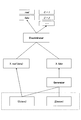
- FIG. 3 is a diagram showing a functional block of the image analysis device 102 according to the embodiment of the present invention.
- the image analysis device 102 can include an object image acquisition unit 301, a particle image extraction unit 302, a shape determination unit 303, a pseudo image generation unit 304, a similarity determination unit 305, and a pass / fail determination unit 306. Further, the image analysis device 102 can be used as an object image acquisition unit 301, a particle image extraction unit 302, a shape determination unit 303, a pseudo image generation unit 304, a similarity determination unit 305, and a pass / fail determination unit 306 by executing a program. Can function. Each will be described below.
- the object image acquisition unit 301 acquires an image of the object taken by the optical microscope 101 from the optical microscope 101. Further, the object image acquisition unit 301 stores the acquired image of the object in the storage device so that the particle image extraction unit 302 can refer to it.
- the particle image extraction unit 302, the shape determination unit 303, the pseudo image generation unit 304, and the similarity determination unit 305 perform processing for determining whether or not, for example, aluminum oxide powder or the like satisfies a predetermined criterion.
- FIG. 4 is a diagram for explaining an outline of the image analysis process according to the embodiment of the present invention.
- the image shown in the upper part of FIG. 4 is an image of the object acquired by the object image acquisition unit 301 from the optical microscope 101.
- the image of the object includes an image of a plurality of particles.
- step 401 the particle image extraction unit 302 extracts an image of one or a plurality of superposed particles from the image of the object. Then, the shape determination unit 303 determines whether or not the shape of the particles included in the extracted particle image satisfies a predetermined criterion.
- a particle image of particles that meet the predetermined criteria hereinafter, also referred to as OK particles
- an OK image hereinafter, also referred to as an OK particle image
- particles that do not meet the predetermined criteria hereinafter, provisional NG particles.
- the particle image (also referred to as a provisional NG image) is referred to as a provisional NG image (hereinafter, also referred to as a provisional NG image) (hereinafter, also referred to as a provisional NG particle image). That is, the shape of each particle of the particle image extracted from the image of the object is determined, and an OK image and a provisional NG image are obtained.
- an image with an unclear outline also referred to as an edge-missing image
- This unclear outline image can be treated in the same manner as an image with a clear outline when the same image can be reproduced by performing processing such as removing a part of the outline of the image with a clear outline. That is, even if the image has an unclear outline as a particle, for an image that can reproduce the same image from the image with a clear outline, it is determined whether or not the above-mentioned predetermined criteria are satisfied, and an OK image or a provisional NG image. Can be treated as.
- step 402 the pseudo image generation unit 304 superimposes a plurality of particle images including the OK image obtained in S401 to generate a superposed image (hereinafter referred to as "pseudo image").
- the pseudo image generation unit 304 may generate a pseudo image by superimposing a plurality of particle images including at least one OK image obtained in S401. Further, the particle image used for generating the pseudo image may include a plurality of OK images and may include a provisional NG image.
- a provisional NG image used for generating the pseudo image a provisional NG image extracted from the object image may be used, and another object image for the same powder (for example, oxidation in which quality inspection is performed). An image of an aluminum oxide powder different from the aluminum powder, or a provisional NG image extracted from another image of the aluminum oxide powder undergoing quality inspection) may be used. Further, a provisional NG image that is officially determined to be an NG image as a result of performing the analogy determination described later for another object image of the same powder may be used.
- step 403 the similarity determination unit 305 determines whether or not the provisional NG image extracted in S401 and the pseudo image generated in S402 are similar. Then, the similarity determination unit 305 considers that the provisional NG particles include OK particles when the two are similar (that is, particles satisfying a predetermined standard are included in an overlapping or agglomerated manner). If they are not similar, the provisional NG image is officially regarded as an NG image. That is, it is determined that the provisional NG particles of the provisional NG image determined to be similar to the pseudo image include the same number of OK particles as the number of OK images used to generate the similar pseudo image.
- the particle image extraction unit 302 extracts the image of the particles from the image of the object acquired by the object image acquisition unit 301. Further, the particle image extraction unit 302 stores the image of the extracted particles in the storage device so that the shape determination unit 303 can refer to it.
- the shape determination unit 303 determines whether or not the shape of the particles included in the image of the particles extracted by the particle image extraction unit 302 satisfies a predetermined criterion. For example, when the roundness of the particles is equal to or greater than the threshold value, the shape determination unit 303 can determine that the image including the particles is an OK image.
- the roundness means "the magnitude of deviation from a geometrically correct circle of a circular shape" as defined in JIS B0621-1984 "Definition and display of geometric deviation". Further, for example, when the roundness of the particles is lower than the threshold value, the shape determination unit 303 determines that the image including the particles is a provisional NG image.
- the criteria for the shape of the particles are not limited to roundness, but may include cases where the shape of the particles is an ellipse, etc. A reference composed of features such as length or perimeter of particles may be used.
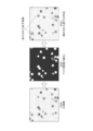
- FIG. 5 is a diagram for explaining particle image extraction and shape determination according to an embodiment of the present invention.
- the object image acquisition unit 301 acquires an image of the object (an image that is the basis of image analysis) as shown in FIG. 5 from the optical microscope 101.
- the particle image extraction unit 302 extracts an image of the particles. For example, the particle image extraction unit 302 binarizes the original image of S501 and masks an image as shown in FIG. 5 (in FIG. 5, the particle region is shown in white and the non-particle region is shown in black). To generate. Then, the particle image extraction unit 302 extracts (also referred to as crop or crop) an image of particles having no other particles in the periphery from the original image of S501 based on the mask image.
- the shape determination unit 303 determines whether or not the particles included in the image of the particles extracted in S502 satisfy a predetermined criterion.
- the pseudo image generation unit 304 generates an image (that is, a pseudo image) in which a plurality of particle images are superimposed and superimposed.
- the pseudo image is generated by superimposing an image containing an image of two or more particles. That is, the pseudo image may be generated using an image of two particles, or may be generated using an image of three or more particles. Moreover, the pseudo image may be generated using at least one OK image. That is, the pseudo image may be generated using only the OK image, or may be generated using the OK image and an image other than the OK image (for example, a provisional NG image).
- provisional NG image used for generating the pseudo image a provisional NG image extracted from the object image may be used, or a provisional NG image extracted from another object image for the same powder may be used. Good. Further, a provisional NG image that is officially regarded as an NG image may be used as a result of performing the analogy determination described later for another object image of the same powder.
- FIG. 6 is a diagram for explaining pseudo image generation according to an embodiment of the present invention.
- the pseudo image generation unit 304 randomly selects an image of particles used to generate a pseudo image.
- the pseudo image generation unit 304 may select an image of two or more particles including at least one OK image from an OK image and an image other than the OK image (for example, a provisional NG image). it can.
- the pseudo image generation unit 304 corrects the positions of the images of the two or more selected particles.
- the pseudo image generation unit 304 determines the positional relationship of the image of the particles so that the particles in the particle image come into contact with each other.
- the pseudo image generation unit 304 can generate various pseudo images by adjusting the place where the particles in the image of the particles come into contact with each other.
- the pseudo image generation unit 304 performs a process of superimposing the images of the particles whose position has been corrected in S601.
- the pseudo image generation unit 304 can generate various pseudo images by adjusting the degree of superimposition.
- the pseudo image generation unit 304 rotates the image group of the particles superimposed in S602.
- the pseudo image generation unit 304 can generate various pseudo images by adjusting the degree of rotation of the image group of the superimposed particles.
- the pseudo image generation unit 304 can generate various pseudo images by adjusting various parameters.
- the parameters are, for example, the number of particles, the place where the particles contact each other in the image of the particles, the degree of superposition, the degree of rotation of the image group of the superposed particles, or the circularity of the particles in the image. It may be any combination of color, transparency, degree of blur, and the like.
- the pseudo image generation unit 304 can also generate a pseudo image by using a method (also referred to as a Tetris (registered trademark) method) in which particles are dropped from one direction in the frame and stacked.
- the similarity determination unit 305 determines whether or not the provisional NG image determined by the shape determination unit 303 and the pseudo image generated by the pseudo image generation unit 304 are similar. Further, the similarity determination unit 305 determines that the provisional NG particles included in the provisional NG image include OK particles when the two are similar (that is, a plurality of particles including the OK particles overlap or aggregate). If they are not similar to each other, the provisional NG image is officially determined to be an image of NG particles.
- two examples of similarity judgment will be described.
- the similarity determination unit 305 compares the outer shape (contour) of the particles included in the superimposed particle image included in the pseudo image with the outer shape (contour) of the particles included in the provisional NG image. For example, the similarity determination unit 305 determines that when the difference between the outer shape of the particles included in the superimposed particle image included in the pseudo image and the outer shape of the particles included in the provisional NG image is equal to or less than the threshold value, both are used. Judge that they are similar.
- the similarity determination unit 305 uses both. Judge that they are not similar.
- the similarity determination unit 305 can perform similarity determination based on the shading (density) of each pixel of the image in addition to or instead of the above ⁇ similarity determination based on the outer shape>. Specifically, the similarity determination unit 305 compares the density value of each pixel of the pseudo image with the density value of each pixel of the provisional NG image. For example, the similarity determination unit 305 determines that the difference between the density value of each pixel of the pseudo image and the density value of each pixel of the provisional NG image is equal to or less than the threshold value.
- the similarity determination unit 305 determines that the two are not similar when the difference between the density value of each pixel of the pseudo image and the density value of each pixel of the provisional NG image is larger than the threshold value. ..
- each particle image of the pseudo image and the provisional NG image to be compared has 32 ⁇ 32 or more pixels, and 64 ⁇ 64 or more pixels. Is preferable.
- the pass / fail determination unit 306 determines whether or not the powder or the like containing the target particles has passed (that is, the result of the quality inspection). Specifically, the pass / fail determination unit 306 is included in the number of OK particles determined to be an OK image by the shape determination unit 303 and the provisional NG image determined to be similar to the pseudo image by the similarity determination unit 305. The number of OK particles that have been used is measured, and the obtained measured value is used for determination.
- the above-mentioned object is such that the number of images of particles extracted from the image of the object is preferably 100 or more, more preferably 500 or more, and further preferably 1,000 or more.
- a pass / fail judgment can be made after repeating and accumulating a series of steps from taking an image of an object to determining the analogy.
- the pass / fail determination unit 306 determines to the user terminal 103 that the total number of OK particles (number value 1) determined to be an OK image by the shape determination unit 303 and that the similarity determination unit 305 is similar to the pseudo image.
- the total number of OK particles included in the provisional NG image (number value 2) and the total number of NG particles officially determined as NG images by the similarity determination unit 305 (number value 3).
- the volume of the particles can be obtained, and the shape determination unit 303 determines that the image is OK. It is also possible to notify the 50% cumulative volume particle diameter (D 50 ) as the cumulative distribution of the volumes of the particles and the OK particles contained in the provisional NG image determined by the similarity determination unit 305 to be similar to the pseudo image. ..
- the pass / fail determination unit 306 is included in the total number of OK particles (number value 1) determined by the shape determination unit 303 to be an OK image, and in the provisional NG image determined by the similarity determination unit 305 to be similar to the pseudo image.
- the number value 1 is relative to the total number of OK particles (number value 2) and the total number of NG particles officially determined to be NG images by the similarity determination unit 305 (number value 3).
- the pass / fail determination unit 306 notifies the user terminal 103 that the powder or the like containing the object has passed.
- the predetermined numerical value to be passed is preferably 95%, more preferably 97%, and preferably 99%.
- FIG. 7 is a flowchart showing the flow of image analysis processing according to the embodiment of the present invention.
- step 700 the particle image extraction unit 302 extracts an image of the particles and creates an image of the extracted particles.
- the above-mentioned processing such as cropping can be performed.
- step 701 the shape determination unit 303 sets a reference (for example, a threshold value) to be satisfied by the particles included in the image of the particles.
- a reference for example, a threshold value
- the shape determination unit 303 can set a reference specified by the user terminal 103.
- step 702 the shape determination unit 303 determines whether or not the image of the particles extracted in S700 satisfies the criteria set in S701. If it is determined that the image does not meet the predetermined criteria (that is, it is a provisional NG image), the step 703 is performed. If it is determined that the predetermined criteria are satisfied (that is, the image is OK), the step is performed. Proceed to 707.
- the shape determination unit 303 has an image having an unclear outline as a particle, the above-mentioned determination about the unclear outline image can be further performed.
- step 707 the shape determination unit 303 notifies the pass / fail determination unit 306 of the number of OK images.
- step 703 the pseudo image generation unit 304 generates a pseudo image.
- the pseudo image generation unit 304 may generate a pseudo image each time the quality inspection is performed, or the pseudo image is the same as the already generated pseudo image (that is, the object for which the quality inspection is to be performed).
- a pseudo image) generated by using an OK image of a substance may be used.
- step 704 the similarity determination unit 305 determines the similarity between the provisional NG image determined in S702 and the pseudo image of S703. If they are not similar, the process proceeds to step 705, and if they are similar, the process proceeds to step 708.
- step 708 the similarity determination unit 305 notifies the pass / fail determination unit 306 of the number of OK particles contained in the provisional NG image determined to be similar to the pseudo image.
- step 705 the similarity determination unit 305 officially determines that the provisional NG image is an NG image.
- the pass / fail determination unit 306 is notified of the number of NG particles that are officially determined to be NG images.
- step 706 the pass / fail determination unit 306 determines the number of OK particles determined to be an OK image in S702 and the OK particles included in the provisional NG image determined to be similar to the pseudo image in S708.
- the number that is, the number of OK particles contained in the pseudo image determined to be similar in S704 and the number of NG particles officially determined to be an NG image in S705 are measured.
- the provisional NG particles determined to be similar to the pseudo image generated by using the OK image are OK particles. It is determined that one or more are included. Therefore, among the images of particles that have been determined not to meet the predetermined criteria in the conventional image analysis, the images of the particle group in which the particles satisfying the predetermined criteria are merely overlapped or aggregated are OK particle images. Can be treated as.
- a pseudo image is generated using the generation model.
- the generative model is a method of learning training data and generating new data similar to those data, and training is performed so that the distribution of the training data used for training and the distribution of the generated data match. It is a model to do.
- the generative model there are two types, for example, a hostile generation network (Generative Adversarial Networks (GAN)) and a variational autoencoder (VAE).
- GAN Geneative Adversarial Networks
- VAE variational autoencoder
- GAN hostile generation network
- FIGS. 8 and 9 are diagrams for explaining a GAN according to an embodiment of the present invention.
- a pseudo image (fake) (X fake) is generated by inputting input noise (Z (noise), for example, a random number) and class information (C (class)) of the input image into the generation network (Generator).
- Z noise
- C class information
- the pseudo image (fake) and the real data (X real (data)) are compared, and the class is discriminated together with the authenticity (real or fake) of the pseudo image (fake).
- FIG. 9 shows the process of deconvolution ("deconv") in which a pseudo image (fake) is generated by upsampling a feature amount in a generation network (Generator).
- 100 in the figure is an example of the feature amount, and corresponds to the sum of C (class) and Z (noise) in the configuration of GAN in FIG.
- a pre-stage network in which the input layer is an image of an object (that is, input data including an OK image and a provisional NG image) and the output layer is a feature quantity and a pre-stage network in which the input layer is a pre-stage network.
- Machine learning is performed using a network composed of a post-stage network in which the output layer is a pseudo image generated in the first embodiment, which is the feature amount output in 1., And the feature amount is extracted.
- GAN is used to generate a pseudo image (fake) using the provisional NG image to be judged as real data.
- various pseudo images are generated by the generation network (Generator) adjusting the feature amount (feature amount extracted in FIG. 10).
- the generation network (Generator) is the same as the above-mentioned post-stage network in which the feature amount is input and the pseudo image is output.
- the identification network (Disciminator) compares the generated pseudo image (fake) with the real data (genuine) (that is, the provisional NG image used as the real data) to identify whether it is genuine or fake.
- the generation network learns to deceive the identification network, and the identification network learns to identify more accurately, so that as the learning progresses, the generation network will generate pseudo-images (fake) that are closer to the real data. Become.
- the above-mentioned feature amount is extracted by using a plurality of extracted particle images including OK images as input data. More specifically, the above-mentioned feature amount is extracted by using a plurality of extracted particle images including an OK image and not a provisional NG image to be compared and not included as input data, and a pseudo image (fake). The number of OK images used for generation is obtained as additional information. Then, the generation network generates a pseudo image (counterfeit) using the provisional NG image to be analogized as the real data. As a result of learning by GAN, a pseudo image (fake) judged to be similar to the provisional NG image is generated. For the provisional NG image to be judged by analogy, the number of OK particles included in the provisional NG image can be obtained by referring to the additional information of the generated pseudo image (fake).
- the image of the object may include an image with an unclear outline (also referred to as an edge-missing image) as a particle or an image with an unclear outline (also referred to as an image containing noise) due to the inclusion of noise in the pixels.
- an unclear outline also referred to as an edge-missing image
- an unclear outline also referred to as an image containing noise
- VAE variational auto-encoder
- a plurality of particle images including OK images are input, the superimposed image on the input layer side is used as input data, and the provisional NG image is used as data similar to the input data to generate a pseudo image.
- the extracted particle image including the OK image and not including the provisional NG image to be compared is input, and the image superimposed on the input layer side is used as the input data, and the average vector and the variance vector are generated.
- Latent variables are stochastically extracted based on these, and a plurality of pseudo images similar to the provisional NG image to be compared are generated using the extracted latent variables, and the OK image used to generate the pseudo image is generated.
- the number of each is obtained as additional information.
- the pseudo image determined to be similar to the provisional NG image to be analogized the number of OK particles included in the provisional NG image can be obtained by referring to the additional information of the generated pseudo image.
- a pseudo image can be generated for the above-mentioned unclear image by using the OK image as input data and the unclear image as output data similar to the input data.
- a pseudo image determined to be similar to the target unclear image can be treated as an OK image.
Landscapes
- Engineering & Computer Science (AREA)
- Physics & Mathematics (AREA)
- General Physics & Mathematics (AREA)
- Theoretical Computer Science (AREA)
- Computer Vision & Pattern Recognition (AREA)
- Health & Medical Sciences (AREA)
- General Health & Medical Sciences (AREA)
- Chemical & Material Sciences (AREA)
- Life Sciences & Earth Sciences (AREA)
- Multimedia (AREA)
- Biochemistry (AREA)
- Pathology (AREA)
- Immunology (AREA)
- Analytical Chemistry (AREA)
- Dispersion Chemistry (AREA)
- Databases & Information Systems (AREA)
- Artificial Intelligence (AREA)
- Computing Systems (AREA)
- Evolutionary Computation (AREA)
- Medical Informatics (AREA)
- Software Systems (AREA)
- Quality & Reliability (AREA)
- Signal Processing (AREA)
- Biomedical Technology (AREA)
- Molecular Biology (AREA)
- Geometry (AREA)
- Image Analysis (AREA)
Priority Applications (4)
| Application Number | Priority Date | Filing Date | Title |
|---|---|---|---|
| JP2021522720A JP7038259B2 (ja) | 2019-05-27 | 2020-04-24 | 画像解析装置、方法、およびプログラム |
| CN202080038727.2A CN113892020B (zh) | 2019-05-27 | 2020-04-24 | 图像分析装置、方法、以及存储介质 |
| US17/595,608 US11995816B2 (en) | 2019-05-27 | 2020-04-24 | Image analysis apparatus, method, and program |
| US18/644,586 US12423804B2 (en) | 2019-05-27 | 2024-04-24 | Image analysis apparatus and method for determining shape of particle included in image of object |
Applications Claiming Priority (2)
| Application Number | Priority Date | Filing Date | Title |
|---|---|---|---|
| JP2019098384 | 2019-05-27 | ||
| JP2019-098384 | 2019-05-27 |
Related Child Applications (2)
| Application Number | Title | Priority Date | Filing Date |
|---|---|---|---|
| US17/595,608 A-371-Of-International US11995816B2 (en) | 2019-05-27 | 2020-04-24 | Image analysis apparatus, method, and program |
| US18/644,586 Division US12423804B2 (en) | 2019-05-27 | 2024-04-24 | Image analysis apparatus and method for determining shape of particle included in image of object |
Publications (1)
| Publication Number | Publication Date |
|---|---|
| WO2020241142A1 true WO2020241142A1 (ja) | 2020-12-03 |
Family
ID=73554012
Family Applications (1)
| Application Number | Title | Priority Date | Filing Date |
|---|---|---|---|
| PCT/JP2020/017799 Ceased WO2020241142A1 (ja) | 2019-05-27 | 2020-04-24 | 画像解析装置、方法、およびプログラム |
Country Status (4)
| Country | Link |
|---|---|
| US (2) | US11995816B2 (https=) |
| JP (1) | JP7038259B2 (https=) |
| CN (1) | CN113892020B (https=) |
| WO (1) | WO2020241142A1 (https=) |
Cited By (1)
| Publication number | Priority date | Publication date | Assignee | Title |
|---|---|---|---|---|
| WO2023149513A1 (ja) * | 2022-02-05 | 2023-08-10 | 国立大学法人 東京大学 | 偽造画像検出装置、偽造画像検出方法、及びプログラム |
Families Citing this family (4)
| Publication number | Priority date | Publication date | Assignee | Title |
|---|---|---|---|---|
| GB201718756D0 (en) * | 2017-11-13 | 2017-12-27 | Cambridge Bio-Augmentation Systems Ltd | Neural interface |
| US20220108434A1 (en) * | 2020-10-07 | 2022-04-07 | National Technology & Engineering Solutions Of Sandia, Llc | Deep learning for defect detection in high-reliability components |
| KR102785966B1 (ko) * | 2022-03-18 | 2025-03-26 | 주식회사 뉴로메카 | 딥 러닝 알고리즘을 이용한 이미지 기반의 미세유체 세포 분류기 및 미세유체 세포 분류 방법 |
| CN118980682B (zh) * | 2024-10-21 | 2025-02-28 | 山东辛诚材料科技有限公司 | 一种基于图像识别的猫砂质检方法及系统 |
Citations (5)
| Publication number | Priority date | Publication date | Assignee | Title |
|---|---|---|---|---|
| JPS6052741A (ja) * | 1983-09-01 | 1985-03-26 | Mitsubishi Rayon Co Ltd | 粒子径分布測定方法 |
| JPH0735696A (ja) * | 1993-07-23 | 1995-02-07 | Sharp Corp | 粒子凝集検出除去装置 |
| JP2010117175A (ja) * | 2008-11-11 | 2010-05-27 | National Institute Of Advanced Industrial Science & Technology | 画像処理システム、画像処理方法、プログラムおよび記録媒体 |
| WO2017051327A1 (en) * | 2015-09-22 | 2017-03-30 | Imageprovision Technology Pvt. Ltd. | Method and system for detection and classification of particles based on processing of microphotographic images |
| US20190096056A1 (en) * | 2017-09-25 | 2019-03-28 | United Technologies Corporation | Automated material characterization system including conditional generative adversarial networks |
Family Cites Families (12)
| Publication number | Priority date | Publication date | Assignee | Title |
|---|---|---|---|---|
| JP2790101B2 (ja) * | 1995-11-27 | 1998-08-27 | 東レ株式会社 | 粒子凝集パターン判定装置 |
| JP3003925B2 (ja) * | 1996-12-02 | 2000-01-31 | 株式会社日立製作所 | 欠陥検査装置 |
| JP5586889B2 (ja) * | 2009-07-29 | 2014-09-10 | 株式会社日立ハイテクノロジーズ | 粒子画像解析装置 |
| CN102494987A (zh) * | 2011-12-13 | 2012-06-13 | 天津卓朗科技发展有限公司 | 球墨铸铁中显微粒子的自动分类评级方法 |
| US10657672B2 (en) * | 2015-09-30 | 2020-05-19 | Nec Corporation | Image processing device, image processing method and storage medium |
| CN106203456B (zh) * | 2016-07-20 | 2018-01-02 | 西安科技大学 | 基于改进差分进化粒子群算法的煤尘重叠颗粒分离方法 |
| EP3293672A1 (en) * | 2016-09-07 | 2018-03-14 | Malvern Panalytical Limited | Particle boundary identification |
| JP6448065B2 (ja) * | 2017-01-17 | 2019-01-09 | みずほ情報総研株式会社 | 画像処理システム、画像処理方法及び画像処理プログラム |
| KR102481885B1 (ko) * | 2017-09-08 | 2022-12-28 | 삼성전자주식회사 | 클래스 인식을 위한 뉴럴 네트워크 학습 방법 및 디바이스 |
| WO2019053770A1 (en) * | 2017-09-12 | 2019-03-21 | Nec Corporation | IMAGE PROCESSING DEVICE, IMAGE PROCESSING METHOD, AND INFORMATION MEDIUM |
| CN108921782B (zh) * | 2018-05-17 | 2023-04-14 | 腾讯科技(深圳)有限公司 | 一种图像处理方法、装置及存储介质 |
| EP3859304B1 (en) * | 2018-09-27 | 2024-09-18 | HORIBA, Ltd. | Method for generating data for particle analysis, program for generating data for particle analysis, and device for generating data for particle analysis |
-
2020
- 2020-04-24 JP JP2021522720A patent/JP7038259B2/ja active Active
- 2020-04-24 CN CN202080038727.2A patent/CN113892020B/zh active Active
- 2020-04-24 WO PCT/JP2020/017799 patent/WO2020241142A1/ja not_active Ceased
- 2020-04-24 US US17/595,608 patent/US11995816B2/en active Active
-
2024
- 2024-04-24 US US18/644,586 patent/US12423804B2/en active Active
Patent Citations (5)
| Publication number | Priority date | Publication date | Assignee | Title |
|---|---|---|---|---|
| JPS6052741A (ja) * | 1983-09-01 | 1985-03-26 | Mitsubishi Rayon Co Ltd | 粒子径分布測定方法 |
| JPH0735696A (ja) * | 1993-07-23 | 1995-02-07 | Sharp Corp | 粒子凝集検出除去装置 |
| JP2010117175A (ja) * | 2008-11-11 | 2010-05-27 | National Institute Of Advanced Industrial Science & Technology | 画像処理システム、画像処理方法、プログラムおよび記録媒体 |
| WO2017051327A1 (en) * | 2015-09-22 | 2017-03-30 | Imageprovision Technology Pvt. Ltd. | Method and system for detection and classification of particles based on processing of microphotographic images |
| US20190096056A1 (en) * | 2017-09-25 | 2019-03-28 | United Technologies Corporation | Automated material characterization system including conditional generative adversarial networks |
Cited By (1)
| Publication number | Priority date | Publication date | Assignee | Title |
|---|---|---|---|---|
| WO2023149513A1 (ja) * | 2022-02-05 | 2023-08-10 | 国立大学法人 東京大学 | 偽造画像検出装置、偽造画像検出方法、及びプログラム |
Also Published As
| Publication number | Publication date |
|---|---|
| US20220327675A1 (en) | 2022-10-13 |
| US20240273711A1 (en) | 2024-08-15 |
| US11995816B2 (en) | 2024-05-28 |
| US12423804B2 (en) | 2025-09-23 |
| CN113892020B (zh) | 2025-05-13 |
| JPWO2020241142A1 (https=) | 2020-12-03 |
| CN113892020A (zh) | 2022-01-04 |
| JP7038259B2 (ja) | 2022-03-17 |
Similar Documents
| Publication | Publication Date | Title |
|---|---|---|
| JP7038259B2 (ja) | 画像解析装置、方法、およびプログラム | |
| Scherhag et al. | Detection of face morphing attacks based on PRNU analysis | |
| JPWO2004051575A1 (ja) | 特徴領域抽出装置、特徴領域抽出方法および特徴領域抽出プログラム | |
| CN112241929B (zh) | 水印嵌入及水印检测方法、装置及电子设备 | |
| CN113792789B (zh) | 基于类激活热力图的图像篡改检测与定位的方法及系统 | |
| CN115116108A (zh) | 基于双流对比学习模型的人脸篡改视频检测方法及系统 | |
| Sharma | A survey of image forensics: Exploring forgery detection in image colorization | |
| Jijina et al. | Detection of recoloring and copy-move forgery in digital images | |
| Conti et al. | Do not deceive your employer with a virtual background: A video conferencing manipulation-detection system | |
| US20250173993A1 (en) | System and method for real time optical illusion photography | |
| Mayer et al. | Countering anti-forensics of lateral chromatic aberration | |
| CN119579915A (zh) | 一种屏幕翻拍识别方法、装置以及设备 | |
| Bhowal et al. | Multi-approach survey and in-depth analysis of image forgery detection techniques: A. Bhowal et al. | |
| CN120375168A (zh) | 基于混合模态的深度伪造人像检测方法及相关设备 | |
| Nataraj et al. | Holistic image manipulation detection using pixel co-occurrence matrices | |
| CN114170470B (zh) | 样本生成方法、装置、设备和存储介质 | |
| Hwang et al. | Identification method for digital image forgery and filtering region through interpolation | |
| Rao et al. | TruceNet: a CNN-based model for accurate classification of DeepFake images | |
| Biju et al. | Enhancing image forgery detection with multi-modal deep learning and statistical methods | |
| CN120881213B (zh) | 面向图像数据个性隐私保护的安全分析方法及设备 | |
| JP2005250771A (ja) | 対象物識別装置および方法並びにプログラム | |
| JP2005250772A (ja) | 対象物識別装置および方法、学習方法並びにプログラム | |
| CN120953652A (zh) | 证件分类方法、电子设备及计算机程序产品 | |
| Abraham et al. | State-of-the-Art Techniques for Image Forgery Detection: A Review | |
| Lin et al. | Image provenance inference through content-based device fingerprint analysis |
Legal Events
| Date | Code | Title | Description |
|---|---|---|---|
| 121 | Ep: the epo has been informed by wipo that ep was designated in this application |
Ref document number: 20813896 Country of ref document: EP Kind code of ref document: A1 |
|
| ENP | Entry into the national phase |
Ref document number: 2021522720 Country of ref document: JP Kind code of ref document: A |
|
| NENP | Non-entry into the national phase |
Ref country code: DE |
|
| 122 | Ep: pct application non-entry in european phase |
Ref document number: 20813896 Country of ref document: EP Kind code of ref document: A1 |
|
| WWG | Wipo information: grant in national office |
Ref document number: 202080038727.2 Country of ref document: CN |