WO2020240943A1 - Flat harness attachment structure, flat harness attachment component, and flat harness with attachment component - Google Patents
Flat harness attachment structure, flat harness attachment component, and flat harness with attachment component Download PDFInfo
- Publication number
- WO2020240943A1 WO2020240943A1 PCT/JP2020/005692 JP2020005692W WO2020240943A1 WO 2020240943 A1 WO2020240943 A1 WO 2020240943A1 JP 2020005692 W JP2020005692 W JP 2020005692W WO 2020240943 A1 WO2020240943 A1 WO 2020240943A1
- Authority
- WO
- WIPO (PCT)
- Prior art keywords
- flat harness
- mounting
- plate
- flat
- fixing
- Prior art date
Links
- 238000003825 pressing Methods 0.000 claims abstract description 38
- 239000000463 material Substances 0.000 description 6
- 230000002093 peripheral effect Effects 0.000 description 4
- 238000003466 welding Methods 0.000 description 4
- 210000000078 claw Anatomy 0.000 description 3
- 239000004020 conductor Substances 0.000 description 3
- 239000002184 metal Substances 0.000 description 3
- 230000004048 modification Effects 0.000 description 3
- 238000012986 modification Methods 0.000 description 3
- 230000000149 penetrating effect Effects 0.000 description 3
- 239000011347 resin Substances 0.000 description 3
- 229920005989 resin Polymers 0.000 description 3
- 239000011248 coating agent Substances 0.000 description 2
- 238000000576 coating method Methods 0.000 description 2
- 238000005520 cutting process Methods 0.000 description 1
- 210000003298 dental enamel Anatomy 0.000 description 1
- 230000005489 elastic deformation Effects 0.000 description 1
- 230000005611 electricity Effects 0.000 description 1
- 238000009413 insulation Methods 0.000 description 1
- 238000004519 manufacturing process Methods 0.000 description 1
- 238000000465 moulding Methods 0.000 description 1
- 229910001120 nichrome Inorganic materials 0.000 description 1
- 239000013307 optical fiber Substances 0.000 description 1
- 230000003584 silencer Effects 0.000 description 1
Images


Classifications
-
- H—ELECTRICITY
- H02—GENERATION; CONVERSION OR DISTRIBUTION OF ELECTRIC POWER
- H02G—INSTALLATION OF ELECTRIC CABLES OR LINES, OR OF COMBINED OPTICAL AND ELECTRIC CABLES OR LINES
- H02G3/00—Installations of electric cables or lines or protective tubing therefor in or on buildings, equivalent structures or vehicles
- H02G3/30—Installations of cables or lines on walls, floors or ceilings
- H02G3/32—Installations of cables or lines on walls, floors or ceilings using mounting clamps
-
- B—PERFORMING OPERATIONS; TRANSPORTING
- B60—VEHICLES IN GENERAL
- B60R—VEHICLES, VEHICLE FITTINGS, OR VEHICLE PARTS, NOT OTHERWISE PROVIDED FOR
- B60R16/00—Electric or fluid circuits specially adapted for vehicles and not otherwise provided for; Arrangement of elements of electric or fluid circuits specially adapted for vehicles and not otherwise provided for
- B60R16/02—Electric or fluid circuits specially adapted for vehicles and not otherwise provided for; Arrangement of elements of electric or fluid circuits specially adapted for vehicles and not otherwise provided for electric constitutive elements
- B60R16/0207—Wire harnesses
- B60R16/0215—Protecting, fastening and routing means therefor
-
- F—MECHANICAL ENGINEERING; LIGHTING; HEATING; WEAPONS; BLASTING
- F16—ENGINEERING ELEMENTS AND UNITS; GENERAL MEASURES FOR PRODUCING AND MAINTAINING EFFECTIVE FUNCTIONING OF MACHINES OR INSTALLATIONS; THERMAL INSULATION IN GENERAL
- F16B—DEVICES FOR FASTENING OR SECURING CONSTRUCTIONAL ELEMENTS OR MACHINE PARTS TOGETHER, e.g. NAILS, BOLTS, CIRCLIPS, CLAMPS, CLIPS OR WEDGES; JOINTS OR JOINTING
- F16B2/00—Friction-grip releasable fastenings
- F16B2/02—Clamps, i.e. with gripping action effected by positive means other than the inherent resistance to deformation of the material of the fastening
- F16B2/06—Clamps, i.e. with gripping action effected by positive means other than the inherent resistance to deformation of the material of the fastening external, i.e. with contracting action
- F16B2/12—Clamps, i.e. with gripping action effected by positive means other than the inherent resistance to deformation of the material of the fastening external, i.e. with contracting action using sliding jaws
-
- H—ELECTRICITY
- H01—ELECTRIC ELEMENTS
- H01B—CABLES; CONDUCTORS; INSULATORS; SELECTION OF MATERIALS FOR THEIR CONDUCTIVE, INSULATING OR DIELECTRIC PROPERTIES
- H01B7/00—Insulated conductors or cables characterised by their form
- H01B7/08—Flat or ribbon cables
- H01B7/0823—Parallel wires, incorporated in a flat insulating profile
-
- H—ELECTRICITY
- H02—GENERATION; CONVERSION OR DISTRIBUTION OF ELECTRIC POWER
- H02G—INSTALLATION OF ELECTRIC CABLES OR LINES, OR OF COMBINED OPTICAL AND ELECTRIC CABLES OR LINES
- H02G3/00—Installations of electric cables or lines or protective tubing therefor in or on buildings, equivalent structures or vehicles
- H02G3/02—Details
- H02G3/04—Protective tubing or conduits, e.g. cable ladders or cable troughs
- H02G3/0406—Details thereof
-
- H—ELECTRICITY
- H01—ELECTRIC ELEMENTS
- H01B—CABLES; CONDUCTORS; INSULATORS; SELECTION OF MATERIALS FOR THEIR CONDUCTIVE, INSULATING OR DIELECTRIC PROPERTIES
- H01B7/00—Insulated conductors or cables characterised by their form
- H01B7/08—Flat or ribbon cables
- H01B7/0838—Parallel wires, sandwiched between two insulating layers
Definitions
- This disclosure relates to a flat harness mounting structure, a flat harness mounting component, and a flat harness with mounting components.
- Patent Document 1 discloses a structure in which a flat wiring material is arranged on the back surface of a panel. A wiring groove is formed in the panel. The flat wiring material is arranged in the arrangement groove.
- the clip has a pair of fixing claws, and the panel is formed with a hole into which the pair of fixing claws are inserted. A pair of fixing claws are inserted into the pair of holes with the clip straddling the wiring flat wiring material in the width direction. As a result, the flat wiring material is fixed to the panel.
- the purpose of this disclosure is to enable flat harnesses of various widths to be attached to the attachment target portion.
- the flat harness mounting structure of the present disclosure is a flat harness mounting structure for a mounting target member having a mounting target surface, and is a side portion of either a flat harness arranged on the mounting target surface or the flat harness.
- a flat harness mounting structure including a fixing portion fixed to the mounting target member on the side and a pressing portion extending from the fixing portion onto the flat harness so as to press the flat harness against the mounting target surface. Is.
- the flat harness mounting component of the present disclosure includes a fixing portion fixed to a member to be mounted and a pressing portion extending from the fixing portion with a base end portion connected to the fixing portion, and the pressing portion includes the pressing portion.
- a flat harness mounting component including a gap forming portion that faces away from the mounting target member and a main body portion that extends along the mounting target surface of the mounting target member.
- the flat harness with mounting components of the present disclosure includes a flat harness and mounting components including a fixing portion and a pressing portion, the fixing portion is a portion that can be fixed to a member to be mounted, and the fixing portion is A flat harness with mounting parts that penetrates one side of the flat harness and extends from the fixed portion to the flat harness side.
- flat harnesses of various widths are attached to the attachment target portion.
- FIG. 1 is a plan view showing a flat harness mounting structure according to an embodiment.
- FIG. 2 is a sectional view taken along line II-II of FIG.
- FIG. 3 is a cross-sectional view showing a flat harness mounting component according to a modified example.
- FIG. 4 is a cross-sectional view showing a flat harness mounting component according to a modified example.
- FIG. 5 is a partial plan view showing a flat harness mounting component according to a modified example.
- FIG. 6 is a partial plan view showing a flat harness mounting component according to a modified example.
- FIG. 7 is a cross-sectional view showing a flat harness mounting component according to a modified example.
- FIG. 8 is a cross-sectional view showing a flat harness with mounting parts according to a modified example.
- the flat harness mounting structure of the present disclosure is as follows.
- a flat harness mounting structure for a mounting target member having a mounting target surface wherein the mounting target member is on one side of the flat harness arranged on the mounting target surface and the flat harness.
- It is a flat harness mounting structure including a fixed portion fixed to the flat harness and a pressing portion extending from the fixed portion onto the flat harness so as to press the flat harness against the mounting target surface.
- the fixing portion is fixed to the mounting target member on the side portion side of either one side of the flat harness.
- a plate-shaped portion extending from the fixed portion onto the flat harness presses the flat harness against the mounting surface. Therefore, regardless of the width of the flat harness, the plate-shaped portion presses the flat harness against the mounting target surface.
- flat harnesses of various widths are attached to the members to be attached.
- the pressing portion may be a plate-shaped portion formed in a flat plate shape.
- the flat harness can be pressed stably by the plate-shaped portion.
- the pressing portion may be integrally formed with the fixing portion.
- a hole through which the fixing portion penetrates is formed in the pressing portion, and the fixing portion may be fixed to the mounting target member in a state where the fixing portion penetrates the hole.
- the fixing portion is fixed to the member to be attached while being penetrated through the hole. Therefore, the union work of the plate-shaped portion and the fixing portion and the work of fixing the fixing portion to the attachment target member can be easily performed.
- the pressing portion may be set to a length extending from one side portion side to the other side portion with respect to the flat harness.
- the flat harness is pressed over the entire width direction.
- the flat harness mounting structure may include a plurality of sets of the fixing portion and the pressing portion.
- the flat harness can be attached to the member to be attached at a plurality of places.
- the plurality of sets of the fixing portion and the pressing portion may include those fixed to the attachment target member on different side portions with respect to the flat harness.
- the flat harness is pressed from different sides along the extending direction of the flat harness.
- a plurality of the pressing portions may extend from one fixing portion.
- the flat harness can be pressed by a plurality of pressing portions extending from one fixed portion.
- the plurality of pressing portions can press the bent portion, the branch portion, and the like of the flat harness.
- the flat harness mounting parts disclosed in this disclosure are as follows.
- a fixing portion fixed to the attachment target member and a pressing portion extending from the fixing portion with the base end portion connected to the fixing portion are provided, and the pressing portion is provided from the attachment target member.
- the pressing portion includes a gap forming portion and a main body portion.
- the gap forming portion faces in a direction away from the mounting target member. Therefore, a gap suitable for arranging the flat harness is formed between the main body and the mounting surface. According to this flat harness fixing component, the flat harness can be appropriately pressed against the mounting target surface by the main body portion.
- the flat harness with mounting parts disclosed in this disclosure is as follows.
- a flat harness and a mounting component including a fixing portion and a pressing portion are included, the fixing portion is a portion that can be fixed to a member to be mounted, and the fixing portion is one of the flat harnesses.
- the pressing portion is a flat harness with mounting parts that penetrates the side portion on the side and extends from the fixing portion to the flat harness side.
- the flat harness and mounting parts can be handled integrally. Therefore, when the flat harness is arranged on the member to be mounted, the mounting component can be easily fixed to the member to be mounted, and the flat harness can be easily mounted.
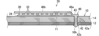
- FIG. 1 is a plan view showing a flat harness mounting structure 20.
- FIG. 2 is a sectional view taken along line II-II of FIG.
- the flat harness mounting structure 20 is a structure for mounting the flat harness 30 to the mounting target member 10 having the mounting target surface 11.
- the mounting target member 10 is, for example, a plate-shaped portion in a vehicle.
- the member 10 to be attached may be a flat plate-shaped portion or a bent plate-shaped portion.
- the mounting target member 10 includes a plate-shaped main body portion 12 and an elastic portion 14.
- the plate-shaped main body 12 is a metal body or the like in a vehicle.
- the elastic portion 14 is a plate-shaped portion having elasticity.
- the elastic portion 14 is, for example, a foamed resin, a non-woven material, or the like, and is considered to be a member that plays a role of a cushioning material, a silencer, or the like.
- the elastic portion 14 is superposed on one main surface of the plate-shaped main body portion 12.
- the attachment target member 10 is a laminated body in which the elastic portion 14 is laminated on the plate-shaped main body portion 12.
- the flat harness 30 is arranged on the outward surface of the member 10 to be mounted on the elastic portion 14 side. Therefore, the outward surface on the elastic portion 14 side of the mounting target member 10 is the mounting target surface 11. It is preferable that the mounting target member 10 is formed with a mounting hole 10h.
- One of the plate-shaped main body portion 12 and the elastic portion 14 may be omitted.
- the flat harness mounting structure 20 includes a flat harness 30, a fixing portion 42, and a plate-shaped portion 48 as a pressing portion.
- the flat harness 30 includes a plurality of linear wiring members and is formed in a flat shape as a whole.
- the flat harness 30 includes a plurality of electric wires 32 and a seat 34.
- the electric wire 32 is an example of a linear wiring member.
- the electric wire 32 includes a core wire and a coating.
- the core wire is a linear conductor formed of a conductive member such as metal.
- the coating is an insulating portion that surrounds the core wire.
- the linear wiring member may be any linear member that transmits electricity, light, or the like.
- the linear wiring member may be a bare wire, a shielded wire, a twisted wire, an enamel wire, a nichrome wire, an optical fiber, or the like, in addition to an electric wire.
- the sheet 34 is a sheet-like member that keeps a plurality of electric wires 32 in a flat shape.
- the sheet 34 is made of resin or the like.
- the sheet 34 may contain metal.
- the sheet 34 may include a non-woven sheet.
- a plurality of electric wires 32 are fixed in parallel on one main surface of the sheet 34.
- the electric wire 32 is fixed to the sheet 34 by welding, adhesion, adhesion, or the like.
- the welding may be ultrasonic welding or heat welding.
- the flat harness 30 may be branched according to the position of each electrical component to be connected.
- FIG. 1 shows an example in which some electric wires 32a of the plurality of electric wires 32 are branched outward.
- the sheet 34 may be formed so as to branch along the path of the electric wire 32.
- the portion of the flat harness 30 provided with the largest number of electric wires 32 may be referred to as a trunk line portion 30a in a later description. Further, the portion where the electric wire 32a is branched may be referred to later as a branch line portion 30b.
- the end of each electric wire 32 is connected to an electric component or the like via a connector or the like.
- a plurality of electric wires 32 may be laminated in a plurality of layers on the sheet 34.
- the flat harness 30 is not limited to the above example.
- the plurality of electric wires may be kept flat by a flat frame member or the like.
- a plurality of electric wires may be directly joined in a parallel form so as to have a flat form.
- the flat harness 30 may be maintained in a flat state in a state where a plurality of linear conductors are mutually insulated by an insulating member, such as FPC (Flexible printed circuits). That is, the flat harness may be a wiring member in which a plurality of linear conductors are held in a flat form in a state of being insulated from each other and formed to have a thickness smaller than a width as a whole.
- the flat harness 30 is arranged on the mounting target surface 11 in a posture parallel to the mounting target surface 11.
- the electric wire 32 is located on the side opposite to the mounting target surface 11 with respect to the seat 34.
- the electric wire 32 may be located on the mounting target surface 11 side with respect to the seat 34.
- the fixing portion 42 is a portion fixed to the mounting target member 10 on either side of the flat harness 30.
- the plate-shaped portion 48 is a portion extending from the fixing portion 42 onto the flat harness 30 so as to press the flat harness 30 against the mounting target surface 11.
- the plate-shaped portion 48 is integrally formed with the fixing portion 42. More specifically, the plate-shaped portion 48 and the fixing portion 42 are integrally formed with the mold by injecting the molten resin into the mold. Therefore, the plate-shaped portion 48 and the fixed portion 42 are integrally connected without a boundary surface.
- the one in which the fixing portion 42 and the plate-shaped portion 48 are integrally formed may be referred to as a flat harness mounting component 40.
- the pressing portion is a plate-shaped portion extending in a strip shape.
- the pressing portion may have a round bar shape, a square bar shape, a triangular bar shape, or the like.
- the fixing portion 42 is configured to be able to be fitted into the mounting hole 10h formed in the mounting target member 10 in a retaining state.
- the fixing portion 42 includes, for example, a long main body portion 42a and a hooking portion 42b.
- the long main body portion 42a is formed to have a length dimension that allows it to be inserted into the mounting hole 10h and reach the back surface side of the mounting target member 10.
- the hooking portion 42b is formed so as to project outward from the tip end portion of the long main body portion 42a, and is configured to be hookable from the back surface side of the mounting target member 10 to the peripheral edge portion of the mounting hole 10h.
- the hooking portion 42b can be elastically deformed from a protruding state in which it can be hooked on the peripheral edge of the mounting hole 10h to a retracted state in which it can pass through the mounting hole 10h, for example, by an elastic deformation structure utilizing a leaf spring shape or the like.
- an elastic deformation structure utilizing a leaf spring shape or the like.
- well-known configurations such as a harness clip, a harness clamp, a push rivet, and the like may be adopted.
- a head 43 extending outward is formed at the base end of the fixing portion 42.
- the head 43 is formed in a disk shape overhanging the entire circumferential direction of the base end portion of the fixing portion 42.
- the head 43 is caught on one side (mounting target surface 11 side) opening peripheral edge portion of the mounting hole 10h, and the hooked portion 42b is caught on the other side opening peripheral edge portion of the mounting hole 10h. Get caught in.
- the elastic portion 14 may be in a compressed state. In this case, the elastic restoring force of the elastic portion 14 causes the head 43 to be continuously pushed in the direction away from the plate-shaped main body portion 12. Therefore, the fixing portion 42 is less likely to be tilted, and the posture of the flat harness mounting component 40 is stabilized.
- the plate-shaped portion 48 extends outward from the base end portion of the fixing portion 42 away from the axial direction of the fixing portion 42.
- the base end portion of the plate-shaped portion 48 is connected to the base end portion of the fixing portion 42.
- the plate-shaped portion 48 includes a gap forming portion 48a and a main body portion 48b.
- the gap forming portion 48a is formed so as to face in a direction away from the attachment target member 10 from the portion connected to the base end portion of the fixing portion 42.
- the gap forming portion 48a is inclined so as to face outward from a part of the periphery of the head 43 and to face the opposite direction to the tip end portion of the fixing portion 42.
- the main body portion 48b extends from the tip end portion of the gap forming portion 48a along the mounting target surface 11.
- the main body portion 48b is formed in an elongated plate shape.
- the main body portion 48b extends from the tip end portion of the gap forming portion 48a in a direction away from the fixing portion 42 while being orthogonal to the axial direction of the fixing portion 42. Therefore, there may be a difference in the position of the inclination of the gap forming portion 48a between the inward surface of the head 43 and the inward surface of the main body 48b in the direction along the axial direction of the fixed portion 42. .. With the fixing portion 42 fixed to the mounting target member 10, the inward facing surface of the head 43 is in contact with the mounting target surface 11.
- a gap is formed between the main body portion 48b and the mounting target surface 11 according to the inclination of the gap forming portion 48a.
- the flat harness 30 is arranged in this gap.
- the gap is preferably smaller than the thickness dimension of the flat harness 30 (the thickness of the sheet 34 plus the diameter of the electric wire 32).
- the gap forming portion 48a does not have to be inclined with respect to the fixing portion 42, and may be formed in a crank shape.
- the thickness of the flat harness 30 to be attached can be changed depending on the diameter of the electric wire 32, the thickness of the sheet 34, and the like.
- the gap forming portion 48a may be configured according to the thickness of the flat harness 30 to be attached. For example, as shown in FIG. 3, when the thickness of the flat harness 30A is relatively small, the inclination of the gap forming portion 48a1 may be set to be small. As a result, the difference between the inward surface of the head 43 and the inward surface of the main body 48b becomes small in the direction along the axial direction of the fixed portion 42, and the flat harness 30A having a relatively small thickness can be pressed. A suitable configuration can be obtained. Further, for example, as shown in FIG.
- the inclination of the gap forming portion 48a2 may be set to be large.
- the difference between the inward surface of the head 43 and the inward surface of the main body 48b can be increased in the direction along the axial direction of the fixed portion 42, and the flat harness 30B having a relatively large thickness is pushed. It can be configured to be suitable for attachment.
- the length dimension of the plate-shaped portion 48 is preferably set to the length from one side portion of the flat harness 30 to the other side portion.
- the fixing portion 42 is fixed to the attachment target member 10 at a position outward from one side portion of the flat harness 30. Therefore, the length dimension of the plate-shaped portion 48 is preferably equal to or larger than the width dimension of the flat harness 30.
- the fixing portion 42 may penetrate the side portion inside the edge of one side portion of the flat harness 30. In this case, even if the length dimension of the plate-shaped portion 48 is less than the width dimension of the flat harness 30, the length dimension of the plate-shaped portion 48 extends from one side portion of the flat harness 30 to the other side portion. Can be set to length.
- the length dimension of the plate-shaped portion 48 may be set to the length before reaching from one side portion of the flat harness 30 to the other side portion.
- the plate-shaped portion 48 may be in an oblique posture with respect to the width direction of the flat harness 30.
- a plurality of sets including the fixed portion and the plate-shaped portion may be provided.
- the flat harness mounting component 40 including the fixing portion 42 and the plate-shaped portion 48 in addition to the flat harness mounting component 40 including the fixing portion 42 and the plate-shaped portion 48, the flat harness mounting parts 40A, 40B, 40C, 40D, and 40E are shown.
- the flat harness mounting component 40A is a component including a fixing portion 42 and a plate-shaped portion 48 similar to the flat harness mounting component 40. Focusing on the flat harness mounting parts 40 and 40A, the flat harness mounting part 40 and the flat harness mounting part 40A are fixed to the mounting target member 10 on different sides of the flat harness 30. Further, the flat harness mounting parts 40 and 40A are provided at different positions in the extending direction of the flat harness 30.
- the fixing portion 42 is fixed to the mounting target member 10 on one side side (here, the outside of the side portion) of the flat harness 30.
- the plate-shaped portion 48 crosses the flat harness 30 so as to face from one side portion of the flat harness 30 to the other side portion.
- the flat harness mounting component 40A is provided at a position adjacent to the flat harness mounting component 40 at intervals along the extending direction of the flat harness 30.
- the posture of the flat harness mounting component 40A is symmetrical with respect to the flat harness mounting component 40 with respect to the center line in the width direction of the flat harness 30. That is, the fixing portion 42 is fixed to the mounting target member 10 on the other side portion side (here, the outside of the side portion) of the flat harness 30.
- the plate-shaped portion 48 crosses the flat harness 30 so as to face one side from the other side of the flat harness 30.
- the plate-shaped portions 48 of the flat harness mounting parts 40 and 40A extend from different side portions of the flat harness 30 at different positions along the extending direction of the flat harness 30 to press the flat harness 30. .. It is considered that the flat harness mounting parts 40 and 40A can effectively press the flat harness 30 on the side close to the fixing portion 42. Therefore, the flat harness 30 is effectively pressed against the mounting target surface 11 over a certain range.
- the fixing portions 42 may be arranged alternately with respect to both side portions of the flat harness 30.
- the flat harness mounting part 40B includes a fixing portion 42 and a plate-shaped portion 48B.
- the fixing portion 42 has the same configuration as that described above.
- the plate-shaped portion 48B is formed wider than the plate-shaped portion 48.
- the flat harness 30 is protected by the plate-shaped portion 48B.
- the flat harness mounting component 40B may be provided.
- the width of the plate-shaped portion 48B can be appropriately set depending on the region where protection is desired.
- the plate-shaped portion 48B may be set wider than the width of the fixed portion 42.
- the width of the fixed portion 42 is a dimension in a direction orthogonal to both the axial direction of the fixed portion 42 and the extending direction of the plate-shaped portion 48B. Further, for example, the plate-shaped portion 48B may be set wider than the width of the flat harness 30.
- the flat harness mounting component 40C includes a fixing portion 42 and a plate-shaped portion 48C.
- the fixing portion 42 has the same configuration as that described above.
- the plate-shaped portion 48C is shorter than the plate-shaped portion 48.
- the flat harness mounting component 40D includes a fixing portion 42 and a plate-shaped portion 48D.
- the fixing portion 42 has the same configuration as that described above.
- the plate-shaped portion 48D is shorter than the plate-shaped portion 48.
- the flat harness mounting part 40C and the flat harness mounting part 40D are fixed to the mounting target member 10 on different sides of the flat harness 30. Further, the flat harness mounting parts 40C and 40D are provided at the same positions in the extending direction of the flat harness 30.
- the fixing portion 42 is fixed to the mounting target member 10 on one side side (here, the outside of the side portion) of the flat harness 30.
- the plate-shaped portion 48 extends from one side portion of the flat harness 30 toward the front of the other side portion.
- the flat harness mounting component 40D is provided at the same position with respect to the flat harness mounting component 40C along the extending direction of the flat harness 30.
- the posture of the flat harness mounting component 40D is symmetrical with respect to the flat harness mounting component 40C with respect to the center line in the width direction of the flat harness 30. That is, the fixing portion 42 is fixed to the mounting target member 10 on the other side portion side (here, the outside of the side portion) of the flat harness 30.
- the plate-shaped portion 48 extends from the other side portion of the flat harness 30 toward the front of the one side portion.
- the plate-shaped portion 48C of the flat harness mounting component 40C and the plate-shaped portion 48D of the flat harness mounting component 40D are along one straight line that crosses the flat harness 30. Further, the plate-shaped portions 48C and 48D face each other at the intermediate portion in the width direction of the flat harness 30.
- the lengths of the plate-shaped portions 48C and 48D may be the same or may be different.
- the plate-shaped portions 48C and 48D of the flat harness mounting parts 40C and 40D extend from different side portions of the flat harness 30 at the same position along the extending direction of the flat harness 30 to extend the flat harness 30. Press. It is considered that the flat harness mounting parts 40C and 40D can effectively press the flat harness 30 on the side close to the fixing portion 42. Therefore, both side portions of a part of the flat harness 30 are effectively pressed against the mounting target surface 11.
- the flat harness mounting component 40E includes a fixing portion 42, a plate-shaped portion 48E1, and a plate-shaped portion 48E2.
- the fixing portion 42 has the same configuration as the fixing portion 42.
- the plate-shaped portion 48E1 and the plate-shaped portion 48E2 have the same configuration as the plate-shaped portion 48.
- the length dimension of the plate-shaped portion 48E1 and the plate-shaped portion 48E2 is set according to the width and the like of the flat harness 30 to be pressed.
- a plurality of plate-shaped portions 48E1 and plate-shaped portions 48E2 extend from one fixing portion 42.
- the plate-shaped portion 48E1 is a portion of the flat harness 30 that presses the trunk line portion 30a.
- the plate-shaped portion 48E1 is set to a length dimension equal to or larger than the width dimension of the trunk line portion 30a.
- the plate-shaped portion 48E2 is a portion of the flat harness 30 that presses the branch line portion 30b.
- the plate-shaped portion 48E2 is set to a length dimension equal to or larger than the width dimension of the branch line portion 30b.
- the fixing portion 42 is fixed to the attachment target member 10 at a position outside the portion where one side of the trunk line portion 30a and one side of the branch line portion 30b intersect.
- the branch line portion 30b extends in an orthogonal posture with respect to the trunk line portion 30a.
- the plate-shaped portion 48E1 and the plate-shaped portion 48E2 extend in an orthogonal posture with each other. Therefore, the plate-shaped portion 48E1 presses the trunk line portion 30a in a posture of crossing the trunk line portion 30a. Further, the plate-shaped portion 48E2 presses the branch line portion 30b in a posture of crossing the branch line portion 30b.
- the angle formed by the plate-shaped portion 48E1 and the plate-shaped portion 48E2 can be changed according to the angle formed by the trunk line portion 30a and the branch line portion 30b. Three or more plate-shaped portions may extend from the fixed portion 42.
- the plate-shaped portion 48E1 and the plate-shaped portion 48E2 can press the front and rear portions of the bent portion not only in the portion where the flat harness 30 is branched but also in the portion where the flat harness 30 is bent.
- the length dimension of the plate-shaped portions 48, 48B, 48C, 48D, 48E1 and 48E2 of the flat harness mounting parts 40, 40A, 40B, 40C, 40D and 40E is the width of the portion of the flat harness 30 to be pressed. It is good to set the dimensions according to it.
- the plate-shaped portions 48, 48B, 48C, 48D, 48E1, and 48E2 may be manufactured by molding or the like according to the width of the portion of the flat harness 30 to be pressed. Further, for example, the maximum width of the flat harness 30 assumed to be pressed is assumed, and the length corresponding to the maximum width assumed as the plate-shaped portion 148 may be manufactured (two-dot chain line in FIG. 1). (See plate-shaped portion 148 indicated by). In this case, it is preferable that the tip portion of the plate-shaped portion 148 is removed according to the width of the flat harness 30 to form the plate-shaped portion 48 having a desired length dimension. The tip of the plate-shaped portion 148 can be removed by cutting with a blade, folding, or the like.
- a flat harness mounting component 240 having fixing portions 42 provided at both ends of the plate-shaped portion 248 may be manufactured (see the flat harness mounting component 240 shown by the alternate long and short dash line in FIG. 1). In this case, by separating the intermediate portion of the plate-shaped portion 248, the flat harness mounting component 40A having the plate-shaped portion 48 having a desired length dimension can be manufactured.
- the flat harness mounting component 240 can be used as it is as a component for pressing the flat harness 30.
- the fixing portion 42 is fixed to the mounting target member 10 on the end side of any one side of the flat harness 30.
- Plate-shaped portions 48, 48B, 48C, 48D, 48E1 and 48E2 extending from the fixed portion 42 onto the flat harness 30 press the flat harness 30 against the mounting target surface 11. Therefore, regardless of the width of the flat harness 30, the plate-shaped portion 48 presses the flat harness 30 against the mounting target surface 11. As a result, the flat harness 30 having various widths is attached to the attachment target member 10.
- the fixing portion 42 is provided only on one end side of the plate-shaped portions 48, 48B, 48C, 48D, 48E1 and 48E2, and the mounting target member 10 is provided with the plate-shaped portions 48, 48B, 48C, 48D, 48E1 and 48E2. It is sufficient that the mounting hole 10h is formed only on one end side of the above. Therefore, the mounting workability is improved, and the sound insulation of the mounting target member 10 is improved.
- the plate-shaped portions 48, 48B, 48C, 48D, 48E1 and 48E2 press the electric wires 32 and 32a against the sheet 34. Therefore, the floating of the electric wires 32 and 32a from the sheet 34 is also suppressed.
- the plate-shaped portions 48, 48B, 48C, 48D, 48E1 and 48E2 are integrally formed with the fixed portion 42, the number of parts is reduced. Further, since the number of parts required for attaching the flat harness 30 to the attachment target member 10 can be reduced, the flat harness 30 can be easily attached.
- the plate-shaped portions 48, 48B, 48C, 48D, 48E1 and 48E2 are fixed by the fixing portion 42. Therefore, the plate-shaped portions 48, 48B, 48C, 48D, 48E1 and 48E2 are removed according to the width of the flat harness 30, or the end portions thereof protrude from the middle portion in the width direction or the outside of the flat harness 30. Can be used. This makes it possible to reduce the number of types of flat harness mounting parts 40, 40A, 40B, 40C, 40D, and 40E, and facilitates manufacturing control of parts.
- the plate-shaped portions 48, 48B, 48E1 and 48E2 are configured to press the entire width direction of the flat harness 30, the flat harness 30 is difficult to float from the mounting target surface 11.
- the flat harness 30 can be pressed at a plurality of places.
- the flat harness mounting parts 40 and 40A are fixed to the mounting target member 10 on different side sides from the flat harness 30.
- the flat harness mounting parts 40 and C40D are fixed to the mounting target member 10 on different sides of the flat harness 30.
- the flat harness mounting parts 40 and 40A and the flat harness mounting parts 40C and 40D can press the flat harness 30 more firmly on the fixing portion 42 side. By dispersing the fixed portions on both sides of the flat harness 30, the flat harness 30 is firmly pressed from both sides.
- the flat harness 30 is firmly pressed from both sides in a relatively wide range. If the fixed portion is at the same position along the extending direction of the flat harness 30, the flat harness 30 is firmly pressed from both sides at a local position.
- the plate-shaped portion 48 includes a gap forming portion 48a and a main body portion 48b.
- the gap forming portion 48a faces in the direction away from the mounting target member 10. Therefore, a gap suitable for arranging the flat harness 30 is formed between the main body portion 48b and the mounting target surface 11.
- the gap forming portion 48a keeps the main body portion 48b in a posture parallel to the mounting target surface 11.
- the flat harness 30 can be appropriately pressed against the mounting target surface 11 in a state where the main body portion 48b is in contact with the flat harness 30 over the entire width direction.
- a plurality of plate-shaped portions 48E1 and E2 extend in different directions from one fixing portion 42.
- the plate-shaped portions 48E1 and E2 can press the portions of the flat harness 30 (here, the trunk line portion 30a and the branch line portion 30b) along different directions. Since the plate-shaped portions 48E1 and E2 extend in different directions, the bent portion of the flat harness 30 can also be pressed. Therefore, the flat harness mounting component 40E can press the branched portion and the bent portion of the flat harness 30, and thereby, the path of the branched portion and the bent portion can be kept constant to some extent.
- the flat harness mounting parts 40, 40A, 40B, 40C, 40D, and 40E are restricted from rotating around the fixed portion 42.
- the length dimension of the plate-shaped portion 48 of the flat harness mounting component 40A is set to a dimension that contacts the adjacent flat harness mounting component 40. (Refer to the posture P of the plate-shaped portion 48 shown by the alternate long and short dash line in FIG. 1).
- the plate-shaped portion 48 preferably has a size that allows contact with the fixing portion 42 of the flat harness mounting component 40. As a result, the rotation of the plate-shaped portion 48 is suppressed, and the state in which the plate-shaped portion 48 presses the flat harness 30 is maintained.
- the cross section (cross section orthogonal to the axial direction) of the fixed portion 342 corresponding to the fixed portion 42 is non-circular (for example, an ellipse, a quadrangle, and FIG. 5 shows an example of an ellipse).
- Etc. may be formed.
- the mounting hole 10h may be formed in a non-circular shape according to the cross-sectional shape of the fixing portion 342.
- a plurality of (here, two) fixing portions 42 may be provided at one end of the plate-shaped portion 48.
- the plurality of fixing portions 42 may be arranged in the width direction of the plate-shaped portion 48, or may be arranged in the extending direction of the plate-shaped portion 48.
- FIG. 6 shows an example of the former. Even in this case, since the plurality of fixing portions 42 are fixed at a fixed position with respect to the attachment target member 10, the turning of the plate-shaped portion 48 is restricted. Therefore, the state in which the plate-shaped portion 48 presses the flat harness 30 is maintained.
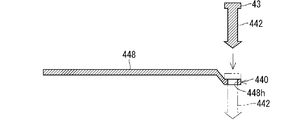
- the plate-shaped portion 448 corresponding to the plate-shaped portion 48 and the fixing portion 442 corresponding to the fixing portion 42 may be separated.
- the plate-shaped portion 448 has a hole 448h formed at the base end portion of the portion corresponding to the plate-shaped portion 48.
- the fixing portion 442 is inserted into the mounting hole 10h of the mounting target member 10 and fixed in a state of penetrating the hole 448h.
- the base end portion of the plate-shaped portion 448 can extend from the fixed portion 442 to the flat harness 30 side in a state of being sandwiched between the mounting target member 10 and the head portion 43.
- the cross-sectional shape of the fixing portion 442 is formed into a non-circular shape (for example, an ellipse, a quadrangle, etc.), and the mounting hole 10h has a non-circular shape corresponding to the cross-sectional shape. It is preferably formed in. Further, in order to restrict the rotation of the plate-shaped portion 448 with respect to the fixed portion 442, the cross-sectional shape of the fixed portion 442 is formed in a non-circular shape, and the hole 448h is formed in a non-circular shape corresponding to the cross-sectional shape. preferable.
- a plurality of plate-shaped portions 448 may be prepared according to the width of the flat harness 30.
- a long plate-shaped portion manufactured assuming the maximum width of the flat harness 30 to be pressed is appropriately removed according to the width of the flat harness 30 to be pressed to form a plate-shaped portion 448. May be good.
- a plurality of holes may be formed at the end of the plate-shaped portion 448, and the fixing portion 442 may penetrate through each of the plurality of holes.
- one end of the plate-shaped portion 448 is fixed at a plurality of locations, and the rotation of the plate-shaped portion 448 is restricted.
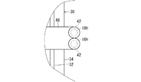
- the fixing portion 42 of the flat harness mounting component 40 may penetrate the side portion on either one side of the flat harness 30.
- the fixing portion 42 penetrates the seat 34 of the flat harness 30.
- the fixing portion 42 is inserted into the mounting hole 10h of the mounting target member 10 in a state of penetrating the flat harness 30, and is fixed to the mounting target member 10.
- the fixing portion 42 itself can press the side portion of the flat harness 30. Therefore, the flat harness 30 is more firmly attached to the attachment target member 10.
- a state in which the fixing portion 42 is penetrated through the side portion of the flat harness 30 may be grasped as a flat harness 500 with mounting parts.
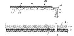
- the flat harness 30 may be attached with a fixed portion 442 and a plate-shaped portion 448 separated from each other (see FIG. 7).
- the fixing portion 442 may be in a state of penetrating the flat harness 30 through the hole 448h of the plate-shaped portion 448.
- the flat harness 500 with mounting parts is provided in a form in which the flat harness mounting parts 40 are integrated with the flat harness 30, and the mounting work of the flat harness 30 is performed in the integrated form. Therefore, the mounting work of the flat harness 30 using the flat harness mounting component 40 can be easily performed.
- the configurations described in the above-described embodiment and each modification can be appropriately combined as long as they do not conflict with each other.
- some of the flat harness mounting parts 40, 40A, 40B, 40C, 40D, and 40E may be integrated parts, and the rest may be divided components. Further, even if a part of the flat harness mounting parts 40, 40A, 40B, 40C, 40D, and 40E is penetrated through the side portion of the flat harness 30, and the rest is fixed to the mounting target member 10 without being penetrated by the flat harness 30. Good.
Abstract
The purpose of the present invention is to enable a flat harness having various widths to be attached to an attachment target part. This flat harness attachment structure for an attachment target member having an attachment surface is provided with: a flat harness arranged on the attachment surface; a fixed part which is fixed to the attachment target member at any one lateral side of the flat harness; and a pressing part extending from the fixed part onto the flat harness so that the flat harness is pressed against the attachment surface.
Description
本開示は、フラットハーネス取付構造、フラットハーネス取付部品及び取付部品付フラットハーネスに関する。
This disclosure relates to a flat harness mounting structure, a flat harness mounting component, and a flat harness with mounting components.
特許文献1は、パネルの裏面にフラット配線材を配索する構造を開示している。パネルには、配索溝が形成されている。フラット配線材は配策溝内に配策される。クリップは、一対の固定爪を有しており、パネルには一対の固定爪が挿入される孔が形成されている。クリップが配線フラット配線材をその幅方向に跨った状態で、一対の固定爪が一対の孔に挿入される。これにより、フラット配線材がパネルに固定される。
Patent Document 1 discloses a structure in which a flat wiring material is arranged on the back surface of a panel. A wiring groove is formed in the panel. The flat wiring material is arranged in the arrangement groove. The clip has a pair of fixing claws, and the panel is formed with a hole into which the pair of fixing claws are inserted. A pair of fixing claws are inserted into the pair of holes with the clip straddling the wiring flat wiring material in the width direction. As a result, the flat wiring material is fixed to the panel.
ここで、様々な幅のフラットハーネスを、取付対象部分に対して取付できるようにすることが望まれている。
Here, it is desired that flat harnesses of various widths can be attached to the attachment target portion.
そこで、本開示は、様々な幅のフラットハーネスを、取付対象部分に対して取付できるようにすることを目的とする。
Therefore, the purpose of this disclosure is to enable flat harnesses of various widths to be attached to the attachment target portion.
本開示のフラットハーネス取付構造は、取付対象面を有する取付対象部材に対するフラットハーネス取付構造であって、前記取付対象面上に配設されるフラットハーネスと、前記フラットハーネスのいずれか一方の側部側で前記取付対象部材に固定される固定部と、前記フラットハーネスを前記取付対象面に押付けるように、前記固定部から前記フラットハーネス上に延在する押付部と、を備えるフラットハーネス取付構造である。
The flat harness mounting structure of the present disclosure is a flat harness mounting structure for a mounting target member having a mounting target surface, and is a side portion of either a flat harness arranged on the mounting target surface or the flat harness. A flat harness mounting structure including a fixing portion fixed to the mounting target member on the side and a pressing portion extending from the fixing portion onto the flat harness so as to press the flat harness against the mounting target surface. Is.
本開示のフラットハーネス取付部品は、取付対象部材に固定される固定部と、基端部が前記固定部に繋がった状態で前記固定部から延出する押付部と、を備え、前記押付部が、前記取付対象部材から離れる方向に向う隙間形成部と、前記取付対象部材の取付対象面に沿って延在する本体部とを含む、フラットハーネス取付部品である。
The flat harness mounting component of the present disclosure includes a fixing portion fixed to a member to be mounted and a pressing portion extending from the fixing portion with a base end portion connected to the fixing portion, and the pressing portion includes the pressing portion. , A flat harness mounting component including a gap forming portion that faces away from the mounting target member and a main body portion that extends along the mounting target surface of the mounting target member.
本開示の取付部品付フラットハーネスは、フラットハーネスと、固定部と押付部とを含む取付部品と、を含み、前記固定部は、取付対象部材に固定可能な部分であり、前記固定部は、前記フラットハーネスのいずれか一方側の側部に貫通しており、前記押付部は前記固定部から前記フラットハーネス側に延出している、取付部品付フラットハーネスである。
The flat harness with mounting components of the present disclosure includes a flat harness and mounting components including a fixing portion and a pressing portion, the fixing portion is a portion that can be fixed to a member to be mounted, and the fixing portion is A flat harness with mounting parts that penetrates one side of the flat harness and extends from the fixed portion to the flat harness side.
本開示によれば、様々な幅のフラットハーネスが取付対象部分に対して取付けされる。
According to the present disclosure, flat harnesses of various widths are attached to the attachment target portion.
[本開示の実施形態の説明]
最初に本開示の実施態様を列記して説明する。 [Explanation of Embodiments of the present disclosure]
First, embodiments of the present disclosure will be listed and described.
最初に本開示の実施態様を列記して説明する。 [Explanation of Embodiments of the present disclosure]
First, embodiments of the present disclosure will be listed and described.
本開示のフラットハーネス取付構造は、次の通りである。
The flat harness mounting structure of the present disclosure is as follows.
(1)取付対象面を有する取付対象部材に対するフラットハーネス取付構造であって、前記取付対象面上に配設されるフラットハーネスと、前記フラットハーネスのいずれか一方の側部側で前記取付対象部材に固定される固定部と、前記フラットハーネスを前記取付対象面に押付けるように、前記固定部から前記フラットハーネス上に延在する押付部と、を備えるフラットハーネス取付構造である。フラットハーネスのいずれか一方側の側部側で固定部が取付対象部材に固定される。固定部からフラットハーネス上に延在する板状部がフラットハーネスを取付対象面に押付ける。このため、フラットハーネスの幅に拘らず、板状部はフラットハーネスを取付対象面に押付ける。これにより、様々な幅のフラットハーネスが、取付対象部材に対して取付けられる。
(1) A flat harness mounting structure for a mounting target member having a mounting target surface, wherein the mounting target member is on one side of the flat harness arranged on the mounting target surface and the flat harness. It is a flat harness mounting structure including a fixed portion fixed to the flat harness and a pressing portion extending from the fixed portion onto the flat harness so as to press the flat harness against the mounting target surface. The fixing portion is fixed to the mounting target member on the side portion side of either one side of the flat harness. A plate-shaped portion extending from the fixed portion onto the flat harness presses the flat harness against the mounting surface. Therefore, regardless of the width of the flat harness, the plate-shaped portion presses the flat harness against the mounting target surface. As a result, flat harnesses of various widths are attached to the members to be attached.
(2)前記押付部は平板状に形成された板状部であってもよい。板状部によって安定してフラットハーネスを押付けることができる。
(2) The pressing portion may be a plate-shaped portion formed in a flat plate shape. The flat harness can be pressed stably by the plate-shaped portion.
(3)前記押付部は、前記固定部に一体形成されていてもよい。
(3) The pressing portion may be integrally formed with the fixing portion.
(4)前記押付部に、前記固定部が貫通する孔が形成され、前記固定部が前記孔に貫通した状態で、前記固定部が前記取付対象部材に固定されていてもよい。固定部が孔に貫通されつつ、取付対象部材に固定される。このため、板状部と固定部との組合作業及び固定部を取付対象部材に固定する作業とが容易に行われる。
(4) A hole through which the fixing portion penetrates is formed in the pressing portion, and the fixing portion may be fixed to the mounting target member in a state where the fixing portion penetrates the hole. The fixing portion is fixed to the member to be attached while being penetrated through the hole. Therefore, the union work of the plate-shaped portion and the fixing portion and the work of fixing the fixing portion to the attachment target member can be easily performed.
(5)前記押付部は、前記フラットハーネスに対していずれか一方の側部側から他方の側部に至る長さに設定されていてもよい。フラットハーネスが、幅方向全体的に押付けられる。
(5) The pressing portion may be set to a length extending from one side portion side to the other side portion with respect to the flat harness. The flat harness is pressed over the entire width direction.
(6)フラットハーネス取付構造は、前記固定部と前記押付部とを複数組備えていてもよい。フラットハーネスを複数箇所で取付対象部材に対して取付けることができる。
(6) The flat harness mounting structure may include a plurality of sets of the fixing portion and the pressing portion. The flat harness can be attached to the member to be attached at a plurality of places.
(7)前記複数組の前記固定部と前記押付部は、前記フラットハーネスに対して異なる側部側で前記取付対象部材に固定されたものを含んでもよい。フラットハーネスの延在方向に沿って異なる側からフラットハーネスが押付けられる。
(7) The plurality of sets of the fixing portion and the pressing portion may include those fixed to the attachment target member on different side portions with respect to the flat harness. The flat harness is pressed from different sides along the extending direction of the flat harness.
(8)1つの前記固定部から前記押付部が複数延在していてもよい。1つの固定部から延出する複数の押付部によってフラットハーネスを押付けることができる。複数の押付部は、フラットハーネスの曲った部分、分岐部分等を押付けることができる。
(8) A plurality of the pressing portions may extend from one fixing portion. The flat harness can be pressed by a plurality of pressing portions extending from one fixed portion. The plurality of pressing portions can press the bent portion, the branch portion, and the like of the flat harness.
本開示のフラットハーネス取付部品は、次の通りである。
The flat harness mounting parts disclosed in this disclosure are as follows.
(9)取付対象部材に固定される固定部と、基端部が前記固定部に繋がった状態で前記固定部から延出する押付部と、を備え、前記押付部が、前記取付対象部材から離れる方向に向う隙間形成部と、前記取付対象部材の取付対象面に沿って延在する本体部とを含む、フラットハーネス取付部品である。押付部は、隙間形成部と本体部とを含む。隙間形成部は、前記取付対象部材から離れる方向に向う。このため、本体部と取付対象面との間にフラットハーネスが配置されるのに適した隙間が形成される。このフラットハーネス固定部品によると、本体部によってフラットハーネスを取付対象面に対して適切に押付けることができる。
(9) A fixing portion fixed to the attachment target member and a pressing portion extending from the fixing portion with the base end portion connected to the fixing portion are provided, and the pressing portion is provided from the attachment target member. It is a flat harness mounting component including a gap forming portion facing away from each other and a main body portion extending along a mounting target surface of the mounting target member. The pressing portion includes a gap forming portion and a main body portion. The gap forming portion faces in a direction away from the mounting target member. Therefore, a gap suitable for arranging the flat harness is formed between the main body and the mounting surface. According to this flat harness fixing component, the flat harness can be appropriately pressed against the mounting target surface by the main body portion.
本開示の取付部品付フラットハーネスは、次の通りである。
The flat harness with mounting parts disclosed in this disclosure is as follows.
(10)フラットハーネスと、固定部と押付部とを含む取付部品と、を含み、前記固定部は、取付対象部材に固定可能な部分であり、前記固定部は、前記フラットハーネスのいずれか一方側の側部に貫通しており、前記押付部は前記固定部から前記フラットハーネス側に延出している、取付部品付フラットハーネスである。フラットハーネスと取付部品とが一体的に取扱われ得る。このため、フラットハーネスを取付対象部材に配設する際に、取付部品を取付対象部材に容易に固定でき、フラットハーネスの取付が容易である。
(10) A flat harness and a mounting component including a fixing portion and a pressing portion are included, the fixing portion is a portion that can be fixed to a member to be mounted, and the fixing portion is one of the flat harnesses. The pressing portion is a flat harness with mounting parts that penetrates the side portion on the side and extends from the fixing portion to the flat harness side. The flat harness and mounting parts can be handled integrally. Therefore, when the flat harness is arranged on the member to be mounted, the mounting component can be easily fixed to the member to be mounted, and the flat harness can be easily mounted.
[本開示の実施形態の詳細]
本開示のフラットハーネス取付構造、フラットハーネス取付部品及び取付部品付フラットハーネスの具体例が、以下に図面を参照しつつ説明される。なお、本開示はこれらの例示に限定されるものではなく、請求の範囲によって示され、請求の範囲と均等の意味および範囲内でのすべての変更が含まれることが意図される。 [Details of Embodiments of the present disclosure]
Specific examples of the flat harness mounting structure, the flat harness mounting component, and the flat harness with mounting component of the present disclosure will be described below with reference to the drawings. It should be noted that the present disclosure is not limited to these examples, but is indicated by the scope of claims and is intended to include all modifications within the meaning and scope equivalent to the scope of claims.
[実施形態]
以下、実施形態に係るフラットハーネス取付構造、フラットハーネス取付部品及び取付部品付フラットハーネスについて説明する。図1はフラットハーネス取付構造20を示す平面図である。図2は図1のII-II線断面図である。 [Embodiment]
Hereinafter, the flat harness mounting structure, the flat harness mounting parts, and the flat harness with mounting parts according to the embodiment will be described. FIG. 1 is a plan view showing a flatharness mounting structure 20. FIG. 2 is a sectional view taken along line II-II of FIG.
以下、実施形態に係るフラットハーネス取付構造、フラットハーネス取付部品及び取付部品付フラットハーネスについて説明する。図1はフラットハーネス取付構造20を示す平面図である。図2は図1のII-II線断面図である。 [Embodiment]
Hereinafter, the flat harness mounting structure, the flat harness mounting parts, and the flat harness with mounting parts according to the embodiment will be described. FIG. 1 is a plan view showing a flat
フラットハーネス取付構造20は、取付対象面11を有する取付対象部材10に、フラットハーネス30を取付けるための構造である。
The flat harness mounting structure 20 is a structure for mounting the flat harness 30 to the mounting target member 10 having the mounting target surface 11.
取付対象部材10としては、例えば、車両における板状部分であることが想定される。取付対象部材10は、平たい板状部分であってもよいし、曲る板状部分であってもよい。ここでは、取付対象部材10は、板状本体部12と、弾性部14とを備える。板状本体部12は、車両における金属ボディ等である。弾性部14は、弾性を有する板状部分である。弾性部14は、例えば、発泡樹脂、不織材等であり、緩衝材或はサイレンサ等の役割を果す部材であることが考えられる。弾性部14は、板状本体部12の一方主面に重ね合されている。つまり、本実施形態において、取付対象部材10は、板状本体部12に弾性部14が積層された積層体である。フラットハーネス30は、取付対象部材10のうち弾性部14側の外向き面に配設される。このため、取付対象部材10のうち弾性部14側の外向き面が取付対象面11である。取付対象部材10には、取付孔10hが形成されているとよい。板状本体部12及び弾性部14の一方が省略されてもよい。
It is assumed that the mounting target member 10 is, for example, a plate-shaped portion in a vehicle. The member 10 to be attached may be a flat plate-shaped portion or a bent plate-shaped portion. Here, the mounting target member 10 includes a plate-shaped main body portion 12 and an elastic portion 14. The plate-shaped main body 12 is a metal body or the like in a vehicle. The elastic portion 14 is a plate-shaped portion having elasticity. The elastic portion 14 is, for example, a foamed resin, a non-woven material, or the like, and is considered to be a member that plays a role of a cushioning material, a silencer, or the like. The elastic portion 14 is superposed on one main surface of the plate-shaped main body portion 12. That is, in the present embodiment, the attachment target member 10 is a laminated body in which the elastic portion 14 is laminated on the plate-shaped main body portion 12. The flat harness 30 is arranged on the outward surface of the member 10 to be mounted on the elastic portion 14 side. Therefore, the outward surface on the elastic portion 14 side of the mounting target member 10 is the mounting target surface 11. It is preferable that the mounting target member 10 is formed with a mounting hole 10h. One of the plate-shaped main body portion 12 and the elastic portion 14 may be omitted.
フラットハーネス取付構造20は、フラットハーネス30と、固定部42と、押付部としての板状部48とを備える。
The flat harness mounting structure 20 includes a flat harness 30, a fixing portion 42, and a plate-shaped portion 48 as a pressing portion.
フラットハーネス30は、複数の線状配線部材を含み、全体的に偏平な形態に形成されたものである。ここでは、フラットハーネス30は、複数の電線32と、シート34とを備える。
The flat harness 30 includes a plurality of linear wiring members and is formed in a flat shape as a whole. Here, the flat harness 30 includes a plurality of electric wires 32 and a seat 34.
電線32は、線状配線部材の一例である。電線32は、芯線と、被覆とを含む。芯線は、金属等の導電部材によって形成された線状導体である。被覆は、芯線の周囲を覆う絶縁部分である。線状配線部材は、電気又は光等を伝送する線状の部材であればよい。例えば、線状配線部材は、電線の他、裸導線、シールド線、ツイスト線、エナメル線、ニクロム線、光ファイバ等であってもよい。
The electric wire 32 is an example of a linear wiring member. The electric wire 32 includes a core wire and a coating. The core wire is a linear conductor formed of a conductive member such as metal. The coating is an insulating portion that surrounds the core wire. The linear wiring member may be any linear member that transmits electricity, light, or the like. For example, the linear wiring member may be a bare wire, a shielded wire, a twisted wire, an enamel wire, a nichrome wire, an optical fiber, or the like, in addition to an electric wire.
シート34は、複数の電線32を偏平な形態に保つシート状の部材である。シート34は、樹脂等によって形成される。シート34は、金属を含んでいてもよい。シート34は、不織シートを含んでもよい。シート34の一方主面に複数の電線32が並列状態で固定される。シート34に対する電線32の固定は、溶着、接着、粘着等によってなされる。溶着は、超音波溶着であってもよいし、加熱溶着であってもよい。複数の電線32がシート34の一方主面に固定されることによって、複数の電線32が平たい状態に保たれる。
The sheet 34 is a sheet-like member that keeps a plurality of electric wires 32 in a flat shape. The sheet 34 is made of resin or the like. The sheet 34 may contain metal. The sheet 34 may include a non-woven sheet. A plurality of electric wires 32 are fixed in parallel on one main surface of the sheet 34. The electric wire 32 is fixed to the sheet 34 by welding, adhesion, adhesion, or the like. The welding may be ultrasonic welding or heat welding. By fixing the plurality of electric wires 32 to one main surface of the sheet 34, the plurality of electric wires 32 are kept in a flat state.
フラットハーネス30は、接続先となる各電気部品の位置に応じて分岐していてもよい。図1においては、複数の電線32のうちの一部の電線32aが外側方に分岐している例が示されている。この場合、シート34は、電線32の経路に沿って分岐するように形成されていてもよい。フラットハーネス30のうち最も多くの電線32が設けられた部分が幹線部30aとして後の説明で参照される場合がある。また、上記電線32aが分岐した部分が枝線部30bとして後の説明で参照される場合がある。各電線32の端部は、コネクタ等を介して電気部品等に接続される。シート34上において複数の電線32が複数層積層されていてもよい。
The flat harness 30 may be branched according to the position of each electrical component to be connected. FIG. 1 shows an example in which some electric wires 32a of the plurality of electric wires 32 are branched outward. In this case, the sheet 34 may be formed so as to branch along the path of the electric wire 32. The portion of the flat harness 30 provided with the largest number of electric wires 32 may be referred to as a trunk line portion 30a in a later description. Further, the portion where the electric wire 32a is branched may be referred to later as a branch line portion 30b. The end of each electric wire 32 is connected to an electric component or the like via a connector or the like. A plurality of electric wires 32 may be laminated in a plurality of layers on the sheet 34.
フラットハーネス30は、上記例に限られない。複数の電線は、平たい枠部材等によって偏平状態に保たれていてもよい。複数の電線が偏平な形態となるように並列された形態で直接接合されていてもよい。また、フラットハーネス30は、FPC(Flexible printed circuits)等のように、複数の線状導体が絶縁部材によって相互に絶縁された状態で偏平状態に保たれたものであってもよい。すなわち、フラットハーネスは、複数の線状導体が、相互に絶縁された状態で偏平な形態に保持され、全体として幅よりも厚みが小さく形成された配線部材であればよい。
The flat harness 30 is not limited to the above example. The plurality of electric wires may be kept flat by a flat frame member or the like. A plurality of electric wires may be directly joined in a parallel form so as to have a flat form. Further, the flat harness 30 may be maintained in a flat state in a state where a plurality of linear conductors are mutually insulated by an insulating member, such as FPC (Flexible printed circuits). That is, the flat harness may be a wiring member in which a plurality of linear conductors are held in a flat form in a state of being insulated from each other and formed to have a thickness smaller than a width as a whole.
かかるフラットハーネス30は、取付対象面11上に当該取付対象面11に平行な姿勢で配設される。ここでは、電線32は、シート34に対して取付対象面11とは反対側に位置している。電線32は、シート34に対して取付対象面11側に位置していてもよい。
The flat harness 30 is arranged on the mounting target surface 11 in a posture parallel to the mounting target surface 11. Here, the electric wire 32 is located on the side opposite to the mounting target surface 11 with respect to the seat 34. The electric wire 32 may be located on the mounting target surface 11 side with respect to the seat 34.
固定部42は、フラットハーネス30のいずれか一方の側部側で取付対象部材10に固定される部分である。板状部48は、フラットハーネス30を取付対象面11に押付けるように、固定部42からフラットハーネス30上に延在する部分である。本実施形態では、板状部48は、固定部42に一体形成されている。より具体的には、板状部48と固定部42とは、溶融樹脂が金型内に注入されることによって金型一体形成されている。このため、板状部48と固定部42とは、境界面無く一体的に繋がっている。固定部42と板状部48とが一体形成されたものは、フラットハーネス取付部品40と称されてもよい。ここでは、押付部は、帯状に延在する板状部である例が説明される。押付部は、丸棒状、四角棒状、三角棒状等であってもよい。
The fixing portion 42 is a portion fixed to the mounting target member 10 on either side of the flat harness 30. The plate-shaped portion 48 is a portion extending from the fixing portion 42 onto the flat harness 30 so as to press the flat harness 30 against the mounting target surface 11. In the present embodiment, the plate-shaped portion 48 is integrally formed with the fixing portion 42. More specifically, the plate-shaped portion 48 and the fixing portion 42 are integrally formed with the mold by injecting the molten resin into the mold. Therefore, the plate-shaped portion 48 and the fixed portion 42 are integrally connected without a boundary surface. The one in which the fixing portion 42 and the plate-shaped portion 48 are integrally formed may be referred to as a flat harness mounting component 40. Here, an example will be described in which the pressing portion is a plate-shaped portion extending in a strip shape. The pressing portion may have a round bar shape, a square bar shape, a triangular bar shape, or the like.
より具体的には、固定部42は、取付対象部材10に形成された取付孔10hに抜け止状態に嵌込可能に構成されている。かかる固定部42は、例えば、長尺本体部42aと、引っ掛かり部42bとを含む。長尺本体部42aは、取付孔10hに挿入されて取付対象部材10の裏面側に達することが可能な長さ寸法に形成される。引っ掛かり部42bは、長尺本体部42aの先端部から外方に突出するように形成されて、取付孔10hの周縁部に取付対象部材10の裏面側から引っ掛かり可能に構成される。引っ掛かり部42bは、例えば、板ばね形状等を利用した弾性変形構造によって、取付孔10hの周縁部に引っ掛かり可能な突出状態から取付孔10hを通過可能な退避状態に弾性変形することができる。かかる固定部42の構成としては、ハーネス用クリップ、ハーネス用クランプ、プッシュリベット(push rivet)等として周知の構成のものが採用されてもよい。
More specifically, the fixing portion 42 is configured to be able to be fitted into the mounting hole 10h formed in the mounting target member 10 in a retaining state. The fixing portion 42 includes, for example, a long main body portion 42a and a hooking portion 42b. The long main body portion 42a is formed to have a length dimension that allows it to be inserted into the mounting hole 10h and reach the back surface side of the mounting target member 10. The hooking portion 42b is formed so as to project outward from the tip end portion of the long main body portion 42a, and is configured to be hookable from the back surface side of the mounting target member 10 to the peripheral edge portion of the mounting hole 10h. The hooking portion 42b can be elastically deformed from a protruding state in which it can be hooked on the peripheral edge of the mounting hole 10h to a retracted state in which it can pass through the mounting hole 10h, for example, by an elastic deformation structure utilizing a leaf spring shape or the like. As the configuration of the fixing portion 42, well-known configurations such as a harness clip, a harness clamp, a push rivet, and the like may be adopted.
固定部42の基端部には、外側に張出す頭部43が形成されている。ここでは、頭部43は、固定部42の基端部の周方向全体に張出す円板状に形成されている。固定部42が取付孔10hに挿入された状態では、頭部43が取付孔10hの一方側(取付対象面11側)開口周縁部に引っ掛かり、引っ掛かり部42bが取付孔10hの他方側開口周縁部に引っ掛かる。この状態で、弾性部14が圧縮した状態となっていてもよい。この場合、弾性部14の弾性復元力によって頭部43が板状本体部12から遠ざかる方向に継続的に押されることになる。このため、固定部42が傾き難くなり、フラットハーネス取付部品40の姿勢が安定する。
A head 43 extending outward is formed at the base end of the fixing portion 42. Here, the head 43 is formed in a disk shape overhanging the entire circumferential direction of the base end portion of the fixing portion 42. In the state where the fixing portion 42 is inserted into the mounting hole 10h, the head 43 is caught on one side (mounting target surface 11 side) opening peripheral edge portion of the mounting hole 10h, and the hooked portion 42b is caught on the other side opening peripheral edge portion of the mounting hole 10h. Get caught in. In this state, the elastic portion 14 may be in a compressed state. In this case, the elastic restoring force of the elastic portion 14 causes the head 43 to be continuously pushed in the direction away from the plate-shaped main body portion 12. Therefore, the fixing portion 42 is less likely to be tilted, and the posture of the flat harness mounting component 40 is stabilized.
板状部48は、固定部42の基端部から当該固定部42の軸方向から遠ざかる外方に延出する。ここでは、板状部48の基端部が固定部42の基端部に繋がっている。板状部48は、隙間形成部48aと、本体部48bとを備える。隙間形成部48aは、固定部42の基端部に繋がった部分から取付対象部材10から離れる方向に向うように形成されている。ここでは、隙間形成部48aは、頭部43の周囲の一部から外方向に向うのに従って固定部42の先端部とは逆方向に向うように傾斜している。本体部48bは、隙間形成部48aの先端部から取付対象面11に沿って延在している。ここでは、本体部48bは、細長い板状に形成されている。本体部48bは、隙間形成部48aの先端部から固定部42の軸方向に対して直交しつつ当該固定部42から遠ざかる方向に向けて延在している。このため、頭部43の内向き面と本体部48bの内向き面との間には、固定部42の軸方向に沿った方向において、隙間形成部48aの傾き分の位置の違いが生じ得る。固定部42が取付対象部材10に固定された状態で、頭部43の内向き面は、取付対象面11に接した状態となる。この状態で、本体部48bと取付対象面11との間には、隙間形成部48a傾きに応じた隙間が形成される。この隙間に、フラットハーネス30が配設される。上記隙間は、フラットハーネス30の厚み寸法(シート34の厚みに電線32の直径が付加された寸法)よりも小さいことが好ましい。これにより、本体部48bがフラットハーネス30をより確実に押えることができる。上記隙間形成部48aは、固定部42に対して傾斜している必要は無く、クランク状に形成されていてもよい。
The plate-shaped portion 48 extends outward from the base end portion of the fixing portion 42 away from the axial direction of the fixing portion 42. Here, the base end portion of the plate-shaped portion 48 is connected to the base end portion of the fixing portion 42. The plate-shaped portion 48 includes a gap forming portion 48a and a main body portion 48b. The gap forming portion 48a is formed so as to face in a direction away from the attachment target member 10 from the portion connected to the base end portion of the fixing portion 42. Here, the gap forming portion 48a is inclined so as to face outward from a part of the periphery of the head 43 and to face the opposite direction to the tip end portion of the fixing portion 42. The main body portion 48b extends from the tip end portion of the gap forming portion 48a along the mounting target surface 11. Here, the main body portion 48b is formed in an elongated plate shape. The main body portion 48b extends from the tip end portion of the gap forming portion 48a in a direction away from the fixing portion 42 while being orthogonal to the axial direction of the fixing portion 42. Therefore, there may be a difference in the position of the inclination of the gap forming portion 48a between the inward surface of the head 43 and the inward surface of the main body 48b in the direction along the axial direction of the fixed portion 42. .. With the fixing portion 42 fixed to the mounting target member 10, the inward facing surface of the head 43 is in contact with the mounting target surface 11. In this state, a gap is formed between the main body portion 48b and the mounting target surface 11 according to the inclination of the gap forming portion 48a. The flat harness 30 is arranged in this gap. The gap is preferably smaller than the thickness dimension of the flat harness 30 (the thickness of the sheet 34 plus the diameter of the electric wire 32). As a result, the main body 48b can more reliably press the flat harness 30. The gap forming portion 48a does not have to be inclined with respect to the fixing portion 42, and may be formed in a crank shape.
ここで、取付対象となるフラットハーネス30の厚みは、電線32の径、シート34の厚み等によって変更され得る。上記隙間形成部48aは、取付対象となるフラットハーネス30の厚みに応じた構成とされてもよい。例えば、図3に示すように、フラットハーネス30Aの厚みが比較的小さい場合、隙間形成部48a1の傾斜が小さく設定されてもよい。これにより、固定部42の軸方向に沿った方向において、頭部43の内向き面と本体部48bの内向き面との差が小さくなり、比較的厚みの小さいフラットハーネス30Aを押付けるのに適した構成が得られる。また、例えば、図4に示すように、フラットハーネス30Bの厚みが比較的大きい場合、隙間形成部48a2の傾斜が大きく設定されてもよい。これにより、固定部42の軸方向に沿った方向において、頭部43の内向き面と本体部48bの内向き面との差を大きくすることができ、比較的厚みの大きいフラットハーネス30Bを押付けるのに適した構成とすることができる。
Here, the thickness of the flat harness 30 to be attached can be changed depending on the diameter of the electric wire 32, the thickness of the sheet 34, and the like. The gap forming portion 48a may be configured according to the thickness of the flat harness 30 to be attached. For example, as shown in FIG. 3, when the thickness of the flat harness 30A is relatively small, the inclination of the gap forming portion 48a1 may be set to be small. As a result, the difference between the inward surface of the head 43 and the inward surface of the main body 48b becomes small in the direction along the axial direction of the fixed portion 42, and the flat harness 30A having a relatively small thickness can be pressed. A suitable configuration can be obtained. Further, for example, as shown in FIG. 4, when the thickness of the flat harness 30B is relatively large, the inclination of the gap forming portion 48a2 may be set to be large. As a result, the difference between the inward surface of the head 43 and the inward surface of the main body 48b can be increased in the direction along the axial direction of the fixed portion 42, and the flat harness 30B having a relatively large thickness is pushed. It can be configured to be suitable for attachment.
板状部48の長さ寸法は、フラットハーネス30の一方の側部から他方の側部に至る長さに設定されていることが好ましい。本実施形態においては、固定部42は、フラットハーネス30の一方の側部から外方の位置で、取付対象部材10に固定される。このため、板状部48の長さ寸法は、フラットハーネス30の幅寸法以上であることが好ましい。後に説明するように、固定部42がフラットハーネス30の一方の側部の縁よりも内側で当該側部を貫通している場合がある。この場合、板状部48の長さ寸法が、フラットハーネス30の幅寸法未満であっても、板状部48の長さ寸法は、フラットハーネス30の一方の側部から他方の側部に至る長さに設定され得る。なお、板状部48の長さ寸法は、フラットハーネス30の一方の側部から他方の側部に至る手前の長さに設定されていてもよい。ここでは、板状部48がフラットハーネス30の幅方向に沿う姿勢である例が説明された。しかしながら、板状部48は、フラットハーネス30の幅方向に対して斜め姿勢であってもよい。
The length dimension of the plate-shaped portion 48 is preferably set to the length from one side portion of the flat harness 30 to the other side portion. In the present embodiment, the fixing portion 42 is fixed to the attachment target member 10 at a position outward from one side portion of the flat harness 30. Therefore, the length dimension of the plate-shaped portion 48 is preferably equal to or larger than the width dimension of the flat harness 30. As will be described later, the fixing portion 42 may penetrate the side portion inside the edge of one side portion of the flat harness 30. In this case, even if the length dimension of the plate-shaped portion 48 is less than the width dimension of the flat harness 30, the length dimension of the plate-shaped portion 48 extends from one side portion of the flat harness 30 to the other side portion. Can be set to length. The length dimension of the plate-shaped portion 48 may be set to the length before reaching from one side portion of the flat harness 30 to the other side portion. Here, an example in which the plate-shaped portion 48 is in a posture along the width direction of the flat harness 30 has been described. However, the plate-shaped portion 48 may be in an oblique posture with respect to the width direction of the flat harness 30.
固定部と板状部とを含む組は、複数設けられていてもよい。図1において、上記固定部42と板状部48とを含むフラットハーネス取付部品40の他に、フラットハーネス取付部品40A、40B、40C、40D、40Eが図示されている。
A plurality of sets including the fixed portion and the plate-shaped portion may be provided. In FIG. 1, in addition to the flat harness mounting component 40 including the fixing portion 42 and the plate-shaped portion 48, the flat harness mounting parts 40A, 40B, 40C, 40D, and 40E are shown.
フラットハーネス取付部品40Aは、フラットハーネス取付部品40と同様の固定部42と板状部48とを備える部品である。フラットハーネス取付部品40、40Aに着目すると、フラットハーネス取付部品40と、フラットハーネス取付部品40Aとは、フラットハーネス30に対して異なる側部側で取付対象部材10に固定されている。また、フラットハーネス取付部品40、40Aとは、フラットハーネス30の延在方向において異なる位置に設けられている。
The flat harness mounting component 40A is a component including a fixing portion 42 and a plate-shaped portion 48 similar to the flat harness mounting component 40. Focusing on the flat harness mounting parts 40 and 40A, the flat harness mounting part 40 and the flat harness mounting part 40A are fixed to the mounting target member 10 on different sides of the flat harness 30. Further, the flat harness mounting parts 40 and 40A are provided at different positions in the extending direction of the flat harness 30.
より具体的には、フラットハーネス取付部品40については、固定部42がフラットハーネス30の一方の側部側(ここでは、当該側部の外側)で取付対象部材10に固定されている。板状部48は、フラットハーネス30の一方の側部から他方の側部に向うように、当該フラットハーネス30を横切っている。
More specifically, with respect to the flat harness mounting component 40, the fixing portion 42 is fixed to the mounting target member 10 on one side side (here, the outside of the side portion) of the flat harness 30. The plate-shaped portion 48 crosses the flat harness 30 so as to face from one side portion of the flat harness 30 to the other side portion.
フラットハーネス取付部品40Aは、フラットハーネス取付部品40に対してフラットハーネス30の延在方向に沿って間隔をあけて隣合う位置に設けられている。フラットハーネス取付部品40Aの姿勢は、上記フラットハーネス取付部品40に対して、フラットハーネス30の幅方向中央ラインに対して対称となっている。つまり、固定部42がフラットハーネス30の他方の側部側(ここでは、当該側部の外側)で取付対象部材10に固定されている。板状部48は、フラットハーネス30の他方の側部から一方の側部に向うように、当該フラットハーネス30を横切っている。
The flat harness mounting component 40A is provided at a position adjacent to the flat harness mounting component 40 at intervals along the extending direction of the flat harness 30. The posture of the flat harness mounting component 40A is symmetrical with respect to the flat harness mounting component 40 with respect to the center line in the width direction of the flat harness 30. That is, the fixing portion 42 is fixed to the mounting target member 10 on the other side portion side (here, the outside of the side portion) of the flat harness 30. The plate-shaped portion 48 crosses the flat harness 30 so as to face one side from the other side of the flat harness 30.
ここでは、フラットハーネス取付部品40、40Aの板状部48が、フラットハーネス30の延在方向に沿って異なる位置で、フラットハーネス30の異なる側部から延在して当該フラットハーネス30を押付ける。フラットハーネス取付部品40、40Aは、固定部42に近い側で、フラットハーネス30を効果的に押付けることができると考えられる。このため、当該フラットハーネス30がある程度の範囲に亘り効果的に取付対象面11に押付けられる。フラットハーネス取付部品40、40Aがより多数設けられている場合には、固定部42は、フラットハーネス30の両側部に対して交互に配置されるようにしてもよい。
Here, the plate-shaped portions 48 of the flat harness mounting parts 40 and 40A extend from different side portions of the flat harness 30 at different positions along the extending direction of the flat harness 30 to press the flat harness 30. .. It is considered that the flat harness mounting parts 40 and 40A can effectively press the flat harness 30 on the side close to the fixing portion 42. Therefore, the flat harness 30 is effectively pressed against the mounting target surface 11 over a certain range. When a larger number of flat harness mounting parts 40 and 40A are provided, the fixing portions 42 may be arranged alternately with respect to both side portions of the flat harness 30.
フラットハーネス取付部品40Bは、固定部42と、板状部48Bとを備える。固定部42は、上記したものと同様構成である。
The flat harness mounting part 40B includes a fixing portion 42 and a plate-shaped portion 48B. The fixing portion 42 has the same configuration as that described above.
板状部48Bは、上記板状部48よりも幅広に形成されている。板状部48Bが幅広に形成されることで、板状部48Bによってフラットハーネス30が保護される。例えば、フラットハーネス30の一部の近くにエッジ状の部分等が存在している場合に、本フラットハーネス取付部品40Bが設けられるとよい。板状部48Bの幅は、保護が望まれる領域に応じて適宜設定され得る。例えば、板状部48Bは、固定部42の幅より幅広に設定されるとよい。固定部42の幅とは、固定部42の軸方向及び板状部48Bの延在方向の両方に対して直交する方向の寸法である。また、例えば、板状部48Bは、フラットハーネス30の幅よりも幅広に設定されてもよい。
The plate-shaped portion 48B is formed wider than the plate-shaped portion 48. By forming the plate-shaped portion 48B wide, the flat harness 30 is protected by the plate-shaped portion 48B. For example, when an edge-shaped portion or the like exists near a part of the flat harness 30, the flat harness mounting component 40B may be provided. The width of the plate-shaped portion 48B can be appropriately set depending on the region where protection is desired. For example, the plate-shaped portion 48B may be set wider than the width of the fixed portion 42. The width of the fixed portion 42 is a dimension in a direction orthogonal to both the axial direction of the fixed portion 42 and the extending direction of the plate-shaped portion 48B. Further, for example, the plate-shaped portion 48B may be set wider than the width of the flat harness 30.
フラットハーネス取付部品40Cは、固定部42と、板状部48Cとを備える。固定部42は、上記したものと同様構成である。板状部48Cは、上記板状部48よりも短い。フラットハーネス取付部品40Dは、固定部42と、板状部48Dとを備える。固定部42は、上記したものと同様構成である。板状部48Dは、上記板状部48よりも短い。
The flat harness mounting component 40C includes a fixing portion 42 and a plate-shaped portion 48C. The fixing portion 42 has the same configuration as that described above. The plate-shaped portion 48C is shorter than the plate-shaped portion 48. The flat harness mounting component 40D includes a fixing portion 42 and a plate-shaped portion 48D. The fixing portion 42 has the same configuration as that described above. The plate-shaped portion 48D is shorter than the plate-shaped portion 48.
フラットハーネス取付部品40C、40Dに着目すると、フラットハーネス取付部品40Cと、フラットハーネス取付部品40Dとは、フラットハーネス30に対して異なる側部側で取付対象部材10に固定されている。また、フラットハーネス取付部品40C、40Dとは、フラットハーネス30の延在方向において同じ位置に設けられている。
Focusing on the flat harness mounting parts 40C and 40D, the flat harness mounting part 40C and the flat harness mounting part 40D are fixed to the mounting target member 10 on different sides of the flat harness 30. Further, the flat harness mounting parts 40C and 40D are provided at the same positions in the extending direction of the flat harness 30.
より具体的には、フラットハーネス取付部品40Cについては、固定部42がフラットハーネス30の一方の側部側(ここでは、当該側部の外側)で取付対象部材10に固定されている。板状部48は、フラットハーネス30の一方の側部から他方の側部の手前に向うように延在している。
More specifically, for the flat harness mounting component 40C, the fixing portion 42 is fixed to the mounting target member 10 on one side side (here, the outside of the side portion) of the flat harness 30. The plate-shaped portion 48 extends from one side portion of the flat harness 30 toward the front of the other side portion.
フラットハーネス取付部品40Dは、フラットハーネス取付部品40Cに対してフラットハーネス30の延在方向に沿って同じ位置に設けられている。フラットハーネス取付部品40Dの姿勢は、上記フラットハーネス取付部品40Cに対して、フラットハーネス30の幅方向中央ラインに対して対称となっている。つまり、固定部42がフラットハーネス30の他方の側部側(ここでは、当該側部の外側)で取付対象部材10に固定されている。板状部48は、フラットハーネス30の他方の側部から一方の側部の手前に向うように延在している。
The flat harness mounting component 40D is provided at the same position with respect to the flat harness mounting component 40C along the extending direction of the flat harness 30. The posture of the flat harness mounting component 40D is symmetrical with respect to the flat harness mounting component 40C with respect to the center line in the width direction of the flat harness 30. That is, the fixing portion 42 is fixed to the mounting target member 10 on the other side portion side (here, the outside of the side portion) of the flat harness 30. The plate-shaped portion 48 extends from the other side portion of the flat harness 30 toward the front of the one side portion.
このため、フラットハーネス取付部品40Cの板状部48Cと、フラットハーネス取付部品40Dの板状部48Dとは、フラットハーネス30を横切る1つの直線上に沿っている。また、板状部48C、48Dは、フラットハーネス30の幅方向中間部で対向している。板状部48C、48Dの長さは同じであってもよいし、異なっていてもよい。
Therefore, the plate-shaped portion 48C of the flat harness mounting component 40C and the plate-shaped portion 48D of the flat harness mounting component 40D are along one straight line that crosses the flat harness 30. Further, the plate-shaped portions 48C and 48D face each other at the intermediate portion in the width direction of the flat harness 30. The lengths of the plate-shaped portions 48C and 48D may be the same or may be different.
ここでは、フラットハーネス取付部品40C、40Dの板状部48C、48Dが、フラットハーネス30の延在方向に沿って同じ位置で、フラットハーネス30の異なる側部から延在して当該フラットハーネス30を押付ける。フラットハーネス取付部品40C、40Dは、固定部42に近い側で、フラットハーネス30を効果的に押付けることができると考えられる。このため、当該フラットハーネス30の一部の両側部が効果的に取付対象面11に押付けられる。
Here, the plate-shaped portions 48C and 48D of the flat harness mounting parts 40C and 40D extend from different side portions of the flat harness 30 at the same position along the extending direction of the flat harness 30 to extend the flat harness 30. Press. It is considered that the flat harness mounting parts 40C and 40D can effectively press the flat harness 30 on the side close to the fixing portion 42. Therefore, both side portions of a part of the flat harness 30 are effectively pressed against the mounting target surface 11.
フラットハーネス取付部品40Eは、固定部42と、板状部48E1と、板状部48E2とを備える。固定部42は、上記固定部42と同様構成である。
The flat harness mounting component 40E includes a fixing portion 42, a plate-shaped portion 48E1, and a plate-shaped portion 48E2. The fixing portion 42 has the same configuration as the fixing portion 42.
板状部48E1と板状部48E2とは、上記板状部48と同様構成である。板状部48E1と板状部48E2との長さ寸法は、押付対象となるフラットハーネス30の幅等に応じて設定される。
The plate-shaped portion 48E1 and the plate-shaped portion 48E2 have the same configuration as the plate-shaped portion 48. The length dimension of the plate-shaped portion 48E1 and the plate-shaped portion 48E2 is set according to the width and the like of the flat harness 30 to be pressed.
1つの固定部42から複数の板状部48E1、板状部48E2が延出している。板状部48E1は、フラットハーネス30のうち幹線部30aを押付ける部分である。この板状部48E1は、当該幹線部30aの幅寸法以上の長さ寸法に設定されている。板状部48E2は、フラットハーネス30のうち枝線部30bを押付ける部分である。この板状部48E2は、当該枝線部30bの幅寸法以上の長さ寸法に設定されている。
A plurality of plate-shaped portions 48E1 and plate-shaped portions 48E2 extend from one fixing portion 42. The plate-shaped portion 48E1 is a portion of the flat harness 30 that presses the trunk line portion 30a. The plate-shaped portion 48E1 is set to a length dimension equal to or larger than the width dimension of the trunk line portion 30a. The plate-shaped portion 48E2 is a portion of the flat harness 30 that presses the branch line portion 30b. The plate-shaped portion 48E2 is set to a length dimension equal to or larger than the width dimension of the branch line portion 30b.
固定部42は、幹線部30aの一側と枝線部30bの一側とが交わる箇所の外側位置で、取付対象部材10に固定されている。幹線部30aに対して枝線部30bは、直交姿勢で延出している。板状部48E1と板状部48E2とは互いに直交姿勢で延在している。このため、板状部48E1は、幹線部30aを横切る姿勢で当該幹線部30aを押付けている。また、板状部48E2は、枝線部30bを横切る姿勢で、当該枝線部30bを押付けている。
The fixing portion 42 is fixed to the attachment target member 10 at a position outside the portion where one side of the trunk line portion 30a and one side of the branch line portion 30b intersect. The branch line portion 30b extends in an orthogonal posture with respect to the trunk line portion 30a. The plate-shaped portion 48E1 and the plate-shaped portion 48E2 extend in an orthogonal posture with each other. Therefore, the plate-shaped portion 48E1 presses the trunk line portion 30a in a posture of crossing the trunk line portion 30a. Further, the plate-shaped portion 48E2 presses the branch line portion 30b in a posture of crossing the branch line portion 30b.
板状部48E1と板状部48E2とがなす角は、幹線部30aと枝線部30bとがなす角等に応じて変更され得る。固定部42から3つ以上の板状部が延出してもよい。板状部48E1と板状部48E2とは、フラットハーネス30が分岐している部分だけでなく、フラットハーネス30が曲っている部分においてもその曲げ部分の前後部分を押付けることができる。
The angle formed by the plate-shaped portion 48E1 and the plate-shaped portion 48E2 can be changed according to the angle formed by the trunk line portion 30a and the branch line portion 30b. Three or more plate-shaped portions may extend from the fixed portion 42. The plate-shaped portion 48E1 and the plate-shaped portion 48E2 can press the front and rear portions of the bent portion not only in the portion where the flat harness 30 is branched but also in the portion where the flat harness 30 is bent.
上記フラットハーネス取付部品40、40A、40B、40C、40D、40Eの板状部48、48B、48C、48D、48E1、48E2の長さ寸法は、フラットハーネス30のうち押付対象となる部分の幅に応じた寸法に設定されるとよい。
The length dimension of the plate-shaped portions 48, 48B, 48C, 48D, 48E1 and 48E2 of the flat harness mounting parts 40, 40A, 40B, 40C, 40D and 40E is the width of the portion of the flat harness 30 to be pressed. It is good to set the dimensions according to it.
この場合、板状部48、48B、48C、48D、48E1、48E2として、フラットハーネス30のうち押付対象となる部分の幅に応じたものが金型成形等によって製造されてもよい。また、例えば、押付対象として想定されるフラットハーネス30の最大幅が想定され、板状部148として想定される最大幅に応じた長さのものが製造されるとよい(図1において2点鎖線で示す板状部148参照)。この場合、フラットハーネス30の幅に応じて、板状部148の先端部が除去されて、所望の長さ寸法の板状部48が形成されるとよい。板状部148の先端部は、刃で切断すること、折ること等によって除去され得る。
In this case, the plate-shaped portions 48, 48B, 48C, 48D, 48E1, and 48E2 may be manufactured by molding or the like according to the width of the portion of the flat harness 30 to be pressed. Further, for example, the maximum width of the flat harness 30 assumed to be pressed is assumed, and the length corresponding to the maximum width assumed as the plate-shaped portion 148 may be manufactured (two-dot chain line in FIG. 1). (See plate-shaped portion 148 indicated by). In this case, it is preferable that the tip portion of the plate-shaped portion 148 is removed according to the width of the flat harness 30 to form the plate-shaped portion 48 having a desired length dimension. The tip of the plate-shaped portion 148 can be removed by cutting with a blade, folding, or the like.
また、例えば、フラットハーネス取付部品240として、板状部248の両端部に固定部42が設けられたものが製造されてもよい(図1において2点鎖線で示すフラットハーネス取付部品240参照)。この場合、板状部248の中間部が分離されることで、所望の長さ寸法の板状部48を有するフラットハーネス取付部品40Aが製造され得る。上記フラットハーネス取付部品240は、そのままの形態で、フラットハーネス30を押付ける部品としても使用され得る。
Further, for example, as the flat harness mounting component 240, a flat harness mounting component 240 having fixing portions 42 provided at both ends of the plate-shaped portion 248 may be manufactured (see the flat harness mounting component 240 shown by the alternate long and short dash line in FIG. 1). In this case, by separating the intermediate portion of the plate-shaped portion 248, the flat harness mounting component 40A having the plate-shaped portion 48 having a desired length dimension can be manufactured. The flat harness mounting component 240 can be used as it is as a component for pressing the flat harness 30.
本実施形態によると、フラットハーネス30のいずれか一方側の端部側で固定部42が取付対象部材10に固定される。固定部42からフラットハーネス30上に延在する板状部48、48B、48C、48D、48E1、48E2がフラットハーネス30を取付対象面11に押付ける。このため、フラットハーネス30の幅に拘らず、板状部48は、フラットハーネス30を取付対象面11に押付ける。これにより、様々な幅のフラットハーネス30が、取付対象部材10に対して取付けられる。
According to the present embodiment, the fixing portion 42 is fixed to the mounting target member 10 on the end side of any one side of the flat harness 30. Plate-shaped portions 48, 48B, 48C, 48D, 48E1 and 48E2 extending from the fixed portion 42 onto the flat harness 30 press the flat harness 30 against the mounting target surface 11. Therefore, regardless of the width of the flat harness 30, the plate-shaped portion 48 presses the flat harness 30 against the mounting target surface 11. As a result, the flat harness 30 having various widths is attached to the attachment target member 10.
また、板状部48、48B、48C、48D、48E1、48E2の一端部側のみに固定部42が設けられ、取付対象部材10には、板状部48、48B、48C、48D、48E1、48E2の一端部側のみに取付孔10hが形成されればよい。このため、取付作業性が向上すると共に、取付対象部材10による遮音性が向上する。
Further, the fixing portion 42 is provided only on one end side of the plate-shaped portions 48, 48B, 48C, 48D, 48E1 and 48E2, and the mounting target member 10 is provided with the plate-shaped portions 48, 48B, 48C, 48D, 48E1 and 48E2. It is sufficient that the mounting hole 10h is formed only on one end side of the above. Therefore, the mounting workability is improved, and the sound insulation of the mounting target member 10 is improved.
また、板状部48、48B、48C、48D、48E1、48E2は、電線32、32aをシート34に対して押付けている。このため、シート34からの電線32、32aの浮きも抑制される。
Further, the plate-shaped portions 48, 48B, 48C, 48D, 48E1 and 48E2 press the electric wires 32 and 32a against the sheet 34. Therefore, the floating of the electric wires 32 and 32a from the sheet 34 is also suppressed.
また、板状部48、48B、48C、48D、48E1、48E2は、固定部42に一体形成されているため、部品点数が少なくなる。また、フラットハーネス30を取付対象部材10に取付ける際に必要な部品数を削減できるため、フラットハーネス30の取付が容易である。
Further, since the plate-shaped portions 48, 48B, 48C, 48D, 48E1 and 48E2 are integrally formed with the fixed portion 42, the number of parts is reduced. Further, since the number of parts required for attaching the flat harness 30 to the attachment target member 10 can be reduced, the flat harness 30 can be easily attached.
また、板状部48、48B、48C、48D、48E1、48E2の一端部のみが固定部42によって固定される。このため、板状部48、48B,48C、48D、48E1、48E2がフラットハーネス30の幅に応じて除去されるか、その端部がフラットハーネス30の幅方向中間部又は外側にはみ出た状態で使用され得る。これにより、フラットハーネス取付部品40、40A、40B、40C、40D、40Eの種類数を削減することが可能となり、部品の製造管理が容易となる。
Further, only one end of the plate-shaped portions 48, 48B, 48C, 48D, 48E1 and 48E2 is fixed by the fixing portion 42. Therefore, the plate-shaped portions 48, 48B, 48C, 48D, 48E1 and 48E2 are removed according to the width of the flat harness 30, or the end portions thereof protrude from the middle portion in the width direction or the outside of the flat harness 30. Can be used. This makes it possible to reduce the number of types of flat harness mounting parts 40, 40A, 40B, 40C, 40D, and 40E, and facilitates manufacturing control of parts.
また、板状部48、48B,48E1、48E2がフラットハーネス30の幅方向全体を押付ける構成であるため、フラットハーネス30が取付対象面11から浮き難い。
Further, since the plate-shaped portions 48, 48B, 48E1 and 48E2 are configured to press the entire width direction of the flat harness 30, the flat harness 30 is difficult to float from the mounting target surface 11.
また、フラットハーネス取付部品40、40A、40B、40C、40D、40Eが複数設けられているため、フラットハーネス30を複数箇所で押付けることができる。
Further, since a plurality of flat harness mounting parts 40, 40A, 40B, 40C, 40D, and 40E are provided, the flat harness 30 can be pressed at a plurality of places.
フラットハーネス取付部品40、40Aがフラットハーネス30に対して異なる側部側で取付対象部材10に固定される。または、フラットハーネス取付部品40、C40Dがフラットハーネス30に対して異なる側部側で取付対象部材10に固定される。フラットハーネス取付部品40、40A、フラットハーネス取付部品40C、40Dは固定部42側でフラットハーネス30をよりしっかりと押付けることができる。その固定箇所がフラットハーネス30の両側に分散することで、フラットハーネス30が両側からしっかりと押付けられる。
The flat harness mounting parts 40 and 40A are fixed to the mounting target member 10 on different side sides from the flat harness 30. Alternatively, the flat harness mounting parts 40 and C40D are fixed to the mounting target member 10 on different sides of the flat harness 30. The flat harness mounting parts 40 and 40A and the flat harness mounting parts 40C and 40D can press the flat harness 30 more firmly on the fixing portion 42 side. By dispersing the fixed portions on both sides of the flat harness 30, the flat harness 30 is firmly pressed from both sides.
上記固定箇所がフラットハーネス30の延在方向に沿って異なる位置であれば、フラットハーネス30が比較的広い範囲で両側からしっかり押付けられる。上記固定箇所がフラットハーネス30の延在方向に沿って同じ位置であれば、フラットハーネス30が局所的な位置で両側からしっかりと押付けられる。
If the fixing points are different positions along the extending direction of the flat harness 30, the flat harness 30 is firmly pressed from both sides in a relatively wide range. If the fixed portion is at the same position along the extending direction of the flat harness 30, the flat harness 30 is firmly pressed from both sides at a local position.
また、板状部48は、隙間形成部48aと本体部48bとを含む。隙間形成部48aは、取付対象部材10から離れる方向に向う。このため、本体部48bと取付対象面11との間にフラットハーネス30が配置されるのに適した隙間が形成される。特に、隙間形成部48aによって、本体部48bが取付対象面11に対して平行な姿勢に保たれる。これにより、本体部48bがフラットハーネス30の幅方向全体に亘って接触した状態で、当該フラットハーネス30が取付対象面11に対して適切に押付けられ得る。
Further, the plate-shaped portion 48 includes a gap forming portion 48a and a main body portion 48b. The gap forming portion 48a faces in the direction away from the mounting target member 10. Therefore, a gap suitable for arranging the flat harness 30 is formed between the main body portion 48b and the mounting target surface 11. In particular, the gap forming portion 48a keeps the main body portion 48b in a posture parallel to the mounting target surface 11. As a result, the flat harness 30 can be appropriately pressed against the mounting target surface 11 in a state where the main body portion 48b is in contact with the flat harness 30 over the entire width direction.
また、フラットハーネス取付部品40Eにおいては、1つの固定部42から複数の板状部48E1、E2が異なる方向に延出している。板状部48E1、E2は、異なる方向に沿うフラットハーネス30の部分(ここでは幹線部30a、枝線部30b)を押付けることができる。板状部48E1、E2は、異なる方向に延出しているため、フラットハーネス30の曲った部分をも押付けることができる。このため、フラットハーネス取付部品40Eは、フラットハーネス30の分岐部分、曲った部分を押付けることができ、また、これによって、分岐部分、曲った部分の経路をある程度一定に保つことができる。
Further, in the flat harness mounting part 40E, a plurality of plate-shaped portions 48E1 and E2 extend in different directions from one fixing portion 42. The plate-shaped portions 48E1 and E2 can press the portions of the flat harness 30 (here, the trunk line portion 30a and the branch line portion 30b) along different directions. Since the plate-shaped portions 48E1 and E2 extend in different directions, the bent portion of the flat harness 30 can also be pressed. Therefore, the flat harness mounting component 40E can press the branched portion and the bent portion of the flat harness 30, and thereby, the path of the branched portion and the bent portion can be kept constant to some extent.
[変形例]
上記実施形態を前提として変形例が説明される。 [Modification example]
A modified example will be described on the premise of the above embodiment.
上記実施形態を前提として変形例が説明される。 [Modification example]
A modified example will be described on the premise of the above embodiment.
フラットハーネス取付部品40、40A、40B、40C、40D、40Eは、固定部42を中心とする回転が規制されていることが好ましい。
It is preferable that the flat harness mounting parts 40, 40A, 40B, 40C, 40D, and 40E are restricted from rotating around the fixed portion 42.
そのため、例えば、隣合うフラットハーネス取付部品40、40Aが存在する場合に、フラットハーネス取付部品40Aの板状部48の長さ寸法が、隣のフラットハーネス取付部品40に接触する寸法に設定されていることが好ましい(図1において2点鎖線で示す板状部48の姿勢P参照)。板状部48は、フラットハーネス取付部品40の固定部42に接触可能な寸法であることが好ましい。これにより、板状部48の回転が抑制され、板状部48がフラットハーネス30を押付ける状態が保たれる。
Therefore, for example, when there are adjacent flat harness mounting parts 40 and 40A, the length dimension of the plate-shaped portion 48 of the flat harness mounting component 40A is set to a dimension that contacts the adjacent flat harness mounting component 40. (Refer to the posture P of the plate-shaped portion 48 shown by the alternate long and short dash line in FIG. 1). The plate-shaped portion 48 preferably has a size that allows contact with the fixing portion 42 of the flat harness mounting component 40. As a result, the rotation of the plate-shaped portion 48 is suppressed, and the state in which the plate-shaped portion 48 presses the flat harness 30 is maintained.
また、図5に示すように、固定部42に対応する固定部342の断面(軸方向に直交する断面)が非円形状(例えば、楕円、四角形、図5では楕円である例が示される)等に形成されていてもよい。この場合、取付孔10hは、固定部342の断面形状に応じた非円形状に形成されているとよい。これにより、固定部342が取付孔10hに挿入された状態で、固定部342の回転が規制される。もって、板状部48の旋回が規制され、当該板状部48がフラットハーネス30を押付けた状態が保たれる。
Further, as shown in FIG. 5, the cross section (cross section orthogonal to the axial direction) of the fixed portion 342 corresponding to the fixed portion 42 is non-circular (for example, an ellipse, a quadrangle, and FIG. 5 shows an example of an ellipse). Etc. may be formed. In this case, the mounting hole 10h may be formed in a non-circular shape according to the cross-sectional shape of the fixing portion 342. As a result, the rotation of the fixed portion 342 is restricted while the fixed portion 342 is inserted into the mounting hole 10h. Therefore, the rotation of the plate-shaped portion 48 is restricted, and the state in which the plate-shaped portion 48 presses the flat harness 30 is maintained.
また、図6に示すように、板状部48の一端部に複数(ここでは2つ)の固定部42が設けられてもよい。複数の固定部42は、板状部48の幅方向に並んでいてもよいし、板状部48の延在方向に並んでいてもよい。図6では前者の例が示される。この場合であっても、複数の固定部42が取付対象部材10に対して一定位置に固定されるため、板状部48の旋回が規制される。もって、板状部48がフラットハーネス30を押付けた状態が保たれる。
Further, as shown in FIG. 6, a plurality of (here, two) fixing portions 42 may be provided at one end of the plate-shaped portion 48. The plurality of fixing portions 42 may be arranged in the width direction of the plate-shaped portion 48, or may be arranged in the extending direction of the plate-shaped portion 48. FIG. 6 shows an example of the former. Even in this case, since the plurality of fixing portions 42 are fixed at a fixed position with respect to the attachment target member 10, the turning of the plate-shaped portion 48 is restricted. Therefore, the state in which the plate-shaped portion 48 presses the flat harness 30 is maintained.
図7に示すように、フラットハーネス取付部品440において、板状部48に対応する板状部448と、固定部42に対応する固定部442とが別体とされていてもよい。
As shown in FIG. 7, in the flat harness mounting component 440, the plate-shaped portion 448 corresponding to the plate-shaped portion 48 and the fixing portion 442 corresponding to the fixing portion 42 may be separated.
この場合、板状部448は、上記板状部48に対応する部分の基端部に、孔448hが形成される。固定部442は、孔448hを貫通した状態で、取付対象部材10の取付孔10hに挿入されて固定される。板状部448の基端部は、取付対象部材10と頭部43との間に挟み込まれた状態で、固定部442からフラットハーネス30側に延在することができる。
In this case, the plate-shaped portion 448 has a hole 448h formed at the base end portion of the portion corresponding to the plate-shaped portion 48. The fixing portion 442 is inserted into the mounting hole 10h of the mounting target member 10 and fixed in a state of penetrating the hole 448h. The base end portion of the plate-shaped portion 448 can extend from the fixed portion 442 to the flat harness 30 side in a state of being sandwiched between the mounting target member 10 and the head portion 43.
上記と同様に、固定部442の回転を規制するため、固定部442の断面形状が非円形状(例えば、楕円、四角形等)に形成され、取付孔10hが当該断面形状に応じた非円形状に形成されていることが好ましい。また、固定部442に対する板状部448の旋回を規制するため、固定部442の断面形状が非円形状に形成され、孔448hが当該断面形状に応じた非円形状に形成されていることが好ましい。
Similar to the above, in order to regulate the rotation of the fixing portion 442, the cross-sectional shape of the fixing portion 442 is formed into a non-circular shape (for example, an ellipse, a quadrangle, etc.), and the mounting hole 10h has a non-circular shape corresponding to the cross-sectional shape. It is preferably formed in. Further, in order to restrict the rotation of the plate-shaped portion 448 with respect to the fixed portion 442, the cross-sectional shape of the fixed portion 442 is formed in a non-circular shape, and the hole 448h is formed in a non-circular shape corresponding to the cross-sectional shape. preferable.
これにより、固定部442が孔448hに貫通された状態で取付対象部材10に固定されると、板状部448が固定部442に取付けられる。このため、板状部448と固定部442との組合作業及び固定部442を取付対象部材10に固定する作業とが容易に行われる。
As a result, when the fixing portion 442 is fixed to the attachment target member 10 in a state of being penetrated through the hole 448h, the plate-shaped portion 448 is attached to the fixing portion 442. Therefore, the union work of the plate-shaped portion 448 and the fixing portion 442 and the work of fixing the fixing portion 442 to the attachment target member 10 can be easily performed.
この場合、板状部448として、フラットハーネス30の幅に応じたものが複数準備されていてもよい。あるいは、押付対象となるフラットハーネス30の最大幅を想定して製造された長めの板状部が、押付対象となるフラットハーネス30の幅に応じて適宜除去されて板状部448が形成されてもよい。
In this case, a plurality of plate-shaped portions 448 may be prepared according to the width of the flat harness 30. Alternatively, a long plate-shaped portion manufactured assuming the maximum width of the flat harness 30 to be pressed is appropriately removed according to the width of the flat harness 30 to be pressed to form a plate-shaped portion 448. May be good.
また、板状部448の端部に複数の孔が形成され、当該複数の孔のそれぞれに固定部442が貫通する構成であってもよい。これにより、板状部448の一端部が複数箇所で固定されることになり、板状部448の旋回が規制される。
Further, a plurality of holes may be formed at the end of the plate-shaped portion 448, and the fixing portion 442 may penetrate through each of the plurality of holes. As a result, one end of the plate-shaped portion 448 is fixed at a plurality of locations, and the rotation of the plate-shaped portion 448 is restricted.
図8に示すように、フラットハーネス取付部品40の固定部42は、フラットハーネス30のいずれか一方側の側部を貫通していてもよい。ここでは、固定部42は、フラットハーネス30のシート34を貫通している。固定部42は、フラットハーネス30を貫通した状態で、取付対象部材10の取付孔10hに挿入されて、当該取付対象部材10に固定される。この例によると、固定部42自体がフラットハーネス30の側部を押えることができる。このため、フラットハーネス30がよりしっかりと取付対象部材10に取付けられる。
As shown in FIG. 8, the fixing portion 42 of the flat harness mounting component 40 may penetrate the side portion on either one side of the flat harness 30. Here, the fixing portion 42 penetrates the seat 34 of the flat harness 30. The fixing portion 42 is inserted into the mounting hole 10h of the mounting target member 10 in a state of penetrating the flat harness 30, and is fixed to the mounting target member 10. According to this example, the fixing portion 42 itself can press the side portion of the flat harness 30. Therefore, the flat harness 30 is more firmly attached to the attachment target member 10.
上記フラットハーネス30の側部に固定部42が貫通された状態のものは、取付部品付フラットハーネス500と把握されてもよい。
A state in which the fixing portion 42 is penetrated through the side portion of the flat harness 30 may be grasped as a flat harness 500 with mounting parts.
フラットハーネス30に対して、固定部442と板状部448とが別体とされたもの(図7参照)が取付けられていてもよい。この場合、固定部442は、板状部448の孔448hを貫通してフラットハーネス30に貫通した状態となっていればよい。
The flat harness 30 may be attached with a fixed portion 442 and a plate-shaped portion 448 separated from each other (see FIG. 7). In this case, the fixing portion 442 may be in a state of penetrating the flat harness 30 through the hole 448h of the plate-shaped portion 448.
この取付部品付フラットハーネス500は、フラットハーネス30に対してフラットハーネス取付部品40が一体化された形態で提供され、一体化された形態でフラットハーネス30の取付作業が行われる。このため、フラットハーネス取付部品40を用いたフラットハーネス30の取付作業が容易に行われる。
The flat harness 500 with mounting parts is provided in a form in which the flat harness mounting parts 40 are integrated with the flat harness 30, and the mounting work of the flat harness 30 is performed in the integrated form. Therefore, the mounting work of the flat harness 30 using the flat harness mounting component 40 can be easily performed.
なお、上記実施形態及び各変形例で説明した各構成は、相互に矛盾しない限り適宜組合わせることができる。例えば、フラットハーネス取付部品40、40A、40B、40C、40D、40Eの一部が一体化部品であり、残りが分割構成部品であってもよい。また、フラットハーネス取付部品40、40A、40B、40C、40D、40Eの一部がフラットハーネス30の側部に貫通され、残りがフラットハーネス30に貫通されずに取付対象部材10に固定されてもよい。
Note that the configurations described in the above-described embodiment and each modification can be appropriately combined as long as they do not conflict with each other. For example, some of the flat harness mounting parts 40, 40A, 40B, 40C, 40D, and 40E may be integrated parts, and the rest may be divided components. Further, even if a part of the flat harness mounting parts 40, 40A, 40B, 40C, 40D, and 40E is penetrated through the side portion of the flat harness 30, and the rest is fixed to the mounting target member 10 without being penetrated by the flat harness 30. Good.
10 取付対象部材
10h 取付孔
11 取付対象面
12 板状本体部
14 弾性部
20 フラットハーネス取付構造
30、30A、30B フラットハーネス
30a 幹線部
30b 枝線部
32、32a 電線
34 シート
40、40A、40B、40C、40D、40E フラットハーネス取付部品
42 固定部
42a 長尺本体部
42b 引っ掛かり部
43 頭部
48、48B、48C、48D、48E1、48E2 板状部
48a、48a1、48a2 隙間形成部
48b 本体部
148 板状部
240 フラットハーネス取付部品
248 板状部
342 固定部
440 フラットハーネス取付部品
442 固定部
448 板状部
448h 孔
500 取付部品付フラットハーネス
P 姿勢 10Mounting target member 10h Mounting target surface 12 Mounting target surface 12 Plate-shaped main body 14 Elastic part 20 Flat harness mounting structure 30, 30A, 30B Flat harness 30a Trunk line 30b Branch line 32, 32a Electric wire 34 Sheet 40, 40A, 40B, 40C, 40D, 40E Flat harness mounting parts 42 Fixing part 42a Long body part 42b Hooking part 43 Head 48, 48B, 48C, 48D, 48E1, 48E2 Plate-shaped part 48a, 48a1, 48a2 Gap forming part 48b Main body part 148 plate Shape part 240 Flat harness mounting part 248 Plate shape part 342 Fixing part 440 Flat harness mounting part 442 Fixing part 448 Plate shape part 448h Hole 500 Flat harness with mounting part P posture
10h 取付孔
11 取付対象面
12 板状本体部
14 弾性部
20 フラットハーネス取付構造
30、30A、30B フラットハーネス
30a 幹線部
30b 枝線部
32、32a 電線
34 シート
40、40A、40B、40C、40D、40E フラットハーネス取付部品
42 固定部
42a 長尺本体部
42b 引っ掛かり部
43 頭部
48、48B、48C、48D、48E1、48E2 板状部
48a、48a1、48a2 隙間形成部
48b 本体部
148 板状部
240 フラットハーネス取付部品
248 板状部
342 固定部
440 フラットハーネス取付部品
442 固定部
448 板状部
448h 孔
500 取付部品付フラットハーネス
P 姿勢 10
Claims (10)
- 取付対象面を有する取付対象部材に対するフラットハーネス取付構造であって、
前記取付対象面上に配設されるフラットハーネスと、
前記フラットハーネスのいずれか一方の側部側で前記取付対象部材に固定される固定部と、
前記フラットハーネスを前記取付対象面に押付けるように、前記固定部から前記フラットハーネス上に延在する押付部と、
を備えるフラットハーネス取付構造。 It is a flat harness mounting structure for a mounting target member having a mounting target surface.
A flat harness arranged on the mounting surface and
A fixing portion fixed to the mounting target member on one side of the flat harness, and a fixing portion.
A pressing portion extending from the fixing portion onto the flat harness so as to press the flat harness against the mounting target surface.
Flat harness mounting structure with. - 請求項1に記載のフラットハーネス取付構造であって、
前記押付部は平板状に形成された板状部である、フラットハーネス取付構造。 The flat harness mounting structure according to claim 1.
The pressing portion is a plate-shaped portion formed in a flat plate shape, and has a flat harness mounting structure. - 請求項1又は請求項2に記載のフラットハーネス取付構造であって、
前記押付部は、前記固定部に一体形成されている、フラットハーネス取付構造。 The flat harness mounting structure according to claim 1 or 2.
The pressing portion has a flat harness mounting structure integrally formed with the fixing portion. - 請求項1又は請求項2に記載のフラットハーネス取付構造であって、
前記押付部に、前記固定部が貫通する孔が形成され、
前記固定部が前記孔に貫通した状態で、前記固定部が前記取付対象部材に固定されている、フラットハーネス取付構造。 The flat harness mounting structure according to claim 1 or 2.
A hole through which the fixing portion penetrates is formed in the pressing portion.
A flat harness mounting structure in which the fixing portion is fixed to the mounting target member in a state where the fixing portion penetrates the hole. - 請求項1から請求項4のいずれか1項に記載のフラットハーネス取付構造であって、
前記押付部は、前記フラットハーネスに対していずれか一方の側部側から他方の側部に至る長さに設定されている、フラットハーネス取付構造。 The flat harness mounting structure according to any one of claims 1 to 4.
The pressing portion has a flat harness mounting structure in which the length of the pressing portion is set from one side portion side to the other side portion with respect to the flat harness. - 請求項1から請求項5のいずれか1項に記載のフラットハーネス取付構造であって、
前記固定部と前記押付部とを複数組備える、フラットハーネス取付構造。 The flat harness mounting structure according to any one of claims 1 to 5.
A flat harness mounting structure including a plurality of sets of the fixing portion and the pressing portion. - 請求項6に記載のフラットハーネス取付構造であって、
前記複数組の前記固定部と前記押付部は、前記フラットハーネスに対して異なる側部側で前記取付対象部材に固定されたものを含む、フラットハーネス取付構造。 The flat harness mounting structure according to claim 6.
The flat harness mounting structure includes the plurality of sets of the fixing portion and the pressing portion fixed to the mounting target member on different side portions with respect to the flat harness. - 請求項1から請求項7のいずれか1項に記載のフラットハーネス取付構造であって、
1つの前記固定部から前記押付部が複数延在している、フラットハーネス取付構造。 The flat harness mounting structure according to any one of claims 1 to 7.
A flat harness mounting structure in which a plurality of the pressing portions extend from one fixing portion. - 取付対象部材に固定される固定部と、
基端部が前記固定部に繋がった状態で前記固定部から延出する押付部と、
を備え、
前記押付部が、前記取付対象部材から離れる方向に向う隙間形成部と、前記取付対象部材の取付対象面に沿って延在する本体部とを含む、フラットハーネス取付部品。 The fixing part fixed to the member to be mounted and
A pressing portion that extends from the fixed portion with the base end portion connected to the fixed portion,
With
A flat harness mounting component including a gap forming portion in which the pressing portion is directed away from the mounting target member and a main body portion extending along a mounting target surface of the mounting target member. - フラットハーネスと、
固定部と押付部とを含む取付部品と、
を含み、
前記固定部は、取付対象部材に固定可能な部分であり、
前記固定部は、前記フラットハーネスのいずれか一方側の側部に貫通しており、
前記押付部は前記固定部から前記フラットハーネス側に延出している、取付部品付フラットハーネス。 Flat harness and
Mounting parts including fixing part and pressing part,
Including
The fixing portion is a portion that can be fixed to the member to be mounted.
The fixing portion penetrates the side portion on one side of the flat harness.
The pressing portion extends from the fixed portion to the flat harness side, and is a flat harness with mounting parts.
Priority Applications (2)
| Application Number | Priority Date | Filing Date | Title |
|---|---|---|---|
| CN202080038712.6A CN113924705B (en) | 2019-05-31 | 2020-02-14 | Flat harness mounting structure, flat harness mounting member, and flat harness with mounting member |
| US17/612,184 US20220242336A1 (en) | 2019-05-31 | 2020-02-14 | Flat harness attachment structure, flat harness attachment component, and attachment component-equipped flat harness |
Applications Claiming Priority (2)
| Application Number | Priority Date | Filing Date | Title |
|---|---|---|---|
| JP2019102139A JP7251319B2 (en) | 2019-05-31 | 2019-05-31 | Flat harness mounting structure |
| JP2019-102139 | 2019-05-31 |
Publications (1)
| Publication Number | Publication Date |
|---|---|
| WO2020240943A1 true WO2020240943A1 (en) | 2020-12-03 |
Family
ID=73553347
Family Applications (1)
| Application Number | Title | Priority Date | Filing Date |
|---|---|---|---|
| PCT/JP2020/005692 WO2020240943A1 (en) | 2019-05-31 | 2020-02-14 | Flat harness attachment structure, flat harness attachment component, and flat harness with attachment component |
Country Status (4)
| Country | Link |
|---|---|
| US (1) | US20220242336A1 (en) |
| JP (1) | JP7251319B2 (en) |
| CN (1) | CN113924705B (en) |
| WO (1) | WO2020240943A1 (en) |
Families Citing this family (1)
| Publication number | Priority date | Publication date | Assignee | Title |
|---|---|---|---|---|
| AU2018328094B2 (en) * | 2017-09-06 | 2024-02-15 | Hubbell Incorporated | Cable clips |
Citations (4)
| Publication number | Priority date | Publication date | Assignee | Title |
|---|---|---|---|---|
| JPS5172199U (en) * | 1974-12-02 | 1976-06-07 | ||
| JPS58172327U (en) * | 1982-05-12 | 1983-11-17 | 株式会社アドバンテスト | Holder for flat ribbon cable |
| JPH04111394A (en) * | 1990-08-30 | 1992-04-13 | Hitachi Ltd | Clamp for flat cable |
| JP2001268756A (en) * | 2000-03-22 | 2001-09-28 | Sumitomo Wiring Syst Ltd | Flat wiring mounting structure to panel |
Family Cites Families (12)
| Publication number | Priority date | Publication date | Assignee | Title |
|---|---|---|---|---|
| US2366041A (en) * | 1943-04-09 | 1944-12-26 | Adel Prec Products Corp | Wire supporting clip |
| JP3565951B2 (en) * | 1995-07-20 | 2004-09-15 | 矢崎総業株式会社 | Wire harness and method of manufacturing the same |
| JPH09250521A (en) * | 1996-03-15 | 1997-09-22 | Kansei Corp | Clip for fixing flat harness |
| US7162790B1 (en) * | 2004-06-01 | 2007-01-16 | David Orlen Daniels | Fastener and method for supporting elongated material |
| JP5602511B2 (en) * | 2010-06-21 | 2014-10-08 | 株式会社ニフコ | Clamp |
| JP2012115021A (en) * | 2010-11-24 | 2012-06-14 | Yazaki Corp | Wire harness routing structure |
| FR2971322B1 (en) * | 2011-02-03 | 2014-05-02 | Saipem Sa | FLEXIBLE SUBMARINE LINE BEND LIMITER AND BACKFILL BOND INSTALLATION COMPRISING THE SAME |
| JP2012234634A (en) * | 2011-04-28 | 2012-11-29 | Hitachi Cable Ltd | Flat cable and connection structure of flat cable and printed wiring board |
| JP5807477B2 (en) * | 2011-09-22 | 2015-11-10 | 住友電装株式会社 | Wire Harness |
| JP2015000619A (en) * | 2013-06-14 | 2015-01-05 | 住友電装株式会社 | Wiring device for door panel |
| WO2017176848A1 (en) * | 2016-04-07 | 2017-10-12 | United Launch Alliance, L.L.C. | Interior channel cable and tube management bracket |
| JP2019053938A (en) * | 2017-09-19 | 2019-04-04 | 矢崎総業株式会社 | Flat cable and wire harness |
-
2019
- 2019-05-31 JP JP2019102139A patent/JP7251319B2/en active Active
-
2020
- 2020-02-14 WO PCT/JP2020/005692 patent/WO2020240943A1/en active Application Filing
- 2020-02-14 US US17/612,184 patent/US20220242336A1/en active Pending
- 2020-02-14 CN CN202080038712.6A patent/CN113924705B/en active Active
Patent Citations (4)
| Publication number | Priority date | Publication date | Assignee | Title |
|---|---|---|---|---|
| JPS5172199U (en) * | 1974-12-02 | 1976-06-07 | ||
| JPS58172327U (en) * | 1982-05-12 | 1983-11-17 | 株式会社アドバンテスト | Holder for flat ribbon cable |
| JPH04111394A (en) * | 1990-08-30 | 1992-04-13 | Hitachi Ltd | Clamp for flat cable |
| JP2001268756A (en) * | 2000-03-22 | 2001-09-28 | Sumitomo Wiring Syst Ltd | Flat wiring mounting structure to panel |
Also Published As
| Publication number | Publication date |
|---|---|
| JP2020198670A (en) | 2020-12-10 |
| CN113924705A (en) | 2022-01-11 |
| JP7251319B2 (en) | 2023-04-04 |
| CN113924705B (en) | 2023-09-08 |
| US20220242336A1 (en) | 2022-08-04 |
Similar Documents
| Publication | Publication Date | Title |
|---|---|---|
| US8870131B2 (en) | Wiring harness fixture | |
| TWI599110B (en) | Cable holding member, electrical connection device, connector apparatus, flat cable | |
| JP2010283945A (en) | Band clamp for flat cable | |
| CN107148372B (en) | The package assembly of the assemble method of harness, AF panel component and harness | |
| CN101911413B (en) | Ground connector | |
| WO2020240943A1 (en) | Flat harness attachment structure, flat harness attachment component, and flat harness with attachment component | |
| JP2017139881A (en) | Wire harness and wire harness with clamp | |
| WO2012176872A1 (en) | Wire harness with clip | |
| JP5391895B2 (en) | Clamp for flat cable | |
| EP3453078A1 (en) | Contact element for producing an electric connection with a counterpart element, the electric connection, and windscreen wiper motor | |
| JP2011061922A (en) | Wire harness fixing structure | |
| JP2007159272A (en) | Clamp mounting structure on flexible flat cable | |
| JP2010018107A (en) | Electric wire holding structure and electric wire holding method | |
| JP2020198772A (en) | Positioning structure of flat wiring member | |
| WO2020241221A1 (en) | Positioning structure for flat wiring member | |
| WO2023106045A1 (en) | Shield unit | |
| US11322859B2 (en) | Electronic device and insulation-displacement terminal | |
| US20220310284A1 (en) | Wiring member | |
| JP4074221B2 (en) | Flat harness fixing structure | |
| JP2019186075A (en) | Terminal, assembly with component in which terminal is fixed, and manufacturing method of assembly | |
| WO2022244485A1 (en) | Mounting member, mounting unit, cable routing module, and cable routing member | |
| WO2022158495A1 (en) | Wire harness | |
| JP7440359B2 (en) | Wire holding structure | |
| WO2021215159A1 (en) | Metal-plate-equipped electroconductive sheet | |
| JP2004320830A (en) | Fixing structure of harness |
Legal Events
| Date | Code | Title | Description |
|---|---|---|---|
| 121 | Ep: the epo has been informed by wipo that ep was designated in this application |
Ref document number: 20811966 Country of ref document: EP Kind code of ref document: A1 |
|
| NENP | Non-entry into the national phase |
Ref country code: DE |
|
| 122 | Ep: pct application non-entry in european phase |
Ref document number: 20811966 Country of ref document: EP Kind code of ref document: A1 |