WO2020235527A1 - データ処理装置、画像配信システム、画像解析方法及び画像解析プログラム - Google Patents
データ処理装置、画像配信システム、画像解析方法及び画像解析プログラム Download PDFInfo
- Publication number
- WO2020235527A1 WO2020235527A1 PCT/JP2020/019649 JP2020019649W WO2020235527A1 WO 2020235527 A1 WO2020235527 A1 WO 2020235527A1 JP 2020019649 W JP2020019649 W JP 2020019649W WO 2020235527 A1 WO2020235527 A1 WO 2020235527A1
- Authority
- WO
- WIPO (PCT)
- Prior art keywords
- coordinate system
- image
- coordinates
- person
- data processing
- Prior art date
- Legal status (The legal status is an assumption and is not a legal conclusion. Google has not performed a legal analysis and makes no representation as to the accuracy of the status listed.)
- Ceased
Links
Images





Classifications
-
- G—PHYSICS
- G06—COMPUTING OR CALCULATING; COUNTING
- G06T—IMAGE DATA PROCESSING OR GENERATION, IN GENERAL
- G06T7/00—Image analysis
- G06T7/70—Determining position or orientation of objects or cameras
- G06T7/73—Determining position or orientation of objects or cameras using feature-based methods
-
- G—PHYSICS
- G06—COMPUTING OR CALCULATING; COUNTING
- G06T—IMAGE DATA PROCESSING OR GENERATION, IN GENERAL
- G06T7/00—Image analysis
- G06T7/70—Determining position or orientation of objects or cameras
- G06T7/73—Determining position or orientation of objects or cameras using feature-based methods
- G06T7/75—Determining position or orientation of objects or cameras using feature-based methods involving models
-
- A—HUMAN NECESSITIES
- A61—MEDICAL OR VETERINARY SCIENCE; HYGIENE
- A61B—DIAGNOSIS; SURGERY; IDENTIFICATION
- A61B5/00—Measuring for diagnostic purposes; Identification of persons
- A61B5/103—Measuring devices for testing the shape, pattern, colour, size or movement of the body or parts thereof, for diagnostic purposes
- A61B5/107—Measuring physical dimensions, e.g. size of the entire body or parts thereof
-
- G—PHYSICS
- G01—MEASURING; TESTING
- G01B—MEASURING LENGTH, THICKNESS OR SIMILAR LINEAR DIMENSIONS; MEASURING ANGLES; MEASURING AREAS; MEASURING IRREGULARITIES OF SURFACES OR CONTOURS
- G01B11/00—Measuring arrangements characterised by the use of optical techniques
- G01B11/02—Measuring arrangements characterised by the use of optical techniques for measuring length, width or thickness
- G01B11/03—Measuring arrangements characterised by the use of optical techniques for measuring length, width or thickness by measuring coordinates of points
-
- G—PHYSICS
- G06—COMPUTING OR CALCULATING; COUNTING
- G06V—IMAGE OR VIDEO RECOGNITION OR UNDERSTANDING
- G06V20/00—Scenes; Scene-specific elements
- G06V20/40—Scenes; Scene-specific elements in video content
- G06V20/41—Higher-level, semantic clustering, classification or understanding of video scenes, e.g. detection, labelling or Markovian modelling of sport events or news items
- G06V20/42—Higher-level, semantic clustering, classification or understanding of video scenes, e.g. detection, labelling or Markovian modelling of sport events or news items of sport video content
-
- G—PHYSICS
- G06—COMPUTING OR CALCULATING; COUNTING
- G06V—IMAGE OR VIDEO RECOGNITION OR UNDERSTANDING
- G06V40/00—Recognition of biometric, human-related or animal-related patterns in image or video data
- G06V40/20—Movements or behaviour, e.g. gesture recognition
- G06V40/23—Recognition of whole body movements, e.g. for sport training
-
- G—PHYSICS
- G06—COMPUTING OR CALCULATING; COUNTING
- G06F—ELECTRIC DIGITAL DATA PROCESSING
- G06F2218/00—Aspects of pattern recognition specially adapted for signal processing
- G06F2218/02—Preprocessing
- G06F2218/04—Denoising
- G06F2218/06—Denoising by applying a scale-space analysis, e.g. using wavelet analysis
-
- G—PHYSICS
- G06—COMPUTING OR CALCULATING; COUNTING
- G06F—ELECTRIC DIGITAL DATA PROCESSING
- G06F2218/00—Aspects of pattern recognition specially adapted for signal processing
- G06F2218/08—Feature extraction
-
- G—PHYSICS
- G06—COMPUTING OR CALCULATING; COUNTING
- G06T—IMAGE DATA PROCESSING OR GENERATION, IN GENERAL
- G06T2207/00—Indexing scheme for image analysis or image enhancement
- G06T2207/20—Special algorithmic details
- G06T2207/20036—Morphological image processing
- G06T2207/20044—Skeletonization; Medial axis transform
-
- G—PHYSICS
- G06—COMPUTING OR CALCULATING; COUNTING
- G06T—IMAGE DATA PROCESSING OR GENERATION, IN GENERAL
- G06T2207/00—Indexing scheme for image analysis or image enhancement
- G06T2207/30—Subject of image; Context of image processing
- G06T2207/30196—Human being; Person
-
- G—PHYSICS
- G06—COMPUTING OR CALCULATING; COUNTING
- G06T—IMAGE DATA PROCESSING OR GENERATION, IN GENERAL
- G06T2207/00—Indexing scheme for image analysis or image enhancement
- G06T2207/30—Subject of image; Context of image processing
- G06T2207/30221—Sports video; Sports image
Definitions
- the present disclosure relates to a data processing device, an image distribution system, an image analysis method, and an image analysis program.
- target orientation the orientation of each player's body (or the orientation of the face, feet, etc., hereinafter collectively referred to as the "target orientation"). May be done. This is because specifying the orientation of the target is useful for confirming, for example, the formation of each player.
- the present disclosure provides a data processing device, an image distribution system, an image analysis method, and an image analysis program that can easily identify the direction of a target from the acquired image data.
- the data processing apparatus has, for example, the following configuration. That is, With at least one memory With at least one processor, The at least one processor Acquiring the coordinates in the first coordinate system, which indicate the position of a predetermined part of the target in the image, From the coordinates indicating the position of the predetermined part in the first coordinate system, the coordinates indicating the position of the predetermined part in the second coordinate system are calculated. Based on the calculated coordinates indicating the position of the predetermined portion in the second coordinate system, it is configured to acquire information indicating the direction of the target.
- FIG. 1 is a diagram showing an example of a system configuration of an image distribution system.
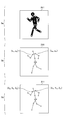
- FIG. 2 is a first diagram illustrating an outline of processing by the image analysis service providing unit.
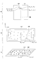
- FIG. 3 is a second diagram illustrating an outline of processing by the image analysis service providing unit.
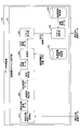
- FIG. 4 is a third diagram illustrating an outline of processing by the image analysis service providing unit.
- FIG. 5 is a diagram showing an example of the hardware configuration of the data processing device.
- FIG. 6 is a first diagram showing an example of the functional configuration of the image analysis service providing unit.
- FIG. 7 is a diagram for explaining the details of the conversion process.
- FIG. 8 is a first flowchart showing the flow of the image analysis service providing process.
- FIG. 9 is a second diagram showing an example of the functional configuration of the image analysis service providing unit.
- FIG. 10 is a second flowchart showing the flow of the image analysis service providing process.
- FIG. 1 is a diagram showing an example of a system configuration of an image distribution system.
- the image distribution system 100 of the present embodiment includes image pickup devices 110_1 to 110_n, an image data distribution device 120, a data processing device 140, and a terminal 150.
- the image data distribution device 120, the data processing device 140, and the terminal 150 are communicably connected via the network 130.
- the image pickup devices 110_1 to 110_n are two-dimensional cameras that take a bird's-eye view of the entire stadium (field) of a group competition (for example, soccer, rugby, American football, etc.).
- the image data obtained by the image pickup devices 110_1 to 110_n is transmitted to the image data distribution device 120.
- the imaging positions of the imaging devices 110_1 to 110_n (three-dimensional coordinate data in the world coordinate system (three-dimensional coordinates) which is an example of the second coordinate system) and the imaging directions (elevation / depression angle, azimuth angle) of the imaging devices 110_1 to 110_n. ) Is a fixed and known value.
- the image data distribution device 120 stores image data transmitted from the image pickup devices 110_1 to 110_n. Further, the image data distribution device 120 extracts analysis target image data for which analysis is requested to the data processing device 140 from the accumulated image data, and transmits the image data to the data processing device 140. Further, the image data distribution device 120 receives the analyzed image data transmitted from the data processing device 140.
- the image data distribution device 120 distributes the accumulated image data and the received analyzed image data to the terminal 150, for example, in response to a request from the terminal 150.
- An image analysis service providing program is installed in the data processing device 140, and by executing the program, the data processing device 140 functions as an image analysis service providing unit 141.
- the image analysis service providing unit 141 provides an image analysis service. Specifically, the image analysis service providing unit 141 receives the analysis target image data requested to be analyzed by the image data distribution device 120, and analyzes the received analysis target image data to generate the analyzed image data. To do. Further, the image analysis service providing unit 141 transmits the generated analyzed image data to the image data distribution device 120.
- the terminal 150 is a terminal used by a user who receives image data and analyzed image data, and is, for example, a personal computer, a smartphone, a tablet terminal, or the like.
- the terminal 150 receives the image data and the analyzed image data distributed from the image data distribution device 120 by making a distribution request for the image data or the like to the image data distribution device 120.
- the terminal 150 may include a display unit such as a display. As a result, the user of the terminal 150 can view the image data and the analyzed image data distributed from the image data distribution device 120.
- 2a in FIG. 2 shows a state in which a plurality of image pickup devices (in 2a in FIG. 2 show only four image pickup devices 110_1 to 110_4) take a bird's-eye view of the soccer stadium 200.
- the plurality of imaging devices may take a bird's-eye view of the entire stadium 200 as a shooting range from each shooting position, or may take a bird's-eye view of a part of the stadium 200 as a shooting range.
- 2b of FIG. 2 is a diagram showing an example of image data acquired by a predetermined imaging device (not shown in 2a of FIG. 2) taking a bird's-eye view of the entire stadium 200 from the lateral direction of the stadium 200. is there.
- the image data shown in 2b of FIG. 2 will be described as the analysis target image data 210 analyzed by the image analysis service providing unit 141.
- the image analysis service providing unit 141 first identifies the area of a person in the image data 210 to be analyzed, and extracts the extracted image data 211.
- 2c of FIG. 2 is an enlarged view of the extracted image data 211.
- the image analysis service providing unit 141 specifies the positions of the feature points corresponding to each part such as the head, shoulders, and hips of the person in the extracted image data 211.
- 3a in FIG. 3 shows how the positions (white circles) of the feature points corresponding to each part of the person in the extracted image data 211 are specified.
- the position of this feature point can be specified by, for example, image analysis.
- the skeleton of the target can be estimated by a trained model that can output the skeleton of the target by inputting an image showing the target, and a part of the obtained skeleton can be used as a feature point.
- the coordinate data of the position of the feature point corresponding to the left shoulder of the person (hereinafter, simply referred to as the position of the left shoulder) and the right shoulder of the person.
- the coordinate data of the position of the feature point corresponding to (hereinafter, simply referred to as the position of the right shoulder) is calculated.
- 3b of FIG. 3 shows that the coordinate data of the position of the left shoulder of the person was calculated as (x ls , y ls ) and the coordinate data of the position of the right shoulder of the person was calculated as (x rs , y rs ).
- these coordinate data two-dimensional coordinate data in the coordinate system (two-dimensional coordinates) of the image which is an example of the first coordinate system) have, for example, a predetermined position of the image data 210 to be analyzed as the origin in the lateral direction. Is defined as the x-axis and the vertical direction is defined as the y-axis.
- FIG. 3c of FIG. 3 shows how the calculated two-dimensional coordinate data is converted into the three-dimensional coordinate data of the world coordinate system. Specifically, it shows how the two-dimensional coordinate data of the position of the left shoulder of the person is converted into the three-dimensional coordinate data (X ls , Y ls , Z ls ) in the world coordinate system. It also shows how the two-dimensional coordinate data of the position of the right shoulder of the person is converted into the three-dimensional coordinate data (X rs , Y rs , Z rs ) in the world coordinate system.
- the image analysis service providing unit 141 uses the shooting position and shooting direction in the world coordinate system of the image pickup device that captures the analysis target image data 210 from a bird's-eye view to obtain the two-dimensional coordinate data on the analysis target image data 210 in the world. Convert to 3D coordinate data in the coordinate system. However, the details of the "conversion process" will be described later.
- the image analysis service providing unit 141 determines the orientation of the person's body (more specifically, based on the three-dimensional coordinate data of the position of the left shoulder of the person and the three-dimensional coordinate data of the position of the right shoulder of the person. Derivation of a vector representing the orientation of the person's chest).
- FIG. 4a of FIG. 4 shows how a vector representing the orientation of the human body is derived.
- -A surface that includes the position of the left shoulder of the person and the position of the right shoulder of the person, which is orthogonal to the surface parallel to the Z-axis direction and -Starting from the midpoint between the position of the person's left shoulder and the position of the person's right shoulder, ⁇ The end point is the front side of the person, and ⁇ Has a predetermined length Derivation of vector 400.
- three-dimensional coordinate data ((X ls , Y ls , Z ls ), (X rs , Y rs , Z rs )) of the positions of both shoulders of a person are used.
- -As three-dimensional coordinate data of the end point of the vector 400 (X v2 , Y v2 , Z v2 ), Indicates that was derived.
- the image analysis service providing unit 141 uses the vector 400 as image data of a predetermined region associated with the world coordinates (here, a top view of the entire stadium 200 as viewed from above.
- projected image data hereinafter, “projected image data”. (Called).
- FIG. 4b of FIG. 4 shows a state in which the vector 400 is projected onto the projected image data 410 which is a top view of the entire stadium 200 in which the world coordinates are associated with the positions of the pixels.
- the inverse conversion process opposite to the conversion process for converting the two-dimensional coordinate data to the three-dimensional coordinate data described in 3c of FIG. 3 is performed on the three-dimensional coordinate data of the start point and the end point of the vector 400, respectively.
- two-dimensional coordinate data (x v1 , y v1 ) and (x v2 , y v2 ) are calculated by performing an inverse conversion process on the three-dimensional coordinate data of the start point and the end point of the vector 400.
- the vector 400 is projected onto the image data 210 to be analyzed.
- a vector representing the orientation of the person's body can be identified.
- the vector 400 may be used for other purposes without being projected on the projected image data 410 or the analysis target image data 210.
- the vector 400 may be used as training data for another machine learning model.
- FIG. 5 is an example of the hardware configuration of the data processing device.
- the data processing device 140 of the present embodiment includes a processor 501, a memory unit 502, an auxiliary storage unit 503, an operation unit 504, a display unit 505, a communication unit 506, and a drive unit 507.
- the data processing device 140 is realized, for example, as a computer in which each of these components is connected via a bus 508.
- the data processing device 140 has one component for each, but the data processing device 140 may have a plurality of the same components. Further, in the example of FIG. 5, although the case where it is composed of one data processing device 140 is shown, it may be composed of a plurality of data processing devices. In this case, the software (for example, an image analysis service providing program) may be installed in the plurality of data processing devices, and each data processing device may be configured to execute different parts of the software. Further, in this case, each of the plurality of data processing devices may communicate with each other via a network interface or the like. Further, in the image pickup devices 110_1 to 110_n, the image data distribution device 120, the terminal 150, and the like, some processing performed by the data processing device 140 may be performed.
- the software for example, an image analysis service providing program
- the processor 501 is an electronic circuit (processing circuit, Processing circuitry) including an arithmetic unit such as a CPU (Central Processing Unit).
- the processor 501 performs arithmetic processing based on data and programs input from each component in the data processing device 140, and outputs an arithmetic result and a control signal to each component.
- the processor 501 controls each component in the data processing device 140 by executing an OS (Operating System), an application, or the like.
- OS Operating System
- the processor 501 is not limited to a specific processing circuit as long as it can perform the above processing.
- the processing circuit may refer to one or more electronic circuits arranged on one chip, or may refer to one or more electronic circuits arranged on two or more chips or devices. Good.
- each electronic circuit may communicate by wire or wirelessly.
- the memory unit 502 is a storage device that stores electronic information such as instructions and data executed by the processor 501.
- the electronic information stored in the memory unit 502 is directly read by the processor 501.
- the auxiliary storage unit 503 is a storage device other than the memory unit 502. Note that these storage devices refer to arbitrary electronic components that can store electronic information, and may be memory or storage. Further, the memory includes a volatile memory and a non-volatile memory, but any of them may be used.
- the memory for storing electronic information in the data processing device 140 may be realized by the memory unit 502 or the auxiliary storage unit 503.
- the operation unit 504 is an input device for the administrator of the data processing device 140 to input various instructions to the data processing device 140.
- the display unit 505 is a display device that displays the analyzed image data or the like obtained by the processor 501 executing the image analysis service providing program.
- the communication unit 506 is a communication device for connecting to the network 130 and communicating with the image data distribution device 120.
- the drive unit 507 is a device for setting the recording medium 510.
- the recording medium 510 referred to here includes a medium such as a CD-ROM, a flexible disk, a magneto-optical disk, or the like that optically, electrically, or magnetically records information. Further, the recording medium 510 may include a semiconductor memory or the like for electrically recording information such as a ROM or a flash memory.
- the various programs installed in the auxiliary storage unit 503 are installed, for example, by setting the distributed recording medium 510 in the drive unit 507 and reading the various programs recorded in the recording medium 510 by the drive unit 507. Will be done.
- various programs installed in the auxiliary storage unit 503 may be installed by being downloaded from the network 130.
- FIG. 6 is a diagram showing an example of the functional configuration of the image analysis service providing unit.
- the image analysis service providing unit 141 of the present embodiment includes an analysis target image data acquisition unit 610, a person area extraction unit 620, a site identification unit 630, a conversion unit 640, a vector calculation unit 650, and a vector projection unit. It has 660.
- the analysis target image data acquisition unit 610 acquires the analysis target image data (for example, the analysis target image data 210) requested to be analyzed by the image data distribution device 120. Further, the analysis target image data acquisition unit 610 notifies the person area extraction unit 620 of the acquired analysis target image data.
- the person area extraction unit 620 specifies the area of the person in the image data to be analyzed, and extracts the extracted image data (for example, the extracted image data 211) including the area of the specified person. In addition, the person area extraction unit 620 notifies the site identification unit 630 of the extracted extracted image data.
- the part identification part 630 is an example of the specific part, and specifies the position of the feature point corresponding to each part of the person in the extracted image data. Further, the site specifying unit 630 has two-dimensional coordinate data of the position of the feature point corresponding to the left shoulder of the person (position of the left shoulder) and the position of the feature point corresponding to the right shoulder of the person among the positions of the specified feature points. Calculate the two-dimensional coordinate data (position of the right shoulder). Further, the site identification unit 630 notifies the conversion unit 640 of the calculated two-dimensional coordinate data.
- the conversion unit 640 is an example of the first conversion unit, and is an image pickup device information storage unit that obtains the shooting position and shooting direction in the world coordinate system of the image pickup device that has taken a bird's-eye view of the analysis target image data for which the two-dimensional coordinate data has been calculated. Read from 670. Further, the conversion unit 640 uses the two-dimensional coordinate data of the position of the left shoulder of the person and the two-dimensional coordinate data of the position of the right shoulder of the person read out, such as the shooting position and the shooting direction, to be used in the world coordinate system. Convert to dimensional coordinate data.
- the conversion unit 640 notifies the vector calculation unit 650 of the three-dimensional coordinate data of the position of the left shoulder of the person and the three-dimensional coordinate data of the position of the right shoulder of the person.
- the vector calculation unit 650 is a vector (start point and end point in the world coordinate system) representing the orientation of the person's body based on the three-dimensional coordinate data of the position of the left shoulder of the person and the three-dimensional coordinate data of the position of the right shoulder of the person. 3D coordinate data) is derived. Further, the vector calculation unit 650 notifies the vector projection unit 660 of the derived vector (for example, the vector 400).
- the vector projection unit 660 is an example of an acquisition unit, and acquires information indicating the orientation of an object at a predetermined viewpoint (here, a vector indicating the orientation of a person's body). Specifically, the vector projection unit 660 reads out the projection image data (for example, the projection image data 410) stored in advance in the projection image storage unit 680, and projects the notified vector. Further, the vector projection unit 660 transmits the projected image data obtained by projecting the vector to the image data distribution device 120 as the analyzed image data.
- the projection image data for example, the projection image data 410
- the conversion unit 640 will explain the details of the "conversion process" for converting the two-dimensional coordinate data in the image data to be analyzed into the three-dimensional coordinate data in the world coordinate system.
- FIG. 7 is a diagram for explaining the details of the conversion process.
- the coordinate data (three-dimensional coordinate data in the world coordinate system) of the photographing position of the image pickup apparatus 110_n is (X Cn , Y Cn , Z Cn ). Further, it is assumed that the imaging direction (elevation / depression angle, azimuth angle) of the image pickup apparatus 110_n is ( ⁇ Cn , ⁇ Cn ).
- the site identification unit 630 calculates the two-dimensional coordinate data (x ls , y ls ) of the position of the left shoulder of the person.
- the direction (elevation / depression angle, azimuth) of the center position of the image data 210 to be analyzed as viewed from the shooting position (X Cn , Y Cn , Z Cn ) is ( ⁇ Cn , ⁇ Cn ). is there.
- the direction (elevation / depression angle, azimuth) of the left shoulder position of the person is based on the amount of deviation of the two-dimensional coordinate data (x ls , y ls ) of the position of the left shoulder of the person from the center position. Can be calculated (( ⁇ ls , ⁇ ls )).
- the site identification unit 630 obtains two-dimensional coordinate data (x rs , y rs ) of the position of the right shoulder of the person. calculate. Therefore, in the conversion unit 640, the direction (elevation / depression angle, azimuth) of the position of the right shoulder of the person is based on the amount of deviation from the center position of the two-dimensional coordinate data (x rs , y rs ) of the position of the right shoulder of the person. Angle) can be calculated (( ⁇ rs , ⁇ rs )).
- the image pickup device 110_n is extended from the shooting position (X Cn , Y Cn , Z Cn ) toward the position of the right shoulder of the person (( ⁇ rs , ⁇ rs )). Calculate the intersection of the line and the plane whose Z coordinate is Z s and parallel to the XY plane. As a result, the conversion unit 640 can calculate the X coordinate (X rs ) and the Y coordinate (Y rs ) of the position of the right shoulder of the person in the world coordinate system.
- the conversion unit 640 can convert the two-dimensional coordinate data in the analysis target image data into the three-dimensional coordinate data in the world coordinate system by a simple method (reconstructing the three-dimensional coordinate data). it can).
- the vector projection unit 660 can convert the vector representing the orientation of the person's body into an arbitrary viewpoint by using the three-dimensional coordinate data. That is, in the vector projection unit 660, the vector representing the direction of the body of the person can be easily specified by the projected image data of various viewpoints.
- FIG. 8 is a first flowchart showing the flow of the image analysis service providing process.
- step S801 the analysis target image data acquisition unit 610 acquires the analysis target image data.
- step S802 the person area extraction unit 620 inputs "1" to the counter i that counts the frames included in the image data to be analyzed.
- step S803 the person area extraction unit 620 identifies the person area in the i-frame and extracts the extracted image data including the specified person area.
- step S804 the part identification unit 630 specifies the position of the feature point corresponding to each part of the person in the extracted image data, and calculates the two-dimensional coordinate data of the positions of the left shoulder and the right shoulder.
- step S805 the conversion unit 640 converts the two-dimensional coordinate data of the positions of the left shoulder and the right shoulder into the three-dimensional coordinate data in the world coordinate system.
- step S806 the vector calculation unit 650 derives a vector (vector based on the positions of both shoulders) representing the orientation of the person's body by using the three-dimensional coordinate data of the positions of the left shoulder and the right shoulder.
- step S807 the person area extraction unit 620 determines whether or not a vector based on the positions of both shoulders has been derived for all the extracted image data extracted from the i-frame. If it is determined in step S807 that there is extracted image data for which the vector based on the positions of both shoulders has not been derived (NO in step S807), the process returns to step S804.
- step S807 if it is determined in step S807 that a vector based on the positions of both shoulders has been derived for all the extracted image data extracted from the i-frame (if YES in step S807), the process proceeds to step S808. ..
- step S808 the vector projection unit 660 projects all the derived vectors onto the projected image data. Further, the vector projection unit 660 transmits the projected image data obtained by projecting the vector to the image data distribution device 120 as the analyzed image data.
- step S809 the person area extraction unit 620 determines whether or not the processing has been executed for all the frames included in the acquired image data to be analyzed. If it is determined in step S809 that there is a frame for which processing has not been executed (NO in step S809), the process proceeds to step S810.
- step S810 the person area extraction unit 620 increments the counter i and returns to step S803.
- step S809 if it is determined in step S809 that the processing has been executed for all the frames included in the acquired image data to be analyzed, the image analysis service providing processing is terminated.
- the data processing apparatus is -Identify the positions of the left and right shoulders of a person in the acquired image data to be analyzed. -Based on the position and direction in which the analysis target image data was acquired and the heights of the left and right shoulders of the person, the two-dimensional coordinate data of the positions of the left and right shoulders of the person specified in the analysis target image data can be obtained. , Convert to 3D coordinate data in the world coordinate system. -Based on the three-dimensional coordinate data of the positions of the left shoulder and the right shoulder of the person, a vector representing the orientation of the person's body is derived. -Acquire a vector at a predetermined viewpoint based on the three-dimensional coordinate data of the positions of the left shoulder and the right shoulder of the person.
- the position of the feature point corresponding to a predetermined part of the person in the analysis target image data (in the image) can be converted into three-dimensional coordinate data.
- the vector representing the orientation of the person's body, which is derived based on the position of the feature point can be specified by the projected image data of various viewpoints.
- the first embodiment it is possible to provide a data processing device, an image distribution system, an image analysis method, and an image analysis program that can easily identify the direction of the target from the acquired image data.
- the second embodiment when the person is moving at a speed equal to or higher than a predetermined speed, a vector representing the direction of the person's body is derived based on the moving direction.
- the second embodiment will be described focusing on the differences from the first embodiment.
- FIG. 9 is a second diagram showing an example of the functional configuration of the image analysis service providing unit.
- the image analysis service providing unit 141 of the data processing device 140 according to the first embodiment is referred to as the image analysis service providing unit 141.
- a point having a movement vector calculation unit 910, -A point having a conversion unit 920, -The function of the vector projection unit 930 is different from the function of the vector projection unit 660. Is different.
- the movement vector calculation unit 910 is an example of the calculation unit. In each frame (time-series image data) included in the image data to be analyzed, a person's area is specified, and the extracted image data including the specified person's area is extracted. To do. Further, the movement vector calculation unit 910 calculates the position of the extracted extracted image data (two-dimensional coordinate data) and compares it with the position of the corresponding extracted image data (two-dimensional coordinate data) in the previous frame. As a result, the movement vector calculation unit 910 can calculate a movement vector (two-dimensional coordinate data) representing the distance and direction in which the person moves (during one frame period) while a predetermined time elapses.
- the movement vector calculation unit 910 calculates the movement vector for all the persons included in the frame, and also calculates the movement vector between all the frames included in the image data to be analyzed. Further, the movement vector calculation unit 910 notifies the conversion unit 920 of the calculated movement vector (two-dimensional coordinate data).
- the conversion unit 920 is an example of the second conversion unit, and reads out the shooting position and shooting direction in the world coordinate system of the image pickup device that has taken a bird's-eye view of the image data to be analyzed from the image pickup device information storage unit 670. Further, the conversion unit 920 converts the calculated movement vector (two-dimensional coordinate data of the start point and the end point) into three-dimensional coordinate data in the world coordinate system by using the read shooting position, shooting direction, and the like. Further, the conversion unit 920 notifies the vector projection unit 930 of the converted movement vector (three-dimensional coordinate data of the start point and the end point).
- the vector projection unit 930 acquires a vector (three-dimensional coordinate data) based on the positions of both shoulders derived by the vector calculation unit 650 and a movement vector (three-dimensional coordinate data) converted by the conversion unit 920.
- the vector projection unit 930 determines whether or not the movement vector (three-dimensional coordinate data) converted by the conversion unit 920 has a predetermined length (that is, the person moves at a speed equal to or higher than a predetermined speed). Whether or not) is determined.
- the vector projection unit 930 is converted by the conversion unit 920 when the converted movement vector has a predetermined length (when the person is moving at a speed equal to or higher than a predetermined speed).
- the created movement vector (three-dimensional coordinate data) is projected onto the projected image data.
- the vector projection unit 930 uses the vector calculation unit 650. The derived vector based on the positions of both shoulders is projected onto the projected image data.
- FIG. 10 is a second flowchart showing the flow of the image analysis service providing process.
- the differences from the image analysis service providing process shown in FIG. 8 are steps S1001 to S1006 and S1007.
- step S1001 the movement vector calculation unit 910 specifies the area of the person in the i-frame and extracts the extracted image data including the area of the specified person. Further, the movement vector calculation unit 910 calculates the two-dimensional coordinate data of the extracted extracted image data.
- step S1002 the movement vector calculation unit 910 acquires the two-dimensional coordinate data of the corresponding extracted image data calculated in the (i-1) th frame.
- step S1003 the movement vector calculation unit 910 calculates the movement vector (two-dimensional coordinate data) of the specified person based on the two-dimensional coordinate data calculated in step S1001 and the two-dimensional coordinate data acquired in step S1002. To do. Further, the conversion unit 920 converts the calculated movement vector (two-dimensional coordinate data) into three-dimensional coordinate data in the world coordinate system.
- step S1004 the vector projection unit 930 determines whether or not the movement vector converted in step S1003 has a predetermined length. If it is determined in step S1004 that the converted movement vector does not have a predetermined length (NO in step S1004), the process proceeds to step S1005.
- step S1005 the vector projection unit 930 selects the vector based on the positions of both shoulders derived in step S806 as the vector to be projected onto the projected image data.
- step S1004 determines whether the converted movement vector has a predetermined length (YES in step S1004). If it is determined in step S1004 that the converted movement vector has a predetermined length (YES in step S1004), the process proceeds to step S1006.
- step S1006 the vector projection unit 930 selects the moving vector converted in step S1003 as a vector to be projected onto the projected image data.
- step S1007 the vector projection unit 930 projects the vector selected in step S1005 or step S1006 onto the projected image data by using the three-dimensional coordinate data. Further, the vector projection unit 930 transmits the projected image data obtained by projecting the selected vector to the image data distribution device 120 as the analyzed image data.
- the data processing device has the functions of the data processing device according to the first embodiment in addition to the functions of the data processing device.
- the movement vector of the person between each frame is calculated and converted into three-dimensional coordinate data in the world coordinate system.
- the converted movement vector has a predetermined length, it is converted into the projected image data which is the top view associated with the world coordinates instead of the vector based on the positions of both shoulders. Project the movement vector.
- the data processing apparatus when the person is moving at a speed equal to or higher than a predetermined speed, the moving direction (without calculating the three-dimensional coordinate data of the positions of both shoulders). Based on, it is possible to derive a vector representing the orientation of the person's body. As a result, according to the second embodiment, the processing load of the data processing apparatus can be reduced.
- the specific realization method of the person area extraction unit 620 and the part identification unit 630 is not mentioned, but the person area extraction unit 620 and the part identification unit 630 input an image, for example. It may be realized by a trained model that obtains the required output as appropriate.
- the first embodiment it has been described as deriving a vector representing the orientation of the body of a person as a vector based on the positions of both shoulders.
- the information derived by the data processing device 140 based on the positions of both shoulders is not limited to the vector representing the orientation of the person's body, and information other than the vector representing the orientation of the person's body may be derived.
- the positions of both shoulders are used in deriving the vector representing the orientation of the body of the person.
- the positions of parts other than the positions of both shoulders may be used. For example, by using the positions of the abdomen under both shoulders in addition to the positions of both shoulders and calculating a vector orthogonal to the plane composed of three points, a vector representing the orientation of the person's body is derived. You may.
- the Z coordinate in the world coordinate system is assumed to be "Z s ".
- a database in which the shoulder height position is registered for each person in advance may be retained.
- the person is specified, and then the shoulder height position of the specified person is read from the database. May be good.
- the X and Y coordinates of the shoulder position of the specified person in the world coordinate system can be calculated with high accuracy.
- the positions of both shoulders of the person in the image data to be analyzed have been calculated.
- the position in the analysis target image data calculated by the data processing device 140 is not limited to the positions of both shoulders of the person, and may be the positions of other parts of the person.
- the positions of the left and right ears of the person, the positions of the left and right hips of the person, the positions of the left and right knees of the person, and the like may be calculated.
- a vector representing the direction of the person's face can be derived
- a vector representing the direction of the foot. Etc. can be derived.
- it is assumed that the position (Z coordinate in the world coordinate system) of the portion to be calculated in the height direction is preset in the conversion unit 640.
- the shooting position and the shooting direction of the image pickup device are fixed values, and the shooting position and the shooting direction of the image pickup device are read out from the image pickup device information storage unit 670.
- the shooting direction of the image pickup device is variable, it is assumed that the shooting direction of the image pickup device is associated with each frame included in the analysis target image data as incidental information.
- the conversion unit 640 may be configured to read the shooting direction by referring to the incidental information.
- the top view of the entire stadium 200 viewed from above is used as the projected image data, but the bird's-eye view seen from any viewpoint other than the top view may be used as the projected image data.
- one imaging device takes a bird's-eye view of the entire stadium 200 as a shooting range.
- a plurality of imaging devices take a bird's-eye view of a part of the area of the stadium 200 as a photographing range, they represent the orientation of each person's body derived for the person included in each area.
- the vector is projected onto the projected image data of 1. Thereby, the orientation of all the athletes in the stadium 200 can be specified.
- soccer is taken as an example as a group competition, but it goes without saying that it can be applied to group competitions other than soccer.
- the area of taking a bird's-eye view is not limited to the stadium. You may take a bird's-eye view of the place where the crowd is (the area where a large number of people are gathering). As a result, the data processing device 140 can perform crowd control.
- the terminal 150 receives the image data and the analyzed image data by requesting the image data distribution device 120.
- the terminal 150 may be configured to receive the analyzed image data by requesting the data processing device 140.
- the functions of the image analysis service providing units 141 and 900 have been described as being realized by the processor 501 executing the image analysis service providing program.
- the functions of the image analysis service providing units 141 and 900 may be realized by a circuit composed of an analog circuit, a digital circuit, or an analog / digital mixed circuit.
- a control circuit that realizes the functions of the image analysis service providing units 141 and 900 may be provided.
- the mounting of each circuit may be by ASIC (Application Specific Integrated Circuit), FPGA (Field Programmable Gate Array) or the like.
- the image analysis service providing program when executed, the image analysis service providing program is stored in a recording medium such as a flexible disk or a CD-ROM, read by a computer, and executed. May be good.
- the recording medium is not limited to a removable one such as a magnetic disk or an optical disk, and may be a fixed recording medium such as a hard disk device or a memory.
- the processing by software may be implemented in a circuit such as FPGA and executed by hardware.
Landscapes
- Engineering & Computer Science (AREA)
- Physics & Mathematics (AREA)
- General Physics & Mathematics (AREA)
- Theoretical Computer Science (AREA)
- Health & Medical Sciences (AREA)
- Computer Vision & Pattern Recognition (AREA)
- Multimedia (AREA)
- General Health & Medical Sciences (AREA)
- Life Sciences & Earth Sciences (AREA)
- Human Computer Interaction (AREA)
- Social Psychology (AREA)
- Psychiatry (AREA)
- Computational Linguistics (AREA)
- Software Systems (AREA)
- Oral & Maxillofacial Surgery (AREA)
- Molecular Biology (AREA)
- Biophysics (AREA)
- Pathology (AREA)
- Biomedical Technology (AREA)
- Heart & Thoracic Surgery (AREA)
- Medical Informatics (AREA)
- Dentistry (AREA)
- Surgery (AREA)
- Animal Behavior & Ethology (AREA)
- Public Health (AREA)
- Veterinary Medicine (AREA)
- Image Analysis (AREA)
- Measurement Of The Respiration, Hearing Ability, Form, And Blood Characteristics Of Living Organisms (AREA)
- Length Measuring Devices By Optical Means (AREA)
Priority Applications (1)
| Application Number | Priority Date | Filing Date | Title |
|---|---|---|---|
| US17/455,258 US20220076442A1 (en) | 2019-05-21 | 2021-11-17 | Data processing apparatus, image analysis method, and recording medium |
Applications Claiming Priority (2)
| Application Number | Priority Date | Filing Date | Title |
|---|---|---|---|
| JP2019095414A JP2020188914A (ja) | 2019-05-21 | 2019-05-21 | データ処理装置、画像配信システム、画像解析方法及び画像解析プログラム |
| JP2019-095414 | 2019-05-21 |
Related Child Applications (1)
| Application Number | Title | Priority Date | Filing Date |
|---|---|---|---|
| US17/455,258 Continuation US20220076442A1 (en) | 2019-05-21 | 2021-11-17 | Data processing apparatus, image analysis method, and recording medium |
Publications (1)
| Publication Number | Publication Date |
|---|---|
| WO2020235527A1 true WO2020235527A1 (ja) | 2020-11-26 |
Family
ID=73453022
Family Applications (1)
| Application Number | Title | Priority Date | Filing Date |
|---|---|---|---|
| PCT/JP2020/019649 Ceased WO2020235527A1 (ja) | 2019-05-21 | 2020-05-18 | データ処理装置、画像配信システム、画像解析方法及び画像解析プログラム |
Country Status (3)
| Country | Link |
|---|---|
| US (1) | US20220076442A1 (https=) |
| JP (1) | JP2020188914A (https=) |
| WO (1) | WO2020235527A1 (https=) |
Families Citing this family (1)
| Publication number | Priority date | Publication date | Assignee | Title |
|---|---|---|---|---|
| JP7433504B1 (ja) | 2023-06-13 | 2024-02-19 | 株式会社サイバーエージェント | 判定装置、判定方法及びコンピュータープログラム |
Citations (3)
| Publication number | Priority date | Publication date | Assignee | Title |
|---|---|---|---|---|
| JP2002197463A (ja) * | 2000-12-26 | 2002-07-12 | Matsushita Electric Ind Co Ltd | 挙動検出装置および挙動検出システム |
| WO2012077286A1 (ja) * | 2010-12-09 | 2012-06-14 | パナソニック株式会社 | 物体検出装置および物体検出方法 |
| JP2016054450A (ja) * | 2014-09-04 | 2016-04-14 | 株式会社東芝 | 画像処理装置、画像処理システム、画像処理方法及びプログラム |
Family Cites Families (8)
| Publication number | Priority date | Publication date | Assignee | Title |
|---|---|---|---|---|
| JP2967086B1 (ja) * | 1998-09-25 | 1999-10-25 | 株式会社エイ・ティ・アール知能映像通信研究所 | 多眼画像処理による人物の三次元姿勢推定方法 |
| JP2006323127A (ja) * | 2005-05-19 | 2006-11-30 | Univ Waseda | 画像投影システム、画像処理装置及び画像処理プログラム |
| JP2012123667A (ja) * | 2010-12-09 | 2012-06-28 | Panasonic Corp | 姿勢推定装置および姿勢推定方法 |
| JP6334925B2 (ja) * | 2013-01-18 | 2018-05-30 | キヤノンメディカルシステムズ株式会社 | 動作情報処理装置及び方法 |
| CN106296720B (zh) * | 2015-05-12 | 2019-01-25 | 株式会社理光 | 基于双目相机的人体朝向识别方法和系统 |
| EP3611691B1 (en) * | 2017-04-10 | 2021-04-21 | Fujitsu Limited | Recognition device, recognition system, recognition method, and recognition program |
| JP6853156B2 (ja) * | 2017-09-29 | 2021-03-31 | 株式会社日立製作所 | 姿勢推定システム、姿勢推定装置、及び距離画像カメラ |
| JP2021140196A (ja) * | 2018-05-31 | 2021-09-16 | ソニーグループ株式会社 | 情報処理装置、情報処理方法、及びプログラム |
-
2019
- 2019-05-21 JP JP2019095414A patent/JP2020188914A/ja active Pending
-
2020
- 2020-05-18 WO PCT/JP2020/019649 patent/WO2020235527A1/ja not_active Ceased
-
2021
- 2021-11-17 US US17/455,258 patent/US20220076442A1/en not_active Abandoned
Patent Citations (3)
| Publication number | Priority date | Publication date | Assignee | Title |
|---|---|---|---|---|
| JP2002197463A (ja) * | 2000-12-26 | 2002-07-12 | Matsushita Electric Ind Co Ltd | 挙動検出装置および挙動検出システム |
| WO2012077286A1 (ja) * | 2010-12-09 | 2012-06-14 | パナソニック株式会社 | 物体検出装置および物体検出方法 |
| JP2016054450A (ja) * | 2014-09-04 | 2016-04-14 | 株式会社東芝 | 画像処理装置、画像処理システム、画像処理方法及びプログラム |
Also Published As
| Publication number | Publication date |
|---|---|
| JP2020188914A (ja) | 2020-11-26 |
| US20220076442A1 (en) | 2022-03-10 |
Similar Documents
| Publication | Publication Date | Title |
|---|---|---|
| US10657366B2 (en) | Information processing apparatus, information processing method, and storage medium | |
| US12141916B2 (en) | Markerless motion capture of hands with multiple pose estimation engines | |
| KR20160098560A (ko) | 동작 분석 장치 및 방법 | |
| JP2012120647A (ja) | 姿勢検出装置 | |
| JP7501543B2 (ja) | 情報処理装置、情報処理方法及び情報処理プログラム | |
| CN108778123A (zh) | 步态分析装置、步态分析方法和计算机可读记录介质 | |
| JP7792532B2 (ja) | データ処理方法、データ処理装置、コンピュータ機器、及びコンピュータプログラム | |
| WO2009061283A2 (en) | Human motion analysis system and method | |
| CN109448105A (zh) | 基于多深度图像传感器的三维人体骨架生成方法及系统 | |
| JP7103998B2 (ja) | 骨格抽出方法、装置およびプログラム | |
| WO2017113674A1 (zh) | 基于智能设备实现体感控制的方法、系统以及智能设备 | |
| WO2020235527A1 (ja) | データ処理装置、画像配信システム、画像解析方法及び画像解析プログラム | |
| WO2023020327A1 (zh) | 图像处理 | |
| Ismail et al. | The applications of Microsoft Kinect for human motion capture and analysis: A review | |
| JP6839116B2 (ja) | 学習装置、推定装置、学習方法、推定方法及びコンピュータプログラム | |
| JP5559749B2 (ja) | 位置検出装置、位置検出方法及びコンピュータプログラム | |
| US20200226787A1 (en) | Information processing apparatus, information processing method, and program | |
| JP7629097B2 (ja) | 画像または映像におけるオブジェクトの3次元場所特定 | |
| CN116456039A (zh) | 视频合成方法、装置及系统 | |
| CA3172247C (en) | Markerless motion capture of hands with multiple pose estimation engines | |
| JP2019219988A (ja) | 意味情報付与装置、意味情報付与方法、およびプログラム | |
| CN118570345A (zh) | 虚拟对象驱动系统、方法、存储介质及电子设备 | |
| JP2021092891A (ja) | 情報処理装置、情報処理方法、画像処理システム及びプログラム | |
| HK40098476A (zh) | 数据处理方法、装置、设备以及介质 | |
| HK40098476B (zh) | 数据处理方法、装置、设备以及介质 |
Legal Events
| Date | Code | Title | Description |
|---|---|---|---|
| 121 | Ep: the epo has been informed by wipo that ep was designated in this application |
Ref document number: 20808925 Country of ref document: EP Kind code of ref document: A1 |
|
| NENP | Non-entry into the national phase |
Ref country code: DE |
|
| 122 | Ep: pct application non-entry in european phase |
Ref document number: 20808925 Country of ref document: EP Kind code of ref document: A1 |