WO2020235502A1 - 画像処理装置 - Google Patents
画像処理装置 Download PDFInfo
- Publication number
- WO2020235502A1 WO2020235502A1 PCT/JP2020/019511 JP2020019511W WO2020235502A1 WO 2020235502 A1 WO2020235502 A1 WO 2020235502A1 JP 2020019511 W JP2020019511 W JP 2020019511W WO 2020235502 A1 WO2020235502 A1 WO 2020235502A1
- Authority
- WO
- WIPO (PCT)
- Prior art keywords
- texture
- image
- biological information
- subject
- display
- Prior art date
Links
Images


Classifications
-
- A—HUMAN NECESSITIES
- A61—MEDICAL OR VETERINARY SCIENCE; HYGIENE
- A61B—DIAGNOSIS; SURGERY; IDENTIFICATION
- A61B1/00—Instruments for performing medical examinations of the interior of cavities or tubes of the body by visual or photographical inspection, e.g. endoscopes; Illuminating arrangements therefor
- A61B1/00002—Operational features of endoscopes
- A61B1/00004—Operational features of endoscopes characterised by electronic signal processing
- A61B1/00009—Operational features of endoscopes characterised by electronic signal processing of image signals during a use of endoscope
- A61B1/000094—Operational features of endoscopes characterised by electronic signal processing of image signals during a use of endoscope extracting biological structures
-
- G—PHYSICS
- G06—COMPUTING; CALCULATING OR COUNTING
- G06T—IMAGE DATA PROCESSING OR GENERATION, IN GENERAL
- G06T11/00—2D [Two Dimensional] image generation
- G06T11/001—Texturing; Colouring; Generation of texture or colour
-
- A—HUMAN NECESSITIES
- A61—MEDICAL OR VETERINARY SCIENCE; HYGIENE
- A61B—DIAGNOSIS; SURGERY; IDENTIFICATION
- A61B1/00—Instruments for performing medical examinations of the interior of cavities or tubes of the body by visual or photographical inspection, e.g. endoscopes; Illuminating arrangements therefor
- A61B1/04—Instruments for performing medical examinations of the interior of cavities or tubes of the body by visual or photographical inspection, e.g. endoscopes; Illuminating arrangements therefor combined with photographic or television appliances
- A61B1/045—Control thereof
-
- G—PHYSICS
- G06—COMPUTING; CALCULATING OR COUNTING
- G06T—IMAGE DATA PROCESSING OR GENERATION, IN GENERAL
- G06T7/00—Image analysis
- G06T7/0002—Inspection of images, e.g. flaw detection
- G06T7/0012—Biomedical image inspection
-
- G—PHYSICS
- G06—COMPUTING; CALCULATING OR COUNTING
- G06T—IMAGE DATA PROCESSING OR GENERATION, IN GENERAL
- G06T7/00—Image analysis
- G06T7/40—Analysis of texture
-
- G—PHYSICS
- G06—COMPUTING; CALCULATING OR COUNTING
- G06T—IMAGE DATA PROCESSING OR GENERATION, IN GENERAL
- G06T7/00—Image analysis
- G06T7/90—Determination of colour characteristics
-
- A—HUMAN NECESSITIES
- A61—MEDICAL OR VETERINARY SCIENCE; HYGIENE
- A61B—DIAGNOSIS; SURGERY; IDENTIFICATION
- A61B1/00—Instruments for performing medical examinations of the interior of cavities or tubes of the body by visual or photographical inspection, e.g. endoscopes; Illuminating arrangements therefor
- A61B1/00002—Operational features of endoscopes
- A61B1/00043—Operational features of endoscopes provided with output arrangements
- A61B1/00045—Display arrangement
-
- G—PHYSICS
- G06—COMPUTING; CALCULATING OR COUNTING
- G06T—IMAGE DATA PROCESSING OR GENERATION, IN GENERAL
- G06T2207/00—Indexing scheme for image analysis or image enhancement
- G06T2207/10—Image acquisition modality
- G06T2207/10024—Color image
-
- G—PHYSICS
- G06—COMPUTING; CALCULATING OR COUNTING
- G06T—IMAGE DATA PROCESSING OR GENERATION, IN GENERAL
- G06T2207/00—Indexing scheme for image analysis or image enhancement
- G06T2207/10—Image acquisition modality
- G06T2207/10068—Endoscopic image
-
- G—PHYSICS
- G06—COMPUTING; CALCULATING OR COUNTING
- G06T—IMAGE DATA PROCESSING OR GENERATION, IN GENERAL
- G06T2207/00—Indexing scheme for image analysis or image enhancement
- G06T2207/10—Image acquisition modality
- G06T2207/10072—Tomographic images
- G06T2207/10081—Computed x-ray tomography [CT]
-
- G—PHYSICS
- G06—COMPUTING; CALCULATING OR COUNTING
- G06T—IMAGE DATA PROCESSING OR GENERATION, IN GENERAL
- G06T2207/00—Indexing scheme for image analysis or image enhancement
- G06T2207/10—Image acquisition modality
- G06T2207/10072—Tomographic images
- G06T2207/10088—Magnetic resonance imaging [MRI]
-
- G—PHYSICS
- G06—COMPUTING; CALCULATING OR COUNTING
- G06T—IMAGE DATA PROCESSING OR GENERATION, IN GENERAL
- G06T2207/00—Indexing scheme for image analysis or image enhancement
- G06T2207/10—Image acquisition modality
- G06T2207/10116—X-ray image
-
- G—PHYSICS
- G06—COMPUTING; CALCULATING OR COUNTING
- G06T—IMAGE DATA PROCESSING OR GENERATION, IN GENERAL
- G06T2207/00—Indexing scheme for image analysis or image enhancement
- G06T2207/10—Image acquisition modality
- G06T2207/10132—Ultrasound image
-
- G—PHYSICS
- G06—COMPUTING; CALCULATING OR COUNTING
- G06T—IMAGE DATA PROCESSING OR GENERATION, IN GENERAL
- G06T2207/00—Indexing scheme for image analysis or image enhancement
- G06T2207/30—Subject of image; Context of image processing
- G06T2207/30004—Biomedical image processing
- G06T2207/30096—Tumor; Lesion
-
- G—PHYSICS
- G06—COMPUTING; CALCULATING OR COUNTING
- G06T—IMAGE DATA PROCESSING OR GENERATION, IN GENERAL
- G06T2207/00—Indexing scheme for image analysis or image enhancement
- G06T2207/30—Subject of image; Context of image processing
- G06T2207/30004—Biomedical image processing
- G06T2207/30101—Blood vessel; Artery; Vein; Vascular
-
- G—PHYSICS
- G06—COMPUTING; CALCULATING OR COUNTING
- G06T—IMAGE DATA PROCESSING OR GENERATION, IN GENERAL
- G06T2210/00—Indexing scheme for image generation or computer graphics
- G06T2210/41—Medical
Definitions
- the present invention relates to an image processing device that performs image processing using a medical image such as an endoscopic image.
- the endoscope system is, for example, an endoscope (so-called scope) inserted into a subject, a light source device that generates illumination light for illuminating the subject, and a processor device that acquires an endoscope image of the subject using the endoscope. , And a monitor or the like for displaying an endoscopic image or the like.
- an endoscopic system has been known that not only photographs a subject naturally but also calculates and displays biological information of the subject using an endoscopic image.
- an endoscope system in which a pseudo-color image showing a hemoglobin index value is superimposed on a so-called region of interest (Patent Document 1).
- endoscopic systems that display a part of a region such as a region where the oxygen saturation is below a certain value in pseudo color (Patent Documents 2 and 3).
- an endoscope system in which the saturation is set low in a region where a large displacement is large when the oxygen saturation is displayed in pseudo color (Patent Document 4).
- An endoscope system that changes the display mode according to the reliability indicating the certainty of setting the region of interest is also known (Patent Document 5).
- An object of the present invention is to provide an image processing device that shows biological information in a manner that clearly shows that the biological information is shown when the biological information is shown on an image.
- the image processing device of the present invention is an image processing device including a processor, and the processor acquires an endoscopic image of a subject and generates an endoscopic image or an endoscopic image for display. Using an image, biological information related to a subject is calculated, a plurality of textures representing the biological information are superimposed on an endoscopic image or a display image, and boundaries of adjacent textures are shown.
- the processor preferably provides a gap between adjacent textures.
- the texture preferably has a size of 2 pixels or more.
- the processor superimposes a texture having a color corresponding to biological information on the endoscopic image or the display image.
- the processor superimposes a texture having a size corresponding to the biological information on the endoscopic image or the display image.
- the processor preferably superimposes a texture having a shape corresponding to biological information on an endoscopic image or a display image.
- the processor superimposes the texture on the part that satisfies the specific condition and does not superimpose the texture on the part that does not satisfy the specific condition.
- the processor superimposes the texture on the portion where the difference or ratio between the reference value defined for the biometric information and the calculated biometric information value satisfies a specific condition.
- the processor preferably superimposes the texture on the portion where the rate of change of biological information is equal to or higher than the reference value.
- the processor sets the position where the texture can be superimposed at a fixed position with respect to the endoscopic image or the display image.
- the processor preferably sets an upper limit value for the area on which the texture can be superimposed, and superimposes the texture within a range in which the area of the area on which the texture is superimposed is equal to or less than the upper limit value.
- the processor When the movement of the subject of the endoscope image or the display image stops, or when the movement of the endoscope that captures the endoscope image or the display image stops, the processor superimposes the texture. It is preferable to stop.
- the biological information when the biological information is shown on the image, the biological information can be shown in a manner that clearly shows that the biological information is shown.
- the endoscope system 10 includes an endoscope 12 (scope), a light source device 14, a processor device 16, a monitor 18, and a console 19.
- the endoscope 12 photographs a subject.
- the light source device 14 generates illumination light.
- the processor device 16 controls the system of the endoscope system 10. Further, the processor device 16 generates an endoscopic image and performs image processing on the endoscopic image as needed. That is, the processor device 16 functions as an image processing device.
- the monitor 18 is a display unit that displays an endoscopic image or the like.
- the console 19 is an input device for inputting settings to the processor device 16 and the like.
- the endoscope 12 includes an insertion portion 12a to be inserted into the subject, an operation portion 12b provided at the base end portion of the insertion portion 12a, a curved portion 12c provided on the tip end side of the insertion portion 12a, and a tip portion 12d. ,have.
- the angle knob 12e of the operation unit 12b By operating the angle knob 12e of the operation unit 12b, the curved portion 12c is curved. As a result, the tip portion 12d faces in a desired direction.
- the operation unit 12b is provided with an angle knob 12e, a treatment tool insertion port 12f, and a zoom operation unit 13.
- the treatment tool insertion port 12f is an entrance for inserting a treatment tool such as a biopsy forceps, a snare, or an electric knife.
- the treatment tool inserted into the treatment tool insertion port 12f protrudes from the tip portion 12d.
- the zoom operation unit 13 By operating the zoom operation unit 13, the subject can be enlarged or reduced for shooting.
- the light source device 14 includes a light source unit 20 that emits illumination light and a light source control unit 22 that controls the operation of the light source unit 20.
- the light source unit 20 emits illumination light that illuminates the subject.
- the emission of the illumination light includes the emission of excitation light or the like used to emit the illumination light.
- the light source unit 20 includes, for example, a light source of a laser diode, an LED (Light Emitting Diode), a xenon lamp, or a halogen lamp, and is excited to be used to emit at least white illumination light or white illumination light. It emits light.
- White includes so-called pseudo-white, which is substantially equivalent to white in photographing a subject using the endoscope 12.
- the light source unit 20 includes, if necessary, a phosphor that emits light when irradiated with excitation light, an optical filter that adjusts the wavelength band, spectral spectrum, light amount, etc. of the illumination light or excitation light.
- the light source unit 20 can emit light having a specific wavelength band necessary for capturing an image used for calculating biological information such as oxygen saturation of hemoglobin contained in the subject.
- the light source unit 20 has four-color LEDs of V-LED20a, B-LED20b, G-LED20c, and R-LED20d.
- the V-LED 20a emits purple light VL having a center wavelength of 405 nm and a wavelength band of 380 to 420 nm.
- the B-LED 20b emits blue light BL having a center wavelength of 460 nm and a wavelength band of 420 to 500 nm.
- the G-LED 20c emits green light GL having a wavelength band of 480 to 600 nm.
- the R-LED20d emits red light RL having a center wavelength of 620 to 630 nm and a wavelength band of 600 to 650 nm.
- the center wavelengths of the V-LED 20a and the B-LED 20b have a width of about ⁇ 20 nm, preferably about ⁇ 5 nm to about ⁇ 10 nm.
- the light source control unit 22 controls the timing of turning on, off, or shielding each light source constituting the light source unit 20, the amount of light emitted, and the like.
- the light source unit 20 can emit a plurality of types of illumination light having different spectral spectra.
- the light source control unit 22 disperses the illumination light by inputting independent control signals for turning on / off the LEDs 20a to 20d, the amount of light emitted at the time of lighting, the insertion / removal of the optical filter, and the like. Adjust the spectrum.
- the light source unit 20 emits white light.
- the light source unit 20 can emit illumination light composed of at least narrow band light (hereinafter referred to as narrow band light).
- the “narrow band” means a substantially single wavelength band in relation to the characteristics of the subject and / or the spectral characteristics of the color filter of the image sensor 48.
- the wavelength band is, for example, about ⁇ 20 nm or less (preferably about ⁇ 10 nm or less)
- this light is a narrow band.
- the wide band means having a relatively wide wavelength band as compared with a narrow band light in relation to the characteristics of the subject and / or the spectral characteristics of the color filter of the image sensor 48. Therefore, when the wavelength band is, for example, ⁇ 20 nm or more, the light is a wide band light.
- the tip portion 12d of the endoscope 12 is provided with an illumination optical system 30a and a photographing optical system 30b.
- the illumination optical system 30a has an illumination lens 45, and the illumination light is emitted toward the subject through the illumination lens 45.
- the photographing optical system 30b includes an objective lens 46, a zoom lens 47, and an image sensor 48.
- the image sensor 48 uses the objective lens 46 and the zoom lens 47 to administer the reflected light of the illumination light returning from the subject (in addition to the reflected light, scattered light, fluorescence emitted by the subject, or to the subject).
- the subject is photographed using (including fluorescence caused by the same chemicals).
- the zoom lens 47 moves by operating the zoom operation unit 13 to enlarge or reduce the subject image.
- the image sensor 48 has a color filter of one of a plurality of color filters for each pixel.
- the image sensor 48 is a color sensor having a primary color system color filter.
- the image sensor 48 includes an R pixel having a red color filter (R filter), a G pixel having a green color filter (G filter), and a B pixel having a blue color filter (B filter).
- R filter red color filter
- G filter green color filter
- B filter blue color filter
- CMOS Complementary Metal Oxide Semiconductor
- the image sensor 48 of the present embodiment is a primary color system color sensor
- a complementary color system color sensor can also be used.
- Complementary color sensors include, for example, a cyan pixel provided with a cyan color filter, a magenta pixel provided with a magenta color filter, a yellow pixel provided with a yellow color filter, and a green pixel provided with a green color filter.
- the complementary color sensor is used, the image obtained from the pixels of each of the above colors can be converted into an image similar to the image obtained by the primary color sensor by performing complementary color-primary color conversion.
- the primary color system or complementary color system sensor has one or a plurality of types of pixels having characteristics other than the above, such as W pixels (white pixels that receive light in almost all wavelength bands).
- W pixels white pixels that receive light in almost all wavelength bands.
- the image sensor 48 of the present embodiment is a color sensor, a monochrome sensor having no color filter may be used.
- the processor device 16 includes a control unit 52 (processor).
- the control unit 52 is a hardware resource for executing a program instruction stored in a memory (not shown), and displays the processor device 16 as an image acquisition unit 54 and an image processing unit 61 in accordance with the execution of the program instruction. It functions as a control unit 66.
- the control unit 52 also causes the processor device 16 to function as an image generation unit 71, a biological information calculation unit 72, and a texture processing unit 73, which will be described later, in accordance with the execution of the program command.
- the control unit 52 comprehensively controls the endoscope system 10 such as synchronous control of the irradiation timing of the illumination light and the shooting timing.
- the control unit 52 sets the settings in each part of the endoscope system 10 such as the light source control unit 22, the image sensor 48, or the image processing unit 61. Enter in.
- the image acquisition unit 54 acquires an endoscopic image of the subject. More specifically, the image acquisition unit 54 acquires an image of a subject photographed using pixels of each color, that is, a RAW image, from the image sensor 48.
- the RAW image is an image (endoscopic image) before the demosaic process is performed. If it is an image before the demosaic processing is performed, the RAW image also includes an image obtained by performing arbitrary processing such as noise reduction processing on the image acquired from the image sensor 48.
- the image acquisition unit 54 includes a DSP (Digital Signal Processor) 56, a noise reduction unit 58, and a conversion unit 59 in order to perform various processing on the acquired RAW image as necessary to generate an endoscopic image. To be equipped.
- DSP Digital Signal Processor
- the DSP 56 includes, for example, an offset processing unit, a defect correction processing unit, a demosaic processing unit, a linear matrix processing unit, a YC conversion processing unit, and the like (none of which are shown).
- the DSP 56 performs various processing on a RAW image or an image generated by using the RAW image using these.
- the offset processing unit performs offset processing on the RAW image.
- the offset process is a process of reducing the dark current component from the RAW image and setting an accurate zero level.
- the offset process may be referred to as a clamp process.
- the defect correction processing unit performs defect correction processing on the RAW image.
- the defect correction process is a process of correcting or generating a pixel value of a RAW pixel corresponding to a defective pixel of the image sensor 48 when the image sensor 48 includes a pixel (defective pixel) having a defect due to a manufacturing process or a change with time. Is.
- the demosaic processing unit performs demosaic processing on the RAW image of each color corresponding to the color filter of each color.
- the demosaic process is a process of generating pixel values that are missing due to the arrangement of color filters in a RAW image by interpolation.
- the linear matrix processing unit performs linear matrix processing on the endoscopic image generated by assigning one or a plurality of RAW images to channels of each RGB color.
- the linear matrix processing is a processing for enhancing the color reproducibility of an endoscopic image.
- an endoscope image generated by assigning one or a plurality of RAW images to each RGB color channel is an endoscope having a brightness channel Y, a color difference channel Cb, and a color difference channel Cr. This is the process of converting to an image.
- the noise reduction unit 58 performs noise reduction processing on an endoscopic image having a luminance channel Y, a color difference channel Cb, and a color difference channel Cr by using, for example, a moving average method or a median filter method.
- the conversion unit 59 reconverts the luminance channel Y, the color difference channel Cb, and the color difference channel Cr after the noise reduction processing into an endoscopic image having channels of each color of BGR.
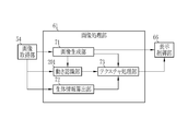
- the image processing unit 61 performs necessary image processing on the endoscopic image output by the image acquisition unit 54. Further, the image processing unit 61 performs an calculation using an endoscopic image output by the image acquisition unit 54 or another endoscopic image generated by using the endoscopic image output by the image acquisition unit 54. To do. Specifically, as shown in FIG. 3, the image processing unit 61 includes an image generation unit 71, a biological information calculation unit 72, a texture processing unit 73, and the like.
- the image generation unit 71 acquires an endoscope image from the image acquisition unit 54 and generates an endoscope image (hereinafter referred to as a display image) to be used for display on a monitor 18 or the like.
- the image generation unit 71 may use the image acquisition unit 54 to capture a B image of the subject using the B pixel, a G image of the subject photographed using the G pixel, and an R image of the subject using the R pixel. Images and images are acquired, and all or part of them are used to generate an image for display.
- the image acquisition unit 54 This includes performing and outputting the necessary image processing on one endoscopic image acquired from the image acquisition unit 54, and outputting the one endoscopic image acquired from the image acquisition unit 54 as it is.
- the image generation unit 71 generates a display image by using the endoscopic image acquired from the image acquisition unit 54 or the endoscopic image acquired from the image acquisition unit 54 when generating the display image. Is subjected to necessary image processing.
- the image processing performed by the image generation unit 71 is, for example, an enhancement process for emphasizing the subject or a part of the subject. Emphasis means making it possible to obtain information on a specific part by distinguishing it from other organizations or structures. For example, a process of surrounding a part having a specific feature with a frame to show an outline, or changing the color or brightness relative to another part (for example, normal mucous membrane) is an emphasis process. ..
- the biological information calculation unit 72 is an endoscopic image acquired from the image acquisition unit 54 and / or an endoscopic image generated by the image generation unit 71 using the endoscopic image acquired from the image acquisition unit 54.
- the biological information related to the subject is calculated using the display image.
- the biological information is a numerical value or the like representing the whole or partial characteristics of the subject, for example, oxygen saturation, blood concentration, blood vessel density, or a lesion or a candidate for a lesion (including a target for biological tissue examination) and the like. The certainty of having a specific form of.
- the biological information calculation unit 72 calculates the oxygen saturation of the subject for each pixel using the endoscopic image acquired from the image acquisition unit 54.
- oxygen saturation for example, a B image in which the subject is photographed using narrow-band light having a wavelength of about 470 nm, a G image in which the subject is photographed using wideband green light, and a wideband red light are used. It can be calculated using an R image obtained by photographing the subject. More specifically, the ratio of the B image to the G image (hereinafter referred to as B / G) and the ratio of the R image to the G image (hereinafter referred to as R / G) are obtained for each pixel.
- B / G the ratio of the B image to the G image
- R / G the ratio of the R image to the G image
- a table or the like for associating B / G and R / G with the oxygen saturation value by an experiment or a simulation is prepared in advance. Then, the oxygen saturation is calculated from the calculated B / G and R / G values using the above table.
- the biological information calculation unit 72 calculates the oxygen saturation
- the image acquisition unit 54 acquires each of these images and provides them to the biological information calculation unit 72.
- the texture processing unit 73 superimposes a plurality of textures representing biological information on the endoscopic image obtained from the image acquisition unit 54 or the display image generated by the image generation unit 71 (hereinafter referred to as a display image or the like).
- the texture processing unit 73 superimposes the texture on the endoscopic image, for example, when the endoscopic image is used for display or the like. That is, the object on which the texture processing unit 73 superimposes the texture is an image displayed on the monitor 18 or the like.
- the display image or the like on which the texture processing unit 73 superimposes the texture is referred to as a biological information image.
- the biological information image is an image (endoscopic image) that displays biological information by texture.
- Representing biological information is a mode of display directly based on the value of biological information calculated by the biological information calculation unit 72, or indirectly based on a numerical value calculated using biological information or the like.
- a texture is a figure or the like (including a case where it has the form of a character or a symbol) superimposed on a part of a display image or the like and has a specific pattern and / or shape (outline).
- the texture can be composed of lines (so-called hollow figures) representing the shapes of figures and the like. Further, since the texture has a gradation pattern whose color differs depending on the position, the shape may not be clearly recognized in the display image or the like.
- the texture used by the texture processing unit 73 is a quadrangular figure, and the tile texture 85 (see FIG. 4 and the like) in which the inside is colored.
- “Superimposing" a texture on a display image or the like means that at least when the display image or the like is displayed on a monitor 18 or the like, a subject whose texture features such as pattern, shape, and / or color are reflected in the display image or the like. It means to display the texture on the display image, etc. in a manner that can be distinguished and recognized. In addition to displaying the texture on the display image, etc. in a separable manner, the texture is combined (integrated) with the display image, etc. ) Including. In the present embodiment, the texture processing unit 73 superimposes the texture on the display image or the like in a separable manner.
- the texture processing unit 73 has a plurality of types of textures having different shapes, colors, patterns, or sizes, and one type of texture can be selected and used based on the settings and the like. Further, the texture processing unit 73 can use a plurality of types of textures in combination based on the settings and the like.
- the texture processing unit 73 determines the size, color (hue, lightness, saturation, etc.), brightness (luminance), and / or transparency of some or all elements of one texture. It can be changed and superimposed on a display image or the like. However, the texture processing unit 73 sets the size of each texture to at least two pixels or more of a display image or the like on which the texture is superimposed. This is to clarify the difference from the pixels of the display image or the like so that the texture can be recognized as the texture. Further, the texture processing unit 73 can superimpose and display at least two or more textures in the subject display area 83 (see FIG. 4) while making the size of one texture smaller than the display image or the like on which the textures are superimposed. Make it the size.
- the texture processing unit 73 changes the size, color, brightness, and / or transparency of each texture for display. It can be superimposed on an image or the like.
- the texture processing unit 73 when a plurality of textures are superposed on the display image or the like, the texture is superimposed on the display image or the like at adjacent positions (hereinafter, adjacent). It is an aspect showing the boundary of the texture).
- "Indicating a boundary” means displaying a pattern or shape of each texture in a display image or the like in a form that can be distinguished and perceived. For example, a mode in which a gap is provided between adjacent textures is a mode in which a boundary is provided.
- the texture processing unit 73 provides a gap between adjacent textures (see FIG. 4 and the like).
- the texture processing unit 73 determines a position where the texture can be superimposed at a fixed position with respect to the display image or the like. That is, the texture processing unit 73 predetermines the position on which the texture is superimposed according to the display size of the display image or the like, regardless of the shape of the subject or the like. Further, the texture processing unit 73 superimposes the texture on the portion that satisfies the specific condition, and does not superimpose the texture on the portion that does not satisfy the specific condition.
- the texture processing unit 73 determines a plurality of grid points that specify the position where the texture is superimposed on the display image or the like by setting or the like. Then, based on the biological information to be displayed, the texture is superimposed on a part or all of the required positions of the lattice points on which the texture can be superimposed. Further, the grid points defined by the texture processing unit 73 are determined independently of the shape of the subject. Then, the texture processing unit 73 does not change the position and distribution (density, etc.) of the grid points in the display image or the like depending on the change of the subject reflected in the display image or the like. That is, the position where the texture can be superimposed does not follow the change in the shape of the subject and is constant. However, whether or not the texture processing unit 73 superimposes the texture on each grid point depends on the change of the subject. This is because the value of the biological information calculated by the biological information calculation unit 72 changes according to the change of the subject.
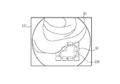
- the texture processing unit 73 sets grid points 82 in a square grid pattern with respect to the display image 81. Further, among these grid points 82, the grid point 82 in the subject display area 83 for displaying the subject is set as the texture superimposition position.
- the grid points 82 inside the subject display area 83 are indicated by filled circles ( ⁇ ), and the grid points 82 outside the subject display area 83 are indicated by hollow circles ( ⁇ ). ing.
- the arrangement (grid type) and density (or spacing) of the grid points 82 can be arbitrarily changed by setting or the like.
- the texture processing unit 73 may automatically change the size and / or shape of the texture according to the arrangement and density of the grid points 82. This is to properly show the boundaries between textures.
- the texture processing unit 73 aligns the center (center position) with the grid points 82 and superimposes the tile texture 85 on the display image 81. Further, the texture processing unit 73 provides a gap of ⁇ X in the X direction and a gap of ⁇ Y in the Y direction by adjusting the size of the tile texture 85.
- the gap in the X direction ( ⁇ X) and the gap in the Y direction ( ⁇ Y) may be equal or different.
- the gap in the X direction ( ⁇ X) and the gap in the Y direction ( ⁇ Y) are equal. This is to reduce the directionality of the gap between the tile textures 85 and prevent an unintended shape or pattern from appearing on the display image 81 due to the directionality of the gap between the tile textures 85.
- the texture processing unit 73 acquires biological information from the biological information calculation unit 72 and superimposes the texture on each grid point 82 by using the value of the acquired biological information or the numerical value calculated using the biological information. Whether or not it is determined for each grid point 82.
- the biological information calculation unit 72 calculates the oxygen saturation as biological information. Therefore, the texture processing unit 73 superimposes the texture on the portion of the region where the oxygen saturation is equal to or lower than the reference value (hereinafter referred to as the hypoxic region).
- the reference value is predetermined for each biological information according to the type of biological information. When the biological information is oxygen saturation, the reference value is, for example, 70%.
- the texture processing unit 73 uses the oxygen saturation value calculated by the biological information calculation unit 72 to form a predetermined region including each grid point 82 (for example, a so-called Wigner-Seitz cell of each grid point 82).
- the average value of oxygen saturation is calculated for the pixels belonging to, and the calculated average value is compared with a predetermined reference value. Then, when the average value of the oxygen saturation is equal to or less than the reference value, it is determined that the lattice point 82 belongs to the low oxygen region, and the texture is superimposed on the lattice point 82.
- the average value of oxygen saturation is larger than the reference value, it is determined that the grid point 82 belongs to the high oxygen region (the region where the oxygen saturation value is normal), and the grid point 82 is textured. Decide not to superimpose.
- the texture processing unit 73 calculates the average value of oxygen saturation, but instead of the average value, other statistics such as total value, median value, minimum value, variance, or standard deviation.
- the amount can be calculated and used for determining whether or not to superimpose the texture (hereinafter referred to as superimposition determination).
- a plurality of statistics can be calculated and combined to be used for superimposition determination.
- the texture processing unit 73 obtains, for example, the rate of change in oxygen saturation (for example, the gradient (differential value) of the distribution of oxygen saturation), and is a statistic about the rate of change in oxygen saturation or the rate of change in oxygen saturation. Can be used for superposition determination.
- the reference value is set in advance to a value that can be compared with the statistic used for determining whether or not to superimpose the texture. Further, when a plurality of statistics and / or calculated values such as a differential value are used for the superposition determination, a plurality of reference values may be set according to each statistic and the like.
- the display control unit 66 converts the display image or the like output by the image processing unit 61 into a format suitable for display and outputs it to the monitor 18. As a result, the monitor 18 displays the display image.
- the texture processing unit 73 superimposes a texture on a display image or the like
- the display control unit 66 acquires a biological information image from the texture processing unit 73 and outputs the biometric information image to the monitor 18.
- the image generation unit 71 acquires an endoscope image from the image acquisition unit 54 and uses the endoscope image.
- a display image 81 is generated (step S102).
- the endoscopic image acquired by the image generation unit 71 includes an endoscopic image used by the biological information calculation unit 72 for calculating biological information, in addition to the one used for generating the display image 81.
- the biological information calculation unit 72 acquires an endoscopic image from the image acquisition unit 54, and uses this to calculate the oxygen saturation, which is biological information, for each pixel (step S103).
- the texture processing unit 73 makes a superposition determination for each grid point 82 using the oxygen saturation calculated by the biological information calculation unit 72.
- the texture processing unit 73 superimposes the tile texture 85, which is one aspect of the texture, on the display image 81, for example, on the lattice points 82 belonging to the low oxygen region (step).
- the biological information image 91 is generated.
- the monitor 18 displays the biological information image 91 (step S105).
- the generation and display of the biological information image 91 uses the endoscope 12 to capture the subject while the subject is being photographed by the endoscope 12 unless the observation mode in which the biological information is calculated and displayed is switched to. Repeat each time you take a picture or intermittently.
- the endoscope system 10 calculates the biological information in the processor device 16 that functions as an image processing device, and displays the biological information using the biological information image 91 on which the texture is superimposed.
- the mode in which the textures are superimposed is a mode in which the boundaries of adjacent textures are indicated. Therefore, the endoscope system 10 can show the biological information in a manner that clearly shows that the biological information is shown. For example, when partially or all the colors of a display image or the like are modulated to colors according to the value of biological information, the original color of the living body whose modulated portion is the subject depends on the color after modulation and the color of the subject. It may be difficult to tell if it is a color.
- the endoscopic system 10 or the processor device 16 uses a texture and shows the boundary between adjacent textures to give the impression that the texture is clearly an artificial element. Therefore, according to the biological information image 91, it is possible to correctly recognize that the texture is an additional element superimposed by image processing (texture superimposition processing, etc.), and as a result, it is clear that the biological information is shown. Can be known to.
- the biological information image 91 can display the biological information in a manner that clearly indicates that the biological information is shown.
- the position of the grid point 82 on which the texture is superimposed does not depend on the shape of the subject and its change, and is fixed on the display image or the like. Therefore, the overlapping position of the texture moves according to the change of the subject, but the movement mode can give a discrete and artificial impression.
- the biological information can be displayed in a manner that clearly indicates that the biological information is shown. Specifically, when the subject of the biological information image 91 (see FIG. 6) changes as in the biological information image 92 shown in FIG. 7, the superimposed position of the tile texture 85 moves following the change of the subject as a whole. To do.
- the texture processing unit 73 superimposes the texture on the portion that satisfies the specific condition, and does not superimpose the texture on the portion that does not satisfy the specific condition. Therefore, since the superimposition of the texture is partial, it is possible to accurately display the notable part as compared with the case of superimposing the texture on the entire display image or the like.
- the textured display of the above embodiment is particularly effective for identifying the infiltration site, presenting a candidate to be examined for biological tissue, and / or identifying the region of interest (region of interest).
- the texture processing unit 73 superimposes the same tile texture 85 on a plurality of grid points 82 to generate a biological information image 91 or the like (see FIG. 6 or the like), but the texture processing unit 73 , When the tile texture 85 is superimposed on each grid point 82, its characteristics can be changed. Therefore, it is preferable that the texture processing unit 73 adjusts the characteristics of the texture according to the biological information. When adjusting the characteristics of the texture according to the biological information, not only the position and / or range of interest but also the content of the biological information (value of the biological information, etc.) can be notified by the display form of the texture by superimposing the texture. Is.
- the texture processing unit 73 superimposes a texture having a color corresponding to biological information on a display image or the like.
- "Having a color according to biological information” means that the degree of biological information, that is, the value of biological information calculated by the biological information calculation unit 72, the numerical value calculated using the biological information, etc. is displayed by color.
- the texture processing unit 73 is either the first color texture 101 or the second color texture 102 based on the average value of the oxygen saturation in a predetermined region including the superposed grid points 82. Can be superimposed on the grid point 82 to generate a biological information image 93.
- the original texture of the first color texture 101 and the second color texture 102 is the tile texture 85.
- the first color texture 101 and the second color texture 102 have the same features as the tile texture 85 except for the color. Further, the color of the first color texture 101 is, for example, light blue, and the color of the second color texture 102 is, for example, dark blue.
- the texture processing unit 73 when displaying the oxygen saturation value or the like by two kinds of colors, the texture processing unit 73 has, in addition to the reference value for determining whether or not to superimpose the texture for each grid point 82, A threshold is set to determine the color. Then, the color of the texture to be superposed is determined by further comparing the average value of oxygen saturation and the like with the threshold value of the lattice points 82 determined to superimpose the texture. For example, the second color texture 102 is superimposed on the lattice points 82 in which the average value of oxygen saturation is equal to or less than the threshold value, and the first color texture 101 is superimposed on the lattice points 82 in which the average value of oxygen saturation is larger than the threshold value. To superimpose. As a result, the texture processing unit 73 generates the biological information image 93 from the display image 81.
- the texture processing unit 73 can display the oxygen saturation value and the like in three or more colors by using a texture of a color different from these in addition to the first color texture 101 and the second color texture 102. it can. In this case, a plurality of threshold values for determining the color may be prepared.
- the texture processing unit 73 superimposes a texture having a size corresponding to biological information on a display image or the like. This is because not only the position and / or range of interest but also the content of biological information (value of biological information, etc.) can be notified by the display form of the texture.
- the texture processing unit 73 is either the first size texture 111 or the second size texture 112 based on the average value of oxygen saturation in a predetermined region including the superposed grid points 82. Can be superimposed on the grid point 82 to generate a biological information image 110.
- the original texture of the first size texture 111 and the second size texture 112 is the tile texture 85. Therefore, the first size texture 111 and the second size texture 112 have the same features as the tile texture 85 except for the size. Further, the first size texture 111 is relatively smaller than the second size texture 112.
- the process for displaying the oxygen saturation value and the like according to the two sizes is the same as the case where the color of the texture is changed to the color according to the biological information. That is, the texture processing unit 73 sets a threshold value for determining the size of the texture in addition to the reference value for determining whether or not to superimpose the texture for each grid point 82. Then, the size of the texture to be superimposed is determined by further comparing the average value of oxygen saturation and the like with the threshold value of the lattice points 82 determined to be superimposed.
- the second size texture 112 is superimposed on the grid points 82 in which the average value of oxygen saturation is equal to or less than the threshold value
- the first size texture 111 is superposed on the grid points 82 in which the average value of oxygen saturation is larger than the threshold value.
- the texture processing unit 73 generates the biological information image 110 from the display image 81.
- the texture processing unit 73 uses textures of different sizes in addition to the first size texture 111 and the second size texture 112 to obtain oxygen saturation values and the like with a texture size of 3 or more. Can be displayed. In this case, a plurality of threshold values for determining the size of the texture may be prepared. Further, when superimposing the maximum size texture on the adjacent lattice points 82, it is preferable that the size of these textures excluding the contour and not overlapping is set as the maximum size of the texture. This is to make it easier to show the boundaries of the texture and to make it clearer that the texture shows biometric information.
- the texture processing unit 73 superimposes a texture having a shape corresponding to biological information on a display image or the like. This is because not only the position and / or range of interest but also the content of biological information (value of biological information, etc.) can be notified by the display form of the texture.
- the texture processing unit 73 is either the first shape texture 121 or the second shape texture 122 based on the average value of oxygen saturation in a predetermined region including the superposed grid points 82. Can be superimposed on the grid point 82 to generate a biological information image 120.
- the first shape texture 121 is, for example, a texture having a triangular shape, and other features such as color are the same as those of the tile texture 85.
- the second shape texture 122 is, for example, a texture having a star shape, and other features such as color are the same as those of the tile texture 85.
- the process of displaying the oxygen saturation value and the like by the shapes of the two types of textures is the same as the case of changing the color of the texture according to the biological information. That is, the texture processing unit 73 sets a threshold value for determining the size of the texture in addition to the reference value for determining whether or not to superimpose the texture for each grid point 82. Then, the shape of the texture to be superposed is determined by further comparing the average value of oxygen saturation and the like with the threshold value of the lattice points 82 determined to superimpose the texture.
- the second shape texture 122 is superimposed on the lattice point 82 in which the average value of oxygen saturation is equal to or less than the threshold value
- the first shape texture 121 is superimposed on the lattice point 82 in which the average value of oxygen saturation is larger than the threshold value.
- the texture processing unit 73 generates the biological information image 120 from the display image 81.
- the oxygen saturation value is displayed according to the shapes of the two types of textures using the first shape texture 121 and the second shape texture 122, but three or more types of textures having different shapes are prepared in advance. Can be done. Therefore, the texture processing unit 73 uses a texture having a different shape (for example, tile texture 85) in addition to the first shape texture 121 and the second shape texture 122, so that the oxygen saturation degree depends on the shape of three or more textures.
- the value of can be displayed. In this case, a plurality of threshold values for determining the shape of the textures to be superimposed may be prepared.
- the shape of the texture is determined by the degree of biometric information, but the shape of the texture may be determined by the type of biometric information.
- the biological information calculation unit 72 calculates the blood concentration in addition to the oxygen saturation
- the first shape texture 121 is used for displaying the oxygen saturation
- the second shape texture 122 is used for displaying the blood concentration.
- one biometric information image can be used to obtain information related to a plurality of biometric information without being confused with each other.
- the textured display forms of the second embodiment, the third embodiment, and the fourth embodiment can be arbitrarily combined. That is, the texture processing unit 73 can superimpose a texture having a color, size, and / or shape according to biological information on a display image or the like. In this case, the biological information can be displayed in a manner that clearly indicates that the biological information is shown, and the biological information is displayed in a manner that has the advantages of the second embodiment, the third embodiment, and the fourth embodiment. it can.
- a boundary is shown by providing a gap between adjacent textures, but between adjacent textures. Even when there is no gap in, the boundary can be shown.
- the texture processing unit 73 when the texture processing unit 73 superimposes a texture on a display image or the like in a manner in which adjacent textures share a boundary with each other without providing a gap between adjacent textures, the texture processing unit 73 depends on the characteristics such as the color or pattern of each texture. , Or, by adding a boundary line in addition to superimposing the adjacent textures, the boundary of the adjacent textures can be shown.
- the texture processing unit 73 can generate the biological information image 130 using, for example, the tile texture 85.
- the biological information image 130 is a biological information image in which a plurality of tile textures 85 are superimposed on the display image 81.
- the texture processing unit 73 changes the size of the tile texture 85 to generate the biological information image 130. Therefore, in the biological information image 130, there is no gap between the adjacent tile textures 85, and the adjacent tile textures 85 share the contours with each other.
- the contour lines of the adjacent tile texture 85 are integrally formed with the vertical line 131 and the horizontal line 132. Form. As a result, vertical lines 131 and horizontal lines 132 indicate boundaries between adjacent tile textures 85.
- the texture processing unit 73 generates a biometric information image 141 by using, for example, a texture (hereinafter, referred to as a gradation texture) 140 having a gradation pattern in which the color changes from the central portion to the peripheral portion. be able to.
- the biological information image 141 is a biological information image in which a plurality of gradation textures 140 are superimposed on the display image 81. Further, in the biological information image 141, there is no gap between the adjacent gradation textures 140, and the adjacent gradation textures 140 share the contour with each other.
- the peripheral portion of the adjacent gradation texture 140 is integrated in the biological information image 141 to distinguish it from the central portion of each gradation texture 140.
- the boundary portion 142 and the boundary portion 143 in a possible manner are formed.
- the boundary portion 142 and the boundary portion 143 substantially indicate the boundary between the adjacent gradation textures 140.
- the texture processing unit 73 uses the texture to obtain biological information (oxygen saturation). Although the value of is displayed, the texture processing unit 73 can display a numerical value or the like calculated using biometric information depending on the texture. For example, as shown in FIG. 13, the texture processing unit 73 can generate a biological information image 151 that displays the contour of a lesion or a portion having a specific morphology such as a lesion candidate (hereinafter, referred to as a lesion or the like) 150. it can.
- the biological information image 151 is a biological information image in which the tile texture 85 is superimposed on a portion where the rate of change in oxygen saturation is steep.
- the texture processing unit 73 acquires the oxygen saturation from the biological information calculation unit 72, and then differentiates the distribution to obtain the change rate of the oxygen saturation (hereinafter, simply changed). The rate) is calculated, and the calculated change rate is determined to be superimposed in the same manner as in the first embodiment. However, as the reference value for the superimposition determination, a predetermined value for the rate of change is used. Further, as a result of the superposition determination, the texture is superposed on the grid points 82 belonging to the region having the rate of change equal to or higher than the reference value, and the texture is not superposed on the grid points 82 belonging to the region having the rate of change lower than the reference value. As a result, the texture processing unit 73 generates the above-mentioned biological information image 151.
- the contour of the lesion or the like 150 is shown by the texture as in the biological information image 151, the existence and position of the lesion or the like 150 for which it is important to pay attention to the contour can be directly notified.
- whether or not the contour of the lesion or the like 150 is clear may be a guideline for diagnosis, but in the biological information image 151, if the tile texture 85 is present over the entire circumference of the lesion or the like 150, the lesion or the like 150 has a contour. Can be clearly seen that is clear.
- the texture processing unit 73 superimposes the texture on the portion where the rate of change of the biological information is equal to or higher than the reference value, but the texture processing unit 73 uses "biological information" other than the rate of change. "Numerical values, etc. calculated by the above” can be used for the superposition determination.
- the texture processing unit 73 can superimpose the texture on a portion where the difference or ratio between the reference value determined for the biological information and the value of the biological information calculated by the biological information calculation unit 72 satisfies a specific condition.
- the difference between the reference value and the biometric information value is larger than that when the biometric information value is used as it is for the superposition determination. Be emphasized.
- the texture may be repeatedly displayed and hidden in the subject portion where the biological information takes a value near the reference value.
- the reference value and the biological information When the difference or ratio with the value of is used for the superposition determination, the blinking of such a texture can be reduced, and the biological information may be stably displayed by the texture.
- the grid points 82 which are the positions where the texture processing unit 73 superimposes the texture, form a square grid, but the arrangement of the grid points 82 is arbitrary.
- the texture processing unit 73 can set the grid points 82 in the shape of a triangular grid with respect to the display image 81 according to the settings and the like.
- the hexagonal tile texture 165 can be spread over the triangular grid-shaped grid points 82 without any extra gap, except for the gap intentionally provided between the adjacent textures.
- the tile texture 165 may be adjacent to each other in the three directions of the Y direction, the V1 direction, and the V2 direction depending on the arrangement of the grid points 82. Therefore, when a gap is provided between the adjacent tile textures 165, the size of the gap between the adjacent tile textures 165 can be set in each of the Y direction, the V1 direction, and the V2 direction. However, it is preferable that the gaps between the tile textures 165 adjacent to each of these directions are all equal. This is to prevent an unintended shape or pattern from appearing on the display image 81.
- the texture processing unit 73 defines in advance a reference value used for determining the superimposition of the texture, but the reference value used for determining the superimposition of the texture uses the subject to be observed. It can be decided fluidly. For example, when oxygen saturation is used as biological information, for example, the oxygen saturation calculated for a portion designated by a doctor or the like who is an operator of the endoscope system 10 can be adopted as a reference value for superimposition determination.
- the normal value of oxygen saturation varies depending on the subject, but as described above, by setting the reference value fluidly using the subject, it is possible to make a superposition determination suitable for the subject.
- the texture processing unit 73 may superimpose the texture on all the grid points 82 in the subject display area 83 depending on the result of the superimposition determination.
- the texture processing unit 73 sets an upper limit value (maximum value of the area occupied by the texture on the display image or the like) on the area where the texture can be superimposed on the display image or the like, and the area on which the texture is superimposed.
- the texture processing unit 73 superimposes the texture of the grid point 82 whose biological information value or the like is close to the reference value.
- the superimposition of the texture is stopped in order from the portion having the oxygen saturation close to the normal value. This is because it is easier to contribute to diagnosis and the like by superimposing the texture on the grid points 82 whose biometric information values and the like are far from the reference values than by the grid points 82 whose biometric information values and the like are close to the reference values.
- the biological information is continuously displayed by the texture, but the endoscope 12 that captures the display image or the like when the movement of the subject such as the display image stops.
- the texture processing unit 73 preferably stops the texture superimposition processing.
- the doctor or the like who is the operator of the endoscope system 10 may want to closely examine the part being observed at that time. This is to prevent the display of the texture from interfering with the diagnosis or the like in some cases.
- stop means that the amount or speed of these movements is equal to or less than a predetermined threshold value, and is substantially stopped in addition to the case where the movement is completely stopped. Includes being in a state close to doing (a state with little movement). Further, unless the function of the texture processing unit 73 is stopped due to a setting or the like, the texture processing unit 73 causes the subject or the endoscope 12 to move again when the movement of the subject or the endoscope 12 is stopped. , Resume the texture superimposition process.
- the image processing unit 61 is provided with the motion recognition unit 201 as shown in FIG.
- the motion recognition unit 201 acquires a display image or the like from the image acquisition unit 54 and / or the image generation unit 71. Then, the movement of the subject or the endoscope 12 is recognized by using the display image or the like.
- any known method such as calculation of a motion vector can be used.
- the motion recognition unit 201 inputs the recognition result such as the presence / absence, amount, and / or speed of the movement of the subject or the endoscope 12 to the texture processing unit 73. Then, the texture processing unit 73 stops or starts (restarts) the texture superimposition processing on the display image or the like depending on the recognition result of the motion recognition unit 201.
- the processor device 16 functions as an image processing device, but as shown in FIG. 16, apart from the processor device 16, the image generation unit 71, the biological information calculation unit 72, and / or , An image processing device 251 including a texture processing unit 73 can be provided.
- the image generation unit 71, the biological information calculation unit 72, and / or the texture processing unit 73 may be, for example, an endoscope system 10 (including a system having no texture processing unit 73 or the like). It can be provided in the diagnostic support device 911 that acquires a RAW image taken by the endoscope 12 directly from the endoscope or indirectly from the PACS (Picture Archiving and Communication Systems) 910. Further, as shown in FIG. 18, various inspection devices such as the first inspection device 921, the second inspection device 922, ..., The K inspection device 923, and the like including the endoscope system 10 are connected via the network 926.
- the medical service support device 930 may be provided with an image generation unit 71, a biological information calculation unit 72, and / or a texture processing unit 73.
- the endoscope 12 uses a so-called flexible endoscope having a flexible insertion portion 12a, but is a capsule-type endoscope used by the subject swallowing.
- the present invention is also suitable when a rigid endoscope (laparoscope) used for surgery or the like is used.
- the image acquisition unit acquires an endoscopic image of the subject
- the biological information calculation unit generates the endoscopic image or the endoscopic image.
- the step of calculating the biological information related to the subject using the display image and the texture processing unit superimpose a plurality of textures representing the biological information on the endoscopic image or the display image, and the boundary between adjacent textures. Including a method of processing an image and a method of operating an endoscopic system.
- the hardware structure of the processing unit that executes various processes such as the image generation unit 71, the biological information calculation unit 72, and the texture processing unit 73 is as follows.
- Various processors as shown.
- Various processors include CPU (Central Processing Unit), GPU (Graphical Processing Unit), FPGA (Field Programmable Gate Array), which are general-purpose processors that execute software (programs) and function as various processing units.
- PLD Programmable Logic Device
- One processing unit may be composed of one of these various processors, or a combination of two or more processors of the same type or different types (for example, a plurality of FPGAs, a combination of a CPU and an FPGA, or a CPU and a CPU. It may be composed of a combination of GPUs, etc.). Further, a plurality of processing units may be configured by one processor. As an example of configuring a plurality of processing units with one processor, first, as represented by a computer such as a client or a server, one processor is configured by a combination of one or more CPUs and software. There is a form in which this processor functions as a plurality of processing units.
- SoC System On Chip
- the various processing units are configured by using one or more of the above-mentioned various processors as a hardware-like structure.
- the hardware structure of these various processors is, more specifically, an electric circuit in the form of a combination of circuit elements such as semiconductor elements.
- the present invention is a system or device for acquiring medical images (including moving images) other than endoscopic images. It can also be used in such cases.
- the present invention can be applied to an ultrasonic inspection device, an X-ray imaging device (including a CT (Computed Tomography) inspection device, a mammography device, etc.), an MRI (magnetic resonance imaging) device, and the like.
Landscapes
- Engineering & Computer Science (AREA)
- Health & Medical Sciences (AREA)
- Life Sciences & Earth Sciences (AREA)
- Physics & Mathematics (AREA)
- Surgery (AREA)
- General Physics & Mathematics (AREA)
- Theoretical Computer Science (AREA)
- General Health & Medical Sciences (AREA)
- Medical Informatics (AREA)
- Nuclear Medicine, Radiotherapy & Molecular Imaging (AREA)
- Radiology & Medical Imaging (AREA)
- Biophysics (AREA)
- Veterinary Medicine (AREA)
- Optics & Photonics (AREA)
- Pathology (AREA)
- Public Health (AREA)
- Biomedical Technology (AREA)
- Heart & Thoracic Surgery (AREA)
- Molecular Biology (AREA)
- Animal Behavior & Ethology (AREA)
- Computer Vision & Pattern Recognition (AREA)
- Quality & Reliability (AREA)
- Signal Processing (AREA)
- Endoscopes (AREA)
- Image Processing (AREA)
Abstract
生体情報を画像上に示す場合に、生体情報を示していることを明瞭に表す態様で生体情報を示す画像処理装置を提供する。 画像処理装置であるプロセッサ装置(16)は、被写体を撮影した内視鏡画像を取得する画像取得部(54)と、内視鏡画像、または、内視鏡画像を用いて生成する表示用画像を用いて、被写体に係る生体情報を算出する生体情報算出部(72)と、内視鏡画像または表示用画像に生体情報を表す複数のテクスチャを重畳し、かつ、隣接するテクスチャの境界を示すテクスチャ処理部(73)と、して機能する。
Description
本発明は、内視鏡画像等の医療用画像を用いて画像処理をする画像処理装置に関する。
医療分野においては、内視鏡システムを用いた検査等が普及している。内視鏡システムは、例えば、被写体に挿入する内視鏡(いわゆるスコープ)と、被写体を照明する照明光を発生する光源装置、内視鏡を用いて被写体の内視鏡画像を取得するプロセッサ装置、及び、内視鏡画像等を表示するモニタ等を備える。
また、近年においては、被写体を自然に撮影するだけでなく、内視鏡画像を用いて被写体の生体情報を算出及び表示する内視鏡システムが知られている。例えば、いわゆる関心領域の部分に、ヘモグロビンインデックスの値を示す疑似カラー画像を重畳する内視鏡システムが知られている(特許文献1)。また、酸素飽和度が一定値以下である領域等、一部の領域を疑似カラーで表示する内視鏡システムが知られている(特許文献2及び特許文献3)。酸素飽和度を疑似カラーで表示する場合に、位置ずれが大きい領域については彩度を低く設定する内視鏡システムが知られている(特許文献4)。関心領域の設定の確からしさを表す信頼度に応じて表示態様を変更する内視鏡システムも知られている(特許文献5)。
酸素飽和度等の生体情報を表示する場合に、被写体の一部または全部の色を生体情報に応じた疑似カラーに変更する方法がある。この疑似カラーによる表示形態は、生体情報を定量的に把握しやすい利点があるが、一方で、疑似カラー化したことによって被写体の構造が把握しにくくなる場合がある。例えば、被写体の一部を疑似カラー化する場合、疑似カラーの色または彩度等によっては、被写体の部分が被写体自体の色で表示されているのか疑似カラー化した色で表示されているのかの区別がつきにくい場合がある。
本発明は、生体情報を画像上に示す場合に、生体情報を示していることを明瞭に表す態様で生体情報を示す画像処理装置を提供することを目的とする。
本発明の画像処理装置は、プロセッサを備えた画像処理装置において、プロセッサは、被写体を撮影した内視鏡画像を取得し、内視鏡画像、または、内視鏡画像を用いて生成する表示用画像を用いて、被写体に係る生体情報を算出し、内視鏡画像または表示用画像に生体情報を表す複数のテクスチャを重畳し、かつ、隣接するテクスチャの境界を示す
。
。
プロセッサは、隣接するテクスチャの間に隙間を設けることが好ましい。
テクスチャは、2画素以上の大きさを有することが好ましい。
プロセッサは、生体情報に応じた色彩を有するテクスチャを内視鏡画像または表示用画像に重畳することが好ましい。
プロセッサは、生体情報に応じた大きさを有するテクスチャを内視鏡画像または表示用画像に重畳することが好ましい。
プロセッサは、生体情報に応じた形状を有するテクスチャを内視鏡画像または表示用画像に重畳することが好ましい。
プロセッサは、特定の条件を満たす部分にテクスチャを重畳し、かつ、特定の条件を満たさない部分にはテクスチャを重畳しないことが好ましい。
プロセッサは、生体情報について定める基準値と、算出した生体情報の値と、の差または比が特定の条件を満たす部分にテクスチャを重畳することが好ましい。
プロセッサは、生体情報の変化率が基準値以上である部分にテクスチャを重畳することが好ましい。
プロセッサは、テクスチャを重畳し得る位置を、内視鏡画像または表示用画像に対して一定の位置に定めることが好ましい。
プロセッサは、テクスチャを重畳し得る面積に上限値を定め、かつ、テクスチャを重畳する領域の面積が上限値以下となる範囲において、テクスチャを重畳することが好ましい。
内視鏡画像または表示用画像の被写体の動きが停止した場合に、または、内視鏡画像または表示用画像を撮影する内視鏡の動きが停止した場合に、プロセッサは、テクスチャの重畳処理を停止することが好ましい。
本発明の画像処理装置によれば、生体情報を画像上に示す場合に、生体情報を示していることを明瞭に表す態様で生体情報を示すことができる。
[第1実施形態]
図1に示すように、内視鏡システム10(内視鏡装置)は、内視鏡12(スコープ)と、光源装置14と、プロセッサ装置16と、モニタ18と、コンソール19と、を備える。内視鏡12は、被写体を撮影する。光源装置14は、照明光を発生する。プロセッサ装置16は、内視鏡システム10のシステム制御を行う。また、プロセッサ装置16は、内視鏡画像を生成し、かつ、必要に応じて内視鏡画像に画像処理を施す。すなわち、プロセッサ装置16は画像処理装置として機能する。モニタ18は、内視鏡画像等を表示する表示部である。コンソール19は、プロセッサ装置16等への設定入力等を行う入力デバイスである。
図1に示すように、内視鏡システム10(内視鏡装置)は、内視鏡12(スコープ)と、光源装置14と、プロセッサ装置16と、モニタ18と、コンソール19と、を備える。内視鏡12は、被写体を撮影する。光源装置14は、照明光を発生する。プロセッサ装置16は、内視鏡システム10のシステム制御を行う。また、プロセッサ装置16は、内視鏡画像を生成し、かつ、必要に応じて内視鏡画像に画像処理を施す。すなわち、プロセッサ装置16は画像処理装置として機能する。モニタ18は、内視鏡画像等を表示する表示部である。コンソール19は、プロセッサ装置16等への設定入力等を行う入力デバイスである。
内視鏡12は、被検体内に挿入する挿入部12aと、挿入部12aの基端部分に設けた操作部12bと、挿入部12aの先端側に設けた湾曲部12cと、先端部12dと、を有している。操作部12bのアングルノブ12eを操作することにより、湾曲部12cが湾曲する。その結果、先端部12dが所望の方向に向く。また、操作部12bには、アングルノブ12eの他、処置具挿入口12f、及び、ズーム操作部13が設けられている。処置具挿入口12fは、生検鉗子、スネア、または、電気メス等の処置具を挿入する入り口である。処置具挿入口12fに挿入した処置具は、先端部12dから突出する。ズーム操作部13を操作することによって、被写体を拡大または縮小して撮影できる。
図2に示すように、光源装置14は、照明光を発光する光源部20と、光源部20の動作を制御する光源制御部22と、を備える。
光源部20は、被写体を照明する照明光を発光する。照明光の発光には、照明光を発光するために使用する励起光等の発光を含む。光源部20は、例えば、レーザーダイオード、LED(Light Emitting Diode)、キセノンランプ、または、ハロゲンランプの光源を含み、少なくとも、白色の照明光、または、白色の照明光を発光するために使用する励起光を発光する。白色には、内視鏡12を用いた被写体の撮影において実質的に白色と同等な、いわゆる擬似白色を含む。光源部20は、必要に応じて、励起光の照射を受けて発光する蛍光体、または、照明光または励起光の波長帯域、分光スペクトル、もしくは光量等を調節する光学フィルタ等を含む。この他、光源部20は、被写体が含むヘモグロビンの酸素飽和度等の生体情報を算出するために使用する画像の撮影に必要な、特定の波長帯域を有する光を発光できる。
本実施形態においては、光源部20は、V-LED20a、B-LED20b、G-LED20c、及びR-LED20dの4色のLEDを有する。V-LED20aは、中心波長405nm、波長帯域380~420nmの紫色光VLを発光する。B-LED20bは、中心波長460nm、波長帯域420~500nmの青色光BLを発光する。G-LED20cは、波長帯域が480~600nmに及ぶ緑色光GLを発光する。R-LED20dは、中心波長620~630nmで、波長帯域が600~650nmに及ぶ赤色光RLを発光する。なお、V-LED20aとB-LED20bの中心波長は約±20nm、好ましくは約±5nmから約±10nm程度の幅を有する。
光源制御部22は、光源部20を構成する各光源の点灯または消灯もしくは遮蔽のタイミング、及び、発光量等を制御する。その結果、光源部20は、分光スペクトルが異なる複数種類の照明光を発光できる。本実施形態においては、光源制御部22は、各LED20a~20dの点灯や消灯、点灯時の発光量、光学フィルタの挿抜等を、各々に独立した制御信号を入力することにより、照明光の分光スペクトルを調節する。これにより、光源部20は白色光を発光する。また、光源部20は、少なくとも狭帯域な光(以下、狭帯域光という)からなる照明光を発光できる。「狭帯域」とは、被写体の特性及び/またはイメージセンサ48が有するカラーフィルタの分光特性との関係において、実質的にほぼ単一の波長帯域であることをいう。例えば、波長帯域が例えば約±20nm以下(好ましくは約±10nm以下)である場合、この光は狭帯域である。また、広帯域とは、被写体の特性及び/またはイメージセンサ48が有するカラーフィルタの分光特性との関係において、狭帯域な光と比較して相対的に広い波長帯域を有することをいう。したがって、波長帯域が例えば±20nm以上である場合、その光は広帯域な光である。
内視鏡12の先端部12dには、照明光学系30aと撮影光学系30bが設けられている。照明光学系30aは、照明レンズ45を有しており、この照明レンズ45を介して照明光が被写体に向けて出射する。
撮影光学系30bは、対物レンズ46、ズームレンズ47、及びイメージセンサ48を有する。イメージセンサ48は、イメージセンサ48は、対物レンズ46及びズームレンズ47を介して、被写体から戻る照明光の反射光等(反射光の他、散乱光、被写体が発光する蛍光、または、被写体に投与等した薬剤に起因した蛍光等を含む)を用いて被写体を撮影する。ズームレンズ47は、ズーム操作部13の操作をすることで移動し、被写体像を拡大または縮小する。
イメージセンサ48は、画素ごとに、複数色のカラーフィルタのうち1色のカラーフィルタを有する。本実施形態においては、イメージセンサ48は原色系のカラーフィルタを有するカラーセンサである。具体的には、イメージセンサ48は、赤色カラーフィルタ(Rフィルタ)を有するR画素と、緑色カラーフィルタ(Gフィルタ)を有するG画素と、青色カラーフィルタ(Bフィルタ)を有するB画素と、を有する。
なお、イメージセンサ48としては、CCD(Charge Coupled Device)センサや、CMOS(Complementary Metal Oxide Semiconductor)センサを利用可能である。また、本実施形態のイメージセンサ48は、原色系のカラーセンサであるが、補色系のカラーセンサを用いることもできる。補色系のカラーセンサは、例えば、シアンカラーフィルタが設けられたシアン画素、マゼンタカラーフィルタが設けられたマゼンタ画素、イエローカラーフィルタが設けられたイエロー画素、及び、グリーンカラーフィルタが設けられたグリーン画素を有する。補色系カラーセンサを用いる場合に上記各色の画素から得る画像は、補色-原色色変換をすれば、原色系のカラーセンサで得る画像と同様の画像に変換できる。原色系または補色系のセンサにおいて、W画素(ほぼ全波長帯域の光を受光するホワイト画素)等、上記以外の特性を有する画素を1または複数種類有する場合も同様である。また、本実施形態のイメージセンサ48はカラーセンサであるが、カラーフィルタを有しないモノクロのセンサを使用してもよい。
プロセッサ装置16は、制御部52(プロセッサ)を備える。制御部52は、図示しないメモリに格納されたプログラム命令を実行するためのハードウェア資源であり、プログラム命令の実行に伴ってプロセッサ装置16を、画像取得部54と、画像処理部61と、表示制御部66として機能させる。また、制御部52は、プロブラム命令の実行に伴ってプロセッサ装置16を、後述する画像生成部71、生体情報算出部72、及び、テクスチャ処理部73としても機能させる。
制御部52は、照明光の照射タイミングと撮影のタイミングの同期制御等の内視鏡システム10の統括的な制御を行う。コンソール19等を用いて、各種設定の入力等をした場合には、制御部52は、その設定を、光源制御部22、イメージセンサ48、または画像処理部61等の内視鏡システム10の各部に入力する。
画像取得部54は、被写体を撮影した内視鏡画像を取得する。より具体的には、画像取得部54は、イメージセンサ48から、各色の画素を用いて被写体を撮影した画像、すなわちRAW画像を取得する。また、RAW画像は、デモザイク処理を実施する前の画像(内視鏡画像)である。デモザイク処理を実施する前の画像であれば、イメージセンサ48から取得した画像に対してノイズ低減処理等の任意の処理を実施した画像もRAW画像に含む。
画像取得部54は、取得したRAW画像に必要に応じて各種処理を施して内視鏡画像を生成するために、DSP(Digital Signal Processor)56と、ノイズ低減部58と、変換部59と、を備える。
DSP56は、例えば、オフセット処理部、欠陥補正処理部、デモザイク処理部、リニアマトリクス処理部、及び、YC変換処理部、等(いずれも図示しない)を備える。DSP56は、これらを用いてRAW画像またはRAW画像を用いて生成した画像に対して各種処理を施す。
オフセット処理部は、RAW画像に対してオフセット処理を施す。オフセット処理は、RAW画像から暗電流成分を低減し、正確な零レベルを設定する処理である。オフセット処理は、クランプ処理と称する場合がある。欠陥補正処理部は、RAW画像に対して欠陥補正処理を施す。欠陥補正処理は、イメージセンサ48が製造工程または経時変化に起因する欠陥を有する画素(欠陥画素)を含む場合に、イメージセンサ48の欠陥画素に対応するRAW画素の画素値を補正または生成する処理である。デモザイク処理部は、各色のカラーフィルタに対応する各色のRAW画像に対してデモザイク処理を施す。デモザイク処理は、RAW画像においてカラーフィルタの配列に起因して欠落する画素値を補間によって生成する処理である。リニアマトリクス処理部は、1または複数のRAW画像をRGB各色のチャンネルに割り当てることにより生成する内視鏡画像に対してリニアマトリクス処理を行う。リニアマトリクス処理は、内視鏡画像の色再現性を高める処理である。YC変換処理部が行うYC変換処理は、1または複数のRAW画像をRGB各色のチャンネルに割り当てることにより生成する内視鏡画像を、輝度チャンネルYと色差チャンネルCb及び色差チャンネルCrを有する内視鏡画像に変換する処理である。
ノイズ低減部58は、輝度チャンネルY、色差チャンネルCb及び色差チャンネルCrを有する内視鏡画像に対して、例えば、移動平均法またはメディアンフィルタ法等を用いてノイズ低減処理を施す。変換部59は、ノイズ低減処理後の輝度チャンネルY、色差チャンネルCb及び色差チャンネルCrを再びBGRの各色のチャンネルを有する内視鏡画像に再変換する。
画像処理部61は、画像取得部54が出力する内視鏡画像に、必要な画像処理を施す。また、画像処理部61は、画像取得部54が出力する内視鏡画像、または、画像取得部54が出力する内視鏡画像を用いて生成する別の内視鏡画像、を用いて演算をする。具体的には、図3に示すように、画像処理部61は、画像生成部71、生体情報算出部72、及び、テクスチャ処理部73等を備える。
画像生成部71は、画像取得部54から内視鏡画像を取得して、モニタ18等への表示に使用する内視鏡画像(以下、表示用画像という)を生成する。例えば、画像生成部71は、画像取得部54から、B画素を用いて被写体を撮影したB画像と、G画素を用いて被写体を撮影したG画像と、R画素を用いて被写体を撮影したR画像と、を取得し、これらの全部または一部を用いて表示用画像を生成する。また、画像生成部71が行う表示用画像の生成には、上記のように、複数の内視鏡画像を用いて、これらとは別の内視鏡画像を得ることの他、画像取得部54から取得する1枚の内視鏡画像に必要な画像処理を施し出力すること、及び、画像取得部54から取得する1枚の内視鏡画像をそのままの形態で出力すること、を含む。
また、画像生成部71は、表示用画像を生成する際に、画像取得部54から取得する内視鏡画像、または、画像取得部54から取得する内視鏡画像を用いて生成する表示用画像に対して必要な画像処理を施す。画像生成部71が行う画像処理は、例えば、被写体または被写体の一部を強調する強調処理である。強調とは、他の組織または構造等と区別して、特定の部分の情報を得られるようにすることをいう。例えば、特定の特徴を有する部分を枠で囲み、輪郭を示し、または、他の部分(例えば正常な粘膜等)に対して相対的に色彩もしくは明るさを変更する等の処理は強調処理である。
生体情報算出部72は、画像取得部54から取得する内視鏡画像、及び/または、画像生成部71が画像取得部54から取得する内視鏡画像を用いて生成する内視鏡画像である表示用画像を用いて、被写体に係る生体情報を算出する。生体情報とは、被写体の全体的または部分的な特性を表す数値等であり、例えば、酸素飽和度、血液濃度、血管密度、または、病変もしくは病変の候補(生体組織検査の対象を含む)等の特定の形態を有する確からしさ、等である。
本実施形態においては、生体情報算出部72は、画像取得部54から取得する内視鏡画像を用いて、被写体の酸素飽和度を画素ごとに算出する。酸素飽和度の算出には、例えば、波長が約470nmの狭帯域光を用いて被写体を撮影したB画像と、広帯域な緑色光を用いて被写体を撮影したG画像と、広帯域な赤色光を用いて被写体を撮影したR画像と、を用いて算出することができる。より具体的には、画素ごとに、上記のB画像とG画像の比(以下、B/Gという)、及び、上記のR画像とG画像の比(以下、R/Gという)を求める。また、B/G及びR/Gと、酸素飽和度の値と、を実験またはシミュレーション等により対応付けるテーブル等を予め用意しておく。そして、算出したB/G及びR/Gの値から、上記テーブルを用いて酸素飽和度を算出する。なお、生体情報算出部72が酸素飽和度を算出する場合、画像取得部54は、これらの各画像を取得し、生体情報算出部72に提供する。
テクスチャ処理部73は、画像取得部54から得る内視鏡画像または画像生成部71が生成する表示用画像(以下、表示用画像等という)に生体情報を表す複数のテクスチャを重畳する。テクスチャ処理部73が内視鏡画像にテクスチャを重畳するのは、例えば、その内視鏡画像を表示等に使用する場合である。すなわち、テクスチャ処理部73がテクスチャを重畳する対象はモニタ18等に表示する画像である。以下、テクスチャ処理部73がテクスチャを重畳した表示用画像等は生体情報画像という。生体情報画像は、テクスチャによって生体情報を表示する画像(内視鏡画像)である。
「生体情報を表す」とは、生体情報算出部72が算出する生体情報の値に基づいて直接的に、または、生体情報を用いて算出等する数値等に基づいて間接的に、表示の態様を調節または変更することをいい、生体情報の値または生体情報を用いて算出等する数値等を表すことの他、特定の条件を満たす生体情報の値等を有する部分の形状、位置、大きさ、及び/または、範囲を表すことを含む。
テクスチャとは、表示用画像等の一部に重畳する図形等(文字または記号の形態を有する場合を含む)であって、特定の模様及び/または形状(輪郭)を有するものをいう。テクスチャは、図形等の形状を表す線(いわゆる中抜きの図形)で構成することができる。また、テクスチャは、位置によって色彩が異なるグラデーション模様を有していること等により、表示用画像等においてその形状を明確に認識し得ない場合がある。本実施形態においては、テクスチャ処理部73が使用するテクスチャは、四角形状の図形であって、その内部を着色したタイルテクスチャ85(図4等参照)である。
テクスチャを表示用画像等に「重畳する」とは、少なくとも表示用画像等をモニタ18等に表示する場合に、模様、形状、及び/または色等のテクスチャの特徴を表示用画像等に写る被写体と区別して認識し得る態様で表示用画像等に重ねて表示することをいい、表示用画像等に分離可能にテクスチャを重ねて表示することの他、表示用画像等にテクスチャを合成(一体化)することを含む。本実施形態においては、テクスチャ処理部73は、表示用画像等に対して分離可能にテクスチャを重ねる。
また、テクスチャ処理部73は、形状、色、模様、または、大きさが異なる複数種類のテクスチャを有しており、設定等に基づいて、これのうち1種類のテクスチャを選択して使用できる。また、テクスチャ処理部73は、設定等に基づいて、複数種類のテクスチャを組み合わせて使用することができる。
この他、テクスチャ処理部73は、1つのテクスチャの一部または全部の要素についてその大きさ、色彩(色相、明度、及び、彩度等)、明るさ(輝度)、及び/または、透明度等を変更して表示用画像等に重畳することができる。ただし、テクスチャ処理部73は、各テクスチャの大きさを、テクスチャを重畳する表示用画像等の少なくとも2画素以上にする。表示用画像等の画素との違いを明らかにし、テクスチャをテクスチャとして認識できるようにするためである。また、テクスチャ処理部73は、1つのテクスチャの大きさを、テクスチャを重畳する表示用画像等よりも小さく、かつ、被写体表示エリア83(図4参照)内に少なくとも2以上のテクスチャを重畳表示できる大きさにする。テクスチャが生体情報を表示する機能を発揮するためである。また、テクスチャ処理部73は、複数のテクスチャを表示用画像等に重畳する場合に、各々のテクスチャについて相対的に、大きさ、色彩、明るさ、及び/または、透明度等を変更して表示用画像等に重畳することができる。
また、テクスチャ処理部73が表示用画像等にテクスチャを重畳する態様は、複数のテクスチャを表示用画像等に重畳する場合に、表示用画像等上において隣接する位置に重畳するテクスチャ(以下、隣接するテクスチャという)の境界を示す態様である。「境界を示す」とは、表示用画像等において各テクスチャの模様または形状を区別して感得できる形態で表示することをいう。例えば、隣接するテクスチャの間に隙間を設ける態様は、境界を示す態様である。また、隣接するテクスチャが輪郭を共有する場合、または、隣接するテクスチャの一部または全部に重なりがある場合、テクスチャの模様または輪郭の色彩等によって各テクスチャを区別できる場合には、境界を示す形態である。本実施形態においては、テクスチャ処理部73は、隣接するテクスチャの間に隙間を設ける(図4等参照)。
この他、テクスチャ処理部73は、テクスチャを重畳し得る位置を、表示用画像等に対して一定の位置に定める。すなわち、テクスチャ処理部73は、表示用画像等の表示サイズ等に応じて、被写体の形状等によらずに、テクスチャを重畳する位置を予め定める。さらに、テクスチャ処理部73は、特定の条件を満たす部分にテクスチャを重畳し、かつ、特定の条件を満たさない部分にはテクスチャを重畳しない。
具体的には、テクスチャ処理部73は、設定等により、表示用画像等に対して、テクスチャを重畳する位置を特定する複数の格子点を定める。そして、表示する生体情報に基づいて、これらテクスチャの重畳し得る格子点の一部または全部の必要な位置にテクスチャを重畳する。また、テクスチャ処理部73が定める格子点は、被写体の形状からは独立して定める。そして、テクスチャ処理部73は、表示用画像等に写る被写体の変化によっては、表示用画像等における上記格子点の位置及び分布(密度等)を変更しない。すなわち、テクスチャを重畳し得る位置は被写体の形状等の変化に追従せず、一定である。ただし、テクスチャ処理部73が各格子点に対してテクスチャを重畳するか否かは被写体の変化によって変わる。生体情報算出部72が算出する生体情報の値等が被写体の変化に追従して変化するからである。
本実施形態においては、図4に示すように、テクスチャ処理部73は、表示用画像81に対して、正方格子状の格子点82を設定する。また、これらの格子点82のうち、被写体を表示する被写体表示エリア83内にある格子点82をテクスチャの重畳位置とする。図4においては、被写体表示エリア83内にある格子点82を塗り潰しの丸印(●)で示し、かつ、被写体表示エリア83の外にある格子点82を中抜きの丸印(○)で示している。
格子点82の配列(格子の種類)及び密度(または間隔)は、設定等により任意に変更可能である。テクスチャ処理部73は、格子点82の配列及び密度に応じて、自動的にテクスチャの大きさ及び/または形状等を変更する場合がある。テクスチャ間の境界を適切に示すためである。本実施形態においては、テクスチャ処理部73は、格子点82に中心(中央の位置)を合わせて、タイルテクスチャ85を表示用画像81に重畳する。また、テクスチャ処理部73は、タイルテクスチャ85のサイズを調節することにより、X方向にΔXの隙間を設け、Y方向にはΔYの隙間を設ける。X方向の隙間(ΔX)とY方向の隙間(ΔY)は等しくてもよいし、異なっていてもよい。本実施形態においては、X方向の隙間(ΔX)とY方向の隙間(ΔY)は等しい。タイルテクスチャ85間の隙間の方向性を低減し、タイルテクスチャ85間の隙間の方向性によって表示用画像81上に意図しない形状または模様等が現れるのを防ぐためである。
また、テクスチャ処理部73は、生体情報算出部72から生体情報を取得し、取得した生体情報の値または生体情報を用いて算出する数値等を用いて、各格子点82にテクスチャを重畳するか否かを格子点82ごとに決定する。
本実施形態においては、生体情報算出部72は生体情報として酸素飽和度を算出する。このため、テクスチャ処理部73は、酸素飽和度が基準値以下である領域(以下、低酸素領域という)の部分にテクスチャを重畳する。基準値は、生体情報ごとに、生体情報の種類に応じて予め定める。生体情報が酸素飽和度である場合、基準値は例えば70%である。
より具体的には、テクスチャ処理部73は、生体情報算出部72が算出した酸素飽和度の値を用いて、各格子点82を含む所定の領域(例えばいわゆる各格子点82のウィグナーザイツセル)に属する画素について酸素飽和度の平均値を算出し、算出した平均値を予め定める基準値と比較する。そして、酸素飽和度の平均値が基準値以下の場合、その格子点82が低酸素領域に属すると判定し、かつ、その格子点82にテクスチャを重畳する。一方、酸素飽和度の平均値が基準値より大きい場合、その格子点82は高酸素領域(酸素飽和度の値が正常である領域)に属すると判定し、かつ、その格子点82にテクスチャを重畳しないことを決定する。
なお、本実施形態においては、テクスチャ処理部73は酸素飽和度の平均値を算出するが、平均値の代わりに、合計値、中央値、最小値、分散、または、標準偏差等の他の統計量を算出し、テクスチャを重畳するか否かの判定(以下、重畳判定という)に使用できる。また、複数の統計量を算出し、これらを組み合わせて重畳判定に使用できる。この他、テクスチャ処理部73は、例えば酸素飽和度の変化率(例えば酸素飽和度の分布の勾配(微分値))を求め、酸素飽和度の変化率または酸素飽和度の変化率についての統計量を重畳判定に使用できる。これらの場合、基準値は、テクスチャを重畳するか否かの判定に使用する統計量等に応じて、これと比較し得る値に予め定める。また、複数の統計量及び/または微分値等の算出値を重畳判定に使用する場合、各統計量等に合わせて複数の基準値を設定しておいてもよい。
表示制御部66は、画像処理部61が出力する表示用画像等を表示に適した形式に変換してモニタ18に出力する。これにより、モニタ18は表示用画像を表示する。テクスチャ処理部73が表示用画像等にテクスチャを重畳する場合には、表示制御部66は、テクスチャ処理部73から生体情報画像を取得し、これをモニタ18に出力する。
以下、上記のように構成する内視鏡システム10の動作について説明する。図5に示すように、内視鏡12を被写体に挿入し、被写体の撮影を開始すると(ステップS101)、画像生成部71は画像取得部54から内視鏡画像を取得し、これを用いて表示用画像81を生成する(ステップS102)。画像生成部71が取得する内視鏡画像は、表示用画像81の生成に用いるものの他、生体情報算出部72が生体情報の算出に使用する内視鏡画像を含む
一方、生体情報算出部72は、画像取得部54から内視鏡画像を取得し、これを用いて画素ごとに生体情報である酸素飽和度を算出する(ステップS103)。その後、テクスチャ処理部73は、生体情報算出部72が算出した酸素飽和度を用いて各格子点82について重畳判定をする。そして、図6に示すように、テクスチャ処理部73は、表示用画像81に対して、例えば低酸素領域に属する格子点82に、テクスチャの1態様であるタイルテクスチャ85を重畳することにより(ステップS104)、生体情報画像91を生成する。その結果、モニタ18は、生体情報画像91を表示する(ステップS105)。
生体情報画像91の生成及び表示は、生体情報を算出及び表示をしない観察モード等に切り替えない限り、内視鏡12を用いて被写体を撮影している間、内視鏡12を用いて被写体を撮影するごとに、または断続的に、繰り返し行う。
上記のように、内視鏡システム10は画像処理装置として機能するプロセッサ装置16において、生体情報を算出し、かつ、テクスチャの重畳した生体情報画像91を用いて生体情報の表示をする。そして、テクスチャを重畳する態様は、隣接するテクスチャの境界を示す態様である。このため、内視鏡システム10は、生体情報を示していることを明瞭に表す態様で生体情報を示すことができる。例えば、表示用画像等の一部または全部の色を、生体情報の値に応じた色彩に変調する場合、変調後の色彩及び被写体の色彩等によっては、変調部分が被写体である生体の本来の色であるのか、わかりにくい場合がある。これに対し、内視鏡システム10またはプロセッサ装置16は、テクスチャを用い、かつ、隣接するテクスチャの境界を示すことで、テクスチャが明らかに人工的な要素である印象を与える。このため、生体情報画像91によれば、テクスチャが画像処理(テクスチャの重畳処理等)によって重畳された付加的な要素であることを正しく認識でき、結果として、生体情報を示していることを明瞭に知得できる。
上記第1実施形態においては、隣接するテクスチャの間に隙間を設けるので、テクスチャの境界が明らかである。このため、生体情報画像91は、生体情報を示していることを特に明瞭に表す態様で生体情報を表示できる。
また、上記第1実施形態においては、設定変更をしない限り、テクスチャを重畳する格子点82の位置等は被写体の形状及びその変化に依存せず、表示用画像等上において固定である。このため、テクスチャの重畳位置は被写体の変化に追従して移動するが、その移動態様は離散的で人工的な印象を与えることができる。その結果、生体情報を示していることを明瞭に表す態様で生体情報を表示できる。具体的には、生体情報画像91の被写体(図6参照)が図7に示す生体情報画像92のように変化する場合、タイルテクスチャ85の重畳位置は、全体として被写体の変化に追従して移動する。一方で、ある格子点82にはタイルテクスチャ85が表れ、かつ、別の格子点82にはタイルテクスチャ85が現れるという離散的(不連続)な変化が、生体情報画像91及び生体情報画像92の1画素に対して巨視的な範囲(1つのテクスチャの全体)でまとまって発生する。このため、タイルテクスチャ85の遷移は、全体として被写体の変化に追従して生体情報を表示すべき位置に遷移するという連続性を有しながらも、被写体の変化のような滑らかさを有しない人工的な変化の印象を与えることができ、タイルテクスチャ85が付加的な表示であることが明瞭である。
この他、上記実施形態においては、テクスチャ処理部73は、特定の条件を満たす部分にテクスチャを重畳し、かつ、特定の条件を満たさない部分にはテクスチャを重畳しない。このため、テクスチャの重畳は部分的であるから、表示用画像等の全体にテクスチャを重畳する場合と比較して、注目すべき部分を的確に表示できる。
また、上記実施形態のテクスチャによる表示は、浸潤箇所の特定、生体組織検査の対象となる候補の提示、及び/または、関心領域(注目領域)の特定、に特に効果的である。
[第2実施形態]
上記第1実施形態においては、テクスチャ処理部73は、複数の格子点82に同一のタイルテクスチャ85を重畳して生体情報画像91等を生成するが(図6等参照)、テクスチャ処理部73は、各格子点82にタイルテクスチャ85を重畳する場合に、その特徴を変更することができる。このため、テクスチャ処理部73は、生体情報に応じてテクスチャの特徴を調節することが好ましい。生体情報に応じてテクスチャの特徴を調節する場合、テクスチャの重畳によって、注目すべき位置及び/または範囲だけでなく、生体情報の内容(生体情報の値等)をテクスチャの表示形態によって報知できるからである。
上記第1実施形態においては、テクスチャ処理部73は、複数の格子点82に同一のタイルテクスチャ85を重畳して生体情報画像91等を生成するが(図6等参照)、テクスチャ処理部73は、各格子点82にタイルテクスチャ85を重畳する場合に、その特徴を変更することができる。このため、テクスチャ処理部73は、生体情報に応じてテクスチャの特徴を調節することが好ましい。生体情報に応じてテクスチャの特徴を調節する場合、テクスチャの重畳によって、注目すべき位置及び/または範囲だけでなく、生体情報の内容(生体情報の値等)をテクスチャの表示形態によって報知できるからである。
具体的には、テクスチャ処理部73は、生体情報に応じた色彩を有するテクスチャを表示用画像等に重畳することが好ましい。「生体情報に応じた色彩を有する」とは、生体情報の程度、すなわち、生体情報算出部72が算出する生体情報の値、または、生体情報を用いて算出等する数値等、を色彩によって表示することをいう。例えば、図8に示すように、テクスチャ処理部73は、重畳する格子点82を含む所定の領域における酸素飽和度の平均値に基づいて、第1色彩テクスチャ101または第2色彩テクスチャ102のいずれかをその格子点82に重畳することにより、生体情報画像93を生成することができる。第1色彩テクスチャ101及び第2色彩テクスチャ102は、もとのテクスチャはタイルテクスチャ85である。このため、第1色彩テクスチャ101及び第2色彩テクスチャ102は、色彩以外の特徴はタイルテクスチャ85と同じである。また、第1色彩テクスチャ101の色彩は例えば淡青色であり、第2色彩テクスチャ102の色彩は例えば濃青色である。
上記のように、2種類の色彩によって酸素飽和度の値等を表示する場合、テクスチャ処理部73は、格子点82ごとにテクスチャを重畳するか否かを決定するための基準値の他に、色彩を決定するための閾値を設ける。そして、テクスチャを重畳することを決定した格子点82について、さらに酸素飽和度の平均値等をその閾値と比較することにより、重畳するテクスチャの色彩を決定する。例えば、酸素飽和度の平均値が閾値以下である格子点82には第2色彩テクスチャ102を重畳し、かつ、酸素飽和度の平均値が閾値よりも大きい格子点82には第1色彩テクスチャ101を重畳する。これによりテクスチャ処理部73は表示用画像81から生体情報画像93を生成する。
なお、第1色彩テクスチャ101と第2色彩テクスチャ102の2つを用いて、2種類の色彩で酸素飽和度の値を表示しているが、テクスチャの色彩は任意に変更できる。このため、テクスチャ処理部73は、第1色彩テクスチャ101及び第2色彩テクスチャ102に加えて、これらと異なる色彩のテクスチャを用いることで3以上の色彩で酸素飽和度の値等を表示することができる。この場合、色彩を決定するための閾値を複数用意しておけばよい。
[第3実施形態]
テクスチャ処理部73は、生体情報に応じた大きさを有するテクスチャを表示用画像等に重畳することが好ましい。注目すべき位置及び/または範囲だけでなく、生体情報の内容(生体情報の値等)をテクスチャの表示形態によって報知できるからである。
テクスチャ処理部73は、生体情報に応じた大きさを有するテクスチャを表示用画像等に重畳することが好ましい。注目すべき位置及び/または範囲だけでなく、生体情報の内容(生体情報の値等)をテクスチャの表示形態によって報知できるからである。
「生体情報に応じた大きさを有する」とは、生体情報の程度、すなわち、生体情報算出部72が算出する生体情報の値、または、生体情報を用いて算出等する数値等、をテクスチャの大きさによって表示することをいう。例えば、図9に示すように、テクスチャ処理部73は、重畳する格子点82を含む所定の領域における酸素飽和度の平均値に基づいて、第1サイズテクスチャ111または第2サイズテクスチャ112のいずれかをその格子点82に重畳することにより、生体情報画像110を生成することができる。第1サイズテクスチャ111及び第2サイズテクスチャ112は、もとのテクスチャはタイルテクスチャ85である。このため、第1サイズテクスチャ111及び第2サイズテクスチャ112は、大きさ以外の特徴はタイルテクスチャ85と同じである。また、第1サイズテクスチャ111は、第2サイズテクスチャ112よりも相対的に小さい。
上記のように、2種類の大きさによって酸素飽和度の値等を表示する場合の処理は、テクスチャの色彩を生体情報に応じた色彩にする場合と同様である。すなわち、テクスチャ処理部73は、格子点82ごとにテクスチャを重畳するか否かを決定するための基準値の他に、テクスチャの大きさを決定するための閾値を設ける。そして、テクスチャを重畳することを決定した格子点82について、さらに酸素飽和度の平均値等をその閾値と比較することにより、重畳するテクスチャの大きさを決定する。例えば、酸素飽和度の平均値が閾値以下である格子点82には第2サイズテクスチャ112を重畳し、かつ、酸素飽和度の平均値が閾値よりも大きい格子点82には第1サイズテクスチャ111を重畳する。これによりテクスチャ処理部73は表示用画像81から生体情報画像110を生成する。
なお、第1サイズテクスチャ111と第2サイズテクスチャ112の2つを用いて、2種類のテクスチャの大きさによって酸素飽和度の値を表示しているが、テクスチャの大きさは任意に変更できる。このため、テクスチャ処理部73は、第1サイズテクスチャ111及び第2サイズテクスチャ112に加えて、これらと異なる大きさのテクスチャを用いることで3以上のテクスチャの大きさで酸素飽和度の値等を表示することができる。この場合、テクスチャの大きさを決定するための閾値を複数用意しておけばよい。また、隣接する格子点82に最大サイズのテクスチャを重畳する場合に、これらのテクスチャが、輪郭を除き、重なり合わない大きさを、テクスチャの最大の大きさとすることが好ましい。テクスチャの境界を示しやすくし、テクスチャが生体情報を示していることをより確実に明瞭にするためである。
[第4実施形態]
テクスチャ処理部73は、生体情報に応じた形状を有するテクスチャを表示用画像等に重畳することが好ましい。注目すべき位置及び/または範囲だけでなく、生体情報の内容(生体情報の値等)をテクスチャの表示形態によって報知できるからである。
テクスチャ処理部73は、生体情報に応じた形状を有するテクスチャを表示用画像等に重畳することが好ましい。注目すべき位置及び/または範囲だけでなく、生体情報の内容(生体情報の値等)をテクスチャの表示形態によって報知できるからである。
「生体情報に応じた形状を有する」とは、生体情報の程度、すなわち、生体情報算出部72が算出する生体情報の値、または、生体情報を用いて算出等する数値等、をテクスチャまたはテクスチャを構成する図形等の形状によって表示することをいう。例えば、図10に示すように、テクスチャ処理部73は、重畳する格子点82を含む所定の領域における酸素飽和度の平均値に基づいて、第1形状テクスチャ121または第2形状テクスチャ122のいずれかをその格子点82に重畳することにより、生体情報画像120を生成することができる。第1形状テクスチャ121は、例えば、三角形状を有するテクスチャであり、それ以外の色彩等の特徴はタイルテクスチャ85と同じである。また、第2形状テクスチャ122は、例えば、星型形状を有するテクスチャであり、それ以外の色彩等の特徴はタイルテクスチャ85と同じである。
上記のように、2種類のテクスチャの形状によって酸素飽和度の値等を表示する場合の処理は、テクスチャの色彩を生体情報に応じた色彩にする場合と同様である。すなわち、テクスチャ処理部73は、格子点82ごとにテクスチャを重畳するか否かを決定するための基準値の他に、テクスチャの大きさを決定するための閾値を設ける。そして、テクスチャを重畳することを決定した格子点82について、さらに酸素飽和度の平均値等をその閾値と比較することにより、重畳するテクスチャの形状を決定する。例えば、酸素飽和度の平均値が閾値以下である格子点82には第2形状テクスチャ122を重畳し、かつ、酸素飽和度の平均値が閾値よりも大きい格子点82には第1形状テクスチャ121を重畳する。これによりテクスチャ処理部73は表示用画像81から生体情報画像120を生成する。
なお、第1形状テクスチャ121と第2形状テクスチャ122の2つを用いて、2種類のテクスチャの形状によって酸素飽和度の値を表示しているが、3種類以上の形状が異なるテクスチャを予め用意しておくことができる。このため、テクスチャ処理部73は、第1形状テクスチャ121及び第2形状テクスチャ122に加えて、これらと異なる形状のテクスチャ(例えばタイルテクスチャ85)を用いることで3以上のテクスチャの形状によって酸素飽和度の値等を表示することができる。この場合、重畳するテクスチャの形状を決定するための閾値を複数用意しておけばよい。
また、上記第4実施形態においては、生体情報の程度によって、テクスチャの形状を決定しているが、生体情報の種類によってテクスチャの形状を決定してもよい。例えば、生体情報算出部72が、酸素飽和度の他に血液濃度を算出する場合、酸素飽和度の表示に第1形状テクスチャ121を使用し、かつ、血液濃度の表示に第2形状テクスチャ122を使用できる。この場合、1つの生体情報画像によって、複数の生体情報に係る情報を相互に混同することなく知得できる。
なお、上記第2実施形態、第3実施形態、及び、第4実施形態のテクスチャによる各表示形態は任意に組み合わせることができる。すなわち、テクスチャ処理部73は、生体情報に応じた色彩、大きさ、及び/または、形状を有するテクスチャを表示用画像等に重畳することができる。この場合、生体情報を示していることを明瞭に表す態様で生体情報を表示できる他、上記第2実施形態、第3実施形態、及び、第4実施形態の利点を併せ持つ態様で生体情報を表示できる。
[第5実施形態]
上記第1実施形態、第2実施形態、第3実施形態、第4実施形態、及び、これらの変形例においては、隣接するテクスチャの間に隙間を設けることで境界を示すが、隣接するテクスチャ間に隙間がない場合においても、その境界を示すことができる。例えば、テクスチャ処理部73は、隣接するテクスチャに隙間を設けず、隣接するテクスチャが互いの境界を共有する態様で表示用画像等にテクスチャを重畳する場合、各テクスチャの色彩または模様等の特徴によって、または、隣接するテクスチャの重畳に加えて境界線を付与すること等によって、隣接するテクスチャの境界を示すことができる。
上記第1実施形態、第2実施形態、第3実施形態、第4実施形態、及び、これらの変形例においては、隣接するテクスチャの間に隙間を設けることで境界を示すが、隣接するテクスチャ間に隙間がない場合においても、その境界を示すことができる。例えば、テクスチャ処理部73は、隣接するテクスチャに隙間を設けず、隣接するテクスチャが互いの境界を共有する態様で表示用画像等にテクスチャを重畳する場合、各テクスチャの色彩または模様等の特徴によって、または、隣接するテクスチャの重畳に加えて境界線を付与すること等によって、隣接するテクスチャの境界を示すことができる。
より具体的には、図11に示すように、テクスチャ処理部73は、例えばタイルテクスチャ85を用いて生体情報画像130を生成することができる。生体情報画像130は、複数のタイルテクスチャ85を表示用画像81に重畳した生体情報画像である。ただし、テクスチャ処理部73は表示用画像81にタイルテクスチャ85を重畳する際に、タイルテクスチャ85の大きさを変更して生体情報画像130を生成する。このため、生体情報画像130は、隣接するタイルテクスチャ85間に隙間はなく、隣接するタイルテクスチャ85は相互に輪郭を共有する。そして、タイルテクスチャ85がその内部の色彩とは異なる色彩の輪郭線を有する場合、生体情報画像130においては、隣接するタイルテクスチャ85の各輪郭線は、一体となって縦線131及び横線132を形成する。その結果、縦線131及び横線132が、隣接するタイルテクスチャ85間の境界を示す。
上記のように、隣接するテクスチャが輪郭を共有する形態で表示用画像等に重畳する場合、内部の色彩とは異なる色彩の輪郭線を有するテクスチャを用いることで、隣接するテクスチャ間に隙間を設けなくとも、隣接するテクスチャの境界を明瞭に示すことができる。その結果、生体情報を示していることを明瞭に表す態様で生体情報を示すことができる。
また、図12に示すように、テクスチャ処理部73は、例えば中心部から周縁部にかけて色彩が変化したグラデーション模様を有するテクスチャ(以下、グラデーションテクスチャという)140を用いて、生体情報画像141を生成することができる。生体情報画像141は、複数のグラデーションテクスチャ140を表示用画像81に重畳した生体情報画像である。また、生体情報画像141においては、隣接するグラデーションテクスチャ140間に隙間はなく、隣接するグラデーションテクスチャ140は相互に輪郭を共有する。しかし、グラデーションテクスチャ140は、中央部と周縁部とで色彩が異なる模様を有するので、生体情報画像141においては、隣接するグラデーションテクスチャ140の周縁部は一体となり、各グラデーションテクスチャ140の中央部と区別できる態様の境界部142及び境界部143を形成する。その結果、生体情報画像141においては、境界部142及び境界部143が、実質的に、隣接するグラデーションテクスチャ140間の境界を示す。
上記のように、隣接するテクスチャが輪郭を共有する形態で表示用画像等に重畳する場合、中央部と周辺部とで色彩等が異なる模様を有するテクスチャを用いることで、隣接するテクスチャ間に隙間を設けなくとも、隣接するテクスチャの境界を明瞭に示すことができる。その結果、生体情報を示していることを明瞭に表す態様で生体情報を示すことができる。
[第6実施形態]
上記第1実施形態、第2実施形態、第3実施形態、第4実施形態、第5実施形態、及び、これらの変形例においては、テクスチャ処理部73は、テクスチャによって生体情報(酸素飽和度)の値を表示するが、テクスチャ処理部73は、テクスチャによって、生体情報を用いて算出等する数値等を表示することができる。例えば、図13に示すように、テクスチャ処理部73は、病変もしくは病変の候補等の特定の形態を有する部分(以下、病変等という)150の輪郭を表示する生体情報画像151を生成することができる。例えば、生体情報画像151は、酸素飽和度の変化率が急峻な部分にタイルテクスチャ85を重畳した生体情報画像である。
上記第1実施形態、第2実施形態、第3実施形態、第4実施形態、第5実施形態、及び、これらの変形例においては、テクスチャ処理部73は、テクスチャによって生体情報(酸素飽和度)の値を表示するが、テクスチャ処理部73は、テクスチャによって、生体情報を用いて算出等する数値等を表示することができる。例えば、図13に示すように、テクスチャ処理部73は、病変もしくは病変の候補等の特定の形態を有する部分(以下、病変等という)150の輪郭を表示する生体情報画像151を生成することができる。例えば、生体情報画像151は、酸素飽和度の変化率が急峻な部分にタイルテクスチャ85を重畳した生体情報画像である。
上記の生体情報画像151を生成する場合、テクスチャ処理部73は、生体情報算出部72から酸素飽和度を取得した後、その分布を微分することにより、酸素飽和度の変化率(以下、単に変化率という)を算出し、算出した変化率について第1実施形態と同様の重畳判定をする。ただし、重畳判定の基準値は変化率について予め定めたものを用いる。また、重畳判定の結果、基準値以上の変化率を有する領域に属する格子点82にテクスチャを重畳し、かつ、基準値を下回る変化率を有する領域に属する格子点82についてはテクスチャを重畳しない。これにより、テクスチャ処理部73は、上記の生体情報画像151を生成する。
テクスチャによって生体情報を用いて算出等する数値等を表示する場合、例えば病変等150の輪郭を示すことができる等、生体情報の値をそのまま表示するのとは異なる形態の表示をすることができる。生体情報画像151のように、テクスチャによって病変等150の輪郭を示す場合、輪郭に着目することが重要な病変等150について直接的にその存在及び位置等を報知することができる。例えば病変等150は、輪郭が明瞭であるか否かが診断の指針になる場合があるが、生体情報画像151においては、病変等150の全周にわたってタイルテクスチャ85があれば病変等150は輪郭が明瞭であることを明確に知得できる。逆に、病変等150の輪郭の一部にタイルテクスチャ85が表示されていない部分があれば、病変等150はその部分において輪郭が不明瞭であることが明確に知得できる。この他、生体情報画像151のように、テクスチャによって病変等の輪郭を示す場合、病変等150の内部(輪郭の内側の部分)は、テクスチャテクスチャが重畳しない素の状態で観察できる利点がある。
なお、上記第5実施形態においては、テクスチャ処理部73は、生体情報の変化率が基準値以上である部分にテクスチャを重畳するが、テクスチャ処理部73は、変化率以外の「生体情報を用いて算出等する数値等」を重畳判定に使用することができる。例えば、テクスチャ処理部73は、生体情報について定める基準値と、生体情報算出部72が算出した生体情報の値と、の差または比が特定の条件を満たす部分にテクスチャを重畳することができる。このように、基準値と生体情報の値との差または比を重畳判定に用いる場合、生体情報の値をそのまま重畳判定に使用する場合と比較して、基準値と生体情報の値の相違が強調される。このため、連続的に変化する生体情報の場合、生体情報が基準値近傍の値を取る被写体部分においてはテクスチャが表示と非表示を繰り返す場合があるが、上記のように、基準値と生体情報の値との差または比を重畳判定に用いると、こうしたテクスチャの点滅を低減でき、テクスチャによって安定的に生体情報を表示できるようになる場合がある。
[その他の変形例等]
上記各実施形態及び変形例等においては、テクスチャ処理部73がテクスチャを重畳する位置である格子点82が正方格子を構成する例を示したが、格子点82の配列は任意である。例えば、図14に示すように、テクスチャ処理部73は、設定等に応じて、表示用画像81に対して、三角格子状の格子点82を設定することができる。この場合、テクスチャは、四角形状のタイルテクスチャ85の代わりに、六角形のタイルテクスチャ165を用いることが好ましい。六角形のタイルテクスチャ165を用いれば、隣接するテクスチャ間に意図的に設ける隙間を除き、三角格子状の格子点82に余分な隙間なく六角形のタイルテクスチャ165を敷き詰めることができるからである。また、三角格子状の格子点82を設定する場合、格子点82の配列により、Y方向、V1方向、及び、V2方向の3方向にタイルテクスチャ165が隣接し得る。このため、隣接するタイルテクスチャ165間に隙間を設ける場合、Y方向、V1方向、及び、V2方向のそれぞれについて、隣接するタイルテクスチャ165間の隙間の大きさを設定できる。ただし、これら各方向に隣接するタイルテクスチャ165間の隙間は、全て等しいことが好ましい。表示用画像81上に意図しない形状または模様等が現れるのを防ぐためである。
上記各実施形態及び変形例等においては、テクスチャ処理部73がテクスチャを重畳する位置である格子点82が正方格子を構成する例を示したが、格子点82の配列は任意である。例えば、図14に示すように、テクスチャ処理部73は、設定等に応じて、表示用画像81に対して、三角格子状の格子点82を設定することができる。この場合、テクスチャは、四角形状のタイルテクスチャ85の代わりに、六角形のタイルテクスチャ165を用いることが好ましい。六角形のタイルテクスチャ165を用いれば、隣接するテクスチャ間に意図的に設ける隙間を除き、三角格子状の格子点82に余分な隙間なく六角形のタイルテクスチャ165を敷き詰めることができるからである。また、三角格子状の格子点82を設定する場合、格子点82の配列により、Y方向、V1方向、及び、V2方向の3方向にタイルテクスチャ165が隣接し得る。このため、隣接するタイルテクスチャ165間に隙間を設ける場合、Y方向、V1方向、及び、V2方向のそれぞれについて、隣接するタイルテクスチャ165間の隙間の大きさを設定できる。ただし、これら各方向に隣接するタイルテクスチャ165間の隙間は、全て等しいことが好ましい。表示用画像81上に意図しない形状または模様等が現れるのを防ぐためである。
上記各実施形態及び変形例等においては、テクスチャ処理部73は、テクスチャの重畳判定に用いる基準値を予め定めておくが、テクスチャの重畳判定に用いる基準値は、観察対象である被写体を用いて流動的に決定することができる。例えば、生体情報として酸素飽和度を用いる場合、例えば、内視鏡システム10の操作者である医師等が指定した部分について算出した酸素飽和度を、重畳判定の基準値として採用することができる。酸素飽和度の正常といえる値は被写体によってばらつきがあるが、上記のように、被写体を用いて流動的に基準値を設定することにより、その被写体に適した重畳判定をすることができる。
上記各実施形態及び変形例等においては、テクスチャ処理部73は、重畳判定の結果によっては、被写体表示エリア83内にある格子点82の全部にテクスチャを重畳する場合がある。しかし、被写体を拡大して観察する場合等、被写体または被写体の観察態様によっては、被写体表示エリア83内にある格子点82の全部にテクスチャを重畳すると、テクスチャの表示が煩雑になってしまう場合がある。このため、テクスチャ処理部73は、表示用画像等に対してテクスチャを重畳し得る面積に上限値(表示用画像等をテクスチャが占める面積の最大値)を定め、かつ、テクスチャを重畳する領域の面積が上限値以下となる範囲において、テクスチャを重畳することが好ましい。こうすると、被写体表示エリア83内をテクスチャが埋め尽くすことを防止できる。また、テクスチャの表示によって、特に注目すべき領域がわかりやすくなる。なお、各格子点82に対する重畳判定の結果、重畳すべきテクスチャの総面積が上限値を超過する場合、テクスチャ処理部73は、生体情報の値等が基準値に近い格子点82のテクスチャから重畳を取り止める。例えば、第1実施形態の例においては、正常値に近い酸素飽和度を有する部分から順に、テクスチャの重畳を取り止める。生体情報の値等が基準値に近い格子点82よりも、生体情報の値等が基準値から離れた格子点82にテクスチャを重畳する方が、診断等に寄与しやすいからである。
上記実施形態及び変形例等においては、テクスチャによる生体情報の表示を継続的に行うが、表示用画像等の被写体の動きが停止した場合に、または、表示用画像等を撮影する内視鏡12(特に被写体に対する挿入部12a)の動きが停止した場合に、テクスチャ処理部73は、テクスチャの重畳処理を停止することが好ましい。被写体または内視鏡12に動きがない場合、内視鏡システム10の操作者である医師等は、そのときに観察している部分を精査することを望んでいる場合があるので、このような場合にテクスチャの表示が却って診断等の妨げになってしまうことを防止するためである。なお、被写体及び内視鏡12の動きについて「停止」とは、これらの動きの量または速度等が所定の閾値以下であることをいい、完全に停止している場合の他、実質的に停止しているに近い状態(動きが少ない状態)にあることを含む。また、テクスチャ処理部73は、設定等によりテクスチャ処理部73の機能を停止しない限り、被写体または内視鏡12の動きが停止した状態から被写体または内視鏡12に再び動きが発生した場合には、テクスチャの重畳処理を再開する。
上記のように、被写体または内視鏡12の動きによって、テクスチャの重畳処理を停止等する場合、図15に示すように、画像処理部61には、動き認識部201を設ける。動き認識部201は、画像取得部54及び/または画像生成部71から表示用画像等を取得する。そして、表示用画像等を用いて、被写体または内視鏡12の動きを認識する。動き認識部201が具体的に動きを認識する方法は、動きベクトルの算出等、公知の任意の方法を用いることができる。また、動き認識部201は、被写体または内視鏡12の動きの有無、量、及び/または、速度等の認識結果をテクスチャ処理部73に入力する。そして、テクスチャ処理部73は、動き認識部201の認識結果によって、表示用画像等に対するテクスチャの重畳処理を停止または開始(再開)する。
上記実施形態及び変形例等においては、プロセッサ装置16が画像処理装置として機能するが、図16に示すように、プロセッサ装置16とは別に、画像生成部71、生体情報算出部72、及び/または、テクスチャ処理部73を備える画像処理装置251を設けることができる。
この他、図17に示すように、画像生成部71、生体情報算出部72、及び/または、テクスチャ処理部73は、例えば内視鏡システム10(テクスチャ処理部73等を有しないものを含む)から直接的に、または、PACS(Picture Archiving and Communication Systems)910から間接的に、内視鏡12で撮影したRAW画像を取得する診断支援装置911に設けることができる。また、図18に示すように、内視鏡システム10を含む、第1検査装置921、第2検査装置922、…、第K検査装置923等の各種検査装置と、ネットワーク926を介して接続する医療業務支援装置930に、画像生成部71、生体情報算出部72、及び/または、テクスチャ処理部73を設けることができる。
上記各実施形態及び変形例は、その一部または全部を任意に組み合わせて実施することができる。また、上記各実施形態及び変形例においては、内視鏡12は可撓性の挿入部12aを有するいわゆる軟性内視鏡を用いているが、被写体が嚥下して使用するカプセル型の内視鏡、外科手術等に使用する硬性内視鏡(腹腔鏡)を用いる場合も本発明は好適である。
上記実施形態及び変形例等は、画像取得部が、被写体を撮影した内視鏡画像を取得するステップと、生体情報算出部が、内視鏡画像、または、内視鏡画像を用いて生成する表示用画像を用いて、被写体に係る生体情報を算出するステップと、テクスチャ処理部が、内視鏡画像または表示用画像に生体情報を表す複数のテクスチャを重畳し、かつ、隣接するテクスチャの境界を示すステップと、を備える画像処理方法及び内視鏡システムの作動方法を含む。
上記実施形態及び変形例等において、画像生成部71、生体情報算出部72、及び、テクスチャ処理部73等の各種の処理を実行する処理部(processing unit)のハードウェア的な構造は、次に示すような各種のプロセッサ(processor)である。各種のプロセッサには、ソフトウエア(プログラム)を実行して各種の処理部として機能する汎用的なプロセッサであるCPU(Central Processing Unit)、GPU(Graphical Processing Unit)、FPGA (Field Programmable Gate Array) などの製造後に回路構成を変更可能なプロセッサであるプログラマブルロジックデバイス(Programmable Logic Device:PLD)、各種の処理を実行するために専用に設計された回路構成を有するプロセッサである専用電気回路などが含まれる。
1つの処理部は、これら各種のプロセッサのうちの1つで構成されてもよいし、同種または異種の2つ以上のプロセッサの組み合せ(例えば、複数のFPGA、CPUとFPGAの組み合わせ、またはCPUとGPUの組み合わせ等)で構成してもよい。また、複数の処理部を1つのプロセッサで構成してもよい。複数の処理部を1つのプロセッサで構成する例としては、第1に、クライアントやサーバなどのコンピュータに代表されるように、1つ以上のCPUとソフトウエアの組み合わせで1つのプロセッサを構成し、このプロセッサが複数の処理部として機能する形態がある。第2に、システムオンチップ(System On Chip:SoC)などに代表されるように、複数の処理部を含むシステム全体の機能を1つのIC(Integrated Circuit)チップで実現するプロセッサを使用する形態がある。このように、各種の処理部は、ハードウェア的な構造として、上記各種のプロセッサを1つ以上用いて構成される。
さらに、これらの各種のプロセッサのハードウェア的な構造は、より具体的には、半導体素子などの回路素子を組み合わせた形態の電気回路(circuitry)である。
なお、本発明は、内視鏡画像を取得等する内視鏡システム、プロセッサ装置、その他関連する装置等の他に、内視鏡画像以外の医療画像(動画を含む)を取得するシステムまたは装置等においても利用できる。例えば、本発明は、超音波検査装置、X線画像撮影装置(CT(Computed Tomography)検査装置及びマンモグラフィ装置等を含む)、MRI(magnetic resonance imaging)装置、等に適用できる。
10 内視鏡システム
12 内視鏡
12a 挿入部
12b 操作部
12c 湾曲部
12d 先端部
12e アングルノブ
12f 処置具挿入口
13 ズーム操作部
14 光源装置
16 プロセッサ装置
18 モニタ
19 コンソール
20 光源部
22 光源制御部
30a 照明光学系
30b 撮影光学系
45 照明レンズ
46 対物レンズ
47 ズームレンズ
48 イメージセンサ
52 制御部(プロセッサ)
54 画像取得部
56 DSP
58 ノイズ低減部
59 変換部
61 画像処理部
66 表示制御部
71 画像生成部
72 生体情報算出部
73 テクスチャ処理部
81 表示用画像
82 格子点
83 被写体表示エリア
85 タイルテクスチャ
91 生体情報画像
92 生体情報画像
93 生体情報画像
101 第1色彩テクスチャ
102 第2色彩テクスチャ
110 生体情報画像
111 第1サイズテクスチャ
112 第2サイズテクスチャ
120 生体情報画像
121 第1形状テクスチャ
122 第2形状テクスチャ
130 生体情報画像
131 縦線
132 横線
140 グラデーションテクスチャ
141 生体情報画像
142 境界部
143 境界部
150 病変等
151 生体情報画像
165 タイルテクスチャ
201 認識部
251 画像処理装置
910 PACS
911 診断支援装置
921 第1検査装置
922 第2検査装置
923 第K検査装置
926 ネットワーク
930 医療業務支援装置
Claims (12)
- プロセッサを備えた画像処理装置において、
前記プロセッサは、
被写体を撮影した内視鏡画像を取得し、
前記内視鏡画像、または、前記内視鏡画像を用いて生成する表示用画像を用いて、前記被写体に係る生体情報を算出し、
前記内視鏡画像または前記表示用画像に前記生体情報を表す複数のテクスチャを重畳し、かつ、隣接する前記テクスチャの境界を示す、
画像処理装置。 - 前記プロセッサは、隣接する前記テクスチャの間に隙間を設ける請求項1に記載の画像処理装置。
- 前記テクスチャは、2画素以上の大きさを有する請求項1または2に記載の画像処理装置。
- 前記プロセッサは、前記生体情報に応じた色彩を有する前記テクスチャを前記内視鏡画像または前記表示用画像に重畳する請求項1~3のいずれか1項に記載の画像処理装置。
- 前記プロセッサは、前記生体情報に応じた大きさを有する前記テクスチャを前記内視鏡画像または前記表示用画像に重畳する請求項1~4のいずれか1項に記載の画像処理装置。
- 前記プロセッサは、前記生体情報に応じた形状を有する前記テクスチャを前記内視鏡画像または前記表示用画像に重畳する請求項1~5のいずれか1項に記載の画像処理装置。
- 前記プロセッサは、特定の条件を満たす部分に前記テクスチャを重畳し、かつ、前記特定の条件を満たさない部分には前記テクスチャを重畳しない請求項1~6のいずれか1項に記載の画像処理装置。
- 前記プロセッサは、前記生体情報について定める基準値と、算出した前記生体情報の値と、の差または比が前記特定の条件を満たす部分に前記テクスチャを重畳する請求項7に記載の画像処理装置。
- 前記プロセッサは、前記生体情報の変化率が基準値以上である部分に前記テクスチャを重畳する請求項7に記載の画像処理装置。
- 前記プロセッサは、前記テクスチャを重畳し得る位置を、前記内視鏡画像または前記表示用画像に対して一定の位置に定める請求項1~9のいずれか1項に記載の画像処理装置。
- 前記プロセッサは、前記テクスチャを重畳し得る面積に上限値を定め、かつ、前記テクスチャを重畳する領域の面積が上限値以下となる範囲において、前記テクスチャを重畳する請求項1~10のいずれか1項に記載の画像処理装置。
- 前記内視鏡画像または前記表示用画像の前記被写体の動きが停止した場合に、または、前記内視鏡画像または前記表示用画像を撮影する内視鏡の動きが停止した場合に、前記プロセッサは、前記テクスチャの重畳処理を停止する請求項1~11のいずれか1項に記載の画像処理装置。
Priority Applications (2)
| Application Number | Priority Date | Filing Date | Title |
|---|---|---|---|
| JP2021520774A JP7284814B2 (ja) | 2019-05-23 | 2020-05-15 | 画像処理装置 |
| US17/455,117 US20220076458A1 (en) | 2019-05-23 | 2021-11-16 | Image processing apparatus |
Applications Claiming Priority (2)
| Application Number | Priority Date | Filing Date | Title |
|---|---|---|---|
| JP2019096512 | 2019-05-23 | ||
| JP2019-096512 | 2019-05-23 |
Related Child Applications (1)
| Application Number | Title | Priority Date | Filing Date |
|---|---|---|---|
| US17/455,117 Continuation US20220076458A1 (en) | 2019-05-23 | 2021-11-16 | Image processing apparatus |
Publications (1)
| Publication Number | Publication Date |
|---|---|
| WO2020235502A1 true WO2020235502A1 (ja) | 2020-11-26 |
Family
ID=73458492
Family Applications (1)
| Application Number | Title | Priority Date | Filing Date |
|---|---|---|---|
| PCT/JP2020/019511 WO2020235502A1 (ja) | 2019-05-23 | 2020-05-15 | 画像処理装置 |
Country Status (3)
| Country | Link |
|---|---|
| US (1) | US20220076458A1 (ja) |
| JP (1) | JP7284814B2 (ja) |
| WO (1) | WO2020235502A1 (ja) |
Cited By (1)
| Publication number | Priority date | Publication date | Assignee | Title |
|---|---|---|---|---|
| WO2023132138A1 (ja) * | 2022-01-07 | 2023-07-13 | 富士フイルム株式会社 | プロセッサ装置及びその作動方法並びに内視鏡システム |
Citations (7)
| Publication number | Priority date | Publication date | Assignee | Title |
|---|---|---|---|---|
| JPS5695030A (en) * | 1979-12-27 | 1981-08-01 | Olympus Optical Co | Endoscope monitor apparatus |
| JP2006116153A (ja) * | 2004-10-22 | 2006-05-11 | Olympus Corp | 内視鏡用画像処理装置及び内視鏡装置 |
| WO2012132790A1 (ja) * | 2011-03-31 | 2012-10-04 | オリンパス株式会社 | 蛍光観察装置 |
| JP2016154588A (ja) * | 2015-02-23 | 2016-09-01 | Hoya株式会社 | 画像処理装置 |
| WO2016175084A1 (ja) * | 2015-04-30 | 2016-11-03 | 富士フイルム株式会社 | 画像処理装置、方法及びプログラム |
| WO2017057574A1 (ja) * | 2015-09-29 | 2017-04-06 | 富士フイルム株式会社 | 画像処理装置、内視鏡システム、及び画像処理方法 |
| JP2018126632A (ja) * | 2018-05-25 | 2018-08-16 | Hoya株式会社 | 画像処理装置 |
Family Cites Families (2)
| Publication number | Priority date | Publication date | Assignee | Title |
|---|---|---|---|---|
| US20220354356A1 (en) * | 2021-02-17 | 2022-11-10 | PacificMD Biotech, LLC | System and method for endoscopic imaging and analyses |
| US11928834B2 (en) * | 2021-05-24 | 2024-03-12 | Stryker Corporation | Systems and methods for generating three-dimensional measurements using endoscopic video data |
-
2020
- 2020-05-15 WO PCT/JP2020/019511 patent/WO2020235502A1/ja active Application Filing
- 2020-05-15 JP JP2021520774A patent/JP7284814B2/ja active Active
-
2021
- 2021-11-16 US US17/455,117 patent/US20220076458A1/en active Pending
Patent Citations (7)
| Publication number | Priority date | Publication date | Assignee | Title |
|---|---|---|---|---|
| JPS5695030A (en) * | 1979-12-27 | 1981-08-01 | Olympus Optical Co | Endoscope monitor apparatus |
| JP2006116153A (ja) * | 2004-10-22 | 2006-05-11 | Olympus Corp | 内視鏡用画像処理装置及び内視鏡装置 |
| WO2012132790A1 (ja) * | 2011-03-31 | 2012-10-04 | オリンパス株式会社 | 蛍光観察装置 |
| JP2016154588A (ja) * | 2015-02-23 | 2016-09-01 | Hoya株式会社 | 画像処理装置 |
| WO2016175084A1 (ja) * | 2015-04-30 | 2016-11-03 | 富士フイルム株式会社 | 画像処理装置、方法及びプログラム |
| WO2017057574A1 (ja) * | 2015-09-29 | 2017-04-06 | 富士フイルム株式会社 | 画像処理装置、内視鏡システム、及び画像処理方法 |
| JP2018126632A (ja) * | 2018-05-25 | 2018-08-16 | Hoya株式会社 | 画像処理装置 |
Cited By (1)
| Publication number | Priority date | Publication date | Assignee | Title |
|---|---|---|---|---|
| WO2023132138A1 (ja) * | 2022-01-07 | 2023-07-13 | 富士フイルム株式会社 | プロセッサ装置及びその作動方法並びに内視鏡システム |
Also Published As
| Publication number | Publication date |
|---|---|
| US20220076458A1 (en) | 2022-03-10 |
| JPWO2020235502A1 (ja) | 2020-11-26 |
| JP7284814B2 (ja) | 2023-05-31 |
Similar Documents
| Publication | Publication Date | Title |
|---|---|---|
| CN110325100B (zh) | 内窥镜系统及其操作方法 | |
| JP6785948B2 (ja) | 医療用画像処理装置及び内視鏡システム並びに医療用画像処理装置の作動方法 | |
| US20210153730A1 (en) | Endoscope system | |
| JP7335399B2 (ja) | 医用画像処理装置及び内視鏡システム並びに医用画像処理装置の作動方法 | |
| US11439297B2 (en) | Medical image processing system, endoscope system, diagnosis support apparatus, and medical service support apparatus | |
| US20230027950A1 (en) | Medical image processing apparatus, endoscope system, method of operating medical image processing apparatus, and non-transitory computer readable medium | |
| JP2020065685A (ja) | 内視鏡システム | |
| WO2018159082A1 (ja) | 内視鏡システム、プロセッサ装置、及び、内視鏡システムの作動方法 | |
| US11627864B2 (en) | Medical image processing apparatus, endoscope system, and method for emphasizing region of interest | |
| WO2020235502A1 (ja) | 画像処理装置 | |
| US20230141302A1 (en) | Image analysis processing apparatus, endoscope system, operation method of image analysis processing apparatus, and non-transitory computer readable medium | |
| US20200402238A1 (en) | Medical image processing apparatus | |
| US20230237659A1 (en) | Image processing apparatus, endoscope system, operation method of image processing apparatus, and non-transitory computer readable medium | |
| US20230101620A1 (en) | Medical image processing apparatus, endoscope system, method of operating medical image processing apparatus, and non-transitory computer readable medium | |
| US20230029239A1 (en) | Medical image processing system and method for operating medical image processing system | |
| WO2019198574A1 (ja) | 内視鏡システム | |
| WO2021006121A1 (ja) | 画像処理装置、内視鏡システム、及び画像処理装置の作動方法 | |
| WO2022009478A1 (ja) | 画像処理装置、内視鏡システム、画像処理装置の作動方法、及び画像処理装置用プログラム | |
| JP7196196B2 (ja) | 内視鏡システム | |
| WO2021210331A1 (ja) | 画像処理装置及びその作動方法 |
Legal Events
| Date | Code | Title | Description |
|---|---|---|---|
| 121 | Ep: the epo has been informed by wipo that ep was designated in this application |
Ref document number: 20809903 Country of ref document: EP Kind code of ref document: A1 |
|
| ENP | Entry into the national phase |
Ref document number: 2021520774 Country of ref document: JP Kind code of ref document: A |
|
| NENP | Non-entry into the national phase |
Ref country code: DE |
|
| 122 | Ep: pct application non-entry in european phase |
Ref document number: 20809903 Country of ref document: EP Kind code of ref document: A1 |