WO2020235191A1 - 情報処理装置、情報処理装置の制御方法、及びプログラム - Google Patents
情報処理装置、情報処理装置の制御方法、及びプログラム Download PDFInfo
- Publication number
- WO2020235191A1 WO2020235191A1 PCT/JP2020/010921 JP2020010921W WO2020235191A1 WO 2020235191 A1 WO2020235191 A1 WO 2020235191A1 JP 2020010921 W JP2020010921 W JP 2020010921W WO 2020235191 A1 WO2020235191 A1 WO 2020235191A1
- Authority
- WO
- WIPO (PCT)
- Prior art keywords
- user
- virtual space
- information processing
- information
- head
- Prior art date
- Legal status (The legal status is an assumption and is not a legal conclusion. Google has not performed a legal analysis and makes no representation as to the accuracy of the status listed.)
- Ceased
Links
Images




Classifications
-
- G—PHYSICS
- G09—EDUCATION; CRYPTOGRAPHY; DISPLAY; ADVERTISING; SEALS
- G09G—ARRANGEMENTS OR CIRCUITS FOR CONTROL OF INDICATING DEVICES USING STATIC MEANS TO PRESENT VARIABLE INFORMATION
- G09G3/00—Control arrangements or circuits, of interest only in connection with visual indicators other than cathode-ray tubes
- G09G3/001—Control arrangements or circuits, of interest only in connection with visual indicators other than cathode-ray tubes using specific devices not provided for in groups G09G3/02 - G09G3/36, e.g. using an intermediate record carrier such as a film slide; Projection systems; Display of non-alphanumerical information, solely or in combination with alphanumerical information, e.g. digital display on projected diapositive as background
-
- G—PHYSICS
- G06—COMPUTING OR CALCULATING; COUNTING
- G06F—ELECTRIC DIGITAL DATA PROCESSING
- G06F3/00—Input arrangements for transferring data to be processed into a form capable of being handled by the computer; Output arrangements for transferring data from processing unit to output unit, e.g. interface arrangements
- G06F3/01—Input arrangements or combined input and output arrangements for interaction between user and computer
-
- G—PHYSICS
- G06—COMPUTING OR CALCULATING; COUNTING
- G06T—IMAGE DATA PROCESSING OR GENERATION, IN GENERAL
- G06T19/00—Manipulating three-dimensional [3D] models or images for computer graphics
-
- G—PHYSICS
- G09—EDUCATION; CRYPTOGRAPHY; DISPLAY; ADVERTISING; SEALS
- G09G—ARRANGEMENTS OR CIRCUITS FOR CONTROL OF INDICATING DEVICES USING STATIC MEANS TO PRESENT VARIABLE INFORMATION
- G09G5/00—Control arrangements or circuits for visual indicators common to cathode-ray tube indicators and other visual indicators
-
- G—PHYSICS
- G09—EDUCATION; CRYPTOGRAPHY; DISPLAY; ADVERTISING; SEALS
- G09G—ARRANGEMENTS OR CIRCUITS FOR CONTROL OF INDICATING DEVICES USING STATIC MEANS TO PRESENT VARIABLE INFORMATION
- G09G5/00—Control arrangements or circuits for visual indicators common to cathode-ray tube indicators and other visual indicators
- G09G5/36—Control arrangements or circuits for visual indicators common to cathode-ray tube indicators and other visual indicators characterised by the display of a graphic pattern, e.g. using an all-points-addressable [APA] memory
Definitions
- the present invention relates to an information processing device, a control method of the information processing device, and a program.
- a display that makes it appear as if the user has turned to the right even though the user does not actually turn to the right (around this axis, relative to the virtual space, with the user's height as the axis).
- the display is rotated to the left), the user may feel a sense of discomfort in recognition and become in a state of VR sickness.
- the present invention has been made in view of the above circumstances, and provides an information processing device, a control method of the information processing device, and a program capable of reducing VR sickness while suppressing deterioration of the quality of experience in virtual space. , One of the purposes.
- One aspect of the present invention that solves the problems of the above conventional example is an information processing device connected to a display device worn on the user's head, and is an object in a virtual space that is a virtual three-dimensional space.
- a virtual space defined in the virtual space a means for acquiring information relating to the above, information indicating the frontal direction of the head of the user wearing the display device, and an acquisition means for acquiring information in the line-of-sight direction of the user.
- the user's visual field based on the reference direction is set based on the acquired information representing the frontal direction of the head or the information in the line-of-sight direction, and an image of the object in the set user's visual field is generated.
- the image output means to be output to the display device, the reference determination means for determining the reference direction candidate in the virtual space, and the reference direction candidate determined by the reference determination means when a predetermined setting condition is satisfied.
- the reference setting means for setting the direction in the virtual space as the reference direction of the virtual space is included.
- the discontinuous movement is performed when a predetermined setting condition is satisfied, it is possible to reduce VR sickness while suppressing deterioration of the quality of the experience in the virtual space.
- the information processing device 1 is a device that supplies image data representing an image to be displayed by the display device 2, for example, a home-use game machine, a portable game machine, a personal computer, a smartphone, and the like. Such as a tablet.
- the information processing device 1 is connected to a display device 2 or an operation device 3 mounted on the user's head, and is connected to a control unit 11, a storage unit 12, and an interface unit 13. And are configured to include.
- control unit 11 is a program control device such as a CPU, and executes a program stored in the storage unit 12.
- the control unit 11 acquires information related to an object in the virtual three-dimensional space from, for example, a game application, and based on this information, the virtual three-dimensional space (virtual).
- a process of drawing an image of space) and outputting it to the display device 2 is executed.
- the control unit 11 executes a process of rendering an image in a separately determined visual field from a viewpoint in the designated three-dimensional space. Since this rendering process is widely known, detailed description thereof will be omitted here.
- the control unit 11 acquires information indicating the head front direction of the user wearing the display device 2 and information on the line-of-sight direction of the user.
- the control unit 11 refers to the user's field of view based on the virtual reference direction (hereinafter referred to as the virtual space reference direction) determined in the virtual space with the acquired information indicating the head front direction or the line-of-sight direction. Set based on information. Then, the control unit 11 generates an image of the object in the field of view of the set user and outputs it to the display device 2.
- control unit 11 is based on the acquired information in the line-of-sight direction while the acquired information represents the front direction of the user's head or the line-of-sight direction that satisfies a predetermined candidate determination condition. Determine the candidate for the reference direction (candidate for the virtual space reference direction).
- control unit 11 determines the direction in the virtual space represented by the determined virtual space reference direction candidate when a predetermined setting condition different from the candidate determination condition is satisfied after the virtual space reference direction candidate is determined. Is set as the virtual space reference direction.
- the setting condition is a condition that the visual cognitive ability of the user is deteriorated. For example, when the head is rotated, that is, when the visual field is changed or when the user blinks, the eyes are opened. It is widely known that when it is opened narrowly, for example, when it is thinned.
- the control unit 11 sets the direction acquired while satisfying the candidate determination condition as the reference direction. Make it a candidate.
- the front of the user means the direction of the head when the user turns the head straight forward.
- the control unit 11 sets the direction as a candidate for the reference direction to be the direction in front of the user when a predetermined setting condition is satisfied, such as when blinking. The detailed operation of the control unit 11 will be described later.
- the storage unit 12 includes at least one memory device such as a RAM, and stores a program executed by the control unit 11.
- the storage unit 12 also operates as a work memory of the control unit 11 and stores data used by the control unit 11 in the process of program execution.
- This program is provided stored in a computer-readable and non-temporary recording medium, and may be stored in the storage unit 12.
- the interface unit 13 is an interface for the control unit 11 of the information processing device 1 to perform data communication with the operation device 3 and the display device 2.
- the information processing device 1 is connected to the operation device 3, the display device 2, and the like by either wire or wirelessly via the interface unit 13.
- the interface unit 13 includes a multimedia interface such as HDMI (registered trademark) (High-Definition Multimedia Interface) for transmitting image data and sound supplied by the information processing device 1 to the display device 2. Good.
- the interface unit 13 may include a data communication interface such as USB in order to receive various information from the display device 2 and transmit a control signal or the like.
- the interface unit 13 may include a data communication interface such as USB in order to receive a signal indicating the content of the user's operation input to the operation device 3.
- the display device 2 is a display device worn by the user on the head and used, and receives image data and audio data supplied from the information processing device 1. Then, the display device 2 generates image data in which the input image data is rearranged into an array of pixels of the display unit in the video display element 21 of the display device 2. The image display element 21 will be described later. Further, the display device 2 further executes a process of correcting the distortion caused by the optical system of the display device 2 on the image represented by the supplied image data, if necessary, and the image representing the corrected image. Generate a signal.
- the video signal generated here may include two video signals, one for the left eye and one for the right eye.
- the display device 2 displays a video corresponding to the generated video signal and allows the user to view the video.
- the display device 2 displays an image corresponding to each eye in front of each of the user's right eye and left eye.
- the display device 2 includes an image display element 21 and an optical element 22.
- the display device 2 may include a line-of-sight detection unit 23.
- the image display element 21 is, for example, an organic EL display panel or a liquid crystal display panel in which a plurality of pixels are two-dimensionally arranged, and displays an image according to an instruction input from the information processing device 1.
- the image display element 21 may be one display element that displays the image for the left eye and the image for the right eye side by side in a row, or displays the image for the left eye and the image for the right eye independently. It may be configured to include a pair of display elements.
- the screen of the smartphone may be used as it is as the image display element 21, or it is a retinal irradiation type (retinal projection type) device that projects an image directly on the user's retina. May be good.
- the smartphone accepts image data and audio data supplied from the information processing device 1. Then, the display device 2 generates image data in which the input image data is rearranged into an array of pixels of the display unit in the video display element 21 of the display device 2. Further, the display device 2 further executes a process of correcting distortion caused by the optical system of the display device 2 on the image represented by the supplied image data as necessary, and a video signal representing the corrected image. Will be generated. Further, the image display element 21 may be a device that projects an image directly onto the user's retina.
- the optical element 22 is a lens, a hologram, a prism, a half mirror, or the like, and is arranged in front of the user's eyes to transmit or refract the light of the image displayed by the image display element 21 and enter the user's eyes.
- the optical element 22 includes an optical element 22L for the left eye and an optical element 22R for the right eye, and the image for the left eye displayed by the image display element 21 is transmitted by the user via the optical element 22L for the left eye.
- the image for the right eye may be incident on the left eye, and the image for the right eye may be incident on the user's right eye via the optical element 22R for the right eye.
- the display device 2 is a non-transparent display device in which the user cannot visually recognize the state of the outside world.
- the display device 2 is not limited to the non-transparent type, and the user can see the outside world (the image displayed on the image of the outside world is overlaid), and the display device 2 is a transparent type display. It may be a device. In this case, when displaying an image of a menu or the like arranged in a virtual three-dimensional space around the user in advance (displaying by overlaying on an image of the outside world), the process of the present embodiment described below can be used. ..
- the line-of-sight detection unit 23 detects the position of at least one pupil of the user's left and right eyes while the display device 2 is attached.
- the line-of-sight detection unit 23 includes a camera and images the user's eyes. Then, the line-of-sight detection unit 23 detects the pupil among the eyes of the user who has taken the image, and obtains information indicating which position in the range of the eye the pupil is located.
- the line-of-sight detection unit 23 provides information indicating which direction the user's line of sight is facing with respect to the direction of the head (direction of the line of sight when the pupil is in the center of the eye), and information on the position of the pupil. Calculates and outputs based on. Since such a line-of-sight detection unit 23 can employ a widely known eye tracker or the like, detailed description of the operation here will be omitted.
- the operation device 3 is, for example, a controller of a home-use game machine, and is used for a user to perform various instruction operations to the information processing device 1.
- the content of the user's operation input to the operation device 3 is transmitted to the information processing device 1 either by wire or wirelessly.
- the operation device 3 does not necessarily have to be separate from the information processing device 1, and may include operation buttons, a touch panel, and the like arranged on the surface of the housing of the information processing device 1.
- the information processing device 1 of the present embodiment may be connected to the blink sensor 4 that detects the blink of the user.
- the blink sensor 4 may be configured integrally with the display device 2, for example, and may detect the blink by measuring the myoelectric potential in the vicinity of the eyes of the user wearing the display device 2.
- the blink sensor 4 may be integrally configured with the display device 2 and detect the movement of the eyelid of the user wearing the display device 2 with the Doppler sensor.
- the blink sensor 4 may use a line-of-sight tracker. In this case, when the line-of-sight tracker cannot detect the line of sight (the line of sight cannot be detected because the corneal reflex cannot be detected, etc.), it is determined that the user has closed the eyelids.
- the eye tracker may be used as the blink sensor 4 to recognize the pupil, and when the pupil cannot be recognized, the user may determine that the eyelid is closed. Instead of recognizing the pupil, the degree of opening of the eye may be determined. It may be estimated to determine whether or not the eyelids have been closed.
- the blink sensor 4 outputs a signal to the effect that when the user closes the eyelid, the blink is detected as if there was a blink.
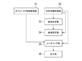
- control unit 11 of the information processing device 1 By executing the program stored in the storage unit 12, the control unit 11 according to the present embodiment functionally includes the object information acquisition unit 31 and the direction information acquisition unit 32, as illustrated in FIG. , A configuration including a reference determination unit 33, a reference setting unit 34, a rendering unit 35, and an output unit 36 is realized.
- the object information acquisition unit 31 acquires information on a virtual object to be displayed in the virtual space.
- the object information acquired by the object information acquisition unit 31 is provided from the application program side such as a game application, and includes information such as the shape and texture of one or more objects, the position and orientation of arrangement, and the like. Since the information of such an object and the process of acquiring the object are widely known, detailed description thereof is omitted here.
- the direction information acquisition unit 32 repeatedly acquires information on the line-of-sight direction of the user wearing the display device 2 at predetermined timings (for example, every 1/30 second).
- the direction information acquisition unit 31 uses information such as the posture of the display device 2 worn by the user based on a user's image taken by a camera (not shown) or output by a posture sensor included in the display device 2. It detects and acquires information on the direction of the user's head (direction of the head, direction of the front of the face).
- the direction information acquisition unit 32 may acquire information on the direction of the user's head (the direction in which the front of the face is facing) based on an image taken by a camera (not shown) provided in the display device 2.
- a widely known method such as an application of SLAM (Simultaneous Localization and Mapping) technology can be adopted.
- the direction of the user's head is expressed as follows. That is, let ⁇ be the angle of the user's face in the real space in the elevation direction (angle in the sagittal plane), ⁇ be the angle in the left-right direction (angle in the cross section), and ⁇ be the angle in the coronal plane. ..
- the direction of the user's head (direction in the world coordinate system) is represented by a set of these angles ( ⁇ , ⁇ , ⁇ ).
- the direction information acquisition unit 32 acquires the information of this set of angles as the information indicating the direction of the user's head.
- the direction information acquisition unit 32 in this example is the direction of the user's head in the real space when a predetermined initialization operation (for example, activation or calibration) is performed on the information processing device 1.
- a predetermined initialization operation for example, activation or calibration
- the amount of change in the angle from this real space reference direction to each direction, where the front direction in which the face faces) is the reference direction (called the real space reference direction) ( ⁇ , ⁇ , ⁇ ) (0, 0, 0). Detects the direction of the user's head with.
- the direction of the user's line of sight is expressed as ⁇ E for the angle from the real space reference direction to the elevation angle direction (angle in the sagittal plane) and ⁇ E for the angle in the left-right direction (angle in the cross section).
- ⁇ E for the angle from the real space reference direction to the elevation angle direction (angle in the sagittal plane)
- ⁇ E for the angle in the left-right direction (angle in the cross section).
- the direction information acquisition unit 32 is a user when the user performs a predetermined initialization operation such as starting the information processing device 1 or instructing the information processing device 1 to perform calibration.
- Information on the direction of the head is acquired.
- the direction information acquisition unit 32 sets the direction of the user's head (front direction in which the user's face faces) when the information indicating the direction of the line of sight is obtained as ( ⁇ H, ⁇ H, ⁇ H), and the information indicating the direction of the line of sight.
- ( ⁇ E, ⁇ E, ⁇ E) as ( ⁇ H + ⁇ E, ⁇ H + ⁇ E, ⁇ H).
- the direction information acquisition unit 32 may use the detected information on the direction of the user's head as it is as information on the user's line-of-sight direction.
- the information indicating the direction of the line of sight ( ⁇ E, ⁇ E, ⁇ E) is equal to the direction of the user's head (front direction in which the user's face faces) ( ⁇ H, ⁇ H, ⁇ H).
- the direction information acquisition unit 32 repeatedly acquires information indicating the direction of the user's head and information on the user's line-of-sight direction at predetermined timings (for example, once every 1/30 second) by such a method. Output.
- the reference determination unit 33 determines the reference direction (virtual space reference direction) in the user's virtual space. In the present embodiment, the reference determination unit 33 determines the virtual space reference direction of the user as follows.
- the reference determination unit 33 initially (at the time of activation, when the control unit 11 starts executing the program) acquires information on the direction of the user's head in the real space ( ⁇ H, ⁇ H, ⁇ H) acquired by the direction information acquisition unit 32. Is used to set the virtual space reference direction ( ⁇ 0, ⁇ 0, ⁇ 0).
- each component of the information representing the virtual space reference direction is an angle in the elevation angle direction (angle in a plane perpendicular to the floor surface of the virtual space) ⁇ and an angle in the left-right direction (parallel to the floor surface of the virtual space). (Angle in the plane) ⁇ and the rotation angle ⁇ around this axis with the direction of the line of sight as the rotation axis, respectively.
- the reference determination unit 33 initially acquires information on the direction of the user's head in the real space ( ⁇ H, ⁇ H, ⁇ H) or the line-of-sight direction ( ⁇ H, ⁇ H, ⁇ H) acquired by the direction information acquisition unit 32 at the time of activation.
- the reference determination unit 33 while the direction of the user's head (direction in front of the head) or the line-of-sight direction represented by the information acquired by the direction information acquisition unit 32 is a direction that satisfies a predetermined candidate determination condition.
- a candidate for the virtual space reference direction is determined based on the information on the line-of-sight direction acquired by the direction information acquisition unit 32.
- the reference determination unit 33 determines the candidate for the virtual space reference direction, but does not change the virtual space reference direction at that time.
- the information of the candidate determination flag initially set to off is used.
- the reference determination unit 33 includes the elevation direction component ⁇ H and the left-right direction component ⁇ H among the directions ( ⁇ H, ⁇ H, ⁇ H) of the user's head represented by the information acquired by the direction information acquisition unit 32, and the real space. Find the difference from the value of the corresponding component in the reference direction (0, 0, 0). Then, the reference determination unit 33 satisfies this candidate determination condition with the above candidate determination condition that the difference of the component having the largest value among the differences of each component exceeds a predetermined threshold value. Judge whether or not.
- the reference determination unit 33 determines that the candidate determination condition is satisfied.
- the reference determination unit 33 is a virtual space corresponding to the user's line-of-sight direction ( ⁇ E, ⁇ E, ⁇ E) when the user performs a predetermined candidate determination operation or action while it is determined that the candidate determination condition is satisfied. Is determined as a candidate for the virtual space reference direction.
- the predetermined candidate determination operation or action performed by the user here may be, for example, an operation of pressing a predetermined button of the operation device 3. Further, if the blinking sensor 4 is connected to the information processing device 1, the predetermined candidate determination operation or action performed by the user may be blinking. Further, the predetermined candidate determination operation or action performed by the user may be such that the line-of-sight direction is not changed for a predetermined time. Specifically, in order to detect that the user does not change the line-of-sight direction, it is detected that the maximum value of the amount of change in the line-of-sight direction of the user acquired during a predetermined time falls below a predetermined threshold value. That is, it may be detected that the person is staring at a predetermined range on the screen.
- the reference determination unit 33 determines the direction of the user's line of sight at that time.
- the reference setting unit 34 determines the direction and inclination ( ⁇ W, ⁇ W, ⁇ W, ⁇ W,) of the user's visual field in the virtual space.
- the angle of the user's face in the elevation angle direction (angle in the sagittal plane) in the virtual space is ⁇
- the angle in the left-right direction (angle in the cross section) is ⁇
- the plane in the viewing direction coronal plane.
- the angle (in the plane) is expressed as ⁇ .
- the reference setting unit 34 makes the information of the direction of the visual field stored by the reference determination unit 33 invalid, and returns the candidate determination flag to off to continue the process.
- the above setting conditions are (1) The user's line-of-sight direction or head direction is moving toward the reference direction (2) The user's line-of-sight direction or head direction is moving toward the reference direction, and blinking What has been done (3) It is determined in advance that the user has performed a predetermined setting operation or action.
- Each distance is determined by a method such as using the spherical cosine theorem.
- the reference setting unit 34 sets the setting conditions. (2) It may be assumed that the direction of the user's head is moving toward the reference direction and the user blinks. In this case, when the reference setting unit 34 determines that the direction of the user's head is moving toward the reference direction by the above method, the blink sensor 4 outputs a signal indicating that the blink sensor 4 has detected the blink. , It is assumed that the setting conditions are satisfied. When the setting condition is satisfied, the reference setting unit 34 sets the virtual space reference direction ( ⁇ 0, ⁇ 0, ⁇ 0) to the stored value ( ⁇ C, ⁇ C, ⁇ C).
- the reference setting unit 34 sets the field of view by, for example, setting the direction and inclination of the field of view by any of the above methods, and separately setting the angle of view of the field of view (for example, by following the instructions of the game application). Do.
- the rendering unit 35 renders and generates an image of an object included in the virtual three-dimensional space projected onto the user's field of view, which is set by the reference setting unit 34. Since this process is a general three-dimensional graphics process, detailed description thereof will be omitted here.
- the output unit 36 outputs an image of an object in the virtual three-dimensional space generated by the rendering unit 35 to the display device 2.
- the present embodiment basically includes the above configuration and operates as follows.
- the information processing device 1 executes a process of arranging and displaying an object in a virtual game space (virtual space) in a process of a game application or the like.
- the user's position (the position of the virtual camera for rendering) in the virtual space is shown as an example of the plan view and the side view in FIGS. 3 (a) and 3 (b), respectively.
- An example is a case where a texture of a 360-degree image is pasted on the inner surface of a spherical object P at the center.
- the information processing device 1 of the present embodiment is not limited to such an example, and can be applied to an example in which a plurality of virtual objects are arranged in a virtual three-dimensional space. ..
- the angle of the user's face in the elevation direction (angle in the sagittal plane) in the virtual three-dimensional space is ⁇
- the angle in the left-right direction (angle in the cross section) is ⁇
- the angle in the plane (in the coronal plane) of the field of view of the camera is expressed as ⁇ .
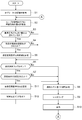
- the information processing device 1 performs the process shown in FIG. 4 to acquire information (information such as shape, position, texture, etc.) of objects arranged in the virtual space (S1).
- the information processing device 1 repeatedly acquires information on the direction of the user's head ( ⁇ H, ⁇ H, ⁇ H) and information on the line-of-sight direction ( ⁇ E, ⁇ E, ⁇ E) at predetermined timings (S2).
- the information processing apparatus 1 acquires such information, among the directions of the user's head ( ⁇ H, ⁇ H, ⁇ H), the elevation angle direction component ⁇ H and the left-right direction component ⁇ H and the reference direction (0, 0, 0) ) Is calculated from the value of the corresponding component. Then, the information processing apparatus 1 examines whether or not the difference of the component having the largest value among the obtained difference values of each component exceeds a predetermined threshold value (for example, 5 degrees) (S3). ). Here, if the difference between the above components exceeds a predetermined threshold value (S3: Yes), the information processing apparatus 1 further examines whether or not the user has performed a predetermined candidate determination operation or action (S4). ). Specifically, the predetermined candidate determination operation or action here is predetermined as an operation of pressing a predetermined button of the operation device 3.
- a predetermined threshold value for example, 5 degrees
- the information processing device 1 determines in the process S4 that the user has performed a predetermined candidate determination operation or action (S4: Yes), it corresponds to the information in the line-of-sight direction of the user ( ⁇ E, ⁇ E, ⁇ E) at that time.
- the direction of the virtual space that is, ( ⁇ E- ⁇ 0, ⁇ E- ⁇ 0, ⁇ E- ⁇ 0)
- ⁇ C, ⁇ C, ⁇ C the candidate determination flag is turned on.
- the information processing apparatus 1 determines whether or not the candidate determination flag is on (S6), and if it is on (process S6: Yes), determines whether or not the setting condition is satisfied (S7). ).
- the information processing device 1 separately determines the viewing angle of the field of view (by instructions from a game application, etc.).
- the information processing device 1 renders an image of an object in this visual field in this virtual three-dimensional space (S9), and displays the rendered image on the display device 2 (S10).
- the images presented to the left and right eyes are displayed by rendering the images of the objects in the field of view from the positions corresponding to the positions of the left and right eyes. You just have to get it.
- the information processing device 1 then returns to the process S2 to continue the process.
- the information processing apparatus 1 sets the direction of the visual field determined in the process S5 to the virtual space reference direction (S11), and sets the candidate determination flag.
- the process proceeds to process S8. That is, in this process S11, the virtual space reference direction ( ⁇ 0, ⁇ 0, ⁇ 0) of the user in the virtual three-dimensional space is set as the candidate ( ⁇ C, ⁇ C, ⁇ C) of the virtual space reference direction stored in the process S5. ..
- the in-plane angle of the field of view in this virtual space reference direction is always parallel to the floor surface, and the user's virtual space reference direction ( ⁇ 0) in the virtual three-dimensional space.
- ⁇ 0, ⁇ 0) may be set to (0, ⁇ C, 0) using only the information in the left-right direction out of the determined information in the direction of the visual field.
- the virtual space reference direction is set to ( ⁇ C, ⁇ C, 0) using the information of the elevation angle and the left-right direction. You may use some information such as, or you may set the virtual space reference direction to ( ⁇ C, ⁇ C, ⁇ C) by using all the information.
- the virtual space reference direction is then set to the direction ( ⁇ C, ⁇ C, ⁇ C) in which the user turned his / her line of sight in the past and performed a predetermined candidate determination operation or action. Therefore, after that, when the visual field is determined based on the line-of-sight direction, this virtual space reference direction is used, and the user uses the front of the head as the real space reference direction (generally, the front of the user).
- the side front side of the body
- the image in the field of view in the direction determined in the process S8 is rendered and presented.
- ⁇ the direction and inclination ( ⁇ , ⁇ , ⁇ ) of the user's visual field in the virtual space.
- process S3: No when the difference of the component having the largest value among the differences of the components in the process S3 does not exceed a predetermined threshold value (for example, 5 degrees) (process S3: No). ), And when it is not determined in the process S4 that the user has performed a predetermined candidate determination operation or action (process S4: No), the process proceeds to the process S6 and the process is continued.
- a predetermined threshold value for example, 5 degrees
- the information processing device 1 of the present embodiment of this example is connected to a display device 2 worn on the user's head and an operation device 3 operated by the user.
- the blink sensor 4 is not always necessary.
- a predetermined threshold value for example, 5 degrees
- the information processing device 1 subsequently obtains information on the user's line-of-sight direction ( ⁇ E, ⁇ E, ⁇ E) and information on the set virtual space reference direction (direction in which the character “SE” is drawn) ( ⁇ 0, Using ⁇ 0, ⁇ 0), the direction of the user's field of view in the virtual space is defined as ( ⁇ E- ⁇ 0, ⁇ E- ⁇ 0, ⁇ E- ⁇ 0), and objects within a predetermined angle of view range (field of view) in this direction.
- the image of is rendered and displayed on the display device 2.
- the user initially faces the direction in which the character "N” is drawn in the virtual space, but performs a predetermined candidate determination operation while looking at the direction in which the character "SE” is drawn.
- the virtual space is rotated around the user while the direction of the head is returned to the front side, and the direction in which the characters "SE" are drawn is the direction of the user. It is set to be in front.
- the information processing device 1 of the present embodiment of this example is connected to a display device 2 worn on the user's head, an operation device 3 operated by the user, and a blink sensor 4.
- the head is turned to the right (the direction in which ⁇ becomes larger) from the state in which the user initially faces a predetermined direction (the direction in which the character “N” is drawn). It is assumed that the direction in which the character “E” is drawn) is further directed to the right side, and the direction in which the character “SE” in FIG. 6 is drawn is directed (S31).
- a predetermined threshold value for example, 5 degrees
- the information processing device 1 receives information on the user's line-of-sight direction at that time (S32).
- the information processing device 1 subsequently obtains information on the user's line-of-sight direction ( ⁇ E, ⁇ E, ⁇ E) and information on the set virtual space reference direction (direction in which the character “SE” is drawn) ( ⁇ 0, ⁇ 0). , ⁇ 0), and the direction of the user's field of view in the virtual space is defined as ( ⁇ E- ⁇ 0, ⁇ E- ⁇ 0, ⁇ E- ⁇ 0), and the object within the range (field of view) of the predetermined angle of view in this direction.
- the image is rendered and displayed on the display device 2.
- the user initially faces the direction in which the character "N” is drawn in the virtual space, but performs a predetermined candidate determination operation while looking at the direction in which the character "SE” is drawn.
- the virtual space is rotated around the user while the blinking is performed, and the direction in which the characters "SE" are drawn is the direction of the user. It is set to be in front.
- the information processing device 1 of the present embodiment of this example is connected to a display device 2 worn on the user's head and an operation device 3 operated by the user.
- the blink sensor 4 is not always necessary.
- the predetermined button of the operation device 3 is pressed (held and held) as the candidate determination condition, and the setting condition is that the finger is released from the predetermined button of the operation device 3. And.
- the information processing device 1 moves the button.
- the information processing device 1 subsequently obtains information on the user's line-of-sight direction ( ⁇ E, ⁇ E, ⁇ E) and information on the set virtual space reference direction (direction in which the character “SE” is drawn) ( ⁇ 0, ⁇ 0). , ⁇ 0), and the direction of the user's field of view in the virtual space is defined as ( ⁇ E- ⁇ 0, ⁇ E- ⁇ 0, ⁇ E- ⁇ 0), and the object within the range (field of view) of the predetermined angle of view in this direction.
- the image is rendered and displayed on the display device 2.
- the information processing apparatus 1 is satisfied with the setting conditions at that time.
- this embodiment is not limited to this.
- the information processing device 1 uses the direction of the head in the real space at that time ( ⁇ M, ⁇ M, ⁇ M) and uses the virtual space reference direction as follows. May be set.
- an object in the direction represented by the determined virtual space reference direction is set in the direction of the visual field at that time. It will be drawn.
- the information processing device 1 is connected to the blinking sensor 4, and when the user presses a predetermined first button (a button set to instruct the rotation to the right) of the operation device 3, the information processing device 1 at that time is pressed.
- a predetermined first button a button set to instruct the rotation to the right
- a direction rotated by a predetermined angle ⁇ from the virtual space reference direction may be determined as a candidate for the virtual space reference direction.
- a predetermined second button a button set to instruct the leftward rotation of the operation device 3
- ⁇ a predetermined angle from the virtual space reference direction at that time to the left.
- the direction rotated by ⁇ (direction of ⁇ 0 ⁇ ) may be determined as a candidate for the virtual space reference direction.
- the information processing device 1 blinks the next time the user blinks after the candidate for the virtual space reference direction is set (when the blink sensor 4 outputs a signal indicating that the user blinks).
- the virtual space reference direction is set to the direction of the candidate of the determined virtual space reference direction.
- the rotation in the direction of the field of view is performed while the user is blinking.
- the direction of rotation when obtaining the candidate direction of the virtual space reference direction is not limited to the above-mentioned right direction or left direction, and may be upward or downward in the elevation angle direction depending on the setting of the button of the operation device 3. May be rotated.
- the present embodiment is not limited to this.
- the direction is determined to be rotated by a predetermined angle or more from the virtual space reference direction at that time.
- the direction rotated by the angle ⁇ of may be determined as a candidate for the virtual space reference direction.
- the virtual space reference direction may be set in the direction of the candidate of the determined virtual space reference direction.
- the operation of the operation device 3 is not required, so that the rotation in the visual field direction can be performed by a more intuitive method.
- the blink sensor 4 connected to the information processing device 1 of the present embodiment may be capable of detecting not only the blink but also the opening degree of the user's eyes. In this case, the blink sensor 4 repeatedly detects the information on the opening degree of the user's eyes at predetermined timings and outputs the information to the information processing device 1. Further, also at this time, when the user blinks, the blink sensor 4 shall output a signal indicating that the user has blinked to the information processing device 1.
- the information processing device 1 determines whether or not the opening degree of the user's eyes output by the blink sensor 4 falls below a predetermined threshold value when the candidate determination flag is on.
- the state in which the opening degree of the eyes falls below a predetermined threshold value is a so-called thin state. That is, as the threshold value here, it is assumed that a general human being is in a state where visual recognition is deteriorated.
- the setting condition for setting the virtual space reference direction is that the user has performed a predetermined setting operation, and the user's when the user performs the operation.
- the virtual space reference direction is set to ( ⁇ 0, ⁇ 0, ⁇ 0).
- ( ⁇ C + ⁇ M, ⁇ C + ⁇ M, ⁇ C + ⁇ M) may be set.
- the direction of the stored virtual space reference direction candidate is set to the direction of the user's line of sight when the above setting operation is performed. That is, the user performs a candidate determination operation or the like to determine a candidate in the virtual space reference direction while moving the head and arranging the line of sight in a desired direction, and then moves in another direction (called a setting direction). Perform the setting operation to set the virtual space reference direction with the line of sight arranged.
- the information processing apparatus 1 of this example rotates the virtual space around the position of the virtual user so that the direction represented by the candidate in the virtual space reference direction is positioned in the setting direction. This allows the user to rotate the virtual space in any direction.
- 1 Information processing device 2 Display device, 3 Operation device, 4 Blink sensor, 11 Control unit, 12 Storage unit, 13 Interface unit, 21 Video display element, 22 Optical element, 23 Line-of-sight detection unit, 31 Object information acquisition unit, 32 Direction information acquisition unit, 33 reference determination unit, 34 reference setting unit, 35 rendering unit, 36 output unit.
Landscapes
- Engineering & Computer Science (AREA)
- Theoretical Computer Science (AREA)
- Physics & Mathematics (AREA)
- General Physics & Mathematics (AREA)
- Computer Hardware Design (AREA)
- General Engineering & Computer Science (AREA)
- Computer Graphics (AREA)
- Software Systems (AREA)
- Human Computer Interaction (AREA)
- User Interface Of Digital Computer (AREA)
Abstract
仮想的な三次元空間である仮想空間内のオブジェクトに係る情報を取得し、表示装置を装着したユーザの頭部正面方向を表す情報と視線方向の情報を取得し、仮想空間の基準方向候補を決定し、所定の設定条件が満足されたときに、当該決定した基準方向候補が表す仮想空間内の方向を、仮想空間の基準方向として設定する情報処理装置である。
Description
本発明は、情報処理装置、情報処理装置の制御方法、及びプログラムに関する。
ユーザの頭部に装着され、仮想的な空間の画像をユーザに提示する表示装置を用いた情報処理システムが近年普及しつつある。このような情報処理システムでは、表示装置により表示される仮想的な空間内で、ユーザ自身が認識する体の動きと、認識上整合しない視野の移動を伴う表示を行うと、ユーザが、いわゆるVR酔いを感じることがある。
例えば、ユーザが実際には体の方向を右に向けていないのに、右側にターンしたかのような表示(仮想的な空間を相対的に、ユーザの身長方向を軸として、この軸周りに左に回転させる表示)を行うと、ユーザが認識上の違和感を感じてVR酔いの状態になることがある。
このようなVR酔いの軽減のためには、移動を不連続に行うことなどが考えられているが、不連続移動ばかりを行うのでは、現実感が損なわれ、仮想空間の体験の質が低下してしまう。
このように、近年では、体験の質の低下を抑制しつつ、VR酔いを軽減できる画像の提示を行う情報処理が求められている。
本発明は上記実情に鑑みて為されたもので、仮想空間の体験の質の低下を抑制しつつ、VR酔いを軽減できる情報処理装置、情報処理装置の制御方法、及びプログラムを提供することを、その目的の一つとする。
上記従来例の問題点を解決する本発明の一態様は、ユーザの頭部に装着される表示装置に接続される情報処理装置であって、仮想的な三次元空間である仮想空間内のオブジェクトに係る情報を取得する手段と、前記表示装置を装着したユーザの頭部正面方向を表す情報、及び当該ユーザの視線方向の情報を取得する取得手段と、前記仮想空間内に定められた仮想的な基準方向を基準としたユーザの視野を、前記取得した頭部正面方向を表す情報、または視線方向の情報に基づいて設定し、当該設定したユーザの視野内の前記オブジェクトの画像を生成して、前記表示装置に出力する画像出力手段と、前記仮想空間の基準方向候補を決定する基準決定手段と、所定の設定条件が満足されたときに、前記基準決定手段が決定した基準方向候補が表す仮想空間内の方向を、前記仮想空間の基準方向として設定する基準設定手段と、を含むこととしたものである。
本発明によると、不連続な移動を、所定の設定条件が満足されたときに行うようにしたので、仮想空間の体験の質の低下を抑制しつつ、VR酔いを軽減できる。
本発明の実施の形態について図面を参照しながら説明する。本発明の実施の形態に係る情報処理装置1は、表示装置2が表示すべき画像を表す画像データを供給する装置であって、例えば家庭用ゲーム機、携帯型ゲーム機、パーソナルコンピューター、スマートフォン、タブレット等である。具体的にこの情報処理装置1は、図1に示すように、ユーザの頭部に装着される表示装置2や操作デバイス3等に接続され、制御部11と、記憶部12と、インタフェース部13と、を含んで構成される。
ここで制御部11は、CPU等のプログラム制御デバイスであり、記憶部12に格納されているプログラムを実行する。本実施の形態では、この制御部11は、仮想的な三次元空間内のオブジェクトに係る情報を、例えばゲームのアプリケーション等から取得して、この情報に基づいて上記仮想的な三次元空間(仮想空間)の画像を描画して、表示装置2に出力する処理を実行する。この描画の際、制御部11は、指定された三次元空間中の視点から、別途定めた視野内の画像をレンダリングする処理を実行する。このレンダリングの処理は広く知られたものであるので、ここでの詳細な説明を省略する。
制御部11は、表示装置2を装着したユーザの頭部正面方向を表す情報、及び当該ユーザの視線方向の情報を取得する。制御部11は、仮想空間内に定めた仮想的な基準方向(以下、仮想空間基準方向と呼ぶ)を基準としたユーザの視野を、当該取得した頭部正面方向を表す情報、または視線方向の情報に基づいて設定する。そして制御部11は、当該設定したユーザの視野内のオブジェクトの画像を生成して、表示装置2に出力する。
また制御部11は、例えば取得した情報が表すユーザの頭部正面方向または視線方向が、所定の候補決定条件を満足する方向である間に、当該取得した視線方向の情報に基づいて、仮想空間内の基準方向の候補(仮想空間基準方向候補)を決定する。
さらに制御部11は、仮想空間基準方向候補が決定された後、上記候補決定条件とは異なる所定の設定条件が満足されたときに、当該決定した仮想空間基準方向候補が表す仮想空間内の方向を、仮想空間基準方向として設定する。
ここで、設定条件は、ユーザの視覚認知能力が低下しているとの条件であり、例えば頭部を回転しているとき、つまり視野が変化しているときや、まばたきをしたとき、目を細く開けた状態としているとき、例えば薄目にしているときなどが広く知られている。
本実施の形態では、一例として上記仮想空間基準方向が仮想空間におけるユーザの前方に一致するものとするとき、制御部11は、候補決定条件を満足している間に取得した方向を基準方向の候補としておく。ここでユーザの前方は、ユーザが頭部をまっすぐ前に向けたときの当該頭部の方向を意味する。そしてその後、制御部11は、まばたきをしたときなど、所定の設定条件が満足されたときに、当該基準方向の候補とした方向がユーザの前方の方向となるように設定する。この制御部11の詳しい動作については、後に述べる。
記憶部12は、RAM等のメモリデバイスを少なくとも一つ含み、制御部11が実行するプログラムを格納する。また、この記憶部12は制御部11のワークメモリとしても動作し、制御部11がプログラム実行の過程で使用するデータを格納する。このプログラムは、コンピュータ可読かつ非一時的な記録媒体に格納されて提供され、この記憶部12に格納されたものであってもよい。
インタフェース部13は、操作デバイス3や表示装置2との間で情報処理装置1の制御部11がデータ通信を行うためのインタフェースである。情報処理装置1は、このインタフェース部13を介して有線又は無線のいずれかで操作デバイス3や表示装置2等と接続される。一例として、このインタフェース部13は、情報処理装置1が供給する画像データや音声を表示装置2に送信するために、HDMI(登録商標)(High-Definition Multimedia Interface)などのマルチメディアインタフェースを含んでよい。また、このインタフェース部13は、表示装置2から各種の情報を受信したり、制御信号等を送信したりするために、USB等のデータ通信インタフェースを含んでよい。さらにインタフェース部13は、操作デバイス3に対するユーザの操作入力の内容を示す信号を受信するために、USB等のデータ通信インタフェースを含んでよい。
表示装置2は、ユーザが頭部に装着して使用する表示デバイスであって、情報処理装置1から供給される画像データや音声のデータを受け付ける。そしてこの表示装置2は、入力された画像データを、表示装置2の映像表示素子21における表示部の画素の配列に並べ替えた画像データを生成する。この映像表示素子21については後に述べる。また表示装置2は、さらに、必要に応じて、供給された画像データが表す画像に対して、表示装置2の光学系によって生じる歪みを補正する処理などを実行し、補正された画像を表す映像信号を生成する。
なお、ここで生成する映像信号は、左目用のものと右目用のものとの二つの映像信号を含んでいてよい。また表示装置2は、生成した映像信号に応じた映像を表示し、ユーザに閲覧させる。本実施形態では、表示装置2はユーザの右目と左目とのそれぞれの目の前に、それぞれの目に対応した映像を表示するものとする。この表示装置2は、図1に示したように、映像表示素子21、及び光学素子22を含んで構成される。またこの表示装置2は、視線検出部23を備えてもよい。
映像表示素子21は、例えば、複数の画素を二次元的に配列した有機EL表示パネルや液晶表示パネルなどであって、情報処理装置1から入力される指示に従って映像を表示する。この映像表示素子21は、左目用の映像と右目用の映像とを一列に並べて表示する1つの表示素子であってもよいし、左目用の映像と右目用の映像とをそれぞれ独立に表示する一対の表示素子を含んで構成されてもよい。また、本実施の形態の別の例では、スマートフォンの画面をそのまま映像表示素子21として用いてもよいし、ユーザの網膜に直接映像を投影する網膜照射型(網膜投影型)の装置であってもよい。
映像表示素子21をスマートフォンの画面とする場合、このスマートフォンが情報処理装置1から供給される画像データや音声のデータを受け付ける。そしてこの表示装置2は、入力された画像データを、表示装置2の映像表示素子21における表示部の画素の配列に並べ替えた画像データを生成する。また表示装置2は、さらに必要に応じて、供給された画像データが表す画像に対して、表示装置2の光学系によって生じる歪みを補正する処理などを実行し、補正された画像を表す映像信号を生成することとなる。また、映像表示素子21はユーザの網膜に直接、映像を投影するデバイスであってもよい。
光学素子22は、レンズや、ホログラム、プリズム、ハーフミラーなどであって、ユーザの目の前に配置され、映像表示素子21が表示する映像の光を透過又は屈折させて、ユーザの目に入射させる。具体的に、この光学素子22は、左目用光学素子22Lと、右目用光学素子22Rとを含み、映像表示素子21が表示する左目用の映像は、左目用光学素子22Lを経由してユーザの左目に入射し、右目用の映像は右目用光学素子22Rを経由してユーザの右目に入射するようにしてもよい。これによりユーザは、表示装置2を頭部に装着した状態で、左目用の映像を左目で、右目用の映像を右目で、それぞれ見ることができるようになる。なお、本実施形態において表示装置2は、ユーザが外界の様子を視認することができない非透過型の表示装置であるものとしている。もっとも、本発明の実施の形態の別の例では表示装置2は非透過型に限られず、ユーザが外界を視認可能な(外界の像に表示された像がオーバーレイされる)、透過型の表示装置であってもよい。この場合、予めユーザ周囲の仮想的な三次元空間に配されたメニューの画像などを表示(外界の像にオーバーレイして表示)する際に、以下に説明する本実施の形態の処理を利用できる。
表示装置2が視線検出部23を備える例では、この視線検出部23は、表示装置2を装着した状態でユーザの左右の目の少なくとも一方の瞳の位置を検出する。具体的な例として、この視線検出部23は、カメラを含んで構成され、ユーザの目を撮像する。そして視線検出部23は、当該撮像したユーザの目のうち、瞳を検出して、目の範囲のどの位置に瞳が位置するかを表す情報を得る。そして視線検出部23は、頭部の方向(瞳が目の中心にあるときの視線の方向)に対して、ユーザの視線がどの方向を向いているかを表す情報を、当該瞳の位置の情報に基づいて演算して出力する。このような視線検出部23は、アイ・トラッカーなどとして広く知られたものを採用できるので、ここでの詳しい動作の説明は省略する。
また操作デバイス3は、例えば家庭用ゲーム機のコントローラ等であって、ユーザが情報処理装置1に対して各種の指示操作を行うために使用される。操作デバイス3に対するユーザの操作入力の内容は、有線又は無線のいずれかにより情報処理装置1に送信される。なお、操作デバイス3は必ずしも情報処理装置1と別体でなくてもよく、情報処理装置1の筐体表面に配置された操作ボタンやタッチパネル等を含んでもよい。
また本実施の形態の情報処理装置1は、ユーザのまばたきを検出するまばたきセンサ4に接続されてもよい。このまばたきセンサ4は例えば、表示装置2と一体に構成され、表示装置2を装着したユーザの目の近傍の筋電位を計測してまばたきを検出するものであってもよい。または、このまばたきセンサ4は、表示装置2と一体に構成され、表示装置2を装着したユーザのまぶたの動きをドップラーセンサで検出するものであってもよい。さらにまばたきセンサ4は、視線トラッカーを用いてもよい。この場合、視線トラッカーが視線を検出できなかった(角膜反射の検出ができないなどの理由で、視線が検出できなかった)ときに、ユーザがまぶたを閉じたと判断する。また視線トラッカーをまばたきセンサ4として用いて、瞳の認識を行い、瞳が認識できないときに、ユーザがまぶたを閉じた判断することとしてもよいし、瞳の認識に代えて、目の開口度を推定してまぶたを閉じたか否かを判断することとしてもよい。
まばたきセンサ4は、ユーザがまぶたを閉じたときに、まばたきがあったものとしてまばたきを検出した旨の信号を出力する。
次に、情報処理装置1の制御部11の動作について説明する。本実施の形態に係る制御部11は、記憶部12に格納されたプログラムを実行することにより、機能的に、図2に例示するように、オブジェクト情報取得部31と、方向情報取得部32と、基準決定部33と、基準設定部34と、レンダリング部35と、出力部36とを含む構成を実現する。
オブジェクト情報取得部31は、仮想空間内に表示する仮想的なオブジェクトの情報を取得する。具体的にこのオブジェクト情報取得部31が取得するオブジェクトの情報は、ゲームアプリケーション等のアプリケーションプログラム側から提供され、一つ以上のオブジェクトの形状やテクスチャ、配置する位置や向き等の情報を含む。このようなオブジェクトの情報やその取得の処理については広く知られているので、ここでの詳しい説明は省略する。
方向情報取得部32は、表示装置2を装着したユーザの視線方向の情報を、所定のタイミングごと(例えば1/30秒ごとのなど定期的)に繰り返し取得する。一例として、この方向情報取得部31は、ユーザが装着する表示装置2の姿勢を図示しないカメラで撮影したユーザの画像に基づいて、あるいは表示装置2が備える姿勢センサが出力する情報等を用いて検出して、ユーザの頭部の方向(頭部の向き、顔の正面の向いている方向)の情報を取得する。
またこの方向情報取得部32は、表示装置2が備える、図示しないカメラが撮影した画像に基づいてユーザの頭部の方向(顔の正面の向いている方向)の情報を取得してもよい。このような処理は例えばSLAM(Simultaneous Localization and Mapping)技術を応用したものなど、広く知られた方法を採用できる。
また以下の説明では、ユーザの頭部の方向を次のように表すものとする。すなわち、実空間でのユーザの顔の仰角方向への角度(矢状面内の角度)をθ、左右方向への角度(横断面内の角度)をφ、冠状面内の角度をψとする。そしてユーザの頭部の方向(ワールド座標系での方向)は、これらの角度のセット(θ,φ,ψ)で表されるものとする。方向情報取得部32は、この角度のセットの情報を、ユーザの頭部の方向を表す情報として取得するものとする。
なお、この例の方向情報取得部32は、情報処理装置1に対して所定の初期化操作(例えば起動、あるいはキャリブレーション)を行ったときの実空間でのユーザの頭部の方向(ユーザの顔が向く正面方向)を基準の方向(実空間基準方向と呼ぶ)(θ,φ,ψ)=(0,0,0)として、この実空間基準方向からの各方向への角度の変化量でユーザの頭部の方向を検出する。
また、方向情報取得部32は、ユーザの視線方向の情報を取得する。具体的に方向情報取得部32は、表示装置2が視線検出部23を備える場合は、表示装置2からユーザの視線の方向を表す情報(ユーザの頭部の方向を基準とした方向)の情報を得る。この情報もまた、視線の方向を表す情報を得たときの、実空間でのユーザの頭部の方向(ユーザの顔が向く正面方向)を実空間基準方向(θ′H,φ′H,ψ′H)=(0,0,0)として表す。すなわちユーザの視線の方向は、この実空間基準方向から仰角方向への角度(矢状面内の角度)をΔθE、左右方向への角度(横断面内の角度)をΔφEとして表されるものとする。なお、瞳は冠状面内で回転しても視線方向には変化がないので、冠状面内の成分は無視する。
つまり本実施の形態のこの例では、方向情報取得部32は、ユーザが情報処理装置1を起動、あるいは情報処理装置1にキャリブレーションの指示を行うなど所定の初期化操作を行ったときのユーザの頭部の方向(ユーザの顔が向く正面方向)の情報を取得しておく。以下、方向情報取得部32は、ここで取得したユーザの頭部の方向を、実空間基準方向(θ,φ,ψ)=(0,0,0)とする。そして方向情報取得部32は、視線の方向を表す情報を得たときのユーザの頭部の方向(ユーザの顔が向く正面方向)を(θH,φH,ψH)として、視線の方向を表す情報(θE,φE,ψE)を、(θH+ΔθE,φH+ΔφE,ψH)と、求める。
また方向情報取得部32は、表示装置2が視線検出部23を備えない場合は、検出したユーザの頭部の方向の情報をそのまま、ユーザの視線方向の情報としてもよい。この場合は、視線の方向を表す情報(θE,φE,ψE)は、ユーザの頭部の方向(ユーザの顔が向く正面方向)(θH,φH,ψH)と等しいものとなる。
方向情報取得部32は、このような方法でユーザの頭部の方向を表す情報と、ユーザの視線方向の情報とを所定のタイミングごと(例えば1/30秒に一度など)に繰り返し取得して出力する。
基準決定部33は、ユーザの仮想空間内での基準方向(仮想空間基準方向)を決定する。本実施の形態では基準決定部33は、次のようにしてユーザの仮想空間基準方向を決定する。
基準決定部33は、当初(起動時、制御部11によるプログラムの実行開始時)は方向情報取得部32が取得した、現実空間でのユーザの頭部の方向の情報(θH,φH,ψH)を用いて、仮想空間基準方向(α0,β0,γ0)を設定する。
ここで、仮想空間基準方向を表す情報の各成分は、仰角方向への角度(仮想空間の床面に垂直な面内での角度)α、左右方向への角度(仮想空間の床面に平行な面内での角度)β、及び視線の方向を回転軸とした、この軸周りでの回転角度γをそれぞれ表すものである。
本実施の形態では、基準決定部33は、当初は、起動時に方向情報取得部32が取得した、現実空間でのユーザの頭部の方向の情報(θH,φH,ψH)、または視線方向(θE,φE,ψE)を用い、仮想空間基準方向(α0,β0,γ0)を、(α0,β0,γ0)=(θH,φH,ψH)または(α0,β0,γ0)=(θE,φE,ψE)と定める。
またこの基準決定部33は、方向情報取得部32が取得した情報が表すユーザの頭部の方向(頭部の正面の方向)または視線方向が、所定の候補決定条件を満足する方向である間に、方向情報取得部32が取得した視線方向の情報に基づいて、仮想空間基準方向の候補を決定する。本実施の形態では、基準決定部33は、仮想空間基準方向の候補を決定するが、その時点では仮想空間基準方向を変更しない。以下の説明では、基準決定部33が仮想空間基準方向の候補を決定した状態にあるか否かを表すため、当初はオフに設定される候補決定フラグの情報を用いる。
具体的に、基準決定部33は、方向情報取得部32が取得した情報が表すユーザの頭部の方向(θH,φH,ψH)のうち、仰角方向成分θH及び左右方向成分φHと、実空間基準方向(0,0,0)の対応する成分の値との差を求める。そして基準決定部33は、各成分の差の値のうち最も大きい値となっている成分の差が予め定めたしきい値を超えることを、上記候補決定条件として、この候補決定条件が満足されるか否かを判断する。
例えば、しきい値を5度とする場合に、ユーザが仰角方向にはほとんど首を動かすことなく(θH=0)、右方向に90度だけ首を向けた(φH=90度)とするとき、基準方向の対応する成分の差は、それぞれΔθH=0,ΔφH=90となる。そこで、基準決定部33は、これらの値のうち最も大きい値であるΔφH=90が、しきい値である5度を超えるか否かを判断する。ここでは当該値がしきい値を超えているので、基準決定部33は、候補決定条件が満足されたと判断する。
基準決定部33は、この候補決定条件が満足されたと判断されている間に、ユーザが所定の候補決定操作または行動をしたときのユーザの視線方向(θE,φE,ψE)に相当する仮想空間の方向を仮想空間基準方向の候補として決定する。
ここでユーザが行う所定の候補決定操作または行動は、例えば操作デバイス3の所定のボタンを押下する操作であってもよい。また、情報処理装置1にまばたきセンサ4が接続されているならば、ユーザが行う所定の候補決定操作または行動は、まばたきであってもよい。さらにユーザが行う所定の候補決定操作または行動は、所定の時間の間、視線方向を変化させないというものであってもよい。具体的にユーザが視線方向が変化させないことを検出するには、所定の時間の間に取得されたユーザの視線の方向の変化量の最大値が所定のしきい値を下回ったことを検出すること、つまり画面上の所定の範囲を凝視していることを検出することとすればよい。
基準決定部33は、例えばユーザが右方向に5度以上、一例として90度頭部を回転させた状態で、操作デバイス3の所定のボタンを押下したとき、その時点でのユーザの視線方向の情報(θE,φE,ψE)に相当する仮想空間の方向を、仮想空間基準方向の候補として決定して記憶し、候補決定フラグをオンとする。つまり、基準決定部33は、ユーザが操作デバイス3の所定のボタンを押下した時点での仮想空間基準方向を表す値をα0,β0,γ0として、仮想空間基準方向の候補を、(αC,βC,γC)=(θE-α0,φE-β0,ψE-γ0)と決定して記憶する。
基準設定部34は、候補決定フラグがオンでない場合(基準決定部33が仮想空間基準方向の候補を決定した状態でないとき)は、仮想空間内のユーザの視野の方向及び傾き(αW,βW,γW)をαW=θE-α0,βW=φE-β0,γW=ψE-γ0と設定し、視野の画角を予め定めた値とする。なお、ここでは仮想空間内でのユーザの顔の仰角方向への角度(矢状面内の角度)をα、左右方向への角度(横断面内の角度)をβ、視野方向の面(冠状面内)の角度をγとして表現している。
またこの基準設定部34は、候補決定フラグがオンであるとき(基準決定部33が仮想空間基準方向の候補を決定したとき)には、候補決定条件とは別に定められた、所定の設定条件が満足されたか否かを判断する。そしてこの設定条件が満足されていないときには、基準決定部33が仮想空間基準方向の候補を決定していない間と同様、仮想空間内のユーザの視野の方向及び傾き(α,β,γ)をα=θE-α0,β=φE-β0,γ=ψE-γ0と設定し、視野の画角を予め定めた値とする。つまり、この段階では仮想空間におけるユーザの前方に相当する仮想空間の方向は、決定した仮想空間基準方向の候補の方向へと変化していない。
一方、候補決定フラグがオンであるときに上記設定条件が満足されたと判断すると、基準設定部34は、新たな仮想空間基準方向(α0,β0,γ0)を、上記記憶している仮想空間基準方向の候補(αC,βC,γC)に設定する。また基準設定部34は、ユーザの視野の方向及び傾き(α,β,γ)を、ユーザの視線方向の情報(θE,φE,ψE)と、新たに設定した仮想空間基準方向(α0,β0,γ0)とを用いて、(α,β,γ)=(θE-α0,φE-β0,ψE-γ0)と設定する。
そして基準設定部34は、基準決定部33が記憶した視野の方向の情報を削除するなどして無効なものとし、候補決定フラグをオフに戻して処理を続ける。
ここで、上記設定条件は、
(1)ユーザの視線方向または頭部の方向が基準方向に向かって移動していること
(2)ユーザの視線方向または頭部の方向が基準方向に向かって移動しており、かつ、まばたきが行われたこと
(3)ユーザが所定の設定操作または行動を行ったこと
などとして予め定める。
(1)ユーザの視線方向または頭部の方向が基準方向に向かって移動していること
(2)ユーザの視線方向または頭部の方向が基準方向に向かって移動しており、かつ、まばたきが行われたこと
(3)ユーザが所定の設定操作または行動を行ったこと
などとして予め定める。
このために基準設定部34は、方向情報取得部32が所定のタイミングごとに繰り返し出力するユーザの視線方向の情報Ei(i=1,2,…)または頭部の方向を表す情報Hi(i=1,2,…)を参照し、ある時点の情報(例えば最後に出力された情報Hn)と基準方向との距離Dn、及びその一つ前の時点(例えばHn-1)と基準方向との距離Dn-1とを求めてもよい。
なお、ここで基準設定部34は、設定条件を満足するか否かを判断する際には、方向情報取得部32が出力する情報のうち、冠状面内の角度は無視する。例えばHn=(θHn,φHn),Hn-1=(θHn-1,φHn-1)として、これらと基準方向との距離を求める。各距離は、球面余弦定理を用いる等の方法により、
D=cos-1(sin θ・sin 0+cosθ・cos0・cos(φ-0))
=cos-1(cosθ・cosφ)
と求めることができる。例えば、頭部の方向を表す情報を用いる場合、基準設定部34は、
Dn=cos-1(cosθHn・cosφHn)、
Dn-1=cos-1(cosθHn-1・cosφHn-1)
を求め、Dn<Dn-1であれば、ユーザの頭部の方向が基準方向に向かって移動していると判断する。
D=cos-1(sin θ・sin 0+cosθ・cos0・cos(φ-0))
=cos-1(cosθ・cosφ)
と求めることができる。例えば、頭部の方向を表す情報を用いる場合、基準設定部34は、
Dn=cos-1(cosθHn・cosφHn)、
Dn-1=cos-1(cosθHn-1・cosφHn-1)
を求め、Dn<Dn-1であれば、ユーザの頭部の方向が基準方向に向かって移動していると判断する。
具体的に基準設定部34が、設定条件を、
(1)ユーザの頭部の方向が基準方向に向かって移動していること
とする場合について説明する。この場合、基準設定部34は、上記の方法により、ユーザの頭部の方向が基準方向に向かって移動していると判断すると、仮想空間基準方向(α0,β0,γ0)を、記憶している値(αC,βC,γC)に設定する。そして基準設定部34は、その後、ユーザの視野の方向及び傾き(α,β,γ)を、ユーザの視線方向の情報(θE,φE,ψE)と、新たに設定した仮想空間基準方向(α0,β0,γ0)とを用いて、(α,β,γ)=(θE-α0,φE-β0,ψE-γ0)と設定する。
(1)ユーザの頭部の方向が基準方向に向かって移動していること
とする場合について説明する。この場合、基準設定部34は、上記の方法により、ユーザの頭部の方向が基準方向に向かって移動していると判断すると、仮想空間基準方向(α0,β0,γ0)を、記憶している値(αC,βC,γC)に設定する。そして基準設定部34は、その後、ユーザの視野の方向及び傾き(α,β,γ)を、ユーザの視線方向の情報(θE,φE,ψE)と、新たに設定した仮想空間基準方向(α0,β0,γ0)とを用いて、(α,β,γ)=(θE-α0,φE-β0,ψE-γ0)と設定する。
なお、頭部の方向に代えて視線方向の情報を用いる場合は、基準設定部34は、
Dn=cos-1(cosθEn・cosφEn)、
Dn-1=cos-1(cosθEn-1・cosφEn-1)
を求め、Dn<Dn-1であれば、ユーザの頭部の方向が基準方向に向かって移動していると判断することとすればよい。
Dn=cos-1(cosθEn・cosφEn)、
Dn-1=cos-1(cosθEn-1・cosφEn-1)
を求め、Dn<Dn-1であれば、ユーザの頭部の方向が基準方向に向かって移動していると判断することとすればよい。
また情報処理装置1にまばたきセンサ4が接続されている場合は、基準設定部34は、設定条件を、
(2)ユーザの頭部の方向が基準方向に向かって移動しており、かつ、まばたきが行われたこと
としてもよい。この場合、基準設定部34は、上記の方法により、ユーザの頭部の方向が基準方向に向かって移動していると判断したときに、まばたきセンサ4がまばたきを検出した旨の信号を出力すると、設定条件が満足されたものとする。基準設定部34は、設定条件が満足されたものとしたときには、仮想空間基準方向(α0,β0,γ0)を、記憶している値(αC,βC,γC)に設定する。そして基準設定部34は、その後、ユーザの視野の方向及び傾き(α,β,γ)を、ユーザの視線方向の情報(θE,φE,ψE)と、新たに設定した仮想空間基準方向(α0,β0,γ0)とを用いて、(α,β,γ)=(θE-α0,φE-β0,ψE-γ0)と設定する。なお、頭部の方向に代えて視線方向の情報を用いる場合の動作は上述の例と同様であるので、繰り返しての説明は省略する。
(2)ユーザの頭部の方向が基準方向に向かって移動しており、かつ、まばたきが行われたこと
としてもよい。この場合、基準設定部34は、上記の方法により、ユーザの頭部の方向が基準方向に向かって移動していると判断したときに、まばたきセンサ4がまばたきを検出した旨の信号を出力すると、設定条件が満足されたものとする。基準設定部34は、設定条件が満足されたものとしたときには、仮想空間基準方向(α0,β0,γ0)を、記憶している値(αC,βC,γC)に設定する。そして基準設定部34は、その後、ユーザの視野の方向及び傾き(α,β,γ)を、ユーザの視線方向の情報(θE,φE,ψE)と、新たに設定した仮想空間基準方向(α0,β0,γ0)とを用いて、(α,β,γ)=(θE-α0,φE-β0,ψE-γ0)と設定する。なお、頭部の方向に代えて視線方向の情報を用いる場合の動作は上述の例と同様であるので、繰り返しての説明は省略する。
さらに基準設定部34は、設定条件を、
(3)ユーザが所定の設定操作または行動を行ったこと
としてもよい。この場合、基準設定部34は、ユーザが操作デバイス3の所定のボタンを押下(または押下した状態から放す)する操作を行ったか、あるいは、まばたきなどの行動を行った、など、所定の設定操作や行動を行った場合に、設定条件が満足されたとして、仮想空間基準方向(α0,β0,γ0)を、記憶している値(αC,βC,γC)に設定する。そして基準設定部34は、その後、ユーザの視野の方向及び傾き(α,β,γ)を、ユーザの視線方向の情報(θE,φE,ψE)と、新たに設定した仮想空間基準方向(α0,β0,γ0)とを用いて、(α,β,γ)=(θE-α0,φE-β0,ψE-γ0)と設定する。
(3)ユーザが所定の設定操作または行動を行ったこと
としてもよい。この場合、基準設定部34は、ユーザが操作デバイス3の所定のボタンを押下(または押下した状態から放す)する操作を行ったか、あるいは、まばたきなどの行動を行った、など、所定の設定操作や行動を行った場合に、設定条件が満足されたとして、仮想空間基準方向(α0,β0,γ0)を、記憶している値(αC,βC,γC)に設定する。そして基準設定部34は、その後、ユーザの視野の方向及び傾き(α,β,γ)を、ユーザの視線方向の情報(θE,φE,ψE)と、新たに設定した仮想空間基準方向(α0,β0,γ0)とを用いて、(α,β,γ)=(θE-α0,φE-β0,ψE-γ0)と設定する。
基準設定部34は、例えば上記のいずれかの方法で視野の方向及び傾きを設定し、視野の画角については別途(例えばゲームアプリケーションの指示に従うなどして)設定することで、視野の設定を行う。
レンダリング部35は、基準設定部34が設定した、ユーザの視野に投影した仮想的な三次元空間に含まれるオブジェクトの画像をレンダリングして生成する。この処理は、一般的な三次元グラフィックスの処理であるので、ここでの詳しい説明を省略する。出力部36は、レンダリング部35が生成した、仮想的な三次元空間内のオブジェクトの画像を、表示装置2に対して出力する。
[動作]
本実施の形態は、以上の構成を基本的に備えてなり、次のように動作する。以下の説明では、情報処理装置1は、ゲームアプリケーション等の処理において、仮想的なゲーム空間(仮想空間)内にオブジェクトを配して表示する処理を実行しているものとする。なお、以下では、説明のため、図3(a),(b)にそれぞれ平面図及び側面図を例示するように、仮想空間でのユーザの位置(レンダリング用の仮想的なカメラの位置)を中心とした球面状のオブジェクトPの内面に、360度画像のテクスチャを貼り付けた場合を例とする。もっとも、本実施の形態の情報処理装置1はこのような例に限られるものではなく、仮想的な三次元空間内に、複数の仮想的なオブジェクトが配されているような例にも適用できる。
本実施の形態は、以上の構成を基本的に備えてなり、次のように動作する。以下の説明では、情報処理装置1は、ゲームアプリケーション等の処理において、仮想的なゲーム空間(仮想空間)内にオブジェクトを配して表示する処理を実行しているものとする。なお、以下では、説明のため、図3(a),(b)にそれぞれ平面図及び側面図を例示するように、仮想空間でのユーザの位置(レンダリング用の仮想的なカメラの位置)を中心とした球面状のオブジェクトPの内面に、360度画像のテクスチャを貼り付けた場合を例とする。もっとも、本実施の形態の情報処理装置1はこのような例に限られるものではなく、仮想的な三次元空間内に、複数の仮想的なオブジェクトが配されているような例にも適用できる。
情報処理装置1は、ユーザが表示装置2を装着して電源を投入した当初のユーザの頭部の方向を表す情報を取得し、当該取得した情報が(θ,φ,ψ)=(0,0,0)の方向(実空間基準方向)であるものとして初期化するものとする。なお、ここでは既に述べたように、ユーザの顔の仰角方向への角度(矢状面内の角度)をθ、左右方向への角度(横断面内の角度)をφ、冠状面内の角度をψとしている。
また情報処理装置1は、この時点での現実空間でのユーザの頭部の方向の情報(θ,φ,ψ)=(0,0,0)を用いて、仮想的な三次元空間内でのユーザの視線の基準方向(仮想空間基準方向)を、(α0,β0,γ0)=(θ,φ,ψ)=(0,0,0)と設定する。ここでも仮想的な三次元空間内でのユーザの顔の仰角方向への角度(矢状面内の角度)をα、左右方向への角度(横断面内の角度)をβ、視野(仮想的なカメラの視野)の面内(冠状面内)の角度をγとして表現している。
そして情報処理装置1は、図4に示す処理を行い、仮想空間内に配されるオブジェクトの情報(形状や、位置、テクスチャなどの情報)を取得する(S1)。以下、情報処理装置1は、所定のタイミングごとにユーザの頭部の方向の情報(θH,φH,ψH)と、視線方向の情報(θE,φE,ψE)とを繰り返し取得する(S2)。
また情報処理装置1は、これらの情報を取得すると、そのうちユーザの頭部の方向(θH,φH,ψH)のうち、仰角方向成分θH及び左右方向成分φHと、基準方向(0,0,0)の対応する成分の値との差を求める。そして情報処理装置1は、当該求めた各成分の差の値のうち最も大きい値となっている成分の差が予め定めたしきい値(例えば5度)を超えているか否かを調べる(S3)。ここで、上記成分の差が予め定めたしきい値を超えていれば(S3:Yes)、情報処理装置1はさらに、ユーザが所定の候補決定操作または行動をしたか否かを調べる(S4)。具体的に、ここでの所定の候補決定操作または行動は、操作デバイス3の所定のボタンを押下する操作などとして予め定めておく。
情報処理装置1は、処理S4において、ユーザが所定の候補決定操作または行動をしたと判断すると(S4:Yes)、その時点でのユーザの視線方向の情報(θE,φE,ψE)に相当する仮想空間の方向(つまり、(θE-α0,φE-β0,ψE-γ0))を、仮想空間基準方向の候補(αC,βC,γC)として決定して記憶し、候補決定フラグをオンとする(S5)。
次に、情報処理装置1は、候補決定フラグがオンであるか否かを判断し(S6)、オンであれば(処理S6:Yes)、設定条件が満足されたか否かを判断する(S7)。
ここで設定条件が満足されていないとき(S7:No)は、仮想的な三次元空間内のユーザの視野の方向及び傾き(α,β,γ)をα=θE-α0,β=φE-β0,γ=ψE-γ0と設定する(S8:視線方向に基づく視野決定)。なお、情報処理装置1は、視野の画角については別途(ゲームアプリケーションの指示によるなどして)定める。
そして情報処理装置1は、この仮想的な三次元空間内の、この視野内のオブジェクトの画像をレンダリングして(S9)、当該レンダリングして得た画像を表示装置2に表示させる(S10)。なお、ここで左右の目で互いに異なる画像を表示する場合には、左右の目の位置に対応する位置から上記視野内のオブジェクトの画像をレンダリングすることで、左右の目にそれぞれ提示する画像を得ることとすればよい。情報処理装置1は、そして、処理S2に戻って処理を続ける。
また処理S7において、設定条件が満足されていたときには(S7:Yes)、情報処理装置1は、処理S5で決定された視野の方向を仮想空間基準方向に設定し(S11)、候補決定フラグをオフとして(S12)、処理S8に移行する。つまり、この処理S11では仮想的な三次元空間内のユーザの仮想空間基準方向(α0,β0,γ0)が処理S5で記憶した仮想空間基準方向の候補(αC,βC,γC)に設定される。なお、仮想空間基準方向を定める際には、この仮想空間基準方向の視野の面内の角度は常に床面に平行なものとして、仮想的な三次元空間内のユーザの仮想空間基準方向(α0,β0,γ0)を決定された視野の方向の情報のうち、左右方向の情報のみを用いて(0,βC,0)に設定してもよい。また、仮想空間が宇宙空間である場合など、天地が反転しても構わない場合などでは、仰角と左右方向との情報を用いてこの仮想空間基準方向を(αC,βC,0)に設定するなど、一部の情報を用いることとしても構わないし、すべての情報を用いて仮想空間基準方向を(αC,βC,γC)に設定してもよい。
これにより、設定条件が満足されると、その後、仮想空間基準方向がユーザが過去に視線を向けて所定の候補決定操作や行動を行った方向(αC,βC,γC)に設定される。従って、これ以後は、視線方向に基づいて視野を決定する際に、この仮想空間基準方向が利用されることとなり、ユーザが頭部の正面を、実空間基準方向(一般的にはユーザの正面側(体の前方側))を向けたときに、処理S8で決定した方向の視野内の画像がレンダリングされて提示されるようになる。
また情報処理装置1は、処理S6において、候補決定フラグがオフであったとき(処理S6:No)には、仮想空間内のユーザの視野の方向及び傾き(α,β,γ)をα=θE-α0,β=φE-β0,γ=ψE-γ0と設定し(S8:視線方向に基づく視野決定)、処理S9に移行して処理を続ける。
さらに情報処理装置1は、処理S3において各成分の差の値のうち最も大きい値となっている成分の差が予め定めたしきい値(例えば5度)を超えていないとき(処理S3:No)、及び、処理S4においてユーザが所定の候補決定操作または行動をしたと判断しなかったとき(処理S4:No)には、処理S6に移行して処理を続ける。
以下、さらに設定条件の内容に応じた動作例について、それぞれ分けて説明する。
[第1の動作例]
まず設定条件を、ユーザの視線方向または頭部の方向が基準方向に向かって移動していることを条件とする場合について説明する。
まず設定条件を、ユーザの視線方向または頭部の方向が基準方向に向かって移動していることを条件とする場合について説明する。
この例の本実施の形態の情報処理装置1は、ユーザの頭部に装着される表示装置2、及びユーザにより操作される操作デバイス3に接続される。この例では、まばたきセンサ4は必ずしも必要ではない。
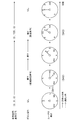
図5に例示するように、当初、ユーザが所定の方向(「N」の文字が描画されている向き)を向いている状態から、頭部を右(φが大きくなる方向、図5の「E」の文字が描画されている向き)に向け、さらに視線をより右側に向けて、図5のSEの向きを見る方向へ向けたとする(S21)。このとき、情報処理装置1がユーザの頭部の方向、及び視線方向の情報を取得して、頭部の方向(θH,φH,ψH)=(0,90,0)、視線方向(θE,φE,ψE)=(0,135,0)を取得する。
このとき各成分と基準方向の対応する成分との差の値のうち最も大きい値となっている成分(φH)は、予め定めたしきい値(例えば5度)を超えている(候補決定条件を満足する)。そこで、ここでユーザが操作デバイス3の所定のボタン(視野を設定するボタンとして予め設定されたボタン)を押下すると(S22)、情報処理装置1は、その時点でのユーザの視線方向の情報(θE,φE,ψE)=(0,135,0)に相当する仮想空間の方向(つまり、(θE-α0,φE-β0,ψE-γ0)、ここでは(θE,φE,ψE)となる)を、仮想空間基準方向の候補(αC,βC,γC)=(θE,φE,ψE)として決定して記憶し、候補決定フラグをオンとする。
次に、ユーザが頭部の向きを基準方向に戻すよう頭部を動かすと、情報処理装置1は、連続して取得した二回分のユーザの頭部の方向の情報を用い、頭部の方向が基準方向に移動していると判断する(S23)。そして情報処理装置1は、ユーザの頭部の方向が基準方向に向かって移動している(設定条件が満足されている)と判断して、記憶している仮想空間基準方向の候補(「SE」の文字が描画されている向き)を新たな仮想空間基準方向として設定し(α0,β0,γ0)=(αC,βC,γC)、候補決定フラグをオフとする。
情報処理装置1は、以降、取得したユーザの視線方向の情報(θE,φE,ψE)と、設定された仮想空間基準方向(「SE」の文字が描画されている向き)の情報(α0,β0,γ0)とを用いて、仮想空間でのユーザの視野の方向を(θE-α0,φE-β0,ψE-γ0)と定め、この方向の所定の画角の範囲(視野)内のオブジェクトの画像をレンダリングし、表示装置2に表示させる。
従ってユーザの視線が実空間基準方向に戻ったときには、ユーザは、設定された仮想空間基準方向のオブジェクトの画像として「SE」の文字が描画されている向きの画像を見ることとなる。
つまりこの例では、ユーザは当初仮想空間の「N」の文字が描画されている向きを正面としているが、「SE」の文字が描画されている向きを見ながら所定の候補決定操作を行い、次に正面側に頭部の方向を戻すと、当該頭部の方向を正面に戻す間に、仮想空間がユーザの周りに回転されて、「SE」の文字が描画されている向きがユーザの正面となるように設定される。
[第2の動作例]
次に、設定条件を、ユーザの視線方向または頭部の方向が基準方向に向かって移動しており、かつ、まばたきが行われたことを条件とする場合について説明する。
次に、設定条件を、ユーザの視線方向または頭部の方向が基準方向に向かって移動しており、かつ、まばたきが行われたことを条件とする場合について説明する。
この例の本実施の形態の情報処理装置1は、ユーザの頭部に装着される表示装置2、ユーザにより操作される操作デバイス3、及びまばたきセンサ4に接続される。
図6に例示するように、当初、ユーザが所定の方向(「N」の文字が描画されている向き)を向いている状態から、頭部を右(φが大きくなる方向、図6の「E」の文字が描画されている向き)に向け、さらに視線をより右側に向けて、図6の「SE」の文字が描画された向きを見る方向へ向けたとする(S31)。このとき、情報処理装置1がユーザの頭部の方向、及び視線方向の情報を取得して、頭部の方向(θH,φH,ψH)=(0,90,0)、視線方向(θE,φE,ψE)=(0,135,0)を取得する。
このとき各成分と基準方向の対応する成分との差の値のうち最も大きい値となっている成分(φH)は、予め定めたしきい値(例えば5度)を超えている(候補決定条件を満足する)。そこで、ここでユーザが操作デバイス3の所定のボタン(視野を設定するボタンとして予め設定されたボタン)を押下すると(S32)、情報処理装置1は、その時点でのユーザの視線方向の情報(θE,φE,ψE)=(0,135,0)に相当する仮想空間の方向(つまり、(θE-α0,φE-β0,ψE-γ0)、ここでは(θE,φE,ψE)となる)を、仮想空間基準方向の候補(αC,βC,γC)=(θE,φE,ψE)として決定して記憶し、候補決定フラグをオンとする。
次に、ユーザが頭部の向きを基準方向に戻すよう頭部を動かす。情報処理装置1は、ユーザのこの動作の間、連続して取得した二回分のユーザの頭部の方向の情報を用い、頭部の方向が基準方向に移動していると判断する(S33)。そして情報処理装置1は、ユーザの頭部の方向が基準方向に向かって移動していると判断している間に、まばたきセンサ4が、ユーザがまばたきをしたことを示す信号を出力すると(S34)、設定条件が満足されたものとして、記憶している仮想空間基準方向の候補(「SE」の文字が描画された向き)を新たな仮想空間基準方向として設定し(α0,β0,γ0)=(αC,βC,γC)、候補決定フラグをオフとする。
情報処理装置1は、以降、取得したユーザの視線方向の情報(θE,φE,ψE)と、設定された仮想空間基準方向(「SE」の文字が描画された向き)の情報(α0,β0,γ0)とを用いて、仮想空間でのユーザの視野の方向を(θE-α0,φE-β0,ψE-γ0)と定め、この方向の所定の画角の範囲(視野)内のオブジェクトの画像をレンダリングし、表示装置2に表示させる。
従ってユーザの視線が実空間基準方向に戻ったときには、ユーザは、設定された仮想空間基準方向のオブジェクトの画像として「SE」の文字が描画されている向きの画像を見ることとなる。
つまりこの例では、ユーザは当初仮想空間の「N」の文字が描画されている向きを正面としているが、「SE」の文字が描画されている向きを見ながら所定の候補決定操作を行い、次に正面側に頭部の方向を戻しつつまばたきを行うと、当該まばたきをしている間に、仮想空間がユーザの周りに回転されて、「SE」の文字が描画された向きがユーザの正面となるように設定される。
[第3の動作例]
次に、設定条件を、ユーザが所定の設定操作または行動を行ったことを条件とする場合について説明する。
次に、設定条件を、ユーザが所定の設定操作または行動を行ったことを条件とする場合について説明する。
この例の本実施の形態の情報処理装置1は、ユーザの頭部に装着される表示装置2、及びユーザにより操作される操作デバイス3に接続される。この例では、まばたきセンサ4は必ずしも必要ではない。
またここでの例では、候補決定条件として操作デバイス3の所定のボタンを押下したこと(押下したままとしていること)とし、設定条件を、操作デバイス3の当該所定のボタンから指を離したこととする。
図7に例示するように、当初、ユーザが所定の方向(「N」の文字が描画されている向き)を向いている状態から、頭部を右(φが大きくなる方向、図7の「E」が描画された向き)に向け、さらに視線をより右側に向けて、図7の「SE」の文字が描画されている向きを見る方向へ向けたとする(S41)。このとき、情報処理装置1がユーザの頭部の方向、及び視線方向の情報を取得して、頭部の方向(θH,φH,ψH)=(0,90,0)、視線方向(θE,φE,ψE)=(0,135,0)を取得する。
ここでユーザが操作デバイス3の所定のボタン(視野を設定するボタンとして予め設定されたボタン)を押下する(そしてそのまま押下した状態を維持する)と(S42)、情報処理装置1は、当該ボタンを押下した時点でのユーザの視線方向の情報(θE,φE,ψE)=(0,135,0)に相当する仮想空間の方向(つまり、(θE-α0,φE-β0,ψE-γ0)、ここでは(θE,φE,ψE)となる)を、仮想空間基準方向の候補(αC,βC,γC)=(θE,φE,ψE)として決定して記憶し、候補決定フラグをオンとする。
次に、ユーザが頭部の向きを実空間基準方向に戻すよう頭部を動かしつつ、ユーザが上記ボタンから指を離すと(S43)、情報処理装置1は、設定条件が満足されたものとして、記憶している仮想空間基準方向の候補(「SE」の文字が描画された向き)を新たな仮想空間基準方向として設定し(α0,β0,γ0)=(αC,βC,γC)、候補決定フラグをオフとする。
情報処理装置1は、以降、取得したユーザの視線方向の情報(θE,φE,ψE)と、設定された仮想空間基準方向(「SE」の文字が描画された向き)の情報(α0,β0,γ0)とを用いて、仮想空間でのユーザの視野の方向を(θE-α0,φE-β0,ψE-γ0)と定め、この方向の所定の画角の範囲(視野)内のオブジェクトの画像をレンダリングし、表示装置2に表示させる。
従ってユーザがボタンから指を離した時点以降、ユーザは、正面に向いたときに、設定された仮想空間基準方向のオブジェクトの画像として「SE」の文字が描画されている向きの画像を見ることとなる。
[基準方向へ戻るまでの間に複数回の操作が行われる場合]
なお、ここでは、ユーザが頭部の向きを実空間基準方向に戻すよう頭部を動かしつつ、ユーザが上記ボタンから指を離すと、情報処理装置1は、その時点で設定条件が満足されたものとして、記憶している仮想空間基準方向の候補(「SE」の文字が描画されている向き)を新たな仮想空間基準方向として設定する(α0,β0,γ0)=(αC,βC,γC)こととした。しかしながら、本実施の形態はこれに限られない。
なお、ここでは、ユーザが頭部の向きを実空間基準方向に戻すよう頭部を動かしつつ、ユーザが上記ボタンから指を離すと、情報処理装置1は、その時点で設定条件が満足されたものとして、記憶している仮想空間基準方向の候補(「SE」の文字が描画されている向き)を新たな仮想空間基準方向として設定する(α0,β0,γ0)=(αC,βC,γC)こととした。しかしながら、本実施の形態はこれに限られない。
例えば、ユーザが頭部の向きを実空間基準方向に戻すよう頭部を動かしつつ、実空間基準方向と所定の角度(しきい値となる角度、例えば5度、などとして予め定める)を超えて離れている方向で上記ボタンから指を離した場合、情報処理装置1は、その時点の実空間での頭部の方向(θM,φM,ψM)を用いて、次のように仮想空間基準方向を設定してもよい。
すなわち情報処理装置1は、上記の場合、仮想空間基準方向を、(α0,β0,γ0)=(αC-θM,βC-φM,γC-ψM)とする。つまり、情報処理装置1は、ユーザが頭部の向きを実空間基準方向に戻すよう頭部を動かしつつ、実空間基準方向と所定の角度を超えて離れている方向で上記ボタンから指を離した場合、その時点のユーザの視線方向に、決定した仮想空間基準方向の候補が表す方向が位置するように、仮想空間を、仮想空間内でのユーザの周りに回転させる。
その後、情報処理装置1は、所定の設定操作が行われるごとに、ユーザの頭部の向きが、実空間基準方向と所定の角度を超えて離れている方向にあるか否かを調べ、所定の角度を超えて離れている方向にあれば、その時点の実空間での頭部の方向(θM,φM,ψM)を用いて、仮想空間基準方向を、(α0,β0,γ0)=(αC-θM,βC-φM,γC-ψM)と設定する。また、所定の設定操作が行われたときに、ユーザの頭部の向きが、実空間基準方向と所定の角度を超えて離れている方向になければ(実空間基準方向から所定の角度範囲内であれば)、記憶している仮想空間基準方向の候補を新たな仮想空間基準方向として設定し(α0,β0,γ0)=(αC,βC,γC)、候補決定フラグをオフとする。
この例では、ユーザが上記所定の設定操作を行う度に、その時点の視野の方向に、決定された仮想空間基準方向の方向が表す方向のオブジェクト(上記の例では「SE」の文字)が描画されるようになる。
[まばたきを利用する変形例]
またここまでの説明では、ユーザが仰角方向または左右方向に頭部を回転させて正面以外の方向に視線を向けた状態で操作デバイス3のボタンを押下すると、情報処理装置1が当該ユーザの視線の方向を仮想空間基準方向の候補として決定していた。また情報処理装置1は、その後の所定のタイミングで仮想空間基準方向を、当該決定した仮想空間基準方向の候補の方向に設定することとしていた。しかしながら本実施の形態はこの例に限られない。
またここまでの説明では、ユーザが仰角方向または左右方向に頭部を回転させて正面以外の方向に視線を向けた状態で操作デバイス3のボタンを押下すると、情報処理装置1が当該ユーザの視線の方向を仮想空間基準方向の候補として決定していた。また情報処理装置1は、その後の所定のタイミングで仮想空間基準方向を、当該決定した仮想空間基準方向の候補の方向に設定することとしていた。しかしながら本実施の形態はこの例に限られない。
例えば情報処理装置1は、まばたきセンサ4に接続され、ユーザが操作デバイス3の所定の第1のボタン(右方向回転を指示するものとして設定されたボタン)を押下したときに、その時点での仮想空間基準方向から右へ所定の角度Δβだけ回転した方向(β0+Δβの方向)を、仮想空間基準方向の候補と決定してもよい。
またこの場合、ユーザが操作デバイス3の所定の第2のボタン(左方向回転を指示するものとして設定されたボタン)を押下したときに、その時点での仮想空間基準方向から左へ所定の角度Δβだけ回転した方向(β0-Δβの方向)を、仮想空間基準方向の候補と決定してもよい。
そしてこの例では、情報処理装置1は、仮想空間基準方向の候補が設定された後、次にユーザがまばたきをしたとき(まばたきセンサ4が、ユーザがまばたきをした旨の信号を出力したとき)に、仮想空間基準方向を、当該決定した仮想空間基準方向の候補の方向に設定する。
この例では、ユーザがまばたきをしている間に、視野の方向の回転が行われることとなる。
またこの例において、仮想空間基準方向の候補の方向を得る際の回転の方向は上記の右方向または左方向に限られず、操作デバイス3のボタンの設定によって、仰角方向に上方向または下方向への回転が行われてもよい。
さらに、ここでは操作デバイス3のボタンを操作することとしたが本実施の形態はこれに限られない。例えば、ユーザが頭部を左または右方向に所定の角度以上に回転させた状態で、まばたきをしたときに、その時点での仮想空間基準方向から所定の角度以上に回転している方向に所定の角度Δβだけ回転した方向を仮想空間基準方向の候補と決定してもよい。そしてさらに、仮想空間基準方向を、当該決定した仮想空間基準方向の候補の方向に設定することとしてもよい。
この例では、操作デバイス3の操作が必要でなくなるので、より直感的な方法で視野方向の回転を行うことができる。
[目の開き具合を検出する例]
なお、本実施の形態の情報処理装置1に接続されるまばたきセンサ4は、まばたきだけでなくユーザの目の開度を検出可能なものであってもよい。この場合、まばたきセンサ4は、所定のタイミングごとに繰り返してユーザの目の開度の情報を検出して情報処理装置1に出力するものとする。また、このときも、まばたきセンサ4は、ユーザがまばたきをしたときには、まばたきをした旨を表す信号を情報処理装置1に出力するものとする。
なお、本実施の形態の情報処理装置1に接続されるまばたきセンサ4は、まばたきだけでなくユーザの目の開度を検出可能なものであってもよい。この場合、まばたきセンサ4は、所定のタイミングごとに繰り返してユーザの目の開度の情報を検出して情報処理装置1に出力するものとする。また、このときも、まばたきセンサ4は、ユーザがまばたきをしたときには、まばたきをした旨を表す信号を情報処理装置1に出力するものとする。
この例では、情報処理装置1は、候補決定フラグがオンであるときに、まばたきセンサ4が出力するユーザの目の開度が予め定めたしきい値を下回るか否かを判断する。ここで目の開度が予め定めたしきい値を下回る状態とは、いわゆる薄目の状態である。つまり、ここでのしきい値は、一般的な人間が、視覚的認識が低下した状態にあると想定されるしきい値を設定しておくものとする。情報処理装置1は、ユーザの目の開度が当該しきい値を下回り、いわゆる薄目の状態にあると判断すると、情報処理装置1は、その時点の実空間での頭部の方向(θM,φM,ψM)と記憶している仮想空間基準方向の候補(αC,βC,γC)とを用いて、仮想空間基準方向を、(α0,β0,γ0)=(αC-θM,βC-φM,γC-ψM)とする。つまり、情報処理装置1は、各時点のユーザの視線方向に、決定した仮想空間基準方向の候補が表す方向が位置するように、仮想空間を、仮想空間内でのユーザの周りに回転させる。
[任意の方向への回転]
また、本実施の形態の情報処理装置1は、仮想空間基準方向を設定する設定条件として、ユーザが所定の設定操作を行ったことを条件とし、またユーザが当該操作を行ったときのユーザの実空間での頭部または視線の方向(θM,φM,ψM)と、仮想空間基準方向の候補(αC,βC,γC)とを用いて、仮想空間基準方向を、(α0,β0,γ0)=(αC+θM,βC+φM,γC+ψM)と設定してもよい。
また、本実施の形態の情報処理装置1は、仮想空間基準方向を設定する設定条件として、ユーザが所定の設定操作を行ったことを条件とし、またユーザが当該操作を行ったときのユーザの実空間での頭部または視線の方向(θM,φM,ψM)と、仮想空間基準方向の候補(αC,βC,γC)とを用いて、仮想空間基準方向を、(α0,β0,γ0)=(αC+θM,βC+φM,γC+ψM)と設定してもよい。
この例では、記憶している仮想空間基準方向の候補の方向が、上記設定操作を行ったときのユーザの視線の方向に設定される。つまり、ユーザは、頭部を動かして所望の方向に視線を配した状態で、仮想空間基準方向の候補を決定する候補決定操作等を行い、次に、別の方向(設定方向と呼ぶ)に視線を配した状態で、仮想空間基準方向を設定するための設定操作を行う。このとき、この例の情報処理装置1は、設定方向に仮想空間基準方向の候補が表す方向が位置するよう、仮想空間を、仮想的なユーザの位置の周りに回転させる。これによりユーザは任意の方向へ仮想空間を回転させることが可能となる。
1 情報処理装置、2 表示装置、3 操作デバイス、4 まばたきセンサ、11 制御部、12 記憶部、13 インタフェース部、21 映像表示素子、22 光学素子、23 視線検出部、31 オブジェクト情報取得部、32 方向情報取得部、33 基準決定部、34 基準設定部、35 レンダリング部、36 出力部。
Claims (8)
- ユーザの頭部に装着される表示装置に接続される情報処理装置であって、
仮想的な三次元空間である仮想空間内のオブジェクトに係る情報を取得する手段と、
前記表示装置を装着したユーザの頭部正面方向を表す情報、及び当該ユーザの視線方向の情報を取得する取得手段と、
前記仮想空間内に定められた仮想的な基準方向を基準としたユーザの視野を、前記取得した頭部正面方向を表す情報、または視線方向の情報に基づいて設定し、当該設定したユーザの視野内の前記オブジェクトの画像を生成して、前記表示装置に出力する画像出力手段と、
前記仮想空間の基準方向候補を決定する基準決定手段と、
所定の設定条件が満足されたときに、前記基準決定手段が決定した基準方向候補が表す仮想空間内の方向を、前記仮想空間の基準方向として設定する基準設定手段と、
を含む情報処理装置。 - 請求項1に記載の情報処理装置であって、
前記基準決定手段は、前記取得した情報が表すユーザの頭部正面方向または視線方向が、所定の候補決定条件を満足する方向である間に、前記取得した視線方向の情報に基づいて、前記仮想空間内の基準方向候補を決定する情報処理装置。 - 請求項2に記載の情報処理装置であって、
前記設定条件は、ユーザの頭部正面方向が、予め定められた方向へ向かって回転しているとの条件を含む情報処理装置。 - 請求項3に記載の情報処理装置であって、
前記設定条件は、ユーザの頭部正面方向が、予め定められた方向へ向かって回転しており、かつ、ユーザがまばたきをしたとの条件を含む情報処理装置。 - 請求項3に記載の情報処理装置であって、
前記設定条件は、ユーザが所定の操作を行ったとの条件を含む情報処理装置。 - 請求項1に記載の情報処理装置であって、
前記基準決定手段は、ユーザの指示に応じて、前記仮想空間内の基準方向を所定の回転角だけ回転して、前記仮想空間内の基準方向の候補を決定する情報処理装置。 - ユーザの頭部に装着される表示装置に接続される情報処理装置を用い、
仮想的な三次元空間である仮想空間内のオブジェクトに係る情報を取得させ、
取得手段が、前記表示装置を装着したユーザの頭部正面方向を表す情報、及び当該ユーザの視線方向の情報を取得するステップと、
画像出力手段が、前記仮想空間内に定められた仮想的な基準方向を基準としたユーザの視野を、前記取得した頭部正面方向を表す情報、または視線方向の情報に基づいて設定し、当該設定したユーザの視野内の前記オブジェクトの画像を生成して、前記表示装置に出力するステップと、
基準決定手段が、前記仮想空間の基準方向候補を決定するステップと、
基準設定手段が、所定の設定条件が満足されたときに、前記基準決定手段が決定した基準方向候補が表す仮想空間内の方向を、前記仮想空間の基準方向として設定するステップと、
を含む情報処理装置の制御方法。 - ユーザの頭部に装着される表示装置に接続される情報処理装置を、
仮想的な三次元空間である仮想空間内のオブジェクトに係る情報を取得する手段と、
前記表示装置を装着したユーザの頭部正面方向を表す情報、及び当該ユーザの視線方向の情報を取得する取得手段と、
前記仮想空間内に定められた仮想的な基準方向を基準としたユーザの視野を、前記取得した頭部正面方向を表す情報、または視線方向の情報に基づいて設定し、当該設定したユーザの視野内の前記オブジェクトの画像を生成して、前記表示装置に出力する画像出力手段と、
前記仮想空間の基準方向候補を決定する基準決定手段と、
所定の設定条件が満足されたときに、前記基準決定手段が決定した基準方向候補が表す仮想空間内の方向を、前記仮想空間の基準方向として設定する基準設定手段と、
として機能させるプログラム。
Priority Applications (1)
| Application Number | Priority Date | Filing Date | Title |
|---|---|---|---|
| JP2021520067A JPWO2020235191A1 (ja) | 2019-05-21 | 2020-03-12 |
Applications Claiming Priority (2)
| Application Number | Priority Date | Filing Date | Title |
|---|---|---|---|
| JP2019-095495 | 2019-05-21 | ||
| JP2019095495 | 2019-05-21 |
Publications (1)
| Publication Number | Publication Date |
|---|---|
| WO2020235191A1 true WO2020235191A1 (ja) | 2020-11-26 |
Family
ID=73458544
Family Applications (1)
| Application Number | Title | Priority Date | Filing Date |
|---|---|---|---|
| PCT/JP2020/010921 Ceased WO2020235191A1 (ja) | 2019-05-21 | 2020-03-12 | 情報処理装置、情報処理装置の制御方法、及びプログラム |
Country Status (2)
| Country | Link |
|---|---|
| JP (1) | JPWO2020235191A1 (ja) |
| WO (1) | WO2020235191A1 (ja) |
Cited By (1)
| Publication number | Priority date | Publication date | Assignee | Title |
|---|---|---|---|---|
| JP2024051366A (ja) * | 2022-09-30 | 2024-04-11 | 株式会社ジェイテクト | 頭方向情報の決定方法、音処理装置、および、決定プログラム |
Citations (5)
| Publication number | Priority date | Publication date | Assignee | Title |
|---|---|---|---|---|
| JPH1098798A (ja) * | 1996-09-20 | 1998-04-14 | Murata Mfg Co Ltd | 角度計測装置およびこれを搭載したヘッドマウントディスプレイ装置 |
| JP2012203128A (ja) * | 2011-03-24 | 2012-10-22 | Seiko Epson Corp | 頭部装着型表示装置および頭部装着型表示装置の制御方法 |
| WO2015145544A1 (ja) * | 2014-03-24 | 2015-10-01 | パイオニア株式会社 | 表示制御装置、制御方法、プログラム及び記憶媒体 |
| WO2016042862A1 (ja) * | 2014-09-19 | 2016-03-24 | ソニー株式会社 | 制御装置、制御方法およびプログラム |
| US20170061696A1 (en) * | 2015-08-31 | 2017-03-02 | Samsung Electronics Co., Ltd. | Virtual reality display apparatus and display method thereof |
-
2020
- 2020-03-12 JP JP2021520067A patent/JPWO2020235191A1/ja active Pending
- 2020-03-12 WO PCT/JP2020/010921 patent/WO2020235191A1/ja not_active Ceased
Patent Citations (5)
| Publication number | Priority date | Publication date | Assignee | Title |
|---|---|---|---|---|
| JPH1098798A (ja) * | 1996-09-20 | 1998-04-14 | Murata Mfg Co Ltd | 角度計測装置およびこれを搭載したヘッドマウントディスプレイ装置 |
| JP2012203128A (ja) * | 2011-03-24 | 2012-10-22 | Seiko Epson Corp | 頭部装着型表示装置および頭部装着型表示装置の制御方法 |
| WO2015145544A1 (ja) * | 2014-03-24 | 2015-10-01 | パイオニア株式会社 | 表示制御装置、制御方法、プログラム及び記憶媒体 |
| WO2016042862A1 (ja) * | 2014-09-19 | 2016-03-24 | ソニー株式会社 | 制御装置、制御方法およびプログラム |
| US20170061696A1 (en) * | 2015-08-31 | 2017-03-02 | Samsung Electronics Co., Ltd. | Virtual reality display apparatus and display method thereof |
Non-Patent Citations (1)
| Title |
|---|
| YOSHIKAZU ONUKI ET AL.: "Reorient the Gazed Scene Towards the Center : Novel Virtual Turning Using Head and Gaze Motions and Blink", 2019 IEEE CONFERENCE ON VIRTUAL REALITY AND 3D USER INTERFACES (VR)[ ONLINE, 23 March 2019 (2019-03-23), pages 1864 - 1871, XP033597429, Retrieved from the Internet <URL:http://ieeexplore.ieee.org/stamp/stamp.jsp?tp=&arnumber=8797722> DOI: 10.1109/VR.2019.8797722 * |
Cited By (1)
| Publication number | Priority date | Publication date | Assignee | Title |
|---|---|---|---|---|
| JP2024051366A (ja) * | 2022-09-30 | 2024-04-11 | 株式会社ジェイテクト | 頭方向情報の決定方法、音処理装置、および、決定プログラム |
Also Published As
| Publication number | Publication date |
|---|---|
| JPWO2020235191A1 (ja) | 2020-11-26 |
Similar Documents
| Publication | Publication Date | Title |
|---|---|---|
| US11032537B2 (en) | Movable display for viewing and interacting with computer generated environments | |
| US11372479B2 (en) | Multi-modal vision enhancement system | |
| US20180292908A1 (en) | Control device of head mounted display, operation method and operation program thereof, and image display system | |
| US20220291744A1 (en) | Display processing device, display processing method, and recording medium | |
| JPH0749744A (ja) | 頭部搭載型表示入力装置 | |
| US20200218072A1 (en) | Information processing apparatus, information processing method, and program | |
| WO2017051595A1 (ja) | 情報処理装置、情報処理方法及びプログラム | |
| JPWO2016013272A1 (ja) | 情報処理装置及び情報処理方法、並びに画像表示システム | |
| US11743447B2 (en) | Gaze tracking apparatus and systems | |
| JP2020137128A (ja) | コンピュータ読取可能な非一過性の記憶媒体、Webサーバ、及び、瞳孔間のキャリブレーション方法 | |
| JP6964142B2 (ja) | 情報処理装置、情報処理方法、及びプログラム | |
| JP2021184116A (ja) | 情報処理装置、情報処理方法及びプログラム | |
| JP2018195172A (ja) | 情報処理方法、情報処理プログラム及び情報処理装置 | |
| JP6212666B1 (ja) | 情報処理方法、プログラム、仮想空間配信システム及び装置 | |
| CN106598259A (zh) | 一种头戴式设备的输入方法、输入器和vr头戴设备 | |
| CN110275304A (zh) | 一种xr头显及调整xr头显中播放图像的视场的方法 | |
| JP6479835B2 (ja) | 入出力装置、入出力プログラム、および入出力方法 | |
| JP2018147458A (ja) | 情報処理方法、プログラム、仮想空間配信システム及び装置 | |
| US20250103195A1 (en) | Facilitating extended reality target selection by blending gaze and controller raycasting, and systems and methods of use thereof | |
| CN122055190A (zh) | 用于姿势位置检测和用户反馈的系统和方法 | |
| JP4267556B2 (ja) | 眼球制御装置、眼球制御方法および眼球制御プログラム | |
| JPH10334274A (ja) | 仮想現実方法及び装置並びに記憶媒体 | |
| Fang et al. | Enhancing human perception of direct gaze from a social robot through eye-head coordination | |
| JP2018125727A (ja) | 顔画像処理装置 | |
| WO2022059730A1 (ja) | 情報処理装置、情報処理方法およびプログラム |
Legal Events
| Date | Code | Title | Description |
|---|---|---|---|
| 121 | Ep: the epo has been informed by wipo that ep was designated in this application |
Ref document number: 20810027 Country of ref document: EP Kind code of ref document: A1 |
|
| ENP | Entry into the national phase |
Ref document number: 2021520067 Country of ref document: JP Kind code of ref document: A |
|
| NENP | Non-entry into the national phase |
Ref country code: DE |
|
| 122 | Ep: pct application non-entry in european phase |
Ref document number: 20810027 Country of ref document: EP Kind code of ref document: A1 |