WO2020230677A1 - Play analysis apparatus and play analysis method - Google Patents
Play analysis apparatus and play analysis method Download PDFInfo
- Publication number
- WO2020230677A1 WO2020230677A1 PCT/JP2020/018460 JP2020018460W WO2020230677A1 WO 2020230677 A1 WO2020230677 A1 WO 2020230677A1 JP 2020018460 W JP2020018460 W JP 2020018460W WO 2020230677 A1 WO2020230677 A1 WO 2020230677A1
- Authority
- WO
- WIPO (PCT)
- Prior art keywords
- play
- situation
- video
- analysis
- image
- Prior art date
Links
Images


Classifications
-
- A—HUMAN NECESSITIES
- A63—SPORTS; GAMES; AMUSEMENTS
- A63B—APPARATUS FOR PHYSICAL TRAINING, GYMNASTICS, SWIMMING, CLIMBING, OR FENCING; BALL GAMES; TRAINING EQUIPMENT
- A63B69/00—Training appliances or apparatus for special sports
-
- A—HUMAN NECESSITIES
- A63—SPORTS; GAMES; AMUSEMENTS
- A63B—APPARATUS FOR PHYSICAL TRAINING, GYMNASTICS, SWIMMING, CLIMBING, OR FENCING; BALL GAMES; TRAINING EQUIPMENT
- A63B71/00—Games or sports accessories not covered in groups A63B1/00 - A63B69/00
- A63B71/06—Indicating or scoring devices for games or players, or for other sports activities
-
- H—ELECTRICITY
- H04—ELECTRIC COMMUNICATION TECHNIQUE
- H04N—PICTORIAL COMMUNICATION, e.g. TELEVISION
- H04N5/00—Details of television systems
- H04N5/76—Television signal recording
- H04N5/91—Television signal processing therefor
- H04N5/93—Regeneration of the television signal or of selected parts thereof
-
- H—ELECTRICITY
- H04—ELECTRIC COMMUNICATION TECHNIQUE
- H04N—PICTORIAL COMMUNICATION, e.g. TELEVISION
- H04N7/00—Television systems
- H04N7/18—Closed-circuit television [CCTV] systems, i.e. systems in which the video signal is not broadcast
Definitions
- This disclosure relates to a sports play analyzer and a play analysis method.
- Data Volley has been known as volleyball analysis software. Data Volley is used by analysts who are familiar with the software, who, based on subjective judgment, enter data into Data Volley that indicates the status of the players on the team.
- Patent Document 1 discloses a scouting system with improved operability for analysts. Specifically, in Patent Document 1, the position information of each player is acquired by using image analysis, and the input player situation, each position information of each player, and a still image of a desired scene are associated with each other. It is disclosed that a database is constructed in a storage device to display each position of each player, a still image of a desired scene, and a player situation. According to the present invention, it is possible to solve the problem of Data Volley software that training of a scorer (analyst) is required and the data accuracy is low because the position information of each player is input by visual subjective judgment.
- the conventional volleyball analysis software sequentially captures the images of the receive scenes for the serve, inputs the skill evaluation of each player, and aggregates and displays the number of receive times and the receive success rate of each player.
- the user team manager, etc. analyzes the strengths and weaknesses of the team by looking at the aggregated results.
- the purpose of the present disclosure is to provide a play analysis device and a play analysis method that can immediately confirm the scene to be analyzed from the play analysis result of sports.
- the play analysis device is a play analysis device that analyzes sports play, and includes a play analysis unit that analyzes a player's play using a play image and generates play information, and the play information. Based on the above, the analysis image generation unit that generates a situation image showing the play situation of the player and displays it on the display device, and the play image corresponding to the situation image are reproduced according to the operation of the user who selects the situation image. It is equipped with a video playback unit.
- the play analysis method is a play analysis method for analyzing sports play, in which a player's play is analyzed using a play video to generate play information, and based on the play information, the play analysis method is described. A situation image showing the player's play situation is generated and displayed on the display device, and the play video corresponding to the situation image is reproduced according to the operation of the user who selects the situation image.
- the scene to be analyzed can be immediately confirmed from the sports play analysis result.
- the play analysis system 1 is a system that analyzes a play video of a sport and reproduces a play video based on the analysis result.
- the sport may or may not be a ball game.
- the moving body used in the ball game is typically a ball, but may be a shuttle or the like used for badminton.
- volleyball which is one of the ball games, will be described as an example.
- the play analysis system 1 is applied to all ball games such as soccer, baseball, table tennis, basketball, tennis, rugby, American football, lacrosse, or badminton, and sports other than ball games such as skiing, ski jumping, athletics, and judo. It is possible.
- the play analysis system 1 can also be applied to moving objects having shapes that do not fit the concept of "sphere", such as ice hockey pucks, curling stones, archery arrows, athletic spears, and hammers. That is, the play analysis system 1 can be applied to any sport as long as the score or the victory or defeat is determined by the action of a team or an individual composed of a plurality of people.
- the play analysis system 1 includes a plurality of cameras 3 (3A, 3B, 3C, 3D), a display device 4, an input device 5, and a play analysis device 100.
- the plurality of cameras 3 are installed at different positions. For example, as shown in FIG. 1, each camera 3 is installed at a position where the court 10 can be photographed from a high place with different viewpoints (angles of view). Although the number of cameras 3 is four in FIG. 1, the present embodiment is not limited to this, and the number of cameras 3 may be any number as long as it is two or more. By using two or more cameras 3, the three-dimensional position of the ball can be calculated.
- Each camera 3 is communicably connected to the play analyzer 100 via wire or wireless. Each camera 3 captures the situation during the ball game and generates a captured image. Then, each camera 3 generates a moving image frame 201 (see FIG. 2) from a plurality of captured images. Then, each camera 3 transmits the moving image frame 201 to the play analyzer 100. In the moving image frame 201, a plurality of captured images are displayed, for example, MP4, H.M. 264, H. It may be compressed based on a standard such as 265 or Motion JPEG.
- the display device 4 is communicably connected to the play analyzer 100 via a wired or wireless device, and displays an image output from the play analyzer 100.
- the display device 4 is, for example, a liquid crystal display or an organic EL display.
- the input device 5 is communicably connected to the play analysis device 100 via wire or wireless, receives an operation from the user, and transmits the operation information to the play analysis device 100.
- the input device 5 is, for example, a keyboard, a mouse, a microphone and / or a touch panel.
- the input device 5 and the display device 4 may be integrated devices.
- the play analysis device 100 identifies a player who has performed an action on the ball by using a moving image frame taken by each camera 3.
- the actions taken on the ball include serve, reception, dig, toss, attack, and block.
- the player who has performed an action on the ball may be referred to as an "actor".
- the center point of the surface of the coat 10 is set as the origin O
- the axis parallel to the surface of the coat 10 and parallel to the net 11 is the X axis
- the axis perpendicular to the net 11 is the Y axis
- the axis perpendicular to the surface of the coat 10 is the Z axis.
- the X-axis has a positive direction away from the referee 12 and a negative direction closer to the referee 12.
- the Y-axis has a positive direction in the left direction and a negative direction in the right direction when viewed from the referee 12.
- the Z-axis has a positive direction away from the surface of the coat 10. That is, the coordinates of the Z axis correspond to the height from the surface of the court 10.
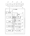
- the play analysis device 100 includes a video reception unit 101, a play analysis unit 102, a UI control unit 103, an analysis image generation unit 104, a video reproduction unit 105, and a storage unit 106.
- the video receiving unit 101 receives the moving image frame 201 transmitted from each of the cameras 3A to 3D and stores it in the storage unit 106.
- the play analysis unit 102 analyzes the player's play using the play video composed of a plurality of continuous video frames 201, and generates play information 202 indicating the player's play status. Then, the play analysis unit 102 stores the play information 202 in the storage unit 106. The details of the play analysis unit 102 will be described later.
- the UI control unit 103 generates the UI 2000 as shown in FIG. 3 and displays it on the display device 4. Further, the UI control unit 103 receives an operation for the UI 2000 through the input device 5.
- the analysis image generation unit 104 generates a situation image 2110 showing the play status of the player selected as the analysis target. Then, the analysis image generation unit 104 generates a play analysis image 2100 including the situation image 2110 and displays it on the UI 2000. The details of the play analysis image 2100 and the analysis image generation unit 104 will be described later.
- the video reproduction unit 105 reproduces the play video 2200 corresponding to the selected situation image 2110 on the UI 2000 according to the operation of the user who selects the situation image 2110 of the play analysis image 2100. Further, the video reproduction unit 105 can adjust the reproduction time according to the operation of the user who sets the reproduction time of the play image 2200, and the set reproduction time can be held as a set value.
- the video reproduction unit 105 may have a function of reproducing the real-time video being shot by the cameras 3A to 3D and the recorded video of the past play as the play video 2200. The details of the video reproduction unit 105 will be described later.
- the play analysis unit 102 applies, for example, the method disclosed in Non-Patent Document 1 to the plurality of moving image frames 201 stored in the storage unit 106, and the time when the moving image frame 201 is shot (hereinafter, “” The three-dimensional position (x, y, z) and velocity of the ball at the "frame time”) are calculated. Then, the play analysis unit 102 generates the ball locus information 203 in association with the frame time, the three-dimensional position of the ball, and the velocity, and stores the ball locus information 203 in the storage unit 106.
- the play analysis unit 102 determines from the ball trajectory information 203 whether or not an action for the ball has occurred. For example, the play analysis unit 102 calculates the trajectory of the ball from the three-dimensional position and velocity of the ball for each frame time included in the ball trajectory information 203. Then, the play analysis unit 102 determines that an action on the ball has occurred when the calculated trajectory change of the ball matches a predetermined condition. When the play analysis unit 102 determines that an action has occurred, the play analysis unit 102 generates action information 204 by associating the frame time in which the action occurred (hereinafter referred to as "action frame time") with the type of the action in which the action occurred. It is stored in the storage unit 106.
- action frame time the frame time in which the action occurred
- the play analysis unit 102 may determine the action type based on the change in the trajectory of the ball, the three-dimensional position and speed of the ball, the rules of sports, and the like.
- Volleyball action types include serve, reception (receive against serve), dig (receive against attack), toss, attack, and block.
- the locus of the ball detected for the first time from the start of analysis has a movement component in the Y-axis direction (the long side direction of the court shown in FIG. 1), and the velocity component of the ball in the Y-axis direction is If it is within the predetermined range, the action type is determined to be "serve".
- the play analysis unit 102 when the trajectory of the ball straddles the coordinates where the net 11 exists on the Y axis after “serving", and the change in the three-dimensional position of the ball changes from descending to ascending (that is,). , When the change in coordinates in the Z-axis direction turns positive), the action type is determined to be “reception”. According to the rules of volleyball, the action to receive "serve” is “reception", so by making a judgment based on such rules, "reception” and “dig” can be distinguished.
- the play analysis unit 102 determines another action type according to the determination criteria according to the rules of sports.
- the occurrence of the action is determined using the three-dimensional information, but the occurrence of the action may be determined using the two-dimensional or one-dimensional information. For example, when determining the occurrence of "serve" under the above-mentioned conditions, it is possible to determine from only the analysis start time and the information in the Y-axis direction without using the information in the X-axis direction and the Z-axis direction.
- the play analysis unit 102 corresponds to a video frame corresponding to the action frame time included in the action information 204 and a frame time in the vicinity of the action frame time from among the plurality of video frames 201 stored in the storage unit 106. Select the video frame to be used as the action frame.
- the play analysis unit 102 detects an area in which a player (person) is photographed (hereinafter referred to as a “player area”) from the action frame. For example, the play analysis unit 102 detects a player area from within the detection area by using a player detection model (neural network) in which a plurality of player images during a competition are learned by deep learning. Then, the play analysis unit 102 recognizes the uniform number of the actor from the action frame.
- a player detection model neural network
- the play analysis unit 102 recognizes the uniform number of an actor from within the detection area by using a model (neural network) for detecting uniform numbers obtained by learning numerical images of uniforms of a plurality of players by deep learning.
- the play analysis unit 102 generates the actor information 205 by associating the action frame time with the recognized uniform number of the actor, and stores it in the storage unit 106.
- the play analysis unit 102 associates the ball trajectory information 203, the action information 204, and the actor information 205 to generate the play information 202 and stores it in the storage unit 106. For example, when the action frame time T and the action type "attack" are associated with each other in the action information 204, and the action frame time T and the uniform number "14" of the actor are associated with each other in the actor information 205, the play is performed.
- the analysis unit 102 generates play information 202 as shown in FIG. That is, as shown in FIG. 4, the play analysis unit 102 provides play information 202 in which the action type “attack” and the actor uniform number “14” are associated with the frame time T of the ball trajectory information 203. Generate.
- the toss play analysis image 2100A is an image for analyzing the toss play of the player (typically a setter) to be analyzed.
- the play analysis image 2100A of the toss is based on the front zone of the court on the target player side. It should be noted that this front zone can be set to an arbitrary area (for example, a default front zone + 1 m extension range) by a user operation.
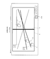
- the serve play analysis image 2100B is an image for analyzing the serve play of the player to be analyzed (typically, a player other than the setter).
- the play analysis image 2100B of Saab is based on the entire court. The user can operate the cursor button 2120 of the play analysis image 2100 to rotate (invert, rotate 90 degrees, etc.) the area of the play analysis image 2100 with respect to the court.
- the analysis image generation unit 104 when the analysis image generation unit 104 generates the toss play analysis image 2100A, the play information 202 in which the uniform number is the number of the player to be analyzed and the action type is "toss" from the storage unit 106. To get.
- the analysis image generation unit 104 identifies the position where the player to be analyzed has tossed from the ball coordinates of the acquired play information 202. Then, as shown in FIG. 5, the analysis image generation unit 104 generates a play analysis image 2100A in which a circular situation image 2110A (2110) is arranged at a position where the target player has tossed.
- the analysis image generation unit 104 when the analysis image generation unit 104 generates the play analysis image 2100B of the serve, the play information 202 in which the uniform number is the number of the player to be analyzed and the action type is "serve" from the storage unit 106. To get. Next, the analysis image generation unit 104 identifies the trajectory of the ball served by the player to be analyzed from the ball coordinates of the acquired play information 202. Then, as shown in FIG. 6, the analysis image generation unit 104 generates a play analysis image 2100B in which the linear situation image 2110B (2110) is arranged on the locus of the ball served by the target player.
- the toss situation image 2110A may have a display form that shows the toss play situation in addition to the tossed position.
- the toss play situation includes, for example, the type of toss, the speed of the ball during toss, the height of the ball during toss, and the moving distance of the ball during toss.
- the serve situation image 2110B may have a display form showing the play status of the serve in addition to the trajectory of the ball.
- the play status of the serve includes, for example, the type of serve, the speed of the serve ball, and the height of the hitting point.
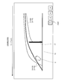
- the display form representing the play status of the toss or serve includes, for example, a shape, a color, a size, and a combination of a plurality of shapes. Further, as shown in FIG. 7, the play analysis image 2100B (2100) of the serve in the form in which the serve passes above the net 11 may be generated in the situation where the court 10 is viewed from the side.
- the play analysis image 2100 of the toss or serve may be displayed by the user performing the following operation.
- Step S11 When the user presses the toss analysis button (not shown) or the serve analysis button (not shown) on the UI 2000, the UI control unit 103 displays a list of players.
- Step S12 The user selects a player to be analyzed for toss or serve from the displayed list of players.
- Step S13 The analysis image generation unit 104 acquires a plurality of play information 202 related to the selected target player from the storage unit 106.
- the analysis image generation unit 104 extracts the toss play information 202 of the action type from the acquired play information 202.
- the analysis image generation unit 104 specifies the ball coordinates of the extracted play information 202 as the position where the toss is performed, and generates the play analysis image 2100A of the toss.
- the analysis image generation unit 104 extracts the play information 202 of the action type from the acquired play information 202.
- the analysis image generation unit 104 identifies the ball coordinates of the extracted play information 202 as the trajectory of the ball at the time of serving, and generates the play analysis image 2100B of the serve.
- the analysis image generation unit 104 displays the generated toss play analysis image 2100A or the serve play analysis image 2100B on the UI2000.
- the video reproduction unit 105 displays, for example, a playback time setting button (not shown) on the UI2000. To do. Then, when the user presses the playback time setting button, the video playback unit 105 displays a list of settable playback times (not shown).
- the playback time displayed in the list includes, for example, the moment when the target player touches the ball, the predetermined time before the target player touches the ball, the predetermined time after the contact with the ball, the predetermined time including before and after the contact with the ball, and There is an entire rally that includes the actions to be analyzed.
- the user may be able to set the playback time in seconds.
- the user does not set the playback time, for example, by holding the automatic playback time from the selected action to the next action as the default, or by holding the user's favorite playback time as the default for each action. , User operation can be omitted.
- the video reproduction unit 105 After the user sets the playback time, when an operation is performed on the predetermined situation image 2110, the video reproduction unit 105 reproduces the play video 2200 corresponding to this operation for the playback time set by the user. If the user does not set the playback time, the video playback unit 105 plays the play video 2200 at the same playback time as the playback performed immediately before. Note that the video reproduction unit 105 may not be provided with a function that allows the user to set the reproduction time, and the play image 2200 may always be reproduced for the same time.
- the video reproduction unit 105 causes a situation.
- the play information 202 used to generate the image 2110A is specified.
- the singular selection operation P1 includes a tap operation with the finger or stylus of the user U, a contact operation for a predetermined time, or a click operation using a mouse.
- the display form of the selected situation image 2110A may be changed so that the user can easily confirm whether or not the predetermined situation image 2110A has been selected. ..
- the display form to be changed includes a color, a size, a line type, and a combination thereof.
- the video reproduction unit 105 recognizes the frame time when the toss was performed based on the specified play information 202. Then, the video reproduction unit 105 reproduces the play video 2200 based on the recognized frame time.
- the video reproduction unit 105 performs each situation image 2110A as in the single selection operation P1. Recognize the frame time when the corresponding toss was made.
- the first plurality selection operation P2 includes an area selection operation that surrounds at least a part of each situation image 2110A by the finger, stylus, or cursor of the user U.
- the loop-shaped selection area mark MC1 indicating the selection area is displayed, or the display form of the selected situation image 2110A is changed.
- the user may be able to easily confirm whether or not the situation image 2110A of the above is selected.
- the display form to be changed includes a color, a size, a line type, and a combination thereof.
- the video reproduction unit 105 continuously reproduces the play video 2200 corresponding to each situation image 2110A one by one based on the recognized frame time. For example, as shown in FIG. 8, the video reproduction unit 105 continuously reproduces the play video 2200 corresponding to the two situation images 2110A one by one.
- the video reproduction unit 105 is tossed.
- the play video 2200 of the serve corresponding to the situation image 2110B is played in the same manner as in the case of playing the play video 2200 of.
- the video reproduction unit 105 recognizes the frame time when the serve corresponding to each situation image 2110B is performed.
- the second multiple selection operation P3 includes a tap operation and a click operation performed at predetermined intervals on the plurality of situation images 2110B.
- the finger or stylus of the user U can be used for the tap operation, and the mouse can be used for the click operation.
- the second multiple selection operation P3 the user can easily confirm whether or not the predetermined situation image 2110B has been selected by changing the display form of the selected situation image 2110B. You may be able to do it.
- the display form to be changed includes a color, a size, a line type, and a combination thereof.
- FIG. 6 illustrates a configuration in which the line is thickened.
- the video reproduction unit 105 arranges and simultaneously reproduces the play video 2200 corresponding to each situation image 2110B based on the recognized frame time. For example, as shown in FIG. 9, the video reproduction unit 105 simultaneously reproduces the play video 2200 corresponding to the two situation images 2110B side by side. In this simultaneous reproduction, the two images to be reproduced are simultaneously reproduced based on the moment when the action occurs. In this way, when two playback target videos are simultaneously played back based on the moment when the action occurs, for example, if the playback time is set from 2 seconds before the moment of the selected action to 1 second after the next action, The playback end timing of the video to be played back may be different.
- one of the moving images to be compared may be slow-played or quick-played to align the timing from the start to the end. This makes it possible to compare the differences in the postures of the athletes more clearly.
- the speed ratio of slow playback and quick playback may be specified on the screen to clarify the difference in action speed.
- the single selection operation P1 relating to toss and serve may be an area selection operation surrounding at least a part of one situation image 2110.
- the singular selection operations P1 for toss and serve may be the same or different.
- At least one of the first plurality selection operation P2 and the second multiple selection operation P3 may be an operation of surrounding one situation image 2110 at a predetermined interval.
- the play images 2200 may be played side by side at the same time or may be played back continuously.
- the first multiple selection operation P3 for the serve situation image 2110B is performed, the play video 2200 may be continuously reproduced.
- the play video 2200 may be arranged one above the other, or for example, one of the two play video 2200 may be made translucent and the other video may be superimposed and simultaneously played.
- the play analysis unit 102 generates play information 202 using the moving image frame 201 stored in the storage unit 106 and stores it in the storage unit 106 (S1).
- the analysis image generation unit 104 recognizes the player to be analyzed and the action type according to the user's operation (S2). Then, the analysis image generation unit 104 generates a play analysis image 2100 corresponding to the player to be analyzed and the action type, and displays it on the UI 2000 (S3).
- the video reproduction unit 105 sets the reproduction time of the play video 2200 according to the operation of the user (S4).
- the setting of the reproduction time can be omitted. In that case, the preset default playback time is read and automatically set. This default playback time can be changed according to the user's operation.
- the video reproduction unit 105 recognizes the user's situation image 2110 selection operation (S5).
- the video reproduction unit 105 determines the play image 2200 to be reproduced and the reproduction form (continuous reproduction or simultaneous reproduction when reproducing a plurality of play images 2200) based on the selection operation recognized in S5. Identify (S6).
- the video reproduction unit 105 reproduces the play video 2200 in the reproduction mode specified in S6 and the reproduction time set in S4 (S7).
- the play analysis device 100 receives the video frame 201 from the cameras 3A to 3D, analyzes the player's play using the play video 2200 composed of the plurality of video frames 201, and obtains the play information 202. Generate. Next, the play analysis device 100 generates a situation image 2110 showing the play situation based on the play information 202 and displays it on the display device 4. Then, the play analysis device 100 reproduces the play video 2200 corresponding to the situation image 2110 according to the operation of the user U who selects the situation image 2110. For example, when the user U performs the single selection operation P1 for selecting one situation image 2110A, the play analysis device 100 reproduces the play video 2200 corresponding to the situation image 2110A.
- the user U can immediately confirm the play video 2200 to be analyzed after the selection operation of the situation image 2110 showing the play analysis result of the sport.
- the play analyzer 100 adjusts the playback time of the play video 2200 according to the operation of the user who sets the playback time of the play video 2200.
- the user U can selectively confirm the play scene that he / she wants to confirm.
- the play analyzer 100 corresponds to each of the plurality of situation images 2110 according to the first multiple selection operation P2 of the user U who selects an area including the plurality of situation images 2110. 2200 is continuously reproduced.
- the user U can continuously confirm the plurality of play images 2200 by a simple operation of performing the first multiple selection operation P2. Further, if an operation surrounding a plurality of situation images 2110 is applied as the first multiple selection operation P2, the user U can confirm the plurality of play images 2200 with only one simple operation.
- the play analyzer 100 displays the play video 2200 corresponding to each of the plurality of situation images 2110 according to the second multiple selection operation P3 of the user who individually selects the plurality of situation images 2110. Play at the same time.
- the user U can check a plurality of play images 2200 at the same time by a simple operation of performing the second multiple selection operation P3.
- the user U can compare the differences in the play of the plurality of play images 2200, and can easily grasp the good points and the bad points of the play.
- the situation image 2110 having the maximum length of a predetermined value or more like the linear situation image 2110B relating to the serve, if the tap operation is applied as the second multiple selection operation P3, the situation image 2110 The operation range can be made smaller than that of the operation surrounding.
- the one shown in FIG. 11 can be exemplified as a sport in which the content of the technique can be displayed as a situation image.
- the technique shown in FIG. 11 can represent the type of technique, the situation when the technique is applied, and the like depending on the display form of the situation image such as a circle or a polygon.
- the one shown in FIG. 12 can be exemplified as a sport in which a graph-format situation image can be used.
- the technique shown in FIG. 6 of the above-described embodiment the technique shown in FIG.
- the play analysis unit 102 may generate the play information 202 according to the contents of various sports.
- the video reproduction unit 105 follows the operation of the user who selects a part of the movement locus.
- the play video 2200 corresponding to a part of the selected movement locus may be reproduced.
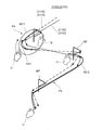
- the analysis image generation unit 104 As shown in FIG. 13, linear situation images 2110C, 2110D (2110) showing the skiing situation of the athlete in the ski rotation event based on the play information 202. And the play analysis image 2100C (2100) in which the flag mark MF is arranged are displayed on the UI2000.
- the video reproduction unit 105 causes the frame of the sliding section RS1 corresponding to the selected part. Recognize the time.
- the first partial selection operation P4 includes an area selection operation that surrounds a part of the situation images 2110C and 2110D by the finger, stylus, or cursor of the user U.
- the loop-shaped selection area mark MC1 indicating the selection area is displayed, or the display form of the selection portion on the situation images 2110C and 2110D is changed. This may allow the user to easily confirm the selection range.
- the display form to be changed includes a color, a size, a line type, and a combination thereof. Then, as shown in FIG. 14, the video reproduction unit 105 simultaneously reproduces the play video 2200 of the gliding section RS1 selected in the first partial selection operation P4 side by side.
- the video reproduction unit 105 recognizes the second partial selection operation P5 different from the first partial selection operation P4 in the state where the play analysis images 2100C and 2100D shown in FIG. 13 are displayed.
- the second partial selection operation P5 includes a tracing operation that traces a part of the situation images 2110C and 2110D.
- the trace mark MC2 indicating the traced trajectory is displayed, or the display form of the selected portion on the situation images 2110C and 2110D is changed. , The selection range may be easily confirmed by the user.
- the video reproduction unit 105 continuously reproduces the play video 2200 of the traced gliding section.
- the play video 2200 may be continuously reproduced, or the second partial selection operation P5 When is recognized, the play video 2200 may be played back at the same time.
- the situation image 2110 that can be collectively selected may be the analysis result of a common action type in a plurality of different play images 2200 of the same sport.
- the situation image 2110 that can be collectively selected may be the analysis result of the common action type “toss” in the plurality of different play images 2200 as described above.
- the situation image 2110 that can be collectively selected is an analysis result of a common action type "turn” in a plurality of different play images 2200 as described above. You can do it.
- the situation image 2110 that can be collectively selected may be the analysis result of the common action type "Lutz" in the plurality of different play images 2200.
- the user can easily compare and reproduce a plurality of different play images 2200 of a common action type.
- the plurality of play images 2200 reproduced based on one play analysis image 2100 may be played by different players, or may be played by the same player or different players in different games. It may be a play or a play of a different action type.
- a flow line image showing the movement locus of the ball can be superimposed.
- a directing effect can be obtained on the reproduced video, and the user viewing the video. Can instantly grasp the situation of the entire play such as serve and attack.
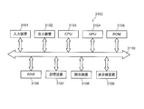
- FIG. 15 is a diagram showing a hardware configuration of a computer that realizes the functions of each device by a program.
- the computer 3100 includes an input device 3101 such as a keyboard or mouse and a touch pad, an output device 3102 such as a display or a speaker, a CPU (Central Processing Unit) 3103, a GPU (Graphics Processing Unit) 3104, and a ROM (Read Only Memory) 3105.
- Read information from a recording medium such as RAM (RandomAccessMemory) 3106, hard disk device or storage device 3107 such as SSD (SolidStateDrive), DVD-ROM (DigitalVersatileDiskReadOnlyMemory) or USB (UniversalSerialBus) memory. It includes a reading device 3108 and a transmitting / receiving device 3109 that communicates via a network, and each unit is connected by a bus 3110.
- the reading device 3108 reads the program from the recording medium on which the program for realizing the function of each of the above devices is recorded, and stores the program in the storage device 3107.
- the transmission / reception device 3109 communicates with the server device connected to the network, and stores the program downloaded from the server device for realizing the function of each device in the storage device 3107.
- the CPU 3103 copies the program stored in the storage device 3107 to the RAM 3106, and sequentially reads and executes the instructions included in the program from the RAM 3106, whereby the functions of the above devices are realized.
- LSI is an integrated circuit. These may be individually integrated into one chip, or may be integrated into one chip so as to include a part or all of them. Although it is referred to as LSI here, it may be referred to as IC, system LSI, super LSI, or ultra LSI depending on the degree of integration.
- the method of making an integrated circuit is not limited to LSI, and may be realized by a dedicated circuit or a general-purpose processor.
- An FPGA Field Programmable Gate Array
- a reconfigurable processor that can reconfigure the connection and settings of the circuit cells inside the LSI may be used.
- One aspect of the disclosure is useful for systems for analyzing sports.
- Play analysis system 3 (3A, 3B, 3C, 3D) Camera 4 Display device 5
- Input device 100
- Play analyzer 101
- Video receiver 102
- Play analysis unit 103
- UI control unit 104
- Analysis image generation unit 105
- Video playback unit 106
- Storage unit 201
- Video frame 202
- Play information 203
- Ball trajectory information 204
- Action information 205
- Actor information 2100, 2100A, 2100B, 2100C Play analysis image 2110, 2110A, 2110B, 2110C, 2110D
- Situation image 2200 Play video
- Selection area mark MC2 Trace mark P1 Single selection operation
- P2 1st multiple selection operation
- P3 2nd multiple selection operation
- P4 1st partial selection operation
- P5 2nd partial selection operation
Abstract
This play analysis apparatus is provided with: a play analysis unit that generates play information by analyzing a play of a player by using a play video; an analysis image generation unit that generates, on the basis of the play information, a state image 2110 representing a play state of the player, and that displays the state image on a display device; and a video reproduction unit that reproduces a play video corresponding to the state image 2110 in accordance with an operation of a user for selecting the state image 2110.
Description
本開示は、スポーツのプレイ分析装置、及び、プレイ分析方法に関する。
This disclosure relates to a sports play analyzer and a play analysis method.
従来より、バレーボール分析ソフトウェアとして「Data Volley」が知られている。Data Volleyはこのソフトウェアに精通したアナリストによって使用され、当該アナリストが、主観的判断に基づいて、チームの選手の状況を示すデータをData Volleyに入力する。
Conventionally, "Data Volley" has been known as volleyball analysis software. Data Volley is used by analysts who are familiar with the software, who, based on subjective judgment, enter data into Data Volley that indicates the status of the players on the team.
特許文献1には、アナリストの操作性を向上させたスカウティングシステムが開示されている。具体的には、特許文献1には、画像解析を用いて各選手の位置情報を取得し、入力された選手状況と、各選手のそれぞれの位置情報と、所望のシーンの静止画像とを関連付けて記憶装置にデータベースを構築し、各選手の各位置、所望のシーンの静止画像、選手状況を表示することが開示されている。この発明により、スコアラー(アナリスト)のトレーニングが必要であり、各選手の位置情報が視覚による主観的判断により入力されているためにデータ精度が低いというData Volleyのソフトウェアの問題点を解決できる。
Patent Document 1 discloses a scouting system with improved operability for analysts. Specifically, in Patent Document 1, the position information of each player is acquired by using image analysis, and the input player situation, each position information of each player, and a still image of a desired scene are associated with each other. It is disclosed that a database is constructed in a storage device to display each position of each player, a still image of a desired scene, and a player situation. According to the present invention, it is possible to solve the problem of Data Volley software that training of a scorer (analyst) is required and the data accuracy is low because the position information of each player is input by visual subjective judgment.
また、従来のバレーボール分析ソフトウェアは、サーブに対するレシーブのシーンを撮影した映像を順次取り込み、各選手の技能評価を入力し、各選手のレシーブ回数及びレシーブ成功率等を集計及び表示する。ユーザ(チームの監督等)は、この集計結果を見て、チームの強み及び弱みを分析する。
In addition, the conventional volleyball analysis software sequentially captures the images of the receive scenes for the serve, inputs the skill evaluation of each player, and aggregates and displays the number of receive times and the receive success rate of each player. The user (team manager, etc.) analyzes the strengths and weaknesses of the team by looking at the aggregated results.
上述のような従来の技術では、例えば、セッターのトスの瞬間の画像を順次取り込み、各選手の技能評価を入力することで、各選手の各位置、所望のシーンの静止画像、プレイ状況等を表示できる。しかし、各選手の技能評価等に基づき得られた分析結果(分析情報や分析画像)から、当該分析対象のシーンを直ちに確認することは困難である。
In the conventional technique as described above, for example, by sequentially capturing images of the moment of toss of the setter and inputting the skill evaluation of each player, each position of each player, a still image of a desired scene, a play situation, etc. can be obtained. Can be displayed. However, it is difficult to immediately confirm the scene to be analyzed from the analysis results (analysis information and analysis images) obtained based on the skill evaluation of each athlete.
本開示の目的は、スポーツのプレイ分析結果から、当該分析対象のシーンを直ちに確認できるプレイ分析装置及びプレイ分析方法を提供することにある。
The purpose of the present disclosure is to provide a play analysis device and a play analysis method that can immediately confirm the scene to be analyzed from the play analysis result of sports.
本開示の一態様に係るプレイ分析装置は、スポーツのプレイを分析するプレイ分析装置であって、プレイ映像を用いて選手のプレイを分析してプレイ情報を生成するプレイ分析部と、前記プレイ情報に基づき、前記選手のプレイ状況を表わす状況画像を生成して表示装置に表示する分析画像生成部と、前記状況画像を選択するユーザの操作にしたがって、前記状況画像に対応するプレイ映像を再生する映像再生部と、を備える。
The play analysis device according to one aspect of the present disclosure is a play analysis device that analyzes sports play, and includes a play analysis unit that analyzes a player's play using a play image and generates play information, and the play information. Based on the above, the analysis image generation unit that generates a situation image showing the play situation of the player and displays it on the display device, and the play image corresponding to the situation image are reproduced according to the operation of the user who selects the situation image. It is equipped with a video playback unit.
本開示の一態様に係るプレイ分析方法は、スポーツのプレイを分析するプレイ分析方法であって、プレイ映像を用いて選手のプレイを分析してプレイ情報を生成し、前記プレイ情報に基づき、前記選手のプレイ状況を表わす状況画像を生成して表示装置に表示し、前記状況画像を選択するユーザの操作にしたがって、前記状況画像に対応するプレイ映像を再生する。
The play analysis method according to one aspect of the present disclosure is a play analysis method for analyzing sports play, in which a player's play is analyzed using a play video to generate play information, and based on the play information, the play analysis method is described. A situation image showing the player's play situation is generated and displayed on the display device, and the play video corresponding to the situation image is reproduced according to the operation of the user who selects the situation image.
なお、これらの包括的又は具体的な態様は、システム、装置、方法、集積回路、コンピュータプログラム、又は、記録媒体で実現されてもよく、システム、装置、方法、集積回路、コンピュータプログラムおよび記録媒体の任意な組み合わせで実現されてもよい。
Note that these comprehensive or specific embodiments may be realized in a system, device, method, integrated circuit, computer program, or recording medium, and the system, device, method, integrated circuit, computer program, and recording medium. It may be realized by any combination of.
本開示によれば、スポーツのプレイ分析結果から、当該分析対象のシーンを直ちに確認できる。
According to this disclosure, the scene to be analyzed can be immediately confirmed from the sports play analysis result.
以下、図面を適宜参照して、本発明の実施の形態について、詳細に説明する。但し、必要以上に詳細な説明は省略する場合がある。例えば、既によく知られた事項の詳細説明や実質的に同一の構成に対する重複説明を省略する場合がある。これは、以下の説明が不必要に冗長になるのを避け、当業者の理解を容易にするためである。
Hereinafter, embodiments of the present invention will be described in detail with reference to the drawings as appropriate. However, more detailed explanation than necessary may be omitted. For example, detailed explanations of already well-known matters and duplicate explanations for substantially the same configuration may be omitted. This is to avoid unnecessary redundancy of the following description and to facilitate the understanding of those skilled in the art.
なお、添付図面および以下の説明は、当業者が本開示を十分に理解するために提供されるのであって、これらにより特許請求の範囲に記載の主題を限定することは意図されていない。
It should be noted that the accompanying drawings and the following description are provided for those skilled in the art to fully understand the present disclosure, and are not intended to limit the subject matter described in the claims.
(実施の形態)
<プレイ分析システム>
まず、図1を参照しながら、一実施の形態に係るプレイ分析システムの概要について説明する。 (Embodiment)
<Play analysis system>
First, the outline of the play analysis system according to the embodiment will be described with reference to FIG.
<プレイ分析システム>
まず、図1を参照しながら、一実施の形態に係るプレイ分析システムの概要について説明する。 (Embodiment)
<Play analysis system>
First, the outline of the play analysis system according to the embodiment will be described with reference to FIG.
プレイ分析システム1は、スポーツを撮影したプレイ映像を分析し、当該分析結果に基づくプレイ映像を再生するシステムである。スポーツは、球技であってもよいし、球技でなくてもよい。球技に用いられる移動体は、典型的にはボールであるが、バドミントンに用いられるシャトル等であってもよい。本実施の形態では、球技の1つであるバレーボールを例に説明する。ただし、プレイ分析システム1は、サッカー、野球、卓球、バスケットボール、テニス、ラグビー、アメリカンフットボール、ラクロス、又はバドミントン等の球技全般や、スキー、スキージャンプ、陸上競技、柔道等の球技以外のスポーツに適用可能である。また、プレイ分析システム1は、アイスホッケーのパック、カーリングのストーン、アーチェリーの矢、陸上競技のやり、ハンマー等、「球」の概念に当てはまらない形状の移動体にも適用可能である。すなわち、プレイ分析システム1は、複数人から構成されるチームや個人がアクションを行うことにより点数又は勝敗が決定されるスポーツであれば、どのようなスポーツにも適用可能である。
The play analysis system 1 is a system that analyzes a play video of a sport and reproduces a play video based on the analysis result. The sport may or may not be a ball game. The moving body used in the ball game is typically a ball, but may be a shuttle or the like used for badminton. In the present embodiment, volleyball, which is one of the ball games, will be described as an example. However, the play analysis system 1 is applied to all ball games such as soccer, baseball, table tennis, basketball, tennis, rugby, American football, lacrosse, or badminton, and sports other than ball games such as skiing, ski jumping, athletics, and judo. It is possible. The play analysis system 1 can also be applied to moving objects having shapes that do not fit the concept of "sphere", such as ice hockey pucks, curling stones, archery arrows, athletic spears, and hammers. That is, the play analysis system 1 can be applied to any sport as long as the score or the victory or defeat is determined by the action of a team or an individual composed of a plurality of people.
プレイ分析システム1は、複数のカメラ3(3A、3B、3C、3D)と、表示装置4と、入力装置5と、プレイ分析装置100と、を備える。
The play analysis system 1 includes a plurality of cameras 3 (3A, 3B, 3C, 3D), a display device 4, an input device 5, and a play analysis device 100.
複数のカメラ3は、それぞれ異なる位置に設置される。例えば、図1に示すように、各カメラ3は、高所からコート10を異なる視点(画角)で撮影できる位置に設置される。なお、図1ではカメラ3が4台であるが、本実施の形態はこれに限られず、カメラ3は、2台以上であれば何台でもよい。2台以上のカメラ3を用いることにより、ボールの3次元位置を算出できる。
The plurality of cameras 3 are installed at different positions. For example, as shown in FIG. 1, each camera 3 is installed at a position where the court 10 can be photographed from a high place with different viewpoints (angles of view). Although the number of cameras 3 is four in FIG. 1, the present embodiment is not limited to this, and the number of cameras 3 may be any number as long as it is two or more. By using two or more cameras 3, the three-dimensional position of the ball can be calculated.
各カメラ3は、プレイ分析装置100と有線又は無線を介して通信可能に接続されている。各カメラ3は、球技中の状況を撮影し、撮影画像を生成する。そして、各カメラ3は、複数の撮影画像から動画フレーム201(図2参照)を生成する。そして、各カメラ3は、動画フレーム201をプレイ分析装置100へ送信する。動画フレーム201は、複数の撮影画像が、例えば、MP4、H.264、H.265、又は、Motion JPEG等の規格に基づいて圧縮されたものであってよい。
Each camera 3 is communicably connected to the play analyzer 100 via wire or wireless. Each camera 3 captures the situation during the ball game and generates a captured image. Then, each camera 3 generates a moving image frame 201 (see FIG. 2) from a plurality of captured images. Then, each camera 3 transmits the moving image frame 201 to the play analyzer 100. In the moving image frame 201, a plurality of captured images are displayed, for example, MP4, H.M. 264, H. It may be compressed based on a standard such as 265 or Motion JPEG.
表示装置4は、プレイ分析装置100と有線又は無線を介して通信可能に接続されており、プレイ分析装置100から出力される画像を表示する。表示装置4は、例えば、液晶ディスプレイ又は有機ELディスプレイ等である。
The display device 4 is communicably connected to the play analyzer 100 via a wired or wireless device, and displays an image output from the play analyzer 100. The display device 4 is, for example, a liquid crystal display or an organic EL display.
入力装置5は、プレイ分析装置100と有線又は無線を介して通信可能に接続されており、ユーザからの操作を受け付け、その操作情報をプレイ分析装置100へ送信する。入力装置5は、例えば、キーボード、マウス、マイク及び/又はタッチパネル等である。なお、入力装置5及び表示装置4は一体型の装置であってもよい。
The input device 5 is communicably connected to the play analysis device 100 via wire or wireless, receives an operation from the user, and transmits the operation information to the play analysis device 100. The input device 5 is, for example, a keyboard, a mouse, a microphone and / or a touch panel. The input device 5 and the display device 4 may be integrated devices.
プレイ分析装置100は、各カメラ3が撮影した動画フレームを用いて、ボールに対してアクションを行った選手を特定する。バレーボールの場合、ボールに対して行われるアクションには、サーブ、レセプション、ディグ、トス、アタック、及びブロック等がある。以下、ボールに対してアクションを行った選手を、「アクター」と表現する場合がある。
The play analysis device 100 identifies a player who has performed an action on the ball by using a moving image frame taken by each camera 3. In the case of volleyball, the actions taken on the ball include serve, reception, dig, toss, attack, and block. Hereinafter, the player who has performed an action on the ball may be referred to as an "actor".
なお、本実施の形態では、図1に示すように、コート10の面の中心点を原点Oとし、コート10の面と平行かつネット11と平行な軸をX軸、コート10の面と平行かつネット11と垂直な軸をY軸、コート10の面と垂直な軸をZ軸とする。X軸は、審判12から離れる方向を正方向、審判12に近づく方向を負方向とする。Y軸は、審判12から見て左方向を正方向、右方向を負方向とする。Z軸は、コート10の面から離れる方向を正方向とする。つまりZ軸の座標は、コート10の面からの高さに相当する。
In the present embodiment, as shown in FIG. 1, the center point of the surface of the coat 10 is set as the origin O, the axis parallel to the surface of the coat 10 and parallel to the net 11 is the X axis, and parallel to the surface of the coat 10. The axis perpendicular to the net 11 is the Y axis, and the axis perpendicular to the surface of the coat 10 is the Z axis. The X-axis has a positive direction away from the referee 12 and a negative direction closer to the referee 12. The Y-axis has a positive direction in the left direction and a negative direction in the right direction when viewed from the referee 12. The Z-axis has a positive direction away from the surface of the coat 10. That is, the coordinates of the Z axis correspond to the height from the surface of the court 10.
<プレイ分析装置>
次に、図2を参照しながら、プレイ分析装置100について説明する。 <Play analyzer>
Next, theplay analyzer 100 will be described with reference to FIG.
次に、図2を参照しながら、プレイ分析装置100について説明する。 <Play analyzer>
Next, the
プレイ分析装置100は、映像受信部101と、プレイ分析部102と、UI制御部103と、分析画像生成部104と、映像再生部105と、記憶部106とを備える。
The play analysis device 100 includes a video reception unit 101, a play analysis unit 102, a UI control unit 103, an analysis image generation unit 104, a video reproduction unit 105, and a storage unit 106.
映像受信部101は、各カメラ3A~3Dから送信される動画フレーム201を受信し、記憶部106に格納する。
The video receiving unit 101 receives the moving image frame 201 transmitted from each of the cameras 3A to 3D and stores it in the storage unit 106.
プレイ分析部102は、複数の連続する動画フレーム201で構成されるプレイ映像を用いて選手のプレイを分析し、選手のプレイ状況を表わすプレイ情報202を生成する。そして、プレイ分析部102は、プレイ情報202を記憶部106に格納する。なお、プレイ分析部102の詳細については後述する。
The play analysis unit 102 analyzes the player's play using the play video composed of a plurality of continuous video frames 201, and generates play information 202 indicating the player's play status. Then, the play analysis unit 102 stores the play information 202 in the storage unit 106. The details of the play analysis unit 102 will be described later.
UI制御部103は、図3に示すようなUI2000を生成し、表示装置4に表示する。また、UI制御部103は、入力装置5を通じて、UI2000に対する操作を受け付ける。
The UI control unit 103 generates the UI 2000 as shown in FIG. 3 and displays it on the display device 4. Further, the UI control unit 103 receives an operation for the UI 2000 through the input device 5.
分析画像生成部104は、分析対象に選択された選手のプレイ状況を表わす状況画像2110を生成する。そして、分析画像生成部104は、状況画像2110を含むプレイ分析画像2100を生成し、UI2000に表示する。なお、プレイ分析画像2100及び分析画像生成部104の詳細については後述する。
The analysis image generation unit 104 generates a situation image 2110 showing the play status of the player selected as the analysis target. Then, the analysis image generation unit 104 generates a play analysis image 2100 including the situation image 2110 and displays it on the UI 2000. The details of the play analysis image 2100 and the analysis image generation unit 104 will be described later.
映像再生部105は、プレイ分析画像2100の状況画像2110を選択するユーザの操作にしたがって、当該選択された状況画像2110に対応するプレイ映像2200をUI2000上で再生する。また、映像再生部105は、プレイ映像2200の再生時間を設定するユーザの操作にしたがって、再生時間を調整することができ、設定された再生時間は設定値として保持しておくことができる。映像再生部105は、カメラ3A~3Dが撮影中のリアルタイム映像や、過去のプレイの録画映像を、プレイ映像2200として再生する機能を有していてもよい。なお、映像再生部105の詳細については後述する。
The video reproduction unit 105 reproduces the play video 2200 corresponding to the selected situation image 2110 on the UI 2000 according to the operation of the user who selects the situation image 2110 of the play analysis image 2100. Further, the video reproduction unit 105 can adjust the reproduction time according to the operation of the user who sets the reproduction time of the play image 2200, and the set reproduction time can be held as a set value. The video reproduction unit 105 may have a function of reproducing the real-time video being shot by the cameras 3A to 3D and the recorded video of the past play as the play video 2200. The details of the video reproduction unit 105 will be described later.
<プレイ分析部の詳細>
次に、プレイ分析部102の詳細について説明する。 <Details of Play Analysis Department>
Next, the details of theplay analysis unit 102 will be described.
次に、プレイ分析部102の詳細について説明する。 <Details of Play Analysis Department>
Next, the details of the
まず、プレイ分析部102は、記憶部106に格納された複数の動画フレーム201に対して、例えば非特許文献1に開示されている手法を適用し、動画フレーム201が撮影された時刻(以下「フレーム時刻」という)におけるボールの3次元位置(x,y,z)及び速度を算出する。そして、プレイ分析部102は、フレーム時刻とボールの3次元位置と速度とを対応付けてボール軌跡情報203を生成し、記憶部106に格納する。
First, the play analysis unit 102 applies, for example, the method disclosed in Non-Patent Document 1 to the plurality of moving image frames 201 stored in the storage unit 106, and the time when the moving image frame 201 is shot (hereinafter, “” The three-dimensional position (x, y, z) and velocity of the ball at the "frame time") are calculated. Then, the play analysis unit 102 generates the ball locus information 203 in association with the frame time, the three-dimensional position of the ball, and the velocity, and stores the ball locus information 203 in the storage unit 106.
また、プレイ分析部102は、ボール軌跡情報203から、ボールに対するアクションが発生したか否かを判定する。例えば、プレイ分析部102は、ボール軌跡情報203に含まれるフレーム時刻毎のボールの3次元位置及び速度からボールの軌跡を算出する。そして、プレイ分析部102は、その算出したボールの軌跡変化が所定の条件に合致した場合、ボールに対するアクションが発生したと判定する。プレイ分析部102は、アクションが発生したと判定した場合、アクションが発生したフレーム時刻(以下「アクションフレーム時刻」という)と、その発生したアクションの種別とを対応付けてアクション情報204を生成し、記憶部106に格納する。
Further, the play analysis unit 102 determines from the ball trajectory information 203 whether or not an action for the ball has occurred. For example, the play analysis unit 102 calculates the trajectory of the ball from the three-dimensional position and velocity of the ball for each frame time included in the ball trajectory information 203. Then, the play analysis unit 102 determines that an action on the ball has occurred when the calculated trajectory change of the ball matches a predetermined condition. When the play analysis unit 102 determines that an action has occurred, the play analysis unit 102 generates action information 204 by associating the frame time in which the action occurred (hereinafter referred to as "action frame time") with the type of the action in which the action occurred. It is stored in the storage unit 106.
なお、プレイ分析部102は、ボールの軌跡変化、ボールの3次元位置及び速度、並びに、スポーツのルール等に基づいて、アクション種別を判定してもよい。バレーボールのアクション種別には、サーブ、レセプション(サーブに対するレシーブ)、ディグ(アタックに対するレシーブ)、トス、アタック、及びブロック等がある。例えば、プレイ分析部102は、解析開始から初めて検出されたボールの軌跡がY軸方向(図1に示すコートの長辺方向)の移動成分を有し、当該Y軸方向のボールの速度成分が所定の範囲内である場合、アクション種別を「サーブ」と判定する。他の例として、プレイ分析部102は、「サーブ」後にボールの軌跡がY軸においてネット11の存在する座標を跨ぎ、かつ、ボールの3次元位置の変化が下降から上昇に転じた場合(すなわち、Z軸方向の座標の変化がプラスに転じた場合)、アクション種別を「レセプション」と判定する。バレーボールのルール上、「サーブ」を受けるアクションは「レセプション」であるので、このようなルールに基づく判定を行うことにより、「レセプション」と「ディグ」を区別できる。
The play analysis unit 102 may determine the action type based on the change in the trajectory of the ball, the three-dimensional position and speed of the ball, the rules of sports, and the like. Volleyball action types include serve, reception (receive against serve), dig (receive against attack), toss, attack, and block. For example, in the play analysis unit 102, the locus of the ball detected for the first time from the start of analysis has a movement component in the Y-axis direction (the long side direction of the court shown in FIG. 1), and the velocity component of the ball in the Y-axis direction is If it is within the predetermined range, the action type is determined to be "serve". As another example, in the play analysis unit 102, when the trajectory of the ball straddles the coordinates where the net 11 exists on the Y axis after "serving", and the change in the three-dimensional position of the ball changes from descending to ascending (that is,). , When the change in coordinates in the Z-axis direction turns positive), the action type is determined to be "reception". According to the rules of volleyball, the action to receive "serve" is "reception", so by making a judgment based on such rules, "reception" and "dig" can be distinguished.
同様に、プレイ分析部102は、ボールの軌跡変化や選手の動き等が所定の条件に合致する場合に、スポーツのルールに準じた判定基準によって他のアクション種別を判定する。
Similarly, when the change in the trajectory of the ball, the movement of the player, or the like meets the predetermined conditions, the play analysis unit 102 determines another action type according to the determination criteria according to the rules of sports.
なお、上記では、3次元の情報を用いてアクションの発生を判定しているが、2次元又は1次元の情報を用いてアクションの発生を判定してもよい。例えば、上述した条件で「サーブ」の発生を判定する場合、X軸方向とZ軸方向の情報を用いずに、解析開始の時刻とY軸方向の情報のみから判定可能である。
In the above, the occurrence of the action is determined using the three-dimensional information, but the occurrence of the action may be determined using the two-dimensional or one-dimensional information. For example, when determining the occurrence of "serve" under the above-mentioned conditions, it is possible to determine from only the analysis start time and the information in the Y-axis direction without using the information in the X-axis direction and the Z-axis direction.
プレイ分析部102は、記憶部106に格納されている複数の動画フレーム201の中から、アクション情報204に含まれるアクションフレーム時刻に対応する動画フレームと、当該アクションフレーム時刻の近傍のフレーム時刻に対応する動画フレームとを、アクションフレームとして選択する。次に、プレイ分析部102は、アクションフレームから選手(人物)が撮影されている領域(以下「選手領域」という)を検出する。例えば、プレイ分析部102は、競技中の複数の選手画像をディープラーニングによって学習させた選手検出用のモデル(ニューラルネットワーク)を用いて、検出領域内から選手領域を検出する。そして、プレイ分析部102は、アクションフレームから、アクターのユニフォーム番号を認識する。例えば、プレイ分析部102は、複数の選手のユニフォームの数字画像をディープラーニングによって学習させたユニフォーム番号検出用のモデル(ニューラルネットワーク)を用いて、検出領域内から、アクターのユニフォーム番号を認識する。次に、プレイ分析部102は、アクションフレーム時刻と、認識したアクターのユニフォーム番号とを対応付けてアクター情報205を生成し、記憶部106に格納する。
The play analysis unit 102 corresponds to a video frame corresponding to the action frame time included in the action information 204 and a frame time in the vicinity of the action frame time from among the plurality of video frames 201 stored in the storage unit 106. Select the video frame to be used as the action frame. Next, the play analysis unit 102 detects an area in which a player (person) is photographed (hereinafter referred to as a “player area”) from the action frame. For example, the play analysis unit 102 detects a player area from within the detection area by using a player detection model (neural network) in which a plurality of player images during a competition are learned by deep learning. Then, the play analysis unit 102 recognizes the uniform number of the actor from the action frame. For example, the play analysis unit 102 recognizes the uniform number of an actor from within the detection area by using a model (neural network) for detecting uniform numbers obtained by learning numerical images of uniforms of a plurality of players by deep learning. Next, the play analysis unit 102 generates the actor information 205 by associating the action frame time with the recognized uniform number of the actor, and stores it in the storage unit 106.
そして、プレイ分析部102は、ボール軌跡情報203と、アクション情報204と、アクター情報205とを対応付けて、プレイ情報202を生成し、記憶部106に格納する。例えば、アクション情報204においてアクションフレーム時刻Tとアクション種別「アタック」とが対応付けられており、アクター情報205においてアクションフレーム時刻Tとアクターのユニフォーム番号「14」とが対応付けられている場合、プレイ分析部102は、図4に示すようなプレイ情報202を生成する。すなわち、プレイ分析部102は、図4に示すように、ボール軌跡情報203のフレーム時刻Tに対して、アクション種別「アタック」と、アクターのユニフォーム番号「14」とを対応付けたプレイ情報202を生成する。これにより、ユーザ又は他の装置は、プレイ情報202を用いて、フレーム時刻Tにおいて、ユニフォーム番号「14」の選手(アクター)が、3次元位置(xT,yT,zT)のボールに対して、速度「ST(km/h)」の「アタック」を行ったことを知ることができる。
Then, the play analysis unit 102 associates the ball trajectory information 203, the action information 204, and the actor information 205 to generate the play information 202 and stores it in the storage unit 106. For example, when the action frame time T and the action type "attack" are associated with each other in the action information 204, and the action frame time T and the uniform number "14" of the actor are associated with each other in the actor information 205, the play is performed. The analysis unit 102 generates play information 202 as shown in FIG. That is, as shown in FIG. 4, the play analysis unit 102 provides play information 202 in which the action type “attack” and the actor uniform number “14” are associated with the frame time T of the ball trajectory information 203. Generate. Thus, a user or other device, using the play information 202, the frame time T, the player's shirt number "14" (actors) are three-dimensional position (x T, y T, z T) to the ball of On the other hand, it can be known that the "attack" of the speed " ST (km / h)" has been performed.
<プレイ分析画像>
次に、図5~図7を参照して、プレイ分析画像2100の具体例として、トスのプレイ分析画像2100A及びサーブのプレイ分析画像2100Bについて説明する。 <Play analysis image>
Next, with reference to FIGS. 5 to 7, as a specific example of theplay analysis image 2100, the toss play analysis image 2100A and the serve play analysis image 2100B will be described.
次に、図5~図7を参照して、プレイ分析画像2100の具体例として、トスのプレイ分析画像2100A及びサーブのプレイ分析画像2100Bについて説明する。 <Play analysis image>
Next, with reference to FIGS. 5 to 7, as a specific example of the
図5に示すように、トスのプレイ分析画像2100Aは、分析対象の選手(典型的にはセッター)のトスのプレイを分析するための画像である。トスのプレイ分析画像2100Aは、対象選手側のコートのフロントゾーンを基準とする。なお、このフロントゾーンは、ユーザの操作によって、任意の領域(例えば、既定のフロントゾーン+1m分の拡張範囲)を設定することができる。図6に示すように、サーブのプレイ分析画像2100Bは、分析対象の選手(典型的にはセッター以外の選手)のサーブのプレイを分析するための画像である。サーブのプレイ分析画像2100Bは、コート全体を基準とする。なお、ユーザは、プレイ分析画像2100のカーソルボタン2120を操作し、コートに対するプレイ分析画像2100の領域を回転(反転、90度回転等)させることができる。
As shown in FIG. 5, the toss play analysis image 2100A is an image for analyzing the toss play of the player (typically a setter) to be analyzed. The play analysis image 2100A of the toss is based on the front zone of the court on the target player side. It should be noted that this front zone can be set to an arbitrary area (for example, a default front zone + 1 m extension range) by a user operation. As shown in FIG. 6, the serve play analysis image 2100B is an image for analyzing the serve play of the player to be analyzed (typically, a player other than the setter). The play analysis image 2100B of Saab is based on the entire court. The user can operate the cursor button 2120 of the play analysis image 2100 to rotate (invert, rotate 90 degrees, etc.) the area of the play analysis image 2100 with respect to the court.
<分析画像生成部の詳細>
次に、分析画像生成部104の詳細について説明する。 <Details of analysis image generator>
Next, the details of the analysisimage generation unit 104 will be described.
次に、分析画像生成部104の詳細について説明する。 <Details of analysis image generator>
Next, the details of the analysis
まず、分析画像生成部104は、トスのプレイ分析画像2100Aを生成する場合、記憶部106から、ユニホーム番号が分析対象の選手の番号であり、かつ、アクション種別が「トス」であるプレイ情報202を取得する。次に、分析画像生成部104は、その取得したプレイ情報202のボール座標から、分析対象の選手がトスを行った位置を特定する。そして、分析画像生成部104は、図5に示すように、対象選手がトスを行った位置に、円形の状況画像2110A(2110)を配置したプレイ分析画像2100Aを生成する。
First, when the analysis image generation unit 104 generates the toss play analysis image 2100A, the play information 202 in which the uniform number is the number of the player to be analyzed and the action type is "toss" from the storage unit 106. To get. Next, the analysis image generation unit 104 identifies the position where the player to be analyzed has tossed from the ball coordinates of the acquired play information 202. Then, as shown in FIG. 5, the analysis image generation unit 104 generates a play analysis image 2100A in which a circular situation image 2110A (2110) is arranged at a position where the target player has tossed.
また、分析画像生成部104は、サーブのプレイ分析画像2100Bを生成する場合、記憶部106から、ユニホーム番号が分析対象の選手の番号であり、かつ、アクション種別が「サーブ」であるプレイ情報202を取得する。次に、分析画像生成部104は、その取得したプレイ情報202のボール座標から、分析対象の選手がサーブしたボールの軌跡を特定する。そして、分析画像生成部104は、図6に示すように、対象選手がサーブしたボールの軌跡に、線状の状況画像2110B(2110)を配置したプレイ分析画像2100Bを生成する。
Further, when the analysis image generation unit 104 generates the play analysis image 2100B of the serve, the play information 202 in which the uniform number is the number of the player to be analyzed and the action type is "serve" from the storage unit 106. To get. Next, the analysis image generation unit 104 identifies the trajectory of the ball served by the player to be analyzed from the ball coordinates of the acquired play information 202. Then, as shown in FIG. 6, the analysis image generation unit 104 generates a play analysis image 2100B in which the linear situation image 2110B (2110) is arranged on the locus of the ball served by the target player.
以上のようなトスやサーブのプレイ分析画像2100から、ユーザは、対象選手のトスやサーブのプレイを視覚的に把握及び分析することができる。なお、トスの状況画像2110Aは、トスを行った位置の他に、トスのプレイ状況を表わすような表示形態であってもよい。トスのプレイ状況には、例えば、トスの種類、トス時のボールの速度、トス時のボールの高さ、及び、トス時のボールの移動距離がある。また、サーブの状況画像2110Bは、ボールの軌跡の他に、サーブのプレイ状況を表わすような表示形態であってもよい。サーブのプレイ状況には、例えば、サーブの種類、サーブのボールの速度や打点の高さがある。トスやサーブのプレイ状況を表わす表示形態には、例えば、形、色、サイズ、複数の形状の組み合わせがある。また、図7に示すように、コート10を横から見た状況で、サーブがネット11の上方を通過する形態のサーブのプレイ分析画像2100B(2100)を生成するようにしてもよい。
From the toss and serve play analysis image 2100 as described above, the user can visually grasp and analyze the toss and serve play of the target player. The toss situation image 2110A may have a display form that shows the toss play situation in addition to the tossed position. The toss play situation includes, for example, the type of toss, the speed of the ball during toss, the height of the ball during toss, and the moving distance of the ball during toss. Further, the serve situation image 2110B may have a display form showing the play status of the serve in addition to the trajectory of the ball. The play status of the serve includes, for example, the type of serve, the speed of the serve ball, and the height of the hitting point. The display form representing the play status of the toss or serve includes, for example, a shape, a color, a size, and a combination of a plurality of shapes. Further, as shown in FIG. 7, the play analysis image 2100B (2100) of the serve in the form in which the serve passes above the net 11 may be generated in the situation where the court 10 is viewed from the side.
なお、トスやサーブのプレイ分析画像2100は、ユーザが次の操作を行うことによって表示されてよい。(ステップS11)ユーザがUI2000上のトス分析ボタン(図示せず)又はサーブ分析ボタン(図示せず)を押下すると、UI制御部103は、選手のリストを表示する。(ステップS12)ユーザが、その表示された選手のリストから、トス又はサーブ分析対象の選手を選択する。(ステップS13)分析画像生成部104は、その選択された対象選手に関する複数のプレイ情報202を、記憶部106から取得する。トスのプレイ分析画像2100Aを表示する場合、分析画像生成部104は、その取得したプレイ情報202から、アクション種別がトスのプレイ情報202を抽出する。そして、分析画像生成部104は、その抽出したプレイ情報202のボール座標をトスが行われた位置として特定し、トスのプレイ分析画像2100Aを生成する。一方、サーブのプレイ分析画像2100Bを表示する場合、分析画像生成部104は、その取得したプレイ情報202から、アクション種別がサーブのプレイ情報202を抽出する。そして、分析画像生成部104は、その抽出したプレイ情報202のボール座標をサーブ時のボールの軌跡として特定し、サーブのプレイ分析画像2100Bを生成する。(ステップS14)分析画像生成部104は、UI2000上に、その生成したトスのプレイ分析画像2100A又はサーブのプレイ分析画像2100Bを表示する。
The play analysis image 2100 of the toss or serve may be displayed by the user performing the following operation. (Step S11) When the user presses the toss analysis button (not shown) or the serve analysis button (not shown) on the UI 2000, the UI control unit 103 displays a list of players. (Step S12) The user selects a player to be analyzed for toss or serve from the displayed list of players. (Step S13) The analysis image generation unit 104 acquires a plurality of play information 202 related to the selected target player from the storage unit 106. When displaying the toss play analysis image 2100A, the analysis image generation unit 104 extracts the toss play information 202 of the action type from the acquired play information 202. Then, the analysis image generation unit 104 specifies the ball coordinates of the extracted play information 202 as the position where the toss is performed, and generates the play analysis image 2100A of the toss. On the other hand, when displaying the play analysis image 2100B of the serve, the analysis image generation unit 104 extracts the play information 202 of the action type from the acquired play information 202. Then, the analysis image generation unit 104 identifies the ball coordinates of the extracted play information 202 as the trajectory of the ball at the time of serving, and generates the play analysis image 2100B of the serve. (Step S14) The analysis image generation unit 104 displays the generated toss play analysis image 2100A or the serve play analysis image 2100B on the UI2000.
<映像再生部の詳細>
次に、映像再生部105の詳細について説明する。 <Details of the video playback section>
Next, the details of thevideo reproduction unit 105 will be described.
次に、映像再生部105の詳細について説明する。 <Details of the video playback section>
Next, the details of the
まず、プレイ分析画像2100がUI2000上に表示されている状態において、ユーザがUI2000に対する所定の操作を行うと、映像再生部105は、例えば、UI2000上に再生時間設定ボタン(図示せず)を表示する。そして、ユーザが再生時間設定ボタンを押下すると、映像再生部105は、設定可能な再生時間のリスト(図示せず)を表示する。リストに表示する再生時間には、例えば、対象選手がボールに接触した瞬間、ボールに接触する前の所定時間、ボールに接触した後の所定時間、ボールに接触する前後を含む所定時間、及び、分析対象のアクションを含むラリー全体がある。なお、ユーザが再生時間を秒単位で設定できるようにしてもよい。また、ユーザが再生時間を設定せずに、例えば、選択アクションから次アクションまでの自動的な再生時間をデフォルトとして保持することや、ユーザの好みの再生時間をアクション毎にデフォルトとして保持することで、ユーザ操作を不要とすることができる。
First, when the user performs a predetermined operation on the UI2000 while the play analysis image 2100 is displayed on the UI2000, the video reproduction unit 105 displays, for example, a playback time setting button (not shown) on the UI2000. To do. Then, when the user presses the playback time setting button, the video playback unit 105 displays a list of settable playback times (not shown). The playback time displayed in the list includes, for example, the moment when the target player touches the ball, the predetermined time before the target player touches the ball, the predetermined time after the contact with the ball, the predetermined time including before and after the contact with the ball, and There is an entire rally that includes the actions to be analyzed. The user may be able to set the playback time in seconds. In addition, the user does not set the playback time, for example, by holding the automatic playback time from the selected action to the next action as the default, or by holding the user's favorite playback time as the default for each action. , User operation can be omitted.
ユーザが再生時間を設定した後、所定の状況画像2110に対する操作を行うと、映像再生部105は、この操作に対応したプレイ映像2200を、ユーザが設定した再生時間だけ再生する。また、ユーザが再生時間を設定しない場合には、映像再生部105は、直前に実施した再生と同じ再生時間でプレイ映像2200を再生する。なお、映像再生部105にユーザが再生時間を設定できる機能を設けずに、プレイ映像2200を常に同じ時間だけ再生するようにしてもよい。
After the user sets the playback time, when an operation is performed on the predetermined situation image 2110, the video reproduction unit 105 reproduces the play video 2200 corresponding to this operation for the playback time set by the user. If the user does not set the playback time, the video playback unit 105 plays the play video 2200 at the same playback time as the playback performed immediately before. Note that the video reproduction unit 105 may not be provided with a function that allows the user to set the reproduction time, and the play image 2200 may always be reproduced for the same time.
例えば、映像再生部105は、図5に示すように、トスのプレイ分析画像2100Aが表示されている状態において、ユーザUが1個の状況画像2110Aを選択する単数選択操作P1を行うと、状況画像2110Aの生成に用いたプレイ情報202を特定する。単数選択操作P1には、ユーザUの指やスタイラスによるタップ操作や所定時間の接触操作、あるいは、マウスを用いたクリック操作がある。なお、単数選択操作P1が行われたときに、選択された状況画像2110Aの表示形態を変更して、所定の状況画像2110Aが選択されたか否かをユーザが容易に確認できるようにしてもよい。変更する表示形態としては、色、サイズ、線種、これらの組み合わせがある。
For example, as shown in FIG. 5, when the user U performs the single selection operation P1 to select one situation image 2110A while the toss play analysis image 2100A is displayed, the video reproduction unit 105 causes a situation. The play information 202 used to generate the image 2110A is specified. The singular selection operation P1 includes a tap operation with the finger or stylus of the user U, a contact operation for a predetermined time, or a click operation using a mouse. When the single selection operation P1 is performed, the display form of the selected situation image 2110A may be changed so that the user can easily confirm whether or not the predetermined situation image 2110A has been selected. .. The display form to be changed includes a color, a size, a line type, and a combination thereof.
次に、映像再生部105は、その特定したプレイ情報202に基づいて、トスが行われたフレーム時刻を認識する。そして、映像再生部105は、その認識したフレーム時刻に基づいて、プレイ映像2200を再生する。
Next, the video reproduction unit 105 recognizes the frame time when the toss was performed based on the specified play information 202. Then, the video reproduction unit 105 reproduces the play video 2200 based on the recognized frame time.
また、映像再生部105は、図5に示すように、ユーザUが複数の状況画像2110Aを選択する第1の複数選択操作P2を行うと、単数選択操作P1時と同様に、各状況画像2110Aに対応するトスが行われたフレーム時刻を認識する。第1の複数選択操作P2には、ユーザUの指やスタイラスやカーソルによって、各状況画像2110Aの少なくとも一部を囲むエリア選択操作がある。なお、第1の複数選択操作P2が行われたときに、選択エリアを示すループ状の選択エリアマークMC1を表示させたり、選択された状況画像2110Aの表示形態を変更したりすることで、所定の状況画像2110Aが選択されたか否かをユーザが容易に確認できるようにしてもよい。変更する表示形態としては、色、サイズ、線種、これらの組み合わせがある。
Further, as shown in FIG. 5, when the user U performs the first multiple selection operation P2 for selecting a plurality of situation images 2110A, the video reproduction unit 105 performs each situation image 2110A as in the single selection operation P1. Recognize the frame time when the corresponding toss was made. The first plurality selection operation P2 includes an area selection operation that surrounds at least a part of each situation image 2110A by the finger, stylus, or cursor of the user U. When the first multiple selection operation P2 is performed, the loop-shaped selection area mark MC1 indicating the selection area is displayed, or the display form of the selected situation image 2110A is changed. The user may be able to easily confirm whether or not the situation image 2110A of the above is selected. The display form to be changed includes a color, a size, a line type, and a combination thereof.
そして、映像再生部105は、その認識したフレーム時刻に基づいて、各状況画像2110Aに対応するプレイ映像2200を1つずつ連続再生する。例えば、映像再生部105は、図8に示すように、2個の状況画像2110Aに対応するプレイ映像2200を1つずつ連続して再生する。
Then, the video reproduction unit 105 continuously reproduces the play video 2200 corresponding to each situation image 2110A one by one based on the recognized frame time. For example, as shown in FIG. 8, the video reproduction unit 105 continuously reproduces the play video 2200 corresponding to the two situation images 2110A one by one.
また、映像再生部105は、図6に示すように、サーブのプレイ分析画像2100Bが表示されている状態において、ユーザUが1個の状況画像2110Bを選択する単数選択操作P1を行うと、トスのプレイ映像2200を再生する場合と同様に、その状況画像2110Bに対応するサーブのプレイ映像2200を再生する。
Further, as shown in FIG. 6, when the user U performs the single selection operation P1 to select one situation image 2110B while the play analysis image 2100B of the serve is displayed, the video reproduction unit 105 is tossed. The play video 2200 of the serve corresponding to the situation image 2110B is played in the same manner as in the case of playing the play video 2200 of.
また、映像再生部105は、ユーザUが複数の状況画像2110Bを選択する第2の複数選択操作P3を行うと、各状況画像2110Bに対応するサーブが行われたフレーム時刻を認識する。第2の複数選択操作P3には、複数の状況画像2110Bに対して所定間隔で行うタップ操作やクリック操作がある。タップ操作には、ユーザUの指やスタイラスを用いることができ、クリック操作には、マウスを用いることができる。なお、第2の複数選択操作P3が行われたときに、選択された状況画像2110Bの表示形態を変更したりすることで、所定の状況画像2110Bが選択されたか否かをユーザが容易に確認できるようにしてもよい。変更する表示形態としては、色、サイズ、線種、これらの組み合わせがある。図6では、線を太くする構成を例示する。
Further, when the user U performs the second multiple selection operation P3 for selecting a plurality of situation images 2110B, the video reproduction unit 105 recognizes the frame time when the serve corresponding to each situation image 2110B is performed. The second multiple selection operation P3 includes a tap operation and a click operation performed at predetermined intervals on the plurality of situation images 2110B. The finger or stylus of the user U can be used for the tap operation, and the mouse can be used for the click operation. When the second multiple selection operation P3 is performed, the user can easily confirm whether or not the predetermined situation image 2110B has been selected by changing the display form of the selected situation image 2110B. You may be able to do it. The display form to be changed includes a color, a size, a line type, and a combination thereof. FIG. 6 illustrates a configuration in which the line is thickened.
そして、映像再生部105は、その認識したフレーム時刻に基づいて、各状況画像2110Bに対応するプレイ映像2200を並べて同時再生する。例えば、映像再生部105は、図9に示すように、2個の状況画像2110Bに対応するプレイ映像2200を左右に並べて同時に再生する。この同時再生においては、2個の再生対象映像でアクションが起こった瞬間を基準として、同時再生させる。このように、アクションが起こった瞬間を基準として、2個の再生対象映像を同時再生する場合、例えば、選択アクションの瞬間の2秒前から次アクションの1秒後までを再生時間に設定すると、再生対象映像の再生終了タイミングが異なる場合がある。
また、2個の再生対象映像の再生時間が異なる場合などに、比較対象の片方の動画をスロー再生、またはクイック再生させて開始から終了までのタイミングを揃えてもよい。これにより、より明確に選手の姿勢の差分を比較することができる。スロー再生、クイック再生の速度比率はアクション速度の差を明確にするために画面上に明示してもよい。このような再生形態をとることで、例えば、バレーボールでトスからアタックまでを比較する際に、アタックの瞬間の姿勢はよいが、そこまで至る時間が長くかかっているためブロックにつかまっているといったプレイ状況を把握することが可能となる。 Then, thevideo reproduction unit 105 arranges and simultaneously reproduces the play video 2200 corresponding to each situation image 2110B based on the recognized frame time. For example, as shown in FIG. 9, the video reproduction unit 105 simultaneously reproduces the play video 2200 corresponding to the two situation images 2110B side by side. In this simultaneous reproduction, the two images to be reproduced are simultaneously reproduced based on the moment when the action occurs. In this way, when two playback target videos are simultaneously played back based on the moment when the action occurs, for example, if the playback time is set from 2 seconds before the moment of the selected action to 1 second after the next action, The playback end timing of the video to be played back may be different.
Further, when the playback times of the two playback target videos are different, one of the moving images to be compared may be slow-played or quick-played to align the timing from the start to the end. This makes it possible to compare the differences in the postures of the athletes more clearly. The speed ratio of slow playback and quick playback may be specified on the screen to clarify the difference in action speed. By taking such a playback form, for example, when comparing from toss to attack in volleyball, the posture at the moment of attack is good, but it takes a long time to reach that point, so it is a play that you are caught in a block. It becomes possible to grasp the situation.
また、2個の再生対象映像の再生時間が異なる場合などに、比較対象の片方の動画をスロー再生、またはクイック再生させて開始から終了までのタイミングを揃えてもよい。これにより、より明確に選手の姿勢の差分を比較することができる。スロー再生、クイック再生の速度比率はアクション速度の差を明確にするために画面上に明示してもよい。このような再生形態をとることで、例えば、バレーボールでトスからアタックまでを比較する際に、アタックの瞬間の姿勢はよいが、そこまで至る時間が長くかかっているためブロックにつかまっているといったプレイ状況を把握することが可能となる。 Then, the
Further, when the playback times of the two playback target videos are different, one of the moving images to be compared may be slow-played or quick-played to align the timing from the start to the end. This makes it possible to compare the differences in the postures of the athletes more clearly. The speed ratio of slow playback and quick playback may be specified on the screen to clarify the difference in action speed. By taking such a playback form, for example, when comparing from toss to attack in volleyball, the posture at the moment of attack is good, but it takes a long time to reach that point, so it is a play that you are caught in a block. It becomes possible to grasp the situation.
なお、トス及びサーブに関する単数選択操作P1は、1個の状況画像2110の少なくとも一部を囲むエリア選択操作であってもよい。トス及びサーブに関する単数選択操作P1は、同じであってもよいし、違っていてもよい。第1の複数選択操作P2及び第2の複数選択操作P3のうち少なくとも一方は、状況画像2110をそれぞれ1個ずつ所定間隔で囲む操作であってもよい。トスの状況画像2110Aに対する第2の複数選択操作P2が行われたときに、プレイ映像2200を並べて同時再生してもよいし、連続再生してもよい。サーブの状況画像2110Bに対する第1の複数選択操作P3が行われたときに、プレイ映像2200を連続再生してもよい。プレイ映像2200の同時再生は、プレイ映像2200を上下に並べてもよいし、例えば2つのプレイ映像2200のうち一方を半透明にして、他方の映像に重ねて同時に再生してもよい。
The single selection operation P1 relating to toss and serve may be an area selection operation surrounding at least a part of one situation image 2110. The singular selection operations P1 for toss and serve may be the same or different. At least one of the first plurality selection operation P2 and the second multiple selection operation P3 may be an operation of surrounding one situation image 2110 at a predetermined interval. When the second multiple selection operation P2 for the toss situation image 2110A is performed, the play images 2200 may be played side by side at the same time or may be played back continuously. When the first multiple selection operation P3 for the serve situation image 2110B is performed, the play video 2200 may be continuously reproduced. For simultaneous playback of the play video 2200, the play video 2200 may be arranged one above the other, or for example, one of the two play video 2200 may be made translucent and the other video may be superimposed and simultaneously played.
<処理フロー>
次に、図10に示すフローチャートを参照しながら、プレイ分析装置100におけるプレイ映像再生処理フローについて説明する。 <Processing flow>
Next, the play video reproduction processing flow in theplay analyzer 100 will be described with reference to the flowchart shown in FIG.
次に、図10に示すフローチャートを参照しながら、プレイ分析装置100におけるプレイ映像再生処理フローについて説明する。 <Processing flow>
Next, the play video reproduction processing flow in the
まず、プレイ分析部102は、記憶部106に格納された動画フレーム201を用いて、プレイ情報202を生成し、記憶部106に格納する(S1)。
First, the play analysis unit 102 generates play information 202 using the moving image frame 201 stored in the storage unit 106 and stores it in the storage unit 106 (S1).
分析画像生成部104は、ユーザの操作にしたがって、分析対象の選手及びアクション種別を認識する(S2)。そして、分析画像生成部104は、分析対象の選手及びアクション種別に対応するプレイ分析画像2100を生成して、UI2000に表示する(S3)。
The analysis image generation unit 104 recognizes the player to be analyzed and the action type according to the user's operation (S2). Then, the analysis image generation unit 104 generates a play analysis image 2100 corresponding to the player to be analyzed and the action type, and displays it on the UI 2000 (S3).
映像再生部105は、ユーザの操作にしたがって、プレイ映像2200の再生時間を設定する(S4)なお、この再生時間の設定は、省略することができる。その場合、予め設定されたデフォルトの再生時間が読み出されて自動的に設定される。このデフォルトの再生時間は、ユーザの操作にしたがって、設定変更することができる。次に、映像再生部105は、ユーザの状況画像2110の選択操作を認識する(S5)。次に、映像再生部105は、S5において認識した選択操作に基づいて、再生対象のプレイ映像2200と、再生形態(複数のプレイ映像2200を再生する場合には、連続再生又は同時再生)とを特定する(S6)。そして、映像再生部105は、プレイ映像2200を、S6において特定した再生形態、かつ、S4において設定した再生時間で再生する(S7)。そして、フローは、処理を終了する(END)。
The video reproduction unit 105 sets the reproduction time of the play video 2200 according to the operation of the user (S4). The setting of the reproduction time can be omitted. In that case, the preset default playback time is read and automatically set. This default playback time can be changed according to the user's operation. Next, the video reproduction unit 105 recognizes the user's situation image 2110 selection operation (S5). Next, the video reproduction unit 105 determines the play image 2200 to be reproduced and the reproduction form (continuous reproduction or simultaneous reproduction when reproducing a plurality of play images 2200) based on the selection operation recognized in S5. Identify (S6). Then, the video reproduction unit 105 reproduces the play video 2200 in the reproduction mode specified in S6 and the reproduction time set in S4 (S7). Then, the flow ends the process (END).
<実施形態のまとめ>
本実施の形態では、プレイ分析装置100は、カメラ3A~3Dから動画フレーム201を受信し、複数の動画フレーム201で構成されるプレイ映像2200を用いて選手のプレイを分析し、プレイ情報202を生成する。次に、プレイ分析装置100は、プレイ情報202に基づき、プレイ状況を表わす状況画像2110を生成して表示装置4に表示する。そして、プレイ分析装置100は、状況画像2110を選択するユーザUの操作にしたがって、状況画像2110に対応するプレイ映像2200を再生する。例えば、プレイ分析装置100は、ユーザUが1個の状況画像2110Aを選択する単数選択操作P1を行うと、当該状況画像2110Aに対応するプレイ映像2200を再生する。 <Summary of Embodiment>
In the present embodiment, theplay analysis device 100 receives the video frame 201 from the cameras 3A to 3D, analyzes the player's play using the play video 2200 composed of the plurality of video frames 201, and obtains the play information 202. Generate. Next, the play analysis device 100 generates a situation image 2110 showing the play situation based on the play information 202 and displays it on the display device 4. Then, the play analysis device 100 reproduces the play video 2200 corresponding to the situation image 2110 according to the operation of the user U who selects the situation image 2110. For example, when the user U performs the single selection operation P1 for selecting one situation image 2110A, the play analysis device 100 reproduces the play video 2200 corresponding to the situation image 2110A.
本実施の形態では、プレイ分析装置100は、カメラ3A~3Dから動画フレーム201を受信し、複数の動画フレーム201で構成されるプレイ映像2200を用いて選手のプレイを分析し、プレイ情報202を生成する。次に、プレイ分析装置100は、プレイ情報202に基づき、プレイ状況を表わす状況画像2110を生成して表示装置4に表示する。そして、プレイ分析装置100は、状況画像2110を選択するユーザUの操作にしたがって、状況画像2110に対応するプレイ映像2200を再生する。例えば、プレイ分析装置100は、ユーザUが1個の状況画像2110Aを選択する単数選択操作P1を行うと、当該状況画像2110Aに対応するプレイ映像2200を再生する。 <Summary of Embodiment>
In the present embodiment, the
これにより、ユーザUは、スポーツのプレイ分析結果を示す状況画像2110の選択操作の後、当該分析対象のプレイ映像2200を直ちに確認できる。
As a result, the user U can immediately confirm the play video 2200 to be analyzed after the selection operation of the situation image 2110 showing the play analysis result of the sport.
また、本実施の形態では、プレイ分析装置100は、プレイ映像2200の再生時間を設定するユーザの操作にしたがって、プレイ映像2200の再生時間を調整する。
Further, in the present embodiment, the play analyzer 100 adjusts the playback time of the play video 2200 according to the operation of the user who sets the playback time of the play video 2200.
これにより、ユーザUは、自身が確認したいプレイシーンを選択的に確認できる。
As a result, the user U can selectively confirm the play scene that he / she wants to confirm.
また、本実施の形態では、プレイ分析装置100は、複数の状況画像2110を含むエリア選択を行うユーザUの第1の複数選択操作P2にしたがって、複数の状況画像2110のそれぞれに対応するプレイ映像2200を連続再生する。
Further, in the present embodiment, the play analyzer 100 corresponds to each of the plurality of situation images 2110 according to the first multiple selection operation P2 of the user U who selects an area including the plurality of situation images 2110. 2200 is continuously reproduced.
これにより、ユーザUは、第1の複数選択操作P2を行うだけの簡単な操作で、複数のプレイ映像2200を連続的に確認できる。また、第1の複数選択操作P2として、複数の状況画像2110を囲む操作を適用すれば、ユーザUは、1回の簡単な操作を行うだけで、複数のプレイ映像2200を確認できる。
As a result, the user U can continuously confirm the plurality of play images 2200 by a simple operation of performing the first multiple selection operation P2. Further, if an operation surrounding a plurality of situation images 2110 is applied as the first multiple selection operation P2, the user U can confirm the plurality of play images 2200 with only one simple operation.
また、本実施の形態では、プレイ分析装置100は、複数の状況画像2110を個々に選択するユーザの第2の複数選択操作P3にしたがって、複数の状況画像2110のそれぞれに対応するプレイ映像2200を同時再生する。
Further, in the present embodiment, the play analyzer 100 displays the play video 2200 corresponding to each of the plurality of situation images 2110 according to the second multiple selection operation P3 of the user who individually selects the plurality of situation images 2110. Play at the same time.
これにより、ユーザUは、第2の複数選択操作P3を行うだけの簡単な操作で、複数のプレイ映像2200を同時に確認できる。また、ユーザUは、複数のプレイ映像2200のプレイにおける違いを比較でき、プレイの良かった点や悪かった点を容易に把握できる。また、サーブに関する線状の状況画像2110Bのように、最大長さが所定値以上の状況画像2110を表示する場合においては、第2の複数選択操作P3としてタップ操作を適用すれば、状況画像2110を囲む操作と比べて、操作範囲を小さくすることができる。
As a result, the user U can check a plurality of play images 2200 at the same time by a simple operation of performing the second multiple selection operation P3. In addition, the user U can compare the differences in the play of the plurality of play images 2200, and can easily grasp the good points and the bad points of the play. Further, in the case of displaying the situation image 2110 having the maximum length of a predetermined value or more like the linear situation image 2110B relating to the serve, if the tap operation is applied as the second multiple selection operation P3, the situation image 2110 The operation range can be made smaller than that of the operation surrounding.
(実施の形態の変形例)
以上、本開示の具体例を詳細に説明したが、これらは例示にすぎず、以上に例示した具体例を様々に変形、変更してもよい。 (Modified example of the embodiment)
Although the specific examples of the present disclosure have been described in detail above, these are merely examples, and the specific examples illustrated above may be variously modified or changed.
以上、本開示の具体例を詳細に説明したが、これらは例示にすぎず、以上に例示した具体例を様々に変形、変更してもよい。 (Modified example of the embodiment)
Although the specific examples of the present disclosure have been described in detail above, these are merely examples, and the specific examples illustrated above may be variously modified or changed.
例えば、分析対象のスポーツとして、技の内容を状況画像として表示できるものには、図11に示すものが例示できる。図11に示す技は、上記実施の形態の図5に示すように、円形や多角形等の状況画像の表示形態によって、技の種別や技をかけたときの状況等を表わすことができる。また、分析対象のスポーツとして、グラフ形式の状況画像を用いることができるものには、図12に示すものが例示できる。図12に示す技は、上記実施の形態の図6に示すように、例えば、線の表示形態によって、移動体や選手の移動軌跡、あるいは、水流や風向き等のプレイ環境等を表わすことができる。なお、図11や図12に示す内容の状況画像を分析画像生成部104が生成するために、プレイ分析部102は、各種スポーツの内容に応じたプレイ情報202を生成すればよい。
For example, as a sport to be analyzed, the one shown in FIG. 11 can be exemplified as a sport in which the content of the technique can be displayed as a situation image. As shown in FIG. 5 of the above-described embodiment, the technique shown in FIG. 11 can represent the type of technique, the situation when the technique is applied, and the like depending on the display form of the situation image such as a circle or a polygon. Further, as the sport to be analyzed, the one shown in FIG. 12 can be exemplified as a sport in which a graph-format situation image can be used. As shown in FIG. 6 of the above-described embodiment, the technique shown in FIG. 12 can represent, for example, a moving locus of a moving body or a player, or a play environment such as a water flow or a wind direction, depending on a line display form. .. In addition, in order for the analysis image generation unit 104 to generate the situation image of the contents shown in FIGS. 11 and 12, the play analysis unit 102 may generate the play information 202 according to the contents of various sports.
また、図12に示すようなスポーツにおいて、状況画像として、選手の移動軌跡をグラフ形式で表わしたものを用いる場合、映像再生部105は、移動軌跡の一部を選択するユーザの操作にしたがって、当該選択された移動軌跡の一部に対応するプレイ映像2200を再生してもよい。
Further, in a sport as shown in FIG. 12, when a player's movement locus is represented in a graph format as a situation image, the video reproduction unit 105 follows the operation of the user who selects a part of the movement locus. The play video 2200 corresponding to a part of the selected movement locus may be reproduced.
具体的には、まず、分析画像生成部104は、プレイ情報202に基づいて、図13に示すように、スキーの回転種目における選手の滑走状況を示す線状の状況画像2110C,2110D(2110)と、フラッグマークMFとを配置したプレイ分析画像2100C(2100)をUI2000上に表示する。この状態で、ユーザUが状況画像2110C,2110Dの一部を選択する第1の一部選択操作P4を行うと、映像再生部105は、当該選択された一部に対応する滑走区間RS1のフレーム時刻を認識する。第1の一部選択操作P4には、ユーザUの指やスタイラスやカーソルによって、状況画像2110C,2110Dの一部を囲むエリア選択操作がある。なお、第1の一部選択操作P4が行われたときに、選択エリアを示すループ状の選択エリアマークMC1を表示させたり、状況画像2110C,2110D上の選択部分の表示形態を変更したりすることで、選択範囲をユーザが容易に確認できるようにしてもよい。変更する表示形態としては、色、サイズ、線種、これらの組み合わせがある。そして、映像再生部105は、図14に示すように、第1の一部選択操作P4で選択された滑走区間RS1のプレイ映像2200を並べて同時再生する。
Specifically, first, the analysis image generation unit 104, as shown in FIG. 13, linear situation images 2110C, 2110D (2110) showing the skiing situation of the athlete in the ski rotation event based on the play information 202. And the play analysis image 2100C (2100) in which the flag mark MF is arranged are displayed on the UI2000. In this state, when the user U performs the first partial selection operation P4 for selecting a part of the situation images 2110C and 2110D, the video reproduction unit 105 causes the frame of the sliding section RS1 corresponding to the selected part. Recognize the time. The first partial selection operation P4 includes an area selection operation that surrounds a part of the situation images 2110C and 2110D by the finger, stylus, or cursor of the user U. When the first partial selection operation P4 is performed, the loop-shaped selection area mark MC1 indicating the selection area is displayed, or the display form of the selection portion on the situation images 2110C and 2110D is changed. This may allow the user to easily confirm the selection range. The display form to be changed includes a color, a size, a line type, and a combination thereof. Then, as shown in FIG. 14, the video reproduction unit 105 simultaneously reproduces the play video 2200 of the gliding section RS1 selected in the first partial selection operation P4 side by side.
また、映像再生部105は、図13に示すプレイ分析画像2100C,2100Dが表示されている状態において、第1の一部選択操作P4とは異なる第2の一部選択操作P5を認識する。第2の一部選択操作P5には、状況画像2110C,2110Dの一部をなぞるなぞり操作がある。なお、第2の一部選択操作P5が行われたときに、なぞられた軌跡を示すなぞりマークMC2を表示させたり、状況画像2110C,2110D上の選択部分の表示形態を変更したりすることで、選択範囲をユーザが容易に確認できるようにしてもよい。そして、映像再生部105は、なぞられた滑走区間のプレイ映像2200を連続再生する。
Further, the video reproduction unit 105 recognizes the second partial selection operation P5 different from the first partial selection operation P4 in the state where the play analysis images 2100C and 2100D shown in FIG. 13 are displayed. The second partial selection operation P5 includes a tracing operation that traces a part of the situation images 2110C and 2110D. When the second partial selection operation P5 is performed, the trace mark MC2 indicating the traced trajectory is displayed, or the display form of the selected portion on the situation images 2110C and 2110D is changed. , The selection range may be easily confirmed by the user. Then, the video reproduction unit 105 continuously reproduces the play video 2200 of the traced gliding section.
なお、プレイ分析画像2100C,2100Dが表示されている状態において、第1の一部選択操作P4を認識した場合に、プレイ映像2200を連続再生してもよいし、第2の一部選択操作P5を認識した場合に、プレイ映像2200を同時再生してもよい。
In the state where the play analysis images 2100C and 2100D are displayed, when the first partial selection operation P4 is recognized, the play video 2200 may be continuously reproduced, or the second partial selection operation P5 When is recognized, the play video 2200 may be played back at the same time.
以上のように、第1の一部選択操作P4や第2の一部選択操作P5に基づき特定された選手の移動区間のみを、プレイ映像2200の再生対象にすることにより、ユーザUは、自身が確認したいプレイシーンを選択的に確認できる。
As described above, by setting only the moving section of the player specified based on the first partial selection operation P4 and the second partial selection operation P5 as the playback target of the play video 2200, the user U himself / herself You can selectively check the play scene you want to check.
上記実施の形態や変形例において、まとめて選択できる状況画像2110は、同じスポーツの複数の異なるプレイ映像2200における共通のアクション種別の分析結果であってよい。例えば、分析対象のスポーツがバレーボールの場合、まとめて選択できる状況画像2110は、上述のとおり、複数の異なるプレイ映像2200における共通のアクション種別「トス」の分析結果であってよい。アクション種別「サーブ」、「レセプション」、「アタック」及び「ブロック」についても同様である。また、例えば、分析対象のスポーツが「スキーの回転種目」の場合、まとめて選択できる状況画像2110は、上述のとおり、複数の異なるプレイ映像2200における共通のアクション種別「ターン」の分析結果であってよい。また、例えば、分析対象のスポーツがフィギュアスケートの場合、まとめて選択できる状況画像2110は、複数の異なるプレイ映像2200における共通のアクション種別「ルッツ」の分析結果であってよい。これにより、ユーザは、共通のアクション種別の複数の異なるプレイ映像2200を、容易に比較再生できる。
In the above-described embodiment and modification, the situation image 2110 that can be collectively selected may be the analysis result of a common action type in a plurality of different play images 2200 of the same sport. For example, when the sport to be analyzed is volleyball, the situation image 2110 that can be collectively selected may be the analysis result of the common action type “toss” in the plurality of different play images 2200 as described above. The same applies to the action types "serve", "reception", "attack" and "block". Further, for example, when the sport to be analyzed is a "skiing event", the situation image 2110 that can be collectively selected is an analysis result of a common action type "turn" in a plurality of different play images 2200 as described above. You can do it. Further, for example, when the sport to be analyzed is figure skating, the situation image 2110 that can be collectively selected may be the analysis result of the common action type "Lutz" in the plurality of different play images 2200. As a result, the user can easily compare and reproduce a plurality of different play images 2200 of a common action type.
なお、上記実施の形態や変形例において、1つのプレイ分析画像2100に基づき再生される複数のプレイ映像2200は、違う選手のプレイであってもよいし、同じ選手あるいは違う選手の異なる試合でのプレイであってもよいし、異なるアクション種別のプレイであってもよい。
また、例えば、分析対象のスポーツがバレーボールの場合、サーブやアタックなどの種別でプレイ映像2200を再生する場合に、ボールの移動軌跡を表わす動線画像を重畳することができる。このように、実際の映像に動線画像(単色の実線、点線、ハイライト線、影付き動線など)を重ね合わせることで、再生映像に対して演出効果が得られ、映像を視聴するユーザは、サーブやアタックなどのプレイ全体の状況を瞬時に把握することができる。 In the above embodiment or modification, the plurality ofplay images 2200 reproduced based on one play analysis image 2100 may be played by different players, or may be played by the same player or different players in different games. It may be a play or a play of a different action type.
Further, for example, when the sport to be analyzed is volleyball, when theplay video 2200 is reproduced by a type such as serve or attack, a flow line image showing the movement locus of the ball can be superimposed. In this way, by superimposing the flow line image (single color solid line, dotted line, highlight line, shaded flow line, etc.) on the actual video, a directing effect can be obtained on the reproduced video, and the user viewing the video. Can instantly grasp the situation of the entire play such as serve and attack.
また、例えば、分析対象のスポーツがバレーボールの場合、サーブやアタックなどの種別でプレイ映像2200を再生する場合に、ボールの移動軌跡を表わす動線画像を重畳することができる。このように、実際の映像に動線画像(単色の実線、点線、ハイライト線、影付き動線など)を重ね合わせることで、再生映像に対して演出効果が得られ、映像を視聴するユーザは、サーブやアタックなどのプレイ全体の状況を瞬時に把握することができる。 In the above embodiment or modification, the plurality of
Further, for example, when the sport to be analyzed is volleyball, when the
以上、本開示に係る実施形態について図面を参照して詳述してきたが、上述したプレイ分析装置100の機能は、コンピュータプログラムにより実現され得る。
Although the embodiments according to the present disclosure have been described in detail with reference to the drawings, the functions of the play analyzer 100 described above can be realized by a computer program.
図15は、各装置の機能をプログラムにより実現するコンピュータのハードウェア構成を示す図である。このコンピュータ3100は、キーボード又はマウス、タッチパッドなどの入力装置3101、ディスプレイ又はスピーカーなどの出力装置3102、CPU(Central Processing Unit)3103、GPU(Graphics Processing Unit)3104、ROM(Read Only Memory)3105、RAM(Random Access Memory)3106、ハードディスク装置又はSSD(Solid State Drive)などの記憶装置3107、DVD-ROM(Digital Versatile Disk Read Only Memory)又はUSB(Universal Serial Bus)メモリなどの記録媒体から情報を読み取る読取装置3108、ネットワークを介して通信を行う送受信装置3109を備え、各部はバス3110により接続される。
FIG. 15 is a diagram showing a hardware configuration of a computer that realizes the functions of each device by a program. The computer 3100 includes an input device 3101 such as a keyboard or mouse and a touch pad, an output device 3102 such as a display or a speaker, a CPU (Central Processing Unit) 3103, a GPU (Graphics Processing Unit) 3104, and a ROM (Read Only Memory) 3105. Read information from a recording medium such as RAM (RandomAccessMemory) 3106, hard disk device or storage device 3107 such as SSD (SolidStateDrive), DVD-ROM (DigitalVersatileDiskReadOnlyMemory) or USB (UniversalSerialBus) memory. It includes a reading device 3108 and a transmitting / receiving device 3109 that communicates via a network, and each unit is connected by a bus 3110.
そして、読取装置3108は、上記各装置の機能を実現するためのプログラムを記録した記録媒体からそのプログラムを読み取り、記憶装置3107に記憶させる。あるいは、送受信装置3109が、ネットワークに接続されたサーバ装置と通信を行い、サーバ装置からダウンロードした上記各装置の機能を実現するためのプログラムを記憶装置3107に記憶させる。
Then, the reading device 3108 reads the program from the recording medium on which the program for realizing the function of each of the above devices is recorded, and stores the program in the storage device 3107. Alternatively, the transmission / reception device 3109 communicates with the server device connected to the network, and stores the program downloaded from the server device for realizing the function of each device in the storage device 3107.
そして、CPU3103が、記憶装置3107に記憶されたプログラムをRAM3106にコピーし、そのプログラムに含まれる命令をRAM3106から順次読み出して実行することにより、上記各装置の機能が実現される。
Then, the CPU 3103 copies the program stored in the storage device 3107 to the RAM 3106, and sequentially reads and executes the instructions included in the program from the RAM 3106, whereby the functions of the above devices are realized.
上記の実施の形態の説明に用いた各機能ブロックは、典型的には集積回路であるLSIとして実現される。これらは個別に1チップ化されてもよいし、一部又は全てを含むように1チップ化されてもよい。ここでは、LSIとしたが、集積度の違いにより、IC、システムLSI、スーパーLSI、ウルトラLSIと呼称されることもある。
Each functional block used in the description of the above embodiment is typically realized as an LSI which is an integrated circuit. These may be individually integrated into one chip, or may be integrated into one chip so as to include a part or all of them. Although it is referred to as LSI here, it may be referred to as IC, system LSI, super LSI, or ultra LSI depending on the degree of integration.
また、集積回路化の手法はLSIに限るものではなく、専用回路又は汎用プロセッサで実現してもよい。LSI製造後に、プログラムすることが可能なFPGA(Field Programmable Gate Array)、又は、LSI内部の回路セルの接続や設定を再構成可能なリコンフィギュラブル・プロセッサを利用してもよい。
Further, the method of making an integrated circuit is not limited to LSI, and may be realized by a dedicated circuit or a general-purpose processor. An FPGA (Field Programmable Gate Array) that can be programmed after the LSI is manufactured, or a reconfigurable processor that can reconfigure the connection and settings of the circuit cells inside the LSI may be used.
さらには、半導体技術の進歩又は派生する別技術によりLSIに置き換わる集積回路化の技術が登場すれば、当然、その技術を用いて機能ブロックの集積化を行ってもよい。バイオ技術の適用等が可能性としてありえる。
Furthermore, if an integrated circuit technology that replaces an LSI appears due to advances in semiconductor technology or another technology derived from it, it is naturally possible to integrate functional blocks using that technology. There is a possibility of applying biotechnology.
2019年5月10日出願の特願2019-089822の日本出願に含まれる明細書、図面および要約書の開示内容は、すべて本願に援用される。
The disclosures of the specifications, drawings and abstracts contained in the Japanese application of Japanese Patent Application No. 2019-089822 filed on May 10, 2019 are all incorporated herein by reference.
本開示の一態様は、スポーツを分析するためのシステムに有用である。
One aspect of the disclosure is useful for systems for analyzing sports.
1 プレイ分析システム
3(3A,3B,3C,3D) カメラ
4 表示装置
5 入力装置
100 プレイ分析装置
101 映像受信部
102 プレイ分析部
103 UI制御部
104 分析画像生成部
105 映像再生部
106 記憶部
201 動画フレーム
202 プレイ情報
203 ボール軌跡情報
204 アクション情報
205 アクター情報
2100,2100A,2100B,2100C プレイ分析画像
2110,2110A,2110B,2110C,2110D 状況画像
2200 プレイ映像
MC1 選択エリアマーク
MC2 なぞりマーク
P1 単数選択操作
P2 第1の複数選択操作
P3 第2の複数選択操作
P4 第1の一部選択操作
P5 第2の一部選択操作 1 Play analysis system 3 (3A, 3B, 3C, 3D)Camera 4 Display device 5 Input device 100 Play analyzer 101 Video receiver 102 Play analysis unit 103 UI control unit 104 Analysis image generation unit 105 Video playback unit 106 Storage unit 201 Video frame 202 Play information 203 Ball trajectory information 204 Action information 205 Actor information 2100, 2100A, 2100B, 2100C Play analysis image 2110, 2110A, 2110B, 2110C, 2110D Situation image 2200 Play video MC1 Selection area mark MC2 Trace mark P1 Single selection operation P2 1st multiple selection operation P3 2nd multiple selection operation P4 1st partial selection operation P5 2nd partial selection operation
3(3A,3B,3C,3D) カメラ
4 表示装置
5 入力装置
100 プレイ分析装置
101 映像受信部
102 プレイ分析部
103 UI制御部
104 分析画像生成部
105 映像再生部
106 記憶部
201 動画フレーム
202 プレイ情報
203 ボール軌跡情報
204 アクション情報
205 アクター情報
2100,2100A,2100B,2100C プレイ分析画像
2110,2110A,2110B,2110C,2110D 状況画像
2200 プレイ映像
MC1 選択エリアマーク
MC2 なぞりマーク
P1 単数選択操作
P2 第1の複数選択操作
P3 第2の複数選択操作
P4 第1の一部選択操作
P5 第2の一部選択操作 1 Play analysis system 3 (3A, 3B, 3C, 3D)
Claims (8)
- スポーツのプレイを分析するプレイ分析装置であって、
プレイ映像を用いて選手のプレイを分析してプレイ情報を生成するプレイ分析部と、
前記プレイ情報に基づき、前記選手のプレイ状況を表わす状況画像を生成して表示装置に表示する分析画像生成部と、
前記状況画像を選択するユーザの操作にしたがって、前記状況画像に対応するプレイ映像を再生する映像再生部と、
を備える、プレイ分析装置。 A play analyzer that analyzes sports play
A play analysis unit that analyzes player play using play video and generates play information,
An analysis image generation unit that generates a situation image showing the play situation of the player based on the play information and displays it on the display device.
A video playback unit that reproduces the play video corresponding to the situation image according to the operation of the user who selects the situation image.
A play analyzer equipped with. - 前記映像再生部は、ユーザが設定可能な前記プレイ映像の再生時間に基づいて、前記プレイ映像の再生時間を調整する、
請求項1に記載のプレイ分析装置。 The video playback unit adjusts the playback time of the play video based on the playback time of the play video that can be set by the user.
The play analyzer according to claim 1. - 前記分析画像生成部は、前記スポーツにおける共通のアクション種別に関する複数の前記状況画像を生成する、
請求項1又は2に記載のプレイ分析装置。 The analysis image generation unit generates a plurality of the situation images relating to a common action type in the sport.
The play analyzer according to claim 1 or 2. - 前記スポーツは、バレーボールであり、
前記共通のアクション種別は、トス又はサーブである、
請求項3に記載のプレイ分析装置。 The sport is volleyball
The common action type is toss or serve.
The play analyzer according to claim 3. - 前記映像再生部は、複数の前記状況画像を含むエリア選択を行うユーザの操作にしたがって、前記複数の状況画像のそれぞれに対応するプレイ映像を連続再生する、
請求項1から4のいずれか1項に記載のプレイ分析装置。 The video reproduction unit continuously reproduces the play video corresponding to each of the plurality of situation images according to the operation of the user who selects the area including the plurality of situation images.
The play analyzer according to any one of claims 1 to 4. - 前記映像再生部は、複数の前記状況画像を個々に選択するユーザの操作にしたがって、前記複数の状況画像のそれぞれに対応するプレイ映像を同時再生する、
請求項1から5のいずれか1項に記載のプレイ分析装置。 The video reproduction unit simultaneously reproduces the play video corresponding to each of the plurality of situation images according to the operation of the user who individually selects the plurality of the situation images.
The play analyzer according to any one of claims 1 to 5. - 前記状況画像は、選手の移動軌跡をプレイ状況として表わし、
前記映像再生部は、前記移動軌跡の一部を選択するユーザの操作にしたがって、前記選択された移動軌跡の一部に対応するプレイ映像を再生する、
請求項1から6のいずれか1項に記載のプレイ分析装置。 The situation image shows the movement trajectory of the player as a play situation.
The video reproduction unit reproduces the play video corresponding to a part of the selected movement locus according to the operation of the user who selects a part of the movement locus.
The play analyzer according to any one of claims 1 to 6. - スポーツのプレイを分析するプレイ分析方法であって、
プレイ映像を用いて選手のプレイを分析してプレイ情報を生成し、
前記プレイ情報に基づき、前記選手のプレイ状況を表わす状況画像を生成して表示装置に表示し、
前記状況画像を選択するユーザの操作にしたがって、前記状況画像に対応するプレイ映像を再生する、
プレイ分析方法。 It is a play analysis method that analyzes sports play.
Analyze the player's play using the play video to generate play information,
Based on the play information, a situation image showing the play situation of the player is generated and displayed on the display device.
According to the operation of the user who selects the situation image, the play video corresponding to the situation image is reproduced.
Play analysis method.
Applications Claiming Priority (2)
| Application Number | Priority Date | Filing Date | Title |
|---|---|---|---|
| JP2019-089822 | 2019-05-10 | ||
| JP2019089822A JP7300668B2 (en) | 2019-05-10 | 2019-05-10 | Play analysis device and play analysis method |
Publications (1)
| Publication Number | Publication Date |
|---|---|
| WO2020230677A1 true WO2020230677A1 (en) | 2020-11-19 |
Family
ID=73220842
Family Applications (1)
| Application Number | Title | Priority Date | Filing Date |
|---|---|---|---|
| PCT/JP2020/018460 WO2020230677A1 (en) | 2019-05-10 | 2020-05-01 | Play analysis apparatus and play analysis method |
Country Status (2)
| Country | Link |
|---|---|
| JP (1) | JP7300668B2 (en) |
| WO (1) | WO2020230677A1 (en) |
Citations (6)
| Publication number | Priority date | Publication date | Assignee | Title |
|---|---|---|---|---|
| JPH11339009A (en) * | 1998-05-26 | 1999-12-10 | Sony Corp | Analytic data generating device |
| WO2000044449A1 (en) * | 1999-01-29 | 2000-08-03 | Scale Inc. | Time-series data processing device and method |
| JP2006122646A (en) * | 2004-09-30 | 2006-05-18 | Hiroshima Univ | Information processing method, information processing device, scouting system, information processing program, and computer-readable recording medium |
| JP2007252697A (en) * | 2006-03-24 | 2007-10-04 | Hiroshima Univ | Play data collection and analysis system and data collection and analysis program for volleyball game |
| US20150018990A1 (en) * | 2012-02-23 | 2015-01-15 | Playsight Interactive Ltd. | Smart-court system and method for providing real-time debriefing and training services of sport games |
| US20180032858A1 (en) * | 2015-12-14 | 2018-02-01 | Stats Llc | System and method for predictive sports analytics using clustered multi-agent data |
-
2019
- 2019-05-10 JP JP2019089822A patent/JP7300668B2/en active Active
-
2020
- 2020-05-01 WO PCT/JP2020/018460 patent/WO2020230677A1/en active Application Filing
Patent Citations (6)
| Publication number | Priority date | Publication date | Assignee | Title |
|---|---|---|---|---|
| JPH11339009A (en) * | 1998-05-26 | 1999-12-10 | Sony Corp | Analytic data generating device |
| WO2000044449A1 (en) * | 1999-01-29 | 2000-08-03 | Scale Inc. | Time-series data processing device and method |
| JP2006122646A (en) * | 2004-09-30 | 2006-05-18 | Hiroshima Univ | Information processing method, information processing device, scouting system, information processing program, and computer-readable recording medium |
| JP2007252697A (en) * | 2006-03-24 | 2007-10-04 | Hiroshima Univ | Play data collection and analysis system and data collection and analysis program for volleyball game |
| US20150018990A1 (en) * | 2012-02-23 | 2015-01-15 | Playsight Interactive Ltd. | Smart-court system and method for providing real-time debriefing and training services of sport games |
| US20180032858A1 (en) * | 2015-12-14 | 2018-02-01 | Stats Llc | System and method for predictive sports analytics using clustered multi-agent data |
Non-Patent Citations (1)
| Title |
|---|
| TAKAHASHI SHIGEKI , OGAWA TAKAHIRO , HASEYAMA MIKI: "A Note on Player and Ball Tracking in Volleyball Videos and Its Application to Event Estimation", ITE TECHNICAL REPORT, vol. 34, no. 6, 15 February 2010 (2010-02-15), pages 17 - 21, XP055699954 * |
Also Published As
| Publication number | Publication date |
|---|---|
| JP2020185061A (en) | 2020-11-19 |
| JP7300668B2 (en) | 2023-06-30 |
Similar Documents
| Publication | Publication Date | Title |
|---|---|---|
| US11049258B2 (en) | Stereoscopic image capture with performance outcome prediction in sporting environments | |
| US10269390B2 (en) | Game video processing systems and methods | |
| JP2023054333A (en) | Athletic training system and method | |
| JP7289080B2 (en) | Ball game video analysis device and ball game video analysis method | |
| US20180137363A1 (en) | System for the automated analisys of a sporting match | |
| US11745077B1 (en) | System and method for a user adaptive training and gaming platform | |
| WO2020235339A1 (en) | Play analyzing device, and play analyzing method | |
| WO2020255948A1 (en) | Play analysis device, play analysis method, and computer program | |
| JP7113335B2 (en) | Play analysis device and play analysis method | |
| JP7113336B2 (en) | Play analysis device and play analysis method | |
| WO2020230677A1 (en) | Play analysis apparatus and play analysis method | |
| WO2020071092A1 (en) | Play analysis device and play analysis method | |
| WO2020255716A1 (en) | Play analysis device, play analysis method, and computer program | |
| JP7437652B2 (en) | Ball game video analysis device, ball game video analysis system, ball game video analysis method, and computer program | |
| KR20150006624A (en) | Interactive sports events information service system | |
| JP7296546B2 (en) | Play analysis device and play analysis method | |
| TWI782649B (en) | Badminton smash measurement system and method | |
| US11900678B2 (en) | System for tracking, locating and calculating the position of an object in a game involving moving objects | |
| WO2022056315A1 (en) | System and method for capture and analysis of sporting performance data and broadcast of the same |
Legal Events
| Date | Code | Title | Description |
|---|---|---|---|
| 121 | Ep: the epo has been informed by wipo that ep was designated in this application |
Ref document number: 20805895 Country of ref document: EP Kind code of ref document: A1 |
|
| NENP | Non-entry into the national phase |
Ref country code: DE |
|
| 122 | Ep: pct application non-entry in european phase |
Ref document number: 20805895 Country of ref document: EP Kind code of ref document: A1 |