WO2020230640A1 - 車両連結支援装置、車両連結支援方法、車両連結支援システム、及び操舵制御装置 - Google Patents
車両連結支援装置、車両連結支援方法、車両連結支援システム、及び操舵制御装置 Download PDFInfo
- Publication number
- WO2020230640A1 WO2020230640A1 PCT/JP2020/018217 JP2020018217W WO2020230640A1 WO 2020230640 A1 WO2020230640 A1 WO 2020230640A1 JP 2020018217 W JP2020018217 W JP 2020018217W WO 2020230640 A1 WO2020230640 A1 WO 2020230640A1
- Authority
- WO
- WIPO (PCT)
- Prior art keywords
- steering
- steering angle
- vehicle
- angle
- control mode
- Prior art date
- Legal status (The legal status is an assumption and is not a legal conclusion. Google has not performed a legal analysis and makes no representation as to the accuracy of the status listed.)
- Ceased
Links
Images







Classifications
-
- B—PERFORMING OPERATIONS; TRANSPORTING
- B62—LAND VEHICLES FOR TRAVELLING OTHERWISE THAN ON RAILS
- B62D—MOTOR VEHICLES; TRAILERS
- B62D12/00—Steering specially adapted for vehicles operating in tandem or having pivotally connected frames
- B62D12/02—Steering specially adapted for vehicles operating in tandem or having pivotally connected frames for vehicles operating in tandem
-
- B—PERFORMING OPERATIONS; TRANSPORTING
- B62—LAND VEHICLES FOR TRAVELLING OTHERWISE THAN ON RAILS
- B62D—MOTOR VEHICLES; TRAILERS
- B62D15/00—Steering not otherwise provided for
- B62D15/02—Steering position indicators ; Steering position determination; Steering aids
- B62D15/027—Parking aids, e.g. instruction means
- B62D15/0285—Parking performed automatically
-
- B—PERFORMING OPERATIONS; TRANSPORTING
- B60—VEHICLES IN GENERAL
- B60D—VEHICLE CONNECTIONS
- B60D1/00—Traction couplings; Hitches; Draw-gear; Towing devices
- B60D1/24—Traction couplings; Hitches; Draw-gear; Towing devices characterised by arrangements for particular functions
- B60D1/36—Traction couplings; Hitches; Draw-gear; Towing devices characterised by arrangements for particular functions for facilitating connection, e.g. hitch catchers
-
- B—PERFORMING OPERATIONS; TRANSPORTING
- B60—VEHICLES IN GENERAL
- B60D—VEHICLE CONNECTIONS
- B60D1/00—Traction couplings; Hitches; Draw-gear; Towing devices
- B60D1/58—Auxiliary devices
- B60D1/62—Auxiliary devices involving supply lines, electric circuits or the like
-
- B—PERFORMING OPERATIONS; TRANSPORTING
- B62—LAND VEHICLES FOR TRAVELLING OTHERWISE THAN ON RAILS
- B62D—MOTOR VEHICLES; TRAILERS
- B62D13/00—Steering specially adapted for trailers
- B62D13/005—Steering specially adapted for trailers operated from tractor steering system
-
- B—PERFORMING OPERATIONS; TRANSPORTING
- B62—LAND VEHICLES FOR TRAVELLING OTHERWISE THAN ON RAILS
- B62D—MOTOR VEHICLES; TRAILERS
- B62D13/00—Steering specially adapted for trailers
- B62D13/06—Steering specially adapted for trailers for backing a normally drawn trailer
-
- B—PERFORMING OPERATIONS; TRANSPORTING
- B62—LAND VEHICLES FOR TRAVELLING OTHERWISE THAN ON RAILS
- B62D—MOTOR VEHICLES; TRAILERS
- B62D6/00—Arrangements for automatically controlling steering depending on driving conditions sensed and responded to, e.g. control circuits
- B62D6/002—Arrangements for automatically controlling steering depending on driving conditions sensed and responded to, e.g. control circuits computing target steering angles for front or rear wheels
-
- B—PERFORMING OPERATIONS; TRANSPORTING
- B62—LAND VEHICLES FOR TRAVELLING OTHERWISE THAN ON RAILS
- B62D—MOTOR VEHICLES; TRAILERS
- B62D7/00—Steering linkage; Stub axles or their mountings
- B62D7/06—Steering linkage; Stub axles or their mountings for individually-pivoted wheels, e.g. on king-pins
- B62D7/14—Steering linkage; Stub axles or their mountings for individually-pivoted wheels, e.g. on king-pins the pivotal axes being situated in more than one plane transverse to the longitudinal centre line of the vehicle, e.g. all-wheel steering
- B62D7/15—Steering linkage; Stub axles or their mountings for individually-pivoted wheels, e.g. on king-pins the pivotal axes being situated in more than one plane transverse to the longitudinal centre line of the vehicle, e.g. all-wheel steering characterised by means varying the ratio between the steering angles of the steered wheels
- B62D7/159—Steering linkage; Stub axles or their mountings for individually-pivoted wheels, e.g. on king-pins the pivotal axes being situated in more than one plane transverse to the longitudinal centre line of the vehicle, e.g. all-wheel steering characterised by means varying the ratio between the steering angles of the steered wheels characterised by computing methods or stabilisation processes or systems, e.g. responding to yaw rate, lateral wind, load, road condition
Definitions
- the present invention relates to a vehicle connection support device, a vehicle connection support method, a vehicle connection support system, and a steering control device that support the connection between a vehicle and a trailer by automatically controlling a steering angle.
- Patent Document 1 discloses an automatic connection system for connecting a towed vehicle and a towed vehicle.
- the automatic connection system includes a detector that detects a plurality of detection targets provided at a connection portion of the towed vehicle, a controller, an automatic steering system that automatically steers the front wheels, and an automatic braking system. Then, the controller determines the position of the towed vehicle with respect to the towed vehicle based on the detection results of the plurality of detection targets, and activates the automatic steering system and the automatic braking system to assist the connection between the towed vehicle and the towed vehicle. Let me.
- connection support system that automatically steers the front wheels of the towed vehicle based on the positional relationship between the towed vehicle (trailer) and the towed vehicle.
- SAT self-aligning torque
- lateral force generated by the turning of the towed vehicle.
- the present invention has been made in view of the above circumstances, and an object of the present invention is a vehicle connection support device, a vehicle connection support method, a vehicle connection support system, and a vehicle connection support system capable of improving the accuracy of connection support by automatic steering control.
- the purpose is to provide a steering control device.
- the steering angle of the front wheels of the vehicle and the steering angle of the rear wheels of the vehicle are set according to a physical quantity relating to the angle of the second connecting portion of the trailer with respect to the first connecting portion of the vehicle.
- One of the first steering angle control mode for controlling the same steering angle and the second steering angle control mode for controlling the steering angle of the front wheels and the steering angle of the rear wheels with different steering angles is set as the steering angle control mode.
- a steering angle control command for selecting and controlling in the selected steering angle control mode is output to the front wheel steering device and the rear wheel steering device of the vehicle.
- the accuracy of connection support by automatic steering control can be improved.
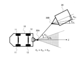
- FIG. 1 shows the vehicle equipped with the vehicle connection support system, and a trailer. It is a block diagram which shows the structure of the vehicle connection support system. It is a figure which shows the implementation range of the connection support by the 1st rudder angle control mode. It is a figure which shows the target rotation angle ⁇ E in the 2nd rudder angle control mode. It is a flowchart which shows the procedure of mode selection in 1st Embodiment of connection support control. It is a figure which shows various physical quantities including vehicle specification information used in connection support control. It is a flowchart which shows the processing procedure in the 1st rudder angle control mode in the 1st Embodiment.
- FIG. 1 is a configuration diagram of a vehicle 10 provided with a vehicle connection support system according to the present invention.
- the vehicle 10 in FIG. 1 is a four-wheeled vehicle provided with a pair of left and right front wheels 11 and 11 and a pair of left and right rear wheels 12 and 12, and is a towing vehicle that pulls a trailer 20 (towed vehicle).
- the trailer 20 is connected to the rear of the vehicle 10 by a coupler 30.
- the coupler 30 is composed of a first coupling portion 30A installed at the rear of the vehicle 10 and a second coupling portion 30B installed at the front of the trailer 20 and detachably connected to the first coupling portion 30A. By connecting the second connecting portion 30B to the first connecting portion 30A, the trailer 20 is connected to the vehicle 10.
- the coupler 30 is composed of, for example, a combination of a hitch ball as the first coupling portion 30A and a hitch coupler as the second coupling portion 30B.
- the vehicle 10 includes a front wheel steering device 13 that controls the steering angles ⁇ f of the front wheels 11 and 11, and a rear wheel steering device 14 that controls the steering angles ⁇ r of the rear wheels 12 and 12. That is, the vehicle 10 includes a four-wheel steering system including a front wheel steering device 13 and a rear wheel steering device 14.
- the front wheel steering device 13 includes a steering actuator such as a motor that generates steering force.
- the front wheel steering device 13 is a steering device that assists the driver in operating the steering wheel 13B by the steering actuator, and can automatically steer the front wheels 11 and 11 by the steering actuator.
- the front wheel steering device 13 includes a front wheel steering angle sensor 15 that detects the steering angles ⁇ f of the front wheels 11 and 11.
- the rear wheel steering device 14 is a steering device including a steering actuator such as a motor that generates a steering force, and the rear wheels 12 and 12 can be automatically steered by the steering actuator.
- the rear wheel steering device 14 includes a rear wheel steering angle sensor 16 that detects the steering angles ⁇ r of the rear wheels 12 and 12.
- the steering control device 40 is an electronic control device mainly composed of a microcomputer equipped with a processor, a memory, I / O, and a bus connecting these, and calculates based on various input information, and the steering angle as a calculation result.
- a control command is output to the front wheel steering device 13 and the rear wheel steering device 14.
- the steering control device 40 realizes a steering control function by executing a control program stored in a memory, and includes a function of supporting the connection between the vehicle 10 and the trailer 20 by four-wheel steering control as the steering control function. That is, the steering control device 40 constitutes a vehicle connection support device that supports the connection between the vehicle 10 and the trailer 20, and also has a function as a steering control unit in the vehicle connection support device.
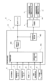
- FIG. 2 is a block diagram of a vehicle connection support system 50 including a front wheel steering device 13, a rear wheel steering device 14, and a steering control device 40.
- the steering control device 40 acquires detection signals of various detectors included in the vehicle 10.
- the vehicle 10 includes the front wheel steering angle sensor 15 and the rear wheel steering angle sensor 16 described above, an outside world recognition unit 61 that acquires outside world information of the vehicle 10, and a vehicle speed sensor 62 that detects the traveling speed of the vehicle 10.
- a manual steering detection unit 63 for detecting the presence or absence of manual steering by the driver, front and rear wheel fail detection units 64 for detecting the fail-safe state of the front wheels 11 and 11 and the rear wheels 12 and 12 are provided.
- the outside world recognition unit 61 is composed of, for example, a camera that photographs the rear of the vehicle 10 and an image processing device that processes an image captured by the camera.
- the front / rear wheel fail-safe state detected by the front / rear wheel fail detection unit 64 means that the movement of the wheels does not follow the steering angle control command given to the front wheel steering device 13 and the rear wheel steering device 14, but is a steering angle control command. It is a state in which the steering angle is fixed at an angle different from the corresponding steering angle.
- the front / rear wheel fail detection unit 64 includes, for example, steering angle information detected by the front wheel steering angle sensor 15 and the rear wheel steering angle sensor 16, and steering angle control commands given to the front wheel steering device 13 and the rear wheel steering device 14. By comparing, it is judged whether or not there is a fail-safe state in the front and rear wheels.
- the steering control device 40 determines whether or not the vehicle 10 can be connected to the trailer 20 by the information processing unit 40A that processes the detection signals of the various detectors and the vehicle connection support by the four-wheel steering control.
- the unit 40B has a target steering amount calculation unit 40C for calculating a target steering amount (steering angle control command) of the front and rear wheels for supporting connection.
- the information processing unit 40A processes the detection signals of various detectors using the vehicle specification information stored in the memory.
- the actuator control unit 41 acquires a signal relating to the target steering amount of the front and rear wheels calculated by the target steering amount calculation unit 40C of the steering control device 40 as a steering control command. Then, the actuator control unit 41 controls the steering actuator 13A of the front wheel steering device 13 and also controls the steering actuator 14A of the rear wheel steering device 14. Further, the HMI device 42 mounted on the vehicle 10 is a human-machine interface provided with a liquid crystal display, a lamp, and the like, and notifies the driver (occupant) of the vehicle 10 of information regarding the determination result in the connection possibility determination unit 40B. ..
- the HMI device 42 corresponds to a notification unit for notifying the driver of information regarding connection availability, and the steering control device 40 (steering control unit) is a command for notifying the driver that connection is not possible. Is output to the HMI device 42.
- connection support control by the steering control device 40 (in other words, connection support by automatic control of the steering angles of the front and rear wheels) will be described.
- the connection support control by the steering control device 40 is started, for example, when the driver of the vehicle 10 performs an operation instructing the activation of the connection support control.
- the steering control device 40 makes the steering angles ⁇ f of the front wheels 11 and 11 and the steering angles ⁇ r of the rear wheels 12 and 12 the same according to the physical quantity regarding the angle of the second connecting portion 30B with respect to the first connecting portion 30A. Select either the first steering angle control mode that controls the steering angle or the second steering angle control mode that controls the steering angles ⁇ f of the front wheels 11 and 11 and the steering angles ⁇ r of the rear wheels 12 and 12 to different steering angles. Then, a steering angle control command for controlling the front wheel steering device 13 and the rear wheel steering device 14 in the selected steering angle control mode is output.
- the steering control device 40 selects the first steering angle control mode when the angle of the second connecting portion 30B with respect to the first connecting portion 30A is smaller than a predetermined value, and the second connecting portion 30B with respect to the first connecting portion 30A. When the angle of is larger than the predetermined value, the second steering angle control mode is selected.
- the first steering angle control mode is a mode in which the steering direction of the front wheels 11 and 11 and the steering direction of the rear wheels 12 and 12 are the same, and the absolute value of the steering angle ⁇ f of the front wheels 11 and 11 and the rear wheel 12 , 12
- the absolute value of the steering angle ⁇ f is the same mode in the control command.
- the steering angles ⁇ f and ⁇ r [deg] are represented by, for example, a steering angle from neutral to the right with a positive angle and a steering angle from neutral to the left with a negative angle. Therefore, the state where the steering angles ⁇ f and ⁇ r are the same is the steering state in the first steering angle control mode in which the steering directions are the same and the steering angles are the same.
- the vehicle 10 moves substantially in parallel in the lateral direction.
- the steering control device 40 controls the front wheel steering device 13 and the rear wheel steering device 14 according to the second steering angle control mode, the vehicle 10 moves while rotating.
- the steering angle error due to the influence of the self-aligning torque (SAT), the lateral force, etc. is smaller than that when the vehicle 10 is translated, so the steering angle command for connection support is set high. It can be achieved with high accuracy, and the accuracy of connection support is improved.
- SAT self-aligning torque
- FIG. 3 is a diagram for explaining a steering angle control mode selection process in the connection support control, and is a diagram for explaining an angle of the second connection portion 30B with respect to the first connection portion 30A, in other words, a first connection portion 30A. 2
- the case where the relative position of the connecting portion 30B corresponds to the selection area of the first steering angle control mode (parallel movement mode) is shown.
- FIG. 3 shows a second connecting portion in a Cartesian coordinate system in which the front-rear direction of the vehicle 10 is the Z axis, the left-right direction of the vehicle 10 is the U axis, and the position of the first connecting portion 30A of the vehicle 10 is the origin (reference position).
- the position of 30B is indicated by coordinates (z, u).
- the coordinates (z, u) correspond to physical quantities related to the angle of the second connecting portion 30B with respect to the first connecting portion 30A.
- the coordinates (z, u) correspond to the target position in the connection support, and are also physical quantities related to the angle of the reference position of the vehicle with respect to the target position.
- the first steering angle control mode the state in which the second connecting portion 30B is located on the locus of the first connecting portion 30A when the steering angles of the front and rear wheels are set to the maximum and translated. It is the limit that can be connected by parallel movement in the rudder angle control mode. Then, if the region is closer to the Z axis than the locus, in other words, the angle of the second connecting portion 30B with respect to the first connecting portion 30A is smaller, the first steering angle control within the variable steering angle range.
- the first connecting portion 30A can be displaced and connected to the second connecting portion 30B.
- the maximum steering angle of the front and rear wheels in the first steering angle control mode is the maximum turning angle ⁇ fmax (maximum steering angle) of the front wheels 11 and 11.
- the maximum turning angle ⁇ rmax (maximum steering angle) of the rear wheels 12 and 12 whichever is smaller as the absolute value, becomes the maximum turning angle ⁇ max.
- the maximum turning angle ⁇ rmax of the rear wheels 12 and 12 is smaller than the maximum turning angle ⁇ fmax of the front wheels 11 and 11, so that the maximum steering angle ⁇ max of the front and rear wheels in the first steering angle control mode is the rear wheels 12 and 12.
- the maximum turning angle ⁇ rmax is obtained, and the connectable region in the first steering angle control mode is determined based on the maximum turning angle ⁇ rmax of the rear wheels 12 and 12.
- the steering control device 40 is set based on the maximum steering angle ⁇ max of the front and rear wheels in the first steering angle control mode, and is set by the upper limit steering angle ⁇ p (upper steering angle ⁇ p ⁇ ) that can be connected by translation in the first steering angle control mode. ⁇ max) is stored in the memory. Then, when the angle of the second connecting portion 30B with respect to the first connecting portion 30A is the upper limit steering angle ⁇ p or is smaller than the upper limit steering angle ⁇ p, the steering control device 40 is translated by the first steering angle control mode. Judge that it can be connected.
- the steering control device 40 determines that the second connecting portion 30B can be connected by translation in the first steering angle control mode.
- the steering control device 40 when the coordinate value (z, u) indicating the position of the second connecting portion 30B satisfies Equation 2, in other words, the coordinate value (z, u) is within the connectable range by translation. At the time, the first steering angle control mode is selected. Then, the steering control device 40 uses the front wheel steering device 13 and the rear wheel steering device as steering angle control commands for controlling the four-wheel steering in the first steering angle control mode for the command steering angles ⁇ f * and ⁇ r * obtained by Equation 1. Output to 14.
- the steering control device 40 when the coordinate value (z, u) indicating the position of the second connecting portion 30B does not satisfy Equation 2, in other words, the coordinate value (z, u) is a connectable range due to translation. If it deviates from, the second steering angle control mode is selected. Then, the steering control device 40 issues a steering angle control command for controlling in the second steering angle control mode so that the coordinate values (z, u) indicating the position of the second connecting portion 30B satisfy the equation 2. The obtained steering angle control command is output to the front wheel steering device 13 and the rear wheel steering device 14.
- FIG. 4 shows the correlation between the target rotation angle ⁇ E when the vehicle 10 is rotated by the second steering angle control mode and the angle ⁇ p that defines the range that can be connected by translation.
- the target rotation angle ⁇ E can be obtained by the mathematical formula 3.
- the steering control device 40 performs steering control in the second steering angle control mode to obtain an angle ⁇ p.
- the second steering angle control mode is switched to the first steering angle control mode, the vehicle 10 is translated, and the first connecting portion 30A is moved to the first position. 2 Move to the position of the connecting portion 30B. If the first connecting portion 30A is moved to the connecting position by parallel movement in the first steering angle control mode, the influence of self-aligning torque and lateral force is suppressed, and the error of the wheel movement with respect to the steering angle command. Can be made smaller, and the accuracy of the connection support leading to the connection position is improved.
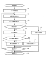
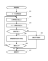
- FIG. 5 is a flowchart showing a steering angle control mode selection process in the first embodiment of connection support control by the steering control device 40.
- the first steering angle control mode is a steering angle control mode (in other words, a translation mode) in which the steering angles ⁇ f of the front wheels 11 and 11 and the steering angles ⁇ r of the rear wheels 12 and 12 are controlled to the same steering angle.
- the second steering angle control mode is a steering angle control mode (in other words, a rotational movement mode) in which the steering angles ⁇ f of the front wheels 11 and 11 and the steering angles ⁇ r of the rear wheels 12 and 12 are controlled to different steering angles. is there.
- step S102 the steering control device 40 reads vehicle information which is information on the behavior of the own vehicle.
- the vehicle information includes information on the speed V of the rear wheels 12 and 12, the steering angles ⁇ f, ⁇ r, and the like.
- step S103 the steering control device 40 reads information regarding the positional relationship between the first connecting portion 30A and the second connecting portion 30B from the outside world recognition unit 61.
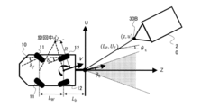
- the information regarding the positional relationship between the first connecting portion 30A and the second connecting portion 30B includes the information regarding the first connecting portion 30A and the second connecting portion 30B in the Z-axis direction, which is the front-rear direction of the vehicle 10, as shown in FIG.
- the coordinate value z indicating the distance, the coordinate value u indicating the distance between the first connecting portion 30A and the second connecting portion 30B in the U-axis direction which is the left-right direction of the vehicle 10, the yaw angle ⁇ of the trailer 20 and the like are included.
- Lw is the wheel base length of the vehicle 10
- Lb is the distance from the center of the rear wheel shaft to the first connecting portion 30A
- R is the turning radius of the vehicle 10
- Vb is the speed of the first connecting portion 30A
- ⁇ b is the slip angle of the first connecting portion 30A, which is the angle formed by the velocity vector of the first connecting portion 30A and the Z axis.
- the yaw angle ⁇ of the trailer 20 is an angle formed by the Z-axis in the front-rear direction of the vehicle 10 and the front-rear direction of the trailer 20, and is a physical quantity relating to the relative yaw angle of the trailer 20 with respect to the vehicle 10.
- the vehicle 10 is not limited to the system provided with the outside world recognition unit 61, and the outside world recognition unit 61 equipped with a camera or the like can be installed at a place other than the vehicle 10.
- a camera constituting the outside world recognition unit 61 is attached to a fixed object such as a garage, a building, or a road lighting around a place where the vehicle 10 and the trailer 20 are connected, and the outside world information acquired by the camera is used.
- the system can be received by the steering control device 40 wirelessly.
- the outside world recognition can be performed by using both the camera installed in the vehicle 10 and the camera installed in the fixed object, and a plurality of cameras can be installed in the vehicle 10 and / or the fixed object. ..
- the steering control device 40 connects the first connecting portion 30A and the second connecting portion 30B by four-wheel steering control based on the coordinates (z, u) of the second connecting portion 30B in step S104 (connectability determination unit). Determine if you can.
- the steering control device 40 determines that the connection is possible.
- the maximum displacement amount Umax described above advances by the relative distance between the first connecting portion 30A and the second connecting portion 30B in the Z-axis direction when the first connecting portion 30A advances by the coordinate value z in the Z-axis direction. This is the maximum amount of displacement in the U-axis direction.
- the steering control device 40 calculates the maximum displacement amount Umax according to Equation 4.
- ⁇ max is the maximum slip angle of the first connecting portion 30A
- Rmin is the minimum turning radius of the first connecting portion 30A.
- the steering angle ⁇ f of the front wheels 11 and 11 is set as the maximum turning angle
- the steering angle ⁇ r of the rear wheels 12 and 12 is set as the maximum turning angle in the direction opposite to the front wheels 11 and 11.
- the steering control device 40 sets the steering angle ⁇ f of the front wheels 11 and 11 as the maximum turning angle, and sets the steering angle ⁇ r of the rear wheels 12 and 12 in the opposite direction to the front wheels 11 and 11.
- the steering control device 40 determines that the first connecting portion 30A can be connected to the second connecting portion 30B when
- the steering angle ⁇ f of the front wheels 11 and 11 is set as the maximum turning angle
- the steering angle ⁇ r of the rear wheels 12 and 12 is set as the maximum turning angle in the direction opposite to the front wheels 11 and 11.
- the first connecting portion 30A cannot be displaced to the position of the second connecting portion 30B. Therefore, when
- the maximum slip angle ⁇ max is large, the minimum turning radius Rmin is small, and the maximum displacement amount Umax is large as compared with the front wheel steering vehicle, so that the connectable range by steering control is widened. .. Then, since the steering control device 40 determines whether or not the connection is possible with the maximum displacement amount Umax of the vehicle 10 equipped with the four-wheel steering system as the limit value at extremely low speed, it is possible to support the connection in the widest possible range. Is.
- the steering control device 40 When
- the upper limit steering angle used for determining the transition from the first steering angle control mode to the second steering angle control mode rather than the upper limit steering angle ⁇ DLM used for determining the transition from the second steering angle control mode to the first steering angle control mode.
- the ⁇ ULM is increased so that the rudder angle control mode switching judgment has hysteresis.
- hunting between the first steering angle control mode and the second steering angle control mode can be suppressed, and the steering control becomes unstable near the upper limit steering angle ⁇ p. Can be suppressed.
- step S106 the steering control device 40 determines whether or not the first connecting portion 30A can be connected to the second connecting portion 30B by translation in the first steering angle control mode. That is, the steering control device 40 is based on the upper limit steering angle ⁇ p set in step S105 and the information of the coordinate values (z, u) indicating the position of the second connecting portion 30B acquired from the outside world recognition unit 61. Judge whether or not the relationship is satisfied. Then, when the relationship of the equation 2 is satisfied and the connection is within the range where the connection by the parallel movement is possible, the steering control device 40 changes the first connection portion 30A to the second connection portion 30B by the parallel movement in the first steering angle control mode. It is determined that they can be connected, and the process proceeds to step S107 (target steering amount calculation unit).
- the steering control device 40 rotates the vehicle 10 in the second steering angle control mode to bring the vehicle into the connectable range in the first steering angle control mode. It is determined that it is necessary to move 10, and the process proceeds to step S111 (target steering amount calculation unit). In other words, the steering control device 40 selects the first steering angle control mode and proceeds to step S107 when it falls within the range where the connection by the parallel movement is possible, and when it is not within the range where the connection by the parallel movement is possible. The second steering angle control mode is selected and the process proceeds to step S111.
- step S107 the steering control device 40 calculates a steering angle control command for the front and rear wheels for control in the first steering angle control mode.
- the processing content in step S107 will be described in detail later according to the flowchart of FIG.
- step S111 the steering control device 40 calculates a steering angle control command for the front and rear wheels for control in the second steering angle control mode.
- the processing content in step S111 will be described in detail later according to the flowchart of FIG.
- step S108 the steering control device 40 determines whether or not the connection between the first connecting portion 30A and the second connecting portion 30B is completed. For example, in the steering control device 40, when the position z of the second connecting portion 30B in the Z-axis direction satisfies z ⁇ 0, in other words, the position of the first connecting portion 30A is displaced to the position of the second connecting portion 30B. When it is detected, it is judged that the connection is completed.
- step S109 when the steering control device 40 determines that the connection is completed, the connection support control by the four-wheel steering is terminated in step S109. On the other hand, when the steering control device 40 determines that the connection is not completed, it returns to step S102 and continues the connection support control by automatically controlling the steering angles of the front and rear wheels.
- step S104 determines in step S104 that the second connecting portion 30B cannot be connected to the first connecting portion 30A by the four-wheel steering control (cannot be connected)
- the steering control device 40 proceeds to step S110.
- step S110 the steering control device 40 outputs a command to the HMI device 42 notifying the driver that the connection is not possible due to the current positional relationship between the vehicle 10 and the trailer 20.
- the HMI device 42 Based on the command, the HMI device 42 notifies the driver by displaying a warning message, lighting a lamp, or the like that the connection cannot be achieved by the connection support by the four-wheel steering control.
- the HMI device 42 notifies the driver that the vehicle cannot be connected, and also notifies the driver of advice on driving operations for enabling the connection, such as the need to move the vehicle 10 further away from the trailer 20 in order to enable the connection. can do.
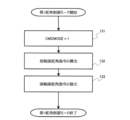
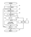
- step S107 of FIG. 5 the processing content in step S107 of FIG. 5 will be described in detail based on the flowchart of FIG. 7. Since the steering control device 40 provides connection support by four-wheel steering control in the first steering angle control mode, the variable CMDMODE is set to "1" in step S131.
- step S132 the steering control device 40 sets the front wheel command steering angle ⁇ f * (front wheel steering angle control command) according to Equation 6 based on the coordinate values (z, u) indicating the position information of the second connecting portion 30B.
- the obtained front wheel command steering angle ⁇ f * is output to the actuator control unit 41.
- the wheel command steering angle ⁇ r * is output to the actuator control unit 41.
- the vehicle 10 does not rotate, so that the lateral force of the tire is not constantly generated.
- the influence of disturbances related to steering can be significantly reduced, and the error of wheel movement with respect to the steering angle command can be reduced, so that the connection accuracy is improved. improves.
- step S111 of FIG. 5 the processing content in step S111 of FIG. 5 will be described in detail based on the flowchart of FIG. Since the steering control device 40 provides connection support by four-wheel steering control in the second steering angle control mode, the variable CMDMODE is set to "2" in step S141.
- step S142 the steering control device 40 calculates the target rotation angle ⁇ E (see FIG. 4) in the second steering angle control mode according to Equation 7.
- the target rotation angle ⁇ E is a target rotation angle required for four-wheel steering control in the second steering angle control mode in order to enable connection by translation in the first steering angle control mode.
- the coordinate value u in Equation 7 may be a positive value or a negative value, while ⁇ p is a positive constant value set based on Equation 5, so that the signs of the angles are matched.
- is provided in.
- FIG. 9 is a diagram for explaining one aspect of the calculation method of the steering angle control command in the second steering angle control mode in step S143.
- the steering control device 40 is the coordinate value which is the current position of the first connecting portion 30A when the first connecting portion 30A advances by the forward gaze distance LP in the Z-axis direction from the coordinate value (0,0) which is the current position.
- the target lateral movement amount UE in the U-axis direction required to position the first connecting portion 30A on the line connecting (0,0) and the coordinate value (z, u) indicating the position of the second connecting portion 30B is determined.
- the forward gaze distance LP is a positive predetermined value (LP> 0 m), and is, for example, about 0.5 to 1.0 m, which is the mileage when the vehicle 10 travels for 1 second at the average traveling speed at the time of connection. Can be done.
- the steering control device 40 has the front wheel command steering angle ⁇ f * and the front wheel command steering angle ⁇ f * in the second steering angle control mode based on the target lateral movement amount UE obtained according to Equation 8 and the target rotation angle ⁇ E obtained in step S142.
- the rear wheel command steering angle ⁇ r * is calculated, and the calculated steering angle control command is output to the actuator control unit 41.
- the front wheel command steering angle ⁇ f * and the rear wheel command steering angle ⁇ r * are set to different steering angles in order to realize the target rotation angle ⁇ E.
- the steering control device 40 shifts from the second steering angle control mode to the first steering angle control mode and is in the parallel movement state.
- the first connecting portion 30A is connected to the second connecting portion 30B.
- connection support can be performed with high accuracy even though it is a simple calculation process. That is, when the positional relationship between the vehicle 10 and the trailer 20 is within a range in which they can be connected by translation, the steering control device 40 performs steering control based on the first steering angle control mode to perform self-alignment. The influence of disturbances such as torque and lateral force can be reduced, and the connection accuracy is improved. Further, when the positional relationship between the vehicle 10 and the trailer 20 is not within a range that can be connected by translation, the steering control device 40 performs steering control based on the second steering angle control mode to support the connection. The range that can be implemented can be expanded.
- FIG. 10 is a flowchart showing a steering angle control mode selection process according to the second embodiment.
- step S201-step S205 of the flowchart of FIG. 10 the steering control device 40 performs the same processing as step S101-step S105 of the flowchart of FIG. 5, so detailed description thereof will be omitted.
- step S206 the steering control device 40 can connect the first connecting portion 30A to the second connecting portion 30B by translation in the first steering angle control mode, and the vehicle 10 and the trailer at the time of translation in parallel movement. Whether or not the 20 is substantially in line is determined based on the information acquired from the outside world recognition unit 61.
- step S206 the steering control device 40 satisfies the relationship of Equation 2 and whether the absolute value of the yaw angle ⁇ (see FIG. 6) of the trailer 20 is the permissible angle ⁇ tlr ( ⁇ tlr> 0deg) or from the permissible angle ⁇ tlr. It is also small and it is judged whether the relation of the formula 9 is satisfied.
- the yaw angle ⁇ of the trailer 20 at the start of the parallel movement becomes the yaw angle ⁇ at the time of connection as it is. Therefore, determining whether or not the yaw angle ⁇ of the trailer 20 is equal to or less than the allowable angle ⁇ tlr determines whether or not the vehicle 10 and the trailer 20 are substantially aligned at the time of connection.
- the permissible angle ⁇ tlr is set to about 5 deg, for example, based on the angle (resolution) at which the outside world recognition unit 61 can secure the recognition accuracy.
- step S211 selects the second steering angle control mode to steer. Obtain the angle control command.
- step S208-step S210 of the flowchart of FIG. 10 the steering control device 40 performs the same processing as step S108-step S110 of the flowchart of FIG. 5, so detailed description thereof will be omitted.
- the selection condition of the first steering angle control mode is that the vehicle 10 and the trailer 20 are substantially aligned at the time of connection. Therefore, for example, the vehicle is placed in a parking frame (parking space).
- a parking frame parking space
- the vehicle 10 is connected to the trailer 20, it is possible to prevent the vehicle 10 from protruding from the parking frame, and it is possible to obtain an effect that the driving operation at the start of running after the connection is facilitated.
- step S231 the steering control device 40 sets the variable CMDMODE to "1".
- step S232 the steering control device 40 sets the front wheel command steering angle ⁇ f * (front wheel steering angle control command) according to Equation 6 based on the coordinate values (z, u) indicating the position information of the second connecting portion 30B.
- the obtained front wheel command steering angle ⁇ f * is output to the actuator control unit 41.
- the wheel command steering angle ⁇ r * is output to the actuator control unit 41.
- a condition for obtaining a steering angle control command in the first steering angle control mode in step S207 a condition that the vehicle 10 and the trailer 20 are substantially aligned when connected in parallel movement is added.
- the vehicle 10 and the trailer 20 are connected at the time of connection. It becomes almost a straight line.
- step S241 the steering control device 40 sets the variable CMDMODE to "2".
- step S242 the steering control device 40 determines whether or not the first connecting portion 30A is within the range in which the first connecting portion 30A can move to the second connecting portion 30B by the parallel movement of the vehicle 10 whether or not the equation 2 is satisfied. Judge based on.
- the four-wheel steering control by the first steering angle control mode is performed when the condition that the vehicle 10 and the trailer 20 are substantially aligned at the time of connection can be satisfied by translation. Therefore, although the vehicle can be connected by translation, the process of step S211 proceeds even when the vehicle 10 and the trailer 20 are not substantially aligned at the time of connection. Therefore, in step S242, the steering control device 40 again determines whether or not the connection can be made by parallel movement.
- step S243 the steering control device 40 sets zero to the target rotation angle ⁇ E1 (see FIG. 13) for making the vehicle 10 connectable by translation.
- the steering control device 40 has a target rotation angle in step S243.
- Set ⁇ E1 0deg.
- the process proceeds to step S244, and the target rotation angle ⁇ E1 of the vehicle 10 for making the vehicle 10 connectable by translation is calculated according to the above-mentioned mathematical formula 7.
- step S245 the steering control device 40 determines whether or not the absolute value of the yaw angle ⁇ of the trailer 20 is equal to or less than the allowable angle ⁇ tlr (whether or not the equation 9 is satisfied). Then, when the absolute value of the yaw angle ⁇ of the trailer 20 is the permissible angle ⁇ tlr or smaller than the permissible angle ⁇ tlr, the steering control device 40 proceeds to step S246, and the vehicle 10 and the trailer 20 are substantially aligned at the time of connection. Set zero to the target rotation angle ⁇ E2 (see FIG. 13).
- the steering control device 40 proceeds to step S247 and sets the absolute value of the yaw angle ⁇ of the trailer 20 to the permissible angle ⁇ tlr according to the equation 10.
- is for matching the sign of the angle.
- step S248 the steering control device 40 connects the final target rotation angle ⁇ E in the second steering angle control mode with the target rotation angle ⁇ E1 for making the final target rotation angle ⁇ E connectable by translation, and the vehicle 10 at the time of connection. It is calculated according to Equation 11 based on the target rotation angle ⁇ E2 for aligning the trailer 20 with the trailer 20.
- step S249 the steering control device 40 controls the second steering angle based on the target lateral movement amount UE obtained according to the above equation 8 and the target rotation angle ⁇ E obtained in step S248, as in step S143.
- the front wheel command steering angle ⁇ f * and the rear wheel command steering angle ⁇ r * in the mode are calculated, and the calculated steering angle control command is output to the actuator control unit 41.
- the steering control device 40 controls the steering angles of the front and rear wheels in the first steering angle control mode when the vehicle 10 and the trailer 20 can be connected in a substantially straight line by translation.
- the steering control device 40 has a target rotation angle ⁇ E1 for making the vehicle 10 connectable by translation, and the vehicle 10 at the time of connection.
- the steering angles of the front and rear wheels are controlled in the second steering angle control mode based on the target rotation angle ⁇ E2 for aligning the trailer 20 with the trailer 20. Therefore, the influence of disturbances such as self-aligning torque and lateral force can be suppressed to improve the accuracy of the connection support, and the vehicle 10 and the trailer 20 can be substantially aligned at the time of connection.
- the flowchart of FIG. 14 shows the automatic rear wheel steering angle for connection support when the steering angles of the front wheels 11 and 11 are controlled manually by the driver (when the manual steering detection unit 63 detects manual steering). Shows control.
- the steering control device 40 performs the same processing as step S101-step S104 of the flowchart of FIG. 5, so detailed description thereof will be omitted.
- step S304 connectability determining unit of the steering control device 40.
- Umax maximum displacement amount calculated according to the equation 4 in step S304 (connectability determining unit) of the steering control device 40.
- step S305 target steering amount calculation unit.
- the steering control device 40 calculates the steering angle control commands of the rear wheels 12 and 12 as connection support so as to compensate for the excess or deficiency of the front wheel steering angles controlled by the driver.
- the steering control device 40 obtains the target lateral movement amount UE and the target rotation angle ⁇ E for directing the first connecting portion 30A toward the second connecting portion 30B, and the front wheel steering angle (front wheel steering) controlled by the driver.
- the value detected by the angle sensor 15) is assumed to be the front wheel command steering angle ⁇ f *, and when the front wheel command steering angle ⁇ f *, the rear wheel command steering angle ⁇ r * that can realize the target lateral movement amount UE and the target rotation angle ⁇ E is set. Calculate (see FIG. 9). Then, the steering control device 40 outputs the calculated signal of the rear wheel command steering angle ⁇ r * to the actuator control unit 41, and automatically controls the steering angles of the rear wheels 12 and 12 to the rear wheel command steering angle ⁇ r *.
- step S306-step S308 the steering control device 40 performs the same processing as in step S108-step S110 of the flowchart of FIG. 5, and therefore detailed description thereof will be omitted.
- the steering control device 40 when the driver controls the steering angles of the front wheels 11 and 11, even if the driver causes an excess or deficiency of the front wheel steering angles, the rear wheels are compensated for the excess or deficiency. Since the steering angle is controlled, highly accurate connection support can be realized.
- the fail-safe state is an abnormal state in which the wheel movement does not comply with the steering angle command (steering angle control command) and the steering angle is fixed.
- the flowchart of FIG. 15 shows the front and rear wheel steering angles for connection support, which is executed when the front and rear wheel fail detection unit 64 detects that the front wheels 11, 11 or the rear wheels 12, 12 are in the fail-safe state. Indicates automatic control.
- the steering control device 40 is in the above-described first embodiment or As in the second embodiment, the steering angles of the front and rear wheels are automatically controlled to support the connection.
- step S401-step S403 of FIG. 15 the steering control device 40 performs the same processing as step S101-step S103 of the flowchart of FIG. 5, and therefore detailed description thereof will be omitted.
- step S404 connectability determination unit
- the steering control device 40 compares the coordinate value u of the U axis of the second connecting unit 30B with the maximum displacement amount Umax in the same manner as in step S104, and connects by four-wheel steering. It is determined whether or not the second connecting portion 30B can be connected to the first connecting portion 30A by the support control.
- the steering control device 40 responds to the fixed steering angle (fail-safe steering angle) of the wheels in the fail-safe state. Change the maximum displacement Umax. For example, when the front wheels 11 and 11 are in the fail-safe state, the steering control device 40 sets the maximum slip angle ⁇ max and the minimum turning radius Rmin as the current fixed steering angle ⁇ f of the front wheels 11 and 11. It is obtained as a value when the steering angles ⁇ r of the rear wheels 12 and 12 are set to the maximum turning angle in the direction opposite to the front wheels 11 and 11.
- the steering control device 40 obtains the maximum displacement amount Ufalemax based on the maximum slip angle ⁇ max and the minimum turning radius Rmin in the fail-safe state, and the absolute value of the coordinate value u indicating the position of the second connecting portion 30B is the maximum displacement amount.
- Ufalemax the absolute value of Ufalemax (
- step S404 the steering control device 40 proceeds to step S405 (target steering amount calculation unit) and calculates a steering angle control command.
- the steering control device 40 is a wheel steering capable of steering control so that the first connecting portion 30A faces the second connecting portion 30B under the condition that the steering angle of one of the front and rear wheels is fixed in step S405. Calculate the angle control command.
- the steering control device 40 obtains the target lateral movement amount UE and the target rotation angle ⁇ E for directing the first connecting portion 30A toward the second connecting portion 30B.
- the fixed steering angles of the front wheels 11 and 11 are set as the front wheel command steering angle ⁇ f *, and when the front wheel command steering angle ⁇ f *, the target lateral movement amount UE and the target rotation angle ⁇ E can be realized.
- Calculate the angle ⁇ r * (see FIG. 9).
- step S406-step S408 of FIG. 15 the steering control device 40 performs the same processing as step S108-step S110 of the flowchart of FIG.
- the connection can be supported by controlling the steering angle of the other wheel. Since the steering angle is controlled, the situation where the connection support can be performed can be expanded and the convenience is improved.
- the driver can select whether or not the implementation condition of the first steering angle control mode is that the vehicle 10 and the trailer 20 are substantially aligned at the time of connection.
- the allowable angle ⁇ tlr can be configured to be arbitrarily changed by the driver.
- a condition of a distance between the first connecting portion 30A and the second connecting portion 30B is added, and the steering control device 40 may be, for example, with the first connecting portion 30A. After the distance to the second connecting portion 30B falls below the threshold value, the transition from the second steering angle control mode to the first steering angle control mode can be performed. Further, when the steering control device 40 determines that the connection is not possible, the steering control device 40 notifies the driver of information such as the movement direction and the movement distance of the vehicle 10 for enabling the connection via the HMI device 42, or the vehicle 10 It is possible to notify the driver via the HMI device 42 that the vehicle has moved within the connectable range.
- the traveling speed of the vehicle 10 becomes excessively high during steering control for connection support (for example, during selection of the first steering angle control mode), and the accuracy of connection support control decreases. It is possible to set a limiter for the traveling speed so that the limiter is not exceeded, and output a control command for the control driving force so as not to exceed this limiter.
- the present invention is not limited to the above-described embodiment, and includes various modifications.
- the above-described embodiment has been described in detail in order to explain the present invention in an easy-to-understand manner, and is not necessarily limited to the one including all the described configurations.
- it is possible to replace a part of the configuration of one embodiment with the configuration of another embodiment and it is also possible to add the configuration of another embodiment to the configuration of one embodiment.
Landscapes
- Engineering & Computer Science (AREA)
- Transportation (AREA)
- Mechanical Engineering (AREA)
- Chemical & Material Sciences (AREA)
- Combustion & Propulsion (AREA)
- Physics & Mathematics (AREA)
- Mathematical Physics (AREA)
- Theoretical Computer Science (AREA)
- Steering Control In Accordance With Driving Conditions (AREA)
- Steering-Linkage Mechanisms And Four-Wheel Steering (AREA)
Abstract
車両連結支援装置は、車両の第1連結部に対するトレーラの第2連結部の角度に関する物理量に応じて、前記車両の前輪の操舵角と前記車両の後輪の操舵角を同じ操舵角に制御する第1舵角制御モードと、前記前輪の操舵角と前記後輪の操舵角を異なる操舵角に制御する第2舵角制御モードと、のいずれかを舵角制御モードとして選択し、選択された前記舵角制御モードで制御するための舵角制御指令を前記車両の前輪操舵装置及び後輪操舵装置に出力する。
Description
本発明は、車両とトレーラとの連結を操舵角の自動制御によって支援する、車両連結支援装置、車両連結支援方法、車両連結支援システム、及び操舵制御装置に関する。
特許文献1には、牽引車両と被牽引車両とを連結するための自動連結システムが開示されている。
前記自動連結システムは、被牽引車両の連結部に設けた複数の検出ターゲットを検出する検出器と、コントローラと、前輪を自動操舵する自動操舵システムと、自動ブレーキシステムとを有する。
そして、コントローラは、複数の検出ターゲットの検出結果に基づいて牽引車両に対する被牽引車両の位置を求め、牽引車両と被牽引車両との連結をアシストするように、自動操舵システム及び自動ブレーキシステムを作動させる。
前記自動連結システムは、被牽引車両の連結部に設けた複数の検出ターゲットを検出する検出器と、コントローラと、前輪を自動操舵する自動操舵システムと、自動ブレーキシステムとを有する。
そして、コントローラは、複数の検出ターゲットの検出結果に基づいて牽引車両に対する被牽引車両の位置を求め、牽引車両と被牽引車両との連結をアシストするように、自動操舵システム及び自動ブレーキシステムを作動させる。
ところで、被牽引車両(トレーラ)と牽引車両との位置関係に基づき牽引車両の前輪を自動操舵する連結支援システムの場合、牽引車両の旋回によって生じるセルフアライニングトルク(SAT)や横力などの影響によって、操舵角指令に対する車輪の動きの誤差が大きくなり易く、連結支援の精度が低下するおそれがあった。
本発明は、上記実情に鑑みてなされたものであり、その目的は、自動操舵制御による連結支援の精度を向上させることができる、車両連結支援装置、車両連結支援方法、車両連結支援システム、及び操舵制御装置を提供することにある。
本発明によれば、その1つの態様において、車両の第1連結部に対するトレーラの第2連結部の角度に関する物理量に応じて、前記車両の前輪の操舵角と前記車両の後輪の操舵角を同じ操舵角に制御する第1舵角制御モードと、前記前輪の操舵角と前記後輪の操舵角を異なる操舵角に制御する第2舵角制御モードと、のいずれかを舵角制御モードとして選択し、選択された前記舵角制御モードで制御するための舵角制御指令を前記車両の前輪操舵装置及び後輪操舵装置に出力する。
本発明の一実施形態によれば、自動操舵制御による連結支援の精度を向上させることができる。
以下、本発明に係る車両連結支援装置、車両連結支援方法、車両連結支援システム、及び操舵制御装置の実施形態を、図面に基づいて説明する。
図1は、本発明に係る車両連結支援システムを備えた車両10の構成図である。
図1は、本発明に係る車両連結支援システムを備えた車両10の構成図である。
図1の車両10は、左右一対の前輪11,11、左右一対の後輪12,12を備えた4輪自動車であって、トレーラ20(被牽引車)を牽引する牽引車である。
トレーラ20は、連結器30によって車両10の後方に連結される。
トレーラ20は、連結器30によって車両10の後方に連結される。
連結器30は、車両10の後部に設置された第1連結部30Aと、トレーラ20の前部に設置され第1連結部30Aに係脱可能に連結する第2連結部30Bとで構成され、第1連結部30Aに第2連結部30Bを連結することで、車両10にトレーラ20が連結される。
連結器30は、例えば、第1連結部30Aとしてのヒッチボールと、第2連結部30Bとしてのヒッチカプラとの組み合わせからなる。
連結器30は、例えば、第1連結部30Aとしてのヒッチボールと、第2連結部30Bとしてのヒッチカプラとの組み合わせからなる。
車両10は、前輪11,11の操舵角δfを制御する前輪操舵装置13、及び、後輪12,12の操舵角δrを制御する後輪操舵装置14を備える。つまり、車両10は、前輪操舵装置13及び後輪操舵装置14からなる4輪操舵システムを備える。
前輪操舵装置13は、操舵力を発生するモータなどの操舵アクチュエータを備える。そして、前輪操舵装置13は、操舵アクチュエータによって運転者によるステアリングホイール13Bの操作を補助し、また、操舵アクチュエータによって前輪11,11の自動操舵が可能な操舵装置である。
前輪操舵装置13は、前輪11,11の操舵角δfを検出する前輪操舵角センサ15を備える。
前輪操舵装置13は、操舵力を発生するモータなどの操舵アクチュエータを備える。そして、前輪操舵装置13は、操舵アクチュエータによって運転者によるステアリングホイール13Bの操作を補助し、また、操舵アクチュエータによって前輪11,11の自動操舵が可能な操舵装置である。
前輪操舵装置13は、前輪11,11の操舵角δfを検出する前輪操舵角センサ15を備える。
後輪操舵装置14は、操舵力を発生するモータなどの操舵アクチュエータを備え、この操舵アクチュエータによって後輪12,12の自動操舵が可能な操舵装置である。
後輪操舵装置14は、後輪12,12の操舵角δrを検出する後輪操舵角センサ16を備える。
後輪操舵装置14は、後輪12,12の操舵角δrを検出する後輪操舵角センサ16を備える。
操舵制御装置40は、プロセッサ、メモリ、I/O、これらを接続するバスを備えるマイクロコンピュータを主体とする電子制御装置であって、入力した各種情報に基づいて演算し、演算結果としての舵角制御指令を前輪操舵装置13及び後輪操舵装置14に出力する。
操舵制御装置40は、メモリに記憶された制御プログラムを実行することによって操舵制御機能を実現し、操舵制御機能として、4輪操舵制御によって車両10とトレーラ20との連結を支援する機能を含む。
つまり、操舵制御装置40は、車両10とトレーラ20との連結を支援する車両連結支援装置を構成し、また、車両連結支援装置における操舵コントロール部としての機能を有する。
操舵制御装置40は、メモリに記憶された制御プログラムを実行することによって操舵制御機能を実現し、操舵制御機能として、4輪操舵制御によって車両10とトレーラ20との連結を支援する機能を含む。
つまり、操舵制御装置40は、車両10とトレーラ20との連結を支援する車両連結支援装置を構成し、また、車両連結支援装置における操舵コントロール部としての機能を有する。
図2は、前輪操舵装置13、後輪操舵装置14、及び操舵制御装置40を含む車両連結支援システム50の構成ブロック図である。
操舵制御装置40は、車両10が備える各種検出器の検出信号を取得する。
車両10は、各種検出器として、前述した前輪操舵角センサ15及び後輪操舵角センサ16の他、車両10の外界情報を取得する外界認識部61、車両10の走行速度を検出する車速センサ62、運転者による手動操舵の有無を検出する手動操舵検出部63、前輪11,11及び後輪12,12のフェールセーフ状態を検出する前後輪フェール検出部64などを備える。
操舵制御装置40は、車両10が備える各種検出器の検出信号を取得する。
車両10は、各種検出器として、前述した前輪操舵角センサ15及び後輪操舵角センサ16の他、車両10の外界情報を取得する外界認識部61、車両10の走行速度を検出する車速センサ62、運転者による手動操舵の有無を検出する手動操舵検出部63、前輪11,11及び後輪12,12のフェールセーフ状態を検出する前後輪フェール検出部64などを備える。
外界認識部61は、例えば、車両10の後方を撮影するカメラと、カメラが撮影した画像を処理する画像処理装置とで構成される。
前後輪フェール検出部64が検出する前後輪のフェールセーフ状態とは、車輪の動きが、前輪操舵装置13,後輪操舵装置14に与えられた舵角制御指令に従わず、舵角制御指令に応じた操舵角とは異なる角度に操舵角が固定される状態である。
前後輪フェール検出部64は、例えば、前輪操舵角センサ15及び後輪操舵角センサ16が検出した操舵角の情報と、前輪操舵装置13及び後輪操舵装置14に与えられた舵角制御指令とを比較することで、前後輪におけるフェールセーフ状態の有無を判断する。
前後輪フェール検出部64が検出する前後輪のフェールセーフ状態とは、車輪の動きが、前輪操舵装置13,後輪操舵装置14に与えられた舵角制御指令に従わず、舵角制御指令に応じた操舵角とは異なる角度に操舵角が固定される状態である。
前後輪フェール検出部64は、例えば、前輪操舵角センサ15及び後輪操舵角センサ16が検出した操舵角の情報と、前輪操舵装置13及び後輪操舵装置14に与えられた舵角制御指令とを比較することで、前後輪におけるフェールセーフ状態の有無を判断する。
操舵制御装置40は、上記の各種検出器の検出信号を処理する情報処理部40A、4輪操舵制御による車両連結支援によって車両10がトレーラ20と連結可能であるか否かを判断する連結可否判断部40B、連結を支援するための前後輪の目標操舵量(舵角制御指令)を算出する目標操舵量算出部40Cを有する。
なお、情報処理部40Aは、メモリに保存されている車両諸元情報を用いて各種検出器の検出信号を処理する。
なお、情報処理部40Aは、メモリに保存されている車両諸元情報を用いて各種検出器の検出信号を処理する。
アクチュエータ制御部41は、操舵制御装置40の目標操舵量算出部40Cが算出した前後輪の目標操舵量に関する信号を操舵制御指令として取得する。そして、アクチュエータ制御部41は、前輪操舵装置13の操舵アクチュエータ13Aを制御し、また、後輪操舵装置14の操舵アクチュエータ14Aを制御する。
また、車両10に搭載されるHMIデバイス42は、液晶ディスプレイやランプなどを備えたヒューマンマシンインターフェースであり、連結可否判断部40Bにおける判断結果に関する情報などを車両10の運転者(乗員)に報知する。
つまり、HMIデバイス42は、連結可否に関する情報を運転者に報知するための報知部に相当し、操舵制御装置40(操舵コントロール部)は、連結不可であることを運転者に報知するための指令をHMIデバイス42に出力する。
また、車両10に搭載されるHMIデバイス42は、液晶ディスプレイやランプなどを備えたヒューマンマシンインターフェースであり、連結可否判断部40Bにおける判断結果に関する情報などを車両10の運転者(乗員)に報知する。
つまり、HMIデバイス42は、連結可否に関する情報を運転者に報知するための報知部に相当し、操舵制御装置40(操舵コントロール部)は、連結不可であることを運転者に報知するための指令をHMIデバイス42に出力する。
以下では、操舵制御装置40による連結支援制御(換言すれば、前後輪の操舵角の自動制御による連結支援)を説明する。
なお、操舵制御装置40による連結支援制御は、例えば、車両10の運転者が連結支援制御の起動を指示する操作を行ったときに開始される。
なお、操舵制御装置40による連結支援制御は、例えば、車両10の運転者が連結支援制御の起動を指示する操作を行ったときに開始される。
操舵制御装置40は、連結支援制御において、第1連結部30Aに対する第2連結部30Bの角度に関する物理量に応じて、前輪11,11の操舵角δfと後輪12,12の操舵角δrを同じ操舵角に制御する第1舵角制御モードと、前輪11,11の操舵角δfと後輪12,12の操舵角δrを異なる操舵角に制御する第2舵角制御モードとのいずれかを選択し、選択した舵角制御モードで前輪操舵装置13及び後輪操舵装置14を制御するための舵角制御指令を出力する。
ここで、操舵制御装置40は、第1連結部30Aに対する第2連結部30Bの角度が所定値よりも小さいと第1舵角制御モードを選択し、第1連結部30Aに対する第2連結部30Bの角度が前記所定値よりも大きいと第2舵角制御モードを選択する。
ここで、操舵制御装置40は、第1連結部30Aに対する第2連結部30Bの角度が所定値よりも小さいと第1舵角制御モードを選択し、第1連結部30Aに対する第2連結部30Bの角度が前記所定値よりも大きいと第2舵角制御モードを選択する。
第1舵角制御モードは、前輪11,11の操舵方向と後輪12,12の操舵方向とが同じ同相モードであって、かつ、前輪11,11の操舵角δf の絶対値と後輪12,12の操舵角δf の絶対値とが制御指令において同じモードである。
本実施形態において、操舵角δf,δr[deg]は、例えば、中立から右方向への操舵角をプラスの角度で表され、中立から左方向への操舵角をマイナスの角度で表される。したがって、操舵角δf,δrが同じ状態は、操舵方向が同じでかつ操舵角が同じである第1舵角制御モードでの操舵状態である。
本実施形態において、操舵角δf,δr[deg]は、例えば、中立から右方向への操舵角をプラスの角度で表され、中立から左方向への操舵角をマイナスの角度で表される。したがって、操舵角δf,δrが同じ状態は、操舵方向が同じでかつ操舵角が同じである第1舵角制御モードでの操舵状態である。
操舵制御装置40が、第1舵角制御モードにしたがって前輪操舵装置13及び後輪操舵装置14を制御したとき、車両10は横方向へ略平行移動することになる。
一方、操舵制御装置40が、第2舵角制御モードにしたがって前輪操舵装置13及び後輪操舵装置14を制御したとき、車両10は回転しながら移動することになる。
車両10が横方向へ平行移動する場合、セルフアライニングトルク(SAT)や横力などの影響による舵角誤差が旋回移動する場合に比べて小さくなるため、連結支援のための舵角指令を高精度に実現でき、連結支援の精度が向上する。
一方、操舵制御装置40が、第2舵角制御モードにしたがって前輪操舵装置13及び後輪操舵装置14を制御したとき、車両10は回転しながら移動することになる。
車両10が横方向へ平行移動する場合、セルフアライニングトルク(SAT)や横力などの影響による舵角誤差が旋回移動する場合に比べて小さくなるため、連結支援のための舵角指令を高精度に実現でき、連結支援の精度が向上する。
図3は、連結支援制御における舵角制御モードの選択処理を説明するための図であって、第1連結部30Aに対する第2連結部30Bの角度、換言すれば、第1連結部30Aに対する第2連結部30Bの相対位置が、第1舵角制御モード(平行移動モード)の選択領域に該当する場合を示す。
図3は、車両10の前後方向をZ軸、車両10の左右方向をU軸とし、車両10の第1連結部30Aの位置を原点(基準位置)とする直交座標系において、第2連結部30Bの位置を座標(z,u)で示す。
なお、座標(z,u)は、第1連結部30Aに対する第2連結部30Bの角度に関する物理量に相当する。また、座標(z,u)は、連結支援における目標位置に相当し、目標位置に対する車両の基準位置の角度に関する物理量でもある。
図3は、車両10の前後方向をZ軸、車両10の左右方向をU軸とし、車両10の第1連結部30Aの位置を原点(基準位置)とする直交座標系において、第2連結部30Bの位置を座標(z,u)で示す。
なお、座標(z,u)は、第1連結部30Aに対する第2連結部30Bの角度に関する物理量に相当する。また、座標(z,u)は、連結支援における目標位置に相当し、目標位置に対する車両の基準位置の角度に関する物理量でもある。
ここで、第1舵角制御モードでの4輪操舵制御による平行移動で、第2連結部30Bの位置を示す座標値(z,u)にまで第1連結部30Aを移動させるために要求される指令操舵角δf*,δr*は、数式1で求まる。

一方、第1舵角制御モードにおいて前後輪の操舵角を最大に設定して平行移動させたときの第1連結部30Aの軌跡上に第2連結部30Bが位置している状態が、第1舵角制御モードによる平行移動で連結可能な限界となる。
そして、前記軌跡よりもZ軸に近い領域、換言すれば、第1連結部30Aに対する第2連結部30Bの角度がより小さい領域であれば、操舵角の可変範囲内での第1舵角制御モードによる操舵制御によって、第1連結部30Aを第2連結部30Bにまで変位させて連結させることができることになる。
そして、前記軌跡よりもZ軸に近い領域、換言すれば、第1連結部30Aに対する第2連結部30Bの角度がより小さい領域であれば、操舵角の可変範囲内での第1舵角制御モードによる操舵制御によって、第1連結部30Aを第2連結部30Bにまで変位させて連結させることができることになる。
ここで、第1舵角制御モードでは前後輪の操舵角を同じにするから、第1舵角制御モードにおける前後輪の操舵角の最大は、前輪11,11の最大切れ角δfmax(最大操舵角)と、後輪12,12の最大切れ角δrmax(最大操舵角)とのうち、絶対値として小さい方の最大切れ角δmaxになる。
通常は、後輪12,12の最大切れ角δrmaxが、前輪11,11の最大切れ角δfmaxよりも小さいため、第1舵角制御モードにおける前後輪の操舵角の最大δmaxは後輪12,12の最大切れ角δrmaxになり、後輪12,12の最大切れ角δrmaxに基づき第1舵角制御モードによる連結可能領域が定まる。
通常は、後輪12,12の最大切れ角δrmaxが、前輪11,11の最大切れ角δfmaxよりも小さいため、第1舵角制御モードにおける前後輪の操舵角の最大δmaxは後輪12,12の最大切れ角δrmaxになり、後輪12,12の最大切れ角δrmaxに基づき第1舵角制御モードによる連結可能領域が定まる。
操舵制御装置40は、第1舵角制御モードにおける前後輪の操舵角の最大δmaxに基づき設定された、第1舵角制御モードによる平行移動で連結可能な上限操舵角θp(上限操舵角θp≦δmax)を、メモリに記憶している。
そして、操舵制御装置40は、第1連結部30Aに対する第2連結部30Bの角度が、上限操舵角θpであるか若しくは上限操舵角θpよりも小さい場合、第1舵角制御モードによる平行移動で連結可能と判断する。
そして、操舵制御装置40は、第1連結部30Aに対する第2連結部30Bの角度が、上限操舵角θpであるか若しくは上限操舵角θpよりも小さい場合、第1舵角制御モードによる平行移動で連結可能と判断する。
つまり、操舵制御装置40は、第2連結部30Bの位置を示す座標値(z,u)が数式2を満たすときに、第1舵角制御モードによる平行移動で連結可能と判断する。

操舵制御装置40は、第2連結部30Bの位置を示す座標値(z,u)が数式2を満たすとき、換言すれば、座標値(z,u)が平行移動による連結可能範囲内であるときは、第1舵角制御モードを選択する。
そして、操舵制御装置40は、数式1で求まる指令操舵角δf*,δr*を第1舵角制御モードで4輪操舵制御するための舵角制御指令として、前輪操舵装置13及び後輪操舵装置14に出力する。
そして、操舵制御装置40は、数式1で求まる指令操舵角δf*,δr*を第1舵角制御モードで4輪操舵制御するための舵角制御指令として、前輪操舵装置13及び後輪操舵装置14に出力する。
一方、操舵制御装置40は、第2連結部30Bの位置を示す座標値(z,u)が数式2を満たさないとき、換言すれば、座標値(z,u)が平行移動による連結可能範囲を逸脱しているときは、第2舵角制御モードを選択する。
そして、操舵制御装置40は、第2連結部30Bの位置を示す座標値(z,u)が数式2を満たす位置になるように第2舵角制御モードで制御するための舵角制御指令を求め、求めた舵角制御指令を前輪操舵装置13及び後輪操舵装置14に出力する。
そして、操舵制御装置40は、第2連結部30Bの位置を示す座標値(z,u)が数式2を満たす位置になるように第2舵角制御モードで制御するための舵角制御指令を求め、求めた舵角制御指令を前輪操舵装置13及び後輪操舵装置14に出力する。
図4は、第2舵角制御モードによって車両10を回転させるときの目標回転角θEと、平行移動で連結可能な範囲を規定する角度θpとの相関を示す。
ここで、目標回転角θEは、数式3で求まる。

ここで、目標回転角θEは、数式3で求まる。
つまり、操舵制御装置40は、第2連結部30Bの位置を示す座標値(z,u)が数式2を満たしていない場合、第2舵角制御モードによる操舵制御を実施することで、角度θpから逸脱する分だけ車両10を回転させ、数式2を満たす位置関係になると、第2舵角制御モードから第1舵角制御モードに切り替え、車両10を平行移動させて第1連結部30Aを第2連結部30Bの位置まで移動させる。
第1舵角制御モードによる平行移動で第1連結部30Aを連結位置まで移動させるようにすれば、セルフアライニングトルクや横力などの影響を抑止して、操舵角指令に対する車輪の動きの誤差を小さくでき、連結位置まで導く連結支援の精度が向上する。
第1舵角制御モードによる平行移動で第1連結部30Aを連結位置まで移動させるようにすれば、セルフアライニングトルクや横力などの影響を抑止して、操舵角指令に対する車輪の動きの誤差を小さくでき、連結位置まで導く連結支援の精度が向上する。
以下では、操舵制御装置40による4輪操舵制御を、フローチャートを参照しつつより詳細に説明する。
「第1実施形態」 図5は、操舵制御装置40による連結支援制御の第1実施形態における舵角制御モードの選択処理を示すフローチャートである。
「第1実施形態」 図5は、操舵制御装置40による連結支援制御の第1実施形態における舵角制御モードの選択処理を示すフローチャートである。
操舵制御装置40は、ステップS101で、舵角制御モードとして第1舵角制御モードと第2舵角制御モードとのいずれを選択しているかを示す変数CMDMODEに「2」をセットする初期設定を行う。
変数CMDMODE=1であるときは第1舵角制御モードの選択状態であることを示し、変数CMDMODE=2であるときは第2舵角制御モードの選択状態であることを示す。
変数CMDMODE=1であるときは第1舵角制御モードの選択状態であることを示し、変数CMDMODE=2であるときは第2舵角制御モードの選択状態であることを示す。
前述したように、第1舵角制御モードは、前輪11,11の操舵角δfと後輪12,12の操舵角δrを同じ操舵角に制御する舵角制御モード(換言すれば、平行移動モード)である。
また、第2舵角制御モードは、前輪11,11の操舵角δfと前記後輪12,12の操舵角δrを異なる操舵角に制御する舵角制御モード(換言すれば、回転移動モード)である。
また、第2舵角制御モードは、前輪11,11の操舵角δfと前記後輪12,12の操舵角δrを異なる操舵角に制御する舵角制御モード(換言すれば、回転移動モード)である。
操舵制御装置40は、ステップS102で、自車の挙動に関する情報である車両情報を読み込む。前記車両情報には、後輪12,12の速度V、操舵角δf、δrの情報などが含まれる。
操舵制御装置40は、ステップS103で、第1連結部30Aと第2連結部30Bとの位置関係に関する情報を、外界認識部61から読み込む。
第1連結部30Aと第2連結部30Bとの位置関係に関する情報には、図6に示した、車両10の前後方向であるZ軸方向における第1連結部30Aと第2連結部30Bとの距離を示す座標値z、車両10の左右方向であるU軸方向における第1連結部30Aと第2連結部30Bとの距離を示す座標値u、トレーラ20のヨー角度θなどが含まれる。
操舵制御装置40は、ステップS103で、第1連結部30Aと第2連結部30Bとの位置関係に関する情報を、外界認識部61から読み込む。
第1連結部30Aと第2連結部30Bとの位置関係に関する情報には、図6に示した、車両10の前後方向であるZ軸方向における第1連結部30Aと第2連結部30Bとの距離を示す座標値z、車両10の左右方向であるU軸方向における第1連結部30Aと第2連結部30Bとの距離を示す座標値u、トレーラ20のヨー角度θなどが含まれる。
なお、図6において、Lwは車両10のホイルベース長さ、Lbは後輪軸の中心から第1連結部30Aまでの距離、Rは車両10の旋回半径、Vbは第1連結部30Aの速度、βbは第1連結部30Aの速度ベクトルとZ軸とがなす角度である第1連結部30Aのスリップ角である。
また、トレーラ20のヨー角度θとは、車両10の前後方向であるZ軸と、トレーラ20の前後方向とがなす角度であり、車両10に対するトレーラ20の相対ヨー角に関する物理量である。
また、トレーラ20のヨー角度θとは、車両10の前後方向であるZ軸と、トレーラ20の前後方向とがなす角度であり、車両10に対するトレーラ20の相対ヨー角に関する物理量である。
なお、車両10が外界認識部61を備えるシステムに限定されず、カメラなどを備えた外界認識部61を、車両10以外の場所に設置することができる。
例えば、車両10とトレーラ20との連結作業が行われる場所周辺の車庫、建物、道路照明灯などの定着物に、外界認識部61を構成するカメラを取り付け、係るカメラによって取得された外界情報を、操舵制御装置40が無線で受け取るシステムとすることができる。
例えば、車両10とトレーラ20との連結作業が行われる場所周辺の車庫、建物、道路照明灯などの定着物に、外界認識部61を構成するカメラを取り付け、係るカメラによって取得された外界情報を、操舵制御装置40が無線で受け取るシステムとすることができる。
定着物にカメラ(外界認識部61)を設置する場合、連結部30A,30Bとともに車両10及びトレーラ20の車体がカメラで撮影されるように定着物の高所にカメラを下向きに設置すれば、車両10後部にカメラを設置する場合に比べて、第2連結部30Bの位置を示す座標値(z,u)の検出や、トレーラ20のヨー角度θの検出精度を向上させることが可能である。
また、車両10に設置したカメラと、定着物に設置したカメラとの両方を用いて外界認識を行わせることができ、更に、車両10及び/又は定着物にカメラを複数台設置することもできる。
また、車両10に設置したカメラと、定着物に設置したカメラとの両方を用いて外界認識を行わせることができ、更に、車両10及び/又は定着物にカメラを複数台設置することもできる。
操舵制御装置40は、ステップS104(連結可否判断部)で、第2連結部30Bの座標(z,u)に基づき、4輪操舵制御で第1連結部30Aと第2連結部30Bとを連結できるか否かを判断する。
操舵制御装置40は、座標値uの絶対値が、最大変位量Umaxの絶対値であるか若しくは最大変位量Umax以下の場合(|u|≦|Umax|)、連結可能であると判断する。
操舵制御装置40は、座標値uの絶対値が、最大変位量Umaxの絶対値であるか若しくは最大変位量Umax以下の場合(|u|≦|Umax|)、連結可能であると判断する。
上記の最大変位量Umaxは、第1連結部30AがZ軸方向へ座標値zだけ進むとき、換言すれば、Z軸方向における第1連結部30Aと第2連結部30Bとの相対距離だけ進むときのU軸方向への最大変位量である。
操舵制御装置40は、最大変位量Umaxを数式4にしたがって算出する。

操舵制御装置40は、最大変位量Umaxを数式4にしたがって算出する。
数式4において、βmaxは第1連結部30Aの最大スリップ角、Rminは第1連結部30Aの最小回転半径である。そして、最大スリップ角βmax及び最小回転半径Rminは、前輪11,11の操舵角δfを最大切れ角とし、後輪12,12の操舵角δrを前輪11,11と逆方向に最大切れ角としたときの値である。
つまり、|u|=|Umax|であるとき、操舵制御装置40は、前輪11,11の操舵角δfを最大切れ角とし、後輪12,12の操舵角δrを前輪11,11と逆方向に最大切れ角とすることで、第1連結部30Aを第2連結部30Bの位置まで変位させることができることになる。
つまり、|u|=|Umax|であるとき、操舵制御装置40は、前輪11,11の操舵角δfを最大切れ角とし、後輪12,12の操舵角δrを前輪11,11と逆方向に最大切れ角とすることで、第1連結部30Aを第2連結部30Bの位置まで変位させることができることになる。
したがって、操舵制御装置40は、|u|≦|Umax|であるとき、第1連結部30Aを第2連結部30Bに連結できると判断する。
一方、|u|>|Umax|であるときは、前輪11,11の操舵角δfを最大切れ角とし、後輪12,12の操舵角δrを前輪11,11と逆方向に最大切れ角としても、第1連結部30Aを第2連結部30Bの位置まで変位させることができないことになる。
このため、|u|>|Umax|であるとき、操舵制御装置40は、第1連結部30Aを第2連結部30Bに連結させることができないと判断する。
一方、|u|>|Umax|であるときは、前輪11,11の操舵角δfを最大切れ角とし、後輪12,12の操舵角δrを前輪11,11と逆方向に最大切れ角としても、第1連結部30Aを第2連結部30Bの位置まで変位させることができないことになる。
このため、|u|>|Umax|であるとき、操舵制御装置40は、第1連結部30Aを第2連結部30Bに連結させることができないと判断する。
4輪操舵システムを備えた車両10では、前輪操舵車両に比べて、最大スリップ角βmaxが大きく最小回転半径Rminが小さくなって最大変位量Umaxが大きくなるため、操舵制御による連結可能範囲が広くなる。
そして、操舵制御装置40は、4輪操舵システムを備えた車両10の極低速での最大変位量Umaxをリミット値として連結の可否を判断するため、可及的に広い範囲での連結支援が可能である。
そして、操舵制御装置40は、4輪操舵システムを備えた車両10の極低速での最大変位量Umaxをリミット値として連結の可否を判断するため、可及的に広い範囲での連結支援が可能である。
|u|≦|Umax|であって連結可能である場合、操舵制御装置40は、ステップS105で、第1舵角制御モードでの操舵角リミット値である上限操舵角θp(図3,4参照)を、変数CMDMODEに応じて数式5にしたがって設定する。

変数CMDMODE=1であるときに選択される上限操舵角δULM(δULM>0[deg])は、前輪11,11の最大切れ角と後輪12,12の最大切れ角とのうちの小さい方の最大切れ角(通常は後輪12,12の最大切れ角)に基づき設定した角度である。
また、変数CMDMODE=2であるときに選択される上限操舵角δDLM(δDLM>0[deg])は、上限操舵角δULMよりも小さい値に設定され、例えば、δDLM=δULM-1[deg]とする。
また、変数CMDMODE=2であるときに選択される上限操舵角δDLM(δDLM>0[deg])は、上限操舵角δULMよりも小さい値に設定され、例えば、δDLM=δULM-1[deg]とする。
つまり、第2舵角制御モードから第1舵角制御モードへの移行判断に用いる上限操舵角δDLMよりも、第1舵角制御モードから第2舵角制御モードへの移行判断に用いる上限操舵角δULMを大きくして、舵角制御モードの切り替え判断にヒステリシスをもたせる設定にしてある。
これにより、舵角制御モードの選択処理において、第1舵角制御モードと第2舵角制御モードとの間でハンチングすることを抑止でき、上限操舵角θp付近で操舵制御が不安定になることを抑止できる。
これにより、舵角制御モードの選択処理において、第1舵角制御モードと第2舵角制御モードとの間でハンチングすることを抑止でき、上限操舵角θp付近で操舵制御が不安定になることを抑止できる。
次いで、操舵制御装置40は、ステップS106で、第1舵角制御モードによる平行移動で第1連結部30Aを第2連結部30Bに連結させることができるか否かを判断する。
すなわち、操舵制御装置40は、ステップS105で設定した上限操舵角θpと、外界認識部61から取得した第2連結部30Bの位置を示す座標値(z,u)の情報とに基づき、数式2の関係を満たすか否かを判断する。
そして、数式2の関係を満たし平行移動による連結が可能な範囲内に該当する場合、操舵制御装置40は、第1舵角制御モードによる平行移動で第1連結部30Aを第2連結部30Bに連結させることができると判断し、ステップS107(目標操舵量算出部)に進む。
すなわち、操舵制御装置40は、ステップS105で設定した上限操舵角θpと、外界認識部61から取得した第2連結部30Bの位置を示す座標値(z,u)の情報とに基づき、数式2の関係を満たすか否かを判断する。
そして、数式2の関係を満たし平行移動による連結が可能な範囲内に該当する場合、操舵制御装置40は、第1舵角制御モードによる平行移動で第1連結部30Aを第2連結部30Bに連結させることができると判断し、ステップS107(目標操舵量算出部)に進む。
一方、数式2の関係を満たさず平行移動による連結が不可能な場合、操舵制御装置40は、第2舵角制御モードによって車両10を回転させて第1舵角制御モードによる連結可能範囲に車両10を移動させる必要があると判断し、ステップS111(目標操舵量算出部)に進む。
換言すれば、操舵制御装置40は、平行移動による連結が可能な範囲内に該当する場合に第1舵角制御モードを選択してステップS107に進み、平行移動による連結が可能な範囲内でない場合に第2舵角制御モードを選択してステップS111に進む。
換言すれば、操舵制御装置40は、平行移動による連結が可能な範囲内に該当する場合に第1舵角制御モードを選択してステップS107に進み、平行移動による連結が可能な範囲内でない場合に第2舵角制御モードを選択してステップS111に進む。
操舵制御装置40は、ステップS107で、第1舵角制御モードで制御するための前後輪の舵角制御指令を算出する。ステップS107での処理内容は、後で図7のフローチャートにしたがって詳細に説明する。
操舵制御装置40は、ステップS111で、第2舵角制御モードで制御するための前後輪の舵角制御指令を算出する。ステップS111での処理内容は、後で図8のフローチャートにしたがって詳細に説明する。
操舵制御装置40は、ステップS111で、第2舵角制御モードで制御するための前後輪の舵角制御指令を算出する。ステップS111での処理内容は、後で図8のフローチャートにしたがって詳細に説明する。
操舵制御装置40は、ステップS108で、第1連結部30Aと第2連結部30Bとの連結が完了したか否かを判断する。
例えば、操舵制御装置40は、第2連結部30BのZ軸方向の位置zがz≦0を満たすとき、換言すれば、第1連結部30Aの位置が第2連結部30Bの位置まで変位したことを検知したとき、連結完了を判断する。
例えば、操舵制御装置40は、第2連結部30BのZ軸方向の位置zがz≦0を満たすとき、換言すれば、第1連結部30Aの位置が第2連結部30Bの位置まで変位したことを検知したとき、連結完了を判断する。
そして、操舵制御装置40は、連結完了を判断すると、ステップS109で4輪操舵による連結支援制御を終了させる。
一方、操舵制御装置40は、連結が完了していないと判断すると、ステップS102に戻って、前後輪の操舵角の自動制御による連結支援制御を継続する。
一方、操舵制御装置40は、連結が完了していないと判断すると、ステップS102に戻って、前後輪の操舵角の自動制御による連結支援制御を継続する。
また、操舵制御装置40は、ステップS104で、4輪操舵制御で第1連結部30Aに第2連結部30Bを連結できることができない(連結不可)と判断すると、ステップS110に進む。
操舵制御装置40は、ステップS110で、現状の車両10とトレーラ20との位置関係では連結不可であることを運転者に報知する指令をHMIデバイス42に出力する。
操舵制御装置40は、ステップS110で、現状の車両10とトレーラ20との位置関係では連結不可であることを運転者に報知する指令をHMIデバイス42に出力する。
HMIデバイス42は、前記指令に基づき、4輪操舵制御による連結支援では連結不可であることを、警告文の表示やランプの点灯などによって運転者に報知する。
なお、HMIデバイス42は、連結不可の報知を行うとともに、連結可能とするために車両10をトレーラ20からより遠ざける必要があることなど、連結可能とするための運転操作に関するアドバイスを運転者に報知することができる。
なお、HMIデバイス42は、連結不可の報知を行うとともに、連結可能とするために車両10をトレーラ20からより遠ざける必要があることなど、連結可能とするための運転操作に関するアドバイスを運転者に報知することができる。
次に、図7のフローチャートに基づき、図5のステップS107での処理内容を詳細に説明する。
操舵制御装置40は、第1舵角制御モードでの4輪操舵制御によって連結支援を行うので、ステップS131で、変数CMDMODEに「1」をセットする設定を行う。
操舵制御装置40は、第1舵角制御モードでの4輪操舵制御によって連結支援を行うので、ステップS131で、変数CMDMODEに「1」をセットする設定を行う。
次いで、操舵制御装置40は、ステップS132で、前輪指令操舵角δf*(前輪舵角制御指令)を、第2連結部30Bの位置情報を示す座標値(z,u)に基づき数式6にしたがって求め、求めた前輪指令操舵角δf*をアクチュエータ制御部41に出力する。

また、操舵制御装置40は、ステップS133で、後輪指令操舵角δr*(後輪舵角制御指令)を、前輪指令操舵角δf*と同じ角度に設定し(δf*=δr*)、後輪指令操舵角δr*をアクチュエータ制御部41に出力する。
前輪指令操舵角δf*と後輪指令操舵角δr*とが同じ状態は、前輪11,11と後輪12,12とが同方向に同じ角度だけ操舵される同位相状態であって、車両10は、平行移動することになる。
前輪指令操舵角δf*と後輪指令操舵角δr*とが同じ状態は、前輪11,11と後輪12,12とが同方向に同じ角度だけ操舵される同位相状態であって、車両10は、平行移動することになる。
車両10が平行移動する第1舵角制御モードによる4輪操舵制御を適用しない場合、車両10の回転によって生じるセルフアライニングトルクや横力などの影響が大きくなり、操舵角指令に対する前後輪の動きの誤差が大きくなり易いため、連結精度が悪くなる。
これに対し、車両10が平行移動する第1舵角制御モードによる4輪操舵制御では、車両10が回転しないので、車両10にスリップ角が付かず、スリップ角を打ち消そうとする復元力であるセルフアライニングトルクが発生しない。
これに対し、車両10が平行移動する第1舵角制御モードによる4輪操舵制御では、車両10が回転しないので、車両10にスリップ角が付かず、スリップ角を打ち消そうとする復元力であるセルフアライニングトルクが発生しない。
また、車両10が平行移動する第1舵角制御モードによる4輪操舵制御では、車両10の回転が生じないため、定常的にはタイヤの横力も発生しない。
このため、車両10が平行移動する第1舵角制御モードによる4輪操舵制御では、操舵に関する外乱の影響を大幅に低減でき、操舵角指令に対する車輪の動きの誤差を小さくできるため、連結精度が向上する。
このため、車両10が平行移動する第1舵角制御モードによる4輪操舵制御では、操舵に関する外乱の影響を大幅に低減でき、操舵角指令に対する車輪の動きの誤差を小さくできるため、連結精度が向上する。
次に、図8のフローチャートに基づき、図5のステップS111での処理内容を詳細に説明する。
操舵制御装置40は、第2舵角制御モードでの4輪操舵制御によって連結支援を行うので、ステップS141で、変数CMDMODEに「2」をセットする設定を行う。
操舵制御装置40は、第2舵角制御モードでの4輪操舵制御によって連結支援を行うので、ステップS141で、変数CMDMODEに「2」をセットする設定を行う。
次いで、操舵制御装置40は、ステップS142で、第2舵角制御モードにおける目標回転角θE(図4参照)を、数式7にしたがって算出する。前記目標回転角θEは、第1舵角制御モードによる平行移動で連結可能とするために、第2舵角制御モードでの4輪操舵制御に要求される目標回転角である。

数7における座標値uは、プラスの値である場合とマイナスの値である場合とがある一方で、θpは数式5に基づき設定される正の一定値であるため、角度の符号を合わせるためにu/|u|の項を設けてある。
そして、操舵制御装置40は、次のステップS143で、前輪指令操舵角δf*及び後輪指令操舵角δr*の算出を行う。
図9は、ステップS143における第2舵角制御モードでの舵角制御指令の演算方法の一態様を説明するための図である。
図9は、ステップS143における第2舵角制御モードでの舵角制御指令の演算方法の一態様を説明するための図である。
操舵制御装置40は、第1連結部30Aが現在位置である座標値(0,0)からZ軸方向に前方注視距離LPだけ進んだときに、第1連結部30Aの現在位置である座標値(0,0)と第2連結部30Bの位置を示す座標値(z,u)とを結ぶ線上に第1連結部30Aを位置させるのに必要なU軸方向の目標横移動量UEを、数式8にしたがって算出する。
前方注視距離LPは、正の所定値であり(LP>0m)、例えば、車両10が連結時の平均的な走行速度で1秒間走行したときの走行距離である0.5-1.0m程度とすることができる。

前方注視距離LPは、正の所定値であり(LP>0m)、例えば、車両10が連結時の平均的な走行速度で1秒間走行したときの走行距離である0.5-1.0m程度とすることができる。
次いで、操舵制御装置40は、数式8にしたがって求めた目標横移動量UE、及び、ステップS142で求めた目標回転角θEに基づいて、第2舵角制御モードでの前輪指令操舵角δf*及び後輪指令操舵角δr*を算出し、算出した舵角制御指令をアクチュエータ制御部41に出力する。
第2舵角制御モードでは、目標回転角θEを実現するために、前輪指令操舵角δf*と後輪指令操舵角δr*とは異なる操舵角に設定される。
そして、第2舵角制御モードによる操舵制御によって、平行移動による連結が可能な状態になると、操舵制御装置40は、第2舵角制御モードから第1舵角制御モードに移行し、平行移動状態で第1連結部30Aを第2連結部30Bに連結させる。
第2舵角制御モードでは、目標回転角θEを実現するために、前輪指令操舵角δf*と後輪指令操舵角δr*とは異なる操舵角に設定される。
そして、第2舵角制御モードによる操舵制御によって、平行移動による連結が可能な状態になると、操舵制御装置40は、第2舵角制御モードから第1舵角制御モードに移行し、平行移動状態で第1連結部30Aを第2連結部30Bに連結させる。
以上のように、操舵制御装置40による連結支援制御では、簡易な演算処理でありながら、高い精度で連結支援を行える。
すなわち、車両10とトレーラ20との位置関係が、平行移動で連結可能な範囲内にある場合、操舵制御装置40は、第1舵角制御モードに基づく操舵制御を実施することで、セルフアライニングトルクや横力などの外乱の影響を低減でき、連結精度が向上する。
また、車両10とトレーラ20との位置関係が、平行移動で連結可能な範囲内ではない場合、操舵制御装置40は、第2舵角制御モードに基づく操舵制御を実施することで、連結支援の実施が可能な範囲を拡大できる。
すなわち、車両10とトレーラ20との位置関係が、平行移動で連結可能な範囲内にある場合、操舵制御装置40は、第1舵角制御モードに基づく操舵制御を実施することで、セルフアライニングトルクや横力などの外乱の影響を低減でき、連結精度が向上する。
また、車両10とトレーラ20との位置関係が、平行移動で連結可能な範囲内ではない場合、操舵制御装置40は、第2舵角制御モードに基づく操舵制御を実施することで、連結支援の実施が可能な範囲を拡大できる。
「第2実施形態」 次に、平行移動で連結可能であって、かつ、平行移動での連結時に車両10とトレーラ20とが略一直線になることを、第1舵角制御モードの選択条件とする、連結支援制御の第2実施形態を説明する。
図10は、第2実施形態における舵角制御モードの選択処理を示すフローチャートである。
図10は、第2実施形態における舵角制御モードの選択処理を示すフローチャートである。
図10のフローチャートのステップS201-ステップS205において、操舵制御装置40は、図5のフローチャートのステップS101-ステップS105と同様な処理を行うので詳細な説明を省略する。
操舵制御装置40は、ステップS206で、第1舵角制御モードによる平行移動で第1連結部30Aを第2連結部30Bに連結させることができ、かつ、平行移動での連結時に車両10とトレーラ20とが略一直線になるか否かを、外界認識部61から取得した情報に基づいて判断する。
操舵制御装置40は、ステップS206で、第1舵角制御モードによる平行移動で第1連結部30Aを第2連結部30Bに連結させることができ、かつ、平行移動での連結時に車両10とトレーラ20とが略一直線になるか否かを、外界認識部61から取得した情報に基づいて判断する。
操舵制御装置40は、ステップS206で、数式2の関係を満たし、かつ、トレーラ20のヨー角度θ(図6参照)の絶対値が許容角度θtlr(θtlr>0deg)であるか若しくは許容角度θtlrよりも小さく数式9の関係を満たすかを判断する。

つまり、第1舵角制御モードで車両10を平行移動させる場合、平行移動の開始時点でのトレーラ20のヨー角度θが、そのまま連結時のヨー角度θになる。
したがって、トレーラ20のヨー角度θが許容角度θtlr以下であるか否かの判断は、連結時に車両10とトレーラ20とが略一直線になるか否かを判断することになる。
したがって、トレーラ20のヨー角度θが許容角度θtlr以下であるか否かの判断は、連結時に車両10とトレーラ20とが略一直線になるか否かを判断することになる。
ここで、許容角度θtlrは、例えば、外界認識部61で認識精度を確保できる角度(分解能)に基づき、5deg程度に設定される。
そして、第1舵角制御モードで車両10を平行移動させることで、第1連結部30Aを第2連結部30Bに連結できかつ連結時に車両10とトレーラ20とが略一直線になる場合、操舵制御装置40は、ステップS207に進み、第1舵角制御モードを選択して舵角制御指令を求める。
そして、第1舵角制御モードで車両10を平行移動させることで、第1連結部30Aを第2連結部30Bに連結できかつ連結時に車両10とトレーラ20とが略一直線になる場合、操舵制御装置40は、ステップS207に進み、第1舵角制御モードを選択して舵角制御指令を求める。
一方、平行移動で連結できかつ連結時に車両10とトレーラ20とが略一直線になるという条件を満たさない場合、操舵制御装置40は、ステップS211に進み、第2舵角制御モードを選択して舵角制御指令を求める。
図10のフローチャートのステップS208-ステップS210において、操舵制御装置40は、図5のフローチャートのステップS108-ステップS110と同様な処理を行うので詳細な説明を省略する。
図10のフローチャートのステップS208-ステップS210において、操舵制御装置40は、図5のフローチャートのステップS108-ステップS110と同様な処理を行うので詳細な説明を省略する。
上記の第2実施形態によると、連結時に車両10とトレーラ20とが略一直線になることを第1舵角制御モードの選択条件とするから、例えば、駐車枠(駐車スペース)内に置かれたトレーラ20に車両10を連結するときに、車両10が駐車枠からはみ出すことを抑止でき、また、連結後の走り出しにおける運転操作が容易になる、という効果が得られる。
図11のフローチャートは、図10のステップS207での処理内容を示す。
操舵制御装置40は、ステップS231で、変数CMDMODEに「1」をセットする設定を行う。
次いで、操舵制御装置40は、ステップS232で、前輪指令操舵角δf*(前輪舵角制御指令)を、第2連結部30Bの位置情報を示す座標値(z,u)に基づき数式6にしたがって求め、求めた前輪指令操舵角δf*をアクチュエータ制御部41に出力する。
操舵制御装置40は、ステップS231で、変数CMDMODEに「1」をセットする設定を行う。
次いで、操舵制御装置40は、ステップS232で、前輪指令操舵角δf*(前輪舵角制御指令)を、第2連結部30Bの位置情報を示す座標値(z,u)に基づき数式6にしたがって求め、求めた前輪指令操舵角δf*をアクチュエータ制御部41に出力する。
また、操舵制御装置40は、ステップS233で、後輪指令操舵角δr*(後輪舵角制御指令)を、前輪指令操舵角δf*と同じ角度に設定し(δf*=δr*)、後輪指令操舵角δr*をアクチュエータ制御部41に出力する。
ここで、ステップS207において第1舵角制御モードで舵角制御指令を求める条件として、平行移動での連結時に車両10とトレーラ20とが略一直線になるという条件が付加されているから、第1実施形態と同様に第2連結部30Bの位置情報を示す座標値(z,u)に基づき求めた操舵角で前後輪を制御することで、結果的に、連結時に車両10とトレーラ20とが略一直線になる。
ここで、ステップS207において第1舵角制御モードで舵角制御指令を求める条件として、平行移動での連結時に車両10とトレーラ20とが略一直線になるという条件が付加されているから、第1実施形態と同様に第2連結部30Bの位置情報を示す座標値(z,u)に基づき求めた操舵角で前後輪を制御することで、結果的に、連結時に車両10とトレーラ20とが略一直線になる。
図12のフローチャートは、図10のステップS211での処理内容を示す。
操舵制御装置40は、まず、ステップS241で、変数CMDMODEに「2」をセットする設定を行う。
次いで、操舵制御装置40は、ステップS242で、車両10の平行移動で第1連結部30Aが第2連結部30Bまで移動可能な範囲内であるか否かを、数式2を満たすか否かに基づいて判断する。
操舵制御装置40は、まず、ステップS241で、変数CMDMODEに「2」をセットする設定を行う。
次いで、操舵制御装置40は、ステップS242で、車両10の平行移動で第1連結部30Aが第2連結部30Bまで移動可能な範囲内であるか否かを、数式2を満たすか否かに基づいて判断する。
第2実施形態では、平行移動で連結できかつ連結時に車両10とトレーラ20とが略一直線になるという条件を満たすときに、第1舵角制御モードによる4輪操舵制御を実施する。したがって、平行移動で連結できるものの、連結時に車両10とトレーラ20とが略一直線にならない場合もステップS211の処理を進むことになる。
そこで、操舵制御装置40は、ステップS242で、改めて平行移動による連結の可否を判断する。
そこで、操舵制御装置40は、ステップS242で、改めて平行移動による連結の可否を判断する。
車両10の平行移動で連結可能である場合(数式2を満たす場合)、つまり、平行移動で連結可能であるものの連結時に車両10とトレーラ20とが略一直線にならない場合、操舵制御装置40は、ステップS243に進む。
操舵制御装置40は、ステップS243で、車両10の平行移動で連結可能な状態とするための目標回転角θE1(図13参照)に零をセットする。
操舵制御装置40は、ステップS243で、車両10の平行移動で連結可能な状態とするための目標回転角θE1(図13参照)に零をセットする。
現状は、数式2を満たす平行移動で連結可能な状態であって、数式2を満たす状態にするための車両10の回転は不要であるので、操舵制御装置40は、ステップS243で、目標回転角θE1=0degと設定する。
一方、操舵制御装置40は、数式2を満たさない場合、ステップS244に進み、平行移動で連結可能な状態にするための車両10の目標回転角θE1を、前述した数式7にしたがって算出する。
一方、操舵制御装置40は、数式2を満たさない場合、ステップS244に進み、平行移動で連結可能な状態にするための車両10の目標回転角θE1を、前述した数式7にしたがって算出する。
次いで、操舵制御装置40は、ステップS245で、トレーラ20のヨー角度θの絶対値が許容角度θtlr以下であるか否か(数式9を満たすか否か)を判断する。
そして、トレーラ20のヨー角度θの絶対値が許容角度θtlrであるか若しくは許容角度θtlrよりも小さいとき、操舵制御装置40は、ステップS246に進み、連結時に車両10とトレーラ20とを略一直線にするための目標回転角θE2(図13参照)に零をセットする。
そして、トレーラ20のヨー角度θの絶対値が許容角度θtlrであるか若しくは許容角度θtlrよりも小さいとき、操舵制御装置40は、ステップS246に進み、連結時に車両10とトレーラ20とを略一直線にするための目標回転角θE2(図13参照)に零をセットする。
現状は、数式9を満たし、連結時に車両10とトレーラ20とを略一直線にするための車両10の回転が不要であるので、操舵制御装置40は、ステップS246で、目標回転角θE2=0degと設定する。
一方、トレーラ20のヨー角度θの絶対値が許容角度θtlrよりも大きいとき、操舵制御装置40は、ステップS247に進み、数式10にしたがって、トレーラ20のヨー角度θの絶対値を許容角度θtlrにするための目標回転角θE2を算出する。
なお、数式10において、u/|u|の項は角度の符号を合わせるためのものである。

一方、トレーラ20のヨー角度θの絶対値が許容角度θtlrよりも大きいとき、操舵制御装置40は、ステップS247に進み、数式10にしたがって、トレーラ20のヨー角度θの絶対値を許容角度θtlrにするための目標回転角θE2を算出する。
なお、数式10において、u/|u|の項は角度の符号を合わせるためのものである。
次いで、操舵制御装置40は、ステップS248で、第2舵角制御モードにおける最終的な目標回転角θEを、平行移動で連結可能な状態にするための目標回転角θE1と、連結時に車両10とトレーラ20とを略一直線にするための目標回転角θE2とに基づき、数式11にしたがって算出する。

そして、操舵制御装置40は、ステップS249で、ステップS143と同様に、前述の数式8にしたがって求めた目標横移動量UE及びステップS248で求めた目標回転角θEに基づいて、第2舵角制御モードでの前輪指令操舵角δf*及び後輪指令操舵角δr*を算出し、算出した舵角制御指令をアクチュエータ制御部41に出力する。
上記の第2実施形態によれば、操舵制御装置40は、平行移動で車両10とトレーラ20とを略一直線に連結できるときに第1舵角制御モードで前後輪の操舵角を制御する。
一方、操舵制御装置40は、平行移動で車両10とトレーラ20とを略一直線に連結できないときは、車両10の平行移動で連結可能な状態とするための目標回転角θE1と、連結時に車両10とトレーラ20とを略一直線にするための目標回転角θE2とに基づき、第2舵角制御モードで前後輪の操舵角を制御する。
したがって、セルフアライニングトルクや横力などの外乱の影響を抑えて、連結支援の精度を向上させることができるとともに、連結時に車両10とトレーラ20とを略一直線にできる。
一方、操舵制御装置40は、平行移動で車両10とトレーラ20とを略一直線に連結できないときは、車両10の平行移動で連結可能な状態とするための目標回転角θE1と、連結時に車両10とトレーラ20とを略一直線にするための目標回転角θE2とに基づき、第2舵角制御モードで前後輪の操舵角を制御する。
したがって、セルフアライニングトルクや横力などの外乱の影響を抑えて、連結支援の精度を向上させることができるとともに、連結時に車両10とトレーラ20とを略一直線にできる。
「第3実施形態」 次に、運転者によるステアリングホイール13Bの操作(ステアリング操作)に基づく舵角指令が前輪操舵装置13へ入力されるとき、換言すれば、運転者による手動操作で前輪11,11の操舵角が制御されるときの後輪操舵角の自動制御による連結支援を、第3実施形態として説明する。
なお、運転者がステアリングホイール13Bの操作を行わず、操舵制御装置40による自動制御に基づく舵角指令が前輪操舵装置13へ入力されるとき、操舵制御装置40は、前述した第1実施形態若しくは第2実施形態のようにして前後輪の操舵角を自動制御して連結支援を行う。
なお、運転者がステアリングホイール13Bの操作を行わず、操舵制御装置40による自動制御に基づく舵角指令が前輪操舵装置13へ入力されるとき、操舵制御装置40は、前述した第1実施形態若しくは第2実施形態のようにして前後輪の操舵角を自動制御して連結支援を行う。
図14のフローチャートは、運転者による手動操作で前輪11,11の操舵角が制御されるとき(手動操舵検出部63が手動操舵を検出したとき)の連結支援のための後輪操舵角の自動制御を示す。
図14のフローチャートのステップS301-ステップS304において、操舵制御装置40は、図5のフローチャートのステップS101-ステップS104と同様な処理を行うので、詳細な説明は省略する。
図14のフローチャートのステップS301-ステップS304において、操舵制御装置40は、図5のフローチャートのステップS101-ステップS104と同様な処理を行うので、詳細な説明は省略する。
操舵制御装置40は、ステップS304(連結可否判断部)で、第2連結部30Bの位置を示す座標値uの絶対値が、数式4にしたがって算出した最大変位量Umaxの絶対値以下である場合(|u|≦|Umax|)、連結可能と判断して、ステップS304からステップS305(目標操舵量算出部)に進む。
操舵制御装置40は、ステップS305で、連結支援として後輪12,12の舵角制御指令を、運転者によって制御される前輪操舵角の過不足を補償するように算出する。
操舵制御装置40は、ステップS305で、連結支援として後輪12,12の舵角制御指令を、運転者によって制御される前輪操舵角の過不足を補償するように算出する。
つまり、操舵制御装置40は、第1連結部30Aを第2連結部30Bに向かわせるための目標横移動量UEや目標回転角θEを求めるとともに、運転者によって制御される前輪操舵角(前輪操舵角センサ15による検出値)を前輪指令操舵角δf*と仮定し、係る前輪指令操舵角δf*のときに、目標横移動量UEや目標回転角θEを実現できる後輪指令操舵角δr*を算出する(図9参照)。
そして、操舵制御装置40は、算出した後輪指令操舵角δr*の信号をアクチュエータ制御部41に出力し、後輪12,12の操舵角を後輪指令操舵角δr*に自動制御する。
そして、操舵制御装置40は、算出した後輪指令操舵角δr*の信号をアクチュエータ制御部41に出力し、後輪12,12の操舵角を後輪指令操舵角δr*に自動制御する。
ステップS306-ステップS308において、操舵制御装置40は、図5のフローチャートのステップS108-ステップS110と同様な処理を実施するので、詳細な説明は省略する。
上記の第3実施形態によれば、前輪11,11の操舵角を運転者が制御する場合に、運転者による前輪操舵角の過不足が生じても、係る過不足を補うように後輪の操舵角を制御するので、精度の高い連結支援を実現できる。
上記の第3実施形態によれば、前輪11,11の操舵角を運転者が制御する場合に、運転者による前輪操舵角の過不足が生じても、係る過不足を補うように後輪の操舵角を制御するので、精度の高い連結支援を実現できる。
「第4実施形態」 次に、連結支援制御の実施時に前輪11,11又は後輪12,12がフェールセーフ状態になったときの対処を、第4実施形態として説明する。
上記フェールセーフ状態とは、車輪の動きが操舵角指令(舵角制御指令)に従わずに操舵角が固定される異常状態である。
上記フェールセーフ状態とは、車輪の動きが操舵角指令(舵角制御指令)に従わずに操舵角が固定される異常状態である。
図15のフローチャートは、前輪11,11又は後輪12,12がフェールセーフ状態になったことを前後輪フェール検出部64が検出したときに実行される、連結支援のための前後輪操舵角の自動制御を示す。
なお、前輪11,11及び後輪12,12がいずれもフェールセーフ状態ではなく、操舵角指令に応じて操舵角が変わる正常状態である場合、操舵制御装置40は、前述した第1実施形態若しくは第2実施形態のようにして前後輪の操舵角を自動制御して連結支援を行う。
なお、前輪11,11及び後輪12,12がいずれもフェールセーフ状態ではなく、操舵角指令に応じて操舵角が変わる正常状態である場合、操舵制御装置40は、前述した第1実施形態若しくは第2実施形態のようにして前後輪の操舵角を自動制御して連結支援を行う。
図15のステップS401-ステップS403において、操舵制御装置40は、図5のフローチャートのステップS101-ステップS103と同様な処理を行うため、詳細な説明は省略する。
操舵制御装置40は、ステップS404(連結可否判断部)で、ステップS104と同様に、第2連結部30BのU軸の座標値uと最大変位量Umaxとを比較して、4輪操舵による連結支援制御で第1連結部30Aに第2連結部30Bを連結できるか否かを判断する。
操舵制御装置40は、ステップS404(連結可否判断部)で、ステップS104と同様に、第2連結部30BのU軸の座標値uと最大変位量Umaxとを比較して、4輪操舵による連結支援制御で第1連結部30Aに第2連結部30Bを連結できるか否かを判断する。
但し、前輪11,11又は後輪12,12がフェールセーフ状態になっていることから、操舵制御装置40は、フェールセーフ状態になった車輪の固定された操舵角(フェール舵角)に応じて最大変位量Umaxを変更する。
例えば、前輪11,11がフェールセーフ状態になった場合、操舵制御装置40は、最大スリップ角βmax及び最小回転半径Rminを、前輪11,11の操舵角δfを現状の固定された操舵角とし、後輪12,12の操舵角δrを前輪11,11と逆方向に最大切れ角としたときの値として求める。
そして、操舵制御装置40は、フェールセーフ状態での最大スリップ角βmax及び最小回転半径Rminに基づき最大変位量Ufalemaxを求め、第2連結部30Bの位置を示す座標値uの絶対値が最大変位量Ufalemaxの絶対値以下である場合に(|u|≦|Ufalemax|)、連結可能であると判断する。
例えば、前輪11,11がフェールセーフ状態になった場合、操舵制御装置40は、最大スリップ角βmax及び最小回転半径Rminを、前輪11,11の操舵角δfを現状の固定された操舵角とし、後輪12,12の操舵角δrを前輪11,11と逆方向に最大切れ角としたときの値として求める。
そして、操舵制御装置40は、フェールセーフ状態での最大スリップ角βmax及び最小回転半径Rminに基づき最大変位量Ufalemaxを求め、第2連結部30Bの位置を示す座標値uの絶対値が最大変位量Ufalemaxの絶対値以下である場合に(|u|≦|Ufalemax|)、連結可能であると判断する。
操舵制御装置40は、ステップS404で連結可能と判断すると、ステップS405(目標操舵量算出部)に進み、舵角制御指令を算出する。
操舵制御装置40は、ステップS405で、前後輪の一方の操舵角が固定されている条件下で第1連結部30Aを第2連結部30Bに向かわせるように、操舵制御が可能な車輪の舵角制御指令を算出する。
操舵制御装置40は、ステップS405で、前後輪の一方の操舵角が固定されている条件下で第1連結部30Aを第2連結部30Bに向かわせるように、操舵制御が可能な車輪の舵角制御指令を算出する。
例えば、前輪11,11がフェールセーフ状態になっている場合、操舵制御装置40は、第1連結部30Aを第2連結部30Bに向かわせるための目標横移動量UEや目標回転角θEを求めるとともに、前輪11,11の固定されている操舵角を前輪指令操舵角δf*とし、係る前輪指令操舵角δf*のときに、目標横移動量UEや目標回転角θEを実現できる後輪指令操舵角δr*を算出する(図9参照)。
図15のステップS406-ステップS408において、操舵制御装置40は、図5のフローチャートのステップS108-ステップS110と同様な処理を実施する。
図15のステップS406-ステップS408において、操舵制御装置40は、図5のフローチャートのステップS108-ステップS110と同様な処理を実施する。
上記第4実施形態によれば、前輪11,11と後輪12,12との一方がフェールセーフ状態になっても、他方の車輪の操舵角を制御することで連結できる場合に連結支援としての操舵角制御を実施するので、連結支援を実施できる状況を拡大できて利便性が向上する。
上記実施形態で説明した各技術的思想は、矛盾が生じない限りにおいて、適宜組み合わせて使用することができる。
また、好ましい実施形態を参照して本発明の内容を具体的に説明したが、本発明の基本的技術思想及び教示に基づいて、当業者であれば、種々の変形態様を採り得ることは自明である。
また、好ましい実施形態を参照して本発明の内容を具体的に説明したが、本発明の基本的技術思想及び教示に基づいて、当業者であれば、種々の変形態様を採り得ることは自明である。
例えば、第2実施形態において、連結時に車両10とトレーラ20とが略一直線になることを第1舵角制御モードの実施条件とするか否かを運転者が選択できるよう構成することができる。
また、第2実施形態において、許容角度θtlrを運転者が任意に変更できるよう構成することができる。
また、第2実施形態において、許容角度θtlrを運転者が任意に変更できるよう構成することができる。
また、第1舵角制御モードによる操舵制御の実施条件として、第1連結部30Aと第2連結部30Bとの距離の条件を付加し、操舵制御装置40は、例えば、第1連結部30Aと第2連結部30Bとの距離が閾値を下回ってから第2舵角制御モードから第1舵角制御モードに移行させることができる。
また、操舵制御装置40は、連結不可と判断したときに、連結可能とするための車両10の移動方向や移動距離などの情報を、HMIデバイス42を介して運転者に報知したり、車両10が連結可能な範囲内にまで動いたことを、HMIデバイス42を介して運転者に報知したりすることができる。
また、操舵制御装置40は、連結不可と判断したときに、連結可能とするための車両10の移動方向や移動距離などの情報を、HMIデバイス42を介して運転者に報知したり、車両10が連結可能な範囲内にまで動いたことを、HMIデバイス42を介して運転者に報知したりすることができる。
また、操舵制御装置40は、連結支援のための操舵制御中(例えば、第1舵角制御モードの選択中)に、車両10の走行速度が過剰に高くなって連結支援制御の精度が低下することがないように、走行速度のリミッタを設定し、このリミッタを超えないように制駆動力の制御指令を出力することができる。
尚、本発明は上記した実施形態に限定されるものではなく、様々な変形例が含まれる。例えば、上記した実施形態は本発明を分かりやすく説明するために詳細に説明したものであり、必ずしも説明した全ての構成を備えるものに限定されるものではない。また、ある実施形態の構成の一部を他の実施形態の構成に置き換えることが可能であり、また、ある実施形態の構成に他の実施形態の構成を加えることも可能である。また、各実施形態の構成の一部について、他の構成の追加・削除・置換をすることが可能である。
本願は、2019年5月13日付出願の日本国特許出願第2019-090763号に基づく優先権を主張する。2019年5月13日付出願の日本国特許出願第2019-090763号の明細書、特許請求の範囲、図面、及び要約書を含む全開示内容は、参照により本願に全体として組み込まれる。
10…車両、11…前輪、12…後輪、13…前輪操舵装置、14…後輪操舵装置、15…前輪操舵角センサ、16…後輪操舵角センサ、20…トレーラ、30…連結器、30A…第1連結部、30B…第2連結部、40…操舵制御装置(操舵コントロール部)、41…アクチュエータ制御部、42…HMIデバイス(報知部)、61…外界認識部、62…車速センサ、63…手動操舵検出部、64…前後輪フェール検出部
Claims (15)
- 車両連結支援装置であって、該車両連結支援装置は、
車両の前輪の操舵角を制御する前輪操舵装置と、前記車両の後輪の操舵角を制御する後輪操舵装置と、第1連結部と、を備える前記車両と、前記第1連結部に連結する第2連結部を備えるトレーラと、の連結を支援する操舵コントロール部を備え、
前記操舵コントロール部は、
外界認識部によって取得された外界情報に基づいて、前記第1連結部に対する前記第2連結部の角度に関する物理量を取得し、
前記角度に関する物理量に応じて、前記前輪の操舵角と前記後輪の操舵角を同じ操舵角に制御する第1舵角制御モードと、前記前輪の操舵角と前記後輪の操舵角を異なる操舵角に制御する第2舵角制御モードと、のいずれかを舵角制御モードとして選択し、
選択された前記舵角制御モードで制御するための舵角制御指令を前記前輪操舵装置及び前記後輪操舵装置に出力する、
車両連結支援装置。 - 請求項1に記載の車両連結支援装置であって、
前記操舵コントロール部は、
前記角度に関する物理量が前記角度に関する所定値以下の場合には、前記舵角制御モードとして前記第1舵角制御モードを選択する、
車両連結支援装置。 - 請求項2に記載の車両連結支援装置であって、
前記操舵コントロール部は、
前記前輪の最大切れ角と、前記後輪の最大切れ角と、のうち小さい方の最大切れ角に基づいて前記所定値を設定する、
車両連結支援装置。 - 請求項3に記載の車両連結支援装置であって、
前記操舵コントロール部は、
前記舵角制御モードとして前記第1舵角制御モードが選択されている場合の前記所定値の設定と、前記舵角制御モードとして前記第2舵角制御モードが選択されている場合の前記所定値の設定と、の間に、ヒステリシスがもたらせられるように、
前記第1舵角制御モードが選択されている場合の前記所定値と、前記第2舵角制御モードが選択されている場合の前記所定値とを、設定する、
車両連結支援装置。 - 請求項1に記載の車両連結支援装置であって、
前記操舵コントロール部は、
前記外界情報に基づいて、前記車両に対する前記トレーラの相対ヨー角に関する物理量を取得し、
前記相対ヨー角に関する物理量と、前記角度に関する物理量と、に応じて、前記第1舵角制御モードと、前記第2舵角制御モードと、のいずれかを前記舵角制御モードとして選択する、
車両連結支援装置。 - 請求項5に記載の車両連結支援装置であって、
前記操舵コントロール部は、
前記角度に関する物理量が前記角度に関する所定値以下の場合、かつ前記相対ヨー角に関する物理量が前記相対ヨー角に関する所定値以下の場合には、前記舵角制御モードとして前記第1舵角制御モードを選択する、
車両連結支援装置。 - 請求項1に記載の車両連結支援装置であって、
前記操舵コントロール部は、
前記外界情報に基づいて、前記第1連結部に対する前記第2連結部の相対位置に関する物理量を取得し、
前記相対位置に関する物理量に基づいて、前記車両が前記トレーラと連結可能か否かを判断し、
前記判断が連結可能である場合に、前記角度に関する物理量に応じて、前記第1舵角制御モードと、前記第2舵角制御モードと、のいずれかを前記舵角制御モードとして選択する、
車両連結支援装置。 - 請求項7に記載の車両連結支援装置であって、
前記操舵コントロール部は、
前記判断が連結不可である場合は、前記車両に搭載された報知部へ前記連結不可であることを報知するための指令を出力する、
車両連結支援装置。 - 請求項1に記載の車両連結支援装置であって、
自動制御に基づく舵角指令が、前記前輪操舵装置へ入力される、
車両連結支援装置。 - 請求項1に記載の車両連結支援装置であって、
運転者によるステアリング操作に基づく舵角指令が、前記前輪操舵装置へ入力される、
車両連結支援装置。 - 請求項1に記載の車両連結支援装置であって、
前記操舵コントロール部は、
前記外界情報に基づいて、前記第1連結部に対する前記第2連結部の相対位置に関する物理量を取得し、
前記前輪と前記後輪のうちフェールセーフ状態になった輪のフェール舵角に関する情報を取得し、
前記フェール舵角に関する情報と、前記相対位置に関する物理量と、に基づいて、前記車両が前記トレーラと連結可能か否かを判断する、
車両連結支援装置。 - 車両と、トレーラとの連結を支援する車両連結支援方法であって、
前記車両は、該車両の前輪の操舵角を制御する前輪操舵装置と、前記車両の後輪の操舵角を制御する後輪操舵装置と、第1連結部と、を備え、
前記トレーラは、前記第1連結部に連結する第2連結部を備え
前記車両連結支援方法は、
外界認識部によって取得された外界情報に基づいて、前記第1連結部に対する前記第2連結部の角度に関する物理量を取得し、
前記角度に関する物理量に応じて、前記前輪の操舵角と前記後輪の操舵角を同じ操舵角に制御する第1舵角制御モードと、前記前輪の操舵角と前記後輪の操舵角を異なる操舵角に制御する第2舵角制御モードと、のいずれかを舵角制御モードとして選択し、
選択された前記舵角制御モードで制御するための舵角制御指令を前記前輪操舵装置及び前記後輪操舵装置に出力する、
車両連結支援方法。 - 車両に設けられた第1連結部と、トレーラに設けられた第2連結部と、の連結を支援する車両連結支援システムであって、
前記車両の外界情報を取得する外界認識部と、
操舵コントロール部であって、
前記外界認識部によって取得された外界情報に基づいて、前記第1連結部に対する前記第2連結部の角度に関する物理量を取得し、
前記角度に関する物理量に応じて、前輪の操舵角と後輪の操舵角を同じ操舵角に制御する第1舵角制御モードと、前記前輪の操舵角と前記後輪の操舵角を異なる操舵角に制御する第2舵角制御モードと、のいずれかを舵角制御モードとして選択し、
選択された前記舵角制御モードで制御するための舵角制御指令を出力する、
前記操舵コントロール部と、
前記操舵コントロール部から出力された前記舵角制御指令を取得する前輪操舵装置と、
前記操舵コントロール部から出力された前記舵角制御指令を取得する後輪操舵装置と、
を備える車両連結支援システム。 - 請求項13に記載の車両連結支援システムであって、
前記外界認識部は、前記車両以外の場所に設置されている、
車両連結支援システム。 - 操舵制御装置であって、該操舵制御装置は、
入力された情報に基づいて演算を行い、演算した結果を、車両の前輪の操舵角を制御する前輪操舵装置と、前記車両の後輪の操舵角を制御する後輪操舵装置と、に出力する操舵コントロール部を備え、
前記操舵コントロール部は、
外界認識部によって取得された外界情報に基づいて、目標位置に対する前記車両の基準位置の角度に関する物理量を取得し、
前記角度に関する物理量に応じて、前記前輪の操舵角と前記後輪の操舵角を同じ操舵角に制御する第1舵角制御モードと、前記前輪の操舵角と前記後輪の操舵角を異なる操舵角に制御する第2舵角制御モードと、のいずれかを舵角制御モードとして選択し、
選択された前記舵角制御モードで制御するための舵角制御指令を前記前輪操舵装置及び前記後輪操舵装置に出力する、
操舵制御装置。
Priority Applications (2)
| Application Number | Priority Date | Filing Date | Title |
|---|---|---|---|
| CA3131498A CA3131498C (en) | 2019-05-13 | 2020-04-30 | Vehicle coupling assistance device, vehicle coupling assistance method, vehicle coupling assistance system, and steering control device |
| US17/435,950 US12179835B2 (en) | 2019-05-13 | 2020-04-30 | Vehicle coupling assistance device, vehicle coupling assistance method, vehicle coupling assistance system, and steering control device |
Applications Claiming Priority (2)
| Application Number | Priority Date | Filing Date | Title |
|---|---|---|---|
| JP2019090763A JP7189836B2 (ja) | 2019-05-13 | 2019-05-13 | 車両連結支援装置、車両連結支援方法、車両連結支援システム、及び操舵制御装置 |
| JP2019-090763 | 2019-05-13 |
Publications (1)
| Publication Number | Publication Date |
|---|---|
| WO2020230640A1 true WO2020230640A1 (ja) | 2020-11-19 |
Family
ID=73221396
Family Applications (1)
| Application Number | Title | Priority Date | Filing Date |
|---|---|---|---|
| PCT/JP2020/018217 Ceased WO2020230640A1 (ja) | 2019-05-13 | 2020-04-30 | 車両連結支援装置、車両連結支援方法、車両連結支援システム、及び操舵制御装置 |
Country Status (4)
| Country | Link |
|---|---|
| US (1) | US12179835B2 (ja) |
| JP (1) | JP7189836B2 (ja) |
| CA (1) | CA3131498C (ja) |
| WO (1) | WO2020230640A1 (ja) |
Families Citing this family (4)
| Publication number | Priority date | Publication date | Assignee | Title |
|---|---|---|---|---|
| DE102017126481A1 (de) * | 2017-11-10 | 2019-05-16 | Syn Trac Gmbh | Verfahren zum Lenken eines Fahrzeuges |
| KR20220055947A (ko) * | 2020-10-27 | 2022-05-04 | 현대자동차주식회사 | 4륜 독립조향 차량의 제자리 회전모드 제어방법 및 시스템 |
| US11622495B2 (en) * | 2021-06-01 | 2023-04-11 | Gint Co., Ltd. | Method of automatically combining farm vehicle and work machine and farm vehicle |
| CN114194294B (zh) * | 2021-12-16 | 2022-11-01 | 浙江天尚元科技有限公司 | 一种挂车转向控制装置及控制方法 |
Citations (5)
| Publication number | Priority date | Publication date | Assignee | Title |
|---|---|---|---|---|
| JP2002308029A (ja) * | 2001-04-09 | 2002-10-23 | Matsushita Electric Ind Co Ltd | 運転支援装置 |
| JP2002326579A (ja) * | 2001-05-01 | 2002-11-12 | Honda Motor Co Ltd | 前後輪操舵自動車 |
| JP2005112004A (ja) * | 2003-10-02 | 2005-04-28 | Nissan Motor Co Ltd | 車両後退支援装置および方法 |
| US20150115571A1 (en) * | 2013-10-24 | 2015-04-30 | GM Global Technology Operations LLC | Smart tow |
| US9415646B1 (en) * | 2015-03-18 | 2016-08-16 | Jacob Sidney Rand | Automobile-trailer hitch that eliminates jack-knifing |
Family Cites Families (5)
| Publication number | Priority date | Publication date | Assignee | Title |
|---|---|---|---|---|
| US6292094B1 (en) * | 2001-01-16 | 2001-09-18 | General Motors Corporation | Vehicle-trailer backing-up control system with vehicle rear wheel steering |
| US8191915B2 (en) | 2008-10-17 | 2012-06-05 | GM Global Technology Operations LLC | Vehicle docking assistance system |
| WO2012153875A1 (en) * | 2011-05-06 | 2012-11-15 | Volvo Construction Equipment Ab | A vehicle with a controllable wheel route |
| DE102011111420B4 (de) * | 2011-08-23 | 2015-11-19 | Audi Ag | Verfahren zur Steuerung lenkbarer Hinterräder eines Kraftfahrzeugs und Kraftfahrzeug |
| US11067993B2 (en) * | 2017-08-25 | 2021-07-20 | Magna Electronics Inc. | Vehicle and trailer maneuver assist system |
-
2019
- 2019-05-13 JP JP2019090763A patent/JP7189836B2/ja active Active
-
2020
- 2020-04-30 CA CA3131498A patent/CA3131498C/en active Active
- 2020-04-30 WO PCT/JP2020/018217 patent/WO2020230640A1/ja not_active Ceased
- 2020-04-30 US US17/435,950 patent/US12179835B2/en active Active
Patent Citations (5)
| Publication number | Priority date | Publication date | Assignee | Title |
|---|---|---|---|---|
| JP2002308029A (ja) * | 2001-04-09 | 2002-10-23 | Matsushita Electric Ind Co Ltd | 運転支援装置 |
| JP2002326579A (ja) * | 2001-05-01 | 2002-11-12 | Honda Motor Co Ltd | 前後輪操舵自動車 |
| JP2005112004A (ja) * | 2003-10-02 | 2005-04-28 | Nissan Motor Co Ltd | 車両後退支援装置および方法 |
| US20150115571A1 (en) * | 2013-10-24 | 2015-04-30 | GM Global Technology Operations LLC | Smart tow |
| US9415646B1 (en) * | 2015-03-18 | 2016-08-16 | Jacob Sidney Rand | Automobile-trailer hitch that eliminates jack-knifing |
Also Published As
| Publication number | Publication date |
|---|---|
| US12179835B2 (en) | 2024-12-31 |
| CA3131498A1 (en) | 2020-11-19 |
| CA3131498C (en) | 2024-03-26 |
| US20220135125A1 (en) | 2022-05-05 |
| JP7189836B2 (ja) | 2022-12-14 |
| JP2020185853A (ja) | 2020-11-19 |
Similar Documents
| Publication | Publication Date | Title |
|---|---|---|
| US11912360B2 (en) | Vehicle control method, vehicle control system, and vehicle | |
| US10793141B2 (en) | Vehicle traveling control apparatus | |
| US9796416B2 (en) | Automated driving apparatus and automated driving system | |
| US10179602B2 (en) | Driver assistance system for vehicle | |
| EP3016836B1 (en) | Vehicle control system | |
| EP1491979B1 (en) | Driving assist apparatus and method for vehicle | |
| JP7189836B2 (ja) | 車両連結支援装置、車両連結支援方法、車両連結支援システム、及び操舵制御装置 | |
| US11279405B2 (en) | Hitch assist system | |
| EP4101714B1 (en) | Lane departure warning method and lane departure warning system | |
| CN116080754B (zh) | 一种车辆自主驾驶横向控制方法 | |
| CN117545678A (zh) | 连结车辆的后退控制装置、存储有连结车辆的后退控制程序的计算机可读介质以及连结车辆的后退控制方法 | |
| EP3678110A1 (en) | Method for correcting positional error and device for correcting positional error in driving assistance vehicle | |
| US10752289B2 (en) | Control system for steering a towing vehicle with a trailer | |
| US20230294672A1 (en) | Control device, method for operating control device, and non-transitory computer-readable storage medium | |
| CN115092185A (zh) | 自动驾驶车辆的动态避障方法、装置、车辆及存储介质 | |
| WO2023281958A1 (ja) | 車両用装置および車両制御方法 | |
| JP3753893B2 (ja) | 走行車両の制御装置 | |
| EP4424568A1 (en) | Travel control device for vehicle | |
| US12304522B2 (en) | Vehicle driving support device setting target traveling line | |
| JP7554173B2 (ja) | 車両 | |
| CN114179908A (zh) | 车辆的控制方法、车辆及可读存储介质 | |
| JP2024030217A (ja) | 車線逸脱防止装置 | |
| JP2002337714A (ja) | 自動操舵装置 | |
| JP2005141514A (ja) | 車両のレーン走行支援装置 | |
| CN120202147A (zh) | 用于运行车组的牵引车辆的辅助系统以执行转弯操纵的方法、计算设备、计算机可读的存储介质、辅助系统、牵引车辆 |
Legal Events
| Date | Code | Title | Description |
|---|---|---|---|
| 121 | Ep: the epo has been informed by wipo that ep was designated in this application |
Ref document number: 20805175 Country of ref document: EP Kind code of ref document: A1 |
|
| ENP | Entry into the national phase |
Ref document number: 3131498 Country of ref document: CA |
|
| NENP | Non-entry into the national phase |
Ref country code: DE |
|
| 122 | Ep: pct application non-entry in european phase |
Ref document number: 20805175 Country of ref document: EP Kind code of ref document: A1 |