WO2020222530A1 - Composite heating aerosol-generating device - Google Patents
Composite heating aerosol-generating device Download PDFInfo
- Publication number
- WO2020222530A1 WO2020222530A1 PCT/KR2020/005676 KR2020005676W WO2020222530A1 WO 2020222530 A1 WO2020222530 A1 WO 2020222530A1 KR 2020005676 W KR2020005676 W KR 2020005676W WO 2020222530 A1 WO2020222530 A1 WO 2020222530A1
- Authority
- WO
- WIPO (PCT)
- Prior art keywords
- heating
- aerosol
- smoking article
- heater
- heating means
- Prior art date
Links
- 238000010438 heat treatment Methods 0.000 title claims abstract description 586
- 239000002131 composite material Substances 0.000 title claims abstract description 28
- 239000000443 aerosol Substances 0.000 claims abstract description 266
- 230000000391 smoking effect Effects 0.000 claims abstract description 177
- 238000011144 upstream manufacturing Methods 0.000 claims abstract description 13
- 239000007788 liquid Substances 0.000 claims description 303
- 241000208125 Nicotiana Species 0.000 claims description 139
- 235000002637 Nicotiana tabacum Nutrition 0.000 claims description 139
- 230000006698 induction Effects 0.000 claims description 124
- 230000005284 excitation Effects 0.000 claims description 123
- 238000000034 method Methods 0.000 claims description 102
- 239000000203 mixture Substances 0.000 claims description 102
- 235000019504 cigarettes Nutrition 0.000 claims description 79
- 239000000463 material Substances 0.000 claims description 72
- 239000000945 filler Substances 0.000 claims description 60
- PEDCQBHIVMGVHV-UHFFFAOYSA-N Glycerine Chemical compound OCC(O)CO PEDCQBHIVMGVHV-UHFFFAOYSA-N 0.000 claims description 44
- 239000000758 substrate Substances 0.000 claims description 42
- PXHVJJICTQNCMI-UHFFFAOYSA-N Nickel Chemical compound [Ni] PXHVJJICTQNCMI-UHFFFAOYSA-N 0.000 claims description 28
- 235000011187 glycerol Nutrition 0.000 claims description 22
- 239000003990 capacitor Substances 0.000 claims description 21
- 238000009413 insulation Methods 0.000 claims description 17
- 230000001007 puffing effect Effects 0.000 claims description 16
- 229910017052 cobalt Inorganic materials 0.000 claims description 14
- 239000010941 cobalt Substances 0.000 claims description 14
- GUTLYIVDDKVIGB-UHFFFAOYSA-N cobalt atom Chemical compound [Co] GUTLYIVDDKVIGB-UHFFFAOYSA-N 0.000 claims description 14
- 229910052759 nickel Inorganic materials 0.000 claims description 14
- 229910001220 stainless steel Inorganic materials 0.000 claims description 10
- 239000010935 stainless steel Substances 0.000 claims description 10
- 239000000919 ceramic Substances 0.000 claims description 4
- 239000000843 powder Substances 0.000 claims description 4
- 239000002250 absorbent Substances 0.000 description 68
- 230000002745 absorbent Effects 0.000 description 68
- 238000004519 manufacturing process Methods 0.000 description 18
- 239000000499 gel Substances 0.000 description 16
- 238000010586 diagram Methods 0.000 description 14
- 230000008569 process Effects 0.000 description 10
- OKTJSMMVPCPJKN-UHFFFAOYSA-N Carbon Chemical compound [C] OKTJSMMVPCPJKN-UHFFFAOYSA-N 0.000 description 9
- 230000008859 change Effects 0.000 description 9
- 238000005520 cutting process Methods 0.000 description 9
- 230000000694 effects Effects 0.000 description 9
- 238000002474 experimental method Methods 0.000 description 8
- 244000223760 Cinnamomum zeylanicum Species 0.000 description 6
- 235000017803 cinnamon Nutrition 0.000 description 6
- 239000000796 flavoring agent Substances 0.000 description 6
- 230000020169 heat generation Effects 0.000 description 6
- 238000007747 plating Methods 0.000 description 6
- QTBSBXVTEAMEQO-UHFFFAOYSA-M Acetate Chemical compound CC([O-])=O QTBSBXVTEAMEQO-UHFFFAOYSA-M 0.000 description 5
- 238000006243 chemical reaction Methods 0.000 description 5
- 235000013355 food flavoring agent Nutrition 0.000 description 5
- XLYOFNOQVPJJNP-UHFFFAOYSA-N water Substances O XLYOFNOQVPJJNP-UHFFFAOYSA-N 0.000 description 5
- MCMNRKCIXSYSNV-UHFFFAOYSA-N Zirconium dioxide Chemical compound O=[Zr]=O MCMNRKCIXSYSNV-UHFFFAOYSA-N 0.000 description 4
- 238000001514 detection method Methods 0.000 description 4
- 239000000835 fiber Substances 0.000 description 4
- 239000011888 foil Substances 0.000 description 4
- 229910052751 metal Inorganic materials 0.000 description 4
- 239000002184 metal Substances 0.000 description 4
- 239000002994 raw material Substances 0.000 description 4
- 238000005096 rolling process Methods 0.000 description 4
- LYCAIKOWRPUZTN-UHFFFAOYSA-N Ethylene glycol Chemical compound OCCO LYCAIKOWRPUZTN-UHFFFAOYSA-N 0.000 description 3
- 229920000877 Melamine resin Polymers 0.000 description 3
- DNIAPMSPPWPWGF-UHFFFAOYSA-N Propylene glycol Chemical compound CC(O)CO DNIAPMSPPWPWGF-UHFFFAOYSA-N 0.000 description 3
- 238000010521 absorption reaction Methods 0.000 description 3
- 229910052782 aluminium Inorganic materials 0.000 description 3
- XAGFODPZIPBFFR-UHFFFAOYSA-N aluminium Chemical compound [Al] XAGFODPZIPBFFR-UHFFFAOYSA-N 0.000 description 3
- 229920002301 cellulose acetate Polymers 0.000 description 3
- 238000001816 cooling Methods 0.000 description 3
- 230000001186 cumulative effect Effects 0.000 description 3
- MTHSVFCYNBDYFN-UHFFFAOYSA-N diethylene glycol Chemical compound OCCOCCO MTHSVFCYNBDYFN-UHFFFAOYSA-N 0.000 description 3
- 239000006260 foam Substances 0.000 description 3
- JDSHMPZPIAZGSV-UHFFFAOYSA-N melamine Chemical compound NC1=NC(N)=NC(N)=N1 JDSHMPZPIAZGSV-UHFFFAOYSA-N 0.000 description 3
- 239000007769 metal material Substances 0.000 description 3
- 239000004745 nonwoven fabric Substances 0.000 description 3
- 239000004014 plasticizer Substances 0.000 description 3
- 229920005989 resin Polymers 0.000 description 3
- 239000011347 resin Substances 0.000 description 3
- 239000000126 substance Substances 0.000 description 3
- 239000002759 woven fabric Substances 0.000 description 3
- NOOLISFMXDJSKH-UTLUCORTSA-N (+)-Neomenthol Chemical compound CC(C)[C@@H]1CC[C@@H](C)C[C@@H]1O NOOLISFMXDJSKH-UTLUCORTSA-N 0.000 description 2
- 240000007087 Apium graveolens Species 0.000 description 2
- 235000015849 Apium graveolens Dulce Group Nutrition 0.000 description 2
- 235000010591 Appio Nutrition 0.000 description 2
- 235000017166 Bambusa arundinacea Nutrition 0.000 description 2
- 235000017491 Bambusa tulda Nutrition 0.000 description 2
- 240000007436 Cananga odorata Species 0.000 description 2
- 235000005747 Carum carvi Nutrition 0.000 description 2
- 240000000467 Carum carvi Species 0.000 description 2
- 240000003538 Chamaemelum nobile Species 0.000 description 2
- 235000007866 Chamaemelum nobile Nutrition 0.000 description 2
- 240000007154 Coffea arabica Species 0.000 description 2
- 244000018436 Coriandrum sativum Species 0.000 description 2
- 229920000742 Cotton Polymers 0.000 description 2
- NOOLISFMXDJSKH-UHFFFAOYSA-N DL-menthol Natural products CC(C)C1CCC(C)CC1O NOOLISFMXDJSKH-UHFFFAOYSA-N 0.000 description 2
- 240000002943 Elettaria cardamomum Species 0.000 description 2
- 108010010803 Gelatin Proteins 0.000 description 2
- 241000208152 Geranium Species 0.000 description 2
- 240000004670 Glycyrrhiza echinata Species 0.000 description 2
- 235000001453 Glycyrrhiza echinata Nutrition 0.000 description 2
- 235000006200 Glycyrrhiza glabra Nutrition 0.000 description 2
- 235000017382 Glycyrrhiza lepidota Nutrition 0.000 description 2
- 235000010254 Jasminum officinale Nutrition 0.000 description 2
- 240000005385 Jasminum sambac Species 0.000 description 2
- 244000255365 Kaskarillabaum Species 0.000 description 2
- 244000178870 Lavandula angustifolia Species 0.000 description 2
- 235000010663 Lavandula angustifolia Nutrition 0.000 description 2
- 235000019501 Lemon oil Nutrition 0.000 description 2
- 235000007232 Matricaria chamomilla Nutrition 0.000 description 2
- 235000006679 Mentha X verticillata Nutrition 0.000 description 2
- 235000014749 Mentha crispa Nutrition 0.000 description 2
- 244000078639 Mentha spicata Species 0.000 description 2
- 235000002899 Mentha suaveolens Nutrition 0.000 description 2
- 235000001636 Mentha x rotundifolia Nutrition 0.000 description 2
- 244000179970 Monarda didyma Species 0.000 description 2
- 235000010672 Monarda didyma Nutrition 0.000 description 2
- 235000019502 Orange oil Nutrition 0.000 description 2
- 244000082204 Phyllostachys viridis Species 0.000 description 2
- 235000015334 Phyllostachys viridis Nutrition 0.000 description 2
- 240000000513 Santalum album Species 0.000 description 2
- 235000008632 Santalum album Nutrition 0.000 description 2
- VYPSYNLAJGMNEJ-UHFFFAOYSA-N Silicium dioxide Chemical compound O=[Si]=O VYPSYNLAJGMNEJ-UHFFFAOYSA-N 0.000 description 2
- 229930006000 Sucrose Natural products 0.000 description 2
- CZMRCDWAGMRECN-UGDNZRGBSA-N Sucrose Chemical compound O[C@H]1[C@H](O)[C@@H](CO)O[C@@]1(CO)O[C@@H]1[C@H](O)[C@@H](O)[C@H](O)[C@@H](CO)O1 CZMRCDWAGMRECN-UGDNZRGBSA-N 0.000 description 2
- 235000009470 Theobroma cacao Nutrition 0.000 description 2
- 244000299461 Theobroma cacao Species 0.000 description 2
- 235000001484 Trigonella foenum graecum Nutrition 0.000 description 2
- 244000250129 Trigonella foenum graecum Species 0.000 description 2
- 235000009499 Vanilla fragrans Nutrition 0.000 description 2
- 235000012036 Vanilla tahitensis Nutrition 0.000 description 2
- 235000006886 Zingiber officinale Nutrition 0.000 description 2
- 244000273928 Zingiber officinale Species 0.000 description 2
- 239000004964 aerogel Substances 0.000 description 2
- PNEYBMLMFCGWSK-UHFFFAOYSA-N aluminium oxide Inorganic materials [O-2].[O-2].[O-2].[Al+3].[Al+3] PNEYBMLMFCGWSK-UHFFFAOYSA-N 0.000 description 2
- 239000011425 bamboo Substances 0.000 description 2
- 230000008901 benefit Effects 0.000 description 2
- WHGYBXFWUBPSRW-FOUAGVGXSA-N beta-cyclodextrin Chemical compound OC[C@H]([C@H]([C@@H]([C@H]1O)O)O[C@H]2O[C@@H]([C@@H](O[C@H]3O[C@H](CO)[C@H]([C@@H]([C@H]3O)O)O[C@H]3O[C@H](CO)[C@H]([C@@H]([C@H]3O)O)O[C@H]3O[C@H](CO)[C@H]([C@@H]([C@H]3O)O)O[C@H]3O[C@H](CO)[C@H]([C@@H]([C@H]3O)O)O3)[C@H](O)[C@H]2O)CO)O[C@@H]1O[C@H]1[C@H](O)[C@@H](O)[C@@H]3O[C@@H]1CO WHGYBXFWUBPSRW-FOUAGVGXSA-N 0.000 description 2
- 230000000903 blocking effect Effects 0.000 description 2
- 235000005300 cardamomo Nutrition 0.000 description 2
- 235000020057 cognac Nutrition 0.000 description 2
- 239000004744 fabric Substances 0.000 description 2
- 239000010408 film Substances 0.000 description 2
- 235000021433 fructose syrup Nutrition 0.000 description 2
- 239000008273 gelatin Substances 0.000 description 2
- 229920000159 gelatin Polymers 0.000 description 2
- 235000019322 gelatine Nutrition 0.000 description 2
- 235000011852 gelatine desserts Nutrition 0.000 description 2
- 235000008397 ginger Nutrition 0.000 description 2
- 235000012907 honey Nutrition 0.000 description 2
- 239000001102 lavandula vera Substances 0.000 description 2
- 235000018219 lavender Nutrition 0.000 description 2
- 239000010501 lemon oil Substances 0.000 description 2
- 229940010454 licorice Drugs 0.000 description 2
- 229940041616 menthol Drugs 0.000 description 2
- 238000003032 molecular docking Methods 0.000 description 2
- 239000003921 oil Substances 0.000 description 2
- 235000019198 oils Nutrition 0.000 description 2
- 239000010502 orange oil Substances 0.000 description 2
- 239000002245 particle Substances 0.000 description 2
- 230000000704 physical effect Effects 0.000 description 2
- 239000004626 polylactic acid Substances 0.000 description 2
- 235000019719 rose oil Nutrition 0.000 description 2
- 239000010666 rose oil Substances 0.000 description 2
- 235000002020 sage Nutrition 0.000 description 2
- 239000000741 silica gel Substances 0.000 description 2
- 229910002027 silica gel Inorganic materials 0.000 description 2
- 239000002002 slurry Substances 0.000 description 2
- 239000007787 solid Substances 0.000 description 2
- 239000005720 sucrose Substances 0.000 description 2
- 239000010409 thin film Substances 0.000 description 2
- URAYPUMNDPQOKB-UHFFFAOYSA-N triacetin Chemical compound CC(=O)OCC(OC(C)=O)COC(C)=O URAYPUMNDPQOKB-UHFFFAOYSA-N 0.000 description 2
- 235000001019 trigonella foenum-graecum Nutrition 0.000 description 2
- SNICXCGAKADSCV-JTQLQIEISA-N (-)-Nicotine Chemical compound CN1CCC[C@H]1C1=CC=CN=C1 SNICXCGAKADSCV-JTQLQIEISA-N 0.000 description 1
- ALSTYHKOOCGGFT-KTKRTIGZSA-N (9Z)-octadecen-1-ol Chemical compound CCCCCCCC\C=C/CCCCCCCCO ALSTYHKOOCGGFT-KTKRTIGZSA-N 0.000 description 1
- 241001133760 Acoelorraphe Species 0.000 description 1
- 244000144730 Amygdalus persica Species 0.000 description 1
- 241001474374 Blennius Species 0.000 description 1
- 235000006040 Prunus persica var persica Nutrition 0.000 description 1
- UWHCKJMYHZGTIT-UHFFFAOYSA-N Tetraethylene glycol, Natural products OCCOCCOCCOCCO UWHCKJMYHZGTIT-UHFFFAOYSA-N 0.000 description 1
- 244000290333 Vanilla fragrans Species 0.000 description 1
- 244000263375 Vanilla tahitensis Species 0.000 description 1
- 239000000654 additive Substances 0.000 description 1
- 239000003463 adsorbent Substances 0.000 description 1
- 210000000988 bone and bone Anatomy 0.000 description 1
- 229910052799 carbon Inorganic materials 0.000 description 1
- 231100000357 carcinogen Toxicity 0.000 description 1
- 239000003183 carcinogenic agent Substances 0.000 description 1
- 239000003795 chemical substances by application Substances 0.000 description 1
- 238000002485 combustion reaction Methods 0.000 description 1
- 238000009833 condensation Methods 0.000 description 1
- 230000005494 condensation Effects 0.000 description 1
- 238000011109 contamination Methods 0.000 description 1
- 230000003247 decreasing effect Effects 0.000 description 1
- 229920006237 degradable polymer Polymers 0.000 description 1
- 230000001419 dependent effect Effects 0.000 description 1
- 230000006866 deterioration Effects 0.000 description 1
- SZXQTJUDPRGNJN-UHFFFAOYSA-N dipropylene glycol Chemical compound OCCCOCCCO SZXQTJUDPRGNJN-UHFFFAOYSA-N 0.000 description 1
- 235000013399 edible fruits Nutrition 0.000 description 1
- 235000019634 flavors Nutrition 0.000 description 1
- 239000003205 fragrance Substances 0.000 description 1
- 239000001087 glyceryl triacetate Substances 0.000 description 1
- 235000013773 glyceryl triacetate Nutrition 0.000 description 1
- 239000004615 ingredient Substances 0.000 description 1
- 238000002347 injection Methods 0.000 description 1
- 239000007924 injection Substances 0.000 description 1
- 239000012212 insulator Substances 0.000 description 1
- 239000007791 liquid phase Substances 0.000 description 1
- 230000003020 moisturizing effect Effects 0.000 description 1
- 229960002715 nicotine Drugs 0.000 description 1
- SNICXCGAKADSCV-UHFFFAOYSA-N nicotine Natural products CN1CCCC1C1=CC=CN=C1 SNICXCGAKADSCV-UHFFFAOYSA-N 0.000 description 1
- 229940055577 oleyl alcohol Drugs 0.000 description 1
- XMLQWXUVTXCDDL-UHFFFAOYSA-N oleyl alcohol Natural products CCCCCCC=CCCCCCCCCCCO XMLQWXUVTXCDDL-UHFFFAOYSA-N 0.000 description 1
- 150000007524 organic acids Chemical class 0.000 description 1
- 235000005985 organic acids Nutrition 0.000 description 1
- 238000013021 overheating Methods 0.000 description 1
- 239000003973 paint Substances 0.000 description 1
- 239000012071 phase Substances 0.000 description 1
- 239000004033 plastic Substances 0.000 description 1
- 229920003023 plastic Polymers 0.000 description 1
- 229920000747 poly(lactic acid) Polymers 0.000 description 1
- 238000003908 quality control method Methods 0.000 description 1
- 230000004044 response Effects 0.000 description 1
- 239000011343 solid material Substances 0.000 description 1
- 239000007790 solid phase Substances 0.000 description 1
- 239000007921 spray Substances 0.000 description 1
- 230000009466 transformation Effects 0.000 description 1
- 238000000844 transformation Methods 0.000 description 1
- 229960002622 triacetin Drugs 0.000 description 1
- ZIBGPFATKBEMQZ-UHFFFAOYSA-N triethylene glycol Chemical compound OCCOCCOCCO ZIBGPFATKBEMQZ-UHFFFAOYSA-N 0.000 description 1
- 238000009834 vaporization Methods 0.000 description 1
- 230000008016 vaporization Effects 0.000 description 1
- 235000013311 vegetables Nutrition 0.000 description 1
- 239000002023 wood Substances 0.000 description 1
- 230000037303 wrinkles Effects 0.000 description 1
Images


Classifications
-
- A—HUMAN NECESSITIES
- A24—TOBACCO; CIGARS; CIGARETTES; SIMULATED SMOKING DEVICES; SMOKERS' REQUISITES
- A24F—SMOKERS' REQUISITES; MATCH BOXES; SIMULATED SMOKING DEVICES
- A24F40/00—Electrically operated smoking devices; Component parts thereof; Manufacture thereof; Maintenance or testing thereof; Charging means specially adapted therefor
- A24F40/40—Constructional details, e.g. connection of cartridges and battery parts
- A24F40/46—Shape or structure of electric heating means
-
- A—HUMAN NECESSITIES
- A24—TOBACCO; CIGARS; CIGARETTES; SIMULATED SMOKING DEVICES; SMOKERS' REQUISITES
- A24D—CIGARS; CIGARETTES; TOBACCO SMOKE FILTERS; MOUTHPIECES FOR CIGARS OR CIGARETTES; MANUFACTURE OF TOBACCO SMOKE FILTERS OR MOUTHPIECES
- A24D1/00—Cigars; Cigarettes
- A24D1/20—Cigarettes specially adapted for simulated smoking devices
-
- A—HUMAN NECESSITIES
- A24—TOBACCO; CIGARS; CIGARETTES; SIMULATED SMOKING DEVICES; SMOKERS' REQUISITES
- A24F—SMOKERS' REQUISITES; MATCH BOXES; SIMULATED SMOKING DEVICES
- A24F40/00—Electrically operated smoking devices; Component parts thereof; Manufacture thereof; Maintenance or testing thereof; Charging means specially adapted therefor
- A24F40/10—Devices using liquid inhalable precursors
-
- A—HUMAN NECESSITIES
- A24—TOBACCO; CIGARS; CIGARETTES; SIMULATED SMOKING DEVICES; SMOKERS' REQUISITES
- A24F—SMOKERS' REQUISITES; MATCH BOXES; SIMULATED SMOKING DEVICES
- A24F40/00—Electrically operated smoking devices; Component parts thereof; Manufacture thereof; Maintenance or testing thereof; Charging means specially adapted therefor
- A24F40/20—Devices using solid inhalable precursors
-
- A—HUMAN NECESSITIES
- A24—TOBACCO; CIGARS; CIGARETTES; SIMULATED SMOKING DEVICES; SMOKERS' REQUISITES
- A24F—SMOKERS' REQUISITES; MATCH BOXES; SIMULATED SMOKING DEVICES
- A24F40/00—Electrically operated smoking devices; Component parts thereof; Manufacture thereof; Maintenance or testing thereof; Charging means specially adapted therefor
- A24F40/30—Devices using two or more structurally separated inhalable precursors, e.g. using two liquid precursors in two cartridges
-
- A—HUMAN NECESSITIES
- A24—TOBACCO; CIGARS; CIGARETTES; SIMULATED SMOKING DEVICES; SMOKERS' REQUISITES
- A24F—SMOKERS' REQUISITES; MATCH BOXES; SIMULATED SMOKING DEVICES
- A24F40/00—Electrically operated smoking devices; Component parts thereof; Manufacture thereof; Maintenance or testing thereof; Charging means specially adapted therefor
- A24F40/40—Constructional details, e.g. connection of cartridges and battery parts
- A24F40/42—Cartridges or containers for inhalable precursors
-
- A—HUMAN NECESSITIES
- A24—TOBACCO; CIGARS; CIGARETTES; SIMULATED SMOKING DEVICES; SMOKERS' REQUISITES
- A24F—SMOKERS' REQUISITES; MATCH BOXES; SIMULATED SMOKING DEVICES
- A24F40/00—Electrically operated smoking devices; Component parts thereof; Manufacture thereof; Maintenance or testing thereof; Charging means specially adapted therefor
- A24F40/40—Constructional details, e.g. connection of cartridges and battery parts
- A24F40/46—Shape or structure of electric heating means
- A24F40/465—Shape or structure of electric heating means specially adapted for induction heating
-
- A—HUMAN NECESSITIES
- A24—TOBACCO; CIGARS; CIGARETTES; SIMULATED SMOKING DEVICES; SMOKERS' REQUISITES
- A24F—SMOKERS' REQUISITES; MATCH BOXES; SIMULATED SMOKING DEVICES
- A24F40/00—Electrically operated smoking devices; Component parts thereof; Manufacture thereof; Maintenance or testing thereof; Charging means specially adapted therefor
- A24F40/50—Control or monitoring
- A24F40/51—Arrangement of sensors
-
- A—HUMAN NECESSITIES
- A24—TOBACCO; CIGARS; CIGARETTES; SIMULATED SMOKING DEVICES; SMOKERS' REQUISITES
- A24F—SMOKERS' REQUISITES; MATCH BOXES; SIMULATED SMOKING DEVICES
- A24F40/00—Electrically operated smoking devices; Component parts thereof; Manufacture thereof; Maintenance or testing thereof; Charging means specially adapted therefor
- A24F40/50—Control or monitoring
- A24F40/53—Monitoring, e.g. fault detection
-
- A—HUMAN NECESSITIES
- A24—TOBACCO; CIGARS; CIGARETTES; SIMULATED SMOKING DEVICES; SMOKERS' REQUISITES
- A24F—SMOKERS' REQUISITES; MATCH BOXES; SIMULATED SMOKING DEVICES
- A24F40/00—Electrically operated smoking devices; Component parts thereof; Manufacture thereof; Maintenance or testing thereof; Charging means specially adapted therefor
- A24F40/50—Control or monitoring
- A24F40/57—Temperature control
-
- H—ELECTRICITY
- H05—ELECTRIC TECHNIQUES NOT OTHERWISE PROVIDED FOR
- H05B—ELECTRIC HEATING; ELECTRIC LIGHT SOURCES NOT OTHERWISE PROVIDED FOR; CIRCUIT ARRANGEMENTS FOR ELECTRIC LIGHT SOURCES, IN GENERAL
- H05B1/00—Details of electric heating devices
- H05B1/02—Automatic switching arrangements specially adapted to apparatus ; Control of heating devices
- H05B1/0227—Applications
-
- H—ELECTRICITY
- H05—ELECTRIC TECHNIQUES NOT OTHERWISE PROVIDED FOR
- H05B—ELECTRIC HEATING; ELECTRIC LIGHT SOURCES NOT OTHERWISE PROVIDED FOR; CIRCUIT ARRANGEMENTS FOR ELECTRIC LIGHT SOURCES, IN GENERAL
- H05B3/00—Ohmic-resistance heating
- H05B3/02—Details
- H05B3/04—Waterproof or air-tight seals for heaters
-
- H—ELECTRICITY
- H05—ELECTRIC TECHNIQUES NOT OTHERWISE PROVIDED FOR
- H05B—ELECTRIC HEATING; ELECTRIC LIGHT SOURCES NOT OTHERWISE PROVIDED FOR; CIRCUIT ARRANGEMENTS FOR ELECTRIC LIGHT SOURCES, IN GENERAL
- H05B3/00—Ohmic-resistance heating
- H05B3/40—Heating elements having the shape of rods or tubes
- H05B3/42—Heating elements having the shape of rods or tubes non-flexible
-
- H—ELECTRICITY
- H05—ELECTRIC TECHNIQUES NOT OTHERWISE PROVIDED FOR
- H05B—ELECTRIC HEATING; ELECTRIC LIGHT SOURCES NOT OTHERWISE PROVIDED FOR; CIRCUIT ARRANGEMENTS FOR ELECTRIC LIGHT SOURCES, IN GENERAL
- H05B6/00—Heating by electric, magnetic or electromagnetic fields
- H05B6/02—Induction heating
- H05B6/06—Control, e.g. of temperature, of power
-
- H—ELECTRICITY
- H05—ELECTRIC TECHNIQUES NOT OTHERWISE PROVIDED FOR
- H05B—ELECTRIC HEATING; ELECTRIC LIGHT SOURCES NOT OTHERWISE PROVIDED FOR; CIRCUIT ARRANGEMENTS FOR ELECTRIC LIGHT SOURCES, IN GENERAL
- H05B6/00—Heating by electric, magnetic or electromagnetic fields
- H05B6/02—Induction heating
- H05B6/10—Induction heating apparatus, other than furnaces, for specific applications
- H05B6/105—Induction heating apparatus, other than furnaces, for specific applications using a susceptor
- H05B6/108—Induction heating apparatus, other than furnaces, for specific applications using a susceptor for heating a fluid
-
- H—ELECTRICITY
- H05—ELECTRIC TECHNIQUES NOT OTHERWISE PROVIDED FOR
- H05B—ELECTRIC HEATING; ELECTRIC LIGHT SOURCES NOT OTHERWISE PROVIDED FOR; CIRCUIT ARRANGEMENTS FOR ELECTRIC LIGHT SOURCES, IN GENERAL
- H05B2203/00—Aspects relating to Ohmic resistive heating covered by group H05B3/00
- H05B2203/021—Heaters specially adapted for heating liquids
-
- H—ELECTRICITY
- H05—ELECTRIC TECHNIQUES NOT OTHERWISE PROVIDED FOR
- H05B—ELECTRIC HEATING; ELECTRIC LIGHT SOURCES NOT OTHERWISE PROVIDED FOR; CIRCUIT ARRANGEMENTS FOR ELECTRIC LIGHT SOURCES, IN GENERAL
- H05B2203/00—Aspects relating to Ohmic resistive heating covered by group H05B3/00
- H05B2203/022—Heaters specially adapted for heating gaseous material
Definitions
- the present invention relates to an aerosol generating device, and to a composite heating aerosol generating device capable of heating smoking articles having a plurality of aerosol-forming substrates.
- the induction heating device 1 is a view showing an induction heating device for heating an aerosol-forming substrate according to the prior art.
- the induction heating device 1 comprises a device housing 10 which can be formed from plastic, and a DC power supply comprising a rechargeable battery 11a.
- the induction heating device 1 includes a charging station for charging the rechargeable battery 11a or a docking port 12 comprising a pin 12a for docking the induction heating device to the charging device. It contains more.
- the induction heating device 1 comprises a power supply electronics 13 configured to operate at a desired frequency, for example 5 MHz as mentioned above.
- the power supply electronic device 13 is electrically connected to the rechargeable battery 11a through an appropriate electrical connection 13a.
- the tobacco-containing solid aerosol-forming substrate 20 comprising the susceptor 21 is received in the cavity 14 at the proximal end of the device housing 10 so that during operation, an inductor L2 (helically wound cylindrical Inductor coil) is inductively coupled to the susceptor 21 of the tobacco-containing solid aerosol-forming substrate 20 of the smoking article 2.
- the filter part 22 of the smoking article 2 is arranged outside the cavity 14 of the induction heating device 1 so that during operation, the consumer may inhale the aerosol through the filter part 22.
- the induction heating device includes an inductor arranged thermally adjacent to the aerosol-forming substrate, and the aerosol-forming substrate includes a susceptor.
- the alternating magnetic field of the inductor generates hysteresis loss and eddy current in the susceptor, causing the susceptor to heat the aerosol-forming substrate to a temperature that can release volatile components that can form an aerosol. do.
- the tensile strength is weak, making it difficult to manufacture aptitude, and the tobacco medium contains a large amount of moisturizing agent, so its physical properties are weak.
- the tobacco medium containing a liquid such as glycerin is sensitive to the humidity of the surrounding environment due to its hydrophilicity, and it is difficult to control the manufacturing process environment. There is also a limit to the amount of liquid that can be contained in the tobacco medium.
- a liquid is stored in a separate cartomizer to generate an aerosol additionally, so that when the user inhales the cigarette, the aerosol derived from the liquid is inhaled through the cigarette (so-called'hybrid type').
- the liquid phase contained in the cartomizer expiration date, deterioration, etc.
- contamination may occur due to condensation in the airflow path through which the aerosol generated in the cartomizer moves.
- Patent Document 1 Korean Registered Patent Publication 10-0385395
- Patent Document 2 Korean Registered Patent Publication 10-1678335
- Patent Document 3 Republic of Korea Patent Publication 10-2017-0007235
- An object of the present invention is to provide a complex heating aerosol generator capable of heating a smoking article including a plurality of aerosol-forming substrates by a plurality of separately controllable heating means.
- the composite heating aerosol generator according to the present invention is a grippable and portable size aerosol generator for smoking articles having a first aerosol-forming substrate and a second aerosol-forming substrate upstream of the first aerosol-forming substrate, A cavity provided in the device into which a smoking article can be inserted, and a first heating means capable of heating the inside or outside of the first aerosol-forming substrate of the smoking article provided in the device to a first temperature range, and in the device A second heating means capable of heating the inside or outside of the provided second aerosol-forming substrate of the smoking article to a second temperature range, and the temperature of the first heating means and the second heating means provided in the device, respectively
- a rechargeable battery provided in the device and functioning as a DC power supply, and a DC power supply provided in the device and electrically connected to the first sensor and the second sensor and the battery, and supplied from the battery. It receives the supply and includes a control unit for controlling the first heating means and the second heating means respectively according to the detected values of the first sensor and the second sensor.
- the composite heating aerosol generator according to the present invention has the advantage of being able to inhale smoking articles having different aerosol-forming materials at once by having a plurality of heating means capable of respectively controlling the temperature of a plurality of aerosol-forming materials. There is this.
- the complex heating aerosol generator according to the present invention includes a pressure sensor and detects a pressure change according to the user's puffing, and turns on and off heating according to the cumulative integral value of the amount of puffing.
- the heating time can be variably controlled without being limited by the pattern.
- the composite heat aerosol generator according to the present invention may improve heating efficiency by preventing overheating of the excitation coil by providing a disconnection between the excitation coil and the susceptor.
- the composite heating aerosol generator according to the present invention can increase heating efficiency by changing the resonance frequency according to the material of the susceptor.
- FIG. 1 is a view showing an induction heating device for heating an aerosol-forming substrate according to the prior art.
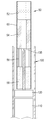
- FIG. 2 is a schematic view showing a partial exploded perspective view and a cross-sectional view of a smoking article according to a preferred embodiment that can be used in the complex heating aerosol generator of the present invention.
- FIG. 3 conceptually shows the components of the smoking article according to FIG. 2 and the configuration of the wrapping paper surrounding it.
- FIG. 4 is a conceptual diagram showing a process of manufacturing a moisture absorbent rod to obtain the moisture absorbent shown in FIG. 3.
- FIG. 5 conceptually shows a cutting process for cutting a liquid cartridge to manufacture a liquid cartridge that can be provided in a smoking article that can be used in the complex heating aerosol generator of the present invention from the moisture absorbent rod shown in FIG. 4.
- 6 to 20 are conceptual diagrams as follows of various embodiments of a complex heating aerosol generator for generating an aerosol from a smoking article that can be used in the present invention.
- FIG. 6 schematically shows a cross-sectional view of a smoking article applied to a complex heating aerosol generator in which a resistance heating type heater as a first heating unit and an induction heating type heater as a second heating unit are combined according to the first embodiment.
- FIG. 7 schematically shows a cross-sectional view of a smoking article applied to a complex heating aerosol generator in which a resistance heating type heater as a first heating unit and an induction heating type heater as a second heating unit are combined according to a second embodiment.
- FIG. 8 schematically shows a cross-sectional view of a smoking article applied to a complex heating aerosol generator in which a resistance heating type heater as a first heating means and an induction heating type heater are combined as a second heating means according to a third embodiment.
- FIG. 9 schematically shows a cross-sectional view of a smoking article applied to a complex heating aerosol generator in which a heater of an induction heating method as a first heating means and a heater of a resistance heating method as a second heating means are combined according to the fourth embodiment.
- FIG. 10 schematically shows a cross-sectional view of a smoking article applied to a complex heating aerosol generator in which an induction heating type heater as a first heating unit and a resistance heating type heater as a second heating unit are combined according to the fifth embodiment.
- FIG. 11 schematically shows a cross-sectional view of a smoking article applied to a complex heating aerosol generator in which an induction heating type heater as a first heating unit and a resistance heating type heater are combined as a second heating unit according to the sixth embodiment.
- FIG. 12 schematically shows a cross-sectional view of a smoking article applied to a complex heating aerosol generator in which a heater of an induction heating method as a first heating means and a heater of a resistance heating method as a second heating means are combined according to the seventh embodiment.
- FIG. 13 schematically shows a cross-sectional view of a smoking article applied to a complex heating aerosol generator in which a heater of an induction heating method as a first heating means and a heater of an induction heating method as a second heating means are combined according to an eighth embodiment.
- FIG. 14 schematically shows a cross-sectional view of a smoking article applied to a complex heating aerosol generator in which a heater of an induction heating method as a first heating means and a heater of an induction heating method as a second heating means are combined according to a ninth embodiment.
- FIG. 15 schematically shows a cross-sectional view of a smoking article applied to a complex heating aerosol generator in which a heater of an induction heating method as a first heating means and a heater of an induction heating method as a second heating means are combined according to the tenth embodiment.
- FIG. 16 schematically shows a cross-sectional view of a smoking article applied to a complex heating aerosol generator in which a heater of an induction heating method as a first heating means and a heater of an induction heating method as a second heating means are combined according to an eleventh embodiment.
- FIG. 17 schematically shows a cross-sectional view of a smoking article applied to a complex heating aerosol generator in which a heater of an induction heating method as a first heating means and a heater of an induction heating method as a second heating means are combined according to a twelfth embodiment.
- FIG. 18 schematically shows a cross-sectional view of a smoking article applied to a complex heating aerosol generator in which a heater of a resistance heating method as a first heating means and a heater of a resistance heating method as a second heating means are combined according to a thirteenth embodiment.
- FIG. 19 schematically shows a cross-sectional view of a smoking article applied to a complex heating aerosol generator in which a heater of a resistance heating method as a first heating means and a heater of a resistance heating method as a second heating means are combined according to a fourteenth embodiment.
- FIG. 20 schematically shows a cross-sectional view of a smoking article applied to a complex heating aerosol generator having a single resistance heating type heater as a first heating unit and a second heating unit according to the fifteenth embodiment.
- 21 is a block diagram according to an embodiment for explaining temperature control and heating time control in a complex heating aerosol generator in which a resistance heating type heater and an induction heating type heater according to the present invention are combined.
- 22 is a block diagram illustrating temperature control and heating time control in a complex heating aerosol generator in which an induction heating type heater and an induction heating type heater according to the present invention are combined.
- FIG. 23 is a block diagram illustrating temperature control and heating time control in a complex heating aerosol generator in which a resistance heating type heater and a resistance heating type heater according to the present invention are combined.
- 24 is a graph for explaining the time control according to the amount of puffing in the complex heating aerosol generating device according to the present invention.
- 25 is a graph for explaining an embodiment of temperature control and heating control in the complex heating aerosol generating apparatus according to the present invention.
- 26 is an embodiment of a circuit block diagram for explaining resonant frequency adjustment by controlling a capacitor switch of a controller in the complex heating aerosol generator according to the present invention.
- FIG. 27 is another embodiment of a circuit block diagram for explaining the control of the resonance frequency by the capacitor switch control of the controller in the complex heating aerosol generator according to the present invention.
- the composite heating aerosol generating device is a grippable and portable size aerosol for smoking articles having a first aerosol-forming material and a second aerosol-forming material upstream of the first aerosol-forming material.
- a generating device comprising: a cavity provided in the device, into which a smoking article can be inserted, and a first heating means provided in the device, capable of heating the inside or outside of the first aerosol-forming substrate of the smoking article to a first temperature range And, a second heating means capable of heating the inside or outside of the second aerosol-forming substrate of a smoking article provided in the apparatus to a second temperature range, and a first heating means and a second heating means provided in the apparatus.
- a first sensor and a second sensor respectively sensing temperature, a rechargeable battery provided in the device and functioning as a direct current power source, and a rechargeable battery provided in the device that is electrically connected to the first sensor and the second sensor and the battery, and supplied from the battery
- a controller configured to respectively control the first heating means and the second heating means according to the detected values of the first sensor and the second sensor by receiving DC power.
- the first aerosol-forming material provided in the smoking article is a liquid cartridge
- the second aerosol-forming material is a tobacco body
- the first aerosol-forming material provided in the smoking article is a cigarette body and the second aerosol-forming material is a liquid cartridge.
- the first aerosol-forming material and the second aerosol-forming material provided in the smoking article are tobacco bodies.
- the tobacco body comprises glycerin VG.
- the first aerosol-forming material and the second aerosol-forming material provided in the smoking article are liquid cartridges.
- the liquid cartridge contains a liquid or gel composition containing glycerin VG.
- the smoking article further includes a filter and a tube, and the filter, tube, cigarette sieve, and liquid cartridge are formed by wrapping with one wrapping paper.
- the smoking article further includes a filter and a tube, and the filter, the tube, and the tobacco body are formed by wrapping with one wrapping paper.
- the smoking article further includes a filter and a tube, and the filter, the tube, and the liquid cartridge are formed by wrapping with one wrapping paper.
- a pressure sensor provided in the device and electrically connected to the control unit is additionally provided, and the control unit calculates an integral value for the amount of puffing according to the detected value input from the pressure sensor, and then calculates the integral value according to the accumulated integral value. Controls the 1 heating means and/or the second heating means.
- the first heating means is a heater of a resistance heating type
- the second heating means is a heater of an induction heating type
- the first heating means is an induction heating type heater
- the second heating means is a resistance heating type heater
- the first heating means is an induction heating type heater
- the second heating means is an induction heating type heater
- the first heating means is a heater of a resistance heating type
- the second heating means is a heater of a resistance heating type
- the heater of the resistance heating method is a pipe heater including a heating resistance pattern.
- the heater of the resistance heating method is an invasive heater.
- the first heating means and the second heating means are integrally formed and inserted through the lower center of the smoking article inserted into the cavity to directly contact the first aerosol-forming material and the second aerosol-forming material in the smoking article. It is an invasive heater.
- the induction heating type heater is a susceptor that reacts with the excitation coil and the excitation coil to generate induction heating due to eddy current loss to heat smoking articles.
- a plurality of capacitor switches are provided in the device and connected between the control unit and the excitation coil, and the control unit controls at least one of the plurality of capacitor switches on-off to supply AC current to the excitation coil. Control the frequency of.
- a sensor for detecting the inductance of the excitation coil is provided.
- a sensor for sensing the impedance of the excitation coil is provided.
- it includes a heat insulating portion provided between the susceptor and the excitation coil to prevent heat of the susceptor from being transferred to the excitation coil.
- an insulating film using an insulating filler having an insulating shielding function is attached to the outer wall of the insulating pipe.
- the insulating filler is made of ceramic powder.
- the susceptor has a shape of a hollow pipe inserted into the center of the first aerosol-forming substrate and/or the second aerosol-forming substrate.
- the susceptor is made of at least one of stainless steel, nickel, and cobalt.
- the induction heating type heater is a susceptor that reacts with the excitation coil and the excitation coil to generate induction heating due to eddy current loss to heat the smoking article, and the susceptor penetrates the lower center of the smoking article inserted into the cavity. It is inserted to directly contact the second aerosol-forming substrate in the smoking article.
- the heater of the resistance heating method of the second heating means is an invasive heater.
- the terms'upstream' and'downstream' are terms used to indicate the relative positions of segments constituting the smoking article based on the direction in which the user sucks air using the smoking article.
- the smoking article includes an upstream end (ie, a portion from which air enters) and a downstream end opposite thereto (ie, a portion from which air exits).
- the user bites the downstream end of the smoking article, is sucked through the upstream end of the smoking article, passes through the inside of the smoking article, and inhales air exiting the downstream end.
- the downstream end is located downstream of the upstream end, while the term'end' may also be described as'end'.
- the composite heating aerosol-generating device is for a smoking article having a first aerosol-forming material and a second aerosol-forming material downstream of the first aerosol-forming material, and is grippable and portable.
- the first heating means and the second heating means for heating the inside or outside of the second aerosol-forming substrate of the smoking article provided in the apparatus to a second temperature range, and the first heating means and the second heating means provided in the apparatus 2
- a first sensor and a second sensor respectively sensing the temperature of the heating means, a rechargeable battery provided in the device and functioning as a direct current power source, and a rechargeable battery provided in the device to be electrically connected to the first sensor and the second sensor and the battery,
- a control unit for receiving DC power supplied from the battery and controlling the first heating means and the second heating means, respectively, according to detection values of the first sensor and the second sensor.
- FIG. 2 is a conceptual exploded perspective view and a cross-sectional view of a smoking article of a preferred embodiment that can be used in the complex heating aerosol generating device of the present invention
- FIG. 3 is a component of the smoking article according to FIG. It shows the composition of the paper conceptually.
- Smoking articles which can be used in the complex heating aerosol generator of the present invention, generate an aerosol from the smoking article by heating the smoking article in an electrical resistance method or an induction heating method without combustion, and the user inhales and uses the aerosol. It is a form of doing.
- Such smoking articles include an aerosol-forming substrate and/or a tobacco cut filler in an amount suitable for inhaling a number of times similar to that of a conventional smoking article, and a predetermined amount of aerosol After it has been generated it will no longer generate a significant amount of aerosol and will be discarded by the user after one use.
- the smoking article 50 that can be used in the complex heating aerosol generating device according to an embodiment of the present invention includes a tobacco body 58 including a tobacco cut filler as a second aerosol-forming material at an upstream end, and a first A liquid cartridge 56 containing a liquid composition as an aerosol-forming base material, a paper tube 54 providing an aerosol movement passage directly downstream thereof, and a filter 52 functioning as a mouthpiece are stacked, and these are wrapped. It is wrapped by paper 60.
- the smoking article 50 having the above-described structure will be described, but the relative positions of the liquid cartridge 56 made of the liquid composition and the tobacco body 58 made of the tobacco cut filler may be opposite according to embodiments.
- another liquid cartridge 56 may be disposed as a second aerosol-forming material at an upstream end of the liquid cartridge 56, which is the first aerosol-forming material.
- another cigarette body 58 as the first aerosol-forming material may be disposed at the downstream end of the cigarette body 58 that is the second aerosol-forming material.
- the liquid cartridge 56 includes a liquid or gel composition; A liquid or gel-like absorbent body wetted with a liquid or gel-like composition; It includes a wrapping paper that wraps the side of a liquid or gel absorbent in a cylinder shape having a length of 7 to 20 mm and a diameter of 5 to 8 mm, and the liquid or gel absorbent is a liquid or gel absorbent in a liquid cartridge It has a moisture absorption rate sufficient to absorb 70 to 120 mg of the liquid composition and keep it in the liquid cartridge.
- the cylinder shape having a length of 7 to 20 mm and a diameter of 5 to 8 mm is a size that conforms to the standard of conventional cigarettes or heated smoking articles in use, and the liquid cartridge 56 having such a size is inserted into the heated smoking article.
- a separate wrapping paper 60 there is no difference from a normal cigarette or heated smoking article from a user's point of view.
- a liquid or gel composition of 70 to 120 mg is absorbed in the liquid absorbent of the liquid cartridge 56 having this standard, and this numerical range is liquid when the user inhales aerosol from the tobacco cut filler provided in one smoking article. It refers to the amount of the liquid composition in an amount capable of providing together an aerosol derived from the composition. If a liquid or gel composition less than the above lower limit (70 mg) is absorbed by the liquid absorbent, the aerosol derived from the liquid composition may be insufficient in the process of inhaling the aerosol derived from tobacco cut filler provided in heated smoking articles. Therefore, the liquid composition absorbed by the liquid cartridge must be at least the lower limit value (70 mg).
- the liquid absorbent in the liquid cartridge having the above standard may be difficult to maintain the liquid composition while absorbing moisture. It can flow out of the liquid cartridge. Therefore, the liquid or gel composition absorbed by the liquid cartridge 56 should be less than the upper limit (120 mg).
- a preferred range is 80 to 110 mg, and a more preferred range is 90 to 105 mg.
- the liquid hygroscopic body in the liquid cartridge 56 having the above standard has a moisture absorption rate sufficient to maintain the liquid composition having the above range in the liquid cartridge. That is, the liquid composition remains absorbed by the liquid absorbent in the liquid cartridge, and does not flow out of the liquid cartridge.
- moisture absorption indicates that the moisture absorbent is wetted by the liquid composition, but does not flow out.
- the filter-tube-liquid cartridge-cigarette body is wrapped with wrapping paper to form a smoking article, and the liquid cartridge is in direct contact with the cigarette body, tube, or filter in the upstream or downstream side without a separate member.
- the liquid composition absorbed by the liquid absorbent inside is only absorbed and stored by the liquid absorbent, and does not flow out to the tobacco body or tube or filter.
- the liquid composition is preferably absorbed by the liquid absorbent in an amount of 0.13 to 0.32 mg/mm 3 per unit volume of the liquid absorbent.
- the reason for this numerical limitation is similar to the reason for the numerical limitation on the amount of the liquid composition absorbed by the liquid absorbent of the present invention. In other words, if it is less than the lower limit value (0.13 mg/mm 3 ), the amount of the liquid composition absorbed in the liquid absorbent is not sufficient, so the liquid composition in the process of inhaling the aerosol derived from the tobacco cut filler provided in the heated smoking article Since the aerosol derived from may be insufficient, the liquid composition absorbed by the liquid cartridge must be above the lower limit value (0.13 mg/mm 3 ). When a liquid composition exceeding the upper limit (0.32 mg/mm 3 ) is absorbed by the liquid absorbent, it may be difficult for the liquid composition to maintain the liquid composition while absorbing moisture in the liquid cartridge having the above standard. It can flow out from this liquid cartridge.
- the liquid composition comprises glycerin VG, and optionally comprises glycerin PG, water, and flavor, but the liquid composition is, by weight, 70 to 100% of glycerin VG, 0 to 20% of glycerin PG, 0 to 10% It includes water, and further includes a flavoring agent added to 10% or less of the total weight of the liquid composition thus obtained.
- the present invention uses a liquid composition consisting of 100% glycerin VG by weight.
- a liquid composition consisting of 80% glycerin VG and 20% glycerin PG, by weight is used.
- a liquid composition consisting of 75% glycerin VG, 20% glycerin PG and 5% water is used. According to another preferred embodiment, it further comprises a flavoring agent added to 10% or less based on the total weight of the liquid composition thus obtained.
- flavorings include licorice, sucrose, fructose syrup, isosweetener, cocoa, lavender, cinnamon, cardamom, celery, fenugreek, cascarilla, sandalwood, bergamot, geranium, honey essence, rose oil, vanilla, lemon Oil, orange oil, mint oil, cinnamon, caraway, cognac, jasmine, chamomile, menthol, cinnamon, ylang-ylang, sage, spearmint, ginger, cilantro or coffee.
- the liquid composition may or may not contain nicotine.
- the liquid absorbent is made of a cylindrical shape by crumpling or rolling a band having a thickness of 2 to 3 mm made of a melamine-based foam resin, and according to another preferred embodiment, the liquid absorbent is, a melamine-based foam It is made by processing the resin into a cylinder shape, and the liquid hygroscopic body made of a melamine-based foam resin, more preferably has a weight per unit volume of 0.01 to 0.013 mg/mm 3 . According to the results of an experiment conducted on smoking articles including a liquid cartridge having a liquid absorbent wetted with 100 mg of the liquid composition, the liquid composition remained absorbed by the liquid absorbent without a problem flowing out during the experiment. Sufficient aerosols from the composition have been identified.
- the liquid absorbent is made by crumpling, folding, rolling, or processing the pulp or fabric containing pulp into a cylinder shape, or a liquid absorbent made of pulp or fabric containing pulp. Is, more preferably 0.25 to 0.4 mg / mm 3 has a weight per unit volume. According to the results of an experiment conducted on smoking articles including a liquid cartridge having a liquid absorbent wetted with 100 mg of the liquid composition, the liquid composition remained absorbed by the liquid absorbent without a problem flowing out during the experiment. Sufficient aerosols from the composition have been identified.
- the liquid absorbent is made by crumpling or rolling a woven or nonwoven fabric of cotton to form a cylinder shape or processing it into a cylinder shape, and the liquid absorbent made of a woven or nonwoven fabric of cotton, More preferably, it has a weight per unit volume of 0.2 to 0.35 mg/mm 3 . According to the results of an experiment conducted on smoking articles including a liquid cartridge having a liquid absorbent wetted with 100 mg of the liquid composition, the liquid composition remained absorbed by the liquid absorbent without a problem flowing out during the experiment. Sufficient aerosols from the composition have been identified.
- the liquid absorbent according to the present invention is made by crumpling or rolling a woven or non-woven fabric of bamboo fiber into a cylinder shape or processing it into a cylinder shape.
- the resulting liquid absorbent has a weight per unit volume of more preferably 0.15 to 0.25 mg/mm 3 .
- the liquid cartridge 56 is present in a gel or solid phase at room temperature and vaporizes to an aerosol in a temperature range of 150 to 300 °C, comprising glycerin VG, water, gelatin, and optionally a gel phase comprising glycerin PG
- the cylinder shape having a length of 7 to 20 mm and a diameter of 5 to 8 mm is a size that conforms to the standard of conventional cigarettes or heated smoking articles in use, and a gel-like aerosol-forming substrate cartridge having such a standard is inserted into the heated smoking article. Therefore, if it is wrapped with a separate wrapping paper, there is no difference from a normal cigarette or heated smoking article from a user's point of view.
- the gel-like aerosol-forming substrate includes a liquid composition consisting of 80 to 100% glycerin VG and 0 to 20% glycerin PG in weight%, but the volume of 60 to 80% liquid composition and 20 to 40% water It includes gelatin in a weight of 1 to 6 g based on 100 ml of the mixture mixed at a ratio, and may optionally include a flavoring agent added to 10% or less of the total weight of the liquid composition.
- the liquid composition is contained in an amount of 70 to 120 mg in the gel container.
- the liquid composition may be included in the gel receptor in an amount of 0.13 to 0.32 mg/mm 3 per unit volume of the gel receptor.
- the tobacco body 58 may include a solid material based on tobacco raw materials such as plate-shaped tobacco, cut filler, and reconstituted tobacco.
- the tobacco body 58 may be filled with a corrugated platelet sheet.
- the platelet sheet may be rolled, folded, compressed, or contracted substantially transversely to the cylinder axis to form a wrinkle.
- the porosity can be determined by adjusting the bone spacing of the corrugated leaflet sheet.
- the tobacco body 58 may be filled with tobacco cut fillers.
- tobacco cut fillers can be produced by finely cutting a tobacco sheet (or a slurry platelet sheet).
- the tobacco body 58 may be formed by combining a plurality of tobacco strands in the same direction (parallel) or randomly.
- the tobacco body 58 may be formed by combining a plurality of tobacco strands, and a plurality of longitudinal channels through which an aerosol may pass may be formed. At this time, depending on the size and arrangement of the tobacco strands, the channels in the longitudinal direction may be uniform or non-uniform.
- the tobacco body 58 may further contain at least one of ethylene glycol, dipropylene glycol, diethylene glycol, triethylene glycol, tetraethylene glycol, and oleyl alcohol.
- the tobacco body may further include glycerin VG, glycerin and propylene glycol.
- the tobacco body 58 may contain other additives such as flavoring agents and/or organic acids.
- flavoring agents include licorice, sucrose, fructose syrup, isosweet, cocoa, lavender, cinnamon, cardamom, celery, fenugreek, cascarilla, sandalwood, bergamot, geranium, honey essence, rose oil, Vanilla, lemon oil, orange oil, mint oil, cinnamon, caraway, cognac, jasmine, chamomile, menthol, cinnamon, ylang-ylang, sage, spearmint, ginger, cilantro, or coffee.
- a wrapping paper 61 serving as a housing wraps the moisture absorbent 56a in which the liquid composition is absorbed. Further, at the downstream end of the liquid cartridge 56, a paper tube 54 and a filter 52 are sequentially stacked. The filter 52 and the paper tube 54 are wrapped by a wrapping paper 60 together with the liquid cartridge.
- the liquid composition in the liquid cartridge 56 is held in the liquid cartridge 56 while being absorbed by the absorbent, does not flow out of the liquid cartridge, and vaporizes by heating to generate an aerosol.
- the wrapping paper (60, 61, 62) is made of a material that does not deform due to high heat and contact with a liquid, or generates an ingredient harmful to the human body.
- the wrapping paper may be made of a metal thin film or a metal foil, and as described above, a metal thin film or a metal thin plate may be added to or laminated to a wrapping paper made of a paper material.
- the wrapping paper 61 serving as a housing of the liquid cartridge 56 is composed of a laminate of paper and aluminum foil, and the aluminum foil contacts the moisture absorbing body 56a so that the liquid composition is It is prevented from flowing out to the side of the liquid cartridge 56 while being absorbed by the hygroscopic body.
- the filter 52 on the downstream side of the liquid cartridge may have a hollow portion to form an airflow, but a filter having no hollow portion may be used.
- the filter may be composed of at least one segment, and may include, for example, at least one of a tube filter, a cooling structure, and a recess filter.
- the tube filter has a shape including a hollow inside.
- the tube filter and the recess filter may be made of cellulose acetate, and the tube serving as a cooling structure may be made of pure polylactic acid (PLA), or may be made by combining other degradable polymers and polylactic acid.
- the filter 52 may be made of a material such as acetate, paper, PP, etc.
- the filter wrapper (wrapping paper) surrounding the filter is made of plain paper, porous paper, perforated paper, NWA (Non Wrapped Acetate), etc. Can be classified.
- the shape of the filter can be classified into a mono filter composed of one segment and a composite (double, triple, etc.) filter composed of several segments.
- the filter can also be made of acetate tow, plasticizer, activated carbon, X-DNA, and roll paper.
- Acetate tow refers to an aggregate of continuous filaments of cellulose acetate and plays a decisive role in determining the most important characteristic of the filter, the suction resistance. The properties of the acetate tow are determined by Denia.
- Plasticizers make the cellulose acetate fibers soft and pliable, forming bonds at the points of contact between the fibers, and making the fiber bundle more rigid. Triacetin is used as a plasticizer for cigarette filters.
- Activated carbon one of the adsorbents, is a material mainly composed of carbon, and can be classified according to the size and properties of the particles.
- Raw materials used for activated carbon are vegetable raw materials such as wood, sawdust, and fruit kernels (palm, bamboo, peach seeds).
- X-DNA refers to functional particles that are extracted from seaweed and then concentrated and processed. Compared to activated carbon, which is mainly used for cigarette filters, it does not affect the taste of cigarettes and has excellent removal function of various carcinogens.
- wrapping paper maintains the shape of the filter floc when manufacturing the filter.
- physical properties such as porosity, tensile strength, elongation, thickness, and paste must be satisfied.
- the length of the liquid cartridge 56 may be 14.0 mm
- the length of the filter 52 or the tube 54 may be 2.5 mm
- the length of the tobacco body 58 including the tobacco cut filler may be 9.0 mm
- the filter 52 may be 10 mm
- the paper tube 54 may be 16 mm
- the liquid cartridge 56 may be 10 mm
- the cigarette body 58 may be 12 mm.
- the relative lengths of the filter 52, the paper tube 54, the liquid cartridge 56, and the cigarette body 58, and the relative arrangement of the liquid cartridge 56 and the cigarette body 58, are described later in the composite heating aerosol generator ( 100) may be related to the temperature of the aerosol in the process of inhaling the aerosol generated in the smoking article 50 by the user. Since the temperature of the aerosol generated from the liquid cartridge 56 and the temperature of the aerosol generated from the cigarette body 58 are different, and the length of the paper tube 54 increases, the high temperature aerosol can be further cooled.
- the volume of the liquid cartridge 56 and the cigarette body 58 may vary in consideration of the dependent liquid composition and the amount of tobacco cut filler and the heating method of the composite heating aerosol generator 100 to be described later. It will not be difficult for those of ordinary skill in the art to satisfy the above various conditions while manufacturing the smoking article in the same size as the currently available smoking article.
- FIG. 4 is a conceptual diagram showing a process of manufacturing a moisture absorbent rod to obtain the moisture absorbent shown in FIG. 3.
- a liquid such as a spray equipment or a needle before the absorbent formed in a cylinder shape by the pipe structure 40 is introduced into the pipe structure 40.
- the liquid composition is sufficiently sprayed or injected to provide the liquid composition into the absorbent body 56a, and the absorbent body 56a contains the liquid composition while passing through the pipe structure 40 or wetted by the liquid composition.
- the moisture absorbent in which the liquid composition is absorbed is wrapped with a wrapping paper made of, for example, paper (or paper laminated with aluminum foil), and cut to the required length (for example, 140 mm, 100 mm or 80 mm).
- a hygroscopic rod 57 is formed.
- the absorbent rod 57 is cut into a liquid cartridge 56 of a desired length (for example, 14 mm, 10 mm, 8 mm), as described later, and then the segments (tube, filter, cigarette body) of other smoking articles and Packed together (wrapped) can be made into an aerosol-generating smoking article 50.
- a desired length for example, 14 mm, 10 mm, 8 mm
- FIG. 5 conceptually shows a cutting process for cutting a liquid cartridge to manufacture a liquid cartridge that can be provided in a smoking article that can be used in the complex heating aerosol generator of the present invention from the moisture absorbent rod shown in FIG. 4.
- FIG. 5 schematically shows a cutting process for cutting the hygroscopic rod 57 obtained as above to manufacture the liquid cartridge 56, and has a length of 140 mm, 100 mm or 80 mm as an example as described above.
- the absorbent rod 57 is introduced into the groove of the index table 70 and is moved to the conveyor belt 90 according to the rotation of the index table.
- the rotating blade 80 is disposed on the path moving along the index table 70, and the absorbent rod 57 is 10 to a desired length, for example, 14 mm, 10 mm, 80 mm length by the rotating blade. It is cut into three liquid cartridges 56.
- Ten rotary blades 80 are arranged at equal intervals, cutting a 140mm absorbent rod 57 into ten 14 mm liquid cartridges 56, or cutting a 100 mm absorbent rod 57 into ten 10 mm
- the liquid cartridge 56 may be cut, or an 80 mm hygroscopic rod 57 may be cut into 10 8 mm liquid cartridges 56.
- the above processes and equipment are used as they are in the case of including fragrance components in filters in conventional cigarette manufacturing, so there is no great difficulty in satisfying mass production and quality control as they are.
- a filter 52 serving as a mouthpiece is located at a downstream end of the liquid cartridge 56, and a tobacco body 58 including tobacco cut filler is located at an upstream end of the liquid cartridge 56.
- Each of these segments can be packed together to produce an aerosol-generating smoking article 50.
- a tube 54 may be positioned between the filter 52 and the liquid cartridge 56 to provide a passage for moving the aerosol and cool the aerosol if necessary.
- Each of these segments, a filter 52, a tube 54, a liquid cartridge 56, and a cigarette body 58 are arranged side by side and packed together to obtain a smoking article 50 for generating an aerosol. In an actual production line, these can be arranged in sets of 10 or more side by side and cut into multiple smoking articles after lapping.
- the liquid composition of the liquid cartridge 56 remains absorbed by the moisture absorbing body 56a in the liquid cartridge, and does not flow out of the liquid cartridge 61, but in the process of manufacturing smoking articles or completing smoking articles. Later, due to the high temperature or physical pressure applied to the liquid cartridge, it is possible to consider a case in which the liquid dry matter flows out or vaporizes with an aerosol to come out.
- the tobacco body is located upstream of the liquid cartridge, and the filter is located downstream of the liquid cartridge, so even if physical pressure is applied to the liquid cartridge from the outside, the liquid dried product passes through the filter or cigarette body to the outside. It is extremely unlikely to flow out. Since the liquid composition starts to generate an aerosol at about 120° C.
- the loss of the liquid composition during the manufacturing process can be prevented by wrapping the liquid cartridge 56 or controlling the process in the manufacturing process to 100° C. or less.
- the amount of the liquid composition lost during the process is estimated and the amount expected to be lost is added to the required amount, and the liquid composition can be further absorbed and managed. have.
- the composite heating aerosol generating device 100 described below includes an aerosol-forming material such as a liquid composition or a tobacco cut filler inside the smoking article, like the smoking article 50 described in the present invention, and is a wrapping paper in the form of a conventional cigarette.
- a grippable and portable size having a cavity into which the wrapped smoking article 50 can be inserted, and heating the aerosol-forming substrate of the smoking article inserted in the cavity by a heating means provided in the aerosol generator to form an aerosol.
- the heating means may be provided by a resistance heating method or an induction heating method, as will be described later, for example, a smoking article 50 that is heated to a temperature of 100 to 400° C. and inserted into the cavity of the complex heating aerosol generator 100
- An aerosol is generated by heating the aerosol-forming substrate provided inside.
- the target temperature may be in the range of 200 to 350 °C, and according to a more preferred example, the target temperature may be in the range of 250 to 320 °C (for example, 280 °C may be set as the target. May be).
- the target temperature may be in the range of 150 to 250 °C (for example, 180 °C may be set as the target temperature), which is whether the object to generate an aerosol is a liquid composition (glycerin, etc.) or a cigarette. Alternatively, it may vary depending on whether a liquid composition such as glycerin is a moisture absorbed cigarette.
- the target temperature of the heating element should be determined in advance in consideration of this point. Further, for the above reason, the upper limit of the target temperature of the heating element is limited as described above.
- the temperature of the generated aerosol passing through the tube 54 and the filter 52 may be measured as a mouth end temperature.
- the temperature of the aerosol is 50°C. It should be at a temperature of less than, preferably not more than 45°C.
- a preferred aerosol mouth end temperature has a temperature range of 25 to 45 °C, and a more preferred aerosol mouth end temperature has a temperature range of 30 to 40 °C.
- the complex heating aerosol generator 100 includes both a rechargeable battery 110 provided in the device and functioning as a DC power source, and a controller 120 that controls an output from the battery 110.
- FIG. 6 a conceptual diagram of the complex heating aerosol generator 100 is shown together with the smoking article 50, and is schematically shown in cross-sectional view for use in explaining the heating method for each embodiment.
- the smoking article 50 which is a smoking article, is basically a filter 52-a tube 54-a liquid cartridge 56 as a first aerosol-forming material-a cigarette body 58 as a second aerosol-forming material It will be described on the basis of being arranged in the order of and wrapped with wrapping paper 60.
- the relative positions of the liquid cartridge 56 and the cigarette body 58 may be interchanged, and according to the embodiment, the filter 52-the tube 54-the liquid cartridge 56-the liquid cartridge It may be arranged in the order of 56 or may be arranged in the order of filter 52-tube 54-cigarette body 58-cigarette body 58.
- FIG. 6 schematically shows a cross-sectional view of a smoking article applied to a complex heating aerosol generator in which a resistance heating type heater as a first heating unit and an induction heating type heater as a second heating unit are combined according to the first embodiment.
- a smoking article 50 is inserted into the complex heating aerosol generator 100, and the smoking article 50 includes a filter 52, a paper tube 54, a liquid cartridge 56, and a cigarette body 58 as described above. Is wrapped by the wrapping paper 60 and is inserted into the hollow provided in the composite heating aerosol generating device 100.
- the complex heating aerosol generating device 100 is a first heating means for generating an aerosol by heating the liquid composition absorbed in the liquid cartridge 56, and heats the pipe heater 131 and the tobacco cut filler of the tobacco body 58.
- a second heating means for generating an aerosol it includes a susceptor that reacts with the excitation coil 142 and the excitation coil 142 to generate induction heat generated by eddy current loss to heat the tobacco body 58.
- a battery 110 for supplying power to the pipe heater 131 and the excitation coil 142, and a control unit configured to control the supply of power from the battery 110 to the pipe heater 131 and the excitation coil 142 Includes 120.
- the pipe heater 131 is a pipe in which a heater wire or a planar heating element pattern is printed or provided on the outside.
- a temperature sensor pattern is provided to the pipe heater 131 so that the temperature is sensed and power supply to the pipe heater 131 can be controlled according to the sensing value.
- the pipe heater 131 heats the liquid cartridge 56 from the side of the liquid cartridge 56 of the smoking article 50 so that the liquid composition wet or contained in the liquid cartridge 56 is heated to generate an aerosol. .
- the susceptor is made of a metal material that is provided inside the excitation coil 142 so that the excitation coil 142 is surrounded, reacts with the excitation coil 142 and is heated to a temperature of 400° C. or less by induction heating due to eddy current loss. It is a heat pipe 141. Depending on the magnitude of the alternating current applied to the excitation coil 142, the temperature of the susceptor may be heated up to a temperature of 1000° C. or higher, but the present invention applies the susceptor functioning as a heating element to a temperature of 400° C. or less as described above. To heat.
- the heat pipe 141 heats the tobacco body 58 from the side surface of the tobacco body 58 to generate an aerosol from the tobacco cut filler and the like provided in the tobacco body 58.
- the aerosol may be generated by heating the aerosol generating base material to a temperature range of 150-350 °C by the above first heating means and the second heating means, and the aerosol generated by the user's inhalation may be a paper tube 54 and a filter ( 52) and inhaled through the user's mouth.
- the excitation coil 142 and the susceptor may generate an aerosol derived from the tobacco cut filler by heating the tobacco cut filler of the tobacco body 58 to a second temperature range of 150-250 °C, and the pipe heater 131
- the aerosol derived from the liquid composition of the absorbent may be generated by heating the moisture absorbent of the liquid cartridge 56 to a first temperature range of 250-350°C.
- the above temperature conditions may be opposite to each other.
- the second temperature range may overlap at least some sections with the first temperature range. Even if heated to the above temperature range, the wrapping paper does not burn, and a portion of the wrapping paper may leak.
- FIG. 7 schematically shows a cross-sectional view of a smoking article applied to a complex heating aerosol generator in which a resistance heating type heater as a first heating unit and an induction heating type heater as a second heating unit are combined according to a second embodiment.
- the configuration of the smoking article 50 is the same as in the case of the first embodiment.
- the composite heating aerosol generating device 100 according to the second embodiment is a pipe heater 131 and a tobacco body 58 as first heating means for generating an aerosol by heating a liquid composition absorbed in the liquid cartridge 56
- a susceptor that reacts with the excitation coil 142 and the excitation coil 142 to generate induction heat generated by eddy current loss and heats the tobacco body 58 Include.
- a battery 110 for supplying power to the pipe heater 131 and the excitation coil 142, and a controller configured to control the supply of power from the battery 110 to the pipe heater 131 and the excitation coil 142 ( 120).
- the pipe heater 131 is a pipe in which a heater wire or a planar heating element pattern is printed or provided on the outside.
- a temperature sensor pattern is provided to the pipe heater 131 so that the temperature is sensed and power supply to the pipe heater 131 can be controlled according to the sensing value.
- the pipe heater 131 heats the liquid cartridge 56 from the side of the liquid cartridge 56 of the smoking article 50 so that the liquid composition wet or contained in the liquid cartridge 56 is heated to generate an aerosol. .
- the susceptor is a hollow pipe 143 that is coupled to the center of the tobacco body 58 and reacts with the excitation coil 142 and is heated to a temperature of 400° C. or less by induction heating due to eddy current loss.
- the hollow provided in the hollow pipe 143 is used as an airflow path.
- the temperature of the susceptor may be heated up to a temperature of 1000° C. or higher, but the present invention applies the susceptor functioning as a heating element to a temperature of 400° C. or less as described above. To heat.
- the hollow pipe 143 heats the tobacco body 58 from the center of the tobacco body 58 to generate an aerosol from the tobacco cut filler and the like provided in the tobacco body 58.
- the hollow pipe 143 is made of one of stainless steel, nickel, and cobalt, but may be plated with one of stainless, nickel, and cobalt, and in some cases, a better effect may be obtained by plating.
- the aerosol may be generated by heating the aerosol generating base material to a temperature range of 150-350 °C by the above first heating means and the second heating means, and the aerosol generated by the user's inhalation may be a paper tube 54 and a filter ( 52) and inhaled through the user's mouth.
- the excitation coil 142 and the susceptor may generate an aerosol derived from the tobacco cut filler by heating the tobacco cut filler of the tobacco body 58 to a second temperature range of 150-250 °C, and the pipe heater 131
- the aerosol derived from the liquid composition of the absorbent may be generated by heating the moisture absorbent of the liquid cartridge 56 to a first temperature range of 250-350°C.
- the above temperature conditions may be opposite to each other.
- the second temperature range may overlap at least some sections with the first temperature range. Even if heated to the above temperature range, the wrapping paper does not burn, and a portion of the wrapping paper may leak.
- FIG. 8 schematically shows a cross-sectional view of a smoking article applied to a complex heating aerosol generator in which a resistance heating type heater as a first heating unit and an induction heating type heater are combined as a second heating unit according to a third embodiment.
- the configuration of the smoking article 50 is the same as that of the above-described embodiment.
- the composite heating aerosol generating device 100 according to the third embodiment is a pipe heater 131 and a tobacco body 58 as first heating means for generating an aerosol by heating a liquid composition absorbed in the liquid cartridge 56
- a susceptor that reacts with the excitation coil 142 and the excitation coil 142 to generate induction heat generated by eddy current loss and heats the tobacco body 58 Include.
- a battery 110 for supplying power to the pipe heater 131 and the excitation coil 142, and a control unit configured to control the supply of power from the battery 110 to the pipe heater 131 and the excitation coil 142 Includes 120.
- the pipe heater 131 is a pipe in which a heater wire or a planar heating element pattern is printed or provided on the outside.
- a temperature sensor pattern is provided to the pipe heater 131 so that the temperature is sensed and power supply to the pipe heater 131 can be controlled according to the sensing value.
- the pipe heater 131 heats the liquid cartridge 56 from the side of the liquid cartridge 56 of the smoking article 50 so that the liquid composition wet or contained in the liquid cartridge 56 is heated to generate an aerosol. .
- the susceptor is a heat blade 144 in which the susceptor is inserted through the lower center of the smoking article 50 inserted into the cavity to directly contact the tobacco body 58 as the second aerosol-forming material in the smoking article 50 It reacts with the excitation coil 142 and is heated to a temperature of 400° C. or less by induction heating due to eddy current loss. Depending on the magnitude of the alternating current applied to the excitation coil 142, the temperature of the susceptor may be heated up to a temperature of 1000° C. or higher, but the present invention applies the susceptor functioning as a heating element to a temperature of 400° C. or less as described above. To heat.
- the heat blade 144 is inserted through the cigarette body 58 and heats the cigarette body 58 from the center of the cigarette body 58 to generate an aerosol from a tobacco cut filler and the like provided in the cigarette body 58.
- the aerosol may be generated by heating the aerosol generating base material to a temperature range of 150-350 °C by the above first heating means and the second heating means, and the aerosol generated by the user's inhalation may be a paper tube 54 and a filter ( 52) and inhaled through the user's mouth.
- the excitation coil 142 and the susceptor may generate an aerosol derived from the tobacco cut filler by heating the tobacco cut filler of the tobacco body 58 to a second temperature range of 150-250 °C, and the pipe heater 131
- the aerosol derived from the liquid composition of the absorbent may be generated by heating the moisture absorbent of the liquid cartridge 56 to a first temperature range of 250-350°C.
- the above temperature conditions may be opposite to each other.
- the second temperature range may overlap at least some sections with the first temperature range. Even if heated to the above temperature range, the wrapping paper does not burn, and a portion of the wrapping paper may leak.
- FIG. 9 schematically shows a cross-sectional view of a smoking article applied to a complex heating aerosol generator in which a heater of an induction heating method as a first heating means and a heater of a resistance heating method as a second heating means are combined according to the fourth embodiment.
- the configuration of the smoking article 50 is the same as that of the above-described embodiment.
- the composite heating aerosol generating device 100 is a first heating means for generating an aerosol by heating a liquid composition absorbed in the liquid cartridge 56, and the excitation coil 142 and the excitation coil 142 It includes a susceptor for heating the liquid cartridge 56 by reaction and induced heat loss due to eddy current loss, and a hollow pipe 133 for generating an aerosol by heating the tobacco cut filler of the tobacco body 58 as a second heating means. do.
- a battery 110 for supplying power to the excitation coil 142 and the hollow pipe 133, and a controller configured to control the supply of power from the battery 110 to the excitation coil 142 and the hollow pipe 133 Includes 120.
- the susceptor according to the fourth embodiment described above reacts with the excitation coil 142 provided inside the excitation coil 142 so that the excitation coil 142 is enclosed by induction heating due to eddy current loss.
- It is a heat pipe 141 made of a metal material heated to a temperature.
- the temperature of the susceptor may be heated up to a temperature of 1000° C. or higher, but the present invention applies the susceptor functioning as a heating element to a temperature of 400° C. or less as described above.
- the heat pipe 141 heats the liquid cartridge 56 from the side of the liquid cartridge 56 so that the liquid composition wet or contained in the liquid cartridge 56 is heated to generate an aerosol.
- the hollow pipe 133 is coupled to the center of the tobacco body 58 and is a resistance heating type heater, such as tobacco cut filler provided in the tobacco body 58 by heating the tobacco body 58 from the center of the cigarette body 58 Generate an aerosol from
- the hollow pipe 133 is made of one of stainless steel, nickel, and cobalt, but may be plated with one of stainless steel, nickel, and cobalt, and in some cases, a better effect may be obtained by plating.
- the aerosol may be generated by heating the aerosol generating base material to a temperature range of 150-350 °C by the above first heating means and the second heating means, and the aerosol generated by the user's inhalation may be a paper tube 54 and a filter ( 52) and inhaled through the user's mouth.
- FIG. 10 schematically shows a cross-sectional view of a smoking article applied to a complex heating aerosol generator in which an induction heating type heater as a first heating unit and a resistance heating type heater as a second heating unit are combined according to the fifth embodiment.
- the configuration of the smoking article 50 is the same as that of the above-described embodiment.
- the composite heating aerosol generating apparatus 100 includes an excitation coil 142 and an excitation coil 142 as a first heating means for generating an aerosol by heating a liquid composition absorbed in the liquid cartridge 56.
- control unit 120 to control the supply of power to the excitation coil 142 and the batter 110 for supplying power to the invasive heater 134 and the excitation coil 142 and the invasive heater 134 from the battery 110 It includes a configured control unit 120.
- the susceptor according to the fifth embodiment described above reacts with the excitation coil 142 provided inside the excitation coil 142 so that the excitation coil 142 is surrounded by induction heating due to an eddy current loss at a temperature of 400° C. or less.
- It is a heat pipe 141 made of a metal material heated to a temperature.
- the temperature of the susceptor may be heated up to a temperature of 1000° C. or higher, but the present invention applies the susceptor functioning as a heating element to a temperature of 400° C. or less as described above. To heat.
- the heat pipe 141 heats the liquid cartridge 56 from the side of the liquid cartridge 56 so that the liquid composition wet or contained in the liquid cartridge 56 is heated to generate an aerosol.
- the invasive heater 134 is a resistance heating type heater that is inserted through the cigarette body 58 and inserted into the cigarette body 58, and heats the cigarette body 58 from the center of the cigarette body 58 An aerosol is generated from the tobacco cut filler and the like provided in (58).
- the aerosol may be generated by heating the aerosol generating base material to a temperature range of 150-350 °C by the above first heating means and the second heating means, and the aerosol generated by the user's inhalation may be a paper tube 54 and a filter ( 52) and inhaled through the user's mouth.
- FIG. 11 schematically shows a cross-sectional view of a smoking article applied to a complex heating aerosol generator in which an induction heating type heater as a first heating unit and a resistance heating type heater are combined as a second heating unit according to the sixth embodiment.
- the configuration of the smoking article 50 is the same as that of the above-described embodiment.
- the complex heating aerosol generating apparatus 100 heats the liquid composition absorbed in the liquid cartridge 56 to generate an aerosol, and includes an excitation coil 142 and an excitation coil 142 as a first heating means. It includes a susceptor for heating the liquid cartridge 56 in response to induction heating due to eddy current loss, and a pipe heater 131 for generating an aerosol by heating the tobacco cut filler of the tobacco body 58 as a second heating means. do.
- a batter 110 for supplying power to the excitation coil 142 and the pipe heater 131, and a controller configured to control the supply of power from the battery 110 to the excitation coil 142 and the pipe heater 131 Includes 120.
- the susceptor according to the sixth embodiment described above is coupled to the center of the liquid cartridge 56 and reacts with the excitation coil 142 to heat up to a temperature of 400° C. or less by induction heating due to eddy current loss. to be.
- the hollow provided in the hollow pipe 143 is used as an airflow path.
- the temperature of the susceptor may be heated up to a temperature of 1000° C. or higher, but the present invention applies the susceptor functioning as a heating element to a temperature of 400° C. or less as described above.
- the hollow pipe 143 is made of one of stainless steel, nickel, and cobalt, but may be plated with one of stainless, nickel, and cobalt, and in some cases, a better effect may be obtained by plating.
- the pipe heater 131 is a pipe in which a heater wire or a planar heating element pattern is printed or provided outside.
- a temperature sensor pattern is provided to the pipe heater 131 so that the temperature is sensed and power supply to the pipe heater 131 can be controlled according to the sensing value.
- the pipe heater 131 heats the tobacco body 58 from the side of the tobacco body 58 to generate an aerosol from a tobacco cut filler and the like provided in the tobacco body 58.
- the aerosol may be generated by heating the aerosol generating base material to a temperature range of 150-350 °C by the above first heating means and the second heating means, and the aerosol generated by the user's inhalation may be a paper tube 54 and a filter ( 52) and inhaled through the user's mouth.
- FIG. 12 schematically shows a cross-sectional view of a smoking article applied to a complex heating aerosol generator in which a heater of an induction heating method as a first heating means and a heater of a resistance heating method as a second heating means are combined according to the seventh embodiment.
- the configuration of the smoking article 50 is the same as that of the above-described embodiment.
- the composite heating aerosol generating device 100 heats the liquid composition absorbed in the liquid cartridge 56 to generate an aerosol, and includes an excitation coil 142 and an excitation coil 142 as a first heating means.
- control unit 120 to control the supply of power to the excitation coil 142 and the batter 110 for supplying power to the invasive heater 134 and the excitation coil 142 and the invasive heater 134 from the battery 110 It includes a configured control unit 120.
- the susceptor according to the seventh embodiment described above is coupled to the center of the liquid cartridge 56 and reacts with the excitation coil 142 to heat up to a temperature of 400° C. or less by induction heating due to eddy current loss. to be.
- the hollow provided in the hollow pipe 143 is used as an airflow path.
- the temperature of the susceptor may be heated up to a temperature of 1000° C. or higher, but the present invention applies the susceptor functioning as a heating element to a temperature of 400° C. or less as described above.
- the hollow pipe 143 is made of one of stainless steel, nickel, and cobalt, but may be plated with one of stainless, nickel, and cobalt, and in some cases, a better effect may be obtained by plating.
- the invasive heater 134 is a resistance heating type heater that is inserted through the cigarette body 58 and heated the cigarette body 58 from the center of the cigarette body 58 to provide a tobacco cut filler in the cigarette body 58. It generates an aerosol from the back.
- the aerosol may be generated by heating the aerosol generating base material to a temperature range of 150-350 °C by the above first heating means and the second heating means, and the aerosol generated by the user's inhalation may be a paper tube 54 and a filter ( 52) and inhaled through the user's mouth.
- FIG. 13 schematically shows a cross-sectional view of a smoking article applied to a complex heating aerosol generator in which a heater of an induction heating method as a first heating means and a heater of an induction heating method as a second heating means are combined according to an eighth embodiment.
- the configuration of the smoking article 50 is the same as that of the above-described embodiment.
- the complex heating aerosol generator 100 reacts with the excitation coil 142a and the excitation coil 142a corresponding to the liquid cartridge 56 as a first heating means, and induction heat generation occurs due to eddy current loss. Induction heating by eddy current loss reacts with the heat pipe 141a as a susceptor for heating the liquid cartridge 56 and the excitation coil 142b and the excitation coil 142b corresponding to the tobacco body 58 as a second heating means Each of the heat pipes 141b is provided as a susceptor for heating the tobacco body 58.
- the heat pipe 141a generates an aerosol from the liquid composition wet or contained in the liquid cartridge by heating the liquid cartridge 56 from the side of the liquid cartridge 56 of the smoking article 50, and the heat pipe 141b
- the cigarette body 58 is heated from the side of the cigarette body 58 of the smoking article 50 to generate an aerosol from the tobacco cut filler and the like provided in the cigarette body 58.
- the heat pipes 141a and 141b of the eighth embodiment make it possible to heat the liquid cartridge 56 and the tobacco body 58 to different temperatures.
- the target temperature may be in the temperature range of 150-350 °C, and the temperature may be adjusted according to the temperature sensing value, and the generated aerosol passes through the paper tube 54 and the filter 52 by inhalation of the user.
- the heat pipe 141b heats the tobacco cut filler of the tobacco body 58 to a second temperature range of 150-250° C. to generate an aerosol derived from the tobacco cut filler
- the heat pipe 141a is a liquid cartridge
- the aerosol derived from the liquid composition of the absorbent may be generated by heating the absorbent of 56) in the first temperature range of 250-350°C.
- the above temperature conditions may be opposite to each other.
- the second temperature range may overlap at least some sections with the first temperature range. Even if heated to the above temperature range, the wrapping paper does not burn, and a portion of the wrapping paper may leak.
- FIG. 14 schematically shows a cross-sectional view of a smoking article applied to a complex heating aerosol generator in which a heater of an induction heating method as a first heating means and a heater of an induction heating method as a second heating means are combined according to a ninth embodiment.
- the composite heating aerosol generator 100 according to the ninth embodiment has the same configuration as the eighth embodiment, between the excitation coil 142a and the heat pipe 141a and between the excitation coil 142b and the heat pipe 141b. Insulation portions 145a and 145b are provided respectively.
- the heat insulation parts 145a and 145b may be heat insulation pipes having a pipe shape into which the smoking article 50 is inserted.
- the intensity of is weakened, and thus the amount of induced heat generated in the heat pipes 141a and 141b is lowered. Therefore, by disposing the heat insulation parts 145a and 145b between the excitation coils 142a and 142b and the heat pipes 141a and 141b, the amount of heat generated by the heat pipes 141a and 141b can be improved. In addition, since the energy loss is small, there is an advantage that it becomes easy to control the heating temperature of the heat pipes 141a and 141b.
- An insulating film using a filler having an insulating shielding function may be attached to the outer walls of the insulating portions 145a and 145b applied for heat insulation, thereby increasing the heat insulating effect of the insulating portions 145a and 145b.
- the insulating filler ceramic powder such as zirconia having low thermal conductivity, porous silica gel, porous alumina, and aerogel may be used.
- the insulation effect of the insulator may be increased by applying an insulation paint using a filler having an insulation shielding function to the outer walls of the insulation parts 145a and 145b applied for insulation.
- a filler having an insulation shielding function As the insulating filler, ceramic powder such as zirconia having low thermal conductivity, porous silica gel, porous alumina, and aerogel may be used.
- the above-described heat insulation parts 145a and 145b may be provided between the excitation coil and the susceptor in other embodiments including an induction heating type heater in the complex heating aeroball generator 100 according to the present invention.
- FIG. 15 schematically shows a cross-sectional view of a smoking article applied to a complex heating aerosol generator in which a heater of an induction heating method as a first heating means and a heater of an induction heating method as a second heating means are combined according to the tenth embodiment.
- the configuration of the smoking article 50 is the same as that of the above-described embodiment.
- the complex heating aerosol generator 100 reacts with the excitation coil 142a and the excitation coil 142a corresponding to the liquid cartridge 56 as a first heating means to generate induced heat generation due to eddy current loss. Induction heating by eddy current loss reacts with the heat pipe 141 as a susceptor for heating the liquid cartridge 56 and the excitation coil 142b and the excitation coil 142b corresponding to the tobacco body 58 as a second heating means Each of the heat blades 144 is provided as a susceptor for heating the tobacco body 58.
- the heat pipe 141 heats the liquid cartridge 56 from the side of the liquid cartridge 56 of the smoking article 50 to generate an aerosol from the liquid composition wet or contained in the liquid cartridge, and the heat blade 144
- the cigarette body 58 is inserted through the cigarette body 58 and heated from the center of the cigarette body 58 to generate an aerosol from the tobacco cut filler and the like provided in the cigarette body 58.
- the heat pipe 141 and the heat blade 144 of the tenth embodiment enable heating the liquid cartridge 56 and the tobacco body 58 to different temperatures.
- the target temperature may be in the temperature range of 150-350 °C, and the temperature may be adjusted according to the temperature sensing value, and the generated aerosol passes through the paper tube 54 and the filter 52 by inhalation of the user. It is inhaled through the user's mouth.
- the heat blade 144 may generate an aerosol derived from the tobacco cut filler by heating the tobacco cut filler of the tobacco body 58 to a second temperature range of 150-250 °C
- the heat pipe 141 may be a liquid cartridge ( The aerosol derived from the liquid composition of the absorbent may be generated by heating the absorbent of 56) in the first temperature range of 250-350°C.
- the above temperature conditions may be opposite to each other.
- the second temperature range may overlap at least some sections with the first temperature range. Even if heated to the above temperature range, the wrapping paper does not burn, and a portion of the wrapping paper may leak.
- FIG. 16 schematically shows a cross-sectional view of a smoking article applied to a complex heating aerosol generator in which a heater of an induction heating method as a first heating means and a heater of an induction heating method as a second heating means are combined according to an eleventh embodiment.
- the configuration of the smoking article 50 is the same as that of the above-described embodiment.
- the complex heating aerosol generator 100 reacts with the excitation coil 142a and the excitation coil 142a corresponding to the liquid cartridge 56 as a first heating means, and induction heat generation occurs due to eddy current loss. Reaction with the hollow pipe 143 as a susceptor for heating the liquid cartridge 56 and the excitation coil 142b and the excitation coil 142b corresponding to the tobacco body 58 as a second heating means, and induced heat generation by eddy current loss Each of the heat blades 144 is provided as a susceptor for heating the tobacco body 58.
- the hollow pipe 143 heats the liquid cartridge 56 from the center of the liquid cartridge 56 of the smoking article 50 to generate an aerosol from the liquid composition wet or contained in the liquid cartridge, and the heat blade 144
- the tobacco body 58 is inserted through the cigarette body 58 and heated from the center of the cigarette body 58 to generate an aerosol from the tobacco cut filler and the like provided in the cigarette body 58.
- the hollow provided in the hollow pipe 143 is used as an airflow path.
- the hollow pipe 143 is made of one of stainless steel, nickel, and cobalt, but may be plated with one of stainless, nickel, and cobalt, and in some cases, a better effect may be obtained by plating.
- the hollow pipe 143 and the heat blade 144 of the eleventh embodiment make it possible to heat the liquid cartridge 56 and the tobacco body 58 to different temperatures.
- the target temperature may be in the temperature range of 150-350 °C, and the temperature may be adjusted according to the temperature sensing value, and the generated aerosol passes through the paper tube 54 and the filter 52 by inhalation of the user. It is inhaled through the user's mouth.
- the heat blade 144 may heat the tobacco cut filler of the tobacco body 58 to a second temperature range of 150-250° C.
- the hollow pipe 143 is a liquid cartridge
- the aerosol derived from the liquid composition of the absorbent may be generated by heating the absorbent of 56) in the first temperature range of 250-350°C.
- the above temperature conditions may be opposite to each other.
- the second temperature range may overlap at least some sections with the first temperature range. Even if heated to the above temperature range, the wrapping paper does not burn, and a portion of the wrapping paper may leak.
- FIG. 17 schematically shows a cross-sectional view of a smoking article applied to a complex heating aerosol generator in which a heater of an induction heating method as a first heating means and a heater of an induction heating method as a second heating means are combined according to a twelfth embodiment.
- the configuration of the smoking article 50 is the same as that of the above-described embodiment.
- the complex heating aerosol generating apparatus 100 reacts with the excitation coil 142a and the excitation coil 142a corresponding to the liquid cartridge 56 as a first heating means to generate induced heat generation due to eddy current loss.
- each of the hollow pipes 143b is provided.
- the hollow pipe 143a heats the liquid cartridge 56 from the center of the liquid cartridge 56 of the smoking article 50 to generate an aerosol from the liquid composition wet or contained in the liquid cartridge, and the hollow pipe 143b
- the cigarette body 58 is heated from the center of the cigarette body 58 to generate an aerosol from the tobacco cut filler and the like provided in the cigarette body 58.
- the hollow provided in the hollow pipes 143a and 143b is used as an airflow path.
- the hollow pipes 143a and 143b are made of one of stainless steel, nickel, and cobalt, but may be plated with one of stainless steel, nickel, and cobalt, and in some cases, a better effect may be obtained by plating.
- the hollow pipe 143a and the hollow pipe 143b of the twelfth embodiment make it possible to heat the liquid cartridge 56 and the tobacco body 58 to different temperatures.
- the target temperature may be in the temperature range of 150-350 °C, and the temperature may be adjusted according to the temperature sensing value, and the generated aerosol passes through the paper tube 54 and the filter 52 by inhalation of the user. It is inhaled through the user's mouth.
- the hollow pipe (143b) can generate an aerosol derived from the tobacco cut filler by heating the tobacco cut filler of the tobacco body 58 to a second temperature range of 150-250 °C
- the hollow pipe (143a) is a liquid cartridge
- the aerosol derived from the liquid composition of the absorbent may be generated by heating the absorbent of 56) in the first temperature range of 250-350°C.
- the above temperature conditions may be opposite to each other.
- the second temperature range may overlap at least some sections with the first temperature range. Even if heated to the above temperature range, the wrapping paper does not burn, and a portion of the wrapping paper may leak.
- FIG. 18 schematically shows a cross-sectional view of a smoking article applied to a complex heating aerosol generator in which a heater of a resistance heating method as a first heating means and a heater of a resistance heating method as a second heating means are combined according to a thirteenth embodiment.
- the configuration of the smoking article 50 is the same as that of the above-described embodiment.
- the aerosol generating device 100 includes a resistance heating pipe heater 131a corresponding to the liquid cartridge 56 as a first heating means and a resistance corresponding to the tobacco body 58 as a second heating means. This is the case with each of the heating type pipe heaters 131b.
- a heater wire or a planar heating element pattern is printed or provided on the outside.
- a temperature sensor pattern is also provided to the pipe heaters 131a and 131b according to the thirteenth embodiment so that the temperature is sensed and power supply to the pipe heaters 131a and 131b can be controlled according to the sensing value.
- the pipe heater (131a) heats the liquid cartridge (56) from the side of the liquid cartridge (56) of the smoking article (50) to generate an aerosol from the liquid composition wet or contained in the liquid cartridge, and the pipe heater (131b)
- the cigarette body 58 is heated from the side of the cigarette body 58 of the electrically heated smoking article 50 to generate an aerosol from the tobacco cut filler and the like provided in the cigarette body 58.
- the pipe heaters 131a and 131b of the thirteenth embodiment make it possible to heat the liquid cartridge 56 and the tobacco body 58 to different temperatures.
- the target temperature may be in the temperature range of 150-350 °C, and the temperature may be adjusted according to the temperature sensing value, and the generated aerosol passes through the paper tube 54 and the filter 52 by inhalation of the user. It is inhaled through the user's mouth.
- the pipe heater 131b may generate an aerosol derived from the tobacco cut filler by heating the tobacco cut filler of the tobacco body 58 to a second temperature range of 150-250°C, and the pipe heater 131a may be used as a liquid cartridge ( The aerosol derived from the liquid composition of the absorbent may be generated by heating the absorbent of 56) in the first temperature range of 250-350°C.
- the above temperature conditions may be opposite to each other.
- the second temperature range may overlap at least some sections with the first temperature range. Even if heated to the above temperature range, the wrapping paper does not burn, and a portion of the wrapping paper may leak.
- the configuration shown in the drawing does not have any problems that an invasive heater may have (a problem of a residue falling from an electrically heated smoking article after use, or a problem that it is not easily inserted into a liquid cartridge). It is possible to appropriately generate aerosol from the liquid cartridge 56 and the tobacco body 58 in smoking articles having a different position between the liquid cartridge 56 and the cigarette body 58, and the optimum of each aerosol-forming substrate. It becomes possible to set and control the temperature of the pipe heaters 131a and 131b to suit the aerosol generation temperature.
- FIG. 19 schematically shows a cross-sectional view of a smoking article applied to a complex heating aerosol generator in which a heater of a resistance heating method as a first heating means and a heater of a resistance heating method as a second heating means are combined according to a fourteenth embodiment.
- the configuration of the smoking article 50 is the same as that of the above-described embodiment.
- the aerosol generating device 100 includes a pipe heater 131 of a resistance heating method corresponding to the liquid cartridge 56 as a first heating unit and a resistance corresponding to the tobacco body 58 as a second heating unit.
- each of the heating type invasive heaters 134 is provided.
- the pipe heater 131 is a pipe having a heater wire or a planar heating element pattern printed on the outside or provided.
- a temperature sensor pattern is also provided to the pipe heater 131 according to the fourteenth embodiment to sense the temperature and control power supply to the pipe heater 131 according to the sensing value.
- the pipe heater 131 heats the liquid cartridge 56 from the side of the liquid cartridge 56 of the smoking article 50 to generate an aerosol from the liquid composition wet or contained in the liquid cartridge
- the invasive heater 134 Is a heating type heater that is inserted through the cigarette body 58 and heats the cigarette body 58 from the center of the cigarette body 58 to generate an aerosol from the tobacco cut filler and the like provided in the cigarette body 58.
- the pipe heater 131 and the invasive heater 134 of the fourteenth embodiment make it possible to heat the liquid cartridge 56 and the tobacco body 58 to different temperatures.
- the target temperature may be in the temperature range of 150-350 °C, and the temperature may be adjusted according to the temperature sensing value, and the generated aerosol passes through the paper tube 54 and the filter 52 by inhalation of the user. It is inhaled through the user's mouth.
- the invasive heater 134 may heat the tobacco cut filler of the tobacco body 58 to a second temperature range of 150-250° C.
- the pipe heater 131 is a liquid cartridge
- the aerosol derived from the liquid composition of the absorbent may be generated by heating the absorbent of (56) in the first temperature range of 250-350°C.
- the above temperature conditions may be opposite to each other.
- the second temperature range may overlap at least some sections with the first temperature range. Even if heated to the above temperature range, the wrapping paper does not burn, and a portion of the wrapping paper may leak.
- FIG. 20 schematically shows a cross-sectional view of a smoking article applied to a complex heating aerosol generator having a single resistance heating type heater as a first heating unit and a second heating unit according to the fifteenth embodiment.
- the configuration of the smoking article 50 is the same as that of the above-described embodiment.
- the aerosol generating apparatus 100 has a liquid cartridge 56 and one invasive heater 135 corresponding to the cigarette body 58 as the first heating means and the second heating means.
- the invasive heater 135 is a resistance heating type heater that is inserted through the cigarette body 58 and the liquid cartridge 56 to heat the cigarette body 58 to generate an aerosol from the tobacco cut filler and the like provided in the cigarette body 58. And heating the liquid cartridge 56 from the center of the liquid cartridge 56 of the smoking article 50 to generate an aerosol from the liquid composition wet or contained in the liquid cartridge.
- 21 is a block diagram according to an embodiment for explaining temperature control and heating time control in a complex heating aerosol generator in which a resistance heating type heater and an induction heating type heater according to the present invention are combined.
- the controller 120 includes a microcontroller 121, a power boosting circuit 122, and an induction logic. 123) and a heater driver 124.
- the microcontroller 121 controls the heater driver 124 to supply power from the battery 110 to the heater 151 of the resistance heating method.
- the heater driver 124 is a FET, and power supplied from the battery 110 to the heater 151 of the resistance heating method while being turned on and off according to the PWM signal output from the microcontroller 121 Is adjusted.
- the temperature sensor 171 is installed in the resistance heating type heater 151 or near the heating type heater.
- the temperature sensor 171 may be a temperature sensor pattern provided to the aforementioned pipe heater 131. I can.
- the microcontroller 121 adjusts the PWM signal input to the heater driver 124 according to the signal input from the temperature sensor 171 to control the power supplied from the battery 110 to the heater 151 of the resistance heating method. Accordingly, the temperature of the resistance heating type heater 151 is controlled.
- the excitation coil 161 and the susceptor 162 are provided, and the microcontroller 121 controls the power boosting circuit 122 to convert the DC voltage supplied from the battery 110 to the power boosting circuit ( 122) amplifies for induction heating and supplies a DC current to the induction logic 123.
- the power boosting circuit 122 is applied for stable power supply for induction heating the susceptor 162 when the battery 110 is used as a power source for induction heating.
- the microcontroller 121 also inputs a PWM signal to the induction logic 123.
- the induction logic 123 converts the DC current supplied from the power boosting circuit 122 into AC current while switching according to the PWM signal input from the microcontroller 121 and supplies it to the excitation coil 161 to supply the susceptor 162 ) To induction heating.
- the composite heating aerosol generating device 100 includes a pressure sensor 173 at a predetermined position through which airflow passes, and the pressure sensor 173 senses a pressure change, and referring to FIG. 24, FIG. 24(a) and According to the same pressure change, the pressure sensor 173 inputs the detected value to the microcontroller 121, and the microcontroller calculates and accumulates an integral value for the amount of puffing according to the detected value input from the pressure sensor 173.
- the integral value reaches the limiting capacity of the amount of puffing in Fig. 24(b)
- the above-described PWM signal is turned off or power is cut off from the battery 110 to prevent the operation of the resistance heating type heater and the induction heating type heater. Each can be controlled to end.
- a temperature sensor 172 is installed in the susceptor 162 or near the susceptor 162, and the temperature sensor 172 inputs a signal according to the temperature detection of the susceptor 162 to the microcontroller 121
- the controller 121 adjusts the frequency of the PWM signal according to the required temperature and inputs it to the induction logic 123, and the induction logic 123 adjusts the frequency according to the PWM signal transmitted from the microcontroller 121, while the excitation coil 161 ) Can supply AC current.
- a sensor 174 that is electrically connected to the excitation coil 161 to measure an inductance value and inputs a signal according to the measured value to the microcontroller 121 is installed, and the microcontroller 121 is input If it is determined that the inductance value of the excitation coil 161 is out of the preset range by comparing it with a preset inductance value according to the signal, it is determined that another cigarette or foreign material that cannot be used is inserted, and heating is controlled so as not to be performed.
- the above-described sensor 174 is a sensor 174 capable of measuring the impedance value of the excitation coil 161 and inputting a signal according to the measured value to the microcontroller 121, and the microcontroller 121 If it is determined that the impedance value of the excitation coil 161 is out of a preset range by comparing with a preset impedance value according to the input signal, it is determined that another cigarette or foreign material that cannot be used is inserted, and heating is not performed.
- 22 is a block diagram illustrating temperature control and heating time control in a complex heating aerosol generator in which an induction heating type heater and an induction heating type heater according to the present invention are combined.
- the controller 120 includes a microcontroller 121 and each power boosting circuit 122a, 122b and induction. It includes logic 123a, 123b.
- the complex heating aerosol generator 100 in which an induction heating type heater and an induction heating type heater according to the present invention are combined is an induction heating type heater, which includes an excitation coil 161a and a susceptor 162a, and another induction heating method.
- the excitation coil 161b and the susceptor 162b are provided as heaters, and the microcontroller 121 controls the power boosting circuits 122a and 122b corresponding to the heaters of each induction heating method to be supplied from the battery 110
- the resulting DC voltage is amplified by the power boosting circuits 122a and 122b for induction heating to supply DC current to the induction logics 123a and 123b.
- the power boosting circuits 122a and 122b are applied for stable power supply to induction heating the susceptors 162a and 162b when the battery 110 is used as a power source for induction heating.
- the microcontroller 121 also inputs a PWM signal to each of the induction logics 123a and 123b corresponding to each induction heating method.
- Each of the induction logics 123a and 123b converts the direct current supplied from the power boosting circuits 122a and 122b into alternating current while switching according to the PWM signal input from the microcontroller 121 and excitation coils 161a and 161b. ) So that the susceptors 162a and 162b are heated.
- reference numerals 182a and 182b denote capacitors, respectively.
- the composite heating aerosol generating device 100 includes a pressure sensor 173 at a predetermined position through which airflow passes, and the pressure sensor 173 senses a pressure change, and referring to FIG. 24, FIG. 24(a) and According to the same pressure change, the pressure sensor 173 inputs the detected value to the microcontroller 121, and the microcontroller calculates and accumulates an integral value for the amount of puffing according to the detected value input from the pressure sensor 173.
- the integral value reaches the limiting capacity of the amount of puffing in FIG. 24(b)
- the above-described PWM signal is turned off or the battery 110 is controlled to control the power applied to each of the power boosting circuits 122a and 122b. By blocking, it is possible to control each induction heating method to terminate the operation of each heater.
- temperature sensors 172a and 172b are installed in each of the susceptors 162a and 162b or in the vicinity of each of the susceptors 162a and 162b, and the susceptors 162a and 162b in each of the temperature sensors 172a and 172b 162b) by inputting a signal according to the temperature detection to the microcontroller 121, the microcontroller 121 adjusts the frequency of each PWM signal according to the required temperature and inputs it to the respective induction logics 123a and 123b.
- the induction logics 123a and 123b may supply AC current to the excitation coils 161a and 161b while adjusting the frequency according to each PWM signal transmitted from the microcontroller 121.
- each inductance detection sensor 174a, 174b which is electrically connected to the excitation coils 161a and 161b to measure an inductance value and input a signal according to the measured value to the control device, is installed, and a microcontroller If it is determined that the inductance value of the excitation coil 161a and/or the excitation coil 161b is out of the preset range by comparing it with a preset inductance value according to the input signal, other cigarettes or foreign substances that cannot be used are It is determined that the battery is inserted, and the battery 110 is controlled to cut off the power applied to each of the power boosting circuits 122a and 122b to prevent heating.
- the above-described sensors 174a and 174b are sensors 174a and 174b capable of measuring impedance values of the excitation coils 161a and 161b and inputting signals according to the measured values to the microcontroller 121.
- the microcontroller 121 compares with a preset impedance value according to the input signal and determines that the impedance value of the excitation coil 161a and/or the excitation coil 161b is out of a preset range, It is judged that a foreign substance has been inserted and controlled to prevent heating.
- FIG. 23 is a block diagram illustrating temperature control and puffing time control in a complex heating aerosol generator in which a resistance heating type heater and a resistance heating type heater according to the present invention are combined.
- the controller 120 includes a microcontroller 121 and each heater driver 124a, 124b).
- the microcontroller 121 controls each of the heater drivers 124a and 124b to supply power from the battery 110 to the heaters 151a and 151b of the resistance heating method.
- each of the heater drivers 124a and 124b is a FET, and is turned on and off according to each PWM signal output from the microcontroller 121, and each resistance heating method is applied from the battery 110. The power supplied to the heaters 151a and 151b is adjusted.
- the temperature sensors 171a and 171b are installed on the heating type heaters 151a and 151b or near the resistance heating type heaters 151a and 151b.
- the temperature sensors 171a and 171b are the aforementioned pipe heaters. It may be a temperature sensor pattern provided at 131.
- the microcontroller 121 adjusts the PWM signals input to the heater drivers 124a and 124b according to signals input from the temperature sensors 171a and 171b, respectively, and controls the resistance heating type heater 151a from the battery 110. Power supplied to 151b) is adjusted, and the temperature of the resistance heating type heaters 151a and 151b is controlled accordingly.
- the microcontroller 121 is installed in each resistance heating type heater 151a, 151b, or input from the temperature sensors 171a, 171b installed near each resistance heating type heater 151a, 151b. According to the signal, each PWM signal input to each heater driver 124a, 124b is adjusted to control each power supplied from the battery 110 to the resistance heating type heaters 151a, 151b. The temperatures of the heating type heaters 151a and 151b are respectively controlled.
- the composite heating aerosol generating device 100 includes a pressure sensor 173 at a predetermined position through which airflow passes, and the pressure sensor 173 senses a pressure change, and referring to FIG. 24, FIG. 24(a) and According to the same pressure change, the pressure sensor 173 inputs the detected value to the microcontroller 121, and the microcontroller calculates and accumulates an integral value for the amount of puffing according to the detected value input from the pressure sensor 173.
- the integral value reaches the limiting capacity of the amount of puffing in FIG. 24(b)
- the above-described PWM signal may be turned off, thereby controlling each of the heaters of each resistance heating method to end.
- 25 is a graph for explaining an embodiment of temperature control and heating control in the complex heating aerosol generating apparatus according to the present invention.
- the microcontroller 121 of the control unit 120 controls the second heating means to heat the second aerosol-forming substrate including a medium having a high heating temperature. 2 Heat the heating means first and control the first heating means to heat the first heating means later than the second heating means, but before the second heating means completes preheating according to the signal sensed by the second sensor, the temperature sensor. Heating of the first heating means can be started by controlling the first heating means.
- the microcontroller 121 of the controller 120 controls the second heating means to heat the second aerosol-forming substrate including a medium having a high heating temperature.
- the heating means is first heated, but the second heating means is controlled so that high power is applied from the battery 110 in order to heat quickly.
- the first heating means it is reduced by the amount of power applied to the first heating means. 2 It is possible to heat by adjusting the power applied to the heating means.
- the pressure sensor 173 detects a change in pressure over time.
- the microcontroller of the control unit 120 121) calculates an integral value for the amount of puffing according to the detected value input from the pressure sensor 173.
- the microcontroller 121 calculates the integral value and, when the cumulative integral value reaches the limiting capacity of the puffing amount, it can notify the user by a display device such as an unillustrated display or an LED, and determine that the use of the smoking article 50 is over.
- a display device such as an unillustrated display or an LED
- the complex heating aerosol generator 100 may measure the impedance of the excitation coil for induction heating the susceptor for heating the first aerosol-forming material or the second aerosol-forming material, and the microcontroller 121 It has a sensor 174 connected to. If the aerosol-forming material of the aerosol-forming substrate is exhausted, the temperature of the susceptor increases and the impedance of the excitation coil increases. Referring to FIG. 12(d), the microcontroller has an impedance according to a signal input from the sensor 174.
- the aerosol-forming material of the aerosol-forming substrate is rapidly increased in an instant, it is determined that the aerosol-forming material of the aerosol-forming substrate is exhausted, and this may be notified by a display device such as an unshown display or an LED.
- a display device such as an unshown display or an LED.
- the impedance value of the excitation coil increases rapidly, so that the microcontroller 121 is terminated when the impedance rapidly increases according to the signal input from the sensor 174. It is determined that the smoking article 50 is inserted, and this may be notified by a display device or a display device such as an LED, which is not shown.
- the microcontroller 121 controls the battery 110 to control the power applied to the power booster circuit 122 if the impedance value according to the signal input from the sensor 174 is not within the range of the impedance value by the preset susceptor. You can prevent heating by blocking.
- 26 is an embodiment of a circuit block diagram for explaining resonant frequency adjustment by controlling a capacitor switch of a controller in the complex heating aerosol generator according to the present invention.
- the controller 120 includes a microcontroller 121, a power boosting circuit 122, an induction 123, and a control logic 125.
- a plurality of capacitors 182 are installed between the induction logic 123 and the excitation coil 161.
- the plurality of capacitors 182 are respectively connected to a capacitor switch 181, and each capacitor switch 181 is a control logic. It is connected to 125 and the control logic 125 may turn each capacitor switch 181 on or off, respectively.
- Each capacitor switch 181 is a configuration capable of on-off operation by the control logic 125, and may be configured with, for example, a power FET, a MOSFET, and a transistor.
- the resonant frequency may be preset in the microcontroller 121 according to the material of the susceptor 162, and the microcontroller 121 is based on the material of the susceptor 162 used in the composite heating aerosol generator 100
- the control logic 125 that may be included in the induction logic 123 is controlled so that the control logic 125 turns on each capacitor switch 181. By (On) or off (Off) it is possible to obtain a predetermined resonance frequency according to the material of the susceptor 162.
- the sensor 174 is connected to the excitation coil 161 to measure the impedance, and the microcontroller 121 determines the impedance according to the signal value input from the sensor 174 to determine the susceptor 162
- the control logic 125 determines the impedance according to the signal value input from the sensor 174 to determine the susceptor 162
- the control logic 125 turns each capacitor switch 181 on or off.
- a desired resonance frequency can be obtained according to the material of the susceptor 162.
- the capacitor switch 162 is turned on, the resonance frequency can be increased, and when the capacitor switch 162 is turned off, the resonance frequency can be decreased.
- the sensor 174 may be composed of a current sensor, a voltage sensor, a temperature sensor, a resistance sensor, and the like.
- FIG. 27 is another embodiment of a circuit block diagram for explaining the control of the resonance frequency by the capacitor switch control of the controller in the complex heating aerosol generator according to the present invention.
- the induction logic 123 and the control logic 125 are configured separately, and the induction logic 123 and the control logic 125 are I2C, SPI, or GPIO. It can be connected by an interface.
- a sensor 174 may be provided that is connected between the excitation coil 161 and the induction logic 123 to measure impedance, and the induction logic 123 is a signal value received from the sensor 174 According to the control logic 125 through an interface to determine the impedance and obtain a desired resonance frequency according to the material of the susceptor 162, the control logic 125 turns on each capacitor switch 181 Alternatively, it may be turned off to obtain a desired resonant frequency according to the material of the susceptor 162.
- a sensor 174 may be provided that is connected between the excitation coil 161 and the control logic 125 to measure the impedance, and the control logic 125 is received from the sensor 174. According to the material of the susceptor 162, each capacitor switch 181 is turned on or off in order to determine the impedance according to the signal value and obtain a desired resonance frequency according to the material of the susceptor 162. The desired resonant frequency can be obtained.
- the complex heating aerosol generating device includes a plurality of heating means capable of respectively controlling the temperature of a plurality of aerosol-forming materials, so that smoking articles having different aerosol-forming materials can be inhaled at once.
- the complex heating aerosol generator detects pressure change due to puffing and turns on/off heating according to the cumulative integral value for the amount of puffing. You can control the heating time.
Abstract
The present invention relates to an aerosol generating device and, more specifically, to a composite heating aerosol-generating device capable of heating a smoking article having a plurality of aerosol-forming bases. A composite heating aerosol-generating device, according to one embodiment of the present invention, is an aerosol-generating device of a grippable and portable size and is for a smoking article having a first aerosol-forming base and a second aerosol-forming base upstream of the first aerosol-forming base, and comprises: a cavity provided in the device into which a smoking article can be inserted; a first heating means provided in the device and capable of heating, to a first temperature range, the inside or the outside of the first aerosol-forming base of the smoking article; a second heating means provided in the device and capable of heating, to a second temperature range, the inside or the outside of the second aerosol-forming base of the smoking article; a first sensor and a second sensor provided in the device, and sensing temperatures of the first heating means and the second heating means, respectively; a rechargeable battery provided in the device and functioning as a direct current power source; and a control unit provided in the device, electrically connected to the first sensor, the second sensor, and the battery, receiving DC power supplied from the battery, and respectively controlling the first heating means and the second heating means according to detected values of the first sensor and the second sensor.
Description
본 발명은 에어로졸 발생장치에 관한 것으로 복수의 에어로졸 형성기재를 구비하는 흡연물품을 가열할 수 있는 복합 히팅 에어로졸 발생장치에 관한 것이다.The present invention relates to an aerosol generating device, and to a composite heating aerosol generating device capable of heating smoking articles having a plurality of aerosol-forming substrates.
도 1은 종래 기술에 따른 에어로졸 형성 기재를 가열하기 위한 유도 가열 장치를 도시한 도면이다. 유도 가열 장치(1)는, 플라스틱으로 형성될 수 있는 장치 하우징(10), 및 충전식 배터리(11a)를 포함하는 DC 전원을 포함하고 있다. 1 is a view showing an induction heating device for heating an aerosol-forming substrate according to the prior art. The induction heating device 1 comprises a device housing 10 which can be formed from plastic, and a DC power supply comprising a rechargeable battery 11a.
유도 가열 장치(1)는, 충전식 배터리(11a)를 충전하기 위한 충전 스테이션(charging station) 또는 충전 장치에 유도 가열 장치를 도킹하기 위한 핀(12a)을 포함하는 도킹 포트(docking port; 12)를 더 포함하고 있다. 또한, 유도 가열 장치(1)는 원하는 주파수, 예를 들어 상기에서 언급한 바와 같이 5MHz의 주파수에서 작동하도록 구성된 전력 공급 전자기기(13)를 포함하고 있다. 전력 공급 전자기기(13)는, 적절한 전기 연결부(13a)를 통해 충전식 배터리(11a)에 전기적으로 연결되어 있다.The induction heating device 1 includes a charging station for charging the rechargeable battery 11a or a docking port 12 comprising a pin 12a for docking the induction heating device to the charging device. It contains more. In addition, the induction heating device 1 comprises a power supply electronics 13 configured to operate at a desired frequency, for example 5 MHz as mentioned above. The power supply electronic device 13 is electrically connected to the rechargeable battery 11a through an appropriate electrical connection 13a.
서셉터(21)를 포함하는 담배-함유 고체 에어로졸 형성 기재(20)는 장치 하우징(10)의 근위 말단에서 공동(14) 내에 수용되어서, 작동하는 동안, 인덕터(L2)(나선형으로 권선된 원통형 인덕터 코일)가 흡연 물품(2)의 담배-함유 고체 에어로졸 형성 기재(20)의 서셉터(21)에 유도 결합된다. 흡연 물품(2)의 필터부(22)는 유도 가열 장치(1)의 공동(14) 외부에 배열되어서, 작동 동안, 소비자가 필터부(22)를 통해 에어로졸을 흡입할 수도 있다.The tobacco-containing solid aerosol-forming substrate 20 comprising the susceptor 21 is received in the cavity 14 at the proximal end of the device housing 10 so that during operation, an inductor L2 (helically wound cylindrical Inductor coil) is inductively coupled to the susceptor 21 of the tobacco-containing solid aerosol-forming substrate 20 of the smoking article 2. The filter part 22 of the smoking article 2 is arranged outside the cavity 14 of the induction heating device 1 so that during operation, the consumer may inhale the aerosol through the filter part 22.
유도 가열 장치는 에어로졸 형성 기재에 열적으로 인접하여 배열되어 있는 인덕터(inductor)를 포함하고, 에어로졸 형성 기재는 서셉터(susceptor)를 포함하고 있다. 인덕터의 교번 자기장은 서셉터에 히스테리시스 손실(hysteresis loss)과 와류(eddy current)를 발생시켜, 서셉터로 하여금, 에어로졸을 형성할 수 있는 휘발성 성분을 방출할 수 있는 온도까지 에어로졸 형성 기재를 가열하게 한다. The induction heating device includes an inductor arranged thermally adjacent to the aerosol-forming substrate, and the aerosol-forming substrate includes a susceptor. The alternating magnetic field of the inductor generates hysteresis loss and eddy current in the susceptor, causing the susceptor to heat the aerosol-forming substrate to a temperature that can release volatile components that can form an aerosol. do.
상기와 같은 유도 가열 장치(1)에서는 복수의 에어로졸 형성 기재를 구비하는 흡연 물품을 가열할 수 있는 구성에 대해서는 개시되어 있지 않다. 근래에 일반적인 궐련의 단점들을 극복하는 대체 방법에 관한 수요가 증가하고 있으며, 예를 들어, 궐련을 연소시켜 에어로졸을 생성시키는 방법이 아닌 궐련 내의 에어로졸 발생 물질이 가열됨에 따라 에어로졸이 생성되는 방법에 관한 수요가 증가하고 있다.In the induction heating apparatus 1 as described above, a configuration capable of heating a smoking article including a plurality of aerosol-forming substrates is not disclosed. Recently, there is an increasing demand for an alternative method to overcome the disadvantages of general cigarettes, for example, not a method of generating an aerosol by burning a cigarette, but a method of generating an aerosol as the aerosol-generating material in the cigarette is heated. The demand is increasing.
일반적으로 담배 매질의 주원료인 슬러리 판상엽 시트의 경우 인장력이 약하여 제조적성이 어려우며, 담배 매질에 보습제도 다량 함유되어 있어 물리성이 취약하다. 또한, 글리세린 등과 같은 액상을 함유한 담배 매질은 친수성으로 인하여 주위 환경의 습도에도 민감하여 제조 공정 환경을 제어하는데 어려움이 있다. 담배 매질 내 함유시킬 수 있는 액상의 양도 한계가 있다.In general, in the case of a slurry plate-shaped sheet, which is the main raw material of the tobacco medium, the tensile strength is weak, making it difficult to manufacture aptitude, and the tobacco medium contains a large amount of moisturizing agent, so its physical properties are weak. In addition, the tobacco medium containing a liquid such as glycerin is sensitive to the humidity of the surrounding environment due to its hydrophilicity, and it is difficult to control the manufacturing process environment. There is also a limit to the amount of liquid that can be contained in the tobacco medium.
담배 매질을 포함하는 궐련 이외에 별도의 카토마이저에 액상을 보관하여 에어로졸을 추가로 발생시켜서 사용자가 궐련을 흡입할 때 액상으로부터 유래하는 에어로졸을 궐련을 통해 흡입하는 경우(소위 '하이브리드 타입')도 제안되고 있으나, 카토마이저에 함유된 액상을 관리하는데 어려움(유통기한, 변질 등)이 있으며, 카토마이저에서 생성된 에어로졸이 이동하는 기류 패스에 응축물이 발생하여 오염이 발생할 수 있다. In addition to the cigarette containing the tobacco medium, a liquid is stored in a separate cartomizer to generate an aerosol additionally, so that when the user inhales the cigarette, the aerosol derived from the liquid is inhaled through the cigarette (so-called'hybrid type'). However, it is difficult to manage the liquid phase contained in the cartomizer (expiration date, deterioration, etc.), and contamination may occur due to condensation in the airflow path through which the aerosol generated in the cartomizer moves.
이에 따라, 한 번 사용하고 버리게 되는 흡연 물품 내에 액상을 제공하고 이로부터 에어로졸을 얻기 위한 니즈가 존재하며, 에어로졸을 발생시킬 수 있는 서로 다른 에어로졸 형성기재를 하나의 흡연 물품에 포함시켜 흡입하기 위해, 이러한 흡연 물품을 사용하여 에어로졸을 발생할 수 있는 장치에 대한 필요성이 있다.Accordingly, there is a need to provide a liquid in the smoking article to be used and discarded once and to obtain an aerosol therefrom, and in order to inhale different aerosol-forming substances capable of generating aerosols in one smoking article, There is a need for a device capable of generating aerosols using such smoking articles.
선행기술문헌Prior art literature
(특허문헌 1) 대한민국등록특허공보 10-0385395(Patent Document 1) Korean Registered Patent Publication 10-0385395
(특허문헌 2) 대한민국등록특허공보 10-1678335(Patent Document 2) Korean Registered Patent Publication 10-1678335
(특허문헌 3) 대한민국 공개특허 10-2017-0007235(Patent Document 3) Republic of Korea Patent Publication 10-2017-0007235
본 발명은 별도로 제어 가능한 복수의 히팅 수단에 의해 복수의 에어로졸 형성기재를 구비하는 흡연 물품을 가열할 수 있는 복합 히팅 에어로졸 발생장치를 제공하는 것을 목적으로 한다. An object of the present invention is to provide a complex heating aerosol generator capable of heating a smoking article including a plurality of aerosol-forming substrates by a plurality of separately controllable heating means.
본 발명에 따른 복합 히팅 에어로졸 발생장치는 제1 에어로졸 형성기재와, 제1 에어로졸 형성기재의 상류에 제2 에어로졸 형성기재를 구비하는 흡연 물품을 위한, 파지 가능하고 휴대 가능한 크기의 에어로졸 발생장치로서, 장치 내에 제공되는, 흡연 물품이 삽입될 수 있는 공동과, 장치 내에 제공되는, 흡연물품의 제1 에어로졸 형성기재의 내부 혹은 외부를 제1 온도범위로 가열할 수 있는 제1 히팅 수단과, 장치 내에 제공되는, 흡연물품의 제2 에어로졸 형성기재의 내부 혹은 외부를 제2 온도범위로 가열할 수 있는 제2 히팅 수단과, 장치 내에 제공되는, 제1 히팅 수단과 제2 히팅 수단의 온도를 각각 감지하는 제1 센서 및 제2 센서와, 장치 내에 제공되어 직류 전원으로 기능하는 재충전 가능한 배터리와, 장치 내에 제공되어 제1 센서와 제2 센서 및 배터리와 전기적으로 연결되고, 배터리로부터 공급되는 직류 전원을 공급받아, 제1 센서 및 제2 센서의 감지값에 따라 제1 히팅 수단과 제2 히팅 수단을 각각 제어하는 제어부를 포함한다.The composite heating aerosol generator according to the present invention is a grippable and portable size aerosol generator for smoking articles having a first aerosol-forming substrate and a second aerosol-forming substrate upstream of the first aerosol-forming substrate, A cavity provided in the device into which a smoking article can be inserted, and a first heating means capable of heating the inside or outside of the first aerosol-forming substrate of the smoking article provided in the device to a first temperature range, and in the device A second heating means capable of heating the inside or outside of the provided second aerosol-forming substrate of the smoking article to a second temperature range, and the temperature of the first heating means and the second heating means provided in the device, respectively A rechargeable battery provided in the device and functioning as a DC power supply, and a DC power supply provided in the device and electrically connected to the first sensor and the second sensor and the battery, and supplied from the battery. It receives the supply and includes a control unit for controlling the first heating means and the second heating means respectively according to the detected values of the first sensor and the second sensor.
본 발명에 따른 복합 히팅 에어로졸 발생장치는 복수의 에어로졸 형성기재의 온도를 각각 제어할 수 있는 복수의 히팅 수단을 구비함으로써, 서로 다른 에어로졸 형성기재를 구비한 흡연 물품을 한 번에 흡입할 수 있다는 장점이 있다. The composite heating aerosol generator according to the present invention has the advantage of being able to inhale smoking articles having different aerosol-forming materials at once by having a plurality of heating means capable of respectively controlling the temperature of a plurality of aerosol-forming materials. There is this.
본 발명에 따른 복합 히팅 에어로졸 발생장치는 압력센서를 구비하고 사용자의 퍼핑에 따른 압력변화를 감지하여 퍼핑(Puffing)량에 대한 누적 적분값에 따라 히팅을 온오프(On-Off)함으로써 사용자의 흡입 패턴에 제한받지 않고 가변적으로 히팅 시간을 제어할 수 있다.The complex heating aerosol generator according to the present invention includes a pressure sensor and detects a pressure change according to the user's puffing, and turns on and off heating according to the cumulative integral value of the amount of puffing. The heating time can be variably controlled without being limited by the pattern.
본 발명에 따른 복합 히티 에어로졸 발생장치는 여자 코일과 서셉터 사이에 단여부를 구비하여 여자 코일의 과열을 방지하여 가열 효율을 향상시킬 수 있다.The composite heat aerosol generator according to the present invention may improve heating efficiency by preventing overheating of the excitation coil by providing a disconnection between the excitation coil and the susceptor.
본 발명에 따른 복합 히팅 에어로졸 발생장치는 서셉터의 재질에 따라 공진 주파수를 변경하여 가열 효율을 높힐 수 있다.The composite heating aerosol generator according to the present invention can increase heating efficiency by changing the resonance frequency according to the material of the susceptor.
도 1은 종래 기술에 따른 에어로졸 형성 기재를 가열하기 위한 유도 가열 장치를 도시한 도면이다. 1 is a view showing an induction heating device for heating an aerosol-forming substrate according to the prior art.
도 2는 본 발명의 복합 히팅 에어로졸 발생장치에 사용될 수 있는 바람직한 일 실시예의 흡연 물품의 일부 분해 사시도와 그 단면도를 개념적으로 보여준다.2 is a schematic view showing a partial exploded perspective view and a cross-sectional view of a smoking article according to a preferred embodiment that can be used in the complex heating aerosol generator of the present invention.
도 3은 도 2에 따른 흡연 물품의 구성요소와 이를 감싸는 랩핑 페이퍼의 구성을 개념적으로 보여준다.FIG. 3 conceptually shows the components of the smoking article according to FIG. 2 and the configuration of the wrapping paper surrounding it.
도 4는 도 3에 보인 흡습체를 얻기 위해 흡습체 로드가 제조되는 과정을 보여주는 개념도이다. 4 is a conceptual diagram showing a process of manufacturing a moisture absorbent rod to obtain the moisture absorbent shown in FIG. 3.
도 5는 도 4에 보인 흡습체 로드로부터 본 발명의 복합 히팅 에어로졸 발생장치에 사용될 수 있는 흡연 물품에 구비될 수 있는 액상 카트리지를 제조하기 위해 액상 카트리지를 컷팅하는 컷팅 공정을 개념적으로 보여준다. FIG. 5 conceptually shows a cutting process for cutting a liquid cartridge to manufacture a liquid cartridge that can be provided in a smoking article that can be used in the complex heating aerosol generator of the present invention from the moisture absorbent rod shown in FIG. 4.
도 6 내지 도 20은 본 발명에 사용될 수 있는 흡연 물품으로부터 에어로졸을 발생시키기 위한 복합 히팅 에어로졸 발생장치의 여러 실시예들의 아래와 같은 개념도이다.6 to 20 are conceptual diagrams as follows of various embodiments of a complex heating aerosol generator for generating an aerosol from a smoking article that can be used in the present invention.
도 6은 제1 실시예에 따라 제1 히팅 수단으로 저항 가열 방식의 히터와 제2 히팅 수단으로 유도 가열 방식의 히터가 조합된 복합 히팅 에어로졸 발생장치에 흡연 물품이 적용된 단면도를 개략적으로 보여준다.6 schematically shows a cross-sectional view of a smoking article applied to a complex heating aerosol generator in which a resistance heating type heater as a first heating unit and an induction heating type heater as a second heating unit are combined according to the first embodiment.
도 7은 제2 실시예에 따라 제1 히팅 수단으로 저항 가열 방식의 히터와 제2 히팅 수단으로 유도 가열 방식의 히터가 조합된 복합 히팅 에어로졸 발생장치에 흡연 물품이 적용된 단면도를 개략적으로 보여준다.FIG. 7 schematically shows a cross-sectional view of a smoking article applied to a complex heating aerosol generator in which a resistance heating type heater as a first heating unit and an induction heating type heater as a second heating unit are combined according to a second embodiment.
도 8은 제3 실시예에 따라 제1 히팅 수단으로 저항 가열 방식의 히터와 제2 히팅 수단으로 유도 가열 방식의 히터가 조합된 복합 히팅 에어로졸 발생장치에 흡연 물품이 적용된 단면도를 개략적으로 보여준다8 schematically shows a cross-sectional view of a smoking article applied to a complex heating aerosol generator in which a resistance heating type heater as a first heating means and an induction heating type heater are combined as a second heating means according to a third embodiment.
도 9는 제4 실시예에 따라 제1 히팅 수단으로 유도 가열 방식의 히터와 제2 히팅 수단으로 저항 가열 방식의 히터가 조합된 복합 히팅 에어로졸 발생장치에 흡연 물품이 적용된 단면도를 개략적으로 보여준다.9 schematically shows a cross-sectional view of a smoking article applied to a complex heating aerosol generator in which a heater of an induction heating method as a first heating means and a heater of a resistance heating method as a second heating means are combined according to the fourth embodiment.
도 10은 제5 실시예에 따라 제1 히팅 수단으로 유도 가열 방식의 히터와 제2 히팅 수단으로 저항 가열 방식의 히터가 조합된 복합 히팅 에어로졸 발생장치에 흡연 물품이 적용된 단면도를 개략적으로 보여준다.10 schematically shows a cross-sectional view of a smoking article applied to a complex heating aerosol generator in which an induction heating type heater as a first heating unit and a resistance heating type heater as a second heating unit are combined according to the fifth embodiment.
도 11은 제6 실시예에 따라 제1 히팅 수단으로 유도 가열 방식의 히터와 제2 히팅 수단으로 저항 가열 방식의 히터가 조합된 복합 히팅 에어로졸 발생장치에 흡연 물품이 적용된 단면도를 개략적으로 보여준다.FIG. 11 schematically shows a cross-sectional view of a smoking article applied to a complex heating aerosol generator in which an induction heating type heater as a first heating unit and a resistance heating type heater are combined as a second heating unit according to the sixth embodiment.
도 12는 제7 실시예에 따라 제1 히팅 수단으로 유도 가열 방식의 히터와 제2 히팅 수단으로 저항 가열 방식의 히터가 조합된 복합 히팅 에어로졸 발생장치에 흡연 물품이 적용된 단면도를 개략적으로 보여준다.12 schematically shows a cross-sectional view of a smoking article applied to a complex heating aerosol generator in which a heater of an induction heating method as a first heating means and a heater of a resistance heating method as a second heating means are combined according to the seventh embodiment.
도 13은 제8 실시예에 따라 제1 히팅 수단으로 유도 가열 방식의 히터와 제2 히팅 수단으로 유도 가열 방식의 히터가 조합된 복합 히팅 에어로졸 발생장치에 흡연 물품이 적용된 단면도를 개략적으로 보여준다.13 schematically shows a cross-sectional view of a smoking article applied to a complex heating aerosol generator in which a heater of an induction heating method as a first heating means and a heater of an induction heating method as a second heating means are combined according to an eighth embodiment.
도 14는 제9 실시예에 따라 제1 히팅 수단으로 유도 가열 방식의 히터와 제2 히팅 수단으로 유도 가열 방식의 히터가 조합된 복합 히팅 에어로졸 발생장치에 흡연 물품이 적용된 단면도를 개략적으로 보여준다.14 schematically shows a cross-sectional view of a smoking article applied to a complex heating aerosol generator in which a heater of an induction heating method as a first heating means and a heater of an induction heating method as a second heating means are combined according to a ninth embodiment.
도 15는 제10 실시예에 따라 제1 히팅 수단으로 유도 가열 방식의 히터와 제2 히팅 수단으로 유도 가열 방식의 히터가 조합된 복합 히팅 에어로졸 발생장치에 흡연 물품이 적용된 단면도를 개략적으로 보여준다.15 schematically shows a cross-sectional view of a smoking article applied to a complex heating aerosol generator in which a heater of an induction heating method as a first heating means and a heater of an induction heating method as a second heating means are combined according to the tenth embodiment.
도 16은 제11 실시예에 따라 제1 히팅 수단으로 유도 가열 방식의 히터와 제2 히팅 수단으로 유도 가열 방식의 히터가 조합된 복합 히팅 에어로졸 발생장치에 흡연 물품이 적용된 단면도를 개략적으로 보여준다.16 schematically shows a cross-sectional view of a smoking article applied to a complex heating aerosol generator in which a heater of an induction heating method as a first heating means and a heater of an induction heating method as a second heating means are combined according to an eleventh embodiment.
도 17은 제12 실시예에 따라 제1 히팅 수단으로 유도 가열 방식의 히터와 제2 히팅 수단으로 유도 가열 방식의 히터가 조합된 복합 히팅 에어로졸 발생장치에 흡연 물품이 적용된 단면도를 개략적으로 보여준다.17 schematically shows a cross-sectional view of a smoking article applied to a complex heating aerosol generator in which a heater of an induction heating method as a first heating means and a heater of an induction heating method as a second heating means are combined according to a twelfth embodiment.
도 18은 제13 실시예에 따라 제1 히팅 수단으로 저항 가열 방식의 히터와 제2 히팅 수단으로 저항 가열 방식의 히터가 조합된 복합 히팅 에어로졸 발생장치에 흡연 물품이 적용된 단면도를 개략적으로 보여준다.18 schematically shows a cross-sectional view of a smoking article applied to a complex heating aerosol generator in which a heater of a resistance heating method as a first heating means and a heater of a resistance heating method as a second heating means are combined according to a thirteenth embodiment.
도 19는 제14 실시예에 따라 제1 히팅 수단으로 저항 가열 방식의 히터와 제2 히팅 수단으로 저항 가열 방식의 히터가 조합된 복합 히팅 에어로졸 발생장치에 흡연 물품이 적용된 단면도를 개략적으로 보여준다.19 schematically shows a cross-sectional view of a smoking article applied to a complex heating aerosol generator in which a heater of a resistance heating method as a first heating means and a heater of a resistance heating method as a second heating means are combined according to a fourteenth embodiment.
도 20은 제15 실시예에 따라 제1 히팅 수단과 제2 히팅 수단으로 하나의 저항 가열 방식의 히터를 갖는 복합 히팅 에어로졸 발생장치에 흡연 물품이 적용된 단면도를 개략적으로 보여준다.20 schematically shows a cross-sectional view of a smoking article applied to a complex heating aerosol generator having a single resistance heating type heater as a first heating unit and a second heating unit according to the fifteenth embodiment.
도 21은 본 발명에 따른 저항 가열 방식의 히터와 유도 가열 방식의 히터가 조합된 복합 히팅 에어로졸 발생장치에서 온도 제어 및 가열 시간 제어를 설명하기 위한 일 실시예에 따른 블럭도이다. 21 is a block diagram according to an embodiment for explaining temperature control and heating time control in a complex heating aerosol generator in which a resistance heating type heater and an induction heating type heater according to the present invention are combined.
도 22는 본 발명에 따른 유도 가열 방식의 히터와 유도 가열 방식의 히터가 조합된 복합 히팅 에어로졸 발생장치에서 온도 제어 및 가열 시간 제어를 설명하기 위한 일 실시예에 따른 블럭도이다. 22 is a block diagram illustrating temperature control and heating time control in a complex heating aerosol generator in which an induction heating type heater and an induction heating type heater according to the present invention are combined.
도 23은 본 발명에 따른 저항 가열 방식의 히터와 저항 가열 방식의 히터가 조합된 복합 히팅 에어로졸 발생장치에서 온도 제어 및 가열 시간 제어를 설명하기 위한 일 실시예에 따른 블럭도이다. 23 is a block diagram illustrating temperature control and heating time control in a complex heating aerosol generator in which a resistance heating type heater and a resistance heating type heater according to the present invention are combined.
도 24는 본 발명에 따른 복합 히팅 에어로졸 발생장치에서 퍼핑(Puffing)량에 따른 시간 제어를 설명하기 위한 그래프이다. 24 is a graph for explaining the time control according to the amount of puffing in the complex heating aerosol generating device according to the present invention.
도 25는 본 발명에 따른 복합 히팅 에어로졸 발생장치에서 온도 제어 및 히팅 제어의 일 실시예를 설명하기 위한 그래프이다. 25 is a graph for explaining an embodiment of temperature control and heating control in the complex heating aerosol generating apparatus according to the present invention.
도 26은 본 발명에 따른 복합 히팅 에어로졸 발생장치에서 제어부의 커패시터 스위치 제어에 의한 공진 주파수 조절을 설명하기 위한 회로 블럭도의 일 실시예이다.26 is an embodiment of a circuit block diagram for explaining resonant frequency adjustment by controlling a capacitor switch of a controller in the complex heating aerosol generator according to the present invention.
도 27은 본 발명에 따른 복합 히팅 에어로졸 발생장치에서 제어부의 커패시터 스위치 제어에 의한 공진 주파수 조절을 설명하기 위한 회로 블럭도의 다른 실시예이다.27 is another embodiment of a circuit block diagram for explaining the control of the resonance frequency by the capacitor switch control of the controller in the complex heating aerosol generator according to the present invention.
본 발명의 일 실시예에 따른 복합 히팅 에어로졸 발생장치는 제1 에어로졸 형성기재와, 제1 에어로졸 형성기재의 상류에 제2 에어로졸 형성기재를 구비하는 흡연 물품을 위한, 파지 가능하고 휴대 가능한 크기의 에어로졸 발생장치로서, 장치 내에 제공되는, 흡연 물품이 삽입될 수 있는 공동과, 장치 내에 제공되는, 흡연물품의 제1 에어로졸 형성기재의 내부 혹은 외부를 제1 온도범위로 가열할 수 있는 제1 히팅 수단과, 장치 내에 제공되는, 흡연물품의 제2 에어로졸 형성기재의 내부 혹은 외부를 제2 온도범위로 가열할 수 있는 제2 히팅 수단과, 장치 내에 제공되는, 제1 히팅 수단과 제2 히팅 수단의 온도를 각각 감지하는 제1 센서 및 제2 센서와, 장치 내에 제공되어 직류 전원으로 기능하는 재충전 가능한 배터리와, 장치 내에 제공되어 제1 센서와 제2 센서 및 배터리와 전기적으로 연결되고, 배터리로부터 공급되는 직류 전원을 공급받아, 제1 센서 및 제2 센서의 감지값에 따라 제1 히팅 수단과 제2 히팅 수단을 각각 제어하는 제어부를 포함한다.The composite heating aerosol generating device according to an embodiment of the present invention is a grippable and portable size aerosol for smoking articles having a first aerosol-forming material and a second aerosol-forming material upstream of the first aerosol-forming material. A generating device, comprising: a cavity provided in the device, into which a smoking article can be inserted, and a first heating means provided in the device, capable of heating the inside or outside of the first aerosol-forming substrate of the smoking article to a first temperature range And, a second heating means capable of heating the inside or outside of the second aerosol-forming substrate of a smoking article provided in the apparatus to a second temperature range, and a first heating means and a second heating means provided in the apparatus. A first sensor and a second sensor respectively sensing temperature, a rechargeable battery provided in the device and functioning as a direct current power source, and a rechargeable battery provided in the device that is electrically connected to the first sensor and the second sensor and the battery, and supplied from the battery And a controller configured to respectively control the first heating means and the second heating means according to the detected values of the first sensor and the second sensor by receiving DC power.
실시예에 따라 흡연 물품에 구비된 제1 에어로졸 형성기재는 액상 카트리지이고 제2 에어로졸 형성기재는 담배체이다.According to an embodiment, the first aerosol-forming material provided in the smoking article is a liquid cartridge, and the second aerosol-forming material is a tobacco body.
실시예에 따라 흡연 물품에 구비된 제1 에어로졸 형성기재는 담배체이고 제2 에어로졸 형성기재는 액상 카트리지이다.According to an embodiment, the first aerosol-forming material provided in the smoking article is a cigarette body and the second aerosol-forming material is a liquid cartridge.
실시예에 따라 흡연물품에 구비된 제1 에어로졸 형성기재 및 제2 에어로졸 형성기재는 담배체이다.According to an embodiment, the first aerosol-forming material and the second aerosol-forming material provided in the smoking article are tobacco bodies.
실시예에 따라 담배체는 글리세린 VG를 포함한다.According to an embodiment, the tobacco body comprises glycerin VG.
실시예에 따라 흡연물품에 구비된 제1 에어로졸 형성기재 및 제2 에어로졸 형성기재는 액상 카트리지이다.According to an embodiment, the first aerosol-forming material and the second aerosol-forming material provided in the smoking article are liquid cartridges.
실시예에 따라 액상 카트리지는, 글리세린 VG를 포함하는 액상 혹은 겔상 조성물을 포함한다.According to an embodiment, the liquid cartridge contains a liquid or gel composition containing glycerin VG.
실시예에 따라 흡연 물품은, 필터 및 튜브를 추가로 포함하고, 필터, 튜브, 담배체 및 액상 카트리지가 하나의 랩핑 페이퍼로 랩핑되어 형성된다.According to an embodiment, the smoking article further includes a filter and a tube, and the filter, tube, cigarette sieve, and liquid cartridge are formed by wrapping with one wrapping paper.
실시예에 따라 흡연 물품은, 필터 및 튜브를 추가로 포함하고, 필터, 튜브, 담배체가 하나의 랩핑 페이퍼로 랩핑되어 형성된다.According to an embodiment, the smoking article further includes a filter and a tube, and the filter, the tube, and the tobacco body are formed by wrapping with one wrapping paper.
실시예에 따라 흡연 물품은, 필터 및 튜브를 추가로 포함하고, 필터, 튜브, 액상 카트리지가 하나의 랩핑 페이퍼로 랩핑되어 형성된다.According to an embodiment, the smoking article further includes a filter and a tube, and the filter, the tube, and the liquid cartridge are formed by wrapping with one wrapping paper.
실시예에 따라 장치 내에 제공되어 제어부와 전기적으로 연결되는 압력센서를 추가로 구비하고 제어부는 압력센서로부터 입력되는 감지값에 따라 퍼핑(Puffing)량에 대한 적분값을 계산하여 누적 적분값에 따라 제1 히팅 수단 및/또는 제2 히팅 수단을 제어한다.According to an embodiment, a pressure sensor provided in the device and electrically connected to the control unit is additionally provided, and the control unit calculates an integral value for the amount of puffing according to the detected value input from the pressure sensor, and then calculates the integral value according to the accumulated integral value. Controls the 1 heating means and/or the second heating means.
실시예에 따라 제1 히팅 수단은 저항 가열 방식의 히터이며, 제2 히팅 수단은 유도 가열 방식의 히터이다.According to an embodiment, the first heating means is a heater of a resistance heating type, and the second heating means is a heater of an induction heating type.
실시예에 따라 제1 히팅 수단은 유도 가열 방식의 히터이며, 제2 히팅 수단은 저항 가열 방식의 히터이다.According to an embodiment, the first heating means is an induction heating type heater, and the second heating means is a resistance heating type heater.
실시예에 따라 제1 히팅 수단은 유도 가열 방식의 히터이며, 제2 히팅 수단은 유도 가열 방식의 히터이다.According to an embodiment, the first heating means is an induction heating type heater, and the second heating means is an induction heating type heater.
실시예에 따라 제1 히팅 수단은 저항 가열 방식의 히터이며, 제2 히팅 수단은 저항 가열 방식의 히터이다.According to an embodiment, the first heating means is a heater of a resistance heating type, and the second heating means is a heater of a resistance heating type.
실시예에 따라 저항 가열 방식의 히터는 발열 저항 패턴을 포함하는 파이프 히터이다.According to an embodiment, the heater of the resistance heating method is a pipe heater including a heating resistance pattern.
실시예에 따라 저항 가열 방식의 히터는 침습식 히터이다.According to an embodiment, the heater of the resistance heating method is an invasive heater.
실시예에 따라 제1 히팅 수단과 제2 히팅 수단은 일체로 형성되어 공동에 삽입되는 흡연 물품의 하부 중앙을 관통하여 삽입되어 흡연 물품 내의 제1 에어로졸 형성기재 및 제2 에어로졸 형성기재와 직접 접촉하는 침습식 히터이다.According to an embodiment, the first heating means and the second heating means are integrally formed and inserted through the lower center of the smoking article inserted into the cavity to directly contact the first aerosol-forming material and the second aerosol-forming material in the smoking article. It is an invasive heater.
실시예에 따라 유도 가열 방식의 히터는 여자 코일 및 여자 코일과 반응하여 와전류 손실에 의해 유도 발열이 일어나 흡연물품을 가열하는 서셉터이다.According to an embodiment, the induction heating type heater is a susceptor that reacts with the excitation coil and the excitation coil to generate induction heating due to eddy current loss to heat smoking articles.
실시예에 따라 장치 내에 제공되어 제어부와 여자 코일 사이에 연결되는 복수의 커패시터 스위치를 구비하고, 제어부는 복수의 커패시터 스위치 중 적어도 하나를 온오프(On-Off) 제어하여 여자 코일로 공급하는 교류 전류의 주파수를 제어한다.According to an embodiment, a plurality of capacitor switches are provided in the device and connected between the control unit and the excitation coil, and the control unit controls at least one of the plurality of capacitor switches on-off to supply AC current to the excitation coil. Control the frequency of.
실시예에 따라 여자코일의 인덕턴스를 감지하는 센서를 구비한다.According to an embodiment, a sensor for detecting the inductance of the excitation coil is provided.
실시예에 따라 여자코일의 임피던스를 감지하는 센서를 구비한다.According to an embodiment, a sensor for sensing the impedance of the excitation coil is provided.
실시예에 따라 서셉터와 여자 코일 사이에 제공되어 서셉터의 열이 여자 코일로 전달되는 것을 막는 단열부를 포함한다.According to an embodiment, it includes a heat insulating portion provided between the susceptor and the excitation coil to prevent heat of the susceptor from being transferred to the excitation coil.
실시예에 따라 단열부는 단열 파이프의 외벽에 단열차폐기능을 갖는 단열 필러를 이용하는 단열 필름을 부착한다.According to an embodiment, an insulating film using an insulating filler having an insulating shielding function is attached to the outer wall of the insulating pipe.
실시예에 따라 단열 필러는 세라믹 파우더로 이루어진다.According to an embodiment, the insulating filler is made of ceramic powder.
실시예에 따라 서셉터는 제1 에어로졸 형성기재 및/또는 제2 에어로졸 형성기재의 중앙에 삽입 결합된 중공 파이프 형상이다.According to an embodiment, the susceptor has a shape of a hollow pipe inserted into the center of the first aerosol-forming substrate and/or the second aerosol-forming substrate.
실시예에 따라 서셉터는 스테인리스, 니켈, 코발트 중 적어도 하나의 재질로 이루어진다.According to an embodiment, the susceptor is made of at least one of stainless steel, nickel, and cobalt.
실시예에 따라 유도 가열 방식의 히터는 여자 코일 및 여자 코일과 반응하여 와전류 손실에 의해 유도 발열이 일어나 흡연물품을 가열하는 서셉터이고, 서셉터는 공동에 삽입되는 흡연 물품의 하부 중앙을 관통하여 삽입되어 흡연 물품 내의 제2 에어로졸 형성기재와 직접 접촉한다.According to an embodiment, the induction heating type heater is a susceptor that reacts with the excitation coil and the excitation coil to generate induction heating due to eddy current loss to heat the smoking article, and the susceptor penetrates the lower center of the smoking article inserted into the cavity. It is inserted to directly contact the second aerosol-forming substrate in the smoking article.
실시예에 따라 제2 히팅 수단의 저항 가열 방식의 히터는 침습식 히터이다.According to an embodiment, the heater of the resistance heating method of the second heating means is an invasive heater.
본 발명은 다양한 변환을 가할 수 있고 여러 가지 실시예를 가질 수 있는데, 특정 실시예들을 도면에 예시하고 상세한 설명에 상세하게 설명하고자 한다. 본 발명의 효과 및 특징, 그리고 그것들을 달성하는 방법은 도면과 함께 상세하게 후술되어 있는 실시예들을 참조하면 명확해질 것이다. 그러나 본 발명은 이하에서 개시되는 실시예들에 한정되는 것이 아니라 다양한 형태로 구현될 수 있다.The present invention may apply various transformations and may have various embodiments, specific embodiments will be illustrated in the drawings and described in detail in the detailed description. Effects and features of the present invention, and a method of achieving them will be apparent with reference to the embodiments described later in detail together with the drawings. However, the present invention is not limited to the embodiments disclosed below and may be implemented in various forms.
이하의 실시예에서, 단수의 표현은 문맥상 명백하게 다르게 뜻하지 않는 한, 복수의 표현을 포함한다.In the following examples, the singular expression includes the plural expression unless the context clearly indicates otherwise.
이하의 실시예에서, 포함한다 또는 가지다 등의 용어는 명세서상에 기재된 특징, 또는 구성요소가 존재함을 의미하는 것이고, 하나 이상의 다른 특징들 또는 구성요소가 부가될 가능성을 미리 배제하는 것은 아니다. In the following embodiments, terms such as include or have means that the features or elements described in the specification are present, and do not preclude the possibility that one or more other features or components may be added.
이하의 실시예에서, 용어 '상류' 및 '하류'는 사용자가 흡연 물품을 사용하여 공기를 흡인하는 방향을 기준으로 하여, 흡연 물품을 구성하는 세그먼트들의 상대적인 위치를 나타내기 위해 사용된 용어이다. 흡연 물품은 상류 단부(즉, 공기가 들어오는 부분) 및 이에 대향하는 하류 단부(즉, 공기가 나가는 부분)를 포함한다. 흡연 물품 사용시 사용자는 흡연 물품의 하류 단부를 물고 흡연 물품의 상류 단부를 통해 흡입되어 흡연 물품 내부를 통과하여 하류 단부로 나오는 공기를 흡입할 수 있게 된다. 하류 단부는 상류 단부의 하류에 위치하며, 한편 용어 '단부'는 또한 '말단'으로 기술될 수 있다.In the following embodiments, the terms'upstream' and'downstream' are terms used to indicate the relative positions of segments constituting the smoking article based on the direction in which the user sucks air using the smoking article. The smoking article includes an upstream end (ie, a portion from which air enters) and a downstream end opposite thereto (ie, a portion from which air exits). When using the smoking article, the user bites the downstream end of the smoking article, is sucked through the upstream end of the smoking article, passes through the inside of the smoking article, and inhales air exiting the downstream end. The downstream end is located downstream of the upstream end, while the term'end' may also be described as'end'.
도면에서는 설명의 편의를 위하여 구성 요소들이 그 크기가 과장 또는 축소될 수 있다. 예컨대, 도면에서 나타난 각 구성의 크기 및 두께는 설명의 편의를 위해 임의로 나타내었으므로, 본 발명이 반드시 도시된 바에 한정되지 않는다.In the drawings, components may be exaggerated or reduced in size for convenience of description. For example, the size and thickness of each component shown in the drawings are arbitrarily shown for convenience of description, and the present invention is not necessarily limited to what is shown.
아래에서는 첨부한 도면을 참고하여 본 발명의 실시예에 대하여 본 발명이 속하는 기술 분야에서 통상의 지식을 가진 사람이 용이하게 실시할 수 있도록 상세히 설명한다. 그러나 본 발명은 여러 가지 상이한 형태로 구현될 수 있으며 여기에서 설명하는 실시예에 한정되지 않는다.Hereinafter, embodiments of the present invention will be described in detail with reference to the accompanying drawings so that those of ordinary skill in the art can easily implement the embodiments of the present invention. However, the present invention may be implemented in various different forms and is not limited to the embodiments described herein.
본 발명에 따른 본 발명의 일 실시예에 따른 복합 히팅 에어로졸 발생장치는 제1 에어로졸 형성기재와, 제1 에어로졸 형성기재의 하류에 제2 에어로졸 형성기재를 구비하는 흡연 물품을 위한, 파지 가능하고 휴대 가능한 크기의 에어로졸 발생장치로서, 장치 내에 제공되는, 흡연 물품이 삽입될 수 있는 공동과, 장치 내에 제공되는, 흡연물품의 제1 에어로졸 형성기재의 내부 혹은 외부를 제1 온도범위로 가열할 수 있는 제1 히팅 수단과, 장치 내에 제공되는, 흡연물품의 제2 에어로졸 형성기재의 내부 혹은 외부를 제2 온도범위로 가열할 수 있는 제2 히팅 수단과, 장치 내에 제공되는, 제1 히팅 수단과 제2 히팅 수단의 온도를 각각 감지하는 제1 센서 및 제2 센서와, 장치 내에 제공되어 직류 전원으로 기능하는 재충전 가능한 배터리와, 장치 내에 제공되어 제1 센서와 제2 센서 및 배터리와 전기적으로 연결되고, 배터리로부터 공급되는 직류 전원을 공급받아, 제1 센서 및 제2 센서의 감지값에 따라 제1 히팅 수단과 제2 히팅 수단을 각각 제어하는 제어부를 포함한다.The composite heating aerosol-generating device according to an embodiment of the present invention according to the present invention is for a smoking article having a first aerosol-forming material and a second aerosol-forming material downstream of the first aerosol-forming material, and is grippable and portable. An aerosol-generating device of possible size, the cavity provided in the device, into which the smoking article can be inserted, and the inside or outside of the first aerosol-forming substrate of the smoking article, provided in the device, capable of heating to a first temperature range. The first heating means and the second heating means for heating the inside or outside of the second aerosol-forming substrate of the smoking article provided in the apparatus to a second temperature range, and the first heating means and the second heating means provided in the apparatus 2 A first sensor and a second sensor respectively sensing the temperature of the heating means, a rechargeable battery provided in the device and functioning as a direct current power source, and a rechargeable battery provided in the device to be electrically connected to the first sensor and the second sensor and the battery, And a control unit for receiving DC power supplied from the battery and controlling the first heating means and the second heating means, respectively, according to detection values of the first sensor and the second sensor.
도 2는 본 발명의 복합 히팅 에어로졸 발생장치에 사용될 수 있는 바람직한 일 실시예의 흡연 물품의 일부 분해 사시도와 그 단면도를 개념적으로 보여주고, 도 3은 도 2에 따른 흡연 물품의 구성요소와 이를 감싸는 랩핑 페이퍼의 구성을 개념적으로 보여준다.2 is a conceptual exploded perspective view and a cross-sectional view of a smoking article of a preferred embodiment that can be used in the complex heating aerosol generating device of the present invention, and FIG. 3 is a component of the smoking article according to FIG. It shows the composition of the paper conceptually.
본 발명의 복합 히팅 에어로졸 발생장치에 사용될 수 있는, 흡연 물품은, 연소에 의하지 않고 전기저항 방식 혹은 유도가열 방식 등으로 흡연 물품을 가열함으로써 흡연 물품으로부터 에어로졸을 생성시키고 사용자가 이러한 에어로졸을 흡입하여 사용하는 형태이다. 이러한 흡연 물품은 종래의 흡연 물품 담배 1개비와 비슷한 횟수의 흡입 행위를 하기에 적당한 양의 에어로졸 형성기재(aerosol-forming substrate) 및/또는 담배 각초를 흡연 물품 내부에 포함하며, 미리 정해진 양만큼 에어로졸이 발생된 후에는 더 이상 유의미한 양의 에어로졸을 발생시키지 않으며 1회 사용된 후에 사용자에 의해 버려질 것이다. Smoking articles, which can be used in the complex heating aerosol generator of the present invention, generate an aerosol from the smoking article by heating the smoking article in an electrical resistance method or an induction heating method without combustion, and the user inhales and uses the aerosol. It is a form of doing. Such smoking articles include an aerosol-forming substrate and/or a tobacco cut filler in an amount suitable for inhaling a number of times similar to that of a conventional smoking article, and a predetermined amount of aerosol After it has been generated it will no longer generate a significant amount of aerosol and will be discarded by the user after one use.
본 발명의 일 실시예에 따른 복합 히팅 에어로졸 발생장치에 사용될 수 있는 흡연 물품(50)은, 상류 단부에 제2 에어로졸 형성기재로서 담배 각초를 포함하는 담배체(58), 그 직하류에 제1 에어로졸 형성기재로서 액상 조성물을 포함하는 액상 카트리지(56), 그 직하류에 에어로졸 이동 통로를 제공하는 페이퍼 튜브(54), 그리고 마우스피스로 기능하는 필터(52)가 적층된 구조를 갖고, 이들은 랩핑 페이퍼(60)에 의해 랩핑된다. 이하 설명에서는 전술한 구조의 흡연 물품(50)에 대해 기술하지만 실시예에 따라 액상 조성물에 의한 액상 카트리지(56)와 담배 각초에 의한 담배체(58)의 상대적 위치는 반대가 될 수 있다. 또한 제2 에어로졸 형성기재로서 담배체(58) 대신에 제1 에어로졸 형성기재인 액상 카트리지(56)의 상류 단부에 제2 에어로졸 형성기재로서 다른 액상 카트리지(56)가 배치될 수 있다. 또한 제1 에어로졸 형성기재인 액상 카트리지(56) 대신에 제2 에어로졸 형성기재인 담배체(58)의 하류 단부에 제1 에어로졸 형성기재로서 다른 담배체(58)가 배치될 수 있다.The smoking article 50 that can be used in the complex heating aerosol generating device according to an embodiment of the present invention includes a tobacco body 58 including a tobacco cut filler as a second aerosol-forming material at an upstream end, and a first A liquid cartridge 56 containing a liquid composition as an aerosol-forming base material, a paper tube 54 providing an aerosol movement passage directly downstream thereof, and a filter 52 functioning as a mouthpiece are stacked, and these are wrapped. It is wrapped by paper 60. In the following description, the smoking article 50 having the above-described structure will be described, but the relative positions of the liquid cartridge 56 made of the liquid composition and the tobacco body 58 made of the tobacco cut filler may be opposite according to embodiments. In addition, instead of the tobacco body 58 as the second aerosol-forming material, another liquid cartridge 56 may be disposed as a second aerosol-forming material at an upstream end of the liquid cartridge 56, which is the first aerosol-forming material. In addition, instead of the liquid cartridge 56 that is the first aerosol-forming material, another cigarette body 58 as the first aerosol-forming material may be disposed at the downstream end of the cigarette body 58 that is the second aerosol-forming material.
액상 카트리지(56)는, 액상 혹은 겔상 조성물과; 액상 혹은 겔상 조성물이 젖어진 액상 혹은 겔상 흡습체와; 액상 혹은 겔상 흡습체를 7 내지 20 mm의 길이와 5 내지 8 mm의 직경을 갖는 실린더 형상으로 측면을 랩핑하는, 랩핑 페이퍼를 포함하며, 액상 혹은 겔상 흡습체는, 액상 카트리지 내의 액상 혹은 겔상 흡습체에 70 내지 120 mg의 액상 조성물을 흡습하여 액상 카트리지 내에 유지하기에 충분한 흡습율을 갖는다. 7 내지 20 mm의 길이와 5 내지 8 mm의 직경을 갖는 실린더 형상은 현재 사용되고 있는 통상의 담배 혹은 가열식 흡연 물품의 규격에 부합하는 크기로 이러한 규격을 갖는 액상 카트리지(56)는 가열식 흡연 물품에 삽입되어 별도의 랩핑 페이퍼(60)로 랩핑되면 사용자 입장에서 볼 때는 통상의 담배 혹은 가열식 흡연 물품과 차이가 없게 된다. The liquid cartridge 56 includes a liquid or gel composition; A liquid or gel-like absorbent body wetted with a liquid or gel-like composition; It includes a wrapping paper that wraps the side of a liquid or gel absorbent in a cylinder shape having a length of 7 to 20 mm and a diameter of 5 to 8 mm, and the liquid or gel absorbent is a liquid or gel absorbent in a liquid cartridge It has a moisture absorption rate sufficient to absorb 70 to 120 mg of the liquid composition and keep it in the liquid cartridge. The cylinder shape having a length of 7 to 20 mm and a diameter of 5 to 8 mm is a size that conforms to the standard of conventional cigarettes or heated smoking articles in use, and the liquid cartridge 56 having such a size is inserted into the heated smoking article. Thus, when wrapped with a separate wrapping paper 60, there is no difference from a normal cigarette or heated smoking article from a user's point of view.
이러한 규격을 갖는 액상 카트리지(56)의 액상 흡습체에 70 내지 120 mg의 액상 혹은 겔상 조성물을 흡습시키며, 이러한 수치 범위는 1개비의 흡연 물품에 제공되는 담배 각초로부터 에어로졸을 사용자가 흡입할 때 액상 조성물로부터 유래하는 에어로졸을 함께 제공할 수 있는 양의 액상 조성물의 양을 가리킨다. 위 하한 값(70 mg) 미만의 액상 혹은 겔상 조성물이 액상 흡습체에 흡습되는 경우에는 사용자가 가열식 흡연 물품에 제공되는 담배 각초로부터 유래하는 에어로졸을 흡입하는 과정에서 액상 조성물로부터 유래하는 에어로졸이 부족할 수 있으므로 액상 카트리지에 흡습되는 액상 조성물은 위 하한 값(70 mg) 이상이어야 한다. 위 상한값(120 mg)을 초과하는 액상 혹은 겔상 조성물이 액상 흡습체에 흡습되는 경우에는 액상 조성물이 이상의 규격을 갖는 액상 카트리지 내의 액상 흡습체가 액상 조성물을 흡습한 채로 유지하기 힘들 수 있어서, 액상 조성물이 액상 카트리지로부터 흘러나올 수 있다. 따라서 액상 카트리지(56)에 흡습되는 액상 혹은 겔상 조성물은 위 상한값(120 mg) 이하이어야 한다. 바람직한 범위는 80 내지 110 mg이고, 더욱 바람직한 범위는 90 내지 105 mg이다. A liquid or gel composition of 70 to 120 mg is absorbed in the liquid absorbent of the liquid cartridge 56 having this standard, and this numerical range is liquid when the user inhales aerosol from the tobacco cut filler provided in one smoking article. It refers to the amount of the liquid composition in an amount capable of providing together an aerosol derived from the composition. If a liquid or gel composition less than the above lower limit (70 mg) is absorbed by the liquid absorbent, the aerosol derived from the liquid composition may be insufficient in the process of inhaling the aerosol derived from tobacco cut filler provided in heated smoking articles. Therefore, the liquid composition absorbed by the liquid cartridge must be at least the lower limit value (70 mg). When a liquid or gel composition exceeding the above upper limit (120 mg) is absorbed by the liquid absorbent, the liquid absorbent in the liquid cartridge having the above standard may be difficult to maintain the liquid composition while absorbing moisture. It can flow out of the liquid cartridge. Therefore, the liquid or gel composition absorbed by the liquid cartridge 56 should be less than the upper limit (120 mg). A preferred range is 80 to 110 mg, and a more preferred range is 90 to 105 mg.
이상과 같은 규격을 갖는 액상 카트리지(56) 내의 액상 흡습체가 위와 같은 범위를 갖는 액상 조성물을 액상 카트리지 내에 유지하기에 충분한 흡습율을 갖는다. 즉 액상 조성물은 액상 카트리지 내의 액상 흡습체에 흡습된 채로 유지되며, 액상 카트리지 외부로 흘러나오지 않는다. 여기서 흡습은 흡습체가 액상 조성물에 의해 젖어 있되, 이것이 밖으로 흘러나오지 않는 것을 가리킨다. 후술하는 바와 같이 필터-튜브-액상 카트리지-담배체는 랩핑 페이퍼로 싸여져서 흡연 물품을 형성하게 되는데, 액상 카트리지는 상류 혹은 하류 쪽으로 별개의 부재 없이 담배체나 튜브 혹은 필터와 직접 접촉하게 되는데, 액상 카트리지 내의 액상 흡습체에 흡습된 액상 조성물은 액상 흡습체에 흡습되어 저장될 뿐이고 담배체 혹은 튜브 혹은 필터 쪽으로 흘러나오지 않는다. 이를 위해 액상 조성물은, 액상 흡습체의 단위 부피당 0.13 내지 0.32 mg/mm3의 양으로 액상 흡습체에 흡습되어 있는 것이 바람직하다. 이 수치한정의 이유는 본 발명의 액상 흡습체에 흡습되는 액상 조성물의 양에 대한 수치한정의 이유와 비슷하다. 즉, 위 하한 값(0.13 mg/mm3) 미만인 경우에는 액상 흡습체에 흡습된 액상 조성물의 양이 충분하지 않아서 사용자가 가열식 흡연 물품에 제공되는 담배 각초로부터 유래하는 에어로졸을 흡입하는 과정에서 액상 조성물로부터 유래하는 에어로졸이 부족할 수 있으므로 액상 카트리지에 흡습되는 액상 조성물은 위 하한 값(0.13 mg/mm3) 이상이어야 한다. 위 상한값(0.32 mg/mm3)을 초과하는 액상 조성물이 액상 흡습체에 흡습되는 경우에는 액상 조성물이 이상의 규격을 갖는 액상 카트리지 내의 액상 흡습체가 액상 조성물을 흡습한 채로 유지하기 힘들 수 있어서, 액상 조성물이 액상 카트리지로부터 흘러나올 수 있다.The liquid hygroscopic body in the liquid cartridge 56 having the above standard has a moisture absorption rate sufficient to maintain the liquid composition having the above range in the liquid cartridge. That is, the liquid composition remains absorbed by the liquid absorbent in the liquid cartridge, and does not flow out of the liquid cartridge. Here, moisture absorption indicates that the moisture absorbent is wetted by the liquid composition, but does not flow out. As will be described later, the filter-tube-liquid cartridge-cigarette body is wrapped with wrapping paper to form a smoking article, and the liquid cartridge is in direct contact with the cigarette body, tube, or filter in the upstream or downstream side without a separate member. The liquid composition absorbed by the liquid absorbent inside is only absorbed and stored by the liquid absorbent, and does not flow out to the tobacco body or tube or filter. For this purpose, the liquid composition is preferably absorbed by the liquid absorbent in an amount of 0.13 to 0.32 mg/mm 3 per unit volume of the liquid absorbent. The reason for this numerical limitation is similar to the reason for the numerical limitation on the amount of the liquid composition absorbed by the liquid absorbent of the present invention. In other words, if it is less than the lower limit value (0.13 mg/mm 3 ), the amount of the liquid composition absorbed in the liquid absorbent is not sufficient, so the liquid composition in the process of inhaling the aerosol derived from the tobacco cut filler provided in the heated smoking article Since the aerosol derived from may be insufficient, the liquid composition absorbed by the liquid cartridge must be above the lower limit value (0.13 mg/mm 3 ). When a liquid composition exceeding the upper limit (0.32 mg/mm 3 ) is absorbed by the liquid absorbent, it may be difficult for the liquid composition to maintain the liquid composition while absorbing moisture in the liquid cartridge having the above standard. It can flow out from this liquid cartridge.
액상 조성물은 글리세린 VG을 포함하고, 선택적으로 글리세린 PG, 물, 풍미제를 포함하되, 액상 조성물은, 중량%로, 70 내지 100%의 글리세린 VG, 0 내지 20%의 글리세린 PG, 0 내지 10%의 물을 포함하며, 이렇게 얻어진 액상 조성물의 전체 중량 대비 10% 이하로 가미되는 풍미제를 추가로 포함한다. 바람직한 일 실시예에 따르면, 본 발명은 중량%로, 100% 글리세린 VG로 이루어진 액상 조성물을 사용한다. 바람직한 또 다른 실시예에 따르면, 중량%로, 80% 글리세린 VG 및 20% 글리세린 PG로 이루어진 액상 조성물을 사용한다. 바람직한 또 다른 실시예에 따르면, 중량%로, 75% 글리세린 VG, 20% 글리세린 PG 및 5% 물로 이루어진 액상 조성물을 사용한다. 바람직한 또 다른 실시예에 따르면, 이렇게 얻어진 액상 조성물 전체 중량 대비 10% 이하로 가미되는 풍미제를 추가로 포함한다. 예를 들어, 풍미제는 감초, 자당, 과당 시럽, 이소감미제, 코코아, 라벤더, 시나몬, 카르다몸, 셀러리, 호로파, 카스카릴라, 백단, 베르가못, 제라늄, 벌꿀 에센스, 장미 오일, 바닐라, 레몬 오일, 오렌지 오일, 민트 오일, 계피, 캐러웨이, 코냑, 자스민, 카모마일, 멘톨, 계피, 일랑일랑, 샐비어, 스피어민트, 생강, 고수 또는 커피 등을 포함할 수 있다. 더불어 액상 조성물은 니코틴을 포함할 수도 있고 포함하지 않을 수도 있다.The liquid composition comprises glycerin VG, and optionally comprises glycerin PG, water, and flavor, but the liquid composition is, by weight, 70 to 100% of glycerin VG, 0 to 20% of glycerin PG, 0 to 10% It includes water, and further includes a flavoring agent added to 10% or less of the total weight of the liquid composition thus obtained. According to a preferred embodiment, the present invention uses a liquid composition consisting of 100% glycerin VG by weight. According to another preferred embodiment, a liquid composition consisting of 80% glycerin VG and 20% glycerin PG, by weight, is used. According to another preferred embodiment, by weight, a liquid composition consisting of 75% glycerin VG, 20% glycerin PG and 5% water is used. According to another preferred embodiment, it further comprises a flavoring agent added to 10% or less based on the total weight of the liquid composition thus obtained. For example, flavorings include licorice, sucrose, fructose syrup, isosweetener, cocoa, lavender, cinnamon, cardamom, celery, fenugreek, cascarilla, sandalwood, bergamot, geranium, honey essence, rose oil, vanilla, lemon Oil, orange oil, mint oil, cinnamon, caraway, cognac, jasmine, chamomile, menthol, cinnamon, ylang-ylang, sage, spearmint, ginger, cilantro or coffee. In addition, the liquid composition may or may not contain nicotine.
바람직한 일 실시예에 따르면, 액상 흡습체는, 멜라민 기지 발포수지로 만들어진 두께 2 내지 3 mm의 띠를 구기거나 말아서 실린더 모양으로 만든 것이고, 바람직한 다른 실시예에 따르면, 액상 흡습체는, 멜라민 기지 발포수지를 실린더 형상으로 가공하여 만들어진 것인데, 멜라민 기지 발포수지로 만들어진 액상 흡습체는, 더욱 바람직하게는 0.01 내지 0.013 mg/mm3인 단위 부피당 중량을 갖는다. 100 mg의 액상 조성물이 젖어진 액상 흡습체를 갖는 액상 카트리지를 포함하는 흡연 물품에 대해 행한 실험결과에 따르면, 실험 중에 액상 조성물이 외부로 흘러 나오는 문제 없이 액상 흡습체에 흡습된 채로 유지되었으며, 액상 조성물로부터 유래하는 충분한 에어로졸이 확인되었다. According to a preferred embodiment, the liquid absorbent is made of a cylindrical shape by crumpling or rolling a band having a thickness of 2 to 3 mm made of a melamine-based foam resin, and according to another preferred embodiment, the liquid absorbent is, a melamine-based foam It is made by processing the resin into a cylinder shape, and the liquid hygroscopic body made of a melamine-based foam resin, more preferably has a weight per unit volume of 0.01 to 0.013 mg/mm 3 . According to the results of an experiment conducted on smoking articles including a liquid cartridge having a liquid absorbent wetted with 100 mg of the liquid composition, the liquid composition remained absorbed by the liquid absorbent without a problem flowing out during the experiment. Sufficient aerosols from the composition have been identified.
바람직한 다른 실시예에 따르면, 액상 흡습체는, 펄프 또는 펄프를 포함하는 원단을 구기거나 접거나 말아서 실린더 모양으로 만들거나 실린더 형상으로 가공하여 만든 것인데, 펄프 또는 펄프를 포함하는 원단으로 만들어진 액상 흡습체는, 더욱 바람직하게는 0.25 내지 0.4 mg/mm3인 단위 부피당 중량을 갖는다. 100 mg의 액상 조성물이 젖어진 액상 흡습체를 갖는 액상 카트리지를 포함하는 흡연 물품에 대해 행한 실험결과에 따르면, 실험 중에 액상 조성물이 외부로 흘러 나오는 문제 없이 액상 흡습체에 흡습된 채로 유지되었으며, 액상 조성물로부터 유래하는 충분한 에어로졸이 확인되었다. According to another preferred embodiment, the liquid absorbent is made by crumpling, folding, rolling, or processing the pulp or fabric containing pulp into a cylinder shape, or a liquid absorbent made of pulp or fabric containing pulp. Is, more preferably 0.25 to 0.4 mg / mm 3 has a weight per unit volume. According to the results of an experiment conducted on smoking articles including a liquid cartridge having a liquid absorbent wetted with 100 mg of the liquid composition, the liquid composition remained absorbed by the liquid absorbent without a problem flowing out during the experiment. Sufficient aerosols from the composition have been identified.
바람직한 다른 실시예에 따르면, 액상 흡습체는, 면의 직조 원단 혹은 부직포 원단을 구기거나 말아서 실린더 모양으로 만들거나 실린더 형상으로 가공하여 만든 것인데, 면의 직조 원단 혹은 부직포 원단으로 만들어진 액상 흡습체는, 더욱 바람직하게는 0.2 내지 0.35 mg/mm3인 단위 부피당 중량을 갖는다. 100 mg의 액상 조성물이 젖어진 액상 흡습체를 갖는 액상 카트리지를 포함하는 흡연 물품에 대해 행한 실험결과에 따르면, 실험 중에 액상 조성물이 외부로 흘러 나오는 문제 없이 액상 흡습체에 흡습된 채로 유지되었으며, 액상 조성물로부터 유래하는 충분한 에어로졸이 확인되었다. According to another preferred embodiment, the liquid absorbent is made by crumpling or rolling a woven or nonwoven fabric of cotton to form a cylinder shape or processing it into a cylinder shape, and the liquid absorbent made of a woven or nonwoven fabric of cotton, More preferably, it has a weight per unit volume of 0.2 to 0.35 mg/mm 3 . According to the results of an experiment conducted on smoking articles including a liquid cartridge having a liquid absorbent wetted with 100 mg of the liquid composition, the liquid composition remained absorbed by the liquid absorbent without a problem flowing out during the experiment. Sufficient aerosols from the composition have been identified.
바람직한 다른 실시예에 따르면, 본 발명에 따른 액상 흡습체는, 대나무 섬유의 직조 원단 혹은 부직포 원단을 구기거나 말아서 실린더 모양으로 만들거나 실린더 형상으로 가공하여 만든 것인데, 대나무 섬유의 직조 원단 혹은 부직포 원단으로 만들어진 액상 흡습체는, 더욱 바람직하게는 0.15 내지 0.25 mg/mm3인 단위 부피당 중량을 갖는다. 100 mg의 액상 조성물이 젖어진 액상 흡습체를 갖는 액상 카트리지를 포함하는 가열식 흡연 물품에 대해 행한 실험결과에 따르면, 실험 중에 액상 조성물이 외부로 흘러 나오는 문제 없이 액상 흡습체에 흡습된 채로 유지되었으며, 액상 조성물로부터 유래하는 충분한 에어로졸이 확인되었다. According to another preferred embodiment, the liquid absorbent according to the present invention is made by crumpling or rolling a woven or non-woven fabric of bamboo fiber into a cylinder shape or processing it into a cylinder shape. The resulting liquid absorbent has a weight per unit volume of more preferably 0.15 to 0.25 mg/mm 3 . According to the results of an experiment conducted on a heated smoking article including a liquid cartridge having a liquid absorbent wetted with 100 mg of the liquid composition, the liquid composition was kept absorbed by the liquid absorbent without a problem flowing out during the experiment, Sufficient aerosols derived from the liquid composition have been identified.
실시예에 따라 액상 카트리지(56)는, 상온에서 겔상 혹은 고체상으로 존재하고 150 내지 300 ℃의 온도범위에서 에어로졸로 기화하는, 글리세린 VG, 물, 젤라틴을 포함하며, 선택적으로 글리세린 PG를 포함하는 겔상 에어로졸 형성 기재과; 겔상 에어로졸 형성 기재이 수용되는 겔 수용체와; 겔 수용체를 7 내지 20 mm의 길이와 5 내지 8 mm의 직경을 갖는 실린더 형상으로 측면을 랩핑하는, 랩핑 페이퍼를 포함할 수도 있다. 7 내지 20 mm의 길이와 5 내지 8 mm의 직경을 갖는 실린더 형상은 현재 사용되고 있는 통상의 담배 혹은 가열식 흡연 물품의 규격에 부합하는 크기로 이러한 규격을 갖는 겔상 에어로졸 형성 기재 카트리지는 가열식 흡연 물품에 삽입되어 별도의 랩핑 페이퍼로 랩핑되면 사용자 입장에서 볼 때는 통상의 담배 혹은 가열식 흡연 물품과 차이가 없게 된다. According to an embodiment, the liquid cartridge 56 is present in a gel or solid phase at room temperature and vaporizes to an aerosol in a temperature range of 150 to 300 °C, comprising glycerin VG, water, gelatin, and optionally a gel phase comprising glycerin PG An aerosol-forming substrate; A gel receptor in which a gel-like aerosol-forming substrate is accommodated; It may also include a wrapping paper, which wraps the side of the gel receptor in a cylindrical shape having a length of 7 to 20 mm and a diameter of 5 to 8 mm. The cylinder shape having a length of 7 to 20 mm and a diameter of 5 to 8 mm is a size that conforms to the standard of conventional cigarettes or heated smoking articles in use, and a gel-like aerosol-forming substrate cartridge having such a standard is inserted into the heated smoking article. Therefore, if it is wrapped with a separate wrapping paper, there is no difference from a normal cigarette or heated smoking article from a user's point of view.
여기서, 겔상 에어로졸 형성 기재는, 중량%로, 80 내지 100%의 글리세린 VG, 0 내지 20%의 글리세린 PG로 이루어지는 액상 조성물을 포함하되, 60 내지 80%의 액상 조성물과 20 내지 40%의 물의 부피 비율로 혼합된 혼합물 100 ml 대비 1 내지 6 g의 중량의 젤라틴을 포함하며, 선택적으로 액상 조성물의 전체 중량 대비 10% 이하로 가미되는 풍미제를 포함할 수 있다. 여기서 바람직하게는 액상 조성물은, 겔 수용체 내에 70 내지 120 mg의 양으로 포함된다. 다르게는 액상 조성물은, 겔 수용체의 단위 부피당 0.13 내지 0.32 mg/mm3의 양으로 겔 수용체에 포함될 수 있다. Here, the gel-like aerosol-forming substrate includes a liquid composition consisting of 80 to 100% glycerin VG and 0 to 20% glycerin PG in weight%, but the volume of 60 to 80% liquid composition and 20 to 40% water It includes gelatin in a weight of 1 to 6 g based on 100 ml of the mixture mixed at a ratio, and may optionally include a flavoring agent added to 10% or less of the total weight of the liquid composition. Here, preferably, the liquid composition is contained in an amount of 70 to 120 mg in the gel container. Alternatively, the liquid composition may be included in the gel receptor in an amount of 0.13 to 0.32 mg/mm 3 per unit volume of the gel receptor.
담배체(58)는 판상엽 담배, 각초, 재구성 담배 등 담배 원료를 기초로 하는 고체 물질을 포함할 수 있다. 일 실시예에서 담배체(58)는 주름진 판상엽 시트로 충진될 수 있다. 판상엽 시트는 실린더 축에 실질적으로 가로방향으로 둘둘 말리거나, 접히거나, 압축되거나, 수축됨으로써 주름이 형성될 수 있다. 주름진 판상엽 시트의 골 간격 등을 조절함으로써 다공도를 결정할 수 있다.The tobacco body 58 may include a solid material based on tobacco raw materials such as plate-shaped tobacco, cut filler, and reconstituted tobacco. In one embodiment, the tobacco body 58 may be filled with a corrugated platelet sheet. The platelet sheet may be rolled, folded, compressed, or contracted substantially transversely to the cylinder axis to form a wrinkle. The porosity can be determined by adjusting the bone spacing of the corrugated leaflet sheet.
다른 실시예에서 담배체(58)는 담배 각초들로 충진될 수 있다. 여기에서, 담배 각초들은 담배 시트(또는 슬러리 판상엽 시트)를 잘게 절단함으로써 생성될 수 있다. 또한, 담배체(58)는 복수의 담배 가닥들이 서로 같은 방향(평행)으로 또는 무작위로 합쳐져서 형성될 수 있다. 구체적으로, 담배체(58)는 복수의 담배 가닥들이 합쳐져서 형성되고, 에어로졸이 통과할 수 있는 종방향의 복수의 채널들이 형성될 수 있다. 이때, 담배 가닥들의 크기 및 배열에 의하여, 종방향의 채널들은 균일하거나 불균일할수 있다.In another embodiment, the tobacco body 58 may be filled with tobacco cut fillers. Here, tobacco cut fillers can be produced by finely cutting a tobacco sheet (or a slurry platelet sheet). Further, the tobacco body 58 may be formed by combining a plurality of tobacco strands in the same direction (parallel) or randomly. Specifically, the tobacco body 58 may be formed by combining a plurality of tobacco strands, and a plurality of longitudinal channels through which an aerosol may pass may be formed. At this time, depending on the size and arrangement of the tobacco strands, the channels in the longitudinal direction may be uniform or non-uniform.
담배체(58)는 추가로 에틸렌 글리콜, 디프로필렌 글리콜, 디에틸렌 글리콜, 트리에틸렌글리콜, 테트라에틸렌 글리콜 및 올레일 알코올 중 적어도 하나를 포함할 수 있다. 또한, 담배체는 글리세린 VG, 글리세린 및 프로필렌 글리콜을 더 포함할 수도 있다.The tobacco body 58 may further contain at least one of ethylene glycol, dipropylene glycol, diethylene glycol, triethylene glycol, tetraethylene glycol, and oleyl alcohol. In addition, the tobacco body may further include glycerin VG, glycerin and propylene glycol.
또한, 담배체(58)는 풍미제 및/또는 유기산(organic acid)과 같은 다른 첨가 물질을 함유할 수 있다. 예를 들어, 풍미제는 감초, 자당, 과당 시럽, 이소감미제(isosweet), 코코아, 라벤더, 시나몬, 카르다몸, 셀러리, 호로파, 카스카릴라, 백단, 베르가못, 제라늄, 벌꿀 에센스, 장미 오일, 바닐라, 레몬 오일, 오렌지 오일, 민트 오일, 계피, 케러웨이, 코냑, 자스민, 카모마일, 멘톨, 계피, 일랑일랑, 샐비어, 스피어민트, 생강, 고수 또는 커피 등을 포함할 수 있다. In addition, the tobacco body 58 may contain other additives such as flavoring agents and/or organic acids. For example, flavoring agents include licorice, sucrose, fructose syrup, isosweet, cocoa, lavender, cinnamon, cardamom, celery, fenugreek, cascarilla, sandalwood, bergamot, geranium, honey essence, rose oil, Vanilla, lemon oil, orange oil, mint oil, cinnamon, caraway, cognac, jasmine, chamomile, menthol, cinnamon, ylang-ylang, sage, spearmint, ginger, cilantro, or coffee.
도 2 및 도 3에 보인 바와 같이, 본 발명의 일 실시예에 따른 액상 카트리지(56)는, 액상 조성물이 흡습된 흡습체(56a)를 하우징 역할을 하는 랩핑 페이퍼(61)가 랩핑하고 있다. 또한, 액상 카트리지(56)의 하류 단부에는 페이퍼 튜브(54) 및 필터(52)가 차례로 적층되도록 설치된다. 필터(52) 및 페이퍼 튜브(54)는 액상 카트리지와 함께 랩핑 페이퍼(60)에 의해 랩핑된다. As shown in FIGS. 2 and 3, in the liquid cartridge 56 according to an embodiment of the present invention, a wrapping paper 61 serving as a housing wraps the moisture absorbent 56a in which the liquid composition is absorbed. Further, at the downstream end of the liquid cartridge 56, a paper tube 54 and a filter 52 are sequentially stacked. The filter 52 and the paper tube 54 are wrapped by a wrapping paper 60 together with the liquid cartridge.
액상 카트리지(56) 내의 액상 조성물은 흡습체에 흡습된 채로 액상 카트리지 (56)내에 유지되며 액상 카트리지로부터 흘러나오지는 않으며, 가열에 의해 기화되며 에어로졸을 발생한다. The liquid composition in the liquid cartridge 56 is held in the liquid cartridge 56 while being absorbed by the absorbent, does not flow out of the liquid cartridge, and vaporizes by heating to generate an aerosol.
랩핑 페이퍼(60, 61, 62)는 고열 및 액상과의 접촉에 의해서 변형되거나 인체에 유해한 성분을 발생시키진 않는 소재로 제조되는 것이 바람직하다. 또는 랩핑 페이퍼는 금속 박막이나 금속 포일(foil)로 제조하는 것도 가능하며, 전술한 바와 같이 종이 재질의 랩핑 페이퍼에 금속 박막이나 금속 박판이 덧대어진 형태 혹은 합지된 형태일 수도 있다. 본 발명의 바람직한 실시예에 따르면, 액상 카트리지(56)의 하우징 역할을 하는 랩핑 페이퍼(61)는 페이퍼와 알루미늄 포일의 합지로 구성되며, 알루미늄 포일이 흡습체(56a)와 맞닿아서 액상 조성물이 흡습체에 흡습된 채로 액상 카트리지(56)의 측면으로 흘러나오는 것을 막게 된다.It is preferable that the wrapping paper (60, 61, 62) is made of a material that does not deform due to high heat and contact with a liquid, or generates an ingredient harmful to the human body. Alternatively, the wrapping paper may be made of a metal thin film or a metal foil, and as described above, a metal thin film or a metal thin plate may be added to or laminated to a wrapping paper made of a paper material. According to a preferred embodiment of the present invention, the wrapping paper 61 serving as a housing of the liquid cartridge 56 is composed of a laminate of paper and aluminum foil, and the aluminum foil contacts the moisture absorbing body 56a so that the liquid composition is It is prevented from flowing out to the side of the liquid cartridge 56 while being absorbed by the hygroscopic body.
액상 카트리지의 하류 측에 필터(52)는 기류 형성을 위해 중공부를 가질 수 있으나, 중공부를 가지지 않는 형태의 필터를 사용하여도 무방하다. 필터는 적어도 하나의 세그먼트로 구성될 수 있으며, 예를 들어 튜브 필터, 냉각 구조물 및 리세스 필터 중 적어도 하나를 포함할 수 있다. 튜브 필터는 내부에 중공을 포함하는 형태를 갖는다. 튜브 필터 및 리세스 필터는 셀룰로오스 아세테이트로 제작될 수 있으며, 냉각 구조물로 기능하는 튜브는 순수한 폴리락트산(PLA)으로 제작되거나, 다른 분해성 폴리머와 폴리락트산을 조합하여 제작될 수 있다. The filter 52 on the downstream side of the liquid cartridge may have a hollow portion to form an airflow, but a filter having no hollow portion may be used. The filter may be composed of at least one segment, and may include, for example, at least one of a tube filter, a cooling structure, and a recess filter. The tube filter has a shape including a hollow inside. The tube filter and the recess filter may be made of cellulose acetate, and the tube serving as a cooling structure may be made of pure polylactic acid (PLA), or may be made by combining other degradable polymers and polylactic acid.
보다 구체적으로 필터(52)는 아세테이트, 종이, PP 등의 재질로 제조될 수 있으며, 필터를 감싸는 필터 권지(랩핑 페이퍼)는, 일반지, 다공지, 천공지, NWA(Non Wrapped Acetate) 등으로 분류될 수 있다. 또한 필터의 형태는 하나의 세그먼트로 이루어지는 모노 필터, 여러 개의 세그먼트로 이루어지는 복합(이중, 삼중 등) 필터로 분류할 수 있다. 필터는 아세테이트 토우, 가소제, 활성탄, X-DNA, 권지로 제조될 수도 있다. 아세테이트 토우는, 셀룰로오스 아세테이트의 연속필라멘트의 집합체를 말하며, 필터의 가장 중요한 특성인 흡인저항을 결정하는데 결정적인 역할을 한다. 아세테이트 토우의 성질은 데니아에 의해서 결정된다.More specifically, the filter 52 may be made of a material such as acetate, paper, PP, etc., and the filter wrapper (wrapping paper) surrounding the filter is made of plain paper, porous paper, perforated paper, NWA (Non Wrapped Acetate), etc. Can be classified. In addition, the shape of the filter can be classified into a mono filter composed of one segment and a composite (double, triple, etc.) filter composed of several segments. The filter can also be made of acetate tow, plasticizer, activated carbon, X-DNA, and roll paper. Acetate tow refers to an aggregate of continuous filaments of cellulose acetate and plays a decisive role in determining the most important characteristic of the filter, the suction resistance. The properties of the acetate tow are determined by Denia.
가소제는 셀룰로오스 아세테이트 섬유를 부드럽고 유연하게 함으로써 섬유 사이의 접촉점에서 결합을 형성하고, 섬유 묶음을 더욱 딱딱하게 해준다. 담배필터용 가소제는 트리아세틴을 사용한다. Plasticizers make the cellulose acetate fibers soft and pliable, forming bonds at the points of contact between the fibers, and making the fiber bundle more rigid. Triacetin is used as a plasticizer for cigarette filters.
흡착제의 하나인 활성탄은 탄소를 주성분으로 하는 물질이며, 입자의 크기와 성상에 따라서 구분될 수 있다. 활성탄에 사용되는 원료로는 식물성 원료로서 목재, 톱밥, 과실각(야자껍질, 대나무, 복숭아 씨) 등이 있다. Activated carbon, one of the adsorbents, is a material mainly composed of carbon, and can be classified according to the size and properties of the particles. Raw materials used for activated carbon are vegetable raw materials such as wood, sawdust, and fruit kernels (palm, bamboo, peach seeds).
X-DNA는 해조류에서 추출한 후 농축하여 가공된 기능성 입자를 말한다. 담배 필터에 주로 사용되는 활성탄에 비해 담배맛에 영향을 미치지 않고, 각종 발암 물질의 제거 기능이 탁월하다. X-DNA refers to functional particles that are extracted from seaweed and then concentrated and processed. Compared to activated carbon, which is mainly used for cigarette filters, it does not affect the taste of cigarettes and has excellent removal function of various carcinogens.
권지(랩핑 페이퍼)의 기능은 필터 제조 시, 필터 플럭의 형상을 유지해준다. 권지 제조 시에는, 기공도, 인장 강도, 신장율, 두께, 풀 붙임성 등의 물성을 만족해야 한다. The function of the wrapping paper (wrapping paper) maintains the shape of the filter floc when manufacturing the filter. When manufacturing a wrapper, physical properties such as porosity, tensile strength, elongation, thickness, and paste must be satisfied.
예를 들어 액상 카트리지(56)의 길이는 14.0mm이며, 필터(52) 또는 튜브(54)의 길이는 각각 2.5mm, 담배 각초를 포함하는 담배체(58)의 길이는 9.0mm일 수 있다. 다르게는, 일 예로, 필터(52)는 10 mm, 페이퍼 튜브(54)는 16 mm, 액상 카트리지(56)는 10 mm, 담배체(58)는 12 mm가 될 수 있다. For example, the length of the liquid cartridge 56 may be 14.0 mm, the length of the filter 52 or the tube 54 may be 2.5 mm, and the length of the tobacco body 58 including the tobacco cut filler may be 9.0 mm. Alternatively, for example, the filter 52 may be 10 mm, the paper tube 54 may be 16 mm, the liquid cartridge 56 may be 10 mm, and the cigarette body 58 may be 12 mm.
필터(52), 페이퍼 튜브(54), 액상 카트리지(56), 담배체(58)의 상대적인 길이와 액상 카트리지(56) 및 담배체(58)의 상대적인 배치는, 후술하는 복합 히팅 에어로졸 발생장치(100)에 의해 흡연 물품(50)에서 발생하는 에어로졸을 사용자가 흡입하는 과정에서 에어로졸의 온도와 관계될 수 있다. 액상 카트리지(56)로부터 발생하는 에어로졸의 온도와, 담배체(58)에서 발생하는 에어로졸의 온도가 다르고, 페이퍼 튜브(54)의 길이가 길어짐에 따라 고온의 에어로졸을 더 냉각시킬 수 있기 때문에, 액상 카트리지(56) 및 담배체(58)로부터 발생하는 에어로졸의 온도와, 액상 카트리지(56) 및 담배체(58)의 상대적인 배치를 고려하고, 액상 카트리지(56) 및 담배체(58)의 부피에 의존하는 액상 조성물 및 담배 각초의 양과, 후술하는 복합 히팅 에어로졸 발생장치(100)의 가열 방식 등을 고려하여 이들의 상대적인 길이와 배치가 달라질 수 있다. 현재 시판 중인 흡연 물품의 크기와 같은 크기로 흡연 물품을 제조하면서 이상의 여러 조건을 충족시키는 것이 본 발명이 속하는 기술분야에서 통상의 지식을 가진 자에게 어렵지는 않을 것이다. The relative lengths of the filter 52, the paper tube 54, the liquid cartridge 56, and the cigarette body 58, and the relative arrangement of the liquid cartridge 56 and the cigarette body 58, are described later in the composite heating aerosol generator ( 100) may be related to the temperature of the aerosol in the process of inhaling the aerosol generated in the smoking article 50 by the user. Since the temperature of the aerosol generated from the liquid cartridge 56 and the temperature of the aerosol generated from the cigarette body 58 are different, and the length of the paper tube 54 increases, the high temperature aerosol can be further cooled. Considering the temperature of the aerosol generated from the cartridge 56 and the cigarette body 58, and the relative arrangement of the liquid cartridge 56 and the cigarette body 58, the volume of the liquid cartridge 56 and the cigarette body 58 The relative length and arrangement thereof may vary in consideration of the dependent liquid composition and the amount of tobacco cut filler and the heating method of the composite heating aerosol generator 100 to be described later. It will not be difficult for those of ordinary skill in the art to satisfy the above various conditions while manufacturing the smoking article in the same size as the currently available smoking article.
도 4는 도 3에 보인 흡습체를 얻기 위해 흡습체 로드가 제조되는 과정을 보여주는 개념도이다. 4 is a conceptual diagram showing a process of manufacturing a moisture absorbent rod to obtain the moisture absorbent shown in FIG. 3.
도 3에 보인 액상 카트리지(56)를 제조하기 위한 바람직한 일 실시예에 따르면, 파이프 구조물(40)에 의해 실린더 형상으로 형성되는 흡습체가 파이프 구조물(40)로 도입되기 전에 스프레이 장비 혹은 니들과 같은 액상 조성물 주입부를 지나며, 액상 조성물이 충분히 스프레이되거나 주입되어 액상 조성물이 흡습체(56a) 내로 제공되며 흡습체(56a)는 파이프 구조물(40)을 통과하면서 액상 조성물을 머금거나 액상 조성물에 의해 젖어진 상태로 된다. 그 후, 액상 조성물이 흡습된 흡습체는 예를 들어 종이(혹은 알루미늄 포일이 합지된 페이퍼)로 된 랩핑 페이퍼에 의해 랩핑되며, 필요한 길이(일례로 140 mm, 100 mm 혹은 80 mm)로 절단되어 흡습체 로드(57)를 형성한다. 흡습체 로드(57)는 후술하는 바와 같이 원하는 길이의 액상 카트리지(56)(일례로 14 mm, 10 mm, 8 mm)로 절단된 이후, 다른 흡연 물품의 세그먼트(튜브, 필터, 담배체)와 함께 팩킹(랩핑)하여 에어로졸 발생용 흡연 물품(50)으로 제조될 수 있다. According to a preferred embodiment for manufacturing the liquid cartridge 56 shown in FIG. 3, a liquid such as a spray equipment or a needle before the absorbent formed in a cylinder shape by the pipe structure 40 is introduced into the pipe structure 40. After passing through the composition injection part, the liquid composition is sufficiently sprayed or injected to provide the liquid composition into the absorbent body 56a, and the absorbent body 56a contains the liquid composition while passing through the pipe structure 40 or wetted by the liquid composition. Becomes. After that, the moisture absorbent in which the liquid composition is absorbed is wrapped with a wrapping paper made of, for example, paper (or paper laminated with aluminum foil), and cut to the required length (for example, 140 mm, 100 mm or 80 mm). A hygroscopic rod 57 is formed. The absorbent rod 57 is cut into a liquid cartridge 56 of a desired length (for example, 14 mm, 10 mm, 8 mm), as described later, and then the segments (tube, filter, cigarette body) of other smoking articles and Packed together (wrapped) can be made into an aerosol-generating smoking article 50.
도 5는 도 4에 보인 흡습체 로드로부터 본 발명의 복합 히팅 에어로졸 발생장치에 사용될 수 있는 흡연 물품에 구비될 수 있는 액상 카트리지를 제조하기 위해 액상 카트리지를 컷팅하는 컷팅 공정을 개념적으로 보여준다. FIG. 5 conceptually shows a cutting process for cutting a liquid cartridge to manufacture a liquid cartridge that can be provided in a smoking article that can be used in the complex heating aerosol generator of the present invention from the moisture absorbent rod shown in FIG. 4.
도 5에서는 액상 카트리지(56)를 제조하기 위해 위와 같이 얻어진 흡습체 로드(57)를 컷팅하는 컷팅 공정을 개략적으로 도시하며, 전술한 바와 같이 일례로 140 mm, 100 mm 혹은 80 mm의 길이를 갖는 흡습체 로드(57)는 인덱스 테이블(70)의 홈 내로 유입되어 인덱스 테이블의 회전에 따라 컨베이어 벨트(90)로 이동된다. 이때, 인덱스 테이블(70)을 따라 이동하는 경로 상에 회전 칼날(80)이 배치되며, 회전 칼날에 의해 흡습체 로드(57)는 원하는 길이, 일례로 14 mm, 10 mm, 80 mm 길이로 10개의 액상 카트리지(56)로 절단된다. 회전 칼날(80)은 10개가 등간격으로 배치되어, 140mm의 흡습체 로드(57)를 10개의 14 mm 액상 카트리지(56)로 절단하거나, 100 mm의 흡습체 로드(57)를 10개의 10 mm 액상 카트리지(56)으로 절단하거나, 80 mm의 흡습체 로드(57)를 10개의 8 mm 액상 카트리지(56)으로 절단할 수 있다. 전술한 바와 같이, 이상의 프로세스 및 장비는 기존의 궐련 제조에서 필터에 가향 성분 등을 포함시키는 경우에 적용되던 것을 그대로 이용하는 것이므로 양산성과 품질관리를 그대로 충족시키는데 큰 어려움이 없게 된다. 5 schematically shows a cutting process for cutting the hygroscopic rod 57 obtained as above to manufacture the liquid cartridge 56, and has a length of 140 mm, 100 mm or 80 mm as an example as described above. The absorbent rod 57 is introduced into the groove of the index table 70 and is moved to the conveyor belt 90 according to the rotation of the index table. At this time, the rotating blade 80 is disposed on the path moving along the index table 70, and the absorbent rod 57 is 10 to a desired length, for example, 14 mm, 10 mm, 80 mm length by the rotating blade. It is cut into three liquid cartridges 56. Ten rotary blades 80 are arranged at equal intervals, cutting a 140mm absorbent rod 57 into ten 14 mm liquid cartridges 56, or cutting a 100 mm absorbent rod 57 into ten 10 mm The liquid cartridge 56 may be cut, or an 80 mm hygroscopic rod 57 may be cut into 10 8 mm liquid cartridges 56. As described above, the above processes and equipment are used as they are in the case of including fragrance components in filters in conventional cigarette manufacturing, so there is no great difficulty in satisfying mass production and quality control as they are.
바람직한 일 실시예에 따르면, 액상 카트리지(56)의 하류 단에 마우스피스로 기능하는 필터(52)가 위치하고 액상 카트리지(56)의 상류 단에 담배 각초를 포함하는 담배체(58)가 위치한다. 이들 각 세그먼트(필터, 액상 카트리지, 담배체)를 함께 팩킹하여 에어로졸 발생용 흡연 물품(50)을 제조할 수 있게 된다. 전술한 바와 같이 필터(52)와 액상 카트리지(56) 사이에는 필요에 따라 에어로졸의 이동 통로를 제공하며 에어로졸을 냉각시키는 튜브(54)가 위치될 수 있다. 이들 각 세그먼트인, 필터(52), 튜브(54), 액상 카트리지(56), 담배체(58)가 나란히 배열되고 이들을 함께 팩킹하여 에어로졸 발생용 흡연 물품(50)을 얻을 수 있다. 실제 제조라인에서는 이들이 나란히 10개 세트 이상으로 나열되어 랩핑이 진행된 후에 여러 개의 흡연 물품으로 절단될 수 있다. According to a preferred embodiment, a filter 52 serving as a mouthpiece is located at a downstream end of the liquid cartridge 56, and a tobacco body 58 including tobacco cut filler is located at an upstream end of the liquid cartridge 56. Each of these segments (filter, liquid cartridge, cigarette body) can be packed together to produce an aerosol-generating smoking article 50. As described above, a tube 54 may be positioned between the filter 52 and the liquid cartridge 56 to provide a passage for moving the aerosol and cool the aerosol if necessary. Each of these segments, a filter 52, a tube 54, a liquid cartridge 56, and a cigarette body 58 are arranged side by side and packed together to obtain a smoking article 50 for generating an aerosol. In an actual production line, these can be arranged in sets of 10 or more side by side and cut into multiple smoking articles after lapping.
어느 경우든 액상 카트리지(56)의 액상 조성물은 액상 카트리지 내의 흡습체(56a)에 흡습된 채로 유지되며, 액상 카트리지(61) 외부로 흘러나오지 않는데, 흡연 물품을 제조하는 과정에서 혹은 흡연 물품을 완성한 후에 액상 카트리지에 가해지는 고온이나 물리적 압력 때문에 액상 건조물이 외부로 흘러나오거나 에어로졸로 기화하여 밖으로 나오는 경우를 고려할 수 있다. 먼저 본 발명의 바람직한 실시예에 따르면, 액상 카트리지의 상류에는 담배체가 액상 카트리지의 하류에는 필터가 위치하므로, 설사 액상 카트리지에 외부로부터 물리적 압력이 가해진다 하더라도 액상 건조물이 필터 혹은 담배체를 거쳐서 외부로 흘러나올 가능성은 극히 낮다. 액상 조성물은 약 120 ℃ 이상에서 에어로졸을 발생하기 시작하므로 액상 카트리지(56)의 랩핑이나 제조 공정에서 공정 관리를 100 ℃ 이하로 함으로써 제조 과정 중의 액상 조성물의 손실을 막을 수 있다. 불가피하게 제조공정 중에서 액상 조성물의 기화시작 온도 이상의 고온이 필요한 경우에는, 공정 중에 손실되는 액상 조성물의 양을 추산하여 요구되는 양에 손실이 예상되는 양을 더하여 추가로 액상 조성물을 흡습시켜 관리할 수 있다. In either case, the liquid composition of the liquid cartridge 56 remains absorbed by the moisture absorbing body 56a in the liquid cartridge, and does not flow out of the liquid cartridge 61, but in the process of manufacturing smoking articles or completing smoking articles. Later, due to the high temperature or physical pressure applied to the liquid cartridge, it is possible to consider a case in which the liquid dry matter flows out or vaporizes with an aerosol to come out. First, according to a preferred embodiment of the present invention, the tobacco body is located upstream of the liquid cartridge, and the filter is located downstream of the liquid cartridge, so even if physical pressure is applied to the liquid cartridge from the outside, the liquid dried product passes through the filter or cigarette body to the outside. It is extremely unlikely to flow out. Since the liquid composition starts to generate an aerosol at about 120° C. or higher, the loss of the liquid composition during the manufacturing process can be prevented by wrapping the liquid cartridge 56 or controlling the process in the manufacturing process to 100° C. or less. Inevitably, when a high temperature above the vaporization start temperature of the liquid composition is required during the manufacturing process, the amount of the liquid composition lost during the process is estimated and the amount expected to be lost is added to the required amount, and the liquid composition can be further absorbed and managed. have.
이하에서 본 발명에 사용될 수 있는 흡연 물품으로부터 에어로졸을 발생시키기 위한 복합 히팅 에어로졸 발생장치(100)의 실시예들을 설명한다. 이하에서 설명하는 복합 히팅 에어로졸 발생 장치(100)는, 본 발명에서 설명한 흡연 물품(50)과 같이 흡연 물품 내부에 액상 조성물이나 담배 각초와 같은 에어로졸 형성기재를 포함하며 기존의 궐련 형태로 랩핑 페이퍼로 랩핑된 흡연 물품(50)이 삽입될 수 있는 공동을 갖고, 공동에 삽입된 흡연 물품의 에어로졸 형성 기재를 에어로졸 발생장치 내에 제공되는 히팅 수단에 의해 가열하여 에어로졸을 형성시키는, 파지 가능하고 휴대 가능한 크기의 에어로졸 발생장치이다. 히팅 수단은 후술하는 바와 같이 저항 가열 방식 혹은 유도 가열 방식으로 제공될 수 있는데, 일 예로 100 - 400 ℃의 온도까지 가열되어, 복합 히팅 에어로졸 발생장치(100)의 공동 내에 삽입되는 흡연 물품(50) 내부에 제공되는 에어로졸 형성기재를 가열시켜 에어로졸을 발생시킨다. 바람직한 일 예에 따르면, 그 타켓 온도는 200 내지 350 ℃의 범위가 될 수 있으며, 더욱 바람직한 일 예에 따르면 그 타겟 온도는 250 내지 320 ℃의 범위가 될 수 있다 (일 예로 280 ℃를 타겟으로 정할 수도 있음). 경우에 따라서는 그 타겟 온도가 150 내지 250 ℃의 범위일 수 있는데(일 예로 180 ℃를 타겟 온도로 정할 수도 있음), 이것은 에어로졸을 발생시키고자 하는 대상이 액상 조성물(글리세린 등)인지 혹은 담배체인지 혹은 글리세린과 같은 액상 조성물이 흡습된 담배체인지에 따라 달라질 수 있다. 어느 경우든 흡연 물품(50) 내에서 발생된 에어로졸은 튜브(54) 및 필터(52)를 통해 사용자의 입안으로 흡입되므로, 흡입 과정에서 냉각되는 것을 고려하더라도 발생된 에어로졸의 온도가 과도하게 높으면 사용자에게 불쾌감을 주거나 화상의 위험이 있고 너무 과도하게 에어로졸이 발생할 수 있어서 여러 번의 퍼프가 힘들 수 있기에 이러한 점을 감안하여 발열체의 타겟 온도가 미리 정해져야 한다. 또한 이상의 이유 때문에 발열체의 타겟 온도의 상한이 위와 같이 제한된다. Hereinafter, embodiments of a complex heating aerosol generating device 100 for generating an aerosol from a smoking article that can be used in the present invention will be described. The composite heating aerosol generating device 100 described below includes an aerosol-forming material such as a liquid composition or a tobacco cut filler inside the smoking article, like the smoking article 50 described in the present invention, and is a wrapping paper in the form of a conventional cigarette. A grippable and portable size having a cavity into which the wrapped smoking article 50 can be inserted, and heating the aerosol-forming substrate of the smoking article inserted in the cavity by a heating means provided in the aerosol generator to form an aerosol. It is an aerosol generator of The heating means may be provided by a resistance heating method or an induction heating method, as will be described later, for example, a smoking article 50 that is heated to a temperature of 100 to 400° C. and inserted into the cavity of the complex heating aerosol generator 100 An aerosol is generated by heating the aerosol-forming substrate provided inside. According to a preferred example, the target temperature may be in the range of 200 to 350 °C, and according to a more preferred example, the target temperature may be in the range of 250 to 320 °C (for example, 280 °C may be set as the target. May be). In some cases, the target temperature may be in the range of 150 to 250 °C (for example, 180 °C may be set as the target temperature), which is whether the object to generate an aerosol is a liquid composition (glycerin, etc.) or a cigarette. Alternatively, it may vary depending on whether a liquid composition such as glycerin is a moisture absorbed cigarette. In either case, since the aerosol generated in the smoking article 50 is sucked into the user's mouth through the tube 54 and the filter 52, even if cooling in the inhalation process is considered, the temperature of the generated aerosol is excessively high, the user Since there is a risk of discomfort or burns to the patient, and excessive aerosol may be generated, multiple puffs may be difficult, so the target temperature of the heating element should be determined in advance in consideration of this point. Further, for the above reason, the upper limit of the target temperature of the heating element is limited as described above.
바람직한 실시예에 따르면 발생된 에어로졸이 튜브(54) 및 필터(52)를 거쳐 나오는 온도가 마우스 엔드 온도(mouth end temperature)로 측정될 수 있는데, 사용자에게 불쾌감을 주지 않기 위해서 에어로졸의 온도는 50 ℃ 미만, 바람직하게는 45 ℃ 이하의 온도로 되어야 한다. 바람직한 에어로졸의 마우스 엔드 온도는 25 내지 45 ℃의 온도 범위를 갖고, 더욱 바람직한 에어로졸의 마우스 엔드 온도는 30 내지 40 ℃의 온도 범위를 갖는다.According to a preferred embodiment, the temperature of the generated aerosol passing through the tube 54 and the filter 52 may be measured as a mouth end temperature. To avoid discomfort to the user, the temperature of the aerosol is 50°C. It should be at a temperature of less than, preferably not more than 45°C. A preferred aerosol mouth end temperature has a temperature range of 25 to 45 °C, and a more preferred aerosol mouth end temperature has a temperature range of 30 to 40 °C.
복합 히팅 에어로졸 발생장치(100)는 장치 내에 제공되어 직류 전원으로 기능하는 재충전 가능한 배터리(110)와, 배터리(110)로부터의 출력을 제어하는 제어부(120)를 공히 포함한다. 도 6에 이러한 복합 히팅 에어로졸 발생장치(100)의 개념도를 흡연 물품(50)과 함께 나타냈었으며, 각각의 실시예에 대해 가열 방식을 설명하기 위한 용도로 단면도로 개략적으로 나타내었다. 설명의 편의를 위하여, 흡연 물품인 흡연 물품(50)은 기본적으로 필터(52) - 튜브(54) - 제1 에어로졸 형성기재로서 액상 카트리지(56) - 제2 에어로졸 형성기재로서 담배체(58)의 순서로 배열되어 랩핑 페이퍼(60)으로 랩핑되어 구성된 것을 기준으로 설명한다. 각각의 경우에서 이미 설명한 바와 같이 액상 카트리지(56) 및 담배체(58)의 상대적 위치가 서로 바뀔 수 있으며, 실시예에 따라 필터(52) - 튜브(54) - 액상 카트리지(56) - 액상 카트리지(56)의 순서로 배열되거나 필터(52) - 튜브(54) - 담배체(58) - 담배체(58)의 순서로 배열될 수 있다.The complex heating aerosol generator 100 includes both a rechargeable battery 110 provided in the device and functioning as a DC power source, and a controller 120 that controls an output from the battery 110. In FIG. 6, a conceptual diagram of the complex heating aerosol generator 100 is shown together with the smoking article 50, and is schematically shown in cross-sectional view for use in explaining the heating method for each embodiment. For convenience of explanation, the smoking article 50, which is a smoking article, is basically a filter 52-a tube 54-a liquid cartridge 56 as a first aerosol-forming material-a cigarette body 58 as a second aerosol-forming material It will be described on the basis of being arranged in the order of and wrapped with wrapping paper 60. In each case, as already described, the relative positions of the liquid cartridge 56 and the cigarette body 58 may be interchanged, and according to the embodiment, the filter 52-the tube 54-the liquid cartridge 56-the liquid cartridge It may be arranged in the order of 56 or may be arranged in the order of filter 52-tube 54-cigarette body 58-cigarette body 58.
또한 아래의 설명들은 단지 예시의 목적으로서 제공되는 것이며 본 발명의 범위에 이에 한정되지는 않을 것이다. 본 발명이 속하는 기술분야에서 통상의 지식을 가진 자라면 아래에 예시한 복합 히팅 에어로졸 발생장치의 구성으로부터 일부 삭제하거나 일부를 추가하거나 다른 장치와 조합하여 본 발명의 범위에 속하는 에어로졸 발생 시스템을 구성할 수 있다는 것을 쉽게 알 수 있을 것이다. In addition, the following descriptions are provided for illustrative purposes only and will not be limited to the scope of the present invention. Those of ordinary skill in the art to which the present invention pertains will be able to construct an aerosol generating system that falls within the scope of the present invention by partially deleting or adding a portion from the configuration of the composite heating aerosol generating device exemplified below, or combining with other devices. It will be easy to see that you can.
도 6은 제1 실시예에 따라 제1 히팅 수단으로 저항 가열 방식의 히터와 제2 히팅 수단으로 유도 가열 방식의 히터가 조합된 복합 히팅 에어로졸 발생장치에 흡연 물품이 적용된 단면도를 개략적으로 보여준다.6 schematically shows a cross-sectional view of a smoking article applied to a complex heating aerosol generator in which a resistance heating type heater as a first heating unit and an induction heating type heater as a second heating unit are combined according to the first embodiment.
복합 히팅 에어로졸 발생장치(100)에는 흡연 물품(50)이 삽입되는데, 흡연 물품(50)은 전술한 바와 같이 필터(52), 페이퍼 튜브(54), 액상 카트리지(56) 및 담배체(58)가 랩핑 페이퍼(60)에 의해 랩핑되어 구성되며, 복합 히팅 에어로졸 발생 장치(100)에 제공되는 중공에 삽입된다. A smoking article 50 is inserted into the complex heating aerosol generator 100, and the smoking article 50 includes a filter 52, a paper tube 54, a liquid cartridge 56, and a cigarette body 58 as described above. Is wrapped by the wrapping paper 60 and is inserted into the hollow provided in the composite heating aerosol generating device 100.
복합 히팅 에어로졸 발생 장치(100)는 액상 카트리지(56)에 흡습된 액상 조성물을 가열하여 에어로졸을 발생시키기 위한 제1 히팅 수단으로서 파이프 히터(131)와, 담배체(58)의 담배 각초 등을 가열하여 에어로졸을 발생시키기 위한 제2 히팅 수단으로서 여자 코일(142) 및 여자 코일(142)과 반응하여 와전류 손실에 의해 유도 발열이 일어나 담배체(58)를 가열하는 서셉터를 포함한다. 더불어 이들 파이프 히터(131)와 여자 코일(142)에 전력을 공급하기 위한 배터리(110)와, 이 배터리(110)로부터 파이프 히터(131)와 여자 코일(142)로의 전력 공급을 제어하도록 구성된 제어부(120)를 포함한다. The complex heating aerosol generating device 100 is a first heating means for generating an aerosol by heating the liquid composition absorbed in the liquid cartridge 56, and heats the pipe heater 131 and the tobacco cut filler of the tobacco body 58. As a second heating means for generating an aerosol, it includes a susceptor that reacts with the excitation coil 142 and the excitation coil 142 to generate induction heat generated by eddy current loss to heat the tobacco body 58. In addition, a battery 110 for supplying power to the pipe heater 131 and the excitation coil 142, and a control unit configured to control the supply of power from the battery 110 to the pipe heater 131 and the excitation coil 142 Includes 120.
전술한 제1 실시예에 따른 파이프 히터(131)는 히터선 혹은 면상 발열체 패턴이 외부에 인쇄되거나 제공된 파이프이다. 파이프 히터(131)에는 온도 센서 패턴이 제공되어 온도가 센싱되고 그 센싱값에 따라 파이프 히터(131)로 전력 공급을 제어할 수 있도록 한다. 파이프 히터(131)는 흡연 물품(50)의 액상 카트리지(56)의 측면으로부터 액상 카트리지(56)를 가열하여 액상 카트리지(56) 내에 젖어있는 혹은 머금어진 액상 조성물이 가열되어 에어로졸을 발생시키도록 한다. The pipe heater 131 according to the above-described first embodiment is a pipe in which a heater wire or a planar heating element pattern is printed or provided on the outside. A temperature sensor pattern is provided to the pipe heater 131 so that the temperature is sensed and power supply to the pipe heater 131 can be controlled according to the sensing value. The pipe heater 131 heats the liquid cartridge 56 from the side of the liquid cartridge 56 of the smoking article 50 so that the liquid composition wet or contained in the liquid cartridge 56 is heated to generate an aerosol. .
여기서 서셉터는 여자코일(142)이 에워싸도록 여자 코일(142) 내측에 제공되는, 여자 코일(142)과 반응하여 와전류 손실에 의한 유도 가열에 의해 400 ℃ 이하의 온도까지 가열되는 금속 재질의 히트 파이프(141)이다. 여자 코일(142)에 인가되는 교류 전류의 크기에 따라 서셉터의 온도는 1000 ℃ 이상의 온도까지도 가열될 수 있겠으나, 본 발명은 전술한 바와 같이 발열체로 기능하는 서셉터를 400 ℃ 이하의 온도까지 가열한다. 히트 파이프(141)는 담배체(58)의 측면으로부터 담배체(58)을 가열하여 담배체(58) 내에 제공되는 담배 각초 등으로부터 에어로졸을 발생시킨다. Here, the susceptor is made of a metal material that is provided inside the excitation coil 142 so that the excitation coil 142 is surrounded, reacts with the excitation coil 142 and is heated to a temperature of 400° C. or less by induction heating due to eddy current loss. It is a heat pipe 141. Depending on the magnitude of the alternating current applied to the excitation coil 142, the temperature of the susceptor may be heated up to a temperature of 1000° C. or higher, but the present invention applies the susceptor functioning as a heating element to a temperature of 400° C. or less as described above. To heat. The heat pipe 141 heats the tobacco body 58 from the side surface of the tobacco body 58 to generate an aerosol from the tobacco cut filler and the like provided in the tobacco body 58.
이상의 제1 히팅 수단 및 제2 히팅 수단에 의해 150 - 350 ℃의 온도 범위까지 에어로졸 발생기재를 가열시켜 에어로졸이 발생될 수 있으며, 사용자의 흡입에 의해 발생된 에어로졸은 페이퍼 튜브(54) 및 필터(52)를 거쳐 사용자의 입을 통해 흡입된다. 일 예로 여자 코일(142) 및 서셉터가 담배체(58)의 담배 각초를 150 - 250 ℃의 제2 온도범위로 가열하여 담배 각초로부터 유래하는 에어로졸을 발생시킬 수 있고, 파이프 히터(131)가 액상 카트리지(56)의 흡습체를 250 - 350 ℃의 제1 온도범위로 가열하여 흡습체의 액상 조성물로부터 유래하는 에어로졸을 발생시킬 수 있다. 위 온도 조건은 서로 반대일 수 있다. 또한 제2 온도범위는 제1 온도범위와 적어도 일부 구간이 중복될 수 있다. 이상의 온도 범위로 가열시키더라도 랩핑 페이퍼가 연소되지는 않으며 랩핑 페이퍼의 일부분이 누져질 수는 있다.The aerosol may be generated by heating the aerosol generating base material to a temperature range of 150-350 °C by the above first heating means and the second heating means, and the aerosol generated by the user's inhalation may be a paper tube 54 and a filter ( 52) and inhaled through the user's mouth. For example, the excitation coil 142 and the susceptor may generate an aerosol derived from the tobacco cut filler by heating the tobacco cut filler of the tobacco body 58 to a second temperature range of 150-250 °C, and the pipe heater 131 The aerosol derived from the liquid composition of the absorbent may be generated by heating the moisture absorbent of the liquid cartridge 56 to a first temperature range of 250-350°C. The above temperature conditions may be opposite to each other. In addition, the second temperature range may overlap at least some sections with the first temperature range. Even if heated to the above temperature range, the wrapping paper does not burn, and a portion of the wrapping paper may leak.
도 7은 제2 실시예에 따라 제1 히팅 수단으로 저항 가열 방식의 히터와 제2 히팅 수단으로 유도 가열 방식의 히터가 조합된 복합 히팅 에어로졸 발생장치에 흡연 물품이 적용된 단면도를 개략적으로 보여준다.FIG. 7 schematically shows a cross-sectional view of a smoking article applied to a complex heating aerosol generator in which a resistance heating type heater as a first heating unit and an induction heating type heater as a second heating unit are combined according to a second embodiment.
흡연 물품(50)의 구성은 제1 실시예의 경우와 마찬가지이다. 제2 실시예에 따른 복합 히팅 에어로졸 발생 장치(100)는 액상 카트리지(56)에 흡습된 액상 조성물을 가열하여 에어로졸을 발생시키기 위한 제1 히팅 수단으로서 파이프 히터(131)와, 담배체(58)의 담배 각초 등을 가열하여 에어로졸을 발생시키기 위한 제2 히팅 수단으로서 여자 코일(142) 및 여자 코일(142)과 반응하여 와전류 손실에 의해 유도 발열이 일어나 담배체(58)를 가열하는 서셉터를 포함한다. 더불어 이들 파이프 히터(131)와 여자 코일(142)에 전력을 공급하기 위한 배터리(110)와, 배터리(110)로부터 파이프 히터(131)와 여자 코일(142)로의 전력 공급을 제어하도록 구성된 제어부(120)를 포함한다. The configuration of the smoking article 50 is the same as in the case of the first embodiment. The composite heating aerosol generating device 100 according to the second embodiment is a pipe heater 131 and a tobacco body 58 as first heating means for generating an aerosol by heating a liquid composition absorbed in the liquid cartridge 56 As a second heating means for generating an aerosol by heating the tobacco cut filler, a susceptor that reacts with the excitation coil 142 and the excitation coil 142 to generate induction heat generated by eddy current loss and heats the tobacco body 58 Include. In addition, a battery 110 for supplying power to the pipe heater 131 and the excitation coil 142, and a controller configured to control the supply of power from the battery 110 to the pipe heater 131 and the excitation coil 142 ( 120).
전술한 제2 실시예에 따른 파이프 히터(131)는 히터선 혹은 면상 발열체 패턴이 외부에 인쇄되거나 제공된 파이프이다. 파이프 히터(131)에는 온도 센서 패턴이 제공되어 온도가 센싱되고 그 센싱값에 따라 파이프 히터(131)로 전력 공급을 제어할 수 있도록 한다. 파이프 히터(131)는 흡연 물품(50)의 액상 카트리지(56)의 측면으로부터 액상 카트리지(56)를 가열하여 액상 카트리지(56) 내에 젖어있는 혹은 머금어진 액상 조성물이 가열되어 에어로졸을 발생시키도록 한다. The pipe heater 131 according to the second embodiment described above is a pipe in which a heater wire or a planar heating element pattern is printed or provided on the outside. A temperature sensor pattern is provided to the pipe heater 131 so that the temperature is sensed and power supply to the pipe heater 131 can be controlled according to the sensing value. The pipe heater 131 heats the liquid cartridge 56 from the side of the liquid cartridge 56 of the smoking article 50 so that the liquid composition wet or contained in the liquid cartridge 56 is heated to generate an aerosol. .
여기서 서셉터는 담배체(58)의 중앙에 결합되며 여자 코일(142)과 반응하여 와전류 손실에 의한 유도 가열에 의해 400 ℃ 이하의 온도까지 가열되는 중공 파이프(143)이다. 중공 파이프(143)에 구비된 중공은 기류 패스로 이용된다. 여자 코일(142)에 인가되는 교류 전류의 크기에 따라 서셉터의 온도는 1000 ℃ 이상의 온도까지도 가열될 수 있겠으나, 본 발명은 전술한 바와 같이 발열체로 기능하는 서셉터를 400 ℃ 이하의 온도까지 가열한다. 중공 파이프(143)는 담배체(58)의 중앙으로부터 담배체(58)을 가열하여 담배체(58) 내에 제공되는 담배 각초 등으로부터 에어로졸을 발생시킨다. 중공 파이프(143)는 스테인리스, 니켈, 코발트 중 하나의 재질로 제조되어지나 스테인리스, 니켈, 코발트 중 하나의 재질로 도금된 것도 가능하고 어느 경우엔 도금에 의해 더 나은 효과를 얻을 수 있다. Here, the susceptor is a hollow pipe 143 that is coupled to the center of the tobacco body 58 and reacts with the excitation coil 142 and is heated to a temperature of 400° C. or less by induction heating due to eddy current loss. The hollow provided in the hollow pipe 143 is used as an airflow path. Depending on the magnitude of the alternating current applied to the excitation coil 142, the temperature of the susceptor may be heated up to a temperature of 1000° C. or higher, but the present invention applies the susceptor functioning as a heating element to a temperature of 400° C. or less as described above. To heat. The hollow pipe 143 heats the tobacco body 58 from the center of the tobacco body 58 to generate an aerosol from the tobacco cut filler and the like provided in the tobacco body 58. The hollow pipe 143 is made of one of stainless steel, nickel, and cobalt, but may be plated with one of stainless, nickel, and cobalt, and in some cases, a better effect may be obtained by plating.
이상의 제1 히팅 수단 및 제2 히팅 수단에 의해 150 - 350 ℃의 온도 범위까지 에어로졸 발생기재를 가열시켜 에어로졸이 발생될 수 있으며, 사용자의 흡입에 의해 발생된 에어로졸은 페이퍼 튜브(54) 및 필터(52)를 거쳐 사용자의 입을 통해 흡입된다. 일 예로 여자 코일(142) 및 서셉터가 담배체(58)의 담배 각초를 150 - 250 ℃의 제2 온도범위로 가열하여 담배 각초로부터 유래하는 에어로졸을 발생시킬 수 있고, 파이프 히터(131)가 액상 카트리지(56)의 흡습체를 250 - 350 ℃의 제1 온도범위로 가열하여 흡습체의 액상 조성물로부터 유래하는 에어로졸을 발생시킬 수 있다. 위 온도 조건은 서로 반대일 수 있다. 또한 제2 온도범위는 제1 온도범위와 적어도 일부 구간이 중복될 수 있다. 이상의 온도 범위로 가열시키더라도 랩핑 페이퍼가 연소되지는 않으며 랩핑 페이퍼의 일부분이 누져질 수는 있다.The aerosol may be generated by heating the aerosol generating base material to a temperature range of 150-350 °C by the above first heating means and the second heating means, and the aerosol generated by the user's inhalation may be a paper tube 54 and a filter ( 52) and inhaled through the user's mouth. For example, the excitation coil 142 and the susceptor may generate an aerosol derived from the tobacco cut filler by heating the tobacco cut filler of the tobacco body 58 to a second temperature range of 150-250 °C, and the pipe heater 131 The aerosol derived from the liquid composition of the absorbent may be generated by heating the moisture absorbent of the liquid cartridge 56 to a first temperature range of 250-350°C. The above temperature conditions may be opposite to each other. In addition, the second temperature range may overlap at least some sections with the first temperature range. Even if heated to the above temperature range, the wrapping paper does not burn, and a portion of the wrapping paper may leak.
도 8은 제3 실시예에 따라 제1 히팅 수단으로 저항 가열 방식의 히터와 제2 히팅 수단으로 유도 가열 방식의 히터가 조합된 복합 히팅 에어로졸 발생장치에 흡연 물품이 적용된 단면도를 개략적으로 보여준다.8 schematically shows a cross-sectional view of a smoking article applied to a complex heating aerosol generator in which a resistance heating type heater as a first heating unit and an induction heating type heater are combined as a second heating unit according to a third embodiment.
흡연 물품(50)의 구성은 전술한 실시예의 경우와 마찬가지이다. 제3 실시예에 따른 복합 히팅 에어로졸 발생 장치(100)는 액상 카트리지(56)에 흡습된 액상 조성물을 가열하여 에어로졸을 발생시키기 위한 제1 히팅 수단으로서 파이프 히터(131)와, 담배체(58)의 담배 각초 등을 가열하여 에어로졸을 발생시키기 위한 제2 히팅 수단으로서 여자 코일(142) 및 여자 코일(142)과 반응하여 와전류 손실에 의해 유도 발열이 일어나 담배체(58)를 가열하는 서셉터를 포함한다. 더불어 이들 파이프 히터(131)와 여자 코일(142)에 전력을 공급하기 위한 배터리(110)와, 이 배터리(110)로부터 파이프 히터(131)와 여자 코일(142)로의 전력 공급을 제어하도록 구성된 제어부(120)를 포함한다. The configuration of the smoking article 50 is the same as that of the above-described embodiment. The composite heating aerosol generating device 100 according to the third embodiment is a pipe heater 131 and a tobacco body 58 as first heating means for generating an aerosol by heating a liquid composition absorbed in the liquid cartridge 56 As a second heating means for generating an aerosol by heating the tobacco cut filler, a susceptor that reacts with the excitation coil 142 and the excitation coil 142 to generate induction heat generated by eddy current loss and heats the tobacco body 58 Include. In addition, a battery 110 for supplying power to the pipe heater 131 and the excitation coil 142, and a control unit configured to control the supply of power from the battery 110 to the pipe heater 131 and the excitation coil 142 Includes 120.
전술한 제3 실시예에 따른 파이프 히터(131)는 히터선 혹은 면상 발열체 패턴이 외부에 인쇄되거나 제공된 파이프이다. 파이프 히터(131)에는 온도 센서 패턴이 제공되어 온도가 센싱되고 그 센싱값에 따라 파이프 히터(131)로 전력 공급을 제어할 수 있도록 한다. 파이프 히터(131)는 흡연 물품(50)의 액상 카트리지(56)의 측면으로부터 액상 카트리지(56)를 가열하여 액상 카트리지(56) 내에 젖어있는 혹은 머금어진 액상 조성물이 가열되어 에어로졸을 발생시키도록 한다. The pipe heater 131 according to the third embodiment described above is a pipe in which a heater wire or a planar heating element pattern is printed or provided on the outside. A temperature sensor pattern is provided to the pipe heater 131 so that the temperature is sensed and power supply to the pipe heater 131 can be controlled according to the sensing value. The pipe heater 131 heats the liquid cartridge 56 from the side of the liquid cartridge 56 of the smoking article 50 so that the liquid composition wet or contained in the liquid cartridge 56 is heated to generate an aerosol. .
여기서 서셉터는 서셉터는 공동에 삽입되는 흡연 물품(50)의 하부 중앙을 관통하여 삽입되어 흡연 물품(50) 내의 제2 에어로졸 형성기재인 담배체(58)와 직접 접촉하는 히트 블레이드(144)로서 여자 코일(142)과 반응하여 와전류 손실에 의한 유도 가열에 의해 400 ℃ 이하의 온도까지 가열된다. 여자 코일(142)에 인가되는 교류 전류의 크기에 따라 서셉터의 온도는 1000 ℃ 이상의 온도까지도 가열될 수 있겠으나, 본 발명은 전술한 바와 같이 발열체로 기능하는 서셉터를 400 ℃ 이하의 온도까지 가열한다. 히트 블레이드(144)는 담배체(58)를 관통하여 삽입되고 담배체(58)의 중앙으로부터 담배체(58)을 가열하여 담배체(58) 내에 제공되는 담배 각초 등으로부터 에어로졸을 발생시킨다. Here, the susceptor is a heat blade 144 in which the susceptor is inserted through the lower center of the smoking article 50 inserted into the cavity to directly contact the tobacco body 58 as the second aerosol-forming material in the smoking article 50 It reacts with the excitation coil 142 and is heated to a temperature of 400° C. or less by induction heating due to eddy current loss. Depending on the magnitude of the alternating current applied to the excitation coil 142, the temperature of the susceptor may be heated up to a temperature of 1000° C. or higher, but the present invention applies the susceptor functioning as a heating element to a temperature of 400° C. or less as described above. To heat. The heat blade 144 is inserted through the cigarette body 58 and heats the cigarette body 58 from the center of the cigarette body 58 to generate an aerosol from a tobacco cut filler and the like provided in the cigarette body 58.
이상의 제1 히팅 수단 및 제2 히팅 수단에 의해 150 - 350 ℃의 온도 범위까지 에어로졸 발생기재를 가열시켜 에어로졸이 발생될 수 있으며, 사용자의 흡입에 의해 발생된 에어로졸은 페이퍼 튜브(54) 및 필터(52)를 거쳐 사용자의 입을 통해 흡입된다. 일 예로 여자 코일(142) 및 서셉터가 담배체(58)의 담배 각초를 150 - 250 ℃의 제2 온도범위로 가열하여 담배 각초로부터 유래하는 에어로졸을 발생시킬 수 있고, 파이프 히터(131)가 액상 카트리지(56)의 흡습체를 250 - 350 ℃의 제1 온도범위로 가열하여 흡습체의 액상 조성물로부터 유래하는 에어로졸을 발생시킬 수 있다. 위 온도 조건은 서로 반대일 수 있다. 또한 제2 온도범위는 제1 온도범위와 적어도 일부 구간이 중복될 수 있다. 이상의 온도 범위로 가열시키더라도 랩핑 페이퍼가 연소되지는 않으며 랩핑 페이퍼의 일부분이 누져질 수는 있다.The aerosol may be generated by heating the aerosol generating base material to a temperature range of 150-350 °C by the above first heating means and the second heating means, and the aerosol generated by the user's inhalation may be a paper tube 54 and a filter ( 52) and inhaled through the user's mouth. For example, the excitation coil 142 and the susceptor may generate an aerosol derived from the tobacco cut filler by heating the tobacco cut filler of the tobacco body 58 to a second temperature range of 150-250 °C, and the pipe heater 131 The aerosol derived from the liquid composition of the absorbent may be generated by heating the moisture absorbent of the liquid cartridge 56 to a first temperature range of 250-350°C. The above temperature conditions may be opposite to each other. In addition, the second temperature range may overlap at least some sections with the first temperature range. Even if heated to the above temperature range, the wrapping paper does not burn, and a portion of the wrapping paper may leak.
도 9는 제4 실시예에 따라 제1 히팅 수단으로 유도 가열 방식의 히터와 제2 히팅 수단으로 저항 가열 방식의 히터가 조합된 복합 히팅 에어로졸 발생장치에 흡연 물품이 적용된 단면도를 개략적으로 보여준다.9 schematically shows a cross-sectional view of a smoking article applied to a complex heating aerosol generator in which a heater of an induction heating method as a first heating means and a heater of a resistance heating method as a second heating means are combined according to the fourth embodiment.
흡연 물품(50)의 구성은 전술한 실시예의 경우와 마찬가지이다.The configuration of the smoking article 50 is the same as that of the above-described embodiment.
제4 실시예에 따른 복합 히팅 에어로졸 발생 장치(100)는 액상 카트리지(56)에 흡습된 액상 조성물을 가열하여 에어로졸을 발생시키기 위한 제1 히팅 수단으로서 여자 코일(142) 및 여자 코일(142)과 반응하여 와전류 손실에 의해 유도 발열이 일어나 액상 카트리지(56)를 가열하는 서셉터와 제2 히팅 수단으로서 담배체(58)의 담배 각초 등을 가열하여 에어로졸을 발생시키기 위한 중공 파이프(133)를 포함한다.The composite heating aerosol generating device 100 according to the fourth embodiment is a first heating means for generating an aerosol by heating a liquid composition absorbed in the liquid cartridge 56, and the excitation coil 142 and the excitation coil 142 It includes a susceptor for heating the liquid cartridge 56 by reaction and induced heat loss due to eddy current loss, and a hollow pipe 133 for generating an aerosol by heating the tobacco cut filler of the tobacco body 58 as a second heating means. do.
더불어 이들 여자 코일(142)과 중공 파이프(133)에 전력을 공급하기 위한 배터리(110)와, 이 배터리(110)로부터 여자 코일(142)과 중공 파이프(133)로의 전력 공급을 제어하도록 구성된 제어부(120)를 포함한다. In addition, a battery 110 for supplying power to the excitation coil 142 and the hollow pipe 133, and a controller configured to control the supply of power from the battery 110 to the excitation coil 142 and the hollow pipe 133 Includes 120.
전술한 제4 실시예에 따른 서셉터는 여자코일(142)이 에워싸도록 여자 코일(142) 내측에 제공되는, 여자 코일(142)과 반응하여 와전류 손실에 의한 유도 가열에 의해 400 ℃ 이하의 온도까지 가열되는 금속 재질의 히트 파이프(141)이다. 여자 코일(142)에 인가되는 교류 전류의 크기에 따라 서셉터의 온도는 1000 ℃ 이상의 온도까지도 가열될 수 있겠으나, 본 발명은 전술한 바와 같이 발열체로 기능하는 서셉터를 400 ℃ 이하의 온도까지 가열한다. 히트 파이프(141)는 액상 카트리지(56)의 측면으로부터 액상 카트리지(56)를 가열하여 액상 카트리지(56) 내에 젖어있는 혹은 머금어진 액상 조성물이 가열되어 에어로졸을 발생시키도록 한다. 여기서 중공 파이프(133)는 담배체(58)의 중앙에 결합되며 저항 가열 방식의 히터로서 담배체(58)의 중앙으로부터 담배체(58)을 가열하여 담배체(58) 내에 제공되는 담배 각초 등으로부터 에어로졸을 발생시킨다. 중공 파이프(133)는 스테인리스, 니켈, 코발트 중 하나의 재질로 제조되어지나 스테인리스, 니켈, 코발트 중 하나의 재질로 도금된 것도 가능하고 어느 경우엔 도금에 의해 더 나은 효과를 얻을 수 있다. The susceptor according to the fourth embodiment described above reacts with the excitation coil 142 provided inside the excitation coil 142 so that the excitation coil 142 is enclosed by induction heating due to eddy current loss. It is a heat pipe 141 made of a metal material heated to a temperature. Depending on the magnitude of the alternating current applied to the excitation coil 142, the temperature of the susceptor may be heated up to a temperature of 1000° C. or higher, but the present invention applies the susceptor functioning as a heating element to a temperature of 400° C. or less as described above. To heat. The heat pipe 141 heats the liquid cartridge 56 from the side of the liquid cartridge 56 so that the liquid composition wet or contained in the liquid cartridge 56 is heated to generate an aerosol. Here, the hollow pipe 133 is coupled to the center of the tobacco body 58 and is a resistance heating type heater, such as tobacco cut filler provided in the tobacco body 58 by heating the tobacco body 58 from the center of the cigarette body 58 Generate an aerosol from The hollow pipe 133 is made of one of stainless steel, nickel, and cobalt, but may be plated with one of stainless steel, nickel, and cobalt, and in some cases, a better effect may be obtained by plating.
이상의 제1 히팅 수단 및 제2 히팅 수단에 의해 150 - 350 ℃의 온도 범위까지 에어로졸 발생기재를 가열시켜 에어로졸이 발생될 수 있으며, 사용자의 흡입에 의해 발생된 에어로졸은 페이퍼 튜브(54) 및 필터(52)를 거쳐 사용자의 입을 통해 흡입된다. The aerosol may be generated by heating the aerosol generating base material to a temperature range of 150-350 °C by the above first heating means and the second heating means, and the aerosol generated by the user's inhalation may be a paper tube 54 and a filter ( 52) and inhaled through the user's mouth.
도 10은 제5 실시예에 따라 제1 히팅 수단으로 유도 가열 방식의 히터와 제2 히팅 수단으로 저항 가열 방식의 히터가 조합된 복합 히팅 에어로졸 발생장치에 흡연 물품이 적용된 단면도를 개략적으로 보여준다.10 schematically shows a cross-sectional view of a smoking article applied to a complex heating aerosol generator in which an induction heating type heater as a first heating unit and a resistance heating type heater as a second heating unit are combined according to the fifth embodiment.
흡연 물품(50)의 구성은 전술한 실시예의 경우와 마찬가지이다.The configuration of the smoking article 50 is the same as that of the above-described embodiment.
제5 실시예에 따른 복합 히팅 에어로졸 발생 장치(100)는 액상 카트리지(56)에 흡습된 액상 조성물을 가열하여 에어로졸을 발생시키기 위한 제1 히팅 수단으로서 여자 코일(142) 및 여자 코일(142)과 반응하여 와전류 손실에 의해 유도 발열이 일어나 액상 카트리지(56)를 가열하는 서셉터와 제2 히팅 수단으로서 담배체(58)의 담배 각초 등을 가열하여 에어로졸을 발생시키기 위한 침습식 히터(134)를 포함한다.The composite heating aerosol generating apparatus 100 according to the fifth embodiment includes an excitation coil 142 and an excitation coil 142 as a first heating means for generating an aerosol by heating a liquid composition absorbed in the liquid cartridge 56. A susceptor for heating the liquid cartridge 56 by reaction and induced heat loss due to eddy current loss, and an invasive heater 134 for generating an aerosol by heating the tobacco cut filler of the tobacco body 58 as a second heating means. Include.
더불어 이들 여자 코일(142)과 침습식 히터(134)에 전력을 공급하기 위한 배터(110)와, 이 배터리(110)로부터 여자 코일(142)과 침습식 히터(134)로의 전력 공급을 제어하도록 구성된 제어부(120)를 포함한다. In addition, to control the supply of power to the excitation coil 142 and the batter 110 for supplying power to the invasive heater 134 and the excitation coil 142 and the invasive heater 134 from the battery 110 It includes a configured control unit 120.
전술한 제5 실시예에 따른 서셉터는 여자코일(142)이 에워싸도록 여자 코일(142) 내측에 제공되는, 여자 코일(142)과 반응하여 와전류 손실에 의한 유도 가열에 의해 400 ℃ 이하의 온도까지 가열되는 금속 재질의 히트 파이프(141)이다. 여자 코일(142)에 인가되는 교류 전류의 크기에 따라 서셉터의 온도는 1000 ℃ 이상의 온도까지도 가열될 수 있겠으나, 본 발명은 전술한 바와 같이 발열체로 기능하는 서셉터를 400 ℃ 이하의 온도까지 가열한다. 히트 파이프(141)는 액상 카트리지(56)의 측면으로부터 액상 카트리지(56)를 가열하여 액상 카트리지(56) 내에 젖어있는 혹은 머금어진 액상 조성물이 가열되어 에어로졸을 발생시키도록 한다. 여기서 침습식 히터(134)는 저항 가열 방식의 히터로서 담배체(58)를 관통하여 삽입되고 담배체(58)에 삽입되고 담배체(58)의 중앙으로부터 담배체(58)을 가열하여 담배체(58) 내에 제공되는 담배 각초 등으로부터 에어로졸을 발생시킨다. The susceptor according to the fifth embodiment described above reacts with the excitation coil 142 provided inside the excitation coil 142 so that the excitation coil 142 is surrounded by induction heating due to an eddy current loss at a temperature of 400° C. or less. It is a heat pipe 141 made of a metal material heated to a temperature. Depending on the magnitude of the alternating current applied to the excitation coil 142, the temperature of the susceptor may be heated up to a temperature of 1000° C. or higher, but the present invention applies the susceptor functioning as a heating element to a temperature of 400° C. or less as described above. To heat. The heat pipe 141 heats the liquid cartridge 56 from the side of the liquid cartridge 56 so that the liquid composition wet or contained in the liquid cartridge 56 is heated to generate an aerosol. Here, the invasive heater 134 is a resistance heating type heater that is inserted through the cigarette body 58 and inserted into the cigarette body 58, and heats the cigarette body 58 from the center of the cigarette body 58 An aerosol is generated from the tobacco cut filler and the like provided in (58).
이상의 제1 히팅 수단 및 제2 히팅 수단에 의해 150 - 350 ℃의 온도 범위까지 에어로졸 발생기재를 가열시켜 에어로졸이 발생될 수 있으며, 사용자의 흡입에 의해 발생된 에어로졸은 페이퍼 튜브(54) 및 필터(52)를 거쳐 사용자의 입을 통해 흡입된다. The aerosol may be generated by heating the aerosol generating base material to a temperature range of 150-350 °C by the above first heating means and the second heating means, and the aerosol generated by the user's inhalation may be a paper tube 54 and a filter ( 52) and inhaled through the user's mouth.
도 11은 제6 실시예에 따라 제1 히팅 수단으로 유도 가열 방식의 히터와 제2 히팅 수단으로 저항 가열 방식의 히터가 조합된 복합 히팅 에어로졸 발생장치에 흡연 물품이 적용된 단면도를 개략적으로 보여준다.FIG. 11 schematically shows a cross-sectional view of a smoking article applied to a complex heating aerosol generator in which an induction heating type heater as a first heating unit and a resistance heating type heater are combined as a second heating unit according to the sixth embodiment.
흡연 물품(50)의 구성은 전술한 실시예의 경우와 마찬가지이다.The configuration of the smoking article 50 is the same as that of the above-described embodiment.
제6 실시예에 따른 복합 히팅 에어로졸 발생 장치(100)는 액상 카트리지(56)에 흡습된 액상 조성물을 가열하여 에어로졸을 발생시키기 위한 제1 히팅 수단으로서 여자 코일(142) 및 여자 코일(142)과 반응하여 와전류 손실에 의해 유도 발열이 일어나 액상 카트리지(56)를 가열하는 서셉터와 제2 히팅 수단으로서 담배체(58)의 담배 각초 등을 가열하여 에어로졸을 발생시키기 위한 파이프 히터(131)를 포함한다.The complex heating aerosol generating apparatus 100 according to the sixth embodiment heats the liquid composition absorbed in the liquid cartridge 56 to generate an aerosol, and includes an excitation coil 142 and an excitation coil 142 as a first heating means. It includes a susceptor for heating the liquid cartridge 56 in response to induction heating due to eddy current loss, and a pipe heater 131 for generating an aerosol by heating the tobacco cut filler of the tobacco body 58 as a second heating means. do.
더불어 이들 여자 코일(142)과 파이프 히터(131)에 전력을 공급하기 위한 배터(110)와, 이 배터리(110)로부터 여자 코일(142)과 파이프 히터(131)로의 전력 공급을 제어하도록 구성된 제어부(120)를 포함한다. In addition, a batter 110 for supplying power to the excitation coil 142 and the pipe heater 131, and a controller configured to control the supply of power from the battery 110 to the excitation coil 142 and the pipe heater 131 Includes 120.
전술한 제6 실시예에 따른 서셉터는 액상 카트리지(56)의 중앙에 결합되며 여자 코일(142)과 반응하여 와전류 손실에 의한 유도 가열에 의해 400 ℃ 이하의 온도까지 가열되는 중공 파이프(143)이다. 중공 파이프(143)에 구비된 중공은 기류 패스로 이용된다. 여자 코일(142)에 인가되는 교류 전류의 크기에 따라 서셉터의 온도는 1000 ℃ 이상의 온도까지도 가열될 수 있겠으나, 본 발명은 전술한 바와 같이 발열체로 기능하는 서셉터를 400 ℃ 이하의 온도까지 가열한다. 중공 파이프(143)는 스테인리스, 니켈, 코발트 중 하나의 재질로 제조되어지나 스테인리스, 니켈, 코발트 중 하나의 재질로 도금된 것도 가능하고 어느 경우엔 도금에 의해 더 나은 효과를 얻을 수 있다. The susceptor according to the sixth embodiment described above is coupled to the center of the liquid cartridge 56 and reacts with the excitation coil 142 to heat up to a temperature of 400° C. or less by induction heating due to eddy current loss. to be. The hollow provided in the hollow pipe 143 is used as an airflow path. Depending on the magnitude of the alternating current applied to the excitation coil 142, the temperature of the susceptor may be heated up to a temperature of 1000° C. or higher, but the present invention applies the susceptor functioning as a heating element to a temperature of 400° C. or less as described above. To heat. The hollow pipe 143 is made of one of stainless steel, nickel, and cobalt, but may be plated with one of stainless, nickel, and cobalt, and in some cases, a better effect may be obtained by plating.
여기서 파이프 히터(131)는 히터선 혹은 면상 발열체 패턴이 외부에 인쇄되거나 제공된 파이프이다. 파이프 히터(131)에는 온도 센서 패턴이 제공되어 온도가 센싱되고 그 센싱값에 따라 파이프 히터(131)로 전력 공급을 제어할 수 있도록 한다. 파이프 히터(131)는 담배체(58)의 측면으로부터 담배체(58)을 가열하여 담배체(58) 내에 제공되는 담배 각초 등으로부터 에어로졸을 발생시킨다. Here, the pipe heater 131 is a pipe in which a heater wire or a planar heating element pattern is printed or provided outside. A temperature sensor pattern is provided to the pipe heater 131 so that the temperature is sensed and power supply to the pipe heater 131 can be controlled according to the sensing value. The pipe heater 131 heats the tobacco body 58 from the side of the tobacco body 58 to generate an aerosol from a tobacco cut filler and the like provided in the tobacco body 58.
이상의 제1 히팅 수단 및 제2 히팅 수단에 의해 150 - 350 ℃의 온도 범위까지 에어로졸 발생기재를 가열시켜 에어로졸이 발생될 수 있으며, 사용자의 흡입에 의해 발생된 에어로졸은 페이퍼 튜브(54) 및 필터(52)를 거쳐 사용자의 입을 통해 흡입된다. The aerosol may be generated by heating the aerosol generating base material to a temperature range of 150-350 °C by the above first heating means and the second heating means, and the aerosol generated by the user's inhalation may be a paper tube 54 and a filter ( 52) and inhaled through the user's mouth.
도 12는 제7 실시예에 따라 제1 히팅 수단으로 유도 가열 방식의 히터와 제2 히팅 수단으로 저항 가열 방식의 히터가 조합된 복합 히팅 에어로졸 발생장치에 흡연 물품이 적용된 단면도를 개략적으로 보여준다.12 schematically shows a cross-sectional view of a smoking article applied to a complex heating aerosol generator in which a heater of an induction heating method as a first heating means and a heater of a resistance heating method as a second heating means are combined according to the seventh embodiment.
흡연 물품(50)의 구성은 전술한 실시예의 경우와 마찬가지이다.The configuration of the smoking article 50 is the same as that of the above-described embodiment.
제7 실시예에 따른 복합 히팅 에어로졸 발생 장치(100)는 액상 카트리지(56)에 흡습된 액상 조성물을 가열하여 에어로졸을 발생시키기 위한 제1 히팅 수단으로서 여자 코일(142) 및 여자 코일(142)과 반응하여 와전류 손실에 의해 유도 발열이 일어나 액상 카트리지(56)를 가열하는 서셉터와 제2 히팅 수단으로서 담배체(58)의 담배 각초 등을 가열하여 에어로졸을 발생시키기 위한 침습식 히터(134)를 포함한다.The composite heating aerosol generating device 100 according to the seventh embodiment heats the liquid composition absorbed in the liquid cartridge 56 to generate an aerosol, and includes an excitation coil 142 and an excitation coil 142 as a first heating means. A susceptor for heating the liquid cartridge 56 by reaction and induced heat loss due to eddy current loss, and an invasive heater 134 for generating an aerosol by heating the tobacco cut filler of the tobacco body 58 as a second heating means. Include.
더불어 이들 여자 코일(142)과 침습식 히터(134)에 전력을 공급하기 위한 배터(110)와, 이 배터리(110)로부터 여자 코일(142)과 침습식 히터(134)로의 전력 공급을 제어하도록 구성된 제어부(120)를 포함한다. In addition, to control the supply of power to the excitation coil 142 and the batter 110 for supplying power to the invasive heater 134 and the excitation coil 142 and the invasive heater 134 from the battery 110 It includes a configured control unit 120.
전술한 제7 실시예에 따른 서셉터는 액상 카트리지(56)의 중앙에 결합되며 여자 코일(142)과 반응하여 와전류 손실에 의한 유도 가열에 의해 400 ℃ 이하의 온도까지 가열되는 중공 파이프(143)이다. 중공 파이프(143)에 구비된 중공은 기류 패스로 이용된다. 여자 코일(142)에 인가되는 교류 전류의 크기에 따라 서셉터의 온도는 1000 ℃ 이상의 온도까지도 가열될 수 있겠으나, 본 발명은 전술한 바와 같이 발열체로 기능하는 서셉터를 400 ℃ 이하의 온도까지 가열한다. 중공 파이프(143)는 스테인리스, 니켈, 코발트 중 하나의 재질로 제조되어지나 스테인리스, 니켈, 코발트 중 하나의 재질로 도금된 것도 가능하고 어느 경우엔 도금에 의해 더 나은 효과를 얻을 수 있다. The susceptor according to the seventh embodiment described above is coupled to the center of the liquid cartridge 56 and reacts with the excitation coil 142 to heat up to a temperature of 400° C. or less by induction heating due to eddy current loss. to be. The hollow provided in the hollow pipe 143 is used as an airflow path. Depending on the magnitude of the alternating current applied to the excitation coil 142, the temperature of the susceptor may be heated up to a temperature of 1000° C. or higher, but the present invention applies the susceptor functioning as a heating element to a temperature of 400° C. or less as described above. To heat. The hollow pipe 143 is made of one of stainless steel, nickel, and cobalt, but may be plated with one of stainless, nickel, and cobalt, and in some cases, a better effect may be obtained by plating.
여기서 침습식 히터(134)는 저항 가열 방식의 히터로서 담배체(58)를 관통하여 삽입되고 담배체(58)의 중앙으로부터 담배체(58)를 가열하여 담배체(58) 내에 제공되는 담배 각초 등으로부터 에어로졸을 발생시킨다. Here, the invasive heater 134 is a resistance heating type heater that is inserted through the cigarette body 58 and heated the cigarette body 58 from the center of the cigarette body 58 to provide a tobacco cut filler in the cigarette body 58. It generates an aerosol from the back.
이상의 제1 히팅 수단 및 제2 히팅 수단에 의해 150 - 350 ℃의 온도 범위까지 에어로졸 발생기재를 가열시켜 에어로졸이 발생될 수 있으며, 사용자의 흡입에 의해 발생된 에어로졸은 페이퍼 튜브(54) 및 필터(52)를 거쳐 사용자의 입을 통해 흡입된다. The aerosol may be generated by heating the aerosol generating base material to a temperature range of 150-350 °C by the above first heating means and the second heating means, and the aerosol generated by the user's inhalation may be a paper tube 54 and a filter ( 52) and inhaled through the user's mouth.
도 13은 제8 실시예에 따라 제1 히팅 수단으로 유도 가열 방식의 히터와 제2 히팅 수단으로 유도 가열 방식의 히터가 조합된 복합 히팅 에어로졸 발생장치에 흡연 물품이 적용된 단면도를 개략적으로 보여준다.13 schematically shows a cross-sectional view of a smoking article applied to a complex heating aerosol generator in which a heater of an induction heating method as a first heating means and a heater of an induction heating method as a second heating means are combined according to an eighth embodiment.
흡연 물품(50)의 구성은 전술한 실시예의 경우와 마찬가지이다. The configuration of the smoking article 50 is the same as that of the above-described embodiment.
제8 실시예에 따른 복합 히팅 에어로졸 발생장치(100)는 제1 히팅 수단으로서 액상 카트리지(56)에 대응하는 여자 코일(142a) 및 여자 코일(142a)과 반응하여 와전류 손실에 의해 유도 발열이 일어나 액상 카트리지(56)를 가열하는 서셉터로서 히트 파이프(141a)와 제2 히팅 수단으로서 담배체(58)에 대응하는 여자 코일(142b)및 여자 코일(142b)와 반응하여 와전류 손실에 의해 유도 발열이 일어나 담배체(58)를 가열하는 서셉터로서 히트 파이프(141b)를 각각 구비한다.The complex heating aerosol generator 100 according to the eighth embodiment reacts with the excitation coil 142a and the excitation coil 142a corresponding to the liquid cartridge 56 as a first heating means, and induction heat generation occurs due to eddy current loss. Induction heating by eddy current loss reacts with the heat pipe 141a as a susceptor for heating the liquid cartridge 56 and the excitation coil 142b and the excitation coil 142b corresponding to the tobacco body 58 as a second heating means Each of the heat pipes 141b is provided as a susceptor for heating the tobacco body 58.
히트 파이프(141a)는 흡연 물품(50)의 액상 카트리지(56)의 측면으로부터 액상 카트리지(56)를 가열하여 액상 카트리지 내에 젖어있는 혹은 머금어진 액상 조성물로부터 에어로졸을 발생시키고, 히트 파이프(141b)가 흡연 물품(50)의 담배체(58)의 측면으로부터 담배체(58)를 가열하여 담배체(58) 내에 제공되는 담배 각초 등으로부터 에어로졸을 발생시킨다. 제8 실시예의 히트 파이프(141a, 141b)는 액상 카트리지(56)와 담배체(58)를 서로 다른 온도로 가열하는 것을 가능하게 된다. 그 목표 온도는 150 - 350 ℃의 온도 범위에 있을 수 있으며, 온도 센싱값에 따라 그 온도가 조절될 수 있으며, 발생된 에어로졸은 사용자의 흡입에 의해 페이퍼 튜브(54) 및 필터(52)를 거쳐 사용자의 입을 통해 흡입된다. 일 예로 히트 파이프(141b)가 담배체(58)의 담배 각초를 150 - 250 ℃의 제2 온도범위로 가열하여 담배 각초로부터 유래하는 에어로졸을 발생시킬 수 있고, 히트 파이프(141a)가 액상 카트리지(56)의 흡습체를 250 - 350 ℃의 제1 온도범위로 가열하여 흡습체의 액상 조성물로부터 유래하는 에어로졸을 발생시킬 수 있다. 위 온도 조건은 서로 반대일 수 있다. 또한 제2 온도범위는 제1 온도범위와 적어도 일부 구간이 중복될 수 있다. 이상의 온도 범위로 가열시키더라도 랩핑 페이퍼가 연소되지는 않으며 랩핑 페이퍼의 일부분이 누져질 수는 있다.The heat pipe 141a generates an aerosol from the liquid composition wet or contained in the liquid cartridge by heating the liquid cartridge 56 from the side of the liquid cartridge 56 of the smoking article 50, and the heat pipe 141b The cigarette body 58 is heated from the side of the cigarette body 58 of the smoking article 50 to generate an aerosol from the tobacco cut filler and the like provided in the cigarette body 58. The heat pipes 141a and 141b of the eighth embodiment make it possible to heat the liquid cartridge 56 and the tobacco body 58 to different temperatures. The target temperature may be in the temperature range of 150-350 °C, and the temperature may be adjusted according to the temperature sensing value, and the generated aerosol passes through the paper tube 54 and the filter 52 by inhalation of the user. It is inhaled through the user's mouth. For example, the heat pipe 141b heats the tobacco cut filler of the tobacco body 58 to a second temperature range of 150-250° C. to generate an aerosol derived from the tobacco cut filler, and the heat pipe 141a is a liquid cartridge ( The aerosol derived from the liquid composition of the absorbent may be generated by heating the absorbent of 56) in the first temperature range of 250-350°C. The above temperature conditions may be opposite to each other. In addition, the second temperature range may overlap at least some sections with the first temperature range. Even if heated to the above temperature range, the wrapping paper does not burn, and a portion of the wrapping paper may leak.
도 14는 제9 실시예에 따라 제1 히팅 수단으로 유도 가열 방식의 히터와 제2 히팅 수단으로 유도 가열 방식의 히터가 조합된 복합 히팅 에어로졸 발생장치에 흡연 물품이 적용된 단면도를 개략적으로 보여준다.14 schematically shows a cross-sectional view of a smoking article applied to a complex heating aerosol generator in which a heater of an induction heating method as a first heating means and a heater of an induction heating method as a second heating means are combined according to a ninth embodiment.
제9 실시예에 따른 복합 히팅 에어로졸 발생장치(100)는 전술한 제8 실시예와 동일한 구성에서 여자 코일(142a)과 히트 파이프(141a) 사이와 여자 코일(142b)과 히트 파이프(141b) 사이에 단열부(145a, 145b)를 각각 구비한다. The composite heating aerosol generator 100 according to the ninth embodiment has the same configuration as the eighth embodiment, between the excitation coil 142a and the heat pipe 141a and between the excitation coil 142b and the heat pipe 141b. Insulation portions 145a and 145b are provided respectively.
단열부(145a, 145b)를 여자 코일(142a, 142b)와 히트 파이프(141a, 141b) 사이에 배치함으로써, 히트 파이프(141a, 141b)와 흡연 물품(50)에서 발생하는 유도열이 여자 코일(142a, 142b)로 전달되는 것을 방지할 수 있다. 단열부(145a, 145b)는 흡연 물품(50)이 삽입되는 파이프 형상을 가지는 단열 파이프일 수 있다. 여자 코일(142a, 142b)에 히트 파이프(141a, 141b)에서 발생하는 고열이 전달될 경우, 여자 코일(142a, 142b) 자체의 저항이 높아짐으로써 결과적으로 여자 코일(142a, 142b)이 유도하는 자기장의 세기가 약해져 히트 파이프(141a, 141b)에서 발생하는 유도 발열량이 낮아진다. 따라서 단열부(145a, 145b)를 여자 코일(142a, 142b)과 히트 파이프(141a, 141b) 사이에 배치함으로써, 히트 파이프(141a, 141b)에서 발생하는 발열량을 향상시킬 수 있다. 또한 에너지 손실이 적기 때문에 히트 파이프(141a, 141b)의 발열 온도 제어가 용이해진다는 장점이 있다. By arranging the heat insulation parts 145a and 145b between the excitation coils 142a and 142b and the heat pipes 141a and 141b, the induction heat generated from the heat pipes 141a and 141b and the smoking article 50 is transferred to the excitation coil ( 142a, 142b) can be prevented. The heat insulation parts 145a and 145b may be heat insulation pipes having a pipe shape into which the smoking article 50 is inserted. When high heat generated from the heat pipes 141a and 141b is transmitted to the excitation coils 142a and 142b, the resistance of the excitation coils 142a and 142b itself increases, resulting in a magnetic field induced by the excitation coils 142a and 142b. The intensity of is weakened, and thus the amount of induced heat generated in the heat pipes 141a and 141b is lowered. Therefore, by disposing the heat insulation parts 145a and 145b between the excitation coils 142a and 142b and the heat pipes 141a and 141b, the amount of heat generated by the heat pipes 141a and 141b can be improved. In addition, since the energy loss is small, there is an advantage that it becomes easy to control the heating temperature of the heat pipes 141a and 141b.
단열을 위해 적용되는 단열부(145a, 145b)의 외벽에 단열차폐기능을 갖는 필러를 이용하는 단열 필름을 부착하여 단열부(145a, 145b)의 단열효과를 상승시킬 수 있다. 단열 필러로는 열전도율이 낮은 지르코니아와 같은 세라믹 파우더, 다공성 실리카겔, 다공성 알루미나, 에어로젤 등의 세라믹 파우더가 이용될 수 있다.An insulating film using a filler having an insulating shielding function may be attached to the outer walls of the insulating portions 145a and 145b applied for heat insulation, thereby increasing the heat insulating effect of the insulating portions 145a and 145b. As the insulating filler, ceramic powder such as zirconia having low thermal conductivity, porous silica gel, porous alumina, and aerogel may be used.
또는 단열을 위해 적용되는 단열부(145a, 145b)의 외벽에 단열차폐기능을 갖는 필러를 이용하는 단열 도료를 칠하여 부착하여 인슐레이터의 단열효과를 상승시킬 수 있다. 단열 필러로는 열전도율이 낮은 지르코니아와 같은 세라믹 파우더, 다공성 실리카겔, 다공성 알루미나, 에어로젤 등의 세라믹 파우더가 이용될 수 있다.Alternatively, the insulation effect of the insulator may be increased by applying an insulation paint using a filler having an insulation shielding function to the outer walls of the insulation parts 145a and 145b applied for insulation. As the insulating filler, ceramic powder such as zirconia having low thermal conductivity, porous silica gel, porous alumina, and aerogel may be used.
상술한 단열부(145a, 145b)는 본 발명에 따른 복합 히팅 에어로볼 발생장치(100)에서 유도 가열 방식의 히터를 구비한 다른 실시예들에서도 여자 코일과 서셉터 사이에 구비될 수 있다. The above-described heat insulation parts 145a and 145b may be provided between the excitation coil and the susceptor in other embodiments including an induction heating type heater in the complex heating aeroball generator 100 according to the present invention.
도 15는 제10 실시예에 따라 제1 히팅 수단으로 유도 가열 방식의 히터와 제2 히팅 수단으로 유도 가열 방식의 히터가 조합된 복합 히팅 에어로졸 발생장치에 흡연 물품이 적용된 단면도를 개략적으로 보여준다.15 schematically shows a cross-sectional view of a smoking article applied to a complex heating aerosol generator in which a heater of an induction heating method as a first heating means and a heater of an induction heating method as a second heating means are combined according to the tenth embodiment.
흡연 물품(50)의 구성은 전술한 실시예의 경우와 마찬가지이다. The configuration of the smoking article 50 is the same as that of the above-described embodiment.
제10 실시예에 따른 복합 히팅 에어로졸 발생장치(100)는 제1 히팅 수단으로서 액상 카트리지(56)에 대응하는 여자 코일(142a) 및 여자 코일(142a)과 반응하여 와전류 손실에 의해 유도 발열이 일어나 액상 카트리지(56)를 가열하는 서셉터로서 히트 파이프(141)와 제2 히팅 수단으로서 담배체(58)에 대응하는 여자 코일(142b)및 여자 코일(142b)와 반응하여 와전류 손실에 의해 유도 발열이 일어나 담배체(58)를 가열하는 서셉터로서 히트 블레이드(144)를 각각 구비한다.The complex heating aerosol generator 100 according to the tenth embodiment reacts with the excitation coil 142a and the excitation coil 142a corresponding to the liquid cartridge 56 as a first heating means to generate induced heat generation due to eddy current loss. Induction heating by eddy current loss reacts with the heat pipe 141 as a susceptor for heating the liquid cartridge 56 and the excitation coil 142b and the excitation coil 142b corresponding to the tobacco body 58 as a second heating means Each of the heat blades 144 is provided as a susceptor for heating the tobacco body 58.
히트 파이프(141)는 흡연 물품(50)의 액상 카트리지(56)의 측면으로부터 액상 카트리지(56)를 가열하여 액상 카트리지 내에 젖어있는 혹은 머금어진 액상 조성물로부터 에어로졸을 발생시키고, 히트 블레이드(144)는 담배체(58)를 관통하여 삽입되고 담배체(58)의 중앙으로부터 담배체(58)을 가열하여 담배체(58) 내에 제공되는 담배 각초 등으로부터 에어로졸을 발생시킨다. The heat pipe 141 heats the liquid cartridge 56 from the side of the liquid cartridge 56 of the smoking article 50 to generate an aerosol from the liquid composition wet or contained in the liquid cartridge, and the heat blade 144 The cigarette body 58 is inserted through the cigarette body 58 and heated from the center of the cigarette body 58 to generate an aerosol from the tobacco cut filler and the like provided in the cigarette body 58.
제10 실시예의 히트 파이프(141)와 히트 블레이드(144)는 액상 카트리지(56)와 담배체(58)를 서로 다른 온도로 가열하는 것을 가능하게 된다. 그 목표 온도는 150 - 350 ℃의 온도 범위에 있을 수 있으며, 온도 센싱값에 따라 그 온도가 조절될 수 있으며, 발생된 에어로졸은 사용자의 흡입에 의해 페이퍼 튜브(54) 및 필터(52)를 거쳐 사용자의 입을 통해 흡입된다. 일 예로 히트 블레이드(144)가 담배체(58)의 담배 각초를 150 - 250 ℃의 제2 온도범위로 가열하여 담배 각초로부터 유래하는 에어로졸을 발생시킬 수 있고, 히트 파이프(141)가 액상 카트리지(56)의 흡습체를 250 - 350 ℃의 제1 온도범위로 가열하여 흡습체의 액상 조성물로부터 유래하는 에어로졸을 발생시킬 수 있다. 위 온도 조건은 서로 반대일 수 있다. 또한 제2 온도범위는 제1 온도범위와 적어도 일부 구간이 중복될 수 있다. 이상의 온도 범위로 가열시키더라도 랩핑 페이퍼가 연소되지는 않으며 랩핑 페이퍼의 일부분이 누져질 수는 있다.The heat pipe 141 and the heat blade 144 of the tenth embodiment enable heating the liquid cartridge 56 and the tobacco body 58 to different temperatures. The target temperature may be in the temperature range of 150-350 °C, and the temperature may be adjusted according to the temperature sensing value, and the generated aerosol passes through the paper tube 54 and the filter 52 by inhalation of the user. It is inhaled through the user's mouth. For example, the heat blade 144 may generate an aerosol derived from the tobacco cut filler by heating the tobacco cut filler of the tobacco body 58 to a second temperature range of 150-250 °C, and the heat pipe 141 may be a liquid cartridge ( The aerosol derived from the liquid composition of the absorbent may be generated by heating the absorbent of 56) in the first temperature range of 250-350°C. The above temperature conditions may be opposite to each other. In addition, the second temperature range may overlap at least some sections with the first temperature range. Even if heated to the above temperature range, the wrapping paper does not burn, and a portion of the wrapping paper may leak.
도 16은 제11 실시예에 따라 제1 히팅 수단으로 유도 가열 방식의 히터와 제2 히팅 수단으로 유도 가열 방식의 히터가 조합된 복합 히팅 에어로졸 발생장치에 흡연 물품이 적용된 단면도를 개략적으로 보여준다.16 schematically shows a cross-sectional view of a smoking article applied to a complex heating aerosol generator in which a heater of an induction heating method as a first heating means and a heater of an induction heating method as a second heating means are combined according to an eleventh embodiment.
흡연 물품(50)의 구성은 전술한 실시예의 경우와 마찬가지이다. The configuration of the smoking article 50 is the same as that of the above-described embodiment.
제11 실시예에 따른 복합 히팅 에어로졸 발생장치(100)는 제1 히팅 수단으로서 액상 카트리지(56)에 대응하는 여자 코일(142a) 및 여자 코일(142a)과 반응하여 와전류 손실에 의해 유도 발열이 일어나 액상 카트리지(56)를 가열하는 서셉터로서 중공 파이프(143)와 제2 히팅 수단으로서 담배체(58)에 대응하는 여자 코일(142b)및 여자 코일(142b)와 반응하여 와전류 손실에 의해 유도 발열이 일어나 담배체(58)를 가열하는 서셉터로서 히트 블레이드(144)를 각각 구비한다.The complex heating aerosol generator 100 according to the eleventh embodiment reacts with the excitation coil 142a and the excitation coil 142a corresponding to the liquid cartridge 56 as a first heating means, and induction heat generation occurs due to eddy current loss. Reaction with the hollow pipe 143 as a susceptor for heating the liquid cartridge 56 and the excitation coil 142b and the excitation coil 142b corresponding to the tobacco body 58 as a second heating means, and induced heat generation by eddy current loss Each of the heat blades 144 is provided as a susceptor for heating the tobacco body 58.
중공 파이프(143)는 흡연 물품(50)의 액상 카트리지(56)의 중앙으로부터 액상 카트리지(56)를 가열하여 액상 카트리지 내에 젖어있는 혹은 머금어진 액상 조성물로부터 에어로졸을 발생시키고, 히트 블레이드(144)는 담배체(58)를 관통하여 삽입되고 담배체(58)의 중앙으로부터 담배체(58)를 가열하여 담배체(58) 내에 제공되는 담배 각초 등으로부터 에어로졸을 발생시킨다. 중공 파이프(143)에 구비된 중공은 기류 패스로 이용된다. 중공 파이프(143)는 스테인리스, 니켈, 코발트 중 하나의 재질로 제조되어지나 스테인리스, 니켈, 코발트 중 하나의 재질로 도금된 것도 가능하고 어느 경우엔 도금에 의해 더 나은 효과를 얻을 수 있다. The hollow pipe 143 heats the liquid cartridge 56 from the center of the liquid cartridge 56 of the smoking article 50 to generate an aerosol from the liquid composition wet or contained in the liquid cartridge, and the heat blade 144 The tobacco body 58 is inserted through the cigarette body 58 and heated from the center of the cigarette body 58 to generate an aerosol from the tobacco cut filler and the like provided in the cigarette body 58. The hollow provided in the hollow pipe 143 is used as an airflow path. The hollow pipe 143 is made of one of stainless steel, nickel, and cobalt, but may be plated with one of stainless, nickel, and cobalt, and in some cases, a better effect may be obtained by plating.
제11 실시예의 중공 파이프(143)와 히트 블레이드(144)는 액상 카트리지(56)와 담배체(58)를 서로 다른 온도로 가열하는 것을 가능하게 된다. 그 목표 온도는 150 - 350 ℃의 온도 범위에 있을 수 있으며, 온도 센싱값에 따라 그 온도가 조절될 수 있으며, 발생된 에어로졸은 사용자의 흡입에 의해 페이퍼 튜브(54) 및 필터(52)를 거쳐 사용자의 입을 통해 흡입된다. 일 예로 히트 블레이드(144)가 담배체(58)의 담배 각초를 150 - 250 ℃의 제2 온도범위로 가열하여 담배 각초로부터 유래하는 에어로졸을 발생시킬 수 있고, 중공 파이프(143)가 액상 카트리지(56)의 흡습체를 250 - 350 ℃의 제1 온도범위로 가열하여 흡습체의 액상 조성물로부터 유래하는 에어로졸을 발생시킬 수 있다. 위 온도 조건은 서로 반대일 수 있다. 또한 제2 온도범위는 제1 온도범위와 적어도 일부 구간이 중복될 수 있다. 이상의 온도 범위로 가열시키더라도 랩핑 페이퍼가 연소되지는 않으며 랩핑 페이퍼의 일부분이 누져질 수는 있다.The hollow pipe 143 and the heat blade 144 of the eleventh embodiment make it possible to heat the liquid cartridge 56 and the tobacco body 58 to different temperatures. The target temperature may be in the temperature range of 150-350 °C, and the temperature may be adjusted according to the temperature sensing value, and the generated aerosol passes through the paper tube 54 and the filter 52 by inhalation of the user. It is inhaled through the user's mouth. For example, the heat blade 144 may heat the tobacco cut filler of the tobacco body 58 to a second temperature range of 150-250° C. to generate an aerosol derived from the tobacco cut filler, and the hollow pipe 143 is a liquid cartridge ( The aerosol derived from the liquid composition of the absorbent may be generated by heating the absorbent of 56) in the first temperature range of 250-350°C. The above temperature conditions may be opposite to each other. In addition, the second temperature range may overlap at least some sections with the first temperature range. Even if heated to the above temperature range, the wrapping paper does not burn, and a portion of the wrapping paper may leak.
도 17은 제12 실시예에 따라 제1 히팅 수단으로 유도 가열 방식의 히터와 제2 히팅 수단으로 유도 가열 방식의 히터가 조합된 복합 히팅 에어로졸 발생장치에 흡연 물품이 적용된 단면도를 개략적으로 보여준다.17 schematically shows a cross-sectional view of a smoking article applied to a complex heating aerosol generator in which a heater of an induction heating method as a first heating means and a heater of an induction heating method as a second heating means are combined according to a twelfth embodiment.
흡연 물품(50)의 구성은 전술한 실시예의 경우와 마찬가지이다. The configuration of the smoking article 50 is the same as that of the above-described embodiment.
제12 실시예에 따른 복합 히팅 에어로졸 발생장치(100)는 제1 히팅 수단으로서 액상 카트리지(56)에 대응하는 여자 코일(142a) 및 여자 코일(142a)과 반응하여 와전류 손실에 의해 유도 발열이 일어나 액상 카트리지(56)를 가열하는 서셉터로서 중공 파이프(143a)와 제2 히팅 수단으로서 담배체(58)에 대응하는 여자 코일(142b)및 여자 코일(142b)와 반응하여 와전류 손실에 의해 유도 발열이 일어나 담배체(58)를 가열하는 서셉터로서 중공 파이프(143b)를 각각 구비한다.The complex heating aerosol generating apparatus 100 according to the twelfth embodiment reacts with the excitation coil 142a and the excitation coil 142a corresponding to the liquid cartridge 56 as a first heating means to generate induced heat generation due to eddy current loss. Reaction with the hollow pipe (143a) as a susceptor for heating the liquid cartridge (56) and the excitation coil (142b) and the excitation coil (142b) corresponding to the tobacco body 58 as a second heating means, and induced heat generation by eddy current loss As a susceptor for heating the tobacco body 58 to occur, each of the hollow pipes 143b is provided.
중공 파이프(143a)는 흡연 물품(50)의 액상 카트리지(56)의 중앙으로부터 액상 카트리지(56)를 가열하여 액상 카트리지 내에 젖어있는 혹은 머금어진 액상 조성물로부터 에어로졸을 발생시키고, 중공 파이프(143b)는 담배체(58)의 중앙으로부터 담배체(58)을 가열하여 담배체(58) 내에 제공되는 담배 각초 등으로부터 에어로졸을 발생시킨다. 중공 파이프(143a, 143b)에 구비된 중공은 기류 패스로 이용된다. 중공 파이프(143a, 143b)는 스테인리스, 니켈, 코발트 중 하나의 재질로 제조되어지나 스테인리스, 니켈, 코발트 중 하나의 재질로 도금된 것도 가능하고 어느 경우엔 도금에 의해 더 나은 효과를 얻을 수 있다. The hollow pipe 143a heats the liquid cartridge 56 from the center of the liquid cartridge 56 of the smoking article 50 to generate an aerosol from the liquid composition wet or contained in the liquid cartridge, and the hollow pipe 143b The cigarette body 58 is heated from the center of the cigarette body 58 to generate an aerosol from the tobacco cut filler and the like provided in the cigarette body 58. The hollow provided in the hollow pipes 143a and 143b is used as an airflow path. The hollow pipes 143a and 143b are made of one of stainless steel, nickel, and cobalt, but may be plated with one of stainless steel, nickel, and cobalt, and in some cases, a better effect may be obtained by plating.
제12 실시예의 중공 파이프(143a)와 중공 파이프(143b)는 액상 카트리지(56)와 담배체(58)를 서로 다른 온도로 가열하는 것을 가능하게 된다. 그 목표 온도는 150 - 350 ℃의 온도 범위에 있을 수 있으며, 온도 센싱값에 따라 그 온도가 조절될 수 있으며, 발생된 에어로졸은 사용자의 흡입에 의해 페이퍼 튜브(54) 및 필터(52)를 거쳐 사용자의 입을 통해 흡입된다. 일 예로 중공 파이프(143b)가 담배체(58)의 담배 각초를 150 - 250 ℃의 제2 온도범위로 가열하여 담배 각초로부터 유래하는 에어로졸을 발생시킬 수 있고, 중공 파이프(143a)가 액상 카트리지(56)의 흡습체를 250 - 350 ℃의 제1 온도범위로 가열하여 흡습체의 액상 조성물로부터 유래하는 에어로졸을 발생시킬 수 있다. 위 온도 조건은 서로 반대일 수 있다. 또한 제2 온도범위는 제1 온도범위와 적어도 일부 구간이 중복될 수 있다. 이상의 온도 범위로 가열시키더라도 랩핑 페이퍼가 연소되지는 않으며 랩핑 페이퍼의 일부분이 누져질 수는 있다.The hollow pipe 143a and the hollow pipe 143b of the twelfth embodiment make it possible to heat the liquid cartridge 56 and the tobacco body 58 to different temperatures. The target temperature may be in the temperature range of 150-350 °C, and the temperature may be adjusted according to the temperature sensing value, and the generated aerosol passes through the paper tube 54 and the filter 52 by inhalation of the user. It is inhaled through the user's mouth. For example, the hollow pipe (143b) can generate an aerosol derived from the tobacco cut filler by heating the tobacco cut filler of the tobacco body 58 to a second temperature range of 150-250 ℃, the hollow pipe (143a) is a liquid cartridge ( The aerosol derived from the liquid composition of the absorbent may be generated by heating the absorbent of 56) in the first temperature range of 250-350°C. The above temperature conditions may be opposite to each other. In addition, the second temperature range may overlap at least some sections with the first temperature range. Even if heated to the above temperature range, the wrapping paper does not burn, and a portion of the wrapping paper may leak.
도 18은 제13 실시예에 따라 제1 히팅 수단으로 저항 가열 방식의 히터와 제2 히팅 수단으로 저항 가열 방식의 히터가 조합된 복합 히팅 에어로졸 발생장치에 흡연 물품이 적용된 단면도를 개략적으로 보여준다.18 schematically shows a cross-sectional view of a smoking article applied to a complex heating aerosol generator in which a heater of a resistance heating method as a first heating means and a heater of a resistance heating method as a second heating means are combined according to a thirteenth embodiment.
흡연 물품(50)의 구성은 전술한 실시예의 경우와 마찬가지이다. The configuration of the smoking article 50 is the same as that of the above-described embodiment.
제13 실시예에 따른 에어로졸 발생 장치(100)는 제1 히팅 수단으로서 액상 카트리지(56)에 대응하는 저항 가열 방식의 파이프 히터(131a)와 제2 히팅 수단으로서 담배체(58)에 대응하는 저항 가열 방식의 파이프 히터(131b)를 각각 갖는 경우이다. 상술한 실시예에 따른 파이프 히터와 마찬가지로 히터선 혹은 면상 발열체 패턴이 외부에 인쇄되거나 제공된 파이프이다. 제13 실시예에 따른 파이프 히터(131a, 131b)에도 온도 센서 패턴이 제공되어 온도가 센싱되고 그 센싱값에 따라 파이프 히터(131a, 131b)로 전력 공급을 제어할 수 있도록 한다. 파이프 히터(131a)는 흡연 물품(50)의 액상 카트리지(56)의 측면으로부터 액상 카트리지(56)를 가열하여 액상 카트리지 내에 젖어있는 혹은 머금어진 액상 조성물로부터 에어로졸을 발생시키고, 파이프 히터(131b)가 전기 가열식 흡연 물품(50)의 담배체(58)의 측면으로부터 담배체(58)를 가열하여 담배체(58) 내에 제공되는 담배 각초 등으로부터 에어로졸을 발생시킨다. 제13 실시예의 파이프 히터(131a, 131b)는 액상 카트리지(56)와 담배체(58)를 서로 다른 온도로 가열하는 것을 가능하게 된다. 그 목표 온도는 150 - 350 ℃의 온도 범위에 있을 수 있으며, 온도 센싱값에 따라 그 온도가 조절될 수 있으며, 발생된 에어로졸은 사용자의 흡입에 의해 페이퍼 튜브(54) 및 필터(52)를 거쳐 사용자의 입을 통해 흡입된다. 일 예로 파이프 히터(131b)가 담배체(58)의 담배 각초를 150 - 250 ℃의 제2 온도범위로 가열하여 담배 각초로부터 유래하는 에어로졸을 발생시킬 수 있고, 파이프 히터(131a)가 액상 카트리지(56)의 흡습체를 250 - 350 ℃의 제1 온도범위로 가열하여 흡습체의 액상 조성물로부터 유래하는 에어로졸을 발생시킬 수 있다. 위 온도 조건은 서로 반대일 수 있다. 또한 제2 온도범위는 제1 온도범위와 적어도 일부 구간이 중복될 수 있다. 이상의 온도 범위로 가열시키더라도 랩핑 페이퍼가 연소되지는 않으며 랩핑 페이퍼의 일부분이 누져질 수는 있다.The aerosol generating device 100 according to the thirteenth embodiment includes a resistance heating pipe heater 131a corresponding to the liquid cartridge 56 as a first heating means and a resistance corresponding to the tobacco body 58 as a second heating means. This is the case with each of the heating type pipe heaters 131b. Like the pipe heater according to the above-described embodiment, a heater wire or a planar heating element pattern is printed or provided on the outside. A temperature sensor pattern is also provided to the pipe heaters 131a and 131b according to the thirteenth embodiment so that the temperature is sensed and power supply to the pipe heaters 131a and 131b can be controlled according to the sensing value. The pipe heater (131a) heats the liquid cartridge (56) from the side of the liquid cartridge (56) of the smoking article (50) to generate an aerosol from the liquid composition wet or contained in the liquid cartridge, and the pipe heater (131b) The cigarette body 58 is heated from the side of the cigarette body 58 of the electrically heated smoking article 50 to generate an aerosol from the tobacco cut filler and the like provided in the cigarette body 58. The pipe heaters 131a and 131b of the thirteenth embodiment make it possible to heat the liquid cartridge 56 and the tobacco body 58 to different temperatures. The target temperature may be in the temperature range of 150-350 °C, and the temperature may be adjusted according to the temperature sensing value, and the generated aerosol passes through the paper tube 54 and the filter 52 by inhalation of the user. It is inhaled through the user's mouth. For example, the pipe heater 131b may generate an aerosol derived from the tobacco cut filler by heating the tobacco cut filler of the tobacco body 58 to a second temperature range of 150-250°C, and the pipe heater 131a may be used as a liquid cartridge ( The aerosol derived from the liquid composition of the absorbent may be generated by heating the absorbent of 56) in the first temperature range of 250-350°C. The above temperature conditions may be opposite to each other. In addition, the second temperature range may overlap at least some sections with the first temperature range. Even if heated to the above temperature range, the wrapping paper does not burn, and a portion of the wrapping paper may leak.
제13 실시예의 구성을 채용하는 경우, 침습식 히터가 가질 수 있는 문제점(사용후 전기 가열식 흡연 물품으로부터 떨어지는 잔류물의 문제점이나, 액상 카트리지에 쉽게 삽입되지 않는다는 문제점)을 갖지 않으면서 도면에 보인 구성을 갖는 흡연 물품에서나 액상 카트리지(56)와 담배체(58)의 상대적 위치가 바뀐 흡연 물품에서도 액상 카트리지(56) 및 담배체(58)로부터 적절하게 에어로졸을 발생시킬 수 있으면서, 각 에어로졸 형성 기질의 최적 에어로졸 발생 온도에 맞게끔 파이프 히터(131a, 131b)를 온도를 설정하고 제어하는 것이 가능해진다. In the case of adopting the configuration of the thirteenth embodiment, the configuration shown in the drawing does not have any problems that an invasive heater may have (a problem of a residue falling from an electrically heated smoking article after use, or a problem that it is not easily inserted into a liquid cartridge). It is possible to appropriately generate aerosol from the liquid cartridge 56 and the tobacco body 58 in smoking articles having a different position between the liquid cartridge 56 and the cigarette body 58, and the optimum of each aerosol-forming substrate. It becomes possible to set and control the temperature of the pipe heaters 131a and 131b to suit the aerosol generation temperature.
도 19는 제14 실시예에 따라 제1 히팅 수단으로 저항 가열 방식의 히터와 제2 히팅 수단으로 저항 가열 방식의 히터가 조합된 복합 히팅 에어로졸 발생장치에 흡연 물품이 적용된 단면도를 개략적으로 보여준다.19 schematically shows a cross-sectional view of a smoking article applied to a complex heating aerosol generator in which a heater of a resistance heating method as a first heating means and a heater of a resistance heating method as a second heating means are combined according to a fourteenth embodiment.
흡연 물품(50)의 구성은 전술한 실시예의 경우와 마찬가지이다. The configuration of the smoking article 50 is the same as that of the above-described embodiment.
제14 실시예에 따른 에어로졸 발생 장치(100)는 제1 히팅 수단으로서 액상 카트리지(56)에 대응하는 저항 가열 방식의 파이프 히터(131)와 제2 히팅 수단으로서 담배체(58)에 대응하는 저항 가열 방식의 침습식 히터(134)를 각각 갖는 경우이다. 상술한 실시예에 따른 파이프 히터와 마찬가지로 파이프 히터(131)는 히터선 혹은 면상 발열체 패턴이 외부에 인쇄되거나 제공된 파이프이다. The aerosol generating device 100 according to the fourteenth embodiment includes a pipe heater 131 of a resistance heating method corresponding to the liquid cartridge 56 as a first heating unit and a resistance corresponding to the tobacco body 58 as a second heating unit. In this case, each of the heating type invasive heaters 134 is provided. Like the pipe heater according to the above-described embodiment, the pipe heater 131 is a pipe having a heater wire or a planar heating element pattern printed on the outside or provided.
제14 실시예에 따른 파이프 히터(131)에도 온도 센서 패턴이 제공되어 온도가 센싱되고 그 센싱값에 따라 파이프 히터(131)로 전력 공급을 제어할 수 있도록 한다. 파이프 히터(131)는 흡연 물품(50)의 액상 카트리지(56)의 측면으로부터 액상 카트리지(56)를 가열하여 액상 카트리지 내에 젖어있는 혹은 머금어진 액상 조성물로부터 에어로졸을 발생시키고, 침습식 히터(134)는 가열 방식의 히터로서 담배체(58)를 관통하여 삽입되고 담배체(58)의 중앙으로부터 담배체(58)을 가열하여 담배체(58) 내에 제공되는 담배 각초 등으로부터 에어로졸을 발생시킨다. A temperature sensor pattern is also provided to the pipe heater 131 according to the fourteenth embodiment to sense the temperature and control power supply to the pipe heater 131 according to the sensing value. The pipe heater 131 heats the liquid cartridge 56 from the side of the liquid cartridge 56 of the smoking article 50 to generate an aerosol from the liquid composition wet or contained in the liquid cartridge, and the invasive heater 134 Is a heating type heater that is inserted through the cigarette body 58 and heats the cigarette body 58 from the center of the cigarette body 58 to generate an aerosol from the tobacco cut filler and the like provided in the cigarette body 58.
제14 실시예의 파이프 히터(131)와 침습식 히터(134)는 액상 카트리지(56)와 담배체(58)를 서로 다른 온도로 가열하는 것을 가능하게 된다. 그 목표 온도는 150 - 350 ℃의 온도 범위에 있을 수 있으며, 온도 센싱값에 따라 그 온도가 조절될 수 있으며, 발생된 에어로졸은 사용자의 흡입에 의해 페이퍼 튜브(54) 및 필터(52)를 거쳐 사용자의 입을 통해 흡입된다. 일 예로 침습식 히터(134)가 담배체(58)의 담배 각초를 150 - 250 ℃의 제2 온도범위로 가열하여 담배 각초로부터 유래하는 에어로졸을 발생시킬 수 있고, 파이프 히터(131)가 액상 카트리지(56)의 흡습체를 250 - 350 ℃의 제1 온도범위로 가열하여 흡습체의 액상 조성물로부터 유래하는 에어로졸을 발생시킬 수 있다. 위 온도 조건은 서로 반대일 수 있다. 또한 제2 온도범위는 제1 온도범위와 적어도 일부 구간이 중복될 수 있다. 이상의 온도 범위로 가열시키더라도 랩핑 페이퍼가 연소되지는 않으며 랩핑 페이퍼의 일부분이 누져질 수는 있다.The pipe heater 131 and the invasive heater 134 of the fourteenth embodiment make it possible to heat the liquid cartridge 56 and the tobacco body 58 to different temperatures. The target temperature may be in the temperature range of 150-350 °C, and the temperature may be adjusted according to the temperature sensing value, and the generated aerosol passes through the paper tube 54 and the filter 52 by inhalation of the user. It is inhaled through the user's mouth. For example, the invasive heater 134 may heat the tobacco cut filler of the tobacco body 58 to a second temperature range of 150-250° C. to generate an aerosol derived from the tobacco cut filler, and the pipe heater 131 is a liquid cartridge The aerosol derived from the liquid composition of the absorbent may be generated by heating the absorbent of (56) in the first temperature range of 250-350°C. The above temperature conditions may be opposite to each other. In addition, the second temperature range may overlap at least some sections with the first temperature range. Even if heated to the above temperature range, the wrapping paper does not burn, and a portion of the wrapping paper may leak.
도 20은 제15 실시예에 따라 제1 히팅 수단과 제2 히팅 수단으로 하나의 저항 가열 방식의 히터를 갖는 복합 히팅 에어로졸 발생장치에 흡연 물품이 적용된 단면도를 개략적으로 보여준다.20 schematically shows a cross-sectional view of a smoking article applied to a complex heating aerosol generator having a single resistance heating type heater as a first heating unit and a second heating unit according to the fifteenth embodiment.
흡연 물품(50)의 구성은 전술한 실시예의 경우와 마찬가지이다. The configuration of the smoking article 50 is the same as that of the above-described embodiment.
제15 실시예에 따른 에어로졸 발생 장치(100)는 제1 히팅 수단 및 제2 히팅 수단으로서 액상 카트리지(56)와 담배체(58)에 대응하는 하나의 침습식 히터(135)를 갖는 경우이다. 침습식 히터(135)는 저항 가열 방식의 히터로서 담배체(58)와 액상 카트리지(56)를 관통하여 삽입되어 담배체(58)를 가열하여 담배체(58) 내에 제공되는 담배 각초 등으로부터 에어로졸을 발생시키고 흡연 물품(50)의 액상 카트리지(56)의 중앙으로부터 액상 카트리지(56)를 가열하여 액상 카트리지 내에 젖어있는 혹은 머금어진 액상 조성물로부터 에어로졸을 발생시킨다.The aerosol generating apparatus 100 according to the fifteenth embodiment has a liquid cartridge 56 and one invasive heater 135 corresponding to the cigarette body 58 as the first heating means and the second heating means. The invasive heater 135 is a resistance heating type heater that is inserted through the cigarette body 58 and the liquid cartridge 56 to heat the cigarette body 58 to generate an aerosol from the tobacco cut filler and the like provided in the cigarette body 58. And heating the liquid cartridge 56 from the center of the liquid cartridge 56 of the smoking article 50 to generate an aerosol from the liquid composition wet or contained in the liquid cartridge.
도 21은 본 발명에 따른 저항 가열 방식의 히터와 유도 가열 방식의 히터가 조합된 복합 히팅 에어로졸 발생장치에서 온도 제어 및 가열 시간 제어를 설명하기 위한 일 실시예에 따른 블럭도이다. 21 is a block diagram according to an embodiment for explaining temperature control and heating time control in a complex heating aerosol generator in which a resistance heating type heater and an induction heating type heater according to the present invention are combined.
도 21을 참조하면 본 발명에 따른 저항 가열 방식의 히터와 유도 가열 방식의 히터가 조합된 복합 히팅 에어로졸 발생장치는 제어부(120)가 마이크로 컨트롤러(121)와 전원승압회로(122)와 인덕션 로직(123)과 히터 드라이버(124)를 포함한다. 마이크로 컨트롤러(121)는 히터 드라이버(124)를 제어하여 배터리(110)로부터 저항 가열 방식의 히터(151)에 전력을 공급한다. 실시예에 따라 히터 드라이버(124)는 FET이며, 마이크로 컨트롤러(121)에서 출력하는 PWM신호에 따라 온오프(On-Off)되면서 배터리(110)로부터 저항 가열 방식의 히터(151)에 공급되는 전력을 조절하게 된다. 또한 온도 센서(171)는 저항 가열 방식의 히터(151)에 설치되거나 가열 방식의 히터 부근에 설치되는데 예를 들어 온도 센서(171)는 전술한 파이프 히터(131)에 제공되는 온도 센서 패턴이 될 수 있다. 마이크로 컨트롤러(121)는 온도 센서(171)로부터 입력된 신호에 따라 히터 드라이버(124)에 입력하는 PWM신호를 조절하여 배터리(110)로부터 저항 가열 방식의 히터(151)에 공급되는 전력을 조절하고 이에 따라 저항 가열 방식의 히터(151)의 온도가 제어된다. Referring to FIG. 21, in a complex heating aerosol generator in which a resistance heating type heater and an induction heating type heater according to the present invention are combined, the controller 120 includes a microcontroller 121, a power boosting circuit 122, and an induction logic. 123) and a heater driver 124. The microcontroller 121 controls the heater driver 124 to supply power from the battery 110 to the heater 151 of the resistance heating method. According to the embodiment, the heater driver 124 is a FET, and power supplied from the battery 110 to the heater 151 of the resistance heating method while being turned on and off according to the PWM signal output from the microcontroller 121 Is adjusted. In addition, the temperature sensor 171 is installed in the resistance heating type heater 151 or near the heating type heater. For example, the temperature sensor 171 may be a temperature sensor pattern provided to the aforementioned pipe heater 131. I can. The microcontroller 121 adjusts the PWM signal input to the heater driver 124 according to the signal input from the temperature sensor 171 to control the power supplied from the battery 110 to the heater 151 of the resistance heating method. Accordingly, the temperature of the resistance heating type heater 151 is controlled.
또한 유도 가열 방식의 히터로서 여자 코일(161)과 서셉터(162)를 구비하고 마이크로 컨트롤러(121)는 전원승압회로(122)를 제어하여 배터리(110)로부터 공급된 직류 전압을 전원승압회로(122)가 유도가열을 위해 증폭시켜서 인덕션 로직(123)으로 직류 전류를 공급한다. 전원승압회로(122)는 유도가열을 위한 전원으로서 배터리(110)를 사용했을 때 서셉터(162)를 유도가열하기 위해 안정적인 전원 공급을 위해 적용된다. 마이크로 컨트롤러(121)는 또한 인덕션 로직(123)에 PWM 신호를 입력한다. 인덕션 로직(123)은 마이크로 컨트롤러(121)에서 입력하는 PWM 신호에 따라 스위칭 동작하면서 전원승압회로(122)로부터 공급된 직류 전류를 교류 전류로 변환하고 여자 코일(161)에 공급해서 서셉터(162)가 유도가열되도록 한다. In addition, as an induction heating type heater, the excitation coil 161 and the susceptor 162 are provided, and the microcontroller 121 controls the power boosting circuit 122 to convert the DC voltage supplied from the battery 110 to the power boosting circuit ( 122) amplifies for induction heating and supplies a DC current to the induction logic 123. The power boosting circuit 122 is applied for stable power supply for induction heating the susceptor 162 when the battery 110 is used as a power source for induction heating. The microcontroller 121 also inputs a PWM signal to the induction logic 123. The induction logic 123 converts the DC current supplied from the power boosting circuit 122 into AC current while switching according to the PWM signal input from the microcontroller 121 and supplies it to the excitation coil 161 to supply the susceptor 162 ) To induction heating.
본 발명에 따른 복합 히팅 에어로졸 발생 장치(100)는 기류가 통과하는 소정 위치에 압력센서(173)를 구비하는데 압력센서(173)는 압력 변화를 감지하며 도 24를 참조하면 도 24(a)와 같은 압력 변화에 따라 압력센서(173)는 감지값을 마이크로 컨트롤러(121)로 입력하고 마이크로 컨트롤러는 압력센서(173)부터 입력되는 감지값에 따라 퍼핑(Puffing)량에 대한 적분값을 계산하여 누적 적분값이 도 24(b)의 퍼핑(Puffing)량의 제한 용량에 도달하면 상술한 PWM신호를 오프시키거나 배터리(110)로부터 전력을 차단하여 저항 가열 방식의 히터과 유도 가열 방식의 히터의 동작을 각각 종료하도록 제어할 수 있다. The composite heating aerosol generating device 100 according to the present invention includes a pressure sensor 173 at a predetermined position through which airflow passes, and the pressure sensor 173 senses a pressure change, and referring to FIG. 24, FIG. 24(a) and According to the same pressure change, the pressure sensor 173 inputs the detected value to the microcontroller 121, and the microcontroller calculates and accumulates an integral value for the amount of puffing according to the detected value input from the pressure sensor 173. When the integral value reaches the limiting capacity of the amount of puffing in Fig. 24(b), the above-described PWM signal is turned off or power is cut off from the battery 110 to prevent the operation of the resistance heating type heater and the induction heating type heater. Each can be controlled to end.
또한 서셉터(162)에 또는 서셉터(162) 부근에 온도센서(172)를 설치하고 온도센서(172)에서는 서셉터(162)의 온도 감지에 따른 신호를 마이크로 컨트롤러(121)에 입력하여 마이크로 컨트롤러(121)는 필요한 온도에 따라 PWM신호의 주파수를 조절하여 인덕션 로직(123)에 입력하며 인덕션 로직(123)은 마이크로 컨트롤러(121)부터 전송된 PWM신호에 따라 주파수를 조절하면서 여자 코일(161)에 교류 전류를 공급할 수 있다. 또한 실시예에 따라 여자 코일(161)과 전기적으로 연결되어 인덕턴스값을 측정하고 측정값에 따른 신호를 마이크로 컨트롤러(121)에 입력할 수 있는 센서(174)를 설치하고 마이크로 컨트롤러(121)는 입력된 신호에 따라 기설정된 인덕턴스값과 비교하여 여자 코일(161)의 인덕턴스값이 기설정한 범위를 벗어난 것으로 판단되면 사용할 수 없는 다른 궐련이나 이물질이 삽입된 것으로 판단하여 히팅이 되지 않도록 제어한다. 또한 실시예에 따라 상술한 센서(174)는 여자 코일(161)의 임피던스값을 측정하고 측정값에 따른 신호를 마이크로 컨트롤러(121)에 입력할 수 있는 센서(174)로서 마이크로 컨트롤러(121)는 입력된 신호에 따라 기설정된 임피던스값과 비교하여 여자 코일(161)의 임피던스값이 기설정한 범위를 벗어난 것으로 판단되면 사용할 수 없는 다른 궐련이나 이물질이 삽입된 것으로 판단하여 히팅이 되지 않도록 제어한다. In addition, a temperature sensor 172 is installed in the susceptor 162 or near the susceptor 162, and the temperature sensor 172 inputs a signal according to the temperature detection of the susceptor 162 to the microcontroller 121 The controller 121 adjusts the frequency of the PWM signal according to the required temperature and inputs it to the induction logic 123, and the induction logic 123 adjusts the frequency according to the PWM signal transmitted from the microcontroller 121, while the excitation coil 161 ) Can supply AC current. In addition, according to an embodiment, a sensor 174 that is electrically connected to the excitation coil 161 to measure an inductance value and inputs a signal according to the measured value to the microcontroller 121 is installed, and the microcontroller 121 is input If it is determined that the inductance value of the excitation coil 161 is out of the preset range by comparing it with a preset inductance value according to the signal, it is determined that another cigarette or foreign material that cannot be used is inserted, and heating is controlled so as not to be performed. In addition, according to an embodiment, the above-described sensor 174 is a sensor 174 capable of measuring the impedance value of the excitation coil 161 and inputting a signal according to the measured value to the microcontroller 121, and the microcontroller 121 If it is determined that the impedance value of the excitation coil 161 is out of a preset range by comparing with a preset impedance value according to the input signal, it is determined that another cigarette or foreign material that cannot be used is inserted, and heating is not performed.
도 22는 본 발명에 따른 유도 가열 방식의 히터와 유도 가열 방식의 히터가 조합된 복합 히팅 에어로졸 발생장치에서 온도 제어 및 가열 시간 제어를 설명하기 위한 일 실시예에 따른 블럭도이다. 22 is a block diagram illustrating temperature control and heating time control in a complex heating aerosol generator in which an induction heating type heater and an induction heating type heater according to the present invention are combined.
본 발명에 따른 유도 가열 방식의 히터와 유도 가열 방식의 히터가 조합된 복합 히팅 에어로졸 발생장치(100)는 제어부(120)가 마이크로 컨트롤러(121)와 각각의 전원승압회로(122a, 122b)와 인덕션 로직(123a, 123b)을 포함한다. In the complex heating aerosol generator 100 in which the induction heating type heater and the induction heating type heater according to the present invention are combined, the controller 120 includes a microcontroller 121 and each power boosting circuit 122a, 122b and induction. It includes logic 123a, 123b.
본 발명에 따른 유도 가열 방식의 히터와 유도 가열 방식의 히터가 조합된 복합 히팅 에어로졸 발생장치(100)는 유도 가열 방식의 히터로서 여자 코일(161a)과 서셉터(162a)와 또 다른 유도 가열 방식의 히터로서 여자 코일(161b)와 서셉터(162b)를 구비하고 마이크로 컨트롤러(121)는 각각의 유도 가열 방식의 히터에 대응되는 전원승압회로(122a, 122b)를 제어하여 배터리(110)로부터 공급된 직류 전압을 전원승압회로(122a, 122b)가 유도가열을 위해 증폭시켜서 인덕션 로직(123a, 123b)으로 직류 전류를 공급한다. 전원승압회로(122a, 122b)는 유도가열을 위한 전원으로서 배터리(110)를 사용했을 때 서셉터(162a, 162b)를 유도가열하기 위해 안정적인 전원 공급을 위해 적용된다. 마이크로 컨트롤러(121)는 또한 각각의 유도 가열 방식의 히텅에 대응되는 인덕션 로직(123a, 123b)에 각각 PWM 신호를 입력한다. 각각의 인덕션 로직(123a, 123b)은 마이크로 컨트롤러(121)에서 입력하는 PWM 신호에 따라 스위칭 동작하면서 전원승압회로(122a, 122b)로부터 공급된 직류 전류를 교류 전류로 변환하고 여자 코일(161a, 161b)에 공급해서 서셉터(162a, 162b)가 유도가열되도록 한다. 도면에서 도면부호(182a, 182b)는 각각 커패시터이다.The complex heating aerosol generator 100 in which an induction heating type heater and an induction heating type heater according to the present invention are combined is an induction heating type heater, which includes an excitation coil 161a and a susceptor 162a, and another induction heating method. The excitation coil 161b and the susceptor 162b are provided as heaters, and the microcontroller 121 controls the power boosting circuits 122a and 122b corresponding to the heaters of each induction heating method to be supplied from the battery 110 The resulting DC voltage is amplified by the power boosting circuits 122a and 122b for induction heating to supply DC current to the induction logics 123a and 123b. The power boosting circuits 122a and 122b are applied for stable power supply to induction heating the susceptors 162a and 162b when the battery 110 is used as a power source for induction heating. The microcontroller 121 also inputs a PWM signal to each of the induction logics 123a and 123b corresponding to each induction heating method. Each of the induction logics 123a and 123b converts the direct current supplied from the power boosting circuits 122a and 122b into alternating current while switching according to the PWM signal input from the microcontroller 121 and excitation coils 161a and 161b. ) So that the susceptors 162a and 162b are heated. In the drawing, reference numerals 182a and 182b denote capacitors, respectively.
본 발명에 따른 복합 히팅 에어로졸 발생 장치(100)는 기류가 통과하는 소정 위치에 압력센서(173)를 구비하는데 압력센서(173)는 압력 변화를 감지하며 도 24를 참조하면 도 24(a)와 같은 압력 변화에 따라 압력센서(173)는 감지값을 마이크로 컨트롤러(121)로 입력하고 마이크로 컨트롤러는 압력센서(173)부터 입력되는 감지값에 따라 퍼핑(Puffing)량에 대한 적분값을 계산하여 누적 적분값이 도 24(b)의 퍼핑(Puffing)량의 제한 용량에 도달하면 상술한 PWM신호를 오프시키거나 배터리(110)를 제어하여 각각의 전원승압회로(122a, 122b)에 인가되는 전력을 차단하여 각각의 유도 가열 방식의 히터의 동작을 각각 종료하도록 제어할 수 있다. The composite heating aerosol generating device 100 according to the present invention includes a pressure sensor 173 at a predetermined position through which airflow passes, and the pressure sensor 173 senses a pressure change, and referring to FIG. 24, FIG. 24(a) and According to the same pressure change, the pressure sensor 173 inputs the detected value to the microcontroller 121, and the microcontroller calculates and accumulates an integral value for the amount of puffing according to the detected value input from the pressure sensor 173. When the integral value reaches the limiting capacity of the amount of puffing in FIG. 24(b), the above-described PWM signal is turned off or the battery 110 is controlled to control the power applied to each of the power boosting circuits 122a and 122b. By blocking, it is possible to control each induction heating method to terminate the operation of each heater.
또한 각각의 서셉터(162a, 162b)에 또는 각각의 서셉터(162a, 162b) 부근에 각각의 온도센서(172a, 172b)를 설치하고 각각의 온도센서(172a, 172b)에서는 서셉터(162a, 162b)의 온도 감지에 따른 신호를 마이크로 컨트롤러(121)에 입력하여 마이크로 컨트롤러(121)는 필요한 온도에 따라 각각의 PWM신호의 주파수를 조절하여 각각의 인덕션 로직(123a, 123b)에 입력하며 각각의 인덕션 로직(123a, 123b)은 마이크로 컨트롤러(121)부터 전송된 각각의 PWM신호에 따라 주파수를 조절하면서 여자 코일(161a, 161b)에 교류 전류를 공급할 수 있다. 또한 실시예에 따라 여자 코일(161a, 161b)과 전기적으로 연결되어 인덕턴스값을 측정하고 측정값에 따른 신호를 제어장치에 입력할 수 있는 각각의 인덕턴스 감지 센서(174a, 174b)를 설치하고 마이크로 컨트롤러(121)는 입력된 신호에 따라 기설정된 인덕턴스값과 비교하여 여자 코일(161a) 및/또는 여자 코일(161b)의 인덕턴스값이 기설정한 범위를 벗어난 것으로 판단되면 사용할 수 없는 다른 궐련이나 이물질이 삽입된 것으로 판단하여 배터리(110)를 제어하여 각각의 전원승압회로(122a, 122b)에 인가되는 전력을 차단하여 히팅을 방지할 수 있다. 또한 실시예에 따라 상술한 센서(174a, 174b)는 여자 코일(161a, 161b)의 임피던스값을 측정하고 측정값에 따른 신호를 마이크로 컨트롤러(121)에 입력할 수 있는 센서(174a, 174b)로서 마이크로 컨트롤러(121)는 입력된 신호에 따라 기설정된 임피던스값과 비교하여 여자 코일(161a) 및/또는 여자 코일(161b)의 임피던스값이 기설정한 범위를 벗어난 것으로 판단되면 사용할 수 없는 다른 궐련이나 이물질이 삽입된 것으로 판단하여 히팅이 되지 않도록 제어한다. In addition, temperature sensors 172a and 172b are installed in each of the susceptors 162a and 162b or in the vicinity of each of the susceptors 162a and 162b, and the susceptors 162a and 162b in each of the temperature sensors 172a and 172b 162b) by inputting a signal according to the temperature detection to the microcontroller 121, the microcontroller 121 adjusts the frequency of each PWM signal according to the required temperature and inputs it to the respective induction logics 123a and 123b. The induction logics 123a and 123b may supply AC current to the excitation coils 161a and 161b while adjusting the frequency according to each PWM signal transmitted from the microcontroller 121. In addition, according to the embodiment, each inductance detection sensor 174a, 174b, which is electrically connected to the excitation coils 161a and 161b to measure an inductance value and input a signal according to the measured value to the control device, is installed, and a microcontroller If it is determined that the inductance value of the excitation coil 161a and/or the excitation coil 161b is out of the preset range by comparing it with a preset inductance value according to the input signal, other cigarettes or foreign substances that cannot be used are It is determined that the battery is inserted, and the battery 110 is controlled to cut off the power applied to each of the power boosting circuits 122a and 122b to prevent heating. In addition, according to an embodiment, the above-described sensors 174a and 174b are sensors 174a and 174b capable of measuring impedance values of the excitation coils 161a and 161b and inputting signals according to the measured values to the microcontroller 121. The microcontroller 121 compares with a preset impedance value according to the input signal and determines that the impedance value of the excitation coil 161a and/or the excitation coil 161b is out of a preset range, It is judged that a foreign substance has been inserted and controlled to prevent heating.
도 23은 본 발명에 따른 저항 가열 방식의 히터와 저항 가열 방식의 히터가 조합된 복합 히팅 에어로졸 발생장치에서 온도 제어 및 퍼핑 시간 제어를 설명하기 위한 일 실시예에 따른 블럭도이다. 23 is a block diagram illustrating temperature control and puffing time control in a complex heating aerosol generator in which a resistance heating type heater and a resistance heating type heater according to the present invention are combined.
도 23을 참조하면 본 발명에 따른 저항 가열 방식의 히터와 저항 가열 방식의 히터가 조합된 복합 히팅 에어로졸 발생장치(100)는 제어부(120)가 마이크로 컨트롤러(121)와 각각의 히터 드라이버(124a, 124b)를 포함한다. 마이크로 컨트롤러(121)는 각각의 히터 드라이버(124a, 124b)를 제어하여 배터리(110)로부터 각각의 저항 가열 방식의 히터(151a, 151b)에 전력을 공급한다. 실시예에 따라 각각의 히터 드라이버(124a, 124b)는 FET이며, 마이크로 컨트롤러(121)에서 출력하는 각각의 PWM신호에 따라 온오프(On-Off)되면서 배터리(110)로부터 각각의 저항 가열 방식의 히터(151a, 151b)에 공급되는 전력을 조절하게 된다. 또한 온도 센서(171a, 171b)는 가열 방식의 히터(151a, 151b)에 설치되거나 저항 가열 방식의 히터(151a, 151b) 부근에 설치되는데 예를 들어 온도 센서(171a, 171b)는 전술한 파이프 히터(131)에 제공되는 온도 센서 패턴이 될 수 있다. 마이크로 컨트롤러(121)는 온도 센서(171a, 171b)로부터 각각 입력된 신호에 따라 각각의 히터 드라이버(124a, 124b)에 입력하는 PWM신호를 조절하여 배터리(110)로부터 저항 가열 방식의 히터(151a, 151b)에 공급되는 전력을 조절하고 이에 따라 저항 가열 방식의 히터(151a, 151b)의 온도가 각각 제어된다. 실시예에 따라 마이크로 컨트롤러(121)는 각각의 저항 가열 방식의 히터(151a, 151b)에 설치되거나 각각의 저항 가열 방식의 히터(151a, 151b) 부근에 설치된 온도 센서(171a, 171b)로부터 입력된 신호에 따라 각각의 히터 드라이버(124a, 124b)에 입력하는 각각의 PWM신호를 조절하여 배터리(110)로부터 저항 가열 방식의 히터(151a, 151b)에 공급되는 각각의 전력을 조절하고 이에 따라 각각의 가열 방식의 히터(151a, 151b)의 온도가 각각 제어된다. Referring to FIG. 23, in the complex heating aerosol generator 100 in which a resistance heating type heater and a resistance heating type heater according to the present invention are combined, the controller 120 includes a microcontroller 121 and each heater driver 124a, 124b). The microcontroller 121 controls each of the heater drivers 124a and 124b to supply power from the battery 110 to the heaters 151a and 151b of the resistance heating method. According to the embodiment, each of the heater drivers 124a and 124b is a FET, and is turned on and off according to each PWM signal output from the microcontroller 121, and each resistance heating method is applied from the battery 110. The power supplied to the heaters 151a and 151b is adjusted. In addition, the temperature sensors 171a and 171b are installed on the heating type heaters 151a and 151b or near the resistance heating type heaters 151a and 151b. For example, the temperature sensors 171a and 171b are the aforementioned pipe heaters. It may be a temperature sensor pattern provided at 131. The microcontroller 121 adjusts the PWM signals input to the heater drivers 124a and 124b according to signals input from the temperature sensors 171a and 171b, respectively, and controls the resistance heating type heater 151a from the battery 110. Power supplied to 151b) is adjusted, and the temperature of the resistance heating type heaters 151a and 151b is controlled accordingly. According to the embodiment, the microcontroller 121 is installed in each resistance heating type heater 151a, 151b, or input from the temperature sensors 171a, 171b installed near each resistance heating type heater 151a, 151b. According to the signal, each PWM signal input to each heater driver 124a, 124b is adjusted to control each power supplied from the battery 110 to the resistance heating type heaters 151a, 151b. The temperatures of the heating type heaters 151a and 151b are respectively controlled.
본 발명에 따른 복합 히팅 에어로졸 발생 장치(100)는 기류가 통과하는 소정 위치에 압력센서(173)를 구비하는데 압력센서(173)는 압력 변화를 감지하며 도 24를 참조하면 도 24(a)와 같은 압력 변화에 따라 압력센서(173)는 감지값을 마이크로 컨트롤러(121)로 입력하고 마이크로 컨트롤러는 압력센서(173)부터 입력되는 감지값에 따라 퍼핑(Puffing)량에 대한 적분값을 계산하여 누적 적분값이 도 24(b)의 퍼핑(Puffing)량의 제한 용량에 도달하면 상술한 PWM신호를 오프시켜서 각각의 저항 가열 방식의 히터의 동작을 각각 종료하도록 제어할 수 있다. The composite heating aerosol generating device 100 according to the present invention includes a pressure sensor 173 at a predetermined position through which airflow passes, and the pressure sensor 173 senses a pressure change, and referring to FIG. 24, FIG. 24(a) and According to the same pressure change, the pressure sensor 173 inputs the detected value to the microcontroller 121, and the microcontroller calculates and accumulates an integral value for the amount of puffing according to the detected value input from the pressure sensor 173. When the integral value reaches the limiting capacity of the amount of puffing in FIG. 24(b), the above-described PWM signal may be turned off, thereby controlling each of the heaters of each resistance heating method to end.
도 25는 본 발명에 따른 복합 히팅 에어로졸 발생장치에서 온도 제어 및 히팅 제어의 일 실시예를 설명하기 위한 그래프이다. 25 is a graph for explaining an embodiment of temperature control and heating control in the complex heating aerosol generating apparatus according to the present invention.
도 25의 (a)를 참조하면 실시예에 따라 전술한 제어부(120)의 마이크로 컨트롤러(121)는 제2 히팅 수단을 제어하여 히팅온도가 높은 매질을 포함하는 제2 에어로졸 형성기재를 히팅하는 제2 히팅 수단을 먼저 히팅하고 제1 히팅 수단을 제어하여 제1 히팅 수단을 제2 히팅 수단보다 늦게 히팅하되 제2 센서인 온도센서에 의해 센싱된 신호에 따라 제2 히팅 수단이 예열이 완료되기 전에 제1 히팅 수단을 제어하여 제1 히팅 수단의 히팅을 시작할 수 있다. 또한 도 25의 (b)를 참조하면 실시예에 따라 제어부(120)의 마이크로컨트롤러(121)는 제2 히팅 수단을 제어하여 히팅온도가 높은 매질을 포함하는 제2 에어로졸 형성기재를 히팅하는 제2 히팅 수단을 먼저 히팅하되 빠른 시간에 히팅을 하기 위해 배터리(110)로부터 높은 전력이 인가되도록 제2 히팅 수단을 제어하여 제1 히팅 수단을 히팅할 때 제1 히팅 수단에 인가되는 전력만큼 감쇄하여 제2 히팅 수단에 인가되는 전력을 조절하여 히팅할 수 있다. Referring to FIG. 25A, according to an embodiment, the microcontroller 121 of the control unit 120 controls the second heating means to heat the second aerosol-forming substrate including a medium having a high heating temperature. 2 Heat the heating means first and control the first heating means to heat the first heating means later than the second heating means, but before the second heating means completes preheating according to the signal sensed by the second sensor, the temperature sensor. Heating of the first heating means can be started by controlling the first heating means. In addition, referring to FIG. 25B, according to an embodiment, the microcontroller 121 of the controller 120 controls the second heating means to heat the second aerosol-forming substrate including a medium having a high heating temperature. The heating means is first heated, but the second heating means is controlled so that high power is applied from the battery 110 in order to heat quickly. When heating the first heating means, it is reduced by the amount of power applied to the first heating means. 2 It is possible to heat by adjusting the power applied to the heating means.
도 25의 (c)를 참조하면 압력센서(173)는 시간에 따라 압력의 변화를 감지하는데 도 24(a), 도 24(b)를 참조하여 상술한 바와 같이 제어부(120)의 마이크로컨트롤러(121)는 압력센서(173)로부터 입력되는 감지값에 따라 퍼핑(Puffing)량에 대한 적분값을 계산한다. 마이크로 컨트롤러(121)는 적분값을 계산하여 누적 적분값이 퍼핑량의 제한 용량에 도달하면 이를 사용자에게 미도시된 디스플레이나 LED같은 표시장치에 의해 알려줄 수 있으며 흡연 물품(50)의 사용이 끝났다고 판단하여 제1 히팅 수단과 제2 히팅 수단을 제어하여 히팅을 완료시킬 수 있다. Referring to Figure 25 (c), the pressure sensor 173 detects a change in pressure over time. As described above with reference to Figures 24 (a) and 24 (b), the microcontroller of the control unit 120 ( 121) calculates an integral value for the amount of puffing according to the detected value input from the pressure sensor 173. The microcontroller 121 calculates the integral value and, when the cumulative integral value reaches the limiting capacity of the puffing amount, it can notify the user by a display device such as an unillustrated display or an LED, and determine that the use of the smoking article 50 is over. Thus, heating can be completed by controlling the first heating means and the second heating means.
실시예에 따라 복합 히팅 에어로졸 발생장치(100)는 제1 에어로졸 형성기재 또는 제2 에어로졸 형성기재를 가열하는 서셉터를 유도가열하는 여자 코일의 임피턴스를 측정할 수 있고 마이크로컨트롤러(121)와 전기적으로 연결되는 센서(174)를 구비한다. 만약 에어로졸 형성기재의 에어로졸 형성 물질이 소진되면 서셉터의 온도가 높아지게 되고 여자 코일의 임피던스가 높아지게 된다.도 12의 (d)를 참조하면 마이크로컨트롤러는 센서(174)로부터 입력되는 신호에 따라 임피던스가 순간적으로 급격히 높아지면 에어로졸 형성기재의 에어로졸 형성 물질이 소진되었다고 판단하고 이를 미도시된 디스플레이나 LED같은 표시장치에 의해 알려줄 수 있다. 또한 사용이 끝난 흡연 물품(50)을 삽입하여 히팅할 때도 여자 코일의 임피던스값이 급격히 상승하므로 마이크로컨트롤러(121)는 센서(174)로부터 입력되는 신호에 따라 임피던스가 순간적으로 급격히 높아지면 사용이 끝난 흡연 물품(50)이 삽입된 것으로 판단하고 이를 미도시된 디스플레이나 LED같은 표시장치에 의해 알려줄 수 있다. 또한 마이크로컨트롤러(121)는 센서(174)로부터 입력되는 신호에 따라 임피던스값이 기설정한 서셉터에 의한 임피던스값의 범위가 아니면 배터리(110)를 제어하여 전원승압회로(122)에 인가되는 전력을 차단하여 히팅을 방지할 수 있다.According to the embodiment, the complex heating aerosol generator 100 may measure the impedance of the excitation coil for induction heating the susceptor for heating the first aerosol-forming material or the second aerosol-forming material, and the microcontroller 121 It has a sensor 174 connected to. If the aerosol-forming material of the aerosol-forming substrate is exhausted, the temperature of the susceptor increases and the impedance of the excitation coil increases. Referring to FIG. 12(d), the microcontroller has an impedance according to a signal input from the sensor 174. If the aerosol-forming material of the aerosol-forming substrate is rapidly increased in an instant, it is determined that the aerosol-forming material of the aerosol-forming substrate is exhausted, and this may be notified by a display device such as an unshown display or an LED. In addition, when the used smoking article 50 is inserted and heated, the impedance value of the excitation coil increases rapidly, so that the microcontroller 121 is terminated when the impedance rapidly increases according to the signal input from the sensor 174. It is determined that the smoking article 50 is inserted, and this may be notified by a display device or a display device such as an LED, which is not shown. In addition, the microcontroller 121 controls the battery 110 to control the power applied to the power booster circuit 122 if the impedance value according to the signal input from the sensor 174 is not within the range of the impedance value by the preset susceptor. You can prevent heating by blocking.
도 26은 본 발명에 따른 복합 히팅 에어로졸 발생장치에서 제어부의 커패시터 스위치 제어에 의한 공진 주파수 조절을 설명하기 위한 회로 블럭도의 일 실시예이다.26 is an embodiment of a circuit block diagram for explaining resonant frequency adjustment by controlling a capacitor switch of a controller in the complex heating aerosol generator according to the present invention.
도 26을 참조하면 복합 히팅 에어로졸 발생장치(100)에서 제어부(120)는 마이크로 컨트롤러(121)와 전원승압회로(122)와 인덕션(123)과 컨트롤 로직(125)을 구비한다. 인덕션 로직(123)과 여자 코일(161) 사이에는 복수의 커패시터(182)가 설치된다.복수의 커패시터(182)는 각각 커패시터 스위치(181)에 연결되며, 각각의 커패시터 스위치(181)는 컨트롤 로직(125)에 연결되며 컨트롤 로직(125)은 각각의 커패시터 스위치(181)를 각각 온(On)시키나 오프(Off)시킬 수 있다. 각각의 커패시터 스위치(181)는 컨트롤 로직(125)에 의해 온오프(On-Off) 동작을 할 수 있는 구성으로서 예를 들어 Power FET, MOSFET, 트랜지스터 등으로 구성이 가능하다. Referring to FIG. 26, in the complex heating aerosol generator 100, the controller 120 includes a microcontroller 121, a power boosting circuit 122, an induction 123, and a control logic 125. A plurality of capacitors 182 are installed between the induction logic 123 and the excitation coil 161. The plurality of capacitors 182 are respectively connected to a capacitor switch 181, and each capacitor switch 181 is a control logic. It is connected to 125 and the control logic 125 may turn each capacitor switch 181 on or off, respectively. Each capacitor switch 181 is a configuration capable of on-off operation by the control logic 125, and may be configured with, for example, a power FET, a MOSFET, and a transistor.
마이크로 컨트롤러(121)에는 서셉터(162)의 재질에 따라 공진 주파수가 기 설정될 수 있으며, 복합 히팅 에어로졸 발생장치(100)에 사용되는 서셉터(162)의 재질에 따라 마이크로 컨트롤러(121)는 해당하는 공진 주파수로 여자 코일(161)에 교류 전류를 공급하도록 하기 위해 인덕션 로직(123)에 포함될 수 있는 컨트롤 로직(125)을 제어하여 컨트롤 로직(125)이 각각의 커패시터 스위치(181)를 온(On) 또는 오프(Off)시켜 서셉터(162)의 재질에 따라 기설정된 공진 주파수를 얻을 수 있다. 실시예에 따라서 여자 코일(161)에 연결되어 임피던스를 측정하기 위한 센서(174)를 구비하고 마이크로 컨트롤러(121)는 센서(174)로부터 입력된 신호값에 따라 임피던스를 판단하여 서셉터(162)의 재질에 따라 원하는 공진 주파수를 얻기 위해 인덕션 로직(123)에 포함될 수 있는 컨트롤 로직(125)을 제어하여 컨트롤 로직(125)이 각각의 커패시터 스위치(181)를 온(On) 또는 오프(Off)시켜 서셉터(162)의 재질에 따라 원하는 공진 주파수를 얻을 수 있다. 커패시터 스위치(162)를 온(On)시키면 공진 주파수를 높힐 수 있고, 커패시터 스위치(162)를 오프(Off)시키면 공진 주파수를 낮출 수 있다. 실시예에 따라 센서(174)는 전류 센서, 전압 센서, 온도 센서, 저항 센서 등으로 구성이 가능하다. The resonant frequency may be preset in the microcontroller 121 according to the material of the susceptor 162, and the microcontroller 121 is based on the material of the susceptor 162 used in the composite heating aerosol generator 100 In order to supply AC current to the excitation coil 161 at a corresponding resonance frequency, the control logic 125 that may be included in the induction logic 123 is controlled so that the control logic 125 turns on each capacitor switch 181. By (On) or off (Off) it is possible to obtain a predetermined resonance frequency according to the material of the susceptor 162. According to an embodiment, the sensor 174 is connected to the excitation coil 161 to measure the impedance, and the microcontroller 121 determines the impedance according to the signal value input from the sensor 174 to determine the susceptor 162 In order to obtain a desired resonant frequency according to the material of the control logic 125, which may be included in the induction logic 123, the control logic 125 turns each capacitor switch 181 on or off. Thus, a desired resonance frequency can be obtained according to the material of the susceptor 162. When the capacitor switch 162 is turned on, the resonance frequency can be increased, and when the capacitor switch 162 is turned off, the resonance frequency can be decreased. Depending on the embodiment, the sensor 174 may be composed of a current sensor, a voltage sensor, a temperature sensor, a resistance sensor, and the like.
도 27은 본 발명에 따른 복합 히팅 에어로졸 발생장치에서 제어부의 커패시터 스위치 제어에 의한 공진 주파수 조절을 설명하기 위한 회로 블럭도의 다른 실시예이다.27 is another embodiment of a circuit block diagram for explaining the control of the resonance frequency by the capacitor switch control of the controller in the complex heating aerosol generator according to the present invention.
도 27을 참조하면 본 발명의 다른 실시예에 따라, 인덕션 로직(123)과 컨트롤 로직(125)이 별개로 구성되며, 인덕션 로직(123)과 컨트롤 로직(125)은 I2C 또는 SPI 또는 GPIO 등의 인터페이스(Interface)로 연결될 수 있다. 실시예에 따라서, 여자 코일(161)과 인덕션 로직(123) 사이에 연결되어 임피던스를 측정하기 위한 센서(174)를 구비할 수 있으며, 인덕션 로직(123)은 센서(174)로부터 수신한 신호값에 따라 임피던스를 판단하여 서셉터(162)의 재질에 따라 원하는 공진 주파수를 얻기 위해 인터페이스를 통해 컨트롤 로직(125)을 제어하여 컨트롤 로직(125)이 각각의 커패시터 스위치(181)를 온(On) 또는 오프(Off)시켜 서셉터(162)의 재질에 따라 원하는 공진 주파수를 얻을 수 있다. 또한, 실시예에 따라서, 여자 코일(161)과 컨트롤 로직(125) 사이에 연결되어 임피던스를 측정하기 위한 센서(174)를 구비할 수 있으며, 컨트롤 로직(125)은 센서(174)로부터 수신한 신호값에 따라 임피던스를 판단하여 서셉터(162)의 재질에 따라 원하는 공진 주파수를 얻기 위해 각각의 커패시터 스위치(181)를 온(On) 또는 오프(Off)시켜 서셉터(162)의 재질에 따라 원하는 공진 주파수를 얻을 수 있다. Referring to FIG. 27, according to another embodiment of the present invention, the induction logic 123 and the control logic 125 are configured separately, and the induction logic 123 and the control logic 125 are I2C, SPI, or GPIO. It can be connected by an interface. According to an embodiment, a sensor 174 may be provided that is connected between the excitation coil 161 and the induction logic 123 to measure impedance, and the induction logic 123 is a signal value received from the sensor 174 According to the control logic 125 through an interface to determine the impedance and obtain a desired resonance frequency according to the material of the susceptor 162, the control logic 125 turns on each capacitor switch 181 Alternatively, it may be turned off to obtain a desired resonant frequency according to the material of the susceptor 162. In addition, according to an embodiment, a sensor 174 may be provided that is connected between the excitation coil 161 and the control logic 125 to measure the impedance, and the control logic 125 is received from the sensor 174. According to the material of the susceptor 162, each capacitor switch 181 is turned on or off in order to determine the impedance according to the signal value and obtain a desired resonance frequency according to the material of the susceptor 162. The desired resonant frequency can be obtained.
본 실시예에 관련된 기술 분야에서 통상의 지식을 가진 자는 상기된 기재의 본질적인 특성에서 벗어나지 않는 범위에서 변형된 형태로 구현될 수 있음을 이해할 수 있을 것이다. 그러므로 개시된 방법들은 한정적인 관점이 아니라 설명적인 관점에서 고려되어야 한다. 본 발명의 범위는 전술한 설명이 아니라 특허청구범위에 나타나 있으며, 그와 동등한 범위 내에 있는 모든 차이점은 본 발명에 포함된 것으로 해석되어야 할 것이다. Those of ordinary skill in the technical field related to the present embodiment will appreciate that it may be implemented in a modified form within a range not departing from the essential characteristics of the above-described description. Therefore, the disclosed methods should be considered from an explanatory point of view rather than a limiting point of view. The scope of the present invention is shown in the claims rather than the above description, and all differences within the scope equivalent thereto should be construed as being included in the present invention.
본 발명에 따르면 복합 히팅 에어로졸 발생장치가 복수의 에어로졸 형성기재의 온도를 각각 제어할 수 있는 복수의 히팅 수단을 구비함으로써, 서로 다른 에어로졸 형성기재를 구비한 흡연 물품을 한 번에 흡입할 수 있다. According to the present invention, the complex heating aerosol generating device includes a plurality of heating means capable of respectively controlling the temperature of a plurality of aerosol-forming materials, so that smoking articles having different aerosol-forming materials can be inhaled at once.
본 발명에 따르면 복합 히팅 에어로졸 발생장치가 퍼핑에 따른 압력변화를 감지하여 퍼핑(Puffing)량에 대한 누적 적분값에 따라 히팅을 온오프(On-Off)함으로써 사용자의 흡입 패턴에 제한받지 않고 가변적으로 히팅 시간을 제어할 수 있다.According to the present invention, the complex heating aerosol generator detects pressure change due to puffing and turns on/off heating according to the cumulative integral value for the amount of puffing. You can control the heating time.
Claims (29)
- 제1 에어로졸 형성기재와, 제1 에어로졸 형성기재의 상류에 제2 에어로졸 형성기재를 구비하는 흡연 물품을 위한, 파지 가능하고 휴대 가능한 크기의 에어로졸 발생장치로서, An aerosol-generating device having a grippable and portable size for a smoking article having a first aerosol-forming substrate and a second aerosol-forming substrate upstream of the first aerosol-forming substrate,장치 내에 제공되는, 흡연 물품이 삽입될 수 있는 공동과, A cavity provided in the device into which a smoking article can be inserted,장치 내에 제공되는, 흡연물품의 제1 에어로졸 형성기재의 내부 혹은 외부를 제1 온도범위로 가열할 수 있는 제1 히팅 수단과, First heating means provided in the device, capable of heating the inside or outside of the first aerosol-forming substrate of the smoking article to a first temperature range,장치 내에 제공되는, 흡연물품의 제2 에어로졸 형성기재의 내부 혹은 외부를 제2 온도범위로 가열할 수 있는 제2 히팅 수단과, Second heating means for heating the inside or outside of the second aerosol-forming substrate of smoking articles provided in the device to a second temperature range,장치 내에 제공되는, 제1 히팅 수단과 제2 히팅 수단의 온도를 각각 감지하는 제1 센서 및 제2 센서와, A first sensor and a second sensor for sensing temperatures of the first heating means and the second heating means, respectively, provided in the device,장치 내에 제공되어 직류 전원으로 기능하는 재충전 가능한 배터리와, A rechargeable battery provided in the device and functioning as a DC power source;장치내에 제공되어 제1 센서와 제2 센서 및 배터리와 전기적으로 연결되고, 배터리로부터 공급되는 직류 전원을 공급받아, 제1 센서 및 제2 센서의 감지값에 따라 제1 히팅 수단과 제2 히팅 수단을 각각 제어하는 제어부를 포함하는 것을 특징으로 하는 복합 히팅 에어로졸 발생장치.A first heating means and a second heating means provided in the device, electrically connected to the first sensor, the second sensor, and the battery, receiving DC power supplied from the battery, and according to the detected values of the first sensor and the second sensor Complex heating aerosol generating apparatus comprising a control unit for each controlling.
- 제1항에 있어서,The method of claim 1,흡연 물품에 구비된 제1 에어로졸 형성기재는 액상 카트리지이고 제2 에어로졸 형성기재는 담배체인 것을 특징으로 하는 복합 히팅 에어로졸 발생장치.The first aerosol-forming material provided in the smoking article is a liquid cartridge, and the second aerosol-forming material is a cigarette body.
- 제1항에 있어서,The method of claim 1,흡연 물품에 구비된 제1 에어로졸 형성기재는 담배체이고 제2 에어로졸 형성기재는 액상 카트리지인 것을 특징으로 하는 복합 히팅 에어로졸 발생장치.A complex heating aerosol generating device, characterized in that the first aerosol-forming material provided in the smoking article is a tobacco body and the second aerosol-forming material is a liquid cartridge.
- 제1항에 있어서,The method of claim 1,흡연물품에 구비된 제1 에어로졸 형성기재 및 제2 에어로졸 형성기재는 담배체인 것을 특징으로 하는 복합 히팅 에어로졸 발생장치.A complex heating aerosol generating device, characterized in that the first aerosol-forming material and the second aerosol-forming material provided in the smoking article are tobacco.
- 제2항, 제3항 또는 제4항 중 어느 한 항에 있어서,The method according to any one of claims 2, 3 or 4,담배체는 글리세린 VG를 포함하는 것을 특징으로 하는 복합 히팅 에어로졸 발생장치.A complex heating aerosol generator, characterized in that the tobacco body contains glycerin VG.
- 제1항에 있어서,The method of claim 1,흡연물품에 구비된 제1 에어로졸 형성기재 및 제2 에어로졸 형성기재는 액상 카트리지인 것을 특징으로 하는 복합 히팅 에어로졸 발생장치.A complex heating aerosol generator, characterized in that the first aerosol-forming material and the second aerosol-forming material provided in the smoking article are liquid cartridges.
- 제2항,제3항 또는 제6항 중 어느 한 항에 있어서,The method according to any one of claims 2, 3 or 6,액상 카트리지는, 글리세린 VG를 포함하는 액상 혹은 겔상 조성물을 포함하는 것을 특징으로 하는 복합 히팅 에어로졸 발생장치.The liquid cartridge is a complex heating aerosol generator comprising a liquid or gel composition containing glycerin VG.
- 제2항 또는 제3항에 있어서,The method according to claim 2 or 3,흡연 물품은, 필터 및 튜브를 추가로 포함하고, 필터, 튜브, 담배체 및 액상 카트리지가 하나의 랩핑 페이퍼로 랩핑되어 형성되는 것을 특징으로 하는 복합 히팅 에어로졸 발생장치.The smoking article further includes a filter and a tube, wherein the filter, the tube, the cigarette body and the liquid cartridge are wrapped with one wrapping paper to form a complex heating aerosol generator.
- 제4항에 있어서, The method of claim 4,흡연 물품은, 필터 및 튜브를 추가로 포함하고, 필터, 튜브, 담배체가 하나의 랩핑 페이퍼로 랩핑되어 형성되는 것을 특징으로 하는 복합 히팅 에어로졸 발생장치.The smoking article further includes a filter and a tube, wherein the filter, the tube, and the tobacco body are wrapped with one wrapping paper to form a complex heating aerosol generator.
- 제6항에 있어서, The method of claim 6,흡연 물품은, 필터 및 튜브를 추가로 포함하고, 필터, 튜브, 액상 카트리지가 하나의 랩핑 페이퍼로 랩핑되어 형성되는 것을 특징으로 하는 복합 히팅 에어로졸 발생장치.The smoking article further includes a filter and a tube, wherein the filter, the tube, and the liquid cartridge are wrapped with one wrapping paper to form a complex heating aerosol generator.
- 제1항에 있어서,The method of claim 1,장치 내에 제공되어 제어부와 전기적으로 연결되는 압력센서를 추가로 구비하고 제어부는 압력센서로부터 입력되는 감지값에 따라 퍼핑(Puffing)량에 대한 적분값을 계산하여 누적 적분값에 따라 제1 히팅 수단 및/또는 제2 히팅 수단을 제어하는 것을 특징으로 하는 복합 히팅 에어로졸 발생장치.A pressure sensor provided in the device and electrically connected to the control unit is additionally provided, and the control unit calculates an integral value for the amount of puffing according to the detected value input from the pressure sensor, / Or a complex heating aerosol generating device, characterized in that for controlling the second heating means.
- 제1항에 있어서,The method of claim 1,제1 히팅 수단은 저항 가열 방식의 히터이며, The first heating means is a resistance heating type heater,제2 히팅 수단은 유도 가열 방식의 히터인 것을 특징으로 복합 히팅 에어로졸 발생장치.The second heating means is an induction heating type heater, characterized in that the complex heating aerosol generator.
- 제1항에 있어서,The method of claim 1,제1 히팅 수단은 유도 가열 방식의 히터이며, The first heating means is an induction heating type heater,제2 히팅 수단은 저항 가열 방식의 히터인 것을 특징으로 복합 히팅 에어로졸 발생장치.The second heating means is a complex heating aerosol generator, characterized in that the heater of the resistance heating method.
- 제1항에 있어서,The method of claim 1,제1 히팅 수단은 유도 가열 방식의 히터이며, The first heating means is an induction heating type heater,제2 히팅 수단은 유도 가열 방식의 히터인 것을 특징으로 복합 히팅 에어로졸 발생장치.The second heating means is an induction heating type heater, characterized in that the complex heating aerosol generator.
- 제1항에 있어서,The method of claim 1,제1 히팅 수단은 저항 가열 방식의 히터이며, The first heating means is a resistance heating type heater,제2 히팅 수단은 저항 가열 방식의 히터인 것을 특징으로 복합 히팅 에어로졸 발생장치.The second heating means is a complex heating aerosol generator, characterized in that the heater of the resistance heating method.
- 제12항, 제13항 또는 제15항 중 어느 한 항에 있어서,The method according to any one of claims 12, 13 or 15,저항 가열 방식의 히터는 발열 저항 패턴을 포함하는 파이프 히터인 것을 특징으로 하는 복합 히팅 에어로졸 발생장치.The resistance heating type heater is a complex heating aerosol generator, characterized in that the pipe heater including a heating resistance pattern.
- 제13항에 있어서,The method of claim 13,저항 가열 방식의 히터는 침습식 히터인 것을 특징으로 하는 복합 히팅 에어로졸 발생장치.The resistance heating type heater is a complex heating aerosol generator, characterized in that the invasive heater.
- 제15항에 있어서, The method of claim 15,제1 히팅 수단과 제2 히팅 수단은 일체로 형성되어 공동에 삽입되는 흡연 물품의 하부 중앙을 관통하여 삽입되어 흡연 물품 내의 제1 에어로졸 형성기재 및 제2 에어로졸 형성기재와 직접 접촉하는 침습식 히터인 것을 특징으로 하는 복합 히팅 에어로졸 발생장치.The first heating means and the second heating means are integrally formed and inserted through the lower center of the smoking article inserted into the cavity, and are invasive heaters that directly contact the first aerosol-forming material and the second aerosol-forming material in the smoking article. Complex heating aerosol generator, characterized in that.
- 제12항, 제13항 또는 제14항 중 어느 한 항에 있어서,The method according to any one of claims 12, 13 or 14,유도 가열 방식의 히터는 여자 코일 및 여자 코일과 반응하여 와전류 손실에 의해 유도 발열이 일어나 흡연물품을 가열하는 서셉터인 것을 특징으로 복합 히팅 에어로졸 발생장치.The induction heating type heater is a susceptor that reacts with the excitation coil and the excitation coil to generate induction heat due to eddy current loss to heat smoking articles.
- 제19항에 있어서,The method of claim 19,장치 내에 제공되어 제어부와 여자 코일 사이에 연결되는 복수의 커패시터 스위치를 구비하고, 제어부는 복수의 커패시터 스위치 중 적어도 하나를 온오프 제어하여 여자 코일로 공급하는 교류 전류의 주파수를 제어하는 것을 특징으로 하는 복합 히팅 에어로졸 발생장치. A plurality of capacitor switches provided in the device and connected between the controller and the excitation coil, and the controller controls on/off at least one of the plurality of capacitor switches to control the frequency of the alternating current supplied to the excitation coil. Combined heating aerosol generator.
- 제19항에 있어서,The method of claim 19,여자코일의 인덕턴스를 감지하는 센서를 구비하는 것을 특징으로 하는 복합 히팅 에어로졸 발생장치.A complex heating aerosol generator comprising a sensor for detecting the inductance of the excitation coil.
- 제19항에 있어서,The method of claim 19,여자코일의 임피던스를 감지하는 센서를 구비하는 것을 특징으로 하는 복합 히팅 에어로졸 발생장치.A complex heating aerosol generating device comprising a sensor for sensing the impedance of the excitation coil.
- 제19항에 있어서, The method of claim 19,서셉터와 여자 코일 사이에 제공되어 서셉터의 열이 여자 코일로 전달되는 것을 막는 단열부를 포함하는 것을 특징으로 하는 복합 히팅 에어로졸 발생장치.A complex heating aerosol generator comprising a heat insulating unit provided between the susceptor and the excitation coil to prevent heat from the susceptor from being transferred to the excitation coil.
- 제23항에 있어서,The method of claim 23,단열부는 단열 파이프의 외벽에 단열차폐기능을 갖는 단열 필러를 이용하는 단열 필름을 부착한 것을 특징으로 하는 복합 히팅 에어로졸 발생장치.A composite heating aerosol generating device, characterized in that the heat insulation part attaches an insulation film using an insulation filler having a heat insulation shielding function to the outer wall of the insulation pipe.
- 제24항에 있어서,The method of claim 24,단열 필러는 세라믹 파우더로 이루어지는 것을 특징으로 하는 복합 히팅 에어로졸 발생장치.Insulating filler is a complex heating aerosol generator, characterized in that made of ceramic powder.
- 제19항에 있어서,The method of claim 19,서셉터는 제1 에어로졸 형성기재 및/또는 제2 에어로졸 형성기재의 중앙에 삽입 결합된 중공 파이프 형상인 것을 특징으로 하는 복합 히팅 에어로졸 발생장치.The susceptor is a composite heating aerosol generating device, characterized in that the shape of a hollow pipe inserted into the center of the first aerosol-forming substrate and / or the second aerosol-forming substrate.
- 제26항에 있어서,The method of claim 26,서셉터는 스테인리스, 니켈, 코발트 중 적어도 하나의 재질로 이루어지는 것을 특징으로 하는 복합 히팅 에어로졸 발생장치.The susceptor is a complex heating aerosol generator, characterized in that made of at least one material of stainless steel, nickel, and cobalt.
- 제12항 또는 제14항에 있어서,The method of claim 12 or 14,유도 가열 방식의 히터는 여자 코일 및 여자 코일과 반응하여 와전류 손실에 의해 유도 발열이 일어나 흡연물품을 가열하는 서셉터이고, 서셉터는 공동에 삽입되는 흡연 물품의 하부 중앙을 관통하여 삽입되어 흡연 물품 내의 제2 에어로졸 형성기재와 직접 접촉하는 것을 특징으로 하는 복합 히팅 에어로졸 발생장치.The induction heating type heater is a susceptor that reacts with the excitation coil and the excitation coil to generate induction heating due to eddy current loss to heat smoking articles, and the susceptor is inserted through the lower center of the smoking article inserted into the cavity. Complex heating aerosol generating device, characterized in that in direct contact with the second aerosol-forming material in the inside.
- 제15항에 있어서, The method of claim 15,제2 히팅 수단의 저항 가열 방식의 히터는 침습식 히터인 것을 특징으로 하는 복합 히팅 에어로졸 발생장치.The heater of the resistance heating method of the second heating means is an invasive heater.
Priority Applications (5)
| Application Number | Priority Date | Filing Date | Title |
|---|---|---|---|
| EP20798812.2A EP3965531A4 (en) | 2019-04-29 | 2020-04-29 | Composite heating aerosol-generating device |
| CN202080032096.3A CN113796160A (en) | 2019-04-29 | 2020-04-29 | Composite heating type smoke generating device |
| US17/783,543 US20230346025A1 (en) | 2019-04-29 | 2020-04-29 | Complex Heating Type Aerosol Generating Device |
| JP2021564325A JP7308976B2 (en) | 2019-04-29 | 2020-04-29 | Composite heating aerosol generator |
| JP2023110065A JP2023123800A (en) | 2019-04-29 | 2023-07-04 | Composite heating aerosol-generating device |
Applications Claiming Priority (10)
| Application Number | Priority Date | Filing Date | Title |
|---|---|---|---|
| KR10-2019-0049485 | 2019-04-29 | ||
| KR10-2019-0049516 | 2019-04-29 | ||
| KR1020190049516A KR102208737B1 (en) | 2019-04-29 | 2019-04-29 | Induction heating device |
| KR20190049485 | 2019-04-29 | ||
| KR20190101161 | 2019-08-19 | ||
| KR10-2019-0101161 | 2019-08-19 | ||
| KR10-2019-0119336 | 2019-09-27 | ||
| KR20190119336 | 2019-09-27 | ||
| KR10-2020-0051973 | 2020-04-29 | ||
| KR1020200051973A KR102652571B1 (en) | 2019-04-29 | 2020-04-29 | Complex heating aerosol generator |
Publications (1)
| Publication Number | Publication Date |
|---|---|
| WO2020222530A1 true WO2020222530A1 (en) | 2020-11-05 |
Family
ID=73029362
Family Applications (1)
| Application Number | Title | Priority Date | Filing Date |
|---|---|---|---|
| PCT/KR2020/005676 WO2020222530A1 (en) | 2019-04-29 | 2020-04-29 | Composite heating aerosol-generating device |
Country Status (3)
| Country | Link |
|---|---|
| US (1) | US20230346025A1 (en) |
| JP (2) | JP7308976B2 (en) |
| WO (1) | WO2020222530A1 (en) |
Cited By (6)
| Publication number | Priority date | Publication date | Assignee | Title |
|---|---|---|---|---|
| CN110522091A (en) * | 2019-09-30 | 2019-12-03 | 中国农业科学院烟草研究所 | Multidigit point is collapsible to heat the smoking property of cigarette device that do not burn |
| CN113412970A (en) * | 2021-08-02 | 2021-09-21 | 云南喜科科技有限公司 | Detachable and reusable electromagnetic heating component and electromagnetic heating smoking set comprising same |
| JP2022188769A (en) * | 2021-06-09 | 2022-12-21 | Future Technology株式会社 | Cartridge for smoking tool |
| WO2023072681A1 (en) * | 2021-10-26 | 2023-05-04 | Nicoventures Trading Limited | Aerosol provision device |
| WO2024036732A1 (en) * | 2022-08-15 | 2024-02-22 | 深圳市吉迩科技有限公司 | Heat-not-burn aerosol-generating substrate and heat-not-burn device |
| GB2622692A (en) * | 2021-03-31 | 2024-03-27 | Japan Tobacco Inc | Inductive heating apparaus, control unit thereof, and operation method thereof |
Families Citing this family (1)
| Publication number | Priority date | Publication date | Assignee | Title |
|---|---|---|---|---|
| KR102330809B1 (en) * | 2019-10-17 | 2021-11-24 | 주식회사 케이티앤지 | Aerosol generating device and preheating method thereof |
Citations (6)
| Publication number | Priority date | Publication date | Assignee | Title |
|---|---|---|---|---|
| KR20130033421A (en) * | 2010-08-09 | 2013-04-03 | 미쯔이 죠센 가부시키가이샤 | Induction heating apparatus and induction heating method |
| KR20170020801A (en) * | 2014-07-11 | 2017-02-24 | 필립모리스 프로덕츠 에스.에이. | Aerosol-generating system comprising cartridge detection |
| KR20180034640A (en) * | 2015-08-31 | 2018-04-04 | 브리티시 아메리칸 토바코 (인베스트먼츠) 리미티드 | Apparatus for heating smoking materials |
| KR20180044978A (en) * | 2015-09-01 | 2018-05-03 | 비욘드 투웬티 리미티드 | Electronic carburetor system |
| WO2018096000A1 (en) * | 2016-11-22 | 2018-05-31 | Philip Morris Products S.A. | Inductive heating device, aerosol-generating system comprising an inductive heating device and method of operating the same |
| KR20180111460A (en) * | 2017-03-30 | 2018-10-11 | 주식회사 케이티앤지 | aerosol-forming apparatus and cradle for accommodating the same |
Family Cites Families (7)
| Publication number | Priority date | Publication date | Assignee | Title |
|---|---|---|---|---|
| EP2327318A1 (en) | 2009-11-27 | 2011-06-01 | Philip Morris Products S.A. | An electrically heated smoking system with internal or external heater |
| NZ709046A (en) | 2013-03-15 | 2019-01-25 | Philip Morris Products Sa | Aerosol-generating system with differential heating |
| UA117370C2 (en) | 2013-07-03 | 2018-07-25 | Філіп Морріс Продактс С.А. | AEROSOL GENERATING MULTIPLE APPLICATION |
| GB201410171D0 (en) | 2014-06-09 | 2014-07-23 | Nicoventures Holdings Ltd | Electronic vapour provision system |
| US20170055580A1 (en) | 2015-08-31 | 2017-03-02 | British American Tobacco (Investments) Limited | Apparatus for heating smokable material |
| US20190208813A1 (en) | 2015-10-22 | 2019-07-11 | Philip Morris Products S.A. | Aerosol-generating article, aerosol-generating system and method for manufacturing an aerosol-generating article |
| EP3664632A1 (en) | 2017-08-09 | 2020-06-17 | Philip Morris Products S.a.s. | Aerosol-generating device with susceptor layer |
-
2020
- 2020-04-29 JP JP2021564325A patent/JP7308976B2/en active Active
- 2020-04-29 WO PCT/KR2020/005676 patent/WO2020222530A1/en unknown
- 2020-04-29 US US17/783,543 patent/US20230346025A1/en active Pending
-
2023
- 2023-07-04 JP JP2023110065A patent/JP2023123800A/en active Pending
Patent Citations (6)
| Publication number | Priority date | Publication date | Assignee | Title |
|---|---|---|---|---|
| KR20130033421A (en) * | 2010-08-09 | 2013-04-03 | 미쯔이 죠센 가부시키가이샤 | Induction heating apparatus and induction heating method |
| KR20170020801A (en) * | 2014-07-11 | 2017-02-24 | 필립모리스 프로덕츠 에스.에이. | Aerosol-generating system comprising cartridge detection |
| KR20180034640A (en) * | 2015-08-31 | 2018-04-04 | 브리티시 아메리칸 토바코 (인베스트먼츠) 리미티드 | Apparatus for heating smoking materials |
| KR20180044978A (en) * | 2015-09-01 | 2018-05-03 | 비욘드 투웬티 리미티드 | Electronic carburetor system |
| WO2018096000A1 (en) * | 2016-11-22 | 2018-05-31 | Philip Morris Products S.A. | Inductive heating device, aerosol-generating system comprising an inductive heating device and method of operating the same |
| KR20180111460A (en) * | 2017-03-30 | 2018-10-11 | 주식회사 케이티앤지 | aerosol-forming apparatus and cradle for accommodating the same |
Cited By (8)
| Publication number | Priority date | Publication date | Assignee | Title |
|---|---|---|---|---|
| CN110522091A (en) * | 2019-09-30 | 2019-12-03 | 中国农业科学院烟草研究所 | Multidigit point is collapsible to heat the smoking property of cigarette device that do not burn |
| GB2622692A (en) * | 2021-03-31 | 2024-03-27 | Japan Tobacco Inc | Inductive heating apparaus, control unit thereof, and operation method thereof |
| JP2022188769A (en) * | 2021-06-09 | 2022-12-21 | Future Technology株式会社 | Cartridge for smoking tool |
| JP7263599B2 (en) | 2021-06-09 | 2023-04-24 | Future Technology株式会社 | Cartridge for smoking paraphernalia |
| CN113412970A (en) * | 2021-08-02 | 2021-09-21 | 云南喜科科技有限公司 | Detachable and reusable electromagnetic heating component and electromagnetic heating smoking set comprising same |
| CN113412970B (en) * | 2021-08-02 | 2023-10-20 | 云南喜科科技有限公司 | Detachable and reusable electromagnetic heating component and electromagnetic heating smoking set comprising same |
| WO2023072681A1 (en) * | 2021-10-26 | 2023-05-04 | Nicoventures Trading Limited | Aerosol provision device |
| WO2024036732A1 (en) * | 2022-08-15 | 2024-02-22 | 深圳市吉迩科技有限公司 | Heat-not-burn aerosol-generating substrate and heat-not-burn device |
Also Published As
| Publication number | Publication date |
|---|---|
| JP2023123800A (en) | 2023-09-05 |
| JP2022530526A (en) | 2022-06-29 |
| JP7308976B2 (en) | 2023-07-14 |
| US20230346025A1 (en) | 2023-11-02 |
Similar Documents
| Publication | Publication Date | Title |
|---|---|---|
| WO2020222530A1 (en) | Composite heating aerosol-generating device | |
| WO2020153828A1 (en) | Liquid cartridge insertable to electrically heated smoking object, electrically heated smoking object comprising same, and device and system for generating aerosol for same | |
| WO2020153829A1 (en) | Gel-type aerosol-generating substrate cartridge insertable into electrically heated smoking article, electrically heated smoking article comprising same, and aerosol generation device and system therefor | |
| WO2022270738A1 (en) | Aerosol-generating device having smoke-free function and aerosol-generating article used therewith | |
| WO2021085861A1 (en) | Aerosol generating system | |
| WO2022270722A1 (en) | Tobacco rod, aerosol-generating article comprising same, and aerosol-generating device used therewith | |
| WO2023068639A1 (en) | Aerosol generating device and method of operating the same | |
| EP3965531A1 (en) | Composite heating aerosol-generating device | |
| WO2022270737A1 (en) | Aerosol-generating article and aerosol-generating device used therewith | |
| WO2022270723A1 (en) | Aerosol-generating article and aerosol-generating device used therewith | |
| WO2022025550A1 (en) | Aerosol generating device and aerosol generating method for optimizing frequency of current flowing through coil | |
| WO2022035064A1 (en) | Aerosol-generating article and method for manufacturing same | |
| WO2021246644A1 (en) | Aerosol generating device | |
| KR20200126343A (en) | Complex heating aerosol generator | |
| WO2023068640A1 (en) | Aerosol generating device | |
| WO2023068638A1 (en) | Aerosol generating device and method of operating the same | |
| WO2023068681A1 (en) | Aerosol generating device | |
| WO2022025467A1 (en) | Aerosol-generating device comprising electrode | |
| WO2022270724A1 (en) | Tobacco rod, aerosol-generating article including same, and aerosol-generating device used therewith | |
| WO2023068748A1 (en) | Aerosol generating device | |
| WO2023140663A1 (en) | Aerosol generating article and aerosol generating device for receiving the same | |
| WO2023068790A1 (en) | Aerosol-generating device and operation method thereof | |
| WO2023068800A1 (en) | Aerosol-generating device and operation method thereof | |
| WO2023068809A1 (en) | Aerosol-generating device and operation method thereof | |
| WO2023068793A1 (en) | Aerosol-generating device and operation method thereof |
Legal Events
| Date | Code | Title | Description |
|---|---|---|---|
| 121 | Ep: the epo has been informed by wipo that ep was designated in this application |
Ref document number: 20798812 Country of ref document: EP Kind code of ref document: A1 |
|
| ENP | Entry into the national phase |
Ref document number: 2021564325 Country of ref document: JP Kind code of ref document: A |
|
| NENP | Non-entry into the national phase |
Ref country code: DE |
|
| ENP | Entry into the national phase |
Ref document number: 2020798812 Country of ref document: EP Effective date: 20211129 |