WO2020217846A1 - 回転工具 - Google Patents
回転工具 Download PDFInfo
- Publication number
- WO2020217846A1 WO2020217846A1 PCT/JP2020/013839 JP2020013839W WO2020217846A1 WO 2020217846 A1 WO2020217846 A1 WO 2020217846A1 JP 2020013839 W JP2020013839 W JP 2020013839W WO 2020217846 A1 WO2020217846 A1 WO 2020217846A1
- Authority
- WO
- WIPO (PCT)
- Prior art keywords
- rotary tool
- plate
- cartridge
- main body
- Prior art date
- Legal status (The legal status is an assumption and is not a legal conclusion. Google has not performed a legal analysis and makes no representation as to the accuracy of the status listed.)
- Ceased
Links
Images

Classifications
-
- B—PERFORMING OPERATIONS; TRANSPORTING
- B23—MACHINE TOOLS; METAL-WORKING NOT OTHERWISE PROVIDED FOR
- B23C—MILLING
- B23C5/00—Milling-cutters
- B23C5/16—Milling-cutters characterised by physical features other than shape
- B23C5/20—Milling-cutters characterised by physical features other than shape with removable cutter bits or teeth or cutting inserts
- B23C5/22—Securing arrangements for bits or teeth or cutting inserts
- B23C5/24—Securing arrangements for bits or teeth or cutting inserts adjustable
- B23C5/2472—Securing arrangements for bits or teeth or cutting inserts adjustable the adjusting means being screws
-
- B—PERFORMING OPERATIONS; TRANSPORTING
- B23—MACHINE TOOLS; METAL-WORKING NOT OTHERWISE PROVIDED FOR
- B23B—TURNING; BORING
- B23B29/00—Holders for non-rotary cutting tools; Boring bars or boring heads; Accessories for tool holders
- B23B29/03—Boring heads
- B23B29/034—Boring heads with tools moving radially, e.g. for making chamfers or undercuttings
Definitions
- the present invention relates to a rotary tool having a cutting edge on the outer peripheral surface.
- contouring processing is performed in which a rotary tool smaller than the inner diameter of the hole to be machined is rotated and revolved with respect to the center of the hole to make a hole in the work.
- This makes it possible to reduce the types of drilling tools and drill holes with a considerably large diameter.
- a rotary tool is used for contouring, it is usually necessary to align the radial positions of multiple cutting edges while maintaining the parallelism of the cutting edge with respect to the rotation axis of the tool, but the adjustment for that is long. It took time.
- Patent Document 1 describes an invention relating to a mechanism for adjusting the radial position of the cutting edge of a plurality of cutting inserts fixed to a rotary tool. There, each of the multiple cutting inserts is fixed to each elastically deformable cantilever wall, which is elastically deformed by the wedge effect of a single adjusting bolt, resulting in multiple cuttings. The radial position of the insert is adjusted in bulk.
- the radial positions of a plurality of cutting edges cannot be adjusted individually, and the parallelism of the cutting edges with respect to the rotation axis is based on the elastic deformation of the cantilever wall. It changes by adjusting the position. Therefore, the rotary tool shown in Patent Document 1 is not suitable for contouring.
- the present invention has been made in view of the above circumstances, and an object of the present invention is to provide a rotary tool capable of easily adjusting the position of the cutting edge in the radial direction without changing the posture of the cutting edge. ..
- a rotary tool having a cutting edge arranged on the outer peripheral side, holding a cartridge to which the tip on which the cutting edge is formed is fixed and the cartridge. It is provided with a main body having a pocket to be formed, a wedge for adjusting the radial position of the cutting edge with respect to the rotation axis of the rotary tool, and a shank portion fastened to the main body, and the main body is a base portion.
- a rotary tool is provided with a wedge insertion hole formed adjacent to the.
- the action of the wedge inserted into the wedge insertion hole moves the movable part of the main body in the radial direction, and therefore the radial position of the cutting edge of the tip of the cartridge held by the movable part is easily adjusted. Becomes possible. Further, since the movement of the movable portion is a translational movement, the parallelism of the cutting edge with respect to the rotation axis does not change by adjusting the position of the cutting edge.
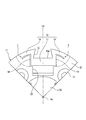
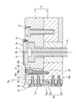
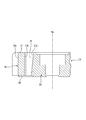
- FIG. 2 is a partially enlarged view of FIG. 2, which is a partially enlarged view in which the cartridge has been removed. It is sectional drawing A to A of FIG. It is a partial vertical sectional view of the 1st plate of the main body of the rotary tool.
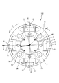
- the rotary tool 100 shown in FIGS. 1 and 2 has a plurality of cutting edges 31 on the outer peripheral side, and forms a main body 10 composed of a disk-shaped first plate 11 and a second plate 12 and a cutting edge 31. It includes a plurality of cartridges 33 to which the chip 32 is fixed, a plurality of wedges 40 for adjusting the radial positions of the cutting edges 31, and a shank portion 50 fastened to the main body 10.
- the plurality of cartridges 33 are each held in a plurality of pockets 15 provided in the main body 10.
- the rotary tool 100 rotates about its rotation axis Ra in the direction indicated by the arrow B in FIG.
- the "radial direction” and “circumferential direction” in the present specification mean the radial direction and the circumferential direction with respect to the rotation axis Ra.
- the rotary tool 100 includes four cartridges 33 that are identical to each other. Since the four cartridges 33 are the same, only one cartridge 33 will be described below. This also applies to the movable portion 16 and the wedge 40, which will be described later, of the first plate 11.
- the first plate 11 and the second plate 12 have the same outer diameter as each other, and are coaxially connected to each other by the first bolt 13.
- the shank portion 50 is connected to the second plate 12 by the second bolt 14.
- the shank portion 50 includes a known tapered portion 51 and a spindle side flange portion 52 formed so as to be mounted on a spindle (not shown) of a machine tool, and a main body side flange portion 53 attached to a main body reference surface 10a. Have. Further, inside the shank portion 50, a coolant supply path (not shown) penetrates along the rotation axis Ra.
- the cartridge 33 has a columnar shape, and as shown in FIG. 2, the cross-sectional shape thereof is formed in a substantially trapezoidal shape or a dovetail shape that fits into the pocket 15 of the first plate 11.
- the chip 32 is fixed to the short side of the substantially trapezoid by brazing.
- the cutting edge 31 of the chip 32 protrudes radially outward from the outer circumference of the main body 10.
- the insert 32 has a parallelogram when viewed in the direction of FIG. 4, and a linear cutting edge 31 is formed on one of the pair of long sides of the parallelogram.
- the cutting edge 31 is relative to the trapezoidal bottom surface of the cartridge 33 in order to obtain high parallelism between the cutting edge 31 and the rotation axis Ra. Has high parallelism.
- the pocket 15 in which the bottom surface of the trapezoid of the cartridge 33 is in contact that is, the bottom surface of the dovetail groove (hereinafter referred to as "mounting reference surface") 15a is machined so that high parallelism can be obtained with the rotation axis Ra. It is processed.
- the first plate 11 has a plurality of movable portions 16 each having a pocket 15 for holding the cartridge 33, and an immovable base portion 21 other than the movable portion 16.
- the plurality of movable portions 16 are arranged at equal angular intervals in the circumferential direction, and in the present embodiment, four are arranged at 90 degree intervals.
- the movable portion 16 is formed symmetrically with respect to the base line L0 extending in the radial direction, and is formed in the central portion 17 in which the pocket 15 is formed and in the center. It has a pair of arms 18 extending in opposite directions in the circumferential direction from the outer peripheral side of the portion 17.
- the movable portion 16 is separated from the base portion 21 by two sickle-shaped slits 19 and a wedge insertion hole 22 described later so that the two arms 18 are connected to the base portion 21 only at the C portion.
- the slit 19 and the wedge insertion hole 22 penetrate from one end face of the first plate 11 to the other end face in the direction perpendicular to the paper surface of FIG. Since the movable portion 16 is formed in this way, when a force in the radial direction acts on the central portion 17, the movable portion 16 translates in the radial direction. In this embodiment, the displacement of the arm 18 is designed not to exceed the range of elastic deformation.
- the pocket 15 formed in the central portion 17 of the movable portion 16 of the first plate 11 is formed as a dovetail groove corresponding to the cross-sectional shape of the cartridge 33.
- the pocket 15 extends from one end face of the first plate 11 to the other end face.
- a shallow recess 24 is formed in a region slightly wider than the region corresponding to the movable portion 16. The recess 24 prevents contact between the movable portion 16 and the second plate 12.
- the wedge insertion hole 22 of the first plate 11 is provided in the base portion 21 between the rotation axis Ra and the movable portion 16.
- the wedge insertion hole 22 is a substantially rectangular hole in a plan view, but when viewed in the vertical cross section of only the first plate of FIG. 5, one side is defined by the inclined wall 21a. More specifically, the wedge insertion hole 22 is not parallel to the vertical wall 17a of the central portion 17 of the movable portion 16 and the rotation axis Ra on the outer side in the radial direction parallel to the rotation axis Ra when viewed in the vertical cross section of FIG. It is formed as a space separated by an inclined wall 21a formed on a base portion 21 on the inner side in the radial direction. The inclined wall 21a is inclined so that the wedge insertion hole 22 becomes smaller toward the lower side of FIG.
- the wedge 40 has a vertical surface 40a and an inclined surface 40b that come into contact with the vertical wall 17a and the inclined wall 21a that define the wedge insertion hole 22 of the first plate 11, respectively.
- the total length of the wedge 40 is formed shorter than the thickness of the first plate 11 in the rotation axis direction so that the bottom surface of the wedge 40 does not touch the upper surface of the second plate 12.
- the vertical surface 40a of the wedge 40 is provided with a recess 40c so that only the upper portion and the lower portion thereof in FIG. 4 abut on the vertical wall 17a of the movable portion 16.
- the adjusting bolt 41 penetrates parallel to the inclined surface 40b.
- the second plate 12 is provided with a screw hole 25 into which the screw portion on the tip end side of the adjusting bolt 41 is screwed.
- the adjusting bolt 41 may be operated.
- the wedge 40 moves in the direction approaching the second plate 12, and as a result, the movable portion 16 of the first plate 11 has a radius. Move outward in the direction.
- the force acting on the vertical wall of the movable portion 16 from the wedge 40 acts evenly from the upper part and the lower part other than the recess 40c of the vertical surface 40a of the wedge 40, so that the rotation around the axis perpendicular to the paper surface of FIG.
- the rotary tool 100 of the present embodiment also includes a height adjusting portion 60 for adjusting the position of the cartridge 33 in the rotation axis direction.
- the height adjusting portion 60 is screwed into the block portion 61 inserted into the groove formed in the second plate 12 and fixed by the fourth bolt 62 and the upper end surface of the block portion 61 in FIG. 4 from the upper end surface. It is provided with an adjusting screw 63 that protrudes and contacts the bottom surface of the cartridge 33.
- the cross-sectional shape of the groove into which the block portion 61 is inserted is not shown, but the groove is formed as a dovetail groove similar to the pocket 15 of the first plate 11. Therefore, the cross-sectional shape of the block portion 61 is trapezoidal or dovetail-shaped like the cartridge 33.
- the protruding length of the adjusting screw 63 from the upper end surface of the block portion 61 can be changed by rotating the adjusting screw 63, the position of the cartridge 33 in the rotation axis direction can be adjusted.
- the rotary tool 100 of the present embodiment also includes a disc-shaped coolant distribution plate 70 in order to supply the coolant to each chip 32.
- the coolant distribution plate 70 has a coolant flow path inside.
- the coolant flow path of the coolant distribution plate 70 branches in four directions radially from the central flow path 71 and a central flow path 71 having an inlet for receiving coolant from the coolant flow path penetrating the center of the second bolt 14.
- a radial flow path 72 having an outlet facing each chip 32 is provided.
- the coolant distribution plate 70 is fixed to the first plate 11 by the fifth bolt 73.
- the parallelism between the cutting edge 31 and the rotary axis Ra is not adjusted. Therefore, the geometrical tolerances of the related components are strictly controlled so that their parallelism falls within a predetermined tolerance. Specifically, the parallelism between the bottom surface of the trapezoid of the cartridge 33 and the cutting edge 31 and the parallelism between the mounting reference surface 15a in the pocket 15 and the rotation axis Ra can be obtained with high accuracy. It is machined so that it can be used.
- the mounting reference surface 15a is a machine at a predetermined high squareness with respect to the main body reference surface 10a which is the bottom surface of the second plate 12 in a state where the first plate 11 and the second plate 12 are connected. It will be processed. Since the mounting surface of the flange portion 53 on the main body side of the shank portion 50 having a high squareness with respect to the rotating axis Ra is coupled to the main body reference surface 10a, it is highly parallel between the rotating axis Ra and the mounting reference surface 15a. You can get the degree.
- the amount of adjustment required to align the radial positions of the cutting edges 31 of the plurality of tips 32 of the rotary tool 100 used for contouring is generally 5 ⁇ m to 100 ⁇ m, whereas the embodiment of the present invention is carried out.
- the movable portion 16 of the rotary tool 100 according to the form is designed so that a maximum movement amount of 200 ⁇ m can be obtained with a margin of about twice. Since the maximum amount of movement is limited by the stress generated on the arm 18 by the movement of the movable part 16, the length or thickness of the arm 18 of the movable part 16 is changed, or the shape of the slit is adjusted so that the stress concentration is relaxed. It can be changed by changing it.
- the movement of the movable portion 16 in the above-described embodiment is based on elastic deformation.
- an embodiment in which the movement of the movable portion 16 is based on not only elastic deformation but also plastic deformation is possible.
- the rotary tool 100 has four cartridges 33, but in the present invention, the number of cartridges 33 may be 5 or more or 3 or less. In addition, an embodiment including only one cartridge 33 is also possible in the present invention.
Landscapes
- Engineering & Computer Science (AREA)
- Mechanical Engineering (AREA)
- Milling Processes (AREA)
- Cutting Tools, Boring Holders, And Turrets (AREA)
Abstract
切れ刃(31)を外周側に有する回転工具(100)であって、切れ刃(31)の形成されたチップ(32)が固定されたカートリッジ(33)と、カートリッジ(33)を保持するポケット(15)を有する本体(10)と、回転軸線(Ra)に関する切れ刃(31)の半径方向の位置を調整する楔(40)と、本体(10)に締結されたシャンク部(50)と、を具備しており、本体(10)が、基部(21)と、ポケット(15)が形成された可動部(16)であって、楔(40)からの圧力に基づいて基部(21)に対して半径方向へ並進移動するように形成された可動部(16)と、可動部(16)の半径方向内側に隣接して形成された楔挿入孔(22)とを有する。
Description
本発明は、外周面に切れ刃を有する回転工具に関する。
加工すべき穴の内径よりも細い回転工具を自転させつつ穴の中心に対して公転させることによってワークに穴あけを行う、いわゆるコンタリング(contouring)加工が従来行われている。これにより、穴あけ工具の種類の削減、及び相当に大きな径の穴あけが可能になる。ただし、コンタリング加工に回転工具を用いる場合、工具の回転軸線に対する切れ刃の平行度を維持しつつ、通常は複数ある切れ刃の半径方向の位置を揃える必要があるが、そのための調整に長い時間を要していた。
回転工具に固定される複数の切削インサートの切れ刃の半径方向の位置の調整機構に関する発明が特許文献1に記載されている。そこでは、複数の切削インサートの各々が、弾性変形可能なそれぞれの片持壁に固定され、その片持壁が、一本の調整用ボルトのくさび効果によって弾性変形させられ、結果として複数の切削インサートの半径方向の位置が一括して調整される。
特許文献1に示される調整機構によると、複数の切れ刃の半径方向の位置を個別に調整することはできず、また回転軸線に対する切れ刃の平行度が、片持壁の弾性変形に基づく前記位置調整により変化する。そのため、特許文献1に示される回転工具はコンタリング加工には不適当である。
本発明は、上記事情を鑑みてなされたものであって、切れ刃の姿勢を変化させることなく、切れ刃の半径方向の位置の調整を容易に実施できる回転工具を提供することを目的としている。
上述の目的を達成するために、本発明によれば、外周側に配置された切れ刃を有する回転工具であって、前記切れ刃の形成されたチップが固定されたカートリッジと、前記カートリッジを保持するポケットを有する本体と、該回転工具の回転軸線に関する前記切れ刃の半径方向の位置を調整する楔と、前記本体に締結されたシャンク部と、を具備しており、前記本体が、基部と、前記ポケットが形成された可動部であって、前記楔からの圧力に基づいて前記基部に対して前記半径方向へ並進移動するように形成された可動部と、前記可動部の前記半径方向内側に隣接して形成された楔挿入孔と、を有する回転工具が提供される。
本発明によると、楔挿入孔に挿入される楔の作用によって本体の可動部が半径方向に移動し、したがって可動部が保持するカートリッジのチップの切れ刃の半径方向の位置を容易に調整することが可能になる。また、可動部の移動は並進移動であるので、切れ刃の位置を調整することによって、回転軸線に対する切れ刃の平行度に変化が生じることはない。
以下、本発明の実施形態について図1~図5を参照しつつ説明する。
図1及び図2に示される回転工具100は、外周側に複数の切れ刃31を有するものであり、円盤状の第1プレート11及び第2プレート12からなる本体10と、切れ刃31の形成されたチップ32が固着された複数のカートリッジ33と、各切れ刃31の半径方向の位置を調整する複数の楔40と、本体10に締結されたシャンク部50とを具備する。複数のカートリッジ33は、本体10に設けられた複数のポケット15にそれぞれ保持されている。回転工具100は、その回転軸線Raを中心にして図2の矢印Bで示される方向に回転する。なお、本明細書における「半径方向」及び「円周方向」は、回転軸線Raに関する半径方向及び円周方向を意味する。
図1及び図2に示される回転工具100は、外周側に複数の切れ刃31を有するものであり、円盤状の第1プレート11及び第2プレート12からなる本体10と、切れ刃31の形成されたチップ32が固着された複数のカートリッジ33と、各切れ刃31の半径方向の位置を調整する複数の楔40と、本体10に締結されたシャンク部50とを具備する。複数のカートリッジ33は、本体10に設けられた複数のポケット15にそれぞれ保持されている。回転工具100は、その回転軸線Raを中心にして図2の矢印Bで示される方向に回転する。なお、本明細書における「半径方向」及び「円周方向」は、回転軸線Raに関する半径方向及び円周方向を意味する。
本実施形態では、回転工具100は、4つの互いに同一のカートリッジ33を具備する。4つのカートリッジ33は同一のものであるので、以下の説明では、1つのカートリッジ33だけが説明される。これは、第1プレート11の後述する可動部16や楔40等についても同様である。
第1プレート11と第2プレート12は互いに等しい外径を有するものであって、第1ボルト13によって同軸に互いに結合されている。第2プレート12には、第2ボルト14によってシャンク部50が結合される。シャンク部50は、工作機械の主軸(図示せず)に装着可能であるように形成された公知のテーパ部51及び主軸側フランジ部52、並びに本体基準面10aに取り付けられる本体側フランジ部53を有している。また、シャンク部50の内部では、回転軸線Raに沿って、図示しないクーラント供給路が貫通している。
カートリッジ33は、柱状のものであって、図2に示されるように、その横断面形状が、第1プレート11のポケット15に嵌合する略台形あるいは蟻ほぞ形に形成されている。前記略台形の短辺側にチップ32が、本実施形態では、ろう付けによって固定されている。カートリッジ33がポケット15に収容されて第3ボルト34によって固定されたとき、チップ32の切れ刃31は本体10の外周よりも半径方向外側に突出する。チップ32は、図4の方向で見たとき平行四辺形を呈し、その平行四辺形の一対の長辺の一方に直線状の切れ刃31が形成されている。
カートリッジ33がポケット15に収容されて固定されたとき、切れ刃31と回転軸線Raとの間の高い平行度を得るために、切れ刃31は、カートリッジ33の前記台形の底辺側の面に対して高い平行度を有している。また、カートリッジ33の前記台形の底辺側の面が接するポケット15すなわち蟻溝の底面(以下、「取付基準面」という)15aは、回転軸線Raとの間に高い平行度が得られるように機械加工されたものである。
第1プレート11は、カートリッジ33を保持するためのポケット15をそれぞれが有する複数の可動部16と、可動部16以外の不動の基部21とを有する。複数の可動部16は、図2に示されるように、円周方向に等角度間隔で配置されており、本実施形態では90度間隔で4つ配置されている。可動部16は、カートリッジ33と楔40を取り除いた図3によく示されるように、半径方向に延びる基線L0に対して対称に形成されていて、ポケット15の形成された中央部17と、中央部17の外周側から円周方向反対向きに延びる一対の腕18とを有する。可動部16は、その2つの腕18がC部においてのみ基部21に接続されるように、鎌状の2つのスリット19及び後述する楔挿入穴22により基部21から分離されている。スリット19及び楔挿入穴22は、第1プレート11の一方の端面から他方の端面まで、図3の紙面に垂直な方向へ貫通している。可動部16は、このように形成されているので、その中央部17に半径方向の力が作用すると、半径方向に並進移動する。本実施形態では、腕18の変位が弾性変形の範囲を超えないように設計されている。
第1プレート11の可動部16の中央部17に形成されるポケット15は、カートリッジ33の横断面形状に対応する蟻溝として形成されている。このようにポケット15を蟻溝として形成することにより、カートリッジ33の第3ボルト34による固定が不十分であった場合にも、回転工具100の回転中にカートリッジ33が遠心力により飛び出すといった事態を回避することが可能になる。また、ポケット15は、第1プレート11の一方の端面から他方の端面まで通して延びている。この構造により、カートリッジ33を取り付けるためのポケット15内の取付基準面15aを、回転軸線Raに対する高い平行度で加工する事が可能になる。
第1プレート11の第2プレート12に隣接する側の面には、可動部16に対応する領域よりやや広い領域に浅い凹部24が形成されている。この凹部24によって、可動部16と第2プレート12との接触が回避される。
第1プレート11の楔挿入孔22は、回転軸線Raと可動部16との間の基部21に設けられている。楔挿入孔22は、平面視ではほぼ矩形の孔であるが、図5の第1プレートだけの縦断面で見たとき、一方の側が傾斜壁21aにより画成される。より詳しくは、楔挿入孔22は、図4の縦断面で見たとき、回転軸線Raに平行な半径方向外側の、可動部16の中央部17の鉛直壁17aと、回転軸線Raに非平行な半径方向内側の基部21に形成された傾斜壁21aとにより区切られた空間として成されている。傾斜壁21aは、図5の下方に行くに従って楔挿入孔22が小さくなるように傾斜している。
楔40は、第1プレート11の楔挿入孔22を画成する鉛直壁17a及び傾斜壁21aにそれぞれ当接する鉛直面40a及び傾斜面40bを有する。楔40の全長は、その底面が第2プレート12の上面に接することがないように、第1プレート11の回転軸線方向の厚さよりも短く形成されている。楔40の鉛直面40aには、図4における、その上部と下部だけが可動部16の鉛直壁17aに当接するように凹部40cが設けられている。楔40の内部では、調整ボルト41が傾斜面40bに平行に貫通している。第2プレート12には、調整ボルト41の先端側のねじ部が螺合するねじ穴25が設けられている。
カートリッジ33に固定されたチップ32の切れ刃31の半径方向の位置を調整するためには、調整ボルト41を操作すればよい。これについて図4及び図5を参照して説明すると、調整ボルト41を締める方向に回せば、楔40は第2プレート12に近づく方向へ移動し、その結果第1プレート11の可動部16が半径方向外側に移動する。このとき、楔40から可動部16の垂直壁に作用する力は、楔40の鉛直面40aの凹部40c以外の上部と下部から均等に作用するので、図4の紙面に垂直な軸線まわりの回転モーメントが可動部16に生じることはなく、したがって、可動部16及びそれに固定されたカートリッジ33のチップ32の切れ刃31は半径方向外側に並進移動する。それゆえ、本発明の実施形態の回転工具100においては、切れ刃31の半径方向の位置を調整したことによって、回転軸線Raに対する切れ刃31の平行度が悪化することはない。
また、楔40による調整時に、回転軸線Raに平行な軸線まわりの回転モーメントも可動部16に生じないことは、図3における基線L0に関する可動部16の対称性から明らかであろう。
本実施形態の回転工具100は、カートリッジ33の回転軸線方向の位置を調整するための高さ調整部60も具備する。高さ調整部60は、第2プレート12に形成された溝に挿入されて第4ボルト62により固定されるブロック部61と、ブロック部61の、図4における上端面にねじ込まれ、上端面から突出してカートリッジ33の底面に接する調整ネジ63とを具備する。ブロック部61が挿入される溝の横断面形状は図示されないが、その溝は第1プレート11のポケット15と同様の蟻溝として形成されている。したがって、ブロック部61の横断面形状は、カートリッジ33と同様に台形又は蟻ほぞ状を呈する。
ブロック部61の上端面からの調整ネジ63の突出長さは、調整ネジ63を回転することによって変えることができるので、カートリッジ33の回転軸線方向の位置の調整が可能になる。
本実施形態の回転工具100は、クーラントを各チップ32の方へ供給するために、円板状のクーラント分配プレート70も具備する。クーラント分配プレート70は、その内部にクーラント流路を有する。クーラント分配プレート70のクーラント流路は、第2ボルト14の中心を貫通するクーラント流路からのクーラントを受け入れるための入口を有する中心流路71と、中心流路71から放射状に4方向に分岐するとともに各チップ32の方に向いた出口を有する放射状流路72を備える。クーラント分配プレート70は、第5ボルト73によって第1プレート11に固定されている。
ところで、本発明の実施形態の回転工具100は、切れ刃31と回転軸線Raとの間の平行度は調整されない。したがってその平行度が所定の公差内に入るように関連する各構成要素の幾何公差が厳しく管理されている。具体的には、カートリッジ33の前記台形の底辺側の面と切れ刃31との間の平行度、及びポケット15内の取付基準面15aと回転軸線Raとの間の平行度が高い精度で得られるように機械加工される。なお、実際的には、取付基準面15aは、第1プレート11と第2プレート12とを結合した状態で第2プレート12の底面である本体基準面10aに対して所定の高い直角度で機械加工される。本体基準面10aには、回転軸線Raに対して高い直角度を有するシャンク部50の本体側フランジ部53の取付面が結合されるので、回転軸線Raと取付基準面15aとの間の高い平行度が得られる。
コンタリング加工に用いられる回転工具100の複数のチップ32の切れ刃31の半径方向の位置を揃えるのに必要な調整量は、一般的に5μm~100μmであるのに対して、本発明の実施形態による回転工具100の可動部16は、約2倍のマージンをもって200μmの最大移動量が得られるように設計されている。最大移動量は、可動部16の移動により腕18に生じる応力により制限されるので、可動部16の腕18の長さあるいは厚さを変えたり、又は応力集中が緩和するようにスリットの形を変えたりすることによって変えることができる。
前述の実施形態における可動部16の移動は弾性変形に基づくものである。ただし、可動部16の移動が弾性変形だけでなく塑性変形も加えた変形に基づく実施形態も本発明において可能である。
前述の実施形態では、回転工具100は4つのカートリッジ33を有するものであったが、本発明においてはカートリッジ33の数は、5以上でも3以下であってもよい。また、唯1つのカートリッジ33を具備する実施形態も本発明において可能である。
10 本体
11 第1プレート
12 第2プレート
15 ポケット
16 可動部
17 中央部
18 腕
21 基部
22 楔挿入孔
31 切れ刃
32 チップ
33 カートリッジ
40 楔
50 シャンク部
100 回転工具
11 第1プレート
12 第2プレート
15 ポケット
16 可動部
17 中央部
18 腕
21 基部
22 楔挿入孔
31 切れ刃
32 チップ
33 カートリッジ
40 楔
50 シャンク部
100 回転工具
Claims (7)
- 外周側に配置された切れ刃を有する回転工具であって、
前記切れ刃の形成されたチップが固定されたカートリッジと、
前記カートリッジを保持するポケットを有する本体と、
該回転工具の回転軸線に関する前記切れ刃の半径方向の位置を調整する楔と、
前記本体に締結されたシャンク部と、
を具備しており、
前記本体が、基部と、前記ポケットが形成された可動部であって、前記楔からの圧力に基づいて前記基部に対して前記半径方向へ並進移動するように形成された可動部と、前記可動部の前記半径方向内側に隣接して形成された楔挿入孔と、を有することを特徴とした回転工具。 - 前記可動部が、前記基部に対して前記半径方向へ弾性変形により並進移動する、請求項1に記載の回転工具。
- 前記本体の前記可動部は、前記ポケットが形成された中央部と、前記中央部から円周方向反対向きに延びる一対の腕とを有し、前記一対の腕によって前記基部に接続されている、請求項1に記載の回転工具。
- 前記ポケットは、前記カートリッジを取り付けるための、前記回転軸線に平行な取付基準面を有する、請求項1に記載の回転工具。
- 前記ポケットが蟻溝として形成されており、前記カートリッジが、前記ポケットの前記蟻溝に嵌合する蟻ほぞ状に形成されている、請求項1に記載の回転工具。
- 前記本体が、前記回転軸線の一方側の第1プレートと、他方側の第2プレートであって前記第1プレートに締結された第2プレートとから構成され、
前記可動部及び前記楔挿入孔は前記第1プレートに形成され、前記シャンク部は前記第2プレートに締結される、請求項1に記載の回転工具。 - 前記カートリッジの前記回転軸線方向の位置を調整する高さ調整部をさらに具備しており、
前記高さ調整部は前記第2プレートに固定されている、請求項6に記載の回転工具。
Applications Claiming Priority (2)
| Application Number | Priority Date | Filing Date | Title |
|---|---|---|---|
| JP2019-086520 | 2019-04-26 | ||
| JP2019086520A JP6768111B1 (ja) | 2019-04-26 | 2019-04-26 | 回転工具 |
Publications (1)
| Publication Number | Publication Date |
|---|---|
| WO2020217846A1 true WO2020217846A1 (ja) | 2020-10-29 |
Family
ID=72745102
Family Applications (1)
| Application Number | Title | Priority Date | Filing Date |
|---|---|---|---|
| PCT/JP2020/013839 Ceased WO2020217846A1 (ja) | 2019-04-26 | 2020-03-26 | 回転工具 |
Country Status (2)
| Country | Link |
|---|---|
| JP (1) | JP6768111B1 (ja) |
| WO (1) | WO2020217846A1 (ja) |
Cited By (1)
| Publication number | Priority date | Publication date | Assignee | Title |
|---|---|---|---|---|
| JP7192186B1 (ja) * | 2022-01-26 | 2022-12-20 | 住友電工ハードメタル株式会社 | 切削工具 |
Families Citing this family (1)
| Publication number | Priority date | Publication date | Assignee | Title |
|---|---|---|---|---|
| CN115178761A (zh) * | 2022-07-28 | 2022-10-14 | 徐州徐工液压件有限公司 | 一种可调式粗精组合镗刀 |
Citations (2)
| Publication number | Priority date | Publication date | Assignee | Title |
|---|---|---|---|---|
| JP2003511252A (ja) * | 1999-10-12 | 2003-03-25 | ケンナメタル インコ−ポレイテツド | 切削工具における切削インサートの調整 |
| JP2013176827A (ja) * | 2012-02-29 | 2013-09-09 | Mitsubishi Materials Corp | 穴加工工具 |
-
2019
- 2019-04-26 JP JP2019086520A patent/JP6768111B1/ja active Active
-
2020
- 2020-03-26 WO PCT/JP2020/013839 patent/WO2020217846A1/ja not_active Ceased
Patent Citations (2)
| Publication number | Priority date | Publication date | Assignee | Title |
|---|---|---|---|---|
| JP2003511252A (ja) * | 1999-10-12 | 2003-03-25 | ケンナメタル インコ−ポレイテツド | 切削工具における切削インサートの調整 |
| JP2013176827A (ja) * | 2012-02-29 | 2013-09-09 | Mitsubishi Materials Corp | 穴加工工具 |
Cited By (3)
| Publication number | Priority date | Publication date | Assignee | Title |
|---|---|---|---|---|
| JP7192186B1 (ja) * | 2022-01-26 | 2022-12-20 | 住友電工ハードメタル株式会社 | 切削工具 |
| WO2023144937A1 (ja) * | 2022-01-26 | 2023-08-03 | 住友電工ハードメタル株式会社 | 切削工具 |
| US12397356B2 (en) | 2022-01-26 | 2025-08-26 | Sumitomo Electric Hardmetal Corp. | Cutting tool |
Also Published As
| Publication number | Publication date |
|---|---|
| JP2020182979A (ja) | 2020-11-12 |
| JP6768111B1 (ja) | 2020-10-14 |
Similar Documents
| Publication | Publication Date | Title |
|---|---|---|
| JP6591982B2 (ja) | スティック刃を使用する外周切削工具 | |
| KR100292963B1 (ko) | 세레이션카트리지를구비한밀링커터헤드 | |
| RU2265501C2 (ru) | Расточная шпоночная фреза | |
| US10328503B2 (en) | T-slot cutter | |
| JP3495105B2 (ja) | フライスカッタ本体 | |
| SE501915C2 (sv) | Finfräs med urtag för axiellt inställbara kassetter | |
| KR20110004866A (ko) | 공작물의 턴-턴 브로칭 또는 외부 밀링을 위한 공구 | |
| CN110325306B (zh) | 孔加工工具和用于孔加工工具的引导垫调节机构 | |
| US7402010B2 (en) | Disk-shaped or strip-shaped tool | |
| KR101238850B1 (ko) | 인서트 및 사이드 커터 | |
| JP6768111B1 (ja) | 回転工具 | |
| JP2012501861A (ja) | 調整可能切削インサートを備えた工作機械 | |
| KR20110047217A (ko) | 사이드 커터 | |
| KR20160099553A (ko) | 지지 패드를 구비한 디스크형 커터 본체를 가진 회전식 절삭 공구 | |
| BR112015010132B1 (pt) | Cabeçote de cortador de face de engrenagem cônica para fresagem e faceamento de engrenagens cônicas e hipoides e método de retificação pelo menos uma lâmina de corte posicionada em um cabeçote de cortador de face de engrenagem cônica | |
| US4456408A (en) | High speed milling cutter | |
| US10384280B2 (en) | Rotary cutting tool | |
| US3163920A (en) | Milling cutter with throwaway cutting inserts | |
| JP7131893B2 (ja) | ステップ式フライスカッタ | |
| WO2020203463A1 (ja) | 切削インサートおよび転削工具 | |
| US10549353B2 (en) | Cutting tool | |
| ZA200501242B (en) | Disk-shaped or strip-shaped tool | |
| JP2019030953A (ja) | 切削工具 | |
| CN116600923A (zh) | 用于切削加工的工具及切削刀具在该工具上的使用 | |
| JPH0847803A (ja) | スローアウェイ式切削工具 |
Legal Events
| Date | Code | Title | Description |
|---|---|---|---|
| 121 | Ep: the epo has been informed by wipo that ep was designated in this application |
Ref document number: 20794245 Country of ref document: EP Kind code of ref document: A1 |
|
| NENP | Non-entry into the national phase |
Ref country code: DE |
|
| 122 | Ep: pct application non-entry in european phase |
Ref document number: 20794245 Country of ref document: EP Kind code of ref document: A1 |