WO2020217469A1 - 通信装置 - Google Patents
通信装置 Download PDFInfo
- Publication number
- WO2020217469A1 WO2020217469A1 PCT/JP2019/017987 JP2019017987W WO2020217469A1 WO 2020217469 A1 WO2020217469 A1 WO 2020217469A1 JP 2019017987 W JP2019017987 W JP 2019017987W WO 2020217469 A1 WO2020217469 A1 WO 2020217469A1
- Authority
- WO
- WIPO (PCT)
- Prior art keywords
- gnb
- data unit
- communication device
- pdcp
- unit
- Prior art date
- Legal status (The legal status is an assumption and is not a legal conclusion. Google has not performed a legal analysis and makes no representation as to the accuracy of the status listed.)
- Ceased
Links
Images



Classifications
-
- H—ELECTRICITY
- H04—ELECTRIC COMMUNICATION TECHNIQUE
- H04W—WIRELESS COMMUNICATION NETWORKS
- H04W28/00—Network traffic management; Network resource management
- H04W28/02—Traffic management, e.g. flow control or congestion control
- H04W28/04—Error control
-
- H—ELECTRICITY
- H04—ELECTRIC COMMUNICATION TECHNIQUE
- H04L—TRANSMISSION OF DIGITAL INFORMATION, e.g. TELEGRAPHIC COMMUNICATION
- H04L47/00—Traffic control in data switching networks
- H04L47/10—Flow control; Congestion control
- H04L47/32—Flow control; Congestion control by discarding or delaying data units, e.g. packets or frames
-
- H—ELECTRICITY
- H04—ELECTRIC COMMUNICATION TECHNIQUE
- H04L—TRANSMISSION OF DIGITAL INFORMATION, e.g. TELEGRAPHIC COMMUNICATION
- H04L1/00—Arrangements for detecting or preventing errors in the information received
- H04L1/12—Arrangements for detecting or preventing errors in the information received by using return channel
- H04L1/16—Arrangements for detecting or preventing errors in the information received by using return channel in which the return channel carries supervisory signals, e.g. repetition request signals
- H04L1/18—Automatic repetition systems, e.g. Van Duuren systems
- H04L1/1829—Arrangements specially adapted for the receiver end
- H04L1/1848—Time-out mechanisms
-
- H—ELECTRICITY
- H04—ELECTRIC COMMUNICATION TECHNIQUE
- H04L—TRANSMISSION OF DIGITAL INFORMATION, e.g. TELEGRAPHIC COMMUNICATION
- H04L1/00—Arrangements for detecting or preventing errors in the information received
- H04L1/12—Arrangements for detecting or preventing errors in the information received by using return channel
- H04L1/16—Arrangements for detecting or preventing errors in the information received by using return channel in which the return channel carries supervisory signals, e.g. repetition request signals
- H04L1/18—Automatic repetition systems, e.g. Van Duuren systems
- H04L1/1867—Arrangements specially adapted for the transmitter end
- H04L1/188—Time-out mechanisms
-
- H—ELECTRICITY
- H04—ELECTRIC COMMUNICATION TECHNIQUE
- H04L—TRANSMISSION OF DIGITAL INFORMATION, e.g. TELEGRAPHIC COMMUNICATION
- H04L47/00—Traffic control in data switching networks
- H04L47/10—Flow control; Congestion control
- H04L47/28—Flow control; Congestion control in relation to timing considerations
-
- H—ELECTRICITY
- H04—ELECTRIC COMMUNICATION TECHNIQUE
- H04W—WIRELESS COMMUNICATION NETWORKS
- H04W80/00—Wireless network protocols or protocol adaptations to wireless operation
- H04W80/02—Data link layer protocols
-
- H—ELECTRICITY
- H04—ELECTRIC COMMUNICATION TECHNIQUE
- H04L—TRANSMISSION OF DIGITAL INFORMATION, e.g. TELEGRAPHIC COMMUNICATION
- H04L1/00—Arrangements for detecting or preventing errors in the information received
- H04L1/08—Arrangements for detecting or preventing errors in the information received by repeating transmission, e.g. Verdan system
Definitions
- the present invention relates to a communication device that transmits and receives a data unit of a protocol layer that handles packet data.
- LTE Long Term Evolution
- LTE-Advanced LTE-Advanced
- 5G NewRadio
- NG Next Generation
- Non-Patent Document 1 For example, in the specifications of 3GPP Release 16, support for Industrial IoT (IIoT) is being considered (Non-Patent Document 1). When supporting IIoT, it is essential to realize high-reliability and low-latency communication (URLLC: Ultra-Reliable and Low Latency Communications), but in the above-mentioned examination, packet data convergence that ensures high reliability -Includes improved efficiency of packet (data unit) duplicate transmission control (PDCP duplication) at the protocol layer (PDCP).
- URLLC Ultra-Reliable and Low Latency Communications
- Non-Patent Document 2 a node having an entity of a layer below the control layer (RLC) is instructed to be destroyed one by one (Non-Patent Document 2).
- Non-Patent Document 3 when PDCP duplication is applied, the frequency of such instructions increases, so it is being studied to improve efficiency while using a discard timer.
- gNB-CU Central Unit
- gNB-DU Distributed Unit
- time synchronization is generally not achieved between gNB-CU and gNB-DU. Therefore, there is a possibility that the data unit discard operation may be misrecognized between the nodes.
- a data unit determined to be discarded due to the expiration of the discard timer may actually be transmitted to the UE, or conversely, a data unit determined to be transmitted may actually be discarded. obtain.
- an object of the present invention is to provide a communication device capable of more reliably controlling the destruction of a data unit of the packet data convergence protocol layer.
- One aspect of the present invention is a communication device (for example, gNB-CU110), which is a transmission unit (data unit transmission unit) that transmits a data unit of a protocol layer that handles packet data to a destination communication device (gNB-DU120). 115), a receiving unit (data unit receiving unit 117) that receives the data unit of the protocol layer from the destination communication device, and a control unit that controls a discard timer of the data unit transmitted to the destination communication device. (Control unit 119) is provided, the control unit determines a delay amount between the communication device and the destination communication device, and applies a timer value corresponding to the determined delay amount to the discard timer.
- One aspect of the present invention is a communication device (for example, gNB-CU110), which includes a transmission unit (data unit transmission unit 115) that transmits a data unit of a protocol layer that handles packet data to a destination communication device, and the above.
- a receiving unit data unit receiving unit 117
- control unit control unit 119
- the control unit executes time synchronization with the destination communication device, and instructs the destination communication device to discard the data unit in response to the expiration of the discard timer.
- One aspect of the present invention is a communication device (for example, gNB-DU120), which includes a transmission unit (data unit transmission unit 125) that transmits a data unit of a protocol layer that handles packet data to a destination communication device, and the above.
- a receiving unit data unit receiving unit 127) that receives a data unit of the protocol layer from the destination communication device, and a control unit (control unit 129) that controls a discard timer of the data unit transmitted to the destination communication device.
- the control unit notifies the destination communication device that the data unit has been destroyed.
- FIG. 1 is an overall schematic configuration diagram of the wireless communication system 10.
- FIG. 2 is a diagram showing a protocol stack of gNB100 and UE200.
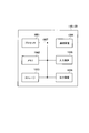
- FIG. 3 is a functional block configuration diagram of gNB-CU110.
- FIG. 4 is a functional block configuration diagram of gNB-DU120.
- FIG. 5 is an explanatory diagram of the relationship between the delay amount between the PDCP hosting node, the Corresponding node, and the UE 200 and the timer value applied to the timer for discarding the data unit.
- FIG. 6 is a diagram showing a data unit discard operation flow (operation example 1) in the PDCP layer.
- FIG. 7 is a diagram showing a data unit discard operation flow (operation example 2) in the PDCP layer.
- FIG. 8 is a diagram showing a data unit discard operation flow (operation example 3) in the PDCP layer.
- FIG. 9 is a diagram showing an example of the hardware configuration of gNB-CU110 and gNB-DU120.
- FIG. 1 is an overall schematic configuration diagram of the wireless communication system 10 according to the present embodiment.
- the wireless communication system 10 is a wireless communication system according to 5G (NR).
- the wireless communication system 10 includes the Next Generation-Radio Access Network 20 (hereinafter, NG-RAN20) and the user terminal 200 (hereinafter, UE200).
- NG-RAN20 includes a radio base station 100 (hereinafter, gNB100).
- gNB100 radio base station 100
- the specific configuration of the wireless communication system 10 including the number of gNBs and UEs is not limited to the example shown in FIG.
- the NG-RAN20 actually includes multiple NG-RANNodes, specifically gNB (or ng-eNB), and is connected to a core network (5GC, not shown) according to 5G.
- gNB or ng-eNB
- 5GC core network
- the gNB100 is a 5G-compliant wireless base station that executes wireless communication with UE200 (and UE200B, the same applies hereinafter) according to 5G.
- the gNB 100 is composed of a Central Unit (gNB-CU) and a Distributed Unit (gNB-DU), as will be described later.
- gNB-CU Central Unit
- gNB-DU Distributed Unit
- the gNB100 and UE200 include Massive MIMO, which generates a more directional beam by controlling radio signals transmitted from multiple antenna elements, carrier aggregation (CA) using multiple component carriers (CC), and multiple carriers. It is possible to support dual connectivity (DC) that simultaneously transmits component carriers between the NG-RAN Node and UE.
- Massive MIMO which generates a more directional beam by controlling radio signals transmitted from multiple antenna elements, carrier aggregation (CA) using multiple component carriers (CC), and multiple carriers.
- CA carrier aggregation
- CC component carriers
- DC dual connectivity
- FIG. 2 shows the protocol stack of gNB100 and UE200.
- the gNB 100 includes a gNB-Central Unit 120 (hereinafter, gNB-CU110) and a gNB-Distributed Unit 110 (hereinafter, gNB-DU120).
- gNB-CU110 gNB-Central Unit 120
- gNB-DU120 gNB-Distributed Unit 110
- the gNB-CU110 is a logical node that provides a packet data convergence protocol layer (PDCP) and a radio resource control layer (RRC).
- PDCP packet data convergence protocol layer
- RRC radio resource control layer
- SDAP Service Data Adaptation Protocol Layer
- the gNB-DU120 provides a lower layer, specifically, a physical layer (L1) and a radio unit (RF), a medium access control layer (MAC), and a radio link control layer (RLC) (host).
- L1 physical layer
- RF radio unit
- MAC medium access control layer
- RLC radio link control layer
- GNB-DU120 supports one or more cells. One cell is supported by only one gNB-DU.
- the gNB-DU120 terminates the F1 interface with the gNB-CU110.
- Such a form of separation between CU and DU is called Higher Layer Split (HLS).
- the gNB-CU110 has a PDCP layer and constitutes a PDCP hosting node.
- gNB-DU120 has a layer below the RLC layer and constitutes a Corresponding node.
- the gNB-CU110 can form a communication device, and the gNB-DU120 can form a destination communication device. Further, gNB-DU120 may constitute a communication device, and gNB-CU110 may constitute a destination communication device.
- the gNB-CU110 controls the operation of one or more gNB-DU120s.
- the gNB-CU110 terminates the F1 interface with the gNB-DU120.
- UE200 has layers such as RF, L1, MAC, RLC, RDCP, and RRC.
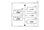
- FIG. 3 is a functional block configuration diagram of gNB-CU110. As shown in FIG. 3, the gNB-CU110 includes an X2 IF unit 111, an F1 IF unit 113, a data unit transmission unit 115, a data unit reception unit 117, and a control unit 119.
- the X2 IF unit 111 provides an interface for realizing communication with RAN nodes that make up the NG-RAN20, such as other gNBs. Specifically, the X2 IF unit 111 is an interface (X2) that directly connects to the RAN node. Various data sent and received by the UE200 is relayed to the NG-RAN20 via the X2 IF unit 111.
- the F1 IF unit 113 provides an interface for realizing communication between the gNB-CU110 and the gNB-DU120.
- the F1 IF unit 113 is an interface (F1) that directly connects the gNB-CU110 and the gNB-DU120.
- Various data sent and received by the UE200 are relayed to the gNB-DU120 via the F1 IF unit 113.
- the data unit transmission unit 115 executes processing related to data unit transmission in a plurality of layers. Specifically, the data unit transmission unit 115 transmits the data unit of the protocol layer that handles packet data, specifically, the PDCP layer to the gNB-DU120.
- the data unit referred to here may be a Protocol Data Unit (PDU) including the header of the layer, or a Service Data Unit (SDU) not including the header.
- PDU Protocol Data Unit
- SDU Service Data Unit
- the data unit transmission unit 115 also executes data unit transmission not only in the PDCP layer but also in other layers (SDAP, etc.).
- the data unit transmission unit 115 executes duplicate transmission of the data unit (which may be rephrased as a packet) in the PDCP layer to a plurality of destinations, so-called PDCP duplication.
- PDCP duplication is specified in 3GPP TS38.323.
- the sending PDCP entity can behave as follows:
- the data unit transmission unit 115 enables PDCP replication based on the control of the control unit 119 (the same applies hereinafter).
- SRB Signaling Radio Bearer
- DRB DataRadioBearer
- the sending PDCP entity can operate as follows. Specifically, if one of the two related AM (Acknowledged Mode) RLC entities confirms that the PDCP data PDU has been successfully delivered, the other will discard the duplicate PDCP data PDU. Instruct the AM RLC entity.
- the data unit transmitter 115 instructs the secondary RLC entity to discard all duplicate PDCP data PDUs.
- the data unit transmission unit 115 constitutes a transmission unit that transmits a protocol layer (PDCP) data unit that handles packet data to a destination communication device (gNB-DU120).
- PDCP protocol layer
- the data unit receiving unit 117 is a functional block paired with the data unit transmitting unit 115, and executes processing related to data unit reception in a plurality of layers. Specifically, the data unit receiving unit 117 receives the data unit of the PDCP layer from the gNB-DU120 via the lower layer.
- the data unit receiving unit 117 constitutes a receiving unit that receives the data unit of the protocol layer (PDCP) from the destination communication device (gNB-DU120).
- PDCP protocol layer
- the control unit 119 controls each functional block constituting the gNB-CU110.
- the control unit 119 controls the timer for discarding the data unit transmitted to the gNB-DU120.
- control unit 119 determines the amount of delay between the gNB-CU110 (communication device) and the gNB-DU120 (destination communication device).
- control unit 119 acquires the delay amount by the following method, and determines the delay amount used for controlling the discard timer based on the acquired delay amount. That is, the acquired delay amount and the determined delay amount do not have to match.
- the delay amount can typically mean the delay time due to the transmission of the data unit between the gNB-CU110 and the gNB-DU120, but is not necessarily limited to such a delay time.
- the delay amount may be a simple delay time (for example, milliseconds), may be a pair of transmission time and reception time, or may indicate only a difference from some reference time.
- the control unit 119 applies the timer value according to the determined delay amount to the timer for discarding the data unit of the PDCP layer. Specifically, the control unit 119 sets the time until the discard timer expires as a timer value based on the acquired numerical value indicating the delay amount and the reference value of the time set in the discard timer. To do.
- control unit 119 may notify the gNB-DU120 (destination communication device) of the value obtained by subtracting the delay amount from the reference value.
- control unit 119 may execute time synchronization with the gNB-DU120. Specifically, the control unit 119 periodically executes a time synchronization process so that the gNB-CU110 and the gNB-DU120 can be synchronized with a reference clock having an accuracy of a predetermined level (stratum) or higher. Alternatively, a time synchronization protocol (Network Time Protocol (NTP), etc.) may be used so that the times set in the gNB-CU 110 and the gNB-DU 120 are within a time difference that does not cause any operational problem.
- NTP Network Time Protocol
- control unit 119 instructs the gNB-DU120 to destroy the data unit of the PDCP layer in response to the expiration of the discard timer.
- FIG. 4 is a functional block configuration diagram of gNB-DU120.
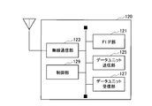
- the gNB-DU120 includes an F1 IF unit 121, a wireless communication unit 123, a data unit transmission unit 125, a data unit reception unit 127, and a control unit 129.
- the same parts as gNB-CU110 will be omitted as appropriate.
- the F1 IF unit 121 provides an interface for realizing communication between the gNB-CU 110 and the gNB-DU 120, similar to the F1 IF unit 113 of the gNB-CU110.
- the wireless communication unit 123 executes wireless communication with the UE 200. Specifically, the wireless communication unit 123 executes wireless communication with the UE 200 according to the 5G specifications. As mentioned above, UE200 can support Massive MIMO, Carrier Aggregation (CA), Dual Connectivity (DC), and the like.
- Massive MIMO Massive MIMO, Carrier Aggregation (CA), Dual Connectivity (DC), and the like.
- the data unit transmission unit 125 and the data unit reception unit 127 face the data unit transmission unit 115 and the data unit reception unit 117 of the gNB-CU110, and execute processing related to transmission and reception of the data unit in a plurality of layers.
- the gNB-CU 110 and the gNB-DU 120 are functionally separated according to the HLS (see FIG. 2), so that the gNB-DU 120 is a data unit in the layer below the RLC layer. Execute the process.
- the control unit 129 has almost the same function as the control unit 119 of the gNB-CU110.
- the control unit 129 receives the reference value of the time set in the discard timer from gNB-CU110, and subtracts the delay amount from the received reference value for discarding that gNB-DU120 has. It may be applied as a timer value to the timer.
- the gNB-CU110 explicitly or implicitly instructs the data unit to be destroyed, the gNB-DU120 does not necessarily have to have a discard timer.
- control unit 129 may notify the gNB-CU110 that the data unit has been destroyed.
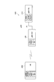
- FIG. 5 is an explanatory diagram of the relationship between the amount of delay between the PDCP hosting node, Corresponding node, and UE200 and the timer value applied to the timer for discarding the data unit.
- the PDCP hosting node shown in FIG. 5 is a node having a PDCP entity
- the Corresponding node is a node having an entity of a layer below RLC.
- gNB-CU110 corresponds to PDCP hosting node and gNB-DU120 corresponds to Corresponding node, but it is not necessarily limited to gNB-CU and gNB-DU.
- a delay occurs in each section (D1 to D4 in the figure). Specifically, in the PDCP hosting node, a delay (D1) due to queuing of the data unit occurs.
- the PDCP hosting node to the Corresponding node are connected via the F1 interface, a certain propagation delay (D2) occurs, and a device such as a router intervenes in the middle.
- D2 propagation delay
- the delay time can also fluctuate.
- PDCP hosting node acquires the delay amount D between PDCP hosting node and Corresponding node (the specific acquisition method will be described later).
- the Corresponding node In order for the Corresponding node to discard the data unit (PDCP PDU / SDU) at the appropriate timing expected by the PDCP hosting node, the PDCP hosting node subtracts the delay amount D from the reference value S of the time set in the discard timer TM. The value is set to the timer value T, and the timer value T is set to the discard timer TM.
- the PDCP hosting node starts the discard timer TM based on the set timer value T, and when the discard timer TM expires, instructs the Corresponding node to destroy the corresponding data unit (or, as described above, Corresponding). node has a discard timer TM and may discard the corresponding data unit).
- operation examples 1 to 3 are basically intended to operate in the downlink (DL) direction, but are not necessarily limited to DL depending on the layer configuration of the PDCP hosting node and Corresponding node. Instead, it may be operated in the upstream (UL).
- DL downlink
- UL upstream
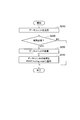
- FIG. 6 shows a data unit discard operation flow (operation example 1) in the PDCP layer.
- the PDCP hosting node for example, gNB-CU110
- the PDCP hosting node acquires the delay amount D by any of the following methods.
- the PDCP hosting node obtains the delay amount D repeatedly, periodically or irregularly, defining the distribution of the delay amount D or the range of values of the delay amount D, and the actual The value of the delay amount D may be determined.
- the Corresponding node notifies the delay amount or similar information for each variable element of the delay amount D (for example, buffering time, processing time, propagation delay or jitter of the data unit in the PDCP hosting node). May be good.
- the unit of notification may be notified for each packet (or data unit), for each wireless bearer, RLC bearer, RLC entity, logical channel (LCH), or for each packet (or data unit) type (for example, data). It may be notified in units of PDU, control PDU).
- the PDCP hosting node may notify the Corresponding node of the timer value T obtained by subtracting the delay amount D.
- the Corresponding node may start the discard timer of the Corresponding node by subtracting the delay amount D from the timer value (reference value S) notified from the PDCP hosting node.
- PDCP hosting node sets the timer value T according to the acquired delay amount D (S20) and activates the discard timer TM (S30).
- the PDCP hosting node determines whether or not the time according to the timer value T set in the discard timer TM has expired (S40).
- the PDCP hosting node discards the corresponding data unit (S50). Specifically, as described above, the PDCP hosting node instructs the Corresponding node to destroy the data unit.
- FIG. 7 shows a data unit discard operation flow (operation example 2) in the PDCP layer.
- time synchronization is executed between the PDCP hosting node and the Corresponding node.
- PDCP hosting node and Corresponding node execute time synchronization between nodes (S110). Specifically, each of the PDCP hosting node and the Corresponding node operates so as to synchronize with a highly accurate reference clock. Alternatively, the PDCP hosting node and the Corresponding node may be synchronized using a protocol for time synchronization or the like.
- the PDCP hosting node activates the discard timer (S120).
- the reference value S may be used as the timer value.
- S130 and S140 The processing of S130 and S140 is the same as S40 and S50 of operation example 1, but PDCP hosting node simply uses the time (absolute time) synchronized between the nodes to discard the data unit to Corresponding node. Instruct.
- FIG. 8 shows a data unit discard operation flow (operation example 3) in the PDCP layer.
- the Corresponding node that received the data unit explicitly notifies the PDCP hosting node that the data unit has been destroyed.
- the Corresponding node receives the data unit transmitted by the PDCP hosting node (S210).
- Corresponding node determines whether it is necessary to destroy the data unit (S220).
- the individual destruction may be based on the expiration of the destruction timer, or may be based on other reasons.
- the Corresponding node determines that it is necessary to destroy the data unit, it destroys the buffered data unit (S230).
- Corresponding node notifies PDCP hosting node that the data unit has been destroyed (S240). That is, when the Corresponding node destroys the buffered data unit, the PDCP hosting node is explicitly notified that the data unit has been destroyed.
- the Corresponding node may notify the PDCP hosting node of information that can determine which data unit (or packet) has been discarded.
- the PDCP hosting node may discard the data unit.
- the PDCP hosting node can operate in the same manner as the Corresponding node of the above-mentioned operation example 1 or operation example 2.
- the Corresponding node may notify the delay time (for example, the delay within the Corresponding node, the delay between nodes, the delay in the Uu interface with the UE 200, etc.) in each delay element (U1 to U4 in FIG. 5).
- the delay time for example, the delay within the Corresponding node, the delay between nodes, the delay in the Uu interface with the UE 200, etc.
- the Corresponding node or UE200 may notify the PDCP hosting node of information including a time stamp at the time of transmission of the data unit.
- the Corresponding node may discard the data unit even in the upward direction. In this case, it is preferable that the Corresponding node notifies the PDCP hosting node which data unit (or packet) has been discarded.
- the following action / effect can be obtained.
- the gNB-CU110 (PDCP hosting node) determines the delay amount between the gNB-CU110 and the gNB-DU120, and applies a timer value according to the determined delay amount to the discard timer. Therefore, it is possible to instruct gNB-DU120 to destroy the data unit in the PDCP layer at an appropriate timing in consideration of the delay amount.
- the gNB-CU110 can notify the gNB-DU120 of a value obtained by subtracting the delay amount from the reference value of the time set in the discard timer.
- the gNB-DU120 can apply a value obtained by subtracting the delay amount from the reference value received from the gNB-CU110 as the timer value.
- the gNB-CU110 and gNB-DU120 can execute time synchronization. Specifically, as described above, the time set for gNB-CU110 and gNB-DU120 by synchronizing with a reference clock having an accuracy of a predetermined level (stratum) or higher, or by using a protocol for time synchronization or the like. However, the time difference is such that there is no problem in operation.
- the gNB-DU120 can notify the gNB-CU110 that the PDCP data unit has been destroyed. This ensures that the gNB-CU110 has destroyed the PDCP data unit even if there is a certain amount of delay and the gNB-DU120 cannot be instructed to destroy the PDCP data unit at the appropriate time. Can be recognized by.
- gNB-CU110 and gNB-DU120 having an HLS configuration have been described as examples of PDCP hosting node and Corresponding node, but PDCP hosting node and Corresponding node are gNB-CU110. Is not limited to the combination of and gNB-DU120.
- PDCP hosting node and Corresponding node in the case of dual connectivity, there is a certain amount of delay between the node having the PDCP entity (gNB) and the node having the entity of the layer below RLC (eNB). The same can be applied when destroying a data unit.
- gNB PDCP entity
- eNB entity of the layer below RLC
- the PDCP data unit has been described as an example, but the protocol that handles packet data such as IP is not necessarily limited to PDCP.
- each functional block may be realized by using one physically or logically connected device, or physically or logically. Two or more logically separated devices may be directly or indirectly connected (for example, by wire or wireless) and realized by using these plurality of devices.
- the functional block may be realized by using the above 1 It may be realized by combining software with one device or the plurality of devices described above.
- Functions include judgment, decision, judgment, calculation, calculation, processing, derivation, investigation, search, confirmation, reception, transmission, output, access, solution, selection, selection, establishment, comparison, assumption, expectation, and assumption.
- broadcasting notifying, communicating, forwarding, configuring, reconfiguring, allocating, mapping, assigning, etc., but only these.
- a functional block that makes transmission function is called a transmitting unit or a transmitter.
- the method of realizing each is not particularly limited.
- FIG. 9 is a diagram showing an example of the hardware configuration of the device.
- the device may be configured as a computer device including a processor 1001, a memory 1002, a storage 1003, a communication device 1004, an input device 1005, an output device 1006, a bus 1007, and the like.
- the word “device” can be read as a circuit, device, unit, etc.
- the hardware configuration of the device may be configured to include one or more of each of the devices shown in the figure, or may be configured not to include some of the devices.
- Each functional block of the device (see FIGS. 3 and 4) is realized by any hardware element of the computer device or a combination of the hardware elements.
- the processor 1001 performs the calculation, controls the communication by the communication device 1004, and the memory. It is realized by controlling at least one of reading and writing of data in 1002 and storage 1003.
- Processor 1001 operates, for example, an operating system to control the entire computer.
- the processor 1001 may be composed of a central processing unit (CPU) including an interface with peripheral devices, a control device, an arithmetic unit, registers, and the like.
- CPU central processing unit
- the processor 1001 reads a program (program code), a software module, data, etc. from at least one of the storage 1003 and the communication device 1004 into the memory 1002, and executes various processes according to these.
- a program program code
- a program that causes a computer to execute at least a part of the operations described in the above-described embodiment is used.
- the various processes described above may be executed by one processor 1001 or may be executed simultaneously or sequentially by two or more processors 1001.
- Processor 1001 may be implemented by one or more chips.
- the program may be transmitted from the network via a telecommunication line.
- the memory 1002 is a computer-readable recording medium, and is composed of at least one of, for example, ReadOnlyMemory (ROM), ErasableProgrammableROM (EPROM), Electrically ErasableProgrammableROM (EEPROM), RandomAccessMemory (RAM), and the like. May be done.
- the memory 1002 may be called a register, a cache, a main memory (main storage device), or the like.
- the memory 1002 can store a program (program code), a software module, or the like that can execute the method according to the embodiment of the present disclosure.
- the storage 1003 is a computer-readable recording medium, for example, an optical disk such as a Compact Disc ROM (CD-ROM), a hard disk drive, a flexible disk, a photomagnetic disk (for example, a compact disk, a digital versatile disk, a Blu-ray). It may consist of at least one (registered trademark) disk), smart card, flash memory (eg, card, stick, key drive), floppy (registered trademark) disk, magnetic strip, and the like.
- Storage 1003 may be referred to as auxiliary storage.
- the recording medium described above may be, for example, a database, server or other suitable medium containing at least one of memory 1002 and storage 1003.
- the communication device 1004 is hardware (transmission / reception device) for communicating between computers via at least one of a wired network and a wireless network, and is also referred to as, for example, a network device, a network controller, a network card, a communication module, or the like.
- Communication device 1004 includes, for example, a high frequency switch, a duplexer, a filter, a frequency synthesizer, etc. in order to realize at least one of frequency division duplex (FDD) and time division duplex (TDD). It may be composed of.
- FDD frequency division duplex
- TDD time division duplex
- the input device 1005 is an input device (for example, keyboard, mouse, microphone, switch, button, sensor, etc.) that accepts input from the outside.
- the output device 1006 is an output device (for example, a display, a speaker, an LED lamp, etc.) that outputs to the outside.
- the input device 1005 and the output device 1006 may have an integrated configuration (for example, a touch panel).
- each device such as the processor 1001 and the memory 1002 is connected by the bus 1007 for communicating information.
- the bus 1007 may be configured by using a single bus, or may be configured by using a different bus for each device.
- the device includes hardware such as a microprocessor, a digital signal processor (Digital Signal Processor: DSP), an Application Specific Integrated Circuit (ASIC), a Programmable Logic Device (PLD), and a Field Programmable Gate Array (FPGA).
- the hardware may implement some or all of each functional block.
- processor 1001 may be implemented using at least one of these hardware.
- information notification includes physical layer signaling (for example, Downlink Control Information (DCI), Uplink Control Information (UCI), upper layer signaling (eg, RRC signaling, Medium Access Control (MAC) signaling, broadcast information (Master Information Block)). (MIB), System Information Block (SIB)), other signals or combinations thereof.
- DCI Downlink Control Information
- UCI Uplink Control Information
- RRC signaling may also be referred to as an RRC message, for example, RRC Connection Setup. ) Message, RRC Connection Reconfiguration message, etc. may be used.
- LTE Long Term Evolution
- LTE-A LTE-Advanced
- SUPER 3G IMT-Advanced
- 4th generation mobile communication system 4th generation mobile communication system
- 5G 5 th generation mobile communication system
- Future Radio Access FAA
- New Radio NR
- W-CDMA registered trademark
- GSM registered trademark
- CDMA2000 Code Division Multiple Access 2000
- UMB Ultra Mobile Broadband
- IEEE 802.11 Wi-Fi (registered trademark))
- IEEE 802.16 WiMAX®
- IEEE 802.20 Ultra-WideBand (UWB), Bluetooth®
- other systems that utilize suitable systems and at least next-generation systems extended based on them. It may be applied to one.
- a plurality of systems may be applied in combination (for example, a combination of at least one of LTE and LTE-A and 5G).
- the specific operation performed by the base station in the present disclosure may be performed by its upper node (upper node).
- various operations performed for communication with a terminal are performed by the base station and other network nodes other than the base station (for example, MME or). It is clear that it can be done by at least one of (but not limited to, S-GW, etc.).
- S-GW network node
- the case where there is one network node other than the base station is illustrated above, it may be a combination of a plurality of other network nodes (for example, MME and S-GW).
- Information and signals can be output from the upper layer (or lower layer) to the lower layer (or upper layer).
- Input / output may be performed via a plurality of network nodes.
- the input / output information may be stored in a specific location (for example, memory) or may be managed using a management table.
- the input / output information can be overwritten, updated, or added.
- the output information may be deleted.
- the input information may be transmitted to another device.
- the determination may be made by a value represented by 1 bit (0 or 1), by a boolean value (Boolean: true or false), or by comparing numerical values (for example, a predetermined value). It may be done by comparison with the value).
- the notification of predetermined information (for example, the notification of "being X") is not limited to the explicit one, but is performed implicitly (for example, the notification of the predetermined information is not performed). May be good.
- Software is an instruction, instruction set, code, code segment, program code, program, subprogram, software module, whether called software, firmware, middleware, microcode, hardware description language, or another name.
- Applications, software applications, software packages, routines, subroutines, objects, executable files, execution threads, procedures, functions, etc. should be broadly interpreted to mean.
- software, instructions, information, etc. may be transmitted and received via a transmission medium.
- a transmission medium For example, a website, where the software uses at least one of wired technology (coaxial cable, fiber optic cable, twist pair, Digital Subscriber Line (DSL), etc.) and wireless technology (infrared, microwave, etc.).
- wired technology coaxial cable, fiber optic cable, twist pair, Digital Subscriber Line (DSL), etc.
- wireless technology infrared, microwave, etc.
- the information, signals, etc. described in this disclosure may be represented using any of a variety of different techniques.
- data, instructions, commands, information, signals, bits, symbols, chips, etc. that may be referred to throughout the above description are voltages, currents, electromagnetic waves, magnetic fields or magnetic particles, light fields or photons, or any of these. It may be represented by a combination of.
- a channel and a symbol may be a signal (signaling).
- the signal may be a message.
- the component carrier (CC) may be referred to as a carrier frequency, a cell, a frequency carrier, or the like.
- system and “network” used in this disclosure are used interchangeably.
- the information, parameters, etc. described in the present disclosure may be expressed using absolute values, relative values from predetermined values, or using other corresponding information. It may be represented.
- the radio resource may be one indicated by an index.
- Base Station BS
- Wireless Base Station Wireless Base Station
- NodeB NodeB
- eNodeB eNodeB
- gNodeB gNodeB
- Base stations are sometimes referred to by terms such as macrocells, small cells, femtocells, and picocells.
- the base station can accommodate one or more (for example, three) cells (also called sectors). When a base station accommodates multiple cells, the entire coverage area of the base station can be divided into multiple smaller areas, each smaller area being a base station subsystem (eg, a small indoor base station (Remote Radio)). Communication services can also be provided by Head: RRH).
- a base station subsystem eg, a small indoor base station (Remote Radio)
- Communication services can also be provided by Head: RRH).
- cell refers to a base station that provides communication services in this coverage, and part or all of the coverage area of at least one of the base station subsystems.
- MS mobile station
- UE user equipment
- terminal terminal
- Mobile stations can be subscriber stations, mobile units, subscriber units, wireless units, remote units, mobile devices, wireless devices, wireless communication devices, remote devices, mobile subscriber stations, access terminals, mobile terminals, wireless, depending on the trader. It may also be referred to as a terminal, remote terminal, handset, user agent, mobile client, client, or some other suitable term.
- At least one of the base station and the mobile station may be called a transmitting device, a receiving device, a communication device, or the like.
- At least one of the base station and the mobile station may be a device mounted on the mobile body, the mobile body itself, or the like.
- the moving body may be a vehicle (eg, car, airplane, etc.), an unmanned moving body (eg, drone, self-driving car, etc.), or a robot (manned or unmanned). ) May be.
- at least one of the base station and the mobile station includes a device that does not necessarily move during communication operation.
- at least one of a base station and a mobile station may be an Internet of Things (IoT) device such as a sensor.
- IoT Internet of Things
- the base station in the present disclosure may be read as a mobile station (user terminal, the same applies hereinafter).
- communication between a base station and a mobile station has been replaced with communication between a plurality of mobile stations (for example, it may be called Device-to-Device (D2D), Vehicle-to-Everything (V2X), etc.).
- D2D Device-to-Device
- V2X Vehicle-to-Everything
- Each aspect / embodiment of the present disclosure may be applied to the configuration.
- the mobile station may have the function of the base station.
- words such as "up” and “down” may be read as words corresponding to inter-terminal communication (for example, "side").
- the uplink, downlink, and the like may be read as side channels.
- the mobile station in the present disclosure may be read as a base station.
- the base station may have the functions of the mobile station.
- connection means any direct or indirect connection or connection between two or more elements, and each other. It can include the presence of one or more intermediate elements between two “connected” or “combined” elements.
- the connection or connection between the elements may be physical, logical, or a combination thereof.
- connection may be read as "access”.
- the two elements use at least one of one or more wires, cables and printed electrical connections, and, as some non-limiting and non-comprehensive examples, the radio frequency domain.
- Electromagnetic energies with wavelengths in the microwave and light (both visible and invisible) regions, etc. can be considered to be “connected” or “coupled” to each other.
- the reference signal can also be abbreviated as Reference Signal (RS), and may be called a pilot (Pilot) depending on the applicable standard.
- RS Reference Signal
- Pilot pilot
- references to elements using designations such as “first”, “second” as used in this disclosure does not generally limit the quantity or order of those elements. These designations can be used in the present disclosure as a convenient way to distinguish between two or more elements. Thus, references to the first and second elements do not mean that only two elements can be adopted there, or that the first element must somehow precede the second element.
- the term "A and B are different” may mean “A and B are different from each other”.
- the term may mean that "A and B are different from C”.
- Terms such as “separate” and “combined” may be interpreted in the same way as “different”.
- Radio communication system 20 NG-RAN 100 gNB 110 gNB-CU 111 X2 IF section 113 F1 IF section 115 Data unit transmitter 117 Data unit receiver 119 Control 120 gNB-DU 121 F1 IF unit 123 Wireless communication unit 125 Data unit transmitter 127 Data unit receiver 129 Control unit 200 UE D Delay amount S Reference value T Timer value 1001 Processor 1002 Memory 1003 Storage 1004 Communication device 1005 Input device 1006 Output device 1007 Bus
Landscapes
- Engineering & Computer Science (AREA)
- Computer Networks & Wireless Communication (AREA)
- Signal Processing (AREA)
- Mobile Radio Communication Systems (AREA)
Abstract
gNB-CU(110)は、パケット・データを取り扱うプロトコル・レイヤのデータユニットをgNB-DU(120)に送信する送信部(115)と、当該プロトコル・レイヤのデータユニットをgNB-DU(120)から受信する受信部(117)と、gNB-DU(120)に送信されるデータユニットの破棄用タイマを制御する制御部(119)とを備える。制御部(119)は、gNB-CU(110)とgNB-DU(120)との遅延量を決定し、決定した遅延量に応じたタイマ値を破棄用タイマに適用する。
Description
本発明は、パケット・データを取り扱うプロトコル・レイヤのデータユニットを送受信する通信装置に関する。
3rd Generation Partnership Project(3GPP)は、Long Term Evolution(LTE)を仕様化し、LTEのさらなる高速化を目的としてLTE-Advanced(以下、LTE-Advancedを含めてLTEという)を仕様化している。また、3GPPでは、さらに、5G、New Radio(NR)、或いはNext Generation(NG)などと呼ばれるLTEの後継システムの仕様が検討されている。
例えば、3GPP Release 16の仕様では、Industrial IoT(IIoT)への対応が検討されている(非特許文献1)。IIoTに対応する場合、高信頼・低遅延通信(URLLC:Ultra-Reliable and Low Latency Communications)の実現が不可欠であるが、上述した検討の中には、高信頼性を確保するパケット・データ・コンバージェンス・プロトコル・レイヤ(PDCP)でのパケット(データユニット)の重複送信制御(PDCP duplication)の効率改善が含まれている。
3GPP Release 15の仕様では、データユニット(具体的には、PDCP SDU (Service Data Unit))破棄用タイマ(discard timer)が満了した場合、PDCPエンティティを有するノード(PDCP hosting nodeという)が、無線リンク制御レイヤ(RLC)以下のレイヤのエンティティを有するノード(Corresponding nodeという)に対して、破棄を逐一指示することが規定されている(非特許文献2)。
また、PDCP duplicationが適用されると、このような指示の頻度が高まるため、破棄用タイマを用いつつ、効率改善を実現することが検討されている(非特許文献3)。
"New WID: Support of NR Industrial Internet of Things (IoT)", RP-190728, 3GPP TSG RAN Meeting #83, 3GPP, 2019年3月
3GPP TS 38.425 V15.4.0, 3rd Generation Partnership Project; Technical Specification Group Radio Access Network; NG-RAN; NR user plane protocol(Release 15), 3GPP, 2018年12月
"Way forward on the selective DL PDCP duplication for URLLC", R3-192104, 3GPP TSG-RAN WG3 Meeting #103-bis, 3GPP, 2019年4月
しかしながら、上述したような破棄用タイマを用いる場合、PDCP duplicationの効率改善には限界がある。
具体的には、PDCP hosting node(例えば、gNB-CU (Central Unit))と、Corresponding node(例えば、gNB-DU (Distributed Unit))とが分離されている場合、gNB-CUとgNB-DUとの間における伝搬遅延も発生する。さらに、gNB-CUとgNB-DUとの間では、時刻同期がなされていないことが一般的である。従って、当該ノード間において、データユニットの破棄動作に認識のずれが生じる可能性がある。
例えば、破棄用タイマの満了によって破棄と判断されたデータユニットが実際にはUEに送信されていたり、逆に、送信されたと判断されたデータユニットが実際には破棄されていたりすることが発生し得る。
そこで、本発明は、このような状況に鑑みてなされたものであり、より確実にパケット・データ・コンバージェンス・プロトコル・レイヤのデータユニットの破棄を制御し得る通信装置の提供を目的とする。
本発明の一態様は、通信装置(例えば、gNB-CU110)であって、パケット・データを取り扱うプロトコル・レイヤのデータユニットを宛先通信装置(gNB-DU120)に送信する送信部(データユニット送信部115)と、前記プロトコル・レイヤのデータユニットを前記宛先通信装置から受信する受信部(データユニット受信部117)と、前記宛先通信装置に送信される前記データユニットの破棄用タイマを制御する制御部(制御部119)とを備え、前記制御部は、前記通信装置と前記宛先通信装置との遅延量を決定し、決定した前記遅延量に応じたタイマ値を前記破棄用タイマに適用する。
本発明の一態様は、通信装置(例えば、gNB-CU110)であって、パケット・データを取り扱うプロトコル・レイヤのデータユニットを宛先通信装置に送信する送信部(データユニット送信部115)と、前記プロトコル・レイヤのデータユニットを前記宛先通信装置から受信する受信部(データユニット受信部117)と、前記宛先通信装置に送信される前記データユニットの破棄用タイマを制御する制御部(制御部119)とを備え、前記制御部は、前記宛先通信装置との時刻同期を実行し、前記破棄用タイマの満了に応じて前記データユニットの破棄を前記宛先通信装置に指示する。
本発明の一態様は、通信装置(例えば、gNB-DU120)であって、パケット・データを取り扱うプロトコル・レイヤのデータユニットを宛先通信装置に送信する送信部(データユニット送信部125)と、前記プロトコル・レイヤのデータユニットを前記宛先通信装置から受信する受信部(データユニット受信部127)と、前記宛先通信装置に送信される前記データユニットの破棄用タイマを制御する制御部(制御部129)とを備え、前記制御部は、前記データユニットを破棄したことを前記宛先通信装置に通知する。
以下、実施形態を図面に基づいて説明する。なお、同一の機能や構成には、同一または類似の符号を付して、その説明を適宜省略する。
(1)無線通信システムの全体概略構成
図1は、本実施形態に係る無線通信システム10の全体概略構成図である。無線通信システム10は、5G(NR)に従った無線通信システムである。
図1は、本実施形態に係る無線通信システム10の全体概略構成図である。無線通信システム10は、5G(NR)に従った無線通信システムである。
図1に示すように、無線通信システム10は、Next Generation-Radio Access Network 20(以下、NG-RAN20)、及びユーザ端末200(以下、UE200)を含む。NG-RAN20は、無線基地局100(以下、gNB100)を含む。なお、gNB及びUEの数を含む無線通信システム10の具体的な構成は、図1に示した例に限定されない。
NG-RAN20は、実際には複数のNG-RAN Node、具体的には、gNB(またはng-eNB)を含み、5Gに従ったコアネットワーク(5GC、不図示)と接続される。
gNB100は、5Gに従った無線基地局であり、UE200(及びUE200B、以下同)と5Gに従った無線通信を実行する。本実施形態では、gNB100は、後述するように、Central Unit(gNB-CU)と、Distributed Unit(gNB-DU)とによって構成される。
gNB100及びUE200は、複数のアンテナ素子から送信される無線信号を制御することによって、より指向性の高いビームを生成するMassive MIMO、複数のコンポーネントキャリア(CC)を用いるキャリアアグリゲーション(CA)、及び複数のNG-RAN NodeとUEとの間においてコンポーネントキャリアを同時送信するデュアルコネクティビティ(DC)などに対応することができる。
図2は、gNB100及びUE200のプロトコルスタックを示す。図2に示すように、gNB100は、gNB-Central Unit 120(以下、gNB-CU110)と、gNB-Distributed Unit 110(以下、gNB-DU120)とを含む。
gNB-CU110は、パケット・データ・コンバージェンス・プロトコル・レイヤ(PDCP)及び無線リソース制御レイヤ(RRC)を提供する論理ノード(logical node)である。また、gNB-CU110は、サービス・データ・アダプテーション・プロトコル・レイヤ(SDAP)を提供できる。
gNB-DU120は、下位レイヤ、具体的には、物理レイヤ(L1)及び無線部(RF)、ミディアムアクセス制御レイヤ(MAC)及び無線リンク制御レイヤ(RLC)を提供(host)する。
gNB-DU120は、一または複数のセルをサポートする。一つのセルは、一つのgNB-DUのみによってサポートされる。gNB-DU120は、gNB-CU110とのF1インターフェースを終端(terminate)する。このようなCUとDUとの分離形態は、Higher Layer Split(HLS)と呼ばれている。
本実施形態において、gNB-CU110は、PDCPレイヤを有しており、PDCP hosting nodeを構成する。また、gNB-DU120は、RLCレイヤ以下のレイヤを有しており、Corresponding nodeを構成する。
なお、本実施形態において、gNB-CU110は通信装置を構成し、gNB-DU120は宛先通信装置を構成し得る。また、gNB-DU120が通信装置を構成し、gNB-CU110が宛先通信装置を構成してもよい。
gNB-CU110は、一または複数のgNB-DU120の動作を制御する。gNB-CU110は、gNB-DU120とのF1インターフェースを終端(terminate)する。
また、UE200は、RF, L1, MAC, RLC, RDCP, RRCなどのレイヤを有する。
(2)無線通信システムの機能ブロック構成
次に、無線通信システム10の機能ブロック構成について説明する。具体的には、gNB-DU120及びgNB-CU110の機能ブロック構成について説明する。
次に、無線通信システム10の機能ブロック構成について説明する。具体的には、gNB-DU120及びgNB-CU110の機能ブロック構成について説明する。
(2.1)gNB-CU110
図3は、gNB-CU110の機能ブロック構成図である。図3に示すように、gNB-CU110は、X2 IF部111、F1 IF部113、データユニット送信部115、データユニット受信部117及び制御部119を備える。
図3は、gNB-CU110の機能ブロック構成図である。図3に示すように、gNB-CU110は、X2 IF部111、F1 IF部113、データユニット送信部115、データユニット受信部117及び制御部119を備える。
X2 IF部111は、他のgNBなど、NG-RAN20を構成するRANノードとの通信を実現するためのインターフェースを提供する。具体的には、X2 IF部111は、当該RANノードとを直接接続するインターフェース(X2)である。UE200が送受信する各種のデータは、X2 IF部111を介しNG-RAN20に中継される。
F1 IF部113は、gNB-CU110とgNB-DU120との通信を実現するためのインターフェースを提供する。具体的には、F1 IF部113は、gNB-CU110とgNB-DU120とを直接接続するインターフェース(F1)である。UE200が送受信する各種のデータは、F1 IF部113を介してgNB-DU120に中継される。
データユニット送信部115は、複数のレイヤにおけるデータユニットの送信に関する処理を実行する。具体的には、データユニット送信部115は、パケット・データを取り扱うプロトコル・レイヤ、具体的には、PDCPレイヤのデータユニットをgNB-DU120に送信する。なお、ここでいうデータユニットとは、当該レイヤのヘッダを含むProtocol Data Unit(PDU)でもよいし、当該ヘッダを含まないService Data Unit(SDU)でもよい。
また、データユニット送信部115は、PDCPレイヤに限らず、他のレイヤ(SDAPなど)におけるデータユニットの送信も実行する。
さらに、データユニット送信部115は、PDCPレイヤにおけるデータユニット(パケットと言い換えてもよい)の複数の宛先への重複した送信、いわゆるPDCP duplicationを実行する。
PDCP duplicationは、3GPP TS38.323において規定されている。pdcp-Duplicationによって設定されたPDCPエンティティの場合、送信側PDCPエンティティは、次のように動作できる。
具体的には、Signalling Radio Bearer(SRB)の場合、データユニット送信部115は、制御部119の制御に基づいて(以下同)、PDCPの複製を有効とする。
また、Data Radio Bearer(DRB)の場合であって、PDCP複製のアクティブ化が指示されている場合、PDCP複製を有効にする。一方、PDCP複製の無効化が指示されている場合、データユニット送信部115は、PDCP複製を無効にする。
さらに、pdcp-Duplicationで設定されたPDCPエンティティの場合、送信側PDCPエンティティは次のように動作できる。具体的には、関連する2つのAM (Acknowledged Mode) RLCエンティティのうちの1つによって、PDCP data PDUの配信が成功したことが確認された場合、重複したPDCPデータPDUを破棄するように他のAM RLCエンティティに指示する。
一方、PDCP複製の無効化が指示されている場合、データユニット送信部115は、すべての重複したPDCP data PDUを破棄するようにセカンダリRLCエンティティに指示する。
本実施形態において、データユニット送信部115は、パケット・データを取り扱うプロトコル・レイヤ(PDCP)のデータユニットを宛先通信装置(gNB-DU120)に送信する送信部を構成する。
データユニット受信部117は、データユニット送信部115とペアになる機能ブロックであり、複数のレイヤにおけるデータユニットの受信に関する処理を実行する。具体的には、データユニット受信部117は、PDCPレイヤのデータユニットを、下位レイヤを介してgNB-DU120から受信する。
本実施形態において、データユニット受信部117は、プロトコル・レイヤ(PDCP)のデータユニットを宛先通信装置(gNB-DU120)から受信する受信部を構成する。
制御部119は、gNB-CU110を構成する各機能ブロックを制御する。特に、本実施形態では、制御部119は、gNB-DU120に送信されるデータユニットの破棄用タイマを制御する。
具体的には、制御部119は、gNB-CU110(通信装置)とgNB-DU120(宛先通信装置)との遅延量を決定する。
より具体的には、制御部119は、当該遅延量を以下のような方法によって取得し、取得した遅延量に基づいて、破棄用タイマの制御に用いられる遅延量を決定する。つまり、取得した遅延量と、決定された遅延量とは、一致していなくても構わない。
ここで、遅延量とは、典型的には、gNB-CU110とgNB-DU120との間におけるデータユニットの伝送による遅延時間を意味し得るが、必ずしもこのような遅延時間のみに限定されない。例えば、遅延量は、単純な遅延時間(例えば、ミリ秒)でもよいし、送信時刻と受信時刻とのペアでもよいし、何らかの基準時刻からの差分のみを示すものでも構わない。
具体的な遅延量の取得方法については、さらに後述するが、GPRS Tunneling Protocol (GTP)-U ECHOを用いたヘルスチェックによる遅延時間の測定などが挙げられる。
制御部119は、決定した当該遅延量に応じたタイマ値をPDCPレイヤのデータユニットの破棄用タイマに適用する。具体的には、制御部119は、取得した遅延量を示す数値と、破棄用タイマに設定される時間の基準値とに基づいて、当該破棄用タイマが満了するまでの時間をタイマ値として設定する。
また、制御部119は、当該基準値から遅延量を差し引いた値をgNB-DU120(宛先通信装置)に通知してもよい。
さらに、制御部119は、gNB-DU120との時刻同期を実行してもよい。具体的には、制御部119は、gNB-CU110とgNB-DU120とが、所定レベル(stratum)以上の精度を有する基準クロックに同期できるように、定期的に時刻同期の処理を実行する。或いは、時刻同期用のプロトコル(Network Time Protocol (NTP)など)を用いて、gNB-CU110とgNB-DU120とに設定される時刻が、動作上問題ない程度の時間差に収まるようにしてもよい。
このように、時刻同期が実行される場合、制御部119は、破棄用タイマの満了に応じて、PDCPレイヤのデータユニットの破棄をgNB-DU120に指示する。
(2.2)gNB-DU120
図4は、gNB-DU120の機能ブロック構成図である。図4に示すように、gNB-DU120は、F1 IF部121、無線通信部123、データユニット送信部125、データユニット受信部127及び制御部129を備える。以下、gNB-CU110と同様の部分については、適宜説明を省略する。
図4は、gNB-DU120の機能ブロック構成図である。図4に示すように、gNB-DU120は、F1 IF部121、無線通信部123、データユニット送信部125、データユニット受信部127及び制御部129を備える。以下、gNB-CU110と同様の部分については、適宜説明を省略する。
F1 IF部121は、gNB-CU110のF1 IF部113と同様に、gNB-CU110とgNB-DU120との通信を実現するためのインターフェースを提供する。
無線通信部123は、UE200との無線通信を実行する。具体的には、無線通信部123は、5Gの仕様に従ってUE200との無線通信を実行する。上述したように、UE200は、Massive MIMO、キャリアアグリゲーション(CA)、及びデュアルコネクティビティ(DC)などに対応することができる。
データユニット送信部125及びデータユニット受信部127は、gNB-CU110のデータユニット送信部115及びデータユニット受信部117と対向し、複数のレイヤにおけるデータユニットの送信及び受信に関する処理を実行する。
なお、上述したように、本実施形態では、gNB-CU110とgNB-DU120とは、HLSに従って機能分離されている(図2参照)ため、gNB-DU120は、RLCレイヤ以下のレイヤにおけるデータユニットの処理を実行する。
制御部129は、gNB-CU110の制御部119と概ね同様の機能を有する。gNB-DU120の場合、制御部129は、gNB-CU110から破棄用タイマに設定される時間の基準値を受信し、受信した基準値から遅延量を差し引いた値を、gNB-DU120が有する破棄用タイマへのタイマ値として適用してもよい。なお、gNB-CU110から明示的或いは暗黙的にデータユニットの破棄が指示される場合、gNB-DU120は、必ずしも破棄用タイマを有していなくてもよい。
或いは、制御部129は、データユニットを破棄した場合、データユニットを破棄したことをgNB-CU110に通知してもよい。
(3)無線通信システムの動作
次に、無線通信システム10の動作について説明する。具体的には、gNB-CU110及びgNB-DU120によるPDCPレイヤにおけるデータユニットの破棄動作について説明する。
次に、無線通信システム10の動作について説明する。具体的には、gNB-CU110及びgNB-DU120によるPDCPレイヤにおけるデータユニットの破棄動作について説明する。
(3.1)遅延量とタイマ値との関係
まず、gNB-CU110、gNB-DU120及びUE200間における遅延量と、データユニットの破棄用タイマに適用されるタイマ値との関係について説明する。
まず、gNB-CU110、gNB-DU120及びUE200間における遅延量と、データユニットの破棄用タイマに適用されるタイマ値との関係について説明する。
図5は、PDCP hosting node、Corresponding node及びUE200間における遅延量と、データユニットの破棄用タイマに適用されるタイマ値との関係の説明図である。
図5に示すPDCP hosting nodeは、上述したように、PDCPエンティティを有するノードであり、Corresponding nodeは、RLC以下のレイヤのエンティティを有するノードである。
典型的は、上述したように、gNB-CU110がPDCP hosting nodeに該当し、gNB-DU120がCorresponding nodeに該当するが、必ずしもgNB-CUとgNB-DUとには限定されない。
図5に示すように、下り(DL)方向では、各区間において遅延が発生する(図中のD1~D4)。具体的には、PDCP hosting node内では、データユニットのキューイングに伴う遅延(D1)が発生する。
また、本実施形態の場合、PDCP hosting node~Corresponding nodeは、F1インターフェースを介して接続されており、一定の伝搬遅延(D2)が発生するとともに、途中にはルータなどの装置が介在するため、遅延時間も変動し得る。
さらに、Corresponding node内では、データユニットのキューイングなどに伴う遅延(D3)が発生する。また、Corresponding node~UE200間(無線区間)においても、一定の伝搬遅延(D4, Hybrid automatic repeat request (HARQ)の処理を含む)が発生する。
上り(UL)方向についても概ね同様であり、各区間において遅延が発生する(図中のU1~U4)。
PDCP hosting nodeは、PDCP hosting node~Corresponding node間の遅延量Dを取得する(具体的な取得方法について後述する)。
Corresponding nodeがPDCP hosting nodeが期待する適切なタイミングにおいてデータユニット(PDCP PDU/SDU)を破棄させるため、PDCP hosting nodeは、破棄用タイマTMに設定される時間の基準値Sから遅延量Dを差し引いた値をタイマ値Tとし、タイマ値Tを破棄用タイマTMに設定する。
PDCP hosting nodeは、設定したタイマ値Tに基づいて破棄用タイマTMを起動し、破棄用タイマTMが満了すると、対応するデータユニットの破棄をCorresponding nodeに指示する(或いは、上述したように、Corresponding nodeが破棄用タイマTMを有し、対応するデータユニットを破棄してもよい)。
(3.2)動作例
次に、データユニットの破棄動作の例について説明する。具体的には、3つの動作例(動作例1~3)について説明する。なお、以下説明する動作例1~3は、基本的には、下り(DL)方向での動作を意図しているが、PDCP hosting node及びCorresponding nodeのレイヤ構成などによっては、必ずしもDLに限定されず、上り(UL)での動作としてもよい。
次に、データユニットの破棄動作の例について説明する。具体的には、3つの動作例(動作例1~3)について説明する。なお、以下説明する動作例1~3は、基本的には、下り(DL)方向での動作を意図しているが、PDCP hosting node及びCorresponding nodeのレイヤ構成などによっては、必ずしもDLに限定されず、上り(UL)での動作としてもよい。
(3.2.1)動作例1
図6は、PDCPレイヤにおけるデータユニットの破棄動作フロー(動作例1)を示す。図6に示すように、PDCP hosting node(例えば、gNB-CU110)は、ノード間(PDCP hosting node~Corresponding node間)の遅延量Dを取得する(S10)。
図6は、PDCPレイヤにおけるデータユニットの破棄動作フロー(動作例1)を示す。図6に示すように、PDCP hosting node(例えば、gNB-CU110)は、ノード間(PDCP hosting node~Corresponding node間)の遅延量Dを取得する(S10)。
具体的には、PDCP hosting nodeは、以下の示す何れかの方法によって遅延量Dを取得する。
・GTP-U ECHOを用いた遅延時間
・Downlink Data Delivery Status(DDDS)によるポーリングからの返信
・タイムスタンプを含む信号のCorresponding nodeとの送受信
・Corresponding nodeからの明示的な遅延時間などの通知
Corresponding nodeからの明示的な通知の場合、PDCP hosting nodeは、遅延量Dを繰り返し、または定期的、或いは不定期に取得し、遅延量Dの分布または遅延量Dの値の範囲を規定し、実際の遅延量Dの値を決定してもよい。
・Downlink Data Delivery Status(DDDS)によるポーリングからの返信
・タイムスタンプを含む信号のCorresponding nodeとの送受信
・Corresponding nodeからの明示的な遅延時間などの通知
Corresponding nodeからの明示的な通知の場合、PDCP hosting nodeは、遅延量Dを繰り返し、または定期的、或いは不定期に取得し、遅延量Dの分布または遅延量Dの値の範囲を規定し、実際の遅延量Dの値を決定してもよい。
また、Corresponding nodeは、遅延量Dの変動要素(例えば、PDCP hosting nodeでのデータユニットのバッファリング時間、処理時間、伝搬遅延またはジッタなど)毎に、遅延量またはこれに類する情報を通知してもよい。
なお、通知の単位は、パケット(またはデータユニット)毎に通知されてもよいし、無線ベアラ、RLCベアラ、RLCエンティティ、論理チャネル(LCH)毎、或いはパケット(またはデータユニット)種別(例えば、data PDU, control PDU)単位で通知されてもよい。
より具体的には、PDCP hosting nodeは、上述したように、遅延量Dを差し引いたタイマ値TをCorresponding nodeに通知してもよい。或いは、Corresponding nodeが、PDCP hosting nodeから通知されたタイマ値(基準値S)から遅延量Dを差し引いて、Corresponding nodeが有する破棄用タイマを起動してもよい。
PDCP hosting nodeは、取得した遅延量Dに応じてタイマ値Tを設定(S20)し、破棄用タイマTMを起動する(S30)。
次いで、PDCP hosting nodeは、破棄用タイマTMに設定されたタイマ値Tによる時間が満了したか否かを判定する(S40)。
破棄用タイマTMが満了した場合、PDCP hosting nodeは、対応するデータユニットを破棄する(S50)。具体的には、上述したように、PDCP hosting nodeは、データユニットの破棄をCorresponding nodeに指示する。
(3.2.2)動作例2
図7は、PDCPレイヤにおけるデータユニットの破棄動作フロー(動作例2)を示す。本動作例では、PDCP hosting nodeとCorresponding nodeとの間における時刻同期が実行される。
図7は、PDCPレイヤにおけるデータユニットの破棄動作フロー(動作例2)を示す。本動作例では、PDCP hosting nodeとCorresponding nodeとの間における時刻同期が実行される。
図7に示すように、PDCP hosting node及びCorresponding nodeは、ノード間の時刻同期を実行する(S110)。具体的には、PDCP hosting node及びCorresponding nodeのそれぞれは、高精度の基準クロックに同期するように動作する。或いは、PDCP hosting nodeと、Corresponding nodeとは、時刻同期用のプロトコルなどを用いて同期してもよい。
このようにノード間の時刻同期が確立した状態において、PDCP hosting node(またはCorresponding node)は、破棄用タイマを起動する(S120)。この場合、タイマ値には、基準値Sを用いて構わない。
S130及びS140の処理は、動作例1のS40及びS50と同様であるが、PDCP hosting nodeは、単純にノード間で同期されている時間(絶対時間)を用いてデータユニットの破棄をCorresponding nodeに指示する。
(3.2.3)動作例3
図8は、PDCPレイヤにおけるデータユニットの破棄動作フロー(動作例3)を示す。本動作例では、データユニットを受信したCorresponding nodeが、データユニットを破棄したことを明示的にPDCP hosting nodeに通知する。
図8は、PDCPレイヤにおけるデータユニットの破棄動作フロー(動作例3)を示す。本動作例では、データユニットを受信したCorresponding nodeが、データユニットを破棄したことを明示的にPDCP hosting nodeに通知する。
図8に示すように、Corresponding nodeは、PDCP hosting nodeによって送信されたデータユニットを受信する(S210)。
Corresponding nodeは、データユニットの破棄が必要か否かを判定する(S220)。個々での破棄は、破棄用タイマの満了に基づくものでもよいし、他の理由に基づくものでもよい。
Corresponding nodeは、当該データユニットの破棄が必要と判定した場合、バッファリングされている当該データユニットを破棄する(S230)。
Corresponding nodeは、データユニットを破棄したことをPDCP hosting nodeに通知する(S240)。つまり、Corresponding nodeは、バッファリングしていたデータユニットを破棄した場合、データユニットを破棄したことをPDCP hosting nodeに明示的に通知する。
但し、当該通知は、必ずしも明示的でなくてもよく、他の要素との関係で破棄が暗黙的に示されてもよい。また、Corresponding nodeは、何れのデータユニット(またはパケット)を破棄したかを判別できるような情報をPDCP hosting nodeに通知してもよい。
(3.2.4)その他
上述したように、下り方向に適用し得る動作例1~3について説明したが、Corresponding nodeは、PDCP hosting nodeからの明示的なデータユニットの破棄について指示があった場合、当該指示に従ってもよいし、状況に応じて当該指示に従わずに無視してもよい。
上述したように、下り方向に適用し得る動作例1~3について説明したが、Corresponding nodeは、PDCP hosting nodeからの明示的なデータユニットの破棄について指示があった場合、当該指示に従ってもよいし、状況に応じて当該指示に従わずに無視してもよい。
また、上り方向の場合、PDCP hosting nodeがデータユニットを破棄してよい。この場合、PDCP hosting nodeは、上述した動作例1または動作例2のCorresponding nodeと同様に動作することができる。
さらに、Corresponding nodeは、それぞれの遅延要素(図5のU1~U4など)における遅延時間(例えば、Corresponding node内遅延、ノード間遅延、UE200とのUuインターフェースにおける遅延など)を通知してもよい。
或いは、Corresponding nodeまたはUE200は、当該データユニットの送信時におけるタイムスタンプを含む情報をPDCP hosting nodeに通知してもよい。
なお、上り方向の場合でも、Corresponding nodeがデータユニットを破棄してもよい。この場合、Corresponding nodeは、何れのデータユニット(またはパケット)を破棄したかをPDCP hosting nodeに通知することが好ましい。
(4)作用・効果
上述した実施形態によれば、以下の作用効果が得られる。具体的には、gNB-CU110(PDCP hosting node)は、gNB-CU110とgNB-DU120との遅延量を決定し、決定した遅延量に応じたタイマ値を破棄用タイマに適用する。このため、gNB-DU120に対して当該遅延量が考慮されて適切なタイミングにおいて、PDCPレイヤにおけるデータユニットの破棄を指示し得る。
上述した実施形態によれば、以下の作用効果が得られる。具体的には、gNB-CU110(PDCP hosting node)は、gNB-CU110とgNB-DU120との遅延量を決定し、決定した遅延量に応じたタイマ値を破棄用タイマに適用する。このため、gNB-DU120に対して当該遅延量が考慮されて適切なタイミングにおいて、PDCPレイヤにおけるデータユニットの破棄を指示し得る。
これにより、より確実にPDCPのデータユニットの破棄を制御し得る。つまり、破棄用タイマの満了によって破棄と判断されたデータユニットが実際にはUEに送信されていたり、逆に、送信されたと判断されたデータユニットが実際には破棄されていたりする事態を解消し得る。
このような事態が生じると、特に、製造者が異なるPDCP hosting nodeとCorresponding nodeとを組み合わせた運用(Inter-vendor operation)時に正常に動作しない可能性があるが、本実施形態によれば、このような問題を回避し得る。
本実施形態では、gNB-CU110は、破棄用タイマに設定される時間の基準値から遅延量を差し引いた値をgNB-DU120に通知することができる。同様に、gNB-DU120は、gNB-CU110から受信した当該基準値から遅延量を差し引いた値をタイマ値として適用することができる。
これにより、gNB-DU120において、当該遅延量を考慮した破棄用タイマへのタイマ値の設定が可能となる。
また、本実施形態では、gNB-CU110及びgNB-DU120は、時刻同期を実行することができる。具体的には、上述したように、所定レベル(stratum)以上の精度を有する基準クロックに同期したり、時刻同期用のプロトコルなどを用いて、gNB-CU110とgNB-DU120とに設定される時刻が、動作上問題ない程度の時間差に収められる。
これにより、上述したような遅延量の影響を排除することが可能となり、より確実にPDCPのデータユニットの破棄を制御し得る。
さらに、本実施形態では、gNB-DU120は、PDCPのデータユニットを破棄したことをgNB-CU110に通知することができる。これにより、gNB-CU110は、一定の遅延量が存在し、適切なタイミングにおけるPDCPのデータユニットの破棄をgNB-DU120に指示できない場合でも、gNB-DU120がPDCPのデータユニットを破棄したことを確実に認識し得る。
上述したようなPDCPのデータユニットの破棄制御によれば、PDCPのデータユニットが重複送信(PDCP duplication)される場合も含めて、破棄指示の正確性など、効率を大幅に改善し得る。
なお、上述したように、上り(UL)の場合も、下り(DL)ほどクリティカルではないものの、PDCPのデータユニットを適切なタイミングにおいて破棄することによって、冗長なデータ送信などを抑制し得る。
(5)その他の実施形態
以上、実施例に沿って本発明の内容を説明したが、本発明はこれらの記載に限定されるものではなく、種々の変形及び改良が可能であることは、当業者には自明である。
以上、実施例に沿って本発明の内容を説明したが、本発明はこれらの記載に限定されるものではなく、種々の変形及び改良が可能であることは、当業者には自明である。
例えば、上述した実施形態では、PDCP hosting node及びCorresponding nodeの例として、HLS構成を有するgNB-CU110とgNB-DU120とを例に挙げて説明したが、PDCP hosting node及びCorresponding nodeは、gNB-CU110とgNB-DU120との組合せに限定されない。
すなわち、PDCPエンティティを有するノードと、RLC以下のレイヤのエンティティを有するノードとにおいて、一定の遅延量があり、データユニットを破棄する場合には、同様に適用し得る。
例えば、PDCP hosting node及びCorresponding nodeの別の例として、デュアルコネクティビティの際、PDCPエンティティを有するノード(gNB)とRLC以下のレイヤのエンティティを有するノード(eNB)とにおいて、一定の遅延量があり、データユニットを破棄する場合には、同様に適用し得る。
また、上述した実施形態では、PDCPのデータユニットを例として説明したが、IPなどのパケット・データを取り扱うプロトコルであれば、必ずしもPDCPに限定されない。
さらに、上述した実施形態の説明に用いたブロック構成図(図3,4は、機能単位のブロックを示している。これらの機能ブロック(構成部)は、ハードウェア及びソフトウェアの少なくとも一方の任意の組み合わせによって実現される。また、各機能ブロックの実現方法は特に限定されない。すなわち、各機能ブロックは、物理的または論理的に結合した1つの装置を用いて実現されてもよいし、物理的または論理的に分離した2つ以上の装置を直接的または間接的に(例えば、有線、無線などを用いて)接続し、これら複数の装置を用いて実現されてもよい。機能ブロックは、上記1つの装置または上記複数の装置にソフトウェアを組み合わせて実現されてもよい。
機能には、判断、決定、判定、計算、算出、処理、導出、調査、探索、確認、受信、送信、出力、アクセス、解決、選択、選定、確立、比較、想定、期待、見做し、報知(broadcasting)、通知(notifying)、通信(communicating)、転送(forwarding)、構成(configuring)、再構成(reconfiguring)、割り当て(allocating、mapping)、割り振り(assigning)などがあるが、これらに限られない。例えば、送信を機能させる機能ブロック(構成部)は、送信部(transmitting unit)や送信機(transmitter)と呼称される。何れも、上述したとおり、実現方法は特に限定されない。
さらに、上述したgNB-CU110及びgNB-DU120(当該装置)は、本開示の無線通信方法の処理を行うコンピュータとして機能してもよい。図9は、当該装置のハードウェア構成の一例を示す図である。図9に示すように、当該装置は、プロセッサ1001、メモリ1002、ストレージ1003、通信装置1004、入力装置1005、出力装置1006及びバス1007などを含むコンピュータ装置として構成されてもよい。
なお、以下の説明では、「装置」という文言は、回路、デバイス、ユニットなどに読み替えることができる。当該装置のハードウェア構成は、図に示した各装置を1つまたは複数含むように構成されてもよいし、一部の装置を含まずに構成されてもよい。
当該装置の各機能ブロック(図3,4照)は、当該コンピュータ装置の何れかのハードウェア要素、または当該ハードウェア要素の組み合わせによって実現される。
また、当該装置における各機能は、プロセッサ1001、メモリ1002などのハードウェア上に所定のソフトウェア(プログラム)を読み込ませることによって、プロセッサ1001が演算を行い、通信装置1004による通信を制御したり、メモリ1002及びストレージ1003におけるデータの読み出し及び書き込みの少なくとも一方を制御したりすることによって実現される。
プロセッサ1001は、例えば、オペレーティングシステムを動作させてコンピュータ全体を制御する。プロセッサ1001は、周辺装置とのインターフェース、制御装置、演算装置、レジスタなどを含む中央処理装置(CPU)によって構成されてもよい。
また、プロセッサ1001は、プログラム(プログラムコード)、ソフトウェアモジュール、データなどを、ストレージ1003及び通信装置1004の少なくとも一方からメモリ1002に読み出し、これらに従って各種の処理を実行する。プログラムとしては、上述の実施の形態において説明した動作の少なくとも一部をコンピュータに実行させるプログラムが用いられる。さらに、上述の各種処理は、1つのプロセッサ1001によって実行されてもよいし、2つ以上のプロセッサ1001により同時または逐次に実行されてもよい。プロセッサ1001は、1以上のチップによって実装されてもよい。なお、プログラムは、電気通信回線を介してネットワークから送信されてもよい。
メモリ1002は、コンピュータ読み取り可能な記録媒体であり、例えば、Read Only Memory(ROM)、Erasable Programmable ROM(EPROM)、Electrically Erasable Programmable ROM(EEPROM)、Random Access Memory(RAM)などの少なくとも1つによって構成されてもよい。メモリ1002は、レジスタ、キャッシュ、メインメモリ(主記憶装置)などと呼ばれてもよい。メモリ1002は、本開示の一実施形態に係る方法を実行可能なプログラム(プログラムコード)、ソフトウェアモジュールなどを保存することができる。
ストレージ1003は、コンピュータ読み取り可能な記録媒体であり、例えば、Compact Disc ROM(CD-ROM)などの光ディスク、ハードディスクドライブ、フレキシブルディスク、光磁気ディスク(例えば、コンパクトディスク、デジタル多用途ディスク、Blu-ray(登録商標)ディスク)、スマートカード、フラッシュメモリ(例えば、カード、スティック、キードライブ)、フロッピー(登録商標)ディスク、磁気ストリップなどの少なくとも1つによって構成されてもよい。ストレージ1003は、補助記憶装置と呼ばれてもよい。上述の記録媒体は、例えば、メモリ1002及びストレージ1003の少なくとも一方を含むデータベース、サーバその他の適切な媒体であってもよい。
通信装置1004は、有線ネットワーク及び無線ネットワークの少なくとも一方を介してコンピュータ間の通信を行うためのハードウェア(送受信デバイス)であり、例えばネットワークデバイス、ネットワークコントローラ、ネットワークカード、通信モジュールなどともいう。
通信装置1004は、例えば周波数分割複信(Frequency Division Duplex:FDD)及び時分割複信(Time Division Duplex:TDD)の少なくとも一方を実現するために、高周波スイッチ、デュプレクサ、フィルタ、周波数シンセサイザなどを含んで構成されてもよい。
入力装置1005は、外部からの入力を受け付ける入力デバイス(例えば、キーボード、マウス、マイクロフォン、スイッチ、ボタン、センサなど)である。出力装置1006は、外部への出力を実施する出力デバイス(例えば、ディスプレイ、スピーカー、LEDランプなど)である。なお、入力装置1005及び出力装置1006は、一体となった構成(例えば、タッチパネル)であってもよい。
また、プロセッサ1001及びメモリ1002などの各装置は、情報を通信するためのバス1007で接続される。バス1007は、単一のバスを用いて構成されてもよいし、装置間ごとに異なるバスを用いて構成されてもよい。
さらに、当該装置は、マイクロプロセッサ、デジタル信号プロセッサ(Digital Signal Processor: DSP)、Application Specific Integrated Circuit(ASIC)、Programmable Logic Device(PLD)、Field Programmable Gate Array(FPGA)などのハードウェアを含んで構成されてもよく、当該ハードウェアにより、各機能ブロックの一部または全てが実現されてもよい。例えば、プロセッサ1001は、これらのハードウェアの少なくとも1つを用いて実装されてもよい。
また、情報の通知は、本開示において説明した態様/実施形態に限られず、他の方法を用いて行われてもよい。例えば、情報の通知は、物理レイヤシグナリング(例えば、Downlink Control Information(DCI)、Uplink Control Information(UCI)、上位レイヤシグナリング(例えば、RRCシグナリング、Medium Access Control(MAC)シグナリング、報知情報(Master Information Block(MIB)、System Information Block(SIB))、その他の信号またはこれらの組み合わせによって実施されてもよい。また、RRCシグナリングは、RRCメッセージと呼ばれてもよく、例えば、RRC接続セットアップ(RRC Connection Setup)メッセージ、RRC接続再構成(RRC Connection Reconfiguration)メッセージなどであってもよい。
本開示において説明した各態様/実施形態は、Long Term Evolution(LTE)、LTE-Advanced(LTE-A)、SUPER 3G、IMT-Advanced、4th generation mobile communication system(4G)、5th generation mobile communication system(5G)、Future Radio Access(FRA)、New Radio(NR)、W-CDMA(登録商標)、GSM(登録商標)、CDMA2000、Ultra Mobile Broadband(UMB)、IEEE 802.11(Wi-Fi(登録商標))、IEEE 802.16(WiMAX(登録商標))、IEEE 802.20、Ultra-WideBand(UWB)、Bluetooth(登録商標)、その他の適切なシステムを利用するシステム及びこれらに基づいて拡張された次世代システムの少なくとも一つに適用されてもよい。また、複数のシステムが組み合わされて(例えば、LTE及びLTE-Aの少なくとも一方と5Gとの組み合わせなど)適用されてもよい。
本開示において説明した各態様/実施形態の処理手順、シーケンス、フローチャートなどは、矛盾の無い限り、順序を入れ替えてもよい。例えば、本開示において説明した方法については、例示的な順序を用いて様々なステップの要素を提示しており、提示した特定の順序に限定されない。
本開示において基地局によって行われるとした特定動作は、場合によってはその上位ノード(upper node)によって行われることもある。基地局を有する1つまたは複数のネットワークノード(network nodes)からなるネットワークにおいて、端末との通信のために行われる様々な動作は、基地局及び基地局以外の他のネットワークノード(例えば、MMEまたはS-GWなどが考えられるが、これらに限られない)の少なくとも1つによって行われ得ることは明らかである。上記において基地局以外の他のネットワークノードが1つである場合を例示したが、複数の他のネットワークノードの組み合わせ(例えば、MME及びS-GW)であってもよい。
情報、信号(情報等)は、上位レイヤ(または下位レイヤ)から下位レイヤ(または上位レイヤ)へ出力され得る。複数のネットワークノードを介して入出力されてもよい。
入出力された情報は、特定の場所(例えば、メモリ)に保存されてもよいし、管理テーブルを用いて管理してもよい。入出力される情報は、上書き、更新、または追記され得る。出力された情報は削除されてもよい。入力された情報は他の装置へ送信されてもよい。
判定は、1ビットで表される値(0か1か)によって行われてもよいし、真偽値(Boolean:trueまたはfalse)によって行われてもよいし、数値の比較(例えば、所定の値との比較)によって行われてもよい。
本開示において説明した各態様/実施形態は単独で用いてもよいし、組み合わせて用いてもよいし、実行に伴って切り替えて用いてもよい。また、所定の情報の通知(例えば、「Xであること」の通知)は、明示的に行うものに限られず、暗黙的(例えば、当該所定の情報の通知を行わない)ことによって行われてもよい。
ソフトウェアは、ソフトウェア、ファームウェア、ミドルウェア、マイクロコード、ハードウェア記述言語と呼ばれるか、他の名称で呼ばれるかを問わず、命令、命令セット、コード、コードセグメント、プログラムコード、プログラム、サブプログラム、ソフトウェアモジュール、アプリケーション、ソフトウェアアプリケーション、ソフトウェアパッケージ、ルーチン、サブルーチン、オブジェクト、実行可能ファイル、実行スレッド、手順、機能などを意味するよう広く解釈されるべきである。
また、ソフトウェア、命令、情報などは、伝送媒体を介して送受信されてもよい。例えば、ソフトウェアが、有線技術(同軸ケーブル、光ファイバケーブル、ツイストペア、デジタル加入者回線(Digital Subscriber Line:DSL)など)及び無線技術(赤外線、マイクロ波など)の少なくとも一方を使用してウェブサイト、サーバ、または他のリモートソースから送信される場合、これらの有線技術及び無線技術の少なくとも一方は、伝送媒体の定義内に含まれる。
本開示において説明した情報、信号などは、様々な異なる技術の何れかを使用して表されてもよい。例えば、上記の説明全体に渡って言及され得るデータ、命令、コマンド、情報、信号、ビット、シンボル、チップなどは、電圧、電流、電磁波、磁界若しくは磁性粒子、光場若しくは光子、またはこれらの任意の組み合わせによって表されてもよい。
なお、本開示において説明した用語及び本開示の理解に必要な用語については、同一のまたは類似する意味を有する用語と置き換えてもよい。例えば、チャネル及びシンボルの少なくとも一方は信号(シグナリング)であってもよい。また、信号はメッセージであってもよい。また、コンポーネントキャリア(Component Carrier:CC)は、キャリア周波数、セル、周波数キャリアなどと呼ばれてもよい。
本開示において使用する「システム」及び「ネットワーク」という用語は、互換的に使用される。
また、本開示において説明した情報、パラメータなどは、絶対値を用いて表されてもよいし、所定の値からの相対値を用いて表されてもよいし、対応する別の情報を用いて表されてもよい。例えば、無線リソースはインデックスによって指示されるものであってもよい。
上述したパラメータに使用する名称はいかなる点においても限定的な名称ではない。さらに、これらのパラメータを使用する数式等は、本開示で明示的に開示したものと異なる場合もある。様々なチャネル(例えば、PUCCH、PDCCHなど)及び情報要素は、あらゆる好適な名称によって識別できるため、これらの様々なチャネル及び情報要素に割り当てている様々な名称は、いかなる点においても限定的な名称ではない。
本開示においては、「基地局(Base Station:BS)」、「無線基地局」、「固定局(fixed station)」、「NodeB」、「eNodeB(eNB)」、「gNodeB(gNB)」、「アクセスポイント(access point)」、「送信ポイント(transmission point)」、「受信ポイント(reception point)、「送受信ポイント(transmission/reception point)」、「セル」、「セクタ」、「セルグループ」、「キャリア」、「コンポーネントキャリア」などの用語は、互換的に使用され得る。基地局は、マクロセル、スモールセル、フェムトセル、ピコセルなどの用語で呼ばれる場合もある。
基地局は、1つまたは複数(例えば、3つ)のセル(セクタとも呼ばれる)を収容することができる。基地局が複数のセルを収容する場合、基地局のカバレッジエリア全体は複数のより小さいエリアに区分でき、各々のより小さいエリアは、基地局サブシステム(例えば、屋内用の小型基地局(Remote Radio Head:RRH)によって通信サービスを提供することもできる。
「セル」または「セクタ」という用語は、このカバレッジにおいて通信サービスを行う基地局、及び基地局サブシステムの少なくとも一方のカバレッジエリアの一部または全体を指す。
本開示においては、「移動局(Mobile Station:MS)」、「ユーザ端末(user terminal)」、「ユーザ装置(User Equipment:UE)」、「端末」などの用語は、互換的に使用され得る。
移動局は、当業者によって、加入者局、モバイルユニット、加入者ユニット、ワイヤレスユニット、リモートユニット、モバイルデバイス、ワイヤレスデバイス、ワイヤレス通信デバイス、リモートデバイス、モバイル加入者局、アクセス端末、モバイル端末、ワイヤレス端末、リモート端末、ハンドセット、ユーザエージェント、モバイルクライアント、クライアント、またはいくつかの他の適切な用語で呼ばれる場合もある。
基地局及び移動局の少なくとも一方は、送信装置、受信装置、通信装置などと呼ばれてもよい。なお、基地局及び移動局の少なくとも一方は、移動体に搭載されたデバイス、移動体自体などであってもよい。当該移動体は、乗り物(例えば、車、飛行機など)であってもよいし、無人で動く移動体(例えば、ドローン、自動運転車など)であってもよいし、ロボット(有人型または無人型)であってもよい。なお、基地局及び移動局の少なくとも一方は、必ずしも通信動作時に移動しない装置も含む。例えば、基地局及び移動局の少なくとも一方は、センサなどのInternet of Things(IoT)機器であってもよい。
また、本開示における基地局は、移動局(ユーザ端末、以下同)として読み替えてもよい。例えば、基地局及び移動局間の通信を、複数の移動局間の通信(例えば、Device-to-Device(D2D)、Vehicle-to-Everything(V2X)などと呼ばれてもよい)に置き換えた構成について、本開示の各態様/実施形態を適用してもよい。この場合、基地局が有する機能を移動局が有する構成としてもよい。また、「上り」及び「下り」などの文言は、端末間通信に対応する文言(例えば、「サイド(side)」)で読み替えられてもよい。例えば、上りチャネル、下りチャネルなどは、サイドチャネルで読み替えられてもよい。
同様に、本開示における移動局は、基地局として読み替えてもよい。この場合、移動局が有する機能を基地局が有する構成としてもよい。
「接続された(connected)」、「結合された(coupled)」という用語、またはこれらのあらゆる変形は、2またはそれ以上の要素間の直接的または間接的なあらゆる接続または結合を意味し、互いに「接続」または「結合」された2つの要素間に1またはそれ以上の中間要素が存在することを含むことができる。要素間の結合または接続は、物理的なものであっても、論理的なものであっても、或いはこれらの組み合わせであってもよい。例えば、「接続」は「アクセス」で読み替えられてもよい。本開示で使用する場合、2つの要素は、1またはそれ以上の電線、ケーブル及びプリント電気接続の少なくとも一つを用いて、並びにいくつかの非限定的かつ非包括的な例として、無線周波数領域、マイクロ波領域及び光(可視及び不可視の両方)領域の波長を有する電磁エネルギーなどを用いて、互いに「接続」または「結合」されると考えることができる。
参照信号は、Reference Signal(RS)と略称することもでき、適用される標準によってパイロット(Pilot)と呼ばれてもよい。
本開示において使用する「に基づいて」という記載は、別段に明記されていない限り、「のみに基づいて」を意味しない。言い換えれば、「に基づいて」という記載は、「のみに基づいて」と「に少なくとも基づいて」の両方を意味する。
本開示において使用する「第1」、「第2」などの呼称を使用した要素へのいかなる参照も、それらの要素の量または順序を全般的に限定しない。これらの呼称は、2つ以上の要素間を区別する便利な方法として本開示において使用され得る。したがって、第1及び第2の要素への参照は、2つの要素のみがそこで採用され得ること、または何らかの形で第1の要素が第2の要素に先行しなければならないことを意味しない。
本開示において、「含む(include)」、「含んでいる(including)」及びそれらの変形が使用されている場合、これらの用語は、用語「備える(comprising)」と同様に、包括的であることが意図される。さらに、本開示において使用されている用語「または(or)」は、排他的論理和ではないことが意図される。
本開示において、例えば、英語でのa, an及びtheのように、翻訳により冠詞が追加された場合、本開示は、これらの冠詞の後に続く名詞が複数形であることを含んでもよい。
本開示において、「AとBが異なる」という用語は、「AとBが互いに異なる」ことを意味してもよい。なお、当該用語は、「AとBがそれぞれCと異なる」ことを意味してもよい。「離れる」、「結合される」などの用語も、「異なる」と同様に解釈されてもよい。
以上、本開示について詳細に説明したが、当業者にとっては、本開示が本開示中に説明した実施形態に限定されるものではないということは明らかである。本開示は、請求の範囲の記載により定まる本開示の趣旨及び範囲を逸脱することなく修正及び変更態様として実施することができる。したがって、本開示の記載は、例示説明を目的とするものであり、本開示に対して何ら制限的な意味を有するものではない。
10 無線通信システム
20 NG-RAN
100 gNB
110 gNB-CU
111 X2 IF部
113 F1 IF部
115 データユニット送信部
117 データユニット受信部
119 制御部
120 gNB-DU
121 F1 IF部
123 無線通信部
125 データユニット送信部
127 データユニット受信部
129 制御部
200 UE
D 遅延量
S 基準値
T タイマ値
1001 プロセッサ
1002 メモリ
1003 ストレージ
1004 通信装置
1005 入力装置
1006 出力装置
1007 バス
20 NG-RAN
100 gNB
110 gNB-CU
111 X2 IF部
113 F1 IF部
115 データユニット送信部
117 データユニット受信部
119 制御部
120 gNB-DU
121 F1 IF部
123 無線通信部
125 データユニット送信部
127 データユニット受信部
129 制御部
200 UE
D 遅延量
S 基準値
T タイマ値
1001 プロセッサ
1002 メモリ
1003 ストレージ
1004 通信装置
1005 入力装置
1006 出力装置
1007 バス
Claims (5)
- 通信装置であって、
パケット・データを取り扱うプロトコル・レイヤのデータユニットを宛先通信装置に送信する送信部と、
前記プロトコル・レイヤのデータユニットを前記宛先通信装置から受信する受信部と、
前記宛先通信装置に送信される前記データユニットの破棄用タイマを制御する制御部と
を備え、
前記制御部は、
前記通信装置と前記宛先通信装置との遅延量を決定し、
決定した前記遅延量に応じたタイマ値を前記破棄用タイマに適用する通信装置。 - 前記制御部は、基準値から前記遅延量を差し引いた値を前記宛先通信装置に通知する請求項1に記載の通信装置。
- 前記制御部は、前記宛先通信装置から受信した基準値から前記遅延量を差し引いた値を前記タイマ値として適用する請求項1に記載の通信装置。
- 通信装置であって、
パケット・データを取り扱うプロトコル・レイヤのデータユニットを宛先通信装置に送信する送信部と、
前記プロトコル・レイヤのデータユニットを前記宛先通信装置から受信する受信部と、
前記宛先通信装置に送信される前記データユニットの破棄用タイマを制御する制御部とを備え、
前記制御部は、
前記宛先通信装置との時刻同期を実行し、
前記破棄用タイマの満了に応じて前記データユニットの破棄を前記宛先通信装置に指示する通信装置。 - 通信装置であって、
パケット・データを取り扱うプロトコル・レイヤのデータユニットを宛先通信装置に送信する送信部と、
前記プロトコル・レイヤのデータユニットを前記宛先通信装置から受信する受信部と、
前記宛先通信装置に送信される前記データユニットの破棄用タイマを制御する制御部とを備え、
前記制御部は、前記データユニットを破棄したことを前記宛先通信装置に通知する通信装置。
Priority Applications (3)
| Application Number | Priority Date | Filing Date | Title |
|---|---|---|---|
| PCT/JP2019/017987 WO2020217469A1 (ja) | 2019-04-26 | 2019-04-26 | 通信装置 |
| US17/605,498 US20220210693A1 (en) | 2019-04-26 | 2019-04-26 | Communication equipment |
| JP2021515700A JPWO2020217469A1 (ja) | 2019-04-26 | 2019-04-26 |
Applications Claiming Priority (1)
| Application Number | Priority Date | Filing Date | Title |
|---|---|---|---|
| PCT/JP2019/017987 WO2020217469A1 (ja) | 2019-04-26 | 2019-04-26 | 通信装置 |
Publications (1)
| Publication Number | Publication Date |
|---|---|
| WO2020217469A1 true WO2020217469A1 (ja) | 2020-10-29 |
Family
ID=72941594
Family Applications (1)
| Application Number | Title | Priority Date | Filing Date |
|---|---|---|---|
| PCT/JP2019/017987 Ceased WO2020217469A1 (ja) | 2019-04-26 | 2019-04-26 | 通信装置 |
Country Status (3)
| Country | Link |
|---|---|
| US (1) | US20220210693A1 (ja) |
| JP (1) | JPWO2020217469A1 (ja) |
| WO (1) | WO2020217469A1 (ja) |
Citations (2)
| Publication number | Priority date | Publication date | Assignee | Title |
|---|---|---|---|---|
| WO2013070162A1 (en) * | 2011-11-10 | 2013-05-16 | Telefonaktiebolaget L M Ericsson (Publ) | Methods, radio base station and radio network controller |
| JP2019036998A (ja) * | 2013-07-24 | 2019-03-07 | サン パテント トラスト | スモールセル配備時の効率的な破棄メカニズム |
Family Cites Families (4)
| Publication number | Priority date | Publication date | Assignee | Title |
|---|---|---|---|---|
| US10547558B2 (en) * | 2017-05-31 | 2020-01-28 | Apple Inc. | Methods, systems and apparatus for dynamic discard timer |
| US11533136B2 (en) * | 2018-01-11 | 2022-12-20 | Telefonaktiebolaget Lm Ericsson (Publ) | Discard of PDCP PDU submitted for transmission |
| WO2019158059A1 (en) * | 2018-02-13 | 2019-08-22 | Fg Innovation Ip Company Limited | Methods for packet data convergence protocol (pdcp) duplication operations and devices using the same |
| JP7173140B2 (ja) * | 2018-06-20 | 2022-11-16 | 富士通株式会社 | 送信装置及びバッファ制御方法 |
-
2019
- 2019-04-26 US US17/605,498 patent/US20220210693A1/en not_active Abandoned
- 2019-04-26 WO PCT/JP2019/017987 patent/WO2020217469A1/ja not_active Ceased
- 2019-04-26 JP JP2021515700A patent/JPWO2020217469A1/ja not_active Ceased
Patent Citations (2)
| Publication number | Priority date | Publication date | Assignee | Title |
|---|---|---|---|---|
| WO2013070162A1 (en) * | 2011-11-10 | 2013-05-16 | Telefonaktiebolaget L M Ericsson (Publ) | Methods, radio base station and radio network controller |
| JP2019036998A (ja) * | 2013-07-24 | 2019-03-07 | サン パテント トラスト | スモールセル配備時の効率的な破棄メカニズム |
Also Published As
| Publication number | Publication date |
|---|---|
| US20220210693A1 (en) | 2022-06-30 |
| JPWO2020217469A1 (ja) | 2020-10-29 |
Similar Documents
| Publication | Publication Date | Title |
|---|---|---|
| US12238601B2 (en) | User device and base station apparatus | |
| US12052676B2 (en) | Radio base station | |
| JP7522103B2 (ja) | 無線通信ノード | |
| US20220200733A1 (en) | Radio base station | |
| WO2020217534A1 (ja) | 無線通信ノード | |
| CN111345009A (zh) | 通信装置以及通信方法 | |
| US12041567B2 (en) | User equipment and radio base station | |
| JP7285853B2 (ja) | 端末、基地局、通信システム及び通信方法 | |
| CN109804709B (zh) | 无线通信装置 | |
| JP7313423B2 (ja) | 基地局、通信方法、及び無線通信システム | |
| JP7247199B2 (ja) | 無線アクセスシステム及び通信装置 | |
| CN115053593B (zh) | 无线通信节点 | |
| CN114175709B (zh) | 终端以及通信节点 | |
| WO2020217540A1 (ja) | 無線通信ノード | |
| WO2021019735A1 (ja) | 端末および通信ノード | |
| WO2020217469A1 (ja) | 通信装置 | |
| WO2020230222A1 (ja) | 通信装置 | |
| WO2021029075A1 (ja) | 端末及び通信方法 | |
| CA3137169C (en) | Radio communication node | |
| US20220159509A1 (en) | Radio base station and user equipment | |
| JPWO2020165957A1 (ja) | 通信装置 | |
| WO2021210147A1 (ja) | 端末、基地局、及び通信方法 | |
| CN113383609A (zh) | 网络节点 |
Legal Events
| Date | Code | Title | Description |
|---|---|---|---|
| 121 | Ep: the epo has been informed by wipo that ep was designated in this application |
Ref document number: 19925737 Country of ref document: EP Kind code of ref document: A1 |
|
| ENP | Entry into the national phase |
Ref document number: 2021515700 Country of ref document: JP Kind code of ref document: A |
|
| NENP | Non-entry into the national phase |
Ref country code: DE |
|
| 122 | Ep: pct application non-entry in european phase |
Ref document number: 19925737 Country of ref document: EP Kind code of ref document: A1 |