WO2020216005A1 - 随机接入方法及终端 - Google Patents
随机接入方法及终端 Download PDFInfo
- Publication number
- WO2020216005A1 WO2020216005A1 PCT/CN2020/082091 CN2020082091W WO2020216005A1 WO 2020216005 A1 WO2020216005 A1 WO 2020216005A1 CN 2020082091 W CN2020082091 W CN 2020082091W WO 2020216005 A1 WO2020216005 A1 WO 2020216005A1
- Authority
- WO
- WIPO (PCT)
- Prior art keywords
- pusch
- power
- transmission power
- pilot
- transmission
- Prior art date
- Legal status (The legal status is an assumption and is not a legal conclusion. Google has not performed a legal analysis and makes no representation as to the accuracy of the status listed.)
- Ceased
Links
Images


Classifications
-
- H—ELECTRICITY
- H04—ELECTRIC COMMUNICATION TECHNIQUE
- H04W—WIRELESS COMMUNICATION NETWORKS
- H04W74/00—Wireless channel access
- H04W74/08—Non-scheduled access, e.g. ALOHA
- H04W74/0833—Random access procedures, e.g. with 4-step access
-
- H—ELECTRICITY
- H04—ELECTRIC COMMUNICATION TECHNIQUE
- H04W—WIRELESS COMMUNICATION NETWORKS
- H04W74/00—Wireless channel access
-
- H—ELECTRICITY
- H04—ELECTRIC COMMUNICATION TECHNIQUE
- H04W—WIRELESS COMMUNICATION NETWORKS
- H04W74/00—Wireless channel access
- H04W74/002—Transmission of channel access control information
- H04W74/004—Transmission of channel access control information in the uplink, i.e. towards network
-
- H—ELECTRICITY
- H04—ELECTRIC COMMUNICATION TECHNIQUE
- H04W—WIRELESS COMMUNICATION NETWORKS
- H04W74/00—Wireless channel access
- H04W74/08—Non-scheduled access, e.g. ALOHA
Definitions
- the present disclosure relates to the field of communication technology, in particular to a random access method and terminal.
- the 4-step random access channel (Random Access Channel, RACH) process of the terminal initiating Contention-based Random Access (CBRA) is roughly as follows:
- the terminal sends an uplink signal containing a preamble (preamble sequence, preamble or pilot) on the physical random access channel (Physical Random Access Channel, PRACH) resource, which is called Msg1;
- a preamble preamble sequence, preamble or pilot
- PRACH Physical Random Access Channel
- the terminal receives the random access response (Random Access Response, RAR) sent by the base station side, which is called Msg2;
- RAR Random Access Response
- the terminal sends uplink data on the uplink time-frequency resource indicated by the RAR, which is called Msg3;
- the terminal receives the downlink data sent by the base station side.
- the downlink data contains contention resolution related information, which is called Msg4.
- the random access process can be 2-step RACH, that is, Msg1 and Msg3 in the original 4-step RACH are sent together in one step, called MsgA; Msg2 and Msg4 are further Merged into MsgB, the specific message content may change.
- Msg2 includes Medium Access Control-Control Element (MAC-CE) information indication, and the Uplink Grant (UL-grant) field in MAC-CE occupies 27 bits in total , See Table 1.
- MAC-CE Medium Access Control-Control Element
- UL-grant Uplink Grant
- the 3 bits occupied by the TPC command are used to adjust the transmission power of Msg3.
- the specific TPC command and the corresponding power offset value are shown in Table 2.
- the terminal will transmit the PUSCH in the first step MsgA, therefore, the closed-loop power control method in the related technology cannot be adopted.
- the present disclosure provides a random access method and terminal, so as to better ensure the transmission performance of MsgA in a two-step random access process.
- the embodiments of the present disclosure provide the following solutions:
- a two-step random access method applied to a terminal includes:
- PUSCH Physical Uplink Shared Channel
- the PUSCH is transmitted according to the transmission power of the PUSCH.
- obtaining the transmission power of the physical uplink shared channel PUSCH in the random access procedure according to the system information includes:
- obtaining the transmission power of the PUSCH according to at least one of the PUSCH bandwidth, the pilot reception target power, and the configured power offset value in the system information includes:
- the P CMAX is the configured maximum transmission power or the configured transmission power
- PO_PRE is the pilot receiving target power
- ⁇ delta is the configured power offset value
- u is the subcarrier spacing configuration parameter
- ⁇ is the configuration parameter
- PL is the path loss
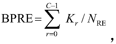
- ⁇ TF 0 or 10log 10 (2 BPRE -1) or a value determined according to MCS;
- C is the number of code blocks
- K r is the size of code block K
- N RE is the number of remaining REs in resource elements (RE) occupied by the PUSCH to remove demodulation reference signals (DMRS);
- ⁇ n is the power adjustment value
- the ⁇ delta and ⁇ delta_msg3 are configured through the same parameter or configured through different parameters, the ⁇ delta is the power offset value of the PUSCH relative to the pilot, and the ⁇ delta_msg3 is the Msg3 relative pilot in the four-step random access procedure. Frequency power offset value.
- the determination process of ⁇ n includes:
- ⁇ n is zero
- ⁇ n is the first PUSCH transmission from or to this PUSCH transmission time, determining a rise over the total power; MsgA comprising the pilot and PUSCH.
- ⁇ n is the determined total power increase value from the first PUSCH transmission to this or last PUSCH transmission, including:
- ⁇ n ⁇ P rampup_pusch ;
- P CMAX is the configured maximum transmission power or configured transmission power
- PO_PRE is the pilot receiving target power
- ⁇ delta is the configured power offset value
- u is the subcarrier spacing configuration parameter
- ⁇ is the configuration parameter
- PL is the path loss
- ⁇ TF 0 or 10log 10 (2 BPRE -1) or a value determined according to MCS;
- the C is the number of code blocks
- K r is the size of code block K
- N RE is the number of remaining REs of the resource unit RE occupied by the DMRS excluding the PUSCH;
- ⁇ P rampup_pusch_n (n-1) ⁇ s PUSCH ;
- s PUSCH is the configured PUSCH power adjustment step value, and the PUSCH power adjustment step value and the pilot power adjustment step value are independently configured the same or different values;
- n-1) is the PUSCH power adjustment The number of times, n is an integer greater than or equal to 1.
- obtaining the transmission power of the pilot according to the system information, and obtaining the transmission power of the PUSCH according to the transmission power of the pilot includes:
- the P CMAX is the configured maximum transmission power or the configured transmission power
- P PRE is the transmission power of the pilot
- ⁇ Delta is the configured power offset value
- u is the subcarrier spacing configuration parameter
- ⁇ TF 0 or 10log 10 (2 BPRE -1) or a value determined according to MCS;
- C is the number of code blocks
- K r is the size of code block K
- N RE is the number of remaining REs of the resource unit RE occupied by the PUSCH excluding the DMRS;
- ⁇ n is the power adjustment value
- the determination process of ⁇ n includes:
- MsgA is the first transmission in the random access procedure, or if at least one MsgA is successfully transmitted within a preset time period before this MsgA transmission, then ⁇ n is zero, or is the configured parameter ⁇ 0 , or , The same as the value of ⁇ n-1 in the last MsgA transmission;
- ⁇ n is the first PUSCH transmission from or to this PUSCH transmission time, determining a rise over the total power; MsgA comprising the pilot and PUSCH.
- ⁇ n is the determined total power increase value from the first PUSCH transmission to this or last PUSCH transmission, including:
- the P CMAX is the configured maximum transmission power or the configured transmission power
- P PRE is the transmission power of the pilot
- ⁇ Delta is the configured offset value
- u is the subcarrier spacing configuration parameter
- ⁇ TF 0 or 10log 10 (2 BPRE -1) or the value determined by MCS; wherein, the Where, C is the number of code blocks, K r is the size of code block K, and NRE is the number of remaining REs of the resource unit RE occupied by the PUSCH excluding the DMRS;
- ⁇ P rampup_pusch_n (n-1) ⁇ s ⁇ ;
- n-1 is the number of PUSCH power adjustments, and n is an integer greater than or equal to 1;
- s ⁇ is the difference between the PUSCH power adjustment step value and the pilot power adjustment step value, and the PUSCH power adjustment step value and the pilot power adjustment step value are respectively configured the same or different values.
- the embodiment of the present disclosure also provides a terminal, including:
- Transceiver used to receive system information
- a processor configured to obtain the transmission power of the physical uplink shared channel PUSCH in the random access procedure according to the system information
- the transceiver is further configured to transmit the PUSCH according to the transmission power of the PUSCH.
- the processor is specifically configured to: obtain the transmission power of the PUSCH according to at least one of the PUSCH bandwidth, the pilot reception target power, and the configured power offset value in the system information; or
- the system information obtains the transmission power of the pilot, and obtains the transmission power of the PUSCH according to the transmission power of the pilot.
- obtaining the transmission power of the PUSCH according to at least one of the PUSCH bandwidth, the pilot reception target power, and the configured power offset value in the system information includes:
- the P CMAX is the configured maximum transmission power or the configured transmission power
- PO_PRE is the pilot receiving target power
- ⁇ delta is the configured power offset value
- u is the subcarrier spacing configuration parameter
- ⁇ is the configuration parameter
- PL is the path loss
- ⁇ TF 0 or 10log 10 (2 BPRE -1) or a value determined according to MCS;
- C is the number of code blocks
- K r is the size of code block K
- N RE is the number of remaining REs of the resource unit RE occupied by the DMRS excluding the PUSCH;
- ⁇ n is the power adjustment value
- obtaining the transmission power of the pilot according to the system information, and obtaining the transmission power of the PUSCH according to the transmission power of the pilot includes:
- the P CMAX is the configured maximum transmission power or the configured transmission power
- P PRE is the transmission power of the pilot
- ⁇ Delta is the configured power offset value
- u is the subcarrier spacing configuration parameter
- ⁇ TF 0 or 10log 10 (2 BPRE -1) or a value determined according to MCS;
- C is the number of code blocks
- K r is the size of code block K
- N RE is the number of remaining REs of the resource unit RE occupied by the PUSCH excluding the DMRS;
- ⁇ n is the power adjustment value
- the embodiment of the present disclosure also provides a random access device, including:
- Transceiver module used to receive system information
- a processing module configured to obtain the transmission power of the physical uplink shared channel PUSCH in the random access procedure according to the system information
- the transceiver module is further configured to send the PUSCH according to the transmission power of the PUSCH.
- the processing module is specifically configured to: obtain the transmission power of the PUSCH according to at least one of the PUSCH bandwidth, the pilot received target power, and the configured power offset value in the system information; or
- the system information obtains the transmission power of the pilot, and obtains the transmission power of the PUSCH according to the transmission power of the pilot.
- obtaining the transmission power of the PUSCH according to at least one of the PUSCH bandwidth, the pilot reception target power, and the configured power offset value in the system information includes:
- the P CMAX is the configured maximum transmission power or the configured transmission power
- PO_PRE is the pilot receiving target power
- ⁇ delta is the configured power offset value
- u is the subcarrier spacing configuration parameter
- ⁇ is the configuration parameter
- PL is the path loss
- ⁇ TF 0 or 10log 10 (2 BPRE -1) or a value determined according to MCS;
- C is the number of code blocks
- K r is the size of code block K
- N RE is the number of remaining REs of the resource unit RE occupied by the DMRS excluding the PUSCH;
- ⁇ n is the power adjustment value
- obtaining the transmission power of the pilot according to the system information, and obtaining the transmission power of the PUSCH according to the transmission power of the pilot includes:
- the P CMAX is the configured maximum transmission power or the configured transmission power
- P PRE is the transmission power of the pilot
- ⁇ Delta is the configured power offset value
- u is the subcarrier spacing configuration parameter
- ⁇ TF 0 or 10log 10 (2 BPRE -1) or a value determined according to MCS;
- C is the number of code blocks
- K r is the size of code block K
- N RE is the number of remaining REs of the PUSCH excluding DMRS
- ⁇ n is the power adjustment value
- An embodiment of the present disclosure also provides a terminal, including a processor and a memory storing a computer program, and when the computer program is run by the processor, the method described above is executed.
- Embodiments of the present disclosure also provide a computer-readable storage medium, including instructions, which when run on a computer, cause the computer to execute the method described above.
- the transmission power of the physical uplink shared channel PUSCH in the random access procedure is obtained according to the system information; and the PUSCH is transmitted according to the transmission power of the PUSCH.
- the PUSCH power can be determined based on system information in an open-loop, which is suitable for the transmission of PUSCH in 2-step RACH MsgA. Power control can be performed on the transmission of PUSCH in MsgA, so as to better ensure the transmission performance of MsgA in the random access procedure.
- the flexibility of the system configuration can be guaranteed, and the configuration of the PUSCH power in the MsgA can be prevented from being restricted by the 4-step RACH process in the related technology.
- the value configured for 2-step RACH may be larger than the value configured for 2-step RACH, which ensures transmission reliability under open-loop power control.
- the PUSCH power adjustment step value and pilot power adjustment step value in this solution are independently configured, which ensures that the transmission power can be adjusted independently according to the PUSCH channel characteristics, which can avoid binding with the power adjustment of the pilot. Better improve the transmission performance of PUSCH, so as to better guarantee the transmission performance of MsgA in the random access process.
- the technical solution of obtaining the transmission power of the PUSCH according to the transmission power of the pilot in the present disclosure can avoid the repeated calculation of certain parameters when calculating the PUSCH power, and relatively reduce the calculation complexity.
- Figure 1 is a schematic diagram of a four-step random access process
- Figure 2 is a schematic diagram of a two-step random access process
- FIG. 3 is a schematic flowchart of the random access method of the present disclosure
- Figure 4 is a schematic diagram of the terminal architecture of the present disclosure.
- an embodiment of the present disclosure provides a random access method applied to a terminal, including:
- Step 31 Obtain the transmission power of the physical uplink shared channel PUSCH in the random access procedure according to the system information, the system information is received before the random access procedure is performed;
- Step 32 Send the PUSCH according to the transmission power of the PUSCH.
- the transmission power of the physical uplink shared channel PUSCH in the random access procedure is obtained according to the system information; and the PUSCH is transmitted according to the transmission power of the PUSCH.
- the PUSCH power can be determined based on system information in an open-loop, which is suitable for the transmission of PUSCH in 2-step RACH MsgA. Power control can be performed on the transmission of PUSCH in MsgA, so as to better ensure the transmission performance of MsgA in the random access procedure.
- step 31 may specifically include:
- Step 311 Obtain the transmission power of the PUSCH according to at least one of the PUSCH bandwidth, the pilot reception target power, and the configured power offset value in the system information; or
- Step 312 Obtain the transmission power of the pilot according to the system information, and obtain the transmission power of the PUSCH according to the transmission power of the pilot.
- the system information indicates the pilot reception target power
- the pilot transmission power may be the same as the pilot reception target power, or the pilot transmission power may be calculated through a preset algorithm based on the pilot reception target power.
- step 311 may specifically include:
- the P CMAX is the configured maximum transmission power or the configured transmission power
- PO_PRE is the pilot receiving target power
- ⁇ delta is the configured power offset value
- u is the subcarrier spacing configuration parameter
- Is PUSCH bandwidth expressed by the number of RBs (resource blocks)
- ⁇ is the configuration parameter
- PL is the path loss
- ⁇ TF 0 or 10log 10 (2 BPRE -1) or a value determined according to MCS;
- C is the number of code blocks
- K r is the size of code block K
- N RE is the number of remaining REs (resource units) occupied by the PUSCH excluding the DMRS;
- ⁇ n is the power adjustment value
- RB is defined as 12 consecutive subcarriers in the frequency domain; RE is defined as one subcarrier on one symbol.
- the ⁇ delta and ⁇ delta_msg3 are configured through the same parameter or configured through different parameters, the ⁇ delta is the power offset value of the PUSCH relative to the pilot, and the ⁇ delta_msg3 is the Msg3 relative pilot in the four-step random access procedure. Frequency power offset value.
- ⁇ n when determining ⁇ n , it may specifically include:
- ⁇ n is the first PUSCH transmission from or to this PUSCH transmission time, determining a rise over the total power; MsgA comprising the pilot and PUSCH.
- ⁇ n is the determined total power increase value from the first PUSCH transmission to this or last PUSCH transmission, including:
- ⁇ n ⁇ P rampup_pusch ;
- P CMAX is the configured maximum transmission power or configured transmission power
- PO_PRE is the pilot receiving target power
- ⁇ delta is the configured power offset value
- u is the subcarrier spacing configuration parameter
- ⁇ is the configuration parameter
- PL is the path loss
- ⁇ TF 0 or 10log 10 (2 BPRE -1) or a value determined according to MCS;
- the C is the number of code blocks
- K r is the size of code block K
- N RE is the number of remaining REs from the PUSCH excluding DMRS
- ⁇ P rampup_pusch_n (n-1) ⁇ s PUSCH ;
- s PUSCH is the configured PUSCH power adjustment step value, and the PUSCH power adjustment step value and the pilot power adjustment step value are independently configured the same or different values;
- n-1) is the PUSCH power adjustment The number of times, n is an integer greater than or equal to 1.
- step 312 may specifically include:
- the P CMAX is the configured maximum transmission power or the configured transmission power
- P PRE is the transmission power of the pilot
- ⁇ Delta is the configured power offset value
- u is the subcarrier spacing configuration parameter
- ⁇ TF 0 or 10log 10 (2 BPRE -1) or a value determined according to MCS;
- C is the number of code blocks
- K r is the size of code block K
- N RE is the number of remaining REs of the PUSCH excluding DMRS
- ⁇ n is the power adjustment value
- the determination process of ⁇ n includes:
- MsgA is the first transmission in the random access procedure, or if at least one MsgA is successfully transmitted within a preset time period before this MsgA transmission, then ⁇ n is zero, or is the configured parameter ⁇ 0 , or , Which is the same as the value of ⁇ n-1 in the last MsgA transmission;
- ⁇ n is the first PUSCH transmission from or to this PUSCH transmission time, determining a rise over the total power; MsgA comprising the pilot and PUSCH.
- ⁇ n is the determined total power increase value from the first PUSCH transmission to this or last PUSCH transmission, including:
- the P CMAX is the configured maximum transmission power or the configured transmission power
- P PRE is the transmission power of the pilot
- ⁇ Delta is the configured power offset value
- u is the subcarrier spacing configuration parameter
- Is the bandwidth of PUSCH, expressed by the number of RBs
- ⁇ TF 0 or 10log 10 (2 BPRE -1) or a value determined by MCS; wherein, the Wherein, C is the number of code blocks, K r is the size of code block K, and N RE is the number of remaining REs of the PUSCH excluding DMRS;
- ⁇ P rampup_pusch_n (n-1) ⁇ s ⁇ ;
- n-1 is the number of PUSCH power adjustments, and n is an integer greater than or equal to 1;
- s ⁇ is the difference between the PUSCH power adjustment step value and the pilot power adjustment step value, and the PUSCH power adjustment step value and the pilot power adjustment step value are respectively configured the same or different values.
- step 32 when sending the PUSCH, it may further include: sending a pilot in the random access procedure; the transmission power of the pilot is determined according to system information, and the pilot The transmission power of the pilot frequency may be the same as the pilot reception target power indicated in the system information, or the pilot transmission power may be calculated through a preset algorithm according to the pilot reception target power.
- the random access method may further include: receiving a random access response message (ie, MsgB) sent by the network device.
- MsgB random access response message
- the transmission power of the physical uplink shared channel PUSCH in the random access procedure is obtained by using system information; and the PUSCH is transmitted according to the transmission power of the PUSCH.
- This is an open-loop power control method that can be used to determine the transmission power of PUSCH in MsgA.
- different power adjustment step values can be configured for the pilot and PUSCH, no closed-loop indication on the base station side is required, and the power of the PUSCH can be determined in an open loop, which is suitable for the PUSCH in 2-step RACH MsgA. transmission.
- the ⁇ delta is the power offset value of the PUSCH relative to the pilot, which can be independently configured with ⁇ delta_msg3 , which ensures the flexibility of system configuration and avoids that the configuration of the PUSCH power in the MsgA is bound to ⁇ delta_msg3 .
- the value of ⁇ delta configuration can be larger than ⁇ delta_msg3 , which ensures the transmission reliability under open loop power control.
- the PUSCH power adjustment step value and pilot power adjustment step value in the solution are independently configured, which ensures that the transmission power can be adjusted independently according to the PUSCH channel characteristics, which can avoid binding with the power adjustment of the pilot, and can be more Improve the transmission performance of PUSCH, so as to better guarantee the transmission performance of MsgA in the random access process.
- the above-mentioned solution of the present disclosure obtains the transmission power of the PUSCH according to the transmission power of the pilot.
- the advantage of this method is that the pilot power value is calculated first, and then the PUSCH power value is obtained based on the pilot power value. Specifically, the power value of the pilot is obtained according to the system information. Therefore, the method avoids the repeated calculation of certain parameters when calculating the PUSCH power, and relatively reduces the calculation complexity.
- an embodiment of the present disclosure further provides a terminal 40, including:
- the transceiver 41 is used to receive system information
- the processor 42 is configured to obtain the transmission power of the physical uplink shared channel PUSCH in the random access procedure according to the system information;
- the transceiver 41 is also configured to transmit the PUSCH according to the transmission power of the PUSCH.
- the processor 42 is specifically configured to: obtain the transmission power of the PUSCH according to at least one of the PUSCH bandwidth, the pilot received target power, and the configured power offset value in the system information; or, according to The system information obtains the transmission power of the pilot, and obtains the transmission power of the PUSCH according to the transmission power of the pilot.
- obtaining the transmission power of the PUSCH according to at least one of the PUSCH bandwidth, the pilot reception target power, and the configured power offset value in the system information includes:
- the P CMAX is the configured maximum transmission power or the configured transmission power
- PO_PRE is the pilot receiving target power
- ⁇ delta is the configured power offset value
- u is the subcarrier spacing configuration parameter
- ⁇ is the configuration parameter
- PL is the path loss
- ⁇ TF 0 or 10log 10 (2 BPRE -1) or a value determined according to MCS;
- C is the number of code blocks
- K r is the size of code block K
- N RE is the number of remaining REs (resource units) occupied by the PUSCH excluding the DMRS;
- ⁇ n is the power adjustment value
- the ⁇ delta and ⁇ delta_msg3 are configured through the same parameter or configured through different parameters, the ⁇ delta is the power offset value of the PUSCH relative to the pilot, and the ⁇ delta_msg3 is the Msg3 relative pilot in the four-step random access procedure. Frequency power offset value.
- the determination process of ⁇ n includes:
- the random access procedure is a random access request message MsgA first transmission or a preset period of time before transmitting the at least one MsgA MsgA successfully transmitted, ⁇ n is zero;
- ⁇ n is the first PUSCH transmission from or to this PUSCH transmission time, determining a rise over the total power; MsgA comprising the pilot and PUSCH.
- ⁇ n is the determined total power increase value from the first PUSCH transmission to this or last PUSCH transmission, including:
- ⁇ n ⁇ P rampup_pusch ;
- P CMAX is the configured maximum transmission power or configured transmission power
- PO_PRE is the pilot receiving target power
- ⁇ delta is the configured power offset value
- u is the subcarrier spacing configuration parameter
- ⁇ is the configuration parameter
- PL is the path loss
- ⁇ TF 0 or 10log 10 (2 BPRE -1) or a value determined according to MCS;
- the C is the number of code blocks
- K r is the size of code block K
- N RE is the number of remaining REs from the PUSCH excluding DMRS
- ⁇ P rampup_pusch_n (n-1) ⁇ s PUSCH ;
- s PUSCH is the configured PUSCH power adjustment step value, and the PUSCH power adjustment step value and the pilot power adjustment step value are independently configured the same or different values;
- n-1) is the PUSCH power adjustment The number of times, n is an integer greater than or equal to 1.
- obtaining the transmission power of the pilot according to the system information and obtaining the transmission power of the PUSCH according to the transmission power of the pilot includes:
- the P CMAX is the configured maximum transmission power or the configured transmission power
- P PRE is the transmission power of the pilot
- ⁇ Delta is the configured power offset value
- u is the subcarrier spacing configuration parameter
- ⁇ TF 0 or 10log 10 (2 BPRE -1) or a value determined according to MCS;
- C is the number of code blocks
- K r is the size of code block K
- N RE is the number of remaining REs of the PUSCH excluding DMRS
- ⁇ n is the power adjustment value
- the determination process of ⁇ n includes:
- MsgA is the first transmission in the random access procedure, or if at least one MsgA is successfully transmitted within a preset time period before this MsgA transmission, then ⁇ n is zero, or is the configured parameter ⁇ 0 , or , The same as the value of ⁇ n-1 in the last MsgA transmission;
- ⁇ n is the first PUSCH transmission from or to this PUSCH transmission time, determining a rise over the total power; MsgA comprising the pilot and PUSCH.
- ⁇ n is the determined total power increase value from the first PUSCH transmission to this or last PUSCH transmission, including:
- the P CMAX is the configured maximum transmission power or the configured transmission power
- P PRE is the transmission power of the pilot
- ⁇ Delta is the configured power offset value
- u is the subcarrier spacing configuration parameter
- Is the bandwidth of PUSCH, expressed by the number of RBs
- ⁇ TF 0 or 10log 10 (2 BPRE -1) or a value determined by MCS; wherein, the Wherein, C is the number of code blocks, K r is the size of code block K, and NRE is the number of remaining REs of the PUSCH excluding DMRS;
- ⁇ P rampup_pusch_n (n-1) ⁇ s ⁇ ;
- n-1 is the number of PUSCH power adjustments, and n is an integer greater than or equal to 1;
- s ⁇ is the difference between the PUSCH power adjustment step value and the pilot power adjustment step value, and the PUSCH power adjustment step value and the pilot power adjustment step value are respectively configured the same or different values.
- the transceiver is further configured to: send the pilot in the random access procedure; and receive the random access response message in the random access procedure sent by the network device.
- the terminal 40 may further include: a memory 43, the transceiver 41 and the processor 42, and the transceiver 41 and the memory 43 can all be connected through a bus interface.
- the function of the transceiver 41 can be implemented by the processor 42 to process
- the function of the transmitter 42 can also be implemented by the transceiver 41.
- the embodiment of the present disclosure also provides a random access device, including:
- Transceiver module used to receive system information
- a processing module configured to obtain the transmission power of the physical uplink shared channel PUSCH in the random access procedure according to the system information
- the transceiver module is further configured to send the PUSCH according to the transmission power of the PUSCH.
- the processing module is specifically configured to: obtain the transmission power of the PUSCH according to at least one of the PUSCH bandwidth, the pilot received target power, and the configured power offset value in the system information; or
- the system information obtains the transmission power of the pilot, and obtains the transmission power of the PUSCH according to the transmission power of the pilot.
- obtaining the transmission power of the PUSCH according to at least one of the PUSCH bandwidth, the pilot reception target power, and the configured power offset value in the system information includes:
- the P CMAX is the configured maximum transmission power or the configured transmission power
- PO_PRE is the pilot receiving target power
- ⁇ delta is the configured power offset value
- u is the subcarrier spacing configuration parameter
- ⁇ is the configuration parameter
- PL is the path loss
- ⁇ TF 0 or 10log 10 (2 BPRE -1) or a value determined according to MCS;
- C is the number of code blocks
- K r is the size of code block K
- N RE is the number of remaining REs of the resource unit RE occupied by the DMRS excluding the PUSCH;
- ⁇ n is the power adjustment value
- obtaining the transmission power of the pilot according to the system information, and obtaining the transmission power of the PUSCH according to the transmission power of the pilot includes:
- the P CMAX is the configured maximum transmission power or the configured transmission power
- P PRE is the transmission power of the pilot
- ⁇ Delta is the configured power offset value
- u is the subcarrier spacing configuration parameter
- ⁇ TF 0 or 10log 10 (2 BPRE -1) or a value determined according to MCS;
- C is the number of code blocks
- K r is the size of code block K
- N RE is the number of remaining REs of the PUSCH excluding DMRS
- ⁇ n is the power adjustment value
- the device is a device corresponding to the above-mentioned terminal method, and all the implementation manners in the above-mentioned method embodiment are applicable to the embodiment of the terminal, and the same technical effect can be achieved.
- the embodiment of the present disclosure also provides a terminal, including: a processor, a memory storing a computer program, and when the computer program is run by the processor, all implementations in the above method embodiment of the terminal side method shown in FIG. 2 are executed
- a terminal including: a processor, a memory storing a computer program, and when the computer program is run by the processor, all implementations in the above method embodiment of the terminal side method shown in FIG. 2 are executed
- the methods are all applicable to this embodiment, and the same technical effect can be achieved.
- Embodiments of the present disclosure also provide a computer-readable storage medium, including instructions, which when run on a computer, cause the computer to execute the method described above. All the implementation manners in the foregoing method embodiment are applicable to this embodiment, and the same technical effect can also be achieved.
- the above-mentioned solution of the present disclosure obtains the transmission power of the physical uplink shared channel PUSCH in the random access process according to the system information, the system information is received before the random access process;
- the PUSCH does not require a closed loop indication on the base station side, can determine the power of the PUSCH in an open loop, and is suitable for PUSCH transmission in 2-step RACH MsgA.
- the ⁇ delta is the power offset value of the PUSCH relative to the pilot, which can be independently configured with ⁇ delta_msg3 , which ensures the flexibility of system configuration and avoids that the configuration of the PUSCH power in the MsgA is bound to ⁇ delta_msg3 .
- the value of ⁇ delta configuration can be larger than ⁇ delta_msg3 , which ensures the transmission reliability under open loop power control.
- the PUSCH power adjustment step value and pilot power adjustment step value in the solution are independently configured, which ensures that the transmission power can be adjusted independently according to the PUSCH channel characteristics, which can avoid binding with the power adjustment of the pilot, and can be more Improve the transmission performance of PUSCH, so as to better guarantee the transmission performance of MsgA in the random access process.
- the above-mentioned solution of the present disclosure obtains the transmission power of the PUSCH according to the transmission power of the pilot.
- the advantage of this method is that the pilot power value is calculated first, and then the PUSCH power value is obtained based on the pilot power value. Specifically, the power value of the pilot is obtained according to the system information. Therefore, the method avoids the repeated calculation of certain parameters when calculating the PUSCH power, and relatively reduces the calculation complexity.
- the disclosed device and method may be implemented in other ways.
- the device embodiments described above are only illustrative.
- the division of the units is only a logical function division, and there may be other divisions in actual implementation, for example, multiple units or components can be combined or It can be integrated into another system, or some features can be ignored or not implemented.
- the displayed or discussed mutual coupling or direct coupling or communication connection may be indirect coupling or communication connection through some interfaces, devices or units, and may be in electrical, mechanical or other forms.
- the units described as separate components may or may not be physically separated, and the components displayed as units may or may not be physical units, that is, they may be located in one place, or they may be distributed on multiple network units. Some or all of the units may be selected according to actual needs to achieve the objectives of the solutions of the embodiments.
- the functional units in the various embodiments of the present disclosure may be integrated into one processing unit, or each unit may exist alone physically, or two or more units may be integrated into one unit.
- the function is implemented in the form of a software functional unit and sold or used as an independent product, it can be stored in a computer readable storage medium.
- the technical solution of the present disclosure essentially or the part that contributes to the related technology or the part of the technical solution can be embodied in the form of a software product.
- the computer software product is stored in a storage medium, including several
- the instructions are used to make a computer device (which may be a personal computer, a server, or a network device, etc.) execute all or part of the steps of the methods described in the various embodiments of the present disclosure.
- the aforementioned storage media include: U disk, mobile hard disk, ROM, RAM, magnetic disk or optical disk and other media that can store program codes.
- the program can be stored in a computer readable storage medium. When executed, it may include the processes of the above-mentioned method embodiments.
- the storage medium may be a magnetic disk, an optical disk, a read-only memory (Read-Only Memory, ROM), or a random access memory (Random Access Memory, RAM), etc.
- modules, units, and sub-units can be implemented in one or more Application Specific Integrated Circuits (ASIC), Digital Signal Processor (DSP), Digital Signal Processing Device (DSP Device, DSPD) ), Programmable Logic Device (PLD), Field-Programmable Gate Array (FPGA), general-purpose processors, controllers, microcontrollers, microprocessors, used to implement Described functions in other electronic units or combinations thereof.
- ASIC Application Specific Integrated Circuits
- DSP Digital Signal Processor
- DSP Device Digital Signal Processing Device
- DSPD Digital Signal Processing Device
- PLD Programmable Logic Device
- FPGA Field-Programmable Gate Array
- the technology described in the embodiments of the present disclosure can be implemented by modules (for example, procedures, functions, etc.) that perform the functions described in the embodiments of the present disclosure.
- the software codes can be stored in the memory and executed by the processor.
- the memory can be implemented in the processor or external to the processor.
- each component or each step can be decomposed and/or recombined.
- decomposition and/or recombination should be regarded as equivalent solutions of the present disclosure.
- the steps of performing the above series of processing can naturally be performed in a time sequence in the order of description, but do not necessarily need to be performed in a time sequence, and some steps can be performed in parallel or independently of each other.
- the purpose of the present disclosure can also be realized by running a program or a group of programs on any computing device.
- the computing device may be a well-known general-purpose device. Therefore, the purpose of the present disclosure can also be achieved only by providing a program product containing program code for implementing the method or device. That is, such a program product also constitutes the present disclosure, and a storage medium storing such a program product also constitutes the present disclosure.
- the storage medium may be any well-known storage medium or any storage medium developed in the future. It should also be pointed out that, in the device and method of the present disclosure, obviously, each component or each step can be decomposed and/or recombined.
Landscapes
- Engineering & Computer Science (AREA)
- Computer Networks & Wireless Communication (AREA)
- Signal Processing (AREA)
- Mobile Radio Communication Systems (AREA)
Abstract
本公开的实施例提供一种随机接入方法及终端,所述方法包括:根据系统信息,获得随机接入流程中物理上行共享信道PUSCH的传输功率;根据所述PUSCH的传输功率,发送所述PUSCH。
Description
相关申请的交叉引用
本申请主张在2019年4月25日在中国提交的中国专利申请号No.201910340585.4的优先权,其全部内容通过引用包含于此。
本公开涉及通信技术领域,特别是指一种随机接入方法及终端。
相关技术中,如图1所示,终端发起基于竞争的随机接入(Contention-based Random Access,CBRA)的4-step随机接入信道(Random Access Channel,RACH)流程大致如下:
1)终端在物理随机接入信道(Physical Random Access Channel,PRACH)的资源上发送包含Preamble(前导序列、前导码或者导频)的上行信号,称为Msg1;
2)终端接收基站侧发送的随机接入响应(Random Access Response,RAR),称为Msg2;
3)终端在RAR指示的上行时频资源上发送上行数据,称为Msg3;
4)终端接收基站侧发送的下行数据,该下行数据包含竞争解决相关信息,称为Msg4。
为了降低随机接入时延,如图2所示,随机接入流程可以为2-step RACH,即将原4-step RACH中的Msg1和Msg3集中在一步发送,称为MsgA;Msg2和Msg4则进一步合并为MsgB,具体消息内容可能会有变化。
原4-step RACH流程,终端在发送Msg3时,需要进行闭环功率控制,以提升Msg3传输的可靠性。其方法是Msg2(RAR)中包括媒体访问控制-控制单元(Medium Access Control-Control Element,MAC-CE)信息指示,MAC-CE中的上行调度(Uplink grant,UL-grant)域共占用27比特,见表1。
表1

其中TPC command占用的3个比特用于调整Msg3的发送功率。具体的TPC command与功率偏移值的对应,见表2。
表2
| TPC Command | Value(in dB) |
| 0 | -6 |
| 1 | -4 |
| 2 | -2 |
| 3 | 0 |
| 4 | 2 |
| 5 | 4 |
| 6 | 6 |
| 7 | 8 |
在2-step RACH流程中,终端在第一步MsgA中就将发送PUSCH,因此,不能采用相关技术中的闭环功率控制方法。
发明内容
本公开提供了一种随机接入方法及终端,从而更好的保证两步随机接入流程中MsgA的传输性能。
为解决上述技术问题,本公开的实施例提供如下方案:
一种两步随机接入方法,应用于终端,所述方法包括:
根据系统信息,获得随机接入流程中物理上行共享信道(Physical Uplink Shared Channel,PUSCH)的传输功率;
根据所述PUSCH的传输功率,发送所述PUSCH。
其中,根据系统信息,获得随机接入流程中物理上行共享信道PUSCH的传输功率,包括:
根据所述系统信息中的PUSCH带宽、导频接收目标功率以及配置的功率偏移值中的至少一项,获得所述PUSCH的传输功率;或者,
根据所述系统信息获取导频的传输功率,根据所述导频传输功率,获得所述PUSCH的传输功率。
其中,根据所述系统信息中的PUSCH带宽、导频接收目标功率以及配置的功率偏移值中的至少一项,获得所述PUSCH的传输功率,包括:
通过公式
 获得所述PUSCH的传输功率;
其中,所述P
CMAX为配置的最大传输功率或配置的传输功率;
P
O_PRE为导频接收目标功率;
Δ
delta为配置的功率偏移值;
u为子载波间隔配置参数;

α为配置参数;
PL为路径损耗;
Δ
TF=0或者10log
10(2
BPRE-1)或者根据MCS确定的值;
其中,所述

C为码块个数,K
r为码块K的尺寸,N
RE为所述PUSCH去除解调参考信号(Demodulation Reference Signal,DMRS)所占资源单元(resource element,RE)的剩余RE个数;
Δ
n为功率调整值。
其中,所述Δ
delta与Δ
delta_msg3通过相同参数配置的或通过不同参数配置,所述Δ
delta为PUSCH相对导频的功率偏移值,所述Δ
delta_msg3为四步随机接入流程中Msg3相对导频的功率偏移值。
其中,所述Δ
n的确定过程,包括:
如果所述随机接入流程中MsgA为第一次传输,或者,此次MsgA发送以前一预设时间段内的至少一次MsgA成功发送,则Δ
n为零;
或者,Δ
n为从第一次PUSCH传输到本次或上一次PUSCH传输,确定的总功率上升值;所述MsgA包括导频和PUSCH。
其中,Δ
n为从第一次PUSCH传输到本次或上一次PUSCH传输,确定的总功率上升值,包括:
Δ
n=ΔP
rampup_pusch;
ΔP
rampup_pusch通过公式:ΔP
rampup_pusch={max{0,P
CMAX-P},ΔP
rampup_pusch_n}确定;
其中,P
CMAX为配置的最大传输功率或配置的传输功率;

P
O_PRE为导频接收目标功率;
Δ
delta为配置的功率偏移值;
u为子载波间隔配置参数;

α为配置参数;
PL为路径损耗;
Δ
TF=0或者10log
10(2
BPRE-1)或者根据MCS确定的值;
其中,所述
 C为码块个数,K
r为码块K的尺寸,N
RE为所述PUSCH去除DMRS所占资源单元RE的剩余RE个数;
C为码块个数,K
r为码块K的尺寸,N
RE为所述PUSCH去除DMRS所占资源单元RE的剩余RE个数;
ΔP
rampup_pusch_n可以通过公式:ΔP
rampup_pusch_n=(n-1)×s
PUSCH确定;
其中,s
PUSCH为配置的PUSCH功率调整步进值,所述PUSCH功率调整步进值与导频功率调整步进值是独立配置的相同的或不同的值;(n-1)为PUSCH功率调整的次数,n为大于或等于1的整数。
其中,根据所述系统信息获取导频的传输功率,根据所述导频的传输功率,获得所述PUSCH的传输功率,包括:
通过
 获得所述PUSCH的传输功率;
其中,所述P
CMAX为配置的最大传输功率或配置的传输功率
P
PRE为导频的传输功率;
Δ
Delta为配置的功率偏移值;
u为子载波间隔配置参数;

Δ
TF=0或者10log
10(2
BPRE-1)或者根据MCS确定的值;
所述
 其中,C为码块个数,K
r为码块K的尺寸,N
RE为所述PUSCH去除DMRS所占资源单元RE的剩余RE个数;
其中,C为码块个数,K
r为码块K的尺寸,N
RE为所述PUSCH去除DMRS所占资源单元RE的剩余RE个数;
Δ
n为功率调整值。
其中,Δ
n的确定过程,包括:
如果所述随机接入流程中MsgA为第一次传输,或者此次MsgA发送以前一预设时间段内的至少一次MsgA成功发送,则Δ
n为零,或者,为配置的参数Δ
0,或者,与上一次MsgA传输中的Δ
n-1值相同;
或者,Δ
n为从第一次PUSCH传输到本次或上一次PUSCH传输,确定的总功率上升值;所述MsgA包括导频和PUSCH。
其中,Δ
n为从第一次PUSCH传输到本次或上一次PUSCH传输,确定的总功率上升值,包括:
Δ
n=ΔP
rampup_pusch,
ΔP
rampup_pusch通过公式:ΔP
rampup_pusch={max{0,P
CMAX-P},ΔP
rampup_pusch_n}确定;
其中,所述P
CMAX为配置的最大传输功率或配置的传输功率;


Δ
TF=0或者10log
10(2
BPRE-1)或者MCS确定的值;其中,所述
 其中,C为码块个数,K
r为码块K的尺寸,NRE为所述PUSCH去除DMRS所占资源单元RE的剩余RE个数;
其中,C为码块个数,K
r为码块K的尺寸,NRE为所述PUSCH去除DMRS所占资源单元RE的剩余RE个数;
ΔP
rampup_pusch_n可以通过公式:ΔP
rampup_pusch_n=(n-1)×s
Δ确定;
其中,n-1为PUSCH功率调整的次数,n为大于或等于1的整数;
s
Δ为PUSCH功率调整步进值和导频功率调整步进值的差值,PUSCH功率调整步进值和导频功率调整步进值是分别配置的相同或者不同的值。
本公开的实施例还提供一种终端,包括:
收发机,用于接收系统信息;
处理器,用于根据所述系统信息,获得随机接入流程中物理上行共享信道PUSCH的传输功率;
所述收发机还用于根据所述PUSCH的传输功率,发送所述PUSCH。
其中,所述处理器具体用于:根据所述系统信息中的PUSCH带宽、导频接收目标功率以及配置的功率偏移值中的至少一项,获得所述PUSCH的传输功率;或者,根据所述系统信息获取导频的传输功率,根据所述导频的传输功率,获得所述PUSCH的传输功率。
其中,根据所述系统信息中的PUSCH带宽、导频接收目标功率以及配置的功率偏移值中的至少一项,获得所述PUSCH的传输功率,包括:
通过公式
 获得所述PUSCH的传输功率;
其中,所述P
CMAX为配置的最大传输功率或配置的传输功率;
P
O_PRE为导频接收目标功率;
Δ
delta为配置的功率偏移值;
u为子载波间隔配置参数;

α为配置参数;
PL为路径损耗;
Δ
TF=0或者10log
10(2
BPRE-1)或者根据MCS确定的值;
其中,所述

C为码块个数,K
r为码块K的尺寸,N
RE为所述PUSCH去除DMRS所占资源单元RE的剩余RE个数;
Δ
n为功率调整值。
其中,根据所述系统信息获取导频的传输功率,根据所述导频的传输功率,获得所述PUSCH的传输功率,包括:
通过公式:
 获得所述PUSCH的传输功率;
其中,所述P
CMAX为配置的最大传输功率或配置的传输功率;
P
PRE为导频的传输功率;
Δ
Delta为配置的功率偏移值;
u为子载波间隔配置参数;

Δ
TF=0或者10log
10(2
BPRE-1)或者根据MCS确定的值;
所述
 其中,C为码块个数,K
r为码块K的尺寸,N
RE为所述PUSCH去除DMRS所占资源单元RE的剩余RE个数;
其中,C为码块个数,K
r为码块K的尺寸,N
RE为所述PUSCH去除DMRS所占资源单元RE的剩余RE个数;
Δ
n为功率调整值。
本公开的实施例还提供一种随机接入装置,包括:
收发模块,用于接收系统信息;
处理模块,用于根据所述系统信息,获得随机接入流程中物理上行共享信道PUSCH的传输功率;
所述收发模块还用于根据所述PUSCH的传输功率,发送所述PUSCH。
其中,所述处理模块具体用于:根据所述系统信息中的PUSCH带宽、导频接收目标功率以及配置的功率偏移值中的至少一项,获得所述PUSCH的传输功率;或者,根据所述系统信息获取导频的传输功率,根据所述导频的传输功率,获得所述PUSCH的传输功率。
其中,根据所述系统信息中的PUSCH带宽、导频接收目标功率以及配置的功率偏移值中的至少一项,获得所述PUSCH的传输功率,包括:
通过公式
 获得所述PUSCH的传输功率;
其中,所述P
CMAX为配置的最大传输功率或配置的传输功率;
P
O_PRE为导频接收目标功率;
Δ
delta为配置的功率偏移值;
u为子载波间隔配置参数;

α为配置参数;
PL为路径损耗;
Δ
TF=0或者10log
10(2
BPRE-1)或者根据MCS确定的值;
其中,所述

C为码块个数,K
r为码块K的尺寸,N
RE为所述PUSCH去除DMRS所占资源单元RE的剩余RE个数;
Δ
n为功率调整值。
其中,根据所述系统信息获取导频的传输功率,根据所述导频的传输功率,获得所述PUSCH的传输功率,包括:
通过公式:
 获得所述PUSCH的传输功率;
其中,所述P
CMAX为配置的最大传输功率或配置的传输功率;
P
PRE为导频的传输功率;
Δ
Delta为配置的功率偏移值;
u为子载波间隔配置参数;

Δ
TF=0或者10log
10(2
BPRE-1)或者根据MCS确定的值;
所述
 其中,C为码块个数,K
r为码块K的尺寸,N
RE为所述PUSCH去除DMRS所占RE的剩余RE个数;
其中,C为码块个数,K
r为码块K的尺寸,N
RE为所述PUSCH去除DMRS所占RE的剩余RE个数;
Δ
n为功率调整值。
本公开的实施例还提供一种终端,包括:处理器、存储有计算机程序的存储器,所述计算机程序被处理器运行时,执行如上所述的方法。
本公开的实施例还提供一种计算机可读存储介质,包括指令,当所述指令在计算机运行时,使得计算机执行如上所述的方法。
本公开的上述方案至少包括以下有益效果:
本公开的上述方案,通过根据系统信息,获得随机接入流程中物理上行共享信道PUSCH的传输功率;根据所述PUSCH的传输功率,发送所述PUSCH。这样不需要基站侧的闭环指示,可以开环的基于系统信息确定PUSCH的功率,适用于2-step RACH MsgA中PUSCH的传输。可以对MsgA中PUSCH的传输进行功率控制,从而更好的保证随机接入流程中MsgA的传输性能。
通过针对2-step RACH独立配置PUSCH相对导频的功率偏移值,可以保证系统配置的灵活性,避免MsgA中PUSCH的功率的配置被相关技术中的4-step RACH流程限制。例如,考虑到开环功率的特性,针对2-step RACH配置的值可以相对针对2-step RACH配置的值更大一些,这样保证了开环功率控制下的传输可靠性。
此外,本方案中的PUSCH功率调整步进值和导频功率调整步进值是独立配置的,这样保证可以根据PUSCH信道特性独立的调整发送功率,可以避免和导频的功率调整绑定,可以更好的提升PUSCH的传输性能,从而更好的保证随机接入流程中MsgA的传输性能。
另一方面,本公开的中根据导频的传输功率获得PUSCH的传输功率的技术方案,可以避免了计算PUSCH功率时某些参数的重复计算,相对降低了计算复杂度。
图1为四步随机接入流程的示意图;
图2为两步随机接入流程的示意图;
图3为本公开的随机接入方法的流程示意图;
图4为本公开的终端架构示意图。
下面将参照附图更详细地描述本公开的示例性实施例。虽然附图中显示了本公开的示例性实施例,然而应当理解,可以以各种形式实现本公开而不 应被这里阐述的实施例所限制。相反,提供这些实施例是为了能够更透彻地理解本公开,并且能够将本公开的范围完整的传达给本领域的技术人员。
如图3所示,本公开的实施例提供一种随机接入方法,应用于终端,包括:
步骤31,根据系统信息,获得随机接入流程中物理上行共享信道PUSCH的传输功率,所述系统信息是在进行随机接入流程前接收到的;
步骤32,根据所述PUSCH的传输功率,发送所述PUSCH。
本公开的上述方案,通过根据系统信息,获得随机接入流程中物理上行共享信道PUSCH的传输功率;根据所述PUSCH的传输功率,发送所述PUSCH。这样不需要基站侧的闭环指示,可以开环的基于系统信息确定PUSCH的功率,适用于2-step RACH MsgA中PUSCH的传输。可以对MsgA中PUSCH的传输进行功率控制,从而更好的保证随机接入流程中MsgA的传输性能。
本公开的一具体实施例中,上述步骤31具体可以包括:
步骤311,根据所述系统信息中的PUSCH带宽、导频接收目标功率以及配置的功率偏移值中的至少一项,获得所述PUSCH的传输功率;或者
步骤312,根据所述系统信息获取导频的传输功率,根据所述导频的传输功率,获得所述PUSCH的传输功率。这里,系统信息中指示导频接收目标功率,而导频的传输功率可以与导频接收目标功率相同,或者导频的传输功率可以根据导频接收目标功率通过预设算法运算得到。
其中,步骤311具体可以包括:
通过公式
 获得所述PUSCH的传输功率;
其中,所述P
CMAX为配置的最大传输功率或配置的传输功率;
P
O_PRE为导频接收目标功率;
Δ
delta为配置的功率偏移值;
u为子载波间隔配置参数;

α为配置参数;
PL为路径损耗;
Δ
TF=0或者10log
10(2
BPRE-1)或者根据MCS确定的值;
其中,所述

C为码块个数,K
r为码块K的尺寸,N
RE为所述PUSCH去除DMRS所占RE(资源单元)的剩余RE个数;
Δ
n为功率调整值。
这里,RB定义为频域的12个连续的子载波;RE定义为一个符号上的一个子载波。
其中,所述Δ
delta与Δ
delta_msg3通过相同参数配置的或通过不同参数配置,所述Δ
delta为PUSCH相对导频的功率偏移值,所述Δ
delta_msg3为四步随机接入流程中Msg3相对导频的功率偏移值。
其中,确定Δ
n时,具体可以包括:
1)如果所述随机接入流程中MsgA为第一次传输,或者,此次MsgA发送以前一预设时间段内的至少一次MsgA成功发送,则Δ
n为零;
或者,Δ
n为从第一次PUSCH传输到本次或上一次PUSCH传输,确定的总功率上升值;所述MsgA包括导频和PUSCH。
其中,Δ
n为从第一次PUSCH传输到本次或上一次PUSCH传输,确定的总功率上升值,包括:
Δ
n=ΔP
rampup_pusch;
ΔP
rampup_pusch通过公式:ΔP
rampup_pusch={max{0,P
CMAX-P},ΔP
rampup_pusch_n}确定;
其中,P
CMAX为配置的最大传输功率或配置的传输功率;

P
O_PRE为导频接收目标功率;
Δ
delta为配置的功率偏移值;
u为子载波间隔配置参数;

α为配置参数;
PL为路径损耗;
Δ
TF=0或者10log
10(2
BPRE-1)或者根据MCS确定的值;
其中,所述
 C为码块个数,K
r为码块K的尺寸,N
RE为所述PUSCH去除DMRS所占RE的剩余RE个数;
C为码块个数,K
r为码块K的尺寸,N
RE为所述PUSCH去除DMRS所占RE的剩余RE个数;
ΔP
rampup_pusch_n可以通过公式:ΔP
rampup_pusch_n=(n-1)×s
PUSCH确定;
其中,s
PUSCH为配置的PUSCH功率调整步进值,所述PUSCH功率调整步进值与导频功率调整步进值是独立配置的相同的或不同的值;(n-1)为PUSCH功率调整的次数,n为大于或等于1的整数。
其中,步骤312具体可以包括:
通过公式
 获得所述PUSCH的传输功率;
其中,所述P
CMAX为配置的最大传输功率或配置的传输功率;
P
PRE为导频的传输功率;
Δ
Delta为配置的功率偏移值;
u为子载波间隔配置参数;

Δ
TF=0或者10log
10(2
BPRE-1)或者根据MCS确定的值;
所述
 其中,C为码块个数,K
r为码块K的尺寸,N
RE为所述PUSCH去除DMRS所占RE的剩余RE个数;
其中,C为码块个数,K
r为码块K的尺寸,N
RE为所述PUSCH去除DMRS所占RE的剩余RE个数;
Δ
n为功率调整值。
其中,Δ
n的确定过程,包括:
如果所述随机接入流程中MsgA为第一次传输,或者此次MsgA发送以前一预设时间段内的至少一次MsgA成功发送,则Δ
n为零,或者,为配置的参数Δ
0,或者,与上一次MsgA传输中的Δ
n-1值相同;
或者,Δ
n为从第一次PUSCH传输到本次或上一次PUSCH传输,确定的总功率上升值;所述MsgA包括导频和PUSCH。
其中,Δ
n为从第一次PUSCH传输到本次或上一次PUSCH传输,确定的总功率上升值,包括:
Δ
n=ΔP
rampup_pusch,
ΔP
rampup_pusch通过公式:ΔP
rampup_pusch={max{0,P
CMAX-P},ΔP
rampup_pusch_n}确定;
其中,所述P
CMAX为配置的最大传输功率或配置的传输功率;


ΔP
rampup_pusch_n可以通过公式:ΔP
rampup_pusch_n=(n-1)×s
Δ确定;
其中,n-1为PUSCH功率调整的次数,n为大于或等于1的整数;
s
Δ为PUSCH功率调整步进值和导频功率调整步进值的差值,PUSCH功率调整步进值和导频功率调整步进值是分别配置的相同或者不同的值。
本公开的一具体实施例中,在上述步骤32中,发送所述PUSCH时,还可以包括:发送所述随机接入流程中的导频;所述导频的传输功率根据系统信息确定,导频的传输功率可以与系统信息中指示的导频接收目标功率相同,或者导频的传输功率可以根据导频接收目标功率通过预设算法运算得到。
本公开的一具体实施例中,随机接入方法还可以进一步包括:接收网络设备发送的随机接入响应消息(即MsgB)。
本公开的上述实施例,通过根据系统信息,获得随机接入流程中物理上行共享信道PUSCH的传输功率;根据所述PUSCH的传输功率,发送所述PUSCH。这是一种开环功率控制方法,可以用于确定MsgA中PUSCH的传输功率。
本公开的上述实施例中,对导频和PUSCH可以配置不同的功率调整步进值,不需要基站侧的闭环指示,可以开环的确定PUSCH的功率,适用于2-step RACH MsgA中PUSCH的传输。所述Δ
delta为PUSCH相对导频的功率偏移值,可以与Δ
delta_msg3是独立配置的,保证了系统配置的灵活性,避免MsgA中PUSCH的功率的配置是与Δ
delta_msg3绑定的。例如,考虑到开环功率的特性,Δ
delta配置的值可以相对Δ
delta_msg3更大一些,这样保证了开环功率控制下的传输可靠性。所述方案中的PUSCH功率调整步进值和导频功率调整步进值是独立配置的,这样保证可以根据PUSCH信道特性独立的调整发送功率,可 以避免和导频的功率调整绑定,可以更好的提升PUSCH的传输性能,从而更好的保证随机接入流程中MsgA的传输性能。
另外,本公开的上述方案,根据导频的传输功率,获得所述PUSCH的传输功率。该方法的优点是,首先计算得到导频功率值,再基于导频功率值获取PUSCH功率值。具体的,导频的功率值是根据系统信息得到的,所以,所述方法避免了计算PUSCH功率时某些参数的重复计算,相对降低了计算复杂度。
如图4所示,本公开的实施例还提供一种终端40,包括:
收发机41,用于接收系统信息;
处理器42,用于根据所述系统信息,获得随机接入流程中物理上行共享信道PUSCH的传输功率;
所述收发机41还用于根据所述PUSCH的传输功率,发送所述PUSCH。
其中,所述处理器42具体用于:根据所述系统信息中的PUSCH带宽、导频接收目标功率以及配置的功率偏移值中的至少一项,获得所述PUSCH的传输功率;或者,根据所述系统信息获取导频的传输功率,根据所述导频的传输功率,获得所述PUSCH的传输功率。
其中,根据所述系统信息中的PUSCH带宽、导频接收目标功率以及配置的功率偏移值中的至少一项,获得所述PUSCH的传输功率,包括:
根据
 获得所述PUSCH的传输功率;
其中,所述P
CMAX为配置的最大传输功率或配置的传输功率;
P
O_PRE为导频接收目标功率;
Δ
delta为配置的功率偏移值;
u为子载波间隔配置参数;

α为配置参数;
PL为路径损耗;
Δ
TF=0或者10log
10(2
BPRE-1)或者根据MCS确定的值;
其中,所述

C为码块个数,K
r为码块K的尺寸,N
RE为所述PUSCH去除DMRS所占RE(资源单元)的剩余RE个数;
Δ
n为功率调整值。
其中,所述Δ
delta与Δ
delta_msg3通过相同参数配置的或通过不同参数配置,所述Δ
delta为PUSCH相对导频的功率偏移值,所述Δ
delta_msg3为四步随机接入流程中Msg3相对导频的功率偏移值。
其中,所述Δ
n的确定过程,包括:
如果所述随机接入流程中随机接入请求消息MsgA为第一次传输,或者,此次MsgA发送以前一预设时间段内的至少一次MsgA成功发送,则Δ
n为零;
或者,Δ
n为从第一次PUSCH传输到本次或上一次PUSCH传输,确定的总功率上升值;所述MsgA包括导频和PUSCH。
其中,Δ
n为从第一次PUSCH传输到本次或上一次PUSCH传输,确定的总功率上升值,包括:
Δ
n=ΔP
rampup_pusch;
ΔP
rampup_pusch通过公式:ΔP
rampup_pusch={max{0,P
CMAX-P},ΔP
rampup_pusch_n}确定;
其中,P
CMAX为配置的最大传输功率或配置的传输功率;

P
O_PRE为导频接收目标功率;
Δ
delta为配置的功率偏移值;
u为子载波间隔配置参数;

α为配置参数;
PL为路径损耗;
Δ
TF=0或者10log
10(2
BPRE-1)或者根据MCS确定的值;
其中,所述
 C为码块个数,K
r为码块K的尺寸,N
RE为所述PUSCH去除DMRS所占RE的剩余RE个数;
C为码块个数,K
r为码块K的尺寸,N
RE为所述PUSCH去除DMRS所占RE的剩余RE个数;
ΔP
rampup_pusch_n可以通过公式:ΔP
rampup_pusch_n=(n-1)×s
PUSCH确定;
其中,s
PUSCH为配置的PUSCH功率调整步进值,所述PUSCH功率调整步进值与导频功率调整步进值是独立配置的相同的或不同的值;(n-1)为PUSCH功率调整的次数,n为大于或等于1的整数。
其中,根据系统信息获取导频的传输功率,根据所述导频的传输功率获得所述PUSCH的传输功率,包括:
通过公式
 获得所述PUSCH的传输功率;
其中,所述P
CMAX为配置的最大传输功率或配置的传输功率;
P
PRE为导频的传输功率;
Δ
Delta为配置的功率偏移值;
u为子载波间隔配置参数;

Δ
TF=0或者10log
10(2
BPRE-1)或者根据MCS确定的值;
所述
 其中,C为码块个数,K
r为码块K的尺寸,N
RE为所述PUSCH去除DMRS所占RE的剩余RE个数;
其中,C为码块个数,K
r为码块K的尺寸,N
RE为所述PUSCH去除DMRS所占RE的剩余RE个数;
Δ
n为功率调整值。
其中,Δ
n的确定过程,包括:
如果所述随机接入流程中MsgA为第一次传输,或者此次MsgA发送以前一预设时间段内的至少一次MsgA成功发送,则Δ
n为零,或者,为配置的参数Δ
0,或者,与上一次MsgA传输中的Δ
n-1值相同;
或者,Δ
n为从第一次PUSCH传输到本次或上一次PUSCH传输,确定的总功率上升值;所述MsgA包括导频和PUSCH。
其中,Δ
n为从第一次PUSCH传输到本次或上一次PUSCH传输,确定的总功率上升值,包括:
Δ
n=ΔP
rampup_pusch,
ΔP
rampup_pusch通过公式:ΔP
rampup_pusch={max{0,P
CMAX-P},ΔP
rampup_pusch_n}确定;
其中,所述P
CMAX为配置的最大传输功率或配置的传输功率;


ΔP
rampup_pusch_n可以通过公式:ΔP
rampup_pusch_n=(n-1)×s
Δ确定;
其中,n-1为PUSCH功率调整的次数,n为大于或等于1的整数;
s
Δ为PUSCH功率调整步进值和导频功率调整步进值的差值,PUSCH功率调整步进值和导频功率调整步进值是分别配置的相同或者不同的值。
其中,所述收发机还用于:发送所述随机接入流程中的导频;接收网络设备发送的随机接入流程中的随机接入响应消息。
需要说明的是,该终端是与上述终端的方法对应的终端,上述方法实施例中所有实现方式均适用于该终端的实施例中,也能达到相同的技术效果。该终端40还可以进一步包括:存储器43,收发机41与处理器42,以及,收发机41与存储器43之间,均可以通过总线接口连接,收发机41的功能可以由处理器42实现,处理器42的功能也可以由收发机41实现。
本公开的实施例还提供一种随机接入装置,包括:
收发模块,用于接收系统信息;
处理模块,用于根据所述系统信息,获得随机接入流程中物理上行共享信道PUSCH的传输功率;
所述收发模块还用于根据所述PUSCH的传输功率,发送所述PUSCH。
其中,所述处理模块具体用于:根据所述系统信息中的PUSCH带宽、导频接收目标功率以及配置的功率偏移值中的至少一项,获得所述PUSCH的传输功率;或者,根据所述系统信息获取导频的传输功率,根据所述导频的传输功率,获得所述PUSCH的传输功率。
其中,根据所述系统信息中的PUSCH带宽、导频接收目标功率以及配置的功率偏移值中的至少一项,获得所述PUSCH的传输功率,包括:
通过公式
 获得所述PUSCH的传输功率;
其中,所述P
CMAX为配置的最大传输功率或配置的传输功率;
P
O_PRE为导频接收目标功率;
Δ
delta为配置的功率偏移值;
u为子载波间隔配置参数;

α为配置参数;
PL为路径损耗;
Δ
TF=0或者10log
10(2
BPRE-1)或者根据MCS确定的值;
其中,所述

C为码块个数,K
r为码块K的尺寸,N
RE为所述PUSCH去除DMRS所占资源单元RE的剩余RE个数;
Δ
n为功率调整值。
其中,根据所述系统信息获取导频的传输功率,根据所述导频的传输功率,获得所述PUSCH的传输功率,包括:
通过公式:
 获得所述PUSCH的传输功率;
其中,所述P
CMAX为配置的最大传输功率或配置的传输功率;
P
PRE为导频的传输功率;
Δ
Delta为配置的功率偏移值;
u为子载波间隔配置参数;

Δ
TF=0或者10log
10(2
BPRE-1)或者根据MCS确定的值;
所述
 其中,C为码块个数,K
r为码块K的尺寸,N
RE为所述PUSCH去除DMRS所占RE的剩余RE个数;
其中,C为码块个数,K
r为码块K的尺寸,N
RE为所述PUSCH去除DMRS所占RE的剩余RE个数;
Δ
n为功率调整值。
需要说明的是,该装置是与上述终端的方法对应的装置,上述方法实施例中所有实现方式均适用于该终端的实施例中,也能达到相同的技术效果。
本公开的实施例还提供一种终端,包括:处理器、存储有计算机程序的 存储器,所述计算机程序被处理器运行时,执行如上图2所示终端侧方法的上述方法实施例中所有实现方式均适用于该实施例中,也能达到相同的技术效果。
本公开的实施例还提供一种计算机可读存储介质,包括指令,当所述指令在计算机运行时,使得计算机执行如上所述的方法。上述方法实施例中所有实现方式均适用于该实施例中,也能达到相同的技术效果。
本公开的上述方案通过根据系统信息,获得随机接入流程中物理上行共享信道PUSCH的传输功率,所述系统信息是在进行随机接入流程前接收到的;根据所述PUSCH的传输功率,发送所述PUSCH。所述方法,不需要基站侧的闭环指示,可以开环的确定PUSCH的功率,适用于2-step RACH MsgA中PUSCH的传输。所述Δ
delta为PUSCH相对导频的功率偏移值,可以与Δ
delta_msg3是独立配置的,保证了系统配置的灵活性,避免MsgA中PUSCH的功率的配置是与Δ
delta_msg3绑定的。例如,考虑到开环功率的特性,Δ
delta配置的值可以相对Δ
delta_msg3更大一些,这样保证了开环功率控制下的传输可靠性。所述方案中的PUSCH功率调整步进值和导频功率调整步进值是独立配置的,这样保证可以根据PUSCH信道特性独立的调整发送功率,可以避免和导频的功率调整绑定,可以更好的提升PUSCH的传输性能,从而更好的保证随机接入流程中MsgA的传输性能。
另外,本公开的上述方案,根据导频的传输功率,获得所述PUSCH的传输功率。该方法的优点是,首先计算得到导频功率值,再基于导频功率值获取PUSCH功率值。具体的,导频的功率值是根据系统信息得到的,所以,所述方法避免了计算PUSCH功率时某些参数的重复计算,相对降低了计算复杂度。
本领域普通技术人员可以意识到,结合本文中所公开的实施例描述的各示例的单元及算法步骤,能够以电子硬件、或者计算机软件和电子硬件的结合来实现。这些功能究竟以硬件还是软件方式来执行,取决于技术方案的特定应用和设计约束条件。专业技术人员可以对每个特定的应用来使用不同方法来实现所描述的功能,但是这种实现不应认为超出本公开的范围。
所属领域的技术人员可以清楚地了解到,为描述的方便和简洁,上述描 述的系统、装置和单元的具体工作过程,可以参考前述方法实施例中的对应过程,在此不再赘述。
在本公开所提供的实施例中,应该理解到,所揭露的装置和方法,可以通过其它的方式实现。例如,以上所描述的装置实施例仅仅是示意性的,例如,所述单元的划分,仅仅为一种逻辑功能划分,实际实现时可以有另外的划分方式,例如多个单元或组件可以结合或者可以集成到另一个系统,或一些特征可以忽略,或不执行。另一点,所显示或讨论的相互之间的耦合或直接耦合或通信连接可以是通过一些接口,装置或单元的间接耦合或通信连接,可以是电性,机械或其它的形式。
所述作为分离部件说明的单元可以是或者也可以不是物理上分开的,作为单元显示的部件可以是或者也可以不是物理单元,即可以位于一个地方,或者也可以分布到多个网络单元上。可以根据实际的需要选择其中的部分或者全部单元来实现本实施例方案的目的。
另外,在本公开各个实施例中的各功能单元可以集成在一个处理单元中,也可以是各个单元单独物理存在,也可以两个或两个以上单元集成在一个单元中。
所述功能如果以软件功能单元的形式实现并作为独立的产品销售或使用时,可以存储在一个计算机可读取存储介质中。基于这样的理解,本公开的技术方案本质上或者说对相关技术做出贡献的部分或者该技术方案的部分可以以软件产品的形式体现出来,该计算机软件产品存储在一个存储介质中,包括若干指令用以使得一台计算机设备(可以是个人计算机,服务器,或者网络设备等)执行本公开各个实施例所述方法的全部或部分步骤。而前述的存储介质包括:U盘、移动硬盘、ROM、RAM、磁碟或者光盘等各种可以存储程序代码的介质。
本领域普通技术人员可以理解实现上述实施例方法中的全部或部分流程,是可以通过计算机程序来控制相关的硬件来完成,所述的程序可存储于计算机可读取存储介质中,该程序在执行时,可包括如上述各方法的实施例的流程。其中,所述的存储介质可为磁碟、光盘、只读存储器(Read-Only Memory,ROM)或随机存取存储器(Random Access Memory,RAM)等。
可以理解的是,本公开实施例描述的这些实施例可以用硬件、软件、固件、中间件、微码或其组合来实现。对于硬件实现,模块、单元、子单元可以实现在一个或多个专用集成电路(Application Specific Integrated Circuits,ASIC)、数字信号处理器(Digital Signal Processor,DSP)、数字信号处理设备(DSP Device,DSPD)、可编程逻辑设备(Programmable Logic Device,PLD)、现场可编程门阵列(Field-Programmable Gate Array,FPGA)、通用处理器、控制器、微控制器、微处理器、用于执行本公开所述功能的其它电子单元或其组合中。
对于软件实现,可通过执行本公开实施例所述功能的模块(例如过程、函数等)来实现本公开实施例所述的技术。软件代码可存储在存储器中并通过处理器执行。存储器可以在处理器中或在处理器外部实现。
此外,需要指出的是,在本公开的装置和方法中,显然,各部件或各步骤是可以分解和/或重新组合的。这些分解和/或重新组合应视为本公开的等效方案。并且,执行上述系列处理的步骤可以自然地按照说明的顺序按时间顺序执行,但是并不需要一定按照时间顺序执行,某些步骤可以并行或彼此独立地执行。对本领域的普通技术人员而言,能够理解本公开的方法和装置的全部或者任何步骤或者部件,可以在任何计算装置(包括处理器、存储介质等)或者计算装置的网络中,以硬件、固件、软件或者它们的组合加以实现,这是本领域普通技术人员在阅读了本公开的说明的情况下运用他们的基本编程技能就能实现的。
因此,本公开的目的还可以通过在任何计算装置上运行一个程序或者一组程序来实现。所述计算装置可以是公知的通用装置。因此,本公开的目的也可以仅仅通过提供包含实现所述方法或者装置的程序代码的程序产品来实现。也就是说,这样的程序产品也构成本公开,并且存储有这样的程序产品的存储介质也构成本公开。显然,所述存储介质可以是任何公知的存储介质或者将来所开发出来的任何存储介质。还需要指出的是,在本公开的装置和方法中,显然,各部件或各步骤是可以分解和/或重新组合的。这些分解和/或重新组合应视为本公开的等效方案。并且,执行上述系列处理的步骤可以自然地按照说明的顺序按时间顺序执行,但是并不需要一定按照时间顺序执 行。某些步骤可以并行或彼此独立地执行。
以上所述是本公开的可选实施方式,应当指出,对于本技术领域的普通技术人员来说,在不脱离本公开所述原理的前提下,还可以作出若干改进和润饰,这些改进和润饰也应视为本公开的保护范围。
Claims (16)
- 一种两步随机接入方法,应用于终端,包括:根据系统信息,获得随机接入流程中物理上行共享信道PUSCH的传输功率;根据所述PUSCH的传输功率,发送所述PUSCH。
- 根据权利要求1所述的两步随机接入方法,其中,根据系统信息,获得随机接入流程中物理上行共享信道PUSCH的传输功率,包括:根据所述系统信息中的PUSCH带宽、导频接收目标功率以及配置的功率偏移值中的至少一项,获得所述PUSCH的传输功率;或者,根据所述系统信息获取导频的传输功率,根据所述导频传输功率获得所述PUSCH的传输功率。
- 根据权利要求2所述的两步随机接入方法,其中,根据所述系统信息中的PUSCH带宽、导频接收目标功率以及配置的功率偏移值中的至少一项,获得所述PUSCH的传输功率,包括:通过公式获得所述PUSCH的传输功率;
 其中,所述P CMAX为配置的最大传输功率或配置的传输功率;P O_PRE为导频接收目标功率;Δ delta为配置的功率偏移值;u为子载波间隔配置参数;为PUSCH带宽,用资源块RB个数表示;
 α为配置参数;PL为路径损耗;Δ TF=0或者10log 10(2 BPRE-1)或者根据调制编码方案MCS确定的值;其中,所述
 C为码块个数,K r为码块K的尺寸,N RE为所述PUSCH去除解调参考信号DMRS所占资源单元RE的剩余RE个数;Δ n为功率调整值。
 - 根据权利要求3所述的两步随机接入方法,其中,所述Δ delta与Δ delta_msg3通过相同参数配置的或通过不同参数配置,所述Δ delta为PUSCH相对导频的功率偏移值,Δ delta_msg3为四步随机接入流程中Msg3相对导频的功率偏移值。
- 根据权利要求3所述的两步随机接入方法,其中,所述Δ n的确定过程,包括:如果所述随机接入流程中MsgA为第一次传输,或者,本次MsgA发送以前一预设时间段内的至少一次MsgA成功发送,则Δ n为零;或者,Δ n为从第一次PUSCH传输到本次或上一次PUSCH传输,确定的总功率上升值;所述MsgA包括导频和PUSCH。
- 根据权利要求5所述的两步随机接入方法,其中,所述Δ n为从第一次PUSCH传输到本次或上一次PUSCH传输,确定的总功率上升值,进一步包括:Δ n=ΔP rampup_pusch;ΔP rampup_pusch通过公式:ΔP rampup_pusch={max{0,P CMAX-P},ΔP rampup_pusch_n}确定;其中,P CMAX为配置的最大传输功率或配置的传输功率;
 P O_PRE为导频接收目标功率;Δ delta为配置的功率偏移值;u为子载波间隔配置参数;为PUSCH带宽,用资源块RB个数表示;
 α为配置参数;PL为路径损耗;Δ TF=0或者10log 10(2 BPRE-1)或者根据MCS确定的值;其中,所述C为码块个数,K r为码块K的尺寸,N RE为所述PUSCH去除DMRS所占RE的剩余RE个数;
 ΔP rampup_pusch_n可以通过公式:ΔP rampup_pusch_n=(n-1)×s PUSCH确定;其中,s PUSCH为配置的PUSCH功率调整步进值,所述PUSCH功率调整 步进值与导频功率调整步进值是独立配置的相同的或不同的值;(n-1)为PUSCH功率调整的次数,n为大于或等于1的整数。
 - 根据权利要求2所述的两步随机接入方法,其中,根据所述系统信息获取导频的传输功率,根据所述导频传输功率获得所述PUSCH的传输功率,进一步包括:通过获得所述PUSCH的传输功率;
 其中,所述P CMAX为配置的最大传输功率或配置的传输功率;P PRE为导频的传输功率;Δ delta为配置的偏移值;u为子载波间隔配置参数;为PUSCH的带宽,用资源块RB个数表示;
 Δ TF=0或者10log 10(2 BPRE-1)或者根据MCS确定的值;所述其中,C为码块个数,K r为码块K的尺寸,N RE为所述PUSCH去除DMRS所占RE的剩余RE个数;
 Δ n为功率调整值。
 - 根据权利要求7所述的两步随机接入方法,其中,Δ n的确定过程,包括:如果所述随机接入流程中MsgA为第一次传输,或者本次MsgA发送以前一预设时间段内的至少一次MsgA成功发送,则Δ n为零,或者,为配置的参数Δ 0,或者,与上一次MsgA传输中的Δ n-1值相同;或者,Δ n为从第一次PUSCH传输到本次或上一次PUSCH传输,确定的总功率上升值;所述MsgA包括导频和PUSCH。
- 根据权利要求8所述的两步随机接入方法,其中,Δ n为从第一次PUSCH传输到本次或上一次PUSCH传输,确定的总功率上升值,包括:Δ n=ΔP rampup_pusch,ΔP rampup_pusch通过公式:ΔP rampup_pusch={max{0,P CMAX-P},ΔP rampup_pusch_n}确定;其中,所述P CMAX为配置的最大传输功率或配置的传输功率;
 其中,P PRE为导频的传输功率;Δ delta为配置的偏移值;u为子载波间隔配置参数;为PUSCH的带宽,用RB个数表示;
 Δ TF=0或者10log 10(2 BPRE-1)或者MCS确定的值,其中,所述其中,C为码块个数,K r为码块K的尺寸,N RE为所述PUSCH去除DMRS所占RE的剩余RE个数;
 ΔP rampup_pusch_n可以通过公式:ΔP rampup_pusch_n=(n-1)×s Δ确定;其中,n-1为PUSCH功率调整的次数,n为大于或等于1的整数;s Δ为PUSCH功率调整步进值和导频功率调整步进值的差值,PUSCH功率调整步进值和导频功率调整步进值是分别配置的相同或者不同的值。
 - 一种终端,包括:收发机,用于接收系统信息;处理器,用于根据所述系统信息,获得随机接入流程中物理上行共享信道PUSCH的传输功率;所述收发机还用于根据所述PUSCH的传输功率,发送所述PUSCH。
- 根据权利要求10所述的终端,其中,所述处理器具体用于:根据所述系统信息中的PUSCH带宽、导频接收目标功率以及配置的功率偏移值中的至少一项,获得所述PUSCH的传输功率;或者,根据所述系统信息获取导频的传输功率,根据所述导频传输功率获得所述PUSCH的传输功率。
- 根据权利要求11所述的终端,其中,根据所述系统信息中的PUSCH带宽、导频接收目标功率以及配置的功率偏移值中的至少一项,获得所述PUSCH的传输功率,包括:通过公式获得所述PUSCH的传输功率;
 其中,所述P CMAX为配置的最大传输功率或配置的传输功率;P O_PRE为导频接收目标功率;Δ delta为配置的功率偏移值;u为子载波间隔配置参数;为PUSCH带宽,用资源块RB个数表示;
 α为配置参数;PL为路径损耗;Δ TF=0或者10log 10(2 BPRE-1)或者根据调制编码方案MCS确定的值;其中,所述
 C为码块个数,K r为码块K的尺寸,N RE为所述PUSCH去除解调参考信号DMRS所占资源单元RE的剩余RE个数;Δ n为功率调整值。
 - 根据权利要求11所述的终端,其中,根据所述系统信息获取导频的传输功率,根据所述导频传输功率,获得所述PUSCH的传输功率,包括:通过公式:获得所述PUSCH的传输功率;
 其中,所述P CMAX为配置的最大传输功率或配置的传输功率;P PRE为导频的传输功率;Δ delta为配置的功率偏移值;u为子载波间隔配置参数;为PUSCH的带宽,用资源块RB个数表示;
 Δ TF=0或者10log 10(2 BPRE-1)或者根据调制编码方案MCS确定的值;所述其中,C为码块个数,K r为码块K的尺寸,N RE为所述PUSCH去除解调参考信号DMRS所占资源单元RE的剩余RE个数;
 Δ n为功率调整值。
 - 一种随机接入装置,包括:收发模块,用于接收系统信息;处理模块,用于根据所述系统信息,获得随机接入流程中物理上行共享信道PUSCH的传输功率;所述收发模块还用于根据所述PUSCH的传输功率,发送所述PUSCH。
- 一种终端,包括:处理器、存储有计算机程序的存储器,所述计算 机程序被处理器运行时,执行如权利要求1至9中任一项所述的方法。
- 一种计算机可读存储介质,包括指令,当所述指令在计算机运行时,使得计算机执行如权利要求1至9中任一项所述的方法。
Applications Claiming Priority (2)
| Application Number | Priority Date | Filing Date | Title |
|---|---|---|---|
| CN201910340585.4A CN111867121B (zh) | 2019-04-25 | 2019-04-25 | 随机接入方法及终端 |
| CN201910340585.4 | 2019-04-25 |
Publications (1)
| Publication Number | Publication Date |
|---|---|
| WO2020216005A1 true WO2020216005A1 (zh) | 2020-10-29 |
Family
ID=72941525
Family Applications (1)
| Application Number | Title | Priority Date | Filing Date |
|---|---|---|---|
| PCT/CN2020/082091 Ceased WO2020216005A1 (zh) | 2019-04-25 | 2020-03-30 | 随机接入方法及终端 |
Country Status (2)
| Country | Link |
|---|---|
| CN (1) | CN111867121B (zh) |
| WO (1) | WO2020216005A1 (zh) |
Cited By (1)
| Publication number | Priority date | Publication date | Assignee | Title |
|---|---|---|---|---|
| US20210359810A1 (en) * | 2020-05-13 | 2021-11-18 | Qualcomm Incorporated | Code block-based resource mapping for transmissions with data-modulated demodulation reference signals |
Families Citing this family (2)
| Publication number | Priority date | Publication date | Assignee | Title |
|---|---|---|---|---|
| US11184141B2 (en) * | 2017-10-18 | 2021-11-23 | Ntt Docomo, Inc. | Terminal, communication method, and base station for mapping transport blocks |
| WO2025255718A1 (zh) * | 2024-06-11 | 2025-12-18 | 北京小米移动软件有限公司 | 传输方法及通信设备、通信系统、存储介质 |
Citations (4)
| Publication number | Priority date | Publication date | Assignee | Title |
|---|---|---|---|---|
| US20180110074A1 (en) * | 2016-10-19 | 2018-04-19 | Qualcomm Incorporated | Enhanced random access channel (rach) procedure |
| WO2018133437A1 (en) * | 2017-01-23 | 2018-07-26 | Telefonaktiebolaget Lm Ericsson (Publ) | Method and device for two-step random accessing |
| WO2018175809A1 (en) * | 2017-03-22 | 2018-09-27 | Comcast Cable Communications, Llc | Random access process in new radio |
| CN110574446A (zh) * | 2019-08-02 | 2019-12-13 | 北京小米移动软件有限公司 | 随机接入消息传输方法、装置及存储介质 |
-
2019
- 2019-04-25 CN CN201910340585.4A patent/CN111867121B/zh active Active
-
2020
- 2020-03-30 WO PCT/CN2020/082091 patent/WO2020216005A1/zh not_active Ceased
Patent Citations (4)
| Publication number | Priority date | Publication date | Assignee | Title |
|---|---|---|---|---|
| US20180110074A1 (en) * | 2016-10-19 | 2018-04-19 | Qualcomm Incorporated | Enhanced random access channel (rach) procedure |
| WO2018133437A1 (en) * | 2017-01-23 | 2018-07-26 | Telefonaktiebolaget Lm Ericsson (Publ) | Method and device for two-step random accessing |
| WO2018175809A1 (en) * | 2017-03-22 | 2018-09-27 | Comcast Cable Communications, Llc | Random access process in new radio |
| CN110574446A (zh) * | 2019-08-02 | 2019-12-13 | 北京小米移动软件有限公司 | 随机接入消息传输方法、装置及存储介质 |
Non-Patent Citations (6)
| Title |
|---|
| INTEL CORPORATION: "Procedure for Two-step RACH", 3GPP TSG RAN WG1 #96 R1-1902467, 1 March 2019 (2019-03-01), XP051600163, DOI: 20200610204809X * |
| NOKIA ET AL.: "On 2-step RACH Procedure", 3GPP TSG RAN WG1 #96BIS R1-1904716, 12 April 2019 (2019-04-12), XP051691709, DOI: 20200610204626X * |
| NOKIA ET AL.: "On 2-step RACH Procedure", 3GPP TSG RAN WG1 #96BIS R1-1904716, 12 April 2019 (2019-04-12), XP051691709, DOI: 20200611082845Y * |
| NOKIA ET AL.: "On 2-Step RACH Procedure", 3GPP TSG RAN WG1 #97 R1-1906747, 17 May 2019 (2019-05-17), XP051728198, DOI: 20200610204428PX * |
| VIVO: "Discussion on Channel Structure for 2-Step RACH", 3GPP TSG RAN WG1 #96 R1-1901669, 1 March 2019 (2019-03-01), XP051599365, DOI: 20200610204947A * |
| ZTE: "Summary of 7.2.1.2 Procedure for Two-step RACH", 3GPP TSG RAN WG1 #96 R1-1903436, 1 March 2019 (2019-03-01), XP051690820, DOI: 20200610205812Y * |
Cited By (2)
| Publication number | Priority date | Publication date | Assignee | Title |
|---|---|---|---|---|
| US20210359810A1 (en) * | 2020-05-13 | 2021-11-18 | Qualcomm Incorporated | Code block-based resource mapping for transmissions with data-modulated demodulation reference signals |
| US12328273B2 (en) * | 2020-05-13 | 2025-06-10 | Qualcomm Incorporated | Code block-based resource mapping for transmissions with data-modulated demodulation reference signals |
Also Published As
| Publication number | Publication date |
|---|---|
| CN111867121A (zh) | 2020-10-30 |
| CN111867121B (zh) | 2022-08-30 |
Similar Documents
| Publication | Publication Date | Title |
|---|---|---|
| CN113412674B (zh) | 用于响应于传输prach前导码和pusch接收pdsch的方法和装置 | |
| CN112088550B (zh) | 基于路径损耗估计发送上行链路传输的方法和装置 | |
| US10638433B2 (en) | Power control method and terminal equipment | |
| US11218974B2 (en) | Method, terminal device and network device for transmitting signals | |
| US8385966B2 (en) | Method, apparatus and computer program for power control related to random access procedures | |
| EP2523518A1 (en) | Network side device and method for transmitting configuration information of pathloss power threshold thereof | |
| CN111586820B (zh) | 确定上行发送功率的方法和终端设备 | |
| US10912042B2 (en) | Method for adjusting power of terminal, and terminal | |
| US10440701B2 (en) | User equipment and power allocation method | |
| CN111713153B (zh) | 用于定时提前调整的方法及设备 | |
| EP2744277A1 (en) | Uplink power control method and device | |
| CN110536475B (zh) | 传输方法、装置、终端、基站、通信系统及存储介质 | |
| IL226075A (en) | Methods for reporting power headroom reports to a radio base station and radio base station and user equipment therefor | |
| CN102958045A (zh) | 一种功率控制方法、激活管理方法、用户终端及基站 | |
| US20220007297A1 (en) | Data transmission method, sending terminal device, and receiving terminal device | |
| KR20230124734A (ko) | 전송 전력 결정 방법 및 장치 | |
| CN114071559A (zh) | 一种数据处理方法、终端以及基站 | |
| CN111867121B (zh) | 随机接入方法及终端 | |
| WO2020200108A1 (zh) | 信息发送方法、终端及网络设备 | |
| CN111010739A (zh) | 物理资源块配置方法、装置、5g基站和可读存储介质 | |
| EP4529296A1 (en) | Method and apparatus for controlling transmission power of pucch, and user equipment | |
| WO2018010488A1 (zh) | 发射功率确定方法、终端、网络设备和系统 | |
| CN113873630B (zh) | 一种上行功率控制方法及终端 | |
| US12289691B2 (en) | Power headroom report for additional SRS | |
| CN109392072A (zh) | 功率余量的计算方法 |
Legal Events
| Date | Code | Title | Description |
|---|---|---|---|
| 121 | Ep: the epo has been informed by wipo that ep was designated in this application |
Ref document number: 20794336 Country of ref document: EP Kind code of ref document: A1 |
|
| NENP | Non-entry into the national phase |
Ref country code: DE |
|
| 122 | Ep: pct application non-entry in european phase |
Ref document number: 20794336 Country of ref document: EP Kind code of ref document: A1 |