WO2020213645A1 - 地図作成システム、信号処理回路、移動体および地図作成方法 - Google Patents
地図作成システム、信号処理回路、移動体および地図作成方法 Download PDFInfo
- Publication number
- WO2020213645A1 WO2020213645A1 PCT/JP2020/016585 JP2020016585W WO2020213645A1 WO 2020213645 A1 WO2020213645 A1 WO 2020213645A1 JP 2020016585 W JP2020016585 W JP 2020016585W WO 2020213645 A1 WO2020213645 A1 WO 2020213645A1
- Authority
- WO
- WIPO (PCT)
- Prior art keywords
- distance
- map
- angle
- processing circuit
- signal processing
- Prior art date
- Legal status (The legal status is an assumption and is not a legal conclusion. Google has not performed a legal analysis and makes no representation as to the accuracy of the status listed.)
- Ceased
Links
Images













Classifications
-
- G—PHYSICS
- G01—MEASURING; TESTING
- G01S—RADIO DIRECTION-FINDING; RADIO NAVIGATION; DETERMINING DISTANCE OR VELOCITY BY USE OF RADIO WAVES; LOCATING OR PRESENCE-DETECTING BY USE OF THE REFLECTION OR RERADIATION OF RADIO WAVES; ANALOGOUS ARRANGEMENTS USING OTHER WAVES
- G01S17/00—Systems using the reflection or reradiation of electromagnetic waves other than radio waves, e.g. lidar systems
- G01S17/88—Lidar systems specially adapted for specific applications
- G01S17/93—Lidar systems specially adapted for specific applications for anti-collision purposes
-
- G—PHYSICS
- G05—CONTROLLING; REGULATING
- G05D—SYSTEMS FOR CONTROLLING OR REGULATING NON-ELECTRIC VARIABLES
- G05D1/00—Control of position, course, altitude or attitude of land, water, air or space vehicles, e.g. using automatic pilots
- G05D1/02—Control of position or course in two dimensions
Definitions
- the present disclosure relates to a map making system, a signal processing circuit, a moving body, and a map making method for creating map data used by a moving body equipped with a laser range finder for self-position estimation.
- An autonomous mobile device having a scan point acquisition unit and a storage unit is disclosed (for example, Japanese Patent Application Laid-Open No. 2009-223900).
- the scan point acquisition unit scans the front space using electromagnetic waves or sound waves, receives reflected waves from a flat obstacle such as a wall, and acquires the position coordinates of the obstacle as a scan point.
- map information a set of line segments representing planar obstacles such as walls, fences, and fences in the operating area is preset as map segments.
- the autonomous mobile device sets an area in which the distance from the origin (the position of the scan point acquisition unit) is within a predetermined distance in the area where the object coordinates can be measured by the scan point acquisition unit according to the operating environment.
- the autonomous mobile device collates the scan segment obtained from the scan result in the area with the map segment to identify the position of the planar obstacle on the map.
- Japanese Publication Japanese Patent Application Laid-Open No. 2009-223900
- the embodiments of the present disclosure provide a mapping system, a signal processing circuit, a moving body, and a mapping method for creating a map, which solve the above-mentioned problems.
- the mapping system of the present disclosure is, in a non-limiting and exemplary embodiment, a mapping system that creates a map that a moving object refers to to estimate its own position, and an angle within a first angle range.
- the laser beam is emitted while changing to acquire the reflected light, and the relationship between the emitted laser beam and the reflected light is used to reach the reflection point existing within the measurable first distance for each angle. From the laser range finder that acquires distance data indicating the distance and the measurable region defined by the first angle range and the first distance, one or more partial regions smaller than the measurable region are selected.
- a signal processing circuit that creates a map using distance data indicating a distance to a reflection point included in the one or more partial regions is provided, and the moving body estimates its own position in the one or more partial regions. It is narrower than the measurement area of the laser range finder used.
- the signal processing circuit of the present disclosure is, in a non-limiting and exemplary embodiment, a signal processing circuit used in a mapping system that creates a map that a moving body refers to for estimating its own position, and the map.
- the creation system has a laser range finder, and the laser range finder emits a laser beam while changing the angle within the first angle range to acquire reflected light, and the emitted laser beam and the reflected light For each angle, distance data indicating the distance to the reflection point existing within the measurable first distance is acquired, and the signal processing circuit obtains the first angle range and the first.
- the process of creating a map using the data is executed, and a region narrower than the measurement region of the laser range finder used when the moving body estimates its own position is selected as the one or more partial regions.
- the mobile body of the present disclosure includes the signal processing circuit, the laser range finder, and a driving device for movement in a non-limiting and exemplary embodiment.
- the mapping method of the present disclosure is, in a non-limiting and exemplary embodiment, a mapping method for creating a map that a moving object refers to for estimating its own position, using a laser range finder.
- a laser beam is emitted while changing the angle within one angle range to acquire reflected light, and by utilizing the relationship between the emitted laser beam and the reflected light, each angle is within a measurable first distance.
- Distance data indicating the distance to the reflection point existing in is acquired, and in one or more subregions smaller than the measurable region from the measurable region defined by the first angle range and the first distance. Therefore, one or more partial regions narrower than the measurement area of the laser range finder used when the moving body estimates its own position are selected, and the distance to the reflection point included in the one or more partial regions is shown. Create a map using the distance data.
- a further mapping system of the present disclosure is, in a non-limiting and exemplary embodiment, a mapping system that creates a map that a moving object refers to to estimate its own position, and is an angle within a first angle range.
- the laser beam is emitted to acquire the reflected light while changing the angle, and the relationship between the emitted laser beam and the reflected light is used to reach a reflection point existing within a measurable first distance for each angle.
- a signal processing circuit for creating a map using distance data indicating a distance to a reflection point included in the one or more partial regions is provided.
- the map is created from the scan data in which the measurement error of the laser range finder is suppressed, a more accurate map can be obtained.
- the AGV can perform autonomous driving more accurately.
- FIG. 1A is a diagram showing a configuration of an embodiment of a mobile body according to the present disclosure.
- FIG. 1B is a diagram showing a configuration of an embodiment of the map creation system according to the present disclosure.
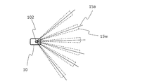
- FIG. 2 is a diagram showing a plurality of laser beams (solid lines) emitted from the LRF 102 of the moving body 10 for each step angle.
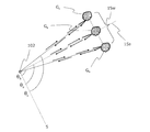
- FIG. 3 is a diagram for explaining a detection error of the laser beam 15w having a spread.
- FIG. 4 is a diagram for explaining that the spread laser beam 15w increases the detection error.
- FIG. 5 is a diagram for explaining that the actually existing object G real is detected as a larger object G virtual .
- FIG. 6A is a plan layout diagram schematically showing the position of a moving body that scans a certain moving environment.
- FIG. 6B is a diagram showing a map (map M) of the environment 200 shown in FIG. 6A.
- FIG. 7 is a diagram showing the mobile body 10 and the measurable region SA of the mobile body 10.
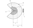
- FIG. 8A is a diagram showing the relationship between the measurable region SA and the partial region SB used by the moving body 10 when creating a map.
- FIG. 8B is a diagram showing the positional relationship between the moving body 10 and the object G when the moving body 10 moves and approaches the object G.
- FIG. 8C is a diagram showing the positional relationship between the moving body 10 and the object G when the moving body 10 further moves and approaches the object G.
- FIG. 9A is a diagram showing a measurable area SA of the moving body 10 at the time of creating a map.
- FIG. 9A is a diagram showing a measurable area SA of the moving body 10 at the time of creating a map.
- FIG. 9B is a diagram showing the positional relationship between the moving body 10 and the object G when the object G enters the measurable region SA.
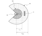
- FIG. 9C is a diagram showing an exclusion region SV set in the measurable region SA and selected partial regions SB-1 and SB-2.
- FIG. 9D is a diagram showing the positional relationship between the moving body 10 and the object G when the moving body 10 continues to move.
- FIG. 9E is a diagram showing the positional relationship between the moving body 10 and the object G when the intensity of the reflected light from the object G becomes equal to or less than the intensity threshold value ITH .
- FIG. 10 is a diagram showing a map 204M created by arranging point clouds acquired by the operation of the first example or the second example described above in the environment 200 in which the moving body 10 moves.
- FIG. 10 is a diagram showing a map 204M created by arranging point clouds acquired by the operation of the first example or the second example described above in the environment 200 in which the moving body 10 moves.
- FIG. 11 is a diagram showing a map creation processing flow in which the measurement range is limited.
- FIG. 12A is a diagram showing a first processing flow for selecting a partial region.
- FIG. 12B is a diagram showing a second processing flow for selecting a partial region.
- FIG. 13 is a list diagram for explaining the difference in the measurement area used by the moving body 10 at the time of creating the map and at the time of estimating the self-position.
- FIG. 14 is a diagram showing an outline of a control system for controlling the traveling of each AGV according to the present disclosure.
- FIG. 15 is a perspective view showing an example of an environment in which an AGV exists.
- FIG. 16 is a perspective view showing the AGV and the tow truck before being connected.
- FIG. 17 is a perspective view showing the connected AGV and the tow truck.
- FIG. 18 is an external view of an exemplary AGV according to this embodiment.
- FIG. 19A is a diagram showing a first hardware configuration example of the AGV.
- FIG. 19B is a diagram showing a second hardware configuration example of the AGV.
- FIG. 20 is a diagram showing a hardware configuration example of the operation management device.
- An "automated guided vehicle” means an automatic guided vehicle (AGV) that manually or automatically loads luggage into the main body, automatically travels to a designated place, and manually or automatically unloads.
- “Automated guided vehicles” include unmanned tow trucks and unmanned forklifts.
- unmanned means that no person is required to steer the vehicle, and does not exclude automatic guided vehicles carrying "people (eg, those who load and unload luggage)”.
- An "unmanned towing vehicle” is an untracked vehicle that automatically travels to a designated place by towing a trolley that manually or automatically loads and unloads luggage.
- An "unmanned forklift” is an untracked vehicle equipped with a mast that raises and lowers a fork for transferring luggage, automatically transfers the luggage to the fork, etc., and automatically travels to the designated place to perform automatic cargo handling work.
- a “trackless vehicle” is a vehicle that includes wheels and an electric motor or engine that rotates the wheels.
- a “moving body” is a device that carries a person or luggage to move, and includes a driving device such as a wheel, a two-legged or multi-legged walking device, or a propeller that generates a driving force (traction) for movement.
- a driving device such as a wheel, a two-legged or multi-legged walking device, or a propeller that generates a driving force (traction) for movement.
- the term “mobile” in the present disclosure includes mobile robots, service robots, and drones as well as automatic guided vehicles in the narrow sense.
- Autonomous driving includes traveling based on a command of a computer operation management system to which an automatic guided vehicle is connected by communication, and autonomous driving by a control device provided in the automated guided vehicle. Autonomous traveling includes not only traveling of an automated guided vehicle toward a destination along a predetermined route, but also traveling of following a tracking target. Further, the automatic guided vehicle may temporarily perform manual running based on the instruction of the operator.
- Automatic driving generally includes both “guided” driving and “guideless” driving, but in the present disclosure it means “guideless” driving.
- the "guide type” is a method in which derivatives are installed continuously or intermittently, and an automatic guided vehicle is guided by using the derivatives.
- the "guideless type” is a method of guiding without installing a derivative.
- the automatic guided vehicle according to the embodiment of the present disclosure includes a self-position estimation device and can travel in a guideless manner.
- the “position estimation device” is a device that estimates its own position on a map based on sensor data acquired by an external sensor such as a laser range finder.
- the "outside world sensor” is a sensor that senses the external state of a moving body.
- External world sensors include, for example, a laser range finder (also referred to as a range finder), a camera (or image sensor), a LIDAR (Light Detection and Langing), a millimeter wave radar, an ultrasonic sensor, and a magnetic sensor.
- the “inner world sensor” is a sensor that senses the internal state of a moving body.
- the internal sensor includes, for example, a rotary encoder (hereinafter, may be simply referred to as an “encoder”), an acceleration sensor, and an angular acceleration sensor (for example, a gyro sensor).
- SAM Simultaneous Localization and Mapping, which means that self-position estimation and mapping are performed at the same time.
- the external sensor is a laser range finder (LRF).
- LRF laser range finder
- LIDAR may be adopted.
- the mobile body 10 of the present disclosure includes a laser range finder 102 that scans the environment (around the mobile body 10) and periodically outputs scan data in the exemplary embodiment shown in FIG. 1A.
- the laser range finder 102 is abbreviated as "LRF102".
- the LRF102 is a device that measures a distance using a laser beam emitted from a laser element.
- the LRF102 periodically emits, for example, an infrared or visible laser beam to the surroundings to scan the environment.
- the laser beam is reflected, for example, on the surface of a structure such as a wall or a pillar, or an object placed on the floor.
- the LRF 102 receives the reflected light of the laser beam, calculates the distance to each reflection point, and outputs the measurement result data showing the position of each reflection point.
- the position of each reflection point reflects the arrival direction and distance of the reflected light.
- the measurement result data (scan data) is sometimes called “environmental measurement data” or “sensor data”.
- the LRF 102 employs, for example, a TOF (Time Of Flight) method or a phase difference method.
- the TOF method the LRF 102 calculates the time required for the laser beam to reciprocate from the difference between the time when the laser beam is emitted and the time when the reflected light is received. The product of the speed of light and the round trip time indicates the round trip distance to the reflection point. As a result, the LRF 102 can acquire data on the distance to the reflection point.
- the LRF 102 modulates the intensity of continuous light at a predetermined frequency and emits the light, and detects the phase difference between the modulated emitted light and the received reflected light.
- a phase difference occurs between the phase of the emitted light and the phase of the reflected light according to the round-trip distance (optical path length) to the reflection point.
- the LRF 102 can acquire data on the distance to the reflection point.
- the maximum phase delay can be detected for 360 degrees, that is, for one wavelength.
- the scan of the environment by the LRF102 is performed, for example, on an environment having an angle range of 135 degrees to the left and right (270 degrees in total) with respect to the front surface of the LRF 102.
- the LRF 102 emits a pulsed laser beam while changing the direction at each predetermined step angle in the horizontal plane, and detects the reflected light of each laser beam.
- the LRF102 measures the distance for each step angle by utilizing the relationship between the emitted laser beam and the reflected light. If the step angle is 0.3 degrees, measurement data of the distance to the reflection point in the direction determined by the angle for a total of 901 steps can be obtained.
- the scan of the surrounding space performed by the LRF102 is substantially parallel to the floor and is planar (two-dimensional). However, the LRF102 may perform a three-dimensional scan.
- the distance at which measurement is guaranteed for the LRF 102 is determined at the time of design.
- the LRF 102 can acquire distance data indicating the distance to a reflection point existing within a distance of, for example, 30 m.
- the start time of scanning in the range of 270 degrees may be referred to as “scan time” for convenience.
- scan time the time when the laser beam is emitted in the angle direction of -135 degrees is called “scan time”.
- a typical example of scan data can be represented by the position coordinates of each point that constitutes a point cloud acquired for each scan.
- the position coordinates of the points are defined by the local coordinate system that moves with the moving body 10.
- Such a local coordinate system may be referred to as a mobile coordinate system or a sensor coordinate system.
- the origin of the local coordinate system fixed to the moving body 10 is defined as the "position" of the moving body 10
- the orientation of the local coordinate system is defined as the "posture" of the moving body 10.
- the position and posture may be collectively referred to as a "pose”.
- scan data When displayed in polar coordinate system, scan data may consist of a set of numbers indicating the position of each point in "direction" and “distance” from the origin in the local coordinate system. However, if the reflected light is not detected, there is no point for that angle.
- the display of the polar coordinate system can be transformed into the display of the Cartesian coordinate system. In the following description, for the sake of simplicity, it is assumed that the scan data output from the LRF 102 is displayed in the Cartesian coordinate system.
- the moving body 10 shown in FIG. 1A can either create an environmental map (hereinafter referred to as "map") and move autonomously while referring to the created map. it can. However, it is not essential that the moving body 10 do both. In the present embodiment, it is sufficient that at least a map can be created.
- map environmental map
- the mobile body 10 includes a storage device 104 and a signal processing circuit 106.
- the storage device 104 stores and updates the map created from the scan data while accumulating the scan data at the time of creating the map, and stores the map created in advance at the time of autonomous movement. It should be noted that the number of stored maps may be multiple instead of one.
- the signal processing circuit 106 is, for example, a semiconductor integrated circuit, and may be a CPU (Central Processing Unit), an MPU (Micro Processing Unit), or an ASIC (Application Specific IC).
- the signal processing circuit 106 operates as a map creation device when creating a map, and operates as a position estimation device during autonomous movement after map creation.
- the signal processing circuit 106 arranges the point groups of the scan data acquired from the LRF 102 according to the angle and distance of irradiation with the laser beam. This gives a partial map of the scan range. Subsequently, the signal processing circuit 106 updates the partial map of the point cloud obtained by scanning at the next scan time using its position coordinates.
- the "position coordinates" referred to here can be expressed by relative coordinates based on the position where the scan data is acquired earlier, or absolute coordinates set by the user for convenience.
- the change in pose can be detected by using, for example, the odometry information of the moving body 10.
- the moving body 10 is an AGV having a plurality of driving wheels
- the distance and direction in which the moving body 10 has moved can be estimated by integrating the rotation speeds of the driving wheels or the number of rotations per unit time. it can.
- Information on the rotational speed of each drive wheel or the number of revolutions per unit time is sometimes called "odometry information".
- the moving body 10 may create a map while detecting a change in pose by SLAM technology using LRF102.
- the moving body 10 can also use the odometry information not only when creating a map but also when moving while estimating its own position.
- the mobile body 10 can estimate its own position using both the scan by the LRF 102 and the odometry information.
- a plurality of sets of points obtained by scanning at different scan times may include reflection points indicating substantially similar positions of the same object existing in the environment. If everything is reflected on the map as separate and independent points, the amount of map data will be very large. Therefore, in order to limit the amount of data, the signal processing circuit 106 may divide the map into meshes and limit the number of scan data so that one section of the mesh contains only one reflection point.
- the size of one compartment of the mesh can be, for example, 10 cm square in the actual environment.
- the signal processing circuit 106 matches the scan data acquired from the LRF 102 with the map read from the storage device 104, and estimates the pose of the moving body 10. This matching is called pattern matching or scan matching and can be performed according to various algorithms.
- a typical example of a matching algorithm is an Iterative Closest Point (ICP) algorithm.
- the map read from the storage device 104 may be a map created by the moving body 10 itself, or may be a map created by another device.
- the moving body 10 further includes a drive device 108, a travel control device 110, a communication circuit 112, and an input device 114.
- the drive device 108 is a device that generates a driving force for the moving body 10 to move.
- Examples of drive device 108 include wheels (drive wheels) rotated by an electric motor or engine, bipedal or multilegged walking devices operated by motors or other actuators.
- the wheel may be an omnidirectional wheel such as a Mecanum wheel.
- the moving body 10 may be a moving body moving in the air or underwater, or a hovercraft, in which case the driving device 108 includes a propeller rotated by a motor.
- the travel control device 110 operates the drive device 108 to control the movement conditions (speed, acceleration, movement direction, etc.) of the moving body 10.
- the travel control device 110 may move the moving body 10 along a predetermined travel route, or may move it according to a command given from the outside.
- the signal processing circuit 106 calculates an estimated value of the position and posture of the moving body 10 while the moving body 10 is moving or stopped.
- the travel control device 110 controls the travel of the moving body 10 with reference to this estimated value.
- the signal processing circuit 106 and the travel control device 110 may be referred to as a travel control device (control system) 120 as a whole.
- the travel control device 120 may be composed of a processor and a memory that stores a computer program that controls the operation of the processor.
- processors and memories can be implemented by one or more semiconductor integrated circuits.
- the communication circuit 112 is a circuit in which the mobile body 10 is connected to a communication network including an external management device, another mobile body, an operator's mobile terminal device, and the like to exchange data and / or commands.
- the communication circuit 112 may perform either wireless communication and / or wired communication.
- the input device 114 is a device that receives a user's instruction.
- the input device 114 can be used to receive the designation of the detection range (distance, angle range) of the point cloud used for map creation at the time of map creation described later.
- the input device 114 can also be used to receive input of commands related to movement conditions and travel routes.
- the input device 114 is, for example, an input terminal that receives an external command, or a physical button provided on the moving body 10. When the moving body 10 is provided with a touch panel display, the input device 114 may be a touch panel or a software button.
- a typical example of the storage device 104 described above is realized by a storage device mounted on the mobile body 10 and moving together with the mobile body 10.
- the storage device 104 is not limited to this example.
- the storage device 104 may be a storage device or database that is located outside the mobile body 10 and can be connected to the mobile body 10 by the communication circuit 112.
- scan data that can be used for creating a map is transmitted from the mobile body 10 to the storage device 104, a signal other than the mobile body 10 is transmitted.
- the processing circuit may create the map. That is, it is not essential that the moving body 10 creates a map. Further, it is also possible for a plurality of mobile bodies 10 to appropriately read necessary map data from a common storage device 104 and perform autonomous driving.
- FIG. 1B shows the configuration of an embodiment of the map creation system 300 according to the present disclosure.
- the map creation system 300 creates a map that the moving body 10 refers to in order to estimate its own position.
- the mapping system 300 has an LRF 102 and a signal processing circuit 106. These configurations and functions are the same as the configurations and functions of the LRF 102 and the signal processing circuit 106 provided in the mobile body 10 shown in FIG. 1A. However, the signal processing circuit 106 need only have a function of creating a map, and position estimation processing for autonomous driving is not essential.
- the mapping system 300 may be provided in one device such as the mobile body 10, or the LRF 102 and the signal processing circuit 106 may have separate housings as two devices. In the latter case, the devices need only be connected to each other by a communication line so that data can be transmitted and received.
- the signal processing circuit 106 may be realized by one PC, and the LRF 102 may be installed on a trolley that is manually moved. Then, the PC and the LRF 102 may be connected by wire or wirelessly.
- a storage device 104 for storing map data created by the signal processing circuit 106 may be appropriately provided.
- the signal processing circuit 106 and the storage device 104 may be the CPU 51 and the memory 52 of the operation management device 50, which will be described later with reference to FIGS. 14 and 20, respectively.
- the map creation system 300 temporarily stores the scan data acquired by the LRF 102 in a storage device such as a flash memory, connects the storage device to the signal processing circuit 106, and the signal processing circuit 106 creates a map. It can also include morphology.
- FIG. 2 schematically shows a plurality of laser beams (solid lines) for each step angle emitted from the LRF 102 of the moving body 10.
- the step angle is shown very large for convenience of explanation.
- the laser beam 15a will be focused on, but the same description applies to other laser beams.
- the emitted laser beam does not become perfectly parallel light even after passing through the collimated lens, and has a divergence angle that is not 0 degrees. Therefore, the cross section of the laser beam in the plane perpendicular to the optical axis becomes larger as it goes farther.
- the laser beam 15a is shown as a straight line in FIG. 2, the beam 15w having a spread is actually emitted.
- the shape of the beam 15w is only schematically shown. Since the scan of the surrounding space performed by the LRF 102 is substantially parallel to the floor surface in the present disclosure, the spread of the laser beam in the direction perpendicular to the floor surface is not considered.
- a laser beam having such a spread can cause a detection error in the direction in which the object exists.
- FIG. 3 is a diagram for explaining a detection error of the laser beam 15w having a spread. It is assumed that the laser beam is emitted from the LRF 102 in the direction of the angle ⁇ a. The angle is an angle calculated from an arbitrary reference line S. Assuming that the diameter is constant and sufficiently thin, the laser beam 15a will be emitted. The laser beam 15a is reflected only by the object Ga existing on the optical axis and returns to the LRF 102. The laser beam 15a is not reflected by the object Gb or the object Gc existing in the direction of the angle ⁇ b or the angle ⁇ c deviated from the optical axis.
- the LRF102 emits a spread laser beam 15w.
- the laser beam 15w is reflected not only by the object Ga existing in the direction of the angle ⁇ a, but also by the object Gb existing in the direction of the angle ⁇ b and the object Gc existing in the direction of the angle ⁇ c. That is, all the objects existing between the angles ⁇ b and ⁇ c are detected as being the objects existing in the direction of the angle ⁇ a. As a result, a detection error occurs.
- FIG. 4 is a diagram for explaining that the spread laser beam 15w increases the detection error.
- FIG. 5 is a diagram for explaining that the actually existing object G real is detected as a larger object G virtual . It is assumed that the scan is performed along the direction from -X to + X in the figure. First, the first reflection of G real is detected at the beam end on the + X side of the laser beam 15w-1 having a width. As a result, the object Greal is detected to have an end at a position extending by the radius of the beam on the ⁇ X side of the actual object. The scan is continued and the last reflection of the object Greal is detected at the -X side beam end of the wide laser beam 15w-2. As a result, it is detected that the object G real has an end portion at a position extended by the radius of the beam on the + X side of the actual object. That is, the actual object G real is detected as a larger object G virtual . As described with reference to FIG. 4, the detection error becomes larger as the reflection occurs at a greater distance, and the object G virtual is detected larger than the actual object G real .
- FIG. 6A is a plan layout diagram schematically showing an example of an environment 200 in which the moving body 10 moves. Environment 200 is part of a wider environment.
- the thick straight line indicates, for example, the fixed wall 202 of the building. It is assumed that the moving body 10 scans at the position shown in FIG. 6A to create a map.
- FIG. 6B shows a map 202M created by arranging the acquired point clouds.
- the fixed wall 202 of the building is shown by a solid line.
- the detection error of the position of each point included in the point groups 202M-1, 202M-2 and 202M-3 becomes larger as the position is farther from the moving body 10, and the distortion of the map becomes larger. The presence of such distortion affects the running accuracy of another moving body 10 that autonomously travels with reference to the map.
- the inventor of the present application has studied to improve the accuracy of the created map and to make it possible to estimate the self-position more accurately during autonomous driving.
- the inventor of the present application considered that the detection error of the laser beam 15w can actually affect the accuracy of the map when the intensity of the reflected light received from a distance is large. For example, when specular reflection or retroreflection of the laser beam 15w occurs on the surface of a distant object, the intensity of the reflected light increases. If specular reflection or retroreflection does not occur, even if the outer edge of the spread laser beam 15w is reflected on the surface of a distant object, the intensity of the reflected light is small and it is treated as noise, and the detection error of the position of the reflection point is It does not occur substantially.
- the mapping system 300 (FIG. 1B) according to the present disclosure includes an LRF 102 and a signal processing circuit 106.
- the LRF102 emits a laser beam while changing the angle within the first angle range (for example, within the range of 270 degrees) to acquire the reflected light. Then, the LRF 102 uses the relationship between the emitted laser beam and the reflected light to acquire distance data indicating the distance to the reflection point existing within the first measurable distance (for example, within 30 m) for each angle. ..
- An example of the "relationship" referred to here is, for example, the time difference between the emission time of the laser beam and the detection time of the reflected light, or the phase difference between the phase of the emitted laser beam and the phase of the reflected light.
- the signal processing circuit 106 selects one or more subregions smaller than the measurable region from the measurable regions defined by the first angle range and the first distance, and the reflection included in the one or more subregions. Create a map using distance data that indicates the distance to a point. There are typically the following two examples of one or more subregions that are smaller than the measurable region.
- a partial region defined by a first angular range (eg, a range of 270 degrees) and at least one second distance (eg, 10 m) shorter than the first distance is selected.
- a first angular range eg, a range of 270 degrees
- second distance eg, 10 m
- the second example assumes that a map is created using the reflected light from the remaining angle range excluding a part of the angle range.
- a threshold value (intensity threshold value) of the intensity of the reflected light is set according to the distance at which the reflection point exists. When strong reflected light is obtained from the vicinity of the first distance (30 m), the detection error becomes large although it can be used as scan data.
- the signal processing circuit 106 compares the intensity threshold value according to the distance to the reflection point of the object with the intensity of the reflected light, and when the intensity of the reflected light is larger than the intensity threshold value, the direction in which the reflected light arrives is determined. Exclude the included angle range. Then, the signal processing circuit 106 creates a map using the reflection points existing in at least one remaining second angle range.
- the second angle range can be variable. This is because the direction in which the strong reflected light is received can change as the moving body 10 travels.
- the signal processing circuit 106 continues to compare the intensity threshold according to the distance to the reflection point of the ever-changing object with the intensity of the reflected light. When the intensity of the reflected light becomes equal to or less than the intensity threshold value, the signal processing circuit 106 incorporates the range below the intensity threshold value into the above-mentioned second angle range and creates a map using the reflection points existing in the second angle range. To do.
- FIG. 7 shows the mobile body 10 and the measurable region SA of the mobile body 10.
- the measurable region SA is defined by the angle range ⁇ and the maximum measurement distance L MAX .
- the basic moving body 10 creates a map using the reflection points detected in the measurable area SA while moving in the direction of the white arrow, or the reflection points and the map detected in the measurable area SA. Is collated and autonomous movement is performed.
- the first example is an example in which the detection area of the reflection point used for creating the map is fixed to a smaller area.
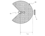
- FIG. 8A shows the relationship between the measurable region SA and the partial region SB used by the moving body 10 when creating a map.
- the partial region SB is smaller than the measurable region SA. More specifically, the partial region SB is defined by the same angle range ⁇ as the measurable region SA and the distance threshold L TH smaller than the maximum measurement distance L MAX of the measurable region SA.
- the moving body 10 creates a map using the reflection points posted in the partial area SB.
- the object G shown in FIG. 8A will be described as an example.
- the object G is, for example, a shelf installed in the environment. In the following description, the distance will be focused on on the premise that the object G exists in the angle range ⁇ .
- FIG. 8B shows the positional relationship between the moving body 10 and the object G when the moving body 10 moves and approaches the object G.
- the LRF 102 also measures the reflection points in a region included in the measurable region SA but not in the partial region SB (a region outside the partial region SB). Therefore, the output of the LRF 102 includes the distance to the reflection point on the object G.
- the signal processing circuit 106 does not create a map using the reflection points on the object G located at a position farther than the distance threshold LTH .
- FIG. 8C shows the positional relationship between the moving body 10 and the object G when the moving body 10 further moves and approaches the object G.
- the signal processing circuit 106 detects that the distance to the reflection point on the object G is equal to or less than the distance threshold value LTH, the signal processing circuit 106 creates a map using the distance data to the reflection point.
- a point cloud 204 showing the position of the reflection point on the surface of the object G on the moving body 10 side is shown.
- the above-mentioned processing means that the signal processing circuit 106 selects a partial region SB from the measurable region SA and creates a map by using the reflection points from the region included in the partial region SB. As a result, the detection error (distortion) that may be included in the position of the reflection point farther than the distance threshold L TH can be suppressed to be smaller.
- the method of setting the distance threshold value LTH is arbitrary. For example, even if a predetermined distance threshold value LTH is stored as selection reference data in the storage device 104 and the signal processing circuit 106 reads the selection reference data from the storage device 104 and sets it as the distance threshold value LTH. Good.
- the user may input a value via the input device 114, and the signal processing circuit 106 may set the value as the distance threshold LTH . That is, the input device 114 can accept the designation of the partial area from the user.
- the distance threshold L TH can be a distance less than 25 m, such as 20 m, 15 m or 10 m, where the maximum measurement distance L MAX is 30 m.
- the second example is an example in which the detection area of the reflection point used for creating the map is variably set to a smaller area.
- FIG. 9A shows the measurable region SA of the moving body 10 at the time of map creation.
- the measurable area SA at this time is the same as the example shown in FIG.
- the relative distance between the moving body 10 and the object G becomes smaller.
- the relative distance becomes within the maximum measurement distance L MAX , and the object G enters the measurable region SA.
- FIG. 9B shows the positional relationship between the moving body 10 and the object G when the object G enters the measurable region SA. As described with reference to FIG. 5, in FIG. 9B, it is schematically shown that the actual object G shown by the diagonal line is detected as a larger object as shown by the broken line.
- the signal processing circuit 106 acquires the intensity data of the reflected light of the object G from the LRF 102 for each step angle together with the distance data and the intensity data indicating the intensity of the reflected light.
- the signal processing circuit 106 detects that the object G exists in the measurable region SA by using the distance data. Further, the signal processing circuit 106 compares the intensity data with the predetermined intensity threshold value ITH for each detected distance, and determines whether or not the intensity of the reflected light of the object G exceeds the predetermined intensity threshold value ITH .
- the intensity threshold value ITH is a threshold value related to the intensity of reflected light prepared in advance.
- the storage device 104 stores selection reference data in which the distance and the intensity threshold value ITH are associated with each other.
- the selection criterion data may be stored as a function of the distance and the intensity threshold value ITH , or may be stored as a table in which each of the values of the plurality of distances and the intensity threshold value ITH are associated with each other.
- the signal processing circuit 106 reads the selection reference data from the storage device 104 and holds the intensity threshold value ITH according to the distance.
- the intensity threshold value ITH of the maximum measurement distance L MAX (example: 30 m) is set to a value smaller than the reflection intensity detected when specular reflection or retroreflection occurs.
- the signal processing circuit 106 indicates that the object G exists in the measurable region SA and that the intensity of the reflected light of the object G exceeds the intensity threshold value ITH determined according to the distance to the object G. Upon detection, the signal processing circuit 106 sets a part of the measurable region SA including the reflection point of the object G as the exclusion region SV. Then, the signal processing circuit 106 selects an area other than the exclusion area SV in the measurable area SA as an area for creating a map. For example, by adopting the function of the intensity threshold value ITH , which is larger as the distance is smaller and smaller as the distance is larger, the region including the reflection point having a large distance but a high intensity can be set as the exclusion region SV.
- FIG. 9C illustrates the exclusion region SV in the measurable region SA and the selected partial regions SB-1 and SB-2.
- the signal processing circuit 106 sets at least a region defined by the angle range ⁇ SV in which the object G is detected and the maximum measurement distance L MAX as the exclusion region SV.
- the signal processing circuit 106 does not use the reflection points in the exclusion region SV for creating the map, but uses the reflection points in the partial regions SB-1 and SB-2 for creating the map.
- the partial region SB-1 is defined by an angle range ⁇ B-1 smaller than the angle range ⁇ and a maximum measurement distance L MAX .
- the partial region SB-2 is defined by an angle range ⁇ B-2 smaller than the angle range ⁇ and a maximum measurement distance L MAX .
- two subregions SB-1 and SB-2 are illustrated as the remaining regions, but the number of subregions may be one or three or more. At least one subregion may be selected.
- the reflected light acquired from the partial regions SB-1 and SB-2 may also include the reflected light from the position of the maximum measurement distance LMAX .
- the intensity of the reflected light is so small that it can be treated as noise and is not used for creating a map. Therefore, the partial regions SB-1 and SB-2 may extend to the maximum measurement distance LMAX .
- FIG. 9D shows the positional relationship between the moving body 10 and the object G when the moving body 10 continues to move. Even after the exclusion region SV is set, the signal processing circuit 106 continuously acquires the distance data and the intensity data of the object G from the LRF 102. The signal processing circuit 106 acquires the intensity threshold value ITH corresponding to the distance of the current object G by using the distance data and the selection reference data, and compares the intensity data with the intensity threshold value ITH .
- FIG. 9D shows an example in which the intensity data is still slightly larger than the intensity threshold ITH . For reference, the position where the intensity data and the intensity threshold value ITH substantially coincide with each other is indicated by a broken line arc in contact with the object G.
- FIG. 9E shows the positional relationship between the moving body 10 and the object G when the intensity of the reflected light from the object G becomes equal to or less than the intensity threshold value ITH .
- the distance between the moving body 10 and the object G at this time is shown as the distance LSV .
- the intensity threshold value ITH at this time is also obtained according to the distance to the reflection point to which the intensity data is given.
- the signal processing circuit 106 detects that the intensity data is equal to or less than the intensity threshold value ITH
- the signal processing circuit 106 sets a partial region SB-3 defined by an angle range ⁇ SV and a distance L SV shorter than the maximum measurement distance L MAX. , Newly selected as a detection area for reflection points used to create a map.
- the angle range ⁇ SV of the partial region SB-3 is a range other than the angle ranges ⁇ B-1 and ⁇ B-2 in the total angle range ⁇ .
- a point cloud 204 showing the position of the reflection point on the surface of the object G on the moving body 10 side is shown.
- the reason for selecting the partial region SB-3 to be additionally set is that the object G is reflected on the map when the detection error of the object G is within the allowable range.
- the exclusion region SV dynamically changes. Without the additional processing of the angle range described above, the area where the object exists is always set to the exclusion area SV, and the object is not reflected on the map.
- the intensity of the reflected light is equal to or less than the intensity threshold value ITH , it can be considered that the relative distance between the moving body 10 and the object G is reduced and the detection error of the object G is within an acceptable range. If the object G is reflected on the map at that time, the accuracy of the map can be guaranteed.
- the exclusion region SV was first set and the remaining partial regions SB-1 and SB-2 were determined. However, it is not necessary to set the exclusion region SV at that time.
- the signal processing circuit 106 detects that the object G has simply entered the measurable region SA, the region where the intensity of all the reflected light including the object G is equal to or less than the intensity threshold value according to the distance is set as the partial region SB-. It may be selected as 1 and SB-2.
- FIG. 10 shows a map 204M created by arranging the point clouds acquired by the operation of the first example or the second example described above in the environment 200 in which the moving body 10 moves. Similar to FIG. 6B, the fixed wall 202 of the building is shown by a solid line for reference. Unlike the example of FIG. 6B, due to the operation of the first or second example described above, the reflection point at a position farther than the distance threshold L TH is not used for creating the map, and the reflection point at a position close to the distance threshold L TH or less is not used. Reflection points are used to create the map. As a result, the detection error of the position of each point included in the point groups 204M-1 and 204M-2 becomes sufficiently small. It is assumed that the point group 204M-3 was acquired by performing the operations of the first example or the second example described above before the moving body 10 reached the position shown in FIG. 6A.
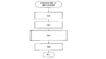
- FIG. 11 is a diagram showing a map creation processing flow in which the measurement range is limited.
- step S10 the signal processing circuit 106 sends a command to the LRF 102 to start emitting the laser beam.
- a laser beam is emitted at every step angle of 0.3 degrees from ⁇ 135 degrees to +135 degrees to scan the surrounding environment.
- step S12 the signal processing circuit 106 acquires distance data for each step angle from the LRF 102.
- the distance data is calculated by using the relationship between the laser beam emitted by the LRF 102 and the reflected light received by the LRF 102. Since the "relationship" is as described above, the description thereof will be omitted again.
- the signal processing circuit 106 may receive the position coordinate data and the distance data of a set of reflection points from the LRF 102 for each step angle, or may receive the orientation data and the distance data of the reflection points from the LRF 102.
- the orientation is known because it changes with each step angle. If the obtained distance data are ordered and arranged, it is not essential to include the orientation data.
- step S14 the signal processing circuit 106 selects one or more subregions from the measurable regions.
- a subregion is a subset of a measurable region.
- step S16 the signal processing circuit 106 creates a map using the distance data included in the selected partial region, and ends the processing.
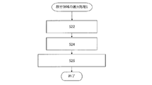
- FIG. 12A shows a first processing flow for selecting a partial region.
- the first processing flow corresponds to the processing of the first example described above.
- step S22 the signal processing circuit 106 reads the selection reference data from the storage device 104.
- the selection reference data is a numerical value indicating the distance threshold value LTH .
- step S24 the signal processing circuit 106 acquires all distance data in the measurable region SA from the LRF 102.
- step S26 the signal processing circuit 106 selects a region defined by the angle range ⁇ and the distance threshold L TH as the partial region SB.
- the distance data having the distance threshold value LTH or less is selected from all the distance data and used for creating the map.
- the angle range ⁇ is the same as the scan range of the LRF 102 and is known.
- FIG. 12B shows a second processing flow for selecting a partial region.
- the second processing flow corresponds to the processing of the second example described above.
- step S32 the signal processing circuit 106 acquires selection reference data from the storage device 104.
- the selection reference data is a numerical value indicating the intensity threshold value ITH according to the distance.
- step S34 the signal processing circuit 106 acquires distance data and reflected light intensity data from the LRF 102 for each scan angle.
- step S36 the signal processing circuit 106 determines the scan angle of the intensity threshold I TH in the intensity data ⁇ that distance at a distance.
- step S38 the signal processing circuit 106 determines the region including the determined scan angle as the exclusion region SV, and selects the region other than the exclusion region SV in the measurable region SA as the partial region.
- the signal processing circuit 106 selects one or more subregions SB-1 and SB-2. The reflection points in the selected subregion are used to create the map. Then, with the continuous movement of the moving body 10, the signal processing circuit 106 executes the following steps S40 and 42.
- step S40 the signal processing circuit 106, among the reflection points in the exclusion zone SV, to determine the reflection point as a intensity threshold I TH in the intensity data ⁇ that distance at a distance.
- step S42 the signal processing circuit 106 additionally selects a region including the determined reflection point as a partial region.
- the signal processing circuit 106 selects the partial region SB-3 in addition to the partial regions SB-1 and SB-2. Reflection points within the selected subregion SB-3 are further utilized in the creation of the map.
- FIG. 13 is a list diagram for explaining the difference in the measurement area used by the moving body 10 at the time of creating the map and at the time of estimating the self-position.
- the most significant difference is that the (first example described above, FIG. 12A) example using a distance threshold L TH subregion SB utilized in, from the measurement area SA LRF102 used when the mobile estimates the self-position Is also narrow.
- the sum of the partial regions SB-n (integer of n: 1 or more) used in the example using the intensity threshold value ITH (second example described above, FIG. 12B) is when the moving body estimates its own position. It is narrower than the maximum measurement area SA of the LRF102 used for the above. Since the detection error of the position of the reflection point in the selected partial region is within the allowable range, it is possible to improve the accuracy of the created map by creating a map using the reflection point.
- an automatic guided vehicle is given as an example of a moving body.
- the automatic guided vehicle will be described as "AGV” using abbreviations.
- the reference code “10” will be attached to the “AGV” as well as the moving body 10.
- the component corresponding to the storage device 104 is the “memory” described later, and the component corresponding to the signal processing circuit 106 is the “microcomputer 14a” and the “position estimation device 14e” described later, or the “chip circuit 14g” including these. ".
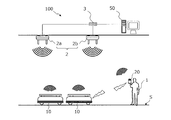
- FIG. 14 shows a basic configuration example of the exemplary mobile management system 100 according to the present disclosure.
- the mobile body management system 100 includes at least one AGV 10 and an operation management device 50 that manages the operation of the AGV 10.
- FIG. 14 also shows a terminal device 20 operated by the user 1.
- the AGV10 is an automatic guided vehicle capable of "guideless” traveling that does not require a derivative such as a magnetic tape for traveling.
- the AGV 10 can perform self-position estimation and transmit the estimation result to the terminal device 20 and the operation management device 50.
- the AGV 10 can automatically travel in the environment S according to a command from the operation management device 50.
- the operation management device 50 is a computer system that tracks the position of each AGV10 and manages the traveling of each AGV10.
- the operation management device 50 may be a desktop PC, a notebook PC, and / or a server computer.
- the operation management device 50 communicates with each AGV 10 via the plurality of access points 2. For example, the operation management device 50 transmits the coordinate data of the position where each AGV10 should go next to each AGV10.
- Each AGV 10 periodically transmits data indicating its position and orientation to the operation management device 50, for example, every 250 milliseconds. When the AGV 10 reaches the instructed position, the operation management device 50 further transmits the coordinate data of the position to be next.
- the AGV 10 can also travel in the environment S in response to the operation of the user 1 input to the terminal device 20.
- An example of the terminal device 20 is a tablet computer.
- FIG. 15 shows an example of the environment S in which three AGVs 10a, 10b and 10c exist. It is assumed that both AGVs are traveling in the depth direction in the figure. The AGVs 10a and 10b are transporting the load placed on the top plate. The AGV10c follows the front AGV10b and travels. For convenience of explanation, reference numerals 10a, 10b and 10c have been added in FIG. 15, but will be referred to as “AGV10” below.
- the AGV10 can also transport the luggage by using a towing trolley connected to itself.
- FIG. 16 shows the AGV 10 and the tow truck 5 before being connected. Casters are provided on each foot of the tow truck 5.
- the AGV 10 is mechanically connected to the towing carriage 5.
- FIG. 17 shows the connected AGV 10 and the tow truck 5.
- the AGV 10 travels, the towing carriage 5 is towed by the AGV 10.
- the AGV 10 can carry the load placed on the towing trolley 5.
- connection method between the AGV 10 and the towing carriage 5 is arbitrary. An example will be described here.
- a plate 6 is fixed to the top plate of the AGV 10.
- the tow truck 5 is provided with a guide 7 having a slit.
- the AGV 10 approaches the towing carriage 5 and inserts the plate 6 into the slit of the guide 7.
- the AGV 10 penetrates the plate 6 and the guide 7 with an electromagnetic lock type pin (not shown) to lock the electromagnetic lock.
- an electromagnetic lock type pin not shown
- Each AGV 10 and the terminal device 20 can be connected to each other on a one-to-one basis, for example, and can perform communication conforming to the Bluetooth (registered trademark) standard.
- Each AGV 10 and the terminal device 20 can also perform Wi-Fi (registered trademark) compliant communication using one or a plurality of access points 2.
- the plurality of access points 2 are connected to each other via, for example, a switching hub 3.
- FIG. 14 shows two access points 2a and 2b.
- the AGV10 is wirelessly connected to the access point 2a.
- the terminal device 20 is wirelessly connected to the access point 2b.
- the data transmitted by the AGV 10 is received by the access point 2a, then transferred to the access point 2b via the switching hub 3, and transmitted from the access point 2b to the terminal device 20. Further, the data transmitted by the terminal device 20 is received by the access point 2b, then transferred to the access point 2a via the switching hub 3, and transmitted from the access point 2a to the AGV10. As a result, bidirectional communication between the AGV 10 and the terminal device 20 is realized.
- the plurality of access points 2 are also connected to the operation management device 50 via the switching hub 3. As a result, bidirectional communication is also realized between the operation management device 50 and each AGV 10.
- a map in the environment S is created so that the AGV 10 can run while estimating its own position.
- the AGV10 is equipped with a position estimation device and an LRF102, and a map can be created by using the output of the LRF102.
- the AGV10 shifts to the data acquisition mode by the operation of the user.
- the AGV 10 starts acquiring sensor data using the LRF 102.
- the position estimation device stores the sensor data in the storage device.
- the sensor data stored in the storage device is transmitted to the external device.
- the external device is, for example, a computer having a signal processing processor and having a mapping computer program installed.
- the signal processor of the external device superimposes the sensor data obtained for each scan.
- a map of the environment S can be created by repeating the process of superimposing the signal processing processor.
- the map is processed using the above-mentioned map processing device 300 (see FIG. 10).
- the device 300 creates data indicating the position of a specific area selected from the map.
- the external device transmits the processed map data to the AGV10.
- the AGV10 stores the processed map data in an internal storage device.
- the external device may be the operation management device 50 or another device.
- the AGV 10 may create and process the map instead of the external device.
- a circuit such as an AGV10 microcontroller unit (microcomputer) may perform the processing performed by the signal processing processor of the external device described above.
- a circuit such as an AGV10 microcontroller unit (microcomputer) may perform the processing performed by the signal processing processor of the external device described above.
- the movement in the environment S for acquiring the sensor data can be realized by the AGV 10 traveling according to the operation of the user.
- the AGV 10 wirelessly receives a travel command from the user via the terminal device 20 instructing the user to move in each direction of front, back, left, and right.
- the AGV10 travels back and forth and left and right in the environment S according to a travel command to create a map.
- the map may be created by traveling in the environment S from front to back and left and right according to a control signal from the control device.
- Sensor data may be acquired by a person pushing the measuring trolley equipped with the LRF 102.
- the number of AGVs may be one.
- the user 1 can use the terminal device 20 to select one AGV10 from the plurality of registered AGVs and have the user 1 create a map of the environment S.
- each AGV10 can automatically travel while estimating its own position using the map.
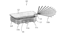
- FIG. 18 is an external view of an exemplary AGV 10 according to this embodiment.
- the AGV 10 has two drive wheels 11a and 11b, four casters 11c, 11d, 11e and 11f, a frame 12, a transfer table 13, a travel control device 14, and an LRF 102.
- the two drive wheels 11a and 11b are provided on the right side and the left side of the AGV 10, respectively.
- the four casters 11c, 11d, 11e and 11f are arranged at the four corners of the AGV10.
- the AGV10 also has a plurality of motors connected to the two drive wheels 11a and 11b, but the plurality of motors are not shown in FIG. Further, FIG.
- the travel control device 14 is a device that controls the operation of the AGV 10, and mainly includes an integrated circuit including a microcomputer (described later), electronic components, and a substrate on which they are mounted.
- the travel control device 14 performs data transmission / reception and preprocessing calculation with the terminal device 20 described above.
- the LRF 102 is an optical device that measures the distance to a reflection point by emitting, for example, an infrared laser beam 15a and detecting the reflected light of the laser beam 15a.
- the LRF102 of the AGV10 emits a pulsed laser beam 15a in a space within a range of 135 degrees to the left and right (270 degrees in total) with respect to the front surface of the AGV10, for example, while changing the direction every 0.25 degrees. Then, the reflected light of each laser beam 15a is detected.
- the scan of the surrounding space performed by the LRF 102 is substantially parallel to the floor surface and is planar (two-dimensional). However, the LRF 102 may perform a height scan.
- the AGV10 can create a map of the environment S.
- the map may reflect the placement of walls, pillars and other structures around the AGV, and objects placed on the floor.
- the map data is stored in a storage device provided in the AGV10.
- the position and posture of the AGV 10, that is, the pose (x, y, ⁇ ) may be simply referred to as “position” below.
- the travel control device 14 compares the measurement result of the LRF 102 with the map data held by the vehicle, and estimates its current position.
- the map data may be map data created by another AGV10.
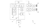
- FIG. 19A shows a first hardware configuration example of the AGV10.
- FIG. 19A also shows a specific configuration of the travel control device 14.
- the AGV 10 includes a travel control device 14, an LRF 102, two motors 16a and 16b, a drive device 17, and wheels 11a and 11b.
- the travel control device 14 includes a microcomputer 14a, a memory 14b, a storage device 14c, a communication circuit 14d, and a position estimation device 14e.
- the microcomputer 14a, the memory 14b, the storage device 14c, the communication circuit 14d, and the position estimation device 14e are connected by a communication bus 14f, and data can be exchanged with each other.
- the LRF 102 is also connected to the communication bus 14f via a communication interface (not shown), and transmits the measurement data as the measurement result to the microcomputer 14a, the position estimation device 14e and / or the memory 14b.
- the microcomputer 14a is a processor or a control circuit (computer) that performs calculations for controlling the entire AGV 10 including the travel control device 14.
- the microcomputer 14a is a semiconductor integrated circuit.
- the microcomputer 14a transmits a PWM (Pulse Width Modulation) signal, which is a control signal, to the drive device 17 to control the drive device 17 and adjust the voltage applied to the motor.
- PWM Pulse Width Modulation
- One or more control circuits that control the drive of the left and right motors 16a and 16b may be provided independently of the microcomputer 14a.
- the motor drive device 17 may include two microcomputers that control the drive of the motors 16a and 16b, respectively.
- the memory 14b is a volatile storage device that stores a computer program executed by the microcomputer 14a.
- the memory 14b can also be used as a work memory when the microcomputer 14a and the position estimation device 14e perform calculations.
- the storage device 14c is a non-volatile semiconductor memory device.
- the storage device 14c may be a magnetic recording medium typified by a hard disk or an optical recording medium typified by an optical disk.
- the storage device 14c may include a head device for writing and / or reading data to any recording medium and a control device for the head device.
- the storage device 14c stores the map M of the traveling environment S and the data (traveling route data) R of one or a plurality of traveling routes.
- the map M is created by operating the AGV 10 in the map creation mode and stored in the storage device 14c.
- the travel route data R is transmitted from the outside after the map M is created.
- the map M and the travel route data R are stored in the same storage device 14c, but may be stored in different storage devices.
- the AGV 10 receives the travel route data R indicating the travel route from the tablet computer.
- the traveling route data R at this time includes marker data indicating the positions of a plurality of markers.
- the "marker” indicates a passing position (via point) of the traveling AGV 10.
- the travel route data R includes at least the position information of the start marker indicating the travel start position and the end marker indicating the travel end position.
- the travel route data R may further include the position information of the markers of one or more intermediate waypoints. When the traveling route includes one or more intermediate waypoints, the route from the start marker to the end marker via the traveling waypoints in order is defined as the traveling route.
- the data of each marker may include, in addition to the coordinate data of the marker, the data of the direction (angle) and the traveling speed of the AGV 10 until the movement to the next marker.
- the data of each marker is the acceleration time required for acceleration until the traveling speed is reached, and / or ,
- the data of the deceleration time required for deceleration from the traveling speed to the stop at the position of the next marker may be included.
- the operation management device 50 may control the movement of the AGV 10 instead of the terminal device 20. In that case, the operation management device 50 may instruct the AGV 10 to move to the next marker each time the AGV 10 reaches the marker. For example, the AGV 10 receives from the operation management device 50 the coordinate data of the target position to be headed next, or the data of the distance to the target position and the angle to be traveled as the travel route data R indicating the travel route.
- the AGV10 can travel along the stored travel route while estimating its own position using the created map and the sensor data output by the LRF 102 acquired during travel.
- the communication circuit 14d is, for example, a wireless communication circuit that performs wireless communication conforming to the Bluetooth® and / or Wi-Fi® standard. Both standards include wireless communication standards using frequencies in the 2.4 GHz band. For example, in the mode in which the AGV 10 is run to create a map, the communication circuit 14d performs wireless communication conforming to the Bluetooth (registered trademark) standard and communicates with the terminal device 20 on a one-to-one basis.
- Bluetooth registered trademark
- the position estimation device 14e performs a map creation process and a self-position estimation process during traveling.
- the position estimation device 14e can create a map of the environment S based on the position and orientation of the AGV 10 and the scan result of the LRF 102.
- the position estimation device 14e receives the sensor data from the LRF 102, and also reads the map M and the position data of the specific area stored in the storage device 14c.
- the local map data (sensor data) created from the scan result of LRF102 is matched with a wider range of map M to identify the self-position (x, y, ⁇ ) on the map M.
- the position estimation device 14e generates "reliability" data indicating the degree to which the local map data matches the map M.
- the self-position (x, y, ⁇ ) and reliability data can be transmitted from the AGV 10 to the terminal device 20 or the operation management device 50.
- the terminal device 20 or the operation management device 50 can receive the self-position (x, y, ⁇ ) and reliability data and display them on the built-in or connected display device.
- the microcomputer 14a and the position estimation device 14e are considered to be separate components, but this is an example. It may be one chip circuit or a semiconductor integrated circuit capable of independently performing each operation of the microcomputer 14a and the position estimation device 14e.
- FIG. 19A shows a chip circuit 14g including the microcomputer 14a and the position estimation device 14e.
- the microcomputer 14a and the position estimation device 14e are provided separately and independently will be described.
- the two motors 16a and 16b are attached to the two wheels 11a and 11b, respectively, to rotate each wheel. That is, the two wheels 11a and 11b are driving wheels, respectively.
- the motor 16a and the motor 16b are described as being motors for driving the right wheel and the left wheel of the AGV 10, respectively.
- the drive device 17 has motor drive circuits 17a and 17b for adjusting the voltage applied to each of the two motors 16a and 16b.
- Each of the motor drive circuits 17a and 17b includes a so-called inverter circuit.
- the motor drive circuits 17a and 17b turn on or off the current flowing through each motor by the PWM signal transmitted from the microcomputer 14a or the microcomputer in the motor drive circuit 17a, thereby adjusting the voltage applied to the motor.
- FIG. 19B shows a second hardware configuration example of the AGV10.
- the second hardware configuration example differs from the first hardware configuration example (FIG. 19A) in that it has a laser positioning system 14h and that the microcomputer 14a is connected to each component on a one-to-one basis. To do.
- the laser positioning system 14h has a position estimation device 14e and an LRF 102.
- the position estimator 14e and LRF102 are connected, for example, by an Ethernet® cable. Each operation of the position estimation device 14e and the LRF102 is as described above.
- the laser positioning system 14h outputs information indicating the pose (x, y, ⁇ ) of the AGV 10 to the microcomputer 14a.
- the microcomputer 14a has various general-purpose I / O interfaces or general-purpose input / output ports (not shown).
- the microcomputer 14a is directly connected to other components in the travel control device 14, such as the communication circuit 14d and the laser positioning system 14h, via the general-purpose input / output port.
- the AGV 10 in the embodiment of the present disclosure may include a safety sensor such as an obstacle detection sensor and a bumper switch (not shown).
- a safety sensor such as an obstacle detection sensor and a bumper switch (not shown).
- FIG. 20 shows a hardware configuration example of the operation management device 50.
- the operation management device 50 includes a CPU 51, a memory 52, a position database (position DB) 53, a communication circuit 54, a map database (map DB) 55, and an image processing circuit 56.
- the CPU 51, the memory 52, the position DB 53, the communication circuit 54, the map DB 55, and the image processing circuit 56 are connected by a communication bus 57, and data can be exchanged with each other.
- the CPU 51 is a signal processing circuit (computer) that controls the operation of the operation management device 50.
- the CPU 51 is a semiconductor integrated circuit.
- the memory 52 is a volatile storage device that stores a computer program executed by the CPU 51.
- the memory 52 can also be used as a work memory when the CPU 51 performs an operation.
- the position DB 53 stores position data indicating each position that can be a destination of each AGV 10.
- the location data can be represented, for example, by the coordinates virtually set in the factory by the manager.
- the location data is determined by the administrator.
- the communication circuit 54 performs wired communication conforming to, for example, an Ethernet (registered trademark) standard.
- the communication circuit 54 is connected to the access point 2 (FIG. 14) by wire, and can communicate with the AGV 10 via the access point 2.
- the communication circuit 54 receives data to be transmitted to the AGV 10 from the CPU 51 via the bus 57. Further, the communication circuit 54 transmits the data (notification) received from the AGV 10 to the CPU 51 and / or the memory 52 via the bus 57.
- the map DB 55 stores map data of the inside of a factory or the like on which the AGV 10 travels and position data of a specific area.
- the data format does not matter as long as the map has a one-to-one correspondence with the position of each AGV10.
- the map stored in the map DB 55 may be a map created by CAD.
- the operation management device 50 can determine the route of the AGV 10 so that the AGV 10 bypasses the specific area, for example.
- the position DB 53 and the map DB 55 may be built on a non-volatile semiconductor memory, a magnetic recording medium typified by a hard disk, or an optical recording medium typified by an optical disk.
- the image processing circuit 56 is a circuit that generates video data displayed on the monitor 58.
- the image processing circuit 56 operates exclusively when the administrator operates the operation management device 50. In this embodiment, further detailed description will be omitted.
- the monitor 58 may be integrated with the operation management device 50. Further, the CPU 51 may perform the processing of the image processing circuit 56.
- the above-mentioned comprehensive aspect may be realized by a system, a method, an integrated circuit, a computer program, or a recording medium. Alternatively, it may be realized by any combination of systems, devices, methods, integrated circuits, computer programs, and recording media.
- the moving body of the present disclosure can be suitably used for moving and transporting items such as luggage, parts, and finished products in factories, warehouses, construction sites, physical distribution, hospitals, and the like.
Landscapes
- Engineering & Computer Science (AREA)
- Physics & Mathematics (AREA)
- Radar, Positioning & Navigation (AREA)
- Remote Sensing (AREA)
- General Physics & Mathematics (AREA)
- Aviation & Aerospace Engineering (AREA)
- Automation & Control Theory (AREA)
- Computer Networks & Wireless Communication (AREA)
- Electromagnetism (AREA)
- Control Of Position, Course, Altitude, Or Attitude Of Moving Bodies (AREA)
- Optical Radar Systems And Details Thereof (AREA)
Abstract
本開示の地図作成システムは、移動体が自己位置を推定するために参照する地図を作成する。地図作成システムは、第1角度範囲θ内で角度を変えながらレーザビームを出射して反射光を取得し、角度ごとに、計測可能な第1距離以内に存在する反射点までの距離を示す距離データを取得するレーザレンジファインダと、レーザレンジファインダの計測可能領域の中から、計測可能領域よりも小さい1以上の部分領域を選択し、部分領域内に含まれる反射点までの距離を示す距離データを用いて地図を作成する信号処理回路とを有する。1以上の部分領域は、移動体が自己位置を推定する際に用いるレーザレンジファインダの計測領域よりも狭い。
Description
本開示は、レーザレンジファインダを備える移動体が自己位置推定に利用する地図データを作成するための地図作成システム、信号処理回路、移動体および地図作成方法に関する。
無人搬送車(無人搬送台車)および移動ロボットのような自律移動可能な移動体の開発が進められている。
スキャンポイント取得部と記憶部とを有する自律移動装置を開示されている(例えば、日本国公開公報特開2009-223900号公報)。スキャンポイント取得部は、電磁波または音波を用いて前方空間をスキャンし、壁などの平面状障害物等からの反射波を受信して、その障害物の位置座標をスキャンポイントとして取得する。記憶部には、地図情報として、稼働領域における壁、フェンス、柵などの平面状障害物を表現する線分の集合がマップセグメントとして予め設定されている。自律移動装置は、稼働環境に応じて、スキャンポイント取得部による物体座標の計測可能な領域の中に、原点(スキャンポイント取得部の位置)からの距離が所定距離以内である領域を設定する。
自律移動装置は、領域内のスキャン結果から得られたスキャンセグメントとマップセグメントとを照合して平面状障害物の位置を地図上で特定する。スキャンポイントの数を減らすことにより、自己位置認識部の計算量を削減することができ、それにより自律移動のための判断をより速く行うことが可能になる。
自己位置を正確に特定するためには、地図の精度を向上させることが好ましい。
本開示の実施形態は、上記の課題を解決する、地図を作成するための地図作成システム、信号処理回路、移動体および地図作成方法を提供する。
本開示の地図作成システムは、非限定的で例示的な実施形態において、移動体が自己位置を推定するために参照する地図を作成する地図作成システムであって、第1角度範囲内で角度を変えながらレーザビームを出射して反射光を取得し、出射した前記レーザビームと前記反射光との関係を利用して、前記角度ごとに、計測可能な第1距離以内に存在する反射点までの距離を示す距離データを取得するレーザレンジファインダと、前記第1角度範囲および前記第1距離によって規定される計測可能領域の中から、前記計測可能領域よりも小さい1以上の部分領域を選択し、前記1以上の部分領域内に含まれる反射点までの距離を示す距離データを用いて地図を作成する信号処理回路とを備え、前記1以上の部分領域は、前記移動体が自己位置を推定する際に用いるレーザレンジファインダの計測領域よりも狭い。
本開示の信号処理回路は、非限定的で例示的な実施形態において、移動体が自己位置を推定するために参照する地図を作成する地図作成システムで用いられる信号処理回路であって、前記地図作成システムはレーザレンジファインダを有しており、前記レーザレンジファインダは、第1角度範囲内で角度を変えながらレーザビームを出射して反射光を取得し、出射した前記レーザビームと前記反射光との関係を利用して、前記角度ごとに、計測可能な第1距離以内に存在する反射点までの距離を示す距離データを取得し、前記信号処理回路は、前記第1角度範囲および前記第1距離によって規定される計測可能領域の中から、前記計測可能領域よりも小さい1以上の部分領域を選択する処理と、 前記1以上の部分領域内に含まれる反射点までの距離を示す距離データを用いて地図を作成する処理とを実行し、前記1以上の部分領域として、前記移動体が自己位置を推定する際に用いるレーザレンジファインダの計測領域よりも狭い領域を選択する。
本開示の移動体は、非限定的で例示的な実施形態において、上記信号処理回路と、前記レーザレンジファインダと、移動のための駆動装置とを備える。
本開示の地図作成方法は、非限定的で例示的な実施形態において、移動体が自己位置を推定するために参照する地図を作成する地図作成方法であって、レーザレンジファインダを用いて、第1角度範囲内で角度を変えながらレーザビームを出射して反射光を取得し、出射した前記レーザビームと前記反射光との関係を利用して、前記角度ごとに、計測可能な第1距離以内に存在する反射点までの距離を示す距離データを取得し、前記第1角度範囲および前記第1距離によって規定される計測可能領域の中から、前記計測可能領域よりも小さい1以上の部分領域であって、前記移動体が自己位置を推定する際に用いるレーザレンジファインダの計測領域よりも狭い1以上の部分領域を選択し、前記1以上の部分領域内に含まれる反射点までの距離を示す距離データを用いて地図を作成する。
本開示のさらなる地図作成システムは、非限定的で例示的な実施形態において、移動体が自己位置を推定するために参照する地図を作成する地図作成システムであって、第1角度範囲内で角度を変えながらレーザビームを出射して反射光を取得し、出射した前記レーザビームと前記反射光との関係を利用して、前記角度ごとに、計測可能な第1距離以内に存在する反射点までの距離を示す距離データを取得するレーザレンジファインダと、前記第1角度範囲および前記第1距離によって規定される計測可能領域の中から、前記計測可能領域よりも小さい1以上の部分領域を選択し、前記1以上の部分領域内に含まれる反射点までの距離を示す距離データを用いて地図を作成する信号処理回路とを備える。
本開示の実施形態によれば、レーザレンジファインダの計測誤差が抑制されたスキャンデータから地図を作成するため、より正確な地図を得ることが可能になる。当該地図を用いることにより、AGVはより正確に自律走行を行うことが可能になる。
<用語>
「無人搬送車」(AGV:Automatic Guided Vehicle)とは、本体に人手または自動で荷物を積み込み、指示された場所まで自動走行し、人手または自動で荷卸しをする無軌道車両を意味する。「無人搬送車」は、無人牽引車および無人フォークリフトを含む。
「無人搬送車」(AGV:Automatic Guided Vehicle)とは、本体に人手または自動で荷物を積み込み、指示された場所まで自動走行し、人手または自動で荷卸しをする無軌道車両を意味する。「無人搬送車」は、無人牽引車および無人フォークリフトを含む。
「無人」の用語は、車両の操舵に人を必要としないことを意味しており、無人搬送車が「人(例えば荷物の積み下ろしを行う者)」を搬送することは除外しない。
「無人牽引車」とは、人手または自動で荷物の積み込み荷卸しをする台車を牽引して、指示された場所まで自動走行する無軌道車両である。
「無人フォークリフト」とは、荷物移載用のフォークなどを上下させるマストを備え、フォークなどに荷物を自動移載し指示された場所まで自動走行し、自動荷役作業をする無軌道車両である。
「無軌道車両」とは、車輪と、車輪を回転させる電気モータまたはエンジンを備える移動体(vehicle)である。
「移動体」とは、人または荷物を載せて移動する装置であり、移動のための駆動力(traction)を発生させる車輪、二足または多足歩行装置、プロペラなどの駆動装置を備える。本開示における「移動体」の用語は、狭義の無人搬送車のみならず、モバイルロボット、サービスロボット、およびドローンを含む。
「自動走行」は、無人搬送車が通信によって接続されるコンピュータの運行管理システムの指令に基づく走行と、無人搬送車が備える制御装置による自律的走行とを含む。自律的走行には、無人搬送車が所定の経路に沿って目的地に向かう走行のみならず、追尾目標に追従する走行も含まれる。また、無人搬送車は、一時的に作業者の指示に基づくマニュアル走行を行ってもよい。「自動走行」は、一般には「ガイド式」の走行および「ガイドレス式」の走行の両方を含むが、本開示では「ガイドレス式」の走行を意味する。
「ガイド式」とは、誘導体を連続的または断続的に設置し、誘導体を利用して無人搬送車を誘導する方式である。
「ガイドレス式」とは、誘導体を設置せずに誘導する方式である。本開示の実施形態における無人搬送車は、自己位置推定装置を備え、ガイドレス式で走行することができる。
「位置推定装置」は、レーザレンジファインダなどの外界センサによって取得されたセンサデータに基づいて地図上における自己位置を推定する装置である。
「外界センサ」は、移動体の外部の状態をセンシングするセンサである。外界センサには、例えば、レーザレンジファインダ(測域センサともいう)、カメラ(またはイメージセンサ)、LIDAR(Light Detection and Ranging)、ミリ波レーダ、超音波センサ、および磁気センサがある。
「内界センサ」は、移動体の内部の状態をセンシングするセンサである。内界センサには、例えばロータリエンコーダ(以下、単に「エンコーダ」と称することがある)、加速度センサ、および角加速度センサ(例えばジャイロセンサ)がある。
「SLAM(スラム)」とは、Simultaneous Localization and Mappingの略語であり、自己位置推定と地図作成を同時に行うことを意味する。
以下に説明する実施形態では、外界センサはレーザレンジファインダ(LRF)であるとする。ただしLIDARを採用してもよい。
<本開示における移動体の基本構成>
図1Aを参照する。本開示の移動体10は、図1Aに示される例示的な実施形態において、環境(移動体10の周囲)をスキャンしてスキャンデータを周期的に出力するレーザレンジファインダ102を備える。以下では、レーザレンジファインダ102を「LRF102」と略記する。LRF102はレーザ素子から出射されるレーザビームを利用して距離を計測する装置である。LRF102は周期的に例えば赤外線または可視光のレーザビームを周囲に出射して環境をスキャンする。レーザビームは、例えば、壁、柱等の構造物、床の上に置かれた物体などの表面で反射される。LRF102は、レーザビームの反射光を受けて各反射点までの距離を計算し、各反射点の位置が示された測定結果のデータを出力する。各反射点の位置には、反射光の到来方向および距離が反映されている。測定結果のデータ(スキャンデータ)は、「環境計測データ」または「センサデータ」と呼ばれることがある。
図1Aを参照する。本開示の移動体10は、図1Aに示される例示的な実施形態において、環境(移動体10の周囲)をスキャンしてスキャンデータを周期的に出力するレーザレンジファインダ102を備える。以下では、レーザレンジファインダ102を「LRF102」と略記する。LRF102はレーザ素子から出射されるレーザビームを利用して距離を計測する装置である。LRF102は周期的に例えば赤外線または可視光のレーザビームを周囲に出射して環境をスキャンする。レーザビームは、例えば、壁、柱等の構造物、床の上に置かれた物体などの表面で反射される。LRF102は、レーザビームの反射光を受けて各反射点までの距離を計算し、各反射点の位置が示された測定結果のデータを出力する。各反射点の位置には、反射光の到来方向および距離が反映されている。測定結果のデータ(スキャンデータ)は、「環境計測データ」または「センサデータ」と呼ばれることがある。
距離の計算方法として、LRF102は、例えばTOF(Time Of Flight)方式または位相差方式を採用する。TOF方式では、LRF102は、レーザビームを出射時刻と、反射光の受光時刻との差からレーザビームが往復に要した時間を算出する。光速と往復時間との積が反射点までの往復の距離を示す。これにより、LRF102は反射点までの距離のデータを取得できる。位相差方式では、LRF102は連続光の強度を所定の周波数で変調して出射し、変調した出射光と受信した反射光との位相差を検出する。出射光の位相と反射光の位相との間には、反射点までの往復の距離(光路長)に応じた位相差が生じる。位相差を検出することにより、LRF102は反射点までの距離のデータを取得できる。なお、位相遅れを検出できるのは最大で360度分、すなわち一波長分である。変調周波数の異なった複数の波(複合波)等を使用することにより、距離分解能(位相分解能)および計測距離を大きくすることができる。
LRF102による環境のスキャンは、例えば、LRF102の正面を基準として左右135度(合計270度)の角度範囲の環境に対して行われる。具体的には、LRF102は、水平面内において所定のステップ角度ごとに方向を変化させながらパルス状のレーザビームを出射し、各レーザビームの反射光を検出する。LRF102は、出射したレーザビームと反射光との関係を利用して、ステップ角度ごとに距離を計測する。ステップ角度が0.3度であれば、合計901ステップ分の角度で決まる方向における反射点までの距離の測定データを得ることができる。この例において、LRF102が行う周囲の空間のスキャンは実質的に床面に平行であり、平面的(二次元的)である。しかし、LRF102は、三次元的なスキャンを行ってもよい。
LRF102は、設計時に計測が保証される距離が決められている。本開示では、LRF102は、例えば30mの距離以内に存在する反射点までの距離を示す距離データを取得することが可能である。
以下では、270度の範囲のスキャンの開始時刻を便宜的に「スキャン時刻」と称することがある。例えば-135度から+135度までステップ角度ごとに順次レーザビームを出射してスキャンを行う場合、-135度の角度方向にレーザビームを出射した時刻を「スキャン時刻」と呼ぶ。
スキャンデータの典型例は、スキャンごとに取得される点群(point cloud)を構成する各点の位置座標によって表現され得る。点の位置座標は、移動体10とともに移動するローカル座標系によって規定される。このようなローカル座標系は、移動体座標系またはセンサ座標系と呼ばれ得る。本開示においては、移動体10に固定されたローカル座標系の原点を移動体10の「位置」と定義し、ローカル座標系の向き(orientation)を移動体10の「姿勢」と定義する。以下、位置および姿勢を合わせて「ポーズ」と称することがある。
スキャンデータは、極座標系で表示される場合、各点の位置をローカル座標系における原点からの「方向」および「距離」で示す数値セットから構成され得る。ただし、反射光が検出されなかった場合には、当該角度についての点は存在しない。極座標系の表示は、直交座標系の表示に変換され得る。以下の説明では、簡単のため、LRF102から出力されたスキャンデータは、直交座標系で表示されているとする。
図1Aに示す移動体10は、環境地図(以下、「地図」と称する)の作成を行うこと、および、作成された地図を参照しながら自律的に移動すること、のいずれをも行うことができる。ただし、移動体10が両方行うことは必須ではない。本実施形態においては、少なくとも地図の作成を行うことができればよい。
移動体10は、ストレージ装置104と、信号処理回路106とを備える。ストレージ装置104は、地図作成時にはスキャンデータを蓄積しつつ当該スキャンデータから作成した地図を格納し、更新し、自律移動時には予め作成された地図を格納する。なお、格納される地図は1つでなく複数であり得る。
信号処理回路106は、例えば半導体集積回路であり、CPU(Central Processing Unit)、MPU(Micro Processing Unit)またはASIC(Application Specific IC)であり得る。信号処理回路106は、地図の作成時には地図作成装置として動作し、地図作成後の自律移動時には位置推定装置として動作する。
地図の作成時には、信号処理回路106は、LRF102から取得したスキャンデータの点群を、レーザビームを照射した角度および距離に従って配列する。これにより、そのスキャン範囲に関する部分地図が得られる。続いて信号処理回路106は、次のスキャン時刻のスキャンによって得られた点群をその位置座標を用いて当該部分地図を更新する。ここで言う「位置座標」は、先にスキャンデータを取得した位置を基準とした相対座標、または、ユーザが便宜的に設定した絶対座標で表現され得る。上述の処理を繰り返すことにより、部分地図が逐次更新され、最終的にはスキャンした領域全体の地図が得られる。
なお、ポーズの変化は、例えば移動体10のオドメトリ情報を利用して検出することができる。移動体10が複数の駆動輪を有するAGVである場合を例示すると、各駆動輪の回転速度、または単位時間当たりの回転数を積算すると、移動体10が移動した距離および方向を推定することができる。各駆動輪の回転速度、または単位時間当たりの回転数の情報は「オドメトリ情報」と呼ばれることがある。オドメトリ情報を利用して移動体10のポーズの変化を検出することにより、新たな点群が、地図上のどの位置で取得されたかを推定することができる。オドメトリ情報は、車輪の空転または摩耗などの要因によって誤差を生じやすい。そのため移動体10は、LRF102を利用するSLAM技術により、ポーズの変化を検出しながら地図を作成してもよい。なお移動体10は、地図の作成時に限らず、自己位置を推定しながら移動する際にもオドメトリ情報を利用することもできる。移動体10は、LRF102によるスキャンとオドメトリ情報とを両方用いて自己位置を推定し得る。
異なるスキャン時刻にそれぞれスキャンが行われて得られた複数組の点群には、環境内に存在する同じ物体の概ね同様の位置を示す反射点が含まれ得る。全てを別個独立した点として地図に反映すると地図データのデータ量が非常に大きくなる。そこで信号処理回路106は、データ量を制限するため、地図をメッシュ状に分け、メッシュの1区画には1個の反射点のみが含まれるようスキャンデータの数を制限してもよい。メッシュの1区画のサイズは、例えば実際の環境の10cm四方であり得る。
地図作成後の自律移動時には、信号処理回路106は、LRF102から取得したスキャンデータと、ストレージ装置104から読み出された地図とのマッチングを行い、移動体10のポーズを推定する。このマッチングは、パターンマッチングまたはスキャンマッチングと呼ばれ、種々のアルゴリズムにしたがって実行され得る。マッチングアルゴリズムの典型例は、Iterative Closest Point (ICP:反復最近接点)アルゴリズムである。なお、ストレージ装置104から読み出される地図は、移動体10自身が作成した地図であってもよいし、他の装置が作成した地図であってもよい。
図示されている例において、移動体10は、さらに、駆動装置108、走行制御装置110、通信回路112および入力装置114を備えている。駆動装置108は、移動体10が移動するための駆動力を発生する装置である。駆動装置108の例は、電気モータまたはエンジンによって回転する車輪(駆動輪)、モータまたは他のアクチュエータによって動作する二足または多足歩行装置を含む。車輪は、メカナムホイールなどの全方位ホイールであってもよい。また、移動体10は、空中または水中を移動する移動体、あるいはホバークラフトであってもよく、その場合の駆動装置108は、モータによって回転するプロペラを含む。
走行制御装置110は、駆動装置108を操作して移動体10の移動条件(速度、加速度、移動方向など)を制御する。走行制御装置110は、所定の走行経路に沿って移動体10を移動させてもよく、外部から与えられる指令にしたがって移動させてもよい。信号処理回路106は、移動体10の移動中または停止中において、移動体10の位置および姿勢の推定値を算出する。走行制御装置110は、この推定値を参照して移動体10の走行を制御する。
信号処理回路106および走行制御装置110を、全体として、走行制御装置(制御システム)120と呼んでもよい。走行制御装置120は、プロセッサと、プロセッサの動作を制御するコンピュータプログラムを格納したメモリによって構成され得る。このようなプロセッサおよびメモリは、1個または複数の半導体集積回路によって実現され得る。
通信回路112は、移動体10が外部の管理装置、他の移動体、または操作者のモバイル端末機器などを含む通信ネットワークに接続してデータおよび/または指令のやりとりを行う回路である。通信回路112は、無線通信および/または有線通信のいずれも行い得る。
入力装置114はユーザの指示を受け付ける装置である。入力装置114は、後述する地図作成時に、地図作成に利用される点群の検出範囲(距離、角度範囲)の指定を受け付けるために利用され得る。また入力装置114は、移動条件、走行経路に関する指令の入力を受け付けるためにも利用され得る。入力装置114は、例えば、外部からの指令を受け付ける入力端子、または移動体10に設けられた物理的なボタンである。移動体10にタッチパネルディスプレイが設けられている場合には、入力装置114はタッチパネルまたはソフトウェアボタンであり得る。
上述のストレージ装置104の典型例は、移動体10に搭載され、移動体10とともに移動する記憶装置によって実現されている。しかし、ストレージ装置104は、この例に限定されない。ストレージ装置104は、移動体10の外部に位置し、通信回路112によって移動体10に接続され得る記憶装置またはデータベースであってもよい。このような外部の記憶装置またはデータベースによってストレージ装置104が実現されている場合、地図の作成に利用され得るスキャンデータが移動体10からストレージ装置104へと送信された後、移動体10以外の信号処理回路が地図の作成を行ってもよい。つまり、移動体10が地図の作成を行うことは必須ではない。また、複数の移動体10が共通のストレージ装置104から必要な地図のデータを適宜読み出し、自律走行を行うことも可能になる。
図1Bは、本開示による地図作成システム300の実施形態の構成を示している。地図作成システム300は、移動体10が自己位置を推定するために参照する地図を作成する。地図作成システム300は、LRF102および信号処理回路106を有している。これらの構成および機能は、図1Aに示す移動体10に設けられたLRF102および信号処理回路106の構成および機能と同じである。ただし信号処理回路106は、地図の作成処理を行う機能のみ有していればよく、自律走行のための位置推定処理は必須ではない。
地図作成システム300は、移動体10のような1台の装置内に設けられてもよいし、LRF102および信号処理回路106が2つの装置として別個独立した筐体を有していてもよい。後者の場合、各装置はデータの送受信できるよう、相互に通信回線で接続されていればよい。例えば信号処理回路106が1台のPCで実現され、LRF102が人力で移動する台車に設置されてもよい。そしてPCとLRF102とが有線または無線で接続されていればよい。信号処理回路106が作成した地図のデータを格納するストレージ装置104を適宜設けてもよい。例えば信号処理回路106およびストレージ装置104はそれぞれ、後に図14および図20を参照しながら説明する運行管理装置50のCPU51およびメモリ52であり得る。他の例として、地図作成システム300は、LRF102が取得したスキャンデータをフラッシュメモリ等の記憶装置に一旦保存し、当該記憶装置を信号処理回路106に接続して信号処理回路106が地図を作成する形態も含み得る。
次に、図1Aの移動体10を例示しながら、従来の地図作成方法には精度を向上させる余地が大きいことを説明する。
図2は、移動体10のLRF102から出射される、ステップ角度ごとの複数のレーザビーム(実線)を模式的に示している。説明の便宜のためステップ角度を非常に大きく示している。以下、レーザビーム15aに注目して説明するが、他のレーザビームでも同様の説明が当てはまる。
出射されたレーザビームは、コリメートレンズを通した後も完全な平行光になることはなく、0度ではない発散角を有する。したがって、光軸に垂直な平面によるレーザビームの断面は遠方に行くほど大きくなる。図2ではレーザビーム15aは直線で示されているが、実際には、広がりを有するビーム15wが出射される。なおビーム15wの形状も模式的に示しているに過ぎない。本開示ではLRF102が行う周囲の空間のスキャンは実質的に床面に平行であるとしているため、床面に垂直な方向に関するレーザビームの広がりは考慮していない。
このような広がりを有するレーザビームは、物体が存在する方向の検出誤差を生じさせ得る。
図3は、広がりを有するレーザビーム15wの検出誤差を説明するための図である。LRF102から角度θaの方向にレーザビームが出射されたとする。角度は任意の基準線Sから起算した角度である。径が一定で、かつ十分細いと仮定すれば、レーザビーム15aが出射されることになる。レーザビーム15aは光軸上に存在する物体Gaのみで反射され、LRF102に戻る。レーザビーム15aは、光軸からずれた角度θbまたは角度θcの方向に存在する物体Gbまたは物体Gcでは反射されない。
しかしながら上述のように、LRF102からは広がりを有するレーザビーム15wが放射される。レーザビーム15wは角度θaの方向に存在する物体Gaのみならず、角度θbの方向に存在する物体Gb、および、角度θcの方向に存在する物体Gcでも反射される。つまり、角度θbからθcの間に存在する物体が全て角度θaの方向に存在する物体であるとして検出される。その結果、検出誤差を生じさせる。
図4は、広がりを有するレーザビーム15wが検出誤差を増大させることを説明するための図である。レーザビーム15wは、LRF102から距離L1だけ離れた位置では幅HL1の幅を有するが、距離L2(>L1)だけ離れた位置では幅HL2(>HL1)を有する。幅HL2内に存在する物体は全て、その角度方向に存在する物体として検出される。レーザビーム15wは、距離L1の位置で反射された場合よりも距離L2の位置で反射された場合の方が、より大きな検出誤差を生じさせることが理解される。具体的には、L2=30mの場合、HL2=30~40cmにもなり得る。そのような検出誤差を生じさせるレーザビーム15wを用いてスキャンを行うと、実際に存在する物体がより大きな物体として検出される。
図5は、実際に存在する物体Grealが、より大きな物体Gvirtualとして検出されることを説明するための図である。図の-Xから+X方向に沿ってスキャンが行われるとする。まず、幅を有するレーザビーム15w-1の+X側のビーム端でGrealの初めての反射が検出される。その結果、物体Grealは、実際よりも-X側にビームの半径分だけ広がった位置に端部を有すると検出される。スキャンが継続され、幅を有するレーザビーム15w-2の-X側のビーム端で物体Grealの最後の反射が検出される。その結果、物体Grealは、実際よりも+X側にビームの半径分だけ広がった位置に端部を有すると検出される。つまり、実際の物体Grealは、より大きな物体Gvirtualとして検出される。図4を参照しながら説明したように、反射がより遠方で生じるほど検出誤差が大きくなり、物体Gvirtualは実際の物体Grealよりも大きく検出されてしまう。
図6Aは、移動体10が移動する環境200の例を模式的に示す平面レイアウト図である。環境200は、より広い環境の一部である。図6Aにおいて、太い直線は、例えば建造物の固定壁202を示している。移動体10が図6Aに示す位置でスキャンを行い、地図を作成するとする。
図6Bは、取得された点群を並べて作成された地図202Mを示している。参考のため、建造物の固定壁202を実線で示している。点群202M-1、202M-2および202M-3に含まれる各点の位置の検出誤差は、移動体10から遠い位置ほど大きくなり、地図の歪みが大きくなる。このような歪みの存在は、その地図を参照して自律走行する他の移動体10の走行精度に影響を及ぼす。
本願発明者は、作成する地図の精度を向上させ、自律走行時に自己位置をより正確に推定することを可能にするための検討を行った。その結果、本願発明者は、レーザビーム15wの検出誤差が実際に地図の精度に影響を与え得るのは、遠方から受けた反射光の強度が大きい場合であると考えた。例えば、遠方の物体表面でレーザビーム15wの鏡面反射や再帰反射が発生した場合には、反射光の強度が大きくなる。鏡面反射や再帰反射が発生しなければ、広がったレーザビーム15wの外縁部分が遠方の物体表面で反射されたとしても、その反射光の強度は小さくノイズとして処理され反射点の位置の検出誤差は実質的には生じない。しかしながら遠方の物体表面で鏡面反射や再帰反射が発生する場合には、広がったレーザビーム15wの外縁部分からの反射光の強度も大きいためノイズとして処理されず、反射点の位置の検出誤差を無視できなくなる。その結果、その反射点の位置を利用して地図を作成すると、歪みが大きくなる。
上記検討を経て、本願発明者は、以下の地図作成システムを得た。
本開示による地図作成システム300(図1B)は、LRF102と信号処理回路106とを有している。LRF102は、第1角度範囲内(例えば270度の範囲内)で角度を変えながらレーザビームを出射して反射光を取得する。そしてLRF102は、出射したレーザビームと反射光との関係を利用して、角度ごとに、計測可能な第1距離以内(例えば30m以内)に存在する反射点までの距離を示す距離データを取得する。ここでいう「関係」を例示すると、例えばレーザビームの出射時刻と反射光の検出時刻との時間差、あるいは出射したレーザビームの位相と反射光の位相との位相差、である。
信号処理回路106は、第1角度範囲および第1距離によって規定される計測可能領域の中から、計測可能領域よりも小さい1以上の部分領域を選択し、1以上の部分領域内に含まれる反射点までの距離を示す距離データを用いて地図を作成する。計測可能領域よりも小さい1以上の部分領域の例は、典型的には以下の2つである。
第1例では、第1角度範囲(例えば270度の範囲)と、第1距離よりも短い少なくとも1つの第2距離(例えば10m)とによって規定される部分領域が選択される。これは、比較的近い範囲に存在する物体の反射点を用いて地図を作成することを意味する。第2距離は固定であってもよいし、可変であってもよい。
第2例では、第1角度範囲(例えば270度の範囲)よりも小さい少なくとも1つの第2角度範囲(例えば120度の範囲)と、第1距離(例えば30m)とによって規定される部分領域が選択される。第2例は、一部の角度範囲を除外した残りの角度範囲からの反射光を利用して地図を作成することを想定している。第2例では、反射点が存在する距離に応じて、反射光の強度の閾値(強度閾値)が設定される。第1距離(30m)近傍から強い反射光が得られたような場合には、スキャンデータとして採用し得るものの検出誤差が大きくなる。そこで信号処理回路106は、物体の反射点までの距離に応じた強度閾値と反射光の強度とを比較し、反射光の強度が強度閾値より大きい場合には、その反射光が到来した方向を含む角度範囲を除外する。そして信号処理回路106は、残された少なくとも1つの第2角度範囲に存在する反射点を用いて地図を作成する。第2角度範囲は可変であり得る。移動体10が走行することにより、強い反射光が受信される方向が変わり得るからである。
移動体10が移動することにより、移動体10と物体との相対的な距離が変化する。除外された角度範囲について、信号処理回路106は、刻々変化する物体の反射点までの距離に応じた強度閾値と、反射光の強度との比較を継続する。反射光の強度が強度閾値以下になれば、信号処理回路106は、当該強度閾値以下の範囲を上述の第2角度範囲に組み込み、当該第2角度範囲に存在する反射点を用いて地図を作成する。
以下、図7から図10を参照しながら、上述の第1例および第2例を具体的に説明する。
図7は、移動体10および移動体10の計測可能領域SAを示している。計測可能領域SAは、角度範囲θと、最大計測距離LMAXとによって規定される。基本的な移動体10は白矢印の方向に移動しながら計測可能領域SA内で検出された反射点を用いて地図を作成し、または、計測可能領域SA内で検出された反射点と地図とを照合し、自律移動を行う。
まず、上述の第1例を説明する。第1例は、地図の作成に利用する反射点の検出領域をより小さい領域に固定する例である。
図8Aは、計測可能領域SAと、移動体10が地図作成時に利用する部分領域SBとの関係を示している。図8Aに示されるように、部分領域SBは計測可能領域SAよりも小さい。より具体的には、部分領域SBは、計測可能領域SAと同じ角度範囲θと、計測可能領域SAの最大計測距離LMAXよりも小さい距離閾値LTHとによって規定される。移動体10は、部分領域SB内で掲出された反射点を用いて地図を作成する。図8Aに示される物体Gを例に挙げて説明する。物体Gは、例えば環境内に設置された棚である。なお、以下の説明では物体Gが角度範囲θに存在することを前提として、距離に注目して説明する。
図8Bは、移動体10が移動して物体Gに接近したときの移動体10と物体Gとの位置関係を示している。LRF102は、計測可能領域SAに含まれるが部分領域SBに含まれない領域(部分領域SBの外側の領域)の反射点も計測する。よって、LRF102の出力には物体G上の反射点までの距離は含まれている。しかしながら信号処理回路106は、距離閾値LTHよりも遠い位置に存在する物体G上の反射点を利用した地図の作成を行わない。
図8Cは、移動体10がさらに移動して物体Gに接近したときの移動体10と物体Gとの位置関係を示している。信号処理回路106は、物体G上の反射点までの距離が距離閾値LTH以下であることを検出すると、当該反射点までの距離データを利用して地図を作成する。図8Cには、物体Gの移動体10側の面における反射点の位置を示す点群204が示されている。
上述の処理は、信号処理回路106が、計測可能領域SAの中から部分領域SBを選択し、部分領域SBに含まれる領域からの反射点を利用して地図を作成することを意味する。これにより、距離閾値LTHよりも遠い反射点の位置に含まれ得る検出誤差(歪み)をより小さく抑えることができる。
距離閾値LTHの設定方法は任意である。例えば、ストレージ装置104に、予め決定された距離閾値LTHが選択基準データとして格納されており、信号処理回路106がストレージ装置104から当該選択基準データを読み出して距離閾値LTHとして設定してもよい。あるいは、入力装置114を介してユーザが値を入力し、信号処理回路106が当該値を距離閾値LTHとして設定してもよい。つまり入力装置114は、部分領域の指定をユーザから受け付けることができる。
例示的な実施形態では、最大計測距離LMAXを30mとしたとき、距離閾値LTHは25m未満の距離、例えば20m、15mまたは10mであり得る。
次に、上述の第2例を説明する。第2例は、地図の作成に利用する反射点の検出領域をより小さい領域に可変的に設定する例である。
図9Aは、地図作成時の移動体10の計測可能領域SAを示している。このときの計測可能領域SAは図7に示す例と同じである。移動体10が走行することにより、移動体10と物体Gとの相対距離が小さくなる。その結果、相対距離が最大計測距離LMAX以内になり、物体Gが計測可能領域SA内に入る。
図9Bは、物体Gが計測可能領域SA内に入ったときの移動体10と物体Gとの位置関係を示している。図5を参照しながら説明したように、図9Bでは、斜線で示される実際の物体Gが、破線で示されるように、より大きな物体として検出されていることが模式的に示されている。
本例では、信号処理回路106は、物体Gの反射光の強度をLRF102から、ステップ角度ごとに、距離データとともに反射光の強度を示す強度データを取得する。信号処理回路106は、距離データを用いて物体Gが計測可能領域SA内に存在することを検出する。さらに信号処理回路106は、検出された距離ごとに、強度データと予め決定された強度閾値ITHとを比較して、物体Gの反射光の強度が所定の強度閾値ITHを超えたか否かを判定する。強度閾値ITHは、予め用意された、反射光の強度に関する閾値である。ストレージ装置104は、距離と強度閾値ITHとを対応付けた選択基準データを格納している。選択基準データは、距離と強度閾値ITHとの関数として格納されていてもよいし、複数の距離の値の各々と強度閾値ITHとを対応付けたテーブルとして格納されていてもよい。信号処理回路106はストレージ装置104から当該選択基準データを読み出して、距離に応じた強度閾値ITHを保持しておく。例えば最大計測距離LMAX(例:30m)の強度閾値ITHは、鏡面反射または再帰反射が発生した場合に検出される反射強度よりも小さい値に設定される。
物体Gが計測可能領域SA内に存在すること、および、物体Gの反射光の強度が、物体Gまでの距離に応じて決定される強度閾値ITHを超えたこと、を信号処理回路106が検出すると、信号処理回路106は、当該物体Gの反射点が含まれる計測可能領域SA内の一部を除外領域SVとして設定する。そして信号処理回路106は、計測可能領域SAのうちの除外領域SV以外の領域を、地図を作成するための領域として選択する。例えば、距離が小さいほど大きく、距離が大きいほど小さい強度閾値ITHの関数を採用すると、距離が大きいにもかかわらず強度も大きい反射点を含む領域は除外領域SVに設定され得る。
図9Cは、計測可能領域SA内の除外領域SVと、選択された部分領域SB-1およびSB-2とを例示している。信号処理回路106は、少なくとも物体Gが検出された角度範囲θSVと、最大計測距離LMAXとによって規定される領域を除外領域SVとして設定する。信号処理回路106は、除外領域SV内の反射点を地図の作成に利用せず、部分領域SB-1およびSB-2内の反射点を地図の作成に利用する。部分領域SB-1は、角度範囲θよりも小さい角度範囲θB-1と最大計測距離LMAXとによって規定される。部分領域SB-2は、角度範囲θよりも小さい角度範囲θB-2と最大計測距離LMAXとによって規定される。なお、本開示では残された領域として2つの部分領域SB-1およびSB-2を例示したが、部分領域の数は1つの場合もあり得るし、3つ以上の場合もあり得る。少なくとも1つの部分領域が選択されればよい。
なお、部分領域SB-1およびSB-2から取得される反射光には、最大計測距離LMAXの位置からの反射光も含まれ得る。しかしながら上述のように、広がったレーザビーム15wのビーム外縁部分が物体表面で反射されたとしてもその反射光の強度は小さいためにノイズとして処理され得るため地図の作成に利用されることはない。従って、部分領域SB-1およびSB-2が最大計測距離LMAXまで広がっていてもよい。
図9Dは、移動体10が引き続き移動したときの移動体10と物体Gとの位置関係を示している。除外領域SVを設定した後も、信号処理回路106は、LRF102から物体Gの距離データおよび強度データを継続的に取得する。信号処理回路106は、距離データと選択基準データとを用いて、現在の物体Gの距離に応じた強度閾値ITHを取得し、強度データと当該強度閾値ITHとを比較する。図9Dは、強度データが当該強度閾値ITHよりもまだ僅かに大きい例を示している。参考のため、強度データと強度閾値ITHとが概ね一致する位置を物体Gに接する破線の円弧で示している。
図9Eは、物体Gからの反射光の強度が強度閾値ITH以下になったときの移動体10と物体Gとの位置関係を示している。このときの移動体10と物体Gとの距離を距離LSVとして示している。なおこのときの強度閾値ITHもまた、その強度データを与えた反射点までの距離に応じて求められている。信号処理回路106は、強度データが強度閾値ITH以下になったことを検出すると、角度範囲θSVと、最大計測距離LMAXよりも短い距離LSVとによって規定される部分領域SB-3を、新たに、地図の作成に利用する反射点の検出領域として追加的に選択する。部分領域SB-3の角度範囲θSVは、全体の角度範囲θのうちの角度範囲θB-1およびθB-2以外の範囲である。図9Eには、物体Gの移動体10側の面における反射点の位置を示す点群204が示されている。
部分領域SB-3を追加的に設定する選択した理由は、物体Gの検出誤差が許容可能な範囲に入った時点で、物体Gを地図に反映するためである。例えば、反射光の強度が大きい物体に移動体10が近付き、近傍を通過する場合には除外領域SVが動的に変化する。上述した角度範囲の追加処理がなければ、その物体が存在する領域は常に除外領域SVに設定されてしまい、その物体が地図に反映されなくなる。反射光の強度が強度閾値ITH以下になったことは、移動体10と物体Gとの相対距離が小さくなり、物体Gの検出誤差が許容可能な範囲内に入ったと考えることができる。その時点で物体Gを地図に反映すれば、地図の精度を担保できる。
図9Cの例では、最初に除外領域SVを設定し、残された部分領域SB-1およびSB-2を決定した。しかしながら、その時点で除外領域SVを設定しなくてもよい。信号処理回路106が、物体Gが単に計測可能領域SAに入ったことを検出すると、物体Gを含む全ての反射光の強度が、距離に応じた強度閾値以下である領域を、部分領域SB-1およびSB-2として選択してもよい。
図10は、移動体10が移動する環境200において、上述の第1例または第2例の動作によって取得された点群を並べて作成された地図204Mを示している。図6Bと同様、参考のため、建造物の固定壁202を実線で示している。図6Bの例と異なり、上述の第1例または第2例の動作により、距離閾値LTHよりも遠い位置の反射点は地図の作成に利用されず、距離閾値LTH以下の、近い位置の反射点が地図の作成に利用される。その結果、点群204M-1および204M-2に含まれる各点の位置の検出誤差は十分小さくなる。なお、点群204M-3は、移動体10が図6Aに示す位置に到達する前から、上述の第1例または第2例の動作を行って取得されたことを想定した。
次に、図11から図13を参照しながら、例として移動体10が上記の処理を行う場合の処理フローを説明する。各処理フローは信号処理回路106によって実行される。
図11は、計測範囲を制限した地図の作成処理フローを示す図である。
ステップS10において、信号処理回路106はLRF102に指令を送り、レーザビームの出射を開始させる。本例では、-135度から+135度まで、0.3度のステップ角度ごとにレーザビームを出射させ、周囲の環境のスキャンが行われる。
ステップS12において、信号処理回路106はLRF102からステップ角度ごとの距離データを取得する。距離データは、LRF102が、出射したレーザビームと受信した反射光との関係を利用して算出する。「関係」は上述の通りであるから再度の説明は省略する。なお信号処理回路106は、ステップ角度ごとに、1組の反射点の位置座標データおよび距離データをLRF102から受け取ってもよいし、反射点の方位データと距離データとをLRF102から受け取ってもよい。なお、方位はステップ角度ごとに変化するため既知である。得られた距離データが順序付けられて配列されていれば、方位データを含めることは必須ではない。
ステップS14において、信号処理回路106は、計測可能領域の中から1以上の部分領域を選択する。部分領域は計測可能領域の部分集合である。
ステップS16において、信号処理回路106は、選択した部分領域に含まれる距離データを用いて地図を作成し、処理を終了する。
図12Aおよび図12Bは、図11中のステップS14の具体的な処理のバリエーションである。
図12Aは、部分領域を選択する第1の処理フローを示している。第1の処理フローは、上述の第1例の処理に対応する。
ステップS22において、信号処理回路106はストレージ装置104から選択基準データを読み出す。選択基準データは距離閾値LTHを示す数値である。
ステップS24において、信号処理回路106はLRF102から、計測可能領域SA内の全ての距離データを取得する。
ステップS26において、信号処理回路106は角度範囲θと距離閾値LTHとによって規定される領域を部分領域SBとして選択する。
上述のステップS26およびステップS16(図11)の処理により、全ての距離データの中から、距離閾値LTH以下の距離データが選択され、地図の作成に利用される。なお図12Aの処理では、角度範囲θはLRF102のスキャン範囲と同じであり、既知であるとした。
図12Bは、部分領域を選択する第2の処理フローを示している。第2の処理フローは、上述の第2例の処理に対応する。
ステップS32において、信号処理回路106は、ストレージ装置104から選択基準データを取得する。選択基準データは距離に応じた強度閾値ITHを示す数値である。
ステップS34において、信号処理回路106はLRF102から、スキャン角度ごとに、距離データおよび反射光の強度データを取得する。
ステップS36において、信号処理回路106は、ある距離における強度データ≧その距離における強度閾値ITHとなるスキャン角度を決定する。
ステップS38において、信号処理回路106は、決定したスキャン角度を含む領域を除外領域SVとして決定し、計測可能領域SAのうち除外領域SV以外の領域を、部分領域として選択する。図9の例では、信号処理回路106は、1以上の部分領域SB-1およびSB-2を選択する。選択された部分領域内の反射点が地図の作成に利用される。その後、移動体10の継続的な移動に伴い、信号処理回路106は以下のステップS40および42を実行する。
ステップS40において、信号処理回路106は、除外領域SV内の反射点のうち、ある距離における強度データ≦その距離における強度閾値ITHとなる反射点を決定する。
ステップS42において、信号処理回路106は、決定した反射点を含む領域を、部分領域として追加的に選択する。図9の例では、信号処理回路106は、部分領域SB-1およびSB-2に加え、部分領域SB-3を選択する。選択された部分領域SB-3内の反射点がさらに地図の作成に利用される。
図13は、地図作成時および自己位置推定時のそれぞれにおいて移動体10が利用する計測領域の違いを説明するための一覧図である。最も大きな相違点は、距離閾値LTHを利用する例(上述の第1例、図12A)において利用される部分領域SBは、移動体が自己位置を推定する際に用いるLRF102の計測領域SAよりも狭いことである。または、強度閾値ITHを利用する例(上述の第2例、図12B)において利用される部分領域SB-n(n:1以上の整数)の合計は、移動体が自己位置を推定する際に用いるLRF102の最大の計測領域SAよりも狭いことである。選択した部分領域内の反射点の位置の検出誤差は許容範囲内であるため、当該反射点を用いて地図を作成することにより、作成する地図の精度を向上させることが可能になる。
<例示的な実施形態>
以下、本開示による移動体の実施形態をより詳細に説明する。本実施形態では、移動体の一例として無人搬送車を挙げる。以下の説明では、略語を用いて、無人搬送車を「AGV」と記述する。以下、「AGV」についても、移動体10と同様に参照符号「10」を付す。なおストレージ装置104に相当する構成要素は後述の「メモリ」であり、信号処理回路106に相当する構成要素は後述の「マイコン14a」、「位置推定装置14e」またはこれらを包括する「チップ回路14g」である。
以下、本開示による移動体の実施形態をより詳細に説明する。本実施形態では、移動体の一例として無人搬送車を挙げる。以下の説明では、略語を用いて、無人搬送車を「AGV」と記述する。以下、「AGV」についても、移動体10と同様に参照符号「10」を付す。なおストレージ装置104に相当する構成要素は後述の「メモリ」であり、信号処理回路106に相当する構成要素は後述の「マイコン14a」、「位置推定装置14e」またはこれらを包括する「チップ回路14g」である。
(1)システムの基本構成
図14は、本開示による例示的な移動体管理システム100の基本構成例を示している。移動体管理システム100は、少なくとも1台のAGV10と、AGV10の運行管理を行う運行管理装置50とを含む。図14には、ユーザ1によって操作される端末装置20も記載されている。
図14は、本開示による例示的な移動体管理システム100の基本構成例を示している。移動体管理システム100は、少なくとも1台のAGV10と、AGV10の運行管理を行う運行管理装置50とを含む。図14には、ユーザ1によって操作される端末装置20も記載されている。
AGV10は、走行に磁気テープなどの誘導体が不要な「ガイドレス式」走行が可能な無人搬送台車である。AGV10は、自己位置推定を行い、推定の結果を端末装置20および運行管理装置50に送信することができる。AGV10は、運行管理装置50からの指令にしたがって環境S内を自動走行することが可能である。
運行管理装置50は各AGV10の位置をトラッキングし、各AGV10の走行を管理するコンピュータシステムである。運行管理装置50は、デスクトップ型PC、ノート型PC、および/または、サーバコンピュータであり得る。運行管理装置50は、複数のアクセスポイント2を介して、各AGV10と通信する。例えば、運行管理装置50は、各AGV10が次に向かうべき位置の座標のデータを各AGV10に送信する。各AGV10は、定期的に、例えば250ミリ秒ごとに自身の位置および姿勢(orientation)を示すデータを運行管理装置50に送信する。指示した位置にAGV10が到達すると、運行管理装置50は、さらに次に向かうべき位置の座標のデータを送信する。AGV10は、端末装置20に入力されたユーザ1の操作に応じて環境S内を走行することも可能である。端末装置20の一例はタブレットコンピュータである。
図15は、3台のAGV10a,10bおよび10cが存在する環境Sの一例を示している。いずれのAGVも図中の奥行き方向に走行しているとする。AGV10aおよび10bは天板に載置された荷物を搬送中である。AGV10cは、前方のAGV10bに追従して走行している。なお、説明の便宜のため、図15では参照符号10a,10bおよび10cを付したが、以下では、「AGV10」と記述する。
AGV10は、天板に載置された荷物を搬送する方法以外に、自身と接続された牽引台車を利用して荷物を搬送することも可能である。図16は接続される前のAGV10および牽引台車5を示している。牽引台車5の各足にはキャスターが設けられている。AGV10は牽引台車5と機械的に接続される。図17は、接続されたAGV10および牽引台車5を示している。AGV10が走行すると、牽引台車5はAGV10に牽引される。牽引台車5を牽引することにより、AGV10は、牽引台車5に載置された荷物を搬送できる。
AGV10と牽引台車5との接続方法は任意である。ここでは一例を説明する。AGV10の天板にはプレート6が固定されている。牽引台車5には、スリットを有するガイド7が設けられている。AGV10は牽引台車5に接近し、プレート6をガイド7のスリットに差し込む。差し込みが完了すると、AGV10は、図示されない電磁ロック式ピンをプレート6およびガイド7に貫通させ、電磁ロックをかける。これにより、AGV10と牽引台車5とが物理的に接続される。
再び図14を参照する。各AGV10と端末装置20とは、例えば1対1で接続されてBluetooth(登録商標)規格に準拠した通信を行うことができる。各AGV10と端末装置20とは、1または複数のアクセスポイント2を利用してWi-Fi(登録商標)に準拠した通信を行うこともできる。複数のアクセスポイント2は、例えばスイッチングハブ3を介して互いに接続されている。図14には2台のアクセスポイント2a,2bが記載されている。AGV10はアクセスポイント2aと無線で接続されている。端末装置20はアクセスポイント2bと無線で接続されている。AGV10が送信したデータはアクセスポイント2aで受信された後、スイッチングハブ3を介してアクセスポイント2bに転送され、アクセスポイント2bから端末装置20に送信される。また、端末装置20が送信したデータは、アクセスポイント2bで受信された後、スイッチングハブ3を介してアクセスポイント2aに転送され、アクセスポイント2aからAGV10に送信される。これにより、AGV10および端末装置20の間の双方向通信が実現される。複数のアクセスポイント2はスイッチングハブ3を介して運行管理装置50とも接続されている。これにより、運行管理装置50と各AGV10との間でも双方向通信が実現される。
(2)地図の作成
自己位置を推定しながらAGV10が走行できるようにするため、環境S内の地図が作成される。AGV10には位置推定装置およびLRF102が搭載されており、LRF102の出力を利用して地図を作成できる。
自己位置を推定しながらAGV10が走行できるようにするため、環境S内の地図が作成される。AGV10には位置推定装置およびLRF102が搭載されており、LRF102の出力を利用して地図を作成できる。
AGV10は、ユーザの操作によってデータ取得モードに遷移する。データ取得モードにおいて、AGV10はLRF102を用いたセンサデータの取得を開始する。
位置推定装置は、センサデータを記憶装置に蓄積する。環境S内のセンサデータの取得が完了すると、記憶装置に蓄積されたセンサデータが外部装置に送信される。外部装置は、例えば信号処理プロセッサを有し、かつ、地図作成コンピュータプログラムがインストールされたコンピュータである。
外部装置の信号処理プロセッサは、スキャンごとに得られたセンサデータ同士を重ね合わせる。信号処理プロセッサが重ね合わせる処理を繰り返し行うことにより、環境Sの地図を作成することができる。地図は、前述した地図を加工する装置300(図10参照)を用いて加工される。装置300は、地図から選択された特定領域の位置を示すデータを作成する。外部装置は、加工された地図のデータをAGV10に送信する。AGV10は、加工された地図のデータを内部の記憶装置に保存する。外部装置は、運行管理装置50であってもよいし、他の装置であってもよい。
外部装置ではなくAGV10が地図の作成および加工を行ってもよい。上述した外部装置の信号処理プロセッサが行った処理を、AGV10のマイクロコントローラユニット(マイコン)などの回路が行えばよい。AGV10内で地図を作成する場合には、蓄積されたセンサデータを外部装置に送信する必要がなくなる。センサデータのデータ容量は一般には大きいと考えられる。センサデータを外部装置に送信する必要がないため、通信回線の占有を回避できる。
センサデータを取得するための環境S内の移動は、ユーザの操作にしたがってAGV10が走行することによって実現し得る。例えば、AGV10は、端末装置20を介して無線でユーザから前後左右の各方向への移動を指示する走行指令を受け取る。AGV10は走行指令にしたがって環境S内を前後左右に走行し、地図を作成する。AGV10がジョイスティック等の操縦装置と有線で接続されている場合には、当該操縦装置からの制御信号にしたがって環境S内を前後左右に走行し、地図を作成してもよい。LRF102を搭載した計測台車を人が押し歩くことによってセンサデータを取得してもよい。
図14および図15には複数台のAGV10が示されているが、AGVは1台であってもよい。複数台のAGV10が存在する場合、ユーザ1は端末装置20を利用して、登録された複数のAGVのうちから一台のAGV10を選択して、環境Sの地図を作成させることができる。
地図が作成されると、以後、各AGV10は当該地図を利用して自己位置を推定しながら自動走行することができる。
(3)AGVの構成
図18は、本実施形態にかかる例示的なAGV10の外観図である。AGV10は、2つの駆動輪11aおよび11bと、4つのキャスター11c、11d、11eおよび11fと、フレーム12と、搬送テーブル13と、走行制御装置14と、LRF102とを有する。2つの駆動輪11aおよび11bは、AGV10の右側および左側にそれぞれ設けられている。4つのキャスター11c、11d、11eおよび11fは、AGV10の4隅に配置されている。なお、AGV10は、2つの駆動輪11aおよび11bに接続される複数のモータも有するが、複数のモータは図18には示されていない。また、図18には、AGV10の右側に位置する1つの駆動輪11aおよび2つのキャスター11cおよび11eと、左後部に位置するキャスター11fとが示されているが、左側の駆動輪11bおよび左前部のキャスター11dはフレーム12の蔭に隠れているため明示されていない。4つのキャスター11c、11d、11eおよび11fは、自由に旋回することができる。以下の説明では、駆動輪11aおよび駆動輪11bを、それぞれ車輪11aおよび車輪11bとも称する。
図18は、本実施形態にかかる例示的なAGV10の外観図である。AGV10は、2つの駆動輪11aおよび11bと、4つのキャスター11c、11d、11eおよび11fと、フレーム12と、搬送テーブル13と、走行制御装置14と、LRF102とを有する。2つの駆動輪11aおよび11bは、AGV10の右側および左側にそれぞれ設けられている。4つのキャスター11c、11d、11eおよび11fは、AGV10の4隅に配置されている。なお、AGV10は、2つの駆動輪11aおよび11bに接続される複数のモータも有するが、複数のモータは図18には示されていない。また、図18には、AGV10の右側に位置する1つの駆動輪11aおよび2つのキャスター11cおよび11eと、左後部に位置するキャスター11fとが示されているが、左側の駆動輪11bおよび左前部のキャスター11dはフレーム12の蔭に隠れているため明示されていない。4つのキャスター11c、11d、11eおよび11fは、自由に旋回することができる。以下の説明では、駆動輪11aおよび駆動輪11bを、それぞれ車輪11aおよび車輪11bとも称する。
走行制御装置14は、AGV10の動作を制御する装置であり、主としてマイコン(後述)を含む集積回路、電子部品およびそれらが搭載された基板を含む。走行制御装置14は、上述した、端末装置20とのデータの送受信、および、前処理演算を行う。
LRF102は、例えば赤外のレーザビーム15aを出射し、当該レーザビーム15aの反射光を検出することにより、反射点までの距離を測定する光学機器である。本実施形態では、AGV10のLRF102は、例えばAGV10の正面を基準として左右135度(合計270度)の範囲の空間に、0.25度ごとに方向を変化させながらパルス状のレーザビーム15aを出射し、各レーザビーム15aの反射光を検出する。これにより、0.25度ごと、合計1081ステップ分の角度で決まる方向における反射点までの距離のデータを得ることができる。なお、本実施形態では、LRF102が行う周囲の空間のスキャンは実質的に床面に平行であり、平面的(二次元的)である。しかしながら、LRF102は高さ方向のスキャンを行ってもよい。
AGV10の位置および姿勢(向き)と、LRF102のスキャン結果とにより、AGV10は、環境Sの地図を作成することができる。地図には、AGVの周囲の壁、柱等の構造物、床の上に載置された物体の配置が反映され得る。地図のデータは、AGV10内に設けられた記憶装置に格納される。
AGV10の位置および姿勢、すなわちポーズ(x,y,θ)を、以下、単に「位置」と呼ぶことがある。
走行制御装置14は、前述したようにして、LRF102の測定結果と、自身が保持する地図データとを比較して、自身の現在位置を推定する。地図データは、他のAGV10が作成した地図データであってもよい。
図19Aは、AGV10の第1のハードウェア構成例を示している。また図19Aは、走行制御装置14の具体的な構成も示している。
AGV10は、走行制御装置14と、LRF102と、2台のモータ16aおよび16bと、駆動装置17と、車輪11aおよび11bとを備えている。
走行制御装置14は、マイコン14aと、メモリ14bと、記憶装置14cと、通信回路14dと、位置推定装置14eとを有している。マイコン14a、メモリ14b、記憶装置14c、通信回路14dおよび位置推定装置14eは通信バス14fで接続されており、相互にデータを授受することが可能である。LRF102もまた通信インタフェース(図示せず)を介して通信バス14fに接続されており、計測結果である計測データを、マイコン14a、位置推定装置14eおよび/またはメモリ14bに送信する。
マイコン14aは、走行制御装置14を含むAGV10の全体を制御するための演算を行うプロセッサまたは制御回路(コンピュータ)である。典型的にはマイコン14aは半導体集積回路である。マイコン14aは、制御信号であるPWM(Pulse Width Modulation)信号を駆動装置17に送信して駆動装置17を制御し、モータに印加する電圧を調整させる。これによりモータ16aおよび16bの各々が所望の回転速度で回転する。
左右のモータ16aおよび16bの駆動を制御する1つ以上の制御回路(例えばマイコン)を、マイコン14aとは独立して設けてもよい。例えば、モータ駆動装置17が、モータ16aおよび16bの駆動をそれぞれ制御する2つのマイコンを備えていてもよい。
メモリ14bは、マイコン14aが実行するコンピュータプログラムを記憶する、揮発性の記憶装置である。メモリ14bは、マイコン14aおよび位置推定装置14eが演算を行う際のワークメモリとしても利用され得る。
記憶装置14cは、不揮発性の半導体メモリ装置である。ただし、記憶装置14cは、ハードディスクに代表される磁気記録媒体、または、光ディスクに代表される光学式記録媒体であってもよい。さらに、記憶装置14cは、いずれかの記録媒体にデータを書き込みおよび/または読み出すためのヘッド装置および当該ヘッド装置の制御装置を含んでもよい。
記憶装置14cは、走行する環境Sの地図M、および、1または複数の走行経路のデータ(走行経路データ)Rを記憶する。地図Mは、AGV10が地図作成モードで動作することによって作成され記憶装置14cに記憶される。走行経路データRは、地図Mが作成された後に外部から送信される。本実施形態では、地図Mおよび走行経路データRは同じ記憶装置14cに記憶されているが、異なる記憶装置に記憶されてもよい。
走行経路データRの例を説明する。
端末装置20がタブレットコンピュータである場合には、AGV10はタブレットコンピュータから走行経路を示す走行経路データRを受信する。このときの走行経路データRは、複数のマーカの位置を示すマーカデータを含む。「マーカ」は走行するAGV10の通過位置(経由点)を示す。走行経路データRは、走行開始位置を示す開始マーカおよび走行終了位置を示す終了マーカの位置情報を少なくとも含む。走行経路データRは、さらに、1以上の中間経由点のマーカの位置情報を含んでもよい。走行経路が1以上の中間経由点を含む場合には、開始マーカから、当該走行経由点を順に経由して終了マーカに至る経路が、走行経路として定義される。各マーカのデータは、そのマーカの座標データに加えて、次のマーカに移動するまでのAGV10の向き(角度)および走行速度のデータを含み得る。AGV10が各マーカの位置で一旦停止し、自己位置推定および端末装置20への通知などを行う場合には、各マーカのデータは、当該走行速度に達するまでの加速に要する加速時間、および/または、当該走行速度から次のマーカの位置で停止するまでの減速に要する減速時間のデータを含み得る。
端末装置20ではなく運行管理装置50(例えば、PCおよび/またはサーバコンピュータ)がAGV10の移動を制御してもよい。その場合には、運行管理装置50は、AGV10がマーカに到達する度に、次のマーカへの移動をAGV10に指示してもよい。例えば、AGV10は、運行管理装置50から、次に向かうべき目的位置の座標データ、または、当該目的位置までの距離および進むべき角度のデータを、走行経路を示す走行経路データRとして受信する。
AGV10は、作成された地図と走行中に取得されたLRF102が出力したセンサデータとを利用して自己位置を推定しながら、記憶された走行経路に沿って走行することができる。
通信回路14dは、例えば、Bluetooth(登録商標)および/またはWi-Fi(登録商標)規格に準拠した無線通信を行う無線通信回路である。いずれの規格も、2.4GHz帯の周波数を利用した無線通信規格を含む。例えばAGV10を走行させて地図を作成するモードでは、通信回路14dは、Bluetooth(登録商標)規格に準拠した無線通信を行い、1対1で端末装置20と通信する。
位置推定装置14eは、地図の作成処理、および、走行時には自己位置の推定処理を行う。位置推定装置14eは、AGV10の位置および姿勢とLRF102のスキャン結果とにより、環境Sの地図を作成し得る。走行時には、位置推定装置14eは、LRF102からセンサデータを受け取り、また、記憶装置14cに記憶された地図Mおよび特定領域の位置データを読み出す。LRF102のスキャン結果から作成された局所的地図データ(センサデータ)を、より広範囲の地図Mとのマッチングを行うことにより、地図M上における自己位置(x,y,θ)を同定する。位置推定装置14eは、局所的地図データが地図Mに一致した程度を表す「信頼度」のデータを生成する。自己位置(x,y,θ)、および、信頼度の各データは、AGV10から端末装置20または運行管理装置50に送信され得る。端末装置20または運行管理装置50は、自己位置(x,y,θ)、および、信頼度の各データを受信して、内蔵または接続された表示装置に表示することができる。
本実施形態では、マイコン14aと位置推定装置14eとは別個の構成要素であるとしているが、これは一例である。マイコン14aおよび位置推定装置14eの各動作を独立して行うことが可能な1つのチップ回路または半導体集積回路であってもよい。図19Aには、マイコン14aおよび位置推定装置14eを包括するチップ回路14gが示されている。以下では、マイコン14aおよび位置推定装置14eが別個独立に設けられている例を説明する。
2台のモータ16aおよび16bは、それぞれ2つの車輪11aおよび11bに取り付けられ、各車輪を回転させる。つまり、2つの車輪11aおよび11bはそれぞれ駆動輪である。本明細書では、モータ16aおよびモータ16bは、それぞれAGV10の右輪および左輪を駆動するモータであるとして説明する。
駆動装置17は、2台のモータ16aおよび16bの各々に印加される電圧を調整するためのモータ駆動回路17aおよび17bを有する。モータ駆動回路17aおよび17bの各々はいわゆるインバータ回路を含む。モータ駆動回路17aおよび17bは、マイコン14aまたはモータ駆動回路17a内のマイコンから送信されたPWM信号によって各モータに流れる電流をオンまたはオフし、それによりモータに印加される電圧を調整する。
図19Bは、AGV10の第2のハードウェア構成例を示している。第2のハードウェア構成例は、レーザ測位システム14hを有する点、および、マイコン14aが各構成要素と1対1で接続されている点において、第1のハードウェア構成例(図19A)と相違する。
レーザ測位システム14hは、位置推定装置14eおよびLRF102を有する。位置推定装置14eおよびLRF102は、例えばイーサネット(登録商標)ケーブルで接続されている。位置推定装置14eおよびLRF102の各動作は上述した通りである。レーザ測位システム14hは、AGV10のポーズ(x,y,θ)を示す情報をマイコン14aに出力する。
マイコン14aは、種々の汎用I/Oインタフェースまたは汎用入出力ポート(図示せず)を有している。マイコン14aは、通信回路14d、レーザ測位システム14h等の、走行制御装置14内の他の構成要素と、当該汎用入出力ポートを介して直接接続されている。
図19Bに関して上述した構成以外は、図19Aの構成と共通である。よって共通の構成の説明は省略する。
本開示の実施形態におけるAGV10は、図示されていない障害物検知センサおよびバンパースイッチなどのセーフティセンサを備えていてもよい。
(4)運行管理装置の構成例
図20は、運行管理装置50のハードウェア構成例を示している。運行管理装置50は、CPU51と、メモリ52と、位置データベース(位置DB)53と、通信回路54と、地図データベース(地図DB)55と、画像処理回路56とを有する。
図20は、運行管理装置50のハードウェア構成例を示している。運行管理装置50は、CPU51と、メモリ52と、位置データベース(位置DB)53と、通信回路54と、地図データベース(地図DB)55と、画像処理回路56とを有する。
CPU51、メモリ52、位置DB53、通信回路54、地図DB55および画像処理回路56は通信バス57で接続されており、相互にデータを授受することが可能である。
CPU51は、運行管理装置50の動作を制御する信号処理回路(コンピュータ)である。典型的にはCPU51は半導体集積回路である。
メモリ52は、CPU51が実行するコンピュータプログラムを記憶する、揮発性の記憶装置である。メモリ52は、CPU51が演算を行う際のワークメモリとしても利用され得る。
位置DB53は、各AGV10の行き先となり得る各位置を示す位置データを格納する。位置データは、例えば管理者によって工場内に仮想的に設定された座標によって表され得る。位置データは管理者によって決定される。
通信回路54は、例えばイーサネット(登録商標)規格に準拠した有線通信を行う。通信回路54はアクセスポイント2(図14)と有線で接続されており、アクセスポイント2を介して、AGV10と通信することができる。通信回路54は、AGV10に送信すべきデータを、バス57を介してCPU51から受信する。また通信回路54は、AGV10から受信したデータ(通知)を、バス57を介してCPU51および/またはメモリ52に送信する。
地図DB55は、AGV10が走行する工場等の内部の地図のデータおよび特定領域の位置データを格納する。各AGV10の位置と1対1で対応関係を有する地図であれば、データの形式は問わない。例えば地図DB55に格納される地図は、CADによって作成された地図であってもよい。
運行管理装置50は、例えばAGV10が特定領域を迂回するようにAGV10の経路を決定し得る。
位置DB53および地図DB55は、不揮発性の半導体メモリ上に構築されてもよいし、ハードディスクに代表される磁気記録媒体、または光ディスクに代表される光学式記録媒体上に構築されてもよい。
画像処理回路56はモニタ58に表示される映像のデータを生成する回路である。画像処理回路56は、専ら、管理者が運行管理装置50を操作する際に動作する。本実施形態では特にこれ以上の詳細な説明は省略する。なお、モニタ58は運行管理装置50と一体化されていてもよい。また画像処理回路56の処理をCPU51が行ってもよい。
上記の包括的な態様は、システム、方法、集積回路、コンピュータプログラム、または記録媒体によって実現されてもよい。あるいは、システム、装置、方法、集積回路、コンピュータプログラム、および記録媒体の任意な組み合わせによって実現されてもよい。
本開示の移動体は、工場、倉庫、建設現場、物流、病院などで荷物、部品、完成品などの物の移動および搬送に好適に利用され得る。
1・・・ユーザ、2a、2b・・・アクセスポイント、10・・・AGV(移動体)、11a、11b・・・駆動輪(車輪)、11c、11d、11e、11f・・・キャスター、12・・・フレーム、13・・・搬送テーブル、14・・・走行制御装置、14a・・・マイコン、14b・・・メモリ、14c・・・記憶装置、14d・・・通信回路、14e・・・位置推定装置、16a、16b・・・モータ、17a、17b・・・モータ駆動回路、20・・・端末装置(タブレットコンピュータなどのモバイルコンピュータ)、50・・・運行管理装置、51・・・CPU、52・・・メモリ、53・・・位置データベース(位置DB)、54・・・通信回路、55・・・地図データベース(地図DB)、56・・・画像処理回路、100・・・移動体管理システム、102・・・レーザレンジファインダ、104・・・ストレージ装置、106・・・信号処理回路、300・・・地図作成システム
Claims (12)
- 移動体が自己位置を推定するために参照する地図を作成する地図作成システムであって、
第1角度範囲内で角度を変えながらレーザビームを出射して反射光を取得し、出射した前記レーザビームと前記反射光との関係を利用して、前記角度ごとに、計測可能な第1距離以内に存在する反射点までの距離を示す距離データを取得するレーザレンジファインダと、
前記第1角度範囲および前記第1距離によって規定される計測可能領域の中から、前記計測可能領域よりも小さい1以上の部分領域を選択し、前記1以上の部分領域内に含まれる反射点までの距離を示す距離データを用いて地図を作成する信号処理回路とを備え、
前記1以上の部分領域は、前記移動体が自己位置を推定する際に用いるレーザレンジファインダの計測領域よりも狭い、
地図作成システム。 - 前記信号処理回路は、前記第1角度範囲と、前記第1距離よりも短い少なくとも1つの第2距離とによって規定される領域を、前記1以上の部分領域として選択する、
請求項1に記載の地図作成システム。 - 前記信号処理回路は、前記第1角度範囲よりも小さい少なくとも1つの第2角度範囲と、前記第1距離とによって規定される領域を、前記1以上の部分領域として選択する、
請求項1に記載の地図作成システム。 - 前記信号処理回路は、前記第1角度範囲よりも小さい少なくとも1つの第2角度範囲と、
前記第1距離とによって規定される1以上の部分領域を選択した後、さらに、前記少なくとも1つの第2角度範囲以外の第3角度範囲であって、かつ、前記第1距離よりも短い少なくとも1つの第3距離に含まれる領域を、前記1以上の部分領域として選択し、
新たに選択した部分領域内に含まれる反射点までの距離を示す距離データを用いて地図を作成する、
請求項3に記載の地図作成システム。 - 距離と反射光の強度に関する強度閾値とを対応付けた選択基準データを予め格納した記憶装置をさらに備え、
前記信号処理回路は、前記レーザレンジファインダから、前記角度ごとに、前記距離データおよび前記反射光の強度を示す強度データを取得し、
前記距離データおよび前記選択基準データを利用して、前記距離に応じた前記強度閾値を取得し、
前記強度データが前記強度閾値以下である反射点を含む領域を、前記1以上の部分領域として選択する、
請求項3または4に記載の地図作成システム。 - 前記1以上の部分領域の指定をユーザから受け付ける入力装置をさらに備えた請求項1から4のいずれかに記載の地図作成システム。
- 前記レーザレンジファインダは、前記レーザビームを出射時刻と、前記反射光の受光時刻との関係を利用して前記距離データを取得する、
請求項1から6のいずれかに記載の地図作成システム。 - 前記レーザレンジファインダは、出射された前記レーザビームの位相と前記反射光の位相との関係を利用して前記距離データを取得する、
請求項1から6のいずれかに記載の地図作成システム。 - 移動体が自己位置を推定するために参照する地図を作成する地図作成システムで用いられる信号処理回路であって、前記地図作成システムはレーザレンジファインダを有しており、
前記レーザレンジファインダは、第1角度範囲内で角度を変えながらレーザビームを出射して反射光を取得し、出射した前記レーザビームと前記反射光との関係を利用して、前記角度ごとに、計測可能な第1距離以内に存在する反射点までの距離を示す距離データを取得し、
前記信号処理回路は、前記第1角度範囲および前記第1距離によって規定される計測可能領域の中から、前記計測可能領域よりも小さい1以上の部分領域を選択する処理と、
前記1以上の部分領域内に含まれる反射点までの距離を示す距離データを用いて地図を作成する処理とを実行し、
前記1以上の部分領域として、前記移動体が自己位置を推定する際に用いるレーザレンジファインダの計測領域よりも狭い領域を選択する、
信号処理回路。 - 請求項9に記載の信号処理回路と、前記レーザレンジファインダと、移動のための駆動装置と、を備える移動体。
- 移動体が自己位置を推定するために参照する地図を作成する地図作成方法であって、
レーザレンジファインダを用いて、第1角度範囲内で角度を変えながらレーザビームを出射して反射光を取得し、
出射した前記レーザビームと前記反射光との関係を利用して、前記角度ごとに、計測可能な第1距離以内に存在する反射点までの距離を示す距離データを取得し、
前記第1角度範囲および前記第1距離によって規定される計測可能領域の中から、前記計測可能領域よりも小さい1以上の部分領域であって、前記移動体が自己位置を推定する際に用いるレーザレンジファインダの計測領域よりも狭い1以上の部分領域を選択し、
前記1以上の部分領域内に含まれる反射点までの距離を示す距離データを用いて地図を作成する、
地図作成方法。 - 移動体が自己位置を推定するために参照する地図を作成する地図作成システムであって、
第1角度範囲内で角度を変えながらレーザビームを出射して反射光を取得し、出射した前記レーザビームと前記反射光との関係を利用して、前記角度ごとに、計測可能な第1距離以内に存在する反射点までの距離を示す距離データを取得するレーザレンジファインダと、
前記第1角度範囲および前記第1距離によって規定される計測可能領域の中から、前記計測可能領域よりも小さい1以上の部分領域を選択し、
前記1以上の部分領域内に含まれる反射点までの距離を示す距離データを用いて地図を作成する信号処理回路とを備える地図作成システム。
Priority Applications (2)
| Application Number | Priority Date | Filing Date | Title |
|---|---|---|---|
| CN202080028771.5A CN113711153B (zh) | 2019-04-17 | 2020-04-15 | 地图制作系统、信号处理电路、移动体和地图制作方法 |
| JP2021514198A JP7396353B2 (ja) | 2019-04-17 | 2020-04-15 | 地図作成システム、信号処理回路、移動体および地図作成方法 |
Applications Claiming Priority (2)
| Application Number | Priority Date | Filing Date | Title |
|---|---|---|---|
| JP2019-078414 | 2019-04-17 | ||
| JP2019078414 | 2019-04-17 |
Publications (1)
| Publication Number | Publication Date |
|---|---|
| WO2020213645A1 true WO2020213645A1 (ja) | 2020-10-22 |
Family
ID=72837928
Family Applications (1)
| Application Number | Title | Priority Date | Filing Date |
|---|---|---|---|
| PCT/JP2020/016585 Ceased WO2020213645A1 (ja) | 2019-04-17 | 2020-04-15 | 地図作成システム、信号処理回路、移動体および地図作成方法 |
Country Status (3)
| Country | Link |
|---|---|
| JP (1) | JP7396353B2 (ja) |
| CN (1) | CN113711153B (ja) |
| WO (1) | WO2020213645A1 (ja) |
Cited By (3)
| Publication number | Priority date | Publication date | Assignee | Title |
|---|---|---|---|---|
| CN114578379A (zh) * | 2021-10-12 | 2022-06-03 | 苏州趣洁电器有限公司 | 识别柔性障碍物的方法、装置及自行走设备 |
| CN116449391A (zh) * | 2023-04-17 | 2023-07-18 | 深圳直角设计工程有限公司 | 一种基于3d点云的室内全景成像方法与系统 |
| JP2024514114A (ja) * | 2021-04-13 | 2024-03-28 | クアルコム,インコーポレイテッド | 無線周波数検知を使用する屋内地図生成 |
Citations (2)
| Publication number | Priority date | Publication date | Assignee | Title |
|---|---|---|---|---|
| JP2009031884A (ja) * | 2007-07-25 | 2009-02-12 | Toyota Motor Corp | 自律移動体、自律移動体におけるマップ情報作成方法および自律移動体における移動経路特定方法 |
| US20180113200A1 (en) * | 2016-09-20 | 2018-04-26 | Innoviz Technologies Ltd. | Variable flux allocation within a lidar fov to improve detection in a region |
Family Cites Families (5)
| Publication number | Priority date | Publication date | Assignee | Title |
|---|---|---|---|---|
| JP2009093308A (ja) * | 2007-10-05 | 2009-04-30 | Hitachi Industrial Equipment Systems Co Ltd | ロボットシステム |
| JP2010164463A (ja) * | 2009-01-16 | 2010-07-29 | Mitsubishi Electric Corp | レーザ3次元画像計測装置 |
| JP5639874B2 (ja) * | 2010-12-24 | 2014-12-10 | 株式会社日立製作所 | 運転支援装置 |
| JPWO2019054209A1 (ja) * | 2017-09-13 | 2020-10-29 | 日本電産シンポ株式会社 | 地図作成システムおよび地図作成装置 |
| CN107764270A (zh) * | 2017-10-19 | 2018-03-06 | 武汉工控仪器仪表有限公司 | 一种激光扫描式室内地图生成和更新装置及方法 |
-
2020
- 2020-04-15 CN CN202080028771.5A patent/CN113711153B/zh active Active
- 2020-04-15 WO PCT/JP2020/016585 patent/WO2020213645A1/ja not_active Ceased
- 2020-04-15 JP JP2021514198A patent/JP7396353B2/ja active Active
Patent Citations (2)
| Publication number | Priority date | Publication date | Assignee | Title |
|---|---|---|---|---|
| JP2009031884A (ja) * | 2007-07-25 | 2009-02-12 | Toyota Motor Corp | 自律移動体、自律移動体におけるマップ情報作成方法および自律移動体における移動経路特定方法 |
| US20180113200A1 (en) * | 2016-09-20 | 2018-04-26 | Innoviz Technologies Ltd. | Variable flux allocation within a lidar fov to improve detection in a region |
Cited By (4)
| Publication number | Priority date | Publication date | Assignee | Title |
|---|---|---|---|---|
| JP2024514114A (ja) * | 2021-04-13 | 2024-03-28 | クアルコム,インコーポレイテッド | 無線周波数検知を使用する屋内地図生成 |
| CN114578379A (zh) * | 2021-10-12 | 2022-06-03 | 苏州趣洁电器有限公司 | 识别柔性障碍物的方法、装置及自行走设备 |
| CN116449391A (zh) * | 2023-04-17 | 2023-07-18 | 深圳直角设计工程有限公司 | 一种基于3d点云的室内全景成像方法与系统 |
| CN116449391B (zh) * | 2023-04-17 | 2024-05-17 | 深圳直角设计工程有限公司 | 一种基于3d点云的室内全景成像方法与系统 |
Also Published As
| Publication number | Publication date |
|---|---|
| JP7396353B2 (ja) | 2023-12-12 |
| JPWO2020213645A1 (ja) | 2020-10-22 |
| CN113711153B (zh) | 2024-04-19 |
| CN113711153A (zh) | 2021-11-26 |
Similar Documents
| Publication | Publication Date | Title |
|---|---|---|
| JP6825712B2 (ja) | 移動体、位置推定装置、およびコンピュータプログラム | |
| JP6816830B2 (ja) | 位置推定システム、および当該位置推定システムを備える移動体 | |
| JP7081881B2 (ja) | 移動体および移動体システム | |
| JP7111424B2 (ja) | 移動体、位置推定装置、およびコンピュータプログラム | |
| JP7168211B2 (ja) | 障害物の回避動作を行う移動体およびそのコンピュータプログラム | |
| US20190294181A1 (en) | Vehicle, management device, and vehicle management system | |
| US20200110410A1 (en) | Device and method for processing map data used for self-position estimation, mobile body, and control system for mobile body | |
| JP7136426B2 (ja) | 管理装置および移動体システム | |
| JP2020166702A (ja) | 移動体システム、地図作成システム、経路作成プログラムおよび地図作成プログラム | |
| JPWO2019054209A1 (ja) | 地図作成システムおよび地図作成装置 | |
| JP2019175137A (ja) | 移動体および移動体システム | |
| CN111971633B (zh) | 位置推断系统、具有该位置推断系统的移动体以及记录介质 | |
| JP7164085B2 (ja) | 移動体を用いたワークの搬送方法、コンピュータプログラム、および移動体 | |
| JP7396353B2 (ja) | 地図作成システム、信号処理回路、移動体および地図作成方法 | |
| JP7243014B2 (ja) | 移動体 | |
| JP2021056764A (ja) | 移動体 | |
| JP2019179497A (ja) | 移動体および移動体システム | |
| JP2019067001A (ja) | 移動体 | |
| JP2019175138A (ja) | 移動体および管理装置 | |
| JPWO2019059299A1 (ja) | 運行管理装置 | |
| JP2020166701A (ja) | 移動体およびコンピュータプログラム | |
| JP2025171875A (ja) | 移動体、及びプログラム |
Legal Events
| Date | Code | Title | Description |
|---|---|---|---|
| 121 | Ep: the epo has been informed by wipo that ep was designated in this application |
Ref document number: 20791120 Country of ref document: EP Kind code of ref document: A1 |
|
| ENP | Entry into the national phase |
Ref document number: 2021514198 Country of ref document: JP Kind code of ref document: A |
|
| NENP | Non-entry into the national phase |
Ref country code: DE |
|
| 122 | Ep: pct application non-entry in european phase |
Ref document number: 20791120 Country of ref document: EP Kind code of ref document: A1 |