WO2020213626A1 - 電極付きヘッドギア、気体供給装置及び電極装着システム - Google Patents
電極付きヘッドギア、気体供給装置及び電極装着システム Download PDFInfo
- Publication number
- WO2020213626A1 WO2020213626A1 PCT/JP2020/016521 JP2020016521W WO2020213626A1 WO 2020213626 A1 WO2020213626 A1 WO 2020213626A1 JP 2020016521 W JP2020016521 W JP 2020016521W WO 2020213626 A1 WO2020213626 A1 WO 2020213626A1
- Authority
- WO
- WIPO (PCT)
- Prior art keywords
- electrode
- electrodes
- unit
- headgear
- gas supply
- Prior art date
- Legal status (The legal status is an assumption and is not a legal conclusion. Google has not performed a legal analysis and makes no representation as to the accuracy of the status listed.)
- Ceased
Links
Images




Classifications
-
- A—HUMAN NECESSITIES
- A61—MEDICAL OR VETERINARY SCIENCE; HYGIENE
- A61B—DIAGNOSIS; SURGERY; IDENTIFICATION
- A61B5/00—Measuring for diagnostic purposes; Identification of persons
- A61B5/24—Detecting, measuring or recording bioelectric or biomagnetic signals of the body or parts thereof
- A61B5/25—Bioelectric electrodes therefor
- A61B5/279—Bioelectric electrodes therefor specially adapted for particular uses
- A61B5/291—Bioelectric electrodes therefor specially adapted for particular uses for electroencephalography [EEG]
Definitions
- the present invention relates to a headgear with electrodes, a gas supply device, and an electrode mounting system used for electroencephalogram measurement and the like.
- the tip of the electrode is in contact with the scalp and suppress the electrical resistance of the measurement target (head) (for example, 20 k ⁇ or less). If the number of electrodes is reduced and the tip of the electrode is sharpened, the electrical resistance can be suppressed relatively easily, but this is not preferable because it causes discomfort and pain to the subject.
- an electrode unit is adopted in which the hair of the subject can be visually recognized through the cylindrical receptacle portion. Therefore, the wearer who wears the headgear with electrodes on the subject can insert the circular gel-like sheet to which the electrodes are connected into the receptacle portion while scraping the hair in the receptacle portion.
- the tip of the electrode can be surely brought into contact with the scalp to suppress the electrical resistance of the measurement target (head), but there is room for improvement due to the trouble of scraping the hair. There is.
- An object of the present invention is to provide a headgear with a headgear, a gas supply device, and an electrode mounting system.
- One aspect of the present invention is a head gear with electrodes (head gear 100 with electrodes) including an electrode unit (for example, an electrode unit 130), wherein the electrode unit has a plurality of convex electrodes (electrodes 131).
- the electrode unit is formed with a ventilation hole (vent hole 140a) that opens in the convex direction of the electrode, and an urging unit (soft bag 120) that urges the electrode unit in the convex direction of the electrode is provided.
- ventilation hole 140a that opens in the convex direction of the electrode
- an urging unit soft bag 120
- gas supply device 200 which is a temperature-controlled gas adjusted to a temperature higher than the temperature of a space provided with an electrode-equipped head gear (for example, an electrode-equipped head gear 100).
- a gas supply unit (gas supply unit 250) that supplies the head gear with electrodes is provided.
- Electrode mounting system 10 including a head gear with an electrode including an electrode unit and a gas supply device for supplying gas to the head gear with an electrode, and the electrode unit is convex.
- the electrode unit has a plurality of electrodes of the above, and the electrode unit is formed with a ventilation hole that opens in the convex direction of the electrode, and the head gear with an electrode urges the electrode unit toward the convex direction of the electrode.
- the gas supply device includes a force unit, and the gas supply device includes a gas supply unit that supplies a temperature-controlled gas adjusted to a temperature higher than the temperature of the space in which the head gear with electrodes is provided to the internal space in the head gear with electrodes. ..
- FIG. 1 is an overall external view of the electrode mounting system 10 and peripheral devices.
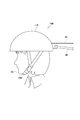
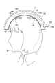
- FIG. 2 is a diagram showing a state in which the headgear 100 with electrodes is attached to a subject.
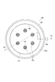
- FIG. 3 is an inside plan view of the headgear 100 with electrodes.
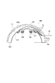
- FIG. 4 is a cross-sectional view of the headgear 100 with electrodes along the F4-F4 line of FIG.
- FIG. 5 is a single side view of the electrode unit 130.
- FIG. 6 is a single side view of the electrode unit 130.
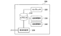
- FIG. 7 is a functional block configuration diagram of the gas supply device 200.
- FIG. 8 is a flow chart showing a procedure for using the electrode mounting system 10.
- FIG. 8 is a flow chart showing a procedure for using the electrode mounting system 10.
- FIG. 9 is a cross-sectional view of the headgear 100 with electrodes in a state where the headgear 100 with electrodes is attached to the head 60 of the subject.
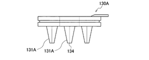
- FIG. 10 is a single side view of the electrode unit 130A according to the modified example.
- FIG. 11 is a single plan view of the electrode unit 130A according to the modified example.
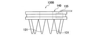
- FIG. 12 is a single side view of the electrode unit 130B according to the modified example.
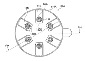
- FIG. 13 is an inside plan view of the headgear 100A with electrodes according to the modified example.
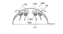
- FIG. 14 is a cross-sectional view of the headgear 100A with electrodes along the lines F14-F14 of FIG.
- FIG. 1 is an overall external view of the electrode mounting system 10 and peripheral devices. Further, FIG. 2 is a diagram showing a state in which the headgear 100 with electrodes is attached to the subject.
- the electrode mounting system 10 is composed of a headgear 100 with electrodes and a gas supply device 200.
- the headgear 100 with electrodes is attached to the subject's head 60.
- the headgear 100 with electrodes includes a helmet-shaped exterior portion 110, and the exterior portion 110 is provided with a chin strap 160 for fixing the headgear 100 with electrodes to the head 60 of the subject.
- a plurality of electrode units 130 are provided on the inner surface of the headgear 100 with electrodes.
- Headgear 100 with electrodes is typically used for subject's electroencephalogram measurement (eg, diagnosis of mood disorders, Alzheimer's disease, etc.).
- the headgear 100 with electrodes is not limited to electroencephalogram measurement, and may be used for treatment using a current supplied to the head 60 via the electrode unit 130.
- the gas supply device 200 supplies gas to the internal space 120a (not shown in FIG. 1, see FIG. 4) of the headgear 100 with electrodes. Specifically, the gas supply device 200 is connected to the headgear 100 with electrodes via an air hose 40, and supplies air to the internal space 120a of the headgear 100 with electrodes.
- the amplifier 20 is connected to the headgear 100 with electrodes via the electrode cable 50.
- the amplifier 20 performs filtering and amplification of the electrical signal detected by the electrode unit 130.
- the measurement device 30 executes measurement based on the electric signal output from the amplifier 20.
- the measuring device 30 performs electroencephalogram measurement of the subject based on the electric signal.
- the measuring device 30 may be composed of a general-purpose personal computer or a dedicated measuring device.
- FIG. 3 is an internal plan view of the headgear 100 with electrodes.
- FIG. 4 is a cross-sectional view of the headgear 100 with electrodes along the F4-F4 line of FIG.
- the headgear 100 with electrodes includes an exterior portion 110, a soft bag 120, and an electrode unit 130.
- the illustration of the chin strap 160 is omitted.
- the exterior portion 110 is in the shape of a helmet that follows the shape of the subject's head 60.
- the exterior portion 110 is preferably made of a hard and lightweight material so that the headgear 100 with electrodes can be easily attached and the inflated soft bag 120 can be brought into close contact with the head 60.
- the exterior portion 110 can typically be formed using a thermoplastic resin such as ABS resin, similar to a helmet for general use.
- At least a part of the exterior portion 110 is formed of a conductive member (for example, metal or carbon fiber). Is more preferable.
- noise (radio waves) from the outside may be prevented from being mixed in by interposing a conductive sheet-like member between the exterior portion 110 and the soft bag 120.
- the soft bag 120 is in close contact with the subject's head 60.
- the soft bag 120 is made of a synthetic resin such as cloth or vinyl that is airtight and can be freely deformed.
- the soft bag 120 forms an internal space 120a that is a closed space.
- the soft bag 120 may form an internal space 120a by being in close contact with a part of the inner side surface 111 of the exterior portion 110, or the soft bag 120 itself may have a bag shape.
- the internal space 120a may be formed by having the shape of.
- the soft bag 120 is connected to a gas supply device 200 (see FIG. 1) that supplies gas (air) to the internal space 120a via a connection port 150 to which the air hose 40 is connected.
- the internal space 120a By supplying gas (air) to the internal space 120a, the internal space 120a becomes a constant internal pressure, and the soft bag 120 expands into the shape shown in FIGS. 3 and 4.
- the electrode 131 of the electrode unit 130 is urged toward the subject's head 60.
- the soft bag 120 constitutes an urging unit.
- the electrode unit 130 has a plurality of convex electrodes 131.
- the headgear 100 with electrodes is provided with a plurality (six) electrode units 130.
- the electrode unit 130 is provided on the soft bag 120 so that a part of the electrode unit 130 is exposed from the inner surface 121 (head contact surface) of the soft bag 120.
- the soft bag 120 urges the electrode unit 130 toward the convex direction of the electrode 131.
- Wiring 51 separated from the electrode cable 50 is connected to the electrode unit 130, respectively.
- FIG. 5 is a side view of the electrode unit 130 as a single unit.
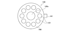
- FIG. 6 is a single plan view of the electrode unit 130 on the electrode 131 side.
- the electrode unit 130 has an electrode 131 and a base 140.
- the electrode unit 130 is formed of conductive rubber and has a certain elasticity.
- the electrode 131 is convex and includes the tip 132. Further, the base end portion 133 of the electrode 131 is connected to the surface of the base portion 140.
- the tip 132 is the part that comes into contact with the subject's head 60, specifically the subject's scalp.
- the tip portion 132 has a tapered shape.
- the electrode unit 130 has a plurality of (10) electrodes 131.
- the electrode 131 projects from the surface of the base 140.
- the base 140 is disk-shaped.
- a wiring connection portion 141 is provided on the peripheral portion of the base portion 140.
- a wiring 51 (see FIG. 4) extending from the electrode cable 50 is connected to the wiring connection portion 141.
- a recess 142 is formed on the outer peripheral portion of the base 140.
- the soft bag 120 is formed with a mounting hole (not shown) for the electrode unit, and the recess 142 is fitted with an open end portion of the soft bag 120 forming the mounting hole.
- a ventilation hole 140a is formed in the base 140.
- the ventilation hole 140a communicates with the internal space 120a of the soft bag 120 and opens in the convex direction of the electrode 131.
- the gas (air) supplied from the gas supply device 200 to the internal space 120a is discharged from the ventilation holes 140a in the convex direction of the electrode 131. That is, the tip 132 of the electrode 131 and the ventilation hole 140a are exposed from the inner surface 111 (head contact surface) of the soft bag.
- FIG. 7 is a functional block configuration diagram of the gas supply device 200.
- the gas supply device 200 includes an air tank 210, a compressor 220, a temperature control unit 230, a humidity control unit 240, and a gas supply unit 250.
- the air tank 210 stores gas, specifically air.
- the compressor 220 sends compressed air into the air tank 210.
- the temperature adjusting unit 230 adjusts the temperature of the air stored in the air tank 210. Specifically, the temperature adjusting unit 230 measures the temperature of the air stored in the air tank 210 and heats the air stored in the air tank 210 to a set temperature.
- the set temperature is preferably a temperature higher than the temperature of the space in which the headgear with electrodes is provided. Further, it is more preferable that the set temperature is a temperature slightly higher than the body temperature of the subject, that is, a human. However, in this case, it is appropriate to set the temperature to 41 degrees or less.
- the humidity adjustment unit 240 adjusts the temperature of the air stored in the air tank 210. Specifically, the humidity adjusting unit 240 measures the humidity of the air stored in the air tank 210, and humidifies the air stored in the air tank 210 so as to have a set humidity.
- the set humidity is set as much as possible without dew condensation when the air stored in the air tank 210 is supplied to the subject's head 60 through the internal space 120a of the soft bag 120 and the ventilation hole 140a of the electrode unit 130.
- High humidity is preferred.
- such humidity is 80-90%.
- mist-like air can be discharged from the ventilation hole 140a.
- the gas supply unit 250 supplies the air stored in the air tank 210 to the headgear 100 with electrodes.
- the gas supply unit 250 supplies the air stored in the air tank 210 to the internal space 120a of the soft bag 120 based on the supply instruction input to the gas supply device 200.
- the supply instruction to the gas supply device 200 may be input via an operation unit (not shown) provided on the front surface of the gas supply device 200, or from an external device (not shown) by wire or wireless communication or the like. May be entered.
- the gas supply unit 250 supplies air (temperature control gas) adjusted to the set temperature by the temperature adjustment unit 230 and adjusted to the set humidity by the humidity adjustment unit 240 to the internal space 120a of the soft bag 120.
- the supplied air temperature control gas
- the supplied air is set to a temperature higher than the temperature of the space in which the headgear with electrodes is provided, preferably a temperature slightly higher than the human body temperature, and has a predetermined humidity or higher. It is a mist of.
- the gas supply unit 250 may intermittently supply air (temperature-controlled gas) adjusted to the set temperature and the set humidity to the internal space 120a of the soft bag 120.
- the gas supply unit 250 repeatedly supplies and stops air according to a predetermined frequency (period). Such air may be referred to as wave air.
- the frequency is preferably about 0.5 Hz to 10 Hz.
- FIG. 8 is a flow chart showing a procedure for using the electrode mounting system 10.
- the flow chart shown in FIG. 8 shows an example of measuring an electroencephalogram of a subject.
- the operator of the electrode mounting system 10 wears the electrode-equipped headgear 100 on the subject's head 60 (S10). Specifically, the operator attaches the headgear 100 with electrodes in a state where the soft bag 120 is deflated to the head 60 of the subject, and locks the chin strap 160 to the chin of the subject.
- the operator connects the air hose 40 to the connection port 150 of the headgear 100 with electrodes (S20).
- the other end of the air hose 40 is connected to the gas supply device 200.
- the electrode cable 50 is previously connected to the measuring device 30 via the amplifier 20.
- the operator supplies air from the gas supply device 200 to the soft bag 120 of the headgear 100 with electrodes (S30).
- the operator operates the gas supply device 200 to supply air to the internal space 120a of the soft bag 120.
- FIG. 9 is a cross-sectional view of the headgear 100 with electrodes in a state where the headgear 100 with electrodes is attached to the head 60 of the subject. As shown in FIG. 9, the air flow F flowing in from the hole 150a of the connection port 150 inflates the soft bag 120 and expands the internal space 120a.
- the air flow F is ejected from the ventilation holes 140a formed in the electrode unit 130 to the outside of the soft bag 120. Specifically, the air flow F is ejected from the ventilation hole 140a toward the subject's head 60.
- the air supplied from the gas supply device 200 to the internal space 120a of the soft bag 120 is adjusted to the set temperature and the set humidity. Further, air may be intermittently supplied to the internal space 120a of the soft bag 120 according to a predetermined frequency.
- the air flow F When such an air flow F vigorously blows out from the vent 140a to the outside of the soft bag 120, the air flow F forms a space in which the subject's hair 61 is scraped off, so that the electrode 131 of the electrode unit 130 is the subject. Easy to reach the scalp.
- the operator confirms whether or not the electrode 131 of the electrode unit 130 has come into contact with the subject's scalp (S40). Specifically, the operator confirms whether or not the tip 132 of the electrode 131 has come into contact with the scalp of the subject.
- the operator can confirm, for example, that the tip 132 of the electrode 131 has come into contact with the scalp of the subject by the value of the electric signal detected by the electrode unit 130.
- the pressure of air supplied to the internal space 120a of the soft bag 120 may be slightly lower than that at the stage of mounting the electrode 131 of S30. That is, it is sufficient that the air is continuously supplied to the internal space 120a by a pressure sufficient to maintain the swelling of the soft bag 120.
- the electrode unit 130 of the headgear 100 with electrodes is formed with ventilation holes 140a that open in the convex direction of the electrodes 131. Further, the headgear 100 with electrodes includes a soft bag 120 (biasing unit) that biases the electrode unit 130 toward the convex direction of the electrodes 131.
- the electrode unit 130 is urged toward the subject's head 60.
- the air supplied from the gas supply device 200 is discharged through the ventilation hole 140a. Specifically, since the air is vigorously ejected, the subject's hair 61 is scraped off, and the electrode 131 is not disturbed by the hair 61. Almost reach the subject's scalp.
- the tip 132 of the electrode 131 can be more reliably and easily brought into contact with the scalp of the subject while avoiding the discomfort and pain of the subject.
- the electrical resistance of the measurement target (head 60) can be suppressed.
- a method of attaching an electrode to the head 60 of a subject while using a conductive paste or gel for the purpose of suppressing electrical resistance is known.
- a conductive paste or gel for the purpose of suppressing electrical resistance
- the electrode 131 may be urged with a force that causes light contact with the scalp of the subject. As a result, the electrode 131 causes less irritation to the scalp.
- the soft bag 120 that is in close contact with the subject's head 60 is used, and the air from the gas supply device 200 is supplied to the internal space 120a.
- the soft bag 120 easily follows the shape of the head 60, and the position of the electrode unit 130 easily fits the shape of the head 60. That is, the electrode 131 can more reliably come into contact with the subject's scalp. In addition, the softbag 120 can easily follow the shape of the head 60 and thus accommodate a wide range of head 60 sizes.
- the tip portion 132 of the electrode 131 and the ventilation hole 140a are exposed from the inner side surface 121 (head contact surface) of the soft bag 120. Therefore, in the inflated state of the soft bag 120, the subject's hair 61 can be more reliably scraped off, and the tip 132 of the electrode 131 can be brought into contact with the subject's scalp.
- a helmet-shaped exterior portion 110 that follows the shape of the subject's head 60 is provided on the outside of the soft bag 120, and the exterior portion 110 is formed of a conductive member (metal or the like). To. Therefore, it is possible to effectively prevent noise (radio waves) from being mixed into the electric signal detected by the electrode unit 130.
- FIG. 10 is a single side view of the electrode unit 130A according to the modified example.
- FIG. 11 is a single plan view of the electrode unit 130A according to the modified example.
- the electrode unit 130A has a plurality of convex electrodes 131A. Specifically, the electrode unit 130A has three electrodes 131A. The number of electrodes 131A included in the electrode unit 130A is preferably 3 or less.
- the electrode 131A has a triangular pyramid shape as compared with the electrode 131 of the electrode unit 130 (see FIGS. 5 and 6). That is, the cross section of the electrode 131A along the direction orthogonal to the convex direction is a triangle.
- the tip portion 134 of the electrode 131A is not tapered like the tip portion 132 of the electrode 131, but has a flat flat shape.
- the electrode unit 130A is also formed with ventilation holes 140a having the same shape as the electrode unit 130.
- the corners of the electrode 131A having a triangular cross section are more likely to come into contact with the scalp of the subject more reliably, and the required number of electrodes 131A can be suppressed.
- FIG. 12 is a single side view of the electrode unit 130B according to the modified example. As shown in FIG. 12, the electrode unit 130B has a vibrator 135.
- the vibrator 135 is incorporated inside the base 140 and vibrates the electrode unit 130B.
- the same method as the vibrator incorporated in a smartphone or the like for example, a linear resonance actuator, an eccentric rotation motor
- a linear resonance actuator for example, a linear resonance actuator, an eccentric rotation motor
- the electrode 131 can be more reliably brought into contact with the scalp of the subject of the electrode unit 130B.
- FIG. 13 is an inside plan view of the headgear 100A with electrodes according to the modified example.
- FIG. 14 is a cross-sectional view of the headgear 100A with electrodes along the lines F14-F14 of FIG.
- the electrode-equipped headgear 100A does not have the softbag 120 like the electrode-equipped headgear 100. Instead, the exterior portion 110A is formed with a plurality of urging plate-like portions 115.
- One electrode unit 130C is attached to each of the urging plate-shaped portions 115.
- the urging plate-shaped portion 115 urges the electrode unit 130C toward the convex direction of the electrode 131.
- the exterior portion 110A constitutes an urging unit.
- An air hose 152 to which air from the gas supply device 200 is supplied is connected to the electrode unit 130C.
- the electrode unit 130C is formed with a ventilation hole 140b that communicates with the air hose 152.
- the air supplied from the gas supply device 200 is blown out to the outside through the air hose 152 and the ventilation hole 140b.
- the gas supplied from the gas supply device 200 has been described as an example of air, but the gas is not necessarily limited to air.
- the gas supplied from the gas supply device 200 is adjusted to the set temperature and the set humidity, but the gas does not necessarily have to be adjusted to the set temperature, and the set humidity does not have to be adjusted. It does not have to be adjusted to.
- Electrode mounting system 20
- Amplifier 30 Measuring device 40
- Air hose 50
- Electrode cable 51
- Wiring 60
- Head 61 Hair
- 100 100A Head gear with electrodes
- 110, 110A Exterior 111
- Inner side 115
- Bias plate 120
- Softbag 121
- Inner side 120a
- Internal space 130, 130A, 130B, 130C
- Electrode 132 Tip 133
- Base end 134
- Wiring connection 142 Recess 150 Connection port 150a Hole 152
- Air hose 160 Jaw cord 200
- Gas supply device 210
- Air tank 220 Compressor
- Temperature adjustment unit 240
- Humidity adjustment unit 250
- Gas supply unit F Air flow
Landscapes
- Life Sciences & Earth Sciences (AREA)
- Health & Medical Sciences (AREA)
- Medical Informatics (AREA)
- Biophysics (AREA)
- Pathology (AREA)
- Engineering & Computer Science (AREA)
- Biomedical Technology (AREA)
- Heart & Thoracic Surgery (AREA)
- Physics & Mathematics (AREA)
- Molecular Biology (AREA)
- Surgery (AREA)
- Animal Behavior & Ethology (AREA)
- General Health & Medical Sciences (AREA)
- Public Health (AREA)
- Veterinary Medicine (AREA)
- Measurement And Recording Of Electrical Phenomena And Electrical Characteristics Of The Living Body (AREA)
Abstract
電極付きヘッドギア(100)の電極ユニット(130)は、凸状の電極(131)を複数有する。電極ユニット(130)には、電極(131)の凸方向に向けて開口する通気孔が形成される。電極付きヘッドギア(100)は、電極ユニット(130)を電極(131)の凸方向に向けて付勢するソフトバッグ(120)を備える。
Description
本発明は、脳波測定などに用いられる電極付きヘッドギア、気体供給装置及び電極装着システムに関する。
従来、脳波測定などでは、被験者の頭皮と接触する電極を有する電極付きヘッドギアが広く用いられている(特許文献1参照)。
このような電極付きヘッドギアでは、電極の先端部を頭皮と確実に接触させ、測定対象(頭部)の電気抵抗を抑える(例えば20kΩ以下)ことが重要である。電極数を減らし、電極の先端部を鋭利にすれば、当該電気抵抗を比較的容易に抑制できるが、被験者の不快感や痛みを伴うため、好ましくない。
そこで、特許文献1に記載されている電極付きヘッドギアでは、円筒状のリセプタクル部を介して被験者の頭髪が視認できる電極ユニットが採用されている。このため、電極付きヘッドギアを被験者に装着する装着者は、リセプタクル部内の頭髪を掻き分けつつ、電極が接続された円形のゲル状シートをリセプタクル部に挿入できる。
上述した従来の電極付きヘッドギアによれば、電極の先端部を頭皮と確実に接触させ、測定対象(頭部)の電気抵抗を抑制し得るが、頭髪を掻き分ける手間などがあり、改善の余地がある。
そこで、本発明は、このような状況に鑑みてなされたものであり、被験者の不快感や痛みを回避しつつ、より確実かつ容易に被験者の頭皮に電極の先端部を接触させることができる電極付きヘッドギア、気体供給装置及び電極装着システムの提供を目的とする。
本発明の一態様は、電極ユニット(例えば、電極ユニット130)を備える電極付きヘッドギア(電極付きヘッドギア100)であって、前記電極ユニットは、凸状の電極(電極131)を複数有し、前記電極ユニットには、前記電極の凸方向に向けて開口する通気孔(通気孔140a)が形成され、前記電極ユニットを前記電極の凸方向に向けて付勢する付勢ユニット(ソフトバッグ120)を備える。
本発明の一態様は、気体供給装置(気体供給装置200)であって、電極付きヘッドギア(例えば、電極付きヘッドギア100)が備えられている空間の温度より高い温度に調節された温調気体を前記電極付きヘッドギアに供給する気体供給部(気体供給部250)を備える。
本発明の一態様は、電極ユニットを備える電極付きヘッドギアと、前記電極付きヘッドギアに気体を供給する気体供給装置とを含む電極装着システム(電極装着システム10)であって、電極ユニットは、凸状の電極を複数有し、前記電極ユニットには、前記電極の凸方向に向けて開口する通気孔が形成され、電極付きヘッドギアは、前記電極ユニットを前記電極の凸方向に向けて付勢する付勢ユニットを備え、前記気体供給装置は、前記電極付きヘッドギアが備えられている空間の温度より高い温度に調節された温調気体を前記電極付きヘッドギア内の内部空間に供給する気体供給部を備える。
以下、実施形態を図面に基づいて説明する。なお、同一の機能や構成には、同一または類似の符号を付して、その説明を適宜省略する。
(1)電極装着システムの全体概略構成
図1は、電極装着システム10及び周辺装置の全体外観図である。また、図2は、電極付きヘッドギア100の被験者への装着状態を示す図である。
図1は、電極装着システム10及び周辺装置の全体外観図である。また、図2は、電極付きヘッドギア100の被験者への装着状態を示す図である。
図1及び図2に示すように、電極装着システム10は、電極付きヘッドギア100及び気体供給装置200によって構成される。
電極付きヘッドギア100は、被験者の頭部60に装着される。電極付きヘッドギア100は、ヘルメット状の外装部110を備え、外装部110には、被験者の頭部60に電極付きヘッドギア100を固定するために、顎紐160が設けられる。
電極付きヘッドギア100の内側面には、複数の電極ユニット130(図1において不図示、図5,6参照)が設けられる。
電極付きヘッドギア100は、典型的には、被験者の脳波測定(例えば、気分障害やアルツハイマーなどの診断)に用いられる。但し、電極付きヘッドギア100は、脳波測定に限定されず、電極ユニット130を介して頭部60に供給される電流を利用した治療などに用いられてもよい。
気体供給装置200は、電極付きヘッドギア100の内部空間120a(図1において不図示、図4参照)に気体を供給する。具体的には、気体供給装置200は、エアホース40を介して電極付きヘッドギア100と接続され、電極付きヘッドギア100の内部空間120aに空気を供給する。
また、電極付きヘッドギア100には、電極ケーブル50を介して増幅器20が接続される。増幅器20は、電極ユニット130が検出した電気信号のフィルタリング及び増幅を実行する。
測定デバイス30は、増幅器20から出力された電気信号に基づく測定を実行する。本実施形態では、測定デバイス30は、当該電気信号に基づいて被験者の脳波測定を実行する。測定デバイス30は、一般的な汎用のパーソナルコンピュータによって構成されてもよいし、専用の測定装置でもよい。
(2)電極付きヘッドギア100の構成
図3は、電極付きヘッドギア100の内側平面図である。図4は、図3のF4-F4線に沿った電極付きヘッドギア100の断面図である。
図3は、電極付きヘッドギア100の内側平面図である。図4は、図3のF4-F4線に沿った電極付きヘッドギア100の断面図である。
図3及び図4に示すように、電極付きヘッドギア100は、外装部110、ソフトバッグ120及び電極ユニット130を備える。なお、図3及び図4では、顎紐160(図2参照)の図示は省略されている。
外装部110は、被験者の頭部60の形状に沿ったヘルメット状である。外装部110は、電極付きヘッドギア100が容易に装着でき、かつ膨らんだソフトバッグ120が頭部60に密着できるように、硬質かつ軽量な材料で形成されることが好ましい。
外装部110は、典型的には、一般的な用途のヘルメットと同様に、ABS樹脂などの熱可塑性樹脂を用いて形成できる。
但し、電極ユニット130が検出する電気信号への外部からのノイズ(電波)混入防止を考慮すると、少なくとも外装部110の一部は、導電性を有する部材(例えば、金属、炭素繊維)によって形成されることがより好ましい。或いは、外装部110とソフトバッグ120との間に導電性を有するシート状の部材を介在させることによって、外部からのノイズ(電波)混入を防止してもよい。
ソフトバッグ120は、被験者の頭部60に密着する。具体的には、ソフトバッグ120は、気密性を有し、自由に変形できる布またはビニールなどの合成樹脂によって形成される。
ソフトバッグ120は、閉空間となる内部空間120aを形成する。具体的には、図4に示すように、ソフトバッグ120は、外装部110の内側面111の一部と密着することによって内部空間120aを形成してもよいし、ソフトバッグ120自体が袋状の形状を有することによって、内部空間120aを形成してもよい。
ソフトバッグ120は、エアホース40が接続される接続口150を介して気体(空気)を内部空間120aに供給する気体供給装置200(図1参照)と接続される。
気体(空気)が内部空間120aに供給されることによって、内部空間120aが一定の内圧となり、ソフトバッグ120は、図3及び図4に示すような形状に膨らむ。
ソフトバッグ120が膨らむと、電極ユニット130の電極131を被験者の頭部60に向けて付勢する。本実施形態において、ソフトバッグ120は、付勢ユニットを構成する。
一方、内部空間120aへの気体の供給が遮断されると、内部空間120aの内圧が低下し、ソフトバッグ120は萎んだ状態となる。
電極ユニット130は、複数の凸状の電極131を有する。本実施形態では、電極付きヘッドギア100には、複数(6個)の電極ユニット130が設けられる。
電極ユニット130は、ソフトバッグ120の内側面121(頭部接触面)から一部が露出するようにソフトバッグ120に設けられる。ソフトバッグ120は、電極ユニット130を電極131の凸方向に向けて付勢する。
電極ユニット130には、電極ケーブル50から分離した配線51がそれぞれ接続される。
(3)電極ユニット130の形状
図5は、電極ユニット130の単体側面図である。図6は、電極131側の電極ユニット130の単体平面図である。
図5は、電極ユニット130の単体側面図である。図6は、電極131側の電極ユニット130の単体平面図である。
図5及び図6に示すように、電極ユニット130は、電極131及び基部140を有する。本実施形態では、電極ユニット130は、導電性のゴムによって形成され、一定の弾力性を有する。
電極131は、凸状であり、先端部132を含む。また、電極131の基端部133は、基部140の表面に連なる。
先端部132は、被験者の頭部60、具体的には、被験者の頭皮と接触する部分である。本実施形態では、先端部132は、テーパー状である。
本実施形態では、電極ユニット130は、複数(10本)の電極131を有する。電極131は、基部140の表面から突出する。
基部140は、円盤状である。基部140の周縁部分は、配線接続部141が設けられる。配線接続部141には、電極ケーブル50から延びる配線51(図4参照)が接続される。
基部140の外周部分には、凹部142が形成される。ソフトバッグ120には、電極ユニットの取付孔(不図示)が形成されており、凹部142には、ソフトバッグ120の当該取付孔を形成する開口端部分が嵌め込まれる。
また、基部140には、通気孔140aが形成されている。通気孔140aは、ソフトバッグ120の内部空間120aと連通し、電極131の凸方向に向けて開口する。
気体供給装置200から内部空間120aに供給された気体(空気)は、通気孔140aから電極131の凸方向に向けて排出される。つまり、電極131の先端部132及び通気孔140aは、ソフトバッグの内側面111(頭部接触面)から露出する。
(3)気体供給装置の構成
図7は、気体供給装置200の機能ブロック構成図である。図7に示すように、気体供給装置200は、エアタンク210、コンプレッサ220、温度調整部230、湿度調整部240及び気体供給部250を備える。
図7は、気体供給装置200の機能ブロック構成図である。図7に示すように、気体供給装置200は、エアタンク210、コンプレッサ220、温度調整部230、湿度調整部240及び気体供給部250を備える。
エアタンク210は、気体、具体的には空気を蓄える。コンプレッサ220は、エアタンク210に圧縮された空気を送り込む。
温度調整部230は、エアタンク210に蓄えられている空気の温度を調整する。具体的には、温度調整部230は、エアタンク210に蓄えられている空気の温度を測定し、エアタンク210に蓄えられている空気を設定温度になるように加温する。
設定温度は、電極付きヘッドギアが備えられている空間の温度より高い温度であることが好ましい。また、設定温度は、被験者、つまり、ヒトの体温よりも少し高い温度であることがより好ましい。但し、この場合、41度以下とすることが妥当である。
湿度調整部240は、エアタンク210に蓄えられている空気の温度を調整する。具体的には、湿度調整部240は、エアタンク210に蓄えられている空気の湿度を測定し、エアタンク210に蓄えられている空気を設定湿度になるように加湿する。
設定湿度は、エアタンク210に蓄えられている空気がソフトバッグ120の内部空間120a及び電極ユニット130の通気孔140aを介して被験者の頭部60に供給された際に、結露せずに可能な限り高い湿度とすることが好ましい。一般的には、このような湿度(相対湿度)は、80~90%である。これにより、霧状の空気を通気孔140aから排出できる。
気体供給部250は、エアタンク210に蓄えられている空気を電極付きヘッドギア100に供給する。
具体的には、気体供給部250は、気体供給装置200に入力された供給指示に基づいて、エアタンク210に蓄えられている空気をソフトバッグ120の内部空間120aに供給する。気体供給装置200に対する供給指示は、気体供給装置200の前面に設けられた操作部(不図示)を介して入力されてもよいし、有線または無線通信などによって、外部の装置(不図示)から入力されてもよい。
本実施形態では、気体供給部250は、温度調整部230によって設定温度に調節され、かつ湿度調整部240によって設定湿度に調整された空気(温調気体)をソフトバッグ120の内部空間120aに供給する。供給される空気(温調気体)は、上述したように、電極付きヘッドギアが備えられている空間の温度より高い温度、好ましくはヒトの体温よりも少し高い温度に設定されるとともに、所定湿度以上の霧状である。
また、気体供給部250は、設定温度及び設定湿度に調整された空気(温調気体)をソフトバッグ120の内部空間120aに断続的に供給してもよい。
具体的には、気体供給部250は、所定の周波数(周期)に従って、空気の供給と停止を繰り返す。このような空気は、波動空気と呼ばれてもよい。当該周波数は、0.5Hz~10Hz程度であることが好ましい。
(4)電極装着システムの使用手順
図8は、電極装着システム10の使用手順を示すフロー図である。図8に示すフロー図は、被験者の脳波を測定する例を示す。
図8は、電極装着システム10の使用手順を示すフロー図である。図8に示すフロー図は、被験者の脳波を測定する例を示す。
図8に示すように、電極装着システム10の操作者(医療従事者など)は、電極付きヘッドギア100を被験者の頭部60に装着する(S10)。具体的には、操作者は、ソフトバッグ120が萎んだ状態の電極付きヘッドギア100を被験者の頭部60に装着し、顎紐160を被験者の顎に係止する。
次いで、操作者は、エアホース40を電極付きヘッドギア100の接続口150に接続する(S20)。エアホース40の他端は、気体供給装置200に接続されている。なお、ここでは、電極ケーブル50は、予め増幅器20を介して測定デバイス30と接続されているものとする。
操作者は、気体供給装置200から電極付きヘッドギア100のソフトバッグ120に空気を供給する(S30)。
具体的には、操作者は、気体供給装置200を操作し、ソフトバッグ120の内部空間120aに空気を供給する。
ソフトバッグ120の内部空間120aに空気を供給する初期段階では、圧力を高めた空気を供給し、ソフトバッグ120を確実に膨らませ、被験者の頭部60に密着させることが好ましい。
ソフトバッグ120が規定サイズまで膨らみきると、電極ユニット130に形成された通気孔140aから空気が排出される。
図9は、電極付きヘッドギア100が被験者の頭部60に装着された状態における電極付きヘッドギア100の断面図である。図9に示すように、接続口150の孔部150aから流入した空気流Fは、ソフトバッグ120を膨らませ、内部空間120aを拡張する。
また、ソフトバッグ120が規定サイズまで膨らみきると、空気流Fは、電極ユニット130に形成された通気孔140aからソフトバッグ120の外部に噴き出す。具体的には、空気流Fは、通気孔140aから被験者の頭部60に向けて噴き出す。
なお、上述したように、気体供給装置200からソフトバッグ120の内部空間120aに供給される空気は、設定温度及び設定湿度に調整されている。また、ソフトバッグ120の内部空間120aには、所定の周波数に従って断続的に空気が供給されてもよい。
このような空気流Fが通気孔140aからソフトバッグ120の外部に勢いよく噴き出すと、空気流Fによって被験者の頭髪61が掻き分けられた空間が形成されるため、電極ユニット130の電極131が被験者の頭皮まで容易に到達する。
次いで、操作者は、電極ユニット130の電極131が被験者の頭皮に接触したか否かを確認する(S40)。具体的には、操作者は、電極131の先端部132が被験者の頭皮に接触したか否かを確認する。
なお、操作者は、例えば、電極ユニット130が検出した電気信号の値によって電極131の先端部132が被験者の頭皮に接触したことを確認し得る。
操作者は、電極ユニット130の電極131が被験者の頭皮に接触したことを確認すると、被験者の脳波測定を開始する(S50)。
脳波測定の段階では、ソフトバッグ120の内部空間120aに供給される空気の圧力は、S30の電極131の装着段階よりも少し低下させてよい。つまり、ソフトバッグ120の膨らみが維持される程度の圧力によって内部空間120aに空気が供給され続ければよい。
(5)作用・効果
上述した実施形態によれば、以下の作用効果が得られる。具体的には、電極付きヘッドギア100の電極ユニット130には、電極131の凸方向に向けて開口する通気孔140aが形成される。また、電極付きヘッドギア100は、電極ユニット130を電極131の凸方向に向けて付勢するソフトバッグ120(付勢ユニット)を備える。
上述した実施形態によれば、以下の作用効果が得られる。具体的には、電極付きヘッドギア100の電極ユニット130には、電極131の凸方向に向けて開口する通気孔140aが形成される。また、電極付きヘッドギア100は、電極ユニット130を電極131の凸方向に向けて付勢するソフトバッグ120(付勢ユニット)を備える。
このため、膨らんだソフトバッグ120が被験者の頭部60に密着することによって、電極ユニット130が被験者の頭部60に向けて付勢される。また、通気孔140aを介して気体供給装置200から供給された空気が排出される、具体的には、勢いよく噴き出すため、被験者の頭髪61が掻き分けられ、頭髪61に邪魔されずに電極131が被験者の頭皮まで容易に到達する。
これにより、被験者の不快感や痛みを回避しつつ、より確実かつ容易に被験者の頭皮に電極131の先端部132を接触させることができる。この結果、測定対象(頭部60)の電気抵抗が抑制し得る。
なお、電気抵抗の抑制などを目的として、導電性のペーストまたはジェルを用いつつ、被験者の頭部60に電極を装着する方法が知られている。しかしながら、装着には専門的な知識が必要となること、測定後に洗髪が必要であり、被験者に負担が掛かること、及び電極による頭皮への刺激が強いことが課題である。
電極付きヘッドギア100の装着では、ペーストやジェルは用いられない。また、空気流Fによって頭髪61が掻き分けられるため、電極131は、被験者の頭皮に軽く接触する程度の力で付勢されていればよい。これにより、電極131による頭皮への刺激も少ない。
本実施形態では、被験者の頭部60に密着するソフトバッグ120が用いられ、内部空間120aには、気体供給装置200からの空気が供給される。
このため、ソフトバッグ120は、頭部60の形状に追従し易く、電極ユニット130の位置が頭部60の形状にフィットし易い。つまり、さらに確実に電極131が被験者の頭皮と接触し得る。さらに、ソフトバッグ120は、頭部60の形状に追従し易いため、広範な頭部60のサイズに対応し得る。
本実施形態では、電極131の先端部132及び通気孔140aは、ソフトバッグ120の内側面121(頭部接触面)から露出する。このため、ソフトバッグ120が膨らんだ状態において、より確実に被験者の頭髪61を掻き分け、電極131の先端部132を被験者の頭皮に接触させることができる。
本実施形態では、ソフトバッグ120の外側には、被験者の頭部60の形状に沿ったヘルメット状の外装部110が設けられ、外装部110は、導電性を有する部材(金属など)によって形成される。このため、電極ユニット130が検出する電気信号への外部からのノイズ(電波)混入を効果的に防止し得る。
(6)その他の実施形態
以上、実施例に沿って本発明の内容を説明したが、本発明はこれらの記載に限定されるものではなく、種々の変形及び改良が可能であることは、当業者には自明である。
以上、実施例に沿って本発明の内容を説明したが、本発明はこれらの記載に限定されるものではなく、種々の変形及び改良が可能であることは、当業者には自明である。
例えば、上述した電極ユニット130は、次のように変更してもよい。図10は、変更例に係る電極ユニット130Aの単体側面図である。図11は、変更例に係る電極ユニット130Aの単体平面図である。
図10及び図11に示すように、電極ユニット130Aは、複数の凸状の電極131Aを有する。具体的には、電極ユニット130Aは、3本の電極131Aを有する。なお、電極ユニット130Aが有する電極131Aの数は、3本以下であることが好ましい。
電極131Aは、電極ユニット130の電極131(図5,6参照)と比較すると、三角錐状である。つまり、電極131Aの凸方向に直交する方向に沿った断面は、三角形である。
また、電極131Aの先端部134は、電極131の先端部132のようにテーパー状ではなく、フラットな平面状ある。なお、電極ユニット130Aにも、電極ユニット130と同形状の通気孔140aが形成される。
電極ユニット130Aによれば、断面が三角形である電極131Aの角部が、被験者の頭皮とより確実に接触し易く、必要な電極131Aの数も抑制し得る。
図12は、変更例に係る電極ユニット130Bの単体側面図である。図12に示すように、電極ユニット130Bは、バイブレータ135を有する。
バイブレータ135は、基部140内部に組み込まれており、電極ユニット130Bを振動させる。バイブレータ135としては、スマートフォンなどに組み込まれているバイブレータと同様の方式(例えば、リニア共振アクチュエータ、偏心回転モータ)を適用し得る。
これにより、電極ユニット130Bのさらに確実に被験者の頭皮に電極131を接触させることができる。
図13は、変更例に係る電極付きヘッドギア100Aの内側平面図である。図14は、図13のF14-F14線に沿った電極付きヘッドギア100Aの断面図である。
図13及び図14に示すように、電極付きヘッドギア100Aは、電極付きヘッドギア100のようにソフトバッグ120を備えていない。代わりに、外装部110Aには、複数の付勢板状部115が形成される。
付勢板状部115のそれぞれには、1個の電極ユニット130Cが取り付けられている。付勢板状部115は、電極ユニット130Cを電極131の凸方向に向けて付勢する。本変更例において、外装部110Aは、付勢ユニットを構成する。
電極ユニット130Cには、気体供給装置200からの空気が供給されるエアホース152が接続される。
電極ユニット130Cには、エアホース152と連通する通気孔140bが形成される。気体供給装置200から供給される空気は、エアホース152及び通気孔140bを介して外部に噴き出す。
また、上述した実施形態では、気体供給装置200から供給される気体は、空気であることを例として説明したが、当該気体は、必ずしも空気に限定されない。
さらに、上述した実施形態では、気体供給装置200から供給される気体は、設定温度及び設定湿度に調整されていたが、当該気体は、必ずしも設定温度に調整されていなくてもよいし、設定湿度に調整されていなくても構わない。
上記のように、本発明の実施形態を記載したが、この開示の一部をなす論述及び図面はこの発明を限定するものであると理解すべきではない。この開示から当業者には様々な代替実施の形態、実施例及び運用技術が明らかとなろう。
10 電極装着システム
20 増幅器
30 測定デバイス
40 エアホース
50 電極ケーブル
51 配線
60 頭部
61 頭髪
100, 100A 電極付きヘッドギア
110, 110A 外装部
111 内側面
115 付勢板状部
120 ソフトバッグ
121 内側面
120a 内部空間
130, 130A, 130B, 130C 電極ユニット
131, 131A 電極
132 先端部
133 基端部
134 先端部
135 バイブレータ
140 基部
140a, 140b 通気孔
141 配線接続部
142 凹部
150 接続口
150a 孔部
152 エアホース
160 顎紐
200 気体供給装置
210 エアタンク
220 コンプレッサ
230 温度調整部
240 湿度調整部
250 気体供給部
F 空気流
20 増幅器
30 測定デバイス
40 エアホース
50 電極ケーブル
51 配線
60 頭部
61 頭髪
100, 100A 電極付きヘッドギア
110, 110A 外装部
111 内側面
115 付勢板状部
120 ソフトバッグ
121 内側面
120a 内部空間
130, 130A, 130B, 130C 電極ユニット
131, 131A 電極
132 先端部
133 基端部
134 先端部
135 バイブレータ
140 基部
140a, 140b 通気孔
141 配線接続部
142 凹部
150 接続口
150a 孔部
152 エアホース
160 顎紐
200 気体供給装置
210 エアタンク
220 コンプレッサ
230 温度調整部
240 湿度調整部
250 気体供給部
F 空気流
Claims (9)
- 電極ユニットを備える電極付きヘッドギアであって、
前記電極ユニットは、凸状の電極を複数有し、
前記電極ユニットには、前記電極の凸方向に向けて開口する通気孔が形成され、
前記電極ユニットを前記電極の凸方向に向けて付勢する付勢ユニットを備える電極付きヘッドギア。 - 前記付勢ユニットは、被験者の頭部に密着するソフトバッグによって構成され、
前記ソフトバッグは、前記ソフトバッグの内部空間に気体を供給する気体供給装置と接続され、
前記通気孔は、前記内部空間に連通し、
少なくとも前記電極の先端部及び前記通気孔は、前記ソフトバッグの頭部接触面から露出する請求項1に記載の電極付きヘッドギア。 - 前記付勢ユニットの外側には、前記頭部の形状に沿ったヘルメット状の外装部が設けられ、
前記外装部の少なくとも一部は、導電性を有する部材によって形成される請求項2に記載の電極付きヘッドギア。 - 前記電極ユニットが有する前記電極の数は、3本以下である請求項1乃至3の何れか一項に記載の電極付きヘッドギア。
- 前記電極ユニットは、前記電極ユニットを振動させるバイブレータを有する請求項1乃至4の何れか一項に記載の電極付きヘッドギア。
- 電極付きヘッドギアが備えられている空間の温度より高い温度に調節された温調気体を前記電極付きヘッドギア内の内部空間に供給する気体供給部を備える気体供給装置。
- 前記気体供給部は、前記温調気体を前記内部空間に断続的に供給する請求項6に記載の気体供給装置。
- 前記気体供給部は、所定湿度以上の霧状の前記温調気体を供給する請求項6または7に記載の気体供給装置。
- 電極ユニットを備える電極付きヘッドギアと、前記電極付きヘッドギアに気体を供給する気体供給装置とを含む電極装着システムであって、
電極ユニットは、凸状の電極を複数有し、
前記電極ユニットには、前記電極の凸方向に向けて開口する通気孔が形成され、
電極付きヘッドギアは、前記電極ユニットを前記電極の凸方向に向けて付勢する付勢ユニットを備え、
前記気体供給装置は、前記電極付きヘッドギアが備えられている空間の温度より高い温度に調節された温調気体を前記電極付きヘッドギア内の内部空間に供給する気体供給部を備える電極装着システム。
Priority Applications (1)
| Application Number | Priority Date | Filing Date | Title |
|---|---|---|---|
| JP2021514186A JP7586073B2 (ja) | 2019-04-17 | 2020-04-15 | 電極付きヘッドギア、気体供給装置及び電極装着システム |
Applications Claiming Priority (2)
| Application Number | Priority Date | Filing Date | Title |
|---|---|---|---|
| JP2019-078578 | 2019-04-17 | ||
| JP2019078578 | 2019-04-17 |
Publications (1)
| Publication Number | Publication Date |
|---|---|
| WO2020213626A1 true WO2020213626A1 (ja) | 2020-10-22 |
Family
ID=72837906
Family Applications (1)
| Application Number | Title | Priority Date | Filing Date |
|---|---|---|---|
| PCT/JP2020/016521 Ceased WO2020213626A1 (ja) | 2019-04-17 | 2020-04-15 | 電極付きヘッドギア、気体供給装置及び電極装着システム |
Country Status (2)
| Country | Link |
|---|---|
| JP (1) | JP7586073B2 (ja) |
| WO (1) | WO2020213626A1 (ja) |
Cited By (4)
| Publication number | Priority date | Publication date | Assignee | Title |
|---|---|---|---|---|
| CN113289262A (zh) * | 2021-06-07 | 2021-08-24 | 丹阳慧创医疗设备有限公司 | 一种头部光学施加装置、经颅光调控设备以及近红外设备 |
| KR20230054069A (ko) * | 2021-10-15 | 2023-04-24 | 주식회사 베스텍셀 | 두피 관리장치 |
| JP2024510918A (ja) * | 2021-02-28 | 2024-03-12 | ヨンス デビッド | 現場で使用可能なeegシステム、アーキテクチャ、および方法 |
| EP4302692A4 (en) * | 2021-03-02 | 2025-03-12 | Sumitomo Bakelite Co., Ltd. | Electrode for detecting brain waves and device for measuring brain waves |
Citations (3)
| Publication number | Priority date | Publication date | Assignee | Title |
|---|---|---|---|---|
| JP2002177231A (ja) * | 2000-12-18 | 2002-06-25 | Nou Kinou Kenkyusho:Kk | 生体電極構造及び脳波測定用ヘッドギア |
| JP2003260034A (ja) * | 2002-03-08 | 2003-09-16 | Japan Aqua Tec Co Ltd | 脳波測定用ヘルメット |
| US20110237923A1 (en) * | 2010-03-24 | 2011-09-29 | Brain Products Gmbh | Dry electrode for detecting eeg signals and attaching device for holding the dry electrode |
-
2020
- 2020-04-15 JP JP2021514186A patent/JP7586073B2/ja active Active
- 2020-04-15 WO PCT/JP2020/016521 patent/WO2020213626A1/ja not_active Ceased
Patent Citations (3)
| Publication number | Priority date | Publication date | Assignee | Title |
|---|---|---|---|---|
| JP2002177231A (ja) * | 2000-12-18 | 2002-06-25 | Nou Kinou Kenkyusho:Kk | 生体電極構造及び脳波測定用ヘッドギア |
| JP2003260034A (ja) * | 2002-03-08 | 2003-09-16 | Japan Aqua Tec Co Ltd | 脳波測定用ヘルメット |
| US20110237923A1 (en) * | 2010-03-24 | 2011-09-29 | Brain Products Gmbh | Dry electrode for detecting eeg signals and attaching device for holding the dry electrode |
Cited By (5)
| Publication number | Priority date | Publication date | Assignee | Title |
|---|---|---|---|---|
| JP2024510918A (ja) * | 2021-02-28 | 2024-03-12 | ヨンス デビッド | 現場で使用可能なeegシステム、アーキテクチャ、および方法 |
| EP4302692A4 (en) * | 2021-03-02 | 2025-03-12 | Sumitomo Bakelite Co., Ltd. | Electrode for detecting brain waves and device for measuring brain waves |
| CN113289262A (zh) * | 2021-06-07 | 2021-08-24 | 丹阳慧创医疗设备有限公司 | 一种头部光学施加装置、经颅光调控设备以及近红外设备 |
| KR20230054069A (ko) * | 2021-10-15 | 2023-04-24 | 주식회사 베스텍셀 | 두피 관리장치 |
| KR102706726B1 (ko) | 2021-10-15 | 2024-09-13 | 주식회사 베스텍셀 | 두피 관리장치 |
Also Published As
| Publication number | Publication date |
|---|---|
| JP7586073B2 (ja) | 2024-11-19 |
| JPWO2020213626A1 (ja) | 2020-10-22 |
Similar Documents
| Publication | Publication Date | Title |
|---|---|---|
| JP7586073B2 (ja) | 電極付きヘッドギア、気体供給装置及び電極装着システム | |
| JP5694338B2 (ja) | トランスデューサ装着具および着用可能モニタ | |
| US11583215B2 (en) | Generic ear device with electrodes | |
| EP3735171B1 (en) | Wearable computing device | |
| US20240407723A1 (en) | Wearable apparatus for brain sensors | |
| KR101736304B1 (ko) | 호흡용 보호구 | |
| KR101217348B1 (ko) | 통풍, 조명 및 통신을 제공하는 의료/수술용 개인용 보호시스템 | |
| US8515510B2 (en) | Electroadhesive medical devices | |
| KR102030473B1 (ko) | 스마트 마스크 | |
| US20240197228A1 (en) | Electrode arrangement for measuring biopotentials on a person's head | |
| KR102102421B1 (ko) | 뇌파 측정용 이어폰 및 이를 이용한 졸음운전 감지 시스템 | |
| JP7051734B2 (ja) | 医学的状態の治療および評価のためのヘッドセット | |
| US20200275856A1 (en) | An intra- and circum-aural eeg brain computer interface | |
| JP6743040B2 (ja) | 生体信号を取得するためのヘッドセット | |
| JP6621756B2 (ja) | 頭形補正又は空間形成のための補助装置を備えたヘアウェア | |
| CN117279570A (zh) | 具有长寿命可重复使用无线发射器单元的连续分析物监测装置和系统及其应用方法 | |
| KR20170133823A (ko) | 이갈이 방지 장치 및 방법 | |
| JP2024046663A (ja) | 脳波計測装置 | |
| CN213665273U (zh) | 一种医用听力检测仪 | |
| JP6553634B2 (ja) | 頭形補正又は空間形成のための補助装置を備えた帽子 | |
| JP5073110B1 (ja) | 呼吸器用面体 | |
| US20080147149A1 (en) | Device and method for stabilization of eye during eye surgery | |
| JP2011083433A (ja) | 脳磁計 | |
| CN112043275A (zh) | 一种鼻用呼吸监测装置 | |
| CN218550161U (zh) | 一种检查室用听力掩蔽装置 |
Legal Events
| Date | Code | Title | Description |
|---|---|---|---|
| 121 | Ep: the epo has been informed by wipo that ep was designated in this application |
Ref document number: 20791732 Country of ref document: EP Kind code of ref document: A1 |
|
| ENP | Entry into the national phase |
Ref document number: 2021514186 Country of ref document: JP Kind code of ref document: A |
|
| NENP | Non-entry into the national phase |
Ref country code: DE |
|
| 122 | Ep: pct application non-entry in european phase |
Ref document number: 20791732 Country of ref document: EP Kind code of ref document: A1 |