WO2020204096A1 - Ue、及び通信制御方法 - Google Patents
Ue、及び通信制御方法 Download PDFInfo
- Publication number
- WO2020204096A1 WO2020204096A1 PCT/JP2020/015081 JP2020015081W WO2020204096A1 WO 2020204096 A1 WO2020204096 A1 WO 2020204096A1 JP 2020015081 W JP2020015081 W JP 2020015081W WO 2020204096 A1 WO2020204096 A1 WO 2020204096A1
- Authority
- WO
- WIPO (PCT)
- Prior art keywords
- pdu session
- congestion management
- identification information
- information
- network
- Prior art date
- Legal status (The legal status is an assumption and is not a legal conclusion. Google has not performed a legal analysis and makes no representation as to the accuracy of the status listed.)
- Ceased
Links
Images


Classifications
-
- H—ELECTRICITY
- H04—ELECTRIC COMMUNICATION TECHNIQUE
- H04W—WIRELESS COMMUNICATION NETWORKS
- H04W28/00—Network traffic management; Network resource management
- H04W28/02—Traffic management, e.g. flow control or congestion control
-
- H—ELECTRICITY
- H04—ELECTRIC COMMUNICATION TECHNIQUE
- H04W—WIRELESS COMMUNICATION NETWORKS
- H04W28/00—Network traffic management; Network resource management
- H04W28/02—Traffic management, e.g. flow control or congestion control
- H04W28/0289—Congestion control
-
- H—ELECTRICITY
- H04—ELECTRIC COMMUNICATION TECHNIQUE
- H04W—WIRELESS COMMUNICATION NETWORKS
- H04W76/00—Connection management
- H04W76/10—Connection setup
- H04W76/18—Management of setup rejection or failure
-
- H—ELECTRICITY
- H04—ELECTRIC COMMUNICATION TECHNIQUE
- H04W—WIRELESS COMMUNICATION NETWORKS
- H04W36/00—Hand-off or reselection arrangements
- H04W36/14—Reselecting a network or an air interface
- H04W36/144—Reselecting a network or an air interface over a different radio air interface technology
- H04W36/1443—Reselecting a network or an air interface over a different radio air interface technology between licensed networks
-
- H—ELECTRICITY
- H04—ELECTRIC COMMUNICATION TECHNIQUE
- H04W—WIRELESS COMMUNICATION NETWORKS
- H04W84/00—Network topologies
- H04W84/02—Hierarchically pre-organised networks, e.g. paging networks, cellular networks, WLAN [Wireless Local Area Network] or WLL [Wireless Local Loop]
- H04W84/04—Large scale networks; Deep hierarchical networks
- H04W84/042—Public Land Mobile systems, e.g. cellular systems
Definitions
- 3GPP (3rd Generation Partnership Project), which is engaged in standardization activities for mobile communication systems in recent years, is studying SAE (System Architecture Evolution), which is the system architecture of LTE (Long Term Evolution).
- SAE System Architecture Evolution
- 3GPP is specifying EPS (Evolved Packet System) as a communication system that realizes all IP (Internet Protocol).
- EPS Evolved Packet System
- the core network that composes EPS is called EPC (Evolved Packet Core).
- 5GS 5th Generation mobile communication systems
- 5GS is a system that realizes 5G mobile communication systems.
- 5G System is being specified (see Non-Patent Document 1 and Non-Patent Document 2).
- 5GS extracts technical issues for connecting a wide variety of terminals to cellular networks and specifies solutions.
- optimization and diversification of communication procedures to support continuous mobile communication services according to terminals that support a wide variety of access networks, and system architectures that match the optimization and diversification of communication procedures. Optimization is also mentioned as a requirement.
- Non-Patent Document 1 In addition to the mechanism that provides the function equivalent to congestion management, control signal management based on reasons other than congestion management is being studied (Non-Patent Document 1, Non-Patent Document 2 and Non-Patent Document). 3).
- the UE changes the PLMN while congestion management is applied, and if the PLMN before the change is the home PLMN, whether or not the congestion management is continued at the destination PLMN as well. Not clear.
- the present invention has been made in view of such circumstances, and an object of the present invention is to provide a mechanism and a communication control method for realizing a control signal management process based on a reason for congestion management at the time of system change. is there.
- the UE of the present invention is a UE (User Equipment) including a transmission / reception unit and a control unit, and the transmission / reception unit is a PDU (Protocol Data Unit) session from a control device in a PDU (Protocol Data Unit) session establishment procedure.
- the control unit Upon receiving the establishment refusal message, the control unit includes the first information and the backoff timer value in the PDU session establishment refusal message, and has a certain S-NSSAI (Single Network Slice Selection Assistance information) and DNN ( If the combination of Data Network Name) was provided during the PDU session establishment procedure, the backoff timer value is used to start the backoff timer, and the first information is specific.
- S-NSSAI Single Network Slice Selection Assistance information
- the transmission / reception unit is a registered PLMN and another PDU session for the combination of S-NSSAI and DNN. It is characterized in that it does not send an establishment request message or a PDU session change request message.
- the UE of the present invention is a UE (User Equipment) including a transmission / reception unit and a control unit, and the transmission / reception unit is a PDU (Protocol Data Unit) from a control device in a PDU (Protocol Data Unit) session establishment procedure.
- the control unit Upon receiving the session establishment refusal message, the control unit includes the first information and the backoff timer value in the PDU session establishment refusal message, and together with a certain S-NSSAI (Single Network Slice Selection Assistance information).
- S-NSSAI Single Network Slice Selection Assistance information
- the backoff timer value is used to start the backoff timer, and the first information is It is a reason value indicating that the resources for a specific slice and DNN are insufficient, and the first information and the backoff timer are applied to all PLMNs (Public Land Mobile Network).
- the identification information of is included in the PDU session establishment refusal message
- the control unit controls the combination of S-NSSAI and DNN in all PLMNs while the backoff timer is activated.
- Another PDU session establishment request message, or the PDU session change request message is not transmitted, and the first information and the second identification information indicating that the backoff timer is applied to the registered PLMN.
- the control unit is a registered PLMN and is different for the combination of S-NSSAI and DNN. It is characterized in that it does not send a PDU session establishment request message or a PDU session change request message.
- the UE of the present invention is a UE (User Equipment) including a transmission / reception unit and a control unit, and the transmission / reception unit is a PDU (Protocol Data Unit) from a control device in a PDU (Protocol Data Unit) session establishment procedure.
- the control unit Upon receiving the session establishment refusal message, the control unit includes the first information and the backoff timer value in the PDU session establishment refusal message, and together with a certain S-NSSAI (Single Network Slice Selection Assistance information).
- S-NSSAI Single Network Slice Selection Assistance information
- the backoff timer value is used to start the backoff timer
- the first information is It is a reason value indicating that the resources for a specific slice and DNN are insufficient, and the first information and the backoff timer are applied to all PLMNs (Public Land Mobile Network).
- PLMNs Public Land Mobile Network
- the transmission / reception unit is set so as not to send another PDU session establishment request message or PDU session change request message, and the first information and the backoff timer are applied to the registered PLMN.
- the transmission / reception unit is a registered PLMN, and the S-NSSAI and DNN are used while the backoff timer is activated.
- the transmission / reception unit is set so as not to transmit another PDU session establishment request message or PDU session change request message for the combination of.
- the terminal device constituting 5GS and the device in the core network perform management processing such as congestion management for each terminal device-driven network slice and / or DNN for different systems. It is characterized by doing.
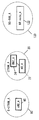
- FIG. 2 is a diagram showing details of an access network among the mobile communication systems of FIG.
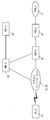
- FIG. 3 is a diagram showing details of the core network_A90 mainly in the mobile communication system of FIG.
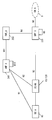
- FIG. 4 is a diagram showing details of the core network_B190 mainly in the mobile communication system of FIG.
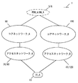
- the mobile communication system 1 in the present embodiment includes a terminal device (also referred to as a user device or mobile terminal device) UE (User Equipment) _A10, an access network (AN; Access Network) _A, and an access network _B.
- UE User Equipment
- AN Access Network
- _B access network
- the combination of access network_A and core network_A90 may be called EPS (Evolved Packet System; 4G mobile communication system), and the combination of access network_B, core network_B190 and UE_A10 is 5GS (5G System). It may be referred to as (5G mobile communication system), and the configuration of 5GS and EPS is not limited to these.
- core network_A90, core network_B190, or a combination thereof may also be referred to as a core network
- access network_A, access network_B, or a combination thereof may also be referred to as an access network or a wireless access network. It may also be referred to as DN_A5, PDN_A6 or a combination thereof.
- UE_A10 can connect to network services via 3GPP access (also referred to as 3GPP access or 3GPP access network) and / or non-3GPP access (also referred to as non-3GPP access or non-3GPP access network). It may be a device.
- UE_A10 may be provided with UICC (Universal Integrated Circuit Card) or eUICC (Embedded UICC).
- UE_A10 may be a terminal device that can be wirelessly connected, or may be an ME (Mobile Equipment), MS (Mobile Station), CIoT (Cellular Internet of Things) terminal (CIoT UE), or the like.
- 3GPP access also referred to as 3GPP access or 3GPP access network
- non-3GPP access also referred to as non-3GPP access or non-3GPP access network
- UICC Universal Integrated Circuit Card
- eUICC embedded UICC
- UE_A10 may be a terminal device that can be wirelessly connected, or may be an ME (Mobile Equipment), MS (Mobile Station
- UE_A10 can be connected to the access network and / or the core network. UE_A10 can also connect to DN_A and / or PDN_A via the access network and / or core network. UE_A10 sends and receives (communicate) user data with DN_A and / or PDN_A using a PDU (Protocol Data Unit or Packet Data Unit) session and / or PDN (Packet Data Network) connection (also called PDN connection). ). Furthermore, the communication of user data is not limited to IP (Internet Protocol) communication (IPv4 or IPv6), for example, EPS may be non-IP communication, and 5GS may be Ethernet (registered trademark) communication or Unstructured communication. There may be.
- IP Internet Protocol
- IPv4 or IPv6 IP (Internet Protocol) communication
- EPS may be non-IP communication
- 5GS may be Ethernet (registered trademark) communication or Unstructured communication. There may be.
- IP communication is data communication using IP, and is data communication realized by sending and receiving an IP packet to which an IP header is added.
- the payload portion constituting the IP packet may include user data sent and received by UE_A10.
- non-IP communication is data communication that does not use IP, and is data communication that is realized by sending and receiving data to which an IP header is not added.
- non-IP communication may be data communication realized by sending and receiving application data to which an IP address is not assigned, or UE_A10 may be provided with another header such as a Mac header or an Ethernet (registered trademark) frame header.
- User data to be sent and received may be sent and received.
- a PDU session is a connectivity established between UE_A10 and DN_A5 to provide a PDU connection service. More specifically, the PDU session may be the connectivity established between UE_A10 and the external gateway.
- the external gateway may be UPF, PGW (Packet Data Network Gateway), or the like.
- the PDU session may be a communication path established for transmitting / receiving user data between UE_A10 and the core network and / or DN, or may be a communication path for transmitting / receiving PDU.
- the PDU session may be a session established between UE_A10 and the core network and / or DN, and is a logical configuration consisting of one or more bearers or other transfer paths between each device in the mobile communication system 1.
- the PDU session may be a connection established by UE_A10 between the core network_B190 and / or an external gateway, or may be a connection established between UE_A10 and the UPF.
- the PDU session may also be connectivity and / or connection between UE_A10 and UPF_A235 via NR node_A122.
- the PDU session may be identified by a PDU session ID and / or an EPS bearer ID.
- UE_A10 can send and receive user data using a device such as an application server located in DN_A5 and a PDU session.
- the PDU session can transfer user data transmitted and received between the device such as the application server arranged in UE_A10 and DN_A5.
- each device UE_A10, device in the access network, and / or device in the core network, and / or device in the data network
- These identification information includes APN (Access Point Name), TFT (Traffic Flow Template), session type, application identification information, DN_A5 identification information, NSI (Network Slice Instance) identification information, and DCN (Dedicated Core Network).
- At least one of the identification information and the access network identification information may be included, and other information may be further included. Further, when a plurality of PDU sessions are established, the identification information associated with the PDU session may have the same content or different contents. Further, the NSI identification information is information that identifies NSI, and may be hereinafter NSI ID or Slice Instance ID.
- UTRAN Universal Terrestrial Radio Access Network
- E-UTRAN Evolved Universal Terrestrial Radio Access Network
- NG-RAN 5G-
- UTRAN_A20 and / or E-UTRAN_A80 and / or NG-RAN_A120 are referred to as 3GPP access or 3GPP access network
- wireless LAN access network and non-3GPP AN are referred to as non-3GPP access or non-3GPP access network.
- Each radio access network includes a device (for example, a base station device or an access point) to which the UE_A10 actually connects.
- E-UTRAN_A80 is an LTE access network and is configured to include one or more eNB_A45.
- eNB_A45 is a radio base station to which UE_A10 is connected by E-UTRA (Evolved Universal Terrestrial Radio Access).
- E-UTRA Evolved Universal Terrestrial Radio Access
- each eNB may be connected to each other.
- the NG-RAN_A120 is a 5G access network, which may be the (R) AN shown in FIG. 4, and includes one or more NR nodes (New Radio Access Technology node) _A122 and / or ng-eNB. It is composed.
- NR node_A122 is a radio base station to which UE_A10 is connected by 5G radio access (5G Radio Access), and is also referred to as gNB.
- the ng-eNB may be an eNB (E-UTRA) that constitutes a 5G access network, may be connected to the core network_B190 via NR node_A, or may be directly connected to the core network_B190. You may be.
- E-UTRA eNB
- each NR node_A122 and / or ng-eNB may be connected to each other.
- the NG-RAN_A120 may be an access network composed of E-UTRA and / or 5G Radio Access.
- NG-RAN_A120 may contain eNB_A45, NR node_A122, or both.
- eNB_A45 and NR node_A122 may be similar devices. Therefore, NR node_A122 can be replaced with eNB_A45.
- UTRAN_A20 is an access network for 3G mobile communication systems, and is composed of RNC (Radio Network Controller) _A24 and NB (Node B) _A22.
- NB_A22 is a radio base station to which UE_A10 is connected by UTRA (Universal Terrestrial Radio Access), and UTRAN_A20 may be configured to include one or more radio base stations.
- RNC_A24 is a control unit that connects the core network_A90 and NB_A22, and UTRAN_A20 may include one or more RNCs.
- RNC_A24 may be connected to one or more NB_A22s.
- UE_A10 is connected to each radio access network means that it is connected to a base station device, an access point, or the like included in each radio access network, and data, signals, etc. to be transmitted and received. It also means that it goes through a base station device or an access point.
- the control message sent and received between UE_A10 and the core network_B190 may be the same control message regardless of the type of access network. Therefore, the fact that UE_A10 and the core network_B190 send and receive messages via NR node_A122 may be the same as that UE_A10 and core network_B190 send messages via eNB_A45.
- the access network is a wireless network connected to UE_A10 and / or the core network.
- the access network may be a 3GPP access network or a non-3GPP access network.
- the 3GPP access network may be UTRAN_A20, E-UTRAN_A80, NG-RAN (Radio Access Network) _A120, and the non-3GPP access network may be a wireless LAN access point (WLAN AN).
- UE_A10 may be connected to the access network in order to connect to the core network, or may be connected to the core network via the access network.
- DN_A5 and PDN_A6 are data networks (Data Networks) that provide communication services to UE_A10, and may be configured as a packet data service network or may be configured for each service. Further, DN_A5 may include a connected communication terminal. Therefore, connecting to DN_A5 may be connecting to a communication terminal or server device arranged in DN_A5. Further, sending and receiving user data to and from DN_A5 may be sending and receiving user data to and from a communication terminal or server device arranged in DN_A5. Further, although DN_A5 is outside the core network in FIG. 1, it may be inside the core network.
- Data Networks Data Networks
- the core network_A90 and / or the core network_B190 may be configured as devices in one or more core networks.
- the device in the core network may be a device that executes a part or all of the processing or function of each device included in the core network_A90 and / or the core network_B190.
- the device in the core network may be referred to as a core network device.
- the core network is an IP mobile communication network operated by a mobile network operator (MNO; Mobile Network Operator) connected to an access network and / or DN.
- the core network may be a core network for a mobile communication operator that operates and manages the mobile communication system 1, or a virtual mobile communication operator such as MVNO (Mobile Virtual Network Operator) or MVNE (Mobile Virtual Network Enabler) or virtual. It may be a core network for mobile communication service providers.
- the core network_A90 may be an EPC (Evolved Packet Core) that constitutes an EPS (Evolved Packet System), and the core network_B190 may be a 5GC (5G Core Network) that constitutes a 5GS.
- EPC Evolved Packet Core
- EPS Evolved Packet System
- 5G Core Network 5GC
- the core network_B190 may be the core network of the system that provides the 5G communication service.
- the EPC may be the core network_A90 and the 5GC may be the core network_B190.
- the core network_A90 and / or the core network_B190 is not limited to this, and may be a network for providing a mobile communication service.
- the core network_A90 includes HSS (Home Subscriber Server) _A50, AAA (Authentication Authorization Accounting), PCRF (Policy and Charging Rules Function), PGW_A30, ePDG, SGW_A35, MME (Mobility Management Entity) _A40, SGSN (Serving GPRS Support). Node), SCEF, at least one may be included. And these may be configured as NF (Network Function). NF may refer to a processing function configured in the network.
- the core network_A90 can be connected to a plurality of radio access networks (UTRAN_A20, E-UTRAN_A80).
- FIG. 3 shows only HSS (HSS_A50), PGW (PGW_A30), SGW (SGW_A35) and MME (MME_A40), but other devices and / or NFs. Does not mean that is not included.
- UE_A10 is also referred to as UE
- HSS_A50 is referred to as HSS
- PGW_A30 is referred to as PGW
- SGW_A35 is referred to as SGW
- MME_A40 is referred to as MME
- DN_A5 and / or PDN_A6 is also referred to as DN or PDN.
- PGW_A30 is a relay device that is connected to DN, SGW_A35, ePDG, WLAN ANa70, PCRF, and AAA, and transfers user data as a gateway between DN (DN_A5 and / or PDN_A6) and core network_A90.
- PGW_A30 may be a gateway for IP communication and / or non-IP communication.
- PGW_A30 may have a function of transferring IP communication, and may have a function of converting non-IP communication and IP communication.
- a plurality of such gateways may be arranged in the core network_A90. Further, the plurality of gateways to be arranged may be a gateway connecting the core network_A90 and a single DN.
- the U-Plane (User Plane; UP) may be a communication path for transmitting and receiving user data, and may be composed of a plurality of bearers.
- the C-Plane (Control Plane; CP) may be a communication path for transmitting and receiving control messages, and may be composed of a plurality of bearers.
- PGW_A30 may be connected to SGW and DN and UPF (User Plane Function) and / or SMF (Session Management Function), or may be connected to UE_A10 via U-Plane.
- PGW_A30 may be configured with UPF_A235 and / or SMF_A230.
- SGW_A35 is connected to PGW_A30, MME_A40, E-UTRAN_A80, SGSN and UTRAN_A20, and is a relay that transfers user data as a gateway between core network_A90 and 3GPP access networks (UTRAN_A20, GERAN, E-UTRAN_A80). It is a device.
- MME_A40 is a control device that is connected to SGW_A35, an access network, HSS_A50, and SCEF, and performs location information management including mobility management of UE_A10 and access control via the access network. Further, the MME_A40 may include a function as a session management device that manages the sessions established by the UE_A10. Further, a plurality of such control devices may be arranged in the core network_A90, and for example, a position management device different from the MME_A40 may be configured. A location management device different from the MME_A40 may be connected to the SGW_A35, the access network, the SCEF, and the HSS_A50, similar to the MME_A40. Furthermore, MME_A40 may be connected to AMF (Access and Mobility Management Function).
- AMF Access and Mobility Management Function
- the MMEs may be connected to each other.
- the context of UE_A10 may be transmitted and received between MMEs.
- the MME_A40 is a management device that transmits and receives control information related to mobility management and session management to and from UE_A10, in other words, it may be a control plane (Control Plane; C-Plane; CP) control device.
- MME_A40 may be one or more core networks or a management device composed of DCN or NSI, or one or more core networks or. It may be a management device connected to a DCN or NSI.
- the plurality of DCNs or NSIs may be operated by a single telecommunications carrier or may be operated by different telecommunications carriers.
- MME_A40 may be a relay device that transfers user data as a gateway between the core network_A90 and the access network.
- the user data transmitted / received using MME_A40 as a gateway may be small data.
- MME_A40 may be an NF that plays a role of mobility management such as UE_A10, or an NF that manages one or more NSIs. In addition, MME_A40 may be an NF that plays one or more of these roles.
- the NF may be one or more devices arranged in the core network_A90, and may also be a CP function for control information and / or a control message (hereinafter, CPF (Control Plane Function) or Control Plane Network Function). It may be a shared CP function shared between multiple network slices.
- NF is a processing function configured in the network. That is, the NF may be a functional device such as MME, SGW, PGW, CPF, AMF, SMF, UPF, or functional or capability information such as MM (Mobility Management) or SM (Session Management). Further, the NF may be a functional device for realizing a single function, or may be a functional device for realizing a plurality of functions. For example, the NF for realizing the MM function and the NF for realizing the SM function may exist separately, or there is an NF for realizing both the MM function and the SM function. You may.
- HSS_A50 is a management node that is connected to MME_A40, AAA, and SCEF and manages subscriber information.
- the subscriber information of HSS_A50 is referred to, for example, when controlling access to MME_A40.
- the HSS_A50 may be connected to a position management device different from that of the MME_A40.
- HSS_A50 may be connected to CPF_A140.
- HSS_A50 and UDM (Unified Data Management) _A245 may be configured as different devices and / or NFs, or may be configured as the same device and / or NFs.
- AAA is connected to PGW30, HSS_A50, PCRF, and WLAN ANa70, and controls access to UE_A10, which is connected via WLAN ANa70.
- PCRF is connected to PGW_A30, WLAN ANa75, AAA, DN_A5 and / or PDN_A6, and performs QoS management for data delivery. For example, it manages the QoS of the communication path between UE_A10 and DN_A5 and / or PDN_A6. Further, the PCRF may be a device that creates and / or manages PCC (Policy and Charging Control) rules and / or routing rules that each device uses when transmitting and receiving user data.
- PCC Policy and Charging Control
- the PCRF may also be a PCF that creates and / or manages policies. More specifically, the PCRF may be connected to UPF_A235.
- the ePDG is connected to PGW30 and WLAN ANb75, and delivers user data as a gateway between core network _A90 and WLAN ANb75.
- the SGSN is connected to UTRAN_A20, GERAN and SGW_A35, and is a control device for position management between the 3G / 2G access network (UTRAN / GERAN) and the LTE (4G) access network (E-UTRAN). Is.
- the SGSN has a PGW and SGW selection function, a UE_A10 time zone management function, and an MME_A40 selection function during handover to E-UTRAN.
- SCEF is a relay device that is connected to DN_A5 and / or PDN_A6, MME_A40, and HSS_A50 and transfers user data as a gateway that connects DN_A5 and / or PDN_A6 and core network_A90.
- SCEF may be a gateway for non-IP communication.
- SCEF may have the ability to convert between non-IP communication and IP communication.
- a plurality of such gateways may be arranged in the core network_A90.
- multiple gateways connecting the core network_A90 with a single DN_A5 and / or PDN_A6 and / or DN may also be deployed.
- the SCEF may be configured outside the core network or inside the core network.
- the core network_B190 includes AUFF (Authentication Server Function), AMF (Access and Mobility Management Function) _A240, UDSF (Unstructured Data Storage Function), NEF (Network Exposure Function), NRF (Network Repository Function), PCF (Policy Control). Function), SMF (Session Management Function) _A230, UDM (Unified Data Management), UPF (User Plane Function) _A235, AF (Application Function), N3IWF (Non-3GPP InterWorking Function) may be included. .. And these may be configured as NF (Network Function). NF may refer to a processing function configured in the network.
- FIG. 4 shows only AMF (AMF_A240), SMF (SMF_A230), and UPF (UPF_A235), but other than these (device and / or NF (Network)). It does not mean that Function)) is not included.
- AMF_A240 is referred to as AMF
- SMF_A230 is referred to as SMF
- UPF_A235 is referred to as UPF
- DN_A5 is also referred to as DN.
- Fig. 4 shows the N1 interface (hereinafter, also referred to as reference point), N2 interface, N3 interface, N4 interface, N6 interface, N9 interface, and N11 interface.
- the N1 interface is the interface between the UE and AMF
- the N2 interface is the interface between (R) AN (access network) and AMF
- the N3 interface is (R) AN (access network).
- the interface between UPF, the N4 interface is the interface between SMF and UPF
- the N6 interface is the interface between UPF and DN
- the N9 interface is the interface between UPF and UPF.
- N11 interface is the interface between AMF and SMF. Communication can be performed between the devices by using these interfaces.
- (R) AN is also referred to as NG RAN below.
- AMF_A240 is connected to other AMF, SMF (SMF_A230), access network (that is, UTRAN_A20 and E-UTRAN_A80 and NG-RAN_A120), UDM, AUSF, PCF.
- AMF_A240 is used for registration management (Registration management), connection management (Connection management), reachability management (Reachability management), mobility management such as UE_A10 (Mobility management), and transfer of SM (Session Management) messages between UE and SMF.
- SMF Session Management
- AMF_A240s may be arranged in the core network_B190.
- AMF_A240 may be an NF that manages one or more NSIs (Network Slice Instances).
- AMF_A240 may be a shared CP function (CCNF; Common CPNF (Control Plane Network Function)) shared among a plurality of NSIs.
- CCNF Common CPNF (Control Plane Network Function)
- the RM state includes a non-registered state (RM-DEREGISTERED state) and a registered state (RM-REGISTERED state).
- RM-DEREGISTERED state the UE is not registered in the network, so the UE context in AMF does not have valid location information or routing information for that UE, so AMF cannot reach the UE. is there.
- the UE is registered in the network, so the UE can receive services that require registration with the network.
- CM-IDLE state a non-connected state
- CM-CONNECTED state a connected state
- N2 connection an N2 interface connection
- N3 connection an N3 interface connection
- the UE may have an N2 interface connection (N2 connection) and / or an N3 interface connection (N3 connection).
- SMF_A230 has session management (Session Management; SM; session management) functions such as PDU sessions, IP address allocation to UEs and its management functions, UPF selection and control functions, and traffic to appropriate destinations.
- UPF setting function for routing function to notify that downlink data has arrived (Downlink Data Notification), AN-specific (AN) transmitted to AN via AMF via N2 interface It may have a function of providing SM information (for each session), a function of determining an SSC mode (Session and Service Continuity mode) for a session, a roaming function, and the like.
- SMF_A230 may be connected to AMF_A240, UPF_A235, UDM, and PCF.
- UPF_A235 is connected to DN_A5, SMF_A230, other UPFs, and access networks (that is, UTRAN_A20 and E-UTRAN_A80 and NG-RAN_A120).
- UPF_A235 is an anchor for intra-RAT mobility or inter-RAT mobility, packet routing & forwarding, UL CL (Uplink Classifier) function that supports routing of multiple traffic flows to one DN, Routing point function that supports multi-homed PDU session, QoS processing for userplane, verification of uplink traffic, buffering of downlink packet, downlink data notification (Downlink Data Notification) It may play a role such as a trigger function.
- UL CL Uplink Classifier
- UPF_A235 may be a relay device that transfers user data as a gateway between DN_A5 and core network_B190.
- UPF_A235 may be a gateway for IP communication and / or non-IP communication.
- UPF_A235 may have a function of transferring IP communication, and may have a function of converting non-IP communication and IP communication.
- the plurality of gateways to be arranged may be a gateway connecting the core network_B190 and a single DN.
- the UPF_A235 may have connectivity with other NFs, or may be connected to each device via other NFs.
- UPF_C239 (also referred to as branching point or uplink classifier), which is a UPF different from UPF_A235, may exist as a device or NF between UPF_A235 and the access network. If UPF_C239 is present, the PDU session between UE_A10 and DN_A5 will be established via the access network, UPF_C239, UPF_A235.
- AUSF is connected to UDM and AMF_A240. AUSF acts as an authentication server.
- UDSF provides a function for all NFs to store and retrieve information as unstructured data.
- NEF provides a means to safely provide the services and capabilities provided by the 3GPP network.
- Information received from other NFs is saved as structured data.
- NRF When NRF receives an NF discovery request (NF Discovery Request) from an NF instance, it provides information on the discovered NF instance to that NF, and information on available NF instances and services supported by that instance. Or hold.
- NF Discovery Request NF Discovery Request
- PCF is connected to SMF (SMF_A230), AF, AMF_A240. Provide policy rules, etc.
- UDM is connected to AMF_A240, SMF (SMF_A230), AUSF, PCF.
- UDM includes UDM FE (application front end) and UDR (User Data Repository).
- UDM FE processes authentication information (credentials), location management (location management), subscription management (subscription management), and the like.
- UDR stores the data required by UDM FE and the policy profiles required by PCF.
- AF is connected to PCF. AF influences traffic routing and participates in policy control.
- N3IWF establishes IPsec tunnel with UE, relays NAS (N1) signaling between UE and AMF, processes N2 signaling transmitted from SMF and relayed by AMF, establishment of IPsec Security Association (IPsec SA). , Provides functions such as relaying userplane packets between UE and UPF, and AMF selection.
- IPsec SA IPsec Security Association
- S1 mode is a UE mode that allows sending and receiving of messages using the S1 interface.
- the S1 interface may be composed of an S1-MME interface, an S1-U interface, and an X2 interface that connects radio base stations.
- the UE in S1 mode can, for example, access the EPC via eNB that provides the E-UTRA function and access the EPC via en-gNB that provides the NR function.
- the S1 mode is used for access to the EPC via eNB that provides the E-UTRA function and access to the EPC via en-gNB that provides the NR function, but each may be configured as a different mode. ..
- N1 mode is a UE mode in which the UE can access 5GC via a 5G access network. Further, the N1 mode may be a UE mode capable of transmitting and receiving messages using the N1 interface.
- the N1 interface may be composed of an N1 interface and an Xn interface that connects radio base stations.
- UE in N1 mode can, for example, access 5GC via ng-eNB that provides E-UTRA function and access 5GC via gNB that provides NR function.
- Access to 5GC via ng-eNB that provides the E-UTRA function and access to 5GC via gNB that provides the NR function are set to N1 mode, but they may be configured as different modes individually. ..
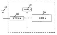
- UE_A10 is composed of a control unit_A500, a transmission / reception unit_A520, and a storage unit_A540.
- the transmission / reception unit_A520 and the storage unit_A540 are connected to the control unit_A500 via a bus.
- An external antenna 410 is connected to the transmitter / receiver _A520.
- the control unit_A500 is a functional unit for controlling the entire UE_A10, and realizes various processes of the entire UE_A10 by reading and executing various information and programs stored in the storage unit_A540.
- the transmitter / receiver_A520 is a functional unit for UE_A10 to connect to the base stations (UTRAN_A20 and E-UTRAN_A80 and NG-RAN_A120) and / or wireless LAN access point (WLAN AN) in the access network and to connect to the access network. is there.
- the UE_A10 can be connected to a base station and / or an access point in the access network via an external antenna 410 connected to the transmitter / receiver_A520.
- the UE_A10 transmits / receives user data and / or control information to / from a base station and / or an access point in the access network via an external antenna 410 connected to the transmission / reception unit_A520. Can be done.
- the storage unit_A540 is a functional unit that stores programs and data required for each operation of UE_A10, and is composed of, for example, a semiconductor memory, an HDD (Hard Disk Drive), an SSD (Solid State Drive), and the like.
- the storage unit_A540 stores identification information, control information, flags, parameters, rules, policies, etc. included in control messages transmitted and received in the communication procedure described later.
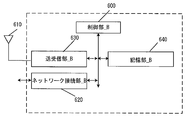
- the eNB_A45 and the NR node_A122 are composed of a control unit_B600, a network connection unit_B620, a transmission / reception unit_B630, and a storage unit_B640.
- the network connection unit_B620, the transmission / reception unit_B630, and the storage unit_B640 are connected to the control unit_B600 via a bus.
- An external antenna 510 is connected to the transmitter / receiver _B630.
- the control unit_B600 is a functional unit for controlling the entire eNB_A45 and NR node_A122, and by reading and executing various information and programs stored in the storage unit_B640, the entire eNB_A45 and NR node_A122 can be read and executed. Realize various processes.
- the network connection part_B620 is a functional part for eNB_A45 and NR node_A122 to connect with AMF_A240 and UPF_A235 in the core network.
- eNB_A45 and NR node_A122 can be connected to AMF_A240 and UPF_A235 in the core network via the network connection part_B620.
- the eNB_A45 and NR node_A122 can send and receive user data and / or control information to and from the AMF_A240 and / or UPF_A235 via the network connection unit_B620.
- the transmission / reception unit_B630 is a functional unit for eNB_A45 and NR node_A122 to connect to UE_A10.
- the eNB_A45 and NR node_A122 can send and receive user data and / or control information to and from the UE_A10 via the transmission / reception unit_B630.
- the storage unit_B640 is a functional unit that stores programs and data required for each operation of eNB_A45 and NR node_A122.
- the storage unit_B640 is composed of, for example, a semiconductor memory, an HDD, an SSD, or the like.
- the storage unit_B640 stores identification information, control information, flags, parameters, etc. included in the control messages transmitted and received in the communication procedure described later.
- the storage unit_B640 may store this information as a context for each UE_A10.
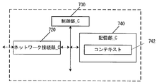
- the MME_A40 or AMF_A240 is composed of a control unit_C700, a network connection unit_C720, and a storage unit_C740.
- the network connection unit_C720 and the storage unit_C740 are connected to the control unit_C700 via a bus.
- the storage unit_C740 stores the context 642.
- the control unit_C700 is a functional unit for controlling the entire MME_A40 or AMF_A240, and realizes various processes of the entire AMF_A240 by reading and executing various information and programs stored in the storage unit_C740. To do.
- MME_A40 or AMF_A240 is another MME_A40, AMF_240, SMF_A230, base stations in the access network (UTRAN_A20 and E-UTRAN_A80 and NG-RAN_A120) and / or wireless LAN access point (WLAN AN), UDM. , AUSF, a functional part for connecting to PCF.
- the MME_A40 or AMF_A240 sends and receives user data and / or control information to and from the base station and / or access point, UDM, AUSF, PCF in the access network via the network connection_C720. Can be done.
- the storage unit_C740 is a functional unit that stores programs and data required for each operation of MME_A40 or AMF_A240.
- the storage unit_C740 is composed of, for example, a semiconductor memory, an HDD, an SSD, or the like.
- the storage unit_C740 stores identification information, control information, flags, parameters, and the like included in the control messages transmitted and received in the communication procedure described later.
- the context 642 stored in the storage unit_C740 may include a context stored for each UE, a context stored for each PDU session, and a context stored for each bearer.
- the contexts stored for each UE include IMSI, MSISDN, MMState, GUTI, MEIdentity, UERadioAccessCapability, UENetworkCapability, MSNetworkCapability, AccessRestriction, MMEF-TEID, SGWF-TEID, eNBAddress. , MMEUES1APID, eNBUES1APID, NRnodeAddress, NRnodeID, WAGAddress, WAGID may be included. Further, the context stored for each PDU session may include APN in Use, Assigned Session Type, IP Address (es), PGW F-TEID, SCEF ID, and Default bearer.
- the contexts stored for each bearer are EPSBearerID, TI, TFT, SGWF-TEID, PGWF-TEID, MMEF-TEID, eNBAddress, NRnodeAddress, WAGAddress, eNBID, NRnode. ID and WAG ID may be included.
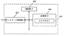
- the SMF_A230 is composed of a control unit_D800, a network connection unit_D820, and a storage unit_D840, respectively.
- the network connection unit _D820 and the storage unit _D840 are connected to the control unit _D800 via a bus.
- the storage unit_D840 stores the context 742.
- the control unit_D800 of SMF_A230 is a functional unit for controlling the entire SMF_A230, and realizes various processes of the entire SMF_A230 by reading and executing various information and programs stored in the storage unit_D840. To do.
- the network connection part_D820 of SMF_A230 is a functional part for SMF_A230 to connect with AMF_A240, UPF_A235, UDM, and PCF.
- the SMF_A230 can send and receive user data and / or control information to and from the AMF_A240, UPF_A235, UDM, and PCF via the network connection _D820.
- the storage unit_D840 of SMF_A230 is a functional unit that stores programs and data required for each operation of SMF_A230.
- the storage unit_D840 of the SMF_A230 is composed of, for example, a semiconductor memory, an HDD, an SSD, or the like.
- the storage unit_D840 of SMF_A230 stores identification information, control information, flags, parameters, etc. included in the control messages transmitted and received in the communication procedure described later.
- the context 742 stored in the storage unit_D840 of SMF_A230 includes a context stored for each UE, a context stored for each APN, a context stored for each PDU session, and a context stored for each bearer. There may be a context.
- the context stored for each UE may include IMSI, MEIdentity, MSISDN, and RATtype.
- the context stored for each APN may include APN in use.
- the context stored for each APN may be stored for each Data Network Identifier.
- the context stored for each PDU session may include AssignedSessionType, IPAddress (es), SGWF-TEID, PGWF-TEID, DefaultBearer.
- the context stored for each bearer may include EPS Bearer ID, TFT, SGW F-TEID, and PGW F-TEID.
- PGW_A30 or UPF_A235 is composed of a control unit_D800, a network connection unit_D820, and a storage unit_D840, respectively.
- the network connection unit _D820 and the storage unit _D840 are connected to the control unit _D800 via a bus.
- the storage unit_D840 stores the context 742.
- the control unit_D800 of PGW_A30 or UPF_A235 is a functional unit for controlling the entire PGW_A30 or UPF_A235, and by reading and executing various information and programs stored in the storage unit_D840, PGW_A30 or UPF_A235 Realize various processing as a whole.
- the network connection part_D820 of PGW_A30 or UPF_A235 connects PGW_A30 or UPF_A235 to DN (that is, DN_A5), SMF_A230, other UPF_A235, and access networks (that is, UTRAN_A20 and E-UTRAN_A80 and NG-RAN_A120). It is a functional part to do.
- UPF_A235 is connected to the DN (ie DN_A5), SMF_A230, other UPF_A235, and the access network (ie UTRAN_A20 and E-UTRAN_A80 and NG-RAN_A120) via the network connection_D820.
- User data and / or control information can be sent and received.
- the storage unit_D840 of UPF_A235 is a functional unit that stores programs, data, etc. required for each operation of UPF_A235.
- the storage unit_D840 of UPF_A235 is composed of, for example, a semiconductor memory, an HDD, an SSD, or the like.
- the storage unit_D840 of UPF_A235 stores identification information, control information, flags, parameters, etc. included in the control messages transmitted and received in the communication procedure described later.
- the context 742 stored in the storage unit_D840 of UPF_A235 the context stored for each UE, the context stored for each APN, the context stored for each PDU session, and the context stored for each bearer are stored. There may be a context.
- the context stored for each UE may include IMSI, MEIdentity, MSISDN, and RATtype.
- the context stored for each APN may include APN in use.
- the context stored for each APN may be stored for each Data Network Identifier.
- the context stored for each PDU session may include AssignedSessionType, IPAddress (es), SGWF-TEID, PGWF-TEID, DefaultBearer.
- the context stored for each bearer may include EPS Bearer ID, TFT, SGW F-TEID, and PGW F-TEID.
- IMSI International Mobile Subscriber Identity
- MME_A40 / CPF_A140 / AMF_A2400 and SGW_A35 may be equal to the IMSI stored by HSS_A50.
- EMM State / MM State indicates the mobility management state of UE_A10 or MME_A40 / CPF_A140 / AMF_A240.
- the EMM State / MM State may be an EMM-REGISTERED state (registered state) in which UE_A10 is registered in the network, and / or an EMM-DEREGISTERD state (unregistered state) in which UE_A10 is not registered in the network.
- the EMM State / MM State may be an ECM-CONNECTED state in which the connection between UE_A10 and the core network is maintained, and / or an ECM-IDLE state in which the connection is released.
- the EMM State / MM State may be information that can distinguish between the state in which UE_A10 is registered in the EPC and the state in which it is registered in the NGC or 5GC.
- GUTI Globally Unique Temporary Identity
- MME_A40 / CPF_A140 / AMF_A240 identification information GUMMEI (Globally Unique MME Identifier)
- M-TMSI M-Temporary Mobile Subscriber Identity
- MEIdentity is UE_A10 or ME ID, and may be, for example, IMEI (International Mobile Equipment Identity) or IMEISV (IMEI Software Version).
- MSISDN represents the basic telephone number of UE_A10.
- the MSISDN stored by MME_A40 / CPF_A140 / AMF_A240 may be the information indicated by the storage unit of HSS_A50.
- GUTI may include information for identifying CPF_140.
- MME F-TEID is information that identifies MME_A40 / CPF_A140 / AMF_A240.
- the MME F-TEID may include the IP address of MME_A40 / CPF_A140 / AMF_A240, the TEID (Tunnel Endpoint Identifier) of MME_A40 / CPF_A140 / AMF_A240, or both of them. May be good.
- the IP address of MME_A40 / CPF_A140 / AMF_A240 and the TEID of MME_A40 / CPF_A140 / AMF_A240 may be stored independently.
- the MME F-TEID may be identification information for user data or identification information for control information.
- SGW F-TEID is information that identifies SGW_A35.
- the SGW F-TEID may include the IP address of SGW_A35, the TEID of SGW_A35, or both of them. Further, the IP address of SGW_A35 and the TEID of SGW_A35 may be stored independently. Further, the SGW F-TEID may be identification information for user data or identification information for control information.
- PGW F-TEID is information that identifies PGW_A30 / UPGW_A130 / SMF_A230 / UPF_A235.
- the PGW F-TEID may include the IP address of PGW_A30 / UPGW_A130 / SMF_A230 / UPF_A235, the TEID of PGW_A30 / UPGW_A130 / SMF_A230 / UPF_A235, or both. Good.
- the IP address of PGW_A30 / UPGW_A130 / SMF_A230 / UPF_A235 and the TEID of PGW_A30 / UPGW_A130 / SMF_A230 / UPF_A235 may be stored independently.
- the PGW F-TEID may be identification information for user data or identification information for control information.
- ENB F-TEID is information that identifies eNB_A45.
- the eNB F-TEID may include the IP address of eNB_A45, the TEID of eNB_A45, or both of them. Further, the IP address of eNB_A45 and the TEID of SGW_A35 may be stored independently. Further, the eNB F-TEID may be identification information for user data or identification information for control information.
- APN may be identification information that identifies the core network and the external network such as DN. Furthermore, the APN can also be used as information for selecting a gateway such as PGW_A30 / UPGW_A130 / UPF_A235 that connects the core network_A90.
- the APN may be a DNN (Data Network Name). Therefore, APN may be expressed as DNN, and DNN may be expressed as APN.
- the APN may be identification information that identifies such a gateway, or identification information that identifies an external network such as a DN.
- the APN may be identification information that identifies such a gateway, or identification information that identifies an external network such as a DN.
- UERadioAccessCapability is identification information indicating the wireless access capability of UE_A10.
- UENetworkCapability includes security algorithms and key derivation functions supported by UE_A10.
- MS Network Capability is information that includes one or more information required for SGSN_A42 for UE_A10 having GERAN_A25 and / or UTRAN_A20 functions.
- Access Restriction is registration information for access restrictions.
- eNB Address is the IP address of eNB_A45.
- the MMEUES1APID is information that identifies UE_A10 in MME_A40 / CPF_A140 / AMF_A240.
- the eNB UES1AP ID is information that identifies UE_A10 in eNB_A45.
- APN in Use is a recently used APN.
- APN in Use may be a Data Network Identifier. This APN may consist of network identification information and default operator identification information. Further, APN in Use may be information that identifies the DN at which the PDU session is established.
- Assigned Session Type is information indicating the type of PDU session. Assigned Session Type may be Assigned PDN Type. The type of PDU session can be IP or non-IP. In addition, if the type of PDU session is IP, it may further include information indicating the type of PDN assigned by the network. The Assigned Session Type may be IPv4, IPv6, or IPv4 v6.
- IP Address is the IP address assigned to the UE.
- the IP address may be an IPv4 address, an IPv6 address, an IPv6 prefix, or an interface ID. If the Assigned Session Type indicates non-IP, the IP Address element may not be included.
- DNN is identification information that distinguishes the core network_B190 from an external network such as DN. Furthermore, DNN can also be used as information for selecting a gateway such as UPGW_A130 or PF_A235 to connect the core network_B190.
- the DNN may be identification information that identifies such a gateway, or identification information that identifies an external network such as a DN.
- identification information that identifies such a gateway
- identification information that identifies an external network such as a DN.
- the DNN may be information equal to the APN or information different from the APN.
- each device may manage the information indicating the correspondence between the DNN and the APN, or may carry out a procedure for inquiring the APN using the DNN. You may carry out the procedure to inquire about DNN using APN.
- SCEFID is the IP address of SCEF_A46 used in the PDU session.
- the Default Bearer is information acquired and / or generated when the PDU session is established, and is EPS bearer identification information for identifying the default bearer associated with the PDU session.
- EPS Bearer ID is the identification information of EPS bearer. Further, the EPS Bearer ID may be identification information for identifying SRB (Signalling Radio Bearer) and / or CRB (Control-plane Radio bearer), or may be identification information for identifying DRB (Data Radio Bearer).
- TI Transaction Identifier
- the EPS Bearer ID may be EPS bearer identification information that identifies the dedicated bearer. Therefore, the identification information that identifies the EPS bearer different from the default bearer may be used. TFT shows all packet filters associated with EPS bearers.
- the TFT is information that identifies a part of the user data to be transmitted / received, and UE_A10 transmits / receives the user data identified by the TFT using the EPS bearer associated with the TFT.
- UE_A10 sends and receives user data identified by the TFT using RB (Radio Bearer) associated with the TFT.
- the TFT may associate user data such as application data to be transmitted / received with an appropriate transfer path, or may be identification information for identifying application data.
- UE_A10 may send and receive user data that cannot be identified by the TFT using the default bearer.
- UE_A10 may also store the TFT associated with the default bearer in advance.
- Default Bearer is EPS bearer identification information that identifies the default bearer associated with the PDU session.
- the EPS bearer may be a logical communication path established between UE_A10 and PGW_A30 / UPGW_A130 / UPF_A235, or may be a communication path constituting a PDN connection / PDU session. Further, the EPS bearer may be a default bearer or a dedicated bearer.
- the EPS bearer may be configured to include an RB established between UE_A10 and a base station and / or access point in the access network. In addition, RBs and EPS bearers may have a one-to-one correspondence.
- the RB identification information may be associated with the EPS bearer identification information on a one-to-one basis, or may be the same identification information.
- the RB may be SRB and / or CRB, or may be DRB.
- the Default Bearer may be information acquired by UE_A10 and / or SGW_A35 and / or PGW_A30 / UPGW_A130 / SMF_A230 / UPF_A235 from the core network when the PDU session is established.
- the default bearer is an EPS bearer that is first established in a PDN connection / PDU session, and is an EPS bearer that can be established only once in one PDN connection / PDU session.
- the default bearer may be an EPS bearer that can be used to communicate user data that is not associated with a TFT.
- a decadeted bearer is an EPS bearer that is established after the default bearer is established in a PDN connection / PDU session, and is an EPS bearer that can be established multiple times in one PDN connection / PDU session. is there.
- a decadeted bearer is an EPS bearer that can be used to communicate user data associated with a TFT.
- User Identity is information that identifies the subscriber. User Identity may be IMSI or MSISDN. Further, User Identity may be identification information other than IMSI and MSISDN. Serving Node Information is information that identifies MME_A40 / CPF_A140 / AMF_A240 used in the PDU session, and may be the IP address of MME_A40 / CPF_A140 / AMF_A240.
- ENB Address is the IP address of eNB_A45.
- the eNB ID is information that identifies the UE in eNB_A45.
- MMEAddress is the IP address of MME_A40 / CPF_A140 / AMF_A240.
- the MME ID is information that identifies MME_A40 / CPF_A140 / AMF_A240.
- NR nodeAddress is the IP address of NR node_A122.
- the NR node ID is information that identifies the NR node_A122.
- WAGAddress is the IP address of WAG.
- WAG ID is information that identifies WAG.
- Anchor or anchor point is a UFP that has a gateway function for DN and PDU sessions.
- the UPF serving as an anchor point may be a PDU session anchor or an anchor.
- the SSC mode indicates the mode of service session continuity (Session and Service Continuity) supported by the system and / or each device in 5GC. More specifically, it may be a mode indicating the types of service session continuation supported by the PDU session established between UE_A10 and the anchor point).
- the anchor point may be UPGW or UPF_A235.
- SSC mode may be a mode indicating the type of service session continuation set for each PDU session. Further, the SSC mode may be composed of three modes, SSC mode 1, SSC mode 2, and SSC mode 3. The SSC mode is associated with the anchor point and cannot be changed while the PDU session is established.
- SSC mode 1 in the present embodiment is a service session continuation mode in which the same UPF is maintained as an anchor point regardless of access technologies such as RAT (Radio Access Technology) and cells used when UE_A10 connects to the network.
- SSC mode1 may be a mode that realizes the continuation of the service session without changing the anchor point used by the established PDU session even when the mobility of UE_A10 occurs.
- SSC mode2 in the present embodiment includes an anchor point associated with one SSC mode2 in the PDU session, the service session continuation in which the PDU session is released first and then the PDU session is established continuously.
- the mode More specifically, SSC mode2 is a mode in which when an anchor point relocation occurs, the PDU session is deleted once and then a new PDU session is established.
- SSC mode2 is a service session continuation mode in which the same UPF is maintained as an anchor point only within the serving area of the UPF. More specifically, SSC mode2 may be a mode that realizes service session continuation without changing the UPF used by the established PDU session as long as UE_A10 is within the serving area of the UPF. Furthermore, SSC mode2 is a mode that realizes service session continuation by changing the UPF used by the established PDU session when the mobility of UE_A10 occurs, such as leaving the serving area of the UPF. Good.
- the TUPF serving area may be an area where one UPF can provide the service session continuation function, or a subset of the access network such as RAT and cell used when UE_A10 connects to the network. It may be. Further, the subset of the access network may be a network composed of one or more RATs and / or cells, or may be a TA.
- SSC mode 3 in the present embodiment is a service session continuation mode in which a PDU session can be established between a new anchor point and the UE for the same DN without releasing the PDU session between the UE and the anchor point. is there.
- SSCmode3 will have a PDU session established between UE_A10 and the UPF, and / or a new PDU session via the new UPF for the same DN before disconnecting the communication path, and / Alternatively, it is a mode of service session continuation that allows the establishment of a communication path. Further, SSC mode 3 may be a service session continuation mode that allows UE_A10 to be multihoming.
- / or SSC mode 3 may be a mode in which the continuation of the service session using the UPF associated with a plurality of PDU sessions and / or the PDU session is permitted.
- each device may realize the service session continuation by using a plurality of PDU sessions, or may realize the service session continuation by using a plurality of TUPFs.
- the selection of the new UPF may be carried out by the network, and the new UPF is the location where UE_A10 is connected to the network. It may be the most suitable UPF.
- UE_A10 will immediately address the newly established PDU session for application and / or flow communication. It may be carried out based on the completion of communication.
- the network refers to at least a part of access network_A20 / 80, access network_B80 / 120, core network_A90, core network_B190, DN_A5, and PDN_A6.
- one or more devices included in at least a part of access network_A20 / 80, access network_B80 / 120, core network_A90, core network_B190, DN_A5, and PDN_A6 are referred to as a network or network device. You may call it. That is, the fact that the network executes the transmission / reception and / or procedure of the message means that the device (network device) in the network executes the transmission / reception and / or procedure of the message.
- the session management (SM; Session Management) message (also referred to as NAS (Non-Access-Stratum) SM message or SM message) in the present embodiment is a procedure for SM (also referred to as a session management procedure or SM procedure). It may be a NAS message used in, and may be a control message sent and received between UE_A10 and SMF_A230 via AMF_A240. Further, the SM message includes a PDU session establishment request message, a PDU session establishment acceptance message, a PDU session completion message, a PDU session rejection message, a PDU session change request message, a PDU session change acceptance message, a PDU session change rejection message, and the like. You may.
- the procedure for SM may include a PDU session establishment procedure, a PDU session change procedure, and the like.
- the message sent by UE_A10 is expressed as an SM request message.
- the PDU session establishment request message and the PDU session change request message are SM request messages.
- the tracking area (also referred to as TA; Tracking Area) in the present embodiment is a range that can be represented by the position information of UE_A10 managed by the core network, and may be composed of, for example, one or more cells. Further, the TA may be a range in which a control message such as a paging message is broadcast, or a range in which UE_A10 can move without performing a handover procedure.
- the TA list (TA list) in the present embodiment is a list including one or more TAs assigned to UE_A10 by the network. Note that UE_A10 may be able to move without executing the registration procedure while moving within one or more TAs included in the TA list. In other words, the TA list may be a set of information indicating the areas that UE_A10 can move to without performing the registration procedure.
- the network slice in the present embodiment is a logical network that provides a specific network capability and network characteristics.
- the network slice is also referred to as a NW slice.
- the NSI (Network Slice Instance) in this embodiment is an entity of a network slice (Network Slice) composed of one or more in the core network_B190. Further, the NSI in this embodiment may be composed of a virtual NF (Network Function) generated by using NST (Network Slice Template).
- NST is a logical expression of one or more NFs (Network Functions) associated with a resource request for providing a required communication service or capability.
- the NSI may be an aggregate in the core network_B190 composed of a plurality of NFs.
- NSI may be a logical network configured to divide user data delivered by services or the like. At least one or more NFs may be configured in the network slice.
- the NF configured in the network slice may or may not be a device shared with other network slices.
- UE_A10 and / or devices in the network include NSSAI and / or S-NSSAI and / or UE usage type and / or one or more network slice type IDs and / or one or more NS IDs, etc. It can be assigned to one or more network slices based on registration information and / or APN.
- S-NSSAI in this embodiment is an abbreviation for Single Network Slice Selection Assistance information, and is information for identifying a network slice.
- S-NSSAI may be composed of SST (Slice / Service type) and SD (Slice Differentiator).
- S-NSSAI may be composed only of SST, or may be composed of both SST and SD.
- SST is information indicating the operation of the network slice expected in terms of function and service.
- SD may be information that complements SST when selecting one NSI from a plurality of NSIs represented by SST.
- S-NSSAI may be information specific to each PLMN (Public Land Mobile Network), standard information shared among PLMNs, or information specific to a telecommunications carrier that differs for each PLMN. There may be.
- PLMN Public Land Mobile Network
- standard information shared among PLMNs or information specific to a telecommunications carrier that differs for each PLMN. There may be.
- SST and / or SD may be standard information (Standard Value) shared among PLMNs, or information specific to a telecommunications carrier (Non Standard Value) that differs for each PLMN. You may.
- the network may store one or more S-NSSAI in the registration information of UE_A10 as the default S-NSSAI.
- NSSAI Single Network Slice Selection Assistance information
- UE_A10 may store the NSSAI permitted from the network for each PLMN.
- NSSAI may be the information used to select AMF_A240.
- the operator A network in this embodiment is a network operated by network operator A (operator A).
- the operator A may develop a NW slice common to the operator B described later.
- the operator B network in this embodiment is a network operated by network operator B (operator B).
- operator B may develop a NW slice common to operator A.
- the first NW slice in this embodiment is the NW slice to which the established PDU session belongs when the UE connects to a specific DN.
- the first NW slice may be a NW slice managed in the operator A network or a NW slice commonly managed in the operator B network.
- the second NW slice in the present embodiment is a NW slice to which another PDU session that can connect to the DN to which the PDU session belonging to the first NW slice belongs belongs.
- the first NW slice and the second NW slice may be operated by the same operator or may be operated by different operators.
- the equal PLMN (equivalent PLMN) in the present embodiment is a PLMN that is treated as if it is the same PLMN as any PLMN in the network.
- the DCN (Dedicated Core Network) in this embodiment is a core network dedicated to a specific subscriber type, which is composed of one or more in the core network_A90.
- a DCN for a UE registered as a user of an M2M (Machine to Machine) communication function may be configured in the core network_A90.
- a default DCN may be configured within core network_A90 for UEs that do not have a suitable DCN.
- the DCN may be populated with at least one MME_40 or SGSN_A42, and may further be populated with at least one SGW_A35 or PGW_A30 or PCRF_A60.
- the DCN may be identified by the DCN ID, and the UE may be assigned to one DCN based on information such as the UE usage type and / or the DCN ID.
- the first timer in this embodiment is a timer that manages the start of a procedure for session management such as a PDU session establishment procedure and / or the transmission of an SM (Session Management) message such as a PDU session establishment request message. It may be information indicating the value of the backoff timer for managing the behavior of session management.
- the first timer and / or the backoff timer may be referred to as a timer. While the first timer is running, each device may be prohibited from starting procedures for session management and / or sending and receiving SM messages.
- the first timer may be set in association with at least one of the congestion management unit applied by the NW and / or the congestion management unit identified by the UE.
- the SM message may be a NAS message used in the procedure for session management, and may be a control message sent and received between UE_A10 and SMF_A230 via AMF_A240. Further, the SM message includes a PDU session establishment request message, a PDU session establishment acceptance message, a PDU session completion message, a PDU session rejection message, a PDU session change request message, a PDU session change acceptance message, a PDU session change rejection message, and the like. You may. Further, the procedure for session management may include a PDU session establishment procedure, a PDU session change procedure, and the like. Also, in these procedures, the backoff timer value may be included for each message received by UE_A10.
- the UE may set the back-off timer received from the NW as the first timer, set the timer value by another method, or set a random value. Further, when a plurality of backoff timers received from the NW are configured, the UE may manage a plurality of "first timers" corresponding to the plurality of backoff timers, and the UE holds the timers. Based on the policy, one timer value may be selected from a plurality of backoff timer values received from the NW, set as the first timer, and managed. For example, when two backoff timer values are received, the UE sets the backoff timer values received from the NW to "first timer # 1" and "first timer # 2", respectively, and manages them. To do. Further, based on the policy held by the UE, one value may be selected from a plurality of backoff timer values received from the NW, set as the first timer, and managed.
- UE_A10 may manage a plurality of "first timers" corresponding to a plurality of backoff timers when receiving a plurality of backoff timer values from the NW.
- first timer # 1 the following may be described as, for example, "first timer # 1" or "first timer # 2".
- the plurality of backoff timers may be acquired by one session management procedure or by different different session management procedures.
- the first timer is set for a plurality of related NW slices based on the information for identifying one NW slice as described above, and is a backoff timer for suppressing reconnection, or APN /. It may be a backoff timer that is set in units of a combination of DNN and one NW slice to prevent reconnection, but it is not limited to this, and it is information for identifying APN / DNN and one NW slice. Based on this, it may be a backoff timer that is set in units of a combination of a plurality of related NW slices and suppresses reconnection.
- the re-attempt (Re-attempt) information included in the eleventh identification information in the present embodiment reconnects the rejected PDU session establishment request (S1100) using the same DNN information and / or S-NSSAI information. This is the information that the network (NW) tells UE_A10 whether to allow.
- the UE is executing the PDU session establishment request (S1100) that does not include the DNN in the PDU session establishment request (1100), the fact that the DNN is not included is referred to as the same information. Further, when the UE executes the PDU session establishment request (S1100) that does not include S-NSSAI in the PDU session establishment request (1100), the fact that S-NSSAI is not included is referred to as the same information.
- the re-attempt information may be set in units of UTRAN access and / or E-UTRAN access and / or NR access and / or slice information and / or equal PLMN and / or S1 mode and / or NW mode. ..
- the re-attempt information specified in the access unit may be information indicating reconnection using the same information to the network on the premise of access change.
- the re-attempt information specified in slice units slice information different from the rejected slice is specified, and reconnection using the specified slice information may be permitted.
- the re-attempt information specified in units of equal PLMN may be information indicating that reconnection using the same information is permitted if the PLMN of the change destination is equal PLMN when the PLMN is changed.
- the PLMN to be changed is not an equal PLMN, it may be information indicating that reconnection using this procedure is not permitted.
- the re-attempt information specified for each mode indicates that when the mode is changed, if the mode to be changed is the S1 mode, reconnection using the same information is permitted. It may be information. Further, if the mode of the change destination is S1 mode, it may be information indicating that reconnection using the same information is not permitted.
- the network slice association rule in the present embodiment is a rule that associates information that identifies a plurality of network slices.
- the network slice association rule may be received in the PDU session rejection message, or may be set in UE_A10 in advance.
- the newest network slice association rule may be applied in UE_A10.
- UE_A10 may behave based on the latest network slice association rules. For example, if a new network slice association rule is received in the PDU session rejection message while the network slice association rule is set in UE_A10 in advance, UE_A10 updates the network slice association rule held in UE_A10. May be good.
- the priority management rule for the backoff timer in this embodiment is a rule set in UE_A10 in order to collectively manage a plurality of backoff timers that have occurred in a plurality of PDU sessions into one backoff timer. For example, if conflict or duplicate congestion management is applied and the UE has multiple backoff timers, UE_A10 will have multiple backoff timers based on the backoff timer's preferred management rules. May be managed collectively.
- the pattern in which conflict or duplicate congestion management occurs is when congestion management based only on DNN and congestion management based on both DNN and slice information are applied at the same time. In this case, congestion based only on DNN. Management is prioritized.
- the priority management rule for the backoff timer does not have to be limited to this.
- the backoff timer may be the first timer included in the PDU session rejection message.
- the first state in the present embodiment is a state in which each device has completed the registration procedure and the PDU session establishment procedure, and UE_A10 and / or each device is subject to one or more of the first to fourth congestion management. It is in a state of being.
- UE_A10 and / or each device may be in a state in which UE_A10 is registered in the network (RM-REGISTERED state) by completing the registration procedure, and when the PDU session establishment procedure is completed, UE_A10 is PDU from the network.
- the session establishment refusal message may be received.
- Congestion management in the present embodiment is composed of one or a plurality of congestion managements from the first congestion management to the fourth congestion management.
- the control of the UE by the NW is realized by the first timer and the congestion management recognized by the UE, and the UE may store the association of these information.
- the first congestion management in the present embodiment indicates control signal congestion management for DNN parameters. For example, if the NW detects congestion for DNN # A and the NW recognizes that it is a UE-driven session management request for DNN # A-only parameters, the NW will be the first. Congestion management may be applied. Even if the UE-led session management request does not include the DNN information, the NW may select the default DNN led by the NW and set it as the congestion management target. Alternatively, even if the NW recognizes that it is a UE-led session management request including DNN # A and S-NSSAI # A, the NW may apply the first congestion management. If the first congestion management is applied, the UE may suppress UE-led session management requests for DNN # A only.
- the first congestion management in the present embodiment may be control signal congestion management for the DNN, and may be congestion management due to the connectivity to the DNN being in a congestion state.
- the first congestion management may be congestion management to regulate the connection to DNN # A in all connectivity.
- the connection to DNN # A in all connectivity may be the connection of DNN # A in connectivity using any S-NSSAI available to the UE, and the network slice to which the UE can connect. It may be a DNN # A connection via.
- connectivity to DNN # A via network slices may be included.
- the second congestion management in the present embodiment indicates control signal congestion management for the parameters of S-NSSAI. For example, when the control signal congestion for S-NSSAI # A is detected in the NW, and the NW recognizes that it is a UE-led session management request for the parameters of S-NSSAI # A only. , NW may apply a second congestion management. If a second congestion management is applied, the UE may suppress UE-led session management requests for S-NSSAI # A only.
- the second congestion management in the present embodiment is control signal congestion management for S-NSSAI, and is congestion management caused by the network slice selected by S-NSSAI being in a congestion state. It may be there.
- the second congestion management may be congestion management for regulating all connections based on S-NSSAI # A. That is, it may be congestion management to regulate connections to all DNNs via the network slice selected by S-NSSAI # A.
- the third congestion management in the present embodiment indicates control signal congestion management for the parameters of DNN and S-NSSAI. For example, when the control signal congestion for DNN # A and the control signal congestion for S-NSSAI # A are detected at the same time in the NW, the NW sets the parameters of DNN # A and S-NSSAI # A.
- the NW may apply a third congestion management if it recognizes that it is a targeted UE-driven session management request. Even if the UE-led session management request does not include information indicating the DNN, the NW may select the default DNN led by the NW and also make it a congestion management target. If a third congestion management is applied, the UE may suppress UE-led session management requests for DNN # A and S-NSSAI # A parameters.
- the third congestion management in the present embodiment is control signal congestion management for the parameters of DNN and S-NSSAI, and the control signal congestion management to the DNN via the network slice selected based on S-NSSAI is performed.
- Congestion management may be performed due to the connectivity being in a congested state.
- the third congestion management may be congestion management for restricting the connection to DNN # A among the connectivity based on S-NSSAI # A.
- the fourth congestion management in the present embodiment indicates control signal congestion management for at least one parameter of DNN and / or S-NSSAI.
- the NW is DNN # A and / or S-NSSAI # A.
- the NW may apply a fourth congestion management if it recognizes that it is a UE-driven session management request for at least one parameter. Even if the UE-led session management request does not include information indicating the DNN, the NW may select the default DNN led by the NW and also make it a congestion management target. If a fourth congestion management is applied, the UE may suppress UE-led session management requests for at least one parameter of DNN # A and / or S-NSSAI # A.
- the fourth congestion management in the present embodiment is control signal congestion management for the parameters of DNN and S-NSSAI, and the network slice selected based on S-NSSAI and the connection to DNN. It may be congestion management due to the fact that the sex is in a congestion state.
- the fourth congestion management is congestion management for regulating all connections based on S-NSSAI # A, and congestion management for regulating connections to DNN # A in all connectivity. It may be management.
- it is congestion management to regulate the connection to all DNNs through the network slice selected by S-NSSAI # A, and to regulate the connection to DNN # A in all connectivity. It may be congestion management.
- connection to DNN # A in all connectivity may be the connection of DNN # A in connectivity using any S-NSSAI available to the UE, and the network slice to which the UE can connect. It may be a DNN # A connection via.
- connectivity to DNN # A via network slices may be included.
- the fourth congestion management with DNN # A and S-NSSAI # A as parameters is the first congestion management with DNN # A as parameters and the second congestion management with S-NSSAI # A as parameters. May be congestion management that executes at the same time.
- the first behavior in the present embodiment is a behavior in which the UE stores the slice information transmitted in the first PDU session establishment request message in association with the transmitted PDU session identification information.
- the UE may store the slice information transmitted in the first PDU session establishment request message, or store the slice information received when the first PDU session establishment request is rejected. You may.
- the second behavior in this embodiment is that the UE uses different slice information different from the slice information specified in the first PDU session establishment to make the same APN / DNN as the first PDU session establishment request.
- This is the behavior of sending a PDU session establishment request for connection.
- the second behavior is that if the UE receives a backoff timer value from the network of zero or invalid, it uses slice information different from the slice information specified in establishing the first PDU session.
- the behavior may be to send a PDU session establishment request for connecting to the same APN / DNN as the first PDU session establishment request.
- the UE connects to the same APN / DNN as the APN / DNN included in the first PDU session establishment request, using slice information different from the slice information specified in the first PDU session establishment. It may be the behavior of sending a PDU session establishment request for the purpose.
- the third behavior in this embodiment is that when the PDU session establishment request is rejected, the UE sends a new PDU session establishment request using the same identification information until the first timer expires. It is a behavior that does not occur. Specifically, the third behavior is that if the UE receives a backoff timer value from the network that is neither zero nor invalid, a new PDU that uses the same identification information until the first timer expires. The behavior may be such that the session establishment request is not transmitted.
- the same identification information means that the first identification information and / or the second identification information to be included in the new PDU session establishment request is the first identification information and / or the first identification information transmitted in the rejected PDU session establishment request. Alternatively, it may mean that the second identification information is the same.
- the behavior may be such that a new PDU session establishment request using the same identification information is not transmitted until the first timer expires.
- the PDU session that does not send a new PDU session establishment request in the third behavior may be a PDU session to which congestion management associated with the first timer is applied. More specifically, in the third behavior, the first timer has connectivity according to the type of congestion management associated with it, and the DNN and / or S-NSSAI associated with that congestion management. The behavior may be such that a new PDU session establishment request is not transmitted to the PDU session using.
- the process in which the UE is prohibited by this behavior may be the start of the procedure for session management including the PDU session establishment request and / or the transmission / reception of the SM message.
- the fourth behavior in the present embodiment is that when the PDU session establishment request is rejected, the UE does not carry the slice information and the DNN / APN information until the first timer expires. Is a behavior that does not send. Specifically, the fourth behavior is that if the backoff timer received by the UE from the network is neither zero nor invalid, a new PDU that does not carry slice information or DNN / APN information until the first timer expires. The behavior may be such that the session establishment request is not transmitted.
- the fifth behavior in the present embodiment is the behavior in which the UE does not send a new PDU session establishment request using the same identification information when the PDU session establishment request is rejected.
- the fifth behavior is a new PDU session using the same identification information when the UE is in the same PLMN when the PDP types supported by the UE and the network are different.
- the behavior may be such that the establishment request is not transmitted.
- the sixth behavior in the present embodiment is the behavior in which the UE transmits a new PDU session establishment request as an initial procedure using the same identification information when the PDU session establishment request is rejected.
- the sixth behavior is that if the UE rejects the first PDU session establishment request because the target PDN session context does not exist in the handover from non-3GPP access, the same identification information As an initial procedure using, the behavior may be to send a new PDU session establishment request.
- the seventh behavior in the present embodiment is that when the UE selects another NW slice in the procedure for selecting PLMN, the backoff timer received when the previous PDU session establishment request is rejected is continued. It is a behavior. Specifically, the seventh behavior is when the UE makes a PLMN selection when the first PDU session establishment request is rejected, and is specified in the first PDU session establishment request in the selected PLMN. If it is possible to specify a NW slice that is common to the NW slice that has been created, the behavior may be to continue the backoff timer received when the first PDU session establishment request is rejected.
- the eighth behavior in the present embodiment is a behavior in which the UE sets a value notified from the network or a value set in the UE in advance as the first timer value.
- the eighth behavior may be the behavior in which the UE sets the backoff timer value received in the rejection notification of the first PDU session establishment request as the first timer value, or in advance.
- the behavior may be to set or hold a value in the UE as the first timer value. If the timer to be set or held in the UE is set as the first timer value in advance, it may be limited to HPLMN or even PLMN in the sphere.
- the ninth behavior in the present embodiment is that when the PDU session establishment request is rejected, the UE makes a new PDU session establishment request until the terminal power is turned on / off or the USIM (Universal Subscriber Identity Module) is inserted or removed. It is a behavior that does not transmit. Specifically, the ninth behavior is that the UE has an invalid backoff timer received from the network, or the first PDU session rejection reason is a PDP type between the UE and the network. If they are different, do not send a new PDU session establishment request until the terminal power is turned on / off or USIM is inserted / removed.
- the ninth behavior is that the UE has an invalid backoff timer received from the network, or the first PDU session rejection reason is a PDP type between the UE and the network. If they are different, do not send a new PDU session establishment request until the terminal power is turned on / off or USIM is inserted / removed.
- the connected PLMN does not send a new PDU session establishment request until the terminal power is turned on / off or the USIM is inserted / removed. You may. Also, when the first PDU session is rejected because the specified APN / DNN is not supported by the connected PLMN radio, there is no information element of the backoff timer from the network, and the Re-attempt information is displayed.
- the connected PLMN does not send a new PDU session establishment request until the terminal power is turned on / off or the USIM is inserted / removed. You may. Also, if the first PDU session is rejected because the specified APN / DNN is not supported by the connected PLMN radio, and the backoff timer from the network is neither zero nor disabled, the terminal power is turned on. The behavior may be such that a new PDU session establishment request is not sent until / off or USIM insertion / removal.
- the behavior may be such that a new PDU session establishment request is not transmitted until the USIM is inserted or removed.
- the tenth behavior in the present embodiment is the behavior in which the UE transmits a new PDU session establishment request when the PDU session establishment request is rejected. Specifically, the tenth behavior is that the UE further notifies from the network when the backoff timer received from the network is zero, or when the first PDU session establishment request is rejected for a temporary reason. If there is no backoff timer information element itself to be performed, the behavior may be to send a new PDU session establishment request.
- the target APN / DNN in the selected PLMN If the backoff timer is not activated, or if the backoff timer received from the network is invalid, the behavior may be to send a new PDU session establishment request. Also, when the first PDU session establishment request is rejected because the PDP type of the UE and the network are different, when different PLMNs are selected, Re-attempt information is not received or PLMNs that are not on the equal PLMN list.
- the behavior may be to send a new PDU session establishment request. Also, if the backoff timer notified by the network is zero when the first PDU session is rejected because the specified APN / DNN is not supported by the connected PLMN radio, a new PDU session It may be the behavior of sending an establishment request.
- the eleventh behavior in this embodiment is the behavior in which the UE ignores the first timer and the Re-attempt information.
- the eleventh behavior is that the UE rejects the first PDU session establishment request in the handover from non-3GPP access because the target PDN session context does not exist, or When the establishment of the first PDU session is rejected because the number of bearers stretched in the PDN connection has reached the maximum allowed number, the behavior is to ignore the first timer and Re-attempt information. May be good.
- the twelfth behavior in the present embodiment is that the UE identifies a plurality of related NW slices based on the information for identifying one NW slice received in the rejection notice for the first PDU session establishment request. It is a behavior that discriminates the information for identification and suppresses reconnection to a plurality of related NW slices based on the information for identifying one NW slice.
- the twelfth behavior is that the UE identifies another NW slice related to the information to identify the NW slice notified in the first PDU session establishment request rejection based on the network slice association rule. It may be a behavior that derives information for doing so.
- the network slice association rule may be set in the UE in advance, or may be notified from the network by a notification of refusal to establish a PDU session.
- the thirteenth behavior in this embodiment is that when a plurality of different congestion managements are activated for establishing one or a plurality of PDU sessions by the same UE and a plurality of timers are provided from the network, the UE is set to the backoff timer.
- the behavior may be to manage the timer based on the priority management rule. For example, the first PDU session establishment request of the combination of DNN_1 and slice_1 by the UE is targeted for congestion management based on both the DNN and the slice information, and the UE receives the first timer # 1. Further, the UE makes a second PDU session establishment request for the combination of DNN_1 and slice_2, is subject to congestion management based only on DNN, and receives the first timer # 2.
- the UE may manage the behavior of the UE's PDU session reestablishment by the superior first timer # 2 based on the priority management rule of the backoff timer. Specifically, the timer value held by the UE may be overwritten by the timer value generated by the priority congestion control.
- the 14th behavior in this embodiment is that when a plurality of different congestion managements are applied to the establishment of one or a plurality of PDU sessions by the same UE and a plurality of timers are provided from the network, each session management instance (PDU session). It may be the behavior of managing the timer in units). For example, if the UE establishes a first PDU session for a combination of DNN # 1 and slice # 1 that is subject to congestion based on both DNN and slice information, the UE sets the target backoff timer value to the first. It is managed as timer # 1.
- the UE when the UE attempts to establish a PDU session for the combination of DNN # 1 and slice # 2 as the second PDU session, and the UE is targeted for congestion based only on the DNN, the UE is targeted.
- the backoff timer value of is managed as the first timer # 2.
- the UE manages a plurality of timers (here, the first timer # 1 and the first timer # 2) at the same time. Specifically, the UE manages timers on a session management instance / PDU session basis. Further, when the UE receives a plurality of timers at the same time in one session management procedure, the UE simultaneously manages the target backoff timer in the congestion management unit identified by the UE.
- the fifteenth behavior in the present embodiment is the first identification process for identifying which type of congestion management the UE_A10 applies from the first congestion management to the fourth congestion management, and the application. It may be the behavior of executing the second identification process for identifying the DNN and / or S-NSSAI associated with the congestion management.
- the first identification process at least one or more identification information from the first identification information to the fourth identification information and / or at least one or more identification information from the eleventh identification information to the eighteenth identification information. It may be identified based on the identification information.
- the second identification process involves at least one or more identification information from the first identification information to the fourth identification information, and / or at least one or more of the eleventh identification information to the eighteenth identification information. It may be identified based on the identification information of.
- the type of congestion management applied when any one or a combination of two or more of the following cases is satisfied may be identified as the first congestion management.
- the 16th identification information is the information for identifying either of the 1st congestion management and the 2nd congestion management, and the 2nd congestion management with respect to the 16th identification information.
- the value corresponding to is the information that can be set, and at least the 16th identification information is not received.
- the 16th identification information is the information for identifying either of the 1st congestion management and the 4th congestion management, and the 4th congestion management with respect to the 16th identification information.
- the value corresponding to is the information that can be set, and at least the 16th identification information is not received.
- the 16th identification information is information for identifying any of the 1st congestion management, the 2nd congestion management, and the 4th congestion management, and the 16th identification information is used.
- the 16th identification information is used.
- UE_A10 includes at least one or more identification information from the first identification information to the fourth identification information, and / or at least one of the eleventh identification information to the eighteenth identification information.
- the identification may be based on one identification information of the above, or a combination of two or more identification information.
- the type of congestion management applied when any one or a combination of two or more of the following cases is satisfied may be identified as the second congestion management.
- the 16th identification information is the information for identifying either of the 1st congestion management and the 2nd congestion management, and the 1st congestion management with respect to the 16th identification information.
- the 16th identification information is not received when only the value corresponding to is the information that can be set.
- the 16th identification information is the information for identifying either of the 2nd congestion management and the 3rd congestion management, and the 3rd congestion management with respect to the 16th identification information.
- the 16th identification information is not received when only the value corresponding to is the information that can be set.
- the 16th identification information is the information for identifying any of the 2nd congestion management, the 3rd congestion management, and the 4th congestion management, and with respect to the 16th identification information.
- the 16th identification information is not received.
- UE_A10 includes at least one or more identification information from the first identification information to the fourth identification information, and / or at least one of the eleventh identification information to the eighteenth identification information.
- the identification may be based on one identification information of the above, or a combination of two or more identification information.
- the type of congestion management applied when any one or a combination of two or more of the following cases is satisfied may be identified as the third congestion management.
- the 15th identification information is a value corresponding to a plurality of congestion managements including the 3rd congestion management and not including the 4th congestion management, and the 17th identification information includes S-NSSAI and DNN. If is included.
- the 16th identification information is the information for identifying one of the 3rd congestion management and the 4th congestion management, and the 4th congestion management with respect to the 16th identification information.
- the 16th identification information is not received when only the value corresponding to is the information that can be set.
- the 16th identification information is the information for identifying either of the 2nd congestion management and the 3rd congestion management, and the 2nd congestion management with respect to the 16th identification information.
- the 16th identification information is not received when only the value corresponding to is the information that can be set.
- the 16th identification information is the information for identifying any of the 2nd congestion management, the 3rd congestion management, and the 4th congestion management, and with respect to the 16th identification information.
- the 16th identification information is not received.
- UE_A10 includes at least one or more identification information from the first identification information to the fourth identification information, and / or at least one of the eleventh identification information to the eighteenth identification information.
- the identification may be based on one identification information of the above, or a combination of two or more identification information.
- the type of congestion management applied when any one or a combination of two or more of the following cases is satisfied may be identified as the fourth congestion management.
- the 15th identification information is a value corresponding to a plurality of congestion managements including the 4th congestion management and not including the 3rd congestion management, and the 17th identification information includes S-NSSAI and DNN. If is included.
- the 16th identification information is the information for identifying one of the 3rd congestion management and the 4th congestion management, and the 3rd congestion management with respect to the 16th identification information.
- the 16th identification information is not received when only the value corresponding to is the information that can be set.
- the 16th identification information is the information for identifying either of the 2nd congestion management and the 4th congestion management, and the 2nd congestion management with respect to the 16th identification information.
- the 16th identification information is not received when only the value corresponding to is the information that can be set.
- the 16th identification information is the information for identifying either of the 1st congestion management and the 4th congestion management, and the 1st congestion management with respect to the 16th identification information.
- the 16th identification information is not received when only the value corresponding to is the information that can be set.
- the 16th identification information is the information for identifying any of the 2nd congestion management, the 3rd congestion management, and the 4th congestion management, and with respect to the 16th identification information.
- the 16th identification information is not received.
- the 16th identification information is information for identifying any of the 1st congestion management, the 2nd congestion management, and the 4th congestion management, and the 16th identification information is used. When only the value corresponding to the first congestion management and the value corresponding to the second congestion management can be set, and at least the 16th identification information is not received.
- UE_A10 includes at least one or more identification information from the first identification information to the fourth identification information, and / or at least one of the eleventh identification information to the eighteenth identification information.
- the identification may be based on one identification information of the above, or a combination of two or more identification information, or may be identified by using other means.
- the type of congestion management may be identified by the first identification process.
- the second identification process may be a process for identifying the corresponding DNN and / or S-NSSAI with respect to the type of congestion management identified by the first identification process.
- the DNN corresponding to the first congestion management, the third congestion management, and the fourth congestion management may be determined based on the twelfth identification information. And / or, the DNN corresponding to the first congestion management, the third congestion management, and the fourth congestion management may be determined based on the 17th identification information. And / or, the DNN corresponding to the first congestion management, the third congestion management, and the fourth congestion management may be determined based on the second identification information.
- the DNN corresponding to the first congestion management, the third congestion management, and the fourth congestion management may be the DNN indicated by the twelfth identification information. And / or, the DNN corresponding to the first congestion management, the third congestion management, and the fourth congestion management may be the DNN included in the 17th identification information. And / or, the DNN corresponding to the first congestion management, the third congestion management, and the fourth congestion management may be the DNN indicated by the second identification information.
- the S-NSSAI corresponding to the second congestion management, the third congestion management, and the fourth congestion management may be determined based on the 17th identification information. And / or, the DNN corresponding to the first congestion management, the third congestion management, and the fourth congestion management may be determined based on the first identification information.
- the DNN corresponding to the first congestion management, the third congestion management, and the fourth congestion management may be the S-NSSAI indicated by the 17th identification information. And / or, the DNN corresponding to the first congestion management, the third congestion management, and the fourth congestion management may be the S-NSSAI included in the first identification information.
- UE_A10 includes at least one or more identification information from the first identification information to the fourth identification information, and / or at least one of the eleventh identification information to the eighteenth identification information.
- the identification may be based on one identification information of the above, or a combination of two or more identification information, or may be identified by using other means.
- UE_A10 may identify the congestion management that core network_B190 applies to UE_A10. In other words, UE_A10 may identify the corresponding congestion management type and the corresponding S-NSSAI and / or DNN as the applied congestion management based on the fifteenth behavior. In addition, UE_A10 stores one or more identification information among the first identification information to the fourth identification information and the eleventh identification information to the eighteenth identification information in association with the applied congestion management. , May be managed. Here, the third identification information and / or the fourth identification information and / or the thirteenth identification information may be stored and managed as information for identifying the congestion management to be applied.
- the 16th behavior in the present embodiment is a behavior of stopping the 1st timer when the NW-led session management procedure is executed while the UE is activating the 1st timer.
- the first timer to be stopped is determined from among the plurality of activated first timers based on the 21st identification information, and the timer is stopped. It may be a behavior that does. And / or the behavior of stopping the first timer associated with the congestion management identified by the 17th behavior. If there are a plurality of congestion managements identified by the 17th behavior, the timers associated with each congestion management may be stopped.
- the seventeenth behavior in the present embodiment is the UE that identifies the congestion management to be stopped from among one or more congestion managements applied by the UE based on the reception of the control message transmitted by the core network. It may be behavior. For example, the UE may identify congestion management that suspends or modifies application based on the 21st identification information.
- the UE stores the third identification information and / or the fourth identification information and / or the thirteenth identification information as the information for identifying the congestion management in the fourth process. Therefore, the congestion management in which the identification information and the thirteenth identification information included in the twenty-first identification information match may be identified as the congestion management for which the application is stopped.
- the UE may identify the congestion management to be decommissioned based on one or more combinations of the eleventh identification information contained in the twenty-first identification information to the eighteenth identification information. ..
- the details of the identification method may be the same as the identification process in the fifteenth behavior described in the fourth process in the PDU session establishment procedure example described later. That is, the UE may identify the congestion management to be stopped in the same manner as the method of identifying the congestion management to be applied.
- the UE may identify a plurality of congestion managements to be stopped from being applied.
- a method of identifying the second congestion management, which is different from the first congestion management will be described, with the congestion management identified by the above-mentioned method as the first congestion management.
- the UE may identify the congestion management associated with the same DNN as the DNN associated with the first congestion management as the second congestion management. And / or, the UE may identify the congestion management associated with the same S-NSSAI as the S-NSSAI associated with the first congestion management as the second congestion management. It should be noted that identifying a plurality of congestion managements to be stopped may be set to be executed only when the first congestion management and / or the second congestion management is a specific type of congestion management.
- the UE may identify the second congestion management. And / or, in identifying the second congestion management, the UE identifies the second congestion management when the congestion management to be searched is one of the first congestion management to the fourth congestion management. May be good. It should be noted that in which type the first congestion management and / or the second identification information can identify a plurality of congestion managements may be preset in the core network and / or the UE. It should be noted that the specific types of congestion management that are allowed to be identified need not be specified as one, and may be set in plurality.
- the first identification information in the present embodiment is information that identifies that it belongs to the first NW slice.
- the first identification information may be information indicating that the UE wants to establish a PDU session belonging to the first NW slice.
- the first identification information may be information for identifying the first NW slice.
- the slice information may be identification information indicating a specific S-NSSAI.
- the first identification information may be information for identifying a specific NW slice in the operator A network, or the same NW slice is commonly identified in the operator B (other operators other than the operator A). It may be information to be used.
- the first identification information may be information for identifying the first NW slice set from HPLMN, or for identifying the first NW slice obtained from AMF in the registration procedure. It may be information, or it may be information for identifying the first NW slice permitted by the network. Further, the first identification information may be information for identifying the first NW slice stored for each PLMN.
- the second identification information in the present embodiment is DNN (Data Network Name), which may be information used to identify DN (Data Network).
- DNN Data Network Name
- DN Data Network
- the third identification information in the present embodiment is a PDU session ID (PDU Session ID), which may be information used to identify the PDU session (PDU Session).
- PDU Session ID may be information used to identify the PDU session (PDU Session).
- the fourth identification information in the present embodiment is PTI (Procedure transaction identity), which is information that identifies the transmission and reception of a series of messages of a specific session management procedure as one group, and further, another series of sessions. It may be information used to identify and / or distinguish between sending and receiving management-related messages.
- PTI Provide transaction identity
- the eleventh identification information in the present embodiment may be information indicating that the request for establishing a PDU session or the request for changing a PDU session (PDU session modification) is rejected.
- the request for establishing a PDU session or the request for changing a PDU session is a request made by the UE, and includes DNN and / or S-NSSAI. That is, the eleventh identification information may be information indicating that the NW rejects the establishment request or the change request for the PDU session corresponding to these DNNs and / or S-NSSAs.
- the eleventh identification information may be information indicating re-attempt (Re-attempt) information.
- the NW may indicate congestion management to the UE by transmitting at least one identification information of the 12th identification information to the 18th identification information to the UE together with the 11th identification information.
- the NW may notify the UE of congestion management corresponding to the combination of one or more of the 12th to 18th identifications.
- the UE may identify the congestion management corresponding to the combination of one or a plurality of identification information of the 18th identification information from the 12th identification information, and execute the process based on the identified congestion management.
- the UE may start counting the first timer associated with the identified congestion management.
- the timer value of the first timer may be determined by using the 14th identification information, or a timer value set by another method such as using a value saved by the UE in advance is set. Alternatively, a random value may be set.
- the twelfth identification information in the present embodiment is a DNN, which may be a DNN not permitted by the network, or information indicating that the DNN identified by the second identification information is not permitted. There may be. Further, the twelfth identification information may be the same DNN as the second identification information.
- the thirteenth identification information in the present embodiment may be a PDU Session ID and / or PTI, which may be a PDU session ID and / or PTI not permitted by the network, and is identified by the third identification information. It may be information indicating that the PDU session ID and / or PTI is not permitted. Further, the PDU Session ID of the thirteenth identification information may be the same PDU session ID as the third identification information. Further, the PTI of the thirteenth identification information may be the same PTI as the fourth identification information.
- the thirteenth identification information may be used as information for identifying the congestion management notified by the NW to the UE based on the refusal to establish the PDU session.
- the UE may store and manage the thirteenth identification information in association with the congestion management executed based on the fifteenth behavior, and may use it as information for identifying the executed congestion management.
- the information for identifying congestion management may be composed of a combination of one or more identification information of the 14th to 18th identification information in addition to the 13th identification information.
- the 14th identification information in the present embodiment may be information indicating the value of the backoff timer.
- the backoff timer may be a value indicating the lifetime of congestion management that the NW notifies the UE based on the refusal to establish a PDU session.
- the UE may use the 14th identification information as the value of the timer in the 15th behavior executed in response to the reception of the 14th identification information.
- the 14th identification information may include information for identifying the type of congestion management in addition to the timer value. Specifically, it may include information that identifies which of the first congestion management to the fourth congestion management is.
- the information that identifies the congestion management type may be a timer name that identifies each congestion management, or may be a flag that identifies each congestion management. Not limited to this, it may be identified by another method such as being identified by a position stored in a control message or the like.
- the fifteenth identification information in the present embodiment is information indicating one or more reason values (Cause Value) indicating the reason why this procedure is rejected.
- the reason value may be information indicating congestion management applied by the NW to this procedure, or information indicating a reason value for rejecting this procedure applied by NW other than congestion management. Good.
- the reason value is information for identifying which of the first congestion management to the fourth congestion management is indicated by the congestion management notified to the UE by the NW based on the refusal to establish the PDU session. It may be.
- the NW may send a different value to the UE as a reason value according to each congestion management from the first congestion management to the fourth congestion management.
- the UE grasps the meaning of each value transmitted as the reason value in advance, and in the fifteenth behavior, which of the first congestion management to the fourth congestion management is based on at least the fifteenth identification information. It may be identified whether it is congestion management.
- the reason value is that the congestion management that the NW notifies the UE based on the refusal to establish the PDU session is the first congestion management, the second congestion management, the third congestion management, and the fourth congestion management. It may be information for identifying which of the above is congestion management. In this case, the NW is different for the UE depending on whether it is the first congestion management or one of the second congestion management, the third congestion management, and the fourth congestion management.
- the value may be sent as the reason value.
- the UE grasps the meaning of each value transmitted as the reason value in advance, and in the fifteenth behavior, it is the first congestion management or the second congestion management based on at least the fifteenth identification information. It may be possible to distinguish between the third congestion management and the fourth congestion management.
- the reason value is whether the congestion management that the NW notifies the UE based on the refusal to establish the PDU session is the first congestion management, the second congestion management, the third congestion management, and the fourth. It may be information for identifying which of the congestion management of the above is the congestion management. In this case, depending on whether it is the first congestion management, the second congestion management, or one of the third congestion management and the fourth congestion management, the NW May send a different value to the UE as the reason value.
- the UE grasps the meaning of each value transmitted as the reason value in advance, and in the fifteenth behavior, it is the first congestion management or the second congestion management based on at least the fifteenth identification information. It may be possible to identify whether it is one of the third congestion management and the fourth congestion management.
- the reason value is whether the congestion management that the NW notifies the UE based on the refusal to establish the PDU session is the first congestion management or the second congestion management, or the third congestion management or the fourth congestion management. It may be information for identifying whether or not.
- the NW sends a different value to the UE as a reason value depending on whether it is the first congestion management or the second congestion management and the third congestion management or the fourth congestion management. May be good.
- the UE grasps the meaning of each value transmitted as the reason value in advance, and in the fifteenth behavior, whether it is the first congestion management or the second congestion management based on at least the fifteenth identification information. It may be identified whether it is a third congestion management or a fourth congestion management.
- the reason value is whether the congestion management that the NW notifies the UE based on the refusal to establish the PDU session is the second congestion management or the third congestion management, or the first congestion management or the fourth congestion management. It may be information for identifying whether or not.
- the NW sends a different value to the UE as a reason value depending on whether it is the second congestion management or the third congestion management and the first congestion management or the fourth congestion management. May be good.
- the UE grasps the meaning of each value transmitted as the reason value in advance, and in the fifteenth behavior, whether it is the second congestion management or the third congestion management based on at least the fifteenth identification information. It may be identified whether it is the first congestion management or the fourth congestion management.
- the reason value is that the congestion management that the NW notifies the UE based on the refusal to establish the PDU session is the second congestion management or the fourth congestion management, or the first congestion management or the third congestion management. It may be information for identifying whether or not.
- the NW sends a different value to the UE as the reason value depending on whether it is the second congestion management or the fourth congestion management and the first congestion management or the third congestion management. May be good.
- the UE grasps the meaning of each value transmitted as the reason value in advance, and in the fifteenth behavior, whether it is the second congestion management or the fourth congestion management based on at least the fifteenth identification information. It may be identified whether it is the first congestion management or the third congestion management.
- the reason value may be information indicating that the NW performs congestion management for the UE based on the refusal to establish the PDU session.
- the reason value may be information for causing the UE to perform any of the fourth congestion management from the first congestion management.
- the reason value does not have to be information that can identify a specific congestion management.
- the external DN is a DNN whose DNN information is not included in this procedure or is unknown. It may be the reason value (Missing or unknown DNN) notified to the UE by the NW indicating that the procedure has been rejected as a reason. In addition, the reason value (Unknown PDU session type) that the NW notifies the UE that the external DN rejected this procedure because the PDU session type of this procedure is unidentifiable or not permitted. Good.
- the NW will notify the UE that the external DN has refused this procedure due to the failure of user authentication and authorization in this procedure, the revocation of authentication and authorization by the external DN, or the revocation of authentication and authorization by NW. It may be a reason value (User authentication or authorization failed). It may also be a reason value for the NW to notify the UE that the requested service, operation, or resource reservation request has been rejected for a non-specific reason (Request rejected, unspecified). It may also be a reason value (Service option temporary out of order) for the NW to notify the UE that the NW cannot temporarily receive a service request from the UE.
- a reason value User authentication or authorization failed
- It may also be a reason value for the NW to notify the UE that the requested service, operation, or resource reservation request has been rejected for a non-specific reason (Request rejected, unspecified). It may also be a reason value (Service option temporary out of order) for the NW to notify the UE that the NW cannot temporarily receive a service request from the UE.
- the NW may also be the reason why the NW notifies the UE that it does not hold the target PDU session when the UE moves the PDU session from non 3GPP access to 3GPP access or from EPS to 5GS ( PDU session does not exist). It may also be a reason value for the NW to notify the UE that the NW does not support the SSC mode requested by the UE (Not supported SSC mode). In addition, the reason value that the NW notifies the UE that the external DN rejected the procedure because the procedure via a specific slice does not contain DNN information or is an unknown DNN ( It may be Missing or unknown DNN in a slice).
- the reason value in (1) may omit the processing, explanation, and meaning related to the third congestion management from the above description. Further, in the present embodiment, when the fourth congestion management is not executed, the meaning corresponding to the fourth congestion management in the reason value in the above-mentioned fifteenth identification information is unnecessary, and the fifteenth identification information The reason value in (1) may omit the processing, explanation, and meaning related to the fourth congestion management from the above description.
- the fifteenth identification information that identifies the first congestion management may be a reason value indicating that resources are insufficient (Insufficient resources).
- the fifteenth identification information that identifies the second congestion management may be a reason value indicating that the resources for a specific slice are insufficient (Insufficient resources for specific slice).
- the fifteenth identification information that identifies the third congestion management may be a reason value indicating that resources for a specific slice and DNN are insufficient (Insufficient resources for specific slice and DNN).
- the fifteenth identification information may be information that can identify the type of congestion management, and the backoff timer and / or the backoff timer value indicated by the fourteenth identification information is which congestion management. It may be information indicating whether or not it corresponds to the type of.
- UE_A10 may identify the type of congestion management based on the fifteenth identification information. Further, based on the fifteenth identification information, it may be determined which congestion management type the backoff timer and / or the backoff timer value indicated by the fourteenth identification information corresponds to.
- the 16th identification information in the present embodiment is one or more identifier information (Indication) indicating that this procedure has been rejected.
- the Indication information may be information indicating the congestion management applied by the NW to this procedure.
- the NW may indicate the congestion management applied by the NW based on the 16th identification information.
- the Indication information may be information indicating which congestion management is regulated by the NW for the UE in two or more congestion managements from the first congestion management to the fourth congestion management. .. Therefore, the NW may send the value corresponding to the regulatory control applied to the UE as Indication information.
- the UE grasps the meaning of each value transmitted as Indication information in advance, and in the fifteenth behavior, which of the first congestion management to the fourth congestion management is based on at least the 16th identification information. It may be identified whether it is congestion management.
- two or more congestion managements from the first congestion management to the fourth congestion management are congestion managements that can be identified using the Indication information, and all four congestion managements to be identified are all four. It may be the congestion management of, the first congestion management and the second congestion management, the third congestion management and the fourth congestion management, or the second. It may be the fourth congestion management from the congestion management of the above, or it may be any other combination.
- the Indication information does not necessarily require a corresponding value for all of the congestion management to be identified. For example, if the value of the Indication information is associated and assigned to each of the congestion management except the congestion management A, it is not always necessary to set the value of the Indication information for the congestion management A. In this case, the NW and the UE can identify that it is the first congestion management by not transmitting and receiving the Indication information.
- the congestion management A may be any of the first congestion management to the fourth congestion management.
- Identification may or may not be included depending on the type of congestion management from the first congestion management to the fourth congestion management. You can.
- the NW may use identification information as information indicating congestion management according to the type of congestion management, or may use other identification information without using identification information depending on the type of congestion management. It may be used as information to indicate.
- Indication information in (1) may omit the processing, explanation, and meaning related to the third congestion management from the above description. Further, in the present embodiment, when the fourth congestion management is not executed, the meaning corresponding to the fourth congestion management in the Indication information in the above-mentioned 16th identification information is unnecessary, and the 16th identification information is not necessary. Indication information in (1) may omit the processing, explanation, and meaning related to the fourth congestion management from the above description.
- the 17th identification information in the present embodiment is one or more value information indicating that this procedure has been rejected.
- the Value information may be information indicating the congestion management applied by the NW to this procedure.
- the 17th identification information may be information including at least one of the identification information for identifying one or a plurality of NW slices included in the 18th identification information and / or the 12th identification information. ..
- the NW may indicate the congestion management applied by the NW based on the 17th identification information.
- the NW may indicate which of the first congestion management and the fourth congestion management is applied based on the 17th identification information.
- the NW may indicate the DNN and / or S-NSSAI subject to congestion management applied to the UE based on the transmission of the PDU session rejection message based on the 17th identification information. For example, if the 17th identification information is only DNN # 1, it may indicate that the first congestion management for DNN # 1 is applied. If the 17th identification information is only S-NSSAI # 1, it may indicate that the second congestion management for S-NSSAI # 1 is applied. If the 17th information is composed of DNN # 1 and S-NSSAI # 1, a third congestion management targeting at least one of DNN # 1 and / or S-NSSAI # 1, or a fourth It may be shown that the congestion management of is applied.
- the 17th identification information does not necessarily have to be information that can identify which congestion management is applied from the 1st congestion management to the 4th congestion management, and the 17th identification information does not necessarily have to be. May be information indicating the DNN and / or S-NSSAI subject to congestion management identified by other means, such as being identified based on other identification information.
- the 18th identification information in the present embodiment may be information indicating that the request for establishing the PDU session belonging to the first NW slice has been rejected, or the establishment of the PDU session belonging to the first NW slice. , Or it may be information indicating that the request for PDU session modification (PDU session modification) is not permitted.
- the first NW slice may be a NW slice determined by the first identification information, or may be a different NW slice.
- the 18th identification information may be information indicating that the establishment of the PDU session belonging to the 1st NW slice is not permitted in the DN identified by the 12th identification information, or the 13th identification information. It may be information indicating that the establishment of the PDU session belonging to the first NW slice is not permitted in the PDU session identified by.
- the eleventh identification information may be information indicating that the establishment of the PDU session belonging to the first slice is not permitted in the registration area and / or the tracking area to which the UE_A10 currently belongs, or the UE_A10. It may be information indicating that the establishment of the PDU session belonging to the first NW slice is not permitted in the access network to which is connected. Further, the eleventh identification information may be identification information for identifying one or more NW slices to which the rejected PDU session request belongs. Further, the 18th identification information may be identification information indicating auxiliary information for the wireless access system to select an appropriate MME when the UE switches the connection destination to EPS. The auxiliary information may be information indicating the DCN ID. Further, the 18th identification information may be a network slice association rule which is a rule for associating a plurality of slice information.
- the 21st identification information in the present embodiment may be information for stopping one or a plurality of first timers in which the UE is running, and stops among the first timers in which the UE is running. It may be information indicating the first timer. Specifically, the 21st identification information may be information indicating the 13th identification information stored in the UE in association with the first timer. Further, the 21st identification information may be information indicating at least one of the 12th to 18th identification information stored in the UE in association with the first timer.
- the 21st identification information may be information for changing the association between the 1st timer stored in the UE and the information indicating at least one of the 13th to 17th identification information.
- it contains a 21st identity that allows connection to DNN # A when the 1st timer that suppresses UE-driven session management of the combination of DNN # A and S-NSSAI # A is running.
- the UE changes the association target of the running timer to S-NSSAI # A only, and recognizes that the UE-led session management request to DNN # A is permitted. You may.
- the 21st identification information is information indicating that the congestion management applied at the time of receiving the 21st identification information is changed to another congestion management among the 1st to 4th congestion managements. May be good.
- the initial procedure in this embodiment will be described with reference to FIG.
- the initial procedure is also referred to as this procedure, and this procedure includes a registration procedure (Registration procedure), a UE-led PDU session establishment procedure (PDU session establishment procedure), and a network-led session management procedure. Details of the registration procedure, PDU session establishment procedure, and network-led session management procedure will be described later.
- each device executes the registration procedure (S900)
- UE_A10 transitions to the state registered in the network (RM-REGISTERED state).
- each device executes the PDU session establishment procedure (S902), so that UE_A10 establishes a PDU session with DN_A5, which provides the PDU connection service, via the core network_B190, and between each device. Transitions to the first state (S904).
- this PDU session is established via the access network, UPF_A235, but it is not limited to this. That is, there may be a UPF (UPF_C239) different from the UPF_A235 between the UPF_A235 and the access network.
- UPF_C239 UPF_A235
- each device in the first state may execute a network-driven session management procedure at any time (S906).
- each device may exchange various capability information and / or various request information of each device in the registration procedure and / or the PDU session establishment procedure and / or the network-led session management procedure.
- each device exchanges various information and / or negotiates various requests in the registration procedure, exchanges various information and / or negotiates various requests in the PDU session establishment procedure and / or network-led session management procedure. It may or may not be carried out at.
- each device does not exchange various information and / or negotiate various requests in the registration procedure, exchange various information and / or negotiate various requests in the PDU session establishment procedure and / or network-led session. It may be carried out by the management procedure.
- the exchange of various information and / or negotiation of various requests is performed in the PDU session establishment procedure and / or network-led session management. It may be carried out by the procedure.
- each device may execute the PDU session establishment procedure in the registration procedure or after the registration procedure is completed. Also, if the PDU session establishment procedure is performed during the registration procedure, the PDU session establishment request message may be included in the registration request message and sent / received, and the PDU session establishment acceptance message may be included in the registration acceptance message and sent / received. The PDU session establishment completion message may be included in the registration completion message and sent / received, and the PDU session establishment rejection message may be included in the registration rejection message and sent / received. Further, when the PDU session establishment procedure is executed in the registration procedure, each device may establish a PDU session based on the completion of the registration procedure, or the PDU session is established between the devices. You may transition.
- each device involved in this procedure sends and receives one or more identification information included in each control message by transmitting and receiving each control message described in this procedure, and stores each transmitted and received identification information as a context. May be good.
- the registration procedure is a procedure for UE_A10 to take the lead in registering with the network (access network and / or core network_B190 and / or DN_A5).
- UE_A10 can execute this procedure at any time such as when the power is turned on, as long as it is not registered in the network.
- UE_A10 may start this procedure at any time as long as it is in the unregistered state (RM-DEREGISTERED state). Further, each device may transition to the registration state (RM-REGISTERED state) based on the completion of the registration procedure.
- this procedure updates the location registration information of UE_A10 in the network and / or periodically notifies the network of the status of UE_A10 from UE_A10 and / or updates specific parameters regarding UE_A10 in the network. It may be the procedure of.
- UE_A10 may start this procedure when it has mobility across TAs. In other words, UE_A10 may start this procedure when it moves to a TA different from the TA shown in the held TA list. In addition, UE_A10 may start this procedure when the running timer expires. In addition, UE_A10 may initiate this procedure when the context of each device needs to be updated due to disconnection or invalidation (also referred to as deactivation) of the PDU session. In addition, UE_A10 may initiate this procedure if there is a change in capability information and / or preferences regarding UE_A10's PDU session establishment. In addition, UE_A10 may initiate this procedure on a regular basis. UE_A10 is not limited to these, and this procedure can be executed at any timing as long as the PDU session is established.
- UE_A10 performs the registration procedure by sending a registration request message to AMF_A240 via NR node (also called gNB) _A122 and / or ng-eNB (S1000) (S1002) (S1004).
- UE_A10 sends an SM (Session Management) message (for example, a PDU session establishment request message) in the registration request message, or sends an SM message (for example, a PDU session establishment request message) together with the registration request message.
- SM Session Management
- the procedure for session management (SM) such as the PDU session establishment procedure may be started during the registration procedure.
- UE_A10 sends an RRC (Radio Resource Control) message including a registration request message to NR node_A122 and / or ng-eNB (S1000).
- RRC Radio Resource Control
- NR node_A122 and / or ng-eNB receives the RRC message including the registration request message, it extracts the registration request message from the RRC message and selects AMF_A240 as the NF or shared CP function to which the registration request message is routed.
- NR node_A122 and / or ng-eNB may select AMF_A240 based on the information contained in the RRC message.
- NR node_A122 and / or ng-eNB sends or forwards a registration request message to the selected AMF_A240 (S1004).
- the registration request message is a NAS (Non-Access-Stratum) message sent and received on the N1 interface.
- the RRC message is a control message sent and received between UE_A10 and NR node_A122 and / or ng-eNB.
- NAS messages are processed in the NAS layer
- RRC messages are processed in the RRC layer
- the NAS layer is a layer higher than the RRC layer.
- UE_A10 may send a registration request message for each NSI when there are multiple NSIs requesting registration, or may send multiple registration request messages by including them in one or more RRC messages. Good. Further, the above-mentioned plurality of registration request messages may be included in one or more RRC messages and transmitted as one registration request message.
- AMF_A240 When AMF_A240 receives a registration request message and / or a control message different from the registration request message, it executes the first condition determination.
- the first conditional determination is for determining whether or not AMF_A240 accepts the request of UE_A10. In the first condition determination, AMF_A240 determines whether the first condition determination is true or false.
- AMF_A240 initiates procedure (A) during this procedure if the first condition determination is true (ie, if the network accepts the request for UE_A10) and if the first condition determination is false (ie). , If the network does not accept the request of UE_A10), start the procedure (B) during this procedure.
- AMF_A240 executes the fourth condition determination and starts the procedure (A) during this procedure.
- the fourth condition determination is for determining whether or not AMF_A240 sends and receives SM messages to and from SMF_A230.
- the fourth condition determination may determine whether or not AMF_A240 is in the process of performing the PDU session establishment procedure.
- AMF_A240 selects SMF_A230 and sends and receives SM messages to and from the selected SMF_A230 when the fourth condition determination is true (that is, when AMF_A240 sends and receives SM messages to and from SMF_A230).
- AMF_A240 may cancel the procedure (A) during this procedure and start the procedure (B) during this procedure.
- the AMF_A240 sends a Registration Accept message to the UE_A10 via the NR node_A122 based on the receipt of the registration request message from the UE_A10 and / or the completion of sending and receiving the SM message to and from the SMF_A230. (S1008). For example, if the fourth condition determination is true, AMF_A240 may send a registration acceptance message based on the receipt of the registration request message from UE_A10. Further, if the fourth condition determination is false, AMF_A240 may send a registration acceptance message based on the completion of transmission / reception of the SM message with SMF_A230. Here, the registration acceptance message may be sent as a response message to the registration request message.
- the registration acceptance message is a NAS message sent and received on the N1 interface.
- AMF_A240 sends to NR node_A122 as a control message for N2 interface, and NR node_A122 that receives this is an RRC message to UE_A10. You may include it in and send it.
- the AMF_A240 may send the registration acceptance message including the SM message (eg, PDU session establishment acceptance message), or together with the registration acceptance message, the SM message (eg, PDU).
- a session establishment acceptance message may be sent.
- This transmission method may be executed when the SM message (for example, the PDU session establishment request message) is included in the registration request message and the fourth condition determination is true. Further, this transmission method may be executed when the SM message (for example, the PDU session establishment request message) is included together with the registration request message and the fourth condition determination is true.
- AMF_A240 may indicate that the procedure for SM has been accepted by performing such a transmission method.
- UE_A10 receives the registration acceptance message via NR node_A122 (S1008). UE_A10 recognizes the contents of various identification information included in the registration acceptance message by receiving the registration acceptance message.
- UE_A10 sends a Registration Complete message to AMF_A240 based on the receipt of the registration acceptance message (S1010).
- UE_A10 may send the registration completion message including the SM message such as the PDU session establishment completion message, or by including the SM message. , May indicate that the procedure for SM is completed.
- the registration completion message may be sent as a response message to the registration acceptance message.
- the registration completion message is a NAS message sent and received on the N1 interface.
- UE_A10 sends it to NR node_A122 by including it in the RRC message, and NR node_A122 that receives this is sent to AMF_A240 on the N2 interface. It may be sent as a control message.
- AMF_A240 receives a registration completion message (S1010).
- each device completes the procedure (A) in this procedure based on the transmission / reception of the registration acceptance message and / or the registration completion message.
- AMF_A240 starts the procedure (B) during this procedure by sending a Registration Reject message to UE_A10 via NR node_A122 (S1012).
- the registration refusal message may be sent as a response message to the registration request message.
- the registration refusal message is a NAS message sent and received on the N1 interface.
- AMF_A240 sends an N2 interface control message to NR node_A122, and NR node_A122 that receives this is an RRC message to UE_A10. You may include it in and send it.
- the registration refusal message transmitted by AMF_A240 is not limited to this as long as it is a message that rejects the request of UE_A10.
- AMF_A240 may send the registration refusal message including an SM message indicating refusal such as a PDU session establishment refusal message, or reject the registration.
- the inclusion of the meaning SM message may indicate that the procedure for SM has been rejected.
- UE_A10 may further receive an SM message indicating rejection such as a PDU session establishment refusal message, or may recognize that the procedure for SM has been rejected.
- UE_A10 may recognize that the request of UE_A10 has been rejected by receiving the registration refusal message or by not receiving the registration acceptance message.
- Each device completes the procedure (B) during this procedure based on the transmission and reception of the registration refusal message.
- Each device completes this procedure (registration procedure) based on the completion of procedure (A) or (B) during this procedure.
- each device may transition to the state in which UE_A10 is registered in the network (RM_REGISTERED state) based on the completion of the procedure (A) during this procedure, or the procedure (B) during this procedure.
- UE_A10 may remain unregistered in the network (RM_DEREGISTERED state) based on the completion of.
- the transition of each device to each state may be performed based on the completion of this procedure, or may be performed based on the establishment of the PDU session.
- each device may perform processing based on the identification information transmitted / received in this procedure based on the completion of this procedure.
- the first condition determination may be executed based on the identification information and / or the subscriber information included in the registration request message and / or the operator policy. For example, the first condition determination may be true if the network allows the request for UE_A10. Further, the first condition determination may be false if the network does not allow the request of UE_A10. Furthermore, the first condition determination may be true if the network to which UE_A10 is registered and / or the device in the network supports the function required by UE_A10, and false if it does not support it. Good. Further, the first condition determination may be true if the network determines that it is in a congested state, and may be false if it is determined that it is not in a congested state. The condition for determining the truth of the first condition determination does not have to be limited to the above-mentioned condition.
- the fourth condition determination may be executed based on whether or not AMF_A240 has received the SM, and may be executed based on whether or not the registration request message includes the SM message. For example, the fourth condition determination may be true if AMF_A240 receives SM and / or if the registration request message contains an SM message, if AMF_A240 does not receive SM, and / Or it may be false if the registration request message does not contain the SM message.
- the condition for determining the truth of the fourth condition determination does not have to be limited to the above-mentioned condition.
- the PDU session establishment procedure is also referred to as this procedure.
- This procedure is a procedure for each device to establish a PDU session.
- each device may execute this procedure in a state where the registration procedure is completed, or may execute it in the registration procedure. Further, each device may start the main procedure in the registered state, or may start the main procedure at an arbitrary timing after the registration procedure.
- each device may establish a PDU session based on the completion of the PDU session establishment procedure. Further, each device may establish a plurality of PDU sessions by executing this procedure a plurality of times.
- UE_A10 starts the PDU session establishment procedure by sending a PDU session establishment request (PDU Session Establishment Request) message to the core network_B via the access network_B (S1100).
- PDU Session Establishment Request PDU Session Establishment Request
- UE_A10 uses the N1 interface to send a PDU session establishment request message to AMF_A240 in the core network_B190 via NR node_A122 (S1100).
- AMF_A receives the PDU session establishment request message and executes the third condition determination.
- the third condition determination is for determining whether or not AMF_A accepts the request of UE_A10.
- AMF_A determines whether the fifth condition determination is true or false. If the third condition determination is true, the core network_B starts processing # 1 in the core network (S1101), and if the third condition determination is false, the procedure (B) in this procedure is performed. Start. The step when the third condition determination is false will be described later.
- the process # 1 in the core network may be SMF selection by AMF_A in the core network_B190 and / or transmission / reception of a PDU session establishment request message between AMF_A and SMF_A.
- Core network_B190 starts processing # 1 in the core network.
- AMF_A240 selects SMF_A230 as the routing destination NF for the PDU session establishment request message, and uses the N11 interface to send or forward the PDU session establishment request message to the selected SMF_A230. May be good.
- AMF_A240 may select the routing destination SMF_A230 based on the information contained in the PDU session establishment request message. More specifically, the AMF_A240 is an identification information and / or a subscriber information acquired based on the reception of a PDU session establishment request message, and / or a network capability information, and / or an operator policy, and / or a network.
- the routing destination SMF_A230 may be selected based on the state and / or the context already held by AMF_A240.
- the PDU session establishment request message may be a NAS message. Further, the PDU session establishment request message may be any message that requests the establishment of the PDU session, and is not limited to this.
- UE_A10 may include one or more identification information among the first to fourth identification information in the PDU session establishment request message, and by including these identification information, the request of UE_A10 is indicated. May be good.
- two or more identification information of these identification information may be configured as one or more identification information.
- UE_A10 transmits the first and / or second identification and / or the third identification and / or the fourth identification by including it in the PDU session establishment request message.
- UE_A10 is a network in a PDU session established for a DN identified by the second identification by transmitting the first identification and the second identification in association with each other. It may request the establishment of a PDU session that belongs to the slice, it may indicate the network slice to which the PDU session belongs, as requested by UE_A10, or it may indicate the network slice to which the PDU session will belong.
- UE_A10 may make a request combining the above-mentioned matters by transmitting a combination of two or more identification information among the first to fourth identification information. It should be noted that what UE_A10 indicates by transmitting each identification information does not have to be limited to these.
- UE_A10 determines which identification information to be included in the PDU session establishment request message among the first to fourth identification information, the capability information of UE_A10 and / or the policy such as UE policy, and / or the application of UE_A10. It may be determined based on the reference and / or the application (upper layer). Note that UE_A10 is not limited to determining which identification information is included in the PDU session establishment request message.
- SMF_A230 in the core network_B190 receives the PDU session establishment request message and executes the third condition determination.
- the third condition determination is for determining whether or not SMF_A230 accepts the request of UE_A10.
- SMF_A230 determines whether the third condition determination is true or false.
- SMF_A230 starts the procedure (A) in this procedure when the third condition judgment is true, and starts the procedure (B) in this procedure when the third condition judgment is false. The step when the third condition determination is false will be described later.
- SMF_A230 selects UPF_A235 to establish the PDU session and executes the eleventh condition determination.
- the eleventh condition determination is for determining whether or not each device executes the process # 2 in the core network.
- process # 2 in the core network is the start and / or execution of the PDU session establishment authentication procedure by each device, and / or the session establishment request (Session Establishment request) message between SMF_A and UPF_A in the core network_B190. And / or transmission / reception of a session establishment response message, etc. may be included (S1103).
- SMF_A230 determines whether the eleventh condition determination is true or false. SMF_A230 starts the PDU session establishment authentication approval procedure when the eleventh condition determination is true, and omits the PDU session establishment authentication approval approval procedure when the eleventh condition determination is false. The details of the PDU session establishment authentication approval procedure for process # 2 in the core network will be described later.
- SMF_A230 sends a session establishment request message to the selected UPF_A235 based on the completion of the eleventh condition determination and / or the PDU session establishment authentication approval procedure, and starts the procedure (A) during this procedure. To do.
- SMF_A230 may start the procedure (B) in this procedure without starting the procedure (A) in this procedure based on the completion of the PDU session establishment authentication approval procedure.
- SMF_A230 is the identification information acquired based on the reception of the PDU session establishment request message, and / or the network capability information and / or the subscriber information, and / or the operator policy, and / or the network status. And / or one or more UPF_A235s may be selected based on the context already held by SMF_A230. When a plurality of UPF_A235s are selected, SMF_A230 may send a session establishment request message to each UPF_A235.
- UPF_A235 receives the session establishment request message and creates a context for the PDU session.
- UPF_A235 receives a session establishment request message and / or sends a session establishment response message to SMF_A230 based on creating a context for the PDU session.
- SMF_A230 receives a session establishment response message.
- the session establishment request message and the session establishment response message may be control messages sent and received on the N4 interface. Further, the session establishment response message may be a response message to the session establishment request message.
- SMF_A230 may assign an address to UE_A10 based on the reception of the PDU session establishment request message and / or the selection of UPF_A235 and / or the reception of the session establishment response message. Note that SMF_A230 may assign the address assigned to UE_A10 during the PDU session establishment procedure, or may perform it after the PDU session establishment procedure is completed.
- the address when SMF_A230 assigns an IPv4 address without using DHCPv4, the address may be assigned during the PDU session establishment procedure, or the assigned address may be transmitted to UE_A10. Furthermore, when SMF_A230 assigns an IPv4 address and / or an IPv6 address and / or an IPv6 prefix using DHCPv4 or DHCPv6 or SLAAC (Stateless Address Autoconfiguration), the address may be assigned after the PDU session establishment procedure. The assigned address may be sent to UE_A10.
- the address allocation performed by SMF_A230 is not limited to these.
- SMF_A230 may include the assigned address in the PDU session establishment acceptance message and send it to UE_A10 based on the completion of address assignment of the address assigned to UE_A10, or send it to UE_A10 after the PDU session establishment procedure is completed. You may.
- SMF_A230 sends to UE_A10 via AMF_A240 based on the receipt of the PDU session establishment request message and / or the selection of UPF_A235 and / or the reception of the session establishment response message and / or the completion of address assignment of the address assigned to UE_A10.
- SMF_A230 sends a PDU session establishment acceptance message to AMF_A240 using the N11 interface
- AMF_A240 that receives the PDU session establishment acceptance message sends a PDU session establishment acceptance message to UE_A10 using the N1 interface. ..
- the PDU session establishment acceptance message may be a PDN connectivity accept message. Further, the PDU session establishment acceptance message may be a NAS message sent and received on the N11 interface and the N1 interface. Further, the PDU session establishment acceptance message is not limited to this, and may be any message indicating that the establishment of the PDU session has been accepted.
- UE_A10 receives the PDU session establishment acceptance message from SMF_A230. UE_A10 recognizes the contents of various identification information included in the PDU session establishment acceptance message by receiving the PDU session establishment acceptance message.
- UE_A10 sends a PDU session establishment complete message to SMF_A230 via AMF_A240 based on the completion of receiving the PDU session establishment acceptance message (S1114).
- SMF_A230 receives the PDU session establishment completion message and executes the second condition determination.
- UE_A10 uses the N1 interface to send a PDU session establishment completion message to AMF_A240, and AMF_A240, which receives the PDU session establishment completion message, sends a PDU session establishment completion message to SMF_A230 using the N11 interface. ..
- the PDU session establishment completion message may be a PDN connection completion (PDN Connectivity complete) message or a default EPS bearer context activation acceptance (Activate default EPS bearer context accept) message.
- PDN connection completion PDN Connectivity complete
- Activate default EPS bearer context accept PDN connection completion
- the PDU session establishment completion message may be a NAS message sent and received on the N1 interface and the N11 interface.
- the PDU session establishment completion message may be a response message to the PDU session establishment acceptance message, and is not limited to this, and may be a message indicating that the PDU session establishment procedure is completed.
- the second condition determination is for SMF_A230 to determine the type of message sent and received on the N4 interface. If the second condition determination is true, processing # 3 in the core network may be started (S1115). Here, the process # 3 in the core network may include transmission / reception of a session modification request (Session Modification request) message and / or transmission / reception of a session modification response (Session Modification response) message. SMF_A230 sends a session change request message to UPF_A235, and further receives a session change acceptance message sent by UPF_A235 that received the session change request message. If the second condition determination is false, SMF_A230 executes process # 2 in the core network. That is, SMF_A sends a session establishment request message to UPF_A235, and further receives a session change acceptance message sent by UPF_A235 that has received the session establishment request message.
- Session Modification request Session Modification request
- Session Modification response Session Modification response
- Each device is in the process of this procedure based on sending and receiving PDU session establishment completion messages, / or sending and receiving session change response messages, and / or sending and receiving session establishment response messages, and / or sending and receiving RA (Router Advertisement).
- PDU session establishment completion messages / or sending and receiving session change response messages
- RA Send and receiving session establishment response messages
- RA Send and receiving RA
- SMF_A230 sends a PDU session establishment reject message to UE_A10 via AMF_A240 (S1122), and starts the procedure (B) during this procedure.
- SMF_A230 uses the N11 interface to send a PDU session establishment rejection message to AMF_A240, and AMF_A240, which receives the PDU session establishment request message, sends a PDU session establishment rejection message to UE_A10 using the N1 interface. ..
- the PDU session establishment refusal message may be a PDN connection rejection (PDN connectivity reject) message. Further, the PDU session establishment refusal message may be a NAS message sent and received on the N11 interface and the N1 interface. Further, the PDU session establishment refusal message is not limited to this, and may be any message indicating that the establishment of the PDU session has been rejected.
- PDN connectivity reject PDN connectivity reject
- the SMF_A230 may include one or more identification information out of the 11th to 18th identification information in the PDU session establishment refusal message, and by including these identification information, the request of UE_A10 is rejected. You may show that.
- two or more identification information of these identification information may be configured as one or more identification information.
- SMF_A230 contains the eleventh identification information and / or the twelfth identification information and / or the thirteenth identification information and / or the fourteenth identification information and / or the fifteenth identification information and / or.
- the request to establish a PDU session belonging to the network slice is rejected by sending the 16th identification information and / or the 17th identification information and / or the 18th identification information by including it in the PDU session establishment refusal message. It may indicate that it has been done, or it may indicate a network slice that is not allowed to belong to a PDU session.
- the SMF_A230 transmits the 18th identification information and the 12th identification information in association with each other, so that the network can be used in a PDU session established for the DN identified by the 12th identification information. It may indicate that the request to establish a PDU session belonging to the slice has been rejected, or it may indicate a network slice that is not allowed to belong to a PDU session.
- SMF_A230 sends the 18th identification information in the PDU session establishment refusal message to allow the PDU session belonging to the network slice in the registration area and / or tracking area to which UE_A10 currently belongs. It may indicate that the request for establishment has been rejected, or it may indicate a network slice that is not allowed to belong to a PDU session.
- SMF_A230 rejected the request to establish a PDU session belonging to the network slice in the access network to which UE_A10 is currently connected by sending the 18th identification information in the PDU session establishment refusal message. It may indicate that, or it may indicate a network slice that is not allowed to belong to a PDU session.
- SMF_A230 may indicate the value of the first timer by including the eleventh identification information and / or the fourteenth identification information in the PDU session establishment refusal message and transmitting it, or after the completion of this procedure. , May indicate whether the same procedure as this procedure should be performed again.
- SMF_A230 may make a request combining the above-mentioned matters by transmitting a combination of two or more identification information among the 11th to 18th identification information. It should be noted that the matters indicated by SMF_A230 by transmitting each identification information are not limited to these.
- SMF_A230 indicates which of the 11th to 18th identification information is to be included in the PDU session establishment refusal message, the received identification information and / or the network capability information, and / or the operator policy, etc. It may be decided based on the policy of the above and / or the state of the network.
- the twelfth identification information may be information indicating the same DNN as the DNN indicated by the second identification information.
- the thirteenth identification information may be information indicating the same PDU session ID as the PDU session ID indicated by the third identification information.
- the eighteenth identification information may be information transmitted when the first identification information is received and / or when the network slice indicated by the first identification information is not permitted by the network. The decision by SMF_A230 as to which identification information is included in the PDU session establishment refusal message is not limited to this.
- the core network_B190 notifies the congestion management applied to UE_A10 by sending a PDU session rejection message. It should be noted that this indicates that the core network_B190 applies congestion management to UE_A10 and / or performs congestion management to UE_A10, and / or information that identifies the type of congestion management to be applied. , And / or notify the information that identifies the target of congestion management such as DNN and / or S-NSSAI corresponding to the applied congestion management, and / or notify the value of the timer associated with the applied congestion management. May be good.
- each of the above-mentioned information may be information identified by one or more identification information of the eleventh identification information to the eighteenth identification information.
- the PDU session establishment refusal message received by UE_A10 from SMF_A230 may include one or more identification information among the eleventh identification information to the eighteenth identification information.
- UE_A10 performs the fourth process based on the reception of the PDU session establishment refusal message (S1124). In addition, UE_A10 may carry out the fourth process based on the completion of this procedure.
- the fourth process may be a process in which UE_A10 recognizes the matter indicated by SMF_A230. Further, the fourth process may be a process in which UE_A10 stores the received identification information as a context, or may be a process of transferring the received identification information to the upper layer and / or the lower layer. .. Further, the fourth process may be a process in which UE_A10 recognizes that the request for this procedure has been rejected.
- the fourth process is the process in which UE_A10 sets the value indicated by the 14th identification information as the first timer value. Alternatively, it may be a process of starting the first timer for which a timer value is set. Further, when UE_A10 receives the eleventh identification information, the fourth process may be a process of executing one or more of the first to eleventh behaviors.
- the fourth process is that the UE_A10 identifies the NW slice included in the 18th identification information and the 18th identification information. It may be a process of executing the twelfth behavior based on the network slice association rule included in the above or the network slice association rule held and set in advance by UE_A10.
- the fourth process is that the UE_A10 has a plurality of first timers included in each 14th identification information, and the UE_A10 has a plurality of first timers. It may be a process of executing the thirteenth behavior based on the priority management rule of the backoff timer to be held.
- the fourth process is that the UE_A10 is based on the plurality of first timers contained in each of the 14th identification information. It may be a process for executing the 14th behavior.
- the twelfth to fifteenth behaviors may be congestion management led by UE_A10 based on the rules and / or policies inside UE_A10.
- UE_A10 has a policy (UE policy; UE policy) and / or rule, a policy and / or rule management function, and a policy and / in the internal storage unit and / or control unit of UE_A10.
- a policy enforcer that operates UE_A10 based on rules, one or more applications, and a session management instance (session) for managing one or more PDU sessions that try to establish or establish based on requests from each application.
- congestion management led by UE_A10 may be realized by executing any of the twelfth to fifteenth behaviors as the fourth process.
- the policy and / or the rule may include any one or more of the network slice association rule and / or the priority management rule of the backoff timer, and / or NSSP (Network Slice Selection Policy), and further. , These may be preset in UE_A10 or may have been received from the network.
- the policy enforcer may be NSSP enforcer.
- the application may be an application layer protocol, and may attempt to establish or establish a PDU session based on a request from the application layer protocol.
- the session management instance may be a software element dynamically generated for each PDU session.
- S-NSSAI may be grouped, or processing based on the grouping of S-NSSAI may be executed.
- the internal configuration and processing of UE_A10 are not limited to these, and each element may be realized by software, or may be executed as software processing inside UE_A10.
- UE_A10 may switch to EPS in the fourth process or based on the completion of the fourth process, or may start location registration in EPS based on the DCN ID contained in the 18th identification information. Good.
- the switching of UE_A10 to EPS may be based on the handover procedure, or may be RAT switching led by UE_A10.
- UE_A10 may execute switching to EPS during the 4th process or after the completion of the 4th process.
- the fourth process may be a process in which UE_A10 starts this procedure again after a certain period of time, or a process in which the request of UE_A10 transitions to a limited or restricted state.
- UE_A10 may transition to the first state when the fourth process is completed.
- the fourth process may be a process in which UE_A10 recognizes the matter indicated by SMF_A230. Further, the fourth process may be a process in which UE_A10 stores the received identification information as a context, or may be a process of transferring the received identification information to the upper layer and / or the lower layer. ..
- a process of identifying application of congestion management may be executed based on one or more of the identification information of the eleventh identification information to the eighteenth identification information.
- the fourth process which of the first congestion management to the fourth congestion management type is based on one or more of the identification information of the eleventh identification information to the eighteenth identification information.
- the process of identifying whether to apply and the process of identifying the DNN and / or S-NSSAI associated with the congestion management to be applied may be executed. More specifically, this process may be the process described in the fifteenth behavior.
- the value to be set in may be identified and set, and the count of the first timer may be started. More specifically, this process may be the process described in the eighth behavior.
- one or more of the first to seventh actions may be executed with the start or completion of any of the above-mentioned processes.
- one or more of the ninth to fifteenth actions may be executed with the start or completion of any of the above-mentioned processes.
- UE_A10 may transition to the first state when the fourth process is completed.
- the fourth process is a process in which a part of the plurality of detailed processes described in the first example and a part of the plurality of detailed processes described in the second example are combined. May be good.
- UE_A10 may recognize that the request of UE_A10 has been rejected by receiving the PDU session establishment refusal message or by not receiving the PDU session establishment acceptance message.
- Each device completes the procedure (B) during this procedure based on the transmission / reception of the PDU session establishment refusal message.
- Each device completes this procedure based on the completion of procedure (A) or (B) during this procedure.
- each device may transition to the state where the PDU session is established based on the completion of the procedure (A) during this procedure, or based on the completion of the procedure (B) during this procedure. , You may recognize that this procedure has been rejected, you may transition to a state where the PDU session has not been established, or you may transition to the first state.
- each device may perform processing based on the identification information transmitted / received in this procedure based on the completion of this procedure.
- UE_A10 may carry out the fourth process based on the completion of this procedure, or may transition to the first state after the completion of the fourth process.
- the third condition determination may be executed based on the identification information and / or the subscriber information included in the PDU session establishment request message and / or the operator policy. For example, the third condition determination may be true if the network allows the request for UE_A10. Further, the third condition determination may be false if the network does not allow the request of UE_A10. Furthermore, the third condition determination may be true if the network to which UE_A10 is connected and / or the device in the network supports the function required by UE_A10, and false if it does not support it. Good. Further, the third condition determination may be true if the network determines that it is in a congested state, and may be false if it is determined that it is not in a congested state. The condition for determining the truth of the third condition determination is not limited to the above-mentioned condition.
- the second condition determination may be executed based on whether or not a session on the N4 interface for the PDU session has been established. For example, the second condition determination may be true if the session on the N4 interface for the PDU session is established and false if it is not.
- the condition for determining the truth of the second condition determination does not have to be limited to the above-mentioned condition.
- the eleventh condition determination may be executed based on the identification information and / or the subscriber information included in the PDU session establishment request message and / or the operator policy. For example, the eleventh condition determination may be true if the network allows authentication and / or approval by DN_A5 to be performed during this procedure. In addition, the eleventh condition determination may be false if the network does not permit the authentication and / or approval by DN_A5 to be performed during this procedure. In addition, the eleventh condition determination is true if the network to which UE_A10 is connected and / or devices within the network support that DN_A5 authentication and / or approval be performed during this procedure. If you don't support it, you can fake it.
- the eleventh condition determination may be true if the 61st identification information is received, and may be false if it is not received. In other words, the eleventh condition determination may be true if the container containing information such as SM PDU DN Request Container and / or a plurality of information is received, and false if it is not received. Good.
- the condition for determining the truth of the eleventh condition determination is not limited to the above-mentioned condition.
- the core network_B190 By sending and receiving the PDU session rejection message in the above procedure, the core network_B190 notifies the congestion management to be applied to the UE_A10, and the UE_A10 can apply the congestion management instructed by the core network_B190.
- the core networks _B190 and UE_A10 may apply a plurality of congestion managements by executing the procedures and processes described in this procedure a plurality of times.
- each applicable congestion management is a different congestion management type and / or a congestion management corresponding to a different DNN, and / or a congestion management corresponding to a different S-NSSAI, and / or a combination of DNN and S-NSSAI. Congestion management may be different.
- This procedure is a procedure for session management that is executed by the network for the established PDU session. This procedure may be executed at any time after the above-mentioned registration procedure and / or PDU session establishment procedure is completed and each device transitions to the first state. In addition, each device may send and receive a message containing identification information for stopping or changing congestion management during this procedure, or based on new congestion management instructed by the network based on the completion of this procedure. You may start the behavior.
- UE_A10 may stop applying congestion management identified based on the control information sent and received by this procedure.
- the core network_B190 stops applying congestion management that can be identified using these control information by leading this procedure and also by sending control messages and control information of this procedure to UE_A10. You can notify UE_A10 to do so.
- this procedure may be a network-led PDU session change (PDU session modification) procedure and / or a network-led PDU session release (PDU session release) procedure, etc., and is not limited to these. You may perform the session management procedure of.
- Each device may send and receive a PDU session change message in the network-led PDU session change procedure, and may send and receive a PDU session release message in the network-led PDU session release procedure.
- each device in UE_A10 and core network_B190 that has transitioned to the first state (S1200) based on the completion of the registration procedure and / or the PDU session establishment procedure is network-driven session management at any time.
- the device in the core network_B190 that initiates this procedure may be SMF_A and / or AMF_A, and UE_A may send and receive messages in this procedure via AMF_A and / or access network_B. ..
- the device in the core network_B190 sends a network-driven session management request message to UE_A (S1202).
- the device in the core network_B190 may include the 21st identification information in the network-driven session management request message, or may indicate the request of the core network_B190 by including this identification information. ..
- UE_A which receives the network-led session management request message, sends a network-led session management completion message (S1204). Further, UE_A may execute the fifth process (S1206) based on the 21st identification information received from the core network_B190 to complete this procedure. In addition, UE_A10 may carry out the fifth process based on the completion of this procedure.
- the fifth processing example will be described below.
- the fifth process may be a process in which UE_A10 recognizes the matter indicated by the core network_B190, or may be a process in which the request of the core network_B190 is recognized. Further, the fifth process may be a process in which UE_A10 stores the received identification information as a context, or may be a process of transferring the received identification information to the upper layer and / or the lower layer. ..
- the message sent / received by the network-driven session management request may be a PDU session change command (PDU SESSION MODIFICATION COMMAND), a PDU session release command (PDU SESSION RELEASE COMMAND), or these. Not limited to.
- the UE_A10 may perform the congestion management identification process applied by the UE_A10 based on the received 21st identification information in the fifth process.
- the congestion management identification process may be the 17th behavior.
- the 5th process may be the 16th behavior. Specifically, for example, it may be a process of stopping one or a plurality of timers executed based on the above-mentioned fourth process.
- the UE_A10 that received the 21st identification information identifies the congestion management that makes the stop or change instructed by the network by executing the 17th action, and then executes the 16th action. By doing so, the identified congestion management is stopped or changed.
- each device may perform processing based on the identification information transmitted / received in this procedure based on the completion of this procedure.
- UE_A10 may carry out the fifth process based on the completion of this procedure, or may complete this procedure after the completion of the fifth process.
- the core network_B190 can instruct UE_A10 to stop or change the congestion management already applied by UE_A10 by sending and receiving a network-led session management request message.
- UE_A10 can suspend or change the congestion management applied by UE_A10 based on the network-driven session management request message.
- the congestion management that implements the stop or change is identified based on the reception of the identification information contained in the network-driven session management request message from the core network_B190. You may.
- each applicable congestion management is a different congestion management type and / or a congestion management corresponding to a different DNN, and / or a congestion management corresponding to a different S-NSSAI, and / or a combination of DNN and S-NSSAI. Congestion management may be different.
- the procedure explained in the first network-driven session management procedure example explained in Chapter 1.3.3.1 may be a procedure executed according to congestion management.
- congestion management For example, among one or more congestion management applied by UE_A10, it is a procedure executed for congestion management classified into the first congestion management, the third congestion management, and the fourth congestion management. Good.
- UE_A10 may stop the first congestion management, the third congestion management, and the congestion management corresponding to the fourth congestion management by the fifth process.
- UE_10 receives a network-driven session management request message for the second congestion management while executing the count of the backoff timer associated with the second congestion management, the UE_A10 will be the second.
- the response to core network_B190 is also good without stopping the backoff timer associated with congestion management.
- UE_A10 received a network-driven session management request message for the congested S-NSSAI # A and any DNN while the backoff timer count associated with S-NSSAI # A was running. In some cases, UE_A10 may respond to core network_B190 without stopping the backoff timer associated with S-NSSAI # A.
- UE_A10 in receiving the network-driven session management request message, UE_A10 sends the response message to the network-driven session management request message to the core network_B190, but congestion management. May continue. Therefore, the transmission of UE-led session management request messages regulated by the second congestion management may continue to be suppressed.
- the network-driven session management request message in the present embodiment may be a PDU session change command (PDU SESSION MODIFICATION COMMAND) message in the network-driven PDU session change (PDU session modification) procedure. It may be a PDU session release command (PDU SESSION RELEASE COMMAND) message in a network-driven PDU session release procedure.
- PDU SESSION MODIFICATION COMMAND PDU session change command
- PDU session modification PDU session modification
- PDU session release command PDU SESSION RELEASE COMMAND
- the network-led session management completion message that responds to the PDU session change command message in the present embodiment may be a PDU session change completion message (PDU SESSION MODIFICATION COMPLETE), and the PDU in the present embodiment.
- the network-driven session management completion message that responds to the session release command message may be a PDU session release completion message (PDU SESSION RELEASE COMPLETE).
- UE_A10 and core network_B190 perform more detailed processing described below in addition to the processing described above. May be set to.
- the process may be executed as follows.
- the information indicating the reactivation request (Reactivation Required) is the information indicating that the activation is requested, and a specific example is the 5G session management reason value # 39 (5GSM Cause # 39). Good.
- UE_A10 When UE_A10 receives a network-driven session management request message containing information indicating a reactivation request, it re-leads the UE-led PDU session establishment procedure immediately after completing the network-driven session management procedure. Instead, wait for congestion management to be released and re-lead the UE-led PDU session establishment procedure.
- this UE-driven PDU session establishment procedure is UE-driven for the PDU session type, SSC mode, DNN and S-NSSAI provided in the UE-driven PDU establishment procedure when establishing a modified or released PDU session.
- PDU session establishment procedure may be used.
- waiting for the release of congestion management may be executed after the timer associated with the second congestion management has expired (Expire). In other words, it may be executed after the count of the timer associated with the second congestion management is completed and / or after the timer value associated with the second congestion management becomes zero.
- UE_A10 may include the following supplementary information in the network-led session management completion message.
- the supplementary information may be information indicating that the timer is waiting to expire and / or information indicating the remaining timer value.
- the timer may be a timer associated with the second congestion management. Further, waiting for the expiration of the timer may be executed after the timer has expired (Expire). In other words, it may be executed after the count of the timer associated with the second congestion management is completed and / or after the timer value associated with the second congestion management becomes zero.
- the core network_B190 may receive a network-led session management completion message containing supplementary information and recognize the value of the remaining timer. Furthermore, it may be recognized that the UE-led PDU session establishment procedure will be led after the time indicated by the remaining timer has elapsed.
- the remaining timer recognized by the core network_B190 may be the value indicated by the received supplementary information, or the offset between the transmission time of UE_A10 and the reception time of the core network_B190 of the network-led session management completion message. May be a value in consideration of the value indicated by the received supplementary information.
- UE_A10 in receiving the network-driven session management request message, UE_A10 sends the response message to the network-driven session management request message to the core network_B190. , Congestion management may be continued. Therefore, while the transmission of UE-led session management request messages regulated by the second congestion management continues to be suppressed, UE_A10 and / or core network_B190 goes through the UE-led PDU session establishment procedure. It may be set to be acceptable as long as it leads again.
- UE_A10 if UE_A10 receives a network-driven session management request message that contains information indicating a reactivation request, the UE_A10 will have a UE-led PDU session after the network-driven network-driven session management procedure is complete. Lead the establishment procedure again.
- this UE-driven PDU session establishment procedure is UE-driven for the PDU session type, SSC mode, DNN and S-NSSAI provided in the UE-driven PDU establishment procedure when establishing a modified or released PDU session. PDU session establishment procedure may be used.
- UE_A10 and core network_B190 may execute and complete the procedures allowed as an exception to this exception, but UE_A10 is suppressed by the second congestion management.
- Other UE-led session management procedures may be deterred.
- first and second processes and procedure examples when the information indicating the reactivation request is received are not limited to the third process and the third process when the information indicating the reactivation request is received as follows.
- a procedure example may be executed.
- UE_A10 when receiving the network-driven session management request message, UE_A10 sends the response message to the network-driven session management request message to the core network_B190. In addition, UE_A10 may suspend the application of the second congestion management when it receives a network-driven session management request message containing information indicating a reactivation request (Reactivation Required).
- UE_A10 may continue congestion management if the network-driven session management request message does not contain information indicating a reactivation request (Reactivation Required). In this case, the transmission of the UE-led session management request message regulated by the second congestion management may continue to be suppressed.
- this UE-driven PDU session establishment procedure is UE-driven for the PDU session type, SSC mode, DNN and S-NSSAI provided in the UE-driven PDU establishment procedure when establishing a modified or released PDU session.
- PDU session establishment procedure may be used.
- the information indicating the reactivation request is transmitted by the core network_B190 as shown below. It may be set not to be performed.
- the core network_B190 should include information indicating a reactivation request (Reactivation Required) when sending a network-driven session management request message to UE_A10 to which congestion management is applied. May be set to suppress.
- the core network_B190 may include information indicating a reactivation request (Reactivation Required) when sending a network-driven session management request message to UE_A10 to which the second congestion management is applied. It may be set to suppress.
- core network_B190 The processing and procedures of UE_A10 and core network_B190 have been explained above, but the processing of core network_B190 described in this chapter is more specifically the devices in core network_B190, SMF_A230 and / Or it may be a process executed by a control device such as AMF_A240. Therefore, when the core network_B190 sends and receives control messages, it may mean that control devices such as SMF_A230 and / or AMF_A240, which are devices in the core network_B190, send and receive control messages.
- the backoff timer associated with the congestion management is stopped. Processing may be included, and continuing the application to congestion management, or continuing congestion management may include continuing counting of the backoff timer associated with congestion management.
- the network-driven session management request message and / or the network-driven session management procedure Has explained that UE_A10 is for congested S-NSSAI # A and any DNN.
- this congested S-NSSAI # A and any DNN are associated with the network-driven session management request messages in this chapter and / or the PDU session targeted by the network-driven session management procedure. It can be NSSAI # A and any DNN.
- UE_A10 and core network_B190 may execute the anchor relocation procedure of SSC mode 2 including the procedure of this chapter, and switch to the anchor of the PDU session or the PDU session with a different anchor to continue the communication.
- the anchor relocation procedure in SSC mode 2 is a procedure started by the core network_B190, and the procedure associated with the transmission of the PDU session release command executed within this procedure is one of the procedures described in this chapter. It may be.
- UE_A10 and core network_B190 may execute the anchor relocation procedure of SSC mode 3 including the procedure of this chapter, and switch to the anchor of the PDU session or the PDU session with a different anchor to continue the communication.
- the anchor relocation procedure in SSC mode 3 is a procedure initiated by the core network_B190, and the procedure associated with the transmission of the PDU session change command executed within this procedure is one of the procedures described in this chapter. It may be.
- the processing when UE_A10 changes PLMN will be described especially in the state where the first congestion management is applied.
- the first congestion management and the processing regulated when the first congestion management is applied may be as described above.
- the first congestion management may be DNN-based congestion management.
- the NW receives a UE-led session management request using DNN # A from UE_A10 and the NW detects congestion for a specific DNN, for example, DNN # A.
- It may be congestion management applied by NW to UE_A10 based on the message rejecting the UE-led session management request.
- UE_A10 starts counting the backoff timer corresponding to the first congestion management received from the NW, and DNN # A until the backoff timer expires. It may be set not to send UE-led session management requests using.
- DNN may mean including DNN information in a UE-led session management request such as a PDU session establishment request message.
- first congestion management is expressed as "first congestion management for a specific DNN”.
- the NW may select the default DNN led by the NW and set it as the congestion management target even if the UE-led session management request does not include the DNN information.
- the first congestion management is UE-led session management when the NW receives a UE-driven session management request without DNN information from UE_A10 and the NW detects congestion for the default DNN. It may be the congestion management that the NW applies to UE_A10 based on the message rejecting the request.
- UE_A10 starts counting the backoff timer corresponding to the first congestion management received from the NW, and uses the DNN until the backoff timer expires. It may be configured not to send UE-led session management requests.
- DNN may mean that DNN information is not included in the UE-led session management request such as the PDU session establishment request message.
- the first congestion management for the default DNN is distinguished from the first congestion management for a specific DNN because it is applied based on the UE-led session management request that does not use the DNN information. Therefore, it is expressed as "congestion management for No DNN".
- a UE-led session management request such as a PDU session establishment request message that does not use DNN is expressed as a UE-led session management request that uses No DNN.
- the PDU session establishment request message using No DNN is a PDU session establishment request message not using DNN.
- UE_A10 is counting the backoff timer associated with the first congestion management for a specific DNN in the PLMN change, or the back associated with the first congestion management for a specific DNN. If the off-timer is deactivated, UE_A10 may be configured in the new PLMN to be able to send PDU session establishment request messages using this particular DNN. Therefore, based on this setting, UE_10 may send a PDU session establishment request message using this particular DNN.
- UE_A10 may continue counting until the timer expires without stopping the backoff timer that was counting. Alternatively, UE_A10 may continue to keep the deactivated backoff timer in the deactivated state.
- the first congestion management for a specific DNN may be associated with PLMN.
- the UE will start counting by associating the backoff timer with the PLMN and the particular DNN and back if the backoff timer is not zero or deactivated.
- the PLMN associated with the off-timer does not establish a PDU session using the specific DNN associated with the back-off timer.
- the backoff timer is deactivated, the PDU using the specific DNN associated with the backoff timer in the PLMN associated with the backoff timer until the terminal is turned off or the USIM is taken out. Do not establish a session.
- the PLMN associated with the backoff timer may establish a PDU session using a specific DNN associated with the backoff timer.
- UE_A10 counts the backoff timer associated with the first congestion management for the specific DNN and the PLMN before the change in the PLMN change, or when the specific DNN and the PLMN before the change are counted. If the backoff timer associated with the first congestion management for PLMN is deactivated, then the count of the backoff timer associated with the first congestion management for the specific DNN and the modified PLMN If you have not done so, and the backoff timer associated with the first congestion management for the particular DNN and the modified PLMN has not been deactivated, UE_A10 will be in this particular PLMN in the new PLMN. It may be configured to be able to send PDU session establishment request messages using DNN. In addition, UE_10 may send a PDU session establishment request message with this particular DNN based on this setting.
- UE_A10 counts the backoff timer associated with the first congestion management for NoDNN in the PLMN change, or the backoff timer associated with the first congestion management for NoDNN. If is deactivated, UE_A10 may be configured in the new PLMN to be able to send PDU session establishment request messages without DNN. Therefore, based on this setting, UE_10 may send a PDU session establishment request message using this particular DNN.
- UE_A10 may continue counting until the timer expires without stopping the backoff timer that was counting. Alternatively, UE_A10 may continue to keep the deactivated backoff timer in the deactivated state.
- the first congestion management for NoDNN may be associated with PLMN.
- UE_A10 when changing the PLMN, UE_A10 counts the backoff timer of the first congestion management for NoDNN, which is associated with the PLMN before the change, or associates it with the PLMN before the change.
- the first congestion management backoff timer for NoDNN is deactivated, the count of the first congestion management backoff timer for NoDNN associated with the modified PLMN If the first congestion management backoff timer for NoDNN associated with PLMN has not been deactivated, UE_A10 will use PDUs in the new PLMN without DNNs. It may be configured to send session establishment request messages. In addition, UE_10 may send a PDU session establishment request message without DNN based on this setting.
- UE_A10 may perform the same processing regardless of whether the first congestion management is for a specific DNN or No DNN.
- UE_A10 when changing the PLMN, UE_A10 counts the backoff timer of the first congestion management associated with the PLMN before the change, or the first PLMN associated with the changed PLMN.
- the congestion management backoff timer When the congestion management backoff timer is deactivated, the first congestion management backoff timer associated with the changed PLMN is not counted, and the changed PLMN is not counted. If the associated first congestion management backoff timer is not deactivated, UE_A10 will be regulated by the congestion management associated with the old PLMN in the new PLMN, the specific DNN. It may be configured to be able to send a PDU session establishment request message using and / or a PDU session establishment request message not using DNN.
- UE_A10 may execute different processing depending on whether the first congestion management is for a specific DNN or No DNN.
- UE_A10 is counting the backoff timer associated with the first congestion management for a specific DNN in the PLMN change, or the back associated with the first congestion management for a specific DNN. If the off-timer is deactivated, UE_A10 may be configured in the new PLMN not to send PDU session establishment request messages using this particular DNN. Therefore, based on this setting, UE_10 may be restricted from sending PDU session establishment request messages using this particular DNN.
- UE_A10 may continue counting until the timer expires without stopping the backoff timer that was counting. Alternatively, UE_A10 may continue to keep the deactivated backoff timer in the deactivated state.
- the first congestion management for a particular DNN may be applied in different PLMNs.
- UE_A10 is associated with the count of the backoff timer associated with the first congestion management for NoDNN in the change of PLMN, or is associated with the first congestion management for NoDNN. If the backoff timer is deactivated, UE_A10 may be configured to send PDU session establishment request messages without DNN in the new PLMN. Therefore, based on this setting, UE_10 may send a PDU session establishment request message using this particular DNN.
- UE_A10 may continue counting until the timer expires without stopping the backoff timer that was counting. Alternatively, UE_A10 may continue to keep the deactivated backoff timer in the deactivated state.
- the first congestion management for NoDNN may be associated with PLMN.
- the UE will start counting by associating the backoff timer with PLMN and NoDNN, and if the backoff timer is not zero or deactivated, the backoff timer In the PLMN associated with, the PDU session is not established using the No DNN associated with the backoff timer. Also, if the backoff timer is deactivated, the PLMN associated with the backoff timer will have a PDU session using the NoDNN associated with the backoff timer until the terminal is turned off or the USIM is taken out. Do not establish. When the backoff timer is zero, the PLMN associated with the backoff timer may establish a PDU session using the No DNN associated with the backoff timer.
- UE_A10 when changing the PLMN, UE_A10 counts the backoff timer of the first congestion management for NoDNN, which is associated with the PLMN before the change, or associates it with the PLMN before the change.
- the first congestion management backoff timer for NoDNN is deactivated, the count of the first congestion management backoff timer for NoDNN associated with the modified PLMN If the first congestion management backoff timer for NoDNN associated with PLMN has not been deactivated, UE_A10 will use PDUs in the new PLMN without DNNs. It may be configured to send session establishment request messages. In addition, UE_10 may send a PDU session establishment request message without DNN based on this setting.
- the processing associated with the above-mentioned PLMN change whether the same processing or different processing is performed regardless of whether the first congestion management is for a specific DNN or No DNN is determined in advance in UE_A10. It may be set based on the set information, but it may be determined by whether or not the second PLMN after the change is an equal PLMN with respect to the first PLMN before the change. For example, if the second PLMN after the change is not an equal PLMN with respect to the first PLMN before the change, the same processing may be applied. Further, when the second PLMN after the change is an equal PLMN with respect to the first PLMN before the change, different processing may be executed.
- UE_A10 may determine its behavior based on more detailed conditions as well as whether or not it is an equal PLMN. For example, when the second PLMN after the change is an equal PLMN with respect to the first PLMN before the change and the registration area is not changed in the PLMN change, and when the second PLMN after the change is changed. UE_A10 may be set to perform different behaviors depending on whether it is an equal PLMN to the previous first PLMN and the PLMN change involves a change in the registration area.
- the behavior of UE_A10 executed in each case may be one of the behaviors at the time of PLMN change described so far.
- the first example will be described in which the second PLMN after the change is an equal PLMN with respect to the first PLMN before the change, and the registration area is not changed in the PLMN change.
- UE_A10 counts the backoff timer associated with the first congestion management for a particular DNN, or is associated with the first congestion management for a particular DNN. If the backoff timer is deactivated, UE_A10 may be configured in the new PLMN not to send PDU session establishment request messages using this particular DNN. Therefore, based on this setting, UE_10 may be restricted from sending PDU session establishment request messages using this particular DNN.
- UE_A10 counts the backoff timer associated with the first congestion management for NoDNN in these PLMN changes, or backoff associated with the first congestion management for NoDNN. If the timer is deactivated, UE_A10 may be configured in the new PLMN not to send PDU session establishment request messages without using DNN. Therefore, based on this setting, UE_10 may be restricted from sending PDU session establishment request messages without using DNN.
- the second PLMN after the change is an equal PLMN with respect to the first PLMN before the change, and the PLMN change involves a change in the registration area.
- UE_A10 is counting the backoff timer of the first congestion management for NoDNN associated with the PLMN before the change, or is associated with the PLMN before the change.
- the first congestion management backoff timer for NoDNN is deactivated, the first congestion management backoff timer for NoDNN associated with the changed PLMN is further counted.
- UE_A10 establishes a PDU session in the new PLMN without using DNN. It may be configured to send request messages. In addition, UE_10 may send a PDU session establishment request message without DNN based on this setting.
- the second PLMN after the change is an equal PLMN with respect to the first PLMN before the change
- the PLMN change involves a change in the registration area.
- UE_A10 is associated with the PLMN before the change, when it counts the backoff timer of the first congestion management for a specific DNN, or is associated with the PLMN before the change.
- UE_A10 will generate a particular DNN in the new PLMN. It may be configured to send the PDU session establishment request message used. In addition, UE_10 may send a PDU session establishment request message with a particular DNN based on this setting.
- UE_A10 may stop the backoff timer associated with the first congestion management for a particular DNN and / or NoDNN in these PLMN changes. Thereby, UE_A10 may be set so that UE_A10 can send a PDU session establishment request message using a specific DNN and / or a PDU session establishment request message not using a specific DNN in the new PLMN. Further, based on this setting, UE_10 may send a PDU session establishment request message using a specific DNN and / or a PDU session establishment request message not using a specific DNN.
- whether the same processing or different processing is performed regardless of whether the first congestion management is for a specific DNN or No DNN may be set based on the information set in UE_A10 in advance. However, as mentioned above, it may be determined by whether or not the second PLMN after the change is an equal PLMN with respect to the first PLMN before the change, but regardless of the first congestion management, the second It may be set to execute different processing also for the fourth congestion management. For example, if the second PLMN after the change is not an equal PLMN with respect to the first PLMN before the change, the same processing may be applied. Further, when the second PLMN after the change is an equal PLMN with respect to the first PLMN before the change, different processing may be executed.
- UE_A10 may determine its behavior based on more detailed conditions as well as whether or not it is an equal PLMN. For example, when the second PLMN after the change is an equal PLMN with respect to the first PLMN before the change and the registration area is not changed in the PLMN change, and when the second PLMN after the change is changed. UE_A10 may be set to perform different behaviors depending on whether it is an equal PLMN to the previous first PLMN and the PLMN change involves a change in the registration area.
- the behavior of UE_A10 executed in each case may be one of the behaviors at the time of PLMN change described so far.
- the first example will be described in which the second PLMN after the change is an equal PLMN with respect to the first PLMN before the change, and the registration area is not changed in the PLMN change.
- UE_A10 is counting the backoff timer associated with the second congestion management for a specific S-NSSAI in these PLMN changes, or for the second congestion management for a specific S-NSSAI. If the associated backoff timer is deactivated, UE_A10 may be configured in the new PLMN not to send PDU session establishment request messages using this particular S-NSSAI. Therefore, based on this setting, UE_10 may be restricted from sending PDU session establishment request messages using this particular S-NSSAI.
- UE_A10 is counting the backoff timer associated with the second congestion management for No. S-NSSAI, or corresponds to the first congestion management for No. S-NSSAI. If the backoff timer is deactivated, UE_A10 may be configured in the new PLMN not to send a PDU session establishment request message without using S-NSSAI. Therefore, based on this setting, UE_10 may be restricted from sending PDU session establishment request messages without using S-NSSAI.
- the second PLMN after the change is an equal PLMN with respect to the first PLMN before the change, and the PLMN change involves a change in the registration area.
- UE_A10 counts the back-off timer of the second congestion management for No. S-NSSAI associated with the PLMN before the change, or associates it with the PLMN before the change.
- the second congestion management back-off timer for No. S-NSSAI is deactivated
- the second congestion management back for No. S-NSSAI associated with the changed PLMN is further deactivated. If the off-timer is not counted and the second congestion management back-off timer for No.
- UE_A10 will be used in the new PLMN. It may be set so that the PDU session establishment request message can be sent without using S-NSSAI. Furthermore, based on this setting, UE_10 may send a PDU session establishment request message without using S-NSSAI.
- the second PLMN after the change is an equal PLMN with respect to the first PLMN before the change, and the PLMN change involves a change in the registration area.
- UE_A10 corresponds to the PLMN before the change, when counting the backoff timer of the second congestion management for a specific S-NSSAI associated with the PLMN before the change, or when the PLMN is changed.
- the second congestion for a particular S-NSSAI associated with the modified PLMN UE_A10 is new if the management backoff timer is not counting and the second congestion management backoff timer for a particular S-NSSAI associated with the PLMN is not deactivated.
- the PLMN may be configured to be able to send a PDU session establishment request message using a specific S-NSSAI.
- UE_10 may send a PDU session establishment request message using a particular S-NSSAI based on this setting.
- UE_A10 may stop the backoff timer associated with a second congestion management for a particular S-NSSAI and / or No S-NSSAI in these PLMN changes.
- UE_A10 is set so that UE_A10 can send a PDU session establishment request message using a specific S-NSSAI and / or a PDU session establishment request message not using a specific S-NSSAI in the new PLMN.
- UE_10 may send a PDU session establishment request message using a specific S-NSSAI and / or a PDU session establishment request message not using a specific S-NSSAI.
- the following is an example when the third congestion management is applied.
- the first example will be described in which the second PLMN after the change is an equal PLMN with respect to the first PLMN before the change, and the registration area is not changed in the PLMN change.
- UE_A10 is counting the backoff timer associated with the third congestion management for a specific [S-NSSAI, DNN] in these PLMN changes, or the specific [S-NSSAI, DNN].
- UE_A10 sends a PDU session establishment request message using this particular [S-NSSAI, DNN] in the new PLMN. May be set not to do. Therefore, based on this setting, UE_10 may be restricted from sending PDU session establishment request messages using this particular [S-NSSAI, DNN].
- UE_A10 counts the backoff timer associated with the third congestion management for [No S-NSSAI, DNN] in these PLMN changes, or for [No S-NSSAI, DNN].
- UE_A10 is set to not send the PDU session establishment request message to [No S-NSSAI, DNN] in the new PLMN. You can. Therefore, UE_10 may be restricted from sending PDU session establishment request messages to [No S-NSSAI, DNN] based on this setting.
- the second PLMN after the change is an equal PLMN with respect to the first PLMN before the change
- the PLMN change involves a change in the registration area.
- UE_A10 counts the backoff timer of the third congestion management for [No S-NSSAI, DNN] associated with the PLMN before the change, or before the change.
- UE_A10 may be configured to send a PDU session establishment request message to [No S-NSSAI, DNN] in the new PLMN. Further, based on this setting, UE_10 may send a PDU session establishment request message to [No S-NSSAI, DNN].
- the second PLMN after the change is an equal PLMN with respect to the first PLMN before the change, and the PLMN change involves a change in the registration area.
- UE_A10 counts the backoff timer of the third congestion management for a specific [S-NSSAI, DNN] associated with the PLMN before the change, or before the change.
- the third congestion management backoff timer for a specific [S-NSSAI, DNN] associated with the PLMN of is deactivated, then the specific PLMN associated with the modified PLMN is also deactivated.
- UE_A10 may be configured to send a PDU session establishment request message with a particular [S-NSSAI, DNN] in the new PLMN. Further, based on this setting, UE_10 may send a PDU session establishment request message using a specific [S-NSSAI, DNN].
- UE_A10 may stop the backoff timer associated with a third congestion management for a particular [S-NSSAI, DNN] and / or [No S-NSSAI, DNN] in these PLMN changes. ..
- UE_A10 sends a PDU session establishment request message using a specific [S-NSSAI, DNN] and / or a PDU session establishment request message to [No S-NSSAI, DNN] in the new PLMN. It may be set so that it can be done. Further, based on this setting, UE_10 may send a PDU session establishment request message using a specific [S-NSSAI, DNN] and / or a PDU session establishment request message for [No S-NSSAI, DNN]. .
- the deactivation of the backoff timer may mean that the congestion management associated with the backoff timer and / or the backoff timer has transitioned to the deactivated state. .. Note that UE_A10 may deactivate the backoff timer and / or the congestion management associated with the backoff timer when it receives a timer value indicating deactivation.
- the congestion management associated with the deactivated backoff timer and / or the backoff timer may be associated with congestion management types 1 to 4.
- the congestion management type associated with the deactivated backoff timer and / or the congestion management associated with the backoff timer may be similarly determined and recognized when the backoff timer value is received.
- UE_A10 receives from the NW a 14th and 15th identification information indicating that the backoff timer and / or the congestion management associated with the backoff timer is deactivated. You may deactivate the backoff timer for the type of congestion management indicated by the fifteenth identification.
- the application of congestion management may be continued until the power of the terminal is turned off or USIM is taken out.
- the processing regulated at that time may be the same as the processing regulated when the backoff timer is counted according to each type of congestion management.
- the processing of UE_A10 and NW due to the change of PLMN described so far has been described for the first congestion management and / or the backoff timer for the first congestion management, but the second congestion management, the second The same processing may be performed for the third congestion management and the fourth congestion management.
- the PDU session establishment request message whose transmission is restricted or permitted may be a message according to each type.
- the backoff timer associated with congestion management and / or congestion management may be associated with PLMN regardless of the type of congestion management.
- the backoff timer associated with arbitrary congestion management and / or congestion management may be set to be associated with PLMN. Therefore, for the first congestion management, the second congestion management, and the third congestion management, the backoff timer associated with the congestion management and / or the congestion management is set to be associated with the PLMN. Good.
- the backoff timer associated with the congestion management and / or the congestion management can be associated with the PLMN. The first congestion management that is set and for a particular DNN need not be associated with the PLMN.
- the processing when each congestion management is made compatible with PLMN and / or the processing related to the backoff timer corresponding to each congestion management is the above-mentioned first congestion management associated with PLMN.
- the first congestion management in the description of the processing and / or the processing related to the backoff timer corresponding to the first congestion management associated with the PLMN described above is the congestion management of each of the second to fourth types. It may be replaced with.
- the processing when each congestion management is not compatible with PLMN and / or the processing related to the backoff timer corresponding to each congestion management is the first processing not associated with PLMN as described above.
- the PDU session establishment request message whose transmission is restricted or permitted may be a message according to each type.
- the behavior at the time of PLMN change at the time of executing the count of the backoff timer associated with the second congestion management and / or the third congestion management is executed as follows in addition to the above-mentioned processing. May be good.
- the backoff timer associated with the second congestion management may be a backoff timer for slice-based congestion management as described above.
- the slice-based backoff timer may be a timer that is associated with a specific S-NSSAI and prohibits the transmission of SM request messages using that specific S-NSSAI.
- UE_A10 may be set not to send SM request messages using that particular S-NSSAI while this timer is counting.
- UE_A10 may be set to allow the new PLMN to send SM request messages that were prohibited by the PLMN before the change, based on certain conditions described below, during the counting of this timer. .. If it is expressed that the SM request message that was prohibited by PLMN before the change is allowed to be sent, the SM request message using the same S-NSSAI as the S-NSSAI associated with the backoff timer will be sent. It may mean that it is acceptable.
- the slice-based backoff timer may be a timer associated with noS-NSSAI and prohibiting the transmission of SM request messages using noS-NSSAI.
- UE_A10 may be set not to send SM request messages using noS-NSSAI during the counting of this timer.
- UE_A10 may be set to allow the new PLMN to send SM request messages that were prohibited by the PLMN before the change, based on certain conditions described below, during the counting of this timer. ..
- it when it is expressed that the transmission of the SM request message prohibited by the PLMN before the change is permitted, it may mean that the transmission of the SM request message using no S-NSSAI is permitted.
- the back-off timer associated with the third congestion management may be a back-off timer for congestion management for the combination of S-NSSAI and DNN, as described above.
- a backoff timer for congestion management for a combination of S-NSSAI and DNN is associated with a specific S-NSSAI and specific DNN combination, and the specific S-NSSAI and specific DNN are assigned. It may be a timer for prohibiting the transmission of the SM request message used.
- UE_A10 may be configured not to send SM request messages with that particular S-NSSAI and a particular DNN while this timer is counting.
- UE_A10 may be set to allow the new PLMN to send SM request messages that were prohibited by the PLMN before the change, based on certain conditions described below, during the counting of this timer. ..
- the transmission of SM request messages prohibited by PLMN before the change is allowed, it is associated with the same S-NSSAI as the S-NSSAI associated with the backoff timer and the backoff timer. It may mean that the transmission of the SM request message using the same DNN as the DNN is allowed.
- the backoff timer for congestion management for the combination of S-NSSAI and DNN is associated with the combination of no S-NSSAI and a specific DNN, and the SM request message using no S-NSSAI and a specific DNN. It may be a timer for prohibiting transmission.
- UE_A10 may be set not to send SM request messages including no S-NSSAI and a specific DNN during the counting of this timer.
- UE_A10 may be set to allow the new PLMN to send SM request messages that were prohibited by the PLMN before the change, based on certain conditions described below, during the counting of this timer. .. If it is expressed that the transmission of the SM request message prohibited by the PLMN before the change is permitted, the SM request message using no S-NSSAI and the same DNN as the DNN associated with the backoff timer. May mean that the transmission of is allowed.
- the backoff timer for congestion management for the combination of S-NSSAI and DNN is associated with the combination of specific S-NSSAI and noDNN, and the SM request message using the specific S-NSSAI and noDNN It may be a timer for prohibiting transmission.
- UE_A10 may be set not to send SM request messages using a particular S-NSSAI and noDNN during this timer count.
- UE_A10 may be set to allow the new PLMN to send SM request messages that were prohibited by the PLMN before the change, based on certain conditions described below, during the counting of this timer. .. If it is expressed that the transmission of SM request messages prohibited by PLMN before the change is allowed, SM using the same S-NSSAI as S-NSSAI associated with the backoff timer and no DNN It may mean that the request message is allowed to be sent.
- the backoff timer for congestion management for the combination of S-NSSAI and DNN is associated with the combination of no S-NSSAI and no DNN, and sends SM request messages using no S-NSSAI and no DNN. It may be a timer for prohibiting.
- UE_A10 may be set not to send SM request messages using noS-NSSAI and noDNN during the counting of this timer.
- UE_A10 may be set to allow the new PLMN to send SM request messages that were prohibited by the PLMN before the change, based on certain conditions described below, during the counting of this timer. ..
- it is expressed that the transmission of SM request message prohibited by PLMN before the change is permitted it means that the transmission of SM request message using no S-NSSAI and no DNN is permitted. You may.
- the SM request message when it is expressed that the SM request message is transmitted using no S-NSSAI, the SM request message may be transmitted without including the specific S-NSSAI. Since the network that received such an SM request message does not include S-NSSAI, it may be recognized as a request for the default S-NSSAI and / or the default network slice. Therefore, no S-NSSAI may be information indicating that the SM request message does not include S-NSSAI and / or information indicating that a default network slice is requested.
- the SM request message when it is expressed that the SM request message is transmitted using no DNN, the SM request message may be transmitted without including the specific DNN.
- the network that receives such an SM request message may be recognized as a request for the default DNN because it does not contain a DNN. Therefore, no DNN may be information indicating that the SM request message does not include S-NSSAI and / or information indicating that a default DNN is requested.
- UE_A10 may start a backoff timer associated with the second congestion management based on the reception of the fifteenth identification information. Further, UE_A10 may set the 14th identification information to the timer value of the backoff timer based on the reception of the 14th identification information. Further, UE_A10 may associate the S-NSSAI with the backoff timer when the S-NSSAI is provided in the PDU session establishment procedure. On the contrary, UE_A10 may associate no S-NSSAI with the backoff timer when S-NSSAI is not provided in the PDU session establishment procedure.
- UE_A10 may start a backoff timer associated with a third congestion management based on the reception of the fifteenth identification information. Further, UE_A10 may set the 14th identification information to the timer value of the backoff timer based on the reception of the 14th identification information. Further, UE_A10 may associate the S-NSSAI and the DNN with the backoff timer when the S-NSSAI and the DNN are provided in the PDU session establishment procedure. Further, UE_A10 may associate the S-NSSAI and noDNN with the backoff timer when S-NSSAI is provided and DNN is not provided in the PDU session establishment procedure.
- the backoff timer may be associated with no S-NSSAI and the DNN. Further, UE_A10 may associate no S-NSSAI and no DNN with the backoff timer when S-NSSAI and DNN are not provided in the PDU session establishment procedure.
- the 14th identification information and / or the 15th identification information may be included in the PDU session establishment refusal message transmitted / received in the PDU session establishment procedure. Further, the 14th identification information and / or the 15th identification information may be included in the PDU session change refusal message transmitted / received in the PDU session change procedure. Further, the 14th identification information and / or the 15th identification information may be included in the PDU session release command message transmitted / received in the PDU session release procedure.
- UE_A10 may be set to execute any of the processes from the first process example to the eighth process example shown below.
- the twentieth identification information may be an information element indicating whether or not S-NSSAI-based congestion management is applied to the current PLMN and PLMNs other than the PLMN.
- the S-NSSAI-based congestion management may be a second congestion management or a third congestion management.
- the twentieth identification information is information indicating that S-NSSAI-based congestion management is applied to the current PLMN and PLMNs other than the PLMN, or S-NSSAI-based only in the current PLMN. Information may be included to indicate that congestion management is applied. In other words, the twentieth identification information may be the 21st identification information or the information including the 22nd identification information.
- the 21st identification information may be information indicating that S-NSSAI-based congestion management is applied to the current PLMN and PLMNs other than the PLMN.
- the 22nd identification information may be information indicating that S-NSSAI-based congestion management is applied only in the current PLMN.
- the 20th identification information may be an information element indicating whether or not the backoff timer to be counted is valid in all PLMNs.
- the back-off timer may be a back-off timer used in S-NSSAI-based congestion management.
- the twentieth identification information indicates that the counted backoff timer is valid in all PLMNs, or the counted backoff timer is valid only in the current PLMN. Information indicating that may be included.
- the twentieth identification information may be the 21st identification information or the information including the 22nd identification information.
- the 21st identification information may be information indicating that the counted backoff timer is valid in all PLMNs. Further, the 22nd identification information may be information indicating that the backoff timer being counted is valid only in the current PLMN.
- the 20th identification information may be an information element indicating whether or not the home PLMN is congested.
- the fact that the home PLMN is congested may mean that the slices in the home PLMN are congested. Further, the fact that the home PLMN is congested may mean that the home PLMN is performing S-NSSAI-based congestion management.
- the twentieth identification information may include information indicating that the home PLMN is congested or information indicating that the home PLMN is not congested.
- the twentieth identification information may be the 21st identification information or the information including the 22nd identification information.
- the 21st identification information may be information indicating that the home PLMN is congested. Further, the 22nd identification information may be information indicating that the home PLMN is not congested.
- the 20th identification information is information indicating whether the S-NSSAI associated with S-NSSAI-based congestion management is the S-NSSAI of the home PLMN or the S-NSSAI of the visit PLMN. There may be.
- the 20th identification information includes information indicating that S-NSSAI associated with S-NSSAI-based congestion management is S-NSSAI of the home PLMN, or S-NSSAI-based congestion management. It may include information indicating that the associated S-NSSAI is a visited PLMN S-NSSAI. In other words, the twentieth identification information may be the 21st identification information or the information including the 22nd identification information.
- the 21st identification information may be information indicating that the S-NSSAI associated with the S-NSSAI-based congestion management is the S-NSSAI of the home PLMN.
- the 22nd identification information may be information indicating that the S-NSSAI associated with the S-NSSAI-based congestion management is the S-NSSAI of the visited PLMN.
- the twentieth identification information may be identification information transmitted / received in the visit PLMN and may not be transmitted / received in the home PLMN.
- the processing of UE_A10 when receiving the backoff timer at the home PLMN and then moving from the home PLMN to another PLMN in the first processing example will be described.
- the processing of UE_A10 when moving from the home PLMN to another PLMN while the backoff timer is being executed will be described below.
- UE_A10 When the PLMN is changed, if the PLMN before the change is the home PLMN, UE_A10 sends the SM request message explained in each example according to the backoff timer being counted in the destination PLMN. Regulations may continue. In other words, in this case, in the destination PLMN, UE_A10 may be set to prohibit the transmission of the SM request message described in each example according to the counting backoff timer.
- UE_A10 may execute the first processing example regardless of whether or not the 20th identification information described later is received when the backoff timer is received. In other words, UE_A10 may be set to execute the first processing example when the backoff timer is received, even if the twentieth identification information described later is not received. That is, UE_A10 may be set so that the regulation by the backoff timer received at the home PLMN continues even if the PLMN is changed.
- the processing when the visit PLMN receives the backoff timer and then moves to another PLMN will be described.
- the processing of UE_A10 when moving from the visit PLMN to another PLMN while the backoff timer is being executed will be described below.
- UE_A10 When UE_A10 changes the PLMN, if it receives the 22nd identification information when receiving the backoff timer, and / or if it does not receive the 20th identification information when receiving the backoff timer, it will move to the destination.
- the PLMN may be set to allow the transmission of the SM request message described in each example according to the counting back-off timer.
- UE_A10 in the destination PLMN, UE_A10 may be set to allow the transmission of the SM request message described in each example according to the counting backoff timer.
- UE_A10 is allowed to send the SM request message described in each example, which was prohibited by the PLMN before the change, depending on the backoff timer being counted. It may be set to.
- the UE_A10 changes the PLMN, if the 21st identification information is received when the backoff timer is received, the SM described in each example will be described according to the backoff timer being counted in the destination PLMN. Restrictions on sending request messages may continue. In other words, in this case, in the destination PLMN, UE_A10 may be set to prohibit the transmission of the SM request message described in each example according to the counting backoff timer.
- UE_A10 when the PLMN is changed, the PLMN before the change is the visit PLMN, the count of the backoff timer is executed in the PLMN before the change, and the 21st identification information is added together with the value of the backoff timer.
- the restriction on the transmission of the SM request message described in each example may be continued according to the counting backoff timer.
- UE_A10 may be set to prohibit the transmission of the SM request message described in each example according to the counting backoff timer.
- UE_A10 when the PLMN is changed, the PLMN before the change is the visit PLMN, the count of the backoff timer is executed in the PLMN before the change, and the 21st identification information is added together with the value of the backoff timer. If is received, the restriction on the transmission of the SM request message described in each example may be continued according to the counting backoff timer. In other words, in this case, in the destination PLMN, UE_A10 may be set to prohibit the transmission of the SM request message described in each example according to the counting backoff timer.
- UE_A10 counts if the backoff timer is being counted in the PLMN before the change and the backoff timer is being counted in the destination PLMN as well.
- the regulation of sending the SM request message described in each example may be continued.
- UE_A10 may be set to prohibit the transmission of the SM request message described in each example according to the counting backoff timer.
- the twentieth identification information may be an information element indicating that S-NSSAI-based congestion management is applied to the current PLMN and PLMNs other than the PLMN.
- the S-NSSAI-based congestion management may be a second congestion management or a third congestion management.
- the 20th identification information may include information indicating that S-NSSAI-based congestion management is applied to the current PLMN and PLMNs other than the PLMN.
- the twentieth identification information may be an information element that cannot include information indicating that S-NSSAI-based congestion management is applied only in the current PLMN.
- the twentieth identification information may be information including the twenty-first identification information.
- the 21st identification information may be information indicating that S-NSSAI-based congestion management is applied to the current PLMN and PLMNs other than the PLMN.
- the twentieth identification information may be an information element indicating that the backoff timer to be counted is valid in all PLMNs.
- the back-off timer may be a back-off timer used in S-NSSAI-based congestion management.
- the 20th identification information may include information indicating that the counted backoff timer is valid in all PLMNs.
- the twentieth identification information may be an information element that cannot contain information indicating that the backoff timer being counted is valid only in the current PLMN.
- the twentieth identification information may be information including the twenty-first identification information.
- the 21st identification information may be information indicating that the counted backoff timer is valid in all PLMNs.
- the 20th identification information may be an information element indicating that the home PLMN is congested.
- the fact that the home PLMN is congested may mean that the slices in the home PLMN are congested. Further, the fact that the home PLMN is congested may mean that the home PLMN is performing S-NSSAI-based congestion management.
- the 20th identification information may include information indicating that the home PLMN is congested.
- the twentieth identification information may be an information element that cannot contain information indicating that the home PLMN is not congested.
- the twentieth identification information may be information including the twenty-first identification information.
- the 21st identification information may be information indicating that the home PLMN is congested.
- the 20th identification information may be information indicating that the S-NSSAI associated with the S-NSSAI-based congestion management is the S-NSSAI of the home PLMN.
- the 20th identification information may include information indicating that the S-NSSAI associated with S-NSSAI-based congestion management is the S-NSSAI of the home PLMN.
- the twentieth identification information may be an information element that cannot include information indicating that the S-NSSAI associated with the S-NSSAI-based congestion management is the S-NSSAI of the visited PLMN.
- the twentieth identification information may be information including the twenty-first identification information.
- the 21st identification information may be information indicating that the S-NSSAI associated with the S-NSSAI-based congestion management is the S-NSSAI of the home PLMN.
- the 20th identification information may be identification information transmitted / received in the visit PLMN and may not be transmitted / received in the home PLMN.
- the processing of UE_A10 when receiving the backoff timer at the home PLMN and then moving from the home PLMN to another PLMN will be described.
- the processing of UE_A10 when moving from the home PLMN to another PLMN while the backoff timer is being executed will be described below.
- UE_A10 When the PLMN is changed, if the PLMN before the change is the home PLMN, UE_A10 sends the SM request message explained in each example according to the backoff timer being counted in the destination PLMN. Regulations may continue. In other words, in this case, in the destination PLMN, UE_A10 may be set to prohibit the transmission of the SM request message described in each example according to the counting backoff timer.
- UE_A10 may execute the second processing example regardless of whether or not the 20th identification information described later is received when the backoff timer is received. In other words, UE_A10 may be set to execute the second processing example when the backoff timer is received, even if the twentieth identification information described later is not received. That is, UE_A10 may be set so that the regulation by the backoff timer received at the home PLMN continues even if the PLMN is changed.
- the processing when the visit PLMN receives the backoff timer and then moves to another PLMN will be described.
- the processing of UE_A10 when moving from the visit PLMN to another PLMN while the backoff timer is being executed will be described below.
- the SM described in each example is described in each example according to the backoff timer being counted in the destination PLMN. It may be set to allow the transmission of request messages. In other words, in this case, in the destination PLMN, UE_A10 may be set to allow the transmission of the SM request message described in each example according to the counting backoff timer. In other words, in this case, in the destination PLMN, UE_A10 is allowed to send the SM request message described in each example, which was prohibited by the PLMN before the change, depending on the backoff timer being counted. It may be set to.
- the UE_A10 changes the PLMN, if the 21st identification information is received when the backoff timer is received, the SM described in each example will be described according to the backoff timer being counted in the destination PLMN. Restrictions on sending request messages may continue. In other words, in this case, in the destination PLMN, UE_A10 may be set to prohibit the transmission of the SM request message described in each example according to the counting backoff timer.
- UE_A10 when the PLMN is changed, the PLMN before the change is the visit PLMN, the count of the backoff timer is executed in the PLMN before the change, and the 20th identification information is added together with the value of the backoff timer. , And / or when the 21st identification information is received, the restriction on the transmission of the SM request message described in each example may be continued according to the counting backoff timer. In other words, in this case, in the destination PLMN, UE_A10 may be set to prohibit the transmission of the SM request message described in each example according to the counting backoff timer.
- UE_A10 counts if the backoff timer is being counted in the PLMN before the change and the backoff timer is being counted in the destination PLMN as well.
- the regulation of sending the SM request message described in each example may be continued.
- UE_A10 may be set to prohibit the transmission of the SM request message described in each example according to the counting backoff timer.
- the 20th identification information, the 21st identification information, and the 22nd identification information may be the same as the identification information described in the first processing example.
- the twentieth identification information may be identification information that can be transmitted and received in both the home PLMN and the visit PLMN.
- the process of UE_A10 when receiving the backoff timer at the home PLMN and then moving from the home PLMN to another PLMN in the third processing example will be described.
- the processing of UE_A10 when moving from the home PLMN to another PLMN while the backoff timer is being executed will be described below.
- UE_A10 is when the PLMN is changed, the PLMN before the change is the home PLMN, and the 22nd identification information is received when the backoff timer is received, and / or when UE_A10 changes the PLMN. If the PLMN before the change is the home PLMN and the 20th identification information is not received when the backoff timer is received, in each example, the PLMN at the destination is counted according to the backoff timer. It may be set to allow the transmission of the described SM request message. In other words, in this case, in the destination PLMN, UE_A10 may be set to allow the transmission of the SM request message described in each example according to the counting backoff timer.
- UE_A10 is allowed to send the SM request message described in each example, which was prohibited by the PLMN before the change, depending on the backoff timer being counted. It may be set to.
- UE_A10 is the case when the PLMN is changed, the PLMN before the change is the home PLMN, the count of the backoff timer is not executed in the destination PLMN, and the backoff timer is received.
- the 20th identification information is not received, and / or when the 20th identification information including the 22nd identification information is received when the backoff timer is received, and / or when the backoff timer is received.
- the destination PLMN may be set to allow the transmission of the SM request message described in each example according to the counting backoff timer.
- UE_A10 may be set to allow the transmission of the SM request message described in each example according to the counting backoff timer.
- UE_A10 is allowed to send the SM request message described in each example, which was prohibited by the PLMN before the change, depending on the backoff timer being counted. It may be set to.
- UE_A10 when changing the PLMN, UE_A10 counts back in the destination PLMN if the PLMN before the change is the home PLMN and the 21st identification information is received when the backoff timer is received. Depending on the off-timer, the regulation of sending the SM request message described in each example may be continued. In other words, in this case, in the destination PLMN, UE_A10 may be set to prohibit the transmission of the SM request message described in each example according to the counting backoff timer.
- UE_A10 when the PLMN is changed, the PLMN before the change is the home PLMN, the backoff timer is counted in the PLMN before the change, and the 21st identification information is added together with the value of the backoff timer.
- the restriction on the transmission of the SM request message described in each example may be continued according to the counting backoff timer.
- UE_A10 may be set to prohibit the transmission of the SM request message described in each example according to the counting backoff timer.
- UE_A10 when the PLMN is changed, the PLMN before the change is the home PLMN, the backoff timer is counted in the PLMN before the change, and the 21st identification information is added together with the value of the backoff timer. If is received, the restriction on the transmission of the SM request message described in each example may be continued according to the counting backoff timer. In other words, in this case, in the destination PLMN, UE_A10 may be set to prohibit the transmission of the SM request message described in each example according to the counting backoff timer.
- UE_A10 when the PLMN is changed, the PLMN before the change is the home PLMN, the backoff timer is counted in the PLMN before the change, and the backoff timer is counted in the PLMN at the destination. If you are executing, you may continue to regulate the transmission of SM request messages as described in each example, depending on the backoff timer you are counting. In other words, in this case, in the destination PLMN, UE_A10 may be set to prohibit the transmission of the SM request message described in each example according to the counting backoff timer.
- the processing when the visit PLMN receives the backoff timer and then moves to another PLMN will be described.
- the processing of UE_A10 when moving from the visit PLMN to another PLMN while the backoff timer is being executed will be described below.
- the destination PLMN may be set to allow the transmission of the SM request message described in each example according to the counting backoff timer.
- UE_A10 may be set to allow the transmission of the SM request message described in each example according to the counting backoff timer.
- UE_A10 is allowed to send the SM request message described in each example, which was prohibited by the PLMN before the change, depending on the backoff timer being counted. It may be set to.
- the UE_A10 changes the PLMN, if the 21st identification information is received when the backoff timer is received, the SM described in each example will be described according to the backoff timer being counted in the destination PLMN. Restrictions on sending request messages may continue. In other words, in this case, in the destination PLMN, UE_A10 may be set to prohibit the transmission of the SM request message described in each example according to the counting backoff timer.
- UE_A10 executes the count of the backoff timer in the PLMN before the change, and sets the 20th identification information set as the 21st identification information together with the value of the backoff timer.
- the restriction on the transmission of the SM request message described in each example may be continued according to the counting back-off timer.
- UE_A10 may be set to prohibit the transmission of the SM request message described in each example according to the counting backoff timer.
- UE_A10 is counting the backoff timer in the PLMN before the change, and if the 21st identification information is received together with the value of the backoff timer, the counting back is performed.
- the regulation of sending the SM request message described in each example may be continued.
- UE_A10 may be set to prohibit the transmission of the SM request message described in each example according to the counting backoff timer.
- UE_A10 counts if the backoff timer is being counted in the PLMN before the change and the backoff timer is being counted in the destination PLMN as well.
- the regulation of sending the SM request message described in each example may be continued.
- UE_A10 may be set to prohibit the transmission of the SM request message described in each example according to the counting backoff timer.
- the 20th identification information, the 21st identification information, and the 22nd identification information may be the same as the identification information described in the first processing example.
- the twentieth identification information may be identification information that can be transmitted and received in both the home PLMN and the visit PLMN.
- the processing of UE_A10 when receiving the backoff timer at the home PLMN and then moving from the home PLMN to another PLMN will be described.
- the processing of UE_A10 when moving from the home PLMN to another PLMN while the backoff timer is being executed will be described below.
- UE_A10 When changing the PLMN, UE_A10 counts the backoff timer in the destination PLMN if the PLMN before the change is the home PLMN and the 22nd identification information is received when the backoff timer is received. Depending on the situation, it may be set to allow the transmission of the SM request message described in each example. In other words, in this case, in the destination PLMN, UE_A10 may be set to allow the transmission of the SM request message described in each example according to the counting backoff timer. In other words, in this case, in the destination PLMN, UE_A10 is allowed to send the SM request message described in each example, which was prohibited by the PLMN before the change, depending on the backoff timer being counted. It may be set to.
- UE_A10 is the case when the PLMN is changed, the PLMN before the change is the home PLMN, the count of the backoff timer is not executed in the destination PLMN, and the backoff timer is received.
- the PLMN at the destination counts When the 20th identification information including the 22nd identification information is sometimes received, and / or when the 22nd identification information is received when the backoff timer is received, the PLMN at the destination counts.
- it may be set to allow the transmission of the SM request message described in each example.
- UE_A10 may be set to allow the transmission of the SM request message described in each example according to the counting backoff timer.
- UE_A10 is allowed to send the SM request message described in each example, which was prohibited by the PLMN before the change, depending on the backoff timer being counted. It may be set to.
- UE_A10 changes the PLMN when the PLMN before the change is the home PLMN and the 21st identification information is received when the backoff timer is received, and / or UE_A10 changes the PLMN.
- the PLMN before the change is the home PLMN and the 20th identification information is not received when the backoff timer is received
- each of the PLMNs at the destination PLMN is counted according to the backoff timer.
- the regulation of sending the SM request message described in the example may be continued.
- UE_A10 may be set to prohibit the transmission of the SM request message described in each example according to the counting backoff timer.
- the processing when the visit PLMN receives the backoff timer and then moves to another PLMN will be described.
- the processing of UE_A10 when moving from the visit PLMN to another PLMN while the backoff timer is being executed will be described below.
- the destination PLMN may be set to allow the transmission of the SM request message described in each example according to the counting backoff timer.
- UE_A10 may be set to allow the transmission of the SM request message described in each example according to the counting backoff timer.
- UE_A10 is allowed to send the SM request message described in each example, which was prohibited by the PLMN before the change, depending on the backoff timer being counted. It may be set to.
- the UE_A10 changes the PLMN, if the 21st identification information is received when the backoff timer is received, the SM described in each example will be described according to the backoff timer being counted in the destination PLMN. Restrictions on sending request messages may continue. In other words, in this case, in the destination PLMN, UE_A10 may be set to prohibit the transmission of the SM request message described in each example according to the counting backoff timer.
- UE_A10 executes the count of the backoff timer in the PLMN before the change, and sets the 20th identification information set as the 21st identification information together with the value of the backoff timer.
- the restriction on the transmission of the SM request message described in each example may be continued according to the counting back-off timer.
- UE_A10 may be set to prohibit the transmission of the SM request message described in each example according to the counting backoff timer.
- UE_A10 is counting the backoff timer in the PLMN before the change, and if the 21st identification information is received together with the value of the backoff timer, the counting back is performed.
- the regulation of sending the SM request message described in each example may be continued.
- UE_A10 may be set to prohibit the transmission of the SM request message described in each example according to the counting backoff timer.
- UE_A10 counts if the backoff timer is being counted in the PLMN before the change and the backoff timer is being counted in the destination PLMN as well.
- the regulation of sending the SM request message described in each example may be continued.
- UE_A10 may be set to prohibit the transmission of the SM request message described in each example according to the counting backoff timer.
- the 20th identification information and the 21st identification information may be the same as the identification information described in the second processing example.
- the twentieth identification information may be identification information that can be transmitted and received in both the home PLMN and the visit PLMN.
- the process of UE_A10 when receiving the backoff timer at the home PLMN and then moving from the home PLMN to another PLMN in the fifth processing example will be described.
- the processing of UE_A10 when moving from the home PLMN to another PLMN while the backoff timer is being executed will be described below.
- UE_A10 changed PLMN
- the PLMN before the change was the home PLMN and did not receive the 20th identification information when the backoff timer was received, and / or UE_A10 changed the PLMN.
- the PLMN before the change is the home PLMN and the 20th identification information that does not include the 21st identification information is received when the backoff timer is received
- the backoff counted in the destination PLMN is counted.
- UE_A10 may be set to allow the transmission of the SM request message described in each example according to the counting backoff timer.
- UE_A10 is allowed to send the SM request message described in each example, which was prohibited by the PLMN before the change, depending on the backoff timer being counted. It may be set to.
- UE_A10 is the case when the PLMN is changed, the PLMN before the change is the home PLMN, the count of the backoff timer is not executed in the destination PLMN, and the backoff timer is received. Occasionally, if the 20th identification information is not received, and / or if the 20th identification information that does not include the 21st identification information is received when the backoff timer is received, the count is performed in the destination PLMN.
- the SM request message described in each example may be allowed to be transmitted. In other words, in this case, in the destination PLMN, UE_A10 may be set to allow the transmission of the SM request message described in each example according to the counting backoff timer.
- UE_A10 is allowed to send the SM request message described in each example, which was prohibited by the PLMN before the change, depending on the backoff timer being counted. It may be set to.
- UE_A10 when changing the PLMN, UE_A10 counts back in the destination PLMN if the PLMN before the change is the home PLMN and the 21st identification information is received when the backoff timer is received. Depending on the off-timer, the regulation of sending the SM request message described in each example may be continued. In other words, in this case, in the destination PLMN, UE_A10 may be set to prohibit the transmission of the SM request message described in each example according to the counting backoff timer.
- the restriction on the transmission of the SM request message described in each example may be continued according to the counting backoff timer.
- UE_A10 may be set to prohibit the transmission of the SM request message described in each example according to the counting backoff timer.
- UE_A10 when the PLMN is changed, the PLMN before the change is the home PLMN, the backoff timer is counted in the PLMN before the change, and the backoff timer is counted in the PLMN at the destination. If you are executing, you may continue to regulate the transmission of SM request messages as described in each example, depending on the backoff timer you are counting. In other words, in this case, in the destination PLMN, UE_A10 may be set to prohibit the transmission of the SM request message described in each example according to the counting backoff timer.
- the processing when the visit PLMN receives the backoff timer and then moves to another PLMN will be described.
- the processing of UE_A10 when moving from the visit PLMN to another PLMN while the backoff timer is being executed will be described below.
- the destination PLMN may be set to allow the transmission of the SM request message described in each example according to the counting backoff timer.
- UE_A10 may be set to allow the transmission of the SM request message described in each example according to the counting backoff timer.
- UE_A10 is allowed to send the SM request message described in each example, which was prohibited by the PLMN before the change, depending on the backoff timer being counted. It may be set to.
- the UE_A10 changes the PLMN, if the 21st identification information is received when the backoff timer is received, the SM described in each example will be described according to the backoff timer being counted in the destination PLMN. Restrictions on sending request messages may continue. In other words, in this case, in the destination PLMN, UE_A10 may be set to prohibit the transmission of the SM request message described in each example according to the counting backoff timer.
- UE_A10 executes the count of the backoff timer in the PLMN before the change, and performs the 20th identification information and / or the 21st identification information together with the value of the backoff timer.
- the restriction on the transmission of the SM request message described in each example may be continued according to the counting back-off timer.
- UE_A10 may be set to prohibit the transmission of the SM request message described in each example according to the counting backoff timer.
- UE_A10 counts if the backoff timer is being counted in the PLMN before the change and the backoff timer is being counted in the destination PLMN as well.
- the regulation of sending the SM request message described in each example may be continued.
- UE_A10 may be set to prohibit the transmission of the SM request message described in each example according to the counting backoff timer.
- the 20th identification information, the 21st identification information, and the 22nd identification information may be the same as the identification information described in the first processing example.
- the twentieth identification information may be identification information transmitted / received in the visit PLMN and may not be transmitted / received in the home PLMN.
- the processing of UE_A10 when receiving the backoff timer at the home PLMN and then moving from the home PLMN to another PLMN in the sixth processing example will be described.
- the processing of UE_A10 when moving from the home PLMN to another PLMN while the backoff timer is being executed will be described below.
- UE_A10 When the PLMN is changed, if the PLMN before the change is the home PLMN, UE_A10 sends the SM request message explained in each example according to the backoff timer being counted in the destination PLMN. It may be set to allow. In other words, in this case, in the destination PLMN, UE_A10 may be set to allow the transmission of the SM request message described in each example according to the counting backoff timer. In other words, in this case, in the destination PLMN, UE_A10 is allowed to send the SM request message described in each example, which was prohibited by the PLMN before the change, depending on the backoff timer being counted. It may be set to.
- UE_A10 when the PLMN is changed, UE_A10 counts at the destination PLMN if the PLMN before the change is the home PLMN and the backoff timer count is not executed at the destination PLMN. Depending on the back-off timer being set, it may be set to allow the transmission of the SM request message described in each example. In other words, in this case, in the destination PLMN, UE_A10 may be set to allow the transmission of the SM request message described in each example according to the counting backoff timer. In other words, in this case, in the destination PLMN, UE_A10 is allowed to send the SM request message described in each example, which was prohibited by the PLMN before the change, depending on the backoff timer being counted. It may be set to.
- UE_A10 when the PLMN is changed, the PLMN before the change is the home PLMN, the backoff timer is counted in the PLMN before the change, and the backoff timer is counted in the PLMN at the destination. If you are executing, you may continue to regulate the transmission of SM request messages as described in each example, depending on the backoff timer you are counting. In other words, in this case, in the destination PLMN, UE_A10 may be set to prohibit the transmission of the SM request message described in each example according to the counting backoff timer.
- the processing when the visit PLMN receives the backoff timer and then moves to another PLMN will be described.
- the processing of UE_A10 when moving from the visit PLMN to another PLMN while the backoff timer is being executed will be described below.
- UE_A10 When UE_A10 changes the PLMN, if it receives the 22nd identification information when receiving the backoff timer, and / or if it does not receive the 20th identification information when receiving the backoff timer, it will move to the destination.
- the PLMN may be set to allow the transmission of the SM request message described in each example according to the counting back-off timer.
- UE_A10 in the destination PLMN, UE_A10 may be set to allow the transmission of the SM request message described in each example according to the counting backoff timer.
- UE_A10 is allowed to send the SM request message described in each example, which was prohibited by the PLMN before the change, depending on the backoff timer being counted. It may be set to.
- the UE_A10 changes the PLMN, if the 21st identification information is received when the backoff timer is received, the SM described in each example will be described according to the backoff timer being counted in the destination PLMN. Restrictions on sending request messages may continue. In other words, in this case, in the destination PLMN, UE_A10 may be set to prohibit the transmission of the SM request message described in each example according to the counting backoff timer.
- UE_A10 when the PLMN is changed, the PLMN before the change is the visit PLMN, the count of the backoff timer is executed in the PLMN before the change, and the 21st identification information is added together with the value of the backoff timer.
- the restriction on the transmission of the SM request message described in each example may be continued according to the counting backoff timer.
- UE_A10 may be set to prohibit the transmission of the SM request message described in each example according to the counting backoff timer.
- UE_A10 when the PLMN is changed, the PLMN before the change is the visit PLMN, the count of the backoff timer is executed in the PLMN before the change, and the 21st identification information is added together with the value of the backoff timer. If is received, the restriction on the transmission of the SM request message described in each example may be continued according to the counting backoff timer. In other words, in this case, in the destination PLMN, UE_A10 may be set to prohibit the transmission of the SM request message described in each example according to the counting backoff timer.
- UE_A10 counts if the backoff timer is being counted in the PLMN before the change and the backoff timer is being counted in the destination PLMN as well.
- the regulation of sending the SM request message described in each example may be continued.
- UE_A10 may be set to prohibit the transmission of the SM request message described in each example according to the counting backoff timer.
- the twentieth identification information and the twenty-first identification information may be the same as the identification information described in the second processing example.
- the twentieth identification information may be identification information transmitted / received in the visit PLMN and may not be transmitted / received in the home PLMN.
- the processing of UE_A10 when receiving the backoff timer at the home PLMN and then moving from the home PLMN to another PLMN will be described.
- the processing of UE_A10 when moving from the home PLMN to another PLMN while the backoff timer is being executed will be described below.
- UE_A10 When the PLMN is changed, if the PLMN before the change is the home PLMN, UE_A10 sends the SM request message explained in each example according to the backoff timer being counted in the destination PLMN. It may be set to allow. In other words, in this case, in the destination PLMN, UE_A10 may be set to allow the transmission of the SM request message described in each example according to the counting backoff timer. In other words, in this case, in the destination PLMN, UE_A10 is allowed to send the SM request message described in each example, which was prohibited by the PLMN before the change, depending on the backoff timer being counted. It may be set to.
- UE_A10 when the PLMN is changed, UE_A10 counts at the destination PLMN if the PLMN before the change is the home PLMN and the backoff timer count is not executed at the destination PLMN. Depending on the back-off timer being set, it may be set to allow the transmission of the SM request message described in each example. In other words, in this case, in the destination PLMN, UE_A10 may be set to allow the transmission of the SM request message described in each example according to the counting backoff timer. In other words, in this case, in the destination PLMN, UE_A10 is allowed to send the SM request message described in each example, which was prohibited by the PLMN before the change, depending on the backoff timer being counted. It may be set to.
- UE_A10 when the PLMN is changed, the PLMN before the change is the home PLMN, the backoff timer is counted in the PLMN before the change, and the backoff timer is counted in the PLMN at the destination. If you are executing, you may continue to regulate the transmission of SM request messages as described in each example, depending on the backoff timer you are counting. In other words, in this case, in the destination PLMN, UE_A10 may be set to prohibit the transmission of the SM request message described in each example according to the counting backoff timer.
- the processing when the visit PLMN receives the backoff timer and then moves to another PLMN will be described.
- the processing of UE_A10 when moving from the visit PLMN to another PLMN while the backoff timer is being executed will be described below.
- UE_A10 allows the SM request message described in each example to be transmitted in the destination PLMN according to the backoff timer being counted. May be set. In other words, in this case, in the destination PLMN, UE_A10 may be set to allow the transmission of the SM request message described in each example according to the counting backoff timer. In other words, in this case, in the destination PLMN, UE_A10 is allowed to send the SM request message described in each example, which was prohibited by the PLMN before the change, depending on the backoff timer being counted. It may be set to.
- the UE_A10 changes the PLMN, if the 21st identification information is received when the backoff timer is received, the SM described in each example will be described according to the backoff timer being counted in the destination PLMN. Restrictions on sending request messages may continue. In other words, in this case, in the destination PLMN, UE_A10 may be set to prohibit the transmission of the SM request message described in each example according to the counting backoff timer.
- UE_A10 when the PLMN is changed, the PLMN before the change is the visit PLMN, the count of the backoff timer is executed in the PLMN before the change, and the 20th identification information is added together with the value of the backoff timer. , And / or when the 21st identification information is received, the restriction on the transmission of the SM request message described in each example may be continued according to the counting backoff timer. In other words, in this case, in the destination PLMN, UE_A10 may be set to prohibit the transmission of the SM request message described in each example according to the counting backoff timer.
- UE_A10 counts if the backoff timer is being counted in the PLMN before the change and the backoff timer is being counted in the destination PLMN as well.
- the regulation of sending the SM request message described in each example may be continued.
- UE_A10 may be set to prohibit the transmission of the SM request message described in each example according to the counting backoff timer.
- the twentieth identification information and the twenty-first identification information may be the same as the identification information described in the second processing example.
- the twentieth identification information may be identification information that can be transmitted and received in both the home PLMN and the visit PLMN.
- the process of UE_A10 when receiving the backoff timer at the home PLMN and then moving from the home PLMN to another PLMN in the eighth processing example will be described.
- the processing of UE_A10 when moving from the home PLMN to another PLMN while the backoff timer is being executed will be described below.
- UE_A10 When the PLMN is changed, if the PLMN before the change is the home PLMN, UE_A10 sends the SM request message explained in each example according to the backoff timer being counted in the destination PLMN. Regulations may continue. In other words, in this case, in the destination PLMN, UE_A10 may be set to prohibit the transmission of the SM request message described in each example according to the counting backoff timer.
- UE_A10 may execute the eighth processing example regardless of whether or not the twentieth identification information described later is received when the backoff timer is received. In other words, UE_A10 may be set to execute the eighth processing example when the backoff timer is received, even if the twentieth identification information described later is not received. That is, UE_A10 may be set so that the regulation by the backoff timer received at the home PLMN continues even if the PLMN is changed.
- the processing when the visit PLMN receives the backoff timer and then moves to another PLMN will be described.
- the processing of UE_A10 when moving from the visit PLMN to another PLMN while the backoff timer is being executed will be described below.
- the SM described in each example is described in each example according to the backoff timer being counted in the destination PLMN. It may be set to allow the transmission of request messages. In other words, in this case, in the destination PLMN, UE_A10 may be set to allow the transmission of the SM request message described in each example according to the counting backoff timer. In other words, in this case, in the destination PLMN, UE_A10 is allowed to send the SM request message described in each example, which was prohibited by the PLMN before the change, depending on the backoff timer being counted. It may be set to.
- the UE_A10 changes the PLMN, if the 21st identification information is received when the backoff timer is received, the SM described in each example will be described according to the backoff timer being counted in the destination PLMN. Restrictions on sending request messages may continue. In other words, in this case, in the destination PLMN, UE_A10 may be set to prohibit the transmission of the SM request message described in each example according to the counting backoff timer.
- UE_A10 executes the count of the backoff timer in the PLMN before the change, and performs the 20th identification information and / or the 21st identification information together with the value of the backoff timer.
- the restriction on the transmission of the SM request message described in each example may be continued according to the counting back-off timer.
- UE_A10 may be set to prohibit the transmission of the SM request message described in each example according to the counting backoff timer.
- UE_A10 counts if the backoff timer is being counted in the PLMN before the change and the backoff timer is being counted in the destination PLMN as well.
- the regulation of sending the SM request message described in each example may be continued.
- UE_A10 may be set to prohibit the transmission of the SM request message described in each example according to the counting backoff timer.
- the SM request message described in each example will be sent according to the backoff timer being counted in the destination PLMN. May be set to allow transmission of.
- UE_A10 may be set to allow the transmission of the SM request message described in each example according to the counting backoff timer.
- UE_A10 is allowed to send the SM request message described in each example, which was prohibited by the PLMN before the change, depending on the backoff timer being counted. It may be set to.
- AMF or SMF may transmit to UE_A10, and when it is expressed that UE_A10 transmits to NW, UE_A10 may transmit to AMF. Alternatively, it may be transmitted to the SMF. Furthermore, when NW expresses that it receives from UE_A10, AMF or SMF may receive from UE_A10, and when UE_A10 expresses that it receives from NW, UE_A10 may receive from AMF or SMF. It may be there.
- the program that operates in the apparatus according to the present invention may be a program that controls the Central Processing Unit (CPU) or the like to operate the computer so as to realize the functions of the embodiments according to the present invention.
- the program or the information handled by the program is temporarily stored in a volatile memory such as Random Access Memory (RAM), a non-volatile memory such as a flash memory, a Hard Disk Drive (HDD), or another storage device system.
- RAM Random Access Memory
- HDD Hard Disk Drive
- the program for realizing the function of the embodiment according to the present invention may be recorded on a computer-readable recording medium. It may be realized by loading the program recorded on this recording medium into a computer system and executing it.
- the "computer system” as used herein is a computer system built into a device, and includes hardware such as an operating system and peripheral devices.
- the "computer-readable recording medium” is a semiconductor recording medium, an optical recording medium, a magnetic recording medium, a medium that dynamically holds a program for a short time, or another recording medium that can be read by a computer. Is also good.
- each functional block or various features of the device used in the above-described embodiment can be implemented or executed in an electric circuit, for example, an integrated circuit or a plurality of integrated circuits.
- Electrical circuits designed to perform the functions described herein are general purpose processors, digital signal processors (DSPs), application specific integrated circuits (ASICs), field programmable gate arrays (FPGAs), or others. Programmable logic devices, discrete gate or transistor logic, discrete hardware components, or a combination thereof may be included.
- the general purpose processor may be a microprocessor, a conventional processor, a controller, a microcontroller, or a state machine.
- the electric circuit described above may be composed of a digital circuit or an analog circuit.
- one or more aspects of the present invention can also use a new integrated circuit according to the technology.
- the invention of the present application is not limited to the above-described embodiment.
- an example of the device has been described, but the present invention is not limited to this, and the present invention is not limited to this, and a stationary or non-movable electronic device installed indoors or outdoors, for example, an AV device or a kitchen device. , Cleaning / washing equipment, air conditioning equipment, office equipment, vending machines, and other terminal devices or communication devices such as living equipment.
Landscapes
- Engineering & Computer Science (AREA)
- Computer Networks & Wireless Communication (AREA)
- Signal Processing (AREA)
- Mobile Radio Communication Systems (AREA)
Priority Applications (1)
| Application Number | Priority Date | Filing Date | Title |
|---|---|---|---|
| US17/600,093 US12041676B2 (en) | 2019-04-01 | 2020-04-01 | UE and communication control method |
Applications Claiming Priority (2)
| Application Number | Priority Date | Filing Date | Title |
|---|---|---|---|
| JP2019-070076 | 2019-04-01 | ||
| JP2019070076A JP7390798B2 (ja) | 2019-04-01 | 2019-04-01 | Ue、及び通信制御方法 |
Publications (1)
| Publication Number | Publication Date |
|---|---|
| WO2020204096A1 true WO2020204096A1 (ja) | 2020-10-08 |
Family
ID=72668167
Family Applications (1)
| Application Number | Title | Priority Date | Filing Date |
|---|---|---|---|
| PCT/JP2020/015081 Ceased WO2020204096A1 (ja) | 2019-04-01 | 2020-04-01 | Ue、及び通信制御方法 |
Country Status (3)
| Country | Link |
|---|---|
| US (1) | US12041676B2 (enExample) |
| JP (1) | JP7390798B2 (enExample) |
| WO (1) | WO2020204096A1 (enExample) |
Families Citing this family (6)
| Publication number | Priority date | Publication date | Assignee | Title |
|---|---|---|---|---|
| JP7336239B2 (ja) * | 2019-04-01 | 2023-08-31 | シャープ株式会社 | Ue、及び通信制御方法 |
| US20210051516A1 (en) * | 2019-08-16 | 2021-02-18 | Mediatek Inc. | Method And Apparatus For Single Network Slice Selection Assistance Information Based Congestion Control In Mobile Communications |
| US12464575B2 (en) * | 2020-02-28 | 2025-11-04 | Qualcomm Incorporated | Apparatus and method of wireless communication based on a back-off timer |
| WO2024211507A1 (en) * | 2023-04-06 | 2024-10-10 | Interdigital Patent Holdings, Inc. | Unavailability period support associated with congestion |
| JP2025524323A (ja) | 2023-04-06 | 2025-07-30 | インターデイジタル パテント ホールディングス インコーポレイテッド | Musimデバイスのための利用不可能期間サポート |
| WO2024227918A1 (en) * | 2023-05-04 | 2024-11-07 | Koninklijke Philips N.V. | Network slice provision management |
Citations (1)
| Publication number | Priority date | Publication date | Assignee | Title |
|---|---|---|---|---|
| WO2018235795A1 (ja) * | 2017-06-19 | 2018-12-27 | シャープ株式会社 | ユーザ装置、ユーザ装置の通信制御方法、コアネットワーク装置、コアネットワークの通信制御方法、smf及びsmfの通信制御方法 |
Family Cites Families (1)
| Publication number | Priority date | Publication date | Assignee | Title |
|---|---|---|---|---|
| WO2019216526A1 (ko) * | 2018-05-08 | 2019-11-14 | 엘지전자 주식회사 | 5gs에서 액세스 제어를 수행하는 방법 및 사용자 장치 |
-
2019
- 2019-04-01 JP JP2019070076A patent/JP7390798B2/ja active Active
-
2020
- 2020-04-01 WO PCT/JP2020/015081 patent/WO2020204096A1/ja not_active Ceased
- 2020-04-01 US US17/600,093 patent/US12041676B2/en active Active
Patent Citations (1)
| Publication number | Priority date | Publication date | Assignee | Title |
|---|---|---|---|---|
| WO2018235795A1 (ja) * | 2017-06-19 | 2018-12-27 | シャープ株式会社 | ユーザ装置、ユーザ装置の通信制御方法、コアネットワーク装置、コアネットワークの通信制御方法、smf及びsmfの通信制御方法 |
Non-Patent Citations (1)
| Title |
|---|
| HUAWEI ET AL.: "SINE_5G: Back-off control and retry restriction mechanisms in 5GS", 3GPP TSG CT WG1 #114 C1-190674, 25 January 2019 (2019-01-25), pages 3 - 7, XP051597110, Retrieved from the Internet <URL:https://www.3gpp.org/ftp/tsg_ct/WG1_mm-cc-sm_ex-CNl/TSGC1_114_Bratislava/Docs/Cl-190674.zip> * |
Also Published As
| Publication number | Publication date |
|---|---|
| JP7390798B2 (ja) | 2023-12-04 |
| JP2020170899A (ja) | 2020-10-15 |
| US12041676B2 (en) | 2024-07-16 |
| US20220201788A1 (en) | 2022-06-23 |
Similar Documents
| Publication | Publication Date | Title |
|---|---|---|
| JP6884731B2 (ja) | Ue通信制御方法 | |
| JP6869908B2 (ja) | Ue及びueの通信制御方法 | |
| JP6884730B2 (ja) | Ue通信制御方法 | |
| JP6855431B2 (ja) | Ue及びueの通信制御方法 | |
| WO2020071502A1 (ja) | Ue | |
| JP7079141B2 (ja) | Ue通信制御方法 | |
| JP7390798B2 (ja) | Ue、及び通信制御方法 | |
| WO2020100636A1 (ja) | Ue及び通信制御方法 | |
| JP7216553B2 (ja) | Ue、コアネットワーク装置、及び通信制御方法 | |
| JP6901413B2 (ja) | Ue及びueの通信制御方法 | |
| WO2020204097A1 (ja) | Ue、及び通信制御方法 | |
| JP7712875B2 (ja) | Ue、及び通信制御方法 | |
| CN113678496B (zh) | Ue以及通信控制方法 | |
| JP2019186718A (ja) | Ue、制御装置、及び通信制御方法 | |
| JP7652710B2 (ja) | Ue、及び通信制御方法 | |
| JP7336239B2 (ja) | Ue、及び通信制御方法 | |
| JP7362344B2 (ja) | Ue、及び通信制御方法 | |
| WO2020153126A1 (ja) | Ue | |
| JP2019145935A (ja) | Ue、及び通信制御方法 |
Legal Events
| Date | Code | Title | Description |
|---|---|---|---|
| 121 | Ep: the epo has been informed by wipo that ep was designated in this application |
Ref document number: 20783758 Country of ref document: EP Kind code of ref document: A1 |
|
| NENP | Non-entry into the national phase |
Ref country code: DE |
|
| 122 | Ep: pct application non-entry in european phase |
Ref document number: 20783758 Country of ref document: EP Kind code of ref document: A1 |