WO2020202022A1 - Heating system with low leakage current - Google Patents
Heating system with low leakage current Download PDFInfo
- Publication number
- WO2020202022A1 WO2020202022A1 PCT/IB2020/053088 IB2020053088W WO2020202022A1 WO 2020202022 A1 WO2020202022 A1 WO 2020202022A1 IB 2020053088 W IB2020053088 W IB 2020053088W WO 2020202022 A1 WO2020202022 A1 WO 2020202022A1
- Authority
- WO
- WIPO (PCT)
- Prior art keywords
- fluid
- heat
- insulating layer
- heated
- heating
- Prior art date
Links
Classifications
-
- A—HUMAN NECESSITIES
- A61—MEDICAL OR VETERINARY SCIENCE; HYGIENE
- A61M—DEVICES FOR INTRODUCING MEDIA INTO, OR ONTO, THE BODY; DEVICES FOR TRANSDUCING BODY MEDIA OR FOR TAKING MEDIA FROM THE BODY; DEVICES FOR PRODUCING OR ENDING SLEEP OR STUPOR
- A61M1/00—Suction or pumping devices for medical purposes; Devices for carrying-off, for treatment of, or for carrying-over, body-liquids; Drainage systems
- A61M1/14—Dialysis systems; Artificial kidneys; Blood oxygenators ; Reciprocating systems for treatment of body fluids, e.g. single needle systems for hemofiltration or pheresis
- A61M1/16—Dialysis systems; Artificial kidneys; Blood oxygenators ; Reciprocating systems for treatment of body fluids, e.g. single needle systems for hemofiltration or pheresis with membranes
- A61M1/1654—Dialysates therefor
- A61M1/1656—Apparatus for preparing dialysates
- A61M1/166—Heating
- A61M1/1664—Heating with temperature control
-
- A—HUMAN NECESSITIES
- A61—MEDICAL OR VETERINARY SCIENCE; HYGIENE
- A61M—DEVICES FOR INTRODUCING MEDIA INTO, OR ONTO, THE BODY; DEVICES FOR TRANSDUCING BODY MEDIA OR FOR TAKING MEDIA FROM THE BODY; DEVICES FOR PRODUCING OR ENDING SLEEP OR STUPOR
- A61M1/00—Suction or pumping devices for medical purposes; Devices for carrying-off, for treatment of, or for carrying-over, body-liquids; Drainage systems
- A61M1/14—Dialysis systems; Artificial kidneys; Blood oxygenators ; Reciprocating systems for treatment of body fluids, e.g. single needle systems for hemofiltration or pheresis
- A61M1/16—Dialysis systems; Artificial kidneys; Blood oxygenators ; Reciprocating systems for treatment of body fluids, e.g. single needle systems for hemofiltration or pheresis with membranes
- A61M1/1654—Dialysates therefor
- A61M1/1656—Apparatus for preparing dialysates
- A61M1/166—Heating
-
- A—HUMAN NECESSITIES
- A61—MEDICAL OR VETERINARY SCIENCE; HYGIENE
- A61M—DEVICES FOR INTRODUCING MEDIA INTO, OR ONTO, THE BODY; DEVICES FOR TRANSDUCING BODY MEDIA OR FOR TAKING MEDIA FROM THE BODY; DEVICES FOR PRODUCING OR ENDING SLEEP OR STUPOR
- A61M1/00—Suction or pumping devices for medical purposes; Devices for carrying-off, for treatment of, or for carrying-over, body-liquids; Drainage systems
- A61M1/14—Dialysis systems; Artificial kidneys; Blood oxygenators ; Reciprocating systems for treatment of body fluids, e.g. single needle systems for hemofiltration or pheresis
- A61M1/16—Dialysis systems; Artificial kidneys; Blood oxygenators ; Reciprocating systems for treatment of body fluids, e.g. single needle systems for hemofiltration or pheresis with membranes
- A61M1/1621—Constructional aspects thereof
- A61M1/1629—Constructional aspects thereof with integral heat exchanger
-
- A—HUMAN NECESSITIES
- A61—MEDICAL OR VETERINARY SCIENCE; HYGIENE
- A61M—DEVICES FOR INTRODUCING MEDIA INTO, OR ONTO, THE BODY; DEVICES FOR TRANSDUCING BODY MEDIA OR FOR TAKING MEDIA FROM THE BODY; DEVICES FOR PRODUCING OR ENDING SLEEP OR STUPOR
- A61M1/00—Suction or pumping devices for medical purposes; Devices for carrying-off, for treatment of, or for carrying-over, body-liquids; Drainage systems
- A61M1/14—Dialysis systems; Artificial kidneys; Blood oxygenators ; Reciprocating systems for treatment of body fluids, e.g. single needle systems for hemofiltration or pheresis
- A61M1/28—Peritoneal dialysis ; Other peritoneal treatment, e.g. oxygenation
-
- A—HUMAN NECESSITIES
- A61—MEDICAL OR VETERINARY SCIENCE; HYGIENE
- A61M—DEVICES FOR INTRODUCING MEDIA INTO, OR ONTO, THE BODY; DEVICES FOR TRANSDUCING BODY MEDIA OR FOR TAKING MEDIA FROM THE BODY; DEVICES FOR PRODUCING OR ENDING SLEEP OR STUPOR
- A61M5/00—Devices for bringing media into the body in a subcutaneous, intra-vascular or intramuscular way; Accessories therefor, e.g. filling or cleaning devices, arm-rests
- A61M5/44—Devices for bringing media into the body in a subcutaneous, intra-vascular or intramuscular way; Accessories therefor, e.g. filling or cleaning devices, arm-rests having means for cooling or heating the devices or media
-
- A—HUMAN NECESSITIES
- A61—MEDICAL OR VETERINARY SCIENCE; HYGIENE
- A61M—DEVICES FOR INTRODUCING MEDIA INTO, OR ONTO, THE BODY; DEVICES FOR TRANSDUCING BODY MEDIA OR FOR TAKING MEDIA FROM THE BODY; DEVICES FOR PRODUCING OR ENDING SLEEP OR STUPOR
- A61M1/00—Suction or pumping devices for medical purposes; Devices for carrying-off, for treatment of, or for carrying-over, body-liquids; Drainage systems
- A61M1/36—Other treatment of blood in a by-pass of the natural circulatory system, e.g. temperature adaptation, irradiation ; Extra-corporeal blood circuits
- A61M1/3621—Extra-corporeal blood circuits
- A61M1/3623—Means for actively controlling temperature of blood
-
- A—HUMAN NECESSITIES
- A61—MEDICAL OR VETERINARY SCIENCE; HYGIENE
- A61M—DEVICES FOR INTRODUCING MEDIA INTO, OR ONTO, THE BODY; DEVICES FOR TRANSDUCING BODY MEDIA OR FOR TAKING MEDIA FROM THE BODY; DEVICES FOR PRODUCING OR ENDING SLEEP OR STUPOR
- A61M2205/00—General characteristics of the apparatus
- A61M2205/36—General characteristics of the apparatus related to heating or cooling
Definitions
- the present invention relates generally to a medical system suitable for heating a fluid, for example a dialysis machine comprising a heating system. More particularly, the invention may relate to a heating system, an arrangement or a method for heating a fluid.
- CF cardiac floating
- the power supplies marketed having a sufficiently high power are generally classified for the “body floating (BF)” level, and not “cardiac floating (CF)”.
- An LF level corresponds to patient leakage currents of up to 100uA in normal operation, therefore ten times higher compared to the CF level.
- Figure 1 shows an embodiment of the state of the art apparatus.
- the system (1) comprises a medical device (2) powered by an external electrical source (3) connected to earth.
- the applied parts are connected to earth in this way the leakage currents are reduced thanks to the earthing (for example on the secondary side of the power supply or the applied parts).
- manufacturers require that the power supply (to which the device is connected) be checked by a certified electrician before using their device.
- the patient is therefore forced to carry out these treatments always in the same places, at home or in a dialysis center for example.
- This type of device drastically restricts the freedom of these patients because it is difficult to imagine (if not simply impossible) to have a certified electrician go to a hotel room, to friends, ...
- the medical device in general, in the case where the medical device is intended for household use, it is preferable to assume that the leakage currents will not be reduced by grounding the secondary side of the power supply. or applied parts because this grounding may be faulty or non-existent. Therefore, it is imperative to work on the electrical insulation between the power supply and the applied part that comes into contact with the patient. This could make it possible to choose a class II power supply (without protection by earthing).
- a class II power supply without protection by earthing.
- some medical devices can be configured to heat these fluids. In the case of peritoneal or extracorporeal dialysis treatment (in particular hemodialysis), the medical device can heat the dialysate.
- An electric heating device can therefore be integrated into the medical device.
- these heaters may require a high power supply (as discussed above) generating large leakage currents which propagate through the fluid paths reaching the applied parts in contact with the patient.
- extracorporeal dialysis treatment may require connecting the medical device to the patient via a central venous catheter.
- the applied part being extremely close to the heart, the latter must imperatively be of the CF type.
- the system (1) comprises a medical device (2) supplied by an external source (3) (for example 85-260VAC).
- the medical system (1) is configured to provide treatment to a patient (4).
- the medical system may further include a fluid container (5) heated by a heater (6) and in fluid communication or at least in electrical communication (7) with the patient (4).
- the medical device (2) can be designed to meet Class II device standards, without protective earthing.
- the apparatus may include a power supply (8) having an AC / DC converter (9).
- the heater (6) may include a plate with resistive coils which convert electrical energy into heat. Its power supply can come from the AC / DC converter (9) connected to the mains (external electrical source (3)). The converter provides separation (isolation) from the primary to the secondary which is equivalent to two means of patient protection (“MOPP”) at the mains voltage. However, even if a power supply is perfectly designed, there is some parasitic capacitance (10) which is a significant source of leakage current. A second electrical insulation can be arranged between the coils and the liquid so as to avoid propagation of the current towards the liquid. This insulation consists of one or more sheets of solid electrically insulating material.
- an electrical coupling (11) contactless, without current propagation
- a leakage current (12) the intensity of which depends on the coupling of all the elements of the system.
- Leakage currents at frequency of the electrical network (50 / 60Hz) always present on the side of the coils can induce alternating currents in the liquid, and therefore in the applied part, without immediate electrical contact.
- the object of the disclosure is particularly useful for medical devices requiring a certain level of power and configured for use with any external electrical source.
- These may in particular be medical devices for the treatment of chronic disease and which can be easily moved with the patient in order to improve their quality of life, facilitate their treatment when traveling, etc.).
- CF certified power supplies these power supplies are very expensive and bulky, which is totally incompatible with a medical system adapted to be easily moved with the patient.
- these CF power supplies are generally suitable for lower powers, they would therefore not be suitable for devices requiring powers greater than 50W, preferably greater than 75W and more preferably greater than 100W.
- these CF power supplies are sometimes limited to use with a 110-120V electrical network and do not reach the CF level with a 220-240V electrical network (or more generally higher than 150V).
- One of the objectives described in this document is to overcome the shortcomings cited above and, preferably, to achieve leakage currents of less than 10 pA.
- a first aspect of the disclosure relates to a heating system for medical fluid comprising a receiver for medical fluid to be heated, an applied portion in fluid communication with the medical fluid and intended to be in contact with a patient, a power supply inducing a current of leakage between 100 and 10 mA, a heating element intended to heat the medical fluid and supplied by the electrical supply and an interface device arranged between the heating element and the liquid to be heated contained in the receiver.
- the heating element and / or the interface device are adapted to limit the inductive and / or capacitive coupling so that the leakage currents (to earth) of the applied parts are less than 10 mA.
- the heating element comprises conductors (for example resistive), one section of which may be of round or other shape.
- the heating element comprises strips (for example resistive) whose widths are arranged vertically.
- the heating element comprises strips (for example resistive) whose widths are arranged horizontally.
- the interface device comprises a composite material.
- the composite material can include at least the following elements: borosilicate, glass ceramic, aluminum oxide, aluminum nitride, silicon nitride, boron nitride, metal particles, ceramic particles, silicone loaded with metallic or ceramic particles.
- the composite material can be characterized by:
- a relative dielectric permittivity lower than 6 or lower than 5 or lower than 4 for example between 5.5 and 3
- thermal conductivity greater than 5 W / mK or 6 W / mK.
- the interface device includes a heat transfer device comprising a heat transfer fluid.
- the interface device includes a magnetic, capacitive, or inductive shield.
- the applied portion is in contact with the heart, myocardium, or a chamber contiguous to the heart of a patient.
- the power supply includes an isolated AC / AC or AC / DC converter.
- the power supply is not connected to earth.
- Another aspect of the invention relates to a dialysis treatment system comprising a heating system as disclosed herein.
- the liquid to be heated is blood or dialysate.
- the applied part comprises a central venous catheter or a long peripheral venous catheter.
- a second aspect of the disclosure relates to a heating system configured to heat a fluid in electrical communication with a patient.
- the heating system may include an unearthed power supply inducing a leakage current greater than 10mA, a heat source supplied by the power supply and an insulating layer disposed between the heat source and the fluid to be heated.
- the insulating layer comprises an electrically insulating material and it can be dimensioned so that the leakage current (to earth) of the system transmitted to the fluid to be heated or less than or equal to 10mA while allowing optimum transmission of heat from the heat source to the fluid to be heated.
- the insulating layer and the heat source can be arranged in a mattress where the insulating layer can be sandwiched between the heat source and the fluid to be heated.
- the thickness of the insulating layer may be substantially equal to or less than 10mm, preferably substantially equal to or less than 8mm, more preferably substantially equal to or less than 7mm, for example between 6.5 and 4mm (or less).
- the heat source comprises resistive coils and the insulating layer can be arranged at least above the resistive coils. Preferably, the insulating layer completely covers the heat source.
- the insulating layer comprises a high thermal conductivity, a high electrical resistance and / or a low dielectric constant. It can have isotropic thermal conductivity.
- the specific heat capacity of the insulating layer is substantially equal to or less than 1400 J. Kg 1 . K 1 , preferably substantially equal to or less than 1200 J. Kg 1 . K 1 , more preferably substantially equal to or less than 1100 J. Kg 1 . K
- the thermal conductivity of the insulating layer is substantially equal to or greater than 4 W.rrr 1 K 1, preferably equal to or greater than 5 W.nr 1 K 1 , more preferably equal to or greater than 5 W.nr 1 K 1 , for example between 5 and 6 W. nr 1 K 1 .
- the dielectric constant of the insulating layer is substantially equal to or less than 5, preferably equal to or less than 4, more preferably equal to or less than 3, for example between 5.5 and 3 (or less).
- the insulating layer may include silicone elastomer, boron nitride, ceramic filled silicone elastomer (which may include boron nitride), borosilicate, glass-ceramic, aluminum oxide, nitride. aluminum, silicon nitride, boron nitride, metal particles, ceramic particles, silicone loaded with metal or ceramic particles.
- the system further includes a first heat transmitting layer comprising a heat conductive material configured to transmit heat from the heat source to the fluid to be heated.
- the insulating layer may be disposed between the heat source and the first heat transmitting layer.
- the first transmission layer may comprise a material having isotropic thermal conductivity.
- the first transmission layer can comprise aluminum, copper, gold, aluminum nitride, brass, iron, a composite material, an elastomer, ...
- the system includes a second heat transmitting layer comprising a heat conductive material configured to transmit heat from the heat source to the fluid to be heated.
- the second heat transmitting layer can be disposed between the heat source and the insulating layer.
- the second transmission layer may comprise a material having isotropic thermal conductivity.
- the second transmission layer can comprise aluminum, copper, gold, aluminum nitride, brass, iron, a composite material, an elastomer, ...
- the system can include the first transmission layer, the insulating layer and the second transmission layer.
- the different layers of the system can be arranged in a superimposed layer where each of the layers (which can include the heat source) can be in contact and / or fixedly fixed (by gluing, welding, screwing, or other fixing means such as clipping, interlocking, ).
- Each of its layers can include a surface that extends substantially over the entire surface of the heat source.
- the power supply includes an AC / DC converter.
- the power supply is configured to operate with an external power supply network providing a voltage between 85VAC and 260VAC.
- the system comprises a part applied in fluid communication with the fluid to be heated and intended to be in contact with the patient,
- the insulating layer may comprise an insulating material suitable for limiting an electrical coupling (preferentially capacitive coupling) between the heat source and the fluid to be heated so that the leakage current of the system transmitted to the fluid to be heated is lower. or equal to 10mA.
- the insulating layer can comprise an insulating material suitable for limiting capacitive coupling between the heat source and the fluid to be heated so that the leakage current to the earth of the system transmitted to the fluid to be heated is less than or equal to 10mA.
- the insulating layer comprises a magnetic, capacitive or inductive shield.
- a third aspect of the disclosure relates to a fluid heating system inducing a patient leakage current (to earth) of less than 10mA.
- the system may include a receiver for containing a fluid to be heated, an ungrounded power supply powered by an external power source, a heating source powered by the power supply configured to heat the fluid in the receiver, and an interface arranged between the heating source and the receiver configured to transmit heat from the heat source to the fluid to be heated.
- the interface can comprise an insulating layer including an insulating material configured to limit an electrical coupling (without contact) (preferentially the capacitive coupling) between the source heater and the receiver so that the heating system cannot induce a patient leakage current greater than 10mA.
- the interface (eg the insulating layer) and the heat source can be arranged in a mat where the interface (eg the insulating layer) can be sandwiched between the heat source and the fluid to be heated.
- the thickness of the insulating layer may be substantially equal to or less than 10mm, preferably substantially equal to or less than 8mm, more preferably substantially equal to or less than 7mm, for example between 6.5 and 4mm (or less).
- the heat source comprises resistive coils and the insulating layer can be arranged at least above the resistive coils. Preferably, the insulating layer completely covers the heat source.
- the insulating layer comprises a high thermal conductivity, a high electrical resistance and / or a low dielectric constant. It can have isotropic thermal conductivity.
- the specific heat capacity of the insulating layer is substantially equal to or less than 1400 J.Kg-1.K-1, preferably substantially equal to or less than 1200 J.Kg-1.K-1, more preferably substantially equal to or less than 1100 J.Kg- 1.K-1.
- the thermal conductivity of the insulating layer is substantially equal to or greater than 4 W.rrr 1 K 1, preferably equal to or greater than 5 W.nr 1 K 1 , more preferably equal to or greater than 5 W.nr 1 K 1 , for example between 5 and 6 W. nr 1 K ⁇ 1 .
- the dielectric constant of the insulating layer is substantially equal to or less than 5, preferably equal to or less than 4, more preferably equal to or less than 3, for example between 5.5 and 3 (or less).
- the insulating layer may include silicone elastomer, boron nitride, ceramic filled silicone elastomer (which may include boron nitride), borosilicate, glass-ceramic, aluminum oxide, nitride. aluminum, silicon nitride, boron nitride, metal particles, ceramic particles, silicone loaded with metal or ceramic particles.
- the interface further comprises a first heat transmitting layer comprising a heat conductive material configured to transmit heat from the heat source to the fluid to be heated.
- the first transmission layer, the insulating layer and the heat source can be arranged in superimposed mattresses.
- the insulating layer may be disposed between the heat source and the first heat transmitting layer.
- the first transmission layer may comprise a material having isotropic thermal conductivity.
- the first transmission layer can comprise aluminum, copper, gold, aluminum nitride, brass, iron, a composite material, an elastomer, ...
- the interface includes a second heat transmitting layer comprising a heat conductive material configured to transmit heat from the heat source to the fluid to be heated.
- the second transmission layer, the insulating layer and the heat source can be arranged in superimposed mattresses.
- the second heat transmitting layer can be disposed between the heat source and the insulating layer.
- the second transmission layer may comprise a material having isotropic thermal conductivity.
- the second transmission layer can comprise aluminum, copper, gold, aluminum nitride, brass, iron, a composite material, an elastomer, ...
- the interface and the heat source are in contact.
- the heat source comprises a surface which is in contact with a surface of the interface.
- the interface can include the first transmission layer, the insulating layer and the second transmission layer.
- the different layers of the interface can be arranged in superimposed layers where each of the layers (and can include the heat source) can be in contact and / or fixedly fixed (by gluing, welding, screwing, or other fixing means. such as clipping, interlocking, ).
- Each of its layers can include a surface that extends substantially over the entire surface of the heat source.
- the fastening means can include electrically insulating materials, for example plastic screws.
- the power supply includes an AC / DC converter.
- the power supply is configured to work with an external power supply network providing current between 85VAC and 260VAC.
- the system comprises a part applied in fluid communication with the fluid to be heated and intended to be in contact with the patient,
- the insulating material suitable for limiting capacitive coupling between the heat source and the fluid to be heated.
- the power supply is type BF class II.
- the interface includes magnetic, capacitive or inductive shielding.
- the receiver is a container configured to store the fluid to be heated in its entirety.
- the receiver comprises a pocket through which the fluid to be heated is temporarily received to be heated therein.
- this pocket is configured to receive only a volume fraction of the fluid to be heated.
- the volume of fluid increases throughout the treatment.
- the elements wetted by the fluid (to be heated) are disposable elements while certain other elements of the system such as the heating source, the interface, the insulating layer can be reusable elements several times for treatments successive. In this case, the reusable elements are used successively with several disposable elements.
- Figure 1 shows schematically an embodiment of the state of the art comprising a power supply connected to the earth.
- Figure 2 shows schematically an embodiment where the power supply is not connected to the earth
- Figure 3 schematizes an embodiment according to one aspect of the disclosure
- Figure 4a shows schematically an embodiment with in-line heating
- Figure 4b shows schematically an embodiment with a bag heater
- Figure 4c shows schematically an embodiment with a loop circuit
- FIG. 5 shows schematically an embodiment according to one aspect of the disclosure
- Figure 6 shows schematically an embodiment according to one aspect of the disclosure with horizontal stripes
- Figure 7 schematizes an embodiment according to one aspect of the disclosure with vertical stripes
- Figure 8 discloses an exploded view of an embodiment with a weighing system
- Figure 9 discloses an embodiment with a weighing system and an enlarged view
- central venous catheter refers to a catheter surgically implanted into a large vein in the thorax or neck and includes a fluid conduit that extends to the superior vena cava.
- the central venous catheter can be used to give IV treatments or to draw blood for tests.
- short peripheral venous catheter and "long peripheral venous catheter” denote a catheter introduced into a vein in the arm or in the hand.
- the long peripheral venous catheter includes a fluidic conduit that extends to the superior vena cava.
- the short peripheral venous catheter includes a short fluidic conduit that runs through the patient's vein that extends between 1 and 50mm.
- applied part is generally used to define a part of the device / system / apparatus which in normal use comes into contact with the patient for the device / system / apparatus to perform its function. There are 3 types of applied part:
- CF The CF type classification is given for applied parts which will be able to be in direct contact with the patient's heart (or connected with the patient's heart). These applied parts must be floating and not connected to earth. This class is the most restrictive and is suitable for direct cardiac applications. Type CF provides protection against electric shock of a higher degree than that provided by Type BF.
- BF The BF type classification is given for applied parts which are in electrical contact with the patient and which must be floating and not connected to earth. For many medical devices, this classification is therefore required as a minimum by specific standards. On the other hand, it excludes the applied parts which are in direct contact with the patient's heart. Type BF provides protection against electric shock of a higher degree than that provided by Type B.
- Type B classification is used for applied parts that do not fall into the BF and CF categories listed above. Like the BF applied parts, the B classification excludes direct contact with the patient's heart. Type B applied parts provide the lowest degree of protection. They are often passive and earthed, without this being required, and do not carry any power or electrical signal to or from the patient.
- the "leakage current” is preferably a "patient leakage current” measured between the patient connection of the applied part and the earth and refers to the current induced by the system flowing from the system to the earth via example an applied part and / or the patient.
- electrical communication refers to any transfer, desired or not, of electrical energy from one element to another element or other (eg a person). This transfer can be direct or indirect, total or partial.
- an element in electrical communication with a patient it means that an element and a patient are connected directly or indirectly so that electrical energy can pass from the element to the patient and / Or vice versa.
- Direct means that there is direct contact between the item and the patient.
- Indirectly means that there is no direct contact between the element and the patient, in other words the electric current is transmitted by other elements such as water, blood, metals, or other materials or environments allowing the transmission of electrical energy (for example due to capacitive, inductive or other coupling).
- an ungrounded power supply is used in this document in a broad sense and generally means that either the ground of the external power source (outlet) is not operational or that it is faulty or degraded, or the power supply is configured so as not to be earthed, for example a class II power supply (device with double or reinforced insulation without accessible metal part. Class 2 equipment sockets do not have a ground pin).
- the system comprises a dialysis machine, but the invention is not limited to dialysis machines.
- the system is configured to perform treatment at home, for example hemodialysis or peritoneal dialysis treatment at home.
- the system is configured to allow the patient to perform his treatment in various places and countries without having to check the condition and / or characteristics of the external power supply (also called an external power source).
- the external power supply also called an external power source.
- the system is adapted to be easily moved by a user (for example patient) so as not to constrain the life of the patient.
- a user for example patient
- it may be systems as described in international applications bearing the following publication numbers: WO2015162593, W02019087103, W02019087096. The entire content of these requests is incorporated by reference into this document.
- a heating system for liquids used in medical treatments such as dialysis.
- Such a system is often part of medical machines where, typically, liquids must be brought to a temperature close to that of the human body so as not to cause discomfort or even complications in the patient.
- the affected heating systems are either in-line heaters, which heat moving liquid, or static heaters, which heat a still quantity of liquid in a bag.
- the power required for heating is high, machines with such a heating system are usually connected to the mains (115Vac, 230Vac etc.).
- the mains 115Vac, 230Vac etc.
- the power required may be greater than 100W, preferably between 200W and 500W, for example 400W.
- This power level can achieve the target temperature in less than 30 minutes, or less than 20 minutes, or less than 5 minutes.
- connection to the mains requires strict control of the leakage currents which could pass through the patient, in normal operation and in the first fault condition.
- the main power supply generally comprises an AC / DC type converter.
- AC primary
- DC secondary
- leakage currents from the primary to the secondary can develop because the insulation cannot be perfect.
- leakage currents can be transmitted by electrical coupling (for example capacitive) which can be due to a parasitic capacitance inside the transformer or to capacitors deliberately inserted between the primary and secondary sides in order to optimize the performance of power supply in terms of electromagnetic emissions.
- CF cardiac floating
- BF body floating
- the general idea disclosed in the following is based on the fact that two capacitive couplings in series reduce the total capacitive coupling. Therefore, the designer can make a second capacitive coupling in the form of insulation in the heating system, which will be in series with the capacitive coupling of the AC / DC converter which feeds the heating system.
- the maximum C CH coupling capacity in the heating system can be expressed as follows:
- C AC / DC represents the coupling capacitance in the AC / DC converter itself and C CF the theoretical coupling capacitance to obtain a level CF leakage current.
- the latter can be calculated according to the following formula, considering the rms value of voltage U RMS and the frequency / of a given electrical network:
- the rms value of the leakage current CF is assumed to be equal to IOmA.
- the coupling of the AC / DC converter can be estimated based on measurements of the leakage current due to this converter. For a known mains voltage and frequency, we calculate:
- the coupling capacitance present in the AC / DC converter is determined.
- the transformation of electricity into heat can be achieved by electro-resistive metal coils.
- the area these coils expose to the liquid to be heated is a determining factor for coupling, as well as the choice of electrically insulating material (s) interposed between the coils and the liquid.
- the thickness of these materials and their dielectric characteristics are also important.
- One of the main issues is to make a compromise between good electrical insulation and good heat transfer, the two being essentially contradictory. This fact is particularly understandable when one considers the thickness, because a greater thickness ensures better electrical insulation, but at the same time increases the thermal resistance, the weight and the volume of the insulation.
- certain electrical networks for example the American one, have an effective value of voltage and a lower frequency compared to the examples given above.
- its coupling capacity may be a factor of 2.4 higher compared to 230Vac and 60Flz networks. This makes it easier to build a CF level medical device.
- a consequence of this finding is that a device approved for the European market will also work on the American market. Conversely, a device approved for the American market cannot automatically be considered as compliant for the European market.
- the system (2) can comprise a receiver (5) of fluid to be heated (also called medical fluid, for example a liquid), a fluid line (13) adapted to be in contact with a patient (4) (for example via an applied part), at least one heating element (6) connected to a power supply (8) via connection cables (17) and / or an electronic management device (15).
- An interface plate (16) (also called an interface) can be interposed between the heating element (6) and the fluid to be heated. All or part of the heating element can be arranged in or against the interface plate (16).
- the interface plate can be a support structure for the heating element (6) or the receiver (5).
- the apparatus may include an applied portion intended to be in contact with a patient and adapted for or configured to be of the CF type.
- the applied part may include a central venous catheter, a long peripheral venous catheter, an element (for example a fluidic duct) which extends into the vein superior vena cava, a component implanted / inserted / disposed in a cavity contiguous to the patient's heart or a part in (physical) contact with the patient's heart or in contact with the myocardium.
- the heating element (6) may include resistive coils which convert electrical energy into heat.
- the heating element can be arranged parallel to the liquid receiver (5) as disclosed in Figure 6.
- the interface plate (16) can include suitable electrical insulation to avoid any electrical contact with the liquid so as to protect the patient from excessive leakage currents.
- the interface plate (16) may include one or more layers of the same or several different materials, at least one of which is a good electrical insulator. All the layers are preferably good thermal conductors.
- the power supply (8) can also be referred to as "medical power supply”.
- the power supply (8) may include an AC / AC or AC / DC converter (preferably isolated) connected via an electric cable (17) to the mains, for example a socket (3).
- the power outlet may or may not include a grounded connector.
- the power supply and / or all or part of the device (for example the heating system) is preferably floating and not connected to earth.
- the converter can provide separation (isolation) from primary to secondary which is equivalent to two means of patient protection (“MOPP”) at mains voltage.
- the power supply can be configured to induce or induce by design or induce leakage currents between 500 and 1 mA on the secondary side (preferably less than 100 mA and / or greater than 10 pA).
- the medical power supply can be installed inside the medical device that it supplies, mounted on a printed circuit or on the chassis of the medical device or arranged in an external box but electrically connected to the medical device. .
- the receiver (5) can be configured to receive a liquid bag or be configured to store liquid.
- the receiver may comprise a thermally conductive and / or electrically insulating material.
- the liquid or medical fluid can comprise blood, an ionic liquid, dialysate and / or a pharmaceutical product, ...
- the medical device can be configured to perform peritoneal dialysis treatment or extracorporeal blood treatment (eg hemodialysis).
- the fluid path may include a blood line configured to circulate blood, a dialysate line configured to circulate dialysate, and / or a filter.
- the fluid path can also include a valve configured to open or close all or part of the fluid path, a catheter, a reservoir, ...
- the medical apparatus may further include one or more pumps configured to move liquid in the fluidic line and one or more temperature sensors which may be arranged on the fluidic line and / or against or in the interface plate (16).
- the electronic management device may be coupled to the heating element, to the pump and / or to the sensor, and / or be configured so as to manage the heating and / or the displacement of the liquid. All or part of these elements (for example: the power supply, the electronic device, the heating element, etc.) can be arranged inside a housing of the medical device.
- FIG. 4a discloses a heating system (1) comprising an electrical supply (8) connected to a control device (15) suitable for controlling and / or supplying the heating source (6) and optionally a pump (19).
- the system further comprises a fluid bag (18) in fluid communication with the receiver (5) of fluid to be heated. The fluid is moved using the pump
- the interface (16) and the heat source are configured to limit electrical coupling as disclosed in the document.
- the embodiment disclosed in FIG. 4a shows two heat sources which face each other and between these two heat sources are arranged the interfaces as well as the receiver.
- An alternative embodiment could include a single heat source.
- the fluid enters at a temperature T1 and must exit at a given temperature T2.
- the heat source must therefore provide sufficient energy to reach this given temperature T2 throughout the treatment.
- Temperature sensors upstream and / or downstream of the receiver allow the device to control and / or adjust the heating power.
- FIG. 4b discloses a heating system (1) comprising an electrical supply (8) connected to a control device (15) suitable for controlling and / or supplying the heating source (6) and optionally a pump (19).
- the receiver is a container (for example a bag) in which the fluid to be heated is stored.
- the fluid to be heated is stored in the receiver and at the start of treatment, all of its contents must be heated to the desired temperature and then the control device maintains this temperature.
- Figure 4c discloses a heating system of a receiver (5) with a loop fluid circuit (21).
- a dialysate circuit that includes a sorbent.
- the circuit can comprise a source of dialysate (which can be the receiver (5)), one or more pumps (19), a dialyzer and / or a sorbent.
- FIG. 4c schematizes the treatment by reference (20). This may be the dialyzer, sorbent or other item (s) needed for treatment. This reference
- the patient can be located before or after a pump, between two pumps, ...
- the patient is not shown but he can be in electrical communication (as for the other embodiments) via the dialysate circuit which is heated, the dialyzer and the blood circuit.
- the volume of fluid in the loop circuit (21) may increase because as the treatment proceeds the treatment will remove ultrafiltrate from the patient (including water ) which will be added to the initial volume of dialysate (which may have been initially stored in the recipient or in a separate container).
- the purpose of the sorbent is to "purify" the u Itrafiltrate by removing certain components of this u Itrafiltrate such as urea, ...
- the sorbent can also remove components which are necessary for the treatment, so the system can include in in addition to a device for adding other components (additives) and mixing it for example in the recipient.
- the heating system will first heat an initial volume of fluid (for example 1-2L of initial dialysate) then maintain at temperature a volume of fluid which will increase throughout the treatment (up to 'to e.g. 4-8L).
- the heating systems disclosed by Figures 4b and 4c require heating a larger initial volume (greater than or equal to 11 or at least greater than 500ml or 750ml) than that of Figure 4a.
- the heating system can be configured to heat this initial volume (for example initially at 15-25 ° C) to reach a target temperature of 33-42 ° C preferably between 37 and 39 ° C in a reduced time (less than or equal to 30 minutes, preferably less than or equal to 20 minutes, for example 5 minutes for 11 of dialysate with a heating power of 400W) so that the patient can start his treatment quickly.
- the interface should include a material that distributes heat evenly over all (or almost) the surface of the interface (material with isotropic thermal conductivity) and preferably with a high heat transfer coefficient.
- the solutions proposed also make it possible to achieve leakage currents (to earth) of CF level (less than 10 mA).
- the heating system includes a weighing device (14) for determining the volume of fluid included in the receiver (5).
- the system can include one or more temperature sensor (s) intended to inform the control device so as to control the system including the heat source.
- one or more control devices can include one or more processors connected to the heat source, the sensor (s) and / or the pump (s). These control device (s) can be configured to control and / or monitor the heat source (s), sensor (s) and / or pump (s).
- the vectors for improvement can be:
- Some embodiments may include an interface including a magnetic shield between the hotplate and the liquid.
- This shielding may consist of one or more sheets of a material with high magnetic permeability m.
- the material can be ferromagnetic, it can include nickel-iron alloys whose crystal structure may have been modified by an annealing process under a protected atmosphere (hydrogen). Such a material could increase the permeability compared to other iron-based materials by a factor of about 40.
- the shielding sheet (s) may be preformed before an annealing process, for example by stamping.
- the shielding can comprise one or more sheets of metal with a thickness of 0.01 to 1 mm, preferably between 0.1 and 0.5 mm each.
- the overall thickness, weight and bulk of the armor can thus be small. The heat transfer through the shield layer may not be severely impacted.
- the shield can be configured to divert the magnetic field generated by residual AC currents in the resistive coils (and not to cancel all or part of the magnetic field).
- the lines of force can no longer pass through the liquid but through the shielding, the leakage currents can thus be greatly reduced.
- this phenomenon can operate at very low frequencies such as power grid frequencies (eg 50 / 60Hz).
- the magnetic shielding can be arranged in the interface plate (6) and / or on one or more walls of the receiver.
- the heating system may include resistive coils existing in combination with the magnetic shielding.
- the heating system becomes much less dependent on the choice of power supply, possibly being able to be satisfied with a type BF power supply without compromising the level of CF leakage currents required for the medical device as a whole (in particular for the applied part).
- a heating plate system with resistive coils can be maintained.
- temperature sensors can be placed in the interface plate.
- the heat source can be moved away from the fluid path without compromising the heat transfer.
- the heat transport can take place by convection, not (or not only) by conduction.
- the heating system includes a heat transfer device that may contain a heat transfer fluid.
- a heat transfer device that may contain a heat transfer fluid.
- a system can comprise a material which stores heat well (high specific heat, for example the heat transfer fluid) without transmitting it by conduction (low thermal conductivity) and which can be electrically insulating (in addition to for example a low dielectric constant ).
- Conventional fluids used for cooling applications (heat engines etc.) are water (without or with additives) and oils.
- the temperature range is similar ( ⁇ 100 ° C), and the same liquids may be suitable.
- Water must be treated (purified) to become a poor electrical conductor.
- Table 1 List of different liquids / fluids that can function as heat carrier.
- An example of separation of the heat source from the medical fluid relying on convection heat transfer is shown schematically in Figure 5.
- the heating system includes a heat transfer device (22). which allows heat to be transferred from the heating elements while spacing the receiver from the heating element.
- the heat transfer first takes place from the heat source (heating element) to the heat transfer device.
- the heat transfer device comprises a heat transfer fluid
- this fluid can circulate inside the heat transfer device (in one or more closed circuit (s)), the geometry and arrangement of which is suitable for the application. Its movement can be provided either by free convection or by forced convection (for example via a pump which can be managed by the electronic management device).
- the heat transfer device transmits heat by conduction to the liquid in the receiver.
- the transfer can be direct or through the interface plate which can include an additional layer of thermally conductive material (for example).
- the heat transfer fluid can be or include water, oil, an additive and / or a liquid / vapor phase change liquid depending on the temperatures considered.
- the heat transfer device can include walls. These walls can define inside a fluid path in which the coolant moves (as disclosed above).
- the heat transfer device eg the walls
- the heat transfer device may include an electrically insulating material (plastic, ceramic, etc.).
- Parts of the heat transfer device e.g. walls which do not serve for convection or conduction of heat to or from the heat transfer fluid may include thermal insulation to improve the efficiency of heat transfer and avoid unwanted heating of the interior of the medical device.
- the heating system becomes much less dependent on the choice of power supply, possibly being able to be satisfied with a type BF power supply without compromising the level of CF leakage currents required for the medical device as a whole (in particular for the applied part).
- a heating plate system with resistive coils can be maintained.
- temperature sensors can be placed in the interface plate.
- the heating system comprises an interface comprising an insulating layer of low dielectric permittivity.
- Table 2 below shows a list of potential materials.
- some ceramics such as boron nitride (formula: BN) may be of interest due to their high thermal conductivity (significantly better than that of plastics), low permittivity (similar to plastics), and finally heat less specific compared to plastics.
- the interface may include a single or multiple ceramic part (s) combined with other (layers of) materials.
- the interface may include an insulating layer comprising a silicone matrix loaded with metallic or ceramic particles.
- Ceramic (or metallic) particles allow good thermal conductivity while silicone allows good electrical insulation and has a low dielectric constant.
- silicones loaded with metallic or ceramic particles can be a good compromise between the good thermal and electrical properties of ceramics as well as the economic factor, since pure technical ceramics can be more expensive to manufacture.
- the heating system becomes much less dependent on the choice of power supply, possibly being able to be satisfied with a type BF power supply without compromising the level of CF leakage currents required for the medical device as a whole (in particular for the applied part).
- a heating plate system with resistive coils can be maintained.
- temperature sensors can be placed in the interface plate.
- Table 2 List of different materials that can function as electrical insulator and thermal conductor.
- the permittivity of vacuum e 0 is a universal physical constant, while the relative permittivity (dielectric constant) k depends only on the chosen insulating material.
- this document gives as an example a silicone matrix containing ceramic particles such as boron nitride, but other materials (especially those listed in this document) can make it possible to achieve the same. purpose with probably different sizing.
- the insulating layer comprises a silicone matrix containing ceramic particles.
- This insulating layer may have the form of a flexible mattress.
- This material has a high and isotropic heat transfer coefficient, around 5 - 6.2W / mK for the best, as well as a low relative permittivity of around k - 3.
- This type of material can thus be interesting for the application in a heating system.
- the usual application of these materials is moreover the transfer of heat from a hot body such as an electronic component to a radiator.
- FIG. 6 shows schematically a heating system where the heat source (6) comprises “conventional” coils. These conventional coils are bands whose width is arranged parallel to the interface plate so as to increase the heating surface. This parallel arrangement can be the source of the strong capacitive coupling and therefore of the transmission of leakage currents. In fact, the coils occupy a large part of the surface available in the heating plate.
- the advantage of this arrangement is that the heat transfer by conduction through the layer of thermally conductive, but electrically insulating, plastic is very direct and efficient.
- one of the solutions considered is to position the width of the bands perpendicular to the receiver (5) (for example in the vertical position of the bands VS the horizontal position of the bands of figure 6) as shown in figure 7.
- the width of the bands can define a perpendicular plane (Y; Z) with respect to the plane (X; Z) defined by the interface plate (16) and / or the receiver (5).
- the exposed metal surface is greatly reduced, it may depend essentially on the thickness of the coils and not on their width. However, the heat transfer through the layer (eg the interface plate) is less direct.
- the heating system becomes much less dependent on the choice of power supply, possibly being able to be satisfied with a type BF power supply without compromising the level of CF leakage currents required for the medical device as a whole (in particular for the applied part).
- a heating plate system with resistive coils can be maintained.
- temperature sensors can be placed in the interface plate.
- the heating plate system sketched in Figure 7 may include a plastic part (which may be the interface plate) with the grooves for the heating coils.
- a plastic part which may be the interface plate
- thermally conductive thermal conductivity k> 1W / mK
- electrically insulating thermally conductive
- the grooves for the resistive coils should be a few tenths of a millimeter wide, while the depth will be a few millimeters.
- the plastic part can be manufactured via an injection process or any other manufacturing process known to those skilled in the art. Example of embodiment
- the heating system (101) comprises a heat source (108) and an interface comprising an insulating layer (109) configured to limit the electrical coupling (in particular capacitive) between the source (108) and the fluid to be heated (not shown here) to limit the system leakage current to less than 10 mA.
- the system comprises one or more stacked layers.
- the interface may include at least one of the following additional layers:
- the first heat transmitting layer (110) can be configured to contact the receiver of the fluid to be heated (not shown here).
- This first heat transmitting layer (110) may include an upper surface and a lower surface.
- the upper surface may be intended to be in contact with the receiver of the fluid to be heated.
- the lower surface may be intended to be in contact with the insulating layer (for example an upper surface of the insulating layer).
- the first heat transmission layer can extend over all or part of the insulating layer (preferably over almost all).
- the first transmission layer can include aluminum, copper, gold, aluminum nitride, brass, iron, a composite material, an elastomer, ...
- the first heat transmission layer ( 112) can be configured to distribute the heat received substantially evenly to the receiver.
- the second heat transmitting layer (112) can be configured to contact the heat source (108).
- This second heat transmitting layer (112) can include an upper surface and a lower surface.
- the upper surface may be intended to be in contact with the insulating layer (109).
- the lower surface may be intended to be in contact with the heat source.
- the second heat transmission layer can extend over all or part of the insulating layer and / or of the heat source (preferably over almost all of at least one of the two).
- the second transmission layer can include aluminum, copper, gold, aluminum nitride, brass, iron, composite material, elastomer, ...
- the second heat transmitting layer (112) can be configured to diffusing heat from the heat source substantially evenly to the insulating layer.
- the interface is configured so that there is no empty space or air space between the different layers of the interface.
- the interface may comprise fixing means (devices) (115) making it possible to keep these layers integral with each other. These layers can be assembled / fixed together by screwing, gluing, welding, stamping, shrinking, etc.
- these fixing means are configured so as not to promote coupling. Electrical and they can be made from electrically insulating materials, for example plastic (plastic screws, ).
- the system may further include a receiving pan configured to receive the fluid receiver to be heated.
- This receiving tray can include rigid walls (111).
- the first heat transmitting layer (110) can form the bottom of this receiving pan.
- the interface (at least the first heat transmission layer (110)) is integrally attached to the rigid walls (11 1) to form the receiving tray.
- the receiver of the fluid to be heated can be a pocket, a bag, a container comprising a compartment inside which the fluid to be heated is heated.
- the receiver can comprise a flexible wall made for example based on plastic material or other derivative.
- the receiver may include a surface (eg, a bottom surface) for contacting a surface of the interface (eg, a top surface).
- the heating system includes a thermally insulating layer (107) configured to prevent heat dissipation to unwanted locations and prevent the heat source from heating up the interior of the system, which would be a disadvantage. loss of energy and could cause premature aging of other elements of the system such as the power supply, the converter, the control device, ...
- a support plate (106) keeps the set of different elements / layers (in particular the interface and the heat source) assembled without space or air space between (these elements or layers) via, for example, fixing means (114) which may be like those described above.
- the support plate is configured to provide a certain mechanical resistance to the assembly which can weigh with the receiver between 2 and 8 kg.
- the heating system further comprises weighing means (102) attached to the assembly (heat source and interface), for example to the support plate (106).
- the system may include a temperature sensor.
- This temperature sensor can be arranged in the cavity (118) or in the heat source (108).
- a heat transfer means (113) may be arranged between the transmission layer (110) and the temperature sensor so that the temperature of the receiver is transmitted to the temperature sensor.
- the layers of the interface can include openings, preferably at places where there are no resistive coils of the heat source in order to avoid all electrical couplings.
- the heating system comprises one or more solutions mentioned above.
- the heating system can be supplied by a type BF power supply and comprises at least one of the solutions mentioned above.
- the power supply can be configured to induce or induce leakage currents of between 100 and 1 mA, preferably between 70 and 10 pA, more preferably between 50 and 10 pA and even more preferably between 30 and 10 pA while the heating system as a whole can thus induce a leakage current less than or equal to 10 pA.
- a medical device comprising:
- a heating element whose coils / bands are arranged in a conventional manner (horizontally) (such as figure 2 or 6)
- the leakage current measured at the applied part is 17 pA
- a medical device comprising:
- a heating element whose coils / bands are arranged in a conventional manner (horizontally) (such as figure 2 or 6)
- the leakage current measured at the applied part is 14 pA
- Example of a classic construction 3 A medical device comprising:
- a heating element whose coils / bands are arranged in a conventional manner (horizontally) (such as figure 2 or 6)
- the leakage current measured at the applied part is 25 pA
- a medical device comprising:
- a heating element whose coils / bands are arranged in a conventional manner (horizontally) (such as figure 2 or 6)
- an interface plate comprising a composite material such as a silicone matrix loaded with ceramic particles (or other material having similar insulating characteristics as disclosed in this document).
- the leakage current measured at the applied part is less than 10 pA
- a medical device comprising:
- a heating element with coils / bands arranged vertically (such as figure 7)
- the leakage current measured at the applied part is less than 10 pA.
- a medical device comprising:
- a type BF class II power supply with a leakage current of approximately 70 pA comprising an isolated AC / DC converter, a heating element with coils / bands arranged vertically (such as figure 7)
- an interface plate comprising a composite material such as a silicone matrix loaded with ceramic particles (or other material having similar insulating characteristics as disclosed in this document).
- the leakage current measured at the applied part is less than 10 pA.
- a medical device comprising:
- a heating element whose coils / bands are arranged in a conventional manner (horizontally) (such as figure 2 or 6)
- an interface plate comprising a composite material such as a silicone matrix loaded with ceramic particles (or other material having similar insulating characteristics as disclosed in this document).
- the leakage current measured at the applied part is less than 10 pA
- a medical device comprising:
- a heating element with coils / bands arranged vertically (such as figure 7)
- the leakage current measured at the applied part is less than 10 pA.
- a medical device comprising:
- a heating element with coils / bands arranged vertically such as figure 7
- an interface plate comprising a composite material such as a silicone matrix loaded with ceramic particles (or other material having similar insulating characteristics as disclosed in this document).
- the leakage current measured at the applied part is less than 10 pA.
- a medical device comprising:
- a heating element whose coils / bands are arranged in a conventional manner (horizontally) (such as figure 2 or 6)
- the leakage current measured at the applied part is less than 10 pA
- a medical device comprising:
- a heating element whose coils / bands are arranged in a conventional manner (horizontally) (such as figure 2 or 6)
- an interface plate comprising a shield configured to limit capacitive coupling as disclosed in this document.
- the leakage current measured at the applied part is less than 10 pA.
- a medical device comprising:
- a heating element with coils / bands arranged vertically (such as figure 7)
- an interface plate comprising a shield configured to limit electrical coupling (eg capacitive) as disclosed in this document.
- the leakage current measured at the applied part is less than 10 mA.
Abstract
The invention relates to a heating system for medical fluid which comprises a receiver for medical fluid to be heated, a heating element powered by a power supply inducing a leakage current (to ground) of between 100 μΑ and 10 μΑ. The heating system furthermore comprises an interface device (e.g. electrical insulation and thermal interface device) disposed between the heating element and the medical fluid comprised in the receiver allowing the heating system to induce a leakage current to the medical fluid of less than 10μΑ at the applied portion.
Description
Système de chauffage à faible courant de fuite Low leakage current heating system
Domaine de l’invention Field of the invention
La présente invention concerne de manière générale un système médical adapté pour chauffer un fluide par exemple un appareil de dialyse comprenant un système de chauffage. Plus particulièrement, l'invention peut concerner un système de chauffage, un agencement ou un procédé de chauffage d'un fluide. The present invention relates generally to a medical system suitable for heating a fluid, for example a dialysis machine comprising a heating system. More particularly, the invention may relate to a heating system, an arrangement or a method for heating a fluid.
Etat de la technique State of the art
Certains appareils médicaux exigent un niveau des courants de fuite patient extrêmement faible. Ceci est notamment le cas pour des applications où la partie appliquée est directement en contact ou très proche du cœur du patient (« direct cardiac application »). La partie appliquée doit ici satisfaire un niveau « cardiac floating (CF) », ce qui équivaut à un courant de fuite patient inférieur ou égal à 10mA en fonctionnement normal. Some medical devices require extremely low patient leakage currents. This is particularly the case for applications where the applied part is directly in contact or very close to the patient's heart (“direct cardiac application”). The applied part must here satisfy a “cardiac floating (CF)” level, which is equivalent to a patient leakage current less than or equal to 10mA in normal operation.
Selon la puissance exigée pour alimenter l’appareil, il n’est économiquement et/ou techniquement pas possible de trouver une alimentation commercialisée qui elle-même remplit l’exigence du niveau de courant de fuite CF. En effet, par exemple, les alimentations commercialisées ayant une puissance suffisamment élevée (par exemple >100W) sont généralement classifiées pour le niveau « body floating (BF) », et non pas « cardiac floating (CF) ». Un niveau BF correspond à des courants de fuite patient allantjusqu’à 100uA en fonctionnement normal, donc dix fois supérieurs comparé au niveau CF. Depending on the power required to power the device, it is economically and / or technically not possible to find a commercial power supply which itself meets the requirement of the CF leakage current level. Indeed, for example, the power supplies marketed having a sufficiently high power (for example> 100W) are generally classified for the “body floating (BF)” level, and not “cardiac floating (CF)”. An LF level corresponds to patient leakage currents of up to 100uA in normal operation, therefore ten times higher compared to the CF level.
La figure 1 expose un mode de réalisation des appareils de l’état de l’art. Dans cet exemple, le système (1) comprend un appareil médical (2) alimenté par une source électrique externe (3) reliée à la terre. Les parties appliquées sont reliées à la terre de cette manière les courants de fuite sont réduits grâce à la mise à la terre (par exemple du côté secondaire de l’alimentation ou des parties appliquées). Toutefois cela implique que les manufacteurs exigent que l’alimentation électrique (à laquelle l’appareil est branché) soit vérifiée par un électricien certifié avant l’utilisation de leur appareil. Le patient est donc contraint à effectuer ces traitements toujours aux mêmes endroits, chez lui ou dans un centre de dialyse par exemple. Ce type d’appareil contraint drastiquement la liberté de ces patients car il est difficilement envisageable (voir simplement impossible) de faire passer un électricien certifié dans une chambre d’hôtel, chez des amis,... Figure 1 shows an embodiment of the state of the art apparatus. In this example, the system (1) comprises a medical device (2) powered by an external electrical source (3) connected to earth. The applied parts are connected to earth in this way the leakage currents are reduced thanks to the earthing (for example on the secondary side of the power supply or the applied parts). However, this implies that manufacturers require that the power supply (to which the device is connected) be checked by a certified electrician before using their device. The patient is therefore forced to carry out these treatments always in the same places, at home or in a dialysis center for example. This type of device drastically restricts the freedom of these patients because it is difficult to imagine (if not simply impossible) to have a certified electrician go to a hotel room, to friends, ...
De plus, de manière générale, dans le cas où l’appareil médical est destiné à un usage domestique, il est préférable de partir du principe que les courants de fuite ne seront réduits par la mise à la terre du côté secondaire de l’alimentation ou des parties appliquées car cette mise à la terre peut être défaillante ou inexistante. Par conséquent, il est impératif de travailler sur les isolations électriques entre l’alimentation et la partie appliquée qui entre en contact avec le patient. Ce qui pourrait permettre de choisir une alimentation de classe II (sans protection par mise à la terre).
Dans certains traitements, afin de ne pas refroidir le patient, il peut être nécessaire de chauffer certains fluides utilisés pour le traitement. Ainsi, certains appareils médicaux peuvent être configurés pour chauffer ces fluides. Dans le cas du traitement de dialyse péritonéal ou extracorporel (notamment l’hémodialyse), l’appareil médical peut chauffer du dialysat. Un dispositif de chauffage électrique peut donc être intégré à l’appareil médical. Toutefois, ces dispositifs de chauffage peuvent nécessiter une alimentation puissante (comme discuté ci-avant) générant des courants de fuite importants qui se propagent à travers les chemins fluidiques atteignant les parties appliquées en contact avec le patient. Par exemple, le traitement de dialyse extracorporel peut nécessiter de relier l’appareil médical au patient via un cathéter veineux central. La partie appliquée étant extrêmement proche du cœur, cette dernière doit impérativement être du type CF.In addition, in general, in the case where the medical device is intended for household use, it is preferable to assume that the leakage currents will not be reduced by grounding the secondary side of the power supply. or applied parts because this grounding may be faulty or non-existent. Therefore, it is imperative to work on the electrical insulation between the power supply and the applied part that comes into contact with the patient. This could make it possible to choose a class II power supply (without protection by earthing). In some treatments, in order not to cool the patient, it may be necessary to heat certain fluids used for the treatment. Thus, some medical devices can be configured to heat these fluids. In the case of peritoneal or extracorporeal dialysis treatment (in particular hemodialysis), the medical device can heat the dialysate. An electric heating device can therefore be integrated into the medical device. However, these heaters may require a high power supply (as discussed above) generating large leakage currents which propagate through the fluid paths reaching the applied parts in contact with the patient. For example, extracorporeal dialysis treatment may require connecting the medical device to the patient via a central venous catheter. The applied part being extremely close to the heart, the latter must imperatively be of the CF type.
Un exemple de système (1) est schématisé en figure 2. Le système (1) comprend un appareil médical (2) alimenté par une source externe (3) (par exemple 85-260VAC). Le système médical (1) est configuré pour apporter un traitement à un patient (4). Le système médical peut comprendre en outre un conteneur de fluide (5) chauffé par un dispositif de chauffage (6) et en communication de fluide ou du moins en communication électrique (7) avec le patient (4). L’appareil médical (2) peut être conçu pour répondre aux normes des appareils de classe II, sans protection par la mise à la terre. L’appareil peut comprendre une alimentation (8) ayant un convertisseur AC/DC (9). An example of a system (1) is shown schematically in FIG. 2. The system (1) comprises a medical device (2) supplied by an external source (3) (for example 85-260VAC). The medical system (1) is configured to provide treatment to a patient (4). The medical system may further include a fluid container (5) heated by a heater (6) and in fluid communication or at least in electrical communication (7) with the patient (4). The medical device (2) can be designed to meet Class II device standards, without protective earthing. The apparatus may include a power supply (8) having an AC / DC converter (9).
Le dispositif de chauffage (6) peut comprendre une plaque avec serpentins résistifs qui transforment l’énergie électrique en chaleur. Son alimentation peut provenir du convertisseur AC/DC (9) branché sur le secteur (source électrique externe (3)). Le convertisseur assure une séparation (isolation) du primaire au secondaire qui équivaut à deux moyens de protection patient (« MOPP ») à la tension du secteur. Cependant, même si une alimentation est parfaitement conçue, il existe une certaine capacitance parasite (10) qui est une source importante de courant de fuite. Une deuxième isolation électrique peut être agencée entre les serpentins et le liquide de manière à éviter une propagation du courant vers le liquide. Cette isolation est constituée d’une ou de plusieurs feuilles de matière solide électriquement isolante. The heater (6) may include a plate with resistive coils which convert electrical energy into heat. Its power supply can come from the AC / DC converter (9) connected to the mains (external electrical source (3)). The converter provides separation (isolation) from the primary to the secondary which is equivalent to two means of patient protection (“MOPP”) at the mains voltage. However, even if a power supply is perfectly designed, there is some parasitic capacitance (10) which is a significant source of leakage current. A second electrical insulation can be arranged between the coils and the liquid so as to avoid propagation of the current towards the liquid. This insulation consists of one or more sheets of solid electrically insulating material.
Toutefois, l’existence de ces isolations ne permet de se prémunir des courants de fuite (patient). En effet, des tests préliminaires avec plusieurs convertisseurs AC/DC (classe II, BF) ont montré qu’un niveau CF des courants de fuite ne peut être atteint malgré l’isolation secondaire (isolation électrique) entre les serpentins de chauffage et le liquide (par exemple, un liquide ionique tel que du dialysat). Par conséquent, il existe un couplage électrique (11) significatif entre le dispositifde chauffage (par exemple les conducteurs électriques résistifs) et le fluide à chauffer ce qui génère des courants de fuites dans le fluide sans contact direct avec le dispositif de chauffage. However, the existence of these insulations does not prevent leakage currents (patient). Indeed, preliminary tests with several AC / DC converters (class II, BF) have shown that a CF level of the leakage currents cannot be reached despite the secondary insulation (electrical insulation) between the heating coils and the liquid. (for example, an ionic liquid such as dialysate). Therefore, there is a significant electrical coupling (11) between the heater (eg resistive electrical conductors) and the fluid to be heated which generates leakage currents in the fluid without direct contact with the heater.
Normalement, un couplage électrique n’est possible qu’en présence d’une tension alternative. Une partie de l’ondulation du secteur à l’entrée des convertisseurs AC/DC doit donc se propager du primaire au secondaire. Indépendant du fait que les convertisseurs fournissent une tension stabilisée en courant continu, la tension absolue du côté secondaire par rapport à la terre est soumise à cette ondulation. Normally, electrical coupling is only possible in the presence of an alternating voltage. Part of the mains ripple at the input of AC / DC converters must therefore propagate from primary to secondary. Regardless of whether the converters provide a stabilized DC voltage, the absolute voltage of the secondary side with respect to earth is subjected to this ripple.
Ainsi, comme le montre la figure 2, un couplage électrique (11) (sans contact, sans propagation du courant), qui peut être par exemple inductif et/ou capacitif, entre les serpentins et le fluide à chauffer est possible et peut induire un courant de fuite (12) dont l’intensité dépend du couplage de l’ensemble des éléments du
système. Les courants de fuite à fréquence du réseau électrique (50/60Hz) toujours présents du côté des serpentins peuvent induire des courants alternatifs dans le liquide, et donc dans la partie appliquée, sans contact électrique immédiat. Thus, as shown in Figure 2, an electrical coupling (11) (contactless, without current propagation), which can be for example inductive and / or capacitive, between the coils and the fluid to be heated is possible and can induce a leakage current (12), the intensity of which depends on the coupling of all the elements of the system. Leakage currents at frequency of the electrical network (50 / 60Hz) always present on the side of the coils can induce alternating currents in the liquid, and therefore in the applied part, without immediate electrical contact.
L’objet de la divulgation est particulièrement utile pour les appareils médicaux nécessitant un certain niveau de puissance et configuré pour être utilisé avec n’importe quelle source électrique externe. Il peut notamment s’agir d’appareils médicaux pour le traitement de maladie chronique et qui peuvent être facilement déplacés avec le patient afin d’améliorer sa qualité de vie, faciliter ses traitements lors de déplacement, ...). Bien qu’il existe des alimentations certifiées CF, ces alimentations sont très onéreuses et volumineuses, ce qui est totalement incompatible avec un système médical adapté pour être déplacé facilement avec le patient. De plus, ces alimentations CF sont généralement adaptées pour de plus faibles puissances, elles ne seraient donc pas adaptées pour des dispositifs nécessitant des puissances supérieures à 50W préférentiellement supérieures à 75W et plus préférentiellement supérieures à 100W. En outre, ces alimentations CF sont parfois limitées à une utilisation avec un réseau électrique 110-120V et ne parviennent pas au niveau CF avec un réseau électrique 220-240V (ou plus généralement supérieur à 150V). The object of the disclosure is particularly useful for medical devices requiring a certain level of power and configured for use with any external electrical source. These may in particular be medical devices for the treatment of chronic disease and which can be easily moved with the patient in order to improve their quality of life, facilitate their treatment when traveling, etc.). Although there are CF certified power supplies, these power supplies are very expensive and bulky, which is totally incompatible with a medical system adapted to be easily moved with the patient. In addition, these CF power supplies are generally suitable for lower powers, they would therefore not be suitable for devices requiring powers greater than 50W, preferably greater than 75W and more preferably greater than 100W. In addition, these CF power supplies are sometimes limited to use with a 110-120V electrical network and do not reach the CF level with a 220-240V electrical network (or more generally higher than 150V).
Description générale de l’invention General description of the invention
Un des objectifs décrit dans ce document est de surmonter les défauts cités ci-avant et, préférentiellement, d’atteindre des courants de fuite inférieurs à 10 pA. One of the objectives described in this document is to overcome the shortcomings cited above and, preferably, to achieve leakage currents of less than 10 pA.
Un premier aspect de la divulgation concerne un système de chauffage pour fluide médicale comprenant un receveur de fluide médical à chauffer, une partie appliquée en communication fluidique avec le fluide médical et destinée à être en contact avec un patient, une alimentation électrique induisant un courant de fuite compris entre 100 et 10 mA, un élément chauffant destiné à chauffer le fluide médical et alimenté par l’alimentation électrique et un dispositif d’interface disposée entre l’élément chauffant et le liquide à chauffer contenu dans le receveur. A first aspect of the disclosure relates to a heating system for medical fluid comprising a receiver for medical fluid to be heated, an applied portion in fluid communication with the medical fluid and intended to be in contact with a patient, a power supply inducing a current of leakage between 100 and 10 mA, a heating element intended to heat the medical fluid and supplied by the electrical supply and an interface device arranged between the heating element and the liquid to be heated contained in the receiver.
L’élément chauffant et/ou le dispositif d’interface sont adaptés pour limiter le couplage inductif et/ou capacitif de sorte que les courants de fuite (à la terre) des parties appliquées soient inférieurs à 10 mA. The heating element and / or the interface device are adapted to limit the inductive and / or capacitive coupling so that the leakage currents (to earth) of the applied parts are less than 10 mA.
Selon certains modes de réalisation, l’élément chauffant comprend des conducteurs (par exemple résistif) dont une section peut être de forme ronde ou autre. Selon certains modes de réalisation, l’élément chauffant comprend des bandes (par exemple résistives) dont leurs largeurs sont disposées de manière verticale. Selon d’autres modes de réalisation, l’élément chauffant comprend des bandes (par exemple résistives) dont leurs largeurs sont disposées de manière horizontale.
Selon certains modes de réalisation, le dispositif d’interface comprend un matériau composite. Le matériau composite peut comprendre au moins des éléments suivants : du borosilicate, de la vitrocéramique, de l’oxyde d’aluminium, du nitrure d’aluminium, du nitrure de silicium, du nitrure de bore, des particules métalliques, des particules céramiques, du silicone chargé en particules métalliques ou céramiques.According to certain embodiments, the heating element comprises conductors (for example resistive), one section of which may be of round or other shape. According to certain embodiments, the heating element comprises strips (for example resistive) whose widths are arranged vertically. According to other embodiments, the heating element comprises strips (for example resistive) whose widths are arranged horizontally. According to some embodiments, the interface device comprises a composite material. The composite material can include at least the following elements: borosilicate, glass ceramic, aluminum oxide, aluminum nitride, silicon nitride, boron nitride, metal particles, ceramic particles, silicone loaded with metallic or ceramic particles.
Selon certains modes de réalisation, le matériau composite peut être caractérisé par : According to certain embodiments, the composite material can be characterized by:
une faible permittivité diélectrique relative, une bonne conductivité thermique et une faible chaleur spécifique, low relative dielectric permittivity, good thermal conductivity and low specific heat,
une permittivité diélectrique relative inférieure à 6 ou inférieure à 5 ou inférieure à 4 (par exemple compris entre 5.5 et 3), et/ou a relative dielectric permittivity lower than 6 or lower than 5 or lower than 4 (for example between 5.5 and 3), and / or
une conductivité thermique supérieure à 5 W/mK ou 6 W/mK. thermal conductivity greater than 5 W / mK or 6 W / mK.
Selon certains modes de réalisation, le dispositif d’interface comprend un dispositif de transfert de chaleur comprenant un fluide caloporteur. According to some embodiments, the interface device includes a heat transfer device comprising a heat transfer fluid.
Selon certains modes de réalisation, le dispositif d’interface comprend un blindage magnétique, capacitif ou inductif. In some embodiments, the interface device includes a magnetic, capacitive, or inductive shield.
Selon certains modes de réalisation, la partie appliquée est en contact avec le cœur, le myocarde ou une cavité contiguë au cœur d’un patient. In some embodiments, the applied portion is in contact with the heart, myocardium, or a chamber contiguous to the heart of a patient.
Selon certains modes de réalisation, l’alimentation électrique comprend un convertisseur isolé AC/AC ou AC/DC. In some embodiments, the power supply includes an isolated AC / AC or AC / DC converter.
Selon certains modes de réalisation, l’alimentation électrique n’est pas connectée à la terre. In some embodiments, the power supply is not connected to earth.
Un autre aspect de l’invention concerne un système de traitement de dialyse comprenant un système de chauffage tel que divulgué dans ce document. Another aspect of the invention relates to a dialysis treatment system comprising a heating system as disclosed herein.
Selon certains modes de réalisation, le liquide à chauffer est du sang ou du dialysat. According to some embodiments, the liquid to be heated is blood or dialysate.
Selon certains modes de réalisation, la partie appliquée comprend un cathéter veineux central ou un cathéter veineux périphérique long. According to some embodiments, the applied part comprises a central venous catheter or a long peripheral venous catheter.
Un deuxième aspect de la divulgation concerne un système de chauffage configuré pour chauffer un fluide en communication électrique avec un patient. Le système de chauffage peut comprendre une alimentation électrique non reliée à la terre induisant un courant de fuite supérieur à 10mA, une source de chaleur alimentée par l’alimentation électrique et une couche isolante disposée entre la source de chaleur et le fluide à chauffer. A second aspect of the disclosure relates to a heating system configured to heat a fluid in electrical communication with a patient. The heating system may include an unearthed power supply inducing a leakage current greater than 10mA, a heat source supplied by the power supply and an insulating layer disposed between the heat source and the fluid to be heated.
Préférentiellement, la couche isolante comprend un matériau électriquement isolant et elle peut être dimensionnée de manière à ce que le courant de fuite (à la terre) du système transmis au fluide à chauffer
soit inférieur ou égale à 10mA tout en permettant une transmission optimale de chaleur de la source de chaleur au fluide à chauffer. Preferably, the insulating layer comprises an electrically insulating material and it can be dimensioned so that the leakage current (to earth) of the system transmitted to the fluid to be heated or less than or equal to 10mA while allowing optimum transmission of heat from the heat source to the fluid to be heated.
La couche isolante et la source de chaleur peuvent être disposées en matelas où la couche isolante peut être prise en sandwich entre la source de chaleur et le fluide à chauffer. L’épaisseur de la couche isolante peut être substantiellement égale ou inférieur à 10mm préférentiellement substantiellement égale ou inférieur à 8mm plus préférentiellement substantiellement égale ou inférieur à 7mm, par exemple compris entre 6.5 et 4mm (ou moins). The insulating layer and the heat source can be arranged in a mattress where the insulating layer can be sandwiched between the heat source and the fluid to be heated. The thickness of the insulating layer may be substantially equal to or less than 10mm, preferably substantially equal to or less than 8mm, more preferably substantially equal to or less than 7mm, for example between 6.5 and 4mm (or less).
Selon certains modes de réalisation, la source de chaleur comprend des serpentins résistifs et la couche isolante peut être agencée au moins au-dessus des serpentins résistifs. Préférentiellement, la couche isolante recouvre intégralement la source de chaleur. According to some embodiments, the heat source comprises resistive coils and the insulating layer can be arranged at least above the resistive coils. Preferably, the insulating layer completely covers the heat source.
Préférentiellement, la couche isolante comprend une haute conductivité thermique, une haute résistance électrique et/ou une faible constante diélectrique. Elle peut avoir une conductivité thermique isotrope. Preferably, the insulating layer comprises a high thermal conductivity, a high electrical resistance and / or a low dielectric constant. It can have isotropic thermal conductivity.
Selon certains modes de réalisation, la capacité thermique massique de la couche isolante est substantiellement égale ou inférieure à 1400 J. Kg 1. K 1, préférentiellement substantiellement égale ou inférieure à 1200 J. Kg 1. K 1 , plus préférentiellement substantiellement égale ou inférieure à 1100 J. Kg 1. K According to certain embodiments, the specific heat capacity of the insulating layer is substantially equal to or less than 1400 J. Kg 1 . K 1 , preferably substantially equal to or less than 1200 J. Kg 1 . K 1 , more preferably substantially equal to or less than 1100 J. Kg 1 . K
Selon certains modes de réalisation, la conductivité thermique de la couche isolante est substantiellement égale ou supérieure à 4 W.rrr1K 1 , préférentiellement égale ou supérieure à 5 W.nr1K 1 , plus préférentiellement égale ou supérieure à 5 W.nr1K 1 , par exemple compris entre 5 et 6 W.nr1K 1. According to certain embodiments, the thermal conductivity of the insulating layer is substantially equal to or greater than 4 W.rrr 1 K 1, preferably equal to or greater than 5 W.nr 1 K 1 , more preferably equal to or greater than 5 W.nr 1 K 1 , for example between 5 and 6 W. nr 1 K 1 .
Selon certains modes de réalisation, la constante diélectrique de la couche isolante est substantiellement égale ou inférieure à 5, préférentiellement égale ou inférieure à 4, plus préférentiellement égale ou inférieure à 3, par exemple compris entre 5.5 et 3 (ou moins). According to certain embodiments, the dielectric constant of the insulating layer is substantially equal to or less than 5, preferably equal to or less than 4, more preferably equal to or less than 3, for example between 5.5 and 3 (or less).
La couche isolante peut comprendre un élastomère de silicone, du nitrure de bore, un élastomère de silicone chargé en céramique (pouvant comprendre du nitrure de bore), du borosilicate, de la vitrocéramique, de l’oxyde d’aluminium, du nitrure d’aluminium, du nitrure de silicium, du nitrure de bore, des particules métalliques, des particules céramiques, du silicone chargé en particules métalliques ou céramiques. The insulating layer may include silicone elastomer, boron nitride, ceramic filled silicone elastomer (which may include boron nitride), borosilicate, glass-ceramic, aluminum oxide, nitride. aluminum, silicon nitride, boron nitride, metal particles, ceramic particles, silicone loaded with metal or ceramic particles.
Selon certains modes de réalisation, le système comprend en outre une première couche de transmission de la chaleur comprenant un matériau conducteur de chaleur configuré pour transmettre la chaleur de la source de chaleur au fluide à chauffer. La couche isolante peut être disposée entre la source de chaleur et la première couche de transmission de la chaleur. La première couche de transmission peut comprendre un matériau ayant une conductivité thermique isotrope. La première couche de transmission peut comprendre de l’aluminium, du cuivre, de l’or, du nitrure d’aluminium, du laiton, du fer, un matériau composite, un élastomère,...
Selon certains modes de réalisation, le système comprend une seconde couche de transmission de la chaleur comprenant un matériau conducteur de chaleur configuré pour transmettre la chaleur de la source de chaleur au fluide à chauffer. La seconde couche de transmission de la chaleur peut être disposée entre la source de chaleur et la couche isolante. La seconde couche de transmission peut comprendre un matériau ayant une conductivité thermique isotrope. La seconde couche de transmission peut comprendre de l’aluminium, du cuivre, de l’or, du nitrure d’aluminium, du laiton, du fer, un matériau composite, un élastomère, ... In some embodiments, the system further includes a first heat transmitting layer comprising a heat conductive material configured to transmit heat from the heat source to the fluid to be heated. The insulating layer may be disposed between the heat source and the first heat transmitting layer. The first transmission layer may comprise a material having isotropic thermal conductivity. The first transmission layer can comprise aluminum, copper, gold, aluminum nitride, brass, iron, a composite material, an elastomer, ... In some embodiments, the system includes a second heat transmitting layer comprising a heat conductive material configured to transmit heat from the heat source to the fluid to be heated. The second heat transmitting layer can be disposed between the heat source and the insulating layer. The second transmission layer may comprise a material having isotropic thermal conductivity. The second transmission layer can comprise aluminum, copper, gold, aluminum nitride, brass, iron, a composite material, an elastomer, ...
Il est rappelé que le système peut comprendre la première couche de transmission, la couche isolante et la seconde couche de transmission. Les différentes couches du système peuvent être disposées en couche superposée où chacune des couches (qui peut comprendre la source de chaleur) peuvent être en contact et/ou fixé de façon solidaire (par collage, soudage, vissage, ou autre moyen de fixation tel que clipsage, emboîtement,...). Chacune de ses couches peuvent comprendre une surface qui s’étend substantiellement sur l’intégralité de la surface de la source de chaleur. It is recalled that the system can include the first transmission layer, the insulating layer and the second transmission layer. The different layers of the system can be arranged in a superimposed layer where each of the layers (which can include the heat source) can be in contact and / or fixedly fixed (by gluing, welding, screwing, or other fixing means such as clipping, interlocking, ...). Each of its layers can include a surface that extends substantially over the entire surface of the heat source.
Selon certains modes de réalisation, l’alimentation électrique comprend un convertisseur AC/DC. In some embodiments, the power supply includes an AC / DC converter.
Selon certains modes de réalisation, l’alimentation électrique est configurée pour fonctionner avec un réseau d’alimentation externe fournissant une tension compris entre 85VAC et 260VAC. In some embodiments, the power supply is configured to operate with an external power supply network providing a voltage between 85VAC and 260VAC.
Selon certains modes de réalisation, le système comprend une partie appliquée en communication fluidique avec le fluide à chauffer et destinée à être en contact avec le patient, According to certain embodiments, the system comprises a part applied in fluid communication with the fluid to be heated and intended to be in contact with the patient,
Préférentiellement, la couche isolante peut comprendre un matériau isolant adapté pour limiter un couplage électrique (préférentiellement le couplage capacitif) entre la source de chaleur et le fluide à chauffer de manière à ce que le courant de fuite du système transmis au fluide à chauffer soit inférieur ou égale à 10mA. Preferably, the insulating layer may comprise an insulating material suitable for limiting an electrical coupling (preferentially capacitive coupling) between the heat source and the fluid to be heated so that the leakage current of the system transmitted to the fluid to be heated is lower. or equal to 10mA.
Préférentiellement, la couche isolante peut comprendre un matériau isolant adapté pour limiter un couplage capacitif entre la source de chaleur et le fluide à chauffer de manière à ce que le courant de fuite à la terre du système transmis au fluide à chauffer soit inférieur ou égale à 10mA. Preferably, the insulating layer can comprise an insulating material suitable for limiting capacitive coupling between the heat source and the fluid to be heated so that the leakage current to the earth of the system transmitted to the fluid to be heated is less than or equal to 10mA.
Selon certains modes de réalisation, la couche isolante comprend un blindage magnétique, capacitif ou inductif. According to some embodiments, the insulating layer comprises a magnetic, capacitive or inductive shield.
Un troisième aspect de la divulgation concerne un System de chauffage d’un fluide induisant un courant de fuite (à la terre) patient inférieur à 10mA. Le système peut comprendre un receveur destiné à contenir un fluide à chauffer, une alimentation électrique non reliée à la terre et alimentée par une source électrique externe, une source de chauffage alimentée par l’alimentation électrique configurée pour chauffer le fluide présent dans le receveur et une interface agencée entre la source de chauffage et le receveur configurée pour transmettre la chaleur de la source de chaleur au fluide à chauffer. A third aspect of the disclosure relates to a fluid heating system inducing a patient leakage current (to earth) of less than 10mA. The system may include a receiver for containing a fluid to be heated, an ungrounded power supply powered by an external power source, a heating source powered by the power supply configured to heat the fluid in the receiver, and an interface arranged between the heating source and the receiver configured to transmit heat from the heat source to the fluid to be heated.
Préférentiellement, l’interface peut comprendre une couche isolante incluant un matériau isolant configuré pour limiter un couplage électrique (sans contact) (préférentiellement le couplage capacitif) entre la source
de chauffage et le receveur de manière à ce que le système de chauffage ne puisse induire un courant de fuite patient supérieur à 10mA. Preferably, the interface can comprise an insulating layer including an insulating material configured to limit an electrical coupling (without contact) (preferentially the capacitive coupling) between the source heater and the receiver so that the heating system cannot induce a patient leakage current greater than 10mA.
L’interface (par exemple la couche isolante) et la source de chaleur peuvent être disposées en matelas où l’interface (par exemple la couche isolante) peut être prise en sandwich entre la source de chaleur et le fluide à chauffer. L’épaisseur de la couche isolante peut être substantiellement égale ou inférieure à 10mm préférentiellement substantiellement égale ou inférieur à 8mm plus préférentiellement substantiellement égale ou inférieur à 7mm, par exemple compris entre 6.5 et 4mm (ou moins). The interface (eg the insulating layer) and the heat source can be arranged in a mat where the interface (eg the insulating layer) can be sandwiched between the heat source and the fluid to be heated. The thickness of the insulating layer may be substantially equal to or less than 10mm, preferably substantially equal to or less than 8mm, more preferably substantially equal to or less than 7mm, for example between 6.5 and 4mm (or less).
Selon certains modes de réalisation, la source de chaleur comprend des serpentins résistifs et la couche isolante peut être agencée au moins au-dessus des serpentins résistifs. Préférentiellement, la couche isolante recouvre intégralement la source de chaleur. According to some embodiments, the heat source comprises resistive coils and the insulating layer can be arranged at least above the resistive coils. Preferably, the insulating layer completely covers the heat source.
Préférentiellement, la couche isolante comprend une haute conductivité thermique, une haute résistance électrique et/ou une faible constante diélectrique. Elle peut avoir une conductivité thermique isotrope. Preferably, the insulating layer comprises a high thermal conductivity, a high electrical resistance and / or a low dielectric constant. It can have isotropic thermal conductivity.
Selon certains modes de réalisation, la capacité thermique massique de la couche isolante est substantiellement égale ou inférieure à 1400 J.Kg-1.K-1 , préférentiellement substantiellement égale ou inférieure à 1200 J.Kg-1.K-1 , plus préférentiellement substantiellement égale ou inférieure à 1100 J.Kg- 1.K-1. According to some embodiments, the specific heat capacity of the insulating layer is substantially equal to or less than 1400 J.Kg-1.K-1, preferably substantially equal to or less than 1200 J.Kg-1.K-1, more preferably substantially equal to or less than 1100 J.Kg- 1.K-1.
Selon certains modes de réalisation, la conductivité thermique de la couche isolante est substantiellement égale ou supérieure à 4 W.rrr1K 1 , préférentiellement égale ou supérieure à 5 W.nr1K 1 , plus préférentiellement égale ou supérieure à 5 W.nr1K 1 , par exemple compris entre 5 et 6 W.nr1K·1. According to certain embodiments, the thermal conductivity of the insulating layer is substantially equal to or greater than 4 W.rrr 1 K 1, preferably equal to or greater than 5 W.nr 1 K 1 , more preferably equal to or greater than 5 W.nr 1 K 1 , for example between 5 and 6 W. nr 1 K · 1 .
Selon certains modes de réalisation, la constante diélectrique de la couche isolante est substantiellement égale ou inférieure à 5, préférentiellement égale ou inférieure à 4, plus préférentiellement égale ou inférieure à 3, par exemple compris entre 5.5 et 3 (ou moins). According to certain embodiments, the dielectric constant of the insulating layer is substantially equal to or less than 5, preferably equal to or less than 4, more preferably equal to or less than 3, for example between 5.5 and 3 (or less).
La couche isolante peut comprendre un élastomère de silicone, du nitrure de bore, un élastomère de silicone chargé en céramique (pouvant comprendre du nitrure de bore), du borosilicate, de la vitrocéramique, de l’oxyde d’aluminium, du nitrure d’aluminium, du nitrure de silicium, du nitrure de bore, des particules métalliques, des particules céramiques, du silicone chargé en particules métalliques ou céramiques. The insulating layer may include silicone elastomer, boron nitride, ceramic filled silicone elastomer (which may include boron nitride), borosilicate, glass-ceramic, aluminum oxide, nitride. aluminum, silicon nitride, boron nitride, metal particles, ceramic particles, silicone loaded with metal or ceramic particles.
Selon certains modes de réalisation, l’interface comprend en outre une première couche de transmission de la chaleur comprenant un matériau conducteur de chaleur configuré pour transmettre la chaleur de la source de chaleur au fluide à chauffer. La première couche de transmission, la couche isolante et la source de chaleur peuvent être disposées en matelas superposés. La couche isolante peut être disposée entre la source de chaleur et la première couche de transmission de la chaleur. La première couche de transmission peut comprendre un matériau ayant une conductivité thermique isotrope. La première couche de transmission peut comprendre de l’aluminium, du cuivre, de l’or, du nitrure d’aluminium, du laiton, du fer, un matériau composite, un élastomère,...
Selon certains modes de réalisation, l’interface comprend une seconde couche de transmission de la chaleur comprenant un matériau conducteur de chaleur configuré pour transmettre la chaleur de la source de chaleur au fluide à chauffer. La seconde couche de transmission, la couche isolante et la source de chaleur peuvent être disposé en matelas superposés. La seconde couche de transmission de la chaleur peut être disposée entre la source de chaleur et la couche isolante. La seconde couche de transmission peut comprendre un matériau ayant une conductivité thermique isotrope. La seconde couche de transmission peut comprendre de l’aluminium, du cuivre, de l’or, du nitrure d’aluminium, du laiton, du fer, un matériau composite, un élastomère,... In some embodiments, the interface further comprises a first heat transmitting layer comprising a heat conductive material configured to transmit heat from the heat source to the fluid to be heated. The first transmission layer, the insulating layer and the heat source can be arranged in superimposed mattresses. The insulating layer may be disposed between the heat source and the first heat transmitting layer. The first transmission layer may comprise a material having isotropic thermal conductivity. The first transmission layer can comprise aluminum, copper, gold, aluminum nitride, brass, iron, a composite material, an elastomer, ... In some embodiments, the interface includes a second heat transmitting layer comprising a heat conductive material configured to transmit heat from the heat source to the fluid to be heated. The second transmission layer, the insulating layer and the heat source can be arranged in superimposed mattresses. The second heat transmitting layer can be disposed between the heat source and the insulating layer. The second transmission layer may comprise a material having isotropic thermal conductivity. The second transmission layer can comprise aluminum, copper, gold, aluminum nitride, brass, iron, a composite material, an elastomer, ...
Préférentiellement, l’interface et la source de chaleur sont en contact. Autrement dit la source de chaleur comprend une surface qui est en contact avec une surface de l’interface. Préférentiellement, il n’y a pas d’espace ou de lame d’air entre ces deux surfaces. Preferably, the interface and the heat source are in contact. In other words, the heat source comprises a surface which is in contact with a surface of the interface. Preferably, there is no space or air gap between these two surfaces.
Il est rappelé que l’interface peut comprendre la première couche de transmission, la couche isolante et la seconde couche de transmission. Les différentes couches de l’interface peuvent être disposées en couches superposées où chacune des couches (et peut comprendre la source de chaleur) peuvent être en contact et/ou fixé de façon solidaire (par collage, soudage, vissage, ou autre moyen de fixation tel que clipsage, emboîtement, ...). Chacune de ses couches peuvent comprendre une surface qui s’étend substantiellement sur l’intégralité de la surface de la source de chaleur. Les moyens de fixation peuvent comprendre des matériaux électriquement isolant, par exemple des vis en plastique. It is recalled that the interface can include the first transmission layer, the insulating layer and the second transmission layer. The different layers of the interface can be arranged in superimposed layers where each of the layers (and can include the heat source) can be in contact and / or fixedly fixed (by gluing, welding, screwing, or other fixing means. such as clipping, interlocking, ...). Each of its layers can include a surface that extends substantially over the entire surface of the heat source. The fastening means can include electrically insulating materials, for example plastic screws.
Selon certains modes de réalisation, l’alimentation électrique comprend un convertisseur AC/DC. In some embodiments, the power supply includes an AC / DC converter.
Selon certains modes de réalisation, l’alimentation électrique est configurée pour fonctionner avec un réseau d’alimentation externe fournissant un courant compris entre 85VAC et 260VAC. In some embodiments, the power supply is configured to work with an external power supply network providing current between 85VAC and 260VAC.
Selon certains modes de réalisation, le système comprend une partie appliquée en communication fluidique avec le fluide à chauffer et destinée à être en contact avec le patient, According to certain embodiments, the system comprises a part applied in fluid communication with the fluid to be heated and intended to be in contact with the patient,
Selon certains modes de réalisation, le matériau isolant adapté pour limiter un couplage capacitif entre la source de chaleur et le fluide à chauffer. According to certain embodiments, the insulating material suitable for limiting capacitive coupling between the heat source and the fluid to be heated.
Selon certains modes de réalisation, l’alimentation électrique est de type BF de classe II. According to some embodiments, the power supply is type BF class II.
Selon certain modes de réalisation, l’interface comprend un blindage magnétique, capacitif ou inductif. According to some embodiments, the interface includes magnetic, capacitive or inductive shielding.
Selon certains modes de réalisation, le receveur est un conteneur configuré pourstocker le fluide à chauffer dans son intégralité. Selon certains modes de réalisation, le receveur comprend une poche à travers laquelle le fluide à chauffer est reçu temporairement pour y être chauffé. Préférentiellement, cette poche est configurée pour ne recevoir qu’une fraction volumique du fluide à chauffer. Selon certains modes de réalisation, le volume de fluide augmente tout au long du traitement. Selon certains modes de réalisation, les éléments mouillés par le fluide (à chauffer) (par exemple le receveur, les chemins fluidiques, ...) sont des éléments jetables alors que certains autres éléments du système tels que la source de chauffage, l’interface, la couche isolante peuvent être des éléments réutilisables plusieurs fois pour des traitements
successifs. Dans ce cas, les éléments réutilisables sont utilisés successivement avec plusieurs éléments jetables. In some embodiments, the receiver is a container configured to store the fluid to be heated in its entirety. According to some embodiments, the receiver comprises a pocket through which the fluid to be heated is temporarily received to be heated therein. Preferably, this pocket is configured to receive only a volume fraction of the fluid to be heated. In some embodiments, the volume of fluid increases throughout the treatment. According to some embodiments, the elements wetted by the fluid (to be heated) (for example the receiver, the fluid paths, etc.) are disposable elements while certain other elements of the system such as the heating source, the interface, the insulating layer can be reusable elements several times for treatments successive. In this case, the reusable elements are used successively with several disposable elements.
Liste des figures List of Figures
L’invention sera mieux comprise ci-après au moyen de quelques exemples illustrés. The invention will be better understood below by means of a few illustrated examples.
Il va de soi que l’invention ne se limite pas à ces modes de réalisation. It goes without saying that the invention is not limited to these embodiments.
Figure 1 schématise un mode de réalisation de l’état de l’art comprenant une alimentation reliée à la terre. Figure 2 schématise un mode de réalisation où l’alimentation n’est pas reliée à la terre Figure 1 shows schematically an embodiment of the state of the art comprising a power supply connected to the earth. Figure 2 shows schematically an embodiment where the power supply is not connected to the earth
Figure 3 schématise un mode de réalisation selon un aspect de la divulgation Figure 3 schematizes an embodiment according to one aspect of the disclosure
Figure 4a schématise un mode de réalisation avec un chauffage en ligne Figure 4a shows schematically an embodiment with in-line heating
Figure 4b schématise un mode de réalisation avec un chauffage de sac Figure 4b shows schematically an embodiment with a bag heater
Figure 4c schématise un mode de réalisation avec un circuit en boucle Figure 4c shows schematically an embodiment with a loop circuit
Figure 5 schématise un mode de réalisation selon un aspect de la divulgation Figure 5 shows schematically an embodiment according to one aspect of the disclosure
Figure 6 schématise un mode de réalisation selon un aspect de la divulgation avec bandes horizontales Figure 6 shows schematically an embodiment according to one aspect of the disclosure with horizontal stripes
Figure 7 schématise un mode de réalisation selon un aspect de la divulgation avec bandes verticalesFigure 7 schematizes an embodiment according to one aspect of the disclosure with vertical stripes
Figure 8 divulgue une vue éclatée de mode de réalisation avec système de pesage Figure 8 discloses an exploded view of an embodiment with a weighing system
Figure 9 divulgue un mode de réalisation avec système de pesage et une vue agrandie
Figure 9 discloses an embodiment with a weighing system and an enlarged view
Références numériques utilisées dans les figures Numerical references used in figures
1 Système 1 System
2 Appareil médical 2 Medical device
3 Source électrique externe ou prise de courant 3 External power source or power outlet
4 Patient 4 Patient
5 Conteneur de fluide à chauffer ou receveur de fluide à chauffer 5 Container for fluid to be heated or receiver for fluid to be heated
6 Dispositif de chauffage ou source de chauffage 6 Heating device or heating source
7 Lien de communication fluidique ou électrique 7 Fluidic or electrical communication link
8 Alimentation 8 Power
9 Convertisseur 9 Converter
10 Couplage électrique de l'alimentation (par exemple couplage capacitif) 10 Electrical coupling of the power supply (e.g. capacitive coupling)
11 Couplage électrique entre la source de chauffage et le fluide à chauffer11 Electrical coupling between the heating source and the fluid to be heated
12 Courant de fuite patient 12 Patient leakage current
13 Ligne fluidique 13 Fluidic line
14 Balance 14 Libra
15 Dispositif électronique de contrôle 15 Electronic control device
16 Interface 16 Interface
17 Câble électrique 17 Electric cable
18 Sac de fluide 18 Fluid bag
19 Pompe 19 Pump
20 Traitement 20 Treatment
21 Circuit en boucle 21 Loop circuit
22 Conduit caloporteur 22 Heat transfer pipe
101 Système de chauffage 101 Heating system
106 Plaque de support 106 Support plate
107 Couche d’isolation thermique 107 Thermal insulation layer
108 Source de chaleur 108 Heat source
109 Couche isolante 109 Insulating layer
110 Première couche de transmission de chaleur 110 First heat transfer layer
111 Support pour bac fluidique 111 Support for fluidic tank
112 Seconde couche de transmission de chaleur 112 Second heat transfer layer
113 Moyen de transfert de chaleur 113 Heat transfer medium
114 Moyens de fixation 114 Means of fixing
115 Moyens de fixation 115 Means of fixing
118 Vis ou cavité pour capteur de température
Description détaillée de l’invention 118 Screw or cavity for temperature sensor Detailed description of the invention
Le présent document revendique les priorités des demandes suivantes : EP19167705.3 déposée le 05 avril 2019 par Debiotech SA, EP19167988.5 déposée le 08 avril 2019 par Debiotech SA et EP19168278.0 déposée le 09 avril 2019 par Debiotech SA. This document claims the priorities of the following applications: EP19167705.3 filed on April 05, 2019 by Debiotech SA, EP19167988.5 filed on April 08, 2019 by Debiotech SA and EP19168278.0 filed on April 09, 2019 by Debiotech SA.
Dans le présent document, la description détaillée de l’invention comporte des modes de réalisation de dispositifs, de systèmes et de méthodes présentés à titre d'illustration. Il est bien entendu que d'autres modes de réalisation sont envisageables et peuvent être apportés sans s'écarter de la portée ou l'esprit de l'invention. La description détaillée qui suit, par conséquent, ne doit pas être prise dans un sens limitatif. In this document, the detailed description of the invention includes embodiments of devices, systems and methods presented by way of illustration. It is understood that other embodiments are conceivable and can be made without departing from the scope or the spirit of the invention. The following detailed description, therefore, is not to be taken in a limiting sense.
Sauf indication contraires, les termes scientifiques et techniques utilisés dans le présent document ont des significations couramment utilisées par l’homme du métier. Les définitions apportées dans ce document sont mentionnées afin de faciliter la compréhension des termes fréquemment utilisés et ne sont pas destinées à limiter la portée de l'invention. Unless otherwise indicated, the scientific and technical terms used in this document have meanings commonly used by those skilled in the art. The definitions provided in this document are mentioned in order to facilitate the understanding of frequently used terms and are not intended to limit the scope of the invention.
Les indications de direction utilisées dans la description et les revendications, telles que "haut", "bas", "gauche", "droite", "supérieur", "inférieur", et autres directions ou orientations sont mentionnées afin d’apporter plus de clarté en référence aux figures. Ces indications ne sont pas destinées à limiter la portée de l'invention. Direction indications used in the specification and claims, such as "up", "down", "left", "right", "upper", "lower", and other directions or orientations are mentioned in order to provide more clarity with reference to the figures. These indications are not intended to limit the scope of the invention.
Les verbes « avoir », « comprendre », « inclure » ou équivalent sont utilisés dans le présent document dans un sens large et signifient de façon générale « inclut, mais sans s’y limiter ». The verbs "to have", "to understand", "to include" or the equivalent are used in this document in a broad sense and generally mean "includes, but is not limited to".
Le terme "ou’’ est généralement employé dans un sens large comprenant "et/ou’’ à moins que le contexte indique clairement le contraire. The term "or" is generally used in a broad sense including "and / or" unless the context clearly indicates otherwise.
L’expression « cathéter veineux central » désigne un cathéter implanté par voie chirurgicale dans une grosse veine du thorax ou du cou et comprend un conduit fluidique qui s’étend jusqu'à la veine cave supérieure. Le cathéter veineux central peut être utilisé pour administrer des traitements par voie IV ou pour prélever du sang pour les analyses. The term "central venous catheter" refers to a catheter surgically implanted into a large vein in the thorax or neck and includes a fluid conduit that extends to the superior vena cava. The central venous catheter can be used to give IV treatments or to draw blood for tests.
Les expressions « cathéter veineux périphérique court » et « cathéter veineux périphérique long » désigne un cathéter introduit dans une veine du bras ou de la main. A la différence du cathéter veineux périphérique court, le cathéter veineux périphérique long comprend un conduit fluidique qui s’étend jusqu'à la veine cave supérieure. Le cathéter veineux périphérique court comprend un conduit fluidique court qui dans la veine du patient qui s’étend entre 1 et 50 mm.
Le terme“partie appliquée’’ est généralement employé pour définir une partie du dispositif/système/appareil qui en utilisation normale vient en contact avec le patient pour que le dispositif/système/appareil assure sa fonction. Il existe 3 types de partie appliquées : The expressions "short peripheral venous catheter" and "long peripheral venous catheter" denote a catheter introduced into a vein in the arm or in the hand. Unlike the short peripheral venous catheter, the long peripheral venous catheter includes a fluidic conduit that extends to the superior vena cava. The short peripheral venous catheter includes a short fluidic conduit that runs through the patient's vein that extends between 1 and 50mm. The term “applied part” is generally used to define a part of the device / system / apparatus which in normal use comes into contact with the patient for the device / system / apparatus to perform its function. There are 3 types of applied part:
• CF : La classification de type CF est donnée pour des parties appliquées qui vont pouvoir être en contact direct avec le cœur du patient (ou connectées avec le cœur du patient). Ces parties appliquées doivent être flottantes et non connectées à la terre. Cette classe est la plus contraignante et est appropriée aux applications cardiaques directes. Le type CF permet d’assurer une protection contre les chocs électriques de degré plus élevé que celui procuré par le Type BF.• CF: The CF type classification is given for applied parts which will be able to be in direct contact with the patient's heart (or connected with the patient's heart). These applied parts must be floating and not connected to earth. This class is the most restrictive and is suitable for direct cardiac applications. Type CF provides protection against electric shock of a higher degree than that provided by Type BF.
• BF : La classification de type BF est donnée pour des parties appliquées qui sont en contact électrique avec le patient et qui doivent êtres flottantes et non connectées à la terre. Pour beaucoup d’appareils médicaux, cette classification est donc exigée comme minimum par les standards spécifiques. Par contre, elle exclue les parties appliquées qui sont en contact direct avec le cœur du patient. Le type BF permet d’assurer une protection contre les chocs électriques de degré plus élevé que celui procuré par le Type B. • BF: The BF type classification is given for applied parts which are in electrical contact with the patient and which must be floating and not connected to earth. For many medical devices, this classification is therefore required as a minimum by specific standards. On the other hand, it excludes the applied parts which are in direct contact with the patient's heart. Type BF provides protection against electric shock of a higher degree than that provided by Type B.
• B : La classification de type B est utilisée pour des parties appliquées qui ne tombent pas dans les catégories BF et CF citées ci-dessus. Comme les parties appliqués BF, la classification B exclue un contact direct avec le cœur du patient. Les parties appliquées de type B fournissent le degré le moins élevé de protection. Elles sont souvent passives et reliées à la terre, sans que cela ne soit une obligation, et ne transportent aucune puissance ou signal électrique de ou vers le patient. • B: Type B classification is used for applied parts that do not fall into the BF and CF categories listed above. Like the BF applied parts, the B classification excludes direct contact with the patient's heart. Type B applied parts provide the lowest degree of protection. They are often passive and earthed, without this being required, and do not carry any power or electrical signal to or from the patient.
Dans le présent document, le « courant de fuite » est préférentiellement un « courant de fuite patient » mesuré entre la connexion patient de la partie appliquée et la terre et désigne le courant induit par le système s’écoulant du système vers la terre via par exemple une partie appliquée et/ou le patient. In this document, the "leakage current" is preferably a "patient leakage current" measured between the patient connection of the applied part and the earth and refers to the current induced by the system flowing from the system to the earth via example an applied part and / or the patient.
L’expression « communication électrique » désigne tout transfert, désiré ou non , d’une énergie électrique d'un élément vers un autre élément ou autre (par exemple une personne). Ce transfert peut être direct ou indirect, total ou partiel. Par exemple, lorsqu’il est écrit « un élément en communication électrique avec un patient », cela signifie qu’un élément et un patient sont connectés directement ou indirectement de sorte qu’une énergie électrique puisse passer de l’élément au patient et/ou inversement. Directement signifie qu’il y a un contact direct entre l’élément et le patient. Indirectement signifie qu’il n’y a pas de contact direct entre l’élément et le patient, autrement dit le courant électrique est transmis par d’autres éléments tel que de l’eau, du sang, des métaux, ou autres matériaux ou environnements permettant la transmission d’une énergie électrique (par exemple dû à un couplage capacitif, inductif ou autre). The expression "electrical communication" refers to any transfer, desired or not, of electrical energy from one element to another element or other (eg a person). This transfer can be direct or indirect, total or partial. For example, when it is written "an element in electrical communication with a patient" it means that an element and a patient are connected directly or indirectly so that electrical energy can pass from the element to the patient and / Or vice versa. Direct means that there is direct contact between the item and the patient. Indirectly means that there is no direct contact between the element and the patient, in other words the electric current is transmitted by other elements such as water, blood, metals, or other materials or environments allowing the transmission of electrical energy (for example due to capacitive, inductive or other coupling).
L’expression « une alimentation électrique non reliée à la terre » est utilisé dans le présent document dans un sens large et signifie de façon générale que soit la terre de la source électrique externe (prise de courant) n’est pas opérationnelle ou qu’elle est défectueuse ou dégradée, soit que l’alimentation électrique est configurée pour ne pas être reliée à la terre, par exemple une alimentation de classe II (appareil possédant une isolation double ou renforcée sans partie métallique accessible. Les prises des équipements de classe 2 ne possèdent pas de broche de terre).
Préférentiellement, le système comprend un appareil de dialyse mais l’invention ne se limite pas aux appareils de dialyse. The term "an ungrounded power supply" is used in this document in a broad sense and generally means that either the ground of the external power source (outlet) is not operational or that it is faulty or degraded, or the power supply is configured so as not to be earthed, for example a class II power supply (device with double or reinforced insulation without accessible metal part. Class 2 equipment sockets do not have a ground pin). Preferably, the system comprises a dialysis machine, but the invention is not limited to dialysis machines.
Préférentiellement, le système est configuré pour effectuer un traitement à domicile, par exemple un traitement d’hémodialyse ou de dialyse péritonéale à domicile. Preferably, the system is configured to perform treatment at home, for example hemodialysis or peritoneal dialysis treatment at home.
Préférentiellement, le système est configuré pour permettre au patient d’effectuer son traitement dans divers lieu et pays sans avoir à effectuer une vérification de l’état et/ou des caractéristiques de l’alimentation électrique externe (appelée également source électrique externe). Preferably, the system is configured to allow the patient to perform his treatment in various places and countries without having to check the condition and / or characteristics of the external power supply (also called an external power source).
Préférentiellement, le système est adapté pour être déplacé facilement par un utilisateur (par exemple patient) de manière à ne pas contraindre la vie du patient. Par exemple il peut s’agir de systèmes tels que décrit dans les demandes internationales portant les numéros de publication suivants : WO2015162593, W02019087103, W02019087096. L’intégralité du contenu de ces demandes est intégrée par référence à ce document. Preferably, the system is adapted to be easily moved by a user (for example patient) so as not to constrain the life of the patient. For example, it may be systems as described in international applications bearing the following publication numbers: WO2015162593, W02019087103, W02019087096. The entire content of these requests is incorporated by reference into this document.
Les explications données ci-après sont données pour une meilleure compréhension de la divulgation, elles ne peuvent en aucun cas être utilisées pour limiter la portée de la divulgation ni des revendications.The explanations given below are given for a better understanding of the disclosure, they can in no way be used to limit the scope of the disclosure or of the claims.
Dans cet exemple, on cherche à concevoir un système de chauffage pour des liquides utilisés dans des traitements médicaux tel que la dialyse. Un tel système fait souvent partie de machines médicales où, typiquement, des liquides doivent être amenés à une température proche de celle du corps humain afin de ne pas provoquer de l’inconfort, voire des complications chez le patient. Les systèmes de chauffage concernés sont soit des chauffages en ligne, qui chauffent du liquide en mouvement, soit des chauffages statiques, qui chauffent une quantité de liquide immobile dans un sac. In this example, it is sought to design a heating system for liquids used in medical treatments such as dialysis. Such a system is often part of medical machines where, typically, liquids must be brought to a temperature close to that of the human body so as not to cause discomfort or even complications in the patient. The affected heating systems are either in-line heaters, which heat moving liquid, or static heaters, which heat a still quantity of liquid in a bag.
La puissance nécessaire pour le chauffage étant élevée, les machines comportant un tel système de chauffage sont habituellement branchés au secteur (115Vac, 230Vac etc.). Par exemple, pour chauffer un volume de dialysat (supérieur ou égal à 11) ayant une température initiale d’environ 15-25°C pour atteindre une température d’environ 35-42°C, préférentiellement 37-39°C, la puissance nécessaire peut être supérieure à 100W, préférentiellement compris entre 200W et 500W, par exemple 400W. Ce niveau de puissance peut permettre d’atteindre la température cible en moins de 30 minutes, ou moins de 20 minutes ou moins de 5 minutes. Toutefois comme expliqué ci-avant, la connexion au secteur impose un contrôle strict des courants de fuite qui pourraient passer par le patient, en fonctionnement normal et en condition de premier défaut. As the power required for heating is high, machines with such a heating system are usually connected to the mains (115Vac, 230Vac etc.). For example, to heat a volume of dialysate (greater than or equal to 11) having an initial temperature of approximately 15-25 ° C to reach a temperature of approximately 35-42 ° C, preferably 37-39 ° C, the power required may be greater than 100W, preferably between 200W and 500W, for example 400W. This power level can achieve the target temperature in less than 30 minutes, or less than 20 minutes, or less than 5 minutes. However, as explained above, connection to the mains requires strict control of the leakage currents which could pass through the patient, in normal operation and in the first fault condition.
Comme divulgué en figure 2, en cas de problème de la terre ou si l’alimentation est de classe II, le chemin des courants de fuite passe du câble secteur par l’alimentation principale de la machine, puis par le système de chauffage et la ligne fluidique vers le patient même, et finalement par ce dernier à la terre.
L’alimentation principale comprend généralement un convertisseur de type AC/DC. Bien que le côté primaire (AC) de cette alimentation soit galvaniquement isolé du côté secondaire (DC), des courants de fuites du primaire vers le secondaire peuvent se développer car l’isolation ne peut être parfaite. Notamment, des courants de fuite peuvent se transmettre par couplage électrique (par exemple capacitif) qui peut être dû à une capacité parasite à l’intérieur du transformateur ou à des condensateurs volontairement insérés entre les côtés primaires et secondaires afin d’optimiser la performance de l’alimentation en termes d’émissions électromagnétiques. As disclosed in figure 2, in the event of an earth problem or if the power supply is class II, the path of the leakage currents passes from the mains cable to the main power supply of the machine, then to the heating system and the fluidic line towards the patient himself, and finally by the latter to the ground. The main power supply generally comprises an AC / DC type converter. Although the primary (AC) side of this power supply is galvanically isolated from the secondary (DC) side, leakage currents from the primary to the secondary can develop because the insulation cannot be perfect. In particular, leakage currents can be transmitted by electrical coupling (for example capacitive) which can be due to a parasitic capacitance inside the transformer or to capacitors deliberately inserted between the primary and secondary sides in order to optimize the performance of power supply in terms of electromagnetic emissions.
Pour certains types d’appareils médicaux, le niveau du courant de fuite à la terre exigé par les normes médicales est extrêmement bas. Concrètement, un niveau de type « cardiac floating » (CF) est exigé pour un appareil avec cathéter veineux central employé pour l’hémodialyse. Ces normes spécifient le niveau CF pour des parties appliquées directement en contact avec l’atrium droit du cœur du patient. Un niveau CF équivaut à 10mA de courant en fonctionnement normal et 50mA de courant en premier défaut. Comparé au niveau « body floating » (BF), nettement moins restrictif, le courant de fuite doit être dix fois moindre. For some types of medical devices, the level of earth leakage current required by medical standards is extremely low. Specifically, a "cardiac floating" (CF) type level is required for a device with a central venous catheter used for hemodialysis. These standards specify the CF level for applied parts directly in contact with the patient's right atrium of the heart. A CF level is equivalent to 10mA of current in normal operation and 50mA of current in first fault. Compared to the “body floating” (BF) level, which is much less restrictive, the leakage current must be ten times less.
En outre, atteindre le niveau CF est particulièrement difficile pour des alimentations de classe II (sans connexion à la terre) qui sont exigées notamment quand les patients peuvent utiliser l’appareil à leur domicile (« home healthcare »). In addition, reaching the CF level is particularly difficult for class II power supplies (without earth connection) which are required especially when patients can use the device at home ("home healthcare").
Techniquement et économiquement, il n’est pas possible de concevoir une alimentation AC/DC de classe Il avec un niveau de courant de fuite CF pour la gamme de puissances nécessaires dans un chauffage médical, qui est de l’ordre de quelque centaines de Watts. Technically and economically, it is not possible to design a class II AC / DC power supply with a level of leakage current CF for the range of powers required in medical heating, which is of the order of a few hundred Watts. .
Par conséquent, le concepteur est obligé d’introduire une isolation supplémentaire dans le système de chauffage de la machine afin de réduire les courants de fuite à la terre au niveau CF. L’impact de cette isolation électrique sur l’efficacité du transfert de chaleur doit être pris en compte. Therefore, the designer is obliged to introduce additional insulation in the machine's heating system in order to reduce earth leakage currents at the CF level. The impact of this electrical insulation on the efficiency of heat transfer must be taken into account.
L’idée générale divulguée dans ci-après se base sur le fait que deux couplages capacitifs en série réduisent le couplage capacitif total. Par conséquent, le concepteur peut réaliser un deuxième couplage capacitif sous la forme de l’isolation dans le système de chauffage, qui sera en série avec le couplage capacitif du convertisseur AC/DC qui lui, alimente le système de chauffage. The general idea disclosed in the following is based on the fact that two capacitive couplings in series reduce the total capacitive coupling. Therefore, the designer can make a second capacitive coupling in the form of insulation in the heating system, which will be in series with the capacitive coupling of the AC / DC converter which feeds the heating system.
Théoriquement, la capacité maximale de couplage CCH dans le système de chauffage peut être exprimée comme suit :
 Theoretically, the maximum C CH coupling capacity in the heating system can be expressed as follows:
Où CAC/DC représente la capacité de couplage dans le convertisseur AC/DC même et CCF la capacité de couplage théorique pour obtenir un courant de fuite de niveau CF. Cette dernière peut être calculée selon la formule suivante, considérant la valeur efficace de tension URMS et la fréquence / d’un réseau électrique donné:
 Where C AC / DC represents the coupling capacitance in the AC / DC converter itself and C CF the theoretical coupling capacitance to obtain a level CF leakage current. The latter can be calculated according to the following formula, considering the rms value of voltage U RMS and the frequency / of a given electrical network:
La valeur efficace du courant de fuite CF est supposée d’être égal à
 IOmA. The rms value of the leakage current CF is assumed to be equal to IOmA.
Le couplage du convertisseur AC/DC peut être estimé en se basant sur des mesures du courant de fuite dû à ce convertisseur. Pour une tension et une fréquence du secteur connues, on calcule :
 The coupling of the AC / DC converter can be estimated based on measurements of the leakage current due to this converter. For a known mains voltage and frequency, we calculate:
Un exemple de calcul pour une tension secteur de URMS - 230V et une fréquence réseau de / = 60 Hz montre 0.115 nFAn example of calculation for a mains voltage of U RMS - 230V and a mains frequency of / = 60 Hz shows 0.115 nF
Ensuite, on détermine la capacité de couplage présente dans le convertisseur AC/DC. En guise d’exemple, nous donnons les chiffres pour des convertisseurs qui laissent passer entre 10mA (niveau CF en condition normale) et 500mA (niveau BF en condition de premier défaut). Connaissant CCF ainsi que CAC/DC , il devient possible de calculer également la capacité que doit présenter le système de chauffage CCH au maximum: Next, the coupling capacitance present in the AC / DC converter is determined. By way of example, we give the figures for converters which let pass between 10mA (CF level in normal condition) and 500mA (BF level in first fault condition). Knowing C CF as well as C AC / DC , it becomes possible to also calculate the maximum capacity that the heating system C CH must have:

Typiquement, la transformation d’électricité en chaleur peut être réalisée par des serpentins métalliques électro-résistifs. La surface qu’exposent ces serpentins vers le liquide à chauffer est un facteur déterminant pour le couplage, ainsi que le choix du ou des matériau(x) électriquement isolant(s) intercalé(s) entre les serpentins et le liquide. L’épaisseur de ces matériaux et leurs caractéristiques diélectriques ont également leur importance. Une des principales problématiques est de faire un compromis entre bonne isolation électrique et bon transfert de chaleur, les deux étant essentiellement contradictoires. Ce fait se comprend notamment quand on considère l’épaisseur, car une épaisseur plus élevée assure une meilleure isolation électrique, mais augmente en même temps la résistance thermique, le poids ainsi que le volume de l'isolation. Typically, the transformation of electricity into heat can be achieved by electro-resistive metal coils. The area these coils expose to the liquid to be heated is a determining factor for coupling, as well as the choice of electrically insulating material (s) interposed between the coils and the liquid. The thickness of these materials and their dielectric characteristics are also important. One of the main issues is to make a compromise between good electrical insulation and good heat transfer, the two being essentially contradictory. This fact is particularly understandable when one considers the thickness, because a greater thickness ensures better electrical insulation, but at the same time increases the thermal resistance, the weight and the volume of the insulation.
Par ailleurs, certains réseaux électriques, par exemple celui américain, ont une valeur efficace de tension et une fréquence plus basses comparées aux exemples donnés ci-dessus. Afin d’obtenir une alimentation AC/DC de niveau CF pour un réseau à 115 Vac et 50Flz, sa capacité de couplage peut être d’un facteur 2.4 plus élevée comparée aux réseaux à 230Vac et 60Flz. Ceci rend la réalisation d’un appareil médical de niveau CF plus simple. Une conséquence de cette constatation est qu’un appareil homologué pour le marché Européen fonctionnera aussi sur le marché Américain. A l’inverse, un appareil homologué pour le marché Américain ne peut pas automatiquement être considéré comme conforme pour le marché Européen. La base de calcul de tous les exemples donnés ci-dessus étant un réseau électrique à 230Vac et 60Flz, il est possible de baisser les exigences d’isolation et/ou courant de fuite dans l’alimentation AC/DC si on souhaite mettre l’appareil uniquement sur un marché où les paramètres du réseau électrique sont plus favorables. Moreover, certain electrical networks, for example the American one, have an effective value of voltage and a lower frequency compared to the examples given above. In order to obtain a CF level AC / DC power supply for a 115 Vac and 50Flz network, its coupling capacity may be a factor of 2.4 higher compared to 230Vac and 60Flz networks. This makes it easier to build a CF level medical device. A consequence of this finding is that a device approved for the European market will also work on the American market. Conversely, a device approved for the American market cannot automatically be considered as compliant for the European market. The basis for calculating all the examples given above being an electrical network at 230Vac and 60Flz, it is possible to lower the insulation requirements and / or leakage current in the AC / DC power supply if one wishes to put the device only in a market where the parameters of the electrical network are more favorable.
Selon la figure 3, le système (2) peut comprendre un receveur (5) de fluide à chauffer (appelé également fluide médical, par exemple un liquide), une ligne fluidique (13) adaptée pour être en contact avec un patient (4) (par exemple via une partie appliquée), au moins un élément chauffant (6) connecté à une alimentation électrique (8) via des câbles de connexion (17) et/ou un dispositif électronique de gestion (15). Une plaque d’interface (16) (appelé aussi interface) peut être intercalée entre l’élément chauffant (6) et le fluide à chauffer. Tout ou partie de l’élément chauffant peut être agencé dans ou contre la plaque d’interface (16). La plaque d’interface peut être une structure de support de l’élément chauffant (6) ou du receveur (5). According to FIG. 3, the system (2) can comprise a receiver (5) of fluid to be heated (also called medical fluid, for example a liquid), a fluid line (13) adapted to be in contact with a patient (4) (for example via an applied part), at least one heating element (6) connected to a power supply (8) via connection cables (17) and / or an electronic management device (15). An interface plate (16) (also called an interface) can be interposed between the heating element (6) and the fluid to be heated. All or part of the heating element can be arranged in or against the interface plate (16). The interface plate can be a support structure for the heating element (6) or the receiver (5).
L’appareil peut comprendre une partie appliquée destinée à être en contact avec un patient et adaptée pour ou configurée à être de type CF. La partie appliquée peut comprendre un cathéter veineux central, un cathéter veineux périphérique long, un élément (par exemple un conduit fluidique) qui s’étend dans la veine
cave supérieure, un élément implantée/insérée/disposée dans une cavité contiguë au cœur du patient ou une partie en contact (physique) avec le cœur du patient ou en contact avec le myocarde. The apparatus may include an applied portion intended to be in contact with a patient and adapted for or configured to be of the CF type. The applied part may include a central venous catheter, a long peripheral venous catheter, an element (for example a fluidic duct) which extends into the vein superior vena cava, a component implanted / inserted / disposed in a cavity contiguous to the patient's heart or a part in (physical) contact with the patient's heart or in contact with the myocardium.
L’élément chauffant (6) peut comprendre des serpentins résistifs qui transforment l’énergie électrique en chaleur. L’élément chauffant peut être disposé parallèlement au receveur de liquide (5) comme divulgué en figure 6. The heating element (6) may include resistive coils which convert electrical energy into heat. The heating element can be arranged parallel to the liquid receiver (5) as disclosed in Figure 6.
Préférentiellement, la plaque d’interface (16) peut comprendre une isolation électrique adaptée pour éviter tout contact électrique avec le liquide de façon à protéger le patient de courants de fuite excessifs. La plaque d’interface (16) peut comprendre une ou plusieurs couches d’un même ou de plusieurs matériaux différents, dont au moins un est un bon isolant électrique. Toutes les couches sont préférentiellement de bons conducteurs thermiques. Preferably, the interface plate (16) can include suitable electrical insulation to avoid any electrical contact with the liquid so as to protect the patient from excessive leakage currents. The interface plate (16) may include one or more layers of the same or several different materials, at least one of which is a good electrical insulator. All the layers are preferably good thermal conductors.
L’alimentation (8) peut également être appelée « alimentation électrique médicale ». L’alimentation (8) peut comprendre un convertisseur (de préférence isolé) AC/AC ou AC/DC branché via un cable électrique (17) sur le secteur par exemple une prise de courant (3). La prise de courant peut comprendre ou ne pas comprendre de connecteur relié à la terre. L’alimentation et/ou tout ou partie de l’appareil (par exemple le système de chauffage) est préférentiellement flottante et non connectées à la terre. Le convertisseur peut assurer une séparation (isolation) du primaire au secondaire qui équivaut à deux moyens de protection patient (« MOPP ») à la tension du secteur. L’alimentation peut être configurée pour induire ou induit par design ou induit des courants de fuite compris entre 500 et 1 mA au côté secondaire (préférentiellement inférieur à 100 mA et/ou supérieur à 10 pA). L’alimentation électrique médicale peut être installée à l'intérieur de l’appareil médical qu'elle alimente, montée sur un circuit imprimé ou sur le châssis de l’appareil médical ou agencée dans un boîtier externe mais électriquement connectée à l’appareil médical. The power supply (8) can also be referred to as "medical power supply". The power supply (8) may include an AC / AC or AC / DC converter (preferably isolated) connected via an electric cable (17) to the mains, for example a socket (3). The power outlet may or may not include a grounded connector. The power supply and / or all or part of the device (for example the heating system) is preferably floating and not connected to earth. The converter can provide separation (isolation) from primary to secondary which is equivalent to two means of patient protection (“MOPP”) at mains voltage. The power supply can be configured to induce or induce by design or induce leakage currents between 500 and 1 mA on the secondary side (preferably less than 100 mA and / or greater than 10 pA). The medical power supply can be installed inside the medical device that it supplies, mounted on a printed circuit or on the chassis of the medical device or arranged in an external box but electrically connected to the medical device. .
Le receveur (5) peut être configuré pour recevoir un sac à liquide ou être configuré pour stocker un liquide. Le receveur peut comprendre un matériau thermo-conducteur et/ou isolant électriquement. The receiver (5) can be configured to receive a liquid bag or be configured to store liquid. The receiver may comprise a thermally conductive and / or electrically insulating material.
Le liquide ou fluide médical peut comprendre du sang, un liquide ionique, du dialysat et/ou un produit pharmaceutique, ... The liquid or medical fluid can comprise blood, an ionic liquid, dialysate and / or a pharmaceutical product, ...
L’appareil médical peut être configuré pour effectuer un traitement de dialyse péritonéal ou un traitement extracorporel du sang (par exemple hémodialyse). The medical device can be configured to perform peritoneal dialysis treatment or extracorporeal blood treatment (eg hemodialysis).
Le chemin fluidique peut comprendre une ligne sang configurée pour faire circuler du sang, une ligne dialysat configurée pour faire circuler du dialysat et/ou un filtre. Le chemin fluidique peut en outre comprendre une valve configurée pour ouvrir ou fermer tout ou partie du chemin fluidique, un cathéter, un réservoir,... The fluid path may include a blood line configured to circulate blood, a dialysate line configured to circulate dialysate, and / or a filter. The fluid path can also include a valve configured to open or close all or part of the fluid path, a catheter, a reservoir, ...
L’appareil médical peut en outre comprendre une ou plusieurs pompes configurée pour déplacer le liquide dans la ligne fluidique et un ou plusieurs capteurs de température pouvant être agencés sur la ligne fluidique et/ou contre ou dans la plaque d’interface (16). Le dispositif électronique de gestion peut être couplé à l’élément chauffant, à la pompe et/ou au capteur, et/ou être configuré de manière à gérer le chauffage et/ou le déplacement du liquide.
Tout ou partie de ces éléments (par exemple : l’alimentation, le dispositif électronique, l’élément chauffant,...) peuvent être agencé à l’intérieur d’un boîtier de l’appareil médical. The medical apparatus may further include one or more pumps configured to move liquid in the fluidic line and one or more temperature sensors which may be arranged on the fluidic line and / or against or in the interface plate (16). The electronic management device may be coupled to the heating element, to the pump and / or to the sensor, and / or be configured so as to manage the heating and / or the displacement of the liquid. All or part of these elements (for example: the power supply, the electronic device, the heating element, etc.) can be arranged inside a housing of the medical device.
Même si dans un souci de simplification, les figures exposent le plus souvent un système de chauffage qui s’apparente à un moyen de chauffage d’un sac, les différents modes de réalisation décrits dans ce document peuvent utiliser différents moyens de chauffage décrits ci-dessous. Even if for the sake of simplicity, the figures most often show a heating system which is similar to a heating means of a bag, the different embodiments described in this document can use different heating means described below. below.
Le chauffage en ligne consiste à faire chauffer un fluide qui passe à travers un chemin fluidique (par exemple une poche). La figure 4a divulgue un système de chauffage (1) comprenant une alimentation électrique (8) connectée à un dispositif de contrôle (15) adapté pour contrôler et/ou alimenter la source de chauffage (6) et optionnellement une pompe (19). Le système comprend en outre un sac de fluide (18) en communication fluidique avec le receveur (5) de fluide à chauffer. Le fluide est déplacé à l’aide de la pompe In-line heating involves heating a fluid that passes through a fluid path (eg a pocket). FIG. 4a discloses a heating system (1) comprising an electrical supply (8) connected to a control device (15) suitable for controlling and / or supplying the heating source (6) and optionally a pump (19). The system further comprises a fluid bag (18) in fluid communication with the receiver (5) of fluid to be heated. The fluid is moved using the pump
(19) et pendant que le fluide traverse le receveur (5), il est chauffé par la source de chaleur (6). L’interface (16) et la source de chaleur sont configurées pour limiter le couplage électrique comme divulgué dans le document. Le mode de réalisation divulgué par la figure 4a expose deux sources de chaleur qui se font face et entre ces deux sources de chaleur sont disposés les interfaces ainsi que le receveur. Un mode de réalisation alternatif pourrait comprendre une seul source de chaleur. Dans ces modes de réalisation, le fluide entre à une température T1 et doit ressortir à une température donnée T2. La source de chaleur doit donc apporter l’énergie suffisante pour atteindre cette température donnée T2 tout au long du traitement. Des capteurs de température en amont et /ou en aval du receveur permettent au dispositif de contrôler et/ou d’ajuster la puissance de chauffage. (19) and while the fluid passes through the receiver (5), it is heated by the heat source (6). The interface (16) and the heat source are configured to limit electrical coupling as disclosed in the document. The embodiment disclosed in FIG. 4a shows two heat sources which face each other and between these two heat sources are arranged the interfaces as well as the receiver. An alternative embodiment could include a single heat source. In these embodiments, the fluid enters at a temperature T1 and must exit at a given temperature T2. The heat source must therefore provide sufficient energy to reach this given temperature T2 throughout the treatment. Temperature sensors upstream and / or downstream of the receiver allow the device to control and / or adjust the heating power.
Le chauffage d’un sac consiste à faire chauffer un fluide qui est intégralement stocké dans un sac. La figure 4b divulgue un système de chauffage (1) comprenant une alimentation électrique (8) connectée à un dispositif de contrôle (15) adapté pour contrôler et/ou alimenter la source de chauffage (6) et optionnellement une pompe (19). Dans ce mode de réalisation, le receveur est un conteneur (par exemple un sac) dans lequel est stocké le fluide à chauffer. Typiquement, l’intégralité du fluide à chauffer est stockée dans le receveur et en début de traitement l’intégralité de son contenu doit être chauffée à la température désirée puis le dispositif de contrôle maintient cette température. Heating a bag involves heating a fluid that is completely stored in a bag. FIG. 4b discloses a heating system (1) comprising an electrical supply (8) connected to a control device (15) suitable for controlling and / or supplying the heating source (6) and optionally a pump (19). In this embodiment, the receiver is a container (for example a bag) in which the fluid to be heated is stored. Typically, all of the fluid to be heated is stored in the receiver and at the start of treatment, all of its contents must be heated to the desired temperature and then the control device maintains this temperature.
La figure 4c divulgue un système de chauffage d’un receveur (5) avec un circuit fluidique en boucle (21). Dans le cadre d’un système de dialyse, il peut s’agir d’un circuit de dialysat qui comprend un sorbent. Dans ce cas, le circuit peut comprendre une source de dialysat (qui peut être le receveur (5)), une ou plusieurs pompes (19), un dialyseur et/ou un sorbent. La figure 4c schématise le traitement par la référence (20). Il peut s’agirdu dialyseur, du sorbent ou autre(s) élément(s) nécessaire(s) pour le traitement. Cette référence Figure 4c discloses a heating system of a receiver (5) with a loop fluid circuit (21). As part of a dialysis system, it can be a dialysate circuit that includes a sorbent. In this case, the circuit can comprise a source of dialysate (which can be the receiver (5)), one or more pumps (19), a dialyzer and / or a sorbent. FIG. 4c schematizes the treatment by reference (20). This may be the dialyzer, sorbent or other item (s) needed for treatment. This reference
(20) peut être localisée avant ou après une pompe, entre deux pompes, ... Dans ce mode de réalisation, le patient n’est pas représenté mais il peut être en communication électrique (comme pour les autres modes de réalisation) via le circuit de dialysat qui est chauffé, le dialyseur et le circuit sang. Dans ce mode de réalisation, au cours du traitement le volume de fluide dans le circuit en boucle (21) peut augmenter car à mesure que le traitement s’effectue, le traitement va retirer de l’ultrafiltrat du patient (dont de l’eau) qui va venir s’ajouter au volume initial de dialysat (qui peut avoir été initialement stocké dans le receveur ou dans
un conteneur séparé). Le sorbent a pour objectif « d’épurer » l’u Itrafiltrat en retirant certains composants de cet u Itrafiltrat tel que l’urée, ... Le sorbent peut également retirer des composants qui sont nécessaires au traitement, ainsi le système peut comprendre en outre un dispositif permettant d’ajouter d’autres composants (additifs) et le mélanger par exemple dans le receveur. Ainsi dans certains modes de réalisation, le système de chauffage va dans un premier temps chauffer un volume initial de fluide (par exemple 1-2L de dialysat initial) puis maintenir à température un volume de fluide qui va augmenter tout au long du traitement (jusqu’à par exemple 4-8L). (20) can be located before or after a pump, between two pumps, ... In this embodiment, the patient is not shown but he can be in electrical communication (as for the other embodiments) via the dialysate circuit which is heated, the dialyzer and the blood circuit. In this embodiment, during the treatment the volume of fluid in the loop circuit (21) may increase because as the treatment proceeds the treatment will remove ultrafiltrate from the patient (including water ) which will be added to the initial volume of dialysate (which may have been initially stored in the recipient or in a separate container). The purpose of the sorbent is to "purify" the u Itrafiltrate by removing certain components of this u Itrafiltrate such as urea, ... The sorbent can also remove components which are necessary for the treatment, so the system can include in in addition to a device for adding other components (additives) and mixing it for example in the recipient. Thus in certain embodiments, the heating system will first heat an initial volume of fluid (for example 1-2L of initial dialysate) then maintain at temperature a volume of fluid which will increase throughout the treatment (up to 'to e.g. 4-8L).
Plus particulièrement, les systèmes de chauffage divulguées par les figures 4b et 4c nécessitent de chauffer un volume initial plus important (supérieur ou égale à 11 ou du moins supérieur à 500ml ou 750ml) que celui de la figure 4a. Le système de chauffage (des figures 4b et 4c) peut être configuré pour chauffer ce volume initiale (par exemple initialement à 15-25°C) pour atteindre une température cible de 33-42°C préférentiellement entre 37 et 39°C dans un temps réduit (inférieur ou égal à 30 minutes préférentiellement inférieur ou égal à 20 minutes par exemple 5 minutes pour 11 de dialysat avec une puissance de chauffage de 400W) de manière à ce que le patient puisse commencer son traitement rapidement. Cela impose alors d’avoir une source de chaleur suffisamment puissante par exemple supérieure à 100W plus préférentiellement supérieur à 200W ou 300w (par exemple 400W). Idéalement, l’interface doit comprendre un matériau diffusant de manière homogène la chaleur sur toute (ou presque) la surface de l’interface (matériau à conductivité thermique isotrope) et de préférence avec coefficient de transfert de chaleur élevé. Dans ce document, les solutions proposées permettent en plus d’atteindre des courants de fuite (à la terre) de niveau CF (inférieur à 10 mA). More particularly, the heating systems disclosed by Figures 4b and 4c require heating a larger initial volume (greater than or equal to 11 or at least greater than 500ml or 750ml) than that of Figure 4a. The heating system (figures 4b and 4c) can be configured to heat this initial volume (for example initially at 15-25 ° C) to reach a target temperature of 33-42 ° C preferably between 37 and 39 ° C in a reduced time (less than or equal to 30 minutes, preferably less than or equal to 20 minutes, for example 5 minutes for 11 of dialysate with a heating power of 400W) so that the patient can start his treatment quickly. This then requires having a sufficiently powerful heat source, for example greater than 100W, more preferably greater than 200W or 300w (for example 400W). Ideally, the interface should include a material that distributes heat evenly over all (or almost) the surface of the interface (material with isotropic thermal conductivity) and preferably with a high heat transfer coefficient. In this document, the solutions proposed also make it possible to achieve leakage currents (to earth) of CF level (less than 10 mA).
Dans certains modes de réalisation, le système de chauffage comprend un dispositif de pesage (14) destiné à déterminer le volume de fluide compris dans le receveur (5). In some embodiments, the heating system includes a weighing device (14) for determining the volume of fluid included in the receiver (5).
Dans certains modes de réalisation, le système peut comprendre un ou plusieurs capteur(s) de température destiné(s) à renseigner le dispositif de contrôle de manière à contrôler le système dont la source de chaleur. In certain embodiments, the system can include one or more temperature sensor (s) intended to inform the control device so as to control the system including the heat source.
Dans certains modes de réalisation, un ou plusieurs dispositifs de contrôle peuvent comprendre un ou plusieurs processeurs connecté(s) à la source de chaleur, au(x) capteur(s) et/ou à la (aux) pompe(s). Ce(s) dispositifs) de contrôle peuvent être configuré(s) pour contrôler et/ou surveiller la (ou les) source de chaleur, le(s) capteur(s) et/ou la (les) pompe(s). In some embodiments, one or more control devices can include one or more processors connected to the heat source, the sensor (s) and / or the pump (s). These control device (s) can be configured to control and / or monitor the heat source (s), sensor (s) and / or pump (s).
Solutions envisagées pour limiter le couplage électrique Solutions considered to limit the electrical coupling
Plusieurs solutions ont été envisagées afin que l’isolation électrique entre le système de chauffage et le chemin fluidique soit améliorée. Les vecteurs d’amélioration peuvent être : Several solutions have been considered so that the electrical insulation between the heating system and the fluid path is improved. The vectors for improvement can be:
• supposant que le couplage est principalement inductif (magnétique) (F = JJ m H(r ) dA ):
o un matériau isolant de faible perméabilité magnétique ( m i) ou un blindage magnétique o une augmentation de la distance entre la source de chaleur et le chemin fluidique (r T , H i) o une réduction de la surface magnétique que la source de chaleur expose vers le chemin fluidique (A i) • assuming that the coupling is mainly inductive (magnetic) (F = JJ m H (r) dA): o an insulating material of low magnetic permeability (mi) or a magnetic shielding o an increase in the distance between the heat source and the fluid path (r T, H i) o a reduction in the magnetic surface that the heat source exposes to the fluid path (A i)
• supposant que le couplage est principalement capacitif (C - e A /d): • assuming that the coupling is mainly capacitive (C - e A / d ):
o un matériau isolant de faible permittivité (e i, constante diélectrique) o an insulating material of low permittivity (e i, dielectric constant)
o une augmentation de la distance entre la source de chaleur et le chemin fluidique ( d T) o une réduction de la surface capacitive que la source de chaleur expose vers le chemin fluidique (A i) o an increase in the distance between the heat source and the fluid path (d T) o a reduction in the capacitive surface area that the heat source exposes towards the fluid path (A i)
Blindage magnétique Magnetic shielding
Certains modes de réalisation peuvent comprendre une interface comprenant un blindage magnétique entre la plaque chauffante et le liquide. Ce blindage peut être composée d’une ou de plusieurs feuilles d’un matériau à haute perméabilité magnétique m. Le matériau peut être ferromagnétique, il peut comprendre des alliages nickel-fer dont la structure cristalline peut avoir été modifiée par un processus de recuit sous atmosphère protégée (hydrogène). Un tel matériau pourrait augmenter la perméabilité par rapport à d’autres matériaux à base de fer d’un facteur de 40 environ. La ou les feuilles de blindage peuvent être préformées avant un processus de recuit, par exemple par tamponnage. Some embodiments may include an interface including a magnetic shield between the hotplate and the liquid. This shielding may consist of one or more sheets of a material with high magnetic permeability m. The material can be ferromagnetic, it can include nickel-iron alloys whose crystal structure may have been modified by an annealing process under a protected atmosphere (hydrogen). Such a material could increase the permeability compared to other iron-based materials by a factor of about 40. The shielding sheet (s) may be preformed before an annealing process, for example by stamping.
Le blindage peut comprendre une ou plusieurs feuilles de métal d’une épaisseur de 0,01 à 1 mm, préférentiellement entre 0,1 et 0.5 mm chacune. L’épaisseur totale, le poids et l’encombrement du blindage peuvent être ainsi faibles. Le transfert de chaleur à travers la couche de blindage peut ne pas être impacté sévèrement. The shielding can comprise one or more sheets of metal with a thickness of 0.01 to 1 mm, preferably between 0.1 and 0.5 mm each. The overall thickness, weight and bulk of the armor can thus be small. The heat transfer through the shield layer may not be severely impacted.
Le blindage peut être configuré de manière à détourner le champ magnétique généré par les courants AC résiduels dans les serpentins résistifs (et non à annuler tout ou partie du champ magnétique). Les lignes de force peuvent ne plus passer par le liquide mais par le blindage, les courants de fuite peuvent ainsi être fortement réduits. Avec un blindage à haute perméabilité magnétique, ce phénomène peut fonctionner à de très basses fréquences telles que des fréquences du réseau électrique (par exemple 50/60Hz). The shield can be configured to divert the magnetic field generated by residual AC currents in the resistive coils (and not to cancel all or part of the magnetic field). The lines of force can no longer pass through the liquid but through the shielding, the leakage currents can thus be greatly reduced. With a high magnetic permeability shield, this phenomenon can operate at very low frequencies such as power grid frequencies (eg 50 / 60Hz).
Le blindage magnétique peut être agencé dans la plaque d’interface (6) et/ou sur une ou plusieurs parois du receveur. The magnetic shielding can be arranged in the interface plate (6) and / or on one or more walls of the receiver.
Le système de chauffage peut comprendre des serpentins résistifs existant en combinaison avec le blindage magnétique. The heating system may include resistive coils existing in combination with the magnetic shielding.
Le système de chauffage devient nettement moins dépendant du choix de l’alimentation, pouvant éventuellement se contenter d’une alimentation de type BF sans pour autant compromettre le
niveau de courants de fuite CF exigé pour l’appareil médical dans sa globalité (en particulier pour la partie appliquée). The heating system becomes much less dependent on the choice of power supply, possibly being able to be satisfied with a type BF power supply without compromising the level of CF leakage currents required for the medical device as a whole (in particular for the applied part).
Un système de plaque chauffante avec serpentins résistifs peut être maintenu. Afin de réaliser un contrôle de la température en boucle fermée (via le dispositif électronique de gestion), des capteurs de température peuvent être placés dans la plaque d’interface. A heating plate system with resistive coils can be maintained. In order to achieve closed-loop temperature control (via the electronic management device), temperature sensors can be placed in the interface plate.
Augmentation de la distance entre la source de chaleur et le chemin fluidiqueIncreased distance between heat source and fluid path
Indépendamment du type de couplage, la source de chaleur peut être éloignée du chemin fluidique sans compromettre le transfert de chaleur. Selon un aspect de l’invention, le transport de chaleur peut se faire par convection, non (ou pas seulement) par conduction. Regardless of the type of coupling, the heat source can be moved away from the fluid path without compromising the heat transfer. According to one aspect of the invention, the heat transport can take place by convection, not (or not only) by conduction.
Selon certains modes de réalisation, le système de chauffage comprend un dispositif de transfert de chaleur pouvant contenir un fluide caloporteur. Un tel système peut comprendre un matériau qui emmagasine bien la chaleur (chaleur spécifique élevée, par exemple le fluide caloporteur) sans la transmettre par conduction (faible conductivité thermique) et qui peut être électriquement isolant (en plus par exemple d’une constante diélectrique faible). According to some embodiments, the heating system includes a heat transfer device that may contain a heat transfer fluid. Such a system can comprise a material which stores heat well (high specific heat, for example the heat transfer fluid) without transmitting it by conduction (low thermal conductivity) and which can be electrically insulating (in addition to for example a low dielectric constant ).
Les fluides (liquides par exemple) classiques utilisés pour des applications de refroidissement (moteur thermiques etc.) sont l’eau (sans ou avec additives) et les huiles. Pour une application de chauffage dans un appareil médical, la gamme de température est similaire (< 100°C), et les mêmes liquides peuvent convenir. L’eau doit être traitée (purifiée) pour devenir un mauvais conducteur électrique. Conventional fluids (eg liquids) used for cooling applications (heat engines etc.) are water (without or with additives) and oils. For heating application in medical device, the temperature range is similar (<100 ° C), and the same liquids may be suitable. Water must be treated (purified) to become a poor electrical conductor.

Table 1 : Liste de différentes liquides/fluides pouvant fonctionner comme transporteur de chaleur.
Un exemple de séparation de la source de chaleur du fluide médical s’appuyant sur le transfert de chaleur par convection est montré schématiquement dans la figure 5. Selon ce mode de réalisation, le système de chauffage comprend un dispositif de transfert de chaleur (22) qui permet de transférer la chaleur des éléments chauffants tout en espaçant le receveur de l’élément chauffant.Table 1: List of different liquids / fluids that can function as heat carrier. An example of separation of the heat source from the medical fluid relying on convection heat transfer is shown schematically in Figure 5. In this embodiment, the heating system includes a heat transfer device (22). which allows heat to be transferred from the heating elements while spacing the receiver from the heating element.
Le transfert de chaleur se fait dans un premier temps de la source de chaleur (élément chauffant) vers le dispositif de transfert de chaleur. Dans le cas où le dispositif de transfert de chaleur comprend un fluide caloporteur, ce fluide peut circuler à l’intérieur du dispositif de transfert de chaleur (dans un ou plusieurs circuit(s) fermé(s)) dont la géométrie et la disposition est adaptée à l’application. Son déplacement peut être assuré soit par convection libre, soit par convection forcée (par exemple via une pompe qui peut être gérée par le dispositif électronique de gestion). Dans un deuxième temps, le dispositif de transfert de chaleurtransmet la chaleur par conduction au liquide dans le receveur. Le transfert peut être direct ou à travers la plaque d’interface qui peut comprendre une couche de matériau thermo-conducteur supplémentaire (par exemple). The heat transfer first takes place from the heat source (heating element) to the heat transfer device. In the event that the heat transfer device comprises a heat transfer fluid, this fluid can circulate inside the heat transfer device (in one or more closed circuit (s)), the geometry and arrangement of which is suitable for the application. Its movement can be provided either by free convection or by forced convection (for example via a pump which can be managed by the electronic management device). Secondly, the heat transfer device transmits heat by conduction to the liquid in the receiver. The transfer can be direct or through the interface plate which can include an additional layer of thermally conductive material (for example).
Le fluide caloporteur peut être ou comprendre de l’eau, de l’huile, un additif et/ou un liquide à changement de phase liquide/vapeur en fonction des températures considérées. The heat transfer fluid can be or include water, oil, an additive and / or a liquid / vapor phase change liquid depending on the temperatures considered.
Le dispositif de transfert de chaleur peut comprendre des parois. Ces parois peuvent définir à l’intérieur un chemin fluidique dans lequel le fluide caloporteur se déplace (comme divulgué ci- avant). Afin de bénéficier d’une bonne isolation électrique entre la source de chaleur et le fluide médical, le dispositif de transfert de chaleur (par exemple les parois) peut comprendre une matière électriquement isolante (plastique, céramique, etc.). Les parties du dispositif de transfert de chaleur (par exemple les parois) qui ne servent pas à la convection ou conduction de chaleur vers ou depuis le fluide caloporteur peuvent comprendre une isolation thermique afin d’améliorer le rendement du transfert de chaleur et d’éviter un échauffement non désiré de l’intérieur de l’appareil médical. The heat transfer device can include walls. These walls can define inside a fluid path in which the coolant moves (as disclosed above). In order to benefit from good electrical insulation between the heat source and the medical fluid, the heat transfer device (eg the walls) may include an electrically insulating material (plastic, ceramic, etc.). Parts of the heat transfer device (e.g. walls) which do not serve for convection or conduction of heat to or from the heat transfer fluid may include thermal insulation to improve the efficiency of heat transfer and avoid unwanted heating of the interior of the medical device.
Le principe de fonctionnement de cette solution peut nécessiter un fluide à chaleur spécifique élevée, dans ce cas, l’inertie de chauffage dû au volume fluidique ne peut être négligée. Il est donc intéressant d’optimiser la géométrie du système afin de de réduire le volume fluidique au minimum. The principle of operation of this solution may require a high specific heat fluid, in which case the heating inertia due to the fluid volume cannot be neglected. It is therefore interesting to optimize the geometry of the system in order to reduce the fluid volume to a minimum.
Le système de chauffage devient nettement moins dépendant du choix de l’alimentation, pouvant éventuellement se contenter d’une alimentation de type BF sans pour autant compromettre le niveau de courants de fuite CF exigé pour l’appareil médical dans sa globalité (en particulier pour la partie appliquée). The heating system becomes much less dependent on the choice of power supply, possibly being able to be satisfied with a type BF power supply without compromising the level of CF leakage currents required for the medical device as a whole (in particular for the applied part).
Un système de plaque chauffante avec serpentins résistifs peut être maintenu. Afin de réaliser un contrôle de la température en boucle fermée (via le dispositif électronique de gestion), des capteurs de température peuvent être placés dans la plaque d’interface.
Interface isolante de faible permittivité A heating plate system with resistive coils can be maintained. In order to achieve closed-loop temperature control (via the electronic management device), temperature sensors can be placed in the interface plate. Low permittivity insulating interface
La solution d’augmenter la distance entre la source de chaleur et le chemin fluidique peut être problématique puisqu’elle rajoute en même temps une résistance thermique et compromet le bon transfert de chaleur. Aussi, une isolation plus épaisse peut augmenter le poids de l’appareil ainsi que l’inertie thermique, problématique pour le contrôle en température. Une réduction de surface électrique (active magnétiquement ou capacitivement) du système de chauffage peut ne pas être souhaitable puisque pour la même puissance transmise, les températures augmenteraient localement. The solution of increasing the distance between the heat source and the fluid path can be problematic as it simultaneously adds thermal resistance and compromises good heat transfer. Also, thicker insulation can increase the weight of the device as well as thermal inertia, which is problematic for temperature control. A reduction in the electrical surface area (magnetically or capacitively active) of the heating system may not be desirable since for the same transmitted power, temperatures would increase locally.
Emettant ici l’hypothèse que le couplage capacitif est dominant, il existe une troisième option pour réduire le couplage, celle de chercher un matériau isolant à faible permittivité e (référence: Eyacuum = 1, £air = 1.4). En même temps, ce matériau doit présenter une bonne conductivité thermique et une faible chaleur spécifique. Ce dernier paramètre caractérise son inertie thermique.Assuming here that capacitive coupling is dominant, there is a third option to reduce coupling, that of looking for an insulating material with low permittivity e (reference: E yacuum = 1, £ air = 1.4). At the same time, this material should have good thermal conductivity and low specific heat. This last parameter characterizes its thermal inertia.
Ainsi, selon certains modes de réalisation, le système de chauffage comprend une interface comprenant une couche isolante de faible permittivité diélectrique. Thus, according to certain embodiments, the heating system comprises an interface comprising an insulating layer of low dielectric permittivity.
La table 2 ci-dessous présente une liste de matériaux potentiels. Après analyse des différentes options, certaines céramiques telles que le nitrure de bore (formule : BN) peuvent être intéressantes de par leur conductivité thermique élevée (nettement meilleure que celle des plastiques), une permittivité faible (similaires aux plastiques), et enfin une chaleur spécifique moindre par rapport aux plastiques. D’autres céramiques, notamment de la famille des verres, ou des plaques en roche naturelle, sont moins adaptées à l’application d’un système chauffant par conduction puisqu’elles présentent une très faible conductivité thermique autour de 1-4 W/mK. Table 2 below shows a list of potential materials. After analyzing the different options, some ceramics such as boron nitride (formula: BN) may be of interest due to their high thermal conductivity (significantly better than that of plastics), low permittivity (similar to plastics), and finally heat less specific compared to plastics. Other ceramics, especially of the glass family, or natural rock plates, are less suitable for the application of a heating system by conduction since they have a very low thermal conductivity around 1-4 W / mK .
Selon certains modes de réalisation, l’interface peut comprendre une seule ou plusieurs partie(s) de céramique combinée(s) avec d’autres (couches de) matériaux. In some embodiments, the interface may include a single or multiple ceramic part (s) combined with other (layers of) materials.
Selon certains modes de réalisation, l’interface peut comprendre une couche isolante comprenant une matrice silicone chargée en particules métalliques ou céramiques. Les particules céramiques (ou métalliques) permettent une bonne conductivité thermique alors que le silicone permet une bonne isolation électrique et a une faible constante diélectrique. Ainsi les silicones chargées en particules métalliques ou céramiques, peuvent être un bon compromis entre les bonnes propriétés thermiques et électriques des céramiques ainsi que le facteur économique, car les céramiques techniques pures peuvent être plus onéreuses à la fabrication. According to some embodiments, the interface may include an insulating layer comprising a silicone matrix loaded with metallic or ceramic particles. Ceramic (or metallic) particles allow good thermal conductivity while silicone allows good electrical insulation and has a low dielectric constant. Thus, silicones loaded with metallic or ceramic particles can be a good compromise between the good thermal and electrical properties of ceramics as well as the economic factor, since pure technical ceramics can be more expensive to manufacture.
Le système de chauffage devient nettement moins dépendant du choix de l’alimentation, pouvant éventuellement se contenter d’une alimentation de type BF sans pour autant compromettre le niveau de courants de fuite CF exigé pour l’appareil médical dans sa globalité (en particulier pour la partie appliquée).
Un système de plaque chauffante avec serpentins résistifs peut être maintenu. Afin de réaliser un contrôle de la température en boucle fermée (via le dispositif électronique de gestion), des capteurs de température peuvent être placés dans la plaque d’interface. The heating system becomes much less dependent on the choice of power supply, possibly being able to be satisfied with a type BF power supply without compromising the level of CF leakage currents required for the medical device as a whole (in particular for the applied part). A heating plate system with resistive coils can be maintained. In order to achieve closed-loop temperature control (via the electronic management device), temperature sensors can be placed in the interface plate.
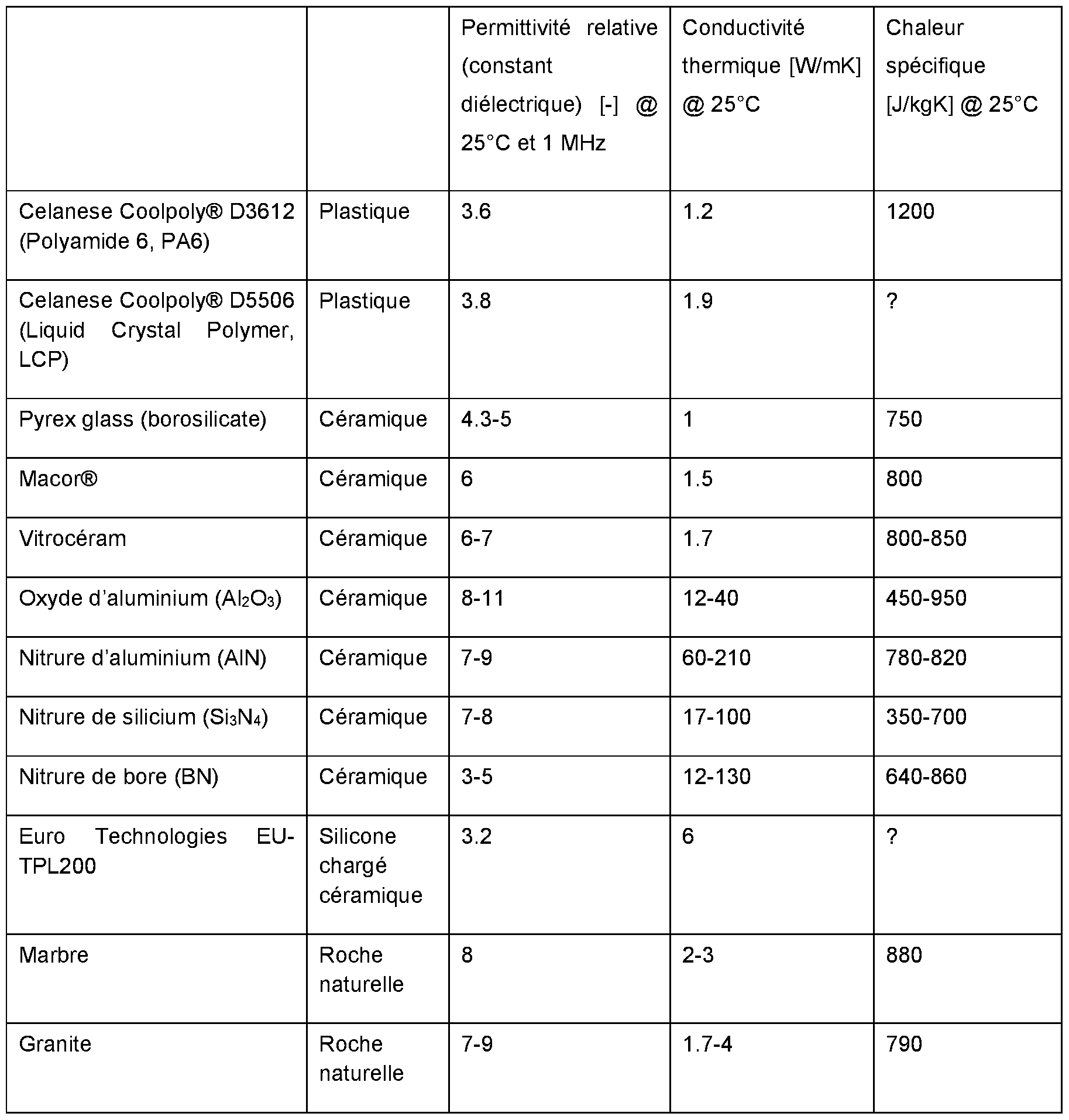
Table 2 : Liste de différents matériaux pouvant fonctionner comme isolant électrique et conducteur thermique. Table 2: List of different materials that can function as electrical insulator and thermal conductor.
Après avoir déterminé le(s) matériau(x) choisi(s) de cette couche isolante (par exemple dans le but de limiter le couplage capacitif), il est impératif de définir l’épaisseur de cette dernière. Si on
simplifie la modélisation du couplage à une seule couche en matière isolante d’une épaisseur dIS0 et d’une surface AIS0, la relation entre capacité de couplage et épaisseur s’exprime avec la formule du condensateur idéal :
 After having determined the material (s) chosen (s) of this insulating layer (for example in order to limit the capacitive coupling), it is imperative to define the thickness of the latter. If we simplifies the modeling of the coupling to a single layer of insulating material with a thickness d IS0 and a surface A IS0 , the relationship between coupling capacitance and thickness is expressed with the formula of the ideal capacitor:
La permittivité du vide e0 est une constante physique universelle, tandis que la permittivité relative (constante diélectrique) k dépend uniquement de la matière isolante choisie. The permittivity of vacuum e 0 is a universal physical constant, while the relative permittivity (dielectric constant) k depends only on the chosen insulating material.
De manière à simplifier la divulgation, le présent document donne comme exemple une matrice en silicone contenant des particules céramiques tel que le nitrure de bore, mais d’autres matériaux (notamment ceux qui sont listés dans ce document) peuvent permettre d’atteindre le même but avec un dimensionnement probablement différent. In order to simplify the disclosure, this document gives as an example a silicone matrix containing ceramic particles such as boron nitride, but other materials (especially those listed in this document) can make it possible to achieve the same. purpose with probably different sizing.

Table 3 : Liste des matériaux possibles de type matrice silicone chargé en particules Table 3: List of possible materials of the particle-loaded silicone matrix type
Dans notre exemple, la couche isolante comprend une matrice en silicone contenant des particules céramiques. Cette couche isolante peut avoir la forme d’un matelas souple. Ce matériau a un coefficient de transfert de chaleur élevé et isotrope, autour de 5 - 6.2W/mK pour les meilleurs, ainsi qu’une faible permittivité relative d’environ k - 3. Ce type de matériau peut ainsi être intéressant pour l’application dans un système de chauffage. L’application usuelle de ces matériaux est
d’ailleurs le transfert de chaleur d’un corps chaud tel qu’un composant électronique vers un radiateur. In our example, the insulating layer comprises a silicone matrix containing ceramic particles. This insulating layer may have the form of a flexible mattress. This material has a high and isotropic heat transfer coefficient, around 5 - 6.2W / mK for the best, as well as a low relative permittivity of around k - 3. This type of material can thus be interesting for the application in a heating system. The usual application of these materials is moreover the transfer of heat from a hot body such as an electronic component to a radiator.
En reprenant le tableau listant les capacités de couplage CCH nécessaires en fonction du couplage par la capacité CAC/DC dans l’alimentation, on obtient les épaisseurs suivantes pour k - 3 et AIS0 - 20x20 cm2 : Using the table listing the C CH coupling capacities required according to the coupling by the C AC / DC capacitor in the power supply, the following thicknesses are obtained for k - 3 and A IS0 - 20x20 cm 2 :

Pour des alimentations AC/DC réalistes avec un courant de fuite entre 20 et 30mA, il est donc nécessaire d’intercaler une couche isolante (de type silicone chargée en nitrure de bore) d’une épaisseur d’environ 5 à 7mm. Afin de ne pas freiner le transfert de chaleur, il est essentiel que le matériau isolant soit bon conducteur thermique. For realistic AC / DC power supplies with a leakage current between 20 and 30mA, it is therefore necessary to insert an insulating layer (silicone type loaded with boron nitride) with a thickness of about 5 to 7mm. In order not to slow down the heat transfer, it is essential that the insulating material is a good thermal conductor.
Réduction de la surface capacitive que la source de chaleur expose vers le chemin fluidique Reduction of the capacitive surface that the heat source exposes to the fluid path
La figure 6 schématise un système de chauffage où la source de chaleur (6) comprend des serpentins « classiques ». Ces serpentins classiques sont des bandes dont la largeur est agencée de manière parallèle à la plaque d’interface de manière à augmenter la surface de chauffe. Cette agencement parallèle peut être à l’origine du fort couplage capacitif et donc de la transmission de courants de fuite. En fait, les serpentins occupent une grande partie de la surface disponible dans la plaque de chauffe. L’avantage de ce montage est que le transfert de chaleur par conduction à travers la couche de plastique thermo-conducteur, mais électriquement isolant, est très direct et efficace.
Afin d’optimiser la surface métallique que les serpentins/bandes exposent vers le dialysat, une des solutions envisagées est de positionner la largeur des bandes de manière perpendiculaire au receveur (5) (par exemple en position verticale des bandes VS la position horizontal des bandes de la figure 6) comme le montre la figure 7. Par exemple, la largeur des bandes peut définir un plan perpendiculaire (Y ; Z) par rapport au plan (X ; Z) définit par la plaque d’interface (16) et/ou le receveur (5). Ainsi, la surface métallique exposée est fortement réduite, elle peut dépendre essentiellement de l’épaisseur des serpentins et non de leur largeur. Néanmoins, le transfert de chaleur par la couche (par exemple la plaque d’interface) est moins direct. FIG. 6 shows schematically a heating system where the heat source (6) comprises “conventional” coils. These conventional coils are bands whose width is arranged parallel to the interface plate so as to increase the heating surface. This parallel arrangement can be the source of the strong capacitive coupling and therefore of the transmission of leakage currents. In fact, the coils occupy a large part of the surface available in the heating plate. The advantage of this arrangement is that the heat transfer by conduction through the layer of thermally conductive, but electrically insulating, plastic is very direct and efficient. In order to optimize the metallic surface that the coils / bands expose towards the dialysate, one of the solutions considered is to position the width of the bands perpendicular to the receiver (5) (for example in the vertical position of the bands VS the horizontal position of the bands of figure 6) as shown in figure 7. For example, the width of the bands can define a perpendicular plane (Y; Z) with respect to the plane (X; Z) defined by the interface plate (16) and / or the receiver (5). Thus, the exposed metal surface is greatly reduced, it may depend essentially on the thickness of the coils and not on their width. However, the heat transfer through the layer (eg the interface plate) is less direct.
Cette position (verticale des serpentins) exposera uniquement l’épaisseur de l’élément chauffant, et non sa largeur, au liquide. Dans le cas où, les fils plats chauffants ont un ratio entre épaisseur et largeur qui dépasse 1 :10 (un à dix), la surface métallique exposée vers le dialysat sera réduite d’un facteur de 10 (dix) au moins. Cela se répercuterait directement sur le couplage capacitif et ainsi sur les courants de fuite. This position (vertical of the coils) will only expose the thickness of the heating element, not its width, to the liquid. In the event that the flat heating wires have a thickness-to-width ratio that exceeds 1:10 (one to ten), the exposed metal surface to the dialysate will be reduced by a factor of at least 10 (ten). This would have direct repercussions on the capacitive coupling and thus on the leakage currents.
Le système de chauffage devient nettement moins dépendant du choix de l’alimentation, pouvant éventuellement se contenter d’une alimentation de type BF sans pour autant compromettre le niveau de courants de fuite CF exigé pour l’appareil médical dans sa globalité (en particulier pour la partie appliquée). The heating system becomes much less dependent on the choice of power supply, possibly being able to be satisfied with a type BF power supply without compromising the level of CF leakage currents required for the medical device as a whole (in particular for the applied part).
Un système de plaque chauffante avec serpentins résistifs peut être maintenu. Afin de réaliser un contrôle de la température en boucle fermée (via le dispositif électronique de gestion), des capteurs de température peuvent être placés dans la plaque d’interface. A heating plate system with resistive coils can be maintained. In order to achieve closed-loop temperature control (via the electronic management device), temperature sensors can be placed in the interface plate.
Bien que le transfert de chaleur vers le dialysat soit moins direct que dans la solution classique, de nouveaux matériaux plastiques et composites (par exemple des plastiques chargés en particules métalliques ou céramiques) permettent aujourd’hui une très bonne conduction thermique, en étant des isolateurs électriques en même temps. La finesse du matériau isolant que l’on recherche permettra de travailler avec un faible gradient de température. Ceci équivaut à un besoin moindre en termes d’isolation entre la source de chauffe et le reste de la machine. En outre, l’encombrement d’une solution avec transfert de chaleur par conduction est moindre comparé à une solution avec transfert par radiation ou par convection, ou toute autre solution qui vise une réduction du niveau des courants de fuite par éloignement de la source de chaleur du dialysat. Although the heat transfer to the dialysate is less direct than in the conventional solution, new plastic and composite materials (for example plastics loaded with metallic or ceramic particles) today allow very good thermal conduction, being insulators. electric at the same time. The fineness of the insulating material that we are looking for will allow working with a low temperature gradient. This equates to less need for insulation between the heat source and the rest of the machine. In addition, the size of a solution with heat transfer by conduction is less compared to a solution with transfer by radiation or by convection, or any other solution which aims to reduce the level of leakage currents by moving away from the source of heat. heat of the dialysate.
Le système de plaque de chauffe esquissée dans la figure 7 peut comprendre une pièce plastique (qui peut être la plaque d’interface) avec les rainures pour les serpentins chauffants. Pour la pièce plastique, il est important de sélectionner un matériau qui soit thermiquement conducteur (conductivité thermique k>1W/mK), mais électriquement isolant. Les rainures pour les serpentins résistifs devront avoir une largeur de quelques dixièmes de millimètres, tandis que la profondeur sera de quelques millimètres. La pièce plastique peut être fabriquée via un processus d’injection ou tout autre processus de fabrication connu par l’homme du métier.
Exemple de mode de réalisation The heating plate system sketched in Figure 7 may include a plastic part (which may be the interface plate) with the grooves for the heating coils. For the plastic part, it is important to select a material which is thermally conductive (thermal conductivity k> 1W / mK), but electrically insulating. The grooves for the resistive coils should be a few tenths of a millimeter wide, while the depth will be a few millimeters. The plastic part can be manufactured via an injection process or any other manufacturing process known to those skilled in the art. Example of embodiment
Selon certains modes de réalisation comme divulgué par la figure 8, le système de chauffage (101) comprend une source de chaleur (108) et une interface comprenant une couche isolante (109) configurée pour limiter le couplage électrique (notamment capacitif) entre la source de chaleur (108) et le fluide à chauffer (non représenté ici) afin de limiter le courant de fuite du système à moins de 10 mA. According to certain embodiments as disclosed by FIG. 8, the heating system (101) comprises a heat source (108) and an interface comprising an insulating layer (109) configured to limit the electrical coupling (in particular capacitive) between the source (108) and the fluid to be heated (not shown here) to limit the system leakage current to less than 10 mA.
Préférentiellement, le système comprend une ou plusieurs couches empilées. En outre, l’interface peut comprendre au moins une des couches supplémentaires suivantes : Preferably, the system comprises one or more stacked layers. In addition, the interface may include at least one of the following additional layers:
une première couche de transmission de chaleur (110) ; et/ou a first heat transmitting layer (110); and or
une seconde couche de transmission de chaleur (112). a second heat transmitting layer (112).
La première couche de transmission de chaleur (110) peut être configurée pour entrer en contact avec le receveur de fluide à chauffer (non représenté ici). Cette première couche de transmission de chaleur (110) peut comprendre une surface supérieure et une surface inférieure. La surface supérieure peut être destinée à être en contact avec le receveur de fluide à chauffer. La surface inférieure peut être destinée à être en contact avec la couche isolante (par exemple une surface supérieure de la couche isolante). La première couche de transmission de chaleur peut s’étendre sur tout ou partie de la couche isolante (préférentiellement sur la quasi-totalité). La première couche de transmission peut comprendre de l’aluminium, du cuivre, de l’or, du nitrure d’aluminium, du laiton, du fer, un matériau composite, un élastomère, ... La première couche de transmission de chaleur (112) peut être configurée pour diffuser de manière substantiellement homogène la chaleur reçue au receveur. The first heat transmitting layer (110) can be configured to contact the receiver of the fluid to be heated (not shown here). This first heat transmitting layer (110) may include an upper surface and a lower surface. The upper surface may be intended to be in contact with the receiver of the fluid to be heated. The lower surface may be intended to be in contact with the insulating layer (for example an upper surface of the insulating layer). The first heat transmission layer can extend over all or part of the insulating layer (preferably over almost all). The first transmission layer can include aluminum, copper, gold, aluminum nitride, brass, iron, a composite material, an elastomer, ... The first heat transmission layer ( 112) can be configured to distribute the heat received substantially evenly to the receiver.
La seconde couche de transmission de chaleur (112) peut être configurée pour entrer en contact avec la source de chaleur (108). Cette seconde couche de transmission de chaleur (112) peut comprendre une surface supérieure et une surface inférieure. La surface supérieure peut être destinée à être en contact avec la couche isolante (109). La surface inférieure peut être destinée à être en contact avec la source de chaleur. La seconde couche de transmission de chaleur peut s’étendre sur tout ou partie de la couche isolante et/ou de la source de chaleur (préférentiellement sur la quasi-totalité d’au moins une des deux).. La seconde couche de transmission peut comprendre de l’aluminium, du cuivre, de l’or, du nitrure d’aluminium, du laiton, du fer, un matériau composite, un élastomère,... La seconde couche de transmission de chaleur (112) peut être configurée pour diffuser de manière substantiellement homogène la chaleur provenant de la source de chaleur à la couche isolante. The second heat transmitting layer (112) can be configured to contact the heat source (108). This second heat transmitting layer (112) can include an upper surface and a lower surface. The upper surface may be intended to be in contact with the insulating layer (109). The lower surface may be intended to be in contact with the heat source. The second heat transmission layer can extend over all or part of the insulating layer and / or of the heat source (preferably over almost all of at least one of the two). The second transmission layer can include aluminum, copper, gold, aluminum nitride, brass, iron, composite material, elastomer, ... The second heat transmitting layer (112) can be configured to diffusing heat from the heat source substantially evenly to the insulating layer.
Selon certains modes de réalisation, l’interface est configurée pour qu’il n’y ait pas d’espace vide ou de lame d’air entre les différentes couches de l’interface. Pour ce faire, l’interface peut comprendre des moyens (dispositifs) de fixation (115) permettant de maintenir solidaire ces couches entre elles. Ces couches peuvent être assemblées/fixées entre elles par vissage, collage, soudage, emboutissage, frettage, ... Préférentiellement, ces moyens de fixation sont configurés pour ne pas favoriser un couplage
électrique et ils peuvent être faits à partir de matériaux isolant électriquement, par exemple en plastique (vis en plastique,...). According to some embodiments, the interface is configured so that there is no empty space or air space between the different layers of the interface. To do this, the interface may comprise fixing means (devices) (115) making it possible to keep these layers integral with each other. These layers can be assembled / fixed together by screwing, gluing, welding, stamping, shrinking, etc. Preferably, these fixing means are configured so as not to promote coupling. electrical and they can be made from electrically insulating materials, for example plastic (plastic screws, ...).
Le système peut en outre comprendre un bac de réception configuré pour recevoir le receveur de fluide à chauffer. Ce bac de réception peut comprendre des parois rigides (111). La première couche de transmission de chaleur (110) peut former le fond de ce bac de réception. Dans ce cas, l’interface (du moins la première couche de transmission de chaleur (110)) est fixée de manière solidaire aux parois rigides (11 1) pour former le bac de réception. The system may further include a receiving pan configured to receive the fluid receiver to be heated. This receiving tray can include rigid walls (111). The first heat transmitting layer (110) can form the bottom of this receiving pan. In this case, the interface (at least the first heat transmission layer (110)) is integrally attached to the rigid walls (11 1) to form the receiving tray.
Le receveur de fluide à chauffer (non représenté ici) peut être une poche, un sac, un conteneur comprenant un compartiment à l’intérieurduquel le fluide à chauffer est chauffé. Le receveur peut comprendre une paroi flexible faite par exemple à base de matériau plastique ou autre dérivé. Le receveur peut comprendre une surface (par exemple une surface inférieure) destiné à être en contact avec une surface de l’interface (par exemple une surface supérieure). The receiver of the fluid to be heated (not shown here) can be a pocket, a bag, a container comprising a compartment inside which the fluid to be heated is heated. The receiver can comprise a flexible wall made for example based on plastic material or other derivative. The receiver may include a surface (eg, a bottom surface) for contacting a surface of the interface (eg, a top surface).
Selon certains modes de réalisation, le système de chauffage comprend une couche thermiquement isolante (107) configurée pour éviter une dissipation de la chaleur à des endroits non souhaités et éviter que la source de chaleur ne réchauffe l’intérieur du système, ce qui serait une perte d’énergie et pourrait provoquer un vieillissement prématuré des autres éléments du système tels que l’alimentation, le convertisseur, le dispositif de contrôle,... In some embodiments, the heating system includes a thermally insulating layer (107) configured to prevent heat dissipation to unwanted locations and prevent the heat source from heating up the interior of the system, which would be a disadvantage. loss of energy and could cause premature aging of other elements of the system such as the power supply, the converter, the control device, ...
Selon certains modes de réalisation, une plaque de support (106) permet de maintenir l’ensemble de différents éléments/couches (notamment l’interface et la source de chaleur) assemblés sans espace ni lame d’air entre (ces éléments ou couches) via par exemple des moyens de fixation (114) pouvant être comme ceux décrit ci-avant. La plaque de support est configurée pour apporter une certaine résistance mécanique de l’ensemble qui peut peser avec le receveur entre 2 et 8 kg. According to some embodiments, a support plate (106) keeps the set of different elements / layers (in particular the interface and the heat source) assembled without space or air space between (these elements or layers) via, for example, fixing means (114) which may be like those described above. The support plate is configured to provide a certain mechanical resistance to the assembly which can weigh with the receiver between 2 and 8 kg.
Selon certains modes de réalisation, le système de chauffage comprend en outre un moyen de pesage (102) fixé à l’ensemble (source de chaleur et interface) par exemple à la plaque de support (106). According to some embodiments, the heating system further comprises weighing means (102) attached to the assembly (heat source and interface), for example to the support plate (106).
La figure 9 divulgue l’assemblage et le détail Z. Selon certains modes de réalisation, le système peut comprendre un capteur de température. Ce capteur de température peut être agencé dans la cavité (118) ou dans la source de chaleur (108). Dans ce dernier cas, un moyen de transfert de chaleur (113) peut être agencé entre la couche de transmission (110) et le capteur de température de manière à ce que la température du receveur soit transmise au capteur de température. En fonction des besoins (contrainte dimensionnelle ou en fonction de la disposition des éléments), les couches de l’interface peuvent comprendre des ouvertures, préférentiellement à des endroits où il n’y a pas de serpentins résistifs de la source de chaleur afin d’éviter tous couplages électriques.
Combinaison(s) Figure 9 discloses the assembly and detail Z. In some embodiments, the system may include a temperature sensor. This temperature sensor can be arranged in the cavity (118) or in the heat source (108). In the latter case, a heat transfer means (113) may be arranged between the transmission layer (110) and the temperature sensor so that the temperature of the receiver is transmitted to the temperature sensor. Depending on the requirements (dimensional constraint or depending on the arrangement of the elements), the layers of the interface can include openings, preferably at places where there are no resistive coils of the heat source in order to avoid all electrical couplings. Combination (s)
Selon certains modes de réalisation, le système de chauffage comprend une ou plusieurs solutions citées ci-dessus. According to certain embodiments, the heating system comprises one or more solutions mentioned above.
Le système de chauffage peut être alimenté par une alimentation de type BF et comprend au moins une des solutions cité ci-dessus. L’alimentation peut être configurée pour induire ou induisant des courants de fuite compris entre 100 et 1 mA, préférentiellement entre 70 et 10 pA, plus préférentiellement entre 50 et 10 pA et encore plus préférentiellement entre 30 et 10 pA alors que le système de chauffage dans sa globalité peut ainsi induire un courant de fuite inférieur ou égal à 10 pA. The heating system can be supplied by a type BF power supply and comprises at least one of the solutions mentioned above. The power supply can be configured to induce or induce leakage currents of between 100 and 1 mA, preferably between 70 and 10 pA, more preferably between 50 and 10 pA and even more preferably between 30 and 10 pA while the heating system as a whole can thus induce a leakage current less than or equal to 10 pA.
Il s’agit ici de simples exemples de combinaison. D’autre combinaison sont possibles basées sur tout ou partie des solutions décrites dans ce document. These are simple examples of combinations. Other combinations are possible based on some or all of the solutions described in this document.
Exemple d’une construction classique 1 : Example of a classic construction 1:
Un appareil médical comprenant : A medical device comprising:
une alimentation de type BF classe II ayant un courant de fuite d’environ 70 pA comprenant un convertisseur isolé AC/DC, a type BF class II power supply with a leakage current of approximately 70 pA including an isolated AC / DC converter,
un élément chauffant dont les serpentins/bandes sont disposés de manière classique (horizontalement) (tel que la figure 2 ou 6) a heating element whose coils / bands are arranged in a conventional manner (horizontally) (such as figure 2 or 6)
Le courant de fuite mesuré à la partie appliquée est de 17 pA The leakage current measured at the applied part is 17 pA
Exemple d’une construction classique 2 : Example of a classic construction 2:
Un appareil médical comprenant : A medical device comprising:
une alimentation de type BF classe II ayant un courant de fuite d’environ 35 pA comprenant un convertisseur isolé AC/DC, a type BF class II power supply with a leakage current of approximately 35 pA including an isolated AC / DC converter,
un élément chauffant dont les serpentins/bandes sont disposés de manière classique (horizontalement) (tel que la figure 2 ou 6) a heating element whose coils / bands are arranged in a conventional manner (horizontally) (such as figure 2 or 6)
Le courant de fuite mesuré à la partie appliquée est de 14 pA The leakage current measured at the applied part is 14 pA
Exemple d’une construction classique 3 :
Un appareil médical comprenant : Example of a classic construction 3: A medical device comprising:
une alimentation de type BF classe II ayant un courant de fuite d’environ 70 mA comprenant un convertisseur isolé AC/AC, a type BF class II power supply with a leakage current of approximately 70 mA including an isolated AC / AC converter,
un élément chauffant dont les serpentins/bandes sont disposés de manière classique (horizontalement) (tel que la figure 2 ou 6) a heating element whose coils / bands are arranged in a conventional manner (horizontally) (such as figure 2 or 6)
Le courant de fuite mesuré à la partie appliquée est de 25 pA The leakage current measured at the applied part is 25 pA
Exemple d’une première combinaison : Example of a first combination:
Un appareil médical comprenant : A medical device comprising:
une alimentation de type BF classe II ayant un courant de fuite d’environ 70 pA comprenant un convertisseur isolé AC/DC, a type BF class II power supply with a leakage current of approximately 70 pA including an isolated AC / DC converter,
un élément chauffant dont les serpentins/bandes sont disposés de manière classique (horizontalement) (tel que la figure 2 ou 6) a heating element whose coils / bands are arranged in a conventional manner (horizontally) (such as figure 2 or 6)
une plaque d’interface comprenant un matériau composite tel qu’une matrice silicone chargée en particules de céramique (ou autre matériau ayant des caractéristiques isolantes similaires comme divulgué dans le présent document). an interface plate comprising a composite material such as a silicone matrix loaded with ceramic particles (or other material having similar insulating characteristics as disclosed in this document).
Le courant de fuite mesuré à la partie appliquée est inférieur à 10 pA The leakage current measured at the applied part is less than 10 pA
Exemple d’une deuxième combinaison : Example of a second combination:
Un appareil médical comprenant : A medical device comprising:
une alimentation de type BF classe II ayant un courant de fuite d’environ 70 pA comprenant un convertisseur isolé AC/DC, a type BF class II power supply with a leakage current of approximately 70 pA including an isolated AC / DC converter,
un élément chauffant dont les serpentins/bandes sont disposés de manière verticale (tel que la figure 7) a heating element with coils / bands arranged vertically (such as figure 7)
Le courant de fuite mesuré à la partie appliquée est inférieur à 10 pA. The leakage current measured at the applied part is less than 10 pA.
Exemple d’une troisième combinaison : Example of a third combination:
Un appareil médical comprenant : A medical device comprising:
une alimentation de type BF classe II ayant un courant de fuite d’environ 70 pA comprenant un convertisseur isolé AC/DC,
un élément chauffant dont les serpentins/bandes sont disposés de manière verticale (tel que la figure 7) a type BF class II power supply with a leakage current of approximately 70 pA comprising an isolated AC / DC converter, a heating element with coils / bands arranged vertically (such as figure 7)
une plaque d’interface comprenant un matériau composite tel qu’une matrice silicone chargée en particules de céramique (ou autre matériau ayant des caractéristiques isolantes similaires comme divulgué dans le présent document). an interface plate comprising a composite material such as a silicone matrix loaded with ceramic particles (or other material having similar insulating characteristics as disclosed in this document).
Le courant de fuite mesuré à la partie appliquée est inférieur à 10 pA. The leakage current measured at the applied part is less than 10 pA.
Exemple d’une quatrième combinaison : Example of a fourth combination:
Un appareil médical comprenant : A medical device comprising:
une alimentation de type BF classe II ayant un courant de fuite d’environ 30 mA comprenant un convertisseur isolé AC/DC, a type BF class II power supply with a leakage current of approximately 30 mA including an isolated AC / DC converter,
un élément chauffant dont les serpentins/bandes sont disposés de manière classique (horizontalement) (tel que la figure 2 ou 6) a heating element whose coils / bands are arranged in a conventional manner (horizontally) (such as figure 2 or 6)
une plaque d’interface comprenant un matériau composite tel qu’une matrice silicone chargée en particules de céramique (ou autre matériau ayant des caractéristiques isolantes similaires comme divulgué dans le présent document). an interface plate comprising a composite material such as a silicone matrix loaded with ceramic particles (or other material having similar insulating characteristics as disclosed in this document).
Le courant de fuite mesuré à la partie appliquée est inférieur à 10 pA The leakage current measured at the applied part is less than 10 pA
Exemple d’une cinquième combinaison : Example of a fifth combination:
Un appareil médical comprenant : A medical device comprising:
une alimentation de type BF classe II ayant un courant de fuite d’environ 30 pA comprenant un convertisseur isolé AC/DC, a type BF class II power supply with a leakage current of approximately 30 pA including an isolated AC / DC converter,
un élément chauffant dont les serpentins/bandes sont disposés de manière verticale (tel que la figure 7) a heating element with coils / bands arranged vertically (such as figure 7)
Le courant de fuite mesuré à la partie appliquée est inférieur à 10 pA. The leakage current measured at the applied part is less than 10 pA.
Exemple d’une sixième combinaison : Example of a sixth combination:
Un appareil médical comprenant : A medical device comprising:
une alimentation de type BF classe II ayant un courant de fuite d’environ 30 pA comprenant un convertisseur isolé AC/DC, a type BF class II power supply with a leakage current of approximately 30 pA including an isolated AC / DC converter,
un élément chauffant dont les serpentins/bandes sont disposés de manière verticale (tel que la figure 7)
une plaque d’interface comprenant un matériau composite tel qu’une matrice silicone chargée en particules de céramique (ou autre matériau ayant des caractéristiques isolantes similaires comme divulgué dans le présent document). a heating element with coils / bands arranged vertically (such as figure 7) an interface plate comprising a composite material such as a silicone matrix loaded with ceramic particles (or other material having similar insulating characteristics as disclosed in this document).
Le courant de fuite mesuré à la partie appliquée est inférieur à 10 pA. The leakage current measured at the applied part is less than 10 pA.
Exemple d’une septième combinaison : Example of a seventh combination:
Un appareil médical comprenant : A medical device comprising:
une alimentation de type BF classe II ayant un courant de fuite d’environ 70 mA comprenant un convertisseur isolé AC/AC, a type BF class II power supply with a leakage current of approximately 70 mA including an isolated AC / AC converter,
un élément chauffant dont les serpentins/bandes sont disposés de manière classique (horizontalement) (tel que la figure 2 ou 6) a heating element whose coils / bands are arranged in a conventional manner (horizontally) (such as figure 2 or 6)
une plaque d’interface comprenant un blindage comme divulgué dans ce document. an interface plate including shielding as disclosed in this document.
Le courant de fuite mesuré à la partie appliquée est inférieur à 10 pA The leakage current measured at the applied part is less than 10 pA
Exemple d’une huitième combinaison : Example of an eighth combination:
Un appareil médical comprenant : A medical device comprising:
une alimentation de type BF classe II ayant un courant de fuite d’environ 70 pA comprenant un convertisseur isolé AC/AC, a type BF class II power supply with a leakage current of approximately 70 pA including an isolated AC / AC converter,
un élément chauffant dont les serpentins/bandes sont disposés de manière classique (horizontalement) (tel que la figure 2 ou 6) a heating element whose coils / bands are arranged in a conventional manner (horizontally) (such as figure 2 or 6)
une plaque d’interface comprenant un blindage configuré pour limiter le couplage capacitif comme divulgué dans ce document. an interface plate comprising a shield configured to limit capacitive coupling as disclosed in this document.
Le courant de fuite mesuré à la partie appliquée est inférieur à 10 pA. The leakage current measured at the applied part is less than 10 pA.
Exemple d’une neuvième combinaison : Example of a ninth combination:
Un appareil médical comprenant : A medical device comprising:
une alimentation de type BF classe II ayant un courant de fuite d’environ 70 pA comprenant un convertisseur isolé AC/AC, a type BF class II power supply with a leakage current of approximately 70 pA including an isolated AC / AC converter,
un élément chauffant dont les serpentins/bandes sont disposés de manière verticale (tel que la figure 7) a heating element with coils / bands arranged vertically (such as figure 7)
une plaque d’interface comprenant un blindage configuré pour limiter le couplage électrique (par exemple capacitif) comme divulgué dans ce document.
Le courant de fuite mesuré à la partie appliquée est inférieur à 10 mA.
an interface plate comprising a shield configured to limit electrical coupling (eg capacitive) as disclosed in this document. The leakage current measured at the applied part is less than 10 mA.
Claims
1. Système de chauffage configuré pour chauffer un fluide en communication électrique avec un patient, le système comprenant : A heating system configured to heat a fluid in electrical communication with a patient, the system comprising:
• Une alimentation électrique non reliée à la terre induisant un courant de fuite supérieur à 10mA, • An unearthed power supply inducing a leakage current greater than 10mA,
• Une source de chaleur alimentée par l’alimentation électrique et • A heat source supplied by the power supply and
• Une couche isolante disposée entre la source de chaleur et le fluide à chauffer ; • An insulating layer placed between the heat source and the fluid to be heated;
Dans lequel la couche isolante comprend un matériau électriquement isolant et Wherein the insulating layer comprises an electrically insulating material and
Dans lequel la couche isolante est dimensionnée de manière à ce que le courant de fuite du système transmis au fluide à chauffer soit inférieur ou égal à 10mA tout en permettant une transmission optimale de chaleur de la source de chaleur au fluide à chauffer. In which the insulating layer is dimensioned so that the leakage current of the system transmitted to the fluid to be heated is less than or equal to 10mA while allowing optimal transmission of heat from the heat source to the fluid to be heated.
2. Système selon la revendication 1 , dans lequel l’épaisseur de la couche isolante est substantiellement égale ou inférieur à 10mm. 2. System according to claim 1, wherein the thickness of the insulating layer is substantially equal to or less than 10mm.
3. Système selon l’une des précédentes revendications, dans lequel la couche isolante est caractérisée par une conductivité thermique isotrope. 3. System according to one of the preceding claims, wherein the insulating layer is characterized by isotropic thermal conductivity.
4. Système selon l’une des précédentes revendications, dans lequel la source de chaleur comprend des serpentins résistifs et dans lequel la couche isolante recouvre les serpentins résistifs. 4. System according to one of the preceding claims, in which the heat source comprises resistive coils and in which the insulating layer covers the resistive coils.
5. Système selon l’une des précédentes revendications, dans lequel la couche isolante recouvre intégralement la source de chaleur. 5. System according to one of the preceding claims, wherein the insulating layer completely covers the heat source.
6. Système selon l’une des précédentes revendications, dans lequel la couche isolante caractérisé par une haute conductivité thermique, une haute résistance électrique et une faible constante diélectrique.
6. System according to one of the preceding claims, wherein the insulating layer characterized by high thermal conductivity, high electrical resistance and low dielectric constant.
7. Système selon l’une des précédentes revendications, dans lequel la capacité thermique massique de la couche isolante est substantiellement égale ou inférieure à 1400 J. Kg·1. K 1 , préférentiellement substantiellement égale ou inférieure à 1200 J. Kg 1. K 1 , plus préférentiellement substantiellement égale ou inférieure à 1100 J. Kg·1. K 1. 7. System according to one of the preceding claims, wherein the specific heat capacity of the insulating layer is substantially equal to or less than 1400 J. Kg · 1 . K 1 , preferably substantially equal to or less than 1200 J. Kg 1 . K 1 , more preferably substantially equal to or less than 1100 J. Kg · 1 . K 1 .
8. Système selon l’une des précédentes revendications, dans lequel la conductivité thermique de la couche isolante est substantiellement égale ou supérieure à 4 W.rrr1K·1, préférentiellement égale ou supérieure à 5 W.nr1K 1 , plus préférentiellement égale ou supérieur à 5 W.nr1K 1 8. System according to one of the preceding claims, wherein the thermal conductivity of the insulating layer is substantially equal to or greater than 4 W.rrr 1 K · 1 , preferably equal to or greater than 5 W.nr 1 K 1 , more preferably. equal to or greater than 5 W.nr 1 K 1
9. Système selon l’une des précédentes revendications, dans lequel la constante diélectrique de la couche isolante est substantiellement égale ou inférieure à 5, préférentiellement égale ou inférieure à 4, plus préférentiellement égale ou inférieure à 3. 9. System according to one of the preceding claims, in which the dielectric constant of the insulating layer is substantially equal to or less than 5, preferably equal to or less than 4, more preferably equal to or less than 3.
10. Système selon l’une des précédentes revendications, dans lequel la couche isolante comprend un élastomère de silicone. 10. System according to one of the preceding claims, wherein the insulating layer comprises a silicone elastomer.
11 . Système selon l’une des précédentes revendications, dans lequel la couche isolante comprend du nitrure de bore. 11. System according to one of the preceding claims, wherein the insulating layer comprises boron nitride.
12. Système selon l’une des précédentes revendications, dans lequel la couche isolante comprend un élastomère de silicone chargé en céramique. 12. System according to one of the preceding claims, wherein the insulating layer comprises a silicone elastomer loaded with ceramic.
13. Système selon la revendication précédente, dans lequel la céramique comprend du nitrure de bore. 13. System according to the preceding claim, in which the ceramic comprises boron nitride.
14. Système selon l’une des précédentes revendications comprenant en outre une première couche de transmission de la chaleur comprenant un matériau conducteur de chaleur configuré pour transmettre la chaleur de la source de chaleur au fluide à chauffer. 14. System according to one of the preceding claims further comprising a first heat transmitting layer comprising a heat conductive material configured to transmit heat from the heat source to the fluid to be heated.
15. Système selon la revendication précédente, dans lequel la couche isolante est disposée entre la source de chaleur et la première couche de transmission de la chaleur.
15. System according to the preceding claim, wherein the insulating layer is disposed between the heat source and the first heat transmission layer.
16. Système selon l’une des précédentes revendications comprenant une seconde couche de transmission de la chaleur comprenant un matériau conducteur de chaleur configuré pour transmettre la chaleur de la source de chaleur au fluide à chauffer. 16. System according to one of the preceding claims comprising a second heat transmitting layer comprising a heat conductive material configured to transmit heat from the heat source to the fluid to be heated.
17. Système selon la revendication précédente, dans lequel la seconde couche de transmission de la chaleur est disposée entre la source de chaleur et la couche isolante. 17. System according to the preceding claim, wherein the second heat transmitting layer is arranged between the heat source and the insulating layer.
18. Système selon l’une des précédentes revendications, dans lequel l’alimentation électrique comprend un convertisseur AC/DC. 18. System according to one of the preceding claims, wherein the power supply comprises an AC / DC converter.
19. Système selon l’une des précédentes revendications, dans lequel l’alimentation électrique est configuré pour fonctionner avec un réseau d’alimentation externe fournissant une tension comprise entre 85VAC et 260VAC. 19. System according to one of the preceding claims, in which the power supply is configured to operate with an external power supply network providing a voltage between 85VAC and 260VAC.
20. Système selon l’une des précédentes revendications comprenant une partie appliquée en communication fluidique avec le fluide à chauffer et destinée à être en contact avec le patient, 20. System according to one of the preceding claims comprising a part applied in fluid communication with the fluid to be heated and intended to be in contact with the patient,
21 . Système selon l’une des précédentes revendications, dans lequel la couche isolante comprend un matériau isolant adapté pour limiter un couplage électrique entre la source de chaleur et le fluide à chauffer de manière à ce que le courant de fuite du système transmis au fluide à chauffer soit inférieur ou égal à 10mA. 21. System according to one of the preceding claims, in which the insulating layer comprises an insulating material adapted to limit an electrical coupling between the heat source and the fluid to be heated so that the leakage current of the system transmitted to the fluid to be heated or less than or equal to 10mA.
22. Système selon l’une des précédentes revendications, dans lequel la couche isolante comprend un matériau isolant adapté pour limiter un couplage capacitif entre la source de chaleur et le fluide à chauffer de manière à ce que le courant de fuite du système transmis au fluide à chauffer soit inférieur ou égal à 10mA. 22. System according to one of the preceding claims, wherein the insulating layer comprises an insulating material suitable for limiting capacitive coupling between the heat source and the fluid to be heated so that the leakage current of the system transmitted to the fluid. to be heated either less than or equal to 10mA.
23. Un System de chauffage d’un fluide induisant un courant de fuite patient inférieur à 10mA, le système comprenant : 23. A system for heating a fluid inducing a patient leakage current of less than 10mA, the system comprising:
• Un receveur destiné à contenir un fluide à chauffer, • A receiver intended to contain a fluid to be heated,
• Une alimentation électrique non reliée à la terre et alimentée par une source électrique externe,
• Une source de chauffage alimentée par l’alimentation électrique configurée pour chauffer le fluide présent dans le receveur et • An unearthed power supply supplied by an external power source, • A heating source supplied by the power supply configured to heat the fluid present in the receiver and
• Une interface agencée entre la source de chauffage et le receveur configurée pour transmettre la chaleur de la source de chaleur au fluide à chauffer ; • An interface arranged between the heating source and the receiver configured to transmit heat from the heat source to the fluid to be heated;
Dans lequel l’interface comprend une couche isolante incluant un matériau isolant configuré pour limiter un couplage électrique (sans contact) entre la source de chauffage et le receveur de manière à ce que le système de chauffage ne puisse induire un courant de fuite patient supérieur à 10mA. In which the interface comprises an insulating layer including an insulating material configured to limit electrical (non-contact) coupling between the heating source and the receiver so that the heating system cannot induce a patient leakage current greater than 10mA.
24. Système selon la précédente revendication, dans lequel la couche isolante et la source de chaleur sont disposées en matelas superposés où la couche isolante est pris en sandwich entre la source de chaleur et le fluide à chauffer. 24. System according to the preceding claim, in which the insulating layer and the heat source are arranged in superimposed mattresses where the insulating layer is sandwiched between the heat source and the fluid to be heated.
25. Système selon l’une des précédentes revendications 23 à 24, dans lequel la couche isolante comprend une haute conductivité thermique, une haute résistance électrique et une faible constante diélectrique. 25. System according to one of the preceding claims 23 to 24, in which the insulating layer comprises high thermal conductivity, high electrical resistance and low dielectric constant.
26. Système selon l’une des précédentes revendications 23 à 25, dans lequel la couche isolante comprend un élastomère de silicone, du nitrure de bore, un élastomère de silicone chargé en céramique, un élastomère de silicone chargé en céramique comprenant du nitrure de bore, du borosilicate, de la vitrocéramique, de l’oxyde d’aluminium, du nitrure d’aluminium, du nitrure de silicium, du nitrure de bore, des particules métalliques, des particules céramiques, du silicone chargé en particules métalliques ou céramiques. 26. System according to one of the preceding claims 23 to 25, wherein the insulating layer comprises a silicone elastomer, boron nitride, a ceramic filled silicone elastomer, a ceramic filled silicone elastomer comprising boron nitride. , borosilicate, glass-ceramic, aluminum oxide, aluminum nitride, silicon nitride, boron nitride, metal particles, ceramic particles, silicone loaded with metal or ceramic particles.
27. Système selon l’une des précédentes revendications 23 à 26, dans lequel l’interface comprend en outre une première couche de transmission de la chaleur comprenant un matériau conducteur de chaleur configuré pour transmettre la chaleur de la source de chaleur au fluide à chauffer. 27. System according to one of the preceding claims 23 to 26, wherein the interface further comprises a first heat transmitting layer comprising a heat conductive material configured to transmit heat from the heat source to the fluid to be heated. .
28. Système selon l’une des précédentes revendications 23 à 27, dans lequel l’interface comprend en outre une seconde couche de transmission de la chaleur comprenant un matériau conducteur de chaleur configuré pour transmettre la chaleur de la source de chaleur au fluide à chauffer. 28. System according to one of the preceding claims 23 to 27, wherein the interface further comprises a second heat transmitting layer comprising a heat conductive material configured to transmit heat from the heat source to the fluid to be heated. .
29. Système selon l’une des précédentes revendications 23 à 28, dans lequel l’alimentation électrique est configurée pour ne pas être reliée à la terre.
29. System according to one of the preceding claims 23 to 28, wherein the power supply is configured so as not to be earthed.
30. Système selon l’une des précédentes revendications 23 à 29, dans lequel l’alimentation électrique est configurée pour fonctionner avec une source électrique externe fournissant une tension comprise entre 85VAC et 260VAC. 30. System according to one of the preceding claims 23 to 29, wherein the power supply is configured to operate with an external power source providing a voltage between 85VAC and 260VAC.
31 . Système selon l’une des précédentes revendications 23 à 30 comprenant une partie appliquée en communication électrique avec le patient, 31. System according to one of the preceding claims 23 to 30 comprising an applied part in electrical communication with the patient,
32. Système selon l’une des précédentes revendications 23 à 31 , dans lequel le matériau isolant est adapté pour limiter un couplage capacitif entre la source de chaleur et le fluide à chauffer. 32. System according to one of the preceding claims 23 to 31, wherein the insulating material is adapted to limit capacitive coupling between the heat source and the fluid to be heated.
33. Système selon l’une des précédentes revendications 23 à 32, dans lequel l’alimentation électrique est de classe II. 33. System according to one of the preceding claims 23 to 32, in which the power supply is of class II.
34. Un système de chauffage pour fluide médicale comprenant : 34. A heating system for medical fluid comprising:
• un receveur de fluide médical à chauffer, • a receiver of medical fluid to be heated,
• une partie appliquée en communication fluidique avec le fluide médical et destinée à être en contact avec un patient, • a part applied in fluid communication with the medical fluid and intended to be in contact with a patient,
• une alimentation électrique induisant un courant de fuite compris entre 100 et 10 mA • a power supply inducing a leakage current of between 100 and 10 mA
• un élément chauffant destiné à chauffer le fluide médical et alimenté par l’alimentation électrique et • a heating element intended to heat the medical fluid and supplied by the power supply and
• une interface disposée entre l’élément chauffant et le fluide à chauffer contenu dans le receveur • an interface arranged between the heating element and the fluid to be heated contained in the receiver
Caractérisé en ce que l’élément chauffant et/ou l’interface sont adaptés pour limiter le couplage inductif et/ou capacitif de sorte que les courants de fuite des partie appliquées soient inférieur à 10 pA. Characterized in that the heating element and / or the interface are adapted to limit the inductive and / or capacitive coupling so that the leakage currents of the applied parts are less than 10 pA.
35. Système de chauffage selon la revendication 34, dans lequel l’élément chauffant comprend des bandes dont leurs largeurs sont disposées de manière verticale.
35. A heating system according to claim 34, wherein the heating element comprises strips whose widths are arranged vertically.
36. Système de chauffage selon la revendication 34, dans lequel l’élément chauffant comprend des bandes dont leurs largeurs sont disposées de manière horizontal. 36. A heating system according to claim 34, wherein the heating element comprises bands whose widths are arranged horizontally.
37. Système de chauffage selon l’une des précédentes revendications 34 à 36, dans lequel l’interface comprend un matériau composite. 37. A heating system according to one of the preceding claims 34 to 36, wherein the interface comprises a composite material.
38. Système de chauffage selon la revendication précédente, dans lequel le matériau composite comprend au moins des éléments suivants : du borosilicate, de la vitrocéramique, de l’oxyde d’aluminium, du nitrure d’aluminium, du nitrure de silicium, du nitrure de bore, des particules métalliques, des particules céramiques, du silicone chargé en particules métalliques ou céramiques. 38. Heating system according to the preceding claim, in which the composite material comprises at least of the following elements: borosilicate, glass-ceramic, aluminum oxide, aluminum nitride, silicon nitride, nitride boron, metallic particles, ceramic particles, silicone loaded with metallic or ceramic particles.
39. Système de chauffage selon la revendication 37, dans lequel le matériau composite est caractérisé par une faible permittivité diélectrique relative, une bonne conductivité thermique et une faible chaleur spécifique. 39. The heating system of claim 37, wherein the composite material is characterized by a low relative dielectric permittivity, good thermal conductivity and low specific heat.
40. Système de chauffage selon la revendication 37, dans lequel le matériau composite est caractérisé par une permittivité diélectrique relative substantiellement égale ou inférieure à 5, préférentiellement égale ou inférieure à 4, plus préférentiellement égale ou inférieure à 3. 40. Heating system according to claim 37, in which the composite material is characterized by a relative dielectric permittivity substantially equal to or less than 5, preferably equal to or less than 4, more preferably equal to or less than 3.
41 . Système de chauffage selon la revendication 37, dans lequel le matériau composite est caractérisé par une conductivité thermique supérieure ou substantiellement égale à 4 W/mK. 41. A heating system according to claim 37, wherein the composite material is characterized by a thermal conductivity greater than or substantially equal to 4 W / mK.
42. Système de chauffage selon l’une des précédentes revendications 34 à 41 , dans lequel l’interface comprend un dispositif de transfert de chaleur comprenant un fluide caloporteur. 42. Heating system according to one of the preceding claims 34 to 41, wherein the interface comprises a heat transfer device comprising a heat transfer fluid.
43. Système de chauffage selon l’une des précédentes revendications 34 à 42, dans lequel l’interface comprend un blindage magnétique. 43. A heating system according to one of the preceding claims 34 to 42, wherein the interface comprises a magnetic shield.
44. Système de chauffage selon l’une des précédentes revendications 34 à 43, dans lequel la partie appliquée est en contact avec le cœur, le myocarde ou une cavité contiguë au cœur d’un patient.
44. Heating system according to one of the preceding claims 34 to 43, wherein the applied part is in contact with the heart, the myocardium or a cavity contiguous to the heart of a patient.
45. Système de chauffage selon l’une des précédentes revendications 34 à 44, dans lequel l’alimentation électrique comprend un convertisseur isolé AC/AC ou AC/DC. 45. Heating system according to one of the preceding claims 34 to 44, wherein the power supply comprises an isolated AC / AC or AC / DC converter.
46. Système de chauffage selon l’une des précédentes revendications 34 à 45, dans lequel l’alimentation électrique n’est connectée à la terre. 46. Heating system according to one of the preceding claims 34 to 45, in which the power supply is not connected to earth.
47. Système de traitement de dialyse comprenant un système de chauffage selon l’une des précédentes revendications. 47. A dialysis treatment system comprising a heating system according to one of the preceding claims.
48. Système de traitement de dialyse selon la revendication 47, dans lequel le fluide à chauffer est du sang ou du dialysat. 48. The dialysis treatment system of claim 47, wherein the fluid to be heated is blood or dialysate.
49. Système de traitement de dialyse selon l’une des précédentes revendications 47 à 49, dans lequel la partie appliquée comprend un cathéter veineux central ou un cathéter veineux périphérique long.
49. The dialysis treatment system according to one of the preceding claims 47 to 49, wherein the applied part comprises a central venous catheter or a long peripheral venous catheter.
Priority Applications (2)
| Application Number | Priority Date | Filing Date | Title |
|---|---|---|---|
| US17/442,422 US20220184286A1 (en) | 2019-04-05 | 2020-04-01 | Heating System with Low Leakage Current |
| EP20723193.7A EP3946507A1 (en) | 2019-04-05 | 2020-04-01 | Heating system with low leakage current |
Applications Claiming Priority (6)
| Application Number | Priority Date | Filing Date | Title |
|---|---|---|---|
| EP19167705.3 | 2019-04-05 | ||
| EP19167705 | 2019-04-05 | ||
| EP19167988 | 2019-04-08 | ||
| EP19167988.5 | 2019-04-08 | ||
| EP19168278 | 2019-04-09 | ||
| EP19168278.0 | 2019-04-09 |
Publications (1)
| Publication Number | Publication Date |
|---|---|
| WO2020202022A1 true WO2020202022A1 (en) | 2020-10-08 |
Family
ID=70480307
Family Applications (1)
| Application Number | Title | Priority Date | Filing Date |
|---|---|---|---|
| PCT/IB2020/053088 WO2020202022A1 (en) | 2019-04-05 | 2020-04-01 | Heating system with low leakage current |
Country Status (3)
| Country | Link |
|---|---|
| US (1) | US20220184286A1 (en) |
| EP (1) | EP3946507A1 (en) |
| WO (1) | WO2020202022A1 (en) |
Citations (5)
| Publication number | Priority date | Publication date | Assignee | Title |
|---|---|---|---|---|
| US20030220598A1 (en) * | 2002-05-24 | 2003-11-27 | Don Busby | Automated dialysis system |
| WO2012155149A2 (en) * | 2011-05-12 | 2012-11-15 | Nxstage Medical, Inc. | Fluid heating apparatuses, systems, and methods |
| WO2015162593A1 (en) | 2014-04-25 | 2015-10-29 | Debiotech S.A. | Hemodialysis systems |
| US20170065758A1 (en) * | 2010-04-28 | 2017-03-09 | Watlow Electric Manufacturing Company | Flow through heater |
| WO2019087096A1 (en) | 2017-10-31 | 2019-05-09 | Debiotech S.A. | Easily movable blood purification systems |
-
2020
- 2020-04-01 US US17/442,422 patent/US20220184286A1/en active Pending
- 2020-04-01 WO PCT/IB2020/053088 patent/WO2020202022A1/en unknown
- 2020-04-01 EP EP20723193.7A patent/EP3946507A1/en active Pending
Patent Citations (6)
| Publication number | Priority date | Publication date | Assignee | Title |
|---|---|---|---|---|
| US20030220598A1 (en) * | 2002-05-24 | 2003-11-27 | Don Busby | Automated dialysis system |
| US20170065758A1 (en) * | 2010-04-28 | 2017-03-09 | Watlow Electric Manufacturing Company | Flow through heater |
| WO2012155149A2 (en) * | 2011-05-12 | 2012-11-15 | Nxstage Medical, Inc. | Fluid heating apparatuses, systems, and methods |
| WO2015162593A1 (en) | 2014-04-25 | 2015-10-29 | Debiotech S.A. | Hemodialysis systems |
| WO2019087096A1 (en) | 2017-10-31 | 2019-05-09 | Debiotech S.A. | Easily movable blood purification systems |
| WO2019087103A1 (en) | 2017-10-31 | 2019-05-09 | Debiotech S.A. | Automated extracorporeal blood treatment apparatus |
Also Published As
| Publication number | Publication date |
|---|---|
| EP3946507A1 (en) | 2022-02-09 |
| US20220184286A1 (en) | 2022-06-16 |
Similar Documents
| Publication | Publication Date | Title |
|---|---|---|
| US11641872B2 (en) | Aerosol-forming substrate and aerosol-delivery system | |
| US20230001115A1 (en) | Cartridge for e-vaping device with open-microchannels | |
| AU2015261876B2 (en) | Inductive heating device and system for aerosol generation | |
| EP2883006B1 (en) | Device for the induction heating of a water heater and water heater provided with such a device | |
| AU2019395786B2 (en) | Aerosol generating apparatus and method of operating same | |
| KR102649839B1 (en) | Induction heating assembly for a vapour generating device | |
| KR20190039713A (en) | Aerosol generator with inductor | |
| FR2748885A1 (en) | HIGH EFFICIENCY INDUCTION COOKING FIREPLACE | |
| CN109674095A (en) | Cigarette heater and electrically heated cigarette smoking device, heat-proof device | |
| WO2015018734A1 (en) | Water heater | |
| EP3946507A1 (en) | Heating system with low leakage current | |
| EP2523291A1 (en) | Branching element for a superconductor cable unit | |
| EP2883005A1 (en) | Assembly formed from a water heater comprising a heating body comprising a volume of water and at least one generator of an inductive module dedicated to an electrical appliance | |
| US8731384B2 (en) | Steam head for cleaner | |
| CA2285806C (en) | Dry-type distribution and power transformer | |
| CN208434140U (en) | A kind of electromagnetic heating liner and liquid heater | |
| WO2017108579A1 (en) | Hot-water storage multi-tank domestic water heater | |
| FR3111792A1 (en) | Implantable localized cooling probe | |
| CN104994770B (en) | Water heater container with fluid dispenser | |
| Chen et al. | Electric property of silicone rubber composite filled with nano-conductive fibre and conductive carbon-black | |
| TWM435578U (en) | Electric heater and instant water heater |
Legal Events
| Date | Code | Title | Description |
|---|---|---|---|
| 121 | Ep: the epo has been informed by wipo that ep was designated in this application |
Ref document number: 20723193 Country of ref document: EP Kind code of ref document: A1 |
|
| NENP | Non-entry into the national phase |
Ref country code: DE |
|
| ENP | Entry into the national phase |
Ref document number: 2020723193 Country of ref document: EP Effective date: 20211105 |