WO2020201004A1 - Acoustofluidic device - Google Patents

Acoustofluidic device Download PDF

Info

Publication number
WO2020201004A1
WO2020201004A1 PCT/EP2020/058531 EP2020058531W WO2020201004A1 WO 2020201004 A1 WO2020201004 A1 WO 2020201004A1 EP 2020058531 W EP2020058531 W EP 2020058531W WO 2020201004 A1 WO2020201004 A1 WO 2020201004A1
Authority
WO
WIPO (PCT)
Prior art keywords
channel
acoustic wave
transducer
saw
ssaw
Prior art date
Legal status (The legal status is an assumption and is not a legal conclusion. Google has not performed a legal analysis and makes no representation as to the accuracy of the status listed.)
Ceased
Application number
PCT/EP2020/058531
Other languages
French (fr)
Inventor
Xin Yang
Current Assignee (The listed assignees may be inaccurate. Google has not performed a legal analysis and makes no representation or warranty as to the accuracy of the list.)
University College Cardiff Consultants Ltd
Original Assignee
University College Cardiff Consultants Ltd
Priority date (The priority date is an assumption and is not a legal conclusion. Google has not performed a legal analysis and makes no representation as to the accuracy of the date listed.)
Filing date
Publication date
Application filed by University College Cardiff Consultants Ltd filed Critical University College Cardiff Consultants Ltd
Priority to GB2113171.9A priority Critical patent/GB2596444A/en
Priority to US17/599,703 priority patent/US20220193663A1/en
Publication of WO2020201004A1 publication Critical patent/WO2020201004A1/en
Anticipated expiration legal-status Critical
Ceased legal-status Critical Current

Links

Classifications

    • BPERFORMING OPERATIONS; TRANSPORTING
    • B01PHYSICAL OR CHEMICAL PROCESSES OR APPARATUS IN GENERAL
    • B01LCHEMICAL OR PHYSICAL LABORATORY APPARATUS FOR GENERAL USE
    • B01L3/00Containers or dishes for laboratory use, e.g. laboratory glassware; Droppers
    • B01L3/50Containers for the purpose of retaining a material to be analysed, e.g. test tubes
    • B01L3/502Containers for the purpose of retaining a material to be analysed, e.g. test tubes with fluid transport, e.g. in multi-compartment structures
    • B01L3/5027Containers for the purpose of retaining a material to be analysed, e.g. test tubes with fluid transport, e.g. in multi-compartment structures by integrated microfluidic structures, i.e. dimensions of channels and chambers are such that surface tension forces are important, e.g. lab-on-a-chip
    • B01L3/50273Containers for the purpose of retaining a material to be analysed, e.g. test tubes with fluid transport, e.g. in multi-compartment structures by integrated microfluidic structures, i.e. dimensions of channels and chambers are such that surface tension forces are important, e.g. lab-on-a-chip characterised by the means or forces applied to move the fluids
    • BPERFORMING OPERATIONS; TRANSPORTING
    • B01PHYSICAL OR CHEMICAL PROCESSES OR APPARATUS IN GENERAL
    • B01DSEPARATION
    • B01D21/00Separation of suspended solid particles from liquids by sedimentation
    • B01D21/28Mechanical auxiliary equipment for acceleration of sedimentation, e.g. by vibrators or the like
    • B01D21/283Settling tanks provided with vibrators
    • BPERFORMING OPERATIONS; TRANSPORTING
    • B06GENERATING OR TRANSMITTING MECHANICAL VIBRATIONS IN GENERAL
    • B06BMETHODS OR APPARATUS FOR GENERATING OR TRANSMITTING MECHANICAL VIBRATIONS OF INFRASONIC, SONIC, OR ULTRASONIC FREQUENCY, e.g. FOR PERFORMING MECHANICAL WORK IN GENERAL
    • B06B1/00Methods or apparatus for generating mechanical vibrations of infrasonic, sonic, or ultrasonic frequency
    • B06B1/02Methods or apparatus for generating mechanical vibrations of infrasonic, sonic, or ultrasonic frequency making use of electrical energy
    • B06B1/0207Driving circuits
    • B06B1/0223Driving circuits for generating signals continuous in time
    • B06B1/0238Driving circuits for generating signals continuous in time of a single frequency, e.g. a sine-wave
    • BPERFORMING OPERATIONS; TRANSPORTING
    • B06GENERATING OR TRANSMITTING MECHANICAL VIBRATIONS IN GENERAL
    • B06BMETHODS OR APPARATUS FOR GENERATING OR TRANSMITTING MECHANICAL VIBRATIONS OF INFRASONIC, SONIC, OR ULTRASONIC FREQUENCY, e.g. FOR PERFORMING MECHANICAL WORK IN GENERAL
    • B06B1/00Methods or apparatus for generating mechanical vibrations of infrasonic, sonic, or ultrasonic frequency
    • B06B1/02Methods or apparatus for generating mechanical vibrations of infrasonic, sonic, or ultrasonic frequency making use of electrical energy
    • B06B1/06Methods or apparatus for generating mechanical vibrations of infrasonic, sonic, or ultrasonic frequency making use of electrical energy operating with piezoelectric effect or with electrostriction
    • B06B1/0644Methods or apparatus for generating mechanical vibrations of infrasonic, sonic, or ultrasonic frequency making use of electrical energy operating with piezoelectric effect or with electrostriction using a single piezoelectric element
    • BPERFORMING OPERATIONS; TRANSPORTING
    • B06GENERATING OR TRANSMITTING MECHANICAL VIBRATIONS IN GENERAL
    • B06BMETHODS OR APPARATUS FOR GENERATING OR TRANSMITTING MECHANICAL VIBRATIONS OF INFRASONIC, SONIC, OR ULTRASONIC FREQUENCY, e.g. FOR PERFORMING MECHANICAL WORK IN GENERAL
    • B06B1/00Methods or apparatus for generating mechanical vibrations of infrasonic, sonic, or ultrasonic frequency
    • B06B1/02Methods or apparatus for generating mechanical vibrations of infrasonic, sonic, or ultrasonic frequency making use of electrical energy
    • B06B1/06Methods or apparatus for generating mechanical vibrations of infrasonic, sonic, or ultrasonic frequency making use of electrical energy operating with piezoelectric effect or with electrostriction
    • B06B1/0688Methods or apparatus for generating mechanical vibrations of infrasonic, sonic, or ultrasonic frequency making use of electrical energy operating with piezoelectric effect or with electrostriction with foil-type piezoelectric elements, e.g. PVDF
    • GPHYSICS
    • G10MUSICAL INSTRUMENTS; ACOUSTICS
    • G10KSOUND-PRODUCING DEVICES; METHODS OR DEVICES FOR PROTECTING AGAINST, OR FOR DAMPING, NOISE OR OTHER ACOUSTIC WAVES IN GENERAL; ACOUSTICS NOT OTHERWISE PROVIDED FOR
    • G10K11/00Methods or devices for transmitting, conducting or directing sound in general; Methods or devices for protecting against, or for damping, noise or other acoustic waves in general
    • G10K11/36Devices for manipulating acoustic surface waves
    • BPERFORMING OPERATIONS; TRANSPORTING
    • B01PHYSICAL OR CHEMICAL PROCESSES OR APPARATUS IN GENERAL
    • B01LCHEMICAL OR PHYSICAL LABORATORY APPARATUS FOR GENERAL USE
    • B01L2200/00Solutions for specific problems relating to chemical or physical laboratory apparatus
    • B01L2200/06Fluid handling related problems
    • B01L2200/0647Handling flowable solids, e.g. microscopic beads, cells, particles
    • B01L2200/0652Sorting or classification of particles or molecules
    • BPERFORMING OPERATIONS; TRANSPORTING
    • B01PHYSICAL OR CHEMICAL PROCESSES OR APPARATUS IN GENERAL
    • B01LCHEMICAL OR PHYSICAL LABORATORY APPARATUS FOR GENERAL USE
    • B01L2300/00Additional constructional details
    • B01L2300/08Geometry, shape and general structure
    • B01L2300/0861Configuration of multiple channels and/or chambers in a single devices
    • BPERFORMING OPERATIONS; TRANSPORTING
    • B01PHYSICAL OR CHEMICAL PROCESSES OR APPARATUS IN GENERAL
    • B01LCHEMICAL OR PHYSICAL LABORATORY APPARATUS FOR GENERAL USE
    • B01L2400/00Moving or stopping fluids
    • B01L2400/04Moving fluids with specific forces or mechanical means
    • B01L2400/0403Moving fluids with specific forces or mechanical means specific forces
    • B01L2400/0433Moving fluids with specific forces or mechanical means specific forces vibrational forces
    • B01L2400/0436Moving fluids with specific forces or mechanical means specific forces vibrational forces acoustic forces, e.g. surface acoustic waves [SAW]
    • BPERFORMING OPERATIONS; TRANSPORTING
    • B01PHYSICAL OR CHEMICAL PROCESSES OR APPARATUS IN GENERAL
    • B01LCHEMICAL OR PHYSICAL LABORATORY APPARATUS FOR GENERAL USE
    • B01L2400/00Moving or stopping fluids
    • B01L2400/04Moving fluids with specific forces or mechanical means
    • B01L2400/0403Moving fluids with specific forces or mechanical means specific forces
    • B01L2400/0433Moving fluids with specific forces or mechanical means specific forces vibrational forces
    • B01L2400/0439Moving fluids with specific forces or mechanical means specific forces vibrational forces ultrasonic vibrations, vibrating piezo elements
    • BPERFORMING OPERATIONS; TRANSPORTING
    • B06GENERATING OR TRANSMITTING MECHANICAL VIBRATIONS IN GENERAL
    • B06BMETHODS OR APPARATUS FOR GENERATING OR TRANSMITTING MECHANICAL VIBRATIONS OF INFRASONIC, SONIC, OR ULTRASONIC FREQUENCY, e.g. FOR PERFORMING MECHANICAL WORK IN GENERAL
    • B06B2201/00Indexing scheme associated with B06B1/0207 for details covered by B06B1/0207 but not provided for in any of its subgroups
    • B06B2201/70Specific application
    • B06B2201/77Atomizers

Definitions

  • the invention concerns a novel acoustofluidic device to separate acoustically active particles from fluids comprising a novel device arrangement for improved acoustic pressure and particle velocity; and a method of separating particles from a fluid comprising use of same.
  • Acoustophoresis is the separation of particles using acoustic wave. It has been known that acoustic wave can exert forces on particles in the acoustic field which can be determined by the particles’ volume, density and compressibility.
  • the pressure profile in a standing acoustic wave contains areas of net zero pressure at the nodes and of maximum at the anti-nodes. Depending on the acoustic contract factor of the particles, they will be trapped at the pressure nodes or pressure anti-nodes of the standing acoustic wave.
  • Acoustofluidic technology involves the use of acoustic radiation force to generate acoustic pressure across a flow channel.
  • acoustofluidic manipulation of microparticles i.e. particles with dimensions between about 0.1 and about 1000 mm
  • bacteria, blood cells, circulating tumour cells (CTCs) and extracellular vesicles has received attention in biochemical, biophysical, and biomedical areas due to its biocompatible, versatile, contactless and label-free advantages.
  • SAWs surface acoustic waves
  • acoustically hard e.g. silicone, pyrex
  • soft materials e.g. polydimethylsiloxane (PDMS)
  • SAWs versatility also enables droplet actuation with free boundary conditions.
  • SAW based acoustophoretic devices integrate an acoustic source and channel, where the acoustic energy is coupled to fluid in the channel via the soft and/or hard walls defining said channel.
  • the principle of the separation by SAW devices is driven by the primary acoustic radiation force F rad , and acoustic streaming drag force F dra9 induced by the acoustic waves. Due to the attenuation of the acoustically soft channel material, acoustic waves propagating inside the channel are absorbed into the channel material resulting in acoustic energy loss. Techniques have been explored to manipulate the particle in the channel and controlling the movement along the vertical direction by adjusting the input power from the transducers, however, smaller particles require higher input power. Further, the height of channel further limits the size of samples that can be processed.
  • Increasing the input power of the SAW device may be able to compensate the loss but the induced Joule heat on the interdigital transducers (IDTs) can damage the piezoelectric substrate, such as lithium niobate (LiNbCh) which has high electro-mechanical coupling coefficient but poor thermal conductivity.
  • IDTs interdigital transducers
  • the maximum power received by the SAW device is typically constrained by thermal stress produced by the IDTs on the substrate.
  • an acoustofluidic device comprising:
  • IDT interdigitated transducer
  • At least one channel having a first end and second end forming a fluid flow path, wherein said channel is positioned adjacent said at least one IDT and comprises a first sidewall; a second sidewall; a floor and an acoustic wave source defining a roof of the channel.
  • an IDT refers to a transducer comprising two interlocking comb-shaped arrays of metallic electrodes (in the fashion of a zipper), also known as interdigital electrodes (IDEs). These metallic electrodes are deposited on the surface of a piezoelectric substrate to form a periodic structure and, upon application of radio frequency (RF) voltage, convert electric signals to surface acoustic waves (SAW) by generating periodically distributed mechanical forces via a piezoelectric effect causing the substrate to expand and contract.
  • RF radio frequency
  • SAW surface acoustic waves
  • the device comprises at least a pair of interdigitated transducers (IDTs) deposited on the surface of a piezoelectric substrate to form at least one SSAW transducer wherein the at least one channel is positioned between said at least one pair of IDTs.
  • IDTs interdigitated transducers
  • SSAW transducers comprise a piezoelectric substrate patterned with at least two interdigital transducers IDTs
  • the at least one channel is positioned between said pair of IDTs at the point wherein the SSAW field is generated. While the SSAWs transmit along the fluid/solid interface of the channel(s) as a transverse wave, upon entering the fluid this becomes a longitudinal wave and causes a pressure field inside the fluid. As a result, particles suspended in the fluid are subjected to lateral acoustic forces due to the acoustic radiation and pressure fluctuations, which allow manipulation of the particles by changing the parameter of the IDTs such as input power, frequency, length, number of electrodes, and spacing between two IDTs.
  • the parameter of the IDTs such as input power, frequency, length, number of electrodes, and spacing between two IDTs.
  • a piezoelectric substrate refers to any material that exhibits a piezoelectric effect, that is the internal generation of electrical charge resulting from an applied mechanical force (and so also exhibit the reverse piezoelectric effect, that is the internal generation of a mechanical strain resulting from an applied electrical field). Examples include, but are not limited to, polyvinylidene difluoride Gallium Nitride (GaN), Aluminium nitride
  • said piezoelectric substrate is Lithium niobate
  • the longitudinal axis of said channel is substantially orthogonal with respect to said IDT(s).
  • acoustic wave forms generated by the IDT(s) are substantially transverse to the fluid flow path, thus exposing any particles present in the fluid to lateral pressure force permitting generation of fluid flow paths that allow separation of particles according to shape and/or size.
  • the longitudinal axis of said channel is provided at an angle with respect to said IDT(s) (and therefore SAW generated by same), which results in the generation of a tapered SSAW within the channel to facilitate particle separation as the particles flow through the channel.
  • said angle is between 0 and 90 degrees or any 1 degree increment therebetween.
  • said channel floor is configured to functionally couple with the at least one IDT or SSAW transducer such that the travelling wave or SAWs, respectively, is propagated across same.
  • said floor of the channel is provided by the piezoelectric substrate wherein the walls of the channel are bonded to the surface of the substrate to provide a channel.
  • said channel floor and/or walls can be made from any suitable material that can house a fluid mixture and permits coupling of the acoustic wave energy from the piezoelectric substrate to the fluid in the channel.
  • any suitable material that can house a fluid mixture and permits coupling of the acoustic wave energy from the piezoelectric substrate to the fluid in the channel.
  • silicon, glass, or metal materials are commonly used for acoustophoresis because the rigid channel walls provide a near ideal acoustic boundary against the sample fluid, enhancing the required standing wave resonance.
  • Such suitable materials for channel floor and/or wall include, but are not limited to, medical grade plastics, such as polycarbonates or polymethyl methacrylates, polyphenylsulfone (PPS), glass, silicone, ceramic, elastomers, thermoset polyester (TPE), poly-methyl methacrylate (PMMA), polystyrene (PS), polycarbonate (PC), poly-ethylene glycol diacrylate (PEGDA), teflons, polyurethane (PU), paper, hydrogels, pyrex and polydimethyl siloxane (PDMS).
  • medical grade plastics such as polycarbonates or polymethyl methacrylates, polyphenylsulfone (PPS), glass, silicone, ceramic, elastomers, thermoset polyester (TPE), poly-methyl methacrylate (PMMA), polystyrene (PS), polycarbonate (PC), poly-ethylene glycol diacrylate (PEGDA), teflons, polyurethane (PU), paper, hydrogels, pyrex and poly
  • an acoustic wave source refers to any means for generating acoustic wave energy wherein said acoustic wave energy is transmitted into the fluid of the channel.
  • a roof defined by an acoustic wave source one can further generate and enhance a vertical pressure field in the channel, in addition to the longitudinal pressure field induced by the substantially orthogonal IDT(s), producing another standing wave thereby increasing the channel pressure field.
  • the vertical channel pressure field also permits manipulation of particles in the vertical direction of the channel in addition to laterally.
  • said acoustic wave source is provided as a further at least one interdigitated transducer (IDT) deposited on the surface of a piezoelectric substrate or standing surface acoustic wave (SSAW) transducer as defined herein.
  • said acoustic wave source is provided as a further standing surface acoustic wave (SSAW) transducer as defined herein.
  • SSAW standing surface acoustic wave
  • said acoustic wave source is provided as a bulk acoustic wave (BAW) piezoelectric transducer producing bulk acoustic waves (BAWs).
  • BAW bulk acoustic wave
  • the channel floor is provided by the at least one IDT or SSAW transducer of the substrate and the roof is defined by a bulk acoustic (BAW) piezoelectric transducer.
  • BAW bulk acoustic
  • Changing the input voltage of the BAW and SSAW transducers can vary the integrated acoustic field.
  • the vibration amplitude of the BAW transducer is at least two times the vibration amplitude of the SSAW transducer, more preferably at least five times, and most ideally at least ten times which has been found to produce four symmetrical pressure anti-nodes to form good particle trajectories.
  • the pressure gradients achievable can be further increased by cooling the at least one SSAW transducer such that increased input voltages can be applied and thus counter any excess heating of same.
  • said BAW piezoelectric transducer is a piezoelectric ceramic such as, but not limited to, PZT, LiNbO 3 , or the like.
  • said channel has a width to height ratio of between about 10: 1 and 1 : 1 . More preferably, said channel has a width to height ratio of between about 6: 1 and 3: 1. In this arrangement, it has been found that where the channel dimensions are proportionally greater in width than height, maximum pressure field can be achieved across the entire cross-section of the channel allowing more careful particle manipulation. In yet a further preferred embodiment, said channel has a width between about 10-1000 mm including every 1 mm therebetween. More preferably, said channel has a width between about 100-750 mm , and more preferably still between about 300-700 mm , and most preferably between about 400-650 mm .
  • said channel has a height between about 1 -250 mm including every 1 mm therebetween. More preferably, said channel has a height between about 25-200 mm , and most preferably between about 100-150 mm .
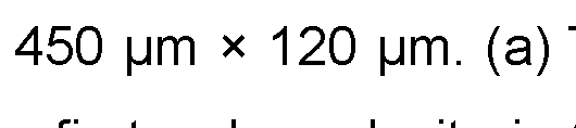
  • Channels of the following dimensions: (i) 600 mm (W) x 125 mm (H); or (ii) 450 pm (W) x 120 (H) are particularly suitable for use in the device of the present invention.
  • the channel comprises at least one inlet configured to introduce a fluid into a proximal end portion of the channel. Additionally, or alternatively, the channel comprises at least one outlet which is located at a downstream portion of the channel positioned substantially along the longitudinal axis of the channel. Ideally, the channel comprises at least two outlets.
  • a fluid can be introduced through the first inlet and flowed through the at least one channel. Through exposure to the acoustic pressure generated by the SSAW transducer and/or acoustic wave source, particles present in the fluid can be separated into different specific outlets of the channel according to particle shape and/or size.
  • the standing wave from the SSAW transducers and acoustic wave source can control movement of particles both laterally and vertically in channel.
  • said inlet(s) and/or outlet(s) are branched to permit separation of particles into different flow streams.
  • said inlet(s) and/or outlet(s) comprise tubing to permit flow of a fluid into the inlet(s) and/or out of the outlet(s).
  • said device comprises a pump to control flow rate of fluid through the inlet(s)/channel(s)/outlet(s).
  • said device comprises a plurality of channels in fluid communication with one another.
  • the channels are connected in series, so that each channel shares a connection with at least another channel.
  • each channel is connected via tubing.
  • each channel is functionally coupled with at least one IDT deposited on the surface of a piezoelectric substrate or a SSAW transducer such that each channel can separate different particles with respect to one another according to the standing wave generated for each respective channel. In this arrangement multi-stage particle separation can be achieved.
  • the SSAW transducers and/or acoustic wave source can be operated in phase with each other, or operated out of phase with each other.
  • Each SSAW transducer and/or acoustic wave source of the present disclosure may have individual electrical attachments (e.g. electrodes), so that each SSAW transducer and/or acoustic wave source can be individually controlled for frequency and power. Configuration allows for not only the generation of a multi-dimensional acoustic standing wave, but also improved control of the acoustic standing wave. In this way, it is possible to drive individual transducers with arbitrary phasing and/or different or variable frequencies and/or in various out-of-phase modes.
  • each SSAW transducer and/or acoustic wave source can generate a resonance frequency, or a mean resonance frequency, of between about 100 kHz to 1000 MHz and more preferably between about 1 MHz to 60 MHz.
  • the device disclosed therein herein can be used to separate acoustically active particles from fluids.
  • particles and cells e.g., target particles
  • the fluids can be biological based (e.g., a bodily fluid such as blood) or non-biological based (e.g., waste water).
  • acoustic focusing of cells and particles is a technique that can be used in cytometric applications.
  • Acoustic focusing can be implemented in devices for purifying and enriching samples prior to analysis of use of the samples for various applications such as prior to therapeutic injection or diagnosis.
  • a purified or enriched sample can be integrated into a conventional flow cytometer for further analysis.
  • the acoustic manipulation of particles described herein can be used in clinical applications, requiring the separation of micro- and/or nano-particles.
  • the invention can be used to manipulate, separate and/or enrich viruses, cells, cell clusters, organisms, tissues, bacteria, exosomes, platelets, parasites, worms, nanotubes, fibres, beads, zebrafish, apoptotic bodies, microvesicles, lipoproteins, liposomes, aerosols, droplets and other nanoparticle and/or microparticle components in biological fluids.
  • the invention can be used to separate two different sizes of cells.
  • the invention can be used to separate two different sized cancer cells or to separate cancer cells or disease infected cells (e.g. pathogen infected cells) from healthy cells.
  • a method for separating a mixture of particles comprising use of the device as defined herein.
  • a method typically comprises suspending a mixture of acoustically active particles in a liquid flow stream and flowing said flow stream through the channel of the device of the first aspect invention, thereby exposing the flow stream in the channel to a standing acoustic wave field to affect acoustic fluid relocation of said acoustically active particles.
  • any feature disclosed herein may be replaced by an alternative feature serving the same or a similar purpose.
  • FIG. 1 A partial side sectional view of the acoustofluidic device according to the invention; Figure 2. Cross sectional side views of the channels of the state of the art (a- b) and according to the invention (c-d).
  • a typical acoustofluidic structure consisting of a PDMS channel and a SSAW transducer (SAW-PDMS).
  • SAW-PDMS a typical acoustofluidic structure consisting of a PDMS channel and a SSAW transducer
  • SAW-Glass A hybrid acoustofluidic resonator employing a glass slide as the reflector positioned at the top of the PDMS channel
  • the maximum pressure in the SAW- PDMS and SAW-Glass is 13.4 kPa and 33.6 kPa, respectively
  • the amplitude of the first-order velocity in the SAW-PDMS and SAW-Glass is 5.42 mm/s and 37.6 mm/s, respectively
  • the maximum second-order velocity in the SAW-PDMS and SAW-Glass is 0.65 mm/s and 12.2 mm/s, respectively.;
  • Figure 4 Particle trajectories and velocities in the SAW-PDMS and SAW- Glass configurations
  • Particle size is 1 mm , the maximum velocity is 0.55 pm/s in SAW-PDMS and 5.89 mm /s in SAW-Glass.
  • Particle size is 5 mm , the maximum velocity is 0.65 mm /s in SAW-PDMS and 10.7 mm /s in SAW- Glass.
  • Particle size is 10 mm, the maximum velocity is 10.4 mm/s in SAW- PDMS and 40.8 mm /s in SAW-Glass;
  • the maximum pressure is 14.2 kPa and 224 kPa, respectively .
  • the amplitude of the first-order velocity is 2.0 mm/s and 70.6 mm/s, respectively
  • the maximum second-order velocity is 0.88 mm /s and 41 .5 mm/s, respectively;
  • Figure 6 Plots of the maximum first-order acoustic pressure p 1 (a) and the acoustic pressure distribution (b) for phase difference Af between 0 and 2p in the SAW-SAW configuration;
  • the maximum pressure is 373 kPa.
  • the maximum first-order velocity is 295 mm/s.
  • the maximum time-averaged second-order velocity is 161 mm /s.
  • the maximum pressure achieves 3,200 kPa when the BAW amplitude is ten times higher than the SAW;
  • A An acoustofluidic configuration comprising PDMS channel sidewalls, a piezoelectric substrate top plate and a piezoelectric substrate bottom plate.
  • a single IDT is deposited on the surface of each of the top and bottom plates, wherein the IDTs of the top and bottom plates are positioned adjacent to and on the same side of the channel sidewalls.
  • FIG. 1 An acoustofluidic configuration comprising PDMS channel sidewalls, a piezoelectric substrate top plate and a piezoelectric substrate bottom plate.
  • a single IDT is deposited on the surface of each of the top and bottom plates, wherein the IDTs of the top and bottom plates are positioned adjacent to and on the opposite side of the channel sidewalls.
  • An acoustofluidic configuration comprising PZT (or any other piezoelectric substrate) sidewalls, a top BAW transducer and a piezoelectric bottom plate.
  • a single IDT is deposited on the surface of the bottom plate, adjacent to the channel sidewalls.
  • a pair of IDTs forming a SSAW transducer may be deposited on the surface of the bottom plate.
  • FIG. 1 a partial side sectional diagrammatic view of an exemplar acoustofluidic device [1 ] according to an embodiment of the invention.
  • a channel [2] is bonded to the surface of a piezoelectric substrate [3a] between ideally, although not exclusively, a pair of interdigitated transducers (IDTs) [3b] forming a SSAW transducer [3]
  • IDTs interdigitated transducers
  • SSAW transducer At least one pair of IDTs [3b] is provided to generate at least one SSAW transducer [3]
  • alternative arrangements are envisaged such as where a single IDT [3b] or more than one pair of IDTs [3b] are provided to generate one of more SSAWs.
  • the IDTs are routine in the art and comprise electrodes deposited on the surface of a piezoelectric substrate to form a periodic structure and, upon application of RF voltage, convert electric signals to surface acoustic waves (SAW) by generating periodically distributed mechanical forces via a piezoelectric effect causing the substrate to expand and contract.
  • SAW surface acoustic waves
  • the pair of IDTs [3b] when an RF voltage is applied to the pair of IDTs [3b] this generates two series of identical SAWs within the piezoelectric substrate that propagate in counter directions towards one another wherein they interfere to generate a SSAW field of periodic pressure nodes and antinodes in the space in between said pair of IDTs [3b] i.e. where the channel [2] is located, thereby exposing a flow stream in the channel to a standing acoustic wave field to affect acoustic fluid relocation of acoustically active particles contained therein.
  • the channel is configured such that the longitudinal axis of same is substantially orthogonal with respect to the IDTs [3b] such that acoustic waves generated by the IDTs [3b] are substantially transverse thus exposing any particles present in the fluid to lateral pressure force permitting generation of fluid flow paths that allow separation of particles according to shape and/or size.
  • a fluid can be introduced through the first inlet [4] and flowed through the at least one channel [2] and out of the fluid outlet [5]
  • the standing acoustic wave generated by the SSAW transducer [3] and/or acoustic wave source (best seen in figure 2), particles present in the fluid can be separated into different specific outlets [5] of the channel according to particle shape and/or size.
  • the channel [2] comprises at least two outlets [5], although more or less outlets can be envisaged according to the particles to be separated.
  • said inlet(s) [4] and/or outlet(s) [5] are branched to permit separation of particles into different flow streams, although equally they may be unbranched.
  • the device may comprise a pump (not shown) to control flow rate of fluid through the inlet(s)/channel(s)/outlet(s).
  • a pump not shown
  • said inlet(s) [4] and/or outlets(s) [5] are provided with tubing to permit flow of a fluid into the inlet(s) [4a] and/or out of the outlet(s) [5b]
  • a single channel [2] is provided to allow a single staged particle separation stage.
  • a single channel [2] positioned between multiple staggered pairs of IDTs [3b] may be provided wherein each pair of IDTs [3b] produces a separate SSAW thereby providing differing fields of separation along the flow path.
  • the device [1 ] comprises a plurality of channels [2] (not shown) in fluid communication with one another.
  • the channels are connected in series, so that each channel shares a connection with at least another channel, wherein the outlet of a first channel forms the inlet for the second, and so on.
  • each channel is connected via tubing.
  • each channel comprises a SSAW transducer such that each channel can separate different particles with respect to one another according to the standing wave generated for each respective channel. In this arrangement multi-stage particle separation can be achieved.
  • the channel comprises a first sidewall [2a] and second sidewall [2b], a floor [2c], and an acoustic waves source [7] defining the roof [2d]
  • said channel floor [2c] is configured to functionally couple with the at least one SSAW transducer [3] such that the SSAW from the IDTs [3b] is propagated across same.
  • said floor [2c] of the channel [2] is provided by the piezoelectric substrate [3a] wherein the walls [2a/2b] of the channel [2] are bonded to the surface of the substrate [3a] to provide a channel.
  • said channel floor and/or walls can be made from any suitable material that can house a fluid mixture and permits coupling of the acoustic wave energy from the piezoelectric substrate to the fluid in the channel.
  • silicon, glass, or metal materials are commonly used for acoustophoresis because the rigid channel walls provide a near ideal acoustic boundary against the sample fluid, enhancing the required standing wave resonance.
  • suitable materials for channel floor and/or wall include, but are not limited to, medical grade plastics, but most ideally, said channel walls and/or floor are PDMS.
  • an acoustic wave source [7] refers to any means for generating acoustic wave energy wherein said acoustic wave energy is transmitted into the fluid of the channel [2]
  • a roof [2d] defined by an acoustic wave source [7] one can further generate a vertical pressure field in the channel, in addition to the longitudinal pressure field induced by the orthogonal IDTs, producing another standing wave thereby increasing the channel pressure field.
  • the vertical channel pressure field also permits manipulation of particles in the vertical direction of the channel in addition to laterally.
  • the acoustic wave source [7] is provided as a further SSAW transducer [7a] thus forming two SSAW transducers (i.e. as the channel floor [3] and roof [7a]), termed SAW-SAW.
  • each SSAW transducer [3], [7a] can be independently controlled such that the acoustic waves generated by same can be carefully controlled to manipulate particle flow in both vertical and lateral planes thus providing for an extra level of particle flow separation.
  • the acoustic wave source is provided as a bulk acoustic piezoelectric transducer [7b] producing bulk acoustic waves (BAWs).
  • BAWs bulk acoustic waves
  • BAW- SAW the channel floor [2c] is provided by the SSAW transducer of the substrate and the roof [2d] is defined by a bulk acoustic (BAW) piezoelectric transducer [7b]
  • BAW bulk acoustic
  • the SSAW transducers [3] and/or acoustic wave source [7a, 7b] can be operated in phase with each other, or operated out of phase with each other depending on the configuration.
  • Each SSAW transducer [3] and/or acoustic wave source [7a, 7b] of the present disclosure may have individual electrical attachments (e.g. electrodes), so that each SSAW transducer and/or acoustic wave source can be individually controlled for frequency and power.
  • Configuration allows for not only the generation of a multi-dimensional acoustic standing wave, but also improved control of the acoustic standing wave. In this way, it is possible to drive individual transducers with arbitrary phasing and/or different or variable frequencies and/or in various out-of-phase modes.
  • the channel [2] takes the form predominantly of a longitudinal channel whose dimensions (height and width) can vary according to the nature of the fluid to be flowed therethrough, the number of particles to be separated, or respective number of inlet and outlet channels, for example. It has been found that where the channel dimensions are proportionally greater in width than height, maximum pressure field can be achieved across the entire cross-section of the channel allowing more careful particle manipulation. Ideally, said channel has a width between about 400-650 mm and a height between about 100-150 mm, although variations outside these ranges are possible and within the spirit of the invention.
  • v is the vector of fluid velocity, is the fluid pressure, and are the shear viscosity and bulk viscosity
  • (X) denotes the temporal average of X over an oscillation period.
  • Eq. (19) can be solved with specific boundary conditions (see descriptions below) to obtain which can be substituted into Eq. (18) to determine the
  • Eq. (30) can be used to calculate the particle velocity.
  • Fig. 2(a-d) The four different model configurations considered in this study are shown in Fig. 2(a-d).
  • Stable acoustic pressure gradients are formed in the water flowing in the channel which exerts acoustic radiation force and streaming drag force on the particles inside the channel.
  • SAW-PDMS This typical acoustofluidic structure.
  • FIG. 2(b) shows the model of the novel structure of an acoustofluidic chip 29 ⁇ 30 for high throughput CTC separation, which employs a glass slide as an acoustic reflector attached on the top of the channel, namely hybrid PDMS-glass resonator (we call it SAW-Glass).
  • the reflector prevents the acoustic energy loss caused by the PDMS absorption on the top.
  • Fig. 2(c) the top wall of the PDMS channel is replaced by a second SSAW transducer which configures into a sandwich SSAW transducer spacing by PDMS walls, we call this structure as SAW-SAW.
  • SAW-SAW The SAW-SAW model can provide stronger pressure gradients in the channel by replacing the passive glass top with the active SSAW transducer.
  • 2(d) is a variance of the sandwich structure by replacing the top wall with a BAW transducer producing acoustic wave into the water, namely BAW-SAW.
  • the channel is constructed by two PDMS walls supporting the BAW transducer.
  • RF signals are driving both the BAW and SSAW transducers to produce a combined acoustic energy in the channel.
  • Changing the input voltage of the BAW and SSAW transducers can vary the integrated acoustic field.
  • n is the normal vector of the solid boundary surface.
  • Eq. (38) and Eq. (34) apply to the top and the bottom boundaries respectively.
  • Fig. 3(a) shows the first-order pressure gradient inside the SAW-PDMS
  • the maximum pressure is 33.6 kPa in the SAW-Glass structure which has a similar pressure distribution reported by Wu’s work 29 , where the pressure anti-nodes located near the four corners of the channel. Comparing with the maximum pressure of 13.4 kPa in the SAW-PDMS, the higher acoustic pressure in the SAW-Glass channel is achieved attributing to the reflected acoustic energy at the water-glass interface.
  • Fig. 3(b) shows the first-order velocity inside the SAW-PDMS and SAW-
  • the amplitude of the actuation velocity is less than the amplitude of the first-order velocity in both SAW-PDMS (5.42 mm/s) and SAW-Glass (37.6 mm/s) structures.
  • the glass reflector produces 89% reflection at the water-glass interface allowing the acoustic wave to travel back to the channel, which results approximately 7-fold greater first-order velocity comparing to that in the SAW-PDMS configuration.
  • the time-averaged second-order velocities in the SAW-PDMS and SAW- Glass are given in Fig. 3(c), with the maximum velocity of 0.65 m m/s and 12.2 m m/s, respectively.
  • the reflected wave from the water-glass interface interacts with the leaky wave in the water produced by the bottom SSAW transducer to produce a pseudo-standing wave (PSW) on the z direction.
  • PSW pseudo-standing wave
  • the PSW can be further improved and controlled by using another SSAW or BAW transducer such as PZT to replace the glass positioned on the top of the channel (Fig. 2(c) and Fig. 2(d)).
  • the phase difference, Af between the two SSAWs generated on the top and the bottom SSAW devices can be controlled by a signal generator, which can enhance the acoustic energy within the channel and control the distribution of the pressure field.
  • the first-order acoustic pressure the first-order velocity field
  • Varying the phase difference Af between the top and bottom SSAW transducers can redistribute the pressure gradients and alter the pressure amplitude in the channel, due to the phase shift results in an interchange in the position of the nodes and the anti-nodes.
  • the maximum acoustic pressure and pressure gradients are shown in Fig. 6(a).
  • the hybrid device achieved even larger acoustic pressure and allowed more powerful particle manipulation.
  • the hybrid device achieved even larger acoustic pressure and allowed more powerful particle manipulation.
  • the BAW and the SSAW transducers produce the same vertical vibration amplitude, i.e. the pressure anti-nodes are asymmetrical as shown in Fig. 7(a).
  • the particle trajectories in the BAW-SAW configuration are simulated in Fig. 9 right panel, which can be compared with that in the SAW-SAW configuration shown in Fig. 9 left panel. Both configurations struggle to concentrate particles due to the strong drag force dominating over the radiation force. Particles sized 5 and 10 mm are effectively driven by both the SAW-SAW and the BAW-SAW, the latter configuration displays much faster transition velocities achieving 847 mm/s and 3,310 mm/s for 5 and 10 mm, respectively.
  • the 10-pm particles migrate at the maximum velocity of 3,310 mm/s when the BAW actuation amplitude is 10 times larger than the SAW actuation.
  • the future work is to manufacture the SAW-SAW and BAW-SAW acoustofluidic chips to verify the model system and numerical analysis.

Landscapes

  • Chemical & Material Sciences (AREA)
  • Chemical Kinetics & Catalysis (AREA)
  • Engineering & Computer Science (AREA)
  • Health & Medical Sciences (AREA)
  • Mechanical Engineering (AREA)
  • Dispersion Chemistry (AREA)
  • General Health & Medical Sciences (AREA)
  • Hematology (AREA)
  • Clinical Laboratory Science (AREA)
  • Analytical Chemistry (AREA)
  • Physics & Mathematics (AREA)
  • Acoustics & Sound (AREA)
  • Multimedia (AREA)
  • Physical Or Chemical Processes And Apparatus (AREA)

Abstract

The invention concerns a novel acoustofluidic device to separate acoustically active particles from fluids comprising a novel device arrangement for improved acoustic pressure and particle velocity; and a method of separating particles from a fluid comprising use of same.

Description

Acoustofluidic Device
Field of the Invention
The invention concerns a novel acoustofluidic device to separate acoustically active particles from fluids comprising a novel device arrangement for improved acoustic pressure and particle velocity; and a method of separating particles from a fluid comprising use of same.
Background of the Invention
Acoustophoresis is the separation of particles using acoustic wave. It has been known that acoustic wave can exert forces on particles in the acoustic field which can be determined by the particles’ volume, density and compressibility. The pressure profile in a standing acoustic wave contains areas of net zero pressure at the nodes and of maximum at the anti-nodes. Depending on the acoustic contract factor of the particles, they will be trapped at the pressure nodes or pressure anti-nodes of the standing acoustic wave.
A wide range of acoustofluidic devices integrating a channel and acoustic transducer have been developed for applications in biochemistry and biomedicine. Acoustofluidic technology involves the use of acoustic radiation force to generate acoustic pressure across a flow channel. Recently, acoustofluidic manipulation of microparticles (i.e. particles with dimensions between about 0.1 and about 1000 mm ) such as bacteria, blood cells, circulating tumour cells (CTCs) and extracellular vesicles, has received attention in biochemical, biophysical, and biomedical areas due to its biocompatible, versatile, contactless and label-free advantages.
Devices based on surface acoustic waves (SAWs) producing acoustophoretic motion independent of the acoustic impedance ratio at the boundary which allows the water-filled channel to be made from either acoustically hard (e.g. silicone, pyrex) or soft materials (e.g. polydimethylsiloxane (PDMS)). SAWs versatility also enables droplet actuation with free boundary conditions. SAW based acoustophoretic devices integrate an acoustic source and channel, where the acoustic energy is coupled to fluid in the channel via the soft and/or hard walls defining said channel.
The principle of the separation by SAW devices is driven by the primary acoustic radiation force Frad, and acoustic streaming drag force Fdra9 induced by the acoustic waves. Due to the attenuation of the acoustically soft channel material, acoustic waves propagating inside the channel are absorbed into the channel material resulting in acoustic energy loss. Techniques have been explored to manipulate the particle in the channel and controlling the movement along the vertical direction by adjusting the input power from the transducers, however, smaller particles require higher input power. Further, the height of channel further limits the size of samples that can be processed. Increasing the input power of the SAW device may be able to compensate the loss but the induced Joule heat on the interdigital transducers (IDTs) can damage the piezoelectric substrate, such as lithium niobate (LiNbCh) which has high electro-mechanical coupling coefficient but poor thermal conductivity. Thus, the maximum power received by the SAW device is typically constrained by thermal stress produced by the IDTs on the substrate.
Therefore, conventional acoustophoresis devices have had limited efficacy due to several factors including inefficient heat dissipation and weak mechanical sustainability. Improved acoustophoresis devices using innovative acoustic structure are therefore desirable.
In this work, we have developed an alternative acoustofluidic device wherein we have employed a channel having a roof comprised of an active acoustic source. By doing so, significantly reduced acoustic energy loss and increased acoustic pressure inside the channel is achievable leading to vastly improved channel flow velocities compared to conventional devices. Further, the provision of an active acoustic source can be carefully controlled as an adjustable actuator, which can further increase the acoustic energy density in the channel to enhance acoustic manipulation of particles. Statements of Invention
According to a first aspect of the invention there is provided an acoustofluidic device comprising:
- at least one interdigitated transducer (IDT) deposited on the surface of a piezoelectric substrate; and
- functionally coupled therewith at least one channel having a first end and second end forming a fluid flow path, wherein said channel is positioned adjacent said at least one IDT and comprises a first sidewall; a second sidewall; a floor and an acoustic wave source defining a roof of the channel.
Reference herein to an IDT refers to a transducer comprising two interlocking comb-shaped arrays of metallic electrodes (in the fashion of a zipper), also known as interdigital electrodes (IDEs). These metallic electrodes are deposited on the surface of a piezoelectric substrate to form a periodic structure and, upon application of radio frequency (RF) voltage, convert electric signals to surface acoustic waves (SAW) by generating periodically distributed mechanical forces via a piezoelectric effect causing the substrate to expand and contract. In the case of the present arrangement, when an RF voltage is applied to the at least one IDT this generates a single travelling SAW within the piezoelectric substrate that propagates toward the channel positioned adjacent thereto. Without wishing to be bound by theory, internal reflection of the SAW from the channel wall reflects the SAW towards the IDT in a counter direction such that the outgoing SAW and reflected SAW travel towards one another wherein they interfere to generate a standing surface acoustic wave (SSAW) field of periodic pressure nodes and pressure antinodes in channel.
More preferably, the device comprises at least a pair of interdigitated transducers (IDTs) deposited on the surface of a piezoelectric substrate to form at least one SSAW transducer wherein the at least one channel is positioned between said at least one pair of IDTs. As is known to those skilled in the art, SSAW transducers comprise a piezoelectric substrate patterned with at least two interdigital transducers IDTs
According to this preferred embodiment of the invention, the at least one channel is positioned between said pair of IDTs at the point wherein the SSAW field is generated. While the SSAWs transmit along the fluid/solid interface of the channel(s) as a transverse wave, upon entering the fluid this becomes a longitudinal wave and causes a pressure field inside the fluid. As a result, particles suspended in the fluid are subjected to lateral acoustic forces due to the acoustic radiation and pressure fluctuations, which allow manipulation of the particles by changing the parameter of the IDTs such as input power, frequency, length, number of electrodes, and spacing between two IDTs.
Reference herein to a piezoelectric substrate refers to any material that exhibits a piezoelectric effect, that is the internal generation of electrical charge resulting from an applied mechanical force (and so also exhibit the reverse piezoelectric effect, that is the internal generation of a mechanical strain resulting from an applied electrical field). Examples include, but are not limited to, polyvinylidene difluoride Gallium Nitride (GaN), Aluminium nitride
Figure imgf000005_0008
(AIN), Silicon carbide (SiC), Aluminum Gallium Nitride Langasite
Figure imgf000005_0010
, Gallium orthophosphate a Lithium niobate
Figure imgf000005_0007
Figure imgf000005_0003
Figure imgf000005_0005
Lithium tantalate
Figure imgf000005_0009
, Barium titanate
Figure imgf000005_0011
, Lead zirconate titanate with or more commonly known as PZT), Potassium
Figure imgf000005_0001
Figure imgf000005_0002
niobate Sodium tungstate , and Zinc oxide (ZnO). In a
Figure imgf000005_0012
Figure imgf000005_0006
preferred embodiment of the invention, said piezoelectric substrate is Lithium niobate
Figure imgf000005_0004
In a preferred embodiment, the longitudinal axis of said channel is substantially orthogonal with respect to said IDT(s). As will be appreciated, in this arrangement as fluid flows through said channel, acoustic wave forms generated by the IDT(s) are substantially transverse to the fluid flow path, thus exposing any particles present in the fluid to lateral pressure force permitting generation of fluid flow paths that allow separation of particles according to shape and/or size. Alternatively, the longitudinal axis of said channel is provided at an angle with respect to said IDT(s) (and therefore SAW generated by same), which results in the generation of a tapered SSAW within the channel to facilitate particle separation as the particles flow through the channel. Preferably, said angle is between 0 and 90 degrees or any 1 degree increment therebetween.
In a preferred embodiment, said channel floor is configured to functionally couple with the at least one IDT or SSAW transducer such that the travelling wave or SAWs, respectively, is propagated across same. As will be appreciated, in this preferred embodiment said floor of the channel is provided by the piezoelectric substrate wherein the walls of the channel are bonded to the surface of the substrate to provide a channel.
Alternatively, said channel floor and/or walls can be made from any suitable material that can house a fluid mixture and permits coupling of the acoustic wave energy from the piezoelectric substrate to the fluid in the channel. As is known by those skilled in the art, silicon, glass, or metal materials are commonly used for acoustophoresis because the rigid channel walls provide a near ideal acoustic boundary against the sample fluid, enhancing the required standing wave resonance. Such suitable materials for channel floor and/or wall include, but are not limited to, medical grade plastics, such as polycarbonates or polymethyl methacrylates, polyphenylsulfone (PPS), glass, silicone, ceramic, elastomers, thermoset polyester (TPE), poly-methyl methacrylate (PMMA), polystyrene (PS), polycarbonate (PC), poly-ethylene glycol diacrylate (PEGDA), teflons, polyurethane (PU), paper, hydrogels, pyrex and polydimethyl siloxane (PDMS). Most ideally, said channel walls and/or floor are PDMS and silicone. In yet a further preferred embodiment, the material may be configured to be transparent to permit visualisation of the flow of fluid during operation of the device.
Reference herein to an acoustic wave source refers to any means for generating acoustic wave energy wherein said acoustic wave energy is transmitted into the fluid of the channel. Without wishing to be bound by theory, it is believed that by providing a roof defined by an acoustic wave source one can further generate and enhance a vertical pressure field in the channel, in addition to the longitudinal pressure field induced by the substantially orthogonal IDT(s), producing another standing wave thereby increasing the channel pressure field. Further, the vertical channel pressure field also permits manipulation of particles in the vertical direction of the channel in addition to laterally.
In a preferred embodiment, said acoustic wave source is provided as a further at least one interdigitated transducer (IDT) deposited on the surface of a piezoelectric substrate or standing surface acoustic wave (SSAW) transducer as defined herein. Preferably, said acoustic wave source is provided as a further standing surface acoustic wave (SSAW) transducer as defined herein. As will be appreciated by those skilled in the art, in this arrangement the channel roof and floor is provided by two substantially opposing SSAW transducers which, with the channel walls, define the channel therebetween (SAW-SAW). In this arrangement one can achieve stronger pressure gradients in the channel, thus achieving increased flow rates compared to conventional arrangements known in the art. Further, by tuning the phase difference between the waves generated by the roof and floor SSAW transducers, the acoustic pressure distribution can be controlled permitting greater particle manipulation.
In a preferred embodiment of this arrangement, the IDT(s) deposited on the surface of the piezoelectric substrate and the acoustic wave source are configured such that, in use, a phase difference of between about Df=tt/2 and Df=3tt/2 exists between the acoustic wave(s) originating in the piezoelectric substrate (e.g. the floor SSAW transducer) and the acoustic wave(s) originating in the roof of the channel (e.g. the roof SSAW transducer). Most ideally, the phase difference is about Af= tt, which has been found to produce four symmetrical pressure anti-nodes to form good particle trajectories. In an alternative embodiment, and more ideally, said acoustic wave source is provided as a bulk acoustic wave (BAW) piezoelectric transducer producing bulk acoustic waves (BAWs). In this arrangement (called BAW-SAW) the channel floor is provided by the at least one IDT or SSAW transducer of the substrate and the roof is defined by a bulk acoustic (BAW) piezoelectric transducer. It has been found that in this particular arrangement one can also achieve stronger pressure gradients in the channel of several orders of magnitude greater than conventional arrangements known in the art. RF signals drive both the BAW and SSAW transducers to produce a combined acoustic energy in the channel. Changing the input voltage of the BAW and SSAW transducers can vary the integrated acoustic field. In a preferred embodiment of this arrangement, the vibration amplitude of the BAW transducer is at least two times the vibration amplitude of the SSAW transducer, more preferably at least five times, and most ideally at least ten times which has been found to produce four symmetrical pressure anti-nodes to form good particle trajectories.
In all embodiments, advantageously it has been found that the pressure gradients achievable can be further increased by cooling the at least one SSAW transducer such that increased input voltages can be applied and thus counter any excess heating of same.
In a preferred embodiment of this arrangement, said BAW piezoelectric transducer is a piezoelectric ceramic such as, but not limited to, PZT, LiNbO3, or the like.
In a preferred embodiment, said channel has a width to height ratio of between about 10: 1 and 1 : 1 . More preferably, said channel has a width to height ratio of between about 6: 1 and 3: 1. In this arrangement, it has been found that where the channel dimensions are proportionally greater in width than height, maximum pressure field can be achieved across the entire cross-section of the channel allowing more careful particle manipulation. In yet a further preferred embodiment, said channel has a width between about 10-1000 mm including every 1 mm therebetween. More preferably, said channel has a width between about 100-750 mm , and more preferably still between about 300-700 mm , and most preferably between about 400-650 mm .
In a yet further preferred embodiment, said channel has a height between about 1 -250 mm including every 1 mm therebetween. More preferably, said channel has a height between about 25-200 mm , and most preferably between about 100-150 mm .
Channels of the following dimensions: (i) 600 mm (W) x 125 mm (H); or (ii) 450 pm (W) x 120 (H) are particularly suitable for use in the device of the present invention.
In yet a further preferred embodiment of the invention, the channel comprises at least one inlet configured to introduce a fluid into a proximal end portion of the channel. Additionally, or alternatively, the channel comprises at least one outlet which is located at a downstream portion of the channel positioned substantially along the longitudinal axis of the channel. Ideally, the channel comprises at least two outlets. As will be appreciated by those skilled in the art, in this embodiment, a fluid can be introduced through the first inlet and flowed through the at least one channel. Through exposure to the acoustic pressure generated by the SSAW transducer and/or acoustic wave source, particles present in the fluid can be separated into different specific outlets of the channel according to particle shape and/or size. Advantageously, the standing wave from the SSAW transducers and acoustic wave source can control movement of particles both laterally and vertically in channel. Preferably, said inlet(s) and/or outlet(s) are branched to permit separation of particles into different flow streams.
In yet a further preferred embodiment, said inlet(s) and/or outlet(s) comprise tubing to permit flow of a fluid into the inlet(s) and/or out of the outlet(s). Preferably, said device comprises a pump to control flow rate of fluid through the inlet(s)/channel(s)/outlet(s).
In yet a further preferred embodiment still, said device comprises a plurality of channels in fluid communication with one another. Preferably, the channels are connected in series, so that each channel shares a connection with at least another channel. More preferably, each channel is connected via tubing. More preferably still each channel is functionally coupled with at least one IDT deposited on the surface of a piezoelectric substrate or a SSAW transducer such that each channel can separate different particles with respect to one another according to the standing wave generated for each respective channel. In this arrangement multi-stage particle separation can be achieved.
In yet a further preferred embodiment, the SSAW transducers and/or acoustic wave source can be operated in phase with each other, or operated out of phase with each other. Each SSAW transducer and/or acoustic wave source of the present disclosure may have individual electrical attachments (e.g. electrodes), so that each SSAW transducer and/or acoustic wave source can be individually controlled for frequency and power. Configuration allows for not only the generation of a multi-dimensional acoustic standing wave, but also improved control of the acoustic standing wave. In this way, it is possible to drive individual transducers with arbitrary phasing and/or different or variable frequencies and/or in various out-of-phase modes.
In yet a further preferred embodiment each SSAW transducer and/or acoustic wave source can generate a resonance frequency, or a mean resonance frequency, of between about 100 kHz to 1000 MHz and more preferably between about 1 MHz to 60 MHz.
In yet a further preferred embodiment, it may be required to modulate the frequency or voltage amplitude of the standing wave. This may be done by amplitude modulation and/or by frequency modulation. As will be appreciated by those skilled in the art, the device disclosed therein herein can be used to separate acoustically active particles from fluids. For example, particles and cells (e.g., target particles) can be removed from a fluid based on the target particles' acoustic properties with respect to the fluid in which they are contained. The fluids can be biological based (e.g., a bodily fluid such as blood) or non-biological based (e.g., waste water). For example acoustic focusing of cells and particles is a technique that can be used in cytometric applications. Acoustic focusing can be implemented in devices for purifying and enriching samples prior to analysis of use of the samples for various applications such as prior to therapeutic injection or diagnosis. In some embodiments, a purified or enriched sample can be integrated into a conventional flow cytometer for further analysis. The acoustic manipulation of particles described herein can be used in clinical applications, requiring the separation of micro- and/or nano-particles. In some embodiments, the invention can be used to manipulate, separate and/or enrich viruses, cells, cell clusters, organisms, tissues, bacteria, exosomes, platelets, parasites, worms, nanotubes, fibres, beads, zebrafish, apoptotic bodies, microvesicles, lipoproteins, liposomes, aerosols, droplets and other nanoparticle and/or microparticle components in biological fluids. In some embodiments, the invention can be used to separate two different sizes of cells. In some embodiments, the invention can be used to separate two different sized cancer cells or to separate cancer cells or disease infected cells (e.g. pathogen infected cells) from healthy cells.
According to a second aspect of the invention, there is provided a method for separating a mixture of particles comprising use of the device as defined herein. As would be appreciated by those skilled in the art, such a method typically comprises suspending a mixture of acoustically active particles in a liquid flow stream and flowing said flow stream through the channel of the device of the first aspect invention, thereby exposing the flow stream in the channel to a standing acoustic wave field to affect acoustic fluid relocation of said acoustically active particles. Throughout the description and claims of this specification, the words “comprise” and“contain” and variations of the words, for example“comprising” and“comprises”, mean“including but not limited to” and do not exclude other moieties, additives, components, integers or steps. Throughout the description and claims of this specification, the singular encompasses the plural unless the context otherwise requires. In particular, where the indefinite article is used, the specification is to be understood as contemplating plurality as well as singularity, unless the context requires otherwise.
All references, including any patent or patent application, cited in this specification are hereby incorporated by reference. No admission is made that any reference constitutes prior art. Further, no admission is made that any of the prior art constitutes part of the common general knowledge in the art.
Preferred features of each aspect of the invention may be as described in connection with any of the other aspects.
Other features of the present invention will become apparent from the following examples. Generally speaking, the invention extends to any novel one, or any novel combination, of the features disclosed in this specification (including the accompanying claims and drawings). Thus, features, integers, characteristics, compounds or chemical moieties described in conjunction with a particular aspect, embodiment or example of the invention are to be understood to be applicable to any other aspect, embodiment or example described herein, unless incompatible therewith.
Moreover, unless stated otherwise, any feature disclosed herein may be replaced by an alternative feature serving the same or a similar purpose.
The Invention will now be described by way of example only with reference to the Examples below and to the following Figures wherein:
Figure 1. A partial side sectional view of the acoustofluidic device according to the invention; Figure 2. Cross sectional side views of the channels of the state of the art (a- b) and according to the invention (c-d). (a) A typical acoustofluidic structure consisting of a PDMS channel and a SSAW transducer (SAW-PDMS). (b) A hybrid acoustofluidic resonator employing a glass slide as the reflector positioned at the top of the PDMS channel (SAW-Glass). (c) An acoustofluidic configuration equipped by two SSAW transducers as the top and bottom plates (SAW-SAW) (d) An integrated acoustofluidic configuration consisting a top BAW transducer and a bottom SAW transducer (BAW-SAW). (e) The computational domain of the model, the boundary and are modelled
Figure imgf000013_0003
Figure imgf000013_0004
as the top, bottom and side walls, respectively;
Figure 3. Colour plots of the first-order acoustic pressure t the first-order
Figure imgf000013_0002
velocity field vx and the time-averaged second-order velocity in the SAW-
Figure imgf000013_0001
PDMS and SAW-Glass channels (a) The maximum pressure in the SAW- PDMS and SAW-Glass is 13.4 kPa and 33.6 kPa, respectively (b) The amplitude of the first-order velocity in the SAW-PDMS and SAW-Glass is 5.42 mm/s and 37.6 mm/s, respectively (c) The maximum second-order velocity in the SAW-PDMS and SAW-Glass is 0.65 mm/s and 12.2 mm/s, respectively.;
Figure 4. Particle trajectories and velocities in the SAW-PDMS and SAW- Glass configurations (a) Particle size is 1 mm , the maximum velocity is 0.55 pm/s in SAW-PDMS and 5.89 mm /s in SAW-Glass. (b) Particle size is 5 mm , the maximum velocity is 0.65 mm /s in SAW-PDMS and 10.7 mm /s in SAW- Glass. (c) Particle size is 10 mm, the maximum velocity is 10.4 mm/s in SAW- PDMS and 40.8 mm /s in SAW-Glass;
Figure 5. Colour plots of the first-order acoustic pressure the first-order
Figure imgf000013_0005
velocity field
Figure imgf000013_0008
and the time-averaged second-order velocity in the SAW-
Figure imgf000013_0007
SAW channel. The left panel shows the phase difference
Figure imgf000013_0006
while the right panel shows the phase different
Figure imgf000013_0009
The maximum pressure is 14.2 kPa and 224 kPa, respectively . (b) The amplitude of the first-order velocity is 2.0 mm/s and 70.6 mm/s, respectively (c) The maximum second-order velocity is 0.88 mm /s and 41 .5 mm/s, respectively; Figure 6. Plots of the maximum first-order acoustic pressure p1 (a) and the acoustic pressure distribution (b) for phase difference Af between 0 and 2p in the SAW-SAW configuration;
Figure 7. Colour plots of the first-order acoustic pressure for the BAW-SAW
Figure imgf000014_0005
configuration when the amplitude of the vibration of the BAW is (a) the same as the SAW transducer, and (b) 10 times higher than the SAW transducer;
Figure 8. Colour plots of the first-order acoustic pressure the first-order
Figure imgf000014_0004
velocity field v± and the time-averaged second-order velocity in the BAW-
Figure imgf000014_0001
SAW configuration with the channel dimension of The
Figure imgf000014_0003
maximum pressure is 373 kPa. (b) The maximum first-order velocity is 295 mm/s. (c) The maximum time-averaged second-order velocity is 161 mm /s. (d) The maximum pressure achieves 3,200 kPa when the BAW amplitude is ten times higher than the SAW;
Figure 9. Particle trajectories and velocities in the SAW-SAW (phase difference Af = tt) and -SAW configurations (a) Particle size is
Figure imgf000014_0002
1 mm , the maximum velocity is 17.5 mm/s in SAW-SAW and 80.1 mm/s in BAW- SAW. (b) Particle size is 5 mm, the maximum velocity is 131 mm/s in SAW-SAW and 847 mm /s in BAW-SAW. (c) Particle size is 10 mm, the maximum velocity is 573 mm /s in SAW-SAW and 3310 mm/s in BAW-SAW;
Figure 10. Cross sectional side views of additional exemplary acoustofluidic devices according to the invention:
(A) An acoustofluidic configuration comprising PDMS channel sidewalls, a piezoelectric substrate top plate and a piezoelectric substrate bottom plate. A single IDT is deposited on the surface of each of the top and bottom plates, wherein the IDTs of the top and bottom plates are positioned adjacent to and on the same side of the channel sidewalls.
(B) An acoustofluidic configuration comprising PDMS channel sidewalls, a piezoelectric substrate top plate and a piezoelectric substrate bottom plate. A single IDT is deposited on the surface of each of the top and bottom plates, wherein the IDTs of the top and bottom plates are positioned adjacent to and on the opposite side of the channel sidewalls.
(C) An acoustofluidic configuration comprising PDMS channel sidewalls, a piezoelectric substrate top plate and a piezoelectric substrate bottom plate. A single IDT is deposited on the surface of the top plate, and a pair of IDTs forming a SSAW transducer are deposited on the surface of the bottom plate.
(D) An acoustofluidic configuration comprising PDMS channel sidewalls, a top BAW transducer and a piezoelectric bottom plate. A single IDT is deposited on the surface of the bottom plate, adjacent to the channel sidewalls.
(E) An acoustofluidic configuration comprising PZT (or any other piezoelectric substrate) sidewalls, a top BAW transducer and a piezoelectric bottom plate. A single IDT is deposited on the surface of the bottom plate, adjacent to the channel sidewalls. Alternatively, a pair of IDTs forming a SSAW transducer may be deposited on the surface of the bottom plate.
Table 1. Parameters used in numerical analysis at T = 25°C.
Referring to the figures and, firstly, to figure 1 there is shown a partial side sectional diagrammatic view of an exemplar acoustofluidic device [1 ] according to an embodiment of the invention. It can be seen that a channel [2] is bonded to the surface of a piezoelectric substrate [3a] between ideally, although not exclusively, a pair of interdigitated transducers (IDTs) [3b] forming a SSAW transducer [3] In this particular arrangement, at least one pair of IDTs [3b] is provided to generate at least one SSAW transducer [3] As will be appreciated, alternative arrangements are envisaged such as where a single IDT [3b] or more than one pair of IDTs [3b] are provided to generate one of more SSAWs. The IDTs are routine in the art and comprise electrodes deposited on the surface of a piezoelectric substrate to form a periodic structure and, upon application of RF voltage, convert electric signals to surface acoustic waves (SAW) by generating periodically distributed mechanical forces via a piezoelectric effect causing the substrate to expand and contract. In the case of the present arrangement, when an RF voltage is applied to the pair of IDTs [3b] this generates two series of identical SAWs within the piezoelectric substrate that propagate in counter directions towards one another wherein they interfere to generate a SSAW field of periodic pressure nodes and antinodes in the space in between said pair of IDTs [3b] i.e. where the channel [2] is located, thereby exposing a flow stream in the channel to a standing acoustic wave field to affect acoustic fluid relocation of acoustically active particles contained therein.
As is shown in figure 1 , the channel is configured such that the longitudinal axis of same is substantially orthogonal with respect to the IDTs [3b] such that acoustic waves generated by the IDTs [3b] are substantially transverse thus exposing any particles present in the fluid to lateral pressure force permitting generation of fluid flow paths that allow separation of particles according to shape and/or size.
As will be appreciated, to separate particles in a fluid it is required to provide fluid flow path through said channel [2] through which a fluid containing particles to be separated can flow. In figure 1 , this is achieved by providing at least one fluid inlet [4] configured to introduce a fluid into a proximal end portion of the channel and at least one outlet [5] located at a downstream portion of the channel positioned substantially along the longitudinal axis of the channel. As will be appreciated by those skilled in the art, in this embodiment, a fluid can be introduced through the first inlet [4] and flowed through the at least one channel [2] and out of the fluid outlet [5] Through exposure to the standing acoustic wave generated by the SSAW transducer [3] and/or acoustic wave source (best seen in figure 2), particles present in the fluid can be separated into different specific outlets [5] of the channel according to particle shape and/or size. As is shown, in a preferred arrangement the channel [2] comprises at least two outlets [5], although more or less outlets can be envisaged according to the particles to be separated. Preferably, as shown, said inlet(s) [4] and/or outlet(s) [5] are branched to permit separation of particles into different flow streams, although equally they may be unbranched. Further, the device may comprise a pump (not shown) to control flow rate of fluid through the inlet(s)/channel(s)/outlet(s). Also, by providing multiple inlets it is possible to introduce multiple fluids into the channel at any one time and so, in this arrangement, separate multiple particles from multiple fluid sources. In a preferred arrangement, said inlet(s) [4] and/or outlets(s) [5] are provided with tubing to permit flow of a fluid into the inlet(s) [4a] and/or out of the outlet(s) [5b]
According to the invention, as shown, a single channel [2] is provided to allow a single staged particle separation stage. However, in alternative arrangements it is envisaged that multiple stages of separation can be achieved. For example, a single channel [2] positioned between multiple staggered pairs of IDTs [3b] may be provided wherein each pair of IDTs [3b] produces a separate SSAW thereby providing differing fields of separation along the flow path. Alternatively, the device [1 ] comprises a plurality of channels [2] (not shown) in fluid communication with one another. Preferably, the channels are connected in series, so that each channel shares a connection with at least another channel, wherein the outlet of a first channel forms the inlet for the second, and so on. More preferably, each channel is connected via tubing. More preferably still each channel comprises a SSAW transducer such that each channel can separate different particles with respect to one another according to the standing wave generated for each respective channel. In this arrangement multi-stage particle separation can be achieved.
Turning to the channel, referring to figure 2, channel cross-sections of the art (figure 2a and b) and according to the invention (figure 2c and d) are shown as a side sectional diagrammatic views. In both arrangements (c and d), the channel comprises a first sidewall [2a] and second sidewall [2b], a floor [2c], and an acoustic waves source [7] defining the roof [2d] In the embodiments shown, said channel floor [2c] is configured to functionally couple with the at least one SSAW transducer [3] such that the SSAW from the IDTs [3b] is propagated across same. As will be appreciated, in this preferred embodiment said floor [2c] of the channel [2] is provided by the piezoelectric substrate [3a] wherein the walls [2a/2b] of the channel [2] are bonded to the surface of the substrate [3a] to provide a channel. Alternatively (not shown), said channel floor and/or walls can be made from any suitable material that can house a fluid mixture and permits coupling of the acoustic wave energy from the piezoelectric substrate to the fluid in the channel. As is known by those skilled in the art, silicon, glass, or metal materials are commonly used for acoustophoresis because the rigid channel walls provide a near ideal acoustic boundary against the sample fluid, enhancing the required standing wave resonance. Such suitable materials for channel floor and/or wall include, but are not limited to, medical grade plastics, but most ideally, said channel walls and/or floor are PDMS.
With reference to the channel roof [2d], an acoustic wave source [7] refers to any means for generating acoustic wave energy wherein said acoustic wave energy is transmitted into the fluid of the channel [2] In this way it is believed that by providing a roof [2d] defined by an acoustic wave source [7] one can further generate a vertical pressure field in the channel, in addition to the longitudinal pressure field induced by the orthogonal IDTs, producing another standing wave thereby increasing the channel pressure field. Further, the vertical channel pressure field also permits manipulation of particles in the vertical direction of the channel in addition to laterally.
In a first embodiment, as shown in figure 2c, the acoustic wave source [7] is provided as a further SSAW transducer [7a] thus forming two SSAW transducers (i.e. as the channel floor [3] and roof [7a]), termed SAW-SAW. Respectively, each SSAW transducer [3], [7a] can be independently controlled such that the acoustic waves generated by same can be carefully controlled to manipulate particle flow in both vertical and lateral planes thus providing for an extra level of particle flow separation. Preferably, to achieve higher resolution of particle flow and thus separation, it has been found that fine tuning the phase difference between each respective SSAW transducer one can generate symmetrical pressure anti-nodes to form good particle trajectories. Alternatively, in a second embodiment as shown in figure 2d, the acoustic wave source is provided as a bulk acoustic piezoelectric transducer [7b] producing bulk acoustic waves (BAWs). In this arrangement (called BAW- SAW) the channel floor [2c] is provided by the SSAW transducer of the substrate and the roof [2d] is defined by a bulk acoustic (BAW) piezoelectric transducer [7b] It has been found that in this particular arrangement one can also achieve stronger pressure gradients in the channel of several orders of magnitude greater than conventional arrangements known in the art. RF signals from a source (not shown) drive both the BAW [7b] and SSAW [3] transducers to produce a combined acoustic energy in the channel [2] Changing the input voltage of the BAW [7b] and SSAW [3] transducers can vary the integrated acoustic field.
Therefore, as will be appreciated, in all embodiments the SSAW transducers [3] and/or acoustic wave source [7a, 7b] can be operated in phase with each other, or operated out of phase with each other depending on the configuration. Each SSAW transducer [3] and/or acoustic wave source [7a, 7b] of the present disclosure may have individual electrical attachments (e.g. electrodes), so that each SSAW transducer and/or acoustic wave source can be individually controlled for frequency and power. Configuration allows for not only the generation of a multi-dimensional acoustic standing wave, but also improved control of the acoustic standing wave. In this way, it is possible to drive individual transducers with arbitrary phasing and/or different or variable frequencies and/or in various out-of-phase modes.
As will be appreciated, the channel [2] takes the form predominantly of a longitudinal channel whose dimensions (height and width) can vary according to the nature of the fluid to be flowed therethrough, the number of particles to be separated, or respective number of inlet and outlet channels, for example. It has been found that where the channel dimensions are proportionally greater in width than height, maximum pressure field can be achieved across the entire cross-section of the channel allowing more careful particle manipulation. Ideally, said channel has a width between about 400-650 mm and a height between about 100-150 mm, although variations outside these ranges are possible and within the spirit of the invention.
The flow dynamics and particle separation of the devices according to the invention are described in the following examples.
Methods
When acoustic wave is applied to a suspension of particles, the scattering of the wave on the particles will exert an acoustic radiation force that can be utilised to manipulate the particles. To understand how the design of the acoustofluidic devices affects distribution patterns of the particles in a channel, we performed numerical simulations for different design scenarios. In all cases, the channel length is significantly longer than the height and the width, and the acoustic waves are perpendicular to the longitudinal direction. Thus, the fluid flow and particle movement in the channel are investigated as two- dimensional problems.
A. Governing equations for fluid flow
For very dilute suspensions, influences of the particles on the bulk fluid flow can be neglected as long as the particle size is significantly smaller than the dimension of the channel and the acoustic wavelength. Thus, the governing equations for the bulk fluid flow are,
Figure imgf000020_0001
where b is the fluid density, the bold letter v is the vector of fluid velocity,
Figure imgf000020_0006
is the fluid pressure, and are the shear viscosity and bulk viscosity,
Figure imgf000020_0005
Figure imgf000020_0004
respectively.
In our devices, there is no fluid flow before application of acoustic waves. As a
Figure imgf000020_0002
result, the fluid density and pressure, and are uniform and time-
Figure imgf000020_0003
independent. When acoustic waves propagate through the fluid, they cause small perturbations in the density, pressure, and velocity fields, which can be expressed as,
Figure imgf000021_0001
where the subscripts 1 and 2 indicate the first and the second order terms, respectively. Higher order terms are neglected in the simulations. Additionally, we assume that is proportional to
Figure imgf000021_0006
Figure imgf000021_0005
Figure imgf000021_0002
where c0 is a constant and approximately equal to the speed of sound in the fluid. Substituting Eq. (4) through (7) into Eq. (1 ) and Eq. (2) yields the continuity and momentum equations for the first- and second-order terms:
Figure imgf000021_0003
For periodic perturbations, the time average of the Eq. (10) and (11 ) become
Figure imgf000021_0004
where (X) denotes the temporal average of X over an oscillation period.
To solve the first order equations, Eq. (8) and Eq. (9) are first combined to obtain the governing equation for
Figure imgf000022_0001
In the study, we assume the first-order fields of the density, pressure, and velocity to be harmonic time dependence, i.e.
Figure imgf000022_0002
where
Figure imgf000022_0004
which is the angular frequency, and f is the wave frequency. Substituting Eq. (15) through (17) into Eq. (9) and (14) yields,
Figure imgf000022_0003
Eq. (19) can be solved with specific boundary conditions (see descriptions below) to obtain which can be substituted into Eq. (18) to determine the
Figure imgf000022_0010
first order velocity, In the current study, however, we determined v
Figure imgf000022_0009
Figure imgf000022_0008
using an approximate method. Based on the Helmholtz decomposition theorem, a vector field can be separated into two terms: irrotational and solenoidal. Previous studies have shown that the second term for vx is negligible in the bulk fluid. It is important only within the boundary layer around a solid surface. Thus, we assumed vx to be irrotational in the bulk fluid, which can be expressed as the gradient of a velocity potential,
Figure imgf000022_0006
Substituting this relationship into Eq. (18) yields,
Figure imgf000022_0005
This is the equation used to calculate vx after solving the governing equation for
Figure imgf000022_0007
B. Governing equation for acoustophoretic trajectories of particles
Once the first order acoustic pressure p1 and velocity x are obtained, we can
Figure imgf000023_0009
determine the time-averaged acoustic radiation force
Figure imgf000023_0008
on a spherical particle, which leads to the net movement of the particles besides local oscillation is the sum of the second-order pressure and the first-order
Figure imgf000023_0010
momentum flux integrated over the particle surface,
Figure imgf000023_0003
where 5W is a fixed surface in the bulk fluid around the particle. If the particle radius is much smaller than the wave length, an analytical expression of the force has been derived by Settnes and Bruus,
Figure imgf000023_0002
where the asterisk denotes the complex conjugate of the quantity, a is the particle radius, and is the isentropic compressibility of the fluid defined as
Figure imgf000023_0011
Figure imgf000023_0001
where and s are the volume and entropy of the fluid. After neglecting second and higher order terms, The scattering coefficients and
Figure imgf000023_0004
Figure imgf000023_0006
Figure imgf000023_0007
are calculated by
Figure imgf000023_0005
where and
Figure imgf000024_0007
r is the mass density and compressibility of the particle, respectively
Figure imgf000024_0008
is called the viscous penetration depth, which characterises the boundary layer thickness. Apart from
Figure imgf000024_0010
particles also experience drag force from the viscous fluid due to the relative movement of the particle with respective to the fluid. Since the time-averaged streaming velocity is the time-averaged drag force is,
Figure imgf000024_0009
Figure imgf000024_0003
where a is the particle radius and is the particle velocity vector. Applying the
Figure imgf000024_0004
Newton’s second law of motion to the particle yields,
Figure imgf000024_0005
where is the mass of the particle. In most experimental setup, the particle acceleration time is much shorter than the time scale of experimental observation
Figure imgf000024_0006
a result, we can neglect the acceleration term in Eq. (29) to obtain an expression for
Figure imgf000024_0002
Figure imgf000024_0001
Once is determined by numerically solving Eq. (12) and Eq. (13) with the boundary conditions described below, Eq. (30) can be used to calculate the particle velocity.
C. Model configurations and boundary conditions
C1. Model configurations
The four different model configurations considered in this study are shown in Fig. 2(a-d). The typical SSAW transducer made by patterning a pair of interdigital electrodes on
Figure imgf000024_0011
bonded with a PDMS channel is given in Fig. 2(a). Operating under the same RF signal, two SAWs generated by the IDTs counter-propagate to produce a standing SAW (SSAW) within the channel. Stable acoustic pressure gradients are formed in the water flowing in the channel which exerts acoustic radiation force and streaming drag force on the particles inside the channel. We call this typical acoustofluidic structure as SAW-PDMS. Fig. 2(b) shows the model of the novel structure of an acoustofluidic chip 29· 30 for high throughput CTC separation, which employs a glass slide as an acoustic reflector attached on the top of the channel, namely hybrid PDMS-glass resonator (we call it SAW-Glass). The reflector prevents the acoustic energy loss caused by the PDMS absorption on the top.
To further increase the acoustic energy pressure in the channel for enhanced manipulation of particles, we developed two new models of acoustofluidic structures as shown in Fig. 2(c) and Fig. 2(d). In Fig. 2(c), the top wall of the PDMS channel is replaced by a second SSAW transducer which configures into a sandwich SSAW transducer spacing by PDMS walls, we call this structure as SAW-SAW, The SAW-SAW model can provide stronger pressure gradients in the channel by replacing the passive glass top with the active SSAW transducer. By tuning the phase difference between the top and bottom SSAW transducers, the acoustic pressure distribution can be controlled. The model shown in Fig. 2(d) is a variance of the sandwich structure by replacing the top wall with a BAW transducer producing acoustic wave into the water, namely BAW-SAW. The channel is constructed by two PDMS walls supporting the BAW transducer. RF signals are driving both the BAW and SSAW transducers to produce a combined acoustic energy in the channel. Changing the input voltage of the BAW and SSAW transducers can vary the integrated acoustic field. Fig. 2(e) shows the computational domain of the model, where the top (rt) and bottom (Tb) boundaries are modelled differently using the displacement boundary condition in the SAW-SAW and BAW-SAW, and impedance boundary conditions are used to model the two PDMS side walls (rs). All the parameters and values given in Table 1 are used in the numerical analysis. C2. Boundary conditions
To solve the first order pressure field, we employ the impendence or lossy-wall boundary condition at the water-PDMS interface, due to partial absorption of the acoustic energy by PDMS:
Figure imgf000026_0001
where pm and cm are the mass density of PDMS and the speed of sound in PDMS, respectively n is the normal vector of the solid boundary surface. The same lossy-wall boundary condition also applies to the water-glass interface shown in Fig. 2(b),
Figure imgf000026_0002
where and are the mass density of glass and the speed of sound in glass,
Figure imgf000026_0004
respectively. To derive the boundary condition at the water-LiNbCh interface, we considered the LiNbCh substrate to be actuated by the SSAW, and ignored the wave decay along the propagation path in the substrate because of the short path length. Thus, the displacement and the velocity of the substrate in the z direction at the interface are,
Figure imgf000026_0005
where and w0 denote displacement amplitude, time, wave number,
Figure imgf000026_0006
location on y-axis and channel width, respectively. The continuity of the displacement in the z direction requires the z component of the velocity to be continuous. Using Eq. (20), the boundary condition for at the water-
Figure imgf000026_0007
Figure imgf000026_0008
interface is,
Figure imgf000026_0003
where ez is the unit vector in the z direction. In the design of the SAW-SAW configuration, the same attenuation boundary condition as that shown in Eq. (35) applies to both the top and the bottom boundaries.
For the water-PZT interface, we simulated the design in which PZT vibrated only in the z direction. Thus, the displacement and the velocity of the substrate at this interface are,
Figure imgf000027_0001
where uT denotes the maximum displacement amplitude of the PZT surface which is controlled by the applying RF voltage. Again, the continuity of the displacement in the normal direction at the interface requires the normal velocity to be continuous. Using Eq. (20), the boundary condition for at the
Figure imgf000027_0004
water-PZT interface is,
Figure imgf000027_0002
In the design with the BAW-SAW configuration, Eq. (38) and Eq. (34) apply to the top and the bottom boundaries respectively.
D. Numerical simulations
Computational mesh with maximum element size length at the domain
Figure imgf000027_0005
boundary and 10 db in the bulk of the domain is reasonable to capture the physics of the model. We use an illustrative mesh with
Figure imgf000027_0006
where d is the viscous penetration depth defined in Eq. (27). For verifying the correctness of this solution, an investigation of the mesh-convergence is required. We compare a series of meshes with decreasing mesh element size length and define a relative convergence function C(g) for a solution g with respect to a reference solution gref taken to be the solution for the smallest value of
Figure imgf000027_0003
Figure imgf000028_0001
where we use a reference solution with which resulted in
Figure imgf000028_0003
Figure imgf000028_0002
Figure imgf000028_0006
elements.
To simulate the flow and particle distribution patterns, we first solve Eq. (19) to determine the first order pressure field pt and use it to calculate the velocity field with Eq. (20). The results are substituted into Eq. (12) and Eq. (13) to solve for the time averaged, second order velocity field . Finally, the
Figure imgf000028_0007
particle velocity and trajcetories are calculated with Eq. (30).
Results
Acoustofluidic field and particle trajectories in the SAW-PDMS and SAW- Glass
Fig. 3(a) shows the first-order pressure gradient inside the SAW-PDMS and
Figure imgf000028_0008
SAW-Glass channels. The maximum pressure is 33.6 kPa in the SAW-Glass structure which has a similar pressure distribution reported by Wu’s work 29 , where the pressure anti-nodes located near the four corners of the channel. Comparing with the maximum pressure of 13.4 kPa in the SAW-PDMS, the higher acoustic pressure in the SAW-Glass channel is achieved attributing to the reflected acoustic energy at the water-glass interface.
Fig. 3(b) shows the first-order velocity inside the SAW-PDMS and SAW-
Figure imgf000028_0005
Glass configurations, the amplitude of the actuation velocity is less than the amplitude of the first-order velocity
Figure imgf000028_0004
in both SAW-PDMS (5.42 mm/s) and SAW-Glass (37.6 mm/s) structures. The glass reflector produces 89% reflection at the water-glass interface allowing the acoustic wave to travel back to the channel, which results approximately 7-fold greater first-order velocity comparing to that in the SAW-PDMS configuration. The time-averaged second-order velocities in the SAW-PDMS and SAW- Glass are given in Fig. 3(c), with the maximum velocity of 0.65 m m/s and 12.2 m m/s, respectively.
Acoustofluidic field and particle trajectories in the SAW-SAW
In the SAW-Glass channel, the reflected wave from the water-glass interface interacts with the leaky wave in the water produced by the bottom SSAW transducer to produce a pseudo-standing wave (PSW) on the z direction. The PSW can be further improved and controlled by using another SSAW or BAW transducer such as PZT to replace the glass positioned on the top of the channel (Fig. 2(c) and Fig. 2(d)). In the SAW-SAW configuration, the phase difference, Af, between the two SSAWs generated on the top and the bottom SSAW devices can be controlled by a signal generator, which can enhance the acoustic energy within the channel and control the distribution of the pressure field. The first-order acoustic pressure the first-order velocity field
Figure imgf000029_0001
and the time-averaged second-order velocity in the are
Figure imgf000029_0002
Figure imgf000029_0003
given in Fig. 5, where the left panel and right panel show the results when and Df=tt, respectively.
Varying the phase difference Af between the top and bottom SSAW transducers can redistribute the pressure gradients and alter the pressure amplitude in the channel, due to the phase shift results in an interchange in the position of the nodes and the anti-nodes. By sweeping the Af, the maximum acoustic pressure and pressure gradients are shown in Fig. 6(a). The largest pressure of 232 kPa is obtained at Df=5tt/6 and Df=7tt/6 with four pressure anti-nodes (Fig. 6(b)), and the smallest pressure of 14.2 kPa is noted at Af=0 (Fig. 5(a)). The four pressure anti-nodes presented at Df=5tt/6 or 7TT/6 are not entirely symmetrical, which could not produce useful particle trajectories for particle separation. The maximum acoustic pressure at Df=p (red arrow in Fig. 6) is slightly lower but producing four symmetrical pressure anti-nodes (Fig. 5(a), right), which can form good particle trajectories (Fig. 9).
Acoustofluidic field and particle trajectories in the BAW-SAW By replacing the top SSAW transducer by the BAW transducer, such as PZT, as shown in Fig. 2(d), the hybrid device achieved even larger acoustic pressure and allowed more powerful particle manipulation. To allow high throughput particle manipulation by the primary acoustic radiation force to drive particles towards a belt like pressure node in the z direction, it is desired to have two pressure anti-nodes formed at the central top and bottom areas in the channel. For the same channel geometry used in the above simulations, i.e. 600 mm (W) x 125 mm (FI), when the BAW and the SSAW transducers produce the same vertical vibration amplitude, i.e.
Figure imgf000030_0001
the pressure anti-nodes are asymmetrical as shown in Fig. 7(a). We increased the amplitude of the BAW to 10 times as the amplitude of the bottom SSAW transducer, i.e.
Figure imgf000030_0002
as shown in Fig. 7(b), the two pressure anti-nodes are formed.
The particle trajectories in the BAW-SAW configuration are simulated in Fig. 9 right panel, which can be compared with that in the SAW-SAW configuration shown in Fig. 9 left panel. Both configurations struggle to concentrate
Figure imgf000030_0003
particles due to the strong drag force dominating over the radiation force. Particles sized 5 and 10 mm are effectively driven by both the SAW-SAW and the BAW-SAW, the latter configuration displays much faster transition velocities achieving 847 mm/s and 3,310 mm/s for 5 and 10 mm, respectively.
Conclusions
A comprehensive comparison amongst traditional SAW-PDMS, hybrid SAW- Glass, novel SAW-SAW and BAW-SAW structures have been presented in the study. The model of the SAW-SAW transducers has notably increased the 10- pm particle velocity to 573 mm/s, comparing to the velocity of 10.4 mm/s in the state-of-the-art hybrid SAW-Glass configuration. The active acoustic generation by the top SAW transducer instead of the passive glass reflection employs the same actuation boundary condition as the bottom IDT used in most of acoustofluidic devices. The BAW-SAW transducer whose piezoelectric material (e.g. PZT) can produce much greater vibration to incorporate with the bottom SSAW transducer allowing significantly stronger acoustic resonance generated in the channel. The 10-pm particles migrate at the maximum velocity of 3,310 mm/s when the BAW actuation amplitude is 10 times larger than the SAW actuation. The future work is to manufacture the SAW-SAW and BAW-SAW acoustofluidic chips to verify the model system and numerical analysis.
Figure imgf000031_0001
References
29. M. Wu, P. H. Huang, R. Zhang, Z. Mao, C. Chen, G. Kemeny,
P. Li, A. V. Lee, R. Gyanchandani, A. J. Armstrong, M. Dao, S. Suresh and T. J. Huang, Small (Weinheim an der Bergstrasse, Germany), 2018, 14, e1801 131 . 30. M. Wu, K. Chen, S. Yang, Z. Wang, P. H. Huang, J. Mai, Z. Y. Li and T. J. Huang, Lab on a chip, 2018, 18, 3003-3010.

Claims

1. An acoustofluidic device comprising:
- at least one interdigitated transducer (IDT) deposited on the surface of a piezoelectric substrate; and
- functionally coupled therewith at least one channel having a first end and second end forming a fluid flow path, wherein said channel is positioned adjacent said at least one IDT and comprises a first sidewall; a second sidewall; a floor and an acoustic wave source defining a roof of the channel.
2. The device according to claim 1 comprising at least a pair of interdigitated transducers (IDTs) deposited on the surface of a piezoelectric substrate to form at least one standing surface acoustic wave (SSAW) transducer wherein the at least one channel is positioned between said at least one pair of IDTs.
3. The device according to any preceding claim wherein said piezoelectric substrate is selected from the group comprising: polyvinylidene difluoride (PVDF), Gallium Nitride (GaN), Aluminium nitride (AIN), Silicon carbide (SiC), Aluminum Gallium Nitride (AIGaN), Langasite
Figure imgf000033_0007
Gallium orthophosphate , a Lithium niobate
Figure imgf000033_0004
Lithium tantalate
Figure imgf000033_0009
Barium titanate Lead
Figure imgf000033_0008
Figure imgf000033_0010
zirconate titanate with or more commonly
Figure imgf000033_0002
Figure imgf000033_0003
known as PZT), Potassium niobate Sodium tungstate
Figure imgf000033_0006
and Zinc oxide (ZnO).
Figure imgf000033_0001
4. The device according to any preceding claim wherein said piezoelectric substrate is Lithium niobate
Figure imgf000033_0005
5. The device according to any preceding claim wherein the longitudinal axis of said channel is substantially orthogonal with respect to said IDT(s).
6. The device according to any one of claims 1 -4 wherein the longitudinal axis of said channel is provided at an angle with respect to said IDT(s).
7. The device according to claim 6 wherein said angle is between 0 and 90 degrees or any 1 degree increment therebetween.
8. The device according to any preceding claim wherein said channel floor and/or walls is manufactured from a material selected from the group comprising:, polycarbonates or polymethyl methacrylates, polyphenylsulfone (PPS), glass, silicone, ceramic, elastomers, thermoset polyester (TPE), poly-methyl methacrylate (PMMA), polystyrene (PS), polycarbonate (PC), poly-ethylene glycol diacrylate (PEGDA), teflons, polyurethane (PU), paper, hydrogels, pyrex and polydimethyl siloxane (PDMS).
9. The device according to any preceding claim wherein said channel floor and/or walls is manufactured from a material selected from the group comprising: PDMS and silicone.
10. The device according to any preceding claim wherein said acoustic wave source is provided as a further at least one interdigitated transducer (IDT) deposited on the surface of a piezoelectric substrate or a standing surface acoustic wave (SSAW) transducer.
11. The device according to any preceding claim wherein said acoustic wave source is provided as a further standing surface acoustic wave (SSAW) transducer.
12. The device according to any one of claims 10 or 11 wherein said at least one IDT deposited on the surface of a piezoelectric substrate and said acoustic wave source are configured such that, in use, a phase difference of between about Df=tt/2 and Df=3tt/2 exists between the acoustic wave(s) originating in said piezoelectric substrate and the acoustic wave(s) originating in said roof of the channel.
13. The device according to claim 12 wherein, in use, a phase difference of between about Df=p exists between the acoustic wave(s) originating in said piezoelectric substrate and the acoustic wave(s) originating in said roof of the channel.
14. The device according to any one of claims 1 -9 wherein said acoustic wave source is provided as a bulk acoustic wave (BAW) piezoelectric transducer producing bulk acoustic waves (BAWs).
15. The device according to claim 14 wherein said BAW piezoelectric transducer is a piezoelectric ceramic.
16. The device according to claim 15 wherein said piezoelectric transducer is
Figure imgf000035_0001
17. The device according to any preceding claim wherein said channel has a width to height ratio of between about 10: 1 and 1 : 1 .
18. The device according to any preceding claim wherein said channel has a width between about 10-1000 mm and a height between about 1 -250 mm including every 1 mm therebetween.
19. The device according to any preceding claim wherein the channel comprises at least one inlet configured to introduce a fluid into a proximal end portion of the channel and/or at least one outlet which is located at a downstream portion of the channel positioned substantially along the longitudinal axis of the channel.
20. The device according to claim 19 wherein said inlet(s) and/or outlet(s) are branched to permit separation of particles into different flow streams.
21 . The device according to any preceding claim wherein said device comprises a plurality of channels in fluid communication with one another.
22. The device according to claim 21 wherein each channel is functionally coupled with at least one IDT deposited on the surface of a piezoelectric substrate or a SSAW transducer such that each channel can separate different particles with respect to one another according to the standing wave generated for each respective channel.
23. The device according to any preceding claim wherein the at least one IDT or SSAW transducer and/or acoustic wave source can generate a resonance frequency, or a mean resonance frequency, of between about 100 KHz to 1000 M Hz
24. The device according to claim 23 wherein the at least one IDT or SSAW transducer and/or acoustic wave source can generate a resonance frequency, or a mean resonance frequency, of between about 1 MHz to 60 MHz.
25. A method for separating a mixture of particles comprising use of the device according to any one of claims 1 -24.
PCT/EP2020/058531 2019-04-02 2020-03-26 Acoustofluidic device Ceased WO2020201004A1 (en)

Priority Applications (2)

Application Number Priority Date Filing Date Title
GB2113171.9A GB2596444A (en) 2019-04-02 2020-03-26 Acoustofluidic device
US17/599,703 US20220193663A1 (en) 2019-04-02 2020-03-26 Acoustofluidic device

Applications Claiming Priority (2)

Application Number Priority Date Filing Date Title
GB1904601.0 2019-04-02
GBGB1904601.0A GB201904601D0 (en) 2019-04-02 2019-04-02 Acoustofluidic device

Publications (1)

Publication Number Publication Date
WO2020201004A1 true WO2020201004A1 (en) 2020-10-08

Family

ID=66443046

Family Applications (1)

Application Number Title Priority Date Filing Date
PCT/EP2020/058531 Ceased WO2020201004A1 (en) 2019-04-02 2020-03-26 Acoustofluidic device

Country Status (3)

Country Link
US (1) US20220193663A1 (en)
GB (2) GB201904601D0 (en)
WO (1) WO2020201004A1 (en)

Families Citing this family (3)

* Cited by examiner, † Cited by third party
Publication number Priority date Publication date Assignee Title
US12337319B2 (en) * 2018-03-03 2025-06-24 Applied Cells Inc. Microfluidic chip for acoustic separation of biological objects
KR20240144471A (en) 2018-12-18 2024-10-02 스냅 인코포레이티드 Adaptive eyewear antenna
WO2021195793A1 (en) * 2020-03-31 2021-10-07 Quantum Matrix Spa Systems and methods for blocking, confining and decanting suspended dust present in an area

Citations (6)

* Cited by examiner, † Cited by third party
Publication number Priority date Publication date Assignee Title
US6609430B1 (en) * 2000-05-09 2003-08-26 Shrinivas G. Joshi Low profile transducer for flow meters
US20140033808A1 (en) * 2012-08-01 2014-02-06 The Penn State Research Foundation High-efficiency separation and manipulation of particles and cells in microfluidic device using surface acoustic waves at an oblique angle
WO2015058265A1 (en) * 2013-10-25 2015-04-30 Monash University Virtual deterministic lateral displacement for particle separation using surface acoustic waves
WO2016160261A1 (en) * 2015-03-31 2016-10-06 Biomet Biologics, Llc Cell washing device using standing acoustic waves and a phantom material
US20170232439A1 (en) * 2014-08-11 2017-08-17 Carnegie Mellon University Separation of low-abundance cells from fluid using surface acoustic waves
WO2019046483A1 (en) * 2017-08-29 2019-03-07 Duke University Systems, methods, and structures for surface acoustic wave-based separation

Patent Citations (6)

* Cited by examiner, † Cited by third party
Publication number Priority date Publication date Assignee Title
US6609430B1 (en) * 2000-05-09 2003-08-26 Shrinivas G. Joshi Low profile transducer for flow meters
US20140033808A1 (en) * 2012-08-01 2014-02-06 The Penn State Research Foundation High-efficiency separation and manipulation of particles and cells in microfluidic device using surface acoustic waves at an oblique angle
WO2015058265A1 (en) * 2013-10-25 2015-04-30 Monash University Virtual deterministic lateral displacement for particle separation using surface acoustic waves
US20170232439A1 (en) * 2014-08-11 2017-08-17 Carnegie Mellon University Separation of low-abundance cells from fluid using surface acoustic waves
WO2016160261A1 (en) * 2015-03-31 2016-10-06 Biomet Biologics, Llc Cell washing device using standing acoustic waves and a phantom material
WO2019046483A1 (en) * 2017-08-29 2019-03-07 Duke University Systems, methods, and structures for surface acoustic wave-based separation

Non-Patent Citations (2)

* Cited by examiner, † Cited by third party
Title
M. WUK. CHENS. YANGZ. WANGP. H. HUANGJ. MAIZ. Y. LIT. J. HUANG, LAB ON A CHIP, vol. 18, 2018, pages 3003 - 3010
M. WUP. H. HUANGR. ZHANGZ. MAOC. CHENG. KEMENYP. LIA. V. LEER. GYANCHANDANIA. J. ARMSTRONG, SMALL (WEINHEIM AN DER BERGSTRASSE, GERMANY),, vol. 14, 2018, pages e1801131

Also Published As

Publication number Publication date
US20220193663A1 (en) 2022-06-23
GB201904601D0 (en) 2019-05-15
GB202113171D0 (en) 2021-10-27
GB2596444A (en) 2021-12-29

Similar Documents

Publication Publication Date Title
Glynne-Jones et al. Acoustofluidics 9: Modelling and applications of planar resonant devices for acoustic particle manipulation
US10724029B2 (en) Acoustophoretic separation technology using multi-dimensional standing waves
Johansson et al. Surface acoustic wave induced particle manipulation in a PDMS channel—principle concepts for continuous flow applications
Chen et al. Three-dimensional numerical simulation and experimental investigation of boundary-driven streaming in surface acoustic wave microfluidics
Devendran et al. Diffraction-based acoustic manipulation in microchannels enables continuous particle and bacteria focusing
RU2708048C2 (en) Method for acoustic manipulation of particles in standing wave fields
EP2903715B1 (en) Acoustophoretic separation technology using multi-dimensional standing waves
CN104334206B (en) Acoustophoretic separation of lipid particles from red blood cells
US20160325206A1 (en) Acoustic pre-conditioner
US20220193663A1 (en) Acoustofluidic device
Hossein et al. A review of acoustofluidic separation of bioparticles
EP3288660A1 (en) Acoustophoretic device for angled wave particle deflection
Ng et al. Flow-rate-insensitive deterministic particle sorting using a combination of travelling and standing surface acoustic waves
CN104870077A (en) Microfluidic manipulation and particle sorting using tunable surface standing acoustic waves
Sahin et al. Fundamentals of acoustic wave generation and propagation
Sriphutkiat et al. Particle manipulation using standing acoustic waves in the microchannel at dual-frequency excitation: Effect of power ratio
Özer et al. An extended view for acoustofluidic particle manipulation: Scenarios for actuation modes and device resonance phenomenon for bulk-acoustic-wave devices
Anderson et al. The physics and technology of ultrasonic particle separation in air
Franke et al. Numerical simulation of surface acoustic wave actuated cell sorting
NL2008816C2 (en) Method for size-sorting microbubbles and apparatus for the same.
Devendran et al. Manipulation and patterning of micro-objects using acoustic waves
US20220186174A1 (en) Acoustic edge effect
Zhang et al. An integratible acoustic micropump based on the resonance of on-substrate sharp-edge micropillar arrays
US20230036073A1 (en) Enhanced acoustic particle processing with seeding particles
Karaman Numerical modeling and experimental investigation of cell manipulation using acoustophoresis

Legal Events

Date Code Title Description
121 Ep: the epo has been informed by wipo that ep was designated in this application

Ref document number: 20714595

Country of ref document: EP

Kind code of ref document: A1

ENP Entry into the national phase

Ref document number: 202113171

Country of ref document: GB

Kind code of ref document: A

Free format text: PCT FILING DATE = 20200326

NENP Non-entry into the national phase

Ref country code: DE

122 Ep: pct application non-entry in european phase

Ref document number: 20714595

Country of ref document: EP

Kind code of ref document: A1