WO2020196387A1 - Signal processing device, signal processing method, program and medical image processing system - Google Patents
Signal processing device, signal processing method, program and medical image processing system Download PDFInfo
- Publication number
- WO2020196387A1 WO2020196387A1 PCT/JP2020/012675 JP2020012675W WO2020196387A1 WO 2020196387 A1 WO2020196387 A1 WO 2020196387A1 JP 2020012675 W JP2020012675 W JP 2020012675W WO 2020196387 A1 WO2020196387 A1 WO 2020196387A1
- Authority
- WO
- WIPO (PCT)
- Prior art keywords
- signal processing
- edof
- restoration
- degree
- image
- Prior art date
Links
- 238000012545 processing Methods 0.000 title claims abstract description 283
- 238000003672 processing method Methods 0.000 title claims abstract description 8
- 238000003384 imaging method Methods 0.000 claims abstract description 38
- 230000003287 optical effect Effects 0.000 claims description 99
- 238000000034 method Methods 0.000 claims description 45
- 238000005516 engineering process Methods 0.000 abstract description 9
- 230000006870 function Effects 0.000 description 28
- 238000012546 transfer Methods 0.000 description 25
- 238000003780 insertion Methods 0.000 description 16
- 230000037431 insertion Effects 0.000 description 16
- 230000000694 effects Effects 0.000 description 12
- 238000010586 diagram Methods 0.000 description 10
- 230000003313 weakening effect Effects 0.000 description 9
- 230000010287 polarization Effects 0.000 description 7
- 230000007423 decrease Effects 0.000 description 6
- 230000006866 deterioration Effects 0.000 description 5
- 238000004364 calculation method Methods 0.000 description 3
- 230000003292 diminished effect Effects 0.000 description 3
- 238000001356 surgical procedure Methods 0.000 description 3
- 238000013528 artificial neural network Methods 0.000 description 2
- 238000004891 communication Methods 0.000 description 2
- 238000012937 correction Methods 0.000 description 2
- 238000005315 distribution function Methods 0.000 description 2
- 238000002674 endoscopic surgery Methods 0.000 description 2
- 238000010801 machine learning Methods 0.000 description 2
- 238000003825 pressing Methods 0.000 description 2
- 230000001954 sterilising effect Effects 0.000 description 2
- 238000004659 sterilization and disinfection Methods 0.000 description 2
- 230000015572 biosynthetic process Effects 0.000 description 1
- 238000013329 compounding Methods 0.000 description 1
- 238000001914 filtration Methods 0.000 description 1
- 229910052736 halogen Inorganic materials 0.000 description 1
- 150000002367 halogens Chemical class 0.000 description 1
- 239000004973 liquid crystal related substance Substances 0.000 description 1
- 238000005259 measurement Methods 0.000 description 1
- 230000001151 other effect Effects 0.000 description 1
- 230000002787 reinforcement Effects 0.000 description 1
- 239000004065 semiconductor Substances 0.000 description 1
- 239000007779 soft material Substances 0.000 description 1
- 238000001228 spectrum Methods 0.000 description 1
- 239000000126 substance Substances 0.000 description 1
- 238000012549 training Methods 0.000 description 1
- 229910052724 xenon Inorganic materials 0.000 description 1
- FHNFHKCVQCLJFQ-UHFFFAOYSA-N xenon atom Chemical compound [Xe] FHNFHKCVQCLJFQ-UHFFFAOYSA-N 0.000 description 1
Images


Classifications
-
- A—HUMAN NECESSITIES
- A61—MEDICAL OR VETERINARY SCIENCE; HYGIENE
- A61B—DIAGNOSIS; SURGERY; IDENTIFICATION
- A61B1/00—Instruments for performing medical examinations of the interior of cavities or tubes of the body by visual or photographical inspection, e.g. endoscopes; Illuminating arrangements therefor
- A61B1/00002—Operational features of endoscopes
- A61B1/00004—Operational features of endoscopes characterised by electronic signal processing
- A61B1/00009—Operational features of endoscopes characterised by electronic signal processing of image signals during a use of endoscope
- A61B1/000095—Operational features of endoscopes characterised by electronic signal processing of image signals during a use of endoscope for image enhancement
-
- A—HUMAN NECESSITIES
- A61—MEDICAL OR VETERINARY SCIENCE; HYGIENE
- A61B—DIAGNOSIS; SURGERY; IDENTIFICATION
- A61B1/00—Instruments for performing medical examinations of the interior of cavities or tubes of the body by visual or photographical inspection, e.g. endoscopes; Illuminating arrangements therefor
- A61B1/04—Instruments for performing medical examinations of the interior of cavities or tubes of the body by visual or photographical inspection, e.g. endoscopes; Illuminating arrangements therefor combined with photographic or television appliances
- A61B1/043—Instruments for performing medical examinations of the interior of cavities or tubes of the body by visual or photographical inspection, e.g. endoscopes; Illuminating arrangements therefor combined with photographic or television appliances for fluorescence imaging
-
- G—PHYSICS
- G02—OPTICS
- G02B—OPTICAL ELEMENTS, SYSTEMS OR APPARATUS
- G02B23/00—Telescopes, e.g. binoculars; Periscopes; Instruments for viewing the inside of hollow bodies; Viewfinders; Optical aiming or sighting devices
- G02B23/24—Instruments or systems for viewing the inside of hollow bodies, e.g. fibrescopes
- G02B23/2407—Optical details
- G02B23/2453—Optical details of the proximal end
-
- G—PHYSICS
- G02—OPTICS
- G02B—OPTICAL ELEMENTS, SYSTEMS OR APPARATUS
- G02B23/00—Telescopes, e.g. binoculars; Periscopes; Instruments for viewing the inside of hollow bodies; Viewfinders; Optical aiming or sighting devices
- G02B23/24—Instruments or systems for viewing the inside of hollow bodies, e.g. fibrescopes
- G02B23/2407—Optical details
- G02B23/2461—Illumination
-
- G—PHYSICS
- G02—OPTICS
- G02B—OPTICAL ELEMENTS, SYSTEMS OR APPARATUS
- G02B23/00—Telescopes, e.g. binoculars; Periscopes; Instruments for viewing the inside of hollow bodies; Viewfinders; Optical aiming or sighting devices
- G02B23/24—Instruments or systems for viewing the inside of hollow bodies, e.g. fibrescopes
- G02B23/2476—Non-optical details, e.g. housings, mountings, supports
- G02B23/2484—Arrangements in relation to a camera or imaging device
-
- G—PHYSICS
- G02—OPTICS
- G02B—OPTICAL ELEMENTS, SYSTEMS OR APPARATUS
- G02B27/00—Optical systems or apparatus not provided for by any of the groups G02B1/00 - G02B26/00, G02B30/00
- G02B27/0075—Optical systems or apparatus not provided for by any of the groups G02B1/00 - G02B26/00, G02B30/00 with means for altering, e.g. increasing, the depth of field or depth of focus
-
- G—PHYSICS
- G02—OPTICS
- G02B—OPTICAL ELEMENTS, SYSTEMS OR APPARATUS
- G02B5/00—Optical elements other than lenses
- G02B5/30—Polarising elements
- G02B5/3083—Birefringent or phase retarding elements
-
- G06T5/73—
-
- G—PHYSICS
- G06—COMPUTING; CALCULATING OR COUNTING
- G06T—IMAGE DATA PROCESSING OR GENERATION, IN GENERAL
- G06T7/00—Image analysis
- G06T7/50—Depth or shape recovery
- G06T7/55—Depth or shape recovery from multiple images
-
- A—HUMAN NECESSITIES
- A61—MEDICAL OR VETERINARY SCIENCE; HYGIENE
- A61B—DIAGNOSIS; SURGERY; IDENTIFICATION
- A61B1/00—Instruments for performing medical examinations of the interior of cavities or tubes of the body by visual or photographical inspection, e.g. endoscopes; Illuminating arrangements therefor
- A61B1/04—Instruments for performing medical examinations of the interior of cavities or tubes of the body by visual or photographical inspection, e.g. endoscopes; Illuminating arrangements therefor combined with photographic or television appliances
- A61B1/045—Control thereof
-
- G—PHYSICS
- G06—COMPUTING; CALCULATING OR COUNTING
- G06T—IMAGE DATA PROCESSING OR GENERATION, IN GENERAL
- G06T2207/00—Indexing scheme for image analysis or image enhancement
- G06T2207/10—Image acquisition modality
- G06T2207/10028—Range image; Depth image; 3D point clouds
Definitions
- the present disclosure relates to signal processing devices, signal processing methods, programs, and medical image processing systems, and in particular, signal processing devices, signal processing methods, programs, and signals that enable special light observation with lower noise.
- signal processing devices, signal processing methods, programs, and signals that enable special light observation with lower noise.
- the image processing apparatus disclosed in Patent Document 1 includes an EDOF optical system using a birefringence mask and a control unit that uses a function that adjusts the amount of blur according to conditions, and includes a state related to observation of a subject image.
- the subject image can be observed in a more preferable manner depending on the situation and the like.
- This disclosure has been made in view of such a situation, and is intended to enable special light observation with lower noise.
- the signal processing device on one aspect of the present disclosure performs EDOF signal processing as restoration processing on a special light image acquired by imaging an observation target irradiated with special light.
- a unit and a setting unit for setting the degree of restoration of the EDOF signal processing with respect to the EDOF signal processing unit are provided, and the setting unit is a normal light acquired by imaging the observation target irradiated with normal light.
- the parameter for the degree of restoration in the EDOF signal processing for the special light image is set so as to weaken the degree of restoration in the EDOF signal processing for the special light image rather than the degree of restoration in the EDOF signal processing as the restoration processing for the image. Set.
- the signal processing method or program of one aspect of the present disclosure is to perform EDOF (Extended Depth of Field) signal processing as restoration processing on a special light image acquired by imaging an observation target irradiated with special light. And setting the degree of restoration of the EDOF signal processing, rather than the degree of restoration in the EDOF signal processing as the restoration processing for the ordinary light image acquired by imaging the observation target irradiated with normal light.
- a parameter for the degree of restoration in the EDOF signal processing for the special light image is set so as to weaken the degree of restoration in the EDOF signal processing for the special light image.
- the medical image processing system includes a light source that irradiates an observation object with special light or normal light, and an imaging unit that images the observation object irradiated with the special light or the normal light.
- the signal processing unit includes an EDOF (Extended Depth of Field) optical system arranged on the optical axis of light incident on the imaging unit, and a signal processing unit that performs signal processing on the image captured by the imaging unit. Is an EDOF signal processing unit that performs EDOF signal processing as restoration processing on the special light image acquired by imaging the observation target irradiated with the special light, and the EDOF signal processing degree of restoration of the EDOF signal processing.
- EDOF Extended Depth of Field
- It has a setting unit for setting with respect to the signal processing unit, and the setting unit has a restoration in EDOF signal processing as a restoration processing for a normal light image acquired by imaging the observation target irradiated with the normal light.
- a parameter for the degree of restoration in the EDOF signal processing for the special light image is set so as to weaken the degree of restoration in the EDOF signal processing for the special light image.
- the degree of restoration in the EDOF signal processing for a special light image is higher than the degree of restoration in the EDOF signal processing as the restoration processing for the ordinary light image acquired by imaging the observation object irradiated with normal light.
- Parameters for the degree of restoration in EDOF signal processing for special light images are set so as to weaken.
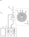
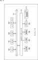
- FIG. 1 is a block diagram showing a configuration example of an embodiment of a medical image processing system to which the present technology is applied.
- the medical image processing system 11 is configured by mounting various devices for endoscopic surgery on a cart 13 on which a display device 12 is placed, for example, an endoscope. Image processing can be performed on the image acquired by the endoscope 14 used in the lower surgery.
- the display device 12 displays an image acquired by the endoscope 14, an image in which image processing has been performed on the image, and the like.
- the display device 12 can display a setting screen having a user interface as shown in FIG. 10 described later.
- the cart 13 is equipped with a light source device 21, a CCU (CCU: Camera Control Unit) 22, and a signal processing device 23.
- a light source device 21 a CCU (CCU: Camera Control Unit) 22
- a CCU Camera Control Unit 22
- the light source device 21 is configured to include, for example, an LED, a xenon lamp, a halogen lamp, a laser light source, or a light source corresponding to a combination thereof, and emits irradiation light to be emitted toward an observation target through a light guide. It is supplied to the endoscope 14. For example, the light source device 21 can switch between normal light and special light at a predetermined timing, as will be described later with reference to FIG.
- the CCU 22 controls the image pickup by the image pickup element built in the camera head 32, and the image pickup element obtains an image of the observation target is supplied.
- the CCU 22 can be imaged by an image sensor at a predetermined timing, as will be described later with reference to FIG.
- the signal processing device 23 performs signal processing based on the image acquired by the endoscope 14, and also performs image processing on the image. The detailed configuration of the signal processing device 23 will be described later with reference to FIG. 7.
- the endoscope 14 is composed of a lens barrel 31 and a camera head 32, and an optical element insertion portion 33 can be provided between the lens barrel 31 and the camera head 32.
- an optical element insertion portion 33 can be provided between the lens barrel 31 and the camera head 32.
- a structure in which the optical element insertion portion 33 is detachable from both the lens barrel 31 and the camera head 32 a structure in which the optical element insertion portion 33 is a part of the lens barrel 31 and an optical element insertion A structure or the like in which the portion 33 is a part of the camera head 32 may be adopted.
- the lens barrel 31 is a scope formed in a tubular shape using a hard or soft material, and a part from the tip thereof to a predetermined length is inserted into the body cavity of the patient.
- the tip of the lens barrel 31 is provided with an opening in which an objective lens is fitted.
- an introduction portion for introducing the light generated by the light source device 21 into the lens barrel 31 is provided, and the introduction portion and the light source device 21 are connected by a light guide. .. Then, the light introduced into the lens barrel 31 is guided to the tip of the lens barrel 31 by the light guide extending inside the lens barrel 31, and becomes an observation target in the body cavity of the patient through the objective lens. It is irradiated toward.
- the camera head 32 has a built-in image sensor for capturing an image, an optical system for condensing light on the image sensor, a diaphragm for adjusting the amount of light, and the like.
- the camera head 32 captures an image under the control of the CCU 22 and captures the image. Is supplied to the CCU 22.
- the optical element insertion unit 33 is provided between the lens barrel 31 and the camera head 32 so that an optical element such as a birefringence mask (BM: Birefringent Mask) 41 can be inserted.
- BM Birefringent Mask
- a three-dimensional phase mask Cubic Phase Mask
- the optical element insertion unit 33 is used to interpose various optical elements between the lens barrel 31 and the camera head 32, so that the image sensor in the camera head 32 is covered. It is possible to change the optical characteristics of a series of optical systems that form an image of a subject image and adjust the amount of blurring of the image to be imaged (for example, to control the depth of field).
- the depth of field of the image to be captured can be further expanded by applying the EDOF technique using the birefringence mask among the EDOF techniques.
- the endoscope 14 according to the present embodiment is configured so that an optical element can be inserted by an optical element insertion portion 33 provided between the lens barrel 31 and the camera head 32. By inserting a birefringence mask as the optical element, the depth of field of the captured image is controlled.
- FIG. 1 shows a configuration of the birefringence mask 41 when viewed from the optical axis direction of the camera head 32 as an example of the birefringence mask 41 inserted by the optical element insertion unit 33.
- the horizontal direction in the broken line in the drawing is the x direction
- the vertical direction is the y direction
- the depth direction that is, the optical axis direction of the camera head 32
- the optical axis direction in other words, the depth direction
- the vertical direction that is, the direction perpendicular to the optical axis
- the x direction and the y direction is defined as the x direction and the y direction.
- a plurality of polarizing elements 42 are arranged concentrically from the vicinity of the center to the outside, and in the example shown in FIG. 1, three polarizing elements 42a to 42c are arranged. That is, in the birefringence mask 41, three polarizing elements 42a to 42c are arranged concentrically on an xy plane perpendicular to the optical axis.
- the arrows shown to the birefringence mask 41 schematically indicate the polarization directions of the polarizing elements 42 to which the respective arrows are attached. That is, the polarizing elements 42a to 42c are provided so that the polarization directions of those adjacent to each other are different from each other (substantially orthogonal to each other).
- the polarization direction of the polarizing element 42a is the x direction.
- the polarization direction of the polarizing element 42b adjacent to the polarizing element 42a is the y direction, which is a direction rotated by 90 degrees with respect to the polarization direction (x direction) of the polarizing element 42a.
- the polarization direction of the polarizing element 42c adjacent to the polarizing element 42b is the x direction, which is a direction rotated by 90 degrees with respect to the polarization direction (y direction) of the polarizing element 42b.
- the light collected by the lens barrel 31 is placed on any of the polarizing elements 42a to 42c of the birefringence mask 41 according to the position on the xy plane perpendicular to the optical axis (z direction).
- the light that is incident and polarized by the polarizing elements 42a to 42c is incident on the camera head 32.
- FIG. 2 is an explanatory diagram for explaining the characteristics of the birefringence mask 41 according to the present embodiment.
- a in FIG. 2 is an example in which the birefringence mask 41 does not intervene between the lens barrel 31 and the camera head 32, and the light collected by the lens barrel 31 and guided to the camera head 32.
- the optical path of is schematically shown.
- B in FIG. 2 is an example of a case where the birefringence mask 41 is interposed between the lens barrel 31 and the camera head 32, and is focused by the lens barrel 31 and is collected by the lens barrel 31 and passed through the birefringence mask 41.
- the optical path of the light guided by is schematically shown.
- the optical path controls the light focused by the lens barrel 31 and guided to the camera head 32 so as to be imaged on the image plane of the image sensor by the imaging optical system of the camera head 32.
- the image represented by the reference reference numeral v11 schematically shows a subject image formed at the position indicated by the reference numeral p11.
- the image indicated by reference numeral v13 is a schematic representation of a subject image formed at the position indicated by reference numeral p13.
- the light collected by the lens barrel 31 is guided to the camera head 32 via the birefringence mask 41, and the optical path is controlled by the imaging optical system of the camera head 32.
- the image indicated by the reference reference numeral v21 schematically shows a subject image formed at the position indicated by the reference numeral p11.
- the image indicated by reference numeral v23 is a schematic representation of a subject image formed at the position indicated by reference numeral p13.
- a series of optical systems for forming a subject image on the image sensor of the camera head 32 by inserting the birefringence mask 41 (hereinafter, also simply referred to as a "series of optical systems").
- the characteristics of) change. Specifically, with the insertion of the birefringence mask 41, the image formation shape of the subject image between the positions p11 and the position p13 (that is, the point image distribution function (PSF:)) as compared with before the insertion of the birefringence mask 41. Point Spread Function)) changes less.
- PSF point image distribution function
- FIG. 3 is an explanatory diagram for explaining an example of the characteristics of the birefringence mask 41 applied to the endoscope 14 according to the present embodiment, and is an explanatory diagram of a series of optical systems accompanying the insertion of the birefringence mask 41.
- An example of a change in the modulation transfer function (MTF) is shown.
- the horizontal axis represents the deviation (that is, the amount of defocus) in the optical axis direction with respect to the image plane (in other words, the focusing position) of the series of optical systems
- the vertical axis represents the modulation.
- the transfer function (MTF) is shown.
- the graph indicated by the reference numeral g11 is a series of optical systems in the case where the birefringence mask 41 does not intervene between the lens barrel 31 and the camera head 32, as shown in A of FIG.
- An example of the modulation transfer function (MTF) of is shown.
- the graph shown by the reference numeral g13 shows a modulation transfer function of a series of optical systems when the birefringence mask 41 is inserted between the lens barrel 31 and the camera head 32, as shown in B of FIG.
- An example of (MTF) is shown.
- the modulation transfer function (MTF) is distributed over a wider range along the optical axis direction as compared with before the application of the birefringence mask 41.
- the characteristics of a series of optical systems change. That is, by applying the birefringence mask 41, the depth of field can be further expanded.
- the value of the modulation transfer function (MTF) at the in-focus position is lower than that before the application of the birefringence mask 41. Therefore, in the medical image processing system 1 according to the present embodiment, as shown in B of FIG. 2, the modulation transfer function (image processing) is performed on the image captured by the camera head 32. The image is restored against the deterioration (so-called blurring) of the image of the subject image caused by the decrease of MTF).
- the image shown by the reference reference numeral v25 shows an example of the subject image after the restoration process when the restoration process is performed on the subject image v23.
- the restoration process (for example, the process of adjusting the amount of blur) includes, for example, a process called deconvolution.
- deconvolution a process called deconvolution
- the image processing is executed assuming that the optical characteristics of the birefringence mask and other optical systems are known. The content of the process is designed.
- deconvolution for removing blur from an image captured through an optical system including the birefringence mask.
- the so-called process is applied.
- the filter coefficient of the applied filter is adaptively switched according to the optical characteristics of the optical system including the birefringence mask, thereby removing the blur caused by the insertion of the birefringence mask.
- the deconvolution filter examples include an inverse filter and a Wiener filter.
- the inverse filter corresponds, for example, to a filter designed according to the optical characteristics (eg, modulation transfer function (MTF), etc.) of an optical system (eg, the barrel of an endoscope) including a birefringence mask. That is, the inverse filter may be designed, for example, to have the inverse characteristics of the modulation transfer function of the optical system.
- MTF modulation transfer function
- the spatial frequency characteristic WF of the Wiener filter is represented by the calculation formula (1) shown below.
- u and v each represent spatial frequencies in the x-direction and the y-direction, respectively, when the directions orthogonal to each other horizontal to the image plane are the x-direction and the y-direction.
- H (u, v) indicates an optical transfer function (OTF).
- H * (u, v) indicates the complex conjugate of H (u, v).
- each of S f (u, v) and S n (u, v) shows the power spectra of the original image and noise, respectively.
- optical characteristics of the optical system of the endoscope that is, a rigid mirror or a flexible mirror
- the optical characteristics of a birefringence mask can be improved. It may change gradually. Under such circumstances, there is a discrepancy between the optical characteristics of the birefringence mask (that is, the optical characteristics after the change) and the optical characteristics assumed by the image signal processing, and the image quality of the output image is improved. May affect.
- the same image processing (restoration process) as before the change in the birefringence mask is performed using the birefringence mask.
- the image quality of the output image is likely to be so-called overemphasized. Therefore, it may be desirable to be able to output an image with more suitable image quality by adaptively switching the content of the image processing according to the change in the retardation of the birefringence mask.
- the optical characteristics (literation) of the birefringence mask can be measured with the birefringence mask alone.
- the birefringence mask may be incorporated as a part of the optical system of the endoscope (for example, a rigid mirror) or the optical system of the camera head. In such a case, the optics of the birefringence mask alone. It is difficult to measure the properties.
- the image of the subject image is deteriorated (that is, that is). , Blurred) can be restored.
- this restoration process include a process called so-called deconvolution.
- image processing for example, filtering
- image deterioration for example
- Bokeh Bokeh
- the deterioration of the image can be restored by performing the following learning process.
- training data in which the image before restoration and the image after restoration are paired is prepared.
- parameters for estimating the image after restoration from the image before restoration are generated.
- the restored image is generated by inputting the image before restoration into the restored image generation model tuned using this parameter.
- the learning model and the restored image generation model are preferably a calculation model using a multi-layer neural network, and more preferably a calculation model by a reinforcement learning method using a multi-layer neural network.
- the demand for surgery by observing special light is increasing, and when the observation target is irradiated with special light having a wavelength band different from that of normal light, the EDOF effect of the EDOF optical system makes the normal light the observation target. It may be different from when irradiated.
- IR light is mainly used as special light. Since the wavelength of IR light is longer than that of normal light (visible light, white light), the refraction effect when IR light passes through the birefringence mask becomes weaker, and the effect of expanding the depth of view is increased. Will be reduced. Therefore, even if the EDOF signal processing (MTF restoration processing) equivalent to that of the image by visible light observation is performed on the image by special light observation, only the effect of increasing noise appears, and the depth of field is expanded. The effect of doing is diminished.
- EDOF signal processing MTF restoration processing
- the medical image processing system 11 of the present disclosure proposes a technique capable of providing a surgical field image (EDOF signal processing) having a more appropriate EDOF effect even in special light observation.
- EDOF signal processing a surgical field image
- the medical image processing system 11 can reduce noise by weakening the EDOF signal processing in special light observation as compared with normal light observation.
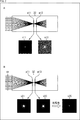
- a in FIG. 4 shows the relationship between the modulation transfer function (MTF) and the defocus amount when the degree of restoration by EDOF signal processing is appropriate.
- MTF modulation transfer function
- FIG. 4 shows the relationship between the modulation transfer function (MTF) and the defocus amount when the degree of restoration by EDOF signal processing is weak.
- weakening the emphasis in EDOF signal processing means that when the optical element is provided and the restoration process is performed by EDOF signal processing, the modulation transfer function (MTF) at the in-focus position is compared with the case without the optical element. ) Is allowed to be small.
- C in FIG. 4 shows the relationship between the modulation transfer function (MTF) and the defocus amount when the degree of restoration by EDOF signal processing is strong.
- MTF modulation transfer function
- a filter that corrects the modulation transfer function (MTF) such as a deconvolution filter
- MTF modulation transfer function
- which coefficient is changed (raised / lowered) is arbitrary, and may be changed relative to, for example, the modulation transfer function (MTF) of the focusing position when the EDOF signal processing is not performed.
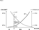
- the horizontal axis represents the degree of restoration processing. Assuming that the center of the horizontal axis (the intersection of the MTF curve and the noise curve) is appropriate, the degree of restoration processing becomes weaker toward the left side and the degree of restoration processing becomes weaker toward the right side based on the degree of this appropriate restoration processing. It shows that the degree becomes stronger.
- the vertical axis on the left side shows the modulation transfer function (MTF) of the focusing position
- MTF curve shows the modulation transfer function (MTF) of the focusing position increases as the degree of restoration processing increases.
- MTF modulation transfer function
- the modulation transfer function (MTF) of the in-focus position decreases as the intensity of the restoration process decreases.
- the vertical axis on the right side shows less noise, and as the noise curve shows, the noise increases as the degree of restoration processing increases, and the degree of restoration processing decreases. The noise becomes smaller.
- the relationship with the noise reduction rate can be tabulated in advance in a presumed use case. Then, by referring to the table, a size that weakens the degree of restoration processing may be selected.
- the noise amount may be measured from the image acquired by the endoscope 14 and the degree of restoration processing may be weakened until the desired noise amount is reached.
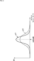
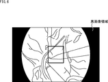
- the amount of noise can be measured from the brightness change of the black image region (mask region, mechanical eclipse region) in which the subject is not captured. it can.
- the medical image processing system 11 may analyze the brightness, edge strength, noise amount, etc. from the image being captured and dynamically switch the degree of restoration. Further, the magnitude of weakening the degree of restoration processing can be selected from the degree of compounding with respect to a normal optical image until the EDOF signal processing is turned off.
- the image becomes more blurred by weakening the degree of restoration. Therefore, for the purpose of complementing this, another image such as edge enhancement, contrast enhancement, gamma correction, etc. Processing can be combined and applied.
- the edge information of the normal light image may be applied to the special light captured image to perform image processing for emphasizing the edge.
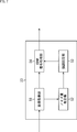
- FIG. 7 is a block diagram showing a configuration example of a signal processing device 23 that realizes special light observation with lower noise.
- the signal processing device 23 includes an image acquisition unit 51, a noise amount estimation unit 52, an emphasis setting unit 53, and an EDOF signal processing unit 54.
- the image acquisition unit 51 irradiates the observation target with the normal light image captured by the image pickup element of the camera head 32 and the special light by the light source device 21 during the period when the normal light is irradiated to the observation target by the light source device 21. During this period, a special light image captured by the image pickup element of the camera head 32 is acquired.
- the noise amount estimation unit 52 determines the brightness change of the black image region (mask region, mechanical eclipse region) in which the subject is not captured in the normal light image acquired by the image acquisition unit 51. Estimate the amount of noise.
- the emphasis setting unit 53 sets the emphasis level in the EDOF signal processing for the special light image to the EDOF signal processing unit 54 according to the noise amount estimated by the noise amount estimation unit 52.
- the emphasis setting unit 53 is preset with a predetermined predetermined value for setting so as to weaken the degree of emphasis. Then, the emphasis setting unit 53 sets the EDOF signal processing unit 54 to perform the EDOF signal processing with a weak emphasis degree (see B in FIG. 4) when the noise amount is equal to or more than the specified value.
- the emphasis setting unit 53 sets the EDOF signal processing unit 54 to perform EDOF signal processing with an appropriate emphasis degree (see A in FIG. 4) when the noise amount is less than the specified value.
- the emphasis setting unit 53 can set parameters for adjusting the emphasis degree in the EDOF signal processing with respect to the EDOF signal processing unit 54.
- the EDOF signal processing unit 54 performs EDOF signal processing on the normal light image and the special light image according to the setting by the emphasis setting unit 53. Then, the normal optical image and the special optical image that have been subjected to EDOF signal processing by the EDOF signal processing unit 54 are output from the signal processing device 23 and displayed on the display device 12.
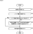
- the process is started when the normal light image and the special light image are captured by the image pickup element of the camera head 32, and in step S11, the image acquisition unit 51 uses the normal light image and the special light image supplied from the camera head 32. To get. Then, the image acquisition unit 51 supplies the normal light image to the noise amount estimation unit 52, and supplies the special light image to the EDOF signal processing unit 54.
- step S12 the noise amount estimation unit 52 generates noise amount in the black image region from the brightness change of the black image region (see FIG. 6) of the normal light image supplied from the image acquisition unit 51 in step S11. To estimate. Then, the noise amount estimation unit 52 supplies the estimated noise amount to the emphasis setting unit 53.
- step S13 the emphasis setting unit 53 determines whether or not the noise amount supplied from the noise amount estimation unit 52 in step S12 is equal to or greater than a preset predetermined value.
- step S13 If the emphasis setting unit 53 determines in step S13 that the noise amount is equal to or greater than the specified value, the process proceeds to step S14.
- step S14 the emphasis setting unit 53 sets the EDOF signal processing unit 54 so as to weaken the degree of emphasis in the EDOF signal processing for the special light image.
- step S14 After the processing of step S14, or when it is determined in step S13 that the noise amount is not equal to or more than the specified value (less than the specified value), the processing proceeds to step S15.
- step S15 the EDOF signal processing unit 54 performs EDOF signal processing on the special optical image supplied from the image acquisition unit 51 in step S11. At this time, the EDOF signal processing unit 54 performs EDOF signal processing with a weak emphasis degree (see B in FIG. 4) when the noise amount is equal to or more than the specified value, and is appropriate when the noise amount is less than the specified value. EDOF signal processing is performed with a high degree of emphasis (see A in FIG. 4).
- step S15 the signal processing is terminated.
- the signal processing device 23 can weaken the degree of emphasis in the EDOF signal processing for the special light image according to the noise estimated from the normal light image. As a result, the medical image processing system 11 can perform special light observation with lower noise.
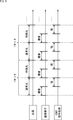
- FIG. 9 shows an example in which a strong EDOF signal processing is applied to a normal light image and a weak special light image is applied to a special light image.
- the period in which the light source device 21 irradiates the normal light and the special light once is set as one set, and this one set is repeated frame-sequentially.
- the CCU 22 controls the image sensor of the camera head 32 so as to take an image during the irradiation period of the normal light and acquire the normal light image, and the EDOF signal processing unit 54 is stronger than the normal light image. Performs EDOF signal processing. After that, the CCU 22 controls the image sensor of the camera head 32 so as to take an image during the irradiation period of the special light and acquire the special light image, and the EDOF signal processing unit 54 is weaker than the normal light image. Performs EDOF signal processing.
- the degree of restoration by the EDOF signal processing performed on the special light image can be weaker than that of the normal light image.
- each image sensor can continuously capture a normal light image and a normal light image.
- FIG. 10 shows an example of a setting screen for setting the degree of restoration by EDOF signal processing for a normal light image and a special light image.
- a slide bar serving as a user interface for setting the degree of restoration by EDOF signal processing for the normal light image and the special light image is displayed below the preview image 62 displayed on the setting screen 61.
- the degree of restoration by EDOF signal processing for the normal light image is set to be weak
- the EDOF signal processing for the normal light image is set.
- the degree of restoration is strongly set.
- moving the slider 64 to the left sets the degree of restoration by EDOF signal processing to the special light image to be weak
- moving the slider 64 to the right sets the EDOF signal to the special light image.
- the degree of restoration by processing is strongly set.
- the degree of restoration of the normal optical image when the degree of restoration of the normal optical image is changed, the degree of restoration of the special optical image can be automatically changed accordingly.
- the degree of restoration of the special light image is always weaker than that of the normal light image.
- the degree of restoration by EDOF signal processing may be selected by operating a button, and various user interfaces can be adopted. For example, using the noise reduction button and the depth of field expansion button, pressing the noise reduction button may weaken the EDOF signal processing, and pressing the depth of field expansion button may enhance the EDOF signal processing. At this time, it is preferable to reduce noise or increase the depth of field while maintaining the relationship that the EDOF signal processing of the special optical image is always weaker than the EDOF signal processing of the normal optical image.
- the medical image processing system 11 displays two special light images side by side, one before the degree of restoration for the special light image is weakened and the other after the degree of restoration for the special light image is weakened, and which is desired is determined. It may be configured so that the user can select it.
- FIG. 11 is a block diagram showing a configuration example of an embodiment of a computer on which a program for executing the above-mentioned series of processes is installed.
- the program can be recorded in advance on the hard disk 105 or ROM 103 as a recording medium built in the computer.
- the program can be stored (recorded) in the removable recording medium 111 driven by the drive 109.
- a removable recording medium 111 can be provided as so-called package software.
- examples of the removable recording medium 111 include a flexible disk, a CD-ROM (Compact Disc Read Only Memory), an MO (Magneto Optical) disk, a DVD (Digital Versatile Disc), a magnetic disk, and a semiconductor memory.
- the program can be downloaded to the computer via a communication network or a broadcasting network and installed on the built-in hard disk 105. That is, for example, the program transfers wirelessly from a download site to a computer via an artificial satellite for digital satellite broadcasting, or transfers to a computer by wire via a network such as LAN (Local Area Network) or the Internet. be able to.
- LAN Local Area Network
- the computer has a built-in CPU (Central Processing Unit) 102, and the input / output interface 110 is connected to the CPU 102 via the bus 101.
- CPU Central Processing Unit
- the CPU 102 executes a program stored in the ROM (Read Only Memory) 103 accordingly. .. Alternatively, the CPU 102 loads the program stored in the hard disk 105 into the RAM (Random Access Memory) 104 and executes it.
- ROM Read Only Memory
- the CPU 102 performs processing according to the above-mentioned flowchart or processing performed according to the above-mentioned block diagram configuration. Then, the CPU 102 outputs the processing result from the output unit 106, transmits it from the communication unit 108, or records it on the hard disk 105, if necessary, via, for example, the input / output interface 110.
- the input unit 107 is composed of a keyboard, a mouse, a microphone, and the like. Further, the output unit 106 is composed of an LCD (Liquid Crystal Display), a speaker, or the like.
- LCD Liquid Crystal Display
- the processing performed by the computer according to the program does not necessarily have to be performed in chronological order in the order described as the flowchart. That is, the processing performed by the computer according to the program also includes processing executed in parallel or individually (for example, parallel processing or processing by an object).
- the program may be processed by one computer (processor) or may be distributed processed by a plurality of computers. Further, the program may be transferred to a distant computer and executed.
- the system means a set of a plurality of components (devices, modules (parts), etc.), and it does not matter whether all the components are in the same housing. Therefore, a plurality of devices housed in separate housings and connected via a network, and a device in which a plurality of modules are housed in one housing are both systems. ..
- the configuration described as one device (or processing unit) may be divided and configured as a plurality of devices (or processing units).
- the configurations described above as a plurality of devices (or processing units) may be collectively configured as one device (or processing unit).
- a configuration other than the above may be added to the configuration of each device (or each processing unit).
- a part of the configuration of one device (or processing unit) may be included in the configuration of another device (or other processing unit). ..
- this technology can have a cloud computing configuration in which one function is shared by a plurality of devices via a network and jointly processed.
- the above-mentioned program can be executed in any device.
- the device may have necessary functions (functional blocks, etc.) so that necessary information can be obtained.
- each step described in the above flowchart can be executed by one device or can be shared and executed by a plurality of devices.
- the plurality of processes included in the one step can be executed by one device or shared by a plurality of devices.
- a plurality of processes included in one step can be executed as processes of a plurality of steps.
- the processes described as a plurality of steps can be collectively executed as one step.
- the processing of the steps for describing the program may be executed in chronological order in the order described in the present specification, or may be called in parallel or called. It may be executed individually at a necessary timing such as time. That is, as long as there is no contradiction, the processing of each step may be executed in an order different from the above-mentioned order. Further, the processing of the step for writing this program may be executed in parallel with the processing of another program, or may be executed in combination with the processing of another program.
- the present technology can also have the following configurations.
- An EDOF signal processing unit that performs EDOF (Extended Depth of Field) signal processing as restoration processing on a special light image acquired by imaging an observation target irradiated with special light. It is provided with a setting unit for setting the restoration degree of the EDOF signal processing with respect to the EDOF signal processing unit.
- the setting unit has the restoration degree in the EDOF signal processing for the special light image rather than the restoration degree in the EDOF signal processing as the restoration processing for the ordinary light image acquired by imaging the observation target irradiated with normal light.
- a signal processing device that sets parameters for the degree of restoration in the EDOF signal processing for the special optical image so as to weaken the degree.
- the setting unit is a parameter for the restoration degree so as to weaken the restoration degree with respect to the special light image when the noise amount is equal to or more than a predetermined specified value.
- the setting unit always weakens the degree of restoration of the special light image in conjunction with the change of the degree of restoration of the normal light image.
- the signal processing apparatus according to any one of (1) to (3) above, which sets a parameter for the degree of restoration.
- the signal processing device EDOF Extended Depth of Field
- the degree of restoration in the EDOF signal processing for the special light image is weaker than the degree of restoration in the EDOF signal processing as the restoration processing for the ordinary light image acquired by imaging the observation target irradiated with normal light.
- To the computer of the signal processing device EDOF (Extended Depth of Field) signal processing is performed as restoration processing on the special light image acquired by imaging the observation target irradiated with special light.
- the degree of restoration in the EDOF signal processing for the special light image is weaker than the degree of restoration in the EDOF signal processing as the restoration processing for the ordinary light image acquired by imaging the observation target irradiated with normal light.
- a program for executing a process of setting parameters for the degree of restoration in the EDOF signal processing for the special optical image is weaker than the degree of restoration in the EDOF signal processing as the restoration processing for the ordinary light image acquired by imaging the observation target irradiated with normal light.
- a light source that irradiates the observation target with special light or normal light
- An imaging unit that captures the observation target irradiated with the special light or the normal light
- An EDOF (Extended Depth of Field) optical system arranged on the optical axis of the light incident on the imaging unit, and It is provided with a signal processing unit that performs signal processing on the image captured by the imaging unit.
- the signal processing unit An EDOF signal processing unit that performs EDOF signal processing as restoration processing on the special light image acquired by imaging the observation target irradiated with the special light. It has a setting unit that sets the restoration degree of the EDOF signal processing with respect to the EDOF signal processing unit.
- the setting unit is described in the EDOF signal processing for the special light image rather than the degree of restoration in the EDOF signal processing as the restoration processing for the normal light image acquired by imaging the observation target irradiated with the normal light.
- a medical image processing system that sets parameters for the degree of restoration in the EDOF signal processing for the special optical image so as to weaken the degree of restoration.
Abstract
Description
図1は、本技術を適用した医療用画像処理システムの一実施の形態の構成例を示すブロック図である。 <Configuration example of medical image processing system>
FIG. 1 is a block diagram showing a configuration example of an embodiment of a medical image processing system to which the present technology is applied.
本実施形態に係る医療用画像処理システムのように、複屈折マスクを利用したEDOF技術を適用する場合における技術的課題について説明する。 <Study on EDOF technology using birefringence mask>
A technical problem in the case of applying the EDOF technique using the birefringence mask as in the medical image processing system according to the present embodiment will be described.

次に、上述した一連の処理(信号処理方法)は、ハードウェアにより行うこともできるし、ソフトウェアにより行うこともできる。一連の処理をソフトウェアによって行う場合には、そのソフトウェアを構成するプログラムが、汎用のコンピュータ等にインストールされる。 <Computer configuration example>
Next, the series of processing (signal processing method) described above can be performed by hardware or software. When a series of processes is performed by software, the programs constituting the software are installed on a general-purpose computer or the like.
なお、本技術は以下のような構成も取ることができる。
(1)
特殊光が照射された観察対象を撮像して取得された特殊光画像に対して、復元処理としてEDOF(Extended Depth of Field)信号処理を施すEDOF信号処理部と、
前記EDOF信号処理の復元度合いを前記EDOF信号処理部に対して設定する設定部と
を備え、
前記設定部は、通常光が照射された前記観察対象を撮像して取得された通常光画像に対する復元処理としてのEDOF信号処理における復元度合いよりも、前記特殊光画像に対する前記EDOF信号処理における前記復元度合いを弱めるように、前記特殊光画像に対する前記EDOF信号処理における前記復元度合い用のパラメータを設定する
信号処理装置。
(2)
前記設定部は、前記通常光画像から推定されるノイズ量に基づいて、前記ノイズ量が所定の規定値以上である場合、前記特殊光画像に対する前記復元度合いを弱めるように前記復元度合い用のパラメータを設定する
上記(1)に記載の信号処理装置。
(3)
前記特殊光画像と前記通常光画像とが、フレームシーケンシャルに撮像される
上記(1)または(2)に記載の信号処理装置。
(4)
前記設定部は、所定のユーザインタフェースを利用して前記通常光画像に対する前記復元度合いが変更される場合、それに連動して常に前記特殊光画像に対する前記復元度合いが弱くなるように、前記通常光画像に対する前記復元度合い用のパラメータを設定する
上記(1)から(3)までのいずれかに記載の信号処理装置。
(5)
信号処理装置が、
特殊光が照射された観察対象を撮像して取得された特殊光画像に対して、復元処理としてEDOF(Extended Depth of Field)信号処理を施すことと、
前記EDOF信号処理の復元度合いを設定することと
を含み、
通常光が照射された前記観察対象を撮像して取得された通常光画像に対する復元処理としてのEDOF信号処理における復元度合いよりも、前記特殊光画像に対する前記EDOF信号処理における前記復元度合いを弱めるように、前記特殊光画像に対する前記EDOF信号処理における前記復元度合い用のパラメータを設定する
信号処理方法。
(6)
信号処理装置のコンピュータに、
特殊光が照射された観察対象を撮像して取得された特殊光画像に対して、復元処理としてEDOF(Extended Depth of Field)信号処理を施すことと、
前記EDOF信号処理の復元度合いを設定することと
を含み、
通常光が照射された前記観察対象を撮像して取得された通常光画像に対する復元処理としてのEDOF信号処理における復元度合いよりも、前記特殊光画像に対する前記EDOF信号処理における前記復元度合いを弱めるように、前記特殊光画像に対する前記EDOF信号処理における前記復元度合い用のパラメータを設定する
処理を実行させるためのプログラム。
(7)
観察対象に対して特殊光または通常光を照射する光源と、
前記特殊光または前記通常光が照射された前記観察対象を撮像する撮像部と、
前記撮像部に入射する光の光軸上に配置されるEDOF(Extended Depth of Field)光学系と、
前記撮像部により撮像された画像に対する信号処理を施す信号処理部と
を備え、
前記信号処理部は、
前記特殊光が照射された前記観察対象を撮像して取得された特殊光画像に対して、復元処理としてEDOF信号処理を施すEDOF信号処理部と、
前記EDOF信号処理の復元度合いを前記EDOF信号処理部に対して設定する設定部と
を有し、
前記設定部は、前記通常光が照射された前記観察対象を撮像して取得された通常光画像に対する復元処理としてのEDOF信号処理における復元度合いよりも、前記特殊光画像に対する前記EDOF信号処理における前記復元度合いを弱めるように、前記特殊光画像に対する前記EDOF信号処理における前記復元度合い用のパラメータを設定する
医療用画像処理システム。 <Example of configuration combination>
The present technology can also have the following configurations.
(1)
An EDOF signal processing unit that performs EDOF (Extended Depth of Field) signal processing as restoration processing on a special light image acquired by imaging an observation target irradiated with special light.
It is provided with a setting unit for setting the restoration degree of the EDOF signal processing with respect to the EDOF signal processing unit.
The setting unit has the restoration degree in the EDOF signal processing for the special light image rather than the restoration degree in the EDOF signal processing as the restoration processing for the ordinary light image acquired by imaging the observation target irradiated with normal light. A signal processing device that sets parameters for the degree of restoration in the EDOF signal processing for the special optical image so as to weaken the degree.
(2)
Based on the noise amount estimated from the normal light image, the setting unit is a parameter for the restoration degree so as to weaken the restoration degree with respect to the special light image when the noise amount is equal to or more than a predetermined specified value. The signal processing device according to (1) above.
(3)
The signal processing device according to (1) or (2) above, wherein the special light image and the normal light image are imaged in a frame sequential manner.
(4)
When the degree of restoration of the normal light image is changed by using a predetermined user interface, the setting unit always weakens the degree of restoration of the special light image in conjunction with the change of the degree of restoration of the normal light image. The signal processing apparatus according to any one of (1) to (3) above, which sets a parameter for the degree of restoration.
(5)
The signal processing device
EDOF (Extended Depth of Field) signal processing is performed as restoration processing on the special light image acquired by imaging the observation target irradiated with special light.
Including setting the degree of restoration of the EDOF signal processing
The degree of restoration in the EDOF signal processing for the special light image is weaker than the degree of restoration in the EDOF signal processing as the restoration processing for the ordinary light image acquired by imaging the observation target irradiated with normal light. , A signal processing method for setting parameters for the degree of restoration in the EDOF signal processing for the special optical image.
(6)
To the computer of the signal processing device
EDOF (Extended Depth of Field) signal processing is performed as restoration processing on the special light image acquired by imaging the observation target irradiated with special light.
Including setting the degree of restoration of the EDOF signal processing
The degree of restoration in the EDOF signal processing for the special light image is weaker than the degree of restoration in the EDOF signal processing as the restoration processing for the ordinary light image acquired by imaging the observation target irradiated with normal light. , A program for executing a process of setting parameters for the degree of restoration in the EDOF signal processing for the special optical image.
(7)
A light source that irradiates the observation target with special light or normal light,
An imaging unit that captures the observation target irradiated with the special light or the normal light, and
An EDOF (Extended Depth of Field) optical system arranged on the optical axis of the light incident on the imaging unit, and
It is provided with a signal processing unit that performs signal processing on the image captured by the imaging unit.
The signal processing unit
An EDOF signal processing unit that performs EDOF signal processing as restoration processing on the special light image acquired by imaging the observation target irradiated with the special light.
It has a setting unit that sets the restoration degree of the EDOF signal processing with respect to the EDOF signal processing unit.
The setting unit is described in the EDOF signal processing for the special light image rather than the degree of restoration in the EDOF signal processing as the restoration processing for the normal light image acquired by imaging the observation target irradiated with the normal light. A medical image processing system that sets parameters for the degree of restoration in the EDOF signal processing for the special optical image so as to weaken the degree of restoration.
Claims (7)
- 特殊光が照射された観察対象を撮像して取得された特殊光画像に対して、復元処理としてEDOF(Extended Depth of Field)信号処理を施すEDOF信号処理部と、
前記EDOF信号処理の復元度合いを前記EDOF信号処理部に対して設定する設定部と
を備え、
前記設定部は、通常光が照射された前記観察対象を撮像して取得された通常光画像に対する復元処理としてのEDOF信号処理における復元度合いよりも、前記特殊光画像に対する前記EDOF信号処理における前記復元度合いを弱めるように、前記特殊光画像に対する前記EDOF信号処理における前記復元度合い用のパラメータを設定する
信号処理装置。 An EDOF signal processing unit that performs EDOF (Extended Depth of Field) signal processing as restoration processing on a special light image acquired by imaging an observation target irradiated with special light.
It is provided with a setting unit for setting the restoration degree of the EDOF signal processing with respect to the EDOF signal processing unit.
The setting unit has the restoration degree in the EDOF signal processing for the special light image rather than the restoration degree in the EDOF signal processing as the restoration processing for the ordinary light image acquired by imaging the observation target irradiated with normal light. A signal processing device that sets parameters for the degree of restoration in the EDOF signal processing for the special optical image so as to weaken the degree. - 前記設定部は、前記通常光画像から推定されるノイズ量に基づいて、前記ノイズ量が所定の規定値以上である場合、前記特殊光画像に対する前記復元度合いを弱めるように前記復元度合い用のパラメータを設定する
請求項1に記載の信号処理装置。 Based on the noise amount estimated from the normal light image, the setting unit is a parameter for the restoration degree so as to weaken the restoration degree with respect to the special light image when the noise amount is equal to or more than a predetermined specified value. The signal processing device according to claim 1. - 前記特殊光画像と前記通常光画像とが、フレームシーケンシャルに撮像される
請求項1に記載の信号処理装置。 The signal processing device according to claim 1, wherein the special optical image and the normal optical image are imaged frame-sequentially. - 前記設定部は、所定のユーザインタフェースを利用して前記通常光画像に対する前記復元度合いが変更される場合、それに連動して常に前記特殊光画像に対する前記復元度合いが弱くなるように、前記通常光画像に対する前記復元度合い用のパラメータを設定する
請求項1に記載の信号処理装置。 When the degree of restoration of the normal light image is changed by using a predetermined user interface, the setting unit always weakens the degree of restoration of the special light image in conjunction with the change of the degree of restoration of the normal light image. The signal processing apparatus according to claim 1, wherein a parameter for the degree of restoration is set. - 信号処理装置が、
特殊光が照射された観察対象を撮像して取得された特殊光画像に対して、復元処理としてEDOF(Extended Depth of Field)信号処理を施すことと、
前記EDOF信号処理の復元度合いを設定することと
を含み、
通常光が照射された前記観察対象を撮像して取得された通常光画像に対する復元処理としてのEDOF信号処理における復元度合いよりも、前記特殊光画像に対する前記EDOF信号処理における前記復元度合いを弱めるように、前記特殊光画像に対する前記EDOF信号処理における前記復元度合い用のパラメータを設定する
信号処理方法。 The signal processing device
EDOF (Extended Depth of Field) signal processing is performed as restoration processing on the special light image acquired by imaging the observation target irradiated with special light.
Including setting the degree of restoration of the EDOF signal processing
The degree of restoration in the EDOF signal processing for the special light image is weaker than the degree of restoration in the EDOF signal processing as the restoration processing for the ordinary light image acquired by imaging the observation target irradiated with normal light. , A signal processing method for setting parameters for the degree of restoration in the EDOF signal processing for the special optical image. - 信号処理装置のコンピュータに、
特殊光が照射された観察対象を撮像して取得された特殊光画像に対して、復元処理としてEDOF(Extended Depth of Field)信号処理を施すことと、
前記EDOF信号処理の復元度合いを設定することと
を含み、
通常光が照射された前記観察対象を撮像して取得された通常光画像に対する復元処理としてのEDOF信号処理における復元度合いよりも、前記特殊光画像に対する前記EDOF信号処理における前記復元度合いを弱めるように、前記特殊光画像に対する前記EDOF信号処理における前記復元度合い用のパラメータを設定する
処理を実行させるためのプログラム。 To the computer of the signal processing device
EDOF (Extended Depth of Field) signal processing is performed as restoration processing on the special light image acquired by imaging the observation target irradiated with special light.
Including setting the degree of restoration of the EDOF signal processing
The degree of restoration in the EDOF signal processing for the special light image is weaker than the degree of restoration in the EDOF signal processing as the restoration processing for the ordinary light image acquired by imaging the observation target irradiated with normal light. , A program for executing a process of setting parameters for the degree of restoration in the EDOF signal processing for the special optical image. - 観察対象に対して特殊光または通常光を照射する光源と、
前記特殊光または前記通常光が照射された前記観察対象を撮像する撮像部と、
前記撮像部に入射する光の光軸上に配置されるEDOF(Extended Depth of Field)光学系と、
前記撮像部により撮像された画像に対する信号処理を施す信号処理部と
を備え、
前記信号処理部は、
前記特殊光が照射された前記観察対象を撮像して取得された特殊光画像に対して、復元処理としてEDOF信号処理を施すEDOF信号処理部と、
前記EDOF信号処理の復元度合いを前記EDOF信号処理部に対して設定する設定部と
を有し、
前記設定部は、前記通常光が照射された前記観察対象を撮像して取得された通常光画像に対する復元処理としてのEDOF信号処理における復元度合いよりも、前記特殊光画像に対する前記EDOF信号処理における前記復元度合いを弱めるように、前記特殊光画像に対する前記EDOF信号処理における前記復元度合い用のパラメータを設定する
医療用画像処理システム。 A light source that irradiates the observation target with special light or normal light,
An imaging unit that captures the observation target irradiated with the special light or the normal light, and
An EDOF (Extended Depth of Field) optical system arranged on the optical axis of the light incident on the imaging unit, and
It is provided with a signal processing unit that performs signal processing on the image captured by the imaging unit.
The signal processing unit
An EDOF signal processing unit that performs EDOF signal processing as restoration processing on the special light image acquired by imaging the observation target irradiated with the special light.
It has a setting unit that sets the restoration degree of the EDOF signal processing with respect to the EDOF signal processing unit.
The setting unit is described in the EDOF signal processing for the special light image rather than the degree of restoration in the EDOF signal processing as the restoration processing for the normal light image acquired by imaging the observation target irradiated with the normal light. A medical image processing system that sets parameters for the degree of restoration in the EDOF signal processing for the special optical image so as to weaken the degree of restoration.
Priority Applications (4)
| Application Number | Priority Date | Filing Date | Title |
|---|---|---|---|
| US17/437,836 US20220151466A1 (en) | 2019-03-28 | 2020-03-23 | Signal processing device, signal processing method, program, and medical image processing system |
| EP20776639.5A EP3925510A4 (en) | 2019-03-28 | 2020-03-23 | Signal processing device, signal processing method, program and medical image processing system |
| CN202080022976.2A CN113645890A (en) | 2019-03-28 | 2020-03-23 | Signal processing device, signal processing method, program, and medical image processing system |
| JP2021509381A JPWO2020196387A1 (en) | 2019-03-28 | 2020-03-23 |
Applications Claiming Priority (2)
| Application Number | Priority Date | Filing Date | Title |
|---|---|---|---|
| JP2019-063268 | 2019-03-28 | ||
| JP2019063268 | 2019-03-28 |
Publications (1)
| Publication Number | Publication Date |
|---|---|
| WO2020196387A1 true WO2020196387A1 (en) | 2020-10-01 |
Family
ID=72610996
Family Applications (1)
| Application Number | Title | Priority Date | Filing Date |
|---|---|---|---|
| PCT/JP2020/012675 WO2020196387A1 (en) | 2019-03-28 | 2020-03-23 | Signal processing device, signal processing method, program and medical image processing system |
Country Status (5)
| Country | Link |
|---|---|
| US (1) | US20220151466A1 (en) |
| EP (1) | EP3925510A4 (en) |
| JP (1) | JPWO2020196387A1 (en) |
| CN (1) | CN113645890A (en) |
| WO (1) | WO2020196387A1 (en) |
Citations (3)
| Publication number | Priority date | Publication date | Assignee | Title |
|---|---|---|---|---|
| JP2017158764A (en) | 2016-03-09 | 2017-09-14 | ソニー株式会社 | Image processing device, image processing method, and recording medium |
| US20190045170A1 (en) * | 2016-02-24 | 2019-02-07 | Sony Corporation | Medical image processing device, system, method, and program |
| WO2019044328A1 (en) * | 2017-08-31 | 2019-03-07 | ソニー株式会社 | Medical image processing device, medical image processing system, and driving method of medical image processing device |
Family Cites Families (5)
| Publication number | Priority date | Publication date | Assignee | Title |
|---|---|---|---|---|
| JP2000005127A (en) * | 1998-01-23 | 2000-01-11 | Olympus Optical Co Ltd | Endoscope system |
| JP3791777B2 (en) * | 2001-12-28 | 2006-06-28 | オリンパス株式会社 | Electronic endoscope |
| JP4054222B2 (en) * | 2002-06-05 | 2008-02-27 | オリンパス株式会社 | Light source device for endoscope device |
| JP4813448B2 (en) * | 2007-11-16 | 2011-11-09 | 富士フイルム株式会社 | IMAGING SYSTEM, IMAGING DEVICE EQUIPPED WITH THIS IMAGING SYSTEM, PORTABLE TERMINAL DEVICE, IN-VEHICLE DEVICE, AND MEDICAL DEVICE |
| WO2014136321A1 (en) * | 2013-03-04 | 2014-09-12 | 富士フイルム株式会社 | Restoration filter generation device and method, image processing device and method, imaging device, program, and recording medium |
-
2020
- 2020-03-23 EP EP20776639.5A patent/EP3925510A4/en active Pending
- 2020-03-23 US US17/437,836 patent/US20220151466A1/en active Pending
- 2020-03-23 WO PCT/JP2020/012675 patent/WO2020196387A1/en active Application Filing
- 2020-03-23 CN CN202080022976.2A patent/CN113645890A/en active Pending
- 2020-03-23 JP JP2021509381A patent/JPWO2020196387A1/ja active Pending
Patent Citations (3)
| Publication number | Priority date | Publication date | Assignee | Title |
|---|---|---|---|---|
| US20190045170A1 (en) * | 2016-02-24 | 2019-02-07 | Sony Corporation | Medical image processing device, system, method, and program |
| JP2017158764A (en) | 2016-03-09 | 2017-09-14 | ソニー株式会社 | Image processing device, image processing method, and recording medium |
| WO2019044328A1 (en) * | 2017-08-31 | 2019-03-07 | ソニー株式会社 | Medical image processing device, medical image processing system, and driving method of medical image processing device |
Non-Patent Citations (1)
| Title |
|---|
| See also references of EP3925510A4 |
Also Published As
| Publication number | Publication date |
|---|---|
| CN113645890A (en) | 2021-11-12 |
| JPWO2020196387A1 (en) | 2020-10-01 |
| US20220151466A1 (en) | 2022-05-19 |
| EP3925510A4 (en) | 2022-04-13 |
| EP3925510A1 (en) | 2021-12-22 |
Similar Documents
| Publication | Publication Date | Title |
|---|---|---|
| US11154179B2 (en) | Medical image processing apparatus, medical image processing system, and driving method of medical image processing apparatus | |
| JP2021094421A (en) | Image processing device, image processing method, and recording medium | |
| US11092795B2 (en) | Systems and methods for coded-aperture-based correction of aberration obtained from Fourier ptychography | |
| JP6167518B2 (en) | Image processing apparatus and method, and program | |
| RU2523965C2 (en) | Image processing device, image capturing device and image processing method | |
| EP2764819A1 (en) | Image processing device, endoscopic device, image processing method and image processing program | |
| WO2012086536A1 (en) | Endoscope device and program | |
| JP2011135563A (en) | Image capturing apparatus, and image processing method | |
| JP2010057619A (en) | Stereoscopic image capturing and displaying system | |
| US10609354B2 (en) | Medical image processing device, system, method, and program | |
| JP2011097992A (en) | Fundus observation apparatus, fundus observation method, and computer program | |
| WO2019073814A1 (en) | Focal point detection device, method therefor, and program | |
| CN110062596B (en) | Automatic focus control device, endoscope device, and method for operating automatic focus control device | |
| US20170132824A1 (en) | Image processing device, image processing method, image processing program, and imaging system | |
| WO2020196387A1 (en) | Signal processing device, signal processing method, program and medical image processing system | |
| JP2023529189A (en) | Method and system for joint demosaicing and spectral feature estimation | |
| WO2020196027A1 (en) | Optical system, endoscope, and medical image processing system | |
| JP6977773B2 (en) | Taking an image of the scene | |
| JP6860000B2 (en) | Medical image processing equipment, systems, methods, programs, image processing systems and medical image processing systems | |
| JP2012516606A (en) | Video data acquisition method and apparatus | |
| WO2021020132A1 (en) | Endoscope operation system, image processing device, and image processing method | |
| WO2018211970A1 (en) | Endoscope | |
| WO2022209218A1 (en) | Medical imaging system, medical imaging device, and control method | |
| JP2020201694A (en) | Image processing device, imaging device, image processing method, program, and storage medium | |
| JP3140813B2 (en) | Endoscope TV system |
Legal Events
| Date | Code | Title | Description |
|---|---|---|---|
| 121 | Ep: the epo has been informed by wipo that ep was designated in this application |
Ref document number: 20776639 Country of ref document: EP Kind code of ref document: A1 |
|
| ENP | Entry into the national phase |
Ref document number: 2021509381 Country of ref document: JP Kind code of ref document: A |
|
| WWE | Wipo information: entry into national phase |
Ref document number: 20776639.5 Country of ref document: EP |
|
| ENP | Entry into the national phase |
Ref document number: 2020776639 Country of ref document: EP Effective date: 20210917 |
|
| NENP | Non-entry into the national phase |
Ref country code: DE |