WO2020196302A1 - 渦流探傷システムおよび渦流探傷方法 - Google Patents
渦流探傷システムおよび渦流探傷方法 Download PDFInfo
- Publication number
- WO2020196302A1 WO2020196302A1 PCT/JP2020/012392 JP2020012392W WO2020196302A1 WO 2020196302 A1 WO2020196302 A1 WO 2020196302A1 JP 2020012392 W JP2020012392 W JP 2020012392W WO 2020196302 A1 WO2020196302 A1 WO 2020196302A1
- Authority
- WO
- WIPO (PCT)
- Prior art keywords
- probe
- flaw detection
- eddy current
- current flaw
- shape
- Prior art date
- Legal status (The legal status is an assumption and is not a legal conclusion. Google has not performed a legal analysis and makes no representation as to the accuracy of the status listed.)
- Ceased
Links
Images

Classifications
-
- G—PHYSICS
- G01—MEASURING; TESTING
- G01N—INVESTIGATING OR ANALYSING MATERIALS BY DETERMINING THEIR CHEMICAL OR PHYSICAL PROPERTIES
- G01N27/00—Investigating or analysing materials by the use of electric, electrochemical, or magnetic means
- G01N27/72—Investigating or analysing materials by the use of electric, electrochemical, or magnetic means by investigating magnetic variables
- G01N27/82—Investigating or analysing materials by the use of electric, electrochemical, or magnetic means by investigating magnetic variables for investigating the presence of flaws
- G01N27/90—Investigating or analysing materials by the use of electric, electrochemical, or magnetic means by investigating magnetic variables for investigating the presence of flaws using eddy currents
Definitions
- the present disclosure relates to eddy current testing systems and eddy current testing methods.
- the present application claims priority based on Japanese Patent Application No. 2019-055453 filed in Japan on March 22, 2019, the contents of which are incorporated herein by reference.
- Patent Document 1 discloses an eddy current flaw detection device including a self-induction type flaw detection coil unit or a mutual induction type flaw detection coil unit.
- a flaw detector coil unit provided on the surface of the object to be measured is connected to the eddy current flaw detector and the load device via a connection cable. That is, this eddy current flaw detector utilizes the fact that the eddy current generated on the surface of the object to be measured based on the magnetic field of the exciting coil changes according to the damage of the object to be measured. That is, the eddy current flaw detector evaluates the damage to the object to be measured by amplifying the minute electromotive force generated in the detection coil by the eddy current with an amplifier.
- the probe is moved at a constant speed while always maintaining an equal distance to the surface of the object to be measured to detect the object to be measured. Therefore, although it is easy to detect an object to be measured having a simple shape, it is difficult to accurately detect an object to be measured having a complicated shape such that a recess is formed on the surface or a curved surface is formed.
- the present disclosure is made in view of the above circumstances, and an object of the present disclosure is to accurately detect an object to be measured having a complicated shape.
- the eddy current flaw detection system moves a eddy current flaw detection probe including a detection coil for detecting an eddy current of an object to be measured, and the eddy current flaw detection probe, and numerically controlled movement controlled by numerical control.
- a mechanism, an eddy current flaw detection probe, and a control device for controlling the numerical control movement mechanism are provided, and the control device acquires the shape of the object to be measured and the numerical value based on the shape of the object to be measured. It is configured to have a position adjusting step of adjusting the position of the eddy current flaw detection probe by inputting a numerical value to the control movement mechanism.
- the eddy current flaw detection system includes a plurality of the eddy current flaw detection probes having different positions or shapes of the detection coils according to the shape of the object to be measured in the first aspect.
- the control device performs a position adjusting step when attaching the eddy current flaw detection probe to the numerically controlled moving mechanism.
- the control device has the shape of the object to be measured and the numerically controlled movement in the position adjustment step.
- the coordinates of the eddy current flaw detection probe obtained from the mechanism are compared.
- the eddy current flaw detection method according to the fifth aspect of the present disclosure includes a shape acquisition step of acquiring the shape of the object to be measured, a first acquisition step of acquiring axial coordinate data of a surface probe, and the first acquisition step.
- the axial coordinate data of the surface probe is compared with the shape of the object to be measured acquired in the shape acquisition step, and the position of the surface probe is adjusted by using the multi-axis movement mechanism of the machining center.
- the eddy current flaw detection method includes, in the fifth aspect, the second acquisition step of attaching the local probe to the machining center and acquiring the axial coordinate data of the local probe, and the second acquisition step.
- a recess flaw detection step of moving the local probe along the recess of the object to be measured by using the multi-axis movement mechanism of the machining center to perform recess flaw detection is further provided.
- the eddy current flaw detection probe is moved by using the numerically controlled movement mechanism, and the position of the eddy current flaw detection probe is adjusted by the control device. Therefore, the eddy current flaw detection probe can be placed at an accurate position, and an object to be measured having a complicated shape can be accurately detected.
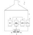
- the eddy current flaw detection system non-destructively inspects the presence or absence and size of damage inside the work W by detecting the eddy current generated on the surface of the work W (inspection target or object to be measured). It is an inspection system to do. As shown in FIG. 1, this eddy current flaw detection system includes a probe A, a machining center 1 (numerical control moving mechanism), a Wi-Fi station 2, a probe magazine 3, an inspection operation unit 4, and an inspection control unit 5 (control device). I have.
- the probe A is an eddy current flaw detection probe according to the present embodiment.
- the probe A is an eddy current flaw detection probe that detects eddy current flaws in the work W based on a control signal (data acquisition control signal) input from the inspection control unit 5. That is, this probe A is an inspection device that generates an eddy current on the surface of the work W and detects the eddy current, and is damaged while moving on the surface of the work W by being mounted on the machining center 1 as shown in the figure. Is detected.
- a plurality of probes A having different shapes are prepared for this probe A according to the shape and size of the work W, and the probe A most suitable for the work W is detachably attached to the machining center 1.
- the probe A most suitable for the work W is detachably attached to the machining center 1.
- a probe A having a different shape from the probe A for inspecting the surface (inner surface) of the hole and the probe A for inspecting the outer surface is used.
- such a probe A includes a probe housing 6, an engaging portion 7, a flaw detection coil 8, a signal conversion unit 9, a battery 10, a communication unit 11, and a Wi-Fi antenna 12 as functional components. I have.
- the probe housing 6 has a cylindrical shape as a whole, with an engaging portion 7 provided at the rear end portion, a flaw detection coil 8 provided at the tip portion, and a Wi-Fi antenna 12 separated from the outer peripheral portion. It is provided.
- a probe housing 6 is a metal housing made of a predetermined metal material such as stainless steel.
- the engaging portion 7 is a columnar portion mounted on the spindle shaft of the machining center 1.
- the engaging portion 7 is a reduced diameter portion provided at the rear end of the probe housing 6, and is detachably held by a holding mechanism inherently provided in the main shaft of the machining center 1. That is, the probe A is integrated with the machining center 1 by holding the engaging portion 7 by the holding mechanism.
- the flaw detection coil 8 is a coil unit in which an exciting coil 8a and a detection coil 8b are incorporated, and has a shape corresponding to the shape and size of the work W.
- the flaw detection coil 8 generates an exciting magnetic field by energizing the exciting coil 8a with an exciting current input from the signal conversion unit 9, and detects an eddy current generated on the surface of the work W by the exciting magnetic field with the detection coil 8b. It is converted into a signal (output signal) and output to the signal conversion unit 9.
- the flaw detection coil 8 When inspecting a work W having a complicated shape, the flaw detection coil 8 sets the shape of the exciting coil 8a to a shape specialized for the surface shape of the work W, that is, a shape capable of appropriately generating an eddy current on the surface of the work W. There is a need to. At the same time, it is necessary to set the shape of the detection coil 8b so that the eddy current can be accurately detected.
- the plurality of probes A described above have different shapes of the flaw detection coil 8 and include, for example, one for a surface for detecting a flat surface of the work W and one for a local portion for detecting a recess of the work W.
- the signal conversion unit 9 is an electronic circuit, outputs the above-mentioned exciting current to the flaw detection coil 8, and converts the detection signal into a digital signal. More specifically, the signal conversion unit 9 generates a sine wave having a frequency corresponding to the work W and supplies it to the exciting coil 8a as an exciting current. Further, the signal conversion unit 9 performs a predetermined analog process (filter process or the like) on the detection signal (analog signal) input from the detection coil 8b, and then samples using the sampling signal having a predetermined cycle (sampling cycle). By doing so, it is converted into a digital detection signal (digital signal).
- a predetermined analog process filter process or the like
- the signal conversion unit 9 converts the digital detection signal into a serial transmission signal in a predetermined format (packet structure) and outputs it to the communication unit 11.
- This serial transmission signal includes a digital detection signal as transmission data, and also includes defect confirmation information for confirming a defect of the digital detection signal, which is a time-series signal, on the receiving side (inspection control unit 5).
- the battery 10 is a rechargeable and dischargeable secondary battery, for example, a small lithium-ion battery having a relatively large capacity.
- the battery 10 discharges the DC power stored by itself and supplies it to the signal conversion unit 9 and the communication unit 11.
- the communication unit 11 converts the serial transmission signal input from the signal conversion unit 9 into a transmission signal conforming to the Wi-Fi standard and outputs it to the Wi-Fi antenna 12. Further, the communication unit 11 extracts a data acquisition control signal from a received signal (a signal conforming to the Wi-Fi standard) input from the Wi-Fi antenna 12 and outputs the data acquisition control signal to the signal conversion unit 9.
- the Wi-Fi antenna 12 converts the transmission signal into radio waves and wirelessly transmits them to the Wi-Fi station 2, receives the radio waves radiated from the Wi-Fi station 2, and transmits the received signal to the communication unit 11. Is output to the signal conversion unit 9 via.
- the communication unit 11 and the Wi-Fi antenna 12 constitute the probe communication unit of the present disclosure.
- the machining center 1 is a moving device that moves the probe A along the surface of the work W based on a control signal (movement control signal) input from the inspection control unit 5. That is, unlike a general machining center, this machining center 1 has a probe A mounted on a spindle shaft instead of a tool, and functions as a moving device that moves the probe A three-dimensionally. As shown in the figure, such a machining center 1 includes a multi-axis moving mechanism 1a (moving mechanism) and an MC control unit 1b.
- the multi-axis movement mechanism 1a includes a spindle (spindle shaft) that holds the probe A detachably, and moves the probe A three-dimensionally. That is, the multi-axis moving mechanism 1a holds and moves the probe A by engaging the main shaft (spindle shaft) with the engaging portion 7 of the probe A.
- a multi-axis moving mechanism 1a is, for example, a combination of an XY stage and another movable axis, and has three to six axes of freedom as a whole.
- Such a multi-axis moving mechanism 1a includes a plurality of motors.
- the MC control unit 1b directly controls the multi-axis movement mechanism 1a based on the movement control signal. That is, the MC control unit 1b exclusively controls the multi-axis movement mechanism 1a, and moves the probe A mounted on the main shaft (spindle shaft) of the multi-axis movement mechanism 1a to the position indicated by the movement control signal.
- the Wi-Fi station 2 is a communication device that performs wireless communication between the probe A and the Wi-Fi standard under the inspection control unit 5.
- the Wi-Fi station 2 receives a transmission signal from the communication unit 11 of the probe A described above via the Wi-Fi antenna 12, and the synchronization data input from the inspection control unit 5 conforms to the Wi-Fi standard. It is converted into a transmission signal and transmitted to the communication unit 11. That is, the Wi-Fi station 2 receives the digital detection signal included in the transmission signal and transmits the data acquisition control signal to the probe A.
- the probe magazine 3 is a storage device that stores a plurality of probes A.
- the probe magazine 3 accommodates probes A that are not used for inspection in a predetermined posture.
- the machining center 1 described above selects and holds one probe A from such a probe magazine 3.
- the inspection operation unit 4 is an operation device that receives an operation instruction of an operator and outputs it to the inspection control unit 5.
- the inspection operation unit 4 designates, for example, an inspection area (three-dimensional area) in the work W as the operation instruction.
- Such an inspection operation unit 4 is, for example, a touch panel or / and a keyboard.
- the inspection control unit 5 is a control device that comprehensively controls the eddy current flaw detection system. That is, the inspection control unit 5 moves the probe A along a predetermined inspection path by outputting a movement control signal regarding the movement of the probe A to the machining center 1. Further, the inspection control unit 5 outputs a data acquisition control signal related to the acquisition of the digital detection signal to the probe A via the Wi-Fi station 2, so that the digital detection signal corresponding to each position of the probe A is sequentially acquired. ..
- the inspection control unit 5 controls the probe A and the machining center 1, the synchronization data is output to the probe A and the machining center 1, so that the sampling cycle of the detection signal in the signal conversion unit 9 and the MC control unit 1b Synchronize with the sampling cycle of probe A position acquisition.
- the synchronization data is included in the data acquisition control signal output by the inspection control unit 5 to the probe A and the movement control signal output by the inspection control unit 5 to the machining center 1.
- the inspection control unit 5 is a computer that comprehensively controls the eddy current flaw detection system as described above by the operator operating the inspection operation unit 4.
- the inspection control unit 5 may be a known computer including a CPU (Central Processing Unit), a RAM (Random Access Memory), a ROM (Read Only Memory), and the like that can perform the above control.
- the details of the control by the inspection control unit 5 may be defined by software that can be arbitrarily changed or updated by the user.
- the inspection control unit 5 is electrically or electronically connected to the MC control unit 1b of the machining center 1, the Wi-Fi station 2, the probe magazine 3, and the inspection operation unit 4, or is wirelessly or It is connected so that signals can be communicated by wire.
- the inspection control unit 5 appropriately controls the MC control unit 1b, the Wi-Fi station 2, the probe magazine 3, and the inspection operation unit 4 of the machining center 1 as needed.
- the inspection control unit 5 outputs a movement control signal to the machining center 1 and a data acquisition control signal to the probe A, so that digital detection signals at a plurality of positions along the inspection path of the work W are detected.
- the MC control unit 1b controls the multi-axis movement mechanism 1a based on the movement control signal to move the probe A (fault detection coil 8) along the inspection path of the work W.
- the machining center 1 sequentially outputs the position data of the probe A (fault detection coil 8) acquired in synchronization with the synchronization signal of the movement control signal to the inspection control unit 5.
- the communication unit 11 receives the data acquisition control signal via the Wi-Fi station 2 and the Wi-Fi antenna 12 and outputs the data acquisition control signal to the signal conversion unit 9. Then, the signal conversion unit 9 sequentially acquires the digital detection signal in synchronization with the synchronization signal of the data acquisition control signal and sequentially outputs the digital detection signal to the communication unit 11.
- the signal conversion unit 9 generates an exciting magnetic field in the work W by outputting the exciting current to the exciting coil 8a of the flaw detection coil 8, and generates an eddy current in the work W. Then, the signal conversion unit 9 sequentially converts the detection signal continuously input from the detection coil 8b of the flaw detection coil 8 into a digital detection signal by sampling with a sampling signal synchronized with the synchronization signal.
- the communication unit 11 sequentially transmits the digital detection signal input from the signal conversion unit 9 to the inspection control unit 5 via the Wi-Fi antenna 12 and the Wi-Fi station 2.
- the inspection control unit 5 sequentially stores the inspection data of each position in the inspection path by associating the position data at the same time with the digital detection signal. That is, as the probe A moves from the start point to the end point of the inspection path, inspection data at a plurality of positions of the work W along the inspection path are acquired.
- an instruction to start flaw detection is input to the inspection operation unit 4 by the operator.
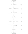
- the inspection control unit 5 acquires the shape of the work W in advance based on the input to the inspection operation unit 4 (step S1: shape acquisition step).
- the inspection operation unit 4 for example, when the inspection operation unit 4 is provided with an input device such as a keyboard key, the dimensions of the work W may be input using the keys.
- the shape of a plurality of types of work W that are frequently used is displayed on the inspection operation unit 4 in a shape like a keyboard key, and the shape of the work W is inspected by the operator pressing a key of the corresponding shape. It may be input to the operation unit 4 and the dimensions of the shape may be input at the same time.
- the probe A for the surface is attached to the machining center 1.
- the inspection control unit 5 acquires and stores the axial coordinate data of the surface probe A and the flaw detection signal from the surface probe A from the MC control unit 1b (step S2: first acquisition step). At this time, the inspection control unit 5 may acquire and store only the axial coordinate data of the surface probe A from the MC control unit 1b. Then, the inspection control unit 5 compares the axial coordinate data of the surface probe A acquired in step S2 with the shape of the work W acquired in step S1 and adjusts the position of the surface probe A (step S3). : First position adjustment step).
- step S3 corresponds to the position adjustment step in this disclosure.
- step S4 surface flaw detection step.
- the surface probe A moves along the surface of the work W by being moved by the multi-axis movement mechanism 1a, and transmits the flaw detection signal of the work W to the inspection control unit 5.
- the inspection control unit 5 acquires and stores the axial coordinate data of the local probe A and the flaw detection signal from the local probe A from the MC control unit 1b (step S5: second acquisition step). At this time, the inspection control unit 5 may acquire and store only the axial coordinate data of the local probe A from the MC control unit 1b.
- the inspection control unit 5 compares the axial coordinate data of the local probe A acquired in step S5 with the shape of the work W acquired in step S1 in the same manner as in step S3, and compares the shape of the work W acquired in step S1 with the local probe A.
- the position is adjusted (step S6: second position adjustment step).
- step S7 concave portion flaw detection step.
- the local probe A moves along the recess of the work W by being moved to the multi-axis movement mechanism 1a, and transmits the flaw detection signal of the work W to the inspection control unit 5.
- the inspection control unit 5 performs a position adjusting step when the probe A is attached. That is, when the probe A is attached, the position of the probe A is adjusted appropriately, and then the probe A is moved by the machining center. Therefore, it is possible to detect a work W having a complicated shape by the probe A at an accurate position and at a constant speed.
- a plurality of probes A are provided, and each probe A is replaced for each shape of the work W. Therefore, it is possible to perform flaw detection by the optimum probe A along each surface of the work W, and this also enables flaw detection of the work W having a complicated shape by the probe A at an accurate position and at a constant speed. It is possible.
- the inspection control unit 5 performs a position adjusting step each time when each probe A is attached. Therefore, every time the probe A is replaced, the probe A can be guided to an accurate position.
- the position of the probe A is adjusted by comparing the axis coordinate data with the shape of the work W. Therefore, this also allows the probe A to be guided to the correct position.
- an eddy current flaw detection system may include only one probe A.
- the Wi-Fi station 2 is adopted as the communication device, but the present disclosure is not limited to this.
- a communication device based on a communication method other than Wi-Fi (registered trademark) may be adopted.
- the probe communication unit that is, the communication unit 11 and the Wi-Fi antenna 12, need to comply with the communication method of the communication device.
- the eddy current flaw detection probe can be placed at an accurate position, and an object to be measured having a complicated shape can be accurately detected.
- a probe eddy current flaw detection probe, surface probe, local probe
- 1 Machining center number of Machining center
- 1a Multi-axis movement mechanism 1b
- MC control unit 2
- Wi-Fi station 3
- Inspection operation unit 5
- Inspection control unit (control device) 6
- Probe housing 7
- Engagement part 8 Damage detection coil 8a
- Excitation coil 8b
- Detection coil 9
- Signal conversion part 10
- Battery 11 Communication part 12 Wi-Fi antenna
Landscapes
- Chemical & Material Sciences (AREA)
- Chemical Kinetics & Catalysis (AREA)
- Electrochemistry (AREA)
- Physics & Mathematics (AREA)
- Health & Medical Sciences (AREA)
- Life Sciences & Earth Sciences (AREA)
- Analytical Chemistry (AREA)
- Biochemistry (AREA)
- General Health & Medical Sciences (AREA)
- General Physics & Mathematics (AREA)
- Immunology (AREA)
- Pathology (AREA)
- Investigating Or Analyzing Materials By The Use Of Magnetic Means (AREA)
Abstract
被測定物(W)の渦電流を検出する検出コイル(8b)を備える渦流探傷プローブ(A)と、前記渦流探傷プローブ(A)を移動させると共に、数値制御により制御される数値制御移動機構(1)と、前記渦流探傷プローブ(A)及び前記数値制御移動機構(1)を制御する制御装置(5)とを備え、前記制御装置(5)は、前記被測定物(W)の形状を取得すると共に、前記被測定物の前記形状に基づいて前記数値制御移動機構(1)に数値を入力することにより、前記渦流探傷プローブ(A)の位置を調整する位置調整工程(S3)を有する渦流探傷システム。
Description
本開示は、渦流探傷システムおよび渦流探傷方法に関する。
本願は、2019年3月22日に日本国に出願された特願2019-055435号に基づき優先権を主張し、その内容をここに援用する。
本願は、2019年3月22日に日本国に出願された特願2019-055435号に基づき優先権を主張し、その内容をここに援用する。
下記特許文献1には、自己誘導型の探傷コイルユニットあるいは相互誘導型の探傷コイルユニットを備える渦流探傷装置が開示されている。この渦流探傷装置は、特許文献1の第1図等に示されているように、被測定物の表面に設けられた探傷コイルユニットを接続ケーブルを介して渦流探傷器及び負荷装置に接続する。すなわち、この渦流探傷装置は、励磁コイルの磁界に基づいて被測定物の表面に発生する渦電流が被測定物の損傷に応じて変化することを利用する。つまり、渦流探傷装置は、渦電流によって検知コイルに発生する微小な起電力をアンプで増幅することにより被測定物の損傷を評価する。
このような渦流探傷装置では、被測定物の表面に対して常に等しい距離を保ちつつプローブを等速移動させることで、被測定物の探傷を行う。したがって、単純形状の被測定物に対しての探傷は容易であるが、表面に凹部が形成されていたり曲面状とされるような複雑形状の被測定物の正確な探傷は困難である。
本開示は、上述した事情に鑑みてなされ、複雑形状の被測定物を正確に探傷することを目的とする。
本開示の第1の態様に係る渦流探傷システムは、被測定物の渦電流を検出する検出コイルを備える渦流探傷プローブと、前記渦流探傷プローブを移動させると共に、数値制御により制御される数値制御移動機構と、前記渦流探傷プローブ及び前記数値制御移動機構を制御する制御装置とを備え、前記制御装置は、前記被測定物の形状を取得すると共に、前記被測定物の前記形状に基づいて前記数値制御移動機構に数値を入力することにより、前記渦流探傷プローブの位置を調整する位置調整工程を有するように構成されている。
本開示の第2の態様に係る渦流探傷システムは、上記第1の態様において、前記被測定物の前記形状に合わせて、前記検出コイルの位置または形状の異なる複数の前記渦流探傷プローブを備える。
本開示の第3の態様に係る渦流探傷システムは、上記第2の態様において、前記制御装置は、前記渦流探傷プローブを前記数値制御移動機構に対して取り付ける際に位置調整工程を行う。
本開示の第4の態様に係る渦流探傷システムは、上記第1~3のいずれかの態様において、前記制御装置は、前記位置調整工程において、前記被測定物の前記形状と、前記数値制御移動機構から取得した前記渦流探傷プローブの座標とを比較する。
本開示の第5の態様に係る渦流探傷方法は、被測定物の形状を取得する形状取得工程と、表面用プローブの軸座標データを取得する第1取得工程と、前記第1取得工程で取得した前記表面用プローブの前記軸座標データと、前記形状取得工程で取得した前記被測定物の前記形状とを比較して前記表面用プローブの位置をマシニングセンタの多軸移動機構を用いて調整する第1位置調整工程と、前記マシニングセンタの前記多軸移動機構を用いて前記表面用プローブを前記被測定物の表面に沿って移動して前記被測定物の表面を探傷する表面探傷工程とを備える。
本開示の第6の態様に係る渦流探傷方法は、上記第5の態様において、前記マシニングセンタに局部用プローブを取り付け、前記局部用プローブの軸座標データを取得する第2取得工程と、前記第2取得工程で取得した前記局部用プローブの前記軸座標データと、前記形状取得工程で取得した前記被測定物の形状とを比較して、前記局部用プローブの位置を調整する第2位置調整工程と、前記マシニングセンタの前記多軸移動機構を用いて前記局部用プローブを前記被測定物の凹部に沿って移動して凹部探傷を行う凹部探傷工程と、をさらに備える。
本開示の第5の態様に係る渦流探傷方法は、被測定物の形状を取得する形状取得工程と、表面用プローブの軸座標データを取得する第1取得工程と、前記第1取得工程で取得した前記表面用プローブの前記軸座標データと、前記形状取得工程で取得した前記被測定物の前記形状とを比較して前記表面用プローブの位置をマシニングセンタの多軸移動機構を用いて調整する第1位置調整工程と、前記マシニングセンタの前記多軸移動機構を用いて前記表面用プローブを前記被測定物の表面に沿って移動して前記被測定物の表面を探傷する表面探傷工程とを備える。
本開示の第6の態様に係る渦流探傷方法は、上記第5の態様において、前記マシニングセンタに局部用プローブを取り付け、前記局部用プローブの軸座標データを取得する第2取得工程と、前記第2取得工程で取得した前記局部用プローブの前記軸座標データと、前記形状取得工程で取得した前記被測定物の形状とを比較して、前記局部用プローブの位置を調整する第2位置調整工程と、前記マシニングセンタの前記多軸移動機構を用いて前記局部用プローブを前記被測定物の凹部に沿って移動して凹部探傷を行う凹部探傷工程と、をさらに備える。
本開示によれば、数値制御移動機構を用いて渦流探傷プローブを移動させると共に、制御装置により渦流探傷プローブの位置を調整する。したがって、渦流探傷プローブを正確な位置に配置することができ、複雑形状の被測定物を正確に探傷することができる。
以下、図面を参照して、本開示の一実施形態について説明する。
本実施形態に係る渦流探傷システムは、ワークW(検査対象、又は被測定物)の表面に発生する渦電流を検出することにより、ワークWの内部における損傷の有無や大きさ等を非破壊検査する検査システムである。この渦流探傷システムは、図1に示すように、プローブA、マシニングセンタ1(数値制御移動機構)、Wi-Fiステーション2、プローブ・マガジン3、検査操作部4及び検査制御部5(制御装置)を備えている。なお、上記プローブAは、本実施形態に係る渦流探傷プローブである。
本実施形態に係る渦流探傷システムは、ワークW(検査対象、又は被測定物)の表面に発生する渦電流を検出することにより、ワークWの内部における損傷の有無や大きさ等を非破壊検査する検査システムである。この渦流探傷システムは、図1に示すように、プローブA、マシニングセンタ1(数値制御移動機構)、Wi-Fiステーション2、プローブ・マガジン3、検査操作部4及び検査制御部5(制御装置)を備えている。なお、上記プローブAは、本実施形態に係る渦流探傷プローブである。
プローブAは、検査制御部5から入力される制御信号(データ取得制御信号)に基づいてワークWを渦流探傷する渦流探傷プローブである。すなわち、このプローブAは、ワークWの表面に渦電流を発生させると共に当該渦電流を検出する検査装置であり、図示するようにマシニングセンタ1に装着されることによりワークWの表面を移動しつつ損傷を検出する。
このプローブAは、ワークWの形状や大きさ等に応じて異なる形状のプローブAが複数用意されており、ワークWに最適なプローブAがマシニングセンタ1に着脱自在に装着される。例えば穴が形成されたワークWの場合、穴の表面(内表面)を検査するプローブAと外表面を検査するプローブAとは異なる形状のプローブAが用いられる。
このようなプローブAは、図2に示すように、プローブ筐体6、係合部7、探傷コイル8、信号変換部9、電池10、通信部11及びWi-Fiアンテナ12を機能構成要素として備えている。
プローブ筐体6は、全体として円筒状であり、後端部に係合部7が設けられ、先端部に探傷コイル8が設けられ、また外周部にはWi-Fiアンテナ12が離間した状態で設けられている。このようなプローブ筐体6は、所定の金属材料、例えばステンレス等から形成された金属筐体である。
係合部7は、マシニングセンタ1の主軸(スピンドル軸)に装着される円柱状部位である。この係合部7は、プローブ筐体6の後端に設けられた縮径部であり、マシニングセンタ1の主軸が本来的に備えている保持機構によって着脱自在に保持される。すなわち、係合部7が保持機構によって保持されることによって、プローブAはマシニングセンタ1と一体化する。
探傷コイル8は、励磁コイル8aと検出コイル8bとが組み込まれたコイルユニットであり、ワークWの形状や大きさ等に応じた形状を有する。この探傷コイル8は、信号変換部9から入力される励磁電流を励磁コイル8aに通電することにより励磁磁界を発生させ、また励磁磁界によってワークWの表面に発生する渦電流を検出コイル8bで検出信号(出力信号)に変換して信号変換部9に出力する。
複雑な形状のワークWを検査する場合、探傷コイル8は、ワークWの表面形状に特化した形状、つまりワークWの表面に渦電流を適切に発生させ得る形状に励磁コイル8aの形状を設定する必要がある。同時に、渦電流を的確に検出し得る形状に検出コイル8bの形状を設定する必要がある。上述した複数のプローブAは、探傷コイル8の形状が互いに異なっており、例えば、ワークWの平坦な表面を探傷する表面用と、ワークWの凹部を探傷する局部用とがある。
信号変換部9は、電子回路であり、上述した励磁電流を探傷コイル8に出力すると共に検出信号をデジタル信号に変換する。より詳細には、信号変換部9は、ワークWに応じた周波数の正弦波を生成し励磁電流として励磁コイル8aに供給する。また、信号変換部9は、検出コイル8bから入力される検出信号(アナログ信号)に所定のアナログ処理(フィルタ処理等)を施した後に、所定周期(サンプリング周期)のサンプリング信号を用いてサンプリングすることによりデジタル検出信号(デジタル信号)に変換する。
この信号変換部9は、上記デジタル検出信号を所定フォーマット(パケット構造)のシリアル伝送信号に変換して通信部11に出力する。このシリアル伝送信号は、デジタル検出信号を伝送データとして含むと共に、時系列信号であるデジタル検出信号の欠損を受信側(検査制御部5)で確認するための欠損確認情報を含んでいる。
電池10は、充放電可能な二次電池であり、例えば小型かつ容量が比較的大きなリチウムイオン電池である。この電池10は、自らが蓄電した直流電力を放電して信号変換部9及び通信部11に供給する。
通信部11は、信号変換部9から入力されるシリアル伝送信号をWi-Fi規格に準拠した送信信号に変換してWi-Fiアンテナ12に出力する。また、この通信部11は、Wi-Fiアンテナ12から入力される受信信号(Wi-Fi規格に準拠した信号)からデータ取得制御信号を抽出して信号変換部9に出力する。Wi-Fiアンテナ12は、上記送信信号を電波に変換してWi-Fiステーション2に向けて無線送信すると共に、Wi-Fiステーション2から放射された電波を受信して受信信号を、通信部11を介して信号変換部9に出力する。
なお、通信部11及びWi-Fiアンテナ12は、本開示のプローブ通信部を構成している。
なお、通信部11及びWi-Fiアンテナ12は、本開示のプローブ通信部を構成している。
マシニングセンタ1は、検査制御部5から入力される制御信号(移動制御信号)に基づいてプローブAをワークWの表面に沿って移動させる移動装置である。すなわち、このマシニングセンタ1は、一般的なマシニングセンタとは異なり、工具に代えてプローブAが主軸(スピンドル軸)に装着され、プローブAを三次元的に移動させる移動装置として機能する。このようなマシニングセンタ1は、図示するように多軸移動機構1a(移動機構)とMC制御部1bとを備える。
多軸移動機構1aは、プローブAを着脱自在に保持する主軸(スピンドル軸)を備え、プローブAを三次元的に移動させる。すなわち、多軸移動機構1aは、主軸(スピンドル軸)をプローブAの係合部7に係合させることによりプローブAを保持かつ移動させる。
このような多軸移動機構1aは、例えばX-Yステージに他の可動軸を組み合わせたものであり、全体として三軸~六軸の自由度を有する。このような多軸移動機構1aは、複数のモータを備える。
このような多軸移動機構1aは、例えばX-Yステージに他の可動軸を組み合わせたものであり、全体として三軸~六軸の自由度を有する。このような多軸移動機構1aは、複数のモータを備える。
MC制御部1bは、上記移動制御信号に基づいて多軸移動機構1aを直接制御する。すなわち、MC制御部1bは、多軸移動機構1aを専ら制御対象とし、多軸移動機構1aの主軸(スピンドル軸)に装着されたプローブAを移動制御信号で指示された位置に移動させる。
Wi-Fiステーション2は、検査制御部5の下でプローブAとWi-Fi規格に準拠した無線通信を行う通信装置である。このWi-Fiステーション2は、上述したプローブAの通信部11からWi-Fiアンテナ12を介して送信信号を受信し、また検査制御部5から入力された同期データをWi-Fi規格に準拠した送信信号に変換して通信部11宛に送信する。すなわち、Wi-Fiステーション2は、送信信号に含まれるデジタル検出信号を受信すると共に、データ取得制御信号をプローブAに送信する。
プローブ・マガジン3は、複数のプローブAを収容する収容装置である。このプローブ・マガジン3は、検査に使用しないプローブAを所定姿勢で配列した状態で収容する。上述したマシニングセンタ1は、このようなプローブ・マガジン3から1つのプローブAを選択して保持する。
検査操作部4は、作業者の操作指示を受け付けて検査制御部5に出力する操作装置である。この検査操作部4は、上記操作指示として、例えばワークWにおける検査領域(三次元領域)を指定する。このような検査操作部4は、例えばタッチパネルあるいは/及びキーボードである。
検査制御部5は、渦流探傷システムを統括的に制御する制御装置である。すなわち、検査制御部5は、マシニングセンタ1に対してプローブAの移動に関する移動制御信号を出力することによりプローブAを所定の検査経路に沿って移動させる。また、検査制御部5は、Wi-Fiステーション2を介してプローブAにデジタル検出信号の取得に関するデータ取得制御信号を出力することにより、プローブAの各位置に応じたデジタル検出信号を順次取得させる。
また、検査制御部5による、このようなプローブA及びマシニングセンタ1の制御に際して、同期データをプローブA及びマシニングセンタ1に出力することにより、信号変換部9における検出信号のサンプリング周期とMC制御部1bにおけるプローブAの位置取得のサンプリング周期とを同期させる。なお、上記同期データは、検査制御部5がプローブAに出力するデータ取得制御信号及び検査制御部5がマシニングセンタ1に出力する移動制御信号に含まれる。ここで、検査制御部5は、作業者が検査操作部4を操作することにより、上記のように渦流探傷システムを統括的に制御するコンピュータである。即ち、検査制御部5は、上記のような制御を実施できるようなCPU(Central Processing Unit),RAM(Random Access Memory),ROM(Read Only Memory)等を含む公知の計算機でもよい。検査制御部5による制御の詳細は、ユーザーが任意に変更または更新可能なソフトウェアにより定義されても良い。図1に示すように、検査制御部5は、マシニングセンタ1のMC制御部1b、Wi-Fiステーション2、プローブ・マガジン3、検査操作部4と電気的あるいは電子的に接続され、或いは、無線若しくは有線により信号を通信可能なように接続されている。検査制御部5は、必要に応じてマシニングセンタ1のMC制御部1b、Wi-Fiステーション2、プローブ・マガジン3、検査操作部4を適宜制御する。
次に、本実施形態に係るプローブA(渦流探傷プローブ)及び渦流探傷システムの動作について詳しく説明する。
この渦流探傷システムでは、検査制御部5がマシニングセンタ1に移動制御信号を出力し、かつ、プローブAにデータ取得制御信号を出力することにより、ワークWの検査経路に沿った複数位置のデジタル検出信号が順次取得される。すなわち、マシニングセンタ1は、MC制御部1bが移動制御信号に基づいて多軸移動機構1aを制御することによりプローブA(探傷コイル8)をワークWの検査経路に沿って移動させる。また、マシニングセンタ1は、移動制御信号の同期信号に同期して取得したプローブA(探傷コイル8)の位置データを検査制御部5に順次出力する。
一方、プローブAでは、通信部11は、Wi-Fiステーション2及びWi-Fiアンテナ12を介してデータ取得制御信号を受信して信号変換部9に出力する。そして、信号変換部9は、データ取得制御信号の同期信号に同期してデジタル検出信号を順次取得して通信部11に順次出力する。
すなわち、信号変換部9は、励磁電流を探傷コイル8の励磁コイル8aに出力することによってワークWに励磁磁界を発生させ、ワークWに渦電流を発生させる。そして、信号変換部9は、探傷コイル8の検出コイル8bから連続的に入力される検出信号を同期信号に同期したサンプリング信号でサンプリングすることによりデジタル検出信号に順次変換する。
そして、通信部11は、信号変換部9から入力されるデジタル検出信号をWi-Fiアンテナ12及びWi-Fiステーション2を介して検査制御部5に順次送信する。そして、検査制御部5は、同一時刻の位置データとデジタル検出信号とを各々関連付けることにより、検査経路における各位置の検査データとして順次記憶する。すなわち、プローブAが検査経路の始点から終点まで移動することによって、検査経路に沿ったワークWの複数位置の検査データが取得される。
続いて、検査制御部5及びプローブAの動作について、図3を参照して説明する。
まず、検査操作部4に、作業者により探傷開始の指示が入力される。検査制御部5は、検査操作部4への入力に基づいて、ワークWの形状を予め取得する(ステップS1:形状取得工程)。検査操作部4への入力の例として、例えば、検査操作部4にキーボードのキーのような入力装置が備わっている場合は、キーを使用してワークWの寸法を入力しても良い。或いは、検査操作部4に使用頻度の高い複数種類のワークWの形状がキーボードのキーのような形状で表示されていて、作業者が該当する形状のキーを押すことでワークWの形状が検査操作部4に入力され、同時に形状の寸法を入力しても良い。このとき、マシニングセンタ1に、表面用のプローブAが取り付けられる。
まず、検査操作部4に、作業者により探傷開始の指示が入力される。検査制御部5は、検査操作部4への入力に基づいて、ワークWの形状を予め取得する(ステップS1:形状取得工程)。検査操作部4への入力の例として、例えば、検査操作部4にキーボードのキーのような入力装置が備わっている場合は、キーを使用してワークWの寸法を入力しても良い。或いは、検査操作部4に使用頻度の高い複数種類のワークWの形状がキーボードのキーのような形状で表示されていて、作業者が該当する形状のキーを押すことでワークWの形状が検査操作部4に入力され、同時に形状の寸法を入力しても良い。このとき、マシニングセンタ1に、表面用のプローブAが取り付けられる。
そして、検査制御部5は、MC制御部1bより、表面用プローブAの軸座標データと、表面用プローブAからの探傷信号とを取得し、記憶する(ステップS2:第1取得工程)。この際、検査制御部5は、MC制御部1bより、表面用プローブAの軸座標データのみを取得して記憶しても良い。そして、検査制御部5は、ステップS2で取得した表面用プローブAの軸座標データと、ステップS1で取得したワークWの形状とを比較して、表面用プローブAの位置を調整する(ステップS3:第1位置調整工程)。具体的には、検査制御部5は、表面用プローブAの軸座標データに基づき、調整定数(数値)を算出し、調整定数を用いて多軸移動機構1aにより表面用プローブAを移動させることで、表面用プローブAの位置をワークWに対して最適な位置へと変更する。なお、ステップS3は、本開示における位置調整工程に相当する。
さらに、検査制御部5は、表面用プローブAの表面探傷を指示する(ステップS4:表面探傷工程)。
これにより、表面用プローブAは、多軸移動機構1aに移動されることで、ワークWの表面に沿って移動し、ワークWの探傷信号を検査制御部5へと送信する。
これにより、表面用プローブAは、多軸移動機構1aに移動されることで、ワークWの表面に沿って移動し、ワークWの探傷信号を検査制御部5へと送信する。
そして、ワークWの表面の探傷が完了すると、続いて、ワークWの凹部における探傷を行う。このとき、マシニングセンタ1に、表面用プローブAに代わって局部用のプローブAが取り付けられる。検査制御部5は、MC制御部1bより、局部用プローブAの軸座標データと、局部用プローブAからの探傷信号とを取得し、記憶する(ステップS5:第2取得工程)。この際、検査制御部5は、MC制御部1bより、局部用プローブAの軸座標データのみを取得して記憶しても良い。そして、検査制御部5は、上記ステップS3と同様に、ステップS5で取得した局部用プローブAの軸座標データと、ステップS1で取得したワークWの形状とを比較して、局部用プローブAの位置を調整する(ステップS6:第2位置調整工程)。
そして、検査制御部5は、局部用プローブAの凹部探傷を指示する(ステップS7:凹部探傷工程)。
これにより、局部用プローブAは、多軸移動機構1aに移動されることで、ワークWの凹部に沿って移動し、ワークWの探傷信号を検査制御部5へと送信する。
これにより、局部用プローブAは、多軸移動機構1aに移動されることで、ワークWの凹部に沿って移動し、ワークWの探傷信号を検査制御部5へと送信する。
本実施形態によれば、検査制御部5は、プローブAが取り付けられる際に、位置調整工程を行う。つまり、プローブA取り付け時において、プローブAの位置を適切に調整した上で、マシニングセンタによりプローブAを移動させる。したがって、プローブAによる複雑形状のワークWの探傷を、正確な位置かつ等速で実施することが可能である。
また、本実施形態によれば、複数のプローブAを有しており、各プローブAをワークWの形状ごとに取り替えている。したがって、ワークWの各面に沿って最適なプローブAにより探傷を行うことが可能であり、これによってもプローブAによる複雑形状のワークWの探傷を、正確な位置かつ等速で実施することが可能である。
また、本実施形態によれば、検査制御部5は、各プローブAを取り付ける際に、毎回位置調整工程を行う。したがって、プローブAを取り替えた際に、毎回プローブAを正確な位置へと案内することができる。
また、本実施形態においては、軸座標データとワークWの形状とを比較することで、プローブAの位置を調整している。したがって、これによっても、プローブAを正確な位置へと案内することができる。
なお、本開示は上記実施形態に限定されず、例えば以下のような変形例が考えられる。
(1)上記実施形態においては、プローブAを複数有し、プローブAを取り替えて使用するが、本開示はこれに限定されない。例えば、渦流探傷システムは、1つのプローブAのみを備えてもよい。
(1)上記実施形態においては、プローブAを複数有し、プローブAを取り替えて使用するが、本開示はこれに限定されない。例えば、渦流探傷システムは、1つのプローブAのみを備えてもよい。
(2)上記実施形態では、通信装置としてWi-Fiステーション2を採用したが、本開示はこれに限定されない。Wi-Fi(登録商標)以外の通信方式に基づく通信装置を採用してもよい。なお、この場合には、プローブ通信部つまり通信部11及びWi-Fiアンテナ12については、通信装置の通信方式に準拠している必要がある。
本開示の渦流探傷システムによれば、渦流探傷プローブを正確な位置に配置することができ、複雑形状の被測定物を正確に探傷することができる。
A プローブ(渦流探傷プローブ、表面用プローブ、局部用プローブ)
1 マシニングセンタ(数値制御移動機構)
1a 多軸移動機構
1b MC制御部
2 Wi-Fiステーション
3 プローブ・マガジン
4 検査操作部
5 検査制御部(制御装置)
6 プローブ筐体
7 係合部
8 探傷コイル
8a 励磁コイル
8b 検出コイル
9 信号変換部
10 電池
11 通信部
12 Wi-Fiアンテナ
1 マシニングセンタ(数値制御移動機構)
1a 多軸移動機構
1b MC制御部
2 Wi-Fiステーション
3 プローブ・マガジン
4 検査操作部
5 検査制御部(制御装置)
6 プローブ筐体
7 係合部
8 探傷コイル
8a 励磁コイル
8b 検出コイル
9 信号変換部
10 電池
11 通信部
12 Wi-Fiアンテナ
Claims (6)
- 被測定物の渦電流を検出する検出コイルを備える渦流探傷プローブと、
前記渦流探傷プローブを移動させると共に、数値制御により制御される数値制御移動機構と、
前記渦流探傷プローブ及び前記数値制御移動機構を制御する制御装置と
を備え、
前記制御装置は、前記被測定物の形状を取得すると共に、前記被測定物の前記形状に基づいて前記数値制御移動機構に数値を入力することにより、前記渦流探傷プローブの位置を調整する位置調整工程を有する
渦流探傷システム。 - 前記被測定物の前記形状に合わせて、前記検出コイルの位置または形状の異なる複数の前記渦流探傷プローブを備える請求項1に記載の渦流探傷システム。
- 前記制御装置は、前記渦流探傷プローブを前記数値制御移動機構に対して取り付ける際に位置調整工程を行う請求項2に記載の渦流探傷システム。
- 前記制御装置は、前記位置調整工程において、前記被測定物の前記形状と、前記数値制御移動機構から取得した前記渦流探傷プローブの座標とを比較する請求項1~3のいずれか一項に記載の渦流探傷システム。
- 被測定物の形状を取得する、形状取得工程と、
表面用プローブの軸座標データを取得する第1取得工程と、
前記第1取得工程で取得した前記表面用プローブの前記軸座標データと、前記形状取得工程で取得した前記被測定物の前記形状とを比較して前記表面用プローブの位置をマシニングングセンタの多軸移動機構を用いて調整する第1位置調整工程と、
前記マシニングセンタの前記多軸移動機構を用いて前記表面用プローブを前記被測定物の表面に沿って移動して前記被測定物の表面を探傷する表面探傷工程と、
を備える渦流探傷方法。 - 前記マシニングセンタに局部用プローブを取り付け、前記局部用プローブの軸座標データを取得する第2取得工程と、
前記第2取得工程で取得した前記局部用プローブの前記軸座標データと、前記形状取得工程で取得した前記被測定物の形状とを比較して、前記局部用プローブの位置を調整する第2位置調整工程と、
前記マシニングセンタの前記多軸移動機構を用いて前記局部用プローブを前記被測定物の凹部に沿って移動して凹部探傷を行う凹部探傷工程と、をさらに備える請求項5に記載の渦流探傷方法。
Applications Claiming Priority (2)
| Application Number | Priority Date | Filing Date | Title |
|---|---|---|---|
| JP2019-055435 | 2019-03-22 | ||
| JP2019055435 | 2019-03-22 |
Publications (1)
| Publication Number | Publication Date |
|---|---|
| WO2020196302A1 true WO2020196302A1 (ja) | 2020-10-01 |
Family
ID=72611922
Family Applications (1)
| Application Number | Title | Priority Date | Filing Date |
|---|---|---|---|
| PCT/JP2020/012392 Ceased WO2020196302A1 (ja) | 2019-03-22 | 2020-03-19 | 渦流探傷システムおよび渦流探傷方法 |
Country Status (1)
| Country | Link |
|---|---|
| WO (1) | WO2020196302A1 (ja) |
Citations (2)
| Publication number | Priority date | Publication date | Assignee | Title |
|---|---|---|---|---|
| JPH05288719A (ja) * | 1992-04-06 | 1993-11-02 | Ishikawajima Harima Heavy Ind Co Ltd | 渦流探傷装置 |
| US20040153260A1 (en) * | 2003-01-30 | 2004-08-05 | Suh Ui Won | Eddy current inspection method |
-
2020
- 2020-03-19 WO PCT/JP2020/012392 patent/WO2020196302A1/ja not_active Ceased
Patent Citations (2)
| Publication number | Priority date | Publication date | Assignee | Title |
|---|---|---|---|---|
| JPH05288719A (ja) * | 1992-04-06 | 1993-11-02 | Ishikawajima Harima Heavy Ind Co Ltd | 渦流探傷装置 |
| US20040153260A1 (en) * | 2003-01-30 | 2004-08-05 | Suh Ui Won | Eddy current inspection method |
Similar Documents
| Publication | Publication Date | Title |
|---|---|---|
| JP2019120694A (ja) | 位置測定デバイス、寸法計測測定システムの動作方法及び位置測定デバイスの動作方法 | |
| CN110842646B (zh) | 一种基于多特征融合的铣削声压级监测及预测系统和方法 | |
| EP2360467A1 (en) | Barkhausen noise inspection apparatus and inspection method | |
| JP5361887B2 (ja) | 手動式プローブのための位置決定システムを備えた漏れ検出器 | |
| JP7608507B2 (ja) | 製造プロセスのプロセスステップにおいて測定変数を測定するための手順及びその手順を実行するための測定チェーン | |
| CN104833325B (zh) | 一种工件智能计量检测单元及其使用方法 | |
| JP2018151216A (ja) | ワークの芯出し装置及び真円度測定装置 | |
| US10599128B2 (en) | Control device for a machine tool | |
| WO2020196016A1 (ja) | 渦流探傷プローブ及び渦流探傷システム | |
| Barrancos et al. | Designing an eddy current testing structural health monitoring instrument | |
| CN104833308B (zh) | 一种智能计量检测单元的检测装置 | |
| JP2016536156A (ja) | 硬さ測定装置を有する工作機械 | |
| JP6752066B2 (ja) | パートプログラム選択装置、産業機械、及びパートプログラム選択方法 | |
| WO2021070911A1 (ja) | 渦流探傷システム | |
| WO2020196014A1 (ja) | 渦流探傷プローブ及び渦流探傷システム | |
| JP6015954B2 (ja) | 電磁誘導型検査装置及び電磁誘導型検査方法 | |
| JP6807002B2 (ja) | 計測システム | |
| JP2016080507A (ja) | 工作機械における座標測定システム | |
| Garstka et al. | Robot measuring head for automated Barkhausen Noise testing | |
| Poornima et al. | Challenges in the Automation of Eddy Current Evaluation for Aerospace‐Spacecraft Propellant Tanks | |
| Petrascu et al. | Automated 3D scanner for electromagnetic radiation assessment near the WPT active part | |
| JPH0815231A (ja) | 渦流探傷検査装置 | |
| JPH0833374B2 (ja) | 金属内異質層検出方法およびその装置 | |
| KR100564026B1 (ko) | 공구 자동 보정 계측 시스템 및 방법 | |
| Korniev et al. | Application of a personal computer for conducting and processing eddy current control signals |
Legal Events
| Date | Code | Title | Description |
|---|---|---|---|
| 121 | Ep: the epo has been informed by wipo that ep was designated in this application |
Ref document number: 20778569 Country of ref document: EP Kind code of ref document: A1 |
|
| NENP | Non-entry into the national phase |
Ref country code: DE |
|
| 122 | Ep: pct application non-entry in european phase |
Ref document number: 20778569 Country of ref document: EP Kind code of ref document: A1 |
|
| NENP | Non-entry into the national phase |
Ref country code: JP |